

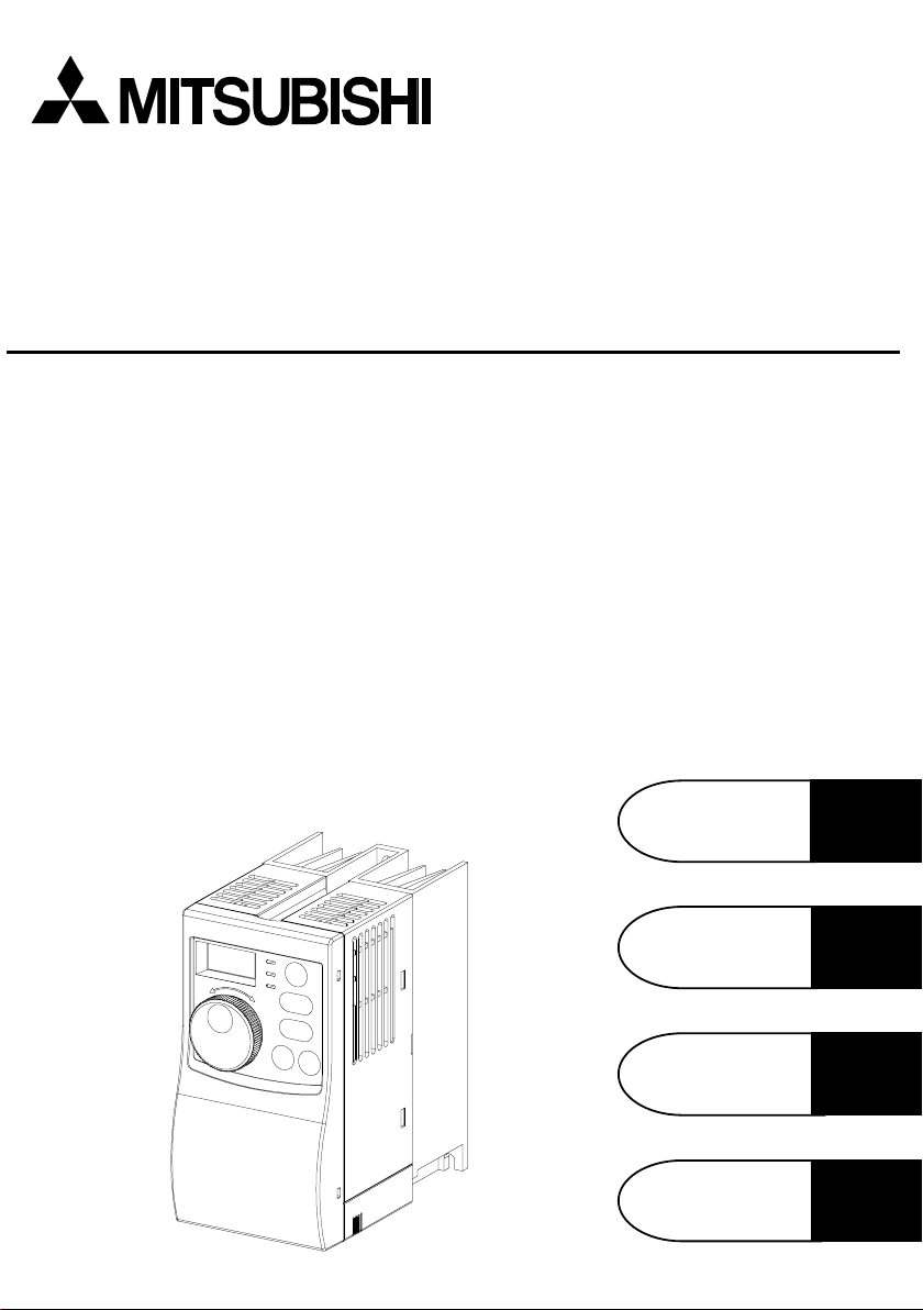
TRANSISTORIZED INVERTER
FR-S
500
IN S T R U C T IO N M A N U A L (D e ta ile d )
W IRING
Chapter 1
FUNCTIONS
PRO TECTIVE
FUNCTIONS
SPECIFICATIONS
Chapter 2
Chapter 3
Chapter 4
Thank you for choosing this Mitsubishi Transistorized inverter.
This instruction manual (detailed) provides instructions for advanced use of the
FR-S500 series inverters.
Incorrect handling might cause an unexpected fault. Before using the inverter, always
read this instruction manual and the instruction manual (basic) [IB-0600026] packed
with the product carefully to use the equipment to its optimum.
This instruction manual uses the International System of Units (SI). The measuring
units in the yard and pound system are indicated in parentheses as reference values.
This section is specifically about safety matters
Do not attempt to install, operate, maintain or inspect the inverter until you have
read through the instruction manual (basic) and appended documents carefully and
can use the equipment correctly. Do not use the inverter until you have a full
knowledge of the equipment, safety information and instructions.
In this instruction manual, the safety instruction levels are classified into
"WARNING" and "CAUTION".
WARNING
CAUTION
Note that even the CAUTION level may lead to a serious consequence according to
conditions. Please follow the instructions of both levels because they are important
to personnel safety.
1. Electric Shock Prevention
While power is on or when the inverter is running, do not open the front cover.
You may get an electric shock.
Do not run the inverter with the front cover removed. Otherwise, you may access
the exposed high-voltage terminals or the charging part of the circuitry and get
an electric shock.
If power is off, do not remove the front cover except for wiring or periodic
inspection. You may access the charged inverter circuits and get an electric
shock.
Before starting wiring or inspection, check for residual voltages with a meter etc.
more than 10 minutes after power-off.
Earth the inverter.
Any person who is involved in wiring or inspection of this equipment should be
fully competent to do the work.
Always install the inverter before wiring. Otherwise, you may get an electric
shock or be injured.
Perform setting dial and key operations with dry hands to prevent an electric shock.
Do not subject the cables to scratches, excessive stress, heavy loads or
pinching. Otherwise, you may get an electric shock.
Do not change the cooling fan while power is on.
It is dangerous to change the cooling fan while power is on.
When you have removed the front cover, do not touch the connector above the
3-digit monitor LED display. You will get an electric shock.
Assumes that incorrect handling may cause hazardous
conditions, resulting in death or severe injury.
Assumes that incorrect handling may cause hazardous
conditions, resulting in medium or slight injury, or may
cause physical damage only.
WARNING
A-1
2. Fire Prevention
CAUTION
Mount the inverter to incombustible material. Mounting it to or near combustible
material can cause a fire.
If the inverter has become faulty, switch off the inverter power. A continuous flow
of large current could cause a fire.
Do not connect a resistor directly to the DC terminals P(+), N(−). This could
cause a fire.
3. Injury Prevention
Apply only the voltage specified in the instruction manual to each terminal to
prevent damage etc.
Ensure that the cables are connected to the correct terminals. Otherwise,
damage etc. may occur.
Always make sure that polarity is correct to prevent damage etc.
While power is on and for some time after power-off, do not touch the inverter or
brake resistor as they are hot and you may get burnt.
4. Additional instructions
Also note the following points to prevent an accidental failure, injury, electric shock, etc.
(1) Transportation and installation
When carrying products, use correct lifting gear to prevent injury.
Do not stack the inverter boxes higher than the number recommended.
Ensure that installation position and material can withstand the weight of the
inverter. Install according to the information in the Instruction Manual.
Do not operate if the inverter is damaged or has parts missing.
When carrying the inverter, do not hold it by the front cover or setting dia l; it may fall off
or fail.
Do not stand or rest heavy objects on the inverter.
Check the inverter mounting orientation is correct.
Prevent screws, wire fragments, other conductive bodies, oil or other flammable
substances from entering the inverter.
Do not drop the inverter, or subject it to impact.
Use the inverter under the following environmental conditions:
Ambient
temperature
Ambient humidity 90%RH or less (non-condensing)
Storage
temperature
Ambience
Environment
Altitude, vibration
*Temperatures applicable for a short time, e.g. in transit.
-10°C to +50°C (14°F to 122°F) (non-freezing)
-20°C to +65°C * (-4°F to 149°F)
Indoors (free from corrosive gas, flammable gas,
oil mist, dust and dirt)
Maximum 1000m (3280.80feet) above sea level for
standard operation. After that derate by 3% for
every extra 500m (1640.40feet) up to 2500m
(8202.00feet) (91%).
5.9m/s
CAUTION
CAUTION
2
or less (conforming to JIS C 0040)
A-2
(2) Wiring
CAUTION
Do not fit capacitive equipment such as power factor correction capacitor, radio
noise filter or surge suppressor to the output of the inverter.
The connection orientation of the output cables U, V, W to the motor will affect
the direction of rotation of the motor.
(3) Trial run
Check all parameters, and ensure that the machine will not be damaged by a
sudden start-up.
When the load GD2 is small (at the motor GD2 or smaller) for 400V from 1.5K to
3.7K, the output current may vary when the output frequency is in the 20Hz to
30Hz range.
If this is a problem, set the Pr. 72 "PWM frecuency selection" to 6kHz or higher.
When setting the PWM to a higher frequency, check for noise or leakage current
problem and take countermeasures against it.
(4) Operation
CAUTION
WARNING
When you have chosen the retry function, stay away from the equipment as it will
restart suddenly after an alarm stop.
The [STOP] key is valid only when the appropriate function setting has been
made. Prepare an emergency stop switch separately.
Make sure that the start signal is off before resetting the inverter alarm. A failure
to do so may restart the motor suddenly.
The load used should be a three-phase induction motor only. Connection of any
other electrical equipment to the inverter output may damage the equipment.
Do not modify the equipment.
CAUTION
The electronic overcurrent protection does not guarantee protection of the motor
from overheating.
Do not use a magnetic contactor on the inverter input for frequent
starting/stopping of the inverter.
Use a noise filter to reduce the effect of electromagnetic interference. Otherwise
nearby electronic equipment may be affected.
Take measures to suppress harmonics. Otherwise power harmonics from the
inverter may heat/damage the power capacitor and generator.
When a 400V class motor is inverter-driven, it should be insulation-enhanced or
surge voltages suppressed. Surge voltages attributable to the wiring constants
may occur at the motor terminals, deteriorating the insulation of the motor.
When parameter clear or all clear is performed, each parameter returns to the
factory setting. Re-set the required parameters before starting operation.
The inverter can be easily set for high-speed operation. Before changing its
setting, fully examine the performances of the motor and machine.
In addition to the inverter's holding function, install a holding device to ensure
safety.
Before running an inverter which had been stored for a long period, always
perform inspection and test operation.
A-3

(6) Maintenance, inspection and parts replacement
CAUTION
Do not carry out a megger (insulation resistance) test on the control circuit of the
inverter.
(7) Disposing of the inverter
CAUTION
Treat as industrial waste.
(8) General instructions
Many of the diagrams and drawings in this instruction manual show the inverter
without a cover, or partially open. Never operate the inverter like this. Always
replace the cover and follow this instruction manual when operating the inverter.
A-4

CONTENTS
1. WIRING 1
1.1 Japanese Version.....................................................................................2
1.1.1 Terminal connection diagram .................................................................... 2
1.1.2 Layout and wiring of main circuit terminals............................................... 3
1.2 North America Version .............................................................................4
1.2.1 Terminal connection diagram .................................................................... 4
1.2.2 Layout and wiring of main circuit terminals............................................... 5
1.3 European Version.....................................................................................7
1.3.1 Terminal connection diagram .................................................................... 7
1.3.2 Layout and wiring of main circuit terminals............................................... 8
1.4 Description of I/O Terminal Specifications ...............................................9
1.4.1 Main circuit.................................................................................................. 9
1.4.2 Control circuit .............................................................................................. 9
1.5 How to Use the Main Circuit Terminals..................................................11
1.5.1 Cables, wiring lengths, crimping terminals, etc...................................... 11
1.5.2 Wiring instructions .................................................................................... 12
1.5.3 Peripheral devices .................................................................................... 13
1.5.4 Leakage current and installation of earth leakage circuit breaker......15
1.5.5 Power-off and magnetic contactor (MC) ................................................. 17
1.5.6 Regarding the installation of the power factor improving reactor ....... 18
1.5.7 Regarding noise and the installation of a noise filter..............................18
1.5.8 Grounding precautions.............................................................................19
1.5.9 Regarding power harmoni cs..................................................................... 20
1.5.10 Japanese power harmonic suppression guideline............................... 20
1.6 How to Use the Control Circuit Terminals..............................................24
1.6.1 Terminal block layout................................................................................24
1.6.2 Wiring instructions .................................................................................... 24
1.6.3 Changing the cont rol logi c........................................................................25
1.7 Input Terminals.......................................................................................28
1.7.1 Run (start) and stop (STF, STR, STOP)................................................. 28
1.7.2 Connectio n o f fr eq uen cy setting potentio mete r a nd output fr eq uen cy
meter (10, 2, 5, 4, AU)..............................................................................31
1.7.3 External frequency selection (REX, RH, RM, RL).................................. 32
1.7.4 Indicator connection and adjustment...................................................... 34
1.7.5 Control circuit common terminals (SD, 5, SE)........................................ 37
1.7.6 Signal inputs by contactless switches..................................................... 37
1.8 How to Use the Input Signals
(Assigned Terminals RL, RM, RH, STR)................................................38
Multi-speed setting (RL, R M, R H, RE X signals): Se tting "0, 1 , 2, 8"
1.8.1
Remote setting (RL, RM, RH signals): Setting "0, 1, 2"......................... 38
1.8.2 Second function selection (RT signal): Setting "3".................................38
I
Contents
1.8.3 Current input selection "AU signal": Setting "4"......................................38
1.8.4 Start self-holding selection (STOP signal): Setting "5"........................... 38
1.8.5 Output shut-off (MRS signal): Setting "6"................................................ 39
1.8.6 External thermal relay input: Setting "7"..................................................39
1.8.7 Jog operation (JOG signal): Setting "9" .................................................. 40
1.8.8 Reset signal: Setting "10"......................................................................... 40
1.8.9 PID control valid terminal: Setting "14".................................................... 41
1.8.10 PU operation/external operation switching: Setting "16" ..................... 41
1.9 Handling of the RS-485 Connector
(Type with RS-485 Communication Function) .......................................41
1.10 Design Information ............................................................................... 44
2.
FUNCTIONS
2.1 Function (Parameter) List.......................................................................46
2.2 List of Parameters Classified by Purpose of Use...................................56
2.3 Explanation of Functions (Parameters)..................................................58
2.3.1 Torque boost
2.3. 2 Ma ximum an d minimu m f re q u en cy
2.3.3 Base frequency, Base frequency voltage
2.3.4 Multi-speed operation
2.3.5 Acceleration/ decel erati on time
2.3.6 Electronic overcurrent protection
2.3.7 DC injection brake
2.3.8 Starting frequency
2.3.9 Load pattern sel ection
2.3.10 Jog frequen cy
2.3.11
2.3.12 Stall prevention function and current limit function
2.3.13 Stall prevention
2.3.14 Acceleration/deceleration pattern
2.3.15 Extended fun ction displ ay selection
2.3.16 Frequency ju mp
2.3.17 Speed di splay
2.3.18 Biases and gai n s o f th e fr eq uen cy setting voltage (curre nt)
2.3.19 Start-time ground fault detection selection
2.4 Output Terminal Function Parameters...................................................78
2.4.1 Up-to-frequency sensitivity
2.4.2 Output frequen cy dete ction
2.5 Current Detection Function Parameters.................................................80
2.5.1 Output current detection functions
2.5.2 Zero current dete ction
2.6 Display Function Parameters.................................................................82
2.6.1 Monitor display
RUN
key rotation direction sel e ction ............................................. 67
...........................................................................58
....................................... 59
...........................................................................65
.....................................................................66
.......................................................................67
to ...............................................................72
................................................................................73
to .......................................................................... 74
........................................................................82
.........................................................64
............................................................69
..............................................................78
............................................................81
II
to
....................................................64
.................................................71
.............................................72
..................................78
....................................................79
........................................80
....................59
to .......61
...................62
......................68
45
2.6.2 Setting dial function sele ction .........................................................83
2.6.3 Monitoring reference
..............................................................84
2.7 Restart Operation Parameters...............................................................84
2.7.1 Restart setting
.........................................................................84
2.8 Additional Function Parameters.............................................................86
2.8.1 Remote setting function selection
..................................................86
2.9 Terminal Function Selection Parameters...............................................88
2.9.1 Input terminal fun ction sele ction
2.9.2 Output terminal function selection
.........................................90
..........................88
2.10 Operation Selection Function Parameters...........................................91
2.10.1 Retry function
2.10.2 PWM carrier frequency
2.10.3 Applied motor
2.10.4 Voltage i npu t sele ction
.................................................................................93
..................................................................93
2.10.5 Input filte r time con sta nt
2.10.6 Re set se le ct io n /PU st o p se le ct io n
2.10.7 Cooling fan operation selection
2.10.8 Parameter w rite i nhib i t selectio n
2.10.9 Reverse rotati on p rev e nti on sele ctio n
2.10.10 Operation mode sele ction
2.10.11 PID cont rol
to ....................................................................101
.....................................................91
........................................................92
................................................................94
................................................94
....................................................96
..................................................97
..........................................98
...........................................................98
2.11 Auxiliary Function Parameters ...........................................................109
2.11.1 Slip compensation
2.11.2 Automati c to rque b oo st sel e ction
2.11.3 Motor primary resistance
.....................................................109
...............................................109
............................................................111
2.12 Calibration Parameters ...................................................................... 111
2.12.1 Meter (frequency meter) calibration
2.12.2 Meter (frequency meter) calibration
(Japanese version)
(NA and EC version) ...... 113
.........111
2.13 Clear Parameters...............................................................................115
2.13.1 P a rameter clear
2.13.2 Alarm history clear
...........................................................................115
.......................................................................115
2.14 Communication Parameters
(Only for the type having the RS - 48 5 co mmun ication function)...........116
2.14.1 Communi ca tion se tti n g s
2.14.2 Operation and speed command write
2.14.3 Link start mode selectio n
2.14.4 E
2
PROM write selection ..............................................................132
to , ......................................118
...............................130
............................................................131
2.15 Parameter Unit (FR-PU04) Setting ....................................................133
2.15.1 Paramete r uni t d i splay language switching
2.15.2 Buzzer sound cont rol
2.15.3 PU contrast adjust ment
..................................................................133
...............................................................134
2.15.4 PU main display screen data selection
2.15.5 PU disconnection de te ction/PU setti ng lock
...............................133
......................................134
..............................135
Contents
III

3. PROTECTIVE FUNCTIONS 136
3.1 Errors (Alarms).....................................................................................137
3.1.1 Error (alarm) definitions..........................................................................137
3.1.2 To know the operati ng sta tus at the occurren ce of alarm
(Only when FR-PU04 is used)...............................................................145
3.1.3 Correspondence between digital and actual characters......................145
3.1.4 Resetting the inverter .............................................................................145
3.2 Troubleshooting....................................................................................146
3.2.1 Motor remains stopped ..........................................................................146
3.2.2 Motor rotates in opposite direction ........................................................147
3.2.3 Speed greatly differs from the setting....................................................147
3.2.4 Acceleration/deceleration is not smooth...............................................147
3.2.5 Motor current is large..............................................................................147
3.2.6 Speed does not increase.......................................................................147
3.2.7 Speed varies during operation...............................................................147
3.2.8 Operation mode is not changed properly..............................................148
3.2.9 Operation panel di spla y is not operating...............................................148
3.2.10 Parameter write cannot be performed................................................148
3.2.11 Motor produces annoying sound.........................................................148
3.3 Precautions for Maintenance and Inspection.......................................149
3.3.1 Precautions for maintenance and inspection........................................ 149
3.3.2 Check items ............................................................................................ 149
3.3.3 Periodic inspection..................................................................................149
3.3.4 Insulation resistance test using megger................................................150
3.3.5 Pressure test........................................................................................... 150
3.3.6 Daily and periodic inspection................................................................. 150
3.3.7 Replacement of parts ............................................................................. 154
3.3.8 Measurement of main circuit voltages, currents and powers..............157
4. SPECIFICATIONS 160
4.1 Specification List ..................................................................................161
4.1.1 Ratings ....................................................................................................161
4.1.2 Common specifications..........................................................................165
4.2 Outline Drawings..................................................................................167
5.
INSTRUCTIONS
5.1 Selecting Instructions ...........................................................................171
5.2 Peripheral Selecting Instruc tio ns..........................................................171
5.3 Operating Instructions ..........................................................................173
5.4 Inverter-driven 400V class motor.........................................................175
170
APPENDIX 176
APPENDIX 1 PARAMETER DATA CODE LIST........................................177
IV

1. WIRING
This chapter explains the basic "wiring" for use of this
product. Always read the instructions before use.
For description of "installation", refer to the instruction
manual (basic).
1.1 Japanese Version......................................................2
1.2 North America Version...............................................4
1.3 European Version......................................................7
1.4 Descriptio n o f I/O Terminal specification....................9
1.5 How to Use the Main Circuit Terminals....................11
1.6 How to Use the Control Circuit Terminals ................24
1.7 Input Terminals........................................................28
1.8 How to Use the Input Signals
(Assigned Terminals RL, RM, RH, STR)..................38
1.9 Handling of the RS-485 Connector
(Type with RS-485 Communication Function).......... 41
1.10 Design Information.................................................44
<Abbreviations>
PU
Control panel and parameter unit (FR-PU04)
Inverter
Mitsubishi transistorized inverter FR-S
FR-S500
Mitsubishi transistorized inverter FR-S
Pr.
Parameter number
1
500
500
series
series
Chapter 1
1
Chapter 2
Chapter 3
Chapter 4
1
.1 Japanese Version
.1.1 Terminal connection diagram
1
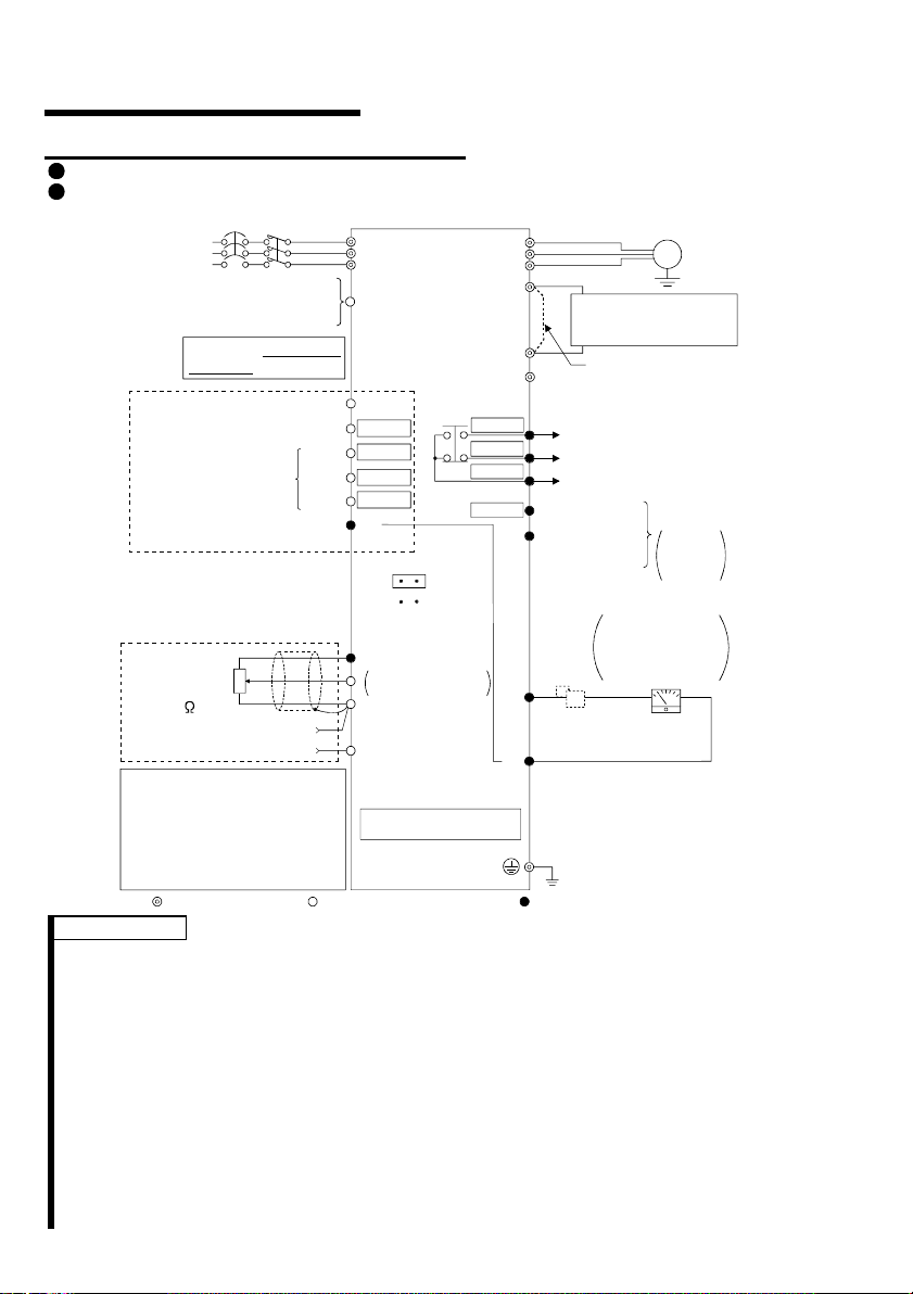
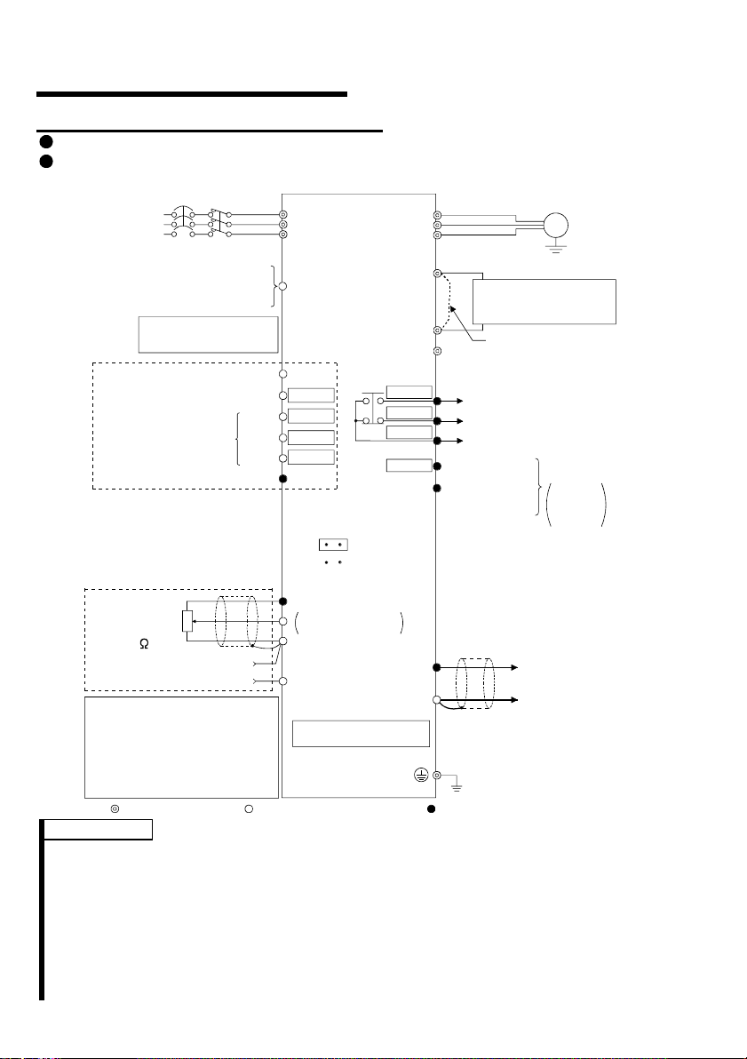
FR-S520-0.1K to 3.7K (-R) (-C)
FR-S540-0.4K to 3.7K (-R)
MC
3-phase AC
power supply
External transistor common
Contact input common (source)
Multi-speed selection
Control input signals
(No voltage input allowe d)
Frequency setting signals (Analog)
Frequency
setting
potentiometer
1/2W1k
(*4)
When using the current input as
the frequency setting signal, set
"4" in any of Pr. 60 to Pr. 63 (input
terminal fu nction selection), assign
AU (current input selection) to any
of terminals RH, RM, RL and STR,
and turn on the AU signal.
NFB
24VDC power supply
Be careful not to short
terminals PC-SD.
Forward rotati on start
Reverse rotation start
High
Middle
Low
Contact input common
3
2
1
Current input (-)
4 to 20mADC (+)
Main circuit terminal Control circuit input t erminal Control circuit out put t erminal
Inverter
R
S
T
PC
STF
STR
*5
RH
*5
RM
*5
*5
RL
SD
(Note)
SINK
SOURCE
10 (+5V)
DC 0 to 5V
2
DC 0 to 10V
5 (Common)
4 (4 to 20mADC)
RS-485 Connector (*1)
*6
*6
*6
*6
(*3)
Selected
RUN
FM
SD
P1
SE
U
V
W
P
N
A
B
C
Power factor improving
DC reactor
(FR-BEL: Option)
Jumper:
jumper when FR-BEL
is connected.
Alarm
output
Running
Open collector
output common
Indicator
1mA full-scale
Analog meter
(Digital indicator)
1mA
Calibration
resistor (*2)
Earth (Ground)
(+) (-)
Motor
IM
Ground
Remove this
Operation status
output
Open
collector
outputs
REMARKS
*1 Only the type with RS-485 communication function.
*2 Not needed when the setting dial is used for calibration. This resistor is used
when calibration must be made near the frequency meter for such a reason as a
remote frequency meter. Note that the needle of the frequency meter may not
deflect to full-scale when the calibration resistor is connected. In this case, use
both the resistor and setting dial for calibration.
*3 You can switch between the sink and source logic positions. Refer to page 25.
*4 When the setting potentiometer is used frequently, use a 2W1kΩ potentiometer.
*5 The terminal functions change with input terminal function selection (Pr. 60 to
Pr. 63). (Refer to page 38, 88) (RES, RL, RM, RH, RT, AU, STOP, MRS, OH,
REX, JOG, X14, X16, (STR) signal selection)
*6 The terminal functions change with output terminal function selection (Pr. 64,
Pr. 65). (Refer to page 90) (RUN, SU, OL, FU, RY, Y12, Y13, FDN, FUP, RL,
LF, ABC signal selection)
2
CAUTION
(
)
)
)
To prevent a malfunct ion due to noise, keep the si gnal cables more than 10cm (3.94i nches)
away from the power cabl es.
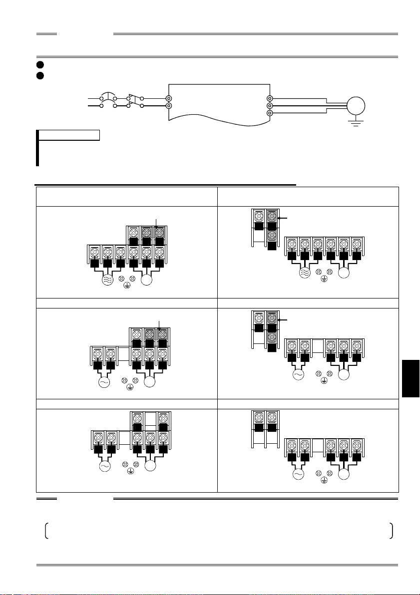
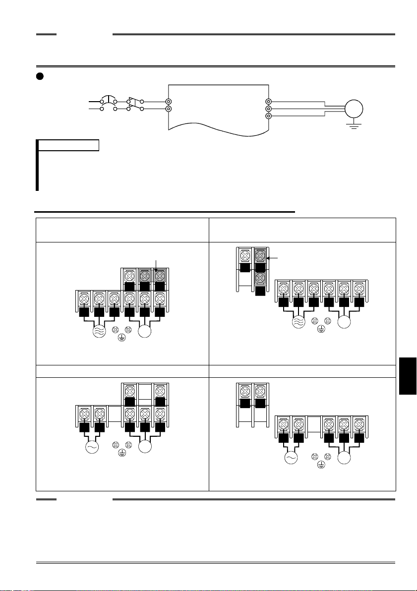
FR-S520S-0.1K to 1.5K (-R) (-C)
FR-S510W-0.1K to 0.75K (-R)
NFB
Power supply
MC
R
S
U
V
W
Motor
IM
REMARKS
To ensure safety, connect the power input to the inv erter via a magn etic contactor and earth
•
leakage circuit breaker or no-fuse breaker, and use the magnetic contactor to switch power on-off.
The output is thr ee-phase 200V.
•
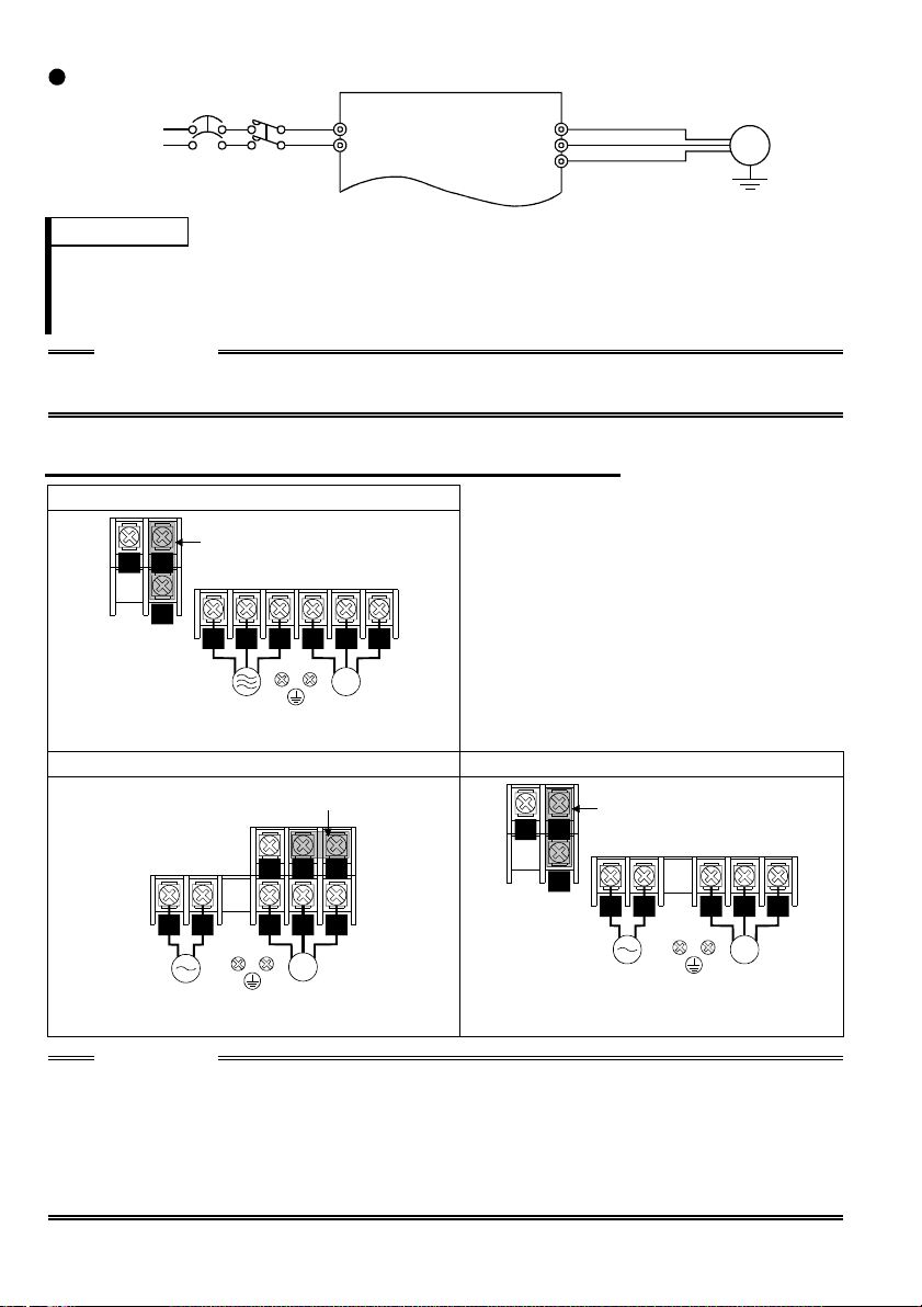
.1.2 Layout and wiring of main circuit terminals
1
FR-S520-0.1K, 0.2K, 0.4K, 0.75K (-R) (-C
Jumper
NP
P1
V
U
RST
Power supply Motor
W
IM
FR-S520-1.5K, 2.2K, 3.7K (-R) (-C)
FR-S540-0.4K, 0.75K, 1.5K, 2.2K, 3.7K (-R
NP
Jumper
P1
R S
T
Power supply Motor
U
W
V
IM
FR-S520S-0.1K, 0.2K, 0.4K, 0.75K (-R) FR-S520S-1.5K (-R)
Jumper
NP
P1
RS
Power supply Motor
V W
U
IM
N
Jumper
P
P1
RS
Power supply Motor
U V
W
IM
FR-S510W-0.1K, 0.2K, 0.4K (-R) FR-S510W-0.75K (-R)
Earth
Ground
1
NP
RS
Power supply Motor
V W
U
IM
NP
RS
Power supply
U
V
IM
Motor
W
CAUTION
The power supply cables must be connected to R, S, T. If they are connected to U, V, W,
•
the inverter will be damaged. (Phase sequence need not be mat ched.)
For use with a singl e-phase power supply, the power suppl y cables must be connected to
R and S.
Connect the motor to U, V, W.
•
Turning on the forward rotation switch (signal) at this time rotates the motor
counterclockwise when viewed from the load shaft.
3
1
.2 North America Version
.2.1 Terminal connection diagram
1
FR-S520-0.1K to 3.7K-NA
FR-S540-0.4K to 3.7K-NA (R)
NFB
3-phase A C
power supply
External transistor common
Contact input common (s our ce )
Frequency setting signals (Anal og )
When using the current input as
the frequency setting signal, set
"4" in any of Pr. 60 to Pr. 63 (input
terminal function selection), assign
AU (current input selection) to any
of terminals RH, RM, RL and STR,
and turn on the AU signal.
24VDC power supply
Take care not to short
terminals PC -SD.
Forward rotation start
Reverse rotation start
Multi-speed selection
Contact input common
Control input signals
(No voltage input allowed)
Frequency
setting
potentiometer
1/2W1k
(*3)
4 to 20mADC (+)
Main circuit terminal Control circuit input terminal
MC
3
2
1
Current input (-)
High
Middle
Low
Inverter
R
S
T
PC
STF
STR
*4
RH
*4
RM
*4
*4
RL
SD
SINK
SOURCE
10 (+5V)
DC 0 to 5V
2
DC 0 to 10V
5 (Common)
4 (4 to 20mADC)
RS-485 Connector (*1)
*5
*5
*5
*5
(*2)
Selected
U
V
W
P1
N
A
B
C
RUN
SE
AM
Power factor improving
DC reactor
(FR-BEL: Option)
P
5
Jumper:
jumper when FR-BEL
is connected.
Alarm
output
Running
Open collector
output common
(+)
(-)
Earth (Ground)
Control circuit output terminal
Motor
IM
Earth
(Ground)
Remove this
Operation status
output
Open
collector
outputs
Analog signal
output
(0 to 5VDC)
REMARKS
*1 Only the type with RS-485 communication function.
*2 You can switch between the sink and source logic positions. Refer to page 25.
*3 When the setting potentiometer is used frequently, use a 2W 1kΩ potentiometer.
*4 The terminal functions change with input terminal function selection (Pr. 60 to
Pr. 63). (Refer to page 38, 88) (RES, RL, RM, RH, RT, AU, STOP, MRS, OH,
REX, JOG, X14, X16, (STR) signal selection)
*5 The terminal functions change with output terminal function selection (Pr. 64,
Pr. 65). (Refer to page 90) (RUN, SU, OL, FU, RY, Y12, Y13, FDN, FUP, RL,
LF, ABC signal selection)
4
NOTE
(
)
y
To prevent a malfunction due to noise, keep the signal cables more than 10cm
(3.94inches) away from the power cables.
FR-S510W-0.1K to 0.75K-NA
NFB
Power supply
MC
R
S
U
V
W
Motor
IM
Earth
Ground
REMARKS
• To ensure safety, connect the power input to the inverter via a magnetic contactor
and earth leakage circuit breaker or no-fuse breaker, and use the magnetic
contactor to switch power on-off.
• The output is three-phase 200V.
.2.2 Layout and wiring of main circuit terminals
1
FR-S520-0.1K, 0.2K, 0.4K, 0.75K-NA
Jumper
NP
P1
RST
Power
supply
U V W
IM
Motor
FR-S520-1.5K, 2.2K, 3.7K-NA
FR-S540-0.4K, 0.75 K, 1.5K, 2. 2K, 3.7K -NA (R)
NP
Jumper
P1
R S T U V W
Power
supply
IM
Motor
FR-S510W-0.1K, 0.2K, 0.4K-NA FR-S510W-0.75K-NA
RS
Power
supply
NP
U V W
IM
Motor
NP
RS
Power
suppl
U V W
IM
Motor
CAUTION
• The power supply cables must be connected to R, S, T. If they are connected to
U, V, W, the inverter will be damaged. (Phase sequence need not be matched.)
• Connect the motor to U, V, W.
Turning on the forward rotation switch (signal) at this time rotates the motor
counterclockwise when viewed from the load shaft.
1
5
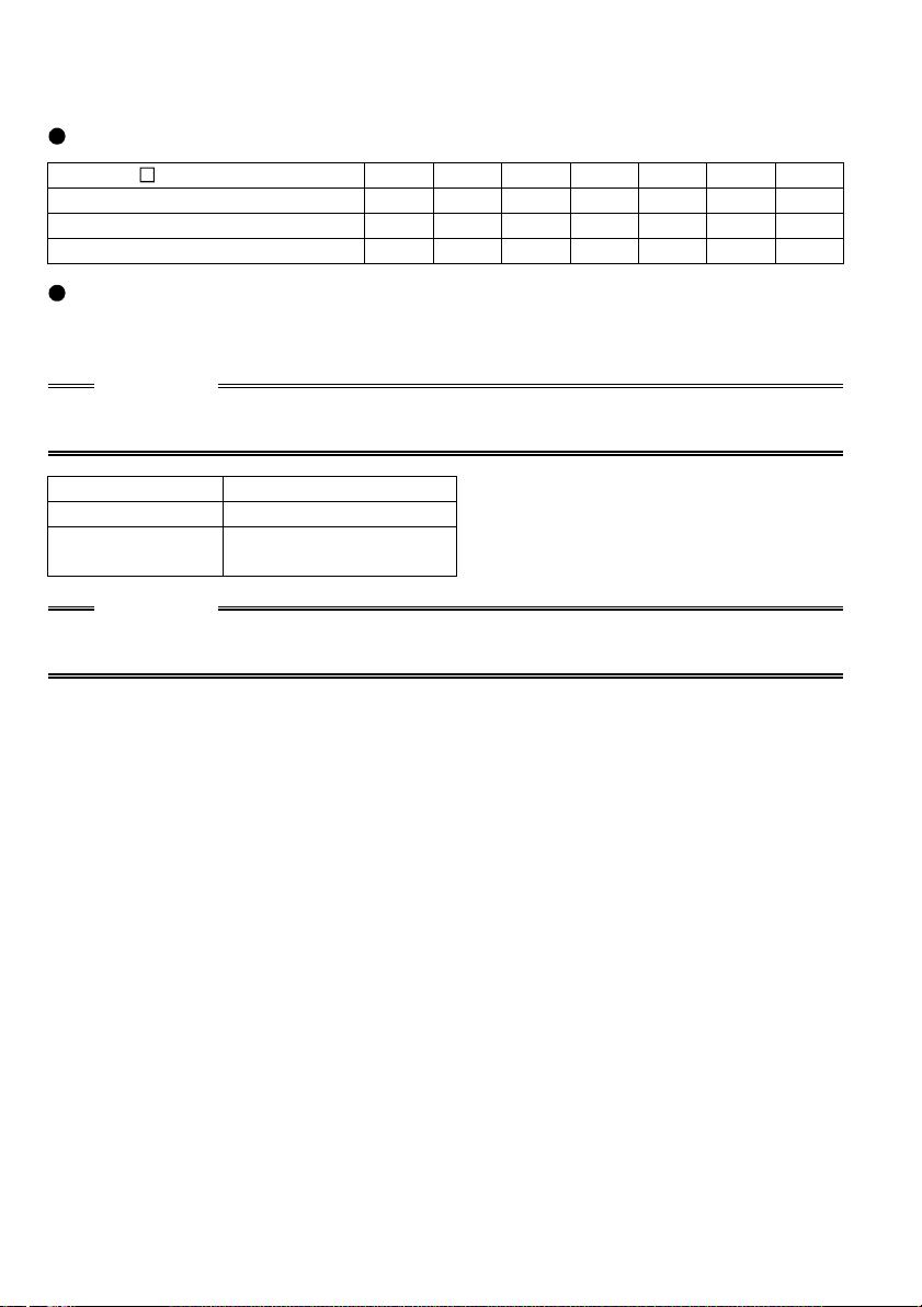
<When single-phase power input is provided for three-phase power input
inverter (NA version only)>
Reduce the output current.
FR-S520- K-NA inverter
Rated output current (A)
Power supply capacity (kVA)
AC input current (A)
0.1 0.2 0.4 0.75 1.5 2.2 3.7
0.4 0.8 1.5 2.5 4.0 5.0 7.0
0.4 0.8 1.5 2.5 4.5 5.5 9.0
1.1 2.4 4.5 6.4 11.2 12.9 17.4
Set m9 (Pr. 637) "current detection filter".
Setting "801" in the manufacturer setting parameter C8 enables you to set the m9
parameter.
CAUTION
Parameters other than m9 can also be made to be displayed, but never alter these
since they are manufacturer setting parameters.
m9 Setting Description
0 Single-phase pow er input
- - -
(Factory setting)
Three-phase power input
CAUTION
Always return the C8 parameter to 0 (factory setting) after you have finished the
setting of m9.
6
1
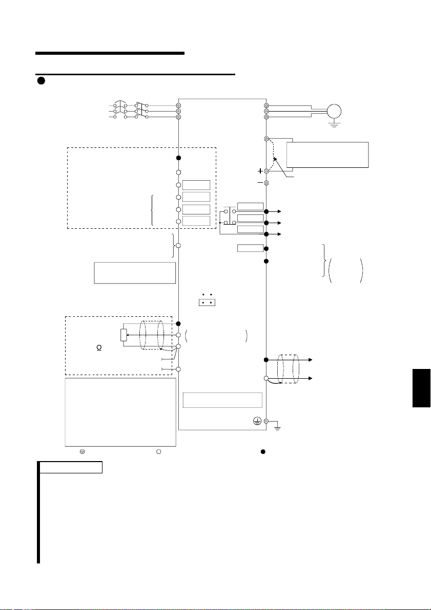
.3 European Version
.3.1 Terminal connection diagram
1
FR-S540-0.4K to 3.7K-EC(R)
MC
3-phase AC
power su pp ly
Control input signals
(No voltage input allowed)
Multi-speed selection
External transistor common
Contact input common (sink)
Frequency setting signals (Analog)
Frequency
setting
potentiometer
1/2W1k
(*3)
When using the current input as
the frequency setting signal, set
"4" in any of Pr. 60 to Pr. 63 (input
terminal function selection) , assi gn
AU (current input selection) to any
of terminals RH, RM, RL and STR,
and turn on the AU signal.
NFB
Contact input common
Forward rotation start
Reverse rotation start
High
Middle
Low
24VDC power supply
Take care not to short
terminals PC-SD.
3
2
1
Current input (-)
4 to 20mADC (+)
Main circuit terminal Control circuit input terminal
Inverter
L
1
L
2
L
3
PC
STF
STR
*4
RH *4
RM
*4
RL *4
SD
SINK
SOURCE
10 (+5V)
DC 0 to 5V
2
DC 0 to 10V
5 (Commo n)
4 (4 to 20mA DC)
RS-485 Connector (*1)
*5
*5
*5
*5
(*2)
Selected
U
V
W
P1
A
B
C
RUN
SE
AM
Power factor improving
DC reactor
(FR-BEL: Option)
Jumper
jumper when FR-BEL
is connected.
Alarm
output
Running
Open collector
output common
(+)
5
Earth (Ground)
Control circuit output terminal
(-)
Motor
IM
Earth
(Ground)
: Remove this
Operation status
output
Open
collector
outputs
Analog signal
output
(0 to 5VDC)
REMARKS
*1 Only the type with RS-485 communication function.
*2 You can switch between the sink and source logic positions. Refer to page 25.
*3 When the setting potentiometer is used frequently, use a 2W 1kΩ potentiometer.
*4 The terminal functions change with input terminal function selection (Pr. 60 to
Pr. 63). (Refer to page 38, 88) (RES, RL, RM, RH, RT, AU, STOP, MRS, OH,
REX, JOG, X14, X16, (STR) signal selection)
*5 The terminal functions change with output terminal function selection (Pr. 64,
Pr. 65). (Refer to page 90) (RUN, SU, OL, FU, RY, Y12, Y13, FDN, FUP, RL,
LF, ABC signal selection)
1
7
FR-S520S-0.2K to 1.5K-EC (R)
NFB
Power supply
MC
1
L
N
U
V
W
Motor
IM
REMARKS
• To ensure safety, connect the power input to the inverter via a magnetic
contactor and earth leakage circuit breaker or no-fuse breaker, and use the
magnetic contactor to switch power on-off.
• The output is three-phase 200V.
NOTE
• To prevent a malfunction due to noise, keep the signal cables more than 10cm
(3.94inches) away from the power cables.
.3.2 Layout and wiring of main circuit terminals
1
FR-S540-0.4K, 0.75K, 1.5K, 2.2K, 3.7K-EC (R)
Earth
(Ground)
-
Jumper
+
P1
L1 L2 L3 U V W
Power
supply
IM
Motor
FR-S520S-0.2K, 0.4K, 0.75K-EC (R) FR-S520S-1.5K-EC (R)
L1 N
Power
supply
Jumper
P1
-
U V W
IM
Motor
-
+
Jumper
+
P1
L1 N
Power
supply
CAUTION
• Connect the motor to U, V, W.
Turning on the forward rotation switch (signal) at this time rotates the motor
counterclockwise when viewed from the load shaft.
1
• For power input wiring, connect L
to R/L1 of the terminal block and N to S/L2 of
the terminal block.
• Do not connect the power supply to U, V and W.
U V W
IM
Motor
8

1
g
g
(
)
g
y
g
g
.4 Description of I/O Terminal Specifications
.4.1 Main circuit
1
Symbol Terminal Name Description
R, S, T *
1
<L
, L2, L3>
U, V, W Inverter output
N<->
P<+>, P1
* R, S <L1, N> terminals for si ngle-phase power input.
AC power input
DC voltage
common
Power factor
improving DC
reactor connection
Earth (Ground)
Connect to the commer cial power supply.
Connect a three-phase squirrel-cage motor .
DC volta
power supply and inverter output.
Disconnect the jumper from terminals P<+>-P1 and
connect the optional power factor imp rov ing DC reactor
(FR-BEL). (The single-phase 100V powe r inpu t model
cannot be connected.)
For grounding the inv erter chassis. Must be earthed.
e common terminal. Not isolated from the
CAUTION
< >Terminal names in parentheses are those of the EC version.
.4.2 Control circuit
1
Symbol Terminal Name Description
STF
STR
RH
Contact input
RM
RL
SD
(*1)
PC
(*1)
Input signals
10
2
4
Frequency setting
Forward rotation
start
Reverse rotation
start
Multi-speed
selection
Contact input
common (sink)
External
transistor
common
24VDC power
supply
Contact input
common
Frequency setting
power supply
Frequency
setting
(Voltage signal)
Frequency
setting
(Current signal)
source
Turn on the STF si
to start forward rotation
and turn it off t o stop.
Turn on the STR signal
to start reverse rotation
and turn it off t o stop.
Turn on the RH, RM and RL signals
in appropriate combinations to select
multiple speeds.
The priorities of the speed commands
are in order of jog, multi-speed setting
(RH, RM, RL, RE X ) and AU .
Common terminal for contact inputs (terminals STF, STR,
RH, RM, RL) and indicator connection (terminal FM).
Isolated from terminals 5 and SE.
When connecting the transistor output (open collector
output), such as a programmable controller (PLC),
connect the positive e xternal power supply for transistor
output to this terminal to prevent a malfunction caused by
undesirable current.
This terminal can be used as a 24V 0.1A DC power
output across t erminals PC-SD.
When source lo
contact input s ignal common.
5VDC. Permissibl e load current 10mA.
entering 0 to 5VDC (0 to 10VDC), the maximum
B
output frequency is reached at 5V (10V) and I/O are
proportional. Use Pr . 73 "0-5V/0- 10V selec tion" t o swit ch
between 5V and 10V.
Input resistance 10kΩ. Maximum permissible voltage 20V.
Enter 4-20mADC. This si
0Hz at 4mA and 60Hz at 20mA. Maximum permissible
input current 30mA. Input resistance approximately 250Ω.
For current input , turn on the signal AU.
Set the AU si
terminal function selection).
nal
When the STF and STR
signals are turned on
simultaneously, the stop
command
is given.
ic is selected, thi s terminal serves as a
nal is factory-adjusted to reac h
nal in any of Pr. 60 to Pr. 63 (input
Input terminal
function selection
(Pr. 60 to Pr. 63)
changes the
terminal functions.
(*4)
1
9

Symbol Terminal Name Description
y
g
g
g
5
Input signals
A
B
C
RUN Inverter running
Open collector
SE
Output signals
Indicator
Frequency
setting input
common
Alarm output
Open collector
output common
For meter
FM
Pulse
<Japanese>
Analog signal
AM
output
Analog
<NA, EC>
Common terminal for the frequenc
(terminals 2, 4) and indicator connection ( terminal AM).
Isolated from terminals SD and SE. Do not earth.
Change-over contact output indicating
that the output has be en stopped by the
inverter's protective function activated.
230V 0.3A AC, 30V 0.3A DC. Alarm:
discontinuity across B-C (continuity
across A-C), normal : continuity across
B-C (discontinuit y across A-C). (*6)
Switched low when the inverter output
frequency is equal t o or higher than the
starting frequency (factory set to 0.5Hz,
variable). Switched high during stop or
DC injection brake operation. (*2)
Permissible load 24VDC 0.1A DC.
Common terminal for inverter runnin
Isolated from terminals 5 and SD.
Factory setting of output item:
One selected from
output frequency
and motor current is
output.
The output signal i s
proportional to the
magnitude of each
monitoring item.
Frequency
Permissible load current 1mA
1440 pulses/s at 60Hz
Factory setting of output item:
Frequency
Output signal 0 to 5VDC
Permissible load current 1mA
setting signals
Output
terminal
function
selection
(Pr. 64, Pr. 65)
changes the
terminal
functions. (*5)
terminal RUN.
Usin
the parameter unit connec tion c able (FR-CB201 to
−−
−−
−−−−
Communication
RS-485 connector
(*3)
205), the parameter unit (FR-PU04) is connectabl e.
Communication operation can be performed throu
RS-485.
*1. Do not connect terminals SD and PC each other or to the earth.
For sink logic, terminal SD acts as the common terminal of contact input. For
source logic, terminal PC acts as the common terminal of contact input. (Refer
to page 25 for the way to switch between them.)
*2. Low indicates that the open collector outputting transistor is on (conducts).
High indicates that the transistor is off (does not conduct).
*3. Compatible with only the type having RS-485 communication function.
(Refer to page 41.)
*4. RL, RM, RH, RT, AU, STOP, MRS, OH, REX, JOG, RES, X14, X16, (STR)
signal selection (Refer to page 88.)
*5. RUN, SU, OL, FU, RY, Y12, Y13, FDN, FUP, RL, LF, ABC signal selection
(Refer to page 90.)
*6. To be compatible with the European Directive (Low Voltage Directive), the
operating capacity of relay outputs (A, B, C) should be 30V 0.3A DC.
10
h
1
g
g
g
g
g
g
g
g
.5 How to Use the Main Circuit Terminals
.5.1 Cables, wiring lengths, crimping terminals, etc.
1
The following selection example assumes the wiring length of 20m (65.62feet).
1) FR-S520-0.1K to 3.7K (-R) (-C)
FR-S520-0.1K to 3.7K-NA
Applicable
Inverter
Model
FR-S520-0.1K
to 0.75K
FR-S520-
1.5K, 2.2K
FR-S520-3.7K
mm
Cables
2
AWG
Terminal
Screw
Size
Ti
htenin
Torque
N
Crimping
Terminals
m
R, S, T U, V, W R, S, T U, V, W R, S, T U, V, W R, S, T U, V, W
M3.5 1.2 2-3.5 2-3.5 2 2 14 14 2.5 2.5
M4 1.5 2-4 2-4 2 2 14 14 2.5 2.5
M4 1.5 5.5-4 5.5-4 3.5 3.5 12 12 4 2.5
Insulated
Cables
2) FR-S540-0.4K to 3.7K (-R)
FR-S540-0.4K to 3.7K-NA (R)
FR-S540-0.4K to 3.7K-EC (R)
Applicable
Inverter
Model
FR-S540-0.4K
to 3.7K
mm
>
Cables
2
U, V, W
R, S, T
1
, L2,
<L
3
L
>
AWG
U, V, W
Terminal
Screw
Size
Ti
htenin
Torque
N
m
Crimping
Terminals
R, S, T
1
<L
, L2,
3
L
>
U, V, W
R, S, T
1
, L2,
<L
3
L
M4 1.5 2-4 2-4 2 2 14 14 2.5 2.5
Insulated
Cables
R, S, T
1
, L2,
<L
3
L
>
3) FR-S520S-0.1K to 1.5K (-R)
FR-S520S-0.2K to 1.5K-EC (R)
Applicable
Inverter
Model
FR-S520S-
0.1K to 0.75K
FR-S520S-
1.5K
mm
Cables
2
U, V, W
AWG
R, S
<L1, N>
U, V, W
Terminal
Screw
Size
Ti
htenin
Torque
N
m
Crimping
Terminals
R, S
1
<L
, N>
U, V, W
R, S
<L1, N>
M3.5 1.2 2-3.5 2-3.5 2 2 14 14 2.5 2.5
M4 1.5 2-4 2-4 2 2 14 14 2.5 2.5
Insulated
Cables
R, S
<L1, N>
4) FR-S510W-0.1K to 0.75K (-R)
FR-S510W-0.1K to 0.75K-NA
Applicable
Inverter
Model
FR-S510W-
0.1K to 0.4K
FR-S510W-
0.75K
mm
Cables
2
AWG
Terminal
Screw
Size
Ti
htenin
Torque
N
Crimping
Terminals
m
R, S U, V, W R, S U, V, W R, S U, V, W
M3.5 1.2 2-3.5 2-3.5 2 2 14 14 2.5 2.5
M4 1.5 5.5-4 2-4 3.5 2 12 14 4 2.5
Insulated
Cables
R, S
1
, N>
<L
PVC
mm
PVC
mm
PVC
mm
PVC
mm
2
2
U, V, W
2
1
U, V, W
2
U, V, W
11

Wiring length
100m (328.08feet) maximum. (50m (164.04feet) maximum for the FR-S540-0.4K.)
CAUTION
• When the wiring length of the 0.1K or 0.2K is 30m (98.43feet) or more, use the
carrier frequency to 1kHz.
• Use the carrier frequency of 1kHz when the wiring length of the FR-S540-0.4K,
0.75K is 30m (98.43feet) or more.
• The wiring length should be 30m (98.43feet) maximum when automatic torque
boost is selected in Pr. 98 "automatic torque boost selection (motor capacity)".
(Refer to page 109)
.5.2 Wiring instructions
1
1) Use insulation-sleeved crimping terminals for the power supply and motor cables.
2) Application of power to the output terminals (U, V, W) of the inverter will damage
the inverter. Never perform such wiring.
3) After wiring, wire off-cuts must not be left in the inverter.
Wire off-cuts can cause an alarm, failure or malfunction. Always keep the inverter
clean.
When drilling a control box etc., take care not to let wire off-cuts enter the inverter.
4) Use cables of the recommended size to make a voltage drop 2% maximum.
If the wiring distance is long between the inverter and motor, a main circuit cable
voltage drop will cause the motor torque to decrease especially at the output of a
low frequency.
5) For long distance wiring, the fast-response current limit function may be reduced or
the devices connected to the secondary side may malfunction or become faulty
under the influence of a charging current due to the stray capacity of wiring.
Therefore, note the maximum overall wiring length.
6) Electromagnetic wave interference
The input/output (main circuit) of the inverter includes harmonic components, which
may interfere with the communication devices (such as AM radios) used near the
inverter. In this case, install the optional FR-BIF radio noise filter (for use in the
input side only) or FR-BSF01 or FR-BLF line noise filter to minimize interference.
7) Do not install a power capacitor, surge suppressor or radio noise filter (FR-BIF
option) in the output side of the inverter.
This will cause the inverter to trip or the capacitor and surge suppressor to be
damaged. If any of the above devices are connected, remove them. (When using
the FR-BIF radio noise filter with a single-phase power supply, connect it to the
input side of the inverter after isolating the T <L
8) Before starting rewiring or other work after performing operation once, check the
voltage with a meter etc. more than 10 minutes after power-off. For some time after
power-off, there is a dangerous voltage in the capacitor.
12
3
> phase securely.)

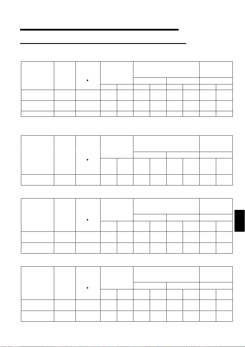
.5.3 Peripheral devices
1
(1) Selection of peripheral devices
Check the capacity of the motor applicable to the inverter you purchased. Appropriate
peripheral devices must be selected according to the capacity.
Refer to the following list and prepare appropriate peripheral devices:
1) FR-S520-0.1K to 3.7K (-R) (-C)
FR-S520-0.1K to 3.7K-NA
Motor
Output
(kW
(HP))
0.1
(1/8)
0.2
(1/4)
0.4
(1/2)
0.75
(1)
1.5
(2)
2.2
(3)
3.7
(5)
Inverter
Model
FR-S520-
0.1K
FR-S520-
0.2K
FR-S520-
0.4K
FR-S520-
0.75K
FR-S520-
1.5K
FR-S520-
2.2K
FR-S520-
3.7K
Rated current of
Circuit Breaker
(Refer to
page 15)
(*1)
30AF/5A S-N10
30AF/5A S-N10
30AF/5A S-N10 FR-BAL-0.4K FR-BEL-0.4K 2 2
30AF/10A S-N10
30AF/15A S-N10 FR-BAL-1.5K FR-BEL-1.5K 2 2
30AF/20A
30AF/30A S-N20 FR-BAL- 3.7KFR-BAL-3. 7K 3.5 3.5
Magnetic
Contactor
(MC)
(Refer to
page 17)
S-N11,
S-N12
Power
Factor
Improving
AC Reactor
(Refer to
page 18)
FR-BAL-0.4K
(*3)
FR-BAL-0.4K
(*3)
FR-BAL-
0.75K
FR-BAL-2.2K FR-BEL-2.2K 2 2
Power
Factor
Improving
DC Reactor
(Refer to
page 18)
FR-BEL-0.4K
(*3)
FR-BEL-0.4K
(*3)
FR-BEL-
0.75K
Cables (mm2)
(*2)
R, S, T U, V, W
22
22
22
2) FR-S540-0.4K to 3.7K (-R)
FR-S540-0.4K to 3.7K-NA (R)
FR-S540-0.4K to 3.7K-EC (R)
Motor
Output
(kW
(HP))
0.4
(1/2)
0.75
(1)
1.5
(2)
2.2
(3)
3.7
(5)
Inverter
Model
FR-S540-
0.4K
FR-S540-
0.75K
FR-S540-
1.5K
FR-S540-
2.2K
FR-S540-
3.7K
Rated current of
Circuit Breaker
(Refer to
page 15)
(*1)
30AF/5A S-N10
30AF/5A S-N10
30AF/10A S-N10
30AF/15A S-N20
30AF/20A S-N20
Magnetic
Contactor
(MC)
(Refer to
page 17)
13
Power
Factor
Improving
AC Reactor
(Refer to
page 18)
FR-BAL-
H0.4K
FR-BAL-
H0.75K
FR-BAL-
H1.5K
FR-BAL-
H2.2K
FR-BAL-
H3.7K
Power
Factor
Improving
DC Reactor
(Refer to
page 18)
FR-BEL-
H0.4K
FR-BEL-
H0.75K
FR-BEL-
H1.5K
FR-BEL-
H2.2K
FR-BAL-
H3.7K
Cables (mm2)
(*2)
R, S, T
1
<L
, L2,
U, V, W
3
>
L
22
22
22
22
22
1

3) FR-S520S-0.1K to 1.5K (-R)
FR-S520S-0.2K to 1.5K-EC (R)
Power
Factor
Improving
DC Reactor
(Refer to
page 18)
(*3)
FR-BEL-
0.75K
Cables (mm2)
R, S
1
<L
22
Motor
Output
(kW
(HP))
0.1
(1/8)
0.2
(1/4)
0.4
(1/2)
0.75
(1)
1.5
(2)
Inverter
Model
FR-S520S-
0.1K
FR-S520S-
0.2K
FR-S520S-
0.4K
FR-S520S-
0.75K
FR-S520S-
1.5K
Power
Rated current of
Circuit Breaker
(Refer to
page 15)
(*1)
30AF/5A S-N10 FR-BAL-0.4K FR-BEL-0.4K 2 2
30AF/10A S-N10 FR-BAL-0.4K FR-BEL-0.4K 2 2
30AF/10A S-N20
30AF/15A S-N20 FR-BAL-1.5K FR-BEL-1.5K 2 2
30AF/20A S-N21 FR-BAL-2.2K FR-BEL-2.2K 2 2
Magnetic
Contactor
(MC)
(Refer to
page 17)
Factor
Improving
AC Reactor
(Refer to
page 18)
(*3)
FR-BAL-
0.75K
4) FR-S510W-0.1K to 0.75K (-R)
FR-S510W-0.1K to 0.75K-NA
Power
Factor
Improving
DC Reactor
(Refer to
page 18)
(*4)
−−
−−
−−−−
−−
−−
−−−−
−−
−−
−−−−
−−
−−
−−−−
Cables (mm2)
R, S
1
<L
22
22
22
3.5 2
Motor
Output
(kW
(HP))
0.1
(1/8)
0.2
(1/4)
0.4
(1/2)
0.75
(1)
Inverter
Model
FR-S510W-
0.1K
FR-S510W-
0.2K
FR-S510W-
0.4K
FR-S510W-
0.75K
Power
Rated current of
Circuit Breaker
(Refer to
page 15)
(*1)
30AF/10A S-N10
30AF/15A S-N10 FR-BAL- 1.5K
30AF/20A S-N20 FR-BAL- 2.2K
30AF/30A S-N20 FR-BAL- 3.7K
Magnetic
Contactor
(MC)
(Refer to
page 17)
Factor
Improving
AC Reactor
(Refer to
page 18)
FR-BAL-
(*3)
0.75K
*1 For installations in the United States or Canada, the circuit breaker must be
inverse time or instantaneous trip type.
*2 The size of the cables assume that the wiring length is 20m (65.62feet).
*3 The power factor may be slightly less.
*4 The single-phase 100V power input model does not allow the power factor
improving DC reactor to be fitted.
, N>
, N>
(*2)
U, V, W
(*2)
U, V, W
14
.5.4 Leakage current and installation of eart h leakag e ci r cui t br eaker
1
Due to static capacitances existing in the inverter I/O wiring and motor, leakage
currents flow through them. Since their values depend on the static capacitances,
carrier frequency, etc., take the following counter measures.
(1) To-ground leakage currents
Leakage currents may flow not only into the inverter's own line but also into the
other line through the ground cable, etc.
These leakage currents may operate earth leakage circuit breakers and earth
leakage relays unnecessarily.
Counter measures
If the carrier frequency setting is high, decrease the carrier frequency (Pr. 72) of
the inverter.
Note that motor noise increases. Selection of Soft-PWM control (Pr. 70) will make
it unoffending. (Factory setting)
By using earth leakage circuit breakers designed for harmonic and surge
suppression (e.g. Mitsubishi's Progressive Super Series) in the inverter's own line
and other line, operation can be performed with the carrier frequency kept high
(with low noise).
(2) Line-to-line leakage currents
Harmonics of leakage
currents flowing in static
capacities between the
inverter output cables
may operate the external
thermal relay
unnecessarily.
Counter measures
Use the electronic overcurrent protection of the inverter.
Decrease the carrier frequency. Note that motor noise increases. Selection of
Soft-PWM (Pr. 70) makes it unoffending.
To ensure that the motor is protected against line-to-line leakage currents, it is
recommended to use a temperature sensor to directly detect motor temperature.
Installation and selection of no-fuse breaker
On the power receiving side, install a no-fuse breaker (NFB) to protect the primary
wiring of the inverter. Which NFB to choose depends on the power supply side
power factor (which changes with the power supply voltage, output frequency and
load) of the inverter. Especially as the completely electromagnetic type NFB
changes in operational characteristic with harmonic currents, you need to choose
the one of a little larger capacity. (Check the data of the corresponding breaker.)
For the earth leakage circuit breaker, use our product designed for harmonic and
surge suppression (Progressive Super Series). (Refer to page 13 for the
recommended models.)
Power
supply
NFB
Inverter
Line-to-Line Leakage Current Path
Thermal relay
Line static
capacitances
Motor
IM
1
CAUTION
Choose the NFB type according to the power supply capacity.
15
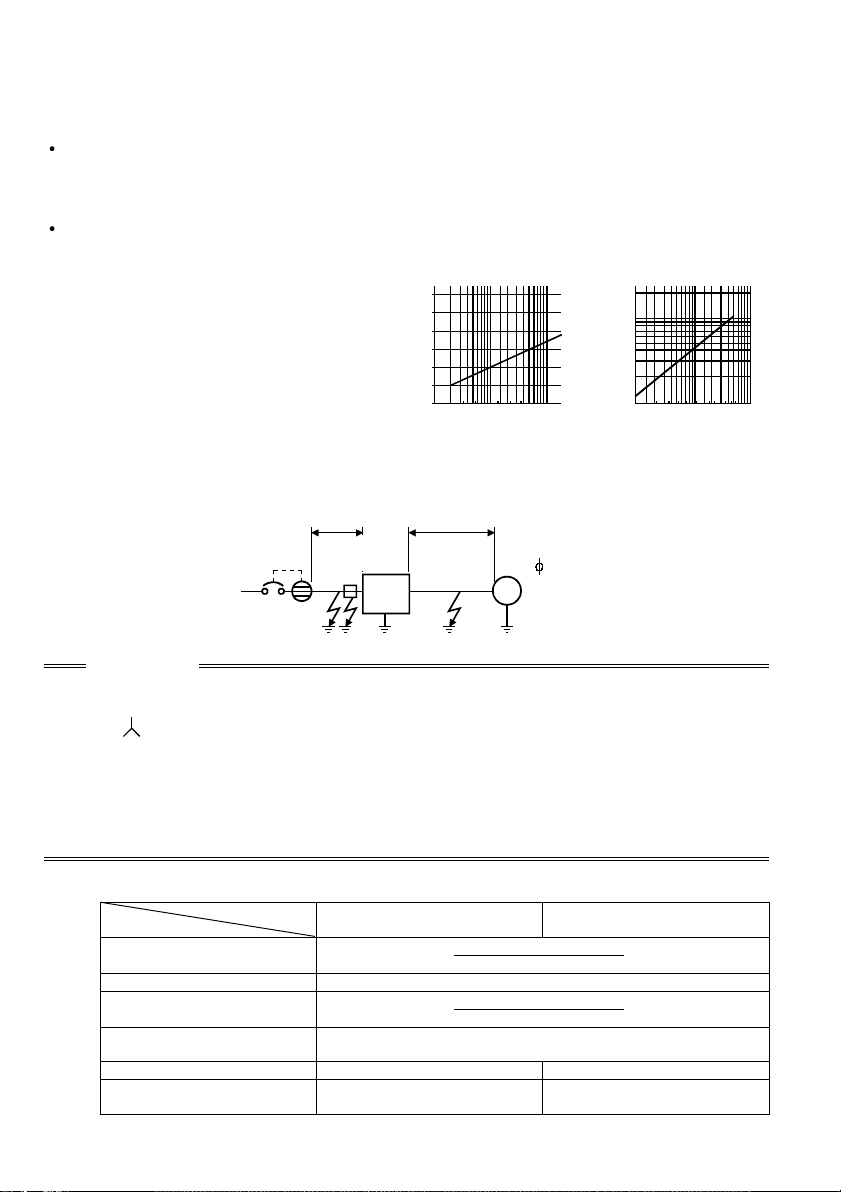
(3) Selecting the rated sensitivity current for the earth leakage circuit
)
(
)
)
(
)
breaker
When using the earth leakage circuit breaker with the inverter circuit, select its rated
sensitivity current as follows, independently of the PWM carrier frequency:
Progressive Super Series
(Type SP, CF, SF, CP)
Rated sensitivity current:
I∆n ≥ 10 × (lg1+Ign+lg2+lgm)
Conventional NV series (Type CA,
CS, SS produced prior to '91)
Rated sensitivity current:
I∆n ≥ 10 × {lg1+lgn+3 × (lg2+lgm)}
lg1, lg2 : Leakage currents of cable
path during commercial
power supply operation
lgn* : Leakage current of noise
filter on inverter input side
lgm : Leakage current of motor
during commercial power
supply operation
<Example>
2mm ×5m
(16.40feet)
NV
Ig1 Ign Ig2 Igm
CAUTION
• The earth leakage circuit breaker should be installed to the primary (power
supply) side of the inverter.
• In the
connection neutral point grounded system, the sensitivity current
becomes worse for ground faults in the inverter secondary side. Hence, the
protective grounding of the load equipment should be 10Ω or less.
• When the breaker is installed in the secondary side of the inverter, it may be
unnecessar ily oper at ed by har m onics if the effe ct ive v alu e i s le ss than the rat ing. In th is
case, do not insta ll the brea ker since th e eddy curre nt and hy steresis loss in crease and
the temperature rises.
* Note the leakage current value of the noise filter installed on the inverter input
side.
Progressive Super Series
Leakage current (Ig1) (mA)
Leakage current (Ign) (mA
Leakage current (Ig2) (mA)
Motor leakage
current (Igm) (mA)
Total leakage current (mA)
Rated sensitivity current
≥≥≥≥
(mA) (
Ig
××××
10)
Example of leakage
current per 1km in cable
path during commercial
power supply operation
when the CV cable is
routed in metal conduit
(200V 60Hz)
120
100
80
60
40
20
0
23.5 814223880
Leakage current (mA)
22
2mm ×70m
5.5 30 60100
Cable size (mm )
(229.66feet)
Noise
filter
Inverter
IM
3
200V
1.5kW
(2HP)
(Type SP, CF, SF,CP)
20
5m (16.40feet)
×
1000m
3280.80feet
0 (without noise filter)
70m (229.66feet)
20
×
1000m
3280.80feet
0.14
1.66 4.78
30 100
Leakage current
example of 3-phase
induction motor
during commercial
power supply
operation
(200V 60Hz)
2.0
1.0
0.7
0.5
0.3
0.2
150
2
0.1
Leakage current (mA)
Motor capacity (kW
Conventional NV
(Type CA, CS, SS)
1.5
2.2
= 0.10
= 1.40
7.515221137
3.7
5.5 18.5
55
45
30
16
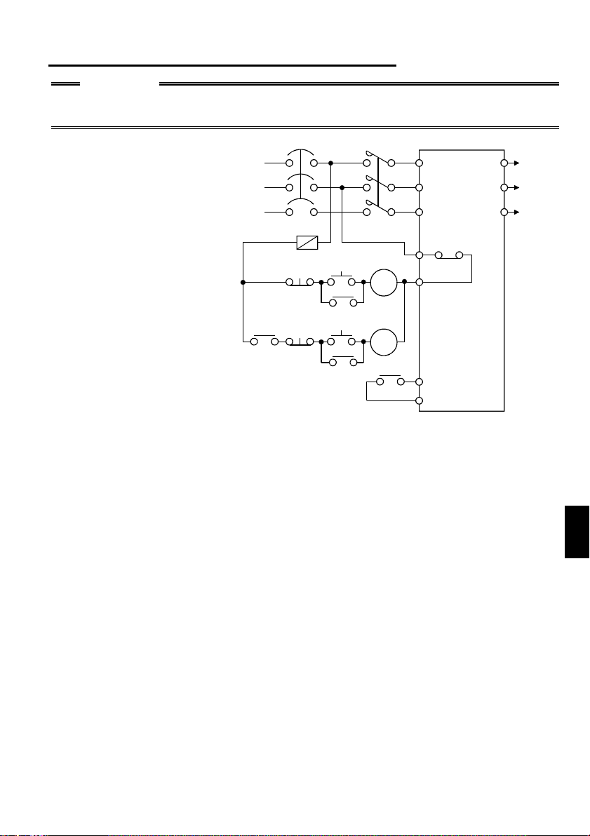
.5.5 Power-off and magnetic contactor (MC)
r
1
CAUTION
Do not use the inverter power supply side magnetic contactor to start or stop the
inverter.
As shown on the right,
always use the start signal
(ON or OFF across
terminals STF or STR-SD)
to make a start or stop.
(Refer to page 28)
NFB
Power
supply
F
OFF
MC
OFF
ON
MC
ON
RA
MC
MC
RA
RA
R<L
>
1
S<N>
T
B
OFF
C
Inverter
STF (STR)
SD
W
U
To
V
moto
Inverter Start/Stop Circuit Example
(1) Inverter's primary side magnetic contactor (MC)
On the inverter's primary side, it is recommended to provide an MC for the following
purposes (Refer to page 13 for selection.):
1) To release the inverter from the power supply when the inverter's protective
function is activated or when the drive is not functioning (e.g. emergency stop
operation).
2) To prevent an accident caused by an automatic restart made at power restoration
after an inverter stop due to a power failure.
3) To rest the inverter for a long time.
The control power supply for inverter is always running and consumes a little
power. When stopping the inverter for a long time, switching inverter power off
saves power slightly.
4) To separate the inverter from the power supply to ensure safety of
maintenance/inspection work.
As the inverter's primary MC is used for the above purposes, it is equivalent to the
standard duty and select the one of class JEM1038-AC3 for the inverter input side
current.
1
17
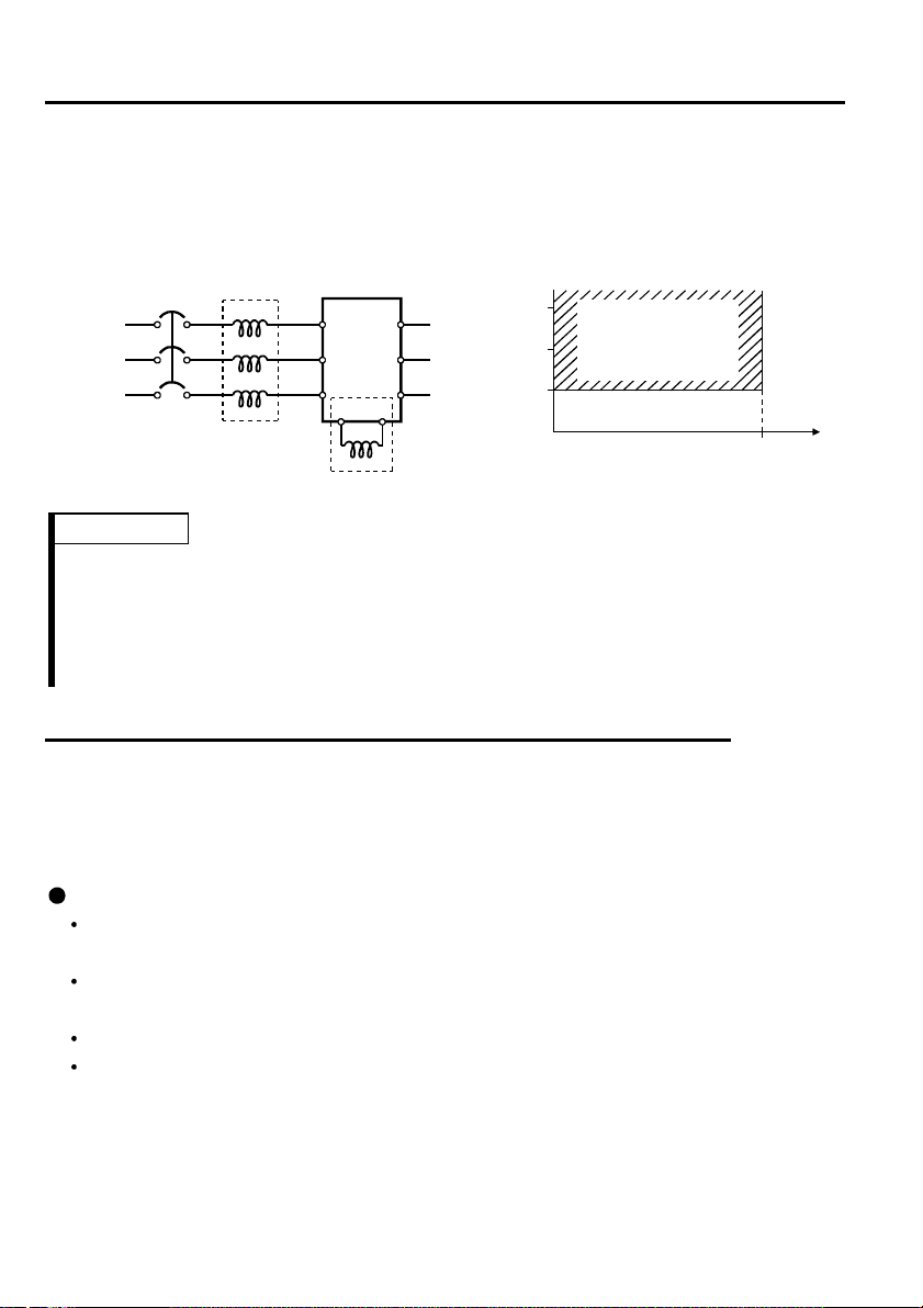
5.6 Regarding the installation of the power factor improvi ng reactor
1.
When the inverter is installed near a large-capacity power transformer (500kVA or
more at the wiring length of 10m (32.81feet) or less) or the power capacitor is to be
switched, an excessive peak current will flow in the power supply input circuit,
damaging the converter circuit. In such a case, always install the power factor
improving reactor (FR-BEL or FR-BAL).
Power
supply
FR-BAL
NFB
R
S
TZ
X
Y
Inverter
R<L
>
1
U
S<N>
V
W
T
P<+>P1
FR-BEL(*)
Power supply equipment
1500
1000
500
capacity (kVA)
Power factor
improving reactor
installation range
010
Wiring length (m)
REMARKS
* When connecting the FR-BEL, remove the jumper across terminals P<+>-P1.
The wiring length between FR-BEL and inverter should be 5m (16.40feet)
maximum and as short as possible.
Use the cables which are equal in size to those of the main circuit. (Refer to page
11)
.5.7 Regarding noise and the installation of a noise filter
1
Some noise enters the inverter causing it to malfunction and others are generated by
the inverter causing the malfunction of peripheral devices. Though the inverter is
designed to be insusceptible to noise, it handles low-level signals, so it requires the
following general counter measures to be taken.
General counter measures
Do not run the power cables (I/O cables) and signal cables of the inverter in
parallel with each other and do not bundle them.
Use twisted shield cables for the detector connecting and control signal cables
and connect the sheathes of the shield cables to terminal SD.
Ground the inverter, motor, etc. at one point.
Capacitances exist between the inverter's I/O wiring, other cables, earth and
motor, through which leakage currents flow to cause the earth leakage circuit
breaker, earth leakage relay and external thermal relay to operate unnecessarily.
To prevent this, take appropriate measures, e.g. set the carrier frequency in Pr. 72
to a low value, use an earth leakage circuit breaker designed for suppression of
harmonics and surges, and use the electronic overcurrent protection built in the
inverter.
18
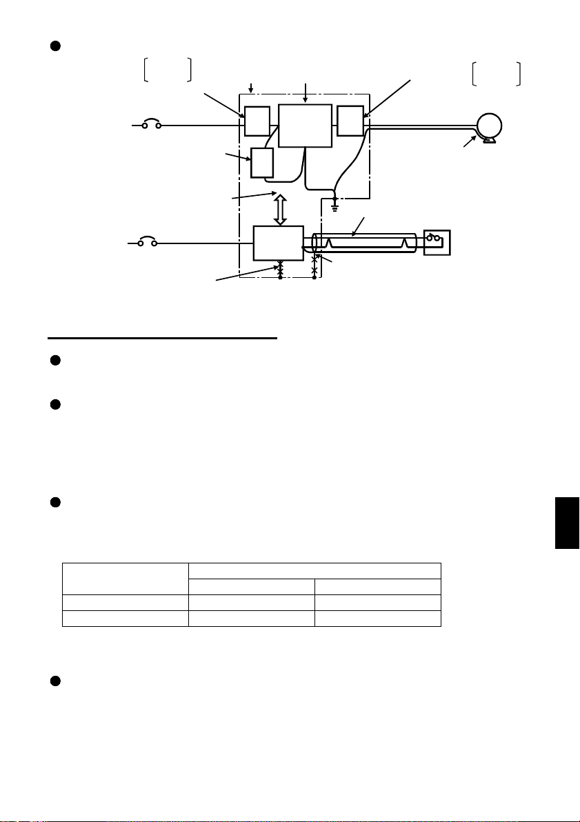
Noise reduction examples
Install filter
on inverter's input side.
Inverter
power su pply
Separate inverte r and power
line more than 30cm (3.94inches)
(at least 10cm (11.81inches))
from sensor circuit.
Control
power su pply
.5.8 Grounding precautions
1
FR-BLF
FR-BSF01
Install filter FR - BIF
on inverter's input side.
Do not earth control
box directly.
Do not earth
control cable.
Control
box
FR-
BLF
FRBIF
Power
supply
for sensor
Reduce carrier
frequency.
Inverter
FRBLF
Use twisted pair shielded cable.
Do not earth shield but connect
it to signal common cable.
Install filter
on inv erter's output si d e.
Use 4-core cable for motor
power cable and use one
cable as earth cable.
Sensor
FR-BLF
FR-BSF01
MotorIM
Leakage currents flow in the inverter. To prevent an electric shock, the inverter and
motor must be grounded.
Use the dedicated ground terminal to ground the inverter. (Do not use the screw in
the casing, chassis, etc.)
Use a tinned* crimping terminal to connect the earth cable. When tightening the
screw, be careful not to break the threads.
*Plating should not include zinc.
Use the thickest possible ground cable. Use the cable whose size is equal to or
greater than that indicated in the following table, and minimize the cable length.
The grounding point should be as near as possible to the inverter.
(Unit: mm2)
Motor Capacity
2.2kW (3HP) or less 2 (2.5) 2 (2.5)
3.7kW (5HP) 3.5 (4) 2 (4)
200V, 100V class 400V class
Ground Cable Size
For use as a product compliant with the Low Voltage Directive, use PVC cable
whose size is indicated within parentheses.
Ground the motor on the inverter side using one cable of the 4-core cable.
19
1
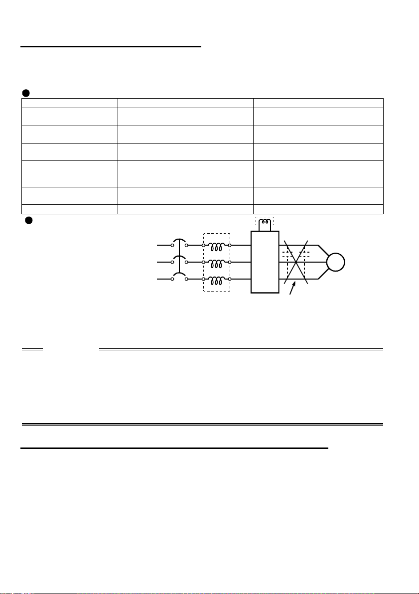
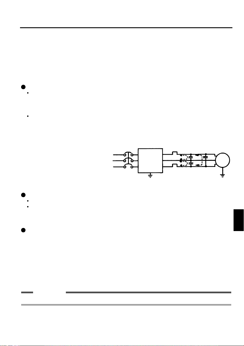
.5.9 Reg ardi ng pow er har mon ics
y
g
(
g
1
The inverter may generate power harmonics from its converter circuit to affect the
power generator, power capacitor etc. Power harmonics are different from noise and
leakage currents in source, frequency band and transmission path. Take the following
counter measure suppression techniques.
The following table indicates differences between harmonics and noise:
Item Harmonics Noise
Frequency
Environment
Quantitative
understanding
Generated amount
Affected equipment
immunity
Suppression example
Suppression technique
Harmonic currents produced
on the power supply side by
the inverter change with such
conditions as whether there
are wiring impedances and a
Normall
less (up to 3kHz or l ess)
To-electric c hannel, power
impedance
Theoretical cal culation possible
Nearly proporti onal to load
capacity
Specified in st andard per
equipment
Provide reactor. Increase distance.
40th to 50th degrees or
NFB
High frequency (several 10kHz
to MHz order)
To-space, distance, wiring path
Random occurrence, quantitative
grasping difficult
e with current variation
Chan
larger as switching speed
ratio
increases)
Different dependin
equipment specifications
Power factor
improving DC reactor
Inverter
on maker's
Motor
IM
power factor improving
reactor and the magnitudes of
output frequency and output
current on the load side.
Power factor
improving AC reactor
Do not provide power factor
improving capacitor.
For the output frequency and output current, we understand that they should be
calculated in the conditions under the rated load at the maximum operating frequency.
CAUTION
The power factor improving capacitor and surge suppressor on the inverter output
side may be overheated or damaged by the harmonic components of the inverter
output. Also, since an excessive current flows in the inverter to activate overcurrent
protection, do not provide a capacitor and surge suppressor on the inverter output
side when the motor is driven by the inverter. To improve the power factor, insert a
power factor improving reactor in the inverter's primary side or DC circuit. For full
information, refer to page 18.
.5.10 Japanese power harmonic suppression guideline
1
Harmonic currents flow from the inverter to a power receiving point via a power
transformer. The harmonic suppression guideline was established to protect other
consumers from these outgoing harmonics.
1) [Harmonic suppression guideline for household appliances and general-purpose
products]
The "harmonic suppression guideline for household appliances and general-purpose
products" issued by ex-Ministry of International Trade and Industry (present Ministry
of Economy, Trade and Industry) in September, 1994 applies to the FR-S500 series
other than the three-phase 400V class. By installing the FR-BEL or FR-BAL power
factor improving reactor, this product complies with the "harmonic suppression
techniques for transistorized inverters (input current 20A or less)" established by the
Japan Electrical Manufacturers' Association.
20
2) "Harmonic suppression guideline for specific consumers"
This guideline sets forth the maximum values of harmonic currents outgoing from a
high-voltage or specially high-voltage consumer who will install, add or renew
harmonic generating equipment. If any of the maximum values is exceeded, this
guideline requires that consumer to take certain suppression measures.
Table 1 Maximum Values of Outgoing Harmonic Currents per 1kW Contract Power
Received Power Voltage 5th 7th 11th 13th 17th 19th 23rd
6.6kV 3.5 2.5 1.6 1.3 1.0 0.9 0.76 0.70
22 kV 1.8 1.3 0.82 0.69 0.53 0.47 0.39 0.36
33 kV 1.2 0.86 0.55 0.46 0.35 0.32 0.26 0.24
Over
23rd
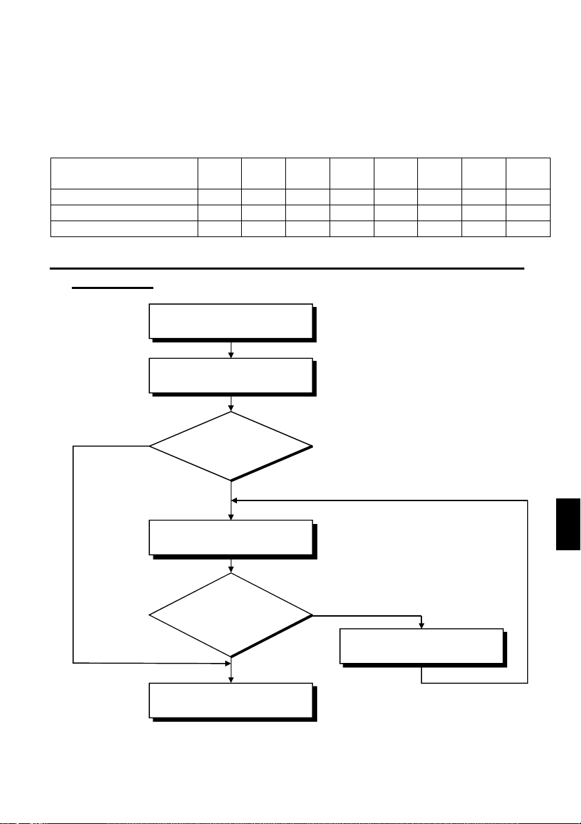
(1) Application of the harmonic suppression guideline for specific
consumers
New installation/addition/
renewal of equipment
Calculation of equivalent
capacity sum
Not more tha n
reference capacity
Sum of equivalent
capacities
Over reference
capacity
Calculation of outgoing
harmonic current
Is outgoing harmonic
current equal to or lower
than maximum value?
Not more than
maximum value
Harmonic suppression
technique is not required.
1
Over maximum value
Harmonic suppression
technique is required.
21

Table 2 Conversion Factors for FR-S500 Series
Class Circuit Type Conversion Factor (Ki)
3-phase bridge
3
(Capacitorsmoothed)
Without reactor K31 = 3.4
With reactor (AC si de) K32 = 1.8
With reactor (DC side) K33 = 1.8
With reactors (AC, DC sides) K34 = 1.4
Table 3 Equivalent Capacity Limits
Received Power Voltage Reference Capacity
6.6kV 50 kVA
22/33 kV 300 kVA
66kV or more 2000 kVA
Table 4 Harmonic Contents (Values at the fundamental current of 100%)
Reactor 5th 7th 11th 13th 17th 19th 23rd 25th
Not used 65 41 8.5 7.7 4.3 3.1 2.6 1.8
Used (AC side) 38 14.5 7.4 3.4 3.2 1.9 1.7 1.3
Used (DC side) 30 13 8.4 5.0 4.7 3.2 3.0 2.2
Used (AC, DC
sides)
28 9.1 7.2 4.1 3.2 2.4 1.6 1.4
1) Calculation of equivalent capacity (P0) of harmonic generating equipment
The "equivalent capacity" is the capacity of a 6-pulse converter converted from the
capacity of consumer's harmonic generating equipment and is calculated with the
following equation. If the sum of equivalent capacities is higher than the limit in
Table 3, harmonics must be calculated with the following procedure:
P0=Σ (Ki× Pi) [kVA]
Ki: Conversion factor (refer to Table 2)
Pi: Rated capacity of harmonic
generating equipment* [kVA]
i: Number indicating the conversion
circuit type
*Rated capacity: Determined by the
capacity of the applied motor and
found in Table 5. It should be noted
that the rated capacity used here is
used to calculate a generated
harmonic amount and is different
from the power supply capacity
required for actual inverter drive.
2) Calculation of outgoing harmonic current
Outgoing harmonic current = fundamental wave current (value converterd from
received power voltage) × operation ratio × harmonic
content
Operation ratio: Operation ratio = actual load factor × operation time ratio during
•
30 minutes
Harmonic content: Found in Table 4.
•
22

Table 5 Rated Capacities and Outgoing Harmonic Currents for Inverter Drive
Rated
Applied
Motor
(kW)
0.75 1.37 83 0.97 53.95 34.03 7.055 6.391 3.569 2.573 2.158 1.494
Current
[A]
400V
0.4 0.81 49 0.57 31.85 20.09 4.165 3.773 2.107 1.519 1.274 0.882
1.5 2.75 167 1.95 108.6 68.47 14.20 12.86 7.181 5.177 4.342 3.006
2.2 3.96 240 2.81 156.0 98.40 20.40 18.48 10.32 7.440 6.240 4.320
3.7 6.50 394 4.61 257.1 161.5 33.49 30.34 16.94 12.21 10.24 7.092
6.6kV
Equivalent of
Fundamental
Wave Current
(mA)
Rated
Capacity
(kVA)
Fundamental Wave Cu rrent Con verted from 6 .6kV
(No reactor, 100% operation ratio)
5th 7th 11th 13th 17th 19th 23rd 25th
3) Harmonic suppression technique requirement
If the outgoing harmonic current is higher than; maximum value per 1kW (contract
power) × contract power, a harmonic suppression technique is required.
4) Harmonic suppression techniques
No. Item Description
Reactor installation
1
(ACL, DCL)
Installation of power
2
factor improving
capacitor
Transformer multi-
3
phase operation
AC filter A capacitor and a reac tor ar e us ed toget her t o r educe i mped anc es
4
Passive filter
(Active filter)
5
Install a reactor (ACL) in the AC side of the inver ter or a reactor
(DCL) in its DC side or both to suppress outgoing harmonic
currents.
When used with a series reactor, the power factor improving
capacitor has an effect of absorbing harmonic currents.
Use two transformers with a phase angle difference of 30° as in
combination to provide an effect corresponding to 12
∆, ∆-∆
pulses, reduci ng low-degree harmonic currents.
at specific frequencies, producing a great effect of absorbing
harmonic current s.
This filter detects the current of a circuit generating a harmonic
current and generates a harmonic current equivalent to a
difference between that cur rent and a f undament al wave c ur rent t o
suppress a harmonic c urr ent at a detec t ion poi nt, pr ovidi ng a great
effect of absorbing harmonic currents.
-
1
23

1
.6 How to Use the Control Circuit Terminals
.6.1 Terminal block layout
1
In the control circuit of the inverter, the terminals are arranged as shown below:
Terminal arrangement
of control circuit
10 2 5 4
RUN
PC SE
FM
BC
A
Terminal screw
size: M3
RL RM RH
SD SD STF
Terminal screw size: M2
STR
<AM>
Japanese version
NA, EC version
REMARKS
For the cable size, wiring length, etc., refer to the instruction manual (basic).
.6.2 Wiring instructions
1
1) Terminals SD, SE and 5 are common to the I/O signals. These common terminals
must not be earthed.
2) Use shielded or twisted cables for connection to the control circuit terminals and run
them away from the main and power circuits (including the 200V relay sequence
circuit).
3) The input signals to the control circuit are micro currents. When contacts are
required, use two or more parallel micro signal contacts or a twin contact to prevent
a contact fault.
*Information on bar terminals
Introduced products (as of June, 2000): Phoenix Contact Co.,Ltd.
Terminal Screw Size
M3 (A, B, C terminals)
M2
(Other than the above)
Bar Terminal Model
(With Insulation
Sleeve)
Al 0.5-6WH A 0.5-6 0.3 to 0.5
Al 0.75-6GY A 0.75-6 0.5 to 0.75
Al 0.5-6WH A 0.5-6 0.3 to 0.5
Bar Terminal Model
(Without Insulation
Sleeve)
Wire Size (mm
2
)
Bar terminal crimping terminal: CRIMPFOX ZA3 (Phoenix Contact Co., Ltd.)
CAUTION
When using the bar terminal (without insulation sleeve), use care so that the
twisted wires do not come out.
24

.6.3 Changing the control logic
1
The input signals are set to sink
logic for the Japanese and NA
version, and to source logic for
the EC version.
To change the control logic, the
connector under the setting dial
must be moved to the other
position.
Change the connector position
using tweezers, a pair of longnose pliers etc.
Change the connector position
before switching power on.
CAUTION
• Make sure that the front cover is installed securely.
• The front cover is fitted with the capacity plate and the inverter unit with the rating
plate. Since these plates have the same serial numbers, always replace the
removed cover onto the original inverter.
• The sink-source logic change-over connector must be fitted in only one of those
positions. If it is fitted in both positions at the same time, the inverter may be
damaged.
NA and Japanese version
EC version
25
1

1) Sink logic type
A
t
In this logic, a signal switches on when a current flows out of the corresponding
signal input terminal.
Terminal SD is common to the contact input signals. Terminal SE is common to the
open collector output signals.
A current flows out of
Current
STF
STR
the corresponding
R
signal RUN
Inverter
RUN
R
AX40
1
R
R
SD
Connecting a positive external power supply
for transistor output to terminal PC prevents
a malfunction caused by a undesirable
current. (Do not connect terminal SD of the
inverter with terminal 0V of the external
power supply. When using terminals PC-SD
as a 24VDC power supply, do not install an
external power supply in parallel with the
inverter. Doing so may cause a malfunction
in the inverter due to a undesirable current.)
SE
9
24VDC
Y40 type
ransistor
output module Inverter
1
STF
2
STR
3
RH
4
RM
5
RL
9
PC
24VDC
10
SD
24VDC
(SD)
26

2) Source logic type
In this logic, a signal switches on when a current flows into the corresponding signal
input terminal.
Terminal PC is common to the contact input signals. For the open collector output
signals, terminal SE is a positive external power supply terminal.
A current flows out of
PC
the corresponding
signal RUN
Inverter
AX80
Current
STF
STR
R
R
Connecting the 0V terminal of the
external power supply for transistor
output to terminal SD prevents a
malfunction caused by a undesirable
current.
AY-80
RUN
SE
24VDC
9
1
2
10
PC
STF
STR
SD
24VDC
1
R
9
Inverter
R
24VDC
(SD)
1
27

1
yp
.7 Input Terminals
.7.1 Run (start ) and stop (STF, STR, STOP)
1
To start and stop the motor, first switch on the input power supply of the inverter
(switch on the magnetic contactor, if any, in the input circuit during preparation for
operation), then start the motor with the forward or reverse rotation start signal.
(1) Two-wire type connection (STF, STR)
Output frequency
NFB
2-wire t
R<L
>,S<N>,T
1
Inverter
STF
STR (Pr.63= "- - -" )
SD
Time
ON
e connection example
A two-wire type connection is shown on
the right.
1) The forward/reverse rotation signal is
used as both the start and stop
signals. Switch on either of the
forward and reverse rotation signals
to start the motor in the corresponding
Power
supply
Forward
rotation start
Reverse
rotation start
direction. Switch on both or switch off
the start signal during operation to
decelerate the inverter to a stop.
2) The frequency setting signal may
either be given by entering 0 to 5VDC
(or 0 to 10VDC) across frequency
setting input terminal 2-5 or by setting
the required values in Pr. 4 to Pr. 6
"multi-speed setting" (high, middle,
low speeds). (For multi-speed
operation, refer to page 32.)
Across
STF-SD
(STR)
3) After the start signal has been input, the inverter starts operating when the
frequency setting signal reaches or exceeds the "starting frequency" set in Pr. 13
(factory-set to 0.5Hz).
If the motor load torque is large or the "torque boost" set in Pr. 0 is small, operation
may not be started due to insufficient torque until the inverter output frequency
reaches about 3 to 6Hz.
If the "minimum frequency" set in Pr. 2 (factory setting = 0Hz) is 6Hz, for example,
merely entering the start signal causes the running frequency to reach the minimum
frequency of 6Hz according to the "acceleration time" set in Pr. 7.
4) To stop the motor, operate the DC injection brake for the period of "DC injection
brake operation time" set in Pr. 11 (factory setting = 0.5s) at not more than the DC
injection brake operation frequency or at not more than 0.5Hz.
To disable the DC injection brake function, set 0 in either of Pr. 11 "DC injection
brake operation time" and Pr. 12 "DC injection brake voltage".
In this case, the motor is coasted to a stop at not more than the frequency set in
Pr. 10 "DC injection brake operation frequency" (0 to 120Hz variable) or at not more
than 0.5Hz (when the DC dynamic brake is not operated).
5) If the reverse rotation signal is input during forward rotation or the forward rotation
signal is input during reverse rotation, the inverter is decelerated and then switched
to the opposite output without going through the stop mode.
28

(2) Three-wire type connection (STF, STR, STOP)
(
A three-wire type connection is shown
on the right. Assign the start self-holding
signal (STOP) to any of the input
Power
supply
terminals. To make a reverse rotation
start, set Pr. 63 to "- - -"
factory setting).
1) Short the signal STOP-SD to enable
the start self-holding function. In this
case, the forward/reverse rotation
signal functions only as a start signal.
(Note) Assign the stop signal to any of
Pr. 60 to Pr. 62 (input terminal
function selection).
2) If the start signal terminal STF (STR)SD are shorted once, then opened, the
start signal is kept on and starts the
inverter. To change the rotation
direction, short the start signal STR
(STF)-SD once, then open it.
(Note) Assign the stop signal to any of
Pr. 60 to Pr. 62 (input terminal
function selection).
3) The inverter is decelerated to a stop by
opening the signal STOP-SD once. For
the frequency setting signal and the
operation of DC dynamic brake at a
stop time, refer to paragraphs 2) to 4) in
(1) Two-wire type connection. The right
diagram shows 3-wire type connection.
4) When the signal JOG-SD is shorted, the STOP signal is invalid and the JOG signal
has precedence.
5) If the output stop signal MRS-SD is shorted, the self-holding function is not
deactivated.
DC Injection Brake and Coasting to Stop functionality
Operation
Mode
DC Injection
Brake
DC injection
brake enabled
DC injection
brake disabled
*1: Also stopped by the
External Operation or Combined
Terminals STF
(STR)-SD
disconnected
DC injection
brake operated at
not more than
"DC injection
brake operation
frequency" set in
Pr. 10
Coasted to a stop
at not more than
"DC injection
brake operation
frequency" set in
Pr. 10
Operation
Pr. 79 = "0", "2", "3"
Set frequency
(*1)
changed to 0Hz
DC injection
brake operated at
0.5Hz or less.
Coasted to a stop
at 0.5Hz or less.
STOP
key. Refer to page 94.
RESET
NFB
Forward
rotation start
Stop
Reverse
rotation start
Output frequency
Start
Stop
3-wire type connection exa mple
ON
PU Operation or Combined
Pr. 79 = "0", "1", "4"
Stop key
DC injection
brake operated at
not more than
"DC injection
brake operation
frequency" set in
Pr. 10
Coasted to a stop
at not more than
"DC injection
brake operation
frequency" set in
Pr. 10
R<L
Inverter
STF
STR (Pr.63= "- - -" )
STOP
SD
Operation
>,S<N>,T
1
Time
ON
Set frequency
changed to 0Hz
DC injection
brake operated at
0.5Hz or less.
Coasted to a stop
at 0.5Hz or less.
1
29

e
Start signal
terminal
Across STF-SD
Across STR-SD
Output frequency
Start
signal
terminal
Across
STF-SD
Across
STR-SD
DC injection brake disabledDC injection brake enabled
DC injection brake
Starting frequency
Pr.13
(*1)
0.5Hz
Output frequency
ON
DC injection brake
operation
frequency Pr. 10
3Hz
0.5Hz
0.5s
DC injection
brake operation
time Pr. 11
(*3)
(*2)
ON
0.5Hz
0.5s
DC injection
brake operation
time Pr. 11
(*3)
not operated
ON
Start/Stop Timing Chart (for two-wire type)
Starting
frequency
Pr.13
(*1)
0.5Hz
Start signal switched on
while DC injection brake
is being operated
Forward
rotation
Reverse
rotation
ON
ON
3Hz
0.5Hz
DC injection brake operation
frequency Pr. 10
Forward
rotation
ON
ON
(*4)
DC injection
3Hz
brake enabled
0.5s
DC injection brake
operation time Pr. 11
(*3)
Forward-Reverse Rotation Switch-Over Timing Chart
(*4)
3Hz
Coasted to
a stop
Tim
Time
REMARKS
*1 The "starting frequency" in Pr. 13 (factory-set to 0.5Hz) may be set between 0
and 60Hz.
*2. If the next start signal is given during DC injection brake operation, the DC
injection brake is disabled and restart is made.
*3. The "DC injection brake operation time" in Pr. 11 (factory-set to 0.5s) may be
set between 0 and 10s.
*4. The frequency at which the motor is coasted to a stop is not more than the "DC
injection brake operation frequency" set in Pr. 10 (factory setting = 3Hz; may be
set between 0 and 120Hz) or not more than 0.5Hz.
*5. The "starting frequency" in Pr. 13, "DC injection brake operation time" in Pr. 11
and "DC injection brake operation frequency" in Pr. 10 are the factory-set
values.
30

.7.2 Connection of frequency setting potentiometer and output
1
frequency meter (10, 2, 5, 4, AU)
The analog frequency setting input signals that may be entered are voltage and
current signals.
For the relationships between the frequency setting input voltages (currents) and
output frequencies, refer to the following diagram. The frequency setting input signals
are proportional to the output frequencies. Note that when the input signal is less than
the starting frequency, the output frequency of the inverter is 0Hz.
If the input signal of 5VDC (or 10V, 20mA) or higher is entered, the output frequency
does not exceed the maximum output frequency.
Frequency setting
voltage gain frequency
Frequency setting
current gain frequency
(Hz)
Output frequencies
Relationships between Frequency Setting Inputs and Output Frequencies
(1 to 120Hz)
Maximum frequency
(0 to 120Hz)
Minimum frequency
(0 to 120Hz)
Starting frequency
(0 to 60Hz)
0.5
Input voltage is
proportional to
output
frequency.
0
Frequency setting signal
Pr.13
5V
(10V)
(20mA)
Pr.73
Pr.2
Pr.1
Pr.38
Pr.39
REMARKS
For the way to calibrate the output frequency meter, refer to the instruction manual
(basic).
(1) Voltage input (10, 2, 5)
Enter the frequency setting input signal of 0 to 5VDC (or 0 to 10VDC) across the
frequency setting input terminals 2-5. The maximum output frequency is reached
when 5V (10V) is input across terminals 2-5.
The power supply used may either be the inverter's built-in power supply or an
external power supply. For the built-in power supply, terminals 10-5 provide 5VDC
output.
For operation at 0 to 5VDC, set "0" in
Pr. 73 to the 0 to 5VDC input. Use
terminal 10 for the built-in power
supply.
+5V 10
0 to 5VDC
2
5
For operation at 0 to 10VDC, set "1" in
Pr. 73 to the 0 to 10VDC input.
0 to 10VDC
2
5
31
1

(2) Current input (4, 5, AU)
R
To automatically perform operation under constant pressure or temperature control
using a fan, pump etc., enter the controller output signal of 4 to 20mADC across
terminals 4-5.
Terminals AU-SD must be shorted to use the 4 to 20mADC signal for operation.
(Assign the signal AU using any of Pr. 60 to Pr. 63.)
When the multi-speed signal is input, the current input is ignored.
Automatic signal
.7.3 External frequency selection (REX, RH, RM, RL)
1
Up to 15 speeds (*) may be selected for an external command forward rotation start or
up to 7 speeds for an external command reverse rotation start according to the
combination of connecting the multi-speed select terminals REX, RH, RM and RL-SD,
and multi-speed operation can be performed as shown below by shorting the start
signal terminal STF (STR)-SD.
Speeds (frequencies) may be specified as desired from the operation panel or
parameter unit as listed below.
Automatic/manual
signal switching
Manual operation
Frequency setting
potentiometer
DC4-20mA
Manual-Autom a tic Switching
AU
SD
10
2
Inverter
5
4
Across
AU-SD
Operation
Automatic
operation
4 to 20m A
OFFON
Manual
operation
0 to 5V
(0 to 10V)
CAUTION
•* Change the setting of Pr. 63 "STR terminal function selection" to "8", and assign
and use the 15-speed select signal (REX).
• Has precedence over the main speed setting signal (0 to 5V, 0 to 10V, 4 to 20mA
DC).
Speed 1
(high speed)
Speed 2
(middle speed)
Speed 3
(low speed)
Output frequency (Hz)
ON ON ON ON
RH
M
RL
REX
ON ON ON ON
Speed 5
Speed 4
Speed 6
Speed 7
ONONON
Time
RH
RM
RL
REX
Speed 10
Speed 11
Speed 9
Speed 8
Output frequency (Hz)
ON ON ON ON
ON ON ON ON
ONON ON ON ON ON ON ON
Speed 12
Speed 13
ON ON ON ON
32
Speed 14
Speed 15
Time

Multi-Speed Setting
Speed
Speed 1
(high
speed)
Speed 2
(middle
speed)
Speed 3
(low
speed)
Speed 4
Speed 5
Speed 6
Speed 7
Speed 8
Speed 9
Speed 10
Speed 11
Speed 12
Speed 13
Speed 14
Speed 15
External
setting
Terminal Input
REX-
RH-SDRM-SDRL-
SD*
OFF ON
OFF OFF ON
OFF OFF OF F ON
OFF OFF ON
OFF ON
OFF ON
OFF ON
OFF OFF OFF
ON
ON
OFF OF F ON
ON
OFF ON OFF
OFF ON ON
ON
ON OFF OFF
ON
ON OFF ON
ON
ON ON OFF
ON
ON
ON ON ON
OFF OFF OFF OFF
SD
OFF OFF
OFF
ON
OFF ON
ON OFF
ON ON
Parameter
Pr. 4 0 to 120Hz
Pr. 5 0 to 120Hz
Pr. 6 0 to 120Hz
Pr. 24 0 to 120Hz, - - - Pr. 6 setting when Pr. 24="- - -"
Pr. 25 0 to 120Hz, - - - Pr. 6 setting when Pr. 25="- - -"
Pr. 26 0 to 120Hz, - - - Pr. 5 setting when Pr. 26="- - -"
Pr. 27 0 to 120Hz, - - - Pr. 6 setting when Pr. 27="- - -"
Pr. 80 0 to 120Hz, - - - 0Hz when Pr. 80="- - -"
Pr. 81 0 to 120Hz, - - - Pr. 6 setting when Pr. 81="- - -"
Pr. 82 0 to 120Hz, - - - Pr. 5 setting when Pr. 82="- - -"
Pr. 83 0 to 120Hz, - - - Pr. 6 setting when Pr. 83="- - -"
Pr. 84 0 to 120Hz, - - - Pr. 4 setting when Pr. 84="- - -"
Pr. 85 0 to 120Hz, - - - Pr. 6 setting when Pr. 85="- - -"
Pr. 86 0 to 120Hz, - - - Pr. 5 setting when Pr. 86="- - -"
Pr. 87 0 to 120Hz, - - - Pr. 6 setting when Pr. 87="- - -"
Frequency
setting
potentiometer
Set Frequency
Range
0 to max. setting
Remarks
———————
———————
———————
———————
*When using the REX signal, a reverse rotation start cannot be made by the
external command.
Motor
IM
*1
Frequency
setting
potentiometer
Power supply
Forward rotation
Multi-speed
selection
R<L
S<N>
T
STF
REX
RH
RM
RL
SD
>
1
Inverter
*2
U
V
W
10
2
5
Multi-Speed Operation Connection Example
REMARKS
*1: When the frequency setting potentiometer is connected, the input signal of the
frequency setting potentiometer is ignored if the multi-speed select signal is
switched on. (This also applies to the 4 to 20mA input signal.)
*2: For a reverse rotation start, set Pr. 63 to "- - -" (factory setting).
33
1

.7.4 Indicator connection and adjustment
1
(1) Japanese version (FM)
The output frequency, etc. of the inverter can be indicated by a DC ammeter of 1mA
full-scale deflection and maximum 300Ω internal resistance or a commercially
available digital indicator which is connected across terminals FM-SD.
The indicator can be calibrated from the operation panel or parameter unit. Note that
the reading varies according to the wiring distance if the indicator is placed away from
the inverter. In this case, connect a calibration resistor in series with the indicator as
shown below and adjust until the reading matches the operation panel or parameter
unit indication (indicator monitoring mode).
Install the indicator within 200m (656.16feet) (50m (164.04feet) for the digital
indicator) of the inverter and connect them by at least 0.3mm
cables.
2
twisted or shielded
Inverter
Calibration resis tor*
FM
1mA
SD
(+)
Analog
indicator
(-)
(1mA full-scale)
Inverter
1440 pulses/s
FM
SD
Digital indicator
Types of Indicators Connected
REMARKS
* Not needed when calibration is made using the calibration parameter C1 "FM
terminal calibration". This resistor is used when calibration must be made near the
frequency meter for such a reason as a remote frequency meter. Note that the
needle of the frequency meter may not deflect to full-scale when the calibration
resistor is connected. In this case, use both the resistor and calibration parameter
"C1".
CAUTION
• Refer to page 111 for the procedure of indicator adjustment.
34

Output waveform of terminal FM
The output signal of terminal FM has a pulse waveform as shown in the table below
and the number of its pulses is proportional to the inverter output frequency.
The output voltage (average voltage) is also proportional to the output frequency.
Terminal FM Output Voltage
Output
waveform
Specifications
Calibration parameter C1 (Pr. 900)
8V
Inverter
24V
Max. 2400 pulses/s
Number
of output
pulses
(pulses/
second)
Output
voltage
*1. 0.5V or less when a DC ammeter of 300Ω or less internal resistance is connected
to measure the output voltage.
Adjustment
Analog meter
To adjust the reading of an analog indicator (ammeter), turn the calibration resistor
to change the current.
When using the operation panel or parameter unit for adjustment, change the pulse
width of the output waveform (calibration parameter "C1") (adjust the current through
the adjustment of the output voltage) to adjust the reading. (For details, refer to page
111.)
REMARKS
It is not recommended to use a voltage type indicator because it is easily affected
by a voltage drop, induction noise, etc. and may not provide correct reading if the
wiring distance is long.
Set a full-scale value which
achieves 1440 pulses/s.
Pr. 55: frequency monitoring
reference
Pr. 56: current monitoring
reference
0 to 8VDC max. (*1)
(Approx. 5V at 1440 pulses/s)
Example of Inverter and Frequency
FM
SD
Meter
FM
1
35

Digital indicator
C
Since the digital indicator counts and displays the number of pulses, adjust it from
the operation panel or parameter unit.
The inverter output, at which the reference pulses of 1440 pulses/s are output, can
be set in Pr. 55 when frequency monitoring is used as reference, or in Pr. 56 when
current monitoring is used as reference.
[Example] 1. To set the output across FM-SD to 1440 pulses/s at the inverter output
frequency of 120Hz, set "120" (Hz) in Pr. 55. (Factory setting: 60Hz)
2. To set the output across FM-SD to 1440 pulses/s at the inverter output
current of 15A, set "15" (A) in Pr. 56. (Factory setting: rated inverter
current)
(2) NA and EC version (AM)
A full-scale 5VDC analog signal can be
output from across terminals AM-5.
The analog output level can be calibrated
by the operation panel or parameter unit
(FR-PU04). Terminal AM function
selection can be set in Pr. 54 "AM terminal
function selection".
Terminal AM is isolated from the control
circuit of the inverter. The cable length
should not exceed 30m (98.44feet).
The output signal from terminal AM
delays about several 100ms in output
and therefore cannot be used as a
signal for control which requires fast
response.
AM
5
Inverter
CPU
1mA
AM
circuit
Meter
5V full scale
Analog meter
AM
5
5VD
Terminal AM Output Circuit
Adjustment
Set the reference output value of the inverter which outputs the full-scale voltage
5VDC.
Set it in Pr. 55 for frequency monitoring reference, or in Pr. 56 for current monitoring
reference.
Use the terminal AM output calibration parameter C1 to adjust the output voltage.
[Example] 1. To set the output across AM-5 to 5VDC at the inverter output frequency
of 90Hz, set 90Hz in Pr. 55. (Factory setting: 50Hz)
2. To set the output across AM-5 to 5VDC at the inverter output current of
20A, set 20A in Pr. 56. (Factory setting: rated inverter current)
CAUTION
• Refer to page 113 for the procedure of indicator adjustment.
36

.7.5 Control circuit common terminals (SD, 5, SE)
r
1
Terminals SD, 5, and SE are all common terminals (0V) for I/O signals and are
isolated from each other.
Terminal SD is a common terminal for the contact input terminals (STF, STR, RH, RM,
RL) and frequency output signal (FM).
Terminal 5 is a common terminal for the frequency setting analog input signals and
indicator terminal "AM". It should be protected from external noise using a shielded or
twisted cable.
Terminal SE is a common terminal for the open collector output terminal (RUN).
REMARKS
Terminal FM is provided for the FR-S520-0.1K to 3.7K (-R) (-C), FR-S520S-0.1K to
1.5K (-R) and FR-S510W-0.1K to 0.75 (-R), and terminal AM is provided for the
FR-S520-0.1K to 3.7K-NA, FR-S520S-0.2K to 1.5K-EC (R) and FR-S510W-0.1K to
0.75K-NA.
.7.6 Signal inputs by contactless switches
1
If a transistor is used instead of a
contacted switch as shown on the right,
the input signals of the inverter can
control terminals STF, STR, RH, RM,
RL.
External signal input using transisto
REMARKS
1. When using an external transistor connected with the external power supply, use
terminal PC to prevent a malfunction from occurring due to a leakage current.
(Refer to page 25.)
2. Note that an SSR (solid-state relay) has a relatively large leakage current at OFF
time and it may be accidentally input to the inverter.
37
STF, etc.
Inverter
SD
+24V
1

1
A
.8 How to Use the Input Signals (Assigned Terminals
RL, RM, RH, STR)
These terminals can be
changed in function by setting
Pr. 60 to Pr. 63.
Multi-speed setting (RL, RM, RH, REX sign als): Setting "0, 1, 2, 8"
.8.1
1
Pr. 60 "RL terminal function selection"
Pr. 61 "RM terminal function selection"
Pr. 62 "RH terminal function selection"
Pr. 63 "STR terminal function selection"
Page 88
Remote setting (RL, RM, RH signals): Setting "0, 1, 2"
By entering frequency commands into the RL, RM, RH and REX signals and turning
on/off the corresponding signals, you can perform multi-speed operation (15
speeds). (For details, refer to page 32.)
If the operation panel is away from the control box, you can perform continuous
variable-speed operation with signal contacts, without using analog signals. (For
details, refer to page 86.)
.8.2 Second function selection (RT signal): Setting "3"
1
Pr. 44 "second acceleration/deceleration time"
Pr. 45 "second deceleration time"
Operation
Inverter
Start
Across
AU-SD
Automatic
4 to 20mA
Pr. 46 "second torque boost"
Pr. 47 "second V/F (base frequency)"
To set any of the abov e funct ions, tur n on thi s
"RT signal".
.8.3 Current input selection "AU signal": Setting "4"
1
When a fan, pump etc. is
used to per form oper atio n o f
constant- pressure/
temperature cont rol,
automatic operation can be
performed by ent ering th e 420mADC output signal of a
regulator into across
terminals 4- 5.
When the 4-20mADC signal is used to perform operation, always short the AU signal.
REMARKS
The current input is ignored if the multi-speed signal is input.
Automatic/manual
signal switching
Manual operation
Frequency setting
potentiometer
utomatic signal
DC4-20mA
Second acceleration
/deceleration
AU
SD
10
2
5
4
ON
operation
Inverter
STF (STR)
RT
SD
OFF
Manual
operation
0 to 5V
(0 to 10V)
.8.4 Start self-holding selection (STOP signal): Setting "5"
1
This connection example i s used when
you want to self-hold the start signal
(forward rotation, reverse rotation).
* Connected to the STOP s ignal to
avoid forward or reverse rotation if
forward or reverse rotation and stop
are turned on simultaneously.
*
Stop
Forward
rotation
Reverse
rotation
(Wiring example for sink logic)
38
STOP
SD
STF
STR

.8.5 Output shut-off (MRS signal): Setting "6"
1
Short the output stop terminal MRS-SD during inverter output to cause the inverter to
immediately stop the output. Open terminals MRS-SD to resume operation in about
10ms. Terminal MRS may be used as described below:
(1) To stop the motor by
mechanical brake (e.g.
Motor coasted
to stop
electromagnetic brake)
Terminals MRS-SD must be shorted
when the mechanical brake is
operated and be opened before motor
restart.
Output frequenc y
0.5Hz
(2) To provide interlock to disable
operation by the inverter
After MRS-SD have been shorted, the
inverter cannot be operated if the start
signal is given to the inverter.
Across
MRS-SD
Across
STF-SD
(STR)
ON
ON
(3) To coast the motor to stop
The motor is decelerated according to the preset deceleration time and is
stopped by operating the DC injection brake at 3Hz or less. By using terminal
MRS, the motor is coasted to a stop.
.8.6 External thermal relay input: Setting "7"
1
When the external thermal relay or thermal relay built
in the motor is actuated, the inverter output is shut
off and an alarm signal is given to keep the motor
stopped to protect the motor from overheat. If the
thermal relay contact is reset, the motor is not
restarted unless the reset terminal RES-SD is
shorted for more than 0.1s and then opened or
power-on reset is performed.
The function may therefore be used as an external
emergency stop signal input.
Inverter
Thermal relay
U
V
W
OH
SD
Pr. 13
"starting
frequency"
Motor
IM
1
39

.8.7 Jog operation (JOG signal): Setting "9"
e
1
(1) Jog operation using external signals
Jog operation can be
started/stopped by shorting the
jog mode select terminal JOGSD and shorting/opening the
0.5Hz
Forward
rotation
start signal terminal STF or
STR-SD. The jog frequency and
jog acceleration/deceleration
time are set in Pr. 15 (factory
setting 5Hz, variable between 0
and 120Hz) and Pr. 16 (factory
setting 0.5s, variable between 0
and 999s), respectively,
Across JOG-SD
Forward rotation
Across STF-SD
Reverse rotation
Across STR-SD
Output frequency
and their settings can be changed from the operation panel or parameter unit (type with
RS-485 communication function).
The JOG signal has precedence over the multi-speed signal. (External)
.8.8 Reset signal: Setting "10"
1
Used to reset the alarm stop state established when the inverter's protective function is
activated. The reset signal immediately sets the control circuit to the initial (cold) status,
e.g. initializes the electronic overcurrent protection circuit. It shuts off the inverter output
at the same time. During reset, the inverter output is kept shut off. To give this reset
input, short terminals RES-SD for more than 0.1 second. When the shorting time i s lo n g,
the operation panel or parameter unit displays the initial screen, which is not a fault.
Operation is enabled after terminals RES-SD are opened.
The reset terminal is used to reset the inverter alarm stop state. If the reset terminal is
shorted, then opened while the inverter is running, the motor may be restarted during
coasting (refer to the timing chart below) and the output may be shut off due to
overcurrent or overvoltage.
Setting either of "1" and "15" in reset selection Pr. 75 allows the accidental input of the
reset signal during operation to be unaccepted.
(For details, refer to page 94.)
When motor is restarted
during coasting, inverter
Output frequency
Across RES-SD
Across
STF (STR)-SD
activates current limit to
start acceleration.
Coasting
(Hz)
ON
ON
Coasting to stop
(Indicates motor speed)
Coasting time
ON
T: Should be longer than the t ime of
coasting to stop.
CAUTION
Frequent resetting will make electronic overcurrent protection invalid.
Jog frequency Pr. 15
3Hz
ON
ON
T
DC injection brake
Reverse
rota ti on
ON
Ordinary
acceleration
Tim
40

.8.9 PID control valid terminal: Setting "14"
1
To exercise PID control, turn on the X14 signal. When this signal is off, ordinary
inverter operation is performed. For more information, refer to page 101.
Related parameters
♦♦♦♦
Pr. 88 "PID action selection", Pr. 89 "PID proporti onal band", Pr. 90 "PID integral t ime", Pr. 91
"PID upper limit ", Pr. 92 "PID lower limit", Pr. 93 "PID control set point for PU operation", Pr. 94
"PID differential time" (Refer to page 101)
.8.10 PU operation/external operation switching: Setting "16"
1
You can change the operation mode.
With "8" set in Pr. 79 "operation mode selection", turning on the X16 signal shifts the
operation mode to the external operation mode and turning off the X16 signal shifts it
to the PU operation mode. For details, refer to page 98.
Related parameters
♦♦♦♦
Pr. 79 "operation mode s election" (Refer to page 98)
1
.9 Handling of the RS-485 Connector (Type with RS-485
♦♦♦♦
♦♦♦♦
Communication Function)
<RS-485 connector pin layout>
View A of the inverter (receptacle side)
8) to 1)
View A
1) SG
2) P5S
3) RDA
4) SDB
5) SDA
6) RDB
7) SG
8) P5S
View A
CAUTION
1. Do not plug the connector to a computer LAN board, fax modem socket,
telephone modular connector etc. as they are different in electrical specifications,
the inverter may be damaged.
2. Pins 2 and 8 (P5S) are provided for the parameter unit power supply. Do not use
them for any other purpose or when making parallel connection by RS-485
communication.
(1) When connecting the parameter unit
Use the optional FR-CB2 .
41
1

(2) RS-485 communication
/
Use the RS-485 connector to perform communication operation from a personal
computer etc.
By connecting the RS-485 connector to a computer such as a personal computer,
Factory Automation unit (HMI etc.) or other computer, by the communication
cable, you can operate/monitor the inverter and read/write the parameter values
using user programs. For parameter setting, refer to page 116.
Conforming standard: EIA Standard RS-485
Transmission format: Multidrop link system
Communication speed: Max. 19200bps
Overall extension: 500m (1640.42feet)
<System configuration examples>
1) When a computer having a RS-485 interface is used with several inverters
RS-485
interface
terminal
Computer
Distribution
terminal
Station 1
Inverter
RS-485
connector
(*1)
10BASE-T cable (*2)
Station 2
Inverter
RS-485
connector
(*1)
Station n
Inverter
RS-485
connector
(*1)
(Max. 32 inverters)
Termination
resistor
Use the connectors and cables which are available on the market.
Introduced products (as of June, 2000)
*1. Connector :RJ45 connector
Example: 5-554720-3, Tyco Electronics Corporation
*2. Cable :Cable conforming to EIA568 (such as 10BASE-T cable)
Example: SGLPEV 0.5mm × 4P (Twisted pair cable, 4 pairs),
Mitsubishi Cable Industries, Ltd.
(Do not use pins No. 2 and 8 (P5S)).
2) When a computer having a RS-232C interface is used with inverters
RS-232C
connector
RS-232C
cable
Converter*
RS-485
terminal
Computer
Max. 15m
Distribution
terminal
Commercially available converter is required. (*3)
Station 1
Inverter
RS-485
connector
(*1)
10BASE-T cable (*2)
Station 2 Station n
Inverter Inverter
RS-485
connector
(*1)
RS-485
connector
(*1)
Termination
resistor
42

Use the connectors, cables and converter which are available on the market.
Introduced products (as of June, 2000)
*1. Connector: RJ45 connector
Example: 5-554720-3, Tyco Electronics Corporation
*2. Cable : Cable conforming to EIA568 (such as 10BASE-T cable)
Example: SGLPEV 0.5mm × 4P (Twisted pair cable, 4 pairs),
Mitsubishi Cable Industries, Ltd.
(Do not use pins No. 2 and 8 (P5S)).
*3. Commercially available converter examples
Model: FA-T-RS40 Converter (One with connector and cable is also available)
Mitsubishi Electric Engineering Co., Ltd.
<Wiring methods>
1) Wiring of one RS-485 computer and one inverter
Computer Side Terminals
Signal
name
RDA
RDB
SDA
SDB
RSA
RSB
CSA
CSB
SG
FG
Description
Receive data
Receive data
Send data
Send data
Request to send
Request to send
Clear to send
Clear to send
Signal ground
Frame ground
Cable connection and signal direction
10 BASE-T Cable
(*1)
2
0.3mm or more
2) Wiring of one RS-485 computer and "n" inverters (several inverters)
Computer
RDA
RDB
SDA
SDB
RSA
RSB
CSA
CSB
SG
FG
Cable connection and signal direction
10 BASE-T Cable
(*1)
RDB
RDA
SDB
SDA
SG SGSG
Station 1 Station 2 Station n
Inverter
RDB
RDA
SDB
SDA
Inverter Inverter
RDB
REMARKS
*1. Make connection in accordance with the instruction manual of the computer to be
used with. Fu lly che ck the term inal num bers of th e compu ter since they chan ge with
the model.
*2. The inv erter s may b e a ffected by refle ct ion d epend ing on t he tr ansm issi on speed o r
transmission distance. If this reflection hinders communication, provide a termination
resistor. When the RS-485 connector is used for connection, a termination resistor
cannot be fitted, so use a distributor. Connect the termination resistor to only the
inverter remo test from the compu ter. (T ermina tio n re sistor: 100 Ω)
43
Inverter
RS-485 conn ector
SDA
SDB
RDA
RDB
SG
Termination
resistor
(*2)
SDB
SDA
RDA
1

1
.10 Design Information
1) Provide electrical and mechanical interlocks for MC1 and MC2 which are used for
commercial power supply-inverter switch-over.
When there is a commercial power supply-inverter switch-over circuit as shown
below, the inverter will be damaged by leakage current from the power supply due
to arcs generated at the time of switch-over or chattering caused by a sequence
error.
2) If the machine must not be restarted when power is restored af ter a power failure,
provide a magnetic contactor in the inverter's primary circuit and also make up a
sequence which will not switch on the start signal.
If the start signal (start switch) remains on after a power failure, the inverter will
automatically restart as soon as the power is restored.
3) Since the input signals to the control circuit are on a low level, use two or more
parallel micro signal contacts or a twin contact for contact inputs to prevent a
contact fault.
4) Do not apply a large voltage to the contact input terminals (e.g. STF) of the control
circuit.
5) Always apply a voltage to the alarm output terminals (A, B, C) via a relay coil, lamp
etc.
6) Make sure that the specifications and rating match the system requirements.
1) Commercial power supply-inverter
switch-over
MC1
Interlock
Power
supply
R<L1>
S<N>
T
Inverter
U
V
W
Leakage current
MC2
3) Low-level signal contacts
IM
Low-level si gn al contacts Twin con ta c t
44

2.
This chapter explains the "functions" for use of this product. For
simple variable-speed operation of the inverter, the factory settings
of the parameters may be used as they are. Set the necessary
parameters to meet the load and operational specifications. Refer
to the instruction manual (basic) for the operation procedures.
Always read the instructions before using the functions.
2.1 Function (Parameter) List........................................................46
2.2 List of Parameters Classified by Purpose of Use....................56
2.3 Explanation of Functions (Parameters)...................................58
2.4 Output Terminal Function Parameters ....................................78
2.5 Current Detection Function Parameters..................................80
2.6 Display Function Parameters ..................................................82
2.7 Restart Operation Parameters ................................................84
2.8 Additional Function Parameters..............................................86
2.9 Terminal Function Selection Parameters ................................88
2.10 Operation Selection Function Parameters ............................91
2.11 Auxiliary Function Parameters ............................................109
2.12 Calibration Parameters........................................................111
2.13 Clear Parameters ................................................................115
2.14 Communication Parameters (Only for the Type
2.15 Parameter Unit (FR-PU04) Setting......................................133
As the contact input terminals RL, RM, RH, STR, open collector
output terminal RUN and contact output terminals A, B, C can be
changed in functions by parameter setting, their signal names
used for the corresponding functions are used in this chapter
(with the exception of the wiring examples). Note that they are not
terminal names.
REMARKS
Parameter copy
Use of the parameter unit (FR-PU04) with the type having the
RS-485 communication function allows the parameter values to
be copied to another inverter (only the FR-S500 series).
After batch-reading the parameters of the copy source inverter,
you can connect the parameter unit to the copy destination
inverter and batch-write the parameters.
For the operation procedure, refer to the instruction manual of the
parameter unit (FR-PU04).
FUNCTIONS
Having the RS-485 Communication Function)....................116
CAUTION
Chapter 1
Chapter 2
2
Chapter 3
Chapter 4
45

2
.1 Function (Parameter) List
Parameter
Pammeter List
30 *
Indica-
tion
0 Tor que boost 0 to 15% 0.1%
1 Ma ximum frequency 0 to 120Hz 0.1Hz
2 Minimum frequency 0 to 120Hz 0.1Hz 0Hz 59
3 Bas e frequency 0 to 120Hz 0.1Hz
4 *
5 *
6 *
7 Ac celeration time 0 to 999s 0.1s 5s 62
8 Dec eleration time 0 to 999s 0.1s 5s 62
9
79
Multi-speed setting
(high speed)
Multi-speed setting
(middle speed)
Multi-speed setting
(low speed)
Electronic thermal O/L
relay
Extended function
display selection
Operation mode
selection
Name
Setting
Range
0 to 120Hz 0.1Hz
0 to 120Hz 0.1Hz 30Hz
0 to 120Hz 0.1Hz 10Hz
0 to 50A 0.1A
0, 1 1 0 72
0 to 4, 7, 8 1 0 98
Minimum
Setting
Increments
Factory
Setting
<EC
version>
6%/5%/
4%
(Note 1)
60Hz
<50Hz>
60Hz
<50Hz>
60Hz
<50Hz>
Rated
output
current
Refer
To:
58
59
59
61
61
61
64
Note 1: The factory setting varies with the inverter capacity: 5% for FR-S540-1.5K and
2.2K, 4% for FR-S540-3.7K.
The extended function parameters are made valid by setting "1" in Pr. 30 "extended
function display selection". (For full information on the way to set Pr. 30, refer to the
instruction manual (basic).)
Func-
tion
Standard operation fun ction s
Pa-
rame-
ter
10
11
12
13
14
Indica-
tion
Name Setting Range
DC injection
brake
operation
frequency
DC injection
brake
operation time
DC injection
brake voltage
Starting
frequency
Load pattern
selection
0 to 120Hz 0.1Hz 3Hz 64
0 to 10s 0.1s 0.5s 64
0 to 15% 0.1% 6% 64
0 to 60Hz 0.1Hz 0.5Hz 65
0: For constant-torque
loads,
1: For variable-torque
loads,
2: For vertical lift loads,
3: For vertical lift loads
Minimum
Setting
Increments
Factory
Setting
1066
Refer
To:
Cus-
tomer
Setting
Cus-
tomer
Setting
46

Func-
y
g
g
tion
Pa-
Indica-
rame-
Standard operation fun ction s
tion
ter
15 Jog frequency 0 to 120Hz 0.1Hz 5Hz 67
16
17
19
20
21
22 *
23
24 *
25 *
26 *
27 *
28
Name Setting Range
Jog
acceleration/
deceleration
time
RUN key
rotation
direction
selection
Base frequency
voltage
Acceleration/
deceleration
reference
frequency
Stall
prevention
function
selection
Stall
prevention
operation level
Stall
prevention
operation level
compensation
factor at
double speed
Multi-speed
setting
(speed 4)
Multi-speed
setting
(speed 5)
Multi-speed
setting
(speed 6)
Multi-speed
setting
(speed 7)
Stall
prevention
operation
reduction
starting
frequency
0 to 999s 0.1s 0.5s 67
0: Forward rotation,
1: Reverse rotation
0 to 500V, 888, - - (0 to 800V, 888, - - for the 400V class.)
1 to 120Hz 0.1Hz
0 to 31, 100 1 0 68
0 to 200% 1% 150% 69
0 to 200%, - - - 1% - - - 69
0 to 120Hz, - - - 0.1Hz - - - 61
0 to 120Hz, - - - 0.1Hz - - - 61
0 to 120Hz, - - - 0.1Hz - - - 61
0 to 120Hz, - - - 0.1Hz - - - 61
0 to 120Hz 0.1Hz
Minimum
Setting
Increments
1V
Factor
Settin
version>
1067
<50Hz>
<50Hz>
<EC
- - -
<888>
60Hz
60Hz
Refer
To:
59
62
69
Cus-
tomer
Settin
Pammeter List
2
47

Pammeter List
Func-
tion
Pa-
Indica-
rame-
Standard operation fun ction s
Output terminal functions
Second functions
tion
ter
29
31
32
33
34
35
36
37 Speed display 0, 0.1 to 999 0.1 0 73
38
39
40
41
42
43
44
45
46
47
Name Setting Range
0: Linear acceleration/
Acceleration/
deceleration
pattern
Frequency
jump 1A
Frequency
jump 1B
Frequency
jump 2A
Frequency
jump 2B
Frequency
jump 3A
Frequency
jump 3B
Frequency
setting voltage
gain frequency
Frequency
setting current
gain frequency
Start-time
ground fault
detection
selection
Up-tofrequency
sensitivity
Output
frequency
detection
Output
frequency
detection for
reverse
rotation
Second
acceleration/
deceleration
time
Second
deceleration
time
Second torque
boost
Second V/F
(base
frequency)
deceleration,
S-pattern acceleration/
1:
deceleration A
S-pattern acceleration/
2:
deceleration B
0 to 120Hz, - - - 0.1Hz - - - 72
0 to 120Hz, - - - 0.1Hz - - - 72
0 to 120Hz, - - - 0.1Hz - - - 72
0 to 120Hz, - - - 0.1Hz - - - 72
0 to 120Hz, - - - 0.1Hz - - - 72
0 to 120Hz, - - - 0.1Hz - - - 72
1 to 120Hz 0.1Hz
1 to 120Hz 0.1Hz
0: Not detected
1: Detected
0 to 100% 1% 10% 78
0 to 120Hz 0.1Hz 6Hz 79
0 to 120Hz, - - - 0.1Hz - - - 79
0 to 999s 0.1s 5s 62
0 to 999s, - - - 0.1s - - - 62
0 to 15%, - - - 0.1% - - - 58
0 to 120Hz, - - - 0.1Hz - - - 59
,
Minimum
Setting
Increments
Factory
Setting
version>
1071
<50Hz>
<50Hz>
1
<EC
60Hz
60Hz
0
<1>
Refer
To:
74
74
78
Cus-
tomer
Setting
48

Func-
y
g
g
tion
Current detection
Pa-
rame-
ter
48
49
50
51
52 *
Indica-
tion
Name Setting Range
Output current
detection level
Output current
detection
signal delay
time
Zero current
detection level
Zero current
detection time
Control panel
display data
selection
0 to 200% 1% 150% 80
0 to 10s 0.1s 0s 80
0 to 200% 1% 5% 81
0.05 to 1s 0.01s 0.5s 81
0: Output frequency,
1: Output current,
100: Set frequen cy
during stop/output
frequency during
operation
Minimum
Setting
Increments
Factor
Settin
version>
1082
<EC
Refer
To:
Cus-
tomer
Settin
Pammeter List
Automatic restart
Display functions
functions
Additional function
53 *
54 *
55 *
56 *
57
58
59
Frequency
setting
operation
selection
FM (AM)
terminal
function
selection
Frequency
monitoring
reference
Current
monitoring
reference
Restart
coasting time
Restart
cushion time
Remote
setting
function
selection
0: Setting dial
frequency setting
mode
1: Setting dial
potentiometer mode
0: Output frequency
monitor
1: Output current
monitor
0 to 120Hz 0.1Hz
0 to 50A 0.1A
0 to 5s, - - - 0.1s - - - 84
0 to 60s 0.1s 1s 84
0: Without remote
setting function
1: With remote setting
function
With frequency
setting storage
function
2: With remote setting
function
Without frequency
setting storage
function
1083
1082
60Hz
<50Hz>
Rated
output
current
1086
84
84
2
49

Pammeter List
Func-
tion
Pa-
Indica-
rame-
Terminal function selection
tion
ter
RL terminal
60
61
62
63
64
65
66 Retry selection
67
68
69
70 *
71 Applied motor
72 *
73
function
selection
RM terminal
function
selection
RH terminal
function
selection
STR terminal
function
selection
RUN terminal
function
selection
A, B, C
terminal
function
selection
Number of
retries at alarm
occurrence
Retry waiting
time
Retry count
display erase
Soft-PWM
setting
PWM
frequency
selection
0-5V/0-10V
selection
Name Setting Range
0: RL, 1: RM, 2: RH,
3: RT, 4: AU, 5: STOP,
6: MRS, 7: OH,
8: REX, 9: JOG,
10: RES, 14: X14,
16: X16,
- - -: STR (May be
assigned to the STR
termin a l o n ly )
0:
RUN,
1: SU, 3:
4: FU, 11:
13: Y13, 14: FDN,
15: FUP, 16: RL,
98: LF, 99: ABC
0: OC1 to 3, OV1 to 3,
THM, THT, GF,
OHT, OLT, PE, OPT
1: OC1 to 3,
2: OV1 to 3,
3: OC1 to 3, OV1 to 3
0: No retry
1 to 10:
Without alarm output
during retry operation
101 to 110:
With alarm output
during retry operation
0.1 to 360s 0.1s 1s 91
0: Cumulative count
erase
0: Soft-PWM invalid,
1: Soft-PWM valid
Thermal characteristic
0:
for standard motor
1:
Thermal characteristic
for Mitsubishi
constant-torque motor
0 to 15 1 1 92
0: For 0 to 5VDC input
1: For 0 to 10VDC input
RY,
OL,
12: Y12,
Minimum
Setting
Increments
Factory
Setting
1088
1188
1288
1- - -88
1090
19990
1091
1091
1091
1192
1093
1093
Refer
To:
Cus-
tomer
Setting
50

Func-
y
g
g
tion
Operation selection functions
Pa-
rame-
ter
74
75 *
76
77 *
78
80 *
Indica-
tion
Name Setting Range
0: 2-step moving
Input filter time
constant
Reset
selection/PU
stop selection
Cooling fan
operation
selection
Parameter
write disable
selection
Reverse
rotation
prevention
selection
Multi-speed
setting (speed8)0 to 120Hz, - - - 0.1Hz - - - 61
average processing
1 to 8:
Exponential average
value of 2n at the
setting of n
0: Reset normally
enabled/PU stop
key disabled
1: Enabled at alarm
occurrence only/PU
stop key disabled
14: Reset normally
enabled/normally
decelerated to stop
15: Enabled at alarm
occurrence
only/normally
decelerated to stop
0: Operation started at
power-on
1: Cooling fan ON/OFF
control
0: Write is enabled only
during a stop
1: Write disabled
(except some
parameters)
2: Write during
operation enabled
0: Both forward rotation
and reverse rotation
enabled,
1: Reverse rotation
disabled,
2: Forward rotation
disabled
Minimum
Setting
Increments
Factor
Settin
1194
11494
1196
1097
1098
Refer
To:
Cus-
tomer
Settin
Pammeter List
2
81 *
82 *
83 *
Multi-speed operation function
Multi-speed
setting (speed
9)
Multi-speed
setting (speed
10)
Multi-speed
setting (speed
11)
0 to 120Hz, - - - 0.1Hz - - - 61
0 to 120Hz, - - - 0.1Hz - - - 61
0 to 120Hz, - - - 0.1Hz - - - 61
51

Pammeter List
Func-
tion
Autom a ti c to r qu e
Pa-
Indica-
rame-
Multi-speed operation function
PID control
Slip compensation
boost
tion
ter
84 *
85 *
86 *
87 *
88
89 *
90 *
91 PID upper limit 0 to 100% , - - - 0.1% - - - 101
92 PID lower limit 0 to 100%, - - - 0.1% - - - 101
93 *
94 *
95
96
97
98
99
Name Setting Range
Multi-speed
setting (speed
12)
Multi-speed
setting (speed
13)
Multi-speed
setting (speed
14)
Multi-speed
setting (speed
15)
PID action
selection
PID
proportional
band
PID integral
time
PID action set
point for PU
operation
PID differential
time
Rated mo to r
slip
Slip
compensation
time constant
Constantoutput region
slip
compensation
selection
Automatic
torque boost
selection
(Motor
capacity)
Motor primary
resistance
0 to 120Hz, - - - 0.1Hz - - - 61
0 to 120Hz, - - - 0.1Hz - - - 61
0 to 120Hz, - - - 0.1Hz - - - 61
0 to 120Hz, - - - 0.1Hz - - - 61
20: PID reverse action,
21: PID forward action
0.1 to 999%, - - - 0.1% 100% 101
0.1 to 999s, - - - 0.1s 1s 101
0 to 100% 0.01% 0% 101
0.01 to 10s, - - - 0.01s - - - 101
0 to 50%, - - - 0.01% - - - 109
0.01 to 10s 0.01s 0.5s 109
0, - - - 1 - - - 109
0.1 to 3.7kW, - - (0.2 to 3.7kW, - - - for
the 400V class.)
0 to 50Ω, - - - 0.01
Minimum
Setting
Increments
0.01kW - - - 109
Factory
Setting
120101
Ω
Refer
To:
- - - 111
Cus-
tomer
Setting
52

Calibra-
g
g
g
g
Func-
parame-
tion
C1
C2 (902)
C3 (902)
C4 (903)
Calibration parameters
C5 (904)
C6 (904)
C7 (905)
C8 (269) Parameter set by manufacturer. Do not set.
ECL *
Clear parameters
Indica-
tion
tion
ters
<Japa-
nese>
900
<NA,
EC>
901
CLr Parameter clear
Name Setting Range
FM terminal
calibration
AM terminal
calibration
Frequency setting
voltage bias
frequency
Frequency setting
voltage bias
Frequency setting
voltage gain
Frequency setting
current bias
frequency
Frequency setting
current bias
Frequency setting
current gain
Alarm history
clear
0 to 60Hz 0.1Hz 0Hz 74
0 to 300% 0.1%
0 to 300% 0.1%
0 to 60Hz 0.1Hz 0Hz 74
0 to 300% 0.1%
0 to 300% 0.1%
0: Not executed
1:
parameter clear
2: all clear
0: Not cleared,
1: Alarm history
clear
Minimum
Setting
Incre-
ments
Factory
Settin
(Note 2)
(Note 2)
(Note 2)
100%
(Note 2)
10115
10115
0%
96%
20%
Refer
To:
111
74
74
74
74
tomer
Settin
Note 2: Settings may differ because of calibration parameters.
Parameters only for the type having the RS-485 communication function (When the
parameter unit (FR-PU04) is used, operation from the operation panel is not
accepted.)
Com-
Func-
munication
tion
Parame-
n1 (331)
n2 (332)
n3 (333) Stop bit leng th
n4 (334)
Communication Parameters
Indica-
tion
ter
Name Setting Range
Communication
station number
Communication
speed
Parity check
presence/
absence
0 to 31:
48: 4800bps,
96: 9600bps,
192: 19200bps
0, 1:
10, 11: (Data
0: Absent,
1: With odd parity
2: With even
Specify the
station number
of the inverter.
(Data length 8),
length 7)
check,
parity check
Minimum
Setting
Incre-
ments
Factory
Settin
10118
1192118
11118
12118
Refer
To:
tomer
Settin
Cus-
Pammeter List
Cus-
2
53

Pammeter List
Func-
tion
Communi-
cation
Parame-
ter
Indica-
tion
Name Setting Range
Minimum
Setting
Incre-
ments
Number of
n5 (335)
communication
0 to 10, - - - 1 1 1 18
retries
Communication
n6 (336)
check time
0 to 999s, - - - 0 .1s
interval
n7 (337) Wait time setting 0 to 150ms, - - - 1 - - - 118
0: Command write
n8 (338)
Operation
command write
from computer,
1: Command write
from external
10130
terminal
0: Command write
from computer,
1: Command write
from external
10130
n9 (339)
Speed command
write
terminal
0: As set in Pr. 79.
n10
(340)
Link start mode
selection
1:
Started in
computer link
10131
operation mode.
0: Without CR/LF,
n11
(341)
CR/LF selection
1: With CR,
without LF
11118
2: With CR/LF
Communication Parameters
n12
(342)
E2PROM write
selection
0: Write to RAM
and E
2
PROM
1: Write to RAM
1 0 132
only
0: Japanese,
1: English,
2: German,
n13
(145)
PU display
language
3: French,
4: Spanish,
1
5: Italian,
6: Swedish,
7: Finish
n14
(990) *
n15
(991) *
PU buzzer
sound control
PU contrast
adjustment
0: Without
sound,
1: With sound
0 (bright)
63 (dark)
1 1 133
1 58 134
Factory
Setting
<NA, EC
version>
0s
<- - ->
0
<1>
Refer
To:
118
133
Cus-
tomer
Setting
54

Com-
Func-
tion
munication
Parame-
(992) *
Communication Parameters
(993)
ter
n16
n17
Indica-
tion
Name Setting Range
0: Selectable
PU main display
screen data
selection
PU
disconnection
detection/PU
setting lock
100: (during stop):
0: Without PU
1: Error at PU
10: Without PU
between
output
frequency
and output
current
Set
frequency,
output
current
(during
operation):
Output
frequency,
output
current
disconnection
error,
disconnection,
disconnection
error (PU
operation
disable)
For details of the program, refer to page 118 onwards.
Minimum
Setting
Incre-
ments
Factory
Setting
1 0 134
1 0 135
Refer
To:
Cus-
tomer
Setting
Pammeter List
REMARKS
1. The parameter numbers within parentheses are those for use of the parameter
unit (FR-PU04).
2. Set "9999" when setting a value "- - -" using the parameter unit (FR-PU04).
3. The decimal places of a value 100 or more (3 digits or more) cannot be
displayed.
4. The parameters marked * can be changed in setting during operation if "0"
(factory setting) is set in Pr. 77 "parameter write disable selection". (Note that
Pr. 53, Pr. 70 and Pr. 72 may be changed only during PU operation.)
55
2

2
.2 List of Parameters Classified by Purpose of Use
Set the parameters according to the operating conditions. The following list indicates
purpose of use and corresponding parameters.
Purpose of Use
Use of extended funct ion parameters Pr. 30
Operation mode selection
Acceleration/deceleration
time/pattern adjustment
Selection of output characteristics
optimum for load char acteristics
Output frequency restriction (limit) Pr. 1, Pr. 2
Operation over 60Hz <50Hz>
Adjustment of frequency setting signals
and outputs
Motor output torque adjustment Pr. 0, Pr. 98
Brake operation adj ustment Pr. 10, Pr. 11, Pr. 12
Related to operation
Multi-speed operation
Jog operation Pr. 15, Pr. 16
Frequency jump operation Pr. 31, Pr. 32, Pr. 33, Pr. 34, Pr. 35, Pr. 36
Automatic rest art operation after
instantneous power failure
Slip compensation setting Pr. 95 to Pr. 97
Setting of output characteristics
matching the motor
Electromagnetic brake operation timing Pr. 42, Pr. 64, Pr. 65
Sub-motor operation
Operation in communicat ion with
perasonal computer
operation
Operation under PID c ontrol
Related to appication
Noise reduction Pr. 70, Pr. 72
Parameter numbers which must be s et
Pr. 53, Pr. 79
(Communication parameters n10, n17)
Pr. 7, Pr. 8, Pr. 16, Pr. 20, Pr. 29, Pr. 44,
Pr. 45
Pr. 3, Pr. 14, Pr. 19
Pr. 1, Pr. 38, Pr. 39,
Calibration paramet er C4, C7
Pr. 38, Pr. 39, Pr. 73,
Calibration paramet er C2 to C7
Pr. 1, Pr. 2, Pr. 4, Pr. 5, Pr. 6, Pr. 24, Pr. 25,
Pr. 26, Pr. 27, Pr. 80, Pr. 81, Pr. 82, Pr. 83,
Pr. 84, Pr. 85, Pr. 86, Pr. 87
Pr. 57, Pr. 58
Pr. 3, Pr. 19, Pr. 71
Pr. 0, Pr. 3, Pr. 7, Pr. 8, Pr. 44, Pr. 45,
Pr. 46, Pr. 47
Communication parameter s n1 to n12
Pr. 60 to Pr. 65, Pr. 73, Pr. 79, Pr. 88 to
Pr. 94
Parameter Numbers
56

Purpose of Use
Frequency meter cal ibration
Display of monitor on control panel or
parameter unit (FR-PU04)
Related to
monitoring
Display of speed, etc Pr. 37, Pr. 52
Function write prevention Pr. 77
Reverse rotation pr evention (Pr. 17), Pr. 78
Current detecti on Pr. 48 to Pr. 51, Pr. 64, Pr. 65
Related to incorrect
operationprevention
Motor stall prevent ion Pr. 21, Pr. 22, Pr. 23, Pr. 28
Input terminal function assignment Pr. 60 to Pr. 63
Output terminal function assignment Pr. 64, Pr. 65
Increased cooling fan life Pr. 76
Motor protection from overheat Pr. 9, Pr. 71
Automatic rest art operation at alarm
Others
stop
Setting of ground f ault overcurrent
protection
Inverter reset selection Pr. 75
Parameter numbers which must be s et
Pr. 54, Pr. 55, Pr. 56,
Calibration paramet er C1
Pr. 52, Communication parameter n16
Pr. 66 to Pr. 69
Pr. 40
Parameter Numbers
57
2

2
)
.3 Explanation of Functions (Parameters)
.3.1 Torque boost
2
Increase this value for use when the
inverter-to-motor distance is long or
motor torque is insufficient in the low
voltage
speed range (stall prevention is
activated).
Motor torque in the low-frequency
range can be adjusted to the load
to increase the starting motor
torque.
Parameter Name
0 Torque boost
46 Second torque boost - - -
Factory
Setting
6%/5%/4%
(Note)
Pr.0
Setting range
Pr.46
Setting
Range
0 to 15%
0 to 15%,
- - -
(Note) FR-S520 (S)-0.1K to 3.7K : 6%
- - -: Function invali d. Setting is
enabled when Pr. 30 = "1".
Output
0
Output frequency (Hz
Remarks
FR-S540-0.4K, 0.75K: 6%
FR-S510W-0.1K t o 0.75K: 6%
FR-S540-1.5K, 2.2K: 5%
FR-S540-3.7K: 4%
<Setting>
Assuming that the base frequency voltage is 100%, set the 0Hz voltage in %.
Use the RT signal to switch between two different torque boosts. (Turn on the RT
signal to make Pr. 46 valid(*).)
REMARKS
* The RT signal acts as the second function selection signal and makes the other
second functions valid.
When using an inverter-dedicated motor (constant-torque motor), make setting as
indicated below.
• FR-S520-0.1K to 0.75K ..... 6%, FR-S520-1.5K to 3.7K ..... 4%
• FR-S540-0.4K, 0.75K ..... 6%, FR-S540-1.5K ..... 4%,
FR-S540-2.2K, 3.7K ..... 3%
• FR-S520S-0.1K to 0.75K ..... 6%, FR-S520S-1.5K ..... 4%
• FR-S510W-0.1K to 0.75K ..... 6%
If you leave the factory setting as it is and change the Pr. 71 value to the setting for
use of the constant-torque motor, the Pr. 0 setting changes to the above value.
CAUTION
Selecting automatic torque boost control makes this parameter setting invalid.
•
A too large setting may cause the motor to overheat or result in an overcurrent
•
trip. The guideline is about 10% at the greatest.
Related parameters
♦♦♦♦
RT signal (second func tion "Pr. 46") setting⇒ Pr. 60 to Pr. 63 "input terminal function
Constant-torque motor setting ⇒ Pr. 71 "applied motor" (refer to page 93)
Automatic torque boos t control selection ⇒ Pr. 98 "automatic tor que boost selection (motor
♦♦♦♦
selection" (refer to page 88)
capacity)" (refer to page 109)
58

.3.2 Maximum and mini m um freq uency
2
You can clamp the upper and
lower limits of the output
frequency.
Parameter Name
1 Maximum frequenc y 60Hz <50Hz> 0 to 120Hz
2 Minimum frequency 0Hz 0 to 120Hz
Output frequency (Hz)
Pr.1
Pr.2
Factory Setting
<EC version>
(4mA)
Setting Range
Set frequency
0
5,10V
(20mA)
<Setting>
Use Pr. 1 to set the upper limit of the output frequency. If the frequency of the
frequency command entered is higher than the setting, the output frequency is
clamped at the maximum frequency.
Use Pr. 2 to set the lower limit of the output frequency.
REMARKS
When using the potentiometer (frequency setting potentiometer) connected across
terminals 2-5 to perform operation above 60Hz <50Hz>, change the Pr. 1 and Pr. 38
(Pr. 39 when using the potentiometer across terminals 4-5) values.
CAUTION
When the Pr. 2 setting is higher than the Pr. 13 "starting frequency" value, note
that the motor will run at the set frequency by merely switching the start signal
on, without entering the command frequency.
Related parameters
♦♦♦♦
Starting frequenc y setting ⇒ Pr. 13 "starting fr equency" (refer to page 65)
Maximum frequency setting using external potenti ometer
Pr. 30 "extended function display selection" (refer to page 72), Pr. 38 "frequency setting
⇒
voltage gain freque ncy", Pr. 39 "frequency se tting current gain frequency" (refer to page 74)
.3.3 Base frequency, Base frequency voltage
2
Used to adjust the inverter
outputs (voltage, frequency) to
the motor rating.
♦♦♦♦
Pr.19
Output voltage
59
Output
frequency (Hz)
Pr.3
Pr.47
2

Parameter Name
Base frequency 60Hz
3
Base frequency
19
voltage
Second V/F (base
47
frequency)
*1 0 to 800V, 888, - - - for FR-S540-0.4K to 3. 7K.
*2 1.9 t imes greater than the power suppl y voltage for the FR-S510W -0.1K to 0.75K.
*3 Twice greater than the power suppl y voltage for the FR-S510W-0.1K to 0.75K.
Factory
Setting
<EC version>
<50Hz>
- - -
<888>
- - -
Setting
Range
0 to 120Hz
0 to 500V,
888, - - -*1
0 to
120Hz, - - -
Remarks
888: 95% of power supply voltage*2
- - -: Same as power supply
voltage*3
Setting is enabled when Pr. 30 = "1".
- - -: Function invalid
Setting is enabled when Pr. 30 = "1".
<Setting>
In Pr. 3 and Pr. 47, set the base frequency (motor's rated frequency).
Use the RT signal to switch between these two different base frequencies.
(Turn on the RT signal to make Pr. 47 valid.) (*)
When running the standard motor, generally set the "base frequency" to the rated
frequency of the motor. When running the motor using commercial power supplyinverter switch-over operation, set the base frequency to the same value as the
power supply frequency.
When the frequency given on the motor's rating plate is only "50Hz", always set the
"base frequency" to "50Hz". Leaving the base frequency unchanged from "60Hz"
may make the voltage too low and the torque insufficient, resulting in an overload
trip. Special care must be taken when "1" is set in Pr. 14 "load pattern selection".
Set the base voltage (e.g. rated voltage of motor) in Pr. 19.
CAUTION
1. Set 60Hz in Pr. 3 "base frequency" when using a Mitsubishi constant-torque motor.
2. When automatic torque boost is selected, Pr. 47 is invalid. When automatic
torque boost is selected, setting "- - -" or "888" in Pr. 19 uses the rated output
voltage.
REMARKS
* The RT signal serves as the second function selection signal and makes the
other second functions valid.
Related parameters
♦♦♦♦
When rated motor frequency is "50Hz" ⇒ Pr. 14 "load pattern selection" (refer to page 66)
RT signal (second func tion "Pr. 47") setting ⇒ Pr. 60 to Pr. 63 (input terminal function
Motor setting ⇒ Pr. 71 "applied motor" (refer to page 93)
Automatic torque boo st selection ⇒ Pr. 98 "automatic torque boost selection (motor capacity)"
♦♦♦♦
selection) (refer to page 88)
(refer to page 109)
60

.3.4 Multi-speed opera t ion
>
2
to
to
Used to switch between the predetermined running speeds.
Any speed can be selected by merely switching on/off the corresponding
contact signals (RH, RM, RL, REX signals).
By using these functions with Pr. 1 "maximum frequency" and Pr. 2 "minimum
frequency", up to 17 speeds can be set.
This function is valid in the external operation mode or in the combined
operation mode which is available when Pr. 79 = "3" or "4".
Speed 1
(high speed)
Speed 2
(middle speed)
Speed 3
(low speed)
Output frequency (Hz)
ON ONONON
RH
RM
RL
REX
ON ON ONON
Priority: RL>RM>RH
Parameter Name
Multi-speed setting
4
(high speed)
Multi-speed setting
5
(middle speed)
Multi-speed setting
6
(low speed)
24 to 27
80 to 87
Multi-speed setting
(speeds 4 to 7)
Multi-speed setting
(speeds 8 to 15)
Speed 5
Speed 4
Speed 6
Speed 7
Time
ONONON
Factory
Setting
<EC version
60Hz
<50Hz>
30Hz 0 to 120H z
10Hz 0 to 120H z
- - -
- - -
RH
RM
RL
REX
Setting
Range
0 to 120Hz
0 to 120Hz,
0 to 120Hz,
Speed 10
Speed 11
Speed 9
Speed 8
Output frequency (Hz)
ON ON ON ON
ON ON ON ON
ONON ON ON ON ON ON ON
"- - -" = no setting. Setting
- - -
enabled when Pr. 30 = "1".
"- - -" = no setting. Setting
- - -
enabled when Pr. 30 = "1".
Speed 12
Speed 13
Speed 14
Speed 15
ON ON ON ON
Remarks
<Setting>
Set the running frequencies in the corresponding parameters.
Each speed (frequency) can be set as desired between 0 and 120Hz during inverter
operation.
When the parameter of any multi-speed setting is read, turn the setting dial
change the setting.
In this case, press the
SET
key (
WRITE
key) to store the frequency. (This is also
enabled in the external mode.)
The setting is reflected by pressing the
SET
key (
WRITE
key).
Assign the terminals used for signals RH, RM, RL and REX using Pr. 60 to Pr. 63.(*)
to
Time
2
61

CAUTION
1. The multi-speed s ettings override the main s peeds (across terminal s 2-5, 4-5, setting dial).
When the multi-speed settings and setting dial ar e used in the combined operation mode
(Pr. 79=3), the mul ti-speed settings have precede nce.
2. The multi-speeds can also be set in the PU or external operation mode.
3. For 3-speed setting, if two or three speeds are simultaneously selected, priority is given to
the frequency sett ing of the lower signal.
4. Pr. 24 to Pr. 27 and Pr. 80 to Pr. 87 settings have no priority between them.
5. The parameter values can be changed during operation.
6. When using this function with the jog signal , the jog signal has precedence.
REMARKS
* When terminal assignment is changed using Pr. 60 to Pr. 63, the other functions
may be affected. Check the functions of the corresponding terminals before
making setting.
The frequency-set external terminals have the following priority:
Jog > multi-speed operation > AU (terminal 4) > terminal 2
♦♦♦♦Related parameters♦♦♦♦
Maximum, minimum frequency set ting ⇒ Pr. 1 "maximum frequency", Pr. 2 "minimum
frequency" (refer to page 59)
Assignment of signals RH, RM, RL, REX to terminals ⇒ Pr. 60 to Pr. 63 (input t erminal
function selection) (refer to page 88)
External operation mode setting ⇒ Pr. 79 "operation mode sel ection" (refer to page 98)
Computer link mode ⇒ Pr. 79 "operation mode selection" (refer to page 98), communication
parameter n10 "link start mode selection" (ref er to page 131)
Speed command write ⇒ Communication paramet er n9 "speed command write"
(refer to page 130)
.3.5 Acceleration/deceleration time
2
Used to set motor acceleration/
deceleration time.
Set a larger value for a slower speed
increase/decrease or a smaller value
for a faster speed
increase/decrease.
Parameter Name
7 Acceleration time 5s 0 to 999s
8 Deceleration time 5s 0 to 999s
Acceleration/
20
deceleration ref erence
frequency
Second acceleration/
44
deceleration time
Second deceleration
45
time
Factory
Setting
<EC version>
60Hz
<50Hz>
5s 0 to 999s
- - -
62
Pr.20
Acceleration Deceleration
Pr.7
Pr.44
- - -
Acceleration
time
Setting is enabled when
Pr. 30 = "1".
Setting is enabled when
Pr. 30 = "1".
- - -:
acceleration time =
deceleration time.
Output frequency (Hz)
Setting
Range
1 to 120Hz
0 to 999s,
Constant speed
Deceleration
Remarks
Running
frequency
Time
Pr.8
Pr.45
time
Setting is
enabled when
Pr. 30 = "1".

<Setting>
Use Pr. 7 and Pr. 44 to set the acceleration time required to reach the frequency set
in Pr. 20 from 0Hz.
Use Pr. 8 and Pr. 45 to set the deceleration time required to reach 0Hz from the
frequency set in Pr. 20.
Pr. 44 and Pr. 45 are valid when the RT signal is on. (*)
Set "- - -" in Pr. 45 to make the deceleration time equal to the acceleration time (Pr. 44).
CAUTION
1. In S-shaped acceleration/deceleration pattern A (refer to page 71), the set time is
the period required to reach the base frequency set in Pr. 3.
Acceleration/deceleration time calculation expression when the set frequency is
the base frequency or higher
4T 5
t =9 ×
(Pr. 3)
T: Acceleration/deceleration time setting (s)
f : Set frequency (Hz)
Guideline for acceleration/deceleration time at the base frequency of 60Hz
(0Hz to set frequency)
Frequency setting (Hz)
Acceleration/
deceleration ti m e (s)
5512
15 15 35
2. If the Pr. 20 setting is changed, the settings of calibration functions Pr. 38 and
Pr. 39 (frequency setting signal gains) remain unchanged.
To adjust the gains, adjust calibration functions Pr. 38 and Pr. 39.
3. When the setting of Pr. 7, Pr. 8, Pr. 44 or Pr. 45 is "0", the acceleration/
deceleration time is 0.04 seconds.
4. If the acceleration/deceleration time is set to the shortest value, the actual motor
acceleration/deceleration time cannot be made shorter than the shortest
acceleration/deceleration time which is determined by the mechanical system's J
(inertia moment) and motor torque.
* When the RT signal is on, the other second functions (Pr. 44, Pr. 45, Pr. 46,
Pr. 47) are also selected.
× f 2 +9 T
2
60 120
2
Related parameters
♦♦♦♦
Base frequency setting ⇒ Pr. 3 "base frequency" (refer to page 59)
Acceleration/ deceleration pattern, S- pattern acceleration/ deceleration A
Pr. 29 "accelerat ion/deceleration pattern" ( refer to page 71)
⇒
Calibration function ⇒ Pr. 38 "frequency sett ing voltage gain frequency", Pr. 39 "frequency
RT signal setting ⇒ Pr. 60 to Pr. 63 (input terminal function selection) (refer to page 88)
Jog acceleration/deceleration time ⇒ Pr. 16 "jog accelerati on/deceleration time"
♦♦♦♦
setting current gain frequency" (refer to page 74)
(refer to page 67)
63

.3.6 Electronic overcurrent protection
2
Set the current of the electronic overcurrent protection to protect the motor from
overheat. This feature provides the optimum protective characteristics, including
reduced motor cooling capability, at low speed.
Parameter Name Factory Setting Set ting Range
9 Electronic thermal O/L relay Rated out put current * 0 to 50A
* 0.1K to 0.75K are set t o 85% of the rated inverter current.
<Setting>
Set the rated current [A] of the motor.
(Normally set the rated current at 50Hz if the motor has both 50Hz and 60Hz rated
current.)
Setting "0" in Pr. 9 disables electronic thermal O/L relay (motor protective function).
(The protective function of the inverter is activated.)
When using a Mitsubishi constant-torque motor, first set "1" in Pr. 71 "applied motor"
to choose the 100% continuous torque characteristic in the low-speed range. Then,
set the rated motor current in Pr. 9 "electronic thermal O/L relay".
CAUTION
• When two or more motors are connected to the inverter, they cannot be protected
by the electronic overcurrent protection. Install an external thermal relay to each
motor.
• When the difference between the inverter and motor capacities is large and the
setting is small, the protective characteristics of the electronic overcurrent
protection will be deteriorated. In this case, use an external thermal relay.
• A special motor cannot be protected by the electronic overcurrent protection.
Use an external thermal relay.
Related parameters
♦♦♦♦
When constant-t orque motor is used ⇒ Pr. 71 "applied motor" (refer to page 93)
.3.7 DC injection brake
2
By setting the DC
injection brake voltage
(torque), operation time
and operation starting
frequency, the stopping
accuracy of positioning
operation, etc. or the
timing of operating the
DC injection brake to
stop the motor can be
adjusted according to the
load.
♦♦♦♦
DC injection
brake voltage
Output frequency (Hz)
"Operation
voltage"
64
Pr.12
Pr.11 "Operation time"
Pr.10
"Operation
frequency"
Time
Time

Parameter Name
DC injection brake
10
operation frequency
DC injection brake
11
operation time
12 DC injection brake voltage 6% 0 t o 15%
(When Pr. 11 is set to "0s" or Pr. 12 is set to "0%", DC injection brake is not operat ed.)
Factory
Setting
3Hz 0 to 120Hz
0.5s 0 to 10s
Setting
Range
Remarks
Setting is enabled when
Pr. 30 = "1".
<Setting>
Use Pr. 10 to set the frequency at which the DC injection brake operation is started.
Use Pr. 11 to set the period during when the brake is operated.
Use Pr. 12 to set the percentage of the power supply voltage.
Change the Pr. 12. setting to 4% when using the inverter-dedicated (constant-torque
motor).
If the Pr. 12 value remains unchanged from the factory setting and Pr. 71 is changed
to the setting for use of the constant-torque motor, the Pr. 12 setting is automatically
changed to 4%.
CAUTION
Install a mechanical brake. No holding torque is provided.
.3.8 Starting frequency
2
The starting frequency at which
the start signal is turned on can
be set in the range 0 to 60Hz.
Output frequency
(Hz)
60
Setting range
Pr.13
Foward rotation
Parameter Name
13 Starting frequency 0.5Hz 0 to 60Hz Setting is enabled when Pr. 30 = "1".
Factory
Setting
Setting
Range
0
Frequency setting signal (V)
ON
Remarks
CAUTION
The inverter will not start if the frequency setting signal is less than the value set in
Pr. 13 "starting frequency".
For example, when 5Hz is set in Pr. 13, the motor will not start running until the
frequency setting signal reaches 5Hz.
CAUTION
Note that when Pr. 13 is set to any value lower than Pr. 2 "minimum frequency",
simply turning on the start signal will run the motor at the preset frequency if the
command frequency is not input.
Related parameters
♦♦♦♦
Minimum frequency sett ing ⇒ Pr. 2 "minimum frequency" ( refer to page 59)
♦♦♦♦
65
Time
2

.3.9 Load pattern selection
(
g
2
You can select the optimum output characteristic (V/F characteristic) for the
application and load characteristics.
Pr.14=0
For constant-torque
loads
(e.g. conveyor, cart)
100%
Output
voltage
Base frequenc y
Output frequency (Hz)
Parameter Name
Load pattern
14
selection
Pr.14=1
For variable-torque
loads
(Fan, pump)
100%
Output
voltage
Base frequenc y
Output frequency (Hz)
Factory
Setting
0
100%
Pr.0
Pr.46
Setting
Range
0, 1, 2,
3
Pr.14=2
For lift
Forward
rotation
Output
voltage
Reverse
rotation
Base frequenc y
Output frequency (Hz)
Boost for forward rota ti o n
...Pr. 0 (Pr.46) setting
Boost for reverse rotation
...0%
100%
Pr.0
Pr.46
Remarks
0: For constant-torque loads
1: For variable-torque loads
2: For vertical lift loads
3: For vertical lift loads
Pr.14=3
For lift
Reverse
rotation
Output
voltage
Forward
rotation
Base frequenc y
Output frequency (Hz)
Boost for forward rota ti o n
...0%
Boost for reverse rotation
...Pr. 0
Pr.46) settin
Setting is
enabled
when Pr. 30
= "1".
CAUTION
1. When automatic torque boost control is selected, this parameter setting is
ignored.
2. Pr. 46 "second torque boost" is made valid when the RT signal turns on.
The RT signal acts as the second function selection signal and makes the other
second functions valid.
Related parameters
♦♦♦♦
♦♦♦♦
Automatic torque boost ⇒ Pr. 98 "automatic torque boost selection (motor capacity)" (refer to
page 109)
Boost setting ⇒ Pr. 0 "torque boost", Pr. 46 "second torque boost" ( refer to page 58)
Assignment of RT signal to terminal when second torque boost is used
Pr. 60 to Pr. 63 (input terminal function selection) (refer to page 88)
⇒
66

.3.10 Jog frequency
O
2
To perform jog operation in the
external operation mode, choose
the jog operation function in input
terminal function selection, turn on
the jog signal, and use the start
signal (STF, STR) to make a start
or stop.
utput frequency (Hz)
Pr.20
Jog frequency
setting range
Pr.15
Forward
rotation
Pr.16
For the type having the RS-485
communication function, you can
choose the jog operation mode
from the parameter unit (FR-PU04)
and perform jog operation using
the
FWD
REV
or
key.
JOG signal
STF signal
ON
ON
(Can be read as the basic parameters when the FR-PU04 is connected.)
Set the frequency and acceleration/deceleration time for jog operation.
Param eter Name Factory S etting Setting Range Rema rk s
15 Jog frequency 5Hz 0 to 120Hz
Jog acceleration/
16
deceleration time
0.5s 0 t o 999s
Setting is enabled when
Pr. 30 = "1".
CAUTION
• In S-shaped acceleration/deceleration pattern A, the acceleration/deceleration
time is the period of time required to reach Pr. 3 "base frequency", not Pr. 20
"acceleration/deceleration reference frequency".
• The acceleration time and deceleration time cannot be set separately for jog
operation.
• The value set in Pr. 15 "jog frequency" should be equal to or greater than the
Pr. 13 "starting frequency" setting.
• Assign the jog signal using any of Pr. 60 to Pr. 63 (input terminal function
selection).
Related parameters
♦♦♦♦
Assignment of jog signal to terminal ⇒ Pr. 60 to Pr. 63 (input terminal function selection)
Acceleration/ deceleration pattern S-s haped acceleration/deceleration A
Pr. 29 "accelerat ion/deceleration pattern" ( refer to page 71)
⇒
.3.11
2
RUN
key rotation direction selection
♦♦♦♦
(refer to page 88)
2
Used to choose the direction of rotation by operating the
RUN
key of the
operation panel.
Parameter Name
RUN key rotation
17
direction sel ection
Refer to (page 59)
Refer to , (page 62)
Factory
Setting
Setting
Range
00, 1
0: Forward rotati on
1: Reverse rotation
Remarks
Setting is enabled
when Pr. 30 = "1".
67

.3.12 Stall prevention function and current limit function
p
p
2
You can make settings to disable stall prevention caused by overcurrent and to
disable the fast-response current limit (which limits the current to prevent the
inverter from resulting in an overcurrent trip if an excessive current occurs due to
sudden load variation or ON-OFF, etc. in the output side of the running inverter).
•Stall prevention
If the current exceeds the limit value, the output frequency of the inverter is
automatically varied to reduce the current.
•Fast-response Current limit
If the current exceeds the limit value, the output of the inverter is shut off to
prevent an overcurrent.
Parameter Name
Stall prevention
21
function selection
Stall
Prevention
Operation
Selection
:
Activated
: Not
activated
Acceleration
Pr. 21
Setting
0
1
2
3
4
5
6
7
8
9
10
11
12
13
14
15
FastResponse
Current
Limit
:
Activated
: Not
activated
Factory
Setting
0
OL Signal
Output
:
Operation
continued
:
Operation
not
continued
eed
(*)
s
Constant
Deceleration
Setting
Range
0 to 31,
100
Pr. 21
Setting
16
17
18
19
20
21
22
23
24
25
26
27
28
29
30
31
Setting is enabled when
Pr. 30 = "1".
Stall
Prevention
FastResponse
Current
Limit
:
Activated
: Not
activated
Operation
Selection
:
Activated
: Not
activated
Acceleration
Remarks
eed
s
Constant
Deceleration
OL Signal
Output
:
Operation
continued
:
Operation
not
continued
(*)
Driving
100
Regenerative
68

CAUTION
•* When "Operation not continued for OL signal output" is selected, the "OLT" alarm
code (stopped by stall prevention) is displayed and operation stopped.
(Alarm stop display "
")
• If the load is heavy, the lift is predetermined, or the acceleration/deceleration time
is short, the stall prevention may be activated and the motor not stopped in the
preset acceleration/deceleration time. Therefore, set optimum values to the Pr. 21
and stall prevention operation level.
• When the fast-response current limit has been set in Pr. 21 (factory setting),
torque will not be provided at the Pr. 22 setting of 170% or higher. At this time,
make setting so that the fast-response current limit is not activated.
• In vertical lift applications, make setting so that the fast-response current limit is
not activated. Torque may not be produced, causing a gravity drop.
CAUTION
Always perform test operation.
Stall prevention operation performed during acceleration may increase the
acceleration time.
Stall prevention operation performed during constant speed may cause sudden
speed changes.
Stall prevention operation performed during deceleration may increase the
deceleration time, increasing the deceleration distance.
.3.13 Stall prevention
2
Set the output current level at which the output frequency will be adjusted to
prevent the inverter from stopping due to overcurrent etc.
During high-speed operation above the rated motor frequency, acceleration
may not be made because the motor current does not increase. To improve
the operating characteristics of the motor in this case, the stall prevention level
can be reduced in the high frequency region. This function is effective for
performing operation up to the high speed range on a centrifugal separator
etc. Normally, set 60Hz <50Hz> in Pr. 28 "stall prevention operation reduction
starting frequency" and 100% in Pr. 23.
Parameter Name
Stall prevention operation
22
level
Stall prevention operation
23
level compensation factor
at double speed
Stall prevention operation
28
reduction starting frequency
Factory
Setting
<EC version>
150% 0 to 200%
- - -
60Hz
<50Hz>
200%, - - -
69
Setting
Range
0 to
0 to
120Hz
- - -: Pr. 22
equally
2
Remarks
Setting is
enabled
when
Pr. 30 = "1".

)
Setting example
150
112.5
90
75
Stall prevention
operation level (%)
(Pr.22=150%,
Pr.23=100%, Pr.28=60Hz)
0
6080100120
Output
frequency (Hz)
Stall prevention
operation level (%)
Pr.22
When
Pr.28
Pr.23
120Hz
="- - -"
Pr.23
Output
frequency (Hz
Reduction ratio
compensation factor (%)
<Setting>
Generally, set 150% (factory setting) in Pr. 22 "stall prevention operation level".
Setting "0" in Pr. 22 disables stall prevention operation.
To reduce the stall prevention operation level in the high frequency range, set the
reduction starting frequency in Pr. 28 "stall prevention operation reduction starting
frequency" and the reduction ratio compensation factor in Pr. 23.
Calculation expression for stall prevention operation level
Stall prevention operation level (%) = A + B × [
where, A =
Pr. 28 (Hz) × Pr. 22 (%) Pr. 28 (Hz) × Pr. 22 (%)
output frequency (Hz)
, B =
By setting "- - -" (factory setting) in Pr. 23, the stall prevention operation level is
constant at the Pr. 22 setting up to 120Hz.
REMARKS
When the fast-response current limit is set in Pr. 21 "stall prevention function
selection" (factory setting), do not set any value above 170% in Pr. 22. The torque
will not be developed by doing so.
If the Pr. 22 value is set to higher than 170%, make setting in Pr. 21 to disable the
fast-response current limit.
In vertical lift applications, make setting so the fast-response current limit is not
cativated. Torque may not be produced, causing a gravity drop.
Pr. 22 - A Pr. 23 - 100
Pr. 22-B
] × [
100
120Hz
]
CAUTION
Do not set a small value as the stall prevention operation current.
Otherwise, torque generated will reduce.
Test operation must be performed.
Stall prevention operation during acceleration may increase the acceleration time.
Stall prevention operation during constant speed may change the speed suddenly.
Stall prevention operation during deceleration may increase the deceleration
time, increasing the deceleration distance.
to Refer to to (page 61)
70

.3.14 Acceleration/ decel eration pattern
2
Set the acceleration/deceleration pattern.
Set value 0
[Linear
acceleration/deceleration]
Output
frequency (Hz)
Parameter Name
Acceleration/
29
deceleration
pattern
Time
Set value 1
[S-shaped
acceleration/de celer at ion A ]
fb
Output
frequency (Hz)
Factory
Setting
0 0, 1, 2 Setting is enabled when Pr. 30 = "1".
Setting
Time
Range
[S-shaped
acceleration/dec eleration B]
Output
frequency (Hz)
Set value 2
f1
f2
Time
Remarks
<Setting>
Pr. 29
Setting
0
1
2
CAUTION
* As the acceleration/deceleration time, set the time taken to reach the Pr. 3 "base
frequency" value, not the Pr. 20 "acceleration/deceleration reference frequency"
value. For details, refer to page 59.
Function Description
Linear
acceleration/
deceleration
S-shaped
acceleration/
deceleration A (* )
S-shaped
acceleration/
deceleration B
Acceleration is made to the set frequency linearly.
(Factory setting)
For machine tool spindle applications, etc.
Used when acceleration/deceleration must be made in a short
time to a high-speed region of not lower than the base frequency.
Acceleration/deceleration is made in a pattern where fb (base
frequency) acts as the inflection point of an S shape, and you can
set the acceleration/deceleration time which matches the motor
torque reduction in the constant-output operation region of not
lower than the base frequency.
For conveyor and other load colla pse preven tion applications, etc.
Since acceleration/deceleration is always made in an S shape
from f2 (current frequency) to f1 (target frequency), this function
eases shock produced at acceleration/deceleration and is
effective for load collapse prevention, etc.
2
Related parameters
♦♦♦♦
Base frequency (acceleration/decelerat ion time setting) setting ⇒ Pr. 3 "base frequency"
For setting of "1" (S -shaped acceleration/decel eration A)
Pr. 44 "second acceleration/deceleration time", Pr. 45 "second decelerati on time" (refer to
⇒
page 62)
♦♦♦♦
(refer to page 59)
71

.3.15 Extended function display selection
2
Used to display the extended function parameters.
Refer to page 46 for the extended function parameter list.
Refer to the instruction manual (basic) for the parameter setting method.
Parameter Name
Extended function
30
display selection
.3.16 Frequency jump to
2
When it is desired to avoid
resonance attributable to the
natural frequency of a mechanical
system, t h e se parameters a ll o w
resonant frequencies to be
jumped. Up to three areas may be
set, with the jump frequencies set
to either the top or bottom point of
Factory
Setting
00, 1
Pr.36
Pr.35
Pr.34
Pr.33
Pr.32
Pr.31
Running frequency (Hz)
Setting
Range
Remarks
0: Without display,
1: With display
Frequency jump
2B
2A
1B
1A
each area.
The value set to 1A, 2A or 3A is a jump point and operation is performed at this
frequency.
Parameter Name
31 Frequency jump 1A - - - 0 to 120Hz, - - 32 Frequency jump 1B - - - 0 to 120Hz, - - 33 Frequency jump 2A - - - 0 to 120Hz, - - 34 Frequency jump 2B - - - 0 to 120Hz, - - 35 Frequency jump 3A - - - 0 to 120Hz, - - 36 Frequency jump 3B - - - 0 to 120Hz, - - -
Factory
Setting
Setting Range Remarks
- - -: Function invalid
Setting is enabled when
Pr. 30 = "1"
3B
3A
<Setting>
To fix the frequency at 30Hz between Pr. 33 and Pr. 34
(30Hz and 35Hz), set 30Hz in Pr. 33 and 35Hz in Pr. 34.
To jump to 35Hz between 30 and 35Hz, set 35Hz in
Pr. 33 and 30Hz in Pr. 34.
CAUTION
During acceleration/deceleration, the running frequency within the set area is valid.
REMARKS
Write inhibit error " " occurs if the frequency jump setting ranges overlap.
72
Pr.34:35Hz
Pr.33:30Hz
Pr.33:35Hz
Pr.34:30Hz

.3.17 Speed display
2
You can change the output frequency indication of the operation panel and
parameter unit (FR-PU04) to the motor speed or machine speed.
Parameter Name
37 Speed display 0 0, 0.1 to 999
Factory
Setting
Setting
Range
0: Output
frequency
Remarks
Setting is enabled
when Pr. 30 = "1".
<Setting>
To display the machine speed, set in Pr. 37 the machine speed for 60Hz operation.
CAUTION
• The motor speed is converted from the output frequency and does not match the
actual speed.
• When you want to change the monitor (PU main display) of the operation panel,
refer to Pr. 52 "operation panel display data selection" and communication
parameter n16 "PU main display screen data selection".
• Since the operation panel indication is 3 digits, make a setting so that the monitor
value does not exceed "999". If the Pr. 1 value is higher than 60Hz and
Pr. 1 value × Pr. 37 value > 60Hz × 999
(write error) occurs when Pr. 1 or Pr. 37 is written.
REMARKS
When you set the speed in Pr. 37, the speed is monitored in the monitor frequency
setting mode.
At this time, setting can be made in the minimum setting increments of 0.01r/min.
Due to the restrictions on the resolution of the set frequency, the indication in the
second decimal place may differ from the setting.
CAUTION
Make sure that the running speed setting is correct.
Otherwise, the motor might run at extremely high speed, damaging the machine.
Related parameters
♦♦♦♦
To choose running speed monitor display ⇒ Pr. 52 "operation panel display data selection"
FR-PU04 display swit ching ⇒ Communication parameter n16 "PU main display screen data
♦♦♦♦
(refer to page 82)
selection" (refer to page 134)
73
2

.3.18 Biases and gains of the frequency setting voltage (current)
2
to
You can set the magnitude (slope) of the output frequency as desired in relation
to the external frequency setting signal (0 to 5V, 0 to 10V or 4 to 20mA DC).
The "bias" and "gain" functions are used to adjust the relationship between the
input signal entered from outside the inverter to set the output frequency, e.g. 0
to 5VDC, 0 to 10VDC or 4 to 20mADC, and the output frequency.
60Hz<50Hz>
( Pr.38 )
Factory setting
60Hz<50Hz>
( Pr.39 )
Factory setting
(Across
terminals
Output
frequency (Hz)
C2
0Hz( )
Parameter Name
38
39
C2 (902)
C3 (902) Frequency setting voltage bias 0% * 0 to 300%
C4 (903) Frequency setting voltage gain 96% * 0 to 300%
C5 (904)
C6 (904) Frequency setting current bias 20% * 0 to 300%
C7 (905) Frequency setting current gain 100% * 0 to 300%
* Settings may differ because of calibration parameters.
The parameter numbers within parentheses are thos e for use of the parameter unit (FR-PU04).
When the parameter unit (FR-PU04) is used, operation from the operation panel is not accepted.
0V
(0% C3 )
Frequency setting voltage signal
Frequency setting voltage gain
frequency
Frequency setting current gain
frequency
Frequency setting voltage bias
frequency
Frequency setting current bias
frequency
2-5)
5V or 10V
(100% C4 )
Output
C5
0Hz( )
Pr.73
Frequency setting current signal
Factory Setting
<EC version>
60Hz
<50Hz>
60Hz
<50Hz>
0Hz 0 to 60Hz
0Hz 0 to 60Hz
frequency (Hz)
4mA
(20% C6 )
Setting
Range
1 to 120Hz
1 to 120Hz
Setting is enabled
when Pr. 30 = "1".
(Across
terminals
4-5)
20mA
(100% C7 )
Remarks
POINT
Bias setting for 0-5VDC (0-10VDC) input Use calibratio n param eters C2 , C3 for setti ng.
Gain setting for 0- 5VDC (0-10VD C) input Use Pr. 38, calibratio n parameter C4 for
setting.
Bias setting for 4-20mADC input Use calibration parameters C5, C6 for
setting.
Gain setting for 4-20mADC input Use Pr. 39, calibration parameter C7 for
setting.
(For 4 to 20mADC input, set "4" in any of Pr. 60 to Pr. 63 (input terminal function
selection) and assign AU (current input selection) to any of terminals RH, RM, RL
and STR, and turn on the AU signal.)
74

<Setting>
(1) How to change the highest frequency
(2) Adjusting the deviation of the highest frequency from the Pr. 38 (Pr. 39) setting.
(2)-1) Make adjustment with a voltage applied directly across terminals 2-5 (with a
current flowing across terminals 4-5)
(2)-2) Make adjustment at any point without a voltage applied across terminals
2-5 (without a current flowing across terminals 4-5)
Changing example
When you want to use the 0 to 5VDC input frequency setting
potentiometer to change the 5V frequency from 60Hz to 50Hz
POINT
Pr. 38 is an extended function parameter. Pr. 30 must be set to "1".
Change Pr. 38 "frequency setting voltage gain frequency" to 50Hz.
(1) How to change the highest frequency
1.
Confirm the RUN indication and operation
mode indication.
The inverter must be at a stop.
The inverter must be in the PU operation mode.
(Press the key.)
Press the key to choose the parameter
2.
MODE
PU
EXT
setting mode.
Turn the setting dial until the
3.
parameter number 38 "frequency
setting voltage gain frequency" appears.
Pr. 30 must be set to "1".
(For the Pr. 30 setting method, refer to
the instruction manual (basic).)
Pressing the key shows the currently
4.
SET
set value. (60Hz)
DisplayOperation
MODE
SET
RUN
PU
EXT
The parameter
number read
previously
appears.
Turn the
5.
setting
dial to change
the set value to "50.0". (50Hz)
Press the key to set the value.
6.
The monitor/frequency setting indication cannot be changed to just 50Hz
... Why?
SET
By turning the
Press the key to show the setting again.
Press the key twice to show the next parameter.
The calibration parameter C4 "frequency setting voltage gain" value must
setting
SET
SET
dial , you can read another parameter.
SET
Flicker ... Parameter setting complete!!
be set. (Refer to next page (2))
REMARKS
To change the value to more than 60Hz <50Hz>, Pr. 1 "maximum frequency" must
be set to more than 60Hz <50Hz>.
75
2

Changing example Changing the calibration parameter C4 "frequency setting
voltage gain" value
POINT
The calibration parameter C4 is an extended function parameter. Pr. 30 must be set to "1".
(2) Adjusting a deviation of the highest frequency from the Pr. 38
(Pr. 39) setting.
(2)-1) Making adjustment with a voltage applied directly across
terminals 2-5 (with a current flowing across terminals 4-5)
DisplayOperation
Confirm the RUN indication and operation
1.
mode indication.
The inverter must be at a stop.
The inverter must be in the PU operation mode.
(Press the key)
Press the key to choose the parameter
2.
setting mode.
Turn the setting dial to show " ".
3.
Pr. 30 must be set to "1".
(For the Pr. 30 setting method, refer to
the instruction manual (basic).)
4.
Press the key to show " ".
When adjusting Pr. 38
Turn the setting dial until the calibration
5.
parameter C4 "frequency setting
voltage gain" appears.
Press the key to show the analog
6.
voltage analog-to-digital conversion value (%).
Apply a 5V voltage.
7.
(Turn the external potentiometer
connected to across terminals 2-5 to
the maximum (any position).)
CAUTION
After performing operation in step 7, do not touch the setting dial until completion of calibration.
Press the key to set the value.
8.
The frequency meter (indicator) connected to across terminals FM-SD (AM-
5)does not indicate just 50Hz ... Why?
The calibration parameter C1 "FM (AM) terminal calibration" value must
be set. (For the setting method, refer to the instruction manual (basic).)
When write is performed, an error (
The gain and bias frequency settings are too close.
SET
MODE
SET
SET
PU
EXT
MODE
SET
SET
5
6
4
7
3
2
8
1
9
10
*The value is nearly 100 (%) in the
maximum position of the potentiometer.
SET
Flicker ... Parameter setting complete!!
*The value is nearly 100 (%) in the
maximum position of the potentio meter.
(Adjustment complete)
*
By turning the setting dial , you can read another parameter.
Press the key to return to the indication (step 4).
Press the key twice to show the ne xt pa rameter ( ).
SET
SET
) is displayed.
76
RUN
PU
EXT
The parameter
number read
previously
appears.
Analog voltage
analog-to-digital
conversion value
(%) across
terminals 2-5
*

(2)-2) Making adjustment at any point with a voltage not applied
across terminals 2-5 (with a current not flowing across
terminals 4-5)
DisplayOperation
1.
Confirm the RUN indication and operation
mode indication.
The inverter must be at a stop.
The inverter must be in the PU operation mode.
(Press the key)
2.
Press the key to choose the parameter
setting mode.
Turn the setting dial to show " ".
3.
Pr. 30 must be set to "1".
(For the Pr. 30 setting method, refer to
the instruction manual (basic).)
4.
Press the key to show " ".
When ad ju sting Pr . 38
Turn the setting dial until the
5.
calibration parameter C4 "frequency
setting voltage gain" appears.
Press the key to show the analog
6.
voltage analog-to-digital conversion value (%).
(The maximum value can be displayed by
merely turning the setting dial clockwise or
counterclockwise in this status by one
pulse's worth of turns (there is tactile
feedback because of the notch type).)
Turn the setting dial to the maximum
7.
value (100%) or any point.
8.
Press the key to set the value.
PU
MODE
SET
SET
EXT
MODE
SET
SET
The parameter
number read
previously
appears.
Current
operation
Analog voltage
analog-todigital
conversion
value (%)
*
*The value is 100 (%) in the
maximum position of the
potentiometer.
SET
SET
Flicker ... Parameter setting complete!!
*The value is 100 (%) in the maximum
position of the potentiometer.
*
Turn the setting dial to read another parameter.
Press the key to return to the indication (step 4).
Press the key twice to show the next parameter ( ).
SET
SET
RUN
PU
EXT
2
REMARKS
For the way to change the output frequency setting of the frequency setting
potentiometer, refer to the instruction manual (basic).
77

.3.19 Start-time ground fault detection selection
2
You can choose whether to make ground fault detection valid or invalid at a start.
Ground fault detection is executed only right after the start signal is input to the
inverter.
Parameter Name
Start-time ground
fault detection
40
selection
Factory
Setting
<EC version>
0
<1>
Setting
Range
0, 1
Remarks
0: Ground fault detection for
protection is not executed.
1: Ground fault detection for
protection is executed.
Setting is
enabled when
Pr. 30 = "1".
CAUTION
1. If a ground fault is detected with "1" set in Pr. 40, alarm output " " is detected
and the output is shut off.
2. If the motor capacity is less than 0.1kW, ground fault protection may not be
provided.
REMARK
When a ground fault is detected with "1" set in Pr. 40, an approximate 20ms delay
occurs at every start.
2
.4 Output Terminal Function Parameters
.4.1 Up-to-frequency sensitivity
2
The ON range of the up-tofrequency signal (SU) output
Running
frequency
Adjustable
range
when the output frequency
reaches the running frequency
can be adjusted between 0 and
±100% of the running frequency.
This parameter can be used to
ensure that the running
frequency has been reached to
provide the operation start signal
etc. for related equipment.
Parameter Name
Up-to-frequency
41
sensitivity
Output signal
(SU)
Start signal
Factory
Setting
10% 0 to 100%
Setting
Range
Output
frequency (Hz)
OFF
ON OFF
ON OFF
Remarks
Setting is enabled when Pr. 30 =
"1".
Time
REMARKS
Using Pr. 64 or Pr. 65 to change terminal assignment may affect the other functions.
Make setting after confirming the function of each terminal. (Refer to page 90.)
Pr.41
Related parameters
♦♦♦♦
Assignment of SU signal to terminal ⇒ Pr. 64 "RUN terminal function selection", Pr. 65 "A, B, C
♦♦♦♦
terminal function sele ctio n" (re fer to page 90)
78

.4.2 Output frequency detection
2
The output frequency detection
signal (FU) is output when the
Forward
rotation
Pr.42
output frequency reaches or
exceeds the setting. This function
can be used for electromagnetic
brake operation, open signal, etc.
You can also set the detection of
Output
Output
signal
FU
frequency (Hz)
ON
OFF OFF OFF
Reverse
rotation
ON
Pr.43
the frequency used exclusively for
reverse rotation.
This function is effective for switching the timing of electromagnetic brake
operation between forward rotation (rise) and reverse rotation (fall) during vertical
lift operation, etc.
Parameter Name
Output frequency
42
detection
Output frequency
43
detection for r everse
rotation
Factory
Setting
6Hz 0 to 120Hz
- - -
Setting
Range
0 to 120Hz,
- - -
- - -: Same as
Pr. 42 setting
Remarks
Setting is
enabled
when Pr. 30
= "1".
<Setting>
Refer to the above chart and set the corresponding parameters.
When Pr. 43 "output frequency detection for reverse rotation" ≠ "- - -", the Pr.42
setting applies to forward rotation and the Pr.43 setting applies to reverse rotation.
Use Pr. 64 or Pr. 65 (output terminal function selection) to assign the terminal used
for FU signal output.
Time
CAUTION
Using Pr. 64 or Pr. 65 to change terminal assignment may affect the other functions.
Make setting after confirming the function of each terminal.
Related parameters
♦♦♦♦
Assignment of FU signal to terminal ⇒ Pr. 64 "RUN terminal function selection", Pr. 65 "A, B, C
♦♦♦♦
terminal function sele ctio n" (re fer to page 90)
, Refer to , (page 62).
Refer to
(page 58).
Refer to (page 59).
79
2

2
.5 Current Detection Function Parameters
.5.1 Output current detection functions
2
If the output remains higher than the
Pr. 48 setting during inverter operation
for longer than the time set in Pr. 49,
the output current detection signal
(Y12) is output from the inverter's
open collector output terminal.
Parameter Name
48
49
Output current det ection
level
Output current det ection
signal delay time
<Setting>
Parameter
Number
48
49
Set the output curr ent detection level.
100% is the rated inverter current.
Set the output current detection time. Set the time from when the output
current has risen above the Pr. 48 s etting until the output curr ent detection
signal (Y12) is output.
Output current
detection
signal (Y12)
Pr.48
Output current
Factory
Setting
150% 0 to 200%
0s 0 to 10s
Setting
Range
Description
100ms
OFF OFFON
Pr.49
Time
Remarks
Setting is enabled when
Pr. 30 = "1"
CAUTION
• Once turned on because the current has risen above the preset detection level,
the output current detection signal is held on for at least 100ms (approximately).
• Using Pr. 64 or Pr. 65 to change terminal assignment may affect the other
functions. Make setting after confirming the function of each terminal.
Related parameters
♦♦♦♦
Assignment of Y12 si gnal to terminal ⇒ Pr. 64 "RUN terminal function selection", Pr. 65 "A, B, C
♦♦♦♦
terminal function selection" (refer to page 90)
80

.5.2 Zero current detection
2
When the inverter's
output current falls to
"0", torque will not be
generated. This may
cause a gravity drop
when the inverter is
used in vertical lift
Start signal
Output
current 0 [A]
Zero current
detection signal
output (Y13)
ON
OFF
Pr.50
OFF OFF
Pr.51
detection time
100ms
ON ON
Pr.51
detection time
Pr.50
"zero
current
detection
level"
application.
To prevent this, the output current "zero" signal can be output from the inverter to
close the mechanical brake when the output current has fallen to "zero".
Parameter Name
50
51
Zero current detection
level
Zero current detection
time
Factory
Setting
5% 0 to 200%
0.5s 0.05 to 1s
Setting
Range
Remarks
Setting is enabled when Pr. 30
= "1"
POINT
If the output is lower than the Pr.50 setting for longer than the time set in Pr. 51
during inverter operation, the zero current detection (Y13) signal is output from the
inverter's open collector output terminal.
<Setting>
Parameter Description
Set the zero current detection level.
50
51
CAUTION
• If the current falls below the preset detection level but the timing condition is not
satisfied, the zero current detection signal is held on for about 100ms.
• When the terminal functions are changed using Pr. 64, Pr. 65, the other functions
may be affected. Confirm the functions of the corresponding terminals before
making settings.
• When one inverter is used to run (connect) multiple motors sequentially, the zero
current detection signal (Y13) may be output. Set 13% or more for the 0.1K, and
8% or more for the 0.2K. (If the sum of motor capacities is less than the zero
current detection level current or if the motor capacity per motor is less than the
zero current detection level current)
Set the level of zero current detection in terms of the per centage of the rated
inverter current from the output current value of 0 [A].
Set the zero current detection time.
Set a period of time from when the output current falls to or below the Pr . 50
setting to when the zero current detection signal (Y13) is output.
2
Related parameters
♦♦♦♦
Assignment of Y13 si gnal to terminal ⇒ Pr. 64 "RUN terminal function selection", Pr. 65 "A, B, C
♦♦♦♦
terminal function selection" (refer to page90)
81

2
y
g
.6 Display Function Parameters
.6.1 Monitor display
2
You can choose the display of the operation panel "monitor/frequency setting
screen".
For the Pr. 54 function, the Japanese version has the FM terminal feature, and
the NA and EC versions have the AM terminal feature.
Parameter Name
52
54
Operation panel
display data
selection
FM (AM) terminal
function selection
Factor
Settin
Setting
Range
0, 1,
0
00, 1
100
Setting is enabled when Pr. 30 = "1"
Remarks
POINT
You can also use the
SET
key to change the display. (Refer to the instruction
manual (basic) for the operation procedure.)
The pulse train output terminal FM (analog voltage output terminal AM) is
available for signal output. (Make selection using the Pr. 54 "FM (AM) terminal
function selection" value.)
<Setting>
Parameter Setting
Signal Type Unit
Output
frequency
Output current A 1 1
Hz 0/100 0
Pr. 52 Pr. 54
Operation panel
LED
FM (AM)
terminal
When "100" is set in Pr. 52, the monitor value changes depending on whether the
inverter is during stop or running.
During running/stop During stop During running
0 100
Output frequency Output frequenc y Set frequenc y Output frequency
Pr. 52
REMARKS
• During an error, its definition appears.
• During reset, the values displayed are the same as during a stop.
• For selection of the parameter unit (FR-PU04) monitor display, refer to the
communication parameter n16 "PU main display screen data selection". (Page 134)
CAUTION
The unit displayed on the operation panel is only A and other units are not displayed.
Related parameters
♦♦♦♦
Speed display ⇒ Pr. 37 "speed display" (refer to page 73)
Adjustment of FM (AM) level meter full-scale value ⇒ Calibration parameter C1 "FM ( A M)
Monitoring reference ⇒ Pr. 55 "frequency monitoring reference", Pr. 56 "current monitoring
♦♦♦♦
terminal cali bration" (refer to page 111)
reference" (ref er to page 84)
82
Full-Scale Value of FM
(AM) Level Meter
Pr. 55 "frequency monitoring
reference"
Pr. 56 "current monitoring
reference"

.6.2 Setting dial function selection
2
You can use the dial like a potentiometer to perform operation.
Parameter Name
Frequency setting
53
operation select ion
Factory
Setting
Setting
Range
0: Setting dial
00, 1
1: Setting dial
Remarks
frequency setting
mode
potentiometer
mode
Setting is
enabled when
Pr. 30 = "1"
Using the setting dial like a potentiometer to perform operation
POINT
Set "1" (extended function parameter valid) in Pr. 30 "extended function display
selection".
Set "1" (setting dial potentiometer mode) in Pr. 53 "frequency setting operation
selection".
Operation example
Changing the frequency from 0Hz to 60Hz during operation
DisplayOperation
Mode/monitor check
1.
Choose monitor/frequency monitor. ( key)
The inverter must be in the PU operation mode.
(Press the key.)
PU
EXT
Pr. 30 must be set to "1".
Pr. 53 must be set to "1".
2.
Press the key to start the inverter.
RUN
MODE
RUN
RUN
EXT
RUN
EXT
PU
PU
Turn the
3.
dial clockwise until
setting
"60.0" appears. The flickering frequency is
the set frequency.
You need not press the key.
SET
Flickers for 3s.
REMARKS
• If flickering "60.0" turns to "0.0", the Pr. 53 "frequency setting operation selection"
setting may not be "1".
• Independently of whether the inverter is running or at a stop, the frequency can
be set by merely turning the dial.
• When the frequency is changed, it will be stored as the set frequency often 10 seconds.
Refer to
(page 82).
83
2

.6.3 Monitoring reference
2
Set the frequency or
current which is
1440 pulses/s (terminal FM)
(5VDC (termina l AM)) (5VDC (terminal AM))
1440 pulses/s (terminal FM)
referenc ed w h en th e
output frequency or
output current is selected
for the FM (AM) terminal.
•
The Japanese
version has the FM
Output or display
Output
frequency
Pr.55
Output or display
Output
frequency
Pr.56
terminal feature, and
the NA and EC
versions have the AM
terminal feature.
Parameter Name
55
56
Frequency monitori ng
reference
Current monitoring
reference
Factory
Setting
<EC version>
60Hz
<50Hz>
Rated output
current
Setting
Range
0 to 120Hz
0 to 50A
Remarks
Setting is enabled
when Pr. 30 = "1"
<Setting>
Refer to the above diagrams and set the frequency monitoring reference value in
Pr. 55 and the current monitoring reference value in Pr. 56.
Pr. 55 is set when Pr. 54 "FM (AM) terminal function selection" = "0" and Pr. 56 is set
when Pr. 54 = "1".
Set the Pr. 55 and Pr. 56 values so that the output pulse train output of terminal FM is
1440 pulses/s (the output voltage of terminal AM is 5V).
CAUTION
• The maximum pulse train output of terminal FM is 2400pulses/s. If Pr. 55 is not
adjusted, the output of terminal FM will be filled to capacity. Therefore, adjust Pr. 55.
• The maximum output voltage of terminal AM is 5VDC.
2
.7 Restart Operation Parameters
.7.1 Restart setting
2
At power restoration after an instantaneous power failure, you can restart the
inverter without stopping the motor (with the motor coasting).
Parameter Name
57
58
Restart
coasting time
Restart cushion
time
Factory
Setting
- - -
1s 0 to 60s
Setting
Range
0 to 5s,
- - -
Remarks
Setting is enabled when Pr. 30 = "1"
84

<Setting>
Refer to the following table and set the parameters:
Parameter Setting Description
57
58 0 to 60s
Power supply
>,
(R<L
1
S<N>, T)
STF(STR)
Motor speed
(r/min)
Inverter output
frequency
(Hz)
Inverter output
voltage
(V)
0.1K to
0
Coasting time
Pr. 57 setting
1.5K
2.2K,
3.7K
0.1 to 5s
- - - No restart
Instantaneous power
failure (power failure) time
Coasting time of 0.5s
Coasting time of 1.0s
Waiting time for inverter-triggered restart after power is
restored from an i nstantaneous power failure. (Set this time
between 0.1 and 5s according to the inertia moment (J) and
torque of the load.)
Normally the motor may be run with the factory settings. These
values are adjustable to the load (inertia moment, torque).
Restart
voltage
rise time
Pr. 58 setting
Generally, this setting will
pose no problems.
CAUTION
Automatic restart operation after
instantaneous power failure is a
reduced voltage starting system in
which the output voltage is risen
gradually at the preset frequency
independently of the coasting speed
of the motor.
It is a system which outputs the
output frequency before an
instantaneous power failure, unlike
the motor coasting speed detection
system (speed search system) used
by the FR-E
transistorized inverters. Hence, if
the instantaneous power failure time
is 0.2s or longer, the frequency
before an instantaneous power
failure cannot be stored in memory
and the inverter restarts at 0Hz.
The SU and FU signals are not
output dur ing a re st art. Th ey are
output after the restart cushion time
has elapsed.
500
series Mitsubishi
CAUTION
When automatic restart after instantaneous power failure has been selected,
the motor and machine will start suddenly (after the restart coasting time has
elapsed) after occurrence of an instantaneous power failure. Stay away from
the motor and machine.
When you have selected automatic restart after instantaneous power failure,
apply in easily visible places the CAUTION seals supplied to the instruction
manual (basic).
The motor is coasted to a stop as soon as you turn off the start signal or press
STOP
the
key during the restart cushion time after instantaneous power failure.
RESET
85
2

2
.8 Additional Function Parameters
.8.1 Remote setting function selection
2
If the operator panel is located away from the control box, you can use contact
signals to perform continuous variable-speed operation, without using analog signals.
When Pr. 59="2"
When Pr. 59="1"
ON
ON
Output
Acceleration(RH)
Deceleration(RM)
Clear(RL)
Forward rotation
(STF)
Power supply
*
frequency (Hz)
ON
ON
ON
ON
ON ON
ON
* External operation frequency or PU operation frequency other than at multiple
speeds
Parameter Name
59
Remote setting
function selection
Factory
Setting
Setting
Range
0 0, 1, 2 Setting is enabled when Pr. 30 = "1"
Remarks
ON
ON
REMARKS
• When the remote function is used, the output frequency of the inverter can be
compensated for as follows:
External operation mode Frequency set by RH/RM operation plus external
analog frequency command
PU operation mode Frequency set by RH/RM operation plus setting dial
or PU digital preset frequency
<Operation panel operation procedure>
Monitor, frequency
setting mode
MODE
Turn setting dial to
make correction.
SET
Press key to
complete setting.*
* When you have set "1" in Pr. 53 "frequency setting operation selection", you
SET
need not press the
key.
86

<Setting>
Operation
Pr. 59 Setting
0No ——
1Yes Yes
2Yes No
Remote setting function
Frequency setting storage
function (E
2
PROM)
Use Pr. 59 to select whether the remote setting function is used or not and whether
the frequency setting storage function* in the remote setting mode is used or not.
When "remote setting function - yes" is selected, the functions of terminals RH, RM
and RL are changed to acceleration (RH), deceleration (RM) and clear (RL).
Use Pr. 60 to Pr. 62 (input terminal function selection) to set the signals RH, RM, RL.
* Frequency setting storage function
The remote setting frequency (frequency set by RH/RM operation) is stored in
memory.
When power is switched off once and then on again, the inverter resumes
running at this setting of output frequency. (Pr. 59="1")
<Frequency setting storage conditions>
Frequency as soon as the start signal (STF or STR) turns off .
Frequency when the RH (acceleration) or RM (deceleration) signal has remained off
for longer than 1 minute.
REMARKS
A restart (STF signal ON) after ON-OFF of the clear s ignal (RL) should be made
after more than 1 minute has elapsed. The output frequency provided when a
restart is made within 1 minute is the output frequency given after the clear signal
(RL) is turned off (multi-speed frequency).
Output
Acceleration (RH)
Clear (RL)
Forward rotation
(STF)
Power supply
(*2)
frequency(Hz)
ON
ON
ON
(*1) External operation frequency or PU operation frequency except multi-speed
(*2) Multi-speed frequency
ON
ON
1 minute or less
ON
ON
ON
ON
More than 1 minute
(*1)
ON
87
2

CAUTION
• The frequency can be varied by RH (acceleration) and RM (deceleration)
between 0 and the maximum frequency (Pr. 1 setting).
• When the acceleration or deceleration signal switches on, the set frequency
varies according to the slope set in Pr. 44 "second acceleration/deceleration time"
or Pr. 45 "second deceleration time". The output frequency acceleration and
deceleration times are as set in Pr. 7 "acceleration time" and Pr. 8 "deceleration
time", respectively. Therefore, the longer preset times are used to vary the actual
output frequency.
• If the start signal (STF or STR) is off, turning on the acceleration (RH) or
deceleration (RM) signal varies the preset frequency.
CAUTION
When selecting this function, re-set the maximum frequency according to the
machine.
♦♦♦♦Related parameters♦♦♦♦
Maximum frequency sett ing ⇒ Pr. 1 "maximum frequency" (refer to page 59)
Output frequency acceleration/decelerati on time ⇒ Pr. 7 "acceleration time " ,
Pr. 8 "deceleration time" (refer to page 62)
Time setting for acceleration/deceleration ⇒ Pr. 44 "second acceleration/deceleration time",
Pr. 45 "second deceleration time"
(refer to page 62)
2
.9 Terminal Function Selection Parameters
.9.1 Input terminal function selection
2
Use these parameters to select/change the input terminal functions.
Parameter Name
RL terminal
60
61
62
63
function
selection
RM terminal
function
selection
RH terminal
function
selection
STR terminal
function
selection
Factory
Setting
- - -
Setting
Range
0
0 to 10,
1
14, 16
Setting is enabled when Pr. 30 = "1"
2
0 to 10,
14, 16,
- - -
Remarks
88

<Setting>
Refer to the following table and set the parameters:
Setting
10 RES Reset Pr. 75
14 X14 PID control presence/absence selection Pr. 88 to Pr. 94
16 X16 PU-external operation switch-over Pr. 79 (setting: 8)
- - - STR Reverse rotation start
Signal
Name
Pr. 59 = "0"
0RL
Pr. 59 = "1", "2" (*1 )
Pr. 59 = "0"
1RM
Pr. 59 = "1", "2" (*1 )
Pr. 59 = "0"
2RH
Pr. 59 = "1", "2" (*1 )
3 RT Second function selection Pr. 44 to Pr. 47
4 AU Current input selection
5 STOP Start self-holding selection
6 MRS Out put shut-off stop
External thermal relay input (*2)
The inverter st ops when the externally
7OH
8REX
9 JOG Jog operation selection Pr. 15, Pr. 16
provided overheat protection thermal
relay, motor's embedded temperature
relay etc. is actuated.
15-speed selecti on (combination with 3
speeds RL, RM, RH) (*3)
Functions Related Param eters
Low-speed operation
command
Remote setting
(setting clear)
Middle-speed
operation command
Remote setting
(deceleration)
High-speed operati on
command
Remote setting
(acceleration)
Pr. 4 to Pr. 6, Pr. 24 to Pr. 27,
Pr. 80 to Pr. 87
Pr. 59
Pr. 4 to Pr. 6, Pr.24 to Pr. 27,
Pr.80 to Pr. 87
Pr. 59
Pr. 4 to Pr. 6, Pr. 24 to Pr. 27,
Pr. 80 to Pr. 87
Pr. 59
Refer to page 140.
Pr. 4 to Pr. 6, Pr. 24 to Pr. 27,
Pr. 80 to Pr. 87
(can be assigned to STR
terminal (Pr. 63) only)
*1 When Pr. 59 = "1 or 2", the functions of the RL, RM and RH signals change as
listed above.
*2 Actuated when the relay contact "opens".
*3 When using the REX signal, an external command cannot be used to make a
reverse rotation start.
2
REMARKS
One function can be assigned to two or more terminals. In this case, the function
•
is activated when one of the multiple terminals used for assignment turns on.
The speed command priorities are higher in order of jog, multi-speed setting (RH,
•
RM, RL, REX) and AU.
Use common terminals to assign multi-speeds (7 speeds) and remote setting.
•
They cannot be set individually.
(Common terminals are used since these functions are designed for speed
setting and need not be set at the same time.)
89

.9.2 Output terminal function selection
2
You can change the functions of the open collector and contact output terminals.
Parameter Name
RUN terminal
64
function
selection
A, B, C
terminal
65
function
selection
<Setting>
Setting
Signal
Name
0 RUN Inverter running
1 SU Up to frequency
3 OL Overl oad alar m
4FU
11 RY
12 Y12
13 Y13
14 FDN PID lower limit
15 FUP PID upper limit
16 RL
98 LF Minor fault output
99 ABC Alarm output
Function Operation
Output frequency
detection
Inverter operation
ready
Output current
detection
Zero current
detection
PID forward-reverse
rotation output
Factory
Setting
0
99
Setting
Range
0, 1, 3, 4,
11 to 16,
98, 99
Output during operat ion when the
inverter output frequency rises to or
above the starting frequency.
Output when the output frequency is
reached.
Output while stall prevention function
is activated.
Output when the output frequency
rises to or above the setting.
Output when the inverter is ready to
be started by switching the start
signal on.
Output when the output current rises
to or above the setting.
Output when the output current
reaches 0.
Outputs the detect ion signal under
PID control.
Output when a minor fault (fan failure
or communication error warning)
occurs.
Output when the inverter's protective
function is act ivated to stop the output
(major fault).
Setting is enabled when Pr. 30 = "1"
Remarks
Parameters
Refer re d to
Pr. 2, Pr.13
Pr. 41
Pr. 21, Pr. 22,
Pr. 23, Pr. 28
Pr. 42, Pr. 43
—
Pr. 48, Pr. 49
Pr. 50, Pr. 51
Pr. 88 to Pr. 94
Pr. 76, Pr. n5
—
REMARKS
The same function may be set to more than one terminal.
90

2
.10 Operation Selection Function Parameters
.10.1 Retry function
2
When any protective function (major fault) is activated and the inverter stops its
output, the inverter itself resets automatically and performs retries. You can
select whether retry is made or not, alarms reset for retry, number of retries
made, and waiting time.
Parameter Name
66 Retry selection 0 0 to 3
67
68
69
Number of
retries at alarm
occurrence
Retry waiting
time
Retry count
display erase
Factory
Setting
1s
Setting
Range
0, 1 to
0
10, 101
to 110
0.1 to
00
Setting is enabled when Pr. 30 = "1"
360s
Remarks
<Setting>
Use Pr. 66 to choose the protective functions (major failures) for retries.
Pr. 66 Setting
0
1
2
3
OCT OVT THM THT FIN GF OHT OLT PE PUE RET CPU OPT
* Indicates the retry items selected. (OCT denotes any of OC1 to OC3 and OVT
any of OV1 to OV3.)
Use Pr. 67 to set the number of retries at alarm occurrence.
Pr. 67 Setting Number of Retries Alarm Signal Output
0 Retry is not made. ———
1 to 10 1 to 10 times Not output every ti me *
101 to 110 1 to 10 times Output every time
* If the retry count is exceeded, "
Use Pr. 68 to set the waiting time from when an inverter alarm occurs until a restart
in the range 0.1 to 360s.
Reading the Pr. 69 value provides the cumulative number of successful restart times
made by retry. The setting of "0" erases the cumulative number of times.
Protective Functions (Major Failures) for Retries
" (retry count excess) is displayed.
2
91
 Loading...