

Mitsubishi Electric FR-PU07 Instruction Manual

INVERTER
Option unit
FR-PU07
INSTRUCTION MANUAL
Parameter unit
PRE-OPERATION INSTRUCTIONS
FUNCTIONS
FUNCTION MENU
OPERATION
SPECIFICATIONS
1
2
3
4
5

REVISIONS
Version Art.no. Changes / Additions / Corrections
January 2008 209064
—

Thank you for choosing the Mitsubishi inverter option unit. This instruction manual gives handling information and precautions for use of this equipment.
Incorrect handling might cause an unexpected fault. Before using the equipment, please read this manual carefully to use the equipment to its optimum.
Please forward this manual to the end user.
This section is specifically about safety matters
Do not attempt to install, operate, maintain or inspect this product until you have read through this instruction manual and appended documents carefully
and can use the equipment correctly. Do not use this product until you have a full knowledge of the equipment, safety information and instructions.
In this instruction manual, the safety instruction levels are classified into "WARNING" and "CAUTION".
m WARNING
b CAUTION
Note that the b CAUTION level may lead to a serious consequence according to conditions. Please follow the instructions of both levels because they
are important to personnel safety.
Assumes that incorrect handling may cause hazardous conditions, resulting in death or severe injury.
Assumes that incorrect handling may cause hazardous conditions, resulting in medium or slight injury, or may cause physical
damage only.
SAFETY INSTRUCTIONS
Electric Shock Prevention
m WARNING
앫 Do not run the inverter with the front cover removed. Otherwise, you may access exposed high voltage terminals or charging devices and get an electric
shock.
앫 Before starting wiring or inspection, check that the operation panel indicator is off, wait for at least 10 minutes after the power supply has been switched
off, and check that there are no residual voltage using a tester or the like. The capacitor is charged with high voltage for some time after power off and
it is dangerous.
앫 Any person who is involved in the wiring or inspection of this equipment should be fully competent to do the work.
앫 Always install the inverter before wiring. Otherwise, you may get an electric shock or be injured.
앫 Operate the keys with dry hands to prevent an electric shock.

Additional Instructions
Temperatures applicable for a short time, e.g. in transit.
Environment
Ambient temperature −10 °C to +50 °C (non-freezing)
Ambient humidity 90 %RH or less (non-condensing)
Storage temperature −20 °C to +65 °C
Ambience Indoors (free from corrosive gas, flammable gas, oil mist, dust and dirt)
Altitude, vibration
Max. 1000 m above sea level, 5.9 m/s
2
or less (conforms to JIS C 60068-2-6)
To prevent injury, damage or product failure, please note the following points:
Transportation and mounting
b CAUTION
앫 Do not install and operate the parameter unit (FR-PU07) if it is damaged or has parts missing.
앫 Do not stand or rest heavy objects on this equipment.
앫 Check the inverter mounting orientation is correct.
앫 The parameter unit (FR-PU07) is a precision device. Do not drop it or subject it to impact.
앫 Use the inverter under the following environmental conditions:
Test operation and adjustment
b CAUTION
앫 Before starting operation, confirm and adjust the parameters. A failure to do so may cause some machines to make unexpected motions.

Usage
m WARNING
앫 The STOP/RESET-key is valid only when the function setting has been made. Provide an emergency stop switch separately.
앫 Make sure that the start signal is off before resetting the inverter alarm. A failure to do so may restart the motor suddenly.
앫 Do not modify the equipment.
앫 Do not perform parts removal which is not instructed in this manual. Doing so may lead to fault or damage of the inverter.
b CAUTION
앫 When parameter clear or all parameter clear is performed, each parameter returns to the factory setting. Re-set the required parameters before starting
operation.
Corrective actions for alarm
b CAUTION
앫 Provide safety backup devices, such as an emergency brake, to protect machines and equipment from hazard if the parameter unit (FR-PU07) becomes
faulty.
Disposal
b CAUTION
앫 Treat as industrial waste.
General instruction
All illustrations given in this manual may have been drawn with covers or safety guards removed to provide in-depth description. Before starting operation
of the product, always return the covers and guards into original positions as specified and operate the equipment in accordance with the manual.


— Contents —
1 PRE-OPERATION INSTRUCTIONS 3
1.1 Overview . . . . . . . . . . . . . . . . . . . . . . . . . . . . . . . . . . . . . . . . . . . . . . . . . . . . . . . . . . . . . . . 3
1.1.1 Appearance and parts identification . . . . . . . . . . . . . . . . . . . . . . . . . . . . . . . . . . . . . . . . . . . . . . . . . . 3
1.1.2 Explanation of keys . . . . . . . . . . . . . . . . . . . . . . . . . . . . . . . . . . . . . . . . . . . . . . . . . . . . . . . . . . . . . . . 4
1.2 Installation . . . . . . . . . . . . . . . . . . . . . . . . . . . . . . . . . . . . . . . . . . . . . . . . . . . . . . . . . . . . . . 6
1.2.1 Direct installation to the inverter . . . . . . . . . . . . . . . . . . . . . . . . . . . . . . . . . . . . . . . . . . . . . . . . . . . . . 6
1.2.2 Installation using the connection cable . . . . . . . . . . . . . . . . . . . . . . . . . . . . . . . . . . . . . . . . . . . . . . . . 7
1.3 Removal . . . . . . . . . . . . . . . . . . . . . . . . . . . . . . . . . . . . . . . . . . . . . . . . . . . . . . . . . . . . . . . . 8
1.3.1 Removal from the inverter . . . . . . . . . . . . . . . . . . . . . . . . . . . . . . . . . . . . . . . . . . . . . . . . . . . . . . . . . . 8
1.3.2 Removal when the connection cable FR-A5 CBL is used . . . . . . . . . . . . . . . . . . . . . . . . . . . . . . . . . . 8
1.4 Parameters to be Checked First . . . . . . . . . . . . . . . . . . . . . . . . . . . . . . . . . . . . . . . . . . . . . 9
1.4.1 PU display language selection (Pr. 145) . . . . . . . . . . . . . . . . . . . . . . . . . . . . . . . . . . . . . . . . . . . . . . . 9
1.4.2 PU buzzer control (Pr. 990) . . . . . . . . . . . . . . . . . . . . . . . . . . . . . . . . . . . . . . . . . . . . . . . . . . . . . . . . . 9
1.4.3 PU contrast adjustment (Pr. 991) . . . . . . . . . . . . . . . . . . . . . . . . . . . . . . . . . . . . . . . . . . . . . . . . . . . 10
2 FUNCTIONS 11
2.1 Monitoring Function . . . . . . . . . . . . . . . . . . . . . . . . . . . . . . . . . . . . . . . . . . . . . . . . . . . . . . 11
2.1.1 Display overview . . . . . . . . . . . . . . . . . . . . . . . . . . . . . . . . . . . . . . . . . . . . . . . . . . . . . . . . . . . . . . . . 11
2.1.2 Using the SHIFT-key to change the main monitor. . . . . . . . . . . . . . . . . . . . . . . . . . . . . . . . . . . . . . . 13
2.1.3 Setting the power-on monitor (the first priority monitor). . . . . . . . . . . . . . . . . . . . . . . . . . . . . . . . . . . 14
2.1.4 Using the READ-key to change the main monitor . . . . . . . . . . . . . . . . . . . . . . . . . . . . . . . . . . . . . . . 15
2.1.5 Using the parameter to change the monitor (Pr. 52) . . . . . . . . . . . . . . . . . . . . . . . . . . . . . . . . . . . . . 16
I

2.2 Frequency Setting . . . . . . . . . . . . . . . . . . . . . . . . . . . . . . . . . . . . . . . . . . . . . . . . . . . . . . . 18
2.2.1 Direct setting . . . . . . . . . . . . . . . . . . . . . . . . . . . . . . . . . . . . . . . . . . . . . . . . . . . . . . . . . . . . . . . . . . . 18
2.2.2 Step setting . . . . . . . . . . . . . . . . . . . . . . . . . . . . . . . . . . . . . . . . . . . . . . . . . . . . . . . . . . . . . . . . . . . . 19
2.2.3 Precautions for frequency setting . . . . . . . . . . . . . . . . . . . . . . . . . . . . . . . . . . . . . . . . . . . . . . . . . . . 20
2.3 Setting and Changing the Parameter Values. . . . . . . . . . . . . . . . . . . . . . . . . . . . . . . . . . . 21
2.3.1 Specifying the parameter number to change the set value . . . . . . . . . . . . . . . . . . . . . . . . . . . . . . . . 21
2.3.2 Selecting the parameter from functional list to change the set value . . . . . . . . . . . . . . . . . . . . . . . . 22
2.3.3 Selecting the parameter from parameter list to change the set value . . . . . . . . . . . . . . . . . . . . . . . . 24
2.3.4 Selecting the parameter from user-set to change the set value . . . . . . . . . . . . . . . . . . . . . . . . . . . . 25
2.4 User Group Function . . . . . . . . . . . . . . . . . . . . . . . . . . . . . . . . . . . . . . . . . . . . . . . . . . . . .26
2.4.1 Registering the parameters to user group . . . . . . . . . . . . . . . . . . . . . . . . . . . . . . . . . . . . . . . . . . . . . 27
2.4.2 Deleting the parameters from user group . . . . . . . . . . . . . . . . . . . . . . . . . . . . . . . . . . . . . . . . . . . . . 28
2.4.3 Confirming the parameters registered to user group . . . . . . . . . . . . . . . . . . . . . . . . . . . . . . . . . . . . . 28
2.4.4 Precautions for setting write . . . . . . . . . . . . . . . . . . . . . . . . . . . . . . . . . . . . . . . . . . . . . . . . . . . . . . . 29
2.5 Calibration of the Meter (Frequency Meter) . . . . . . . . . . . . . . . . . . . . . . . . . . . . . . . . . . . . 30
2.5.1 Calibration of the FM terminal . . . . . . . . . . . . . . . . . . . . . . . . . . . . . . . . . . . . . . . . . . . . . . . . . . . . . . 30
2.5.2 Calibration of the AM terminal . . . . . . . . . . . . . . . . . . . . . . . . . . . . . . . . . . . . . . . . . . . . . . . . . . . . . . 31
2.6 Adjustment of the Frequency Setting Signals "Bias" and "Gain" . . . . . . . . . . . . . . . . . . . . 34
2.6.1 Adjustment procedure . . . . . . . . . . . . . . . . . . . . . . . . . . . . . . . . . . . . . . . . . . . . . . . . . . . . . . . . . . . . 34
II

3 FUNCTION MENU 41
3.1 Overview of Function Menu . . . . . . . . . . . . . . . . . . . . . . . . . . . . . . . . . . . . . . . . . . . . . . . . 41
3.1.1 Function menu . . . . . . . . . . . . . . . . . . . . . . . . . . . . . . . . . . . . . . . . . . . . . . . . . . . . . . . . . . . . . . . . . . 41
3.1.2 Function menu transition . . . . . . . . . . . . . . . . . . . . . . . . . . . . . . . . . . . . . . . . . . . . . . . . . . . . . . . . . . 43
3.2 Operation Procedures for Functions . . . . . . . . . . . . . . . . . . . . . . . . . . . . . . . . . . . . . . . . . 47
3.2.1 Monitor function . . . . . . . . . . . . . . . . . . . . . . . . . . . . . . . . . . . . . . . . . . . . . . . . . . . . . . . . . . . . . . . . . 47
3.2.2 Selection of PU operation (direct input) . . . . . . . . . . . . . . . . . . . . . . . . . . . . . . . . . . . . . . . . . . . . . . . 48
3.2.3 Selection of the PU jog operation mode . . . . . . . . . . . . . . . . . . . . . . . . . . . . . . . . . . . . . . . . . . . . . . 49
3.2.4 Parameters . . . . . . . . . . . . . . . . . . . . . . . . . . . . . . . . . . . . . . . . . . . . . . . . . . . . . . . . . . . . . . . . . . . . 50
3.2.5 Parameter clear . . . . . . . . . . . . . . . . . . . . . . . . . . . . . . . . . . . . . . . . . . . . . . . . . . . . . . . . . . . . . . . . . 53
3.2.6 Alarm history . . . . . . . . . . . . . . . . . . . . . . . . . . . . . . . . . . . . . . . . . . . . . . . . . . . . . . . . . . . . . . . . . . . 55
3.2.7 Alarm clear. . . . . . . . . . . . . . . . . . . . . . . . . . . . . . . . . . . . . . . . . . . . . . . . . . . . . . . . . . . . . . . . . . . . . 56
3.2.8 Inverter reset . . . . . . . . . . . . . . . . . . . . . . . . . . . . . . . . . . . . . . . . . . . . . . . . . . . . . . . . . . . . . . . . . . . 57
3.2.9 Troubleshooting . . . . . . . . . . . . . . . . . . . . . . . . . . . . . . . . . . . . . . . . . . . . . . . . . . . . . . . . . . . . . . . . . 58
3.2.10 Terminal assignment (Selectop) . . . . . . . . . . . . . . . . . . . . . . . . . . . . . . . . . . . . . . . . . . . . . . . . . . . . 62
3.2.11 Option . . . . . . . . . . . . . . . . . . . . . . . . . . . . . . . . . . . . . . . . . . . . . . . . . . . . . . . . . . . . . . . . . . . . . . . . 63
3.2.12 Multiple copies . . . . . . . . . . . . . . . . . . . . . . . . . . . . . . . . . . . . . . . . . . . . . . . . . . . . . . . . . . . . . . . . . . 64
3.3 Other Precautions . . . . . . . . . . . . . . . . . . . . . . . . . . . . . . . . . . . . . . . . . . . . . . . . . . . . . . . 69
3.3.1 Precautions for parameter unit operation . . . . . . . . . . . . . . . . . . . . . . . . . . . . . . . . . . . . . . . . . . . . . 69
III

4 OPERATION 71
4.1 How to Select the Operation Mode . . . . . . . . . . . . . . . . . . . . . . . . . . . . . . . . . . . . . . . . . . 71
4.1.1 Switching from external operation mode [EXT] to PU operation mode [PU] . . . . . . . . . . . . . . . . . . . 71
4.1.2 Switching from PU operation mode [PU] to external operation mode [EXT] . . . . . . . . . . . . . . . . . . . 71
4.1.3 Switching to the external / PU combined operation mode . . . . . . . . . . . . . . . . . . . . . . . . . . . . . . . . . 72
4.2 How to Operate PU Operation . . . . . . . . . . . . . . . . . . . . . . . . . . . . . . . . . . . . . . . . . . . . . . 73
4.2.1 Ordinary operation . . . . . . . . . . . . . . . . . . . . . . . . . . . . . . . . . . . . . . . . . . . . . . . . . . . . . . . . . . . . . . . 73
4.2.2 PU jog operation . . . . . . . . . . . . . . . . . . . . . . . . . . . . . . . . . . . . . . . . . . . . . . . . . . . . . . . . . . . . . . . . 74
4.3 Combined Operation (Operation Using External Input Signals and PU) . . . . . . . . . . . . . . 75
4.3.1 Entering the start signal from outside and setting the running frequency from the PU (Pr. 79 = 3). . 75
4.3.2 Entering the running frequency from outside and making start and stop from the PU (Pr. 79 = 4) . . 76
4.3.3 Entering the start signal and multi-speed signal from outside and setting multiple
speeds from the parameter unit. . . . . . . . . . . . . . . . . . . . . . . . . . . . . . . . . . . . . . . . . . . . . . . . . . . . . 77
5 SPECIFICATIONS 79
5.1 Standard Specifications . . . . . . . . . . . . . . . . . . . . . . . . . . . . . . . . . . . . . . . . . . . . . . . . . . . 79
5.2 Outline Drawing and Panel Cutting Drawing . . . . . . . . . . . . . . . . . . . . . . . . . . . . . . . . . . . 80
IV

INTRODUCTION
This product is a unit for setting inverter functions (parameters) and has the following features:
앫 An operation panel can be removed and a parameter unit can be connected.
앫 Setting such as direct input method with a numeric keypad, operation status indication, and help function are usable. Eight lan-
guages can be displayed.
앫 Parameter setting values of maximum of three inverters can be stored.
Although this product can be connected to the inverter for the FR-PU04(V), the following differences should be noted:
앫 When parameter is read using the FR-PU07, some parameter names are displayed in different names from actual parameters.
앫 The FR-PU07 can not be directly connected to the inverter.
The parameter unit screen displays in this instruction manual are examples used with the FR-A700 series.
1

2
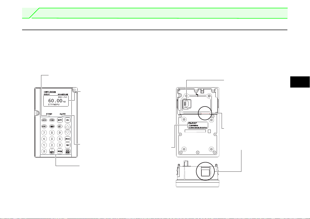
1 PRE-OPERATION INSTRUCTIONS
POWER lamp
Lit when the power turns on.
Rear
Front
Monitor
앫 Liquid crystal display
(16 characters × 4 lines with
backlight)
Interactive parameter setting
앫 Help function
앫 Trouble shooting guidance
앫 Monitor (frequency, current, pow-
er, etc.)
ALARM lamp
Lit to indicate an inverter alarm occurrence.
Operation keys
(Refer to page 4)
Connection connector
Connector to be connected
to the inverter. Connected
directly to PU connector of
the inverter
Cable connection
connector
Connect using the connection cable FR-A5 CBL
Bottom
Model
1.1 Overview
1.1.1 Appearance and parts identification
Unpack the parameter unit, check the name plate on the back, and make sure that the product has not been damaged before using
the equipment.
1
3
PRE-OPERATION INSTRUCTIONS
to
/
1.1.2 Explanation of keys
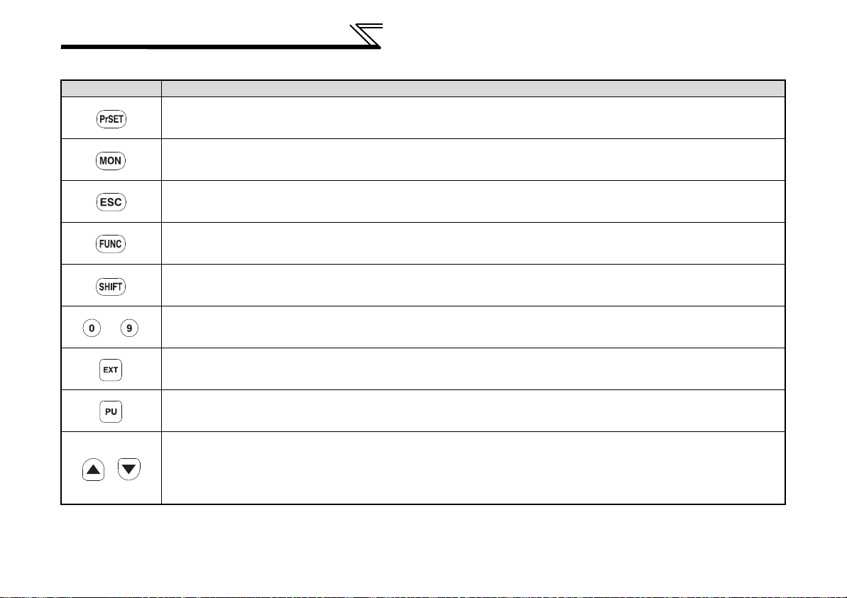
Key Description
Used to select the parameter setting mode.
Press to select the parameter setting mode.
Used to display the first priority screen.
Used to display the output frequency when making an initial setting.
Operation cancel key.
Used to display the function menu.
A variety of functions can be used on the function menu.
Used to shift to the next item in the setting or monitoring mode.
Used to enter a frequency, parameter number or set value.
Used to select the external operation mode.
Used to select the PU operation mode to display the frequency setting screen.
앫 Used to keep on increasing or decreasing the running frequency. Hold down to vary the frequency.
앫 Press either of these keys on the parameter setting mode screen to change the parameter setting value sequentially.
앫 On the selecting screen, these keys are used to move the cursor.
앫 Hold down the SHIFT-key and press either of these keys to advance or return the display screen one page.
4
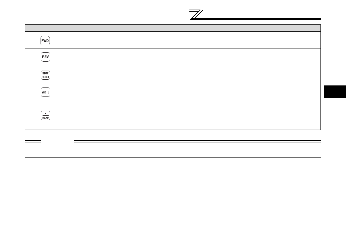
Key Description
Forward rotation command key.
Reverse rotation command key.
앫 Stop command key.
앫 Used to reset the inverter when an alarm occurs.
PRE-OPERATION INSTRUCTIONS
앫 Used to write a set value in the setting mode.
앫 Used as a clear key in the all parameter clear or alarm history clear mode.
앫 Used as a decimal point when entering numerical value.
앫 Used as a parameter number read key in the setting mode.
앫 Used as an item select key on the menu screen such as parameter list or monitoring list.
앫 Used as an alarm definition display key in the alarm history display mode.
앫 Used as a command voltage read key in the calibration mode.
CAUTION
앫 Do not use a sharp-pointed tool to push the keys.
앫 Do not press your fingers against the display.
1
5
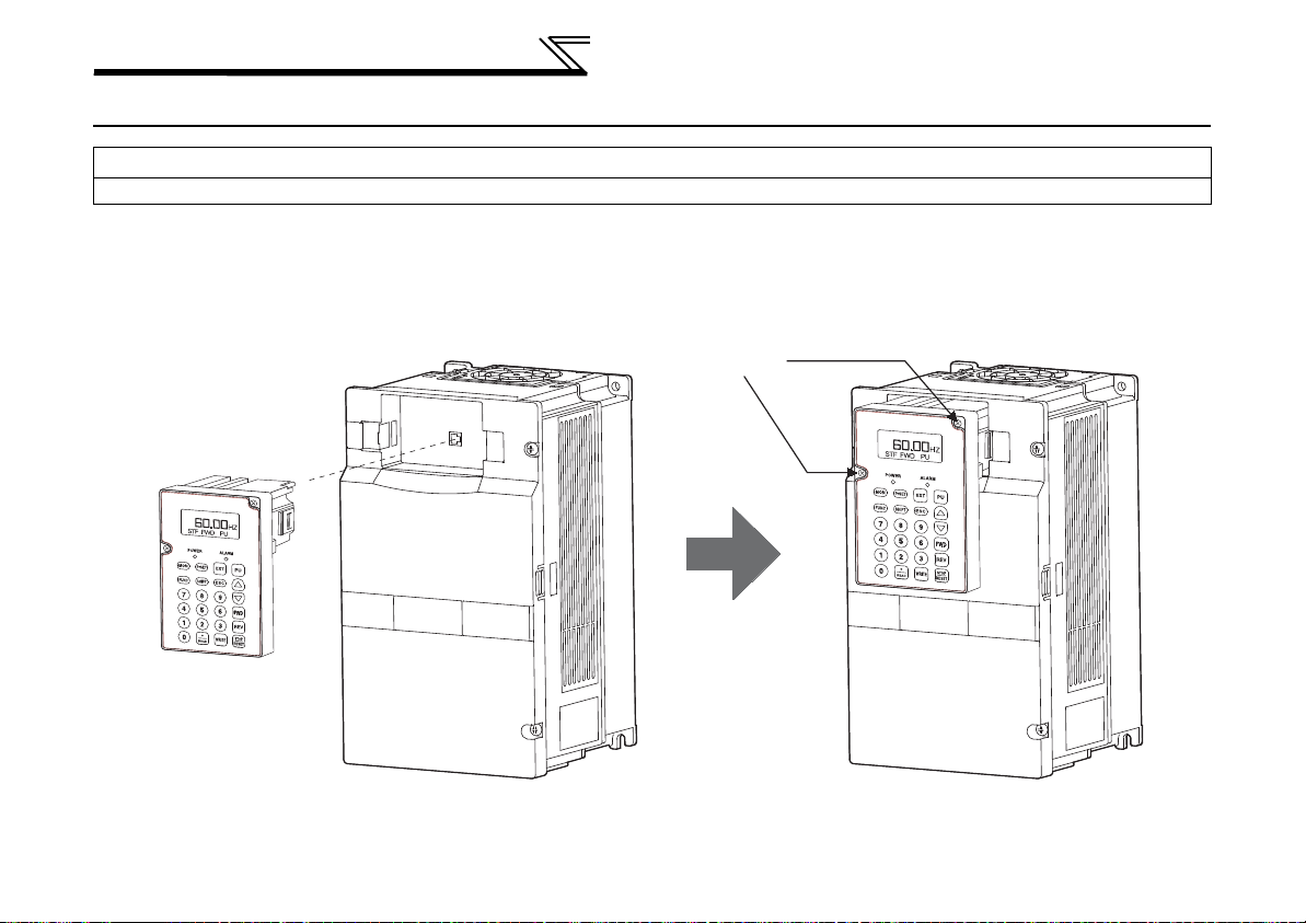
PRE-OPERATION INSTRUCTIONS
Fixed screw
1.2 Installation
b CAUTION
To ensure safety, install the FR-PU07 after switching the power of the inverter off.
1.2.1 Direct installation to the inverter
Remove the operation panel (FR-DU07).
Insert the parameter unit straight and fit it securely.
Tighten the two screws on the parameter unit to fix the unit to the inverter.
6
PRE-OPERATION INSTRUCTIONS
Stopper
FR-PU07
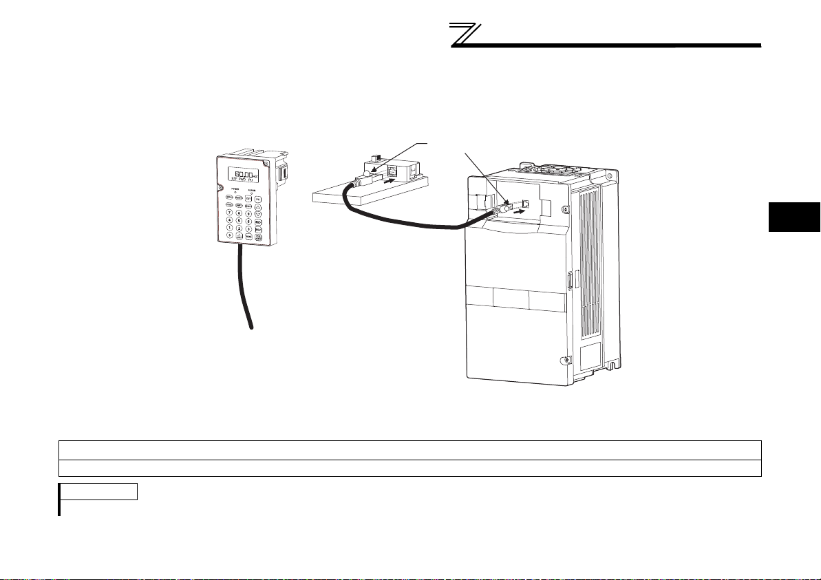
1.2.2 Installation using the connection cable
Remove the operation panel (FR-DU07).
Securely insert one end of connection cable into the PU connector of the inverter and the other end into the connection connector
of FR-PU07 along the guides until the stoppers are fixed.
1
Install the operation panel only when the front cover is installed.
REMARKS
For details of the connection cable
FR-A5 CBL, refer to the connection cable instruction manual.
b CAUTION
7
PRE-OPERATION INSTRUCTIONS
Press the hooks
Fixed screw
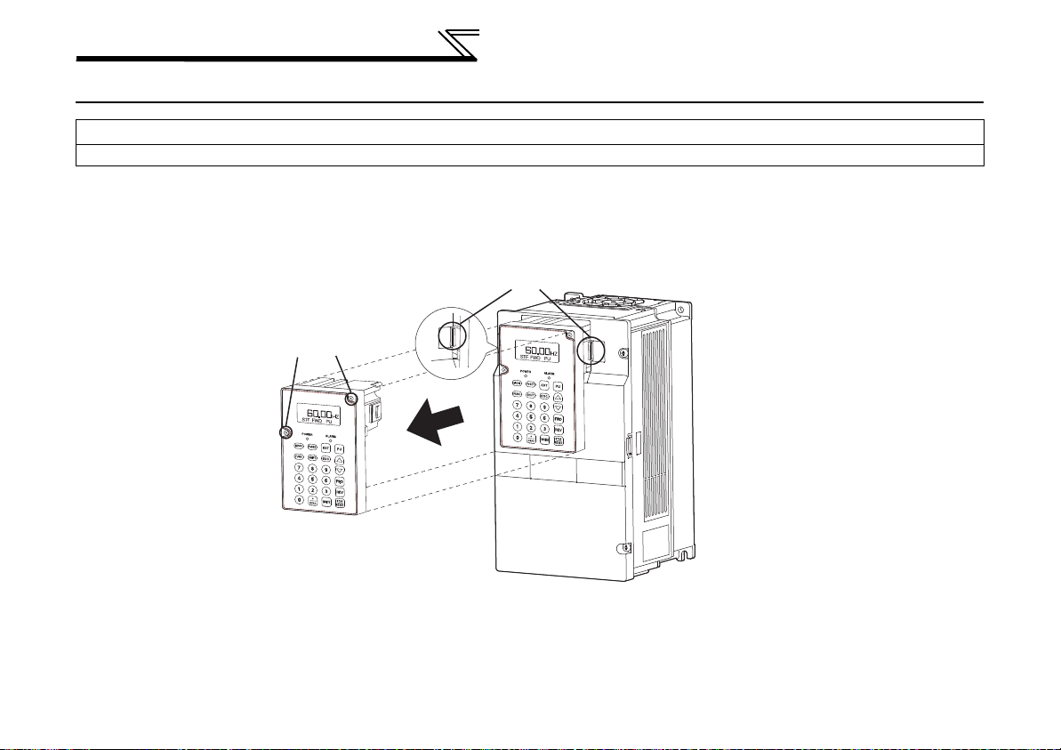
1.3 Removal
b CAUTION
To ensure safety, remove the FR-PU07 after switching the power of the inverter off.
1.3.1 Removal from the inverter
Loosen the fixed screws, hold down the right and left hooks of the FR-PU07, and then pull the parameter unit toward you.
1.3.2 Removal when the connection cable FR-A5 CBL is used
Hold down the tab (stopper) at the cable end and gently pull the plug.
8
PRE-OPERATION INSTRUCTIONS
1.4 Parameters to be Checked First
Change the following parameter settings as required. For the changing procedures, refer to page 21.
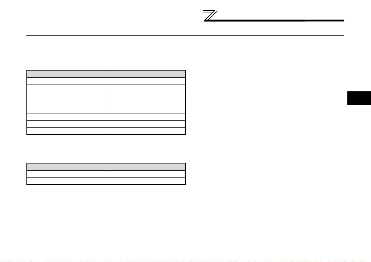
1.4.1 PU display language selection (Pr. 145)
By setting the Pr. 145 "PU display language selection" value, you can select the language displayed on the parameter unit.
Setting Display Language
0 Japanese
1 (initial value) English
2German
3 French
4 Spanish
5 Italian
6Swedish
7 Finnish
1.4.2 PU buzzer control (Pr. 990)
By setting the Pr. 990 "PU buzzer control value", you can select to either generate or mute the "beep" which sounds when you
press any of the parameter unit keys.
Setting Description
0 No buzzer sound
1 (initial value) Buzzer sound generated
1
9
PRE-OPERATION INSTRUCTIONS
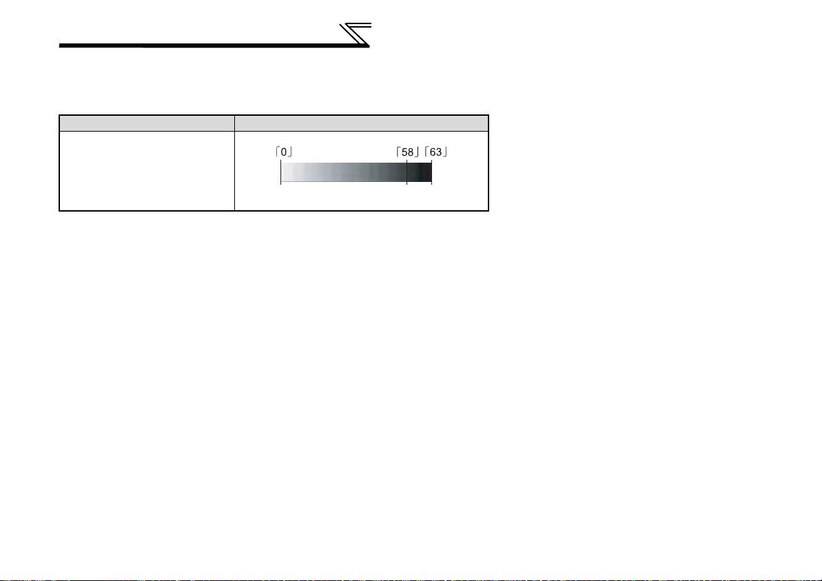
Light Initial value Dark
1.4.3 PU contrast adjustment (Pr. 991)
By setting the Pr. 991 "PU contrast adjustment value", you can adjust the contrast for the display panel of the parameter unit.
Press the WRITE-key to store the setting value.
Setting Description
0 to 63
10
2 FUNCTIONS
Main monitor
READ:List
120.00
OL
Hz
STF FWD PU
Rotation direction indication
Operating status indication
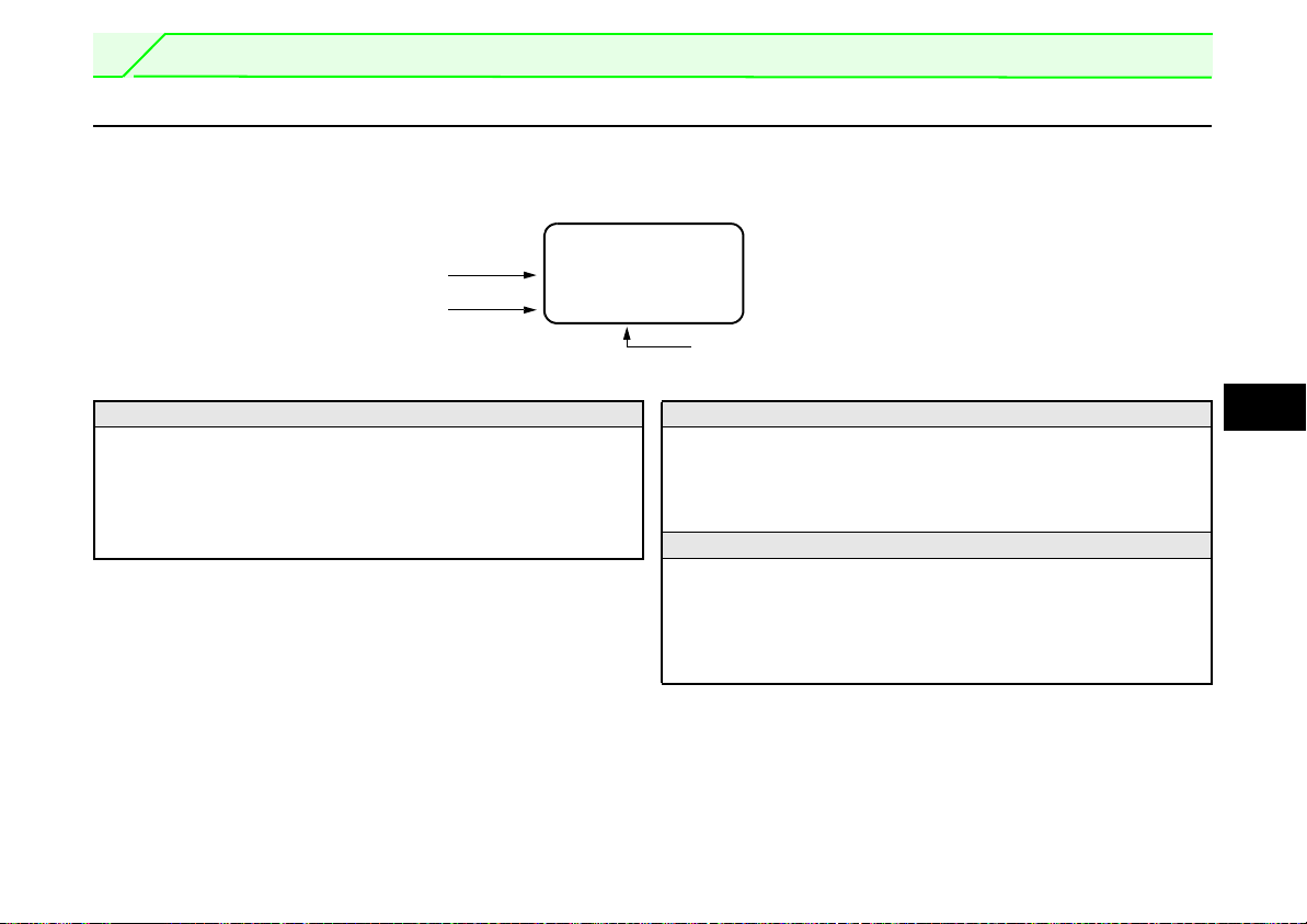
2.1 Monitoring Function
2.1.1 Display overview
Main monitor
Shows the output frequency, output current, output voltage, alarm history and other monitor data.
앫 Using the SHIFT-key to change to the next screen (refer to page 13).
앫 Using the FUNC-key to call the Function menu (refer to page 47).
앫 Using the parameter "PU main display data selection" to change
the monitor (refer to page 16).
Rotation direction indication
Display the direction (forward rotation/reverserotation) of the start command.
STF: Forward rotation
STR: Reverse rotation
---: No command or both STF and STR on
Operating status indication
Display the running status of the inverter.
STOP: During stop
FWD: During forward rotation
REV: During reverse rotation
JOGf: During jog forward rotation
JOGr: During jog reverse rotation
11
2
FUNCTIONS
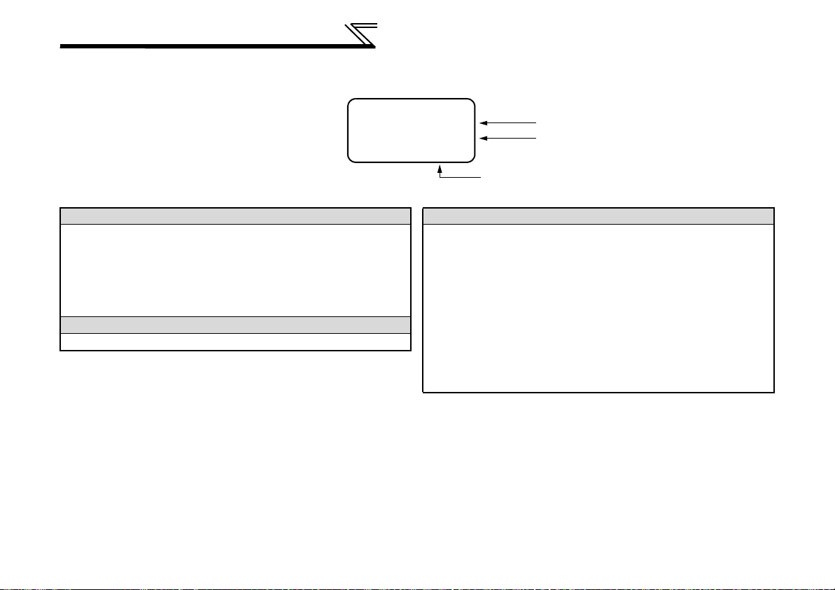
Warning indication
READ:List
120.00
OL
Hz
STF FWD PU
Unit indication
Operating mode indication
Operation mode indication
Displays the status of the operation mode.
EXT: External operation mode
PU: PU operation mode
EXTj: External jog mode
PUj: PU jog mode
NET: Network operation mode
PU+E: External/PU combined operation mode
Unit indication
Shows the unit of the main monitor.
12
Warning indication
Displays an inverter fault as an alarm. The warning type varies with the
inverter model. Refer to the inverter instruction manual for details.
OL: Overcurrent stall prevention
oL: Overvoltage stall prevention
RB: Regenerative brake pre-alarm
TH: Electronic thermal relay function pre-alarm
ZC: Zero current detection
PS: PU stop
FN: Fan fault
MT: Maintenance signal output
SL: Speed limit
CP: Parameter copy
Nothing is displayed when there is no inverter warning.
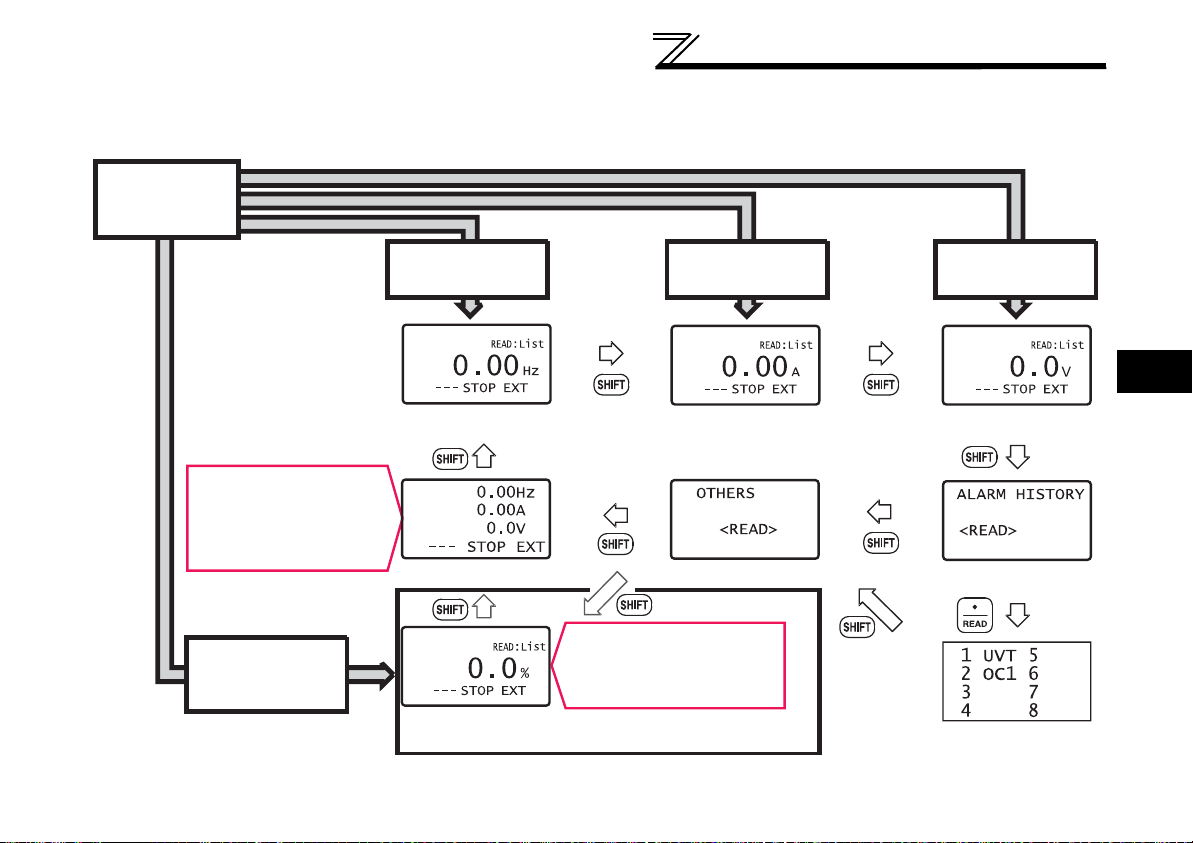
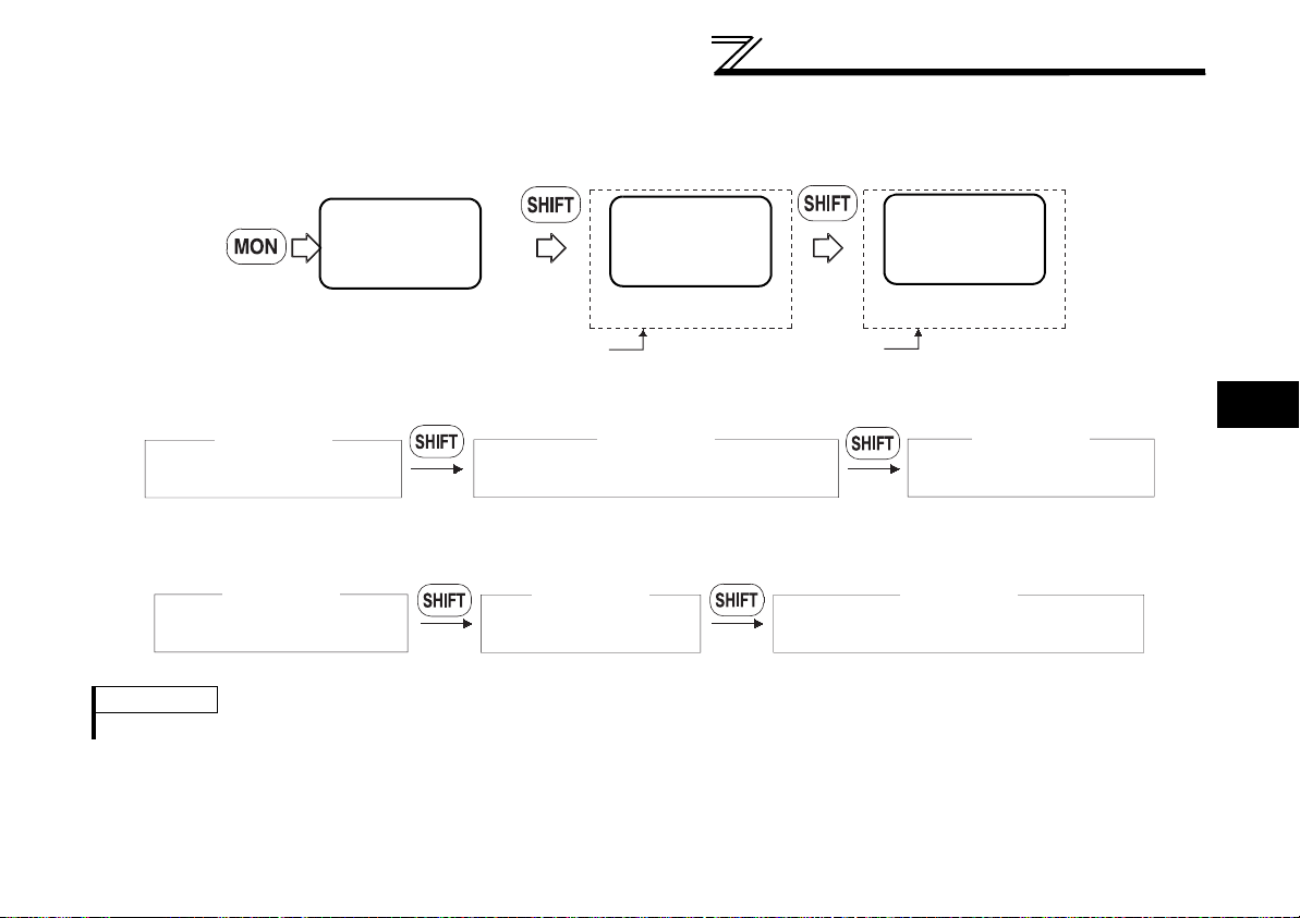
2.1.2 Using the SHIFT-key to change the main monitor
Switch power on or press
MON-key
When output frequency is the
first priority monitor (Initial
setting)
When output current is the
first priority monitor
When output voltage is the
first priority monitor
Output frequency
monitor
Output current
monitor
Output voltage
monitor
Top two monitor types of the first
priority monitor, output frequency,
output current and output voltage
are displayed in line
3-step monitor Selective monitor Alarm history monitor
When the first monitor is
other than output frequency,
output current and output
voltage
Monitor when the first monitor is other
than output frequency, output current
and output voltage.
(When electric thermal relay function load factor is set as
the first priority monitor)
When "0" (initial value) is set in the Pr. 52 "DU/PU main display data selection", merely pressing the SHIFT-key calls 6 different
monitor screens in sequence.
FUNCTIONS
2
13

FUNCTIONS
2.1.3 Setting the power-on monitor (the first priority monitor)
Set the monitor which appears first when power is switched on or MON-key is pressed.
When you press the WRITE-key with any monitor screen other than ALARM HISTORY, I/P Signal, O/P Signal, multiple simulta-
neous monitor (3-step monitor) being displayed, that screen is set as the power-on screen and will be displayed first.
14
FUNCTIONS
READ:List
0.00
A
--- STOP PU
1Frequency
2 Current
3 Voltage
4 Alarm His
9Br.Duty %
10 Therm O/L
11 Peak I
12 DC Peak V
READ:List
0.00
A
--- STOP PU
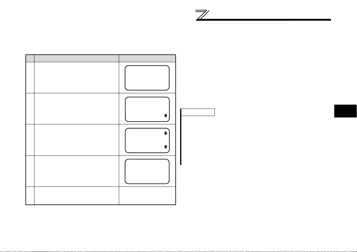
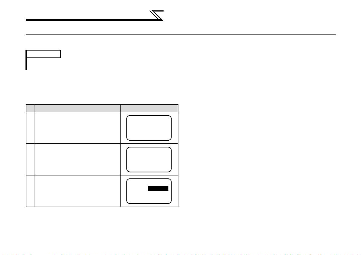
2.1.4 Using the READ-key to change the main monitor
Press the READ-key to display the monitoring list while the main monitor is displayed. Select a monitor from the monitoring list to
change the main monitor.
Example: Select the output current peak value monitor.
Description Display
Press the MON-key.
The parameter unit is placed in the
monitoring mode.
Press the READ-key.
The monitoring list appears.
Press the Cursor-keys ▲/▼ to move
the cursor to "Peak I".
Hold down the SHIFT-key and press
the Cursor-keys to shift the screen one
page.
Press the READ-key.
The output current peak is displayed.
The selective monitor screen is not yet the first priority monitor only
when the READ-key was pressed. Hence, the selected item is
erased from memory as soon as the power is switched off or
another operation mode is selected. In this case, the item must be
selected again. When you press the WRITE-key to select the first
priority screen, the selected item is stored in memory.
When the WRITE-key was pressed, the "output current peak"
selected here is first displayed with priority when the other operation
mode is switched to the monitoring mode. To give first priority to
another monitor screen, press the WRITE-key with that monitor
screen being displayed. (Refer to page 14).
REMARKS
앫 The setting can be also made from the function menu. For details re-
fer to page 41.
앫 When "Current monitor" or "Power monitor" is selected note that any
current or power not more than 5 % of the rated inverter current cannot be detected and displayed.
Example: When a small motor is used with a large-capacity inverter
(a 0.4 kW motor is used with a 55 kW inverter), power
monitor is inoperative.
2
Press the WRITE-key.
The screen in step is set as the first
priority screen.
Subsequently press the
SHIFT-key to call another
monitor screen.
15

FUNCTIONS
2.1.5 Using the parameter to change the monitor (Pr. 52)
By setting the Pr. 52 "DU/PU main display data selection", you can change the "Output current monitor" and "Output voltage monitor" monitor displays from the first priority monitor using the SHIFT-key.
Pr. 52
Inverter
FR-A700
FR-F700
InverterSetting values displayed in place of output
current monitor
17 (load meter)
18 (motor excitation current)
24 (motor load factor)
17 (load meter)
24 (motor load factor)
Setting values displayed in place of output voltage
monitor
19 (position pulse)
20 (cumulative energization time)
22 (orientation status)
23 (actual operation time)
25 (cumulative power)
32 (torque command)
33 (torque current command)
34 (motor output)
50 (power saving effect)
51 (cumulative saving power)
52 (PID set point)
53 (PID process value)
54 (PID deviation value)
20 (cumulative energization time)
23 (actual operation time)
25 (cumulative power)
50 (power saving effect)
51 (cumulative saving power)
52 (PID set point)
53 (PID process value)
54 (PID deviation value)
16
FUNCTIONS
First priority monitor
Second monitor
Third monitor
(Output frequency monitor) (Output current monitor) (Output voltage monitor)
READ:List
0.00
Hz
--- STOP EXT
READ:List
120.00
A
--- STOP EXT
READ:List
0.00
V
--- STOP EXT
First priority monitor Second monitor
Third monitor
Output frequency monitor
Monitor of the set value "17, 18, 24"
Output voltage monitor
Third monitor
Output frequency monitor Output current monitor
Monitor of the set value "19 to 23, 25"
Second monitorFirst monitor
Factory setting
The monitor displayed at powering on is the first priority monitor. Refer to page 14 for the setting method of the first priority monitor.
For the set value of "17, 18, 24", their monitors are displayed at the second monitor instead of output current monitor.
For the set value of "19 to 23, 25, 32 to 34, 50 to 54", their monitors are displayed at the third monitor instead of output voltage
monitor.
REMARKS
The setting range of Pr. 52 "DU/PU main display data selection" differs according to the inverter. Refer to the inverter instruction manual for details.
17
2
FUNCTIONS
Freq Set
SET 0.00Hz
0~400Hz
Freq Set
SET 0.00Hz
50.00Hz
0~400Hz
Freq Set
SET
50.00Hz
Completed
2.2 Frequency Setting
The frequency in PU operation mode and external/PU combined operation mode (Pr. 79 = "3") can be set.
REMARKS
When changing the operation mode from external operation mode to PU operation mode, operation mode can not be changed if the external starting
signal (STF or STR) is on.
2.2.1 Direct setting
Directly enter a frequency setting using the number keys.
Example: Operation procedure (Changing from 0 Hz setting to
50 Hz setting)
Description Display
Press the PU-key.
The frequency setting screen appears.
Enter 50 Hz using the number keys.
Press the WRITE-key.
The 50 Hz setting is complete.
If you entered an incorrect value, press the ESC-key to return to the
pre-entry state.
18
 Loading...