

Mitsubishi Electric FR-PU04, FR-PU04V Instruction Manual

INVERTER
Option unit
FR-PU04
FR-PU04V
INSTRUCTION MANUAL
Parameter unit
PARAMETER UNIT
FR-PU04
STF FWD PU
SETMON
EXT
PU
ESCHELP SHIFT
789
456
1 2
0
FWD
REV
3
STOP
WRITE
READ
RESET
PRE-OPERATION
INSTRUCTIONS
FUNCTIONS
HELP
OPERATION
CHECK FIRST WHEN YOU
HAVE A TROUBLE
SPECIFICATIONS
1
2
3
4
5
6
Thank you for choosing the Mitsubishi inverter option unit.
WARNING
CAUTION
This instruction manual gives handling information and
precautions for use of this equipment. Incorrect handling might
cause an unexpected fault. Before using the equipment, please
read this manual carefully to use the equipment to its optimum.
Please forward this manual to the end user.
This section is specifically about
safety matters
Do not attempt to install, operate, maintain or inspect this
product until you have read through this instruction manual and
appended documents carefully and can use the equipment
correctly. Do not use this product until you have a full knowledge
of the equipment, safety information and instructions.
In this instruction manual, the safety instruction levels are
classified into "WARNING" and "CAUTION".
Assumes that incorrect handling
may cause hazardous conditions,
resulting in death or severe injury.
Assumes that incorrect handling
may cause hazardous conditions,
resulting in medium or slight injury,
or may cause physical damage only.
Note that the CAUTION level may lead to a serious
consequence according to conditions. Please follow the
instructions of both levels because they are important to
personnel safety.
SAFETY INSTRUCTIONS
1. Electric Shock Prevention
WARNING
While the inverter power is ON, do not open the front cover. Do
not run the inverter with the front cover removed.
Otherwise you may access the exposed high voltage terminals
or the charging part of the circuitry and get an electric shock.
Before starting wiring or inspection, check that the operation
panel indicator is OFF, wait for at least 10 minutes after the
power supply has been switched OFF, and check that there are
no residual voltage using a tester or the like. The capacitor is
charged with high voltage for some time after power OFF and it
is dangerous.
Any person who is involved in the wiring or inspection of this
equipment should be fully competent to do the work.
Always install the inverter before wiring. Otherwise, you may
get an electric shock or be injured.
Operate the keys with dry hands to prevent an electric shock.
A-1
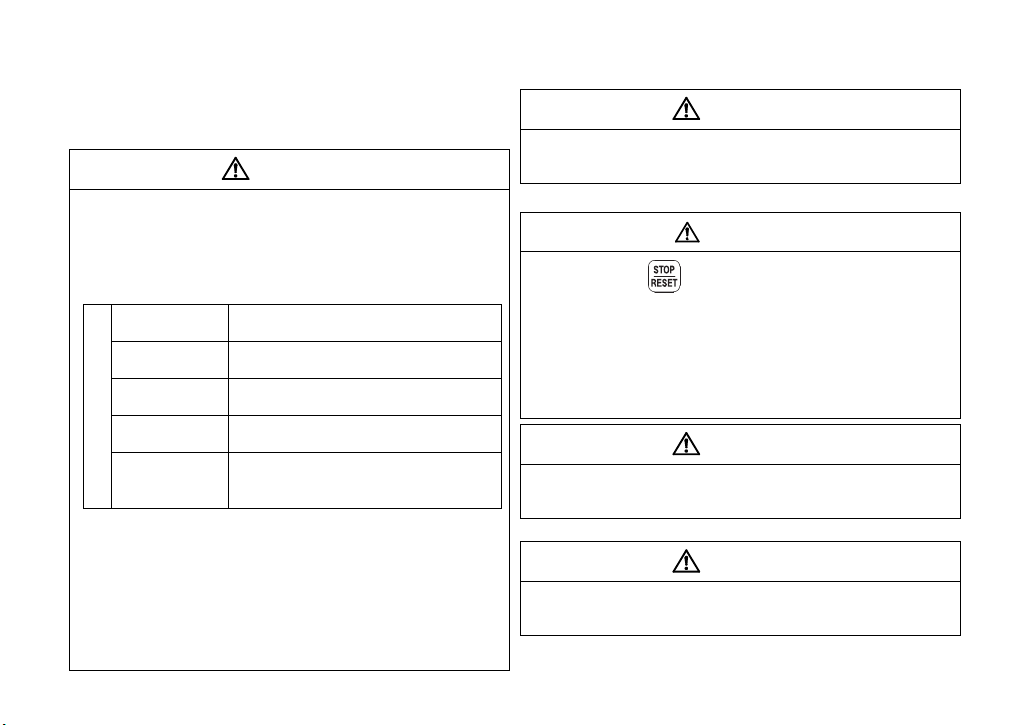
2. Additional Instructions
Environment
Surrounding air
temperature
-10C to +50C (non-freezing)
Ambient
humidity
90%RH or less (non-condensing)
Storage
temperature
-20C to +65C*
Ambience
Indoors (free from corrosive gas,
flammable gas, oil mist, dust and dirt)
Altitude,
vibration
Maximum 1000m above seal level,
5.9m/s
2
or less at 10 to 55Hz (directions
of X, Y, Z axes)
To prevent injury, damage or product failure, please note the
following points.
(1) Transportation and mounting
CAUTION
Do not install and operate the parameter unit (FR-PU04/PU04V)
if it is damaged or has parts missing.
Do not stand or rest heavy objects on this equipment.
Check the inverter mounting orientation is correct.
The parameter unit (FR-PU04/PU04V) is a precision device. Do
not drop it or subject it to impact.
Use the inverter under the following environmental conditions:
*Temperatures applicable for a short time, e.g. in transit.
If halogen-based materials (fluorine, chlorine, bromine, iodine,
etc.) infiltrate into a Mitsubishi product, the product will be
damaged. Halogen-based materials are often included in
fumigant, which is used to sterilize or disinfest wooden packages.
When packaging, prevent residual fumigant components from
being infiltrated into Mitsubishi products, or use an alternative
sterilization or disinfection method (heat disinfection, etc.) for
packaging. Sterilization of disinfection of wooden package should
also be performed before packaging the product.
A-2
(2) Test operation and adjustment
CAUTION
Before starting operation, confirm and adjust the parameters.
A failure to do so may cause some machines to make
unexpected motions.
(3) Usage
WARNING
Since pressing key may not stop output depending on
the function setting status, provide a circuit and switch
separately to make an emergency stop (power OFF,
mechanical brake operation for emergency stop, etc).
Make sure that the start signal is off before resetting the inverter
alarm. A failure to do so may restart the motor suddenly.
Do not modify the equipment.
Do not perform parts removal which is not instructed in this
manual. Doing so may lead to fault or damage of the inverter.
CAUTION
When parameter clear or all parameter clear is performed, each
parameter returns to the factory setting. Re-set the required
parameters before starting operation.
(4) Corrective actions for alarm
CAUTION
Provide safety backup devices, such as an emergency brake,
to protect machines and equipment from hazard if the
parameter unit (FR-PU04/PU04V) becomes faulty.
(5) Disposal
CAUTION
Treat as industrial waste.
(6) General instruction
All illustrations given in this manual may have been drawn with
covers or safety guards removed to provide in-depth description.
Before starting operation of the product, always return the covers
and guards into original positions as specified and operate the
equipment in accordance with the manual.
A-3

— CONTENTS —
INTRODUCTION 1
1 PRE-OPERATION INSTRUCTIONS 3
1.1 Unpacking and Product Confirmation .............................................................................................3
1.1.1 Unpacking confirmation..................................................................................................................................3
1.1.2 Appearance and parts identification...............................................................................................................4
1.1.3 Explanation of keys ........................................................................................................................................5
1.2 Installation and Removal of FR-PU04/PU04V..................................................................................7
1.2.1 Direct installation to the inverter ..................................................................................................................... 7
1.2.2 Removal from the inverter .............................................................................................................................. 8
1.2.3 Installation using the connection cable (FR-CB2) ..........................................................................................9
1.2.4 Removal when the connection cable (FR-CB2) is used...............................................................................10
1.3 Parameters to be Checked First.....................................................................................................11
1.3.1 PU display language selection (Pr. 145) ......................................................................................................11
1.3.2 PU buzzer control (Pr. 990) .......................................................................................................................... 12
1.3.3 PU contrast adjustment (Pr. 991) ................................................................................................................. 12
2 FUNCTIONS 13
2.1 Monitoring Function ........................................................................................................................13
2.1.1 Display overview...........................................................................................................................................13
2.1.2 Using "SHIFT" to change the main monitor .................................................................................................. 15
I

2.1.3 Setting the power-ON monitor (the first priority monitor) ..............................................................................16
2.1.4 Using "READ" to change the main monitor .................................................................................................. 17
2.1.5 Using the parameter to change the monitor (Pr. 52) ....................................................................................18
2.2 Frequency Setting............................................................................................................................20
2.2.1 Direct setting................................................................................................................................................. 20
2.2.2 Step setting...................................................................................................................................................21
2.2.3 Precautions for frequency setting................................................................................................................. 22
2.3 Setting and Changing the Parameter Values ................................................................................23
2.3.1 Specifying the parameter number to change the set value .......................................................................... 23
2.3.2 Selecting the parameter from functional list to change the set value ...........................................................24
2.3.3 Selecting the parameter from parameter list to change the set value ..........................................................26
2.3.4 Selecting the parameter from User List to change the set value..................................................................27
2.3.5 Precautions for setting write ......................................................................................................................... 28
2.4 User Group Function .......................................................................................................................29
2.4.1 Registering the parameters to user group.................................................................................................... 30
2.4.2 Deleting the parameters from user group ..................................................................................................... 31
2.4.3 Confirming the parameters registered to user group.................................................................................... 31
2.5 Calibration of the Meter (Frequency Meter)...................................................................................32
2.5.1 Calibration of the FM terminal ...................................................................................................................... 32
2.5.2 Calibration of the AM terminal ..................................................................................................................... 33
2.6 Adjustment of the Frequency Setting Signals "Bias" and "Gain" ..............................................36
2.6.1 Adjustment procedure .................................................................................................................................. 36
3HELP 42
II

3.1 Overview of the Help Menu .............................................................................................................42
3.1.1 Help menu .................................................................................................................................................... 42
3.1.2 Help menu transition.....................................................................................................................................44
3.2 Operation Procedures for the Help Menu......................................................................................48
3.2.1 Monitor function ............................................................................................................................................ 48
3.2.2 Selection of PU operation (direct input)........................................................................................................ 49
3.2.3 Selection of the PU Jog operation mode ...................................................................................................... 50
3.2.4 Parameters ...................................................................................................................................................51
3.2.5 Parameter clear ............................................................................................................................................ 54
3.2.6 Alarm history.................................................................................................................................................56
3.2.7 Alarm clear ................................................................................................................................................... 57
3.2.8 Inverter reset ................................................................................................................................................ 58
3.2.9 Troubleshooting ............................................................................................................................................ 59
3.2.10 Terminal assignment (Selectop)................................................................................................................... 63
3.2.11 Option ........................................................................................................................................................... 64
3.2.12 Multiple copies.............................................................................................................................................. 65
3.3 Other Precautions............................................................................................................................70
3.3.1 Precautions for parameter unit operation .................................................................................................... 70
4 OPERATION 71
4.1 How to Select the Operation Mode.................................................................................................71
4.1.1 Switching from External operation mode [EXT] to PU operation mode [PU]................................................71
4.1.2 Switching from PU operation mode [PU] to External operation mode [EXT]................................................71
4.1.3 Switching to the External / PU combined operation mode ...........................................................................72
III

4.2 How to Operate PU Operation ........................................................................................................74
4.2.1 Normal operation ..........................................................................................................................................74
4.2.2 PU Jog operation .......................................................................................................................................... 75
4.3 Combined Operation (Operation Using External Input Signals and PU)....................................76
4.3.1 Entering the start signal from outside and setting the running frequency from the PU (Pr. 79 = 3) .............76
4.3.2 Entering the running frequency from outside and making start and stop from the PU (Pr. 79 = 4)..............77
4.3.3 Entering the start signal and multi-speed signal from outside and
setting multiple speeds from the parameter unit........................................................................................... 78
5 CHECK FIRST WHEN YOU HAVE A TROUBLE 79
5.1 Troubleshooting...............................................................................................................................79
6 SPECIFICATIONS 80
6.1 Standard Specifications ..................................................................................................................80
6.2 Outline Drawing and Panel Cutting Drawing.................................................................................81
6.2.1 FR-PU04/PU04V outline dimension drawings .............................................................................................. 81
6.2.2 FR-PU04/PU04V enclosure cut dimensions................................................................................................. 82
APPENDIX 83
Appendix 1 Disposing of the equipment in the EU countries ..............................................................83
IV

INTRODUCTION
This product is a unit for setting inverter functions (parameters) and has the following features.
· An operation panel can be removed and a parameter unit can be connected.
· Setting such as direct input method with a numeric keypad, operation status indication, and help function are
usable.
· Eight languages can be displayed.
· Parameter setting values of maximum of three inverters can be stored.
1
HELP
123
456
789
0
EXT
PU
SETMON
ESC
SHIFT
FWD
REV
WRITE
READ
STF FWD PU
FR-PU04V
PARAMETER UNIT
RESET
STOP
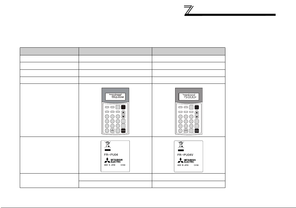
INTRODUCTION
This instruction manual uses the screens on the FR-PU04 connected to the FR-A500 series inverter for
describing the operation.
For using the FR-PU04V, some indications or terms used in this instruction manual must be replaced as
follows.
Item FR-PU04 FR-PU04V
Name Frequency, output frequency Speed, running speed
Main monitor indication 60.00Hz 1500.0r
First monitor Frequency Speed
Monitor indication F Command S Command
PARAMETER UNIT
FR-PU04
STF FWD PU
SETMON
EXT
Appearance
ESCHELP SHIFT
789
456
3
1 2
WRITE
0
READ
PU
FWD
REV
STOP
RESET
Rating plate
Te rm i na l
FM DA1
AM DA2
2

1 PRE-OPERATION INSTRUCTIONS
1.1 Unpacking and Product Confirmation
Take the parameter unit out of the package, check the unit name, and confirm that the product is as you
ordered and intact.
1.1.1 Unpacking confirmation
Check the enclosed items.
· FR-PU04/PU04V
Parameter unit
........................................................... 1
3
1
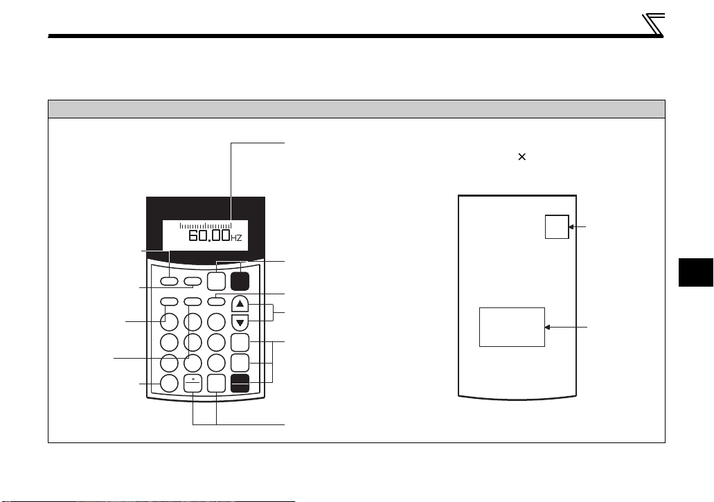
1.1.2 Appearance and parts identification
Connector
Rating
plate
STOP
RESET
1
2
3
4
56
7
89
0
EXT
PU
SETMON
ESCHELP
SHIFT
FWD
REV
WRITE
READ
PARAMETER UNIT
STF FWD PU
FR-PU04
Monitor section
●Liquid crystal screen (16 characters 4 lines,
with backlight)
Operation mode selection
key
Escape key
Frequency changing keys
Operation command keys
Write, read keys
Monitor mode
selection key
Setting mode
selection key
Help mode
selection key
Shift key
Function and
number keys
(0 to 9)
●Interactive parameter setting
●Help function,
troubleshooting guidance.
●Monitor (frequency,
current, power, etc.)
●Keys used to command
forward rotation, reverse
rotation and stop (reset at
alarm occurrence).
Front Rear
Unpack the parameter unit, check the name plate on the back, and make sure that the product has not
been damaged before using.
Unpacking and Product Confirmation
FR-PU04/PU04V
4
Unpacking and Product Confirmation
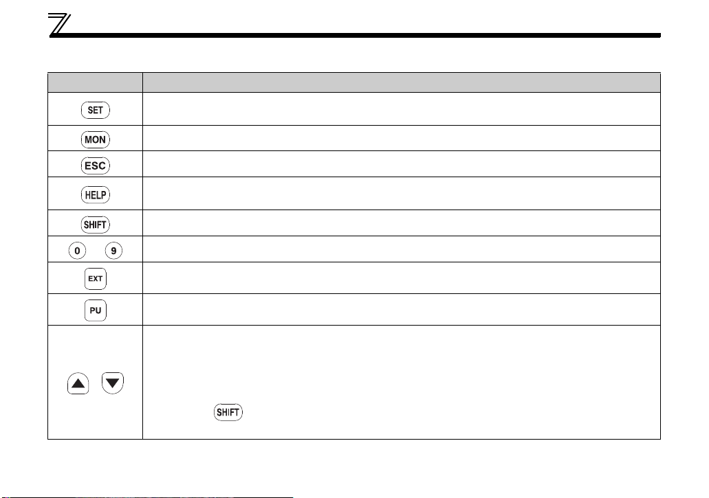
1.1.3 Explanation of keys
Key Description
· Used to select the parameter setting mode.
· Press to select the parameter setting mode.
Used to display the first priority screen.
Operation cancel key.
· Used to display the help menu.
· Various functions can be executed from the help menu.
Used to shift to the next item in the setting or monitoring mode.
to
/
Used to enter a frequency, parameter number or set value.
Used to select the External operation mode.
Used to select the PU operation mode to display the frequency setting screen.
· Used to keep on increasing or decreasing the running frequency. Hold down to change the
frequency.
· Press either of these keys on the parameter setting mode screen to change the parameter setting
value sequentially.
· On the selecting screen, these keys are used to move the cursor.
· Hold down and press either of these keys to advance or return the display screen one
page.
5
1
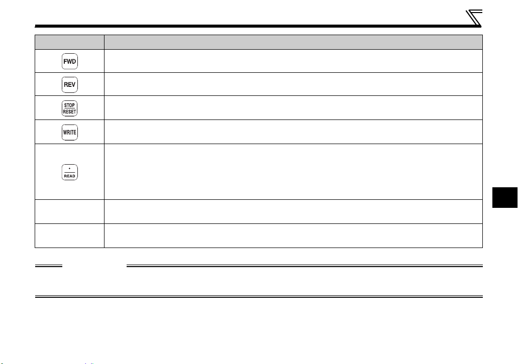
Key Description
Forward rotation command key.
Reverse rotation command key.
· Stop command key.
· Used to reset the inverter when a fault occurs.
· Used to write a set value in the setting mode.
· Used as a clear key in the all parameter clear or alarm history clear mode.
· Used as a decimal point when entering numerical value.
· Used as a parameter number read key in the setting mode.
· Used as an item select key on the menu screen such as parameter list or monitoring list.
· Used as an alarm definition display key in the alarm history display mode.
· Used as a command voltage read key in the calibration mode.
Display
Connector
16 character 4 line liquid crystal display screen shows monitoring data, such as frequency, motor
current and I/O terminal states, as well as troubleshooting guidance and other information.
Used for connection of the parameter unit with the inverter. You may either connect the unit directly
or use the connection cable (FR-CB2) for connection.
CAUTION
· Do not use a sharp-pointed tool to push the keys.
· Do not press your fingers against the display.
Unpacking and Product Confirmation
6
Installation and Removal of FR-PU04/PU04V
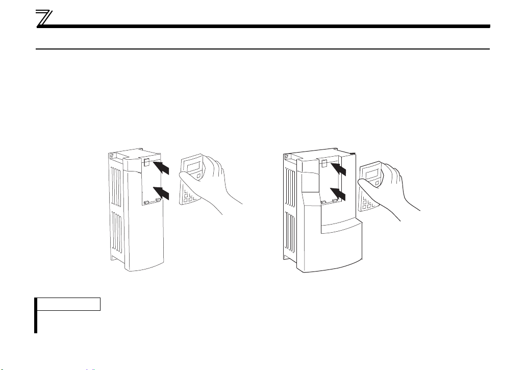
1.2 Installation and Removal of FR-PU04/PU04V
To ensure safety, install or remove the FR-PU04/PU04V only after switching the power of the inverter OFF.
1.2.1 Direct installation to the inverter
(1) Remove the operation panel (FR-DU04/DU-04-01).
(2) Insert the parameter unit straight into the position and fit it securely.
FR-PU04 FR-PU04V
FR-A500/F500 series inverter FR-V500 series inverter
REMARKS
· Direct installation of the FR-PU04 is possible only to the FR-A500/F500 series inverter. Direct installation of the FRPU04V is possible only to the FR-V500 inverter.
7
1
Installation and Removal of FR-PU04/PU04V
Hook
FR-PU04
FR-A500/F500 series inverter
FR-PU04V
FR-V500 series inverter
Hook
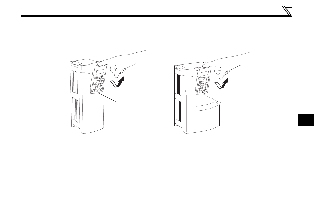
1.2.2 Removal from the inverter
Tilt the parameter unit toward the front while holding down its top button, and pull it out of the hook.
8
Junction
connector
Ta b
Ta b
Ta b
Ta b
FR-A500/F500/V500 series inverter
FR-E500 series inverter
Installation and Removal of FR-PU04/PU04V
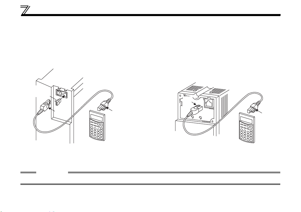
1.2.3 Installation using the connection cable (FR-CB2)
For details of the connection cable (FR-CB2), refer to the instruction manual of the FR-CB2.
Connection to the FR-A500/F500/V500/E500 series inverter
(1) Remove the operation panel.
(2) Insert the cable plugs into the connectors on the inverter and the parameter unit (FR-PU04/PU04V)
until the tabs snap into place.
CAUTION
Do not remove the inverter's front cover.
9
1
Installation and Removal of FR-PU04/PU04V
Ta b
Ta b
Connector
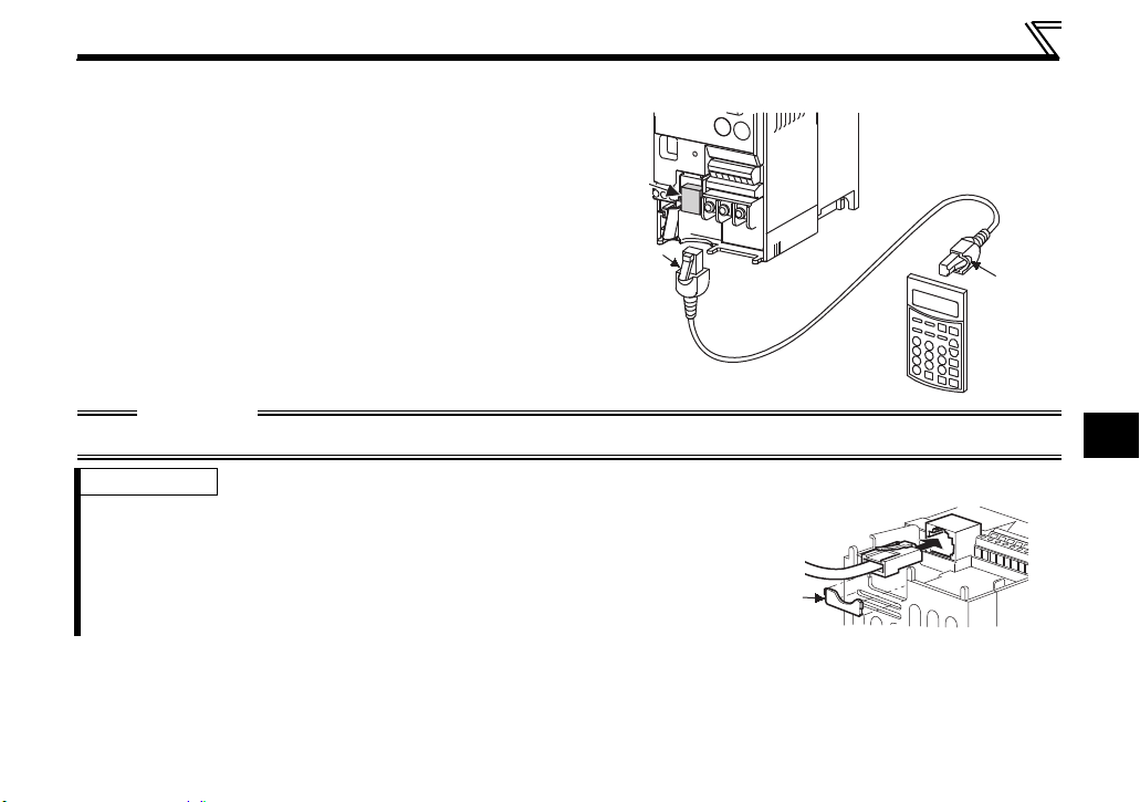
Connection to the FR-S500/F500J/C500 series inverter
(1) Remove the front cover.
(2) Insert the cable plugs into the connectors on
the inverter and the parameter unit (FRPU04/PU04V) until the tabs snap into place.
CAUTION
Do not remove the inverter's wiring cover.
REMARKS
· The cable plug can be connected after cutting off the lug of the wiring cover,
allowing the plug to be inserted and removed without removing the front
cover.
Lug
1.2.4 Removal when the connection cable (FR-CB2) is used
Hold down the tab at the cable end and gently pull the plug.
10

Parameters to be Checked First
1.3 Parameters to be Checked First
Change the following parameter settings as required.
For the changing procedures, refer to page 23.
1.3.1 PU display language selection (Pr. 145)
By setting the Pr. 145 PU display language selection value, you can select the language displayed on the
parameter unit.
Pr. 145 Setting Display Language
0 Japanese
1English
2German
3 French
4Spanish
5Italian
6 Swedish
7 Finnish
11
1
Parameters to be Checked First
1.3.2 PU buzzer control (Pr. 990)
By setting the Pr. 990 PU buzzer control value, you can select to either generate or mute the "beep" which
sounds when you press any of the parameter unit keys.
Pr. 990 Setting Description
0 No buzzer sound
1 (initial value) Buzzer sound generated
REMARKS
· Inverter alert faults with beep sounds when this parameter is set to activate the buzzer.
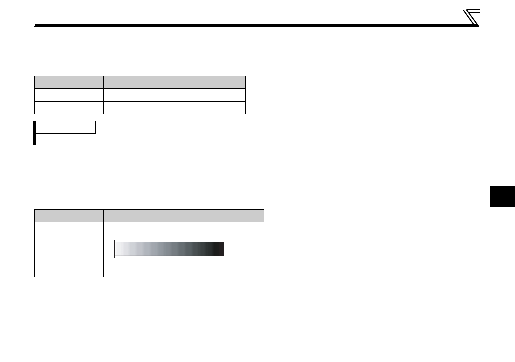
1.3.3 PU contrast adjustment (Pr. 991)
By setting the Pr. 991 PU contrast adjustment value, you can adjust the contrast for the display panel of the
parameter unit.
Pr. 991 Setting Description
「0」「63」
0 to 63
Light
Dark
12
2 FUNCTIONS
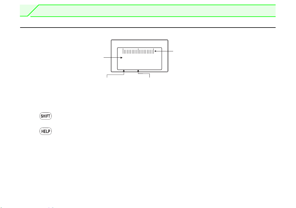
(1) Main monitor
(2)PU level meter
(for FR-A500/F500/V500)
(3) Rotation direction indication
(4) Operating status indication
120.00
OL
Hz
STF FWD PU
2.1 Monitoring Function
2.1.1 Display overview
(1) Main monitor
Shows the output frequency (Hz Out), output
current (I Out), output voltage (V Out), alarm history
and other monitor data.
· Using to change to the next screen (Refer to
page 15)
· Using to change to the next screen (Refer to
page 48)
· Using the parameter "PU main display data
selection" (Refer to page 18)
(2) PU level meter
Use Pr. 53 PU level display data selection to display
the value for the selected data on the 5-percent
scale level meter.
(For details on the parameters, refer to the
instruction manual of the inverter.)
13
(3) Rotation direction indication
Display the direction (forward rotation/reverse
rotation) of the start command.
STF: Forward rotation
STR: Reverse rotation
---: No command or both STF and STR ON
(4) Operating status indication
Display the running status of the inverter.
STOP: During stop
FWD: During forward rotation
REV: During reverse rotation
JOGf: During Jog forward rotation
JOGr: During Jog reverse rotation
ALAR: At fault occurrence
Monitoring Function
2
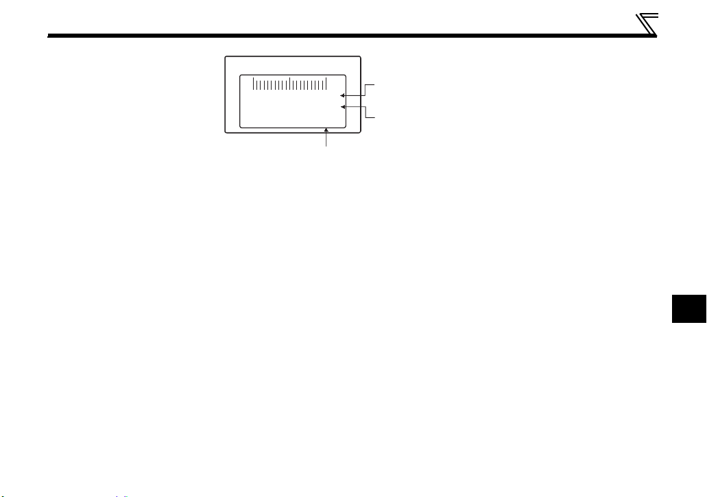
120.00
OL
Hz
STF FWD PU
(5) Operation mode indicator
(6) Unit indication
(7) Warning indication
(5) Operation mode indication
Displays the status of the operation mode.
EXT: External operation mode
PU: PU operation mode
EXTj: External Jog mode
PUj: PU Jog mode
NET: Network operation mode
PU+E: External/PU combined operation mode
PRG: Programmed operation mode
(for inverters compatible with programmed
operations only)
(6) Unit indication
Shows the unit of the main monitor.
(7) Warning indication
Displays an inverter warning.
The warning type varies with the inverter model.
Refer to the inverter instruction manual for details.
Nothing is displayed when there is no inverter
warning.
14
Monitoring Function
r
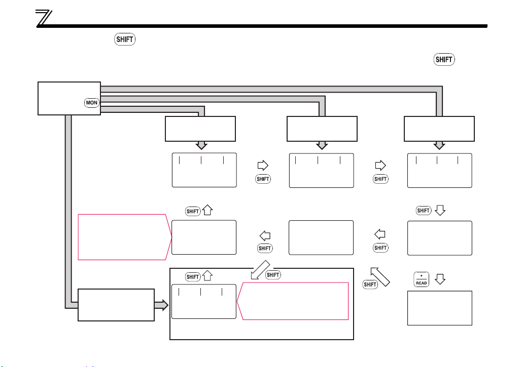
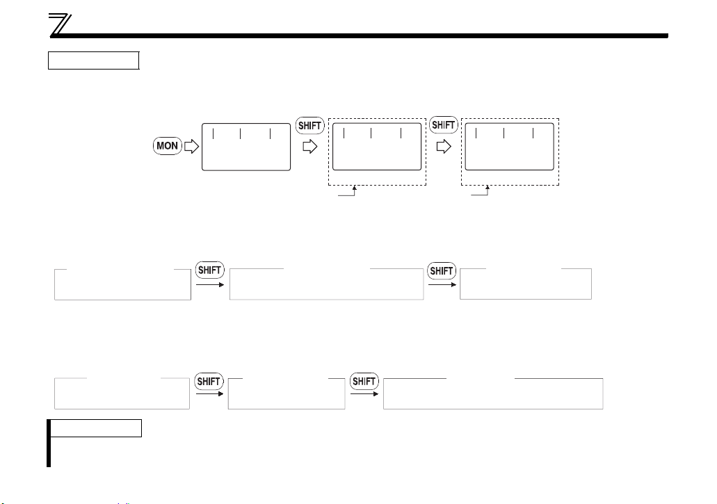
2.1.2 Using
"SHI FT"
to change the main monitor
When "0" (initial value) is set in the Pr. 52 DU/PU main display data selection, simply pressing calls 6
different monitor screens in sequence.
Switch power
ON or press
Output frequency monitor Output current monitor
First priority monitor and
top two monitors among
output current, output
frequency, and output voltage
are displayed in rows
When the first priority
monitor is other than
output frequency, output
current and output voltage
When output frequency
is the first priority
monitor (Initial setting)
0.00
--- STOP EXT
0.00Hz
0.00A
0.0V
--- STOP EXT
Hz
3-step monitor
When the first priority
0.0%
--- STOP EXT
(Example: When electric thermal relay function load
factor is set as the first priority monitor)
monitor is other than output
frequency, output current
and output voltage
When output current is
the first priority monitor
0.00
--- STOP EXT
OTHERS
<READ>
A
When output voltage is
the first priority monitor
0.0
--- STOP EXT
V
Output voltage monito
ALARM HISTORY
<READ>
Alarm history monitorSelective monitor
1 UVT 5
2 OC1 6
3 7
4 8
15

Monitoring Function
2
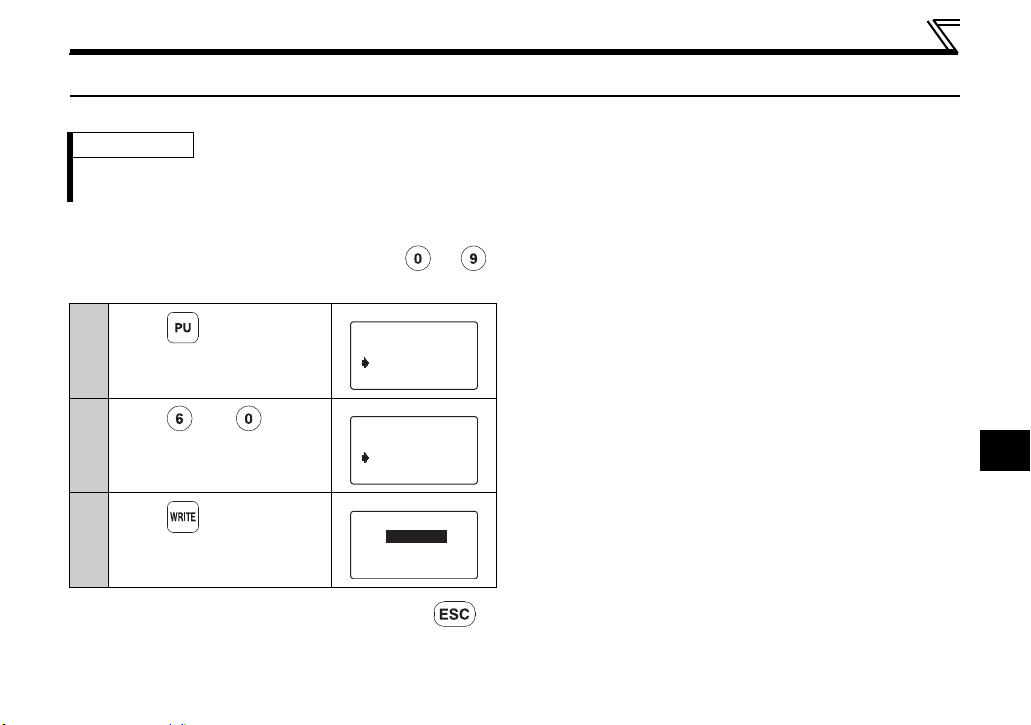
2.1.3 Setting the power-ON monitor (the first priority monitor)
Set the monitor which appears first when power is switched ON or is pressed.
When you press during any monitor screen other than ALARM HISTORY being displayed, that
screen is set as the power-ON screen and will be displayed first.
16
Monitoring Function
2 Current
3 Voltage
1 Frequency
4 Alarm His
10 Therm O/L
11 Peak I
9 Br.Duty %
12 DC Peak V
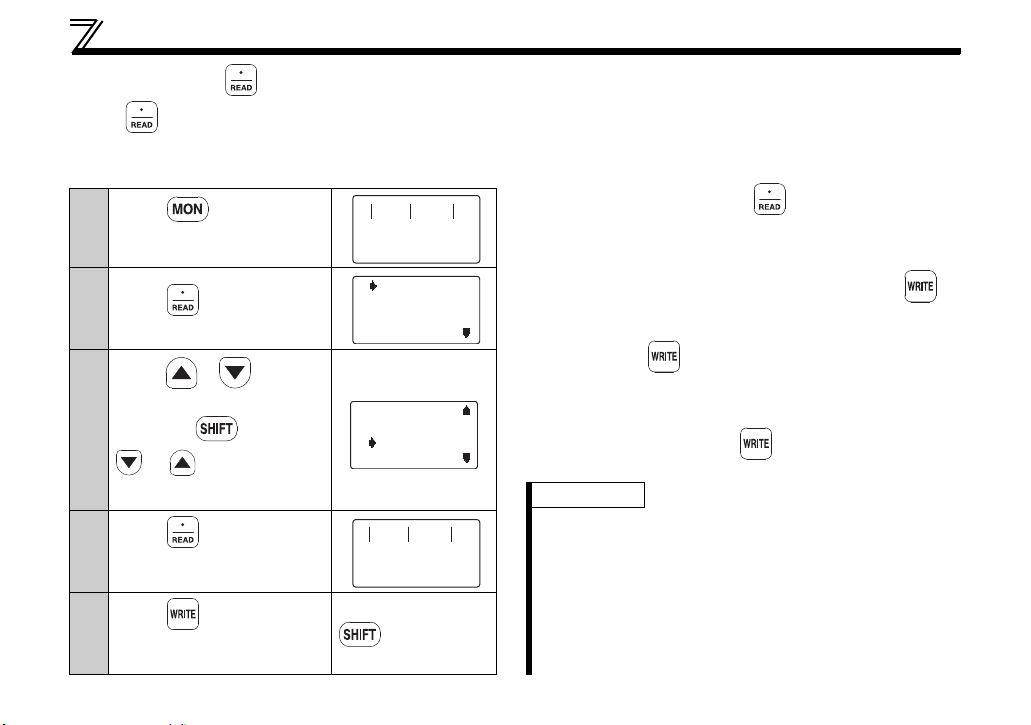
2.1.4 Using
Press to display the monitoring list while the main monitor is displayed.
Select a monitor from the monitoring list to change the main monitor.
Example: Select the output current peak value monitor.
1
2
3
4
5
17
"READ"
to change the main monitor
Press .
The parameter unit is in the
monitoring mode.
Press .
The monitoring list appears.
Press / to move
the cursor to "Peak I".
Hold down
and press
or to shift one
screen.
Press . *1
The output current peak is
displayed.
Press . *2
The screen in step 4) is set as
the first priority monitor.
0.00
--- STOP PU
0.00
--- STOP PU
A
A
Subsequently press
to call another
monitor screen.
*1 The selected monitor is not set as the first priority
monitor yet when only was pressed. Hence,
the selected monitor is erased from memory as
soon as the power is switched OFF or another
operation mode is selected. In this case, the item
must be selected again. When you press to
select the first priority screen, the selected item is
stored in memory.
*2 Pressing sets the selected "output current
peak" to be displayed in the first priority monitor
when switched to the monitoring mode from other
operation modes. To give first priority to another
monitor screen, press with that monitor screen
being displayed. (Refer to page 16)
REMARKS
· Setting from the help menu is also available. For
details refer to page 42.
· When "Current monitor" or "Power monitor" is selected,
note that any current or power not more than 5% of the
rated inverter current cannot be detected and displayed.
Example: When a small motor is rotated with a large-
capacity inverter (a 0.4kW motor is used with
a 55kW inverter), the power monitor keeps
displaying 0kW and is inoperative.

Monitoring Function
2
2.1.5 Using the parameter to change the monitor (Pr. 52)
To change the third monitor (output voltage monitor), set Pr. 52 DU/PU main display data selection.
(Note that setting "17" (load meter), "18" (Motor excitation current), and "24" (Motor load ratio) change the
output current monitor.
"Output voltage monitor" monitor displays from the first priority monitor using .
REMARKS
· The monitor items depend on the inverter. For the monitor items and descriptions, refer to the instruction manual of
each inverter.
18
Monitoring Function
First priority monitor
(Output frequency monitor) (Output current monitor) (Output voltage monitor)
First
Second
Third
Second monitor Third monitor
2)
1)
0.00
Hz
--- STOP EXT
0.00
A
--- STOP EXT
0.00
V
--- STOP EXT
First monitor
Output frequency monitor
Third monitor
Monitor of the set value "19 to 23, 25 "
Output current monitor
Second monitor
.....
Factory setting
* The monitor displayed at powering ON is the first priority monitor. Refer to page 16 for the setting method
of the first priority monitor.
1) For the set value of "17, 18, 24", their monitors are displayed at the second monitor instead of output
current monitor.
First priority monitor
Output frequency monitor
Second monitor
Monitor of the set value "17, 18, 24"
Third monitor
Output voltage monitor
2) For the set value of "19 to 23, 25
·····
", their monitors are displayed at the third monitor instead of output
voltage monitor.
REMARKS
The setting range of Pr. 52 DU/PU main display data selection differs according to the inverter.
Refer to the inverter instruction manual for details.
19
2
2.2 Frequency Setting
Freq Set
SET 0.00Hz
Freq Set
SET 0.00Hz
60Hz
60.00Hz60.00Hz
Freq Set
SET
Completed
The frequency in PU operation mode and External/PU combined operation mode (Pr. 79 = "3") can be set.
· When changing the operation mode from External operation mode to PU operation mode, operation mode cannot
2.2.1 Direct setting
Directly enter a frequency setting using to .
Operation procedure (Changing from 0Hz setting to 60Hz setting)
* If you entered an incorrect value, press to
REMARKS
be changed if the external starting signal (STF or STR) is ON.
1
Press .
The frequency setting screen
appears.
2
Press and .
Enter 60Hz.*
3
Press .
The 60Hz setting is complete.
return to the pre-entry state.
Frequency Setting
20
Frequency Setting
Freq Set
SET 0.00Hz
Freq Set
SET 0.00Hz
60Hz
60.00Hz60.00Hz
Freq Set
SET
Completed
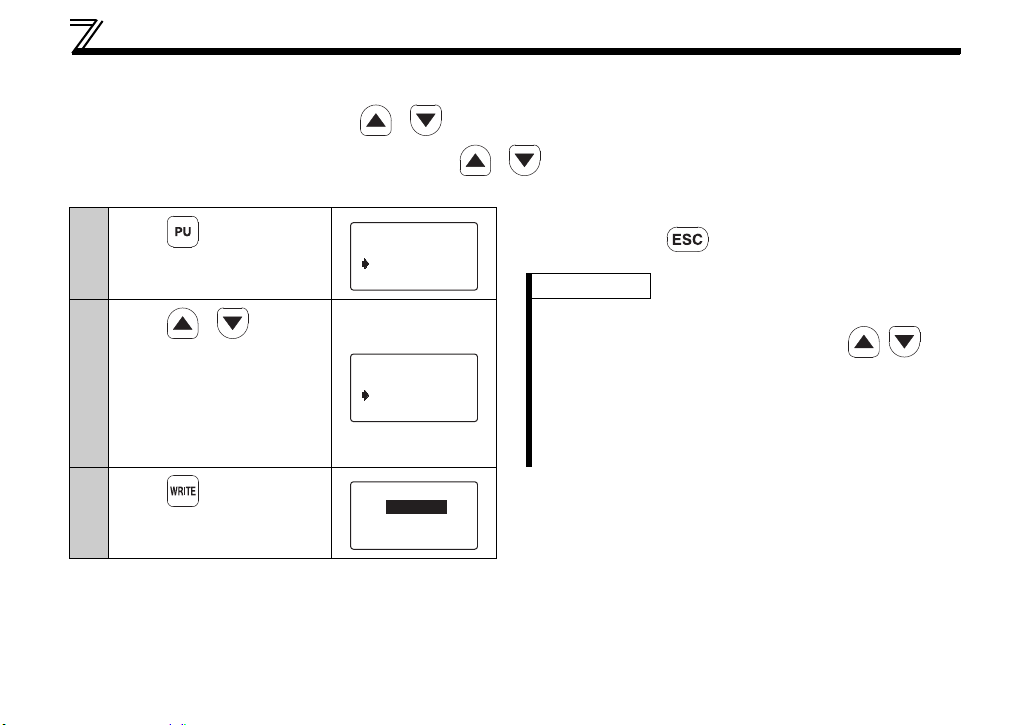
2.2.2 Step setting
Change frequency continuously using / .
You can change the frequency only while you press / . Since the frequency changes slowly at first, this setting
can be used for fine adjustment.
1
Press .
The frequency setting screen
appears.
2
Press / to enter
a desired value
(60.00Hz).*
You can set any value
between the maximum
frequency (Pr. 1 ) and
minimum frequency (Pr. 2 ).
3
Press .
The 60Hz setting is complete.
* To cancel an incorrect entry and restore the previous
screen, press .
REMARKS
· Change of frequency can be made during operation
by the step setting. However, pressing / at
monitor mode may cause actual set frequency to be
higher/lower from the indicated frequency on the
monitor. When performing the step setting at monitor
mode, make sure that output frequency is following
the set frequency.
21
 Loading...