

Mitsubishi Electric FR-PA07 Instruction Manual
INVERTER
Enclosure surface operation panel
FR-PA07 INSTRUCTION MANUAL
Thank you for purchasing the enclosure surface operation panel (FR-PA07). This instruction manual
gives handling information and precautions for use of this equipment. Incorrect handling might
cause an unexpected fault. Before using the equipment, please read this manual carefully to use the
equipment to its optimum performance.
Please forward this instruction manual to the end user.
This product is an option dedicated for the FR-E700 series.
Refer to the inverter unit's instruction manual for details on the operation panel functions, operation
methods and handling methods.
Safety precautions
z Operate the keys with dry hands to prevent an electric shock.
z Do not install and operate the enclosure surface operation panel (FR-PA07) if it is damaged
or has parts missing.
z Provide a safety backup device, such as an emergency brake, to protect machines and
equipment from hazardous conditions if the enclosure surface operation panel (FR-PA07)
becomes faulty.
z To prevent damage from static electricity, touch a piece of metal nearby before touching this
product to remove any body static electricity.
1. Instructions
For the FR-E700 series inverters manufactured during or before the period shown by the
following serial numbers, there are restrictions mentioned below.
1) Parameter copy ( ) is displayed, but parameter copy (reading, writing, or
verification) does not function. Display turns into the reading indication, but reading is
not executed. If writing or verification is executed, an error occurs.
2) Initial value change list ( ) cannot be used.
3) Easy setting mode (press and simultaneously (0.5s)) cannot be used to
change the operation mode.
4) SERIAL number check
Refer to the inverter manual for the position of the rating plate.
Rating plate example
{ { {{{{{{
Symbol Year Month Control number
SERIAL (Serial No.)
Type SERIAL number Type SERIAL number
FR-E720-0.1K to 0.75K J7{{{{{{{ FR-E740-0.4K to 7.5K D7{{{{{{{
FR-E720-1.5K to 5.5K K7{{{{{{{
FR-E720-7.5K L7{{{{{{{
FR-E720-11K, 15K G7{{{{{{{
The SERIAL consists of 1 version symbol, 2
numeric characters or 1 numeric character and
1 alphabet letter indicating year and month, and
6 numeric characters indicating control number.
Month is indicated as 1 to 9, X (October), Y
(November), and Z (December).
1
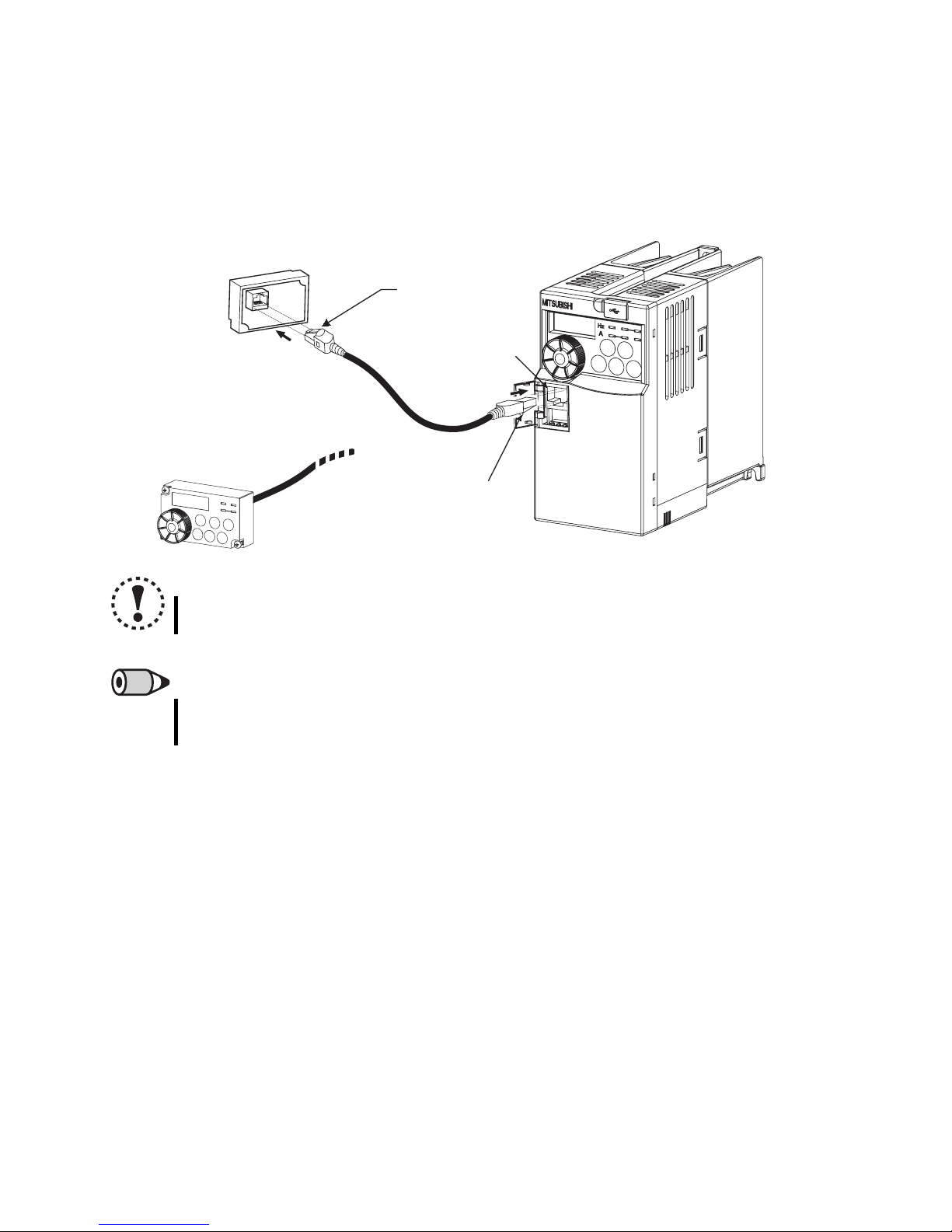
2. Connection
2.1 Installation using a connection cable (FR-CB20)
Securely insert one end of connection cable into the PU connector of the inverter and the
other end into the connection connector of the FR-PU07 along the guides until the
stoppers are fixed.
FR-PA07
Stopper
PU connector
Stopper
NOTE
y Install the FR-PA07 only when the front cover is installed.
REMARKS
y For details of the connection cable (FR-CB20), refer to the connection cable (FR-
CB20) instruction manual.
2.2 Removal when the connection cable (FR-CB20) is used
Hold down the tab (stopper) at the cable end and gently pull the plug.
2
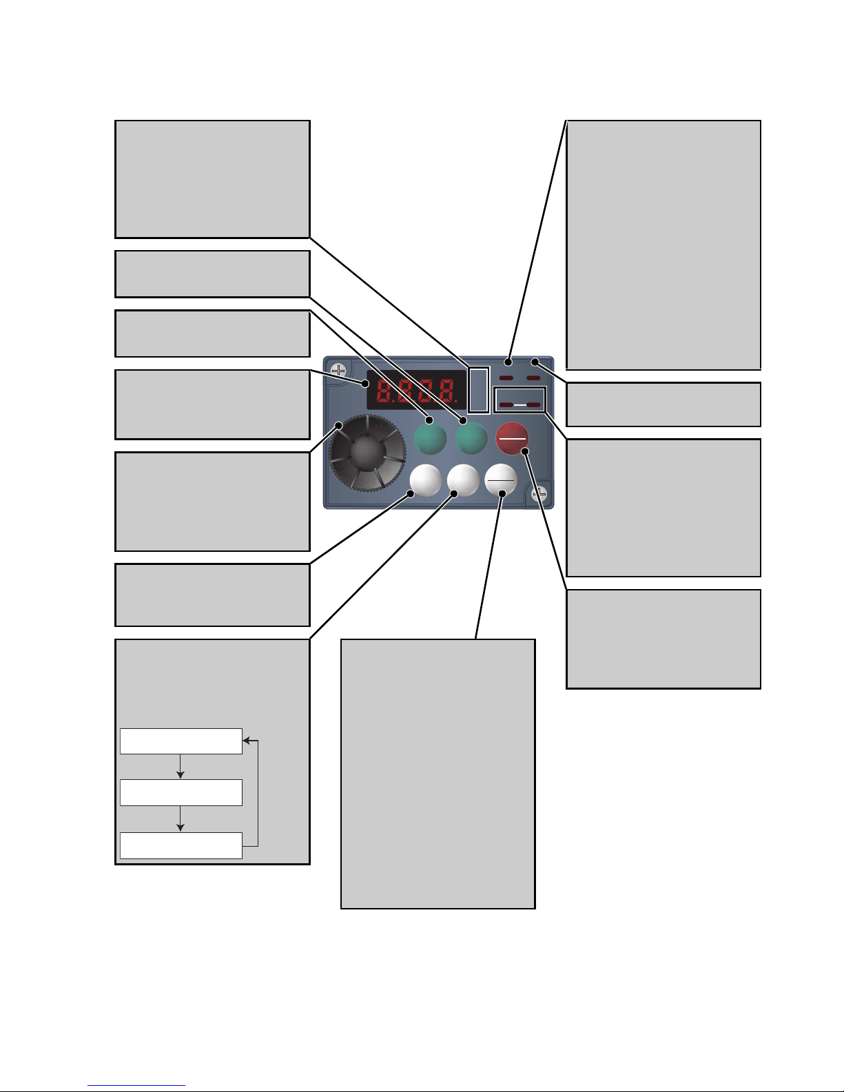
3. Names and functions of the operation panel
RUN
MON
EXT
PU
Hz
A
(FR-PA07)
Unit indication
Hz: Lit to indicate frequency.
A: Lit to indicate current.
(Off to indicate voltage and
flicker to indicate set frequency
monitor.)
Start command forward
rotation
Start command reverse
rotation
Monitor (4-digit LED)
Shows the frequency,
parameter number, etc.
Setting dial
(Setting dial: Mitsubishi inverter
dial)
Used to change the frequency
setting and parameter values.
Mode switchover
Used to change each setting
mode.
Determination of each
setting
If pressed during operation,
monitor changes as below;
Running frequency
Output current
Output voltage
RUN
Hz
PU
REV
MODE
FWD
SET
STOP
RESET
PU
EXT
Operation mode
switchover
Used to switch between the PU
and external operation mode.
When using the external
operation mode (operation
using a separately connected
frequency setting potentiometer
and start signal), press this key
to light up the EXT
indication.Change Pr. 79 setting
to change to combined mode .)
PU: PU operation mode
EXT: External operation mode
MON
EXT
Rotation direction display
On:
Indicates that forward rotation
operation is being performed.
Slow flickering (1.4s cycle):
Reverse rotation operation
Fast flickering (0.2s cycle):
y When the forward/reverse
rotation command is given
and the frequency
command is not given.
y When the MRS signal is
input.
Monitor indication
Lit to indicate monitoring mode.
Operation mode indication
PU: Lit to indicate PU operation
mode.
EXT: Lit to indicate external
operation mode.
PU, EXT: Flicker to indicate
network operation mode. *
Stop operation
Uses to stop the operation
command.
When a fault occurs, it can be
reset.
* Both PU and EXT are off on the inverters manufactured during or before the period shown by the serial
numbers described on page 1.
3
 Loading...