


INVERTER
Option unit
FR-LU08
INSTRUCTION MANUAL
LCD Operation Panel
PRE-OPERATION INSTRUCTIONS
FUNCTION AND BASIC OPERATION
MENU
CHECK FIRST WHEN YOU HAVE A
TROUBLE
SPECIFICATIONS
1
2
3
4
5

Thank you for choosing this Mitsubishi inverter option unit.
Warning
Caution
Caution
This Instruction Manual provides handling information and precautions for use of this product. Incorrect handling might cause an unexpected
fault. Before using this product, always read this Instruction Manual carefully to use this product correctly.
Please forward this Instruction Manual to the end user.
Safety instructions
Do not attempt to install, operate, maintain or inspect the product until you have read through this Instruction Manual and appended
documents carefully and can use the equipment correctly. Do not use this product until you have a full knowledge of the equipment, safety
information and instructions. In this Instruction Manual, the safety instruction levels are classified into "Warning" and "Caution".
The level may even lead to a serious consequence according to conditions. Both instruction levels must be followed
because these are important to personal safety.
Electric shock prevention
Incorrect handling may cause hazardous conditions, resulting in death or severe injury.
Incorrect handling may cause hazardous conditions, resulting in medium or slight injury, or may cause only material
damage.
Warning
While the inverter power is ON, do not open the front cover or the wiring cover. Do not run the inverter with the front cover or the wiring cover removed. Otherwise
you may access the exposed high voltage terminals or the charging part of the circuitry and get an electric shock.
Do not remove the inverter front cover even if the power supply is disconnected. The only exception for this would be when performing wiring and periodic
inspection. You may accidentally touch the charged inverter circuits and get an electric shock.
Before wiring or inspection, LED indication of the inverter unit operation panel must be switched OFF. Any person who is involved in wiring or inspection shall wait
for at least 10 minutes after the power supply has been switched OFF and check that there is no residual voltage using a tester or the like. For some time after the
power-OFF, a high voltage remains in the smoothing capacitor, and it is dangerous.
Any person who is involved in wiring or inspection of this equipment shall be fully competent to do the work.
Do not touch the operation panel or handle the cables with wet hands. Otherwise you may get an electric shock.
Do not subject the cables to scratches, excessive stress, heavy loads or pinching. Otherwise you may get an electric shock.
Additional instructions
The following instructions must be also followed. If the product is handled incorrectly, it may cause unexpected fault, an injury, or an electric
shock.
Caution
Transportation and mounting
Do not install or operate the operation panel if it is damaged or has parts missing.
Do not stand or rest heavy objects on the product.
1

Caution
Transportation and mounting
The mounting orientation must be correct.
The surrounding air temperature must be between -10 to +50°C (non-freezing). Otherwise the inverter may be damaged.
The surrounding humidity must be 90%RH or less (non-condensing). Otherwise the inverter may be damaged.
The storage temperature (applicable for a short time, such as during transit) must be between -20 to +65°C. Otherwise the inverter may be damaged.
The inverter must be used indoors (without corrosive gas, flammable gas, oil mist, dust and dirt etc.) Otherwise the inverter may be damaged.
The inverter must be used at an altitude of 2500 m or less above sea level, with 5.9 m/s2 or less vibration at 10 to 55 Hz (directions of X, Y, Z axes). Otherwise the
inverter may be damaged.
If halogen-based materials (fluorine, chlorine, bromine, iodine, etc.) infiltrate into a Mitsubishi product, the product will be damaged. Halogen-based materials are
often included in fumigant, which is used to sterilize or disinfest wooden packages. When packaging, prevent residual fumigant components from being infiltrated
into Mitsubishi products, or use an alternative sterilization or disinfection method (heat disinfection, etc.) for packaging. Sterilization of disinfection of wooden
package should also be performed before packing the product.
Trial run
Before starting operation, each parameter must be confirmed and adjusted. A failure to do so may cause some machines to make unexpected motions.
Warning
Usage
Since pressing the STOP/RESET key of the operation panel may not stop output depending on the function setting status, separate circuit and switch that make an
emergency stop (power OFF, mechanical brake operation for emergency stop, etc.) must be provided.
OFF status of the start signal must be confirmed before resetting an inverter fault. Resetting an inverter fault with the start signal ON restarts the motor suddenly.
Do not modify the equipment.
Do not perform parts removal which is not instructed in this manual. Doing so may lead to fault or damage of the product.
Caution
Usage
When parameter clear or all parameter clear is performed, the required parameters must be set again before starting operations because all parameters return to
the initial value.
Static electricity in your body must be discharged before you touch the product.
Disposal
The inverter must be treated as industrial waste.
Many of the diagrams and drawings in this Instruction Manual show the inverter without a cover or partially open for explanation. Never operate the inverter in this
manner. The cover must be reinstalled and the instructions in the Instruction Manual must be followed when operating the inverter.
2
General instruction

─ CONTENTS ─
1 PRE-OPERATION INSTRUCTIONS 5
1.1 Unpacking and checking the product............................................................................................................................5
1.2 Appearance and parts name...........................................................................................................................................5
1.3 Installation and removal..................................................................................................................................................7
1.3.1 Installing the operation panel to the inverter ......................................................................................................................... 7
1.3.2 Connecting the operation panel using a connection cable (FR-CB2)................................................................................... 9
1.3.3 Installation of a backup battery ........................................................................................................................................... 10
1.4 Items to be checked first...............................................................................................................................................11
1.4.1 Language selection............................................................................................................................................................. 11
1.4.2 PU buzzer control (Pr.990) ................................................................................................................................................. 11
1.4.3 PU contrast adjustment (Pr.991)......................................................................................................................................... 11
2 FUNCTION AND BASIC OPERATION 12
2.1 Monitor function ............................................................................................................................................................12
2.1.1 Outline of the monitor indicator........................................................................................................................................... 12
2.1.2 Using the real time clock function .......................................................................................................................................14
2.1.3 Switching the monitor data or the menu ............................................................................................................................. 15
2.1.4 Switching the main monitor data......................................................................................................................................... 16
2.1.5 Switching the main monitor data using the function menu.................................................................................................. 17
2.1.6 Switching the main monitor data using the parameter........................................................................................................17
2.1.7 Setting of the monitor data at power-ON (first priority monitor)........................................................................................... 17
2.2 Frequency setting..........................................................................................................................................................18
2.3 Faults history indicator .................................................................................................................................................18
2.4 Setting and changing the parameter values ...............................................................................................................19
2.4.1 Specifying the parameter number to change the set value................................................................................................. 19
2.4.2 Selecting the parameter from functional list to change the set value.................................................................................. 20
2.4.3 Selecting the parameter from function menu to change the set value................................................................................ 21
2.4.4 Precautions for writing the set value ...................................................................................................................................22
3

3MENU 23
3.1 Quick menu ....................................................................................................................................................................23
3.2 Function menu ...............................................................................................................................................................24
3.2.1 Parameter clear (Pr.Clear).................................................................................................................................................. 25
3.2.2 Inverter reset (INV. reset) ................................................................................................................................................... 25
3.2.3 Terminal assignment (Selectop) ......................................................................................................................................... 25
3.2.4 Parameter copy (PRCpy set).............................................................................................................................................. 26
3.2.5 Option connection status monitor (Option Instl Mntr).......................................................................................................... 28
3.2.6 USB memory device (USB Memory Device)....................................................................................................................... 29
4 CHECK FIRST WHEN YOU HAVE A TROUBLE 36
4.1 Troubleshooting ............................................................................................................................................................36
5 SPECIFICATIONS 37
5.1 Standard specifications ................................................................................................................................................37
5.2 Outline and enclosure cut dimensions........................................................................................................................38
Appendix 39
Appendix1 Disposing of the equipment in the EU countries ..........................................................................................39
4
(a)
Front view Rear view
(m)
(d)
(f)
(b)
(i)
(h)
(c)
(e)
(g)
(j) (k) (l)
(p)
(n)
(o)
1 PRE-OPERATION INSTRUCTIONS
1.1 Unpacking and checking the product
Take the operation panel out of the package, and confirm that the product is as you ordered and intact.
This product is compatible with the FR-A800 series.
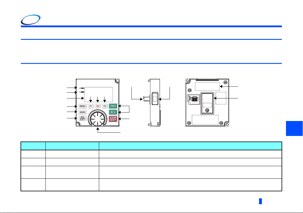
1.2 Appearance and parts name
Symbol Name Description
a Power lamp ON when the power is turned ON.
b Alarm lamp ON when an inverter alarm occurs.
cMonitor
d FWD key, REV key
Shows the frequency, parameter number, etc.
(Using Pr.52, Pr.774 to Pr.776, the monitored item can be changed.)
FWD key: Starts the forward operation.
REV key: Starts the reverse operation.
PRE-OPERATION INSTRUCTIONS
1
5

NOTE
Symbol Name Description
e STOP/RESET key
f Setting dial
g PU/EXT key Switches between the PU mode, the PUJOG mode, and the External operation mode.
h MON key Shows the first monitored item.
i MENU key
j Software key (F1)
l Software key (F3)
m Connector Connector connected to the inverter. Connect this connector to the PU connector of the inverter.
n For manufacturer setting. Do not use.
o Battery cover Remove the battery cover when replacing the backup battery for the real time clock function.
p Rating plate -
Used to stop operation commands.
Used to reset the inverter when the protective function is activated.
The setting dial is used to change the frequency and parameter settings.
Pressing the dial shows details of the faults history mode.
Displays the quick menu.
Pressing the key while the quick menu is displayed displays the function menu.
Select a guidance displayed on the monitor.k Software key (F2)
• Do not operate the keys with sharp tools.
• Do not press the LCD part.
6
PRE-OPERATION INSTRUCTIONS
1.3 Installation and removal
FastenFasten
For safety, turn OFF the inverter when installing or removing the operation panel (FR-LU08).
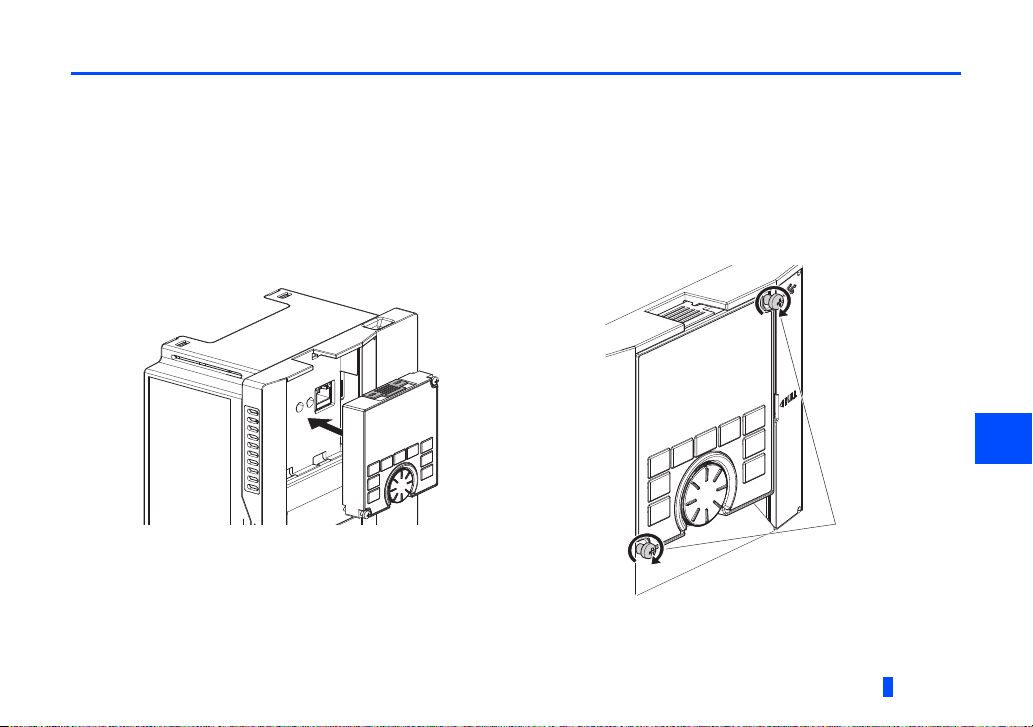
1.3.1 Installing the operation panel to the inverter
• Installation
(1) Remove the operation panel (FR-DU08) from the inverter. (For the removal of the operation panel, refer to the Instruction
Manual of the inverter.)
(2) Align the connector of the FR-LU08 with the PU connector of the inverter, and insert the operation panel. After confirming
that the operation panel is fit securely, tighten the screws. (Tightening torque: 0.40 to 0.45 N·m)
1
PRE-OPERATION INSTRUCTIONS
7
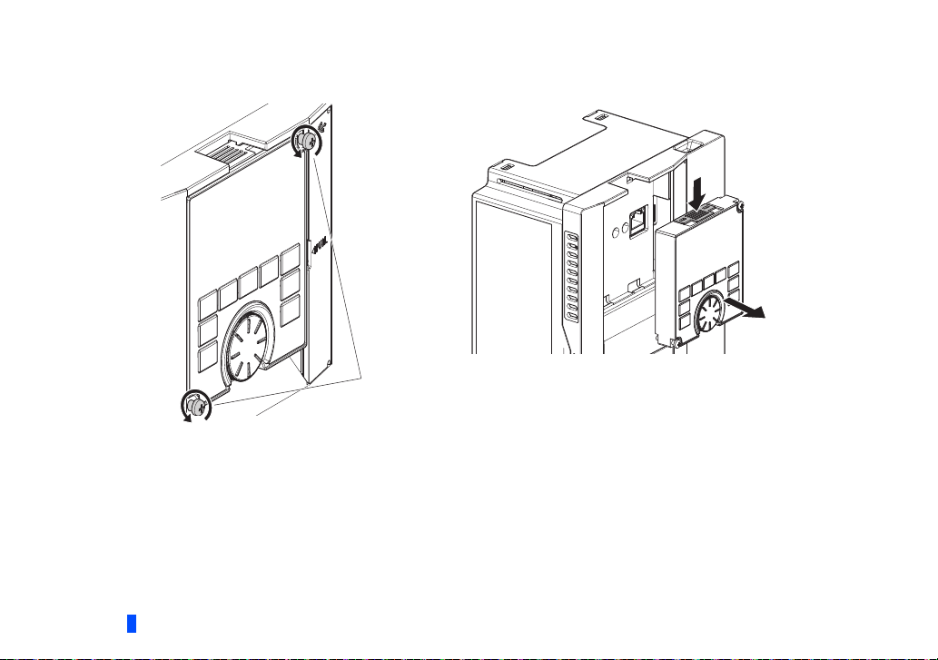
• Removal
(1) Loosen the two screws on the FR-LU08. (These screws cannot be removed.)
(2) Push the upper part of the FR-LU08, and pull out the operation panel to remove.
LoosenLoosen
8
PRE-OPERATION INSTRUCTIONS
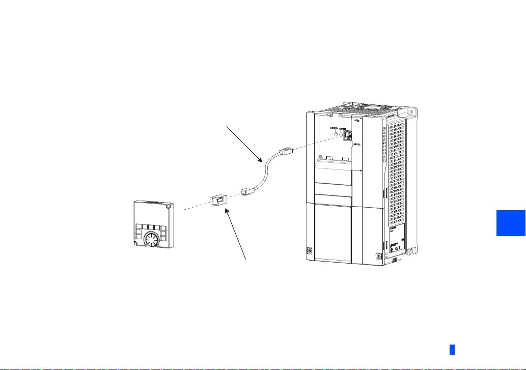
1.3.2 Connecting the operation panel using a connection cable (FR-CB2)
Parameter unit connection cable
(FR-CB2[ ]) (option)
Operation panel (FR-LU08)
Operation panel connection connector
(FR-ADP) (option)
• Installation
To connect the operation panel (FR-LU08), an optional operation panel connection connector (FR-ADP) is required.
(1) Remove the operation panel (FR-DU08) from the inverter. (For the removal of the operation panel, refer to the Instruction
Manual of the inverter.)
(2) Securely insert one end of the connection cable into the PU connector of the inverter and the other end into the connection
connector of the FR-LU08 along the guides until the stoppers are fixed.
1
• Removal
Hold down the tab (stopper) at the cable end and gently pull the pulg.
PRE-OPERATION INSTRUCTIONS
9
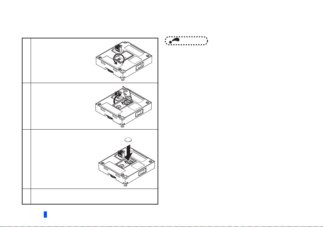
1.3.3 Installation of a backup battery
+
-
With a battery (CR1216), the FR-LU08 time count continues even if the main power of the inverter is turned OFF (real time
clock function). For the details of the real time clock function, refer to page 14.
Loosen the screw on the
battery cover, which is
located on the back side
1
of the FR-LU08.
Insert a flathead
screwdriver to the slot,
and lift the cover to
2
open.
Place the battery as shown
in the right figure.
3
Close the battery cover, and tighten the screw.
4
(Tightening torque: 0.1 to 0.3 N·m)
10
PRE-OPERATION INSTRUCTIONS
NOTE
• Do not replace the battery of the FR-LU08 while
power is ON.
1.4 Items to be checked first
NOTE
PREV SET NE XT
Language Selection
Please Select Language
English
Japanese
[0] [63]
Light
Dark
[58]
Initial value
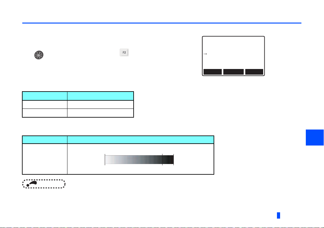
1.4.1 Language selection
At first power ON, the language selection screen appears after the corporation
logo of MITSUBISHI.
Turn to select the language, and push to set.
The interface language can be changed from the quick menu. (Refer to page 23.)
1.4.2 PU buzzer control (Pr.990)
With Pr.990 PU buzzer control, the buzzer can be set to "beep" when a key of the parameter unit is operated.
Pr.990 setting Description
0 Without buzzer
1 (initial value) With buzzer
1.4.3 PU contrast adjustment (Pr.991)
With Pr.991 PU contrast adjustment, the contrast of the display panel of the parameter unit can be adjusted.
Pr.991 setting Description
0 to 63
• For how to set parameters, refer to page 19.
(SET)
PRE-OPERATION INSTRUCTIONS
1
11
PREV
SET
NEXT
STF
STOP
PU
Hz
0. 00
Hz Out
TUNE USB - A P. RUN
12: 34
OL
▼
▲
(a)
(b)
(c)
(e)
(f)
(d)
(h)
(g)
(i)
(j)
(k)
(k)
(l)
2 FUNCTION AND BASIC OPERATION
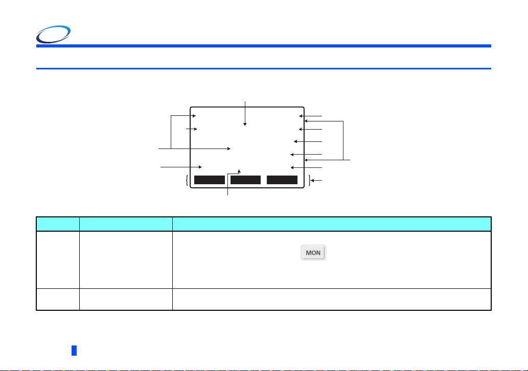
2.1 Monitor function
2.1.1 Outline of the monitor indicator
Symbol Name Description
Displays the output frequency, output current, output voltage, faults history, and other monitor data.
a Main monitor
b Rotation direction indicator
12
FUNCTION AND BASIC OPERATION
Switching the main monitor data using (Refer to page 16 .)
Switching the main monitor data using the function menu (Refer to page 17.)
Switching the main monitor data using Pr.52 Operation panel main monitor selection (Refer to
page 17.)
Displays the direction of the start command (STF: forward and STR: reverse).
(---: No start command is input, or both STF and STR are ON.)

Symbol Name Description
Displays the operating status of the inverter.
STOP: During stop
c Operating status indicator
d Clock indicator
e Tuning status indicator
f
g
h Warning indicator Displays an inverter warning.
i Unit indicator Shows the unit of the main monitor.
USB connection/password
locked
PLC function/JOG
operation indicator
FWD: During forward rotation
REV: During reverse rotation
JOGf: During JOG forward rotation
JOGr: During JOG reverse rotation
ALARM: At fault occurrence
Displays time. With a battery installed, the clock keeps working even if the main circuit power
supply is turned OFF. (Refer to page 14.)
Displays the offline auto tuning status of the inverter.
TUNE: During turning or tuning completed
TUNE highlighted and flickering: Tuning error
Displays the connection status of the USB A connector of the inverter and password function
setting status.
USB-A: USB connection recognized
USB-A highlighted: USB ready
USB-A flickering: During USB operation
LOCK: Password locked
Displays the status of the PLC function and JOG operation.
P.RUN: During stop with the PLC function enabled
P.RUN highlighted: During PLC function operation
P.RUN highlighted and flickering: Operation error in the PLC function
JOG: JOG operation enabled
2
FUNCTION AND BASIC OPERATION
13

Symbol Name Description
Displays the operation mode.
EXT: External operation mode
j Operation mode indicator
k Software key indicator Displays operations performed by pressing the F1 (left), F2 (center), or F3 (right) key.
PU: PU operation mode
EXTj: External JOG operation mode
PUj: PUJOG operation mode
NET: Network operation mode
PU+E: External/PU combined operation mode
l Scroll indicator
Displayed when the display can be scrolled by pressing .
2.1.2 Using the real time clock function
With a battery (CR1216), the FR-LU08 time count continues even if the main power of the inverter is turned OFF (real time
clock function). For how to install the backup battery, refer to page 10.
• When the battery is installed in the FR-LU08, its time is written to the inverter at power-ON (except the first power-ON after
the battery is installed).
• When the battery is not installed, the FR-LU08 reads the time from the inverter and starts counting of the clock.
14
FUNCTION AND BASIC OPERATION

2.1.3 Switching the monitor data or the menu
Pressing or switches the monitor data or the menu.
Turn ON the power,
or press .
Hz Out
0.00
PREV SET NEXT
Main monitor
12: 34
STOP PU
Quick menu
Motor setting
Hz
Auto tuning
Min. F1
PREV SET NEXT
STOP
SET SETPr SET
ALL
Quick menu Function menu
▼▼
PU
Function
MONITOR
Pr. List
Pr. Clear
PREV SET NEXT
STOP
SET
PU
2
FUNCTION AND BASIC OPERATION
15

2.1.4 Switching the main monitor data
(NEXT)
When Pr.52 Operation panel main monitor selection is set to "0", by pressing or 6 types of monitor data are
(PREV)
displayed in order.
Turn ON the power, or press .
When the output frequency
is the first monitor data
(initial setting)
Hz Out
PREV SET NEXT
First monitor Second monitor Third monitor
(NEXT)
Alarm History
1 OHT
4 OV2
2 SER
5 OV2
3 OV2
6 OV2
PREV
Faults history monitor
When the first monitor data
is other than output frequency,
output current, and output voltage
12: 34
0.00
STOP PU
(PREV)
12: 34
7 OV3
8
STOP PU
NEXT
CLR
(NEXT)
Hz
(PREV)
(PREV)
(NEXT)
When the output current
(initial setting) is the first
monitor data
I Out
PREV SET NEXT
Set Hz
60.00
PREV SET NEXT
Fourth monitor
(Displayed only when monitor data other
than the first, second, or third monitor
data is set as the first priority monitor.)
12: 34
0.00
STOP PU
12: 34
STOP PU
A
T
Hz
(NEXT)
(PREV)
(PREV)
(NEXT)
When the output voltage
(initial setting) is the first
monitor data
V Out
PREV SET NEXT
(PREV)
Hz Out
I Out
V Out
PREV SET NEXT
3-line monitor
12: 34
0.0
STOP PU
(NEXT)
12: 34
0.00Hz
0.00A
0.0V
STOP PU
V
The first monitor data and the
top two monitor data among
output current, output frequency,
and output voltage are displayed
in rows.
16
FUNCTION AND BASIC OPERATION

2.1.5 Switching the main monitor data using the function menu
NOTE
(SET)
The monitor list is displayed when the monitor selection in the function menu is selected.
If monitor data is switched from the monitor list, the new monitor data is registered and displayed in the fourth monitor.
(For the function menu, refer to page 24.)
2.1.6 Switching the main monitor data using the parameter
The monitor indicator of the output voltage monitor is switched according to the setting of Pr.52 Operation panel main
monitor selection. When "17" (load meter), "18" (motor excitation current), or "24"(motor load factor) is set in Pr.52, however,
the monitor indicator of the output current monitor is switched accordingly.
2.1.7 Setting of the monitor data at power-ON (first priority monitor)
Set the monitor data that is displayed first at power-ON or when is pressed.
While monitor data other than the faults history is displayed, press to set the monitor data to be displayed first at power-
ON.
• For details on the monitor description, refer to the Instruction Manual of the inverter.
2
FUNCTION AND BASIC OPERATION
17

2.2 Frequency setting
NOTE
BACK SET
STOP PU
Freq Set
Current 60.00Hz
60.00Hz
Preset
(NEXT)
(SET)
(BACK)
The frequency applied in the PU operation mode or external/PU combined operation mode
(Pr.79="3") can be set.
While the main monitor data is displayed, turn to input a frequency setting value and press
to confirm the setting.
(SET)
• If the external start signal (STF or STR) is ON, the External operation mode cannot be switched to the PU operation
mode.
2.3 Faults history indicator
Press while the faults history is displayed to display the details of the fault.
Details of the past eight faults can be checked by pressing .
• How to clear the faults history
18
Press while the faults history is displayed to display a confirmation screen for the faults
(CLR)
history clear. Press to clear the faults history and to return to the faults history.
FUNCTION AND BASIC OPERATION
LATEST ERR
OC During Dec
2014/02/04 10:00
Frequency 60.00Hz
BACK
STOP PU
PREV NEXT
12: 34
▼

2.4 Setting and changing the parameter values
(→)
(SET)
(SET)
BACK NEXT
STOP PU
Current 5.0 sec
180.0 sec
Completed
8 Dec. T1
Preset
Current
Preset
BACK SET NEXT
STOP PU
9 Set THM
4.25A
4.25A
0-500
For details on the parameters, refer to the Instruction Manual of the inverter.
2.4.1 Specifying the parameter number to change the set value
Example: To change the Pr.8 Deceleration time setting from 5 s to 180 s
Display the quick menu and press . The parameter
setting mode is activated.
Quick menu
Motor setting
1
Auto tuning
Min. F1
PREV SET NEXT
ALL
Turn until 8 appears.
(Or, press to move "▲" to the target digit, and select the
parameter number by turning .)
Press to display the present set value.
2
▼
STOP
SET Pr SET
PU
Parameter setting
8 Dec. T1
Current 5.0 sec
Preset
0-3600
BACK SET NEXT
(PrSET)
SETTING MODE
Pr. NO.
0000
BACK
PU
STOP
SET
PSETT
5.0 sec
STOP
PU
Turn to set the value to 180.0, and press . The set
value is changed.
3
Press to display the next parameter.
(NEXT)
4
FUNCTION AND BASIC OPERATION
2
19

2.4.2 Selecting the parameter from functional list to change the set value
(ALL)
PREV SET NEXT
SET
Pr SET
▼▼
ALL
Group parameter setting
P SET T
Category Menu
E Environment
F Acc/Dec
D Opr/Freq command
SETBACK
Motor setting
Auto tuning
Min. F1
STOP
PU
Quick menu
STOP
PU
BACK SET
STOP PU
▼
F0 Time
00 Acc/DecF
01 Incr. T
02 JOG T
(SET)
(SET)
▼
5.0 sec
180.0 sec
Completed
BACK
STOP PU
F011 Dec. T1
Current
Preset
Example: To change the F011 Deceleration time setting from 5 s to 180 s
Display the quick menu and press . The group parameter
setting mode is activated.
1
Turn to move the cursor to [F Acc/Dec], and press .
The functional list is displayed.
2
Turn to move the cursor to [0 Time], and press .
The functional list for time setting is displayed.
3
20
F Acc/Dec
0 Time
1 Pattern
2 Backlash
STOP PU
BACK SET
FUNCTION AND BASIC OPERATION
▼
(SET)
(SET)
Turn to move the cursor to [11 Dec. T1], and press .
The present set value is displayed.
4
F011 Dec. T1
Current
Preset
5.0 sec
5.0 sec
0-3600
BACK SET
STOP PU
Turn to set the value to 180.0, and press . The
set value is changed.
5

2.4.3 Selecting the parameter from function menu to change the set value
(SET)
PREV SET NEXT
Pr. List
Set Pr. List
Def. Pr. List
BACK SET
STOP
PU
(SET)
(SKIP)
PREV SET
Def. Pr. List
0 Trq. Bst
1 Max. F1
2 Min. F1
6.0
120.0
0.00
BACK SET
▼
STOP
PU
SKIP
BACK SET NEXT
STOP
PU
8 Dec. T1
Current 5.0 sec
5.0 sec
0-3600
Preset
(SET)
BACK NEXT
STOP PU
Current 5.0 sec
180.0 sec
Completed
8 Dec. T1
Preset
Current
Preset
BACK SET NEXT
STOP PU
9 Set THM
4.25A
4.25A
0-500
Example: To change the Pr.8 Deceleration time setting from 5 s (initial value) to 180 s
Display the function menu, turn to move the cursor to the
parameter, and press . [Set Pr.List] and [Def.Pr.List] are
displayed.
1
Turn to move the cursor to [Def.Pr.List], and press .
[Def.Pr.List] is displayed. Press to move the cursor
ahead 100 parameters.
2
Turn to move the cursor to [8 Dec. T1], and press .
The present set value is displayed.
3
Turn to set the value to 180.0, and press . The set
value is changed.
4
Press to display the next parameter.
(NEXT)
5
FUNCTION AND BASIC OPERATION
(SET)
2
21

NOTE
• If the parameter setting has been changed from the initial value, the set value can be changed using the change list.
(SET)
(BACK)
Turn to move the cursor to the target parameter, and press to change the set value.
2.4.4 Precautions for writing the set value
• Basically, change the parameter setting while the inverter is stopped in the PU operation mode or combined operation. The
parameter setting cannot be changed in the External operation mode or during operation. (The parameter setting can be
read regardless of the operation mode.) Note that some parameters can be written even in the External operation mode or
during operation. Refer to the Instruction Manual of the inverter used.
• In the initial setting, "0" is set in Pr.77 Parameter write selection, and thus parameters can be written only while the inverter
is stopped. (The parameters can be read even during the operation.) Note that some parameters can be always written. For
the details of Pr.77, refer to the Instruction Manual of the inverter.
• In the following cases, set values cannot be written.
1) When the parameter number selected does not exist in the parameter list
2) When a value outside the setting range is entered
• If writing fails and [Setting Error] appears, press to reset.
22
FUNCTION AND BASIC OPERATION

3 MENU
3.1 Quick menu
Frequently-used functions (parameters) can be set. For details on the parameters, refer to the Instruction Manual of the
inverter.
Quick menu Item Parameter to be set
Motor type
Current Pr.9 Electronic thermal O/L relay
Motor setting
Auto tuning
Minimum frequency - Pr.2 Minimum frequency
High speed maximum
frequency
Acceleration time - Pr.7 Acceleration time
Deceleration time - Pr.8 Deceleration time
Operation mode selection - Pr.79 Operation mode selection
Language selection - -
Voltag e
Frequency
Motor capacity Pr.80 Motor capacity
Number of motor poles Pr.81 Number of motor poles
Control method selection Pr.800 Control method selection
Auto tuning setting Pr.96 Auto tuning setting/status
- Pr.18 High speed maximum frequency
Induction motor Select the motor type and capacity.
Magnet motor Select the motor type and capacity.
Base frequency voltage Pr.19 Base frequency voltage
Rated motor voltage Pr.83 Rated motor voltage
Base frequency Pr.3 Base frequency
Rated motor frequency Pr.84 Rated motor frequency
3
MENU
23

NOTE
• Even if the PU display language has been changed using the quick menu, the Pr.145 PU display language selection
setting is not changed. In addition, changing the Pr.145 setting does not affect the language of the FR-LU08.
3.2 Function menu
Various functions can be executed.
Function menu Item
MONITOR Displays the monitor list. Monitor data can be switched. 17
Pr. List Displays the parameter change list and initial value list. Set values can be changed from each list. 21
Pr. Clear Displays the parameter clear menu. Parameter clear and all parameter clear can be executed. 25
INV. Reset Resets the inverter. 25
Selectop
PRCpy set Parameter copy (reading, writing, and verifying) can be performed. 26
S/W Version Displays the software control numbers of the inverter. -
Option Instl Mntr Displays the connection status of the option connectors 1 to 3. 28
USB Memory Device
Displays the signals assigned to the I/O terminals of the control circuit and the ON/OFF status of the
signals.
Parameter settings and projects of the PLC function can be copied and written to/from a USB memory
device, and verified.
Refer to
page
25
29
24
MENU

3.2.1 Parameter clear (Pr.Clear)
BACK
STOP PU
Selectop
RL
RM
RH
:
:
:
0
0
0
■
□
□
Indicates that the signal is ON.
Indicates that the signal is OFF.
▼
"Parameter clear" and "all parameter clear" can be executed. Set the PU operation mode before execution.
• Parameter clear ... The settings of parameters except for calibration parameters and terminal function selection parameters
are initialized.
• All parameter clear ... The settings of all the parameters, including calibration parameters and terminal function selection
parameters, are initialized.
3.2.2 Inverter reset (INV. reset)
Resets the inverter.
If the inverter's protective function has been activated and the inverter has tripped (output shutoff), inverter reset can be
executed only by pressing .
Inverter reset can also be executed by turning OFF and then ON the inverter or turning ON the RES signal. (For the details,
refer to the Instruction Manual of the inverter.)
3.2.3 Terminal assignment (Selectop)
Displays the signals assigned to the I/O terminals of the control circuit and the ON/OFF status of the signals.
The terminal status of the plug-in option can be checked if a plug-in option FR-A8AX or FR-A8AY is installed.
3
MENU
25

3.2.4 Parameter copy (PRCpy set)
BACK S E T N E X T
PRCpy set
Copyarea1
Copyarea2
Copyarea3
SET
STOP
PU
BACK
SET NEXT
Copyarea1
1 : Read VFD
2 : Write VFD
3 : Verifying
SET
STOP
PU
(SET)
BACK S E T N E X T
1 : Read VFD
Name: ABCDEFGHI
SET
STOP
PU
▲
(→)
(SET)
(SET)
(1) Copying parameter settings
Parameter settings of an inverter can be read, and the settings of maximum three inverters can be stored in the FR-LU08. The
stored parameter settings can be copied to other same-series inverters.
• Reading the parameter settings of the inverter and storing them to the FR-LU08
Connect the FR-LU08 to the inverter that contains the
1
parameters to be copied.
Display the function menu, turn to move the cursor to
2
[PRCpy set], and press .
Turn to move the cursor
to the copy area used, and
3
press .
Turn to move the cursor
to [1: Read VFD], and press
4
.
26
(SET)
MENU
(SET)
A name (up to 9 letters) can be entered for the selected area.
Turn to select "0 to 9", "A
to Z", ".", "_", "/" or "(space)".
5
Press to move the
cursor. Press after
completing the input.
A confirmation screen appears
for overwriting the selected
area. Press to execute
6
the copy.
1 : Read VFD ABCDEFGHI
Overwrite Area 1
SET : Exec
BACK : Cancel
STOP
BACK
SETSET SETSET
PU
SET

• Writing the parameter settings stored in the FR-LU08 to an inverter
(SET)
(SET)
BACK S E T N E X T
Copyarea1 ABCDEFGHI
1 : Read VFD
2 : Write VFD
3 : Verifying
SET
STOP
PU
BACK
SET
2 : Write VFD ABCDEFGHI
Area 1 to VFD
SET : Exec
BACK : Cancel
SETSET SETSET
STOP PU
(SET)
(
RESET
)
Connect the FR-LU08 to the inverter to which the parameters
1
are to be written.
Display the function menu, turn to move the cursor to
2
[PRCpy set], and press .
Turn to move the cursor
to the copy area used, and
3
press .
Turn to move the cursor
to [2: Write VFD], and press
4
5
.
(SET)
A confirmation screen
appears for writing the
parameters. Press to
write the parameters.
PRCpy set
Copyarea1
Copyarea2
Copyarea3
PREV SET NEXT
KBACK
ABCDEFGHI
STOP
SET
PU
Press to reset the
inverter.
6
2 : Write VFD ABCDEFGHI
Writing
Completed
Please Reset
BACK S E T
STOP PU
SETET
RESET
MENU
3
27

(2) Verifying the parameters
NOTE
BACK
SET NEXT
Copyarea1 ABCDEFGHI
1 : Read VFD
2 : Write VFD
3 : Verifying
SET
STOP
PU
(SET)
SET
3 : Verifying ABCDEFGHI
Verify Err
1 Max. F1
SETSET
STOP
PU
NEXT
ABORT
(ABORT)
Parameter settings can be verified between the FR-LU08 and inverter.
Copy the parameter settings of the verification-source inverter
1
to the FR-LU08. (Refer to page 26.)
2 Connect the FR-LU08 to the inverter which is to be verified.
Display the function menu,
turn to move the cursor
to [PRCpy set], and press
3
(SET)
Turn to select the copy
area used, and press .
4
Turn to move the cursor
to [3: Verifying], and press
5
A confirmation screen appears for verification. Press to
6
28
execute the verification.
.
.
MENU
(SET)
Function
Selectop
PRCpy set
S/W Version
PREV SET NEXT
PRCpy set
PREV SET NEXT
STOP
SET
Copyarea1
Copyarea2
Copyarea3
STOP
SET
KBACK
PU
ABCDEFGHI
PU
(SET)
If a verification error occurs,
the verification is stopped and
an error screen appears.
Press to continue the
7
▲
▼
(NEXT)
verification.
Press to end the
verification.
• If an error occurs in verification on items other
than parameters, such as the setting frequency,
only [Verify Err] is displayed.
3.2.5 Option connection status monitor (Option Instl Mntr)
Displays the connection status of option connectors. (up to 6
letters). When no option is connected, [----] is displayed.
Turn to display the connection status of the terminal
block. (up to 20 letters)
Option Instl Mntr
OP1 :
--- OP2 : A8AY
OP3 :
----
STOP
SET NEXT
BACK S E T N E X T
PU
▼
Option Instl Mntr
Terminal Block
A8TA
STOP
SET NEXT
BACK S E T N E X T
▲
PU

3.2.6 USB memory device (USB Memory Device)
(SET)
BACK S E T N E X T
USB Memory Device
USB Parameter Copy
PLC Project Copy
SET
STOP
PU
(SET)
BACK S E T N E X T
USB Parameter Copy
AutoNumberedNewFile
File Name Select
SET
STOP PU
(SET)
(SET)
SET NEXT
USB Pr. Copy: CP001
1 : Copy INV to USB
Please Wait
BACK SET NEXT
USB Pr. Copy: CP001
Reading
Completed
--- STOP PU
--- STOP PU
The file number is automatically
acquired from the inverter.
Parameter settings and projects of the PLC function can be copied from and written to a USB memory device, and verified.
(1) Copying parameter settings to a USB memory device
• When copying parameter settings with a new file number
Connect the FR-LU08 and a USB memory device to the
1
inverter that contains the parameters to be copied.
Display the function menu, turn to move the cursor to
2
[USB Memory Device], and press .
Turn to move the cursor
to [USB Parameter Copy], and
3
press .
A confirmation screen appears
for execution.
5
Press to execute the
copy.
If [File Name Select] has been selected, a file number selection
6
screen appears.
Press to execute the copy.
AutoNumberedNewFile
1 : Copy INV to USB
SET : Exec
BACK : Cancel
BACK X T
STOP
PU
SET
Turn to move the cursor
to [AutoNumberedNewFile],
4
and press .
(SET)
7
3
MENU
29

• When copying parameter settings to an existing file
(SET)
AutoNumberedNewFile
File Name Select
USB Parameter Copy
BACK S E T N E X T
SET
STOP
PU
(SET)
(SET)
BACK S E T N E X T
USB Pr. Copy:
CP001
1 : Copy INV to USB
2 : Write USB to INV
3 : Verify
SET
STOP
PU
(SET)
BACK S E T N E X T
1 : Copy INV to USB
SET : Exec
BACK : Cancel
STOP
PU
SET
USB Pr. Copy:
CP001
(SET)
Connect the FR-LU08 and a USB memory device to the
1
inverter that contains the parameters to be copied.
Display the function menu, turn to move the cursor to
2
[USB Memory Device], and press .
Turn to move the cursor
to [USB Parameter Copy], and
3
press .
Move the cursor to [File Name
Select], and press .
4
A file name selection screen
appears. Turn to move
the cursor to the target file,
5
and press .
30
MENU
(SET)
USB Memory Device
USB Parameter Copy
PLC Project Copy
BACK S E T N E X T
USB Parameter Copy
BACK S E T N E X T
STOP
SET
File Name Select
CP001
STOP
SET
PU
PU
Turn to move the cursor
to [1: Copy INV to USB], and
6
press .
A confirmation screen appears
for execution.
Press to execute the
7
copy.

(2) Writing the parameter settings stored in a USB memory device to an inverter
(SET)
BACK S E T N E X T
USB Memory Device
USB Parameter Copy
PLC Project Copy
SET
STOP
PU
(SET)
AutoNumberedNewFile
File Name Select
USB Parameter Copy
BACK S E T N E X T
SET
STOP
PU
BACK S E T N E X T
USB Parameter Copy
File Name Select
SET
STOP
PU
CP001
(SET)
(SET)
BACK S E T T
2 : Write USB to INV
SET : Exec
BACK : Cancel
STOP
PU
SET
USB Pr. Copy: CP001
(
RESET
)
Connect the FR-LU08 and a USB memory device to the inverter
1
to which the parameters are to be written.
Display the function menu, turn to move the cursor to
2
[USB Memory Device], and press .
Turn to move the cursor
to [USB Parameter Copy], and
3
press .
Move the cursor to [File Name
Select], and press .
4
A file name selection screen
appears. Turn to move
the cursor to the target file,
5
and press .
(SET)
Turn to move the cursor
to [2: Write USB to INV], and
6
press .
A confirmation screen appears
for execution.
Press to write the
7
8
(SET)
parameters.
Press to reset the
inverter.
USB Pr. Copy: CP001
1 : Copy INV to USB
2 : Write USB to INV
3 : Verify
BACK S E T N E X T
USB Pr. Copy: CP001
BACK SET
STOP
SET
Writing
Completed
Please Reset
--- STOP PU
--- STOP PU
SETET SET
RESET
PU
MENU
3
31

(3) Verifying the parameter settings stored in a USB memory device with those in an inverter
NOTE
(SET)
BACK S E T N E X T
USB Memory Device
USB Parameter Copy
PLC Project Copy
SET
STOP
PU
(SET)
(SET)
(SET)
(SET)
SET
--- STOP PU
USB Pr. Copy: CP001
Verify Err
1 Max. F1
SETSET
--- STOP PU
NEXT
ABORT
(ABORT)
Copy the parameter settings of the verification-source inverter
1
to a USB memory device. (Refer to page 29.)
Connect the FR-LU08 and USB memory device to the
2
verification-target inverter.
Display the function menu, turn to move the cursor to
3
[USB Memory Device], and press .
Turn to move the cursor to
[USB Parameter Copy], and
4
press .
Move the cursor to [File Name
Select], and press .
5
A file name selection screen
appears. Turn to move the
cursor to the target file, and
6
32
press .
(SET)
MENU
USB Parameter Copy
AutoNumberedNewFile
File Name Select
STOP
BACK S E T N E X T
USB Parameter Copy
BACK S E T N E X T
SET
File Name Select
CP001
STOP
SET
PU
PU
Turn to move the cursor
to [3: Verify], and press .
7
A confirmation screen
appears for execution.
Press to execute the
8
verification.
If a verification error occurs,
the verification is stopped and
an error screen appears.
Press to continue the
9
(NEXT)
verification.
Press to end the
verification.
• If an error occurs in verification on items other
than parameters, such as the setting frequency,
only [Verify Err] is displayed.
USB Pr. Copy: CP001
1 : Copy INV to USB
2 : Write USB to INV
3 : Verify
BACK S E T N E X T
USB Pr. Copy: CP001
BACK
STOP
SET
3 : Verify
SET : Exec
BACK : Cancel
STOP
SET N XT
PU
PU
SET

(4) Copying a project of the PLC function to a USB memory device
(SET)
BACK S E T N E X T
USB Memory Device
USB Parameter Copy
PLC Project Copy
SET
STOP
PU
(SET)
(SET)
BACK S E T N E X T
SET
STOP
PU
PLC Prjct Copy: PRG01
1 : Copy INV to USB
2 : Write USB to INV
3 : Verify
(SET)
Connect the FR-LU08 and a USB memory device to the
1
inverter that contains the project to be copied.
Display the function menu, turn to move the cursor to
2
[USB Memory Device], and press .
Turn to move the cursor
to [PLC Project Copy], and
3
press .
A file name selection screen
appears. Turn to move
the cursor to the target file,
4
and press .
Turn to move the cursor
to [1: Copy INV to USB], and
5
press .
(SET)
PLC Project Copy
File Name Select
PRG01
BACK S E T N E X T
STOP
SET
PU
A confirmation screen appears
for execution.
Press to execute the
6
copy.
PLC Prjct Copy: PRG01
1 : Copy INV to USB
SET : Exec
BACK : Cancel
BACK S E T N E X T
STOP
PU
SET
MENU
3
33

(5) Writing a project of the PLC function stored in a USB memory device to an inverter
(SET)
BACK S E T N E X T
SET
STOP
PU
PLC Prjct Copy: PRG01
1 : Copy INV to USB
2 : Write USB to INV
3 : Verify
(SET)
BACK SET
--- STOP PU
Writing
Completed
Please Reset
SETET SET
--- STOP PU
RESET
PLC Prjct Copy: PRG01
(
RESET
)
Connect the FR-LU08 and a USB memory device to the
1
inverter to which the project is to be written.
Display the function menu, turn to move the cursor to
2
[USB Memory Device], and press .
Turn to move the cursor
to [PLC Project Copy], and
3
press .
(SET)
A file name selection screen
appears. Turn to move
the cursor to the target file,
4
and press .
Turn to move the cursor
to [2: Write USB to INV], and
5
press .
(SET)
34
MENU
(SET)
USB Memory Device
USB Parameter Copy
PLC Project Copy
BACK S E T N E X T
PLC Project Copy
BACK S E T N E X T
STOP
SET
File Name Select
PRG01
STOP
SET
PU
PU
A confirmation screen appears
for execution.
Press to write the
6
project.
Press to reset the
inverter.
7
PLC Prjct Copy: PRG01
2 : Write USB to INV
SET : Exec
BACK : Cancel
BACK S E T N E X T
STOP
PU
SET

(6) Verifying the project of the PLC function stored in a USB memory device with that in an inverter
(SET)
BACK S E T N E X T
PLC Project Copy
File Name Select
SET
STOP
PU
PRG01
(SET)
BACK S E T N E X T
3 : Verify
SET : Exec
BACK : Cancel
STOP
PU
SET
PLC Prjct Copy: PRG01
(SET)
SET
--- STOP PU
Verify Err
SETSET
--- STOP PU
PLC Prjct Copy: PRG01
BACK
Copy the project of the verification-source inverter to a USB
1
memory device. (Refer to page 34.)
Connect the FR-LU08 and USB memory device to the inverter
2
which is to be verified.
Display the function menu, turn to move the cursor to
3
[USB Memory Device], and press .
Turn to move the cursor
to [PLC Project Copy], and
4
press .
A file name selection screen
appears. Turn to move
the cursor to the target file,
5
and press .
(SET)
USB Memory Device
USB Parameter Copy
PLC Project Copy
BACK S E T N E X T
STOP
SET
PU
Turn to move the cursor
to [3: Verify], and press .
6
A confirmation screen
appears for execution.
Press to execute the
7
verification.
If a verification error occurs,
the verification is stopped and
an error screen appears.
8
Press to return to the
(BACK)
screen of step 7.
PLC Prjct Copy: PRG01
1 : Copy INV to USB
(SET)
2 : Write USB to INV
3 : Verify
BACK S E T N E X T
STOP
SET
MENU
PU
3
35

4.1 Troubleshooting
Ready
PU to Inverter
Comms, Error
INV. Reset ON
If a fault occurs and the product fails to operate properly, locate the cause of the fault and take proper corrective action by
referring to the troubleshooting below. If the corresponding information is not found in the table, the inverter has problem, or the
component parts are damaged, contact your sales representative.
The LCD or backlight of the
operation panel is OFF.
During inverter reset, the
following screen remains. Connection fault of the operation
36
4 CHECK FIRST WHEN YOU HAVE A TROUBLE
Status Possible causes Check point Corrective action
Connection fault of the operation
panel
The setting of Pr.991 PU
contrast adjustment is changed
from the initial value.
panel
The RES signal is ON. Check the terminal RES. Turn OFF the terminal RES.
CHECK FIRST WHEN YOU HAVE A TROUBLE
Check that the operation panel is
properly connected.
Check that the PU cable is fully
inserted into the PU connector.
Check the Pr.991 setting.
Check that the operation panel is
properly connected.
Check that the PU cable is fully
inserted into the PU connector.
Check the connection of the
operation panel and the PU
cable.
Using the operation panel, return
the setting of Pr.991 to the initial
value.
Check the connection of the
operation panel and the PU
cable.

5 SPECIFICATIONS
NOTE
5.1 Standard specifications
Item Specifications
Surrounding air temperature -10°C to +50°C (non-freezing)
Surrounding air humidity 90% RH or less (non-condensing)
Storage temperature -20°C to +65°C
Atmosphere Indoors (free from corrosive gas, flammable gas, oil mist, dust and dirt)
Altitude/vibration
Power supply Power input from the inverter
Connection Installed to the inverter or connected to the inverter by a dedicated cable
Display Liquid crystal display (LCD)
Data retention Built-in EEPROM
Number of write times Maximum 100,000 times
Mass Approximately 300 g
At the low temperatures of less than about 0°C, the LCD may be slower in operation.
At high temperatures, the LCD life may become shorter.
Temperature applicable for a short time, such as in transit
• Do not expose the LCD to direct sunlight.
• During transportation, avoid applying load to the LCD.
Maximum 2500 m above sea level, 5.9 m/s
2
or less at 10 to 55 Hz (directions of X, Y, Z axes)
SPECIFICATIONS
5
37

5.2 Outline and enclosure cut dimensions
27.8
120 or more
∗1
FR-LU08
Panel
Operation panel connection connector
(FR-ADP) (option)
66
72.5
78.5
33
33
72
16
17
3.2max
∗1 Denotes the space required to connect an optional parameter unit
connection cable (FR-CB2[ ]). Whenusing another cable, leave the
space required for the cable specification.
<Outline drawing> <Panel cutting dimension drawing>
66
72.5
21
5
22
20
2-M3 screw
Airbleeding
hole
Parameter unit
connection
cable (FR-CB2[ ])
(option)
38
SPECIFICATIONS

Appendix
NOTE
Appendix1 Disposing of the equipment in the EU countries
• The symbol shown below, which is printed on the product for EU countries, means that electric and electronic equipment, at
their end-of-life, should be disposed of separately from your household waste.
• Please, dispose of this equipment at your local community waste collection/recycling centre if it is to be disposed of in EU
countries.
• In the European Union, there are separate collection systems for used electrical and electronic product.
• Please, help us to conserve the environment we live in.
• This symbol is for EU countries only.
This symbol is according to the directive 2006/66/EC Article 20 Information for end-users, Article 21 Labelling, and
Annex II.
39

MEMO
40

REVISIONS
*The manual number is given on the bottom left of the back cover.
Print date *Manual number Revision
Jun. 2014 IB(NA)-0600539ENG-A First edition
41

INVERTER
HEAD OFFICE: TOKYO BUILDING 2-7-3, MARUNOUCHI, CHIYODA-KU, TOKYO 100-8310, JAPAN
IB(NA)-0600539ENG-A(1406) MEE
Printed in Japan Specifications subject to change without notice.
 Loading...