

Mitsubishi FR-K-750-U, FR-K-3700-U, FR-K-1500-U, FR-K-2200-U, FR-K-5.5K-U Instruction Manual
...
MlTSUBlSHl
VVVF TRANSISTOR INVERTER
-INSTRUCTION MANUAL-
(
208/230V
series
I
MlTSUBlSHl
ELECTRIC
FORWORD
Thank you for your purchase of Mitsubishi Multi-Purpose Inverter FREQR0L.K
.
This
is
a variable frequency power supply unit to control the speed of squirrel-cage induction motors . This in-
struction manual is intended both to explain the unit and to outline operation procedures
.
This unit
is
not difficult to operate. but incorrect operation may lead to some troubles. so read this instruction
manual carefully before operation
.
If you use to unit properly. we are sure
it
will give you many years of satisfac-
tion
.
Please make sure to attach this instruction manual to the unit when the unit
is
shipped
.
CONTENTS
1 . UNPACKING 1
2
.
TRANSPORTING 1
.........................................................
3 . INSTALLATION 1
4
.
WIRING AND POWER SUPPLY RATING
........................................
1
............................................................
4-1 Wiring 1
4-2 Power supply rating
...................................................
2
...........................................................
.
5 OPERATIONS 4
..........................................
5-1 Points to check before operations 4
5-2 Preparations before operations
............................................
4
.........................................................
5-3 Operations 5
.................................................
5-4 Operation's precautions
6
6
.
MAINTENANCE AND INSPECTION
............................................
7
7 . CONSTRUCTION AND ARRANGEMENTOF CONTROLLER PARTS
.....................
8
8
.
TROUBLESHOOTING AND COUNTERMEASURE
..................................
9
8-1 Troubleshooting chart
..................................................
9
8-2
Failures indicated by lighting of alarm indication lamps and how to deal with them
.........
13
.............................................
8-3 Measuring voltage and current
15
9
.
STANDARDSPECIFICATIONS
...............................................
17
10.
PROTECTIVEFUNCTIONS
..................................................
18
.
11 INPUT/OUTPUTTERMINAL
.................................................
19

1.
UNPACKING
After unpacking your FREQROL-K, first check the following points.
0
Refer to the name plate to confirm that the model and the output rating is indeed the one you ordered.
(See table
1)
0
Check where there has been any damage or breakage to the FREQROL-K during transportation.
If you have any doubts about the above, or find any damage to the unit, please contact your local service
representative.
Table
1
FR-K Series Configuration
Motor output (HP) 112
1
2
3
5
7.5 10
Without operation
FR-K-
FR-K- FR-K-
FR-K- FR-K- FR-K- FR-K-
panel 400-U 750-U 1500-U 2200-U 3700-U
5.5K-U 7.5K-U
With operation FR-K-
FR-K- FR-K-
FR-K- FR-K-
FR-K- FR-K-
panel 400M-U 750M-U
1500M-U 2200M-U
3700M-U 5.5KM-U 7.5KM-U
Note: The operation panel is provided with a frequency setter, a frequency meter and a FWDIREV starting
switch.
2.
TRANSPORTING
When transporting the FREQROL-K, handle
it
gently to prevent damage. There are depressions on both the
top and the bottom where the unit can be grasped, and these should be held when
it
is moved.
Do not apply too much force to the fan at the bottom of the unit. The unit is covered with a plastic case,
and care should be taken not to apply force only to this cover during transport.
a
3.
INSTALLATION
o
Place the inverter in a clean and well ventilated location. Avoid locations exposed to direct sunlight, or
subject to high temperatures, humidity, dust or corrosive gases.
0
Install the inverter securely on the wall with volts or screws, vertically so that the letters "FREQROL-K"
appears front.
0
Since the inverter does generate some heat during operations, any other equipment or parts should be
installed at least 10 cm away from up and the bottom to prevent heat confined.
The brake resistor attached to the rear of the unit also generates heat, so the unit should not be placed on
a wall with low heat resistance.
0
If your inverter is one equipped with an operation panel, take care to put
it
in a place where
it
can be
easily operated.
4.
WIRING AND POWER SUPPLY RATING
4-1
Wiring
Connect wiring correctly according to following instructions and refer to Fig. 1, Standard Wiring
Diagram.
Fow wiring of the peripheral devices such as MCCB, refer to Table
2,
Selection of Peripherals.
(1)
When the wiring cover located at the bottom of the inverter
is
pushed inward and then pulled
toward the operator, the wiring cover alone
is
removed thus exposing all terminal blocks. A
corrugated gripping surface has been provided for your convenience. Now perform wiring.
(2)
The wirings of the frequency setter, FWDIREV start switches, frequency meter and calibration
resistor of meter equipped with an operation panel in Fig. 1 have already connected.
(3) Do not wire the power cable in such a manner that the line source voltage is directly applied to
the output terminals
U,
V
and
W.
(4)
It
is
not always necessav to provide wiring to the reset switch, since the circuit can be restored
by cutting off
MCCB
or Magnetic Contactor (MS) if the output protective circuit has been
activated to stop the controller.
(5)
Since terminals P and N have been provided for brake unit and discharge resistor connections,
avoid connecting only discharge resistor, or any other equipment, to these terminals.
(6)
It
is not necessary to consider the phase sequence when connecting to terminals R, S and T.
(7)
Since the frequency setting signal current
is
extremely low
if
it
is necessary to use contacts in the
frequency setting circuit, use two pairs of parallel contacts or twin contacts for extremely low
current to prevent poor contact.
(8)
Use
shielded wires or twisted wires as the wire cable in connections to the control terminals
(terminals marked as
in Fig. 1, Standard Wiring Diagram) to prevent the control circuit from
being induced by other equipment, and also connect them away from the main circuit and high
voltage circuit (Relay sequence circuit of
230V. 115V).
Twisted wire
.~.
Shielded wire
Frequency setter Frequency setter
(9)
The output wires from the inverter are protected from short-circuiting (i.e., short-circuiting
among terminals
U,
V and W) by an overcurrent protective circuit. However, there is no protection against shortcircuit caused by accidental leakage such as grounding. Therefore, care
should be taken to position the wires so as to prevent them from making contact with the chassis,
etc.
(10) Rotation direction of the motor is counterclockwise as seen from the load side with the normal
wiring to the output terminals
U,
V and W.
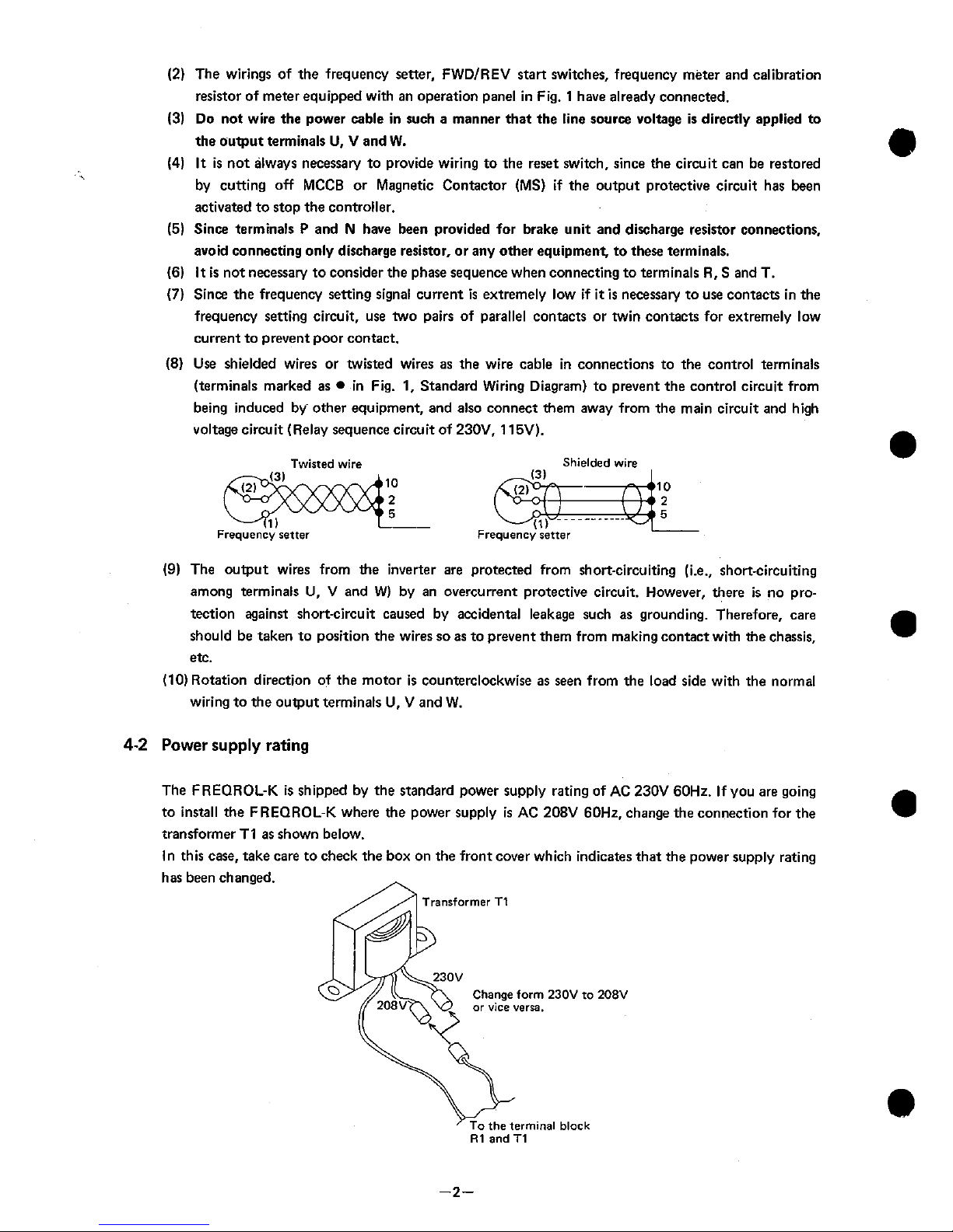
4-2
Power
supply
rating
The FREQROL-K is shipped by the standard power supply rating of
AC
230V 60Hz. If you are going
to install the FREQROL-K where the power supply
is
AC
208V 60Hz, change the connection for the
transformer TI as shown below.
In this case, take care to check the box on the front cover which indicates that the power supply rating
has been changed.
Transformer T1
Change
form
230V
to
208V
or
vice verra.
the terminal black
R1
and
T1
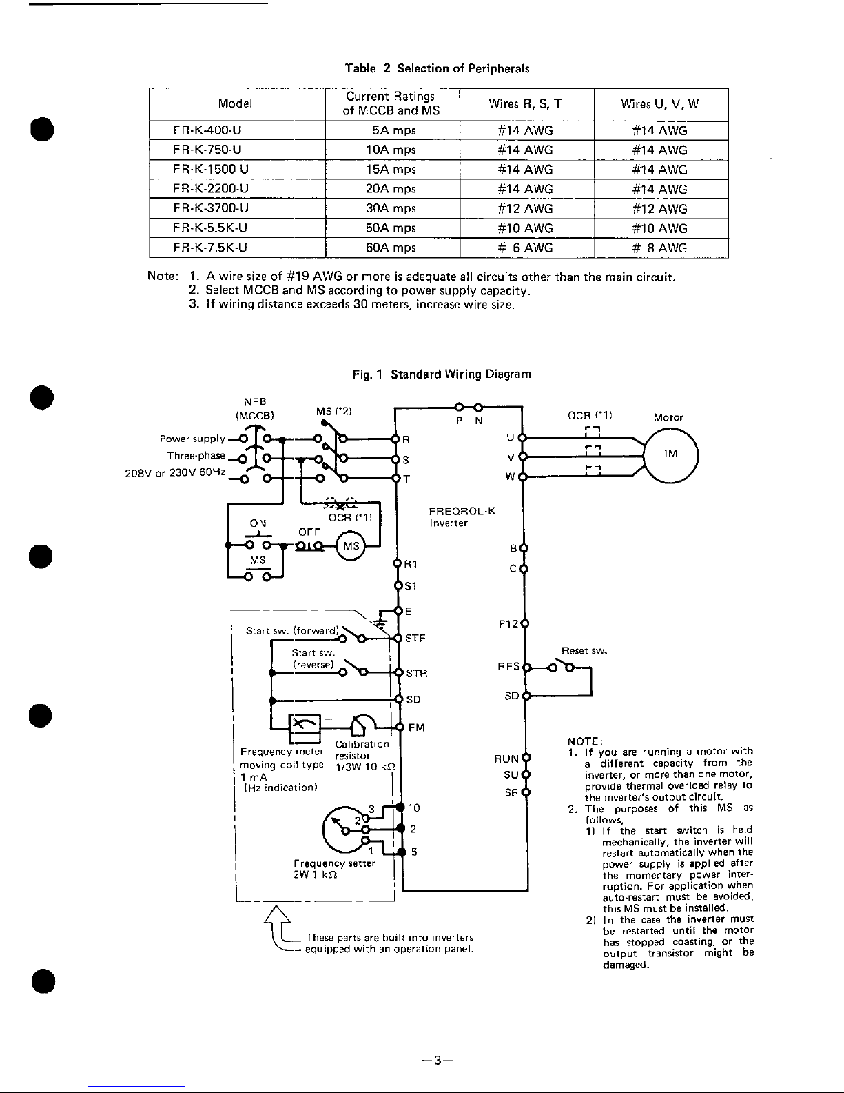
Table 2 Selection of Peripherals
Model
Current Ratings
/
of
MCCR
ad
MS
/
Wires
R,
S.
T
I
Wires
U,
V,
w
I
F
R-K400-U
F
R-K-7504
F
R-K-1500-U
Note:
1. A
wire size of
#19 AWG
or more
is
adequate all circuits other than the main circuit.
2.
Select MCCB and MS according to power supply capacity.
3.
If wiring distance exceeds
30
meters, increase wire size.
FR-K-2200-U
FR-K-3700-U
FR-K-5.5K-U
FR-K-7.5K-U
Fig. 1 Standard Wiring Diagram
5A
mps
10A
mps
15A
m~s
NFB
IMCCBI
MS 1'21
/L
9
20A
mps
30A
mps
50A
mps
60A
mps
Calibratiot
Frequency meter
moving coil type
113~
10
k
1 mA
(Hz indication]
#14 AWG
#I
4 AWG
#14 AWG
Frequency setter
2W
1
kSL
#14 AWG
#14 AWG
#14 AWG
#14 AWG
#I
2
AWG
#lo
AWG
#
6 AWG
-
-
1
OCR ('11 Motor
#14 AWG
#12 AWG
#I0 AWG
#
8
AWG
FREOROL-K
Inverter
I
STF
Reret aw.
STR
SD SD
FM
are
built into inverters
an
operation panel.
NOTE:
1.
If you
are
running a motor with
a
different capacity from the
inverter,
or
more than one motor.
~rovide thermal overload relay to
the inverter's
output circuit.
2. The purpores of this MS
as
follows,
11 If the nsrt switch is held
meCnanlCB
v,
tne
nverter
w
I
restart a.tomat'ca
v
nnon
the
mner
I.OD~Y
I
am
e0
after
..
.
.
.
the momentary power interruption. For application when
auto.restart must be avoided.
this MS must be inrtalled.
21 In the
case
the inverter must
be restarted until the motor
has sopped coasting,
or
the
output transinor might be
damaged.
5.
OPERATIONS
5-1
Points
to
check before operations
After installation and wiring of FREQROL-K
is
completed, check the following points before opera-
ting.
If insulation
is
to be checked with a megger, perform only the test between controller and grounding.
Never perform a megger test between the inverter's terminals.
Also do not perform a megger ten on the control circuit terminals.
Refer to section
6
for details on megger insulation tests.
(1)
Check whether wiring conforms to the standard wiring diagram.
(2) Check for points short-circuited by broken wire, etc.
(3)
Check if any wire is strained.
(4) Check tightness of screws, of terminals and other fasteners.
(5) Check motor load conditions.
5-2
Preparations before
operations
When inspection is completed, open the setting panel flap on the inverter front panel and make the
following setting.
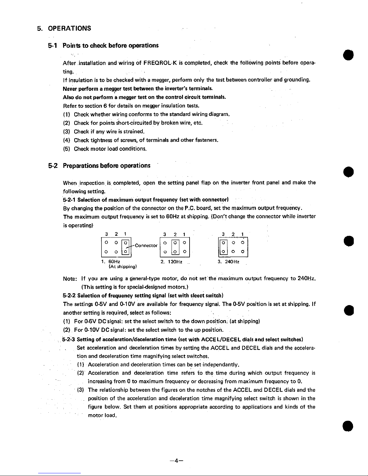
5-2-1
Selection of maximum output frequency (set with connector)
By changing the position of the connector on the P.C. board,
set
the maximum output frequency.
The maximum output frequency
is
set to 60Hz at shipping. (Don't change the connector while inverter
is operating)
1.
60Hz
(At
shipping)
Note: If you are using a general-type motor, do not set the maximum output frequency to 240Hz.
(This setting
is
for specialdesigned motors.)
5-2-2
Selection of frequency setting signal (set with sleect switch)
The settings O-5V and 0-10V are available for frequency signal. The 0-5V position is set at shipping. If
another setting is required, select as follows:
(1) For 0-5V DC signal:
set
the select switch to the down position. (at shipping)
(2) For 0-10V DC signal: set the select switch to the up position.
5-2-3
Setting of
accelerationldeceleration
time (set with ACCE LIDECEL dials and select switches)
Set acceleration and deceleration times by setting the ACCEL and DECEL dials and the acceleration and deceleration time magnifying select switches.
(1) Acceleration and deceleration times can be
set
independantly.
(2)
Acceleration and deceleration time refers to the time during which output frequency
is
increasing from 0 to maximum frequency or decreasing from maximum frequency to 0.
(3)
The relationship between the figures on the notches of the ACCEL and DECEL dials and the
position of the accelerat~on and deceleration time magnifying select switch
is
shown in the
figure below. Set them
at
positions appropriate according to applications and kinds of the
motor load.
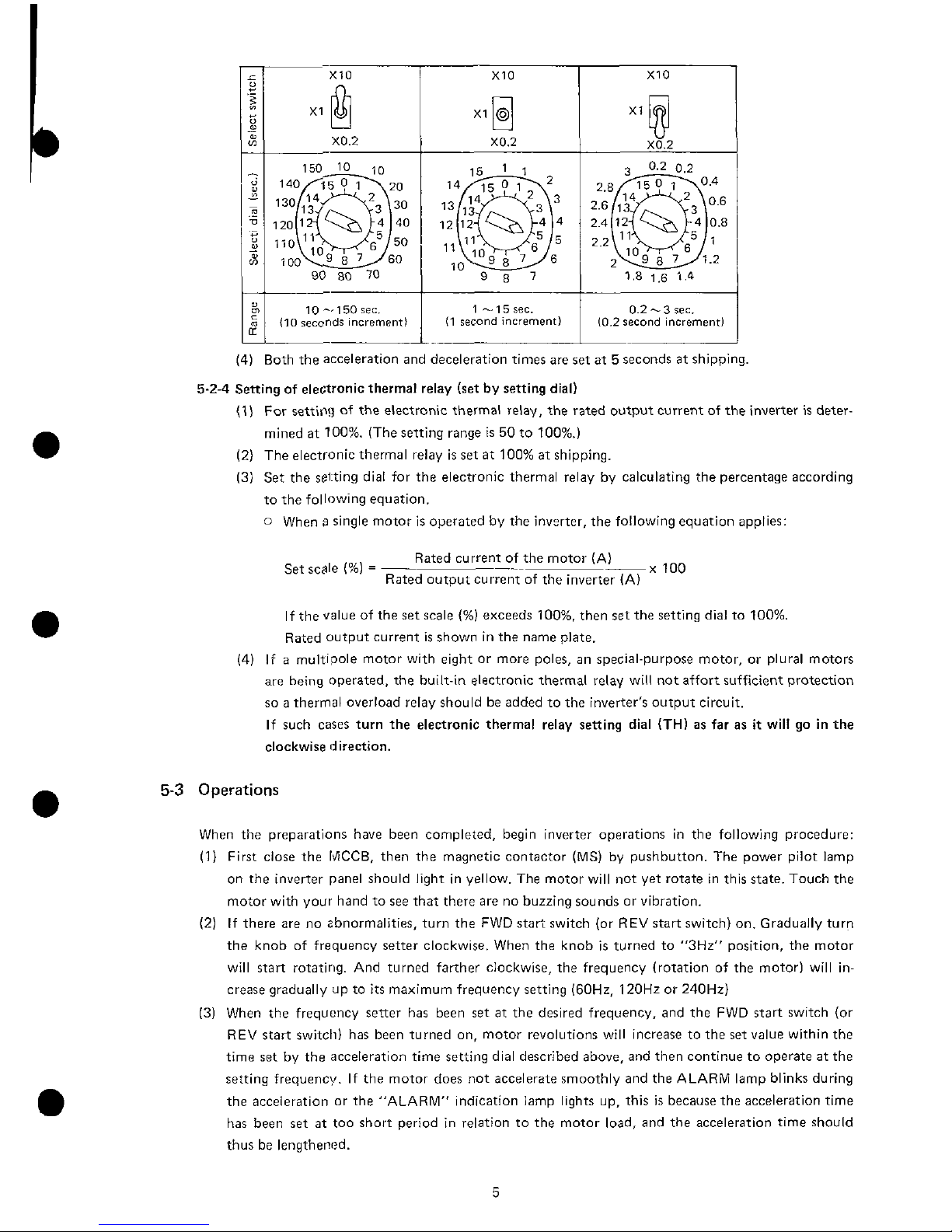
10 -150
rec.
110
secor~ds
increment)
0.2
-3
sec.
10.2
second
increment1
(4) Both the acceleration and deceleration times are set at 5 seconds at shipping.
5-2-4 Sening of electronic thermal relay (set by setting dial)
(1) For setting of the electronic thermal relay, the rated output current of the inverter is deter-
mined at 100%. (The setting range
is
50 to loo%.)
(2) The electronic thermal relay is
set
at 100% at shipping.
(3) Set the setting dial for the electronic thermal relay by calculating the percentage according
to the following equation.
0
When s single motor is operated by the inverter, the following equation applies:
Rated current of the motor (A)
Set scale
(%)
=
-
x
100
Rated output currentof the inverter (A)
If the value of the
set
scale
(%)
exceeds 100%. then
set
the setting dial to 100%.
Rated output current
is
shown in the name plate.
(4)
If a multipole motor with eight or more poles, an special-purpose motor, or plural motors
are
being
operated, the built-in electronic thermal relay will not affort sufficient protection
so a thermal overload relay should be added to the inverter's output circuit.
If such cases turn the electronic thermal relay setting dial
(TH)
as far as
it
will go in the
clockwise direction.
5-3
Operations
When the preparations have been completed, begin inverter operations in the following procedure:
(1) First close the
MCCB,
then the magnetic contactor (MS) by pushbutton. The power pilot lamp
on the inverter panel should light in yellow. The motor will not yet rotate in this state. Touch the
motor with your hand to see that there are no buzzing sounds or vibration.
(2) If there are no zbnormalities, turn the FWD start switch (or REV start switch) on. Gradually turn
the knob of frequency setter clockwise. When the knob is turned to
"3Hz" position, the motor
will start rotating. And turned farther clockwise, the frequency (rotation of the motor) will increase gradually ap to
its
maximum frequency setting (60Hz. 120Hz or 240Hz)
(3) When the frequency setter has been
set
at the desired frequency, and the FWD start switch (or
REV start switch) has been turned on, motor revolutions will increase to the set value within the
time
set
by the acceleration time setting dial described above, and then continue to operate at the
setting frequency. If the motor does not accelerate smoothly and the ALARM lamp blinks during
the acceieration or the "ALARM" indication lamp lights up, this is because the acceleration time
has been
set
at too short period in relation to the motor load, and the acceleration time should
thus be lengthened.
(4) When the FWD start switch (or REV start switch) is turned off while the motor is rotating, motor
speed is decelerated in the time'period set by the DECEL dial. When the frequency falls below
3Hz. the DC dynamic brake will be activated and the motor will stop immediately. If the motor
speed does not decelerate smoothly and the ALARM lamp blinks during the deceleration or the
"ALARM" indication lamp lights up, this is because the deceleration time
is
not sufficient for the
motor load, and the deceleration time should thus be lengthened.
(5) If the FWD start switch and the REV start switch are turned on simultaneously, the motor will not
rotate. Also, if the FWD start switch and the REV start switch are simultaneously activated while
the motor
is
rotating, the motor will begin decelerating in the same manner as when the FWD (or
REV) start switch
is
turned off.
(6) If the FWD start switch is turned off and the REV start switch turned on while the motor is rotat-
ing
forward, the motor speed will decelerate to a frequency of 3Hz. at which point the rotation
direction will automatically be reversed, accelerating gradually tothe frequency that has been set.
The same is also true of movement from reverse to forward rotation.
(7)
If the settings of the acceleration or deceleration times are changed during motor operations, the
previous settings will remain in memory and the changes will not take effect. Note that this
unit
is
designed for changes in the setting of acceleration and deceleration time to be made at a
inverter frequency below 3Hz.
(8) If the protective circuits, such as those against overcurrent and regenerative overvoltage are
activated, the alarm indication lamp will light up in red and the shut-off state will continue. To
reset
after a shut-off, perform the following operations:
0
First turn off the power supply with the MCCB or the Magnetic contactor (MS), then turn
it
on.
0
Short-circuit the terminals between RES (reset) and SD (common) of the control circuit by the
reset switch, then (after about 0.1 second), re-open.
(9)
Use the calibration resistor to adjust the frequency meter so that the frequency
is
indicated as 60,
120 or 240Hz when the commanded voltage (across terminals between 2 and 5)
is
set to 5V DC
or 10V DC by the frequency setting input signal select switch.
Inverters equipped with a frequency meter have already been adjusted at the factory before
shipping.
(10) When the DC dynamic brake activates at below
3Hz during deceleration,
it
may cause a highpitched noise. This noise is common, and does not indicate any abnormalities (The DC dynamic
brake functions for about 0.5 second.)
5.4
Operation's Precautions
When the confirmations described above have been completed you may begin normal operations, but
keep the following points in mind when doing so.
(1)
When a general type motor is being driven by the inverter, the temperature, noise and vibrations
will be somewhat higher than they would be with a commercial power supply.
(2) Since cooling efficiency decreases at low speed operations,
it
is
necessary to reduce the torque
from the rated motor torque. (Refer to the catalog for the torque reduction ratio.)
(3) The FREQROL-K is capable of controlling plural motors at the same time. When the inverter is
used to control more than one motor, care should be taken that the total current requirement for
the simultaneously operated motors
is
within the rated output current of the inverter.
(4) If the FREQROL-K
is
being used to control multipole motors with 8 or more poles, submersible
motors. or other special-purpose motors, carefully examine the rated current and other electrical
specification.
 Loading...