

Mitsubishi FR-K-750-U, FR-K-3700-U, FR-K-1500-U, FR-K-2200-U, FR-K-5.5K-U Instruction Manual
...
MlTSUBlSHl
VVVF TRANSISTOR INVERTER
-INSTRUCTION MANUAL-
(
208/230V
series
I
MlTSUBlSHl
ELECTRIC
FORWORD
Thank you for your purchase of Mitsubishi Multi-Purpose Inverter FREQR0L.K
.
This
is
a variable frequency power supply unit to control the speed of squirrel-cage induction motors . This in-
struction manual is intended both to explain the unit and to outline operation procedures
.
This unit
is
not difficult to operate. but incorrect operation may lead to some troubles. so read this instruction
manual carefully before operation
.
If you use to unit properly. we are sure
it
will give you many years of satisfac-
tion
.
Please make sure to attach this instruction manual to the unit when the unit
is
shipped
.
CONTENTS
1 . UNPACKING 1
2
.
TRANSPORTING 1
.........................................................
3 . INSTALLATION 1
4
.
WIRING AND POWER SUPPLY RATING
........................................
1
............................................................
4-1 Wiring 1
4-2 Power supply rating
...................................................
2
...........................................................
.
5 OPERATIONS 4
..........................................
5-1 Points to check before operations 4
5-2 Preparations before operations
............................................
4
.........................................................
5-3 Operations 5
.................................................
5-4 Operation's precautions
6
6
.
MAINTENANCE AND INSPECTION
............................................
7
7 . CONSTRUCTION AND ARRANGEMENTOF CONTROLLER PARTS
.....................
8
8
.
TROUBLESHOOTING AND COUNTERMEASURE
..................................
9
8-1 Troubleshooting chart
..................................................
9
8-2
Failures indicated by lighting of alarm indication lamps and how to deal with them
.........
13
.............................................
8-3 Measuring voltage and current
15
9
.
STANDARDSPECIFICATIONS
...............................................
17
10.
PROTECTIVEFUNCTIONS
..................................................
18
.
11 INPUT/OUTPUTTERMINAL
.................................................
19

1.
UNPACKING
After unpacking your FREQROL-K, first check the following points.
0
Refer to the name plate to confirm that the model and the output rating is indeed the one you ordered.
(See table
1)
0
Check where there has been any damage or breakage to the FREQROL-K during transportation.
If you have any doubts about the above, or find any damage to the unit, please contact your local service
representative.
Table
1
FR-K Series Configuration
Motor output (HP) 112
1
2
3
5
7.5 10
Without operation
FR-K-
FR-K- FR-K-
FR-K- FR-K- FR-K- FR-K-
panel 400-U 750-U 1500-U 2200-U 3700-U
5.5K-U 7.5K-U
With operation FR-K-
FR-K- FR-K-
FR-K- FR-K-
FR-K- FR-K-
panel 400M-U 750M-U
1500M-U 2200M-U
3700M-U 5.5KM-U 7.5KM-U
Note: The operation panel is provided with a frequency setter, a frequency meter and a FWDIREV starting
switch.
2.
TRANSPORTING
When transporting the FREQROL-K, handle
it
gently to prevent damage. There are depressions on both the
top and the bottom where the unit can be grasped, and these should be held when
it
is moved.
Do not apply too much force to the fan at the bottom of the unit. The unit is covered with a plastic case,
and care should be taken not to apply force only to this cover during transport.
a
3.
INSTALLATION
o
Place the inverter in a clean and well ventilated location. Avoid locations exposed to direct sunlight, or
subject to high temperatures, humidity, dust or corrosive gases.
0
Install the inverter securely on the wall with volts or screws, vertically so that the letters "FREQROL-K"
appears front.
0
Since the inverter does generate some heat during operations, any other equipment or parts should be
installed at least 10 cm away from up and the bottom to prevent heat confined.
The brake resistor attached to the rear of the unit also generates heat, so the unit should not be placed on
a wall with low heat resistance.
0
If your inverter is one equipped with an operation panel, take care to put
it
in a place where
it
can be
easily operated.
4.
WIRING AND POWER SUPPLY RATING
4-1
Wiring
Connect wiring correctly according to following instructions and refer to Fig. 1, Standard Wiring
Diagram.
Fow wiring of the peripheral devices such as MCCB, refer to Table
2,
Selection of Peripherals.
(1)
When the wiring cover located at the bottom of the inverter
is
pushed inward and then pulled
toward the operator, the wiring cover alone
is
removed thus exposing all terminal blocks. A
corrugated gripping surface has been provided for your convenience. Now perform wiring.
(2)
The wirings of the frequency setter, FWDIREV start switches, frequency meter and calibration
resistor of meter equipped with an operation panel in Fig. 1 have already connected.
(3) Do not wire the power cable in such a manner that the line source voltage is directly applied to
the output terminals
U,
V
and
W.
(4)
It
is
not always necessav to provide wiring to the reset switch, since the circuit can be restored
by cutting off
MCCB
or Magnetic Contactor (MS) if the output protective circuit has been
activated to stop the controller.
(5)
Since terminals P and N have been provided for brake unit and discharge resistor connections,
avoid connecting only discharge resistor, or any other equipment, to these terminals.
(6)
It
is not necessary to consider the phase sequence when connecting to terminals R, S and T.
(7)
Since the frequency setting signal current
is
extremely low
if
it
is necessary to use contacts in the
frequency setting circuit, use two pairs of parallel contacts or twin contacts for extremely low
current to prevent poor contact.
(8)
Use
shielded wires or twisted wires as the wire cable in connections to the control terminals
(terminals marked as
in Fig. 1, Standard Wiring Diagram) to prevent the control circuit from
being induced by other equipment, and also connect them away from the main circuit and high
voltage circuit (Relay sequence circuit of
230V. 115V).
Twisted wire
.~.
Shielded wire
Frequency setter Frequency setter
(9)
The output wires from the inverter are protected from short-circuiting (i.e., short-circuiting
among terminals
U,
V and W) by an overcurrent protective circuit. However, there is no protection against shortcircuit caused by accidental leakage such as grounding. Therefore, care
should be taken to position the wires so as to prevent them from making contact with the chassis,
etc.
(10) Rotation direction of the motor is counterclockwise as seen from the load side with the normal
wiring to the output terminals
U,
V and W.
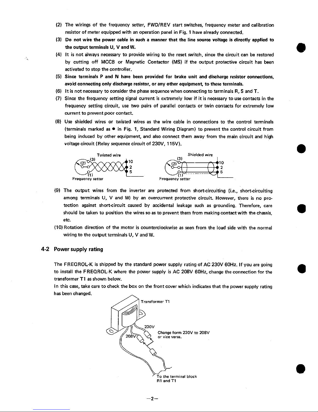
4-2
Power
supply
rating
The FREQROL-K is shipped by the standard power supply rating of
AC
230V 60Hz. If you are going
to install the FREQROL-K where the power supply
is
AC
208V 60Hz, change the connection for the
transformer TI as shown below.
In this case, take care to check the box on the front cover which indicates that the power supply rating
has been changed.
Transformer T1
Change
form
230V
to
208V
or
vice verra.
the terminal black
R1
and
T1
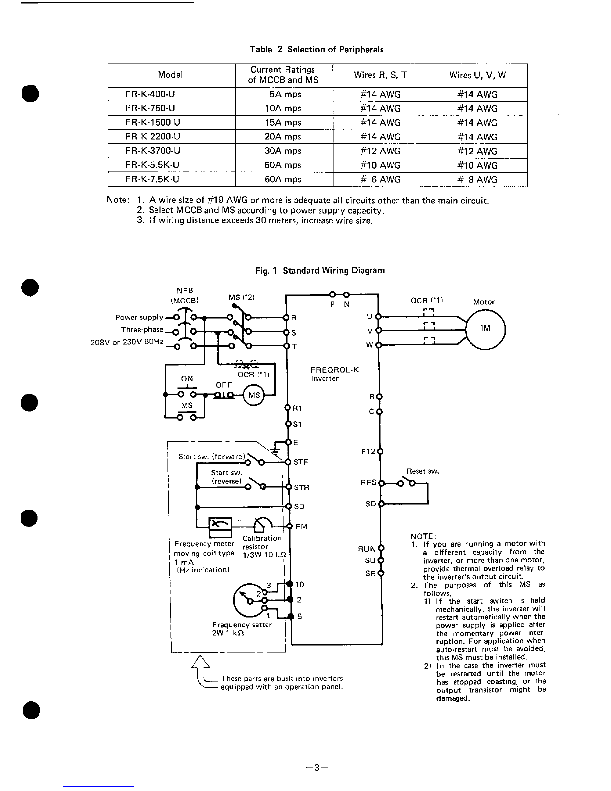
Table 2 Selection of Peripherals
Model
Current Ratings
/
of
MCCR
ad
MS
/
Wires
R,
S.
T
I
Wires
U,
V,
w
I
F
R-K400-U
F
R-K-7504
F
R-K-1500-U
Note:
1. A
wire size of
#19 AWG
or more
is
adequate all circuits other than the main circuit.
2.
Select MCCB and MS according to power supply capacity.
3.
If wiring distance exceeds
30
meters, increase wire size.
FR-K-2200-U
FR-K-3700-U
FR-K-5.5K-U
FR-K-7.5K-U
Fig. 1 Standard Wiring Diagram
5A
mps
10A
mps
15A
m~s
NFB
IMCCBI
MS 1'21
/L
9
20A
mps
30A
mps
50A
mps
60A
mps
Calibratiot
Frequency meter
moving coil type
113~
10
k
1 mA
(Hz indication]
#14 AWG
#I
4 AWG
#14 AWG
Frequency setter
2W
1
kSL
#14 AWG
#14 AWG
#14 AWG
#14 AWG
#I
2
AWG
#lo
AWG
#
6 AWG
-
-
1
OCR ('11 Motor
#14 AWG
#12 AWG
#I0 AWG
#
8
AWG
FREOROL-K
Inverter
I
STF
Reret aw.
STR
SD SD
FM
are
built into inverters
an
operation panel.
NOTE:
1.
If you
are
running a motor with
a
different capacity from the
inverter,
or
more than one motor.
~rovide thermal overload relay to
the inverter's
output circuit.
2. The purpores of this MS
as
follows,
11 If the nsrt switch is held
meCnanlCB
v,
tne
nverter
w
I
restart a.tomat'ca
v
nnon
the
mner
I.OD~Y
I
am
e0
after
..
.
.
.
the momentary power interruption. For application when
auto.restart must be avoided.
this MS must be inrtalled.
21 In the
case
the inverter must
be restarted until the motor
has sopped coasting,
or
the
output transinor might be
damaged.
5.
OPERATIONS
5-1
Points
to
check before operations
After installation and wiring of FREQROL-K
is
completed, check the following points before opera-
ting.
If insulation
is
to be checked with a megger, perform only the test between controller and grounding.
Never perform a megger test between the inverter's terminals.
Also do not perform a megger ten on the control circuit terminals.
Refer to section
6
for details on megger insulation tests.
(1)
Check whether wiring conforms to the standard wiring diagram.
(2) Check for points short-circuited by broken wire, etc.
(3)
Check if any wire is strained.
(4) Check tightness of screws, of terminals and other fasteners.
(5) Check motor load conditions.
5-2
Preparations before
operations
When inspection is completed, open the setting panel flap on the inverter front panel and make the
following setting.
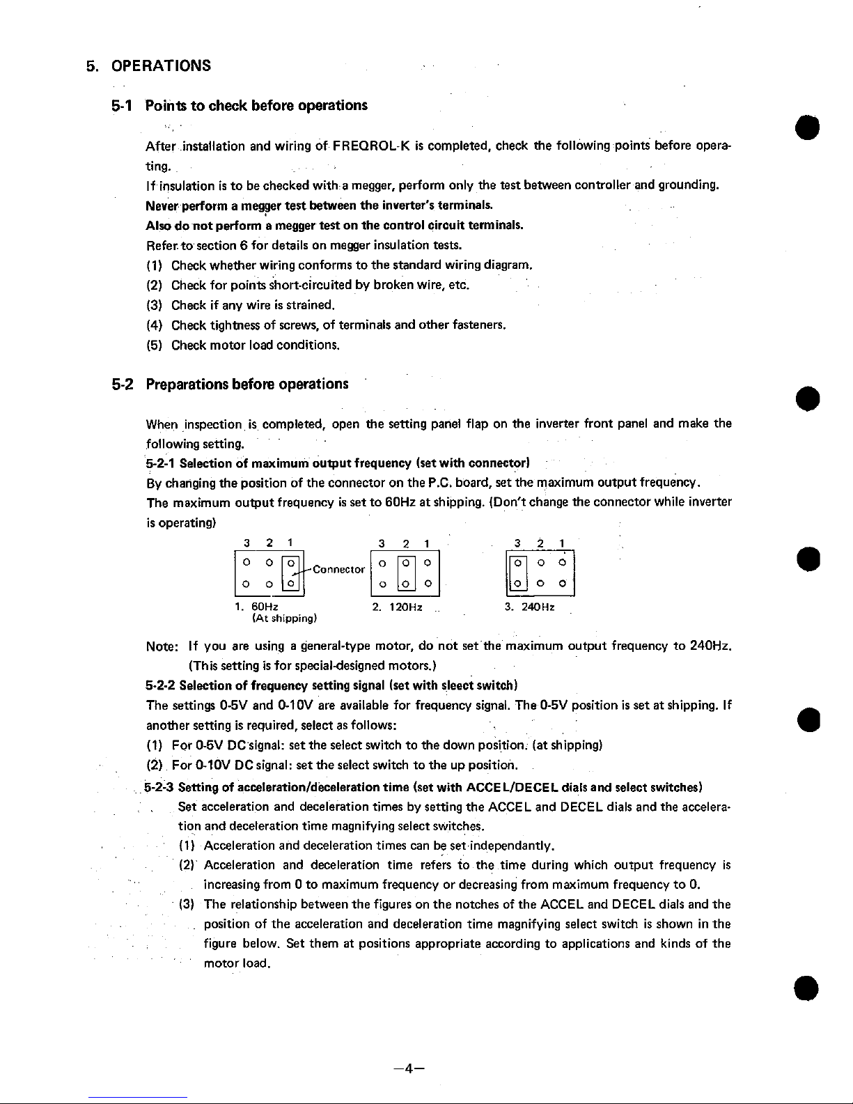
5-2-1
Selection of maximum output frequency (set with connector)
By changing the position of the connector on the P.C. board,
set
the maximum output frequency.
The maximum output frequency
is
set to 60Hz at shipping. (Don't change the connector while inverter
is operating)
1.
60Hz
(At
shipping)
Note: If you are using a general-type motor, do not set the maximum output frequency to 240Hz.
(This setting
is
for specialdesigned motors.)
5-2-2
Selection of frequency setting signal (set with sleect switch)
The settings O-5V and 0-10V are available for frequency signal. The 0-5V position is set at shipping. If
another setting is required, select as follows:
(1) For 0-5V DC signal:
set
the select switch to the down position. (at shipping)
(2) For 0-10V DC signal: set the select switch to the up position.
5-2-3
Setting of
accelerationldeceleration
time (set with ACCE LIDECEL dials and select switches)
Set acceleration and deceleration times by setting the ACCEL and DECEL dials and the acceleration and deceleration time magnifying select switches.
(1) Acceleration and deceleration times can be
set
independantly.
(2)
Acceleration and deceleration time refers to the time during which output frequency
is
increasing from 0 to maximum frequency or decreasing from maximum frequency to 0.
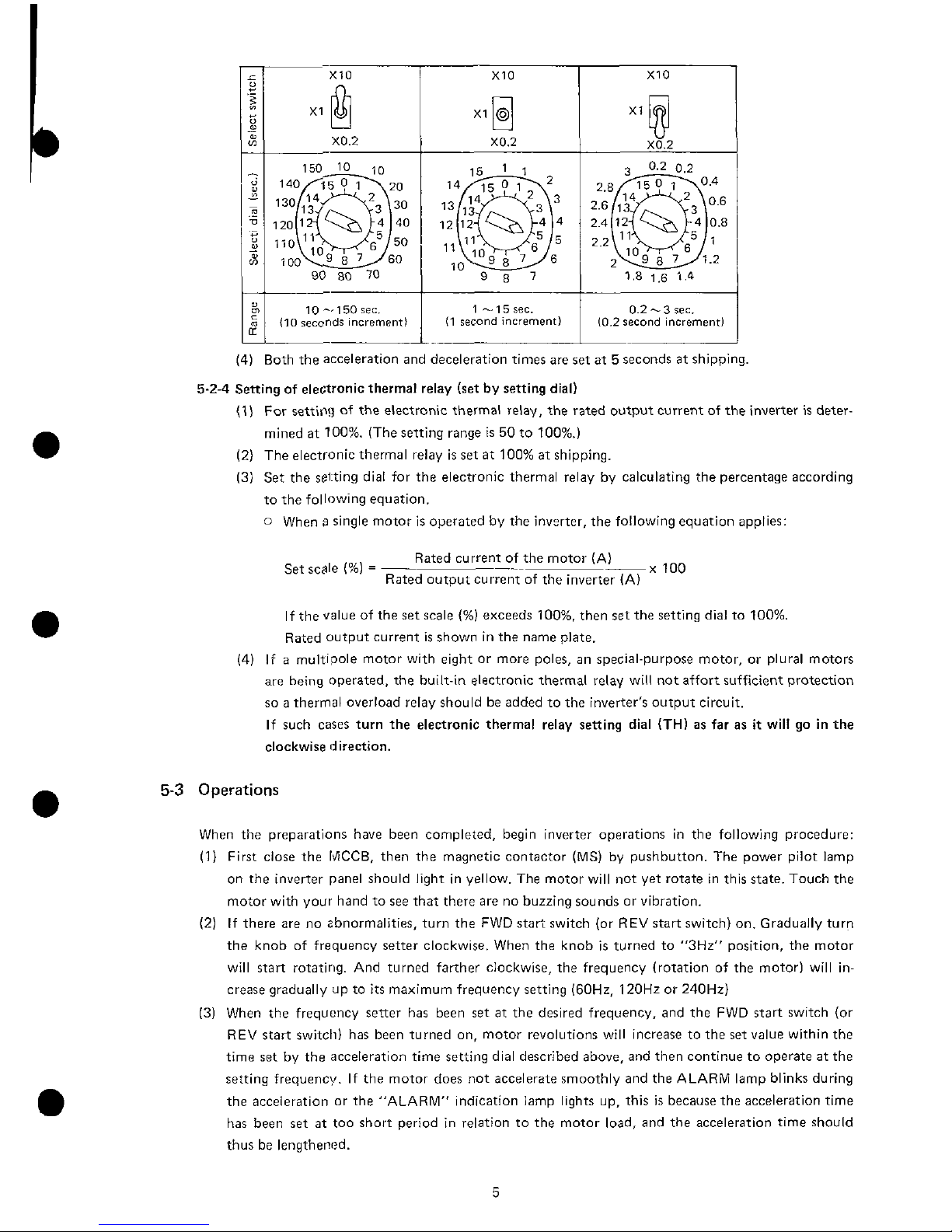
(3)
The relationship between the figures on the notches of the ACCEL and DECEL dials and the
position of the accelerat~on and deceleration time magnifying select switch
is
shown in the
figure below. Set them
at
positions appropriate according to applications and kinds of the
motor load.
10 -150
rec.
110
secor~ds
increment)
0.2
-3
sec.
10.2
second
increment1
(4) Both the acceleration and deceleration times are set at 5 seconds at shipping.
5-2-4 Sening of electronic thermal relay (set by setting dial)
(1) For setting of the electronic thermal relay, the rated output current of the inverter is deter-
mined at 100%. (The setting range
is
50 to loo%.)
(2) The electronic thermal relay is
set
at 100% at shipping.
(3) Set the setting dial for the electronic thermal relay by calculating the percentage according
to the following equation.
0
When s single motor is operated by the inverter, the following equation applies:
Rated current of the motor (A)
Set scale
(%)
=
-
x
100
Rated output currentof the inverter (A)
If the value of the
set
scale
(%)
exceeds 100%. then
set
the setting dial to 100%.
Rated output current
is
shown in the name plate.
(4)
If a multipole motor with eight or more poles, an special-purpose motor, or plural motors
are
being
operated, the built-in electronic thermal relay will not affort sufficient protection
so a thermal overload relay should be added to the inverter's output circuit.
If such cases turn the electronic thermal relay setting dial
(TH)
as far as
it
will go in the
clockwise direction.
5-3
Operations
When the preparations have been completed, begin inverter operations in the following procedure:
(1) First close the
MCCB,
then the magnetic contactor (MS) by pushbutton. The power pilot lamp
on the inverter panel should light in yellow. The motor will not yet rotate in this state. Touch the
motor with your hand to see that there are no buzzing sounds or vibration.
(2) If there are no zbnormalities, turn the FWD start switch (or REV start switch) on. Gradually turn
the knob of frequency setter clockwise. When the knob is turned to
"3Hz" position, the motor
will start rotating. And turned farther clockwise, the frequency (rotation of the motor) will increase gradually ap to
its
maximum frequency setting (60Hz. 120Hz or 240Hz)
(3) When the frequency setter has been
set
at the desired frequency, and the FWD start switch (or
REV start switch) has been turned on, motor revolutions will increase to the set value within the
time
set
by the acceleration time setting dial described above, and then continue to operate at the
setting frequency. If the motor does not accelerate smoothly and the ALARM lamp blinks during
the acceieration or the "ALARM" indication lamp lights up, this is because the acceleration time
has been
set
at too short period in relation to the motor load, and the acceleration time should
thus be lengthened.
(4) When the FWD start switch (or REV start switch) is turned off while the motor is rotating, motor
speed is decelerated in the time'period set by the DECEL dial. When the frequency falls below
3Hz. the DC dynamic brake will be activated and the motor will stop immediately. If the motor
speed does not decelerate smoothly and the ALARM lamp blinks during the deceleration or the
"ALARM" indication lamp lights up, this is because the deceleration time
is
not sufficient for the
motor load, and the deceleration time should thus be lengthened.
(5) If the FWD start switch and the REV start switch are turned on simultaneously, the motor will not
rotate. Also, if the FWD start switch and the REV start switch are simultaneously activated while
the motor
is
rotating, the motor will begin decelerating in the same manner as when the FWD (or
REV) start switch
is
turned off.
(6) If the FWD start switch is turned off and the REV start switch turned on while the motor is rotat-
ing
forward, the motor speed will decelerate to a frequency of 3Hz. at which point the rotation
direction will automatically be reversed, accelerating gradually tothe frequency that has been set.
The same is also true of movement from reverse to forward rotation.
(7)
If the settings of the acceleration or deceleration times are changed during motor operations, the
previous settings will remain in memory and the changes will not take effect. Note that this
unit
is
designed for changes in the setting of acceleration and deceleration time to be made at a
inverter frequency below 3Hz.
(8) If the protective circuits, such as those against overcurrent and regenerative overvoltage are
activated, the alarm indication lamp will light up in red and the shut-off state will continue. To
reset
after a shut-off, perform the following operations:
0
First turn off the power supply with the MCCB or the Magnetic contactor (MS), then turn
it
on.
0
Short-circuit the terminals between RES (reset) and SD (common) of the control circuit by the
reset switch, then (after about 0.1 second), re-open.
(9)
Use the calibration resistor to adjust the frequency meter so that the frequency
is
indicated as 60,
120 or 240Hz when the commanded voltage (across terminals between 2 and 5)
is
set to 5V DC
or 10V DC by the frequency setting input signal select switch.
Inverters equipped with a frequency meter have already been adjusted at the factory before
shipping.
(10) When the DC dynamic brake activates at below
3Hz during deceleration,
it
may cause a highpitched noise. This noise is common, and does not indicate any abnormalities (The DC dynamic
brake functions for about 0.5 second.)
5.4
Operation's Precautions
When the confirmations described above have been completed you may begin normal operations, but
keep the following points in mind when doing so.
(1)
When a general type motor is being driven by the inverter, the temperature, noise and vibrations
will be somewhat higher than they would be with a commercial power supply.
(2) Since cooling efficiency decreases at low speed operations,
it
is
necessary to reduce the torque
from the rated motor torque. (Refer to the catalog for the torque reduction ratio.)
(3) The FREQROL-K is capable of controlling plural motors at the same time. When the inverter is
used to control more than one motor, care should be taken that the total current requirement for
the simultaneously operated motors
is
within the rated output current of the inverter.
(4) If the FREQROL-K
is
being used to control multipole motors with 8 or more poles, submersible
motors. or other special-purpose motors, carefully examine the rated current and other electrical
specification.

(5)
Do not add a capacitor nor surge absorber to the output circuit of the inverter. This may activate
the overcurrent protection.
(6)
If you are using a motor with mechanical brakes, the brake exciting circuit should not be connected to the inverter output, and make certain theat brake action can be affected after turning
off the inverter's power supply.
(7)
If using motors of different capacity or special-purpose motors, or if more than one motor is being
used simultaneously, add
a
thermal overload relay to the inverter output circuit to protect the
motor from being burned up. In this case turn the electronic thermal relay setting dial (TH) on
the operation panel as far as
it
will go in the clockwise direction.
(8)
Th= FR-K-400 can also be used with a single phase power supply, but when doing so be sure to
connect the power supply to terminals R and
S.
(9)
Since the built-in brake resistor will cause temperature increases, mount
it
on noninflammable
materials such as metal or concrete.
6.
MAINTENANCE AND INSPECTION
The FREQROL-K is the static type, so almost no daily maintenance is required. The following maintenance
practices should, however, be observed.
(1)
Since the capacitor in the inverter remains charged at high voltage for a while after the inverter is turned
off, perform inspections only after charge indication lamp "CHARGE" goes out. Also, the cooling fan
will continue to run for some time after the power has been turned off, so be careful to keep hands away
from this area.
(2)
From time to time, inspect the inverter for dust and dirt accumulated inside, and clean
it
if there is a
buildup.
(3)
Check the tightness of terminal block screws and mounting screws. If they come any loose, tighten
them securely. Make certain there are no defects in the wiring parts or components. Replace defective
wiring part if found, or contact your service representative.
(4) Megger test
a)
When performing a megger test on the external equipment, remove all inverter terminals so that the
test voltage will not be applied to the inverter.
b)
Perform megger tests only for the main circuit of the inverter as shown in Fig.
2.
Do not apply the
test voltage to the control circuit.
c)
TO check the FFiEQROL-K control circuit, use a multimeter (set to high resistance range position).
Do not use a megger or buzzer.
Fig.
2
Megger Test
-
Earth
terminal

7.
CONSTRUCTION AND ARRANGEMENT OF INVERTER PARTS
I
As noted above, wiring requires only the removal of the wiring cover at the bottom of the inverter. To
inspect the inverter's interior, however, proceed as follows:
(1)
When the wiring cover
is
removed, the plastic cover's two set screws will be exposed. Remove these
screws and slide the plastic cover upward.
(2)
The
P.C.
board of the control circuit has been attached by set screws (for inverters below class FR-K-
3700-U) or the board support (for FR-K-5.5K-U and FR-K-7.5K-U).
Fig.
3
Type
FR-K-400-U
to
FR-K-3700-U
Fig.
4
Type
FR-K-5.5K-U and FR-K-7.5K-U
Control circuit terminal arrangement
TR?
Control circuit terminal arrangement
TB4

8.
TROUBLESHOOTING AND COUNTERMEASURE
In the unlikely event that there should,be problems with the inverter or
its
should lose any of its functions,
use the troubleshooting chart below to identify the cause and apply the appropriate countermeasure.
If
your
problem
is
not described below, the inverter
is
out of order, one of the parts has been damaged or if you have
any other problem not dealt with here, contact with your local service representation.
8-1
Troubleshooting Chart
(1)
Motor does not run
START
ii
Note
1.
power supply has been
Are MCCB (ELB), MS.
Yes
terminals R and S, S
etc. turned
on?
Defective MCCB (ELBI
or
and
T.T and
S.
MS,
or
wiring trouble
lamp lit
up?
pacity transformer?
Inverter trouble
Cooling fan trouble
tion relay of radiation
Ventilation obstruction fan. Remove
Set reret rwitch lbetween terminals
Is reset switch "ON"? RES and SD) to
"OFF"
1s
voltage
across
termi-
t
yes
.(
Defective
reret
switch
nals RES
and
SD below
Transistor falls to function when energized.
14V?
L
No
lcont'd
on
next right page1

(cont'd from left pagel
I
No
I
Are
terminals STF and
Either STF or STR should
be
STR both ON?
continuity; not both.
J,
No
1s
voltage across termi-
nals STF lor STRI and
Poor start switch contact
SD greater than
1V7
,
Transistor fsilr to function when energized.
Has voltage been applied
P
to motor terminals
U
Has voltage been applied Yes
and V, V and
W,
and
W
>
to frequency command
Inverter trouble
,and
U?
J
terminals 2and 5?
I
v
Is
voltage across termi-
%,-
I
nalr 5 and
10
5V (or
trouble or wiring
trouble
Motor overload
Motor trouble
Magnetic brake does not open.
.
Motor trouble
Note
0:
ELL3 = Earth Leakage
Braker
Wiring trouble
Note 1: Out of voltage should
be
within
f
10%
of rated voltage.
Note
2:
Is
thermal overload relay IOCRI connected.
Note
3:
Imbalanced should be within
1%
of maximum output voltage.
Note
3.
Is
three-phase voltage
out of balance?
I
Yes
>
Is voltage still unbalan-
ced after disconnecting Inverter trouble
motor terminals.

(2)
Motor buzzes and does not run.
Note
4.
A
Does
frequency meter fail
to change
even
though
frequency setter has been
turned to increase?
Is output voltage
across
terminals U and
V. V
and W,
and
W and
U
Inverter trouble
out
of
balance?
Overload
causer
activation
Increase inverter capacity
of protection againat stalls.
and motor capacity.
Motor
trouble
Note
4:
Examine this with motor disconnected
(3)
Motor runs
at
constant speed and cannot be controlled.
/-,
OV
to
5~ lor
from
1~
to
Frequency
rener
trouble
10Vl
across
terminals
2
and
5
even
after
freque-
ncy setter has been tur-
ned
on?
No
Inverter trouble
(4)
Motor overheats.
u
Ir motor overloaded?
Yes
Lighten the load
or
increase capacity of motor and
No
Does
motor
run
at
low
speeds for long periods
Lighten the load
or
ventilate the motor from
of time?
or
increasecapacity of motor
and
inverter.
&
Note.
6
I
I
IS
output voltage among
terminals
U
and
V,
V
and W, Wand U out Of
Inverter trouble
balance?
Is
there any obstruction
to
motor cooling? Remove obstruction.
Inverter trouble
Note
5:
Overload should
be
below
110%
of motor rated current
l60Hz. 220V
ACI.
Note
6:
Proper balance
is
not more
1%
of maximum output voltage.

(5)
Motor
does
not
run
smoothly
Note
7.
Does problem occur Is accelerationldecele- ngthen acceleration1
during acceleration/ ration time
too
short?
deceleration time.
deceleration?
I
Does output voltage
fluctuctuate?
Load
4
too heavy.
Increase capacity of
motor and inverter.
\L
Is voltage out of balance
amaung terminals
U
and
yes
V,
V
and
W.
W
and
U?
NO
Har there been
a
load Yes
Minimize load variation
or
attach flywheel to motor.
vibration?
Run
with load vaciation.
Is there any backlash in
chain, gear. etc.?
Improve mechanical parts.
No
Capacitor
for
constant
Has inverter been
used
output voltage has been
for
5t0
10
years?
used beyond service life.
Inverter trouble
Note
7:
Anivatlon
of
protectton function against stalls causes unstable
acceleratianldeceleratian

8-2
Failures Indicated
by
Lighting of Alarm Indication Lamps and How to Deal with Them
The protective functions can be activated by various conditions, as shown below. If an alarm indication
lamp lights up,
it
is
important to keep your head and examine the cause of the problem, and then to
apply the appropriate countermeasure.
Alarm
Uarm
ndication
amp "ON'
Cause
Acceleration time
is
too
short.
Inverter's output circuit
is
turned on and off.
Peak load reached
nstan-ianeously.
Load
is
too heavy
Built-in brake is being
lsed too frequently.
-.
:Ither a capacitor for
lower factor improvement
lr a capacitor for surge
jbsorber has been inserted
3t
inverter's output circuit.
jhort-circuit or ground
'ault in the output circuit
)f the inverter.
Motor
is
turned on again
luring free running (runnin
sf
inertia force after power
ias been turned off).
Description
Check whether the magneti
contactor has been turned
on after the inverter start
signal (ST) went ON.
Even after acceleration timt
has been lengthened, motor
hardly runs before the alarn
indication lamp lights up.
(The electronic thermal
relay has been activated dut
to overload or overheating
caused by low speed operations, thus turning alarm
indication lamp on.)
Deceleration may be done
in several stages. If the
maximum number
all~wabl~
is exceeded, however, this
will increase the frequency
of use of the brake, and an
alarm indication lamp will
come on.
There is an overcurrent
because impedence of
capacitor is small against
high frequency.
Ground faults do not alway
cause an overcurrent trip
(OCT) state. If a ground
fault occurs, it may lead to
inverter trouble.
Since inverter starts operation at
3H2,
motor runs by
regenerative operation,
which generates overcurreni
Countermeasure
Lengthen acceleration1
deceleration time.
Correct sequence if wrong.
If
it
is
necessary to turn on
and off of inverter's output
circuit, increase the capacit
of inverter by five times or
more.
Adjust machine so that
peak load
is
not reached.
Increase capacity of in-
verter by
1
or 2 class.
Since static friction torque
is
larger than the torque of
motors under
3Hz
at startup, increase capacity of
motor and inverter. Lighter
the load or change operations partern.
Either lengthen the deceleration time or lessen its
frequency. Add an external brake unit.
Remove them. If they
have been factory-set, care
should be taken not to
forget to remove them.
It
is recommended to
insert a reactor into the
input circuit in order to
improve the power factor.
Locate the short-circuited
points and apply the appropriate countermeasure.
Restart the motor only
after
it
has stopped completely.
In automatic operation, use
a timer to start the motor
after
it
has stopped completely.

Alarm
Alarm
indication
lamp "ON"
Cause
I
Description
Activation of the
temperature detection
relay of the rediation fin.
External noise.
When the fin for cooling
power modules
is
overheated, the temperature
sensor activates to stop
output
Consider the possibility
of external noise when
the alarm indication lamp
lights up for causes other
than these described above.
t
Countermeasure
Instantaneous power
failure.
Cooling fan trouble or
ventilation obstruction in
radiation fin has caused a
rise
in temperature, so
remove those troubles.
Twisted wire or shield
wire are used fo the frequency setting signal circuit
(10,
2.5).
Shield wire
should be connected to
terminal
"5
only and do
not connect shield wire
with grounding or around
terminal of other circuit
(i.e., instrumentation
circuit).
Reset the inverter and
restart
it.
If you wish to
keep the alarm state on
display, use an external
circuit.
If there has been an in
stantaneous power failure
for
15
msec or more, and
the power supply has been
restored before the motor
has stopped after a free
running, overcurrent may
occur.
Note: If you cannot identify the trouble even after checking all the points listed above, try discon-
necting the motor from the inverter. If the alarm indication lamp still comes on, there has been
a breakdown in the inverter.

8-3
Measuring Voltage
and
Current
Since the primary and secondary voltage and current contain high frequency, data may differ depending upon the instrument used and the circuit to be measured.
If you use
a
measuring instrument for commercial frequency, select one listed in Table 3 and measure
the circuit as shown in Fig.
5
Variation of the indicated value are shown in Fig.
6.
However, even measuring instruments of the same
accuracy may be inconsistent because of differences in factors such as manufacturer, model type or
year made, etc.
FR-K
Inverter
7
Fig. 5 Points to be Measured and Examples of Measuring Instruments
Example: Output voltage
of
inverter
Motor rating:
3.7
kW
4P
FR-K.3700-U
Inverter
Take
the indicated
value
of
rectifier type voltmeter
as
100%.
4
Rectifier type
k
Moving-iron type
Electrothermic type
Fig. 6 Variation of Indicated Value Depending on the Type of the
Measuring Instrument

Table 3 Terminals to be Measured and Measuring Instrument
Item
Supply voltage: V1
Current at power supply:
I1
Terminals to be measured
Across terminals R and S,
Sand T, and T and R.
Line current at terminals
R, S and T.
Terminals R, Sand T and
across terminals R and S,
and S and T.
Power at power supply:
P1
Power factor at power
supply: Pfl
Measuring instrument
Moving-iron type
9:
fi
Moving-iron type
Electro-dynamo-
meter type
Measure supply voltage (Vl), current at power supply (11) and power at powet
supply (PI
),
and calculate power factor using equation shown below:
Remarks (reference value)
Commercial voltage:
230V
P
=
WII
+
Wn
Voltage at output: V2
Pfl
=
PI
fiV1
.
I1
100%
Difference between each
Across terminals
U
and V,
V and W, and Wand
U.
phase should be within
10%
Rectifier type
+
(Moving-iron type
is
not available)
Current at output: 12
Below rated current of
inverter
Difference between each
phase should be within
10%.
Line current at terminals
U,
V and W.
Power at output: P2
Moving-iron type
Terminals
U,
V and W and
Electro-dynamo-
across terminals
U
and V,
$
meter type
and V and W.
Power factor at output:
Pf2
Calculate in a similar manner as for power supply, using the following equation:
Output of converter Across terminals P and
N
Moving-coil type
(such as multi-
meter)
Charge lamp lights up
when voltage is
10V DC
or more.
1.35 x v1
Maximum 380V DC
during regeneration.
0 to 5V DC
I
3
Movinwcoil tvpe
Frequency setting signal Across terminals 2 and
5
(such
is
multi-.
W
meter)
(internal resistance
5 0 kCl or more)
Power supply for frequency setting
Across terminals 10 and 5
Across terminals FM and
SD
About 5 V DC at
maximum
frequenq
(when frequency
meter is connected.)
Open: 13V DC to
19V DC
ON voltage:
1
V
DC or
less
OFF voltage:
13V DC or more
Power supply fot
frequency
Forward operation signal Across terminals STD and
SD
Reverse operation signal
Across terminals STR and
SD
Reset Across terminals RES and
SD
Base shut-off (alarm)
signal
Across terminals Band C
Moving-coil type
(such as multimeter)
Measuring continuity
Continuity when power
supply is shut off or
during normal operations.

9.
STANDARD SPECIFICATIONS
FR-K- FR-K- FR-K- FR-K- FR-K- FR-K- FR-K400-U
/
750-U 1500-U 2200-U
2.700-U
/
55K-U
7.5K.U
I
Nominal output (HP)
-
Output capacity (kVA)
-
Rated output current (A)
Maximum output voltage
Power source requirement (kVA)
ilVeight (kg)
Construction Totally enclosed type
1
Enclosed type
Voltagelfrequency
Allowable voltage regulation
Allowable frequency regulation
Control method Sinusoidal PWM,
Voltage-control
Frequency range
1
:
10
(6 - 60Hr) or
1 : 20 (6 - 120Hz) or 1 : 40 (6 - 240Hz) selectable
(Operation starts at 3Hz)
Frequency resolution
(Hzlmaximum frequency)
Frequency accuracy
Voltageifrequency ratio
VoltagefFrequency ratio is constant until 60Hz.
Voltage
is
constant above 60Hz
7-
;
Overcurrent resistance
I
Frequency setting signal
150% for one minute
0 - 5V DC, 0 - 10V DC changeable
i
i
Acceleration1deceleration time
0.2
-
3.0 rec. (in 0.2 sec. increments),
1
-
15 sec. (in 1 sec. increments),
10
-
150 sec. (in 10 sec. increments) selectable
Regenerative braking torque Over 70% of rated motor torque (short time rating)
Protection against stalls caused by overcurrent, protection against stalls
caused by regenerative overvoltage, overcurrent protection,
regenerativ,
overvoltage protection, overload protection (electronic thermal relay),
instantaneous power failure, thermo detect of the heatsink (*3), alarm
against overload.
Protective functions
-1 O•‹C to +40•‹C
-1 0•‹C to +50•‹C
(To be free from freezing)
(To be free
from freezing)
Ambient temperature
Ambient humidity
Below 90% (To be free from condensation)
To be free from
To
be free from corrosive gas
corrosive gas
and dust
.
--
Less than 1,000 m
Atmosphere
Altitude
Vibration Less than 0.5G
phase power supply
of
200V 50Hz. 2001220V
AC
60Hz.
ncy
resolution
at
accelerationldeceleration
is
one
half
of
table
value.
ipped with
thermo
detect
of
the heatrink.
17

10.
PROTECTIVE FUNCTION
The protective functions listed below are built into the FR-K Series inverters.
When the protective circuits are activated, output is stopped by shutting off the base of the transistor so that
the modules are protected. This will cause the motor to stop after a brief free run. To start again,
it
is neces-
sary to either reset by using the reset terminal "RES", or to turn off and on the power.
Protection against stalls
caused by overcurrent
Protection against stalls
caused by regenerative
overvoltage
Overcurrent protection
Regenerative overvoltage
protection
Instantaneous power failurl
protection
Overload protection
(electronic thermal relay)
Overload alarm
Thermo defect of the
heatsink
lote: When the overcurren
tection
is
activated,
;
magnetic contactor
(
to retain the alarm
independently. In or
and
Sl,
and connect
t
P
an
MZ
disl
de~
the
If an overcurrent more than 150% of the rated current occurs during acceleration,
the freauencv increase is stopped and freauencv
is
keot until the load current has
been reduced, thus preventing the inverte; from the stall.
If
an overcurrent larger
than 150% of the rated current occurs during normal operations (at constant
speed), the frequency is decreased until the load current has been reduced, thus
preventing the inverter from the stall. When the load current has been decreased
below
156%. frequency will be increased again and acceleration will be continued
to reach the set frequency level.
This protective circuit detects any regenerative energy during deceleration, so
tha
the frequency decrease will be stopped until the output voltage of the capacitor
has been reduced, thus preventing the inverter from the stall. When the regenerative energy has been reduced, frequency will be decreased again and deceleration
continued.
If an overcurent
larue than 200% of rated outout current is detected throuuh the
output current, the-overcurrent protection circuit will
be
activated to cut
iff
the
transistor circuit and keep
it
off. (When an overcurrent protection circuit has beel
activated, the alarm indication lamp will light up.)
(Activation of the overcurrent protection circuit is caused mainly by a power
supply decrease, extreme load inertial
(GDz
1,
extremely short preset acceleration
time, or a short-circuit in the inverter secondary circuit, so to remove the trouble
and restore the circuit examine all possible failure.)
When an overvoltage is caused by regenerative energy at the converter output, the
protection circuit is activated to cut off the transistor circuit and keep
it
off. (An
alarm indication lamp will light up in such cases.)
(Activation of the rGeneratLe overvoltage protection circuit
is
caused mainly by
an extremely short preset deceleration time, so lengthen the preset deceleration
time or consider using the optional brake unit.)
If a power failure continues for
15
msec or more, the instantaneous power failure
protection circuit
is
activated to cut off the transistor circuit and keep it off. (An
alarm indicator will light up in such cases.)
If the power failure
is
within 15 msec, the protection circuit will not work and th
control circuit will continue operation.
Any overload while the motor
is
running under its rated condition or overheating
at low speed running
is
detected by an electronic thermal relay, which cuts off thl
transistorcircuitand keeps itoff. (Alarm indication lamp will Iightup insuch cases.)
(Check the cause of the overload and either lighten the load, change the opera-
tions pattern or reconsider the capacity of inverter and motor.)
If the motor becomes overloaded, an alarm indication lamp will go on and off. If
overload increases further. the overcurrent protection function will be activated.
If the alarm indicator goes on and off during
accelerationldeceleration,
preset to
longer
accelerationldeceleration
times. If an alarm indication begins blinking
during fixed speed operation, lighten the load or reconsider the capacity of
inverter and motor.
When the heat sink is overheated through a decrease in the cooling effect of the
semiconductor, the temperature
sensor~is activated to stop the function and
output of the power element and to keep them off. (An alarm indicator will light
up in such cases.)
l~xamine the cooling fan and the ambient temperature.)
However. inverters below tvoe FR-K-750 are not provided with this function,
A
~rotection, regenerative overvoltage protection, or instantaneous power failure pro-
alarm indicator lamp lights up and that state will be retained. However, when the
i)
is opened by an alarm signal, the alarm display will not be retained. If you wish
play, design the circuit so that main circuit and control circuit are configurated
r
to retain the display of an alarm, disconnect control circuit power terminal R1
!separate power.

11.
INPUT/OUTPUT
TERMINAL
Description
7
Terminal
symbol
Terminal name
Rating
When FR-K-400 is used with single-phase power
supply, connect
it
at terminals R and S.
R.S.T.
E
U.V.W.
4C powered supply
nput terminal
--
Sround terminal
Be sure to ground both inverter and the panel box
which encloses
inverier.
--
Output terminals for
notor
Connection for three-phase induction motor.
I
3utput terminals for
:onverter
Terminals for connection of regenerative brake
unit.
Never connect anything other than brake unit to
these terminals.
'ower supply terninal for frequency
setting
5V DC
?
0.01V DC
Allowable load
current:
6
mA
Use these terminals as power supplies for external
setters such as the variable resistor for frequency
Setting (motor speed setting).
Terminals for inpilt
iignal of frequency
lnput resistor
11
ka? 1 kc2
lnput resistor 2.5
kc2
Open voltage
14 to 20V DC
Optoelectronic
isolator
Controllable by
means of opencollector.
Maximum frequency
(60Hz. 120Hz, or 240Hzl
is obtained at 5V (1OV).
STF-SD
STR-SD
lnput terminal for
forward start signal
Forward start by closing terminals between STF
and SD, stoppage by opening them
Reverse start by closing terminals between STR
SD, stoppage by opening them.
Closing terminals between STF and SD, and STR
SD simultaneously causes stop command.
lnput termial for
-everse start signal
3utput terminal for
irequency meter
~
~~
-
Appromixately 5V DC is obtained at maximum
frequencies (60Hz. 120H2, or 240Hz) and output
voltage
is in proportion with the frequencies.
Connect moving-coil type ampere meter
(DC
1 mA) with terminals FM and SD. Use calibration
variable resistor 10K 1/3W by inserting
it
in series
FM-SD
Allowable load
current: 1 mA
Optoelectronic iso!ator output voltage
form
is
oulse.
RES-SD
B-C
Input terminal fol
;ignal
lnput resistor 4.7
kc2
Open voltage
14 to 20V DC
Optoelectronic isolator
Controllable by
means of opencontroller
For resetting emergency stop of the inverter
caused by the activation of protection circuit.
Resetting initializes each part of the control
circuit immediately, and the circuit to inverter and
converter
is
shut off. To give this reset command,
it
is necessav to short-circuit across terminals RES
and SD for 0.1 second or more. Initial reset is
automatically performed inside the controller
0.2 to 0.4 seconds later after power up.
-
Contact output
230V AC 0.3A
cos@
=
0.4
30V DC 0.3A
3utput terminal for
alarm
Normally closed contact that provides alarm signal
when protective circuit is activated.
When this signal is provided, power to the converter and inverter are cut off and the motor will
stop after free running.

symbol
Terminal
I
Terminal name
Rating
Description
RUN-SE
SU-SE
Output terminal
controller operations
Output terminal for
correspondence of
frequencies
Power supply terminal for control
circuit
Open-collector of
transistor
Allowable load
23V
DC
0.1A
Exclusive terminal for
manufacturer check
Open-collector:
L
...
when the commanded frequency
is
above
3H
H
...
normally
Use power supply
24V
DC
with ripple voltage
within 10%.
Output terminal that indicates whether the actual
frequency corresponds to the preset frequency:
Open-collector:
L
...
corresponds
H ...
does not correspond
These terminals are connected internally with
input terminals
R and S. To retain an alarm
display, disconnect from terminals
R and S, and
connect external control circuit power supply
with terminals R1 and S1.
Fig.
7
Black Diagram


IB
INA)
64525-8
185031
ROD
Printed
in
Jaoan
S~ecification rubiect to
chanae
withnur
novice
 Loading...