

Mitsubishi FR-F820-00105, FR-F820-00077, FR-F820-00167, FR-F820-00250, FR-F820-00340 Installation Manuallines
...
INVERTER
FR-F800
INSTALLATION GUIDELINE
FR-F820-00046(0.75K) to 04750(110K)(-E)
FR-F840-00023(0.75K) to 06830(315K)(-E)
FR-F842-07700(355K) to 12120(560K)(-E)
Thank you for choosing this Mitsubishi Electric Inverter.
This Installation guideline and the enclosed CD-ROM give handling information and precautions for use
of this product.
Do not use this product until you have a full knowledge of the equipment, the safety information and the
instructions.
Please forward this Installation guideline and the CD-ROM to the end user.
CONTENTS
INSTALLATION AND INSTRUCTIONS.....................................................................1
1
WIRING ...................................................................................................................... 4
2
FAILSAFE OF THE SYSTEM WHICH USES THE INVERTER............................... 24
3
PRECAUTIONS FOR USE OF THE INVERTER .....................................................25
4
BASIC OPERATION ................................................................................................ 27
5
TROUBLESHOOTING ............................................................................................. 44
6
SPECIFICATIONS ................................................................................................... 47
7
APPENDIX .............................................................................................................. 52
A
800
Art. no.: 281590
22062017
Version check
Version C

Print Date Art. no. Revision
11/2014 akl 281590-A First edition
05/2015 akl 281590-B Additions: Pr. 554, new setting values
06/2017 akl 281590-C Additions:
Changes:
Pr. 111, Pr. 1361 to Pr. 1381 (PID control enhanced functions)
FR-F842-07700(355K) to 12120(560K)(-E) (Separated converter type)
FR-F800-E (Ethernet communication function built-in type)
Safety stop function description
For Maximum Safety
Mitsubishi Electric transistorized inverters are not designed or manufactured to be used in equipment or systems in
situations that can affect or endanger human life.
When considering this product for operation in special applications such as machinery or systems used in passenger
transportation, medical, aerospace, atomic power, electric power, or submarine repeating applications, please contact
your nearest Mitsubishi Electric sales representative.
Although this product was manufactured under conditions of strict quality control, you are strongly advised to install
safety devices to prevent serious accidents when it is used in facilities where breakdowns of the product are likely to
cause a serious accident.
Please check upon receiving of the inverter whether this instruction manual corresponds to the delivered inverter.
Compare the specifications on the capacity plate with the specifications given in this manual.
This section is specifically about safety matters
WARNING
CAUTION
CAUTION
WARNING
CAUTION
Do not attempt to install, operate, maintain or inspect the inverter until you have read through this Installation Guideline and appended
documents carefully and can use the equipment correctly. Do not use the inverter until you have a full knowledge of the equipment,
safety information and instructions.
Installation, operation, maintenance and inspection must be performed by qualified personnel. Here, qualified personnel means personnel who meets all the conditions below.
A person who took a proper engineering training. Please note if you can take a proper engineering training at your local Mitsubishi Electric
office. Such training may be available at your local Mitsubishi Electric office. Contact your local sales office for schedules and locations.
A person who can access operating manuals for the protective devices (e.g. light curtain) connected to the safety control system.
A person who has read and familiarized himself/herself with the manuals.
In this Installation Guideline, the safety instruction levels are classified into "WARNING" and "CAUTION".
Assumes that incorrect handling may cause hazardous conditions, resulting in death or severe injury.
Assumes that incorrect handling may cause hazardous conditions, resulting in medium or slight injury, or may
cause physical damage only.
Note that even the level may lead to a serious consequence according to conditions. Please follow strictly the instructions
of both levels because they are important to personnel safety.
Electric Shock Prevention
While power is on or when the inverter is running, do not open the front cover. Otherwise you may get an electric shock.
Do not run the inverter with the front cover removed. Otherwise, you may access the exposed high-voltage terminals or the charging part
of the circuitry and get an electric shock.
Even if power is off, do not remove the front cover except for wiring or periodic inspection.You may access the charged inverter circuits
and get an electric shock.
Before starting wiring or inspection, check to make sure that the operation panel indicator is off, wait for at least 10 minutes after the power
supply has been switched off, and check that there are no residual voltage using a tester or the like. The capacitor is charged with high
voltage for some time after power off and it is dangerous.
This inverter must be earthed. Earthing must conform to the requirements of national and local safety regulations and electrical codes
(JIS, NEC section 250, IEC 536 class 1 and other applicable standards). A neutral-point earthed power supply for 400V class inverter in
compliance with EN standard must be used.
Any person who is involved in the wiring or inspection of this equipment should be fully competent to do the work.
Always install the inverter before wiring. Otherwise, you may get an electric shock or be injured.
If your application requires by installation standards an RCD (residual current device) as up stream protection please select according to
DIN VDE 0100-530 as following:
Single phase inverter type A or B
Three phase inverter only type B
(Additional instructions on the use of a residual current device are contained on page 53.)
Perform setting dial and key operations with dry hands to prevent an electric shock. Otherwise you may get an electric shock.
Do not subject the cables to scratches, excessive stress, heavy loads or pinching. Otherwise you may get an electric shock.
Do not replace the cooling fan while power is on. It is dangerous to replace the cooling fan while power is on.
Do no
t touch the printed circuit board or handle the cables with wet hands. You may get an electric shock.
When measuring the main circuit capacitor capacity, the DC voltage is applied to the motor for 1s at powering OFF. Never touch the motor
terminal, etc. right after powering OFF to prevent an electric shock.
A PM motor is a synchronous motor with high-performance magnets embedded in the rotor. Motor terminals holds high-voltage while the
motor is running even after the inverter power is turned OFF. Before wiring or inspection, the motor must be confirmed to be stopped. In
an application, such as fan and blower, where the motor is driven by the load, a low-voltage manual motor starter must be connected at
the inverter's output side, and wiring and inspection must be performed while the motor starter is open. Otherwise you may get an electric
shock.
Fire Prevention
Mount the inverter to incombustible material. Install the inverter on a nonflammable wall without holes (so that nobody can touch the
inverter heatsink on the rear side, etc.). Mounting it to or near combustible material can cause a fire.
If the inverter has become faulty, switch off the inverter power. A continuous flow of large current could cause a fire.
Do not connect a resistor directly to the DC terminals P/+, N/–. This could cause a fire and destroy the inverter.
The surface temperature of braking resistors can far exceed 100°C for brief periods. Make sure that there is adequate protection against
accidental contact and a safe distance is maintained to other units and system parts.
Be sure to perform daily and periodic inspections as specified in the Instruction Manual. If a product is used without any inspection, a
burst, breakage, or a fire may occur.
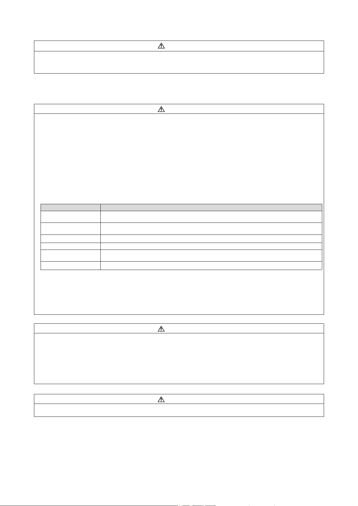
Injury Prevention
CAUTION
CAUTION
Operating condition FR-F820/F840/F842
Surrounding air
temperature
LD rating: –10°C to +50°C (non-freezing)
SLD rating: –10°C to +40°C (non-freezing)
Ambient humidity With circuit board coating (conforming to IEC 60721-3-3 3C2/3S2): 95% RH or less (non-condensing),
Without circuit board coating: 90% RH or less (non-condensing)
Storage temperature
–20°C to +65°C
*1
Atmosphere Indoors (free from corrosive gas, flammable gas, oil mist, dust and dirt)
Altitude Maximum 1000m above sea level for standard operation. After that derate by 3% for
every extra 500m up to 2500m (91%)
Vibration
5.9m/s² or less
*2
at 10 to 55Hz (directions of X, Y, Z axes)
CAUTION
CAUTION
Apply only the voltage specified in the instruction manual to each terminal. Otherwise, burst, damage, etc. may occur.
Ensure that the cables are connected to the correct terminals. Otherwise, burst, damage, etc. may occur.
Always make sure that polarity is correct to prevent damage, etc. Otherwise, burst, damage, etc. may occur.
While power is on or for some time after power-off, do not touch the inverter as it is hot and you may get burnt.
Additional Instructions
The following instructions must be also followed. If the product is handled incorrectly, it may cause unexpected fault, an injury, or an
electric shock.
Transportation and installation
Any person who is opening a package using a sharp object, such as a knife and cutter, must wear gloves to prevent injuries caused
by the edge of the sharp object.
When carrying products, use correct lifting gear to prevent injury.
Do not stand or rest heavy objects on the product.
Do not stack the inverter boxes higher than the number recommended.
When carrying the inverter, do not hold it by the front cover or setting dial; it may fall off or fail.
During installation, caution must be taken not to drop the inverter as doing so may cause injuries.
Ensure that installation position and material can withstand the weight of the inverter. Install according to the information in the instruction
manual.
Do not install the product on a hot surface.
Check the inverter mounting orientation is correct.
The inverter must be installed on a strong surface securely with screws so that it will not drop.
Do not install or operate the inverter if it is damaged or has parts missing. This can result in breakdowns.
Prevent other conductive bodies such as screws and metal fragments or other flammable substance such as oil from entering the
inverter.
As the inverter is a precision instrument, do not drop or subject it to impact.
Use the inverter under the following environmental conditions. Otherwise, the inverter may be damaged.
*1
Temperature applicable for a short time, e.g. in transit.
*2
2.9m/s² or less for the FR-F840-04320(185K) or higher
If halogen-based materials (fluorine, chlorine, bromine, iodine, etc.) infiltrate into a Mitsubishi Electric product, the product will be
damaged. Halogen-based materials are often included in fumigant, which is used to sterilize or disinfect wooden packages. When
packaging, prevent residual fumigant components from being infiltrated into Mitsubishi Electric products, or use an alternative
sterilization or disinfection method (heat disinfection, etc.) for packaging. Sterilization of disinfection of wooden package should also
be performed before packaging the product.
To prevent a failure, do not use the inverter with a part or material containing halogen flame retardant including bromine.
Wiring
Do not install assemblies or components (e. g. power factor correction capacitors) on the inverter output side, which are not approved
from Mitsubishi Electric. These devices on the inverter output side may be overheated or burn out.
The direction of rotation of the motor corresponds to the direction of rotation commands (STF/STR) only if the phase sequence (U, V,
W) is maintained.
PM motor terminals (U, V, W) hold high-voltage while the PM motor is running even after the power is turned OFF. Before wiring, the
PM motor must be confirmed to be stopped. Otherwise you may get an electric shock.
Never connect a PM motor to the commercial power supply.
Applying the commercial power supply to input terminals (U,V, W) of a PM motor will burn the PM motor. The PM motor must be
connected with the output terminals (U, V, W) of the inverter.
Test operation and adjustment
Before starting operation, confirm and adjust the parameters. A failure to do so may cause some machines to make unexpected
motions.
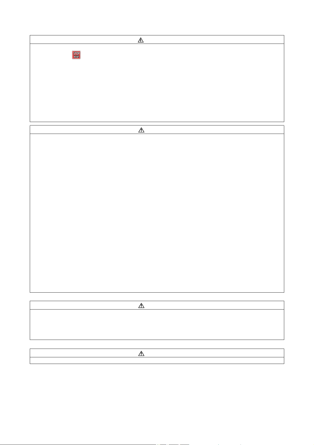
Operation
WARNING
CAUTION
CAUTION
CAUTION
When you have chosen the retry function, stay away from the equipment as it will restart suddenly after an alarm stop.
Since pressing the key may not stop output depending on the function setting status, provide a circuit and switch separately to
make an emergency stop (power off, mechanical brake operation for emergency stop, etc).
Make sure that the start signal is off before resetting the inverter alarm. A failure to do so may restart the motor suddenly.
Do not use a PM motor for an application where the PM motor is driven by its load and runs at a speed higher than the maximum
motor speed.
The inverter can be started and stopped via the serial port communications link or the field bus. However, please note that depending
on the settings of the communications parameters it may not be possible to stop the system via these connections if there is an error
in the communications system or the data line. In configurations like this it is thus essential to install additional safety hardware that
makes it possible to stop the system in an emergency (e.g. controller inhibit via control signal, external motor contactor etc). Clear and
unambiguous warnings about this must be posted on site for the operating and service staff.
Use this inverter only with three-phase induction motors or with a PM motor. Connection of any other electrical equipment to the
inverter output may damage the inverter as well as the equipment.
Do not modify the equipment.
Do not perform parts removal which is not instructed in this manual. Doing so may lead to fault or damage of the inverter.
The electronic thermal relay function does not guarantee protection of the motor from overheating. It is recommended to install both
an external thermal and PTC thermistor for overheat protection.
Do not use a magnetic contactor on the inverter input for frequent starting/stopping of the inverter. Otherwise, the life of the inverter
decreases.
Use a noise filter to reduce the effect of electromagnetic interference and follow the accepted EMC procedures for proper installation
of frequency inverters. Otherwise nearby electronic equipment may be affected.
Take appropriate measures regarding harmonics. Otherwise this can endanger compensation systems or overload generators.
When driving a 400V class motor by the inverter, the motor must be an insulation-enhanced motor or measures must be taken to
suppress surge voltage. Surge voltage attributable to the wiring constants may occur at the motor terminals, deteriorating the
insulation of the motor.
Use a motor designed for inverter operation. (The stress for motor windings is bigger than in line power supply).
When parameter clear or all clear is performed, set again the required parameters before starting operations. Each parameter returns
to the initial value.
The inverter can be easily set for high-speed operation. Before changing its setting, fully examine the performances of the motor and
machine.
The DC braking function of the frequency inverter is not designed to continuously hold a load. Use an electro-mechanical holding
brake on the motor for this purpose.
Before running an inverter which had been stored for a long period, always perform inspection and test operation.
For prevention of damage due to static electricity, touch nearby
your body.
Only one PM motor can be connected to an inverter.
A PM motor must be used under PM motor control. When operating with PM motor control, a synchronous motor, induction motor or
synchronous induction motor may only be used when it is a PM motor.
Do not connect a PM motor under the induction motor control settings (initial settings). Do not use an induction motor under the PM
motor control settings. It will cause a failure.
In the system with a PM motor, the inverter power must be turned ON before closing the contacts of the contactor at the output side.
When the emergency drive operation is performed, the operation is continued or the retry is repeated even when a fault occurs, which
may damage or burn the inverter and motor. Before restarting the normal operation after using the emergency drive function, make
sure that the inverter and motor have no fault.
In order to protect the inverter and the system against unauthorized access by external systems via network, take security measures
including firewall settings.
Depending on the network environment, the inverter may not operate as intended due to delays or disconnection in communication.
Carefully consider the conditions and safety for the inverter on site.
Emergency stop
metal before touching this product to eliminate static electricity from
Provide a safety backup such as an emergency brake which will prevent the machine and equipment from hazardous conditions if the
When the breaker on the inverter primary side trips, check for the wiring fault (short circuit), damage to internal parts of the inverter,
When the protective function is activated (i. e. the frequency inverter switches off with an error message), take the corresponding
Maintenance, inspection and parts replacement
Do not carry out a megger (insulation resistance) test on the control circuit of the inverter. It will cause a failure.
inverter fails.
etc. Identify the cause of the trip, then remove the cause and power on the breaker.
corrective action as described in the inverter manual, then reset the inverter, and resume operation.

Disposing of the inverter
CAUTION
Treat as industrial waste.
General instructions
Many of the diagrams and drawings in instruction manuals show the inverter without a cover, or partially open. Never run the inverter in
this status. Always replace the cover and follow instruction manuals when operating the inverter. For more details on the PM motor,
refer to the Instruction Manual of the PM motor.
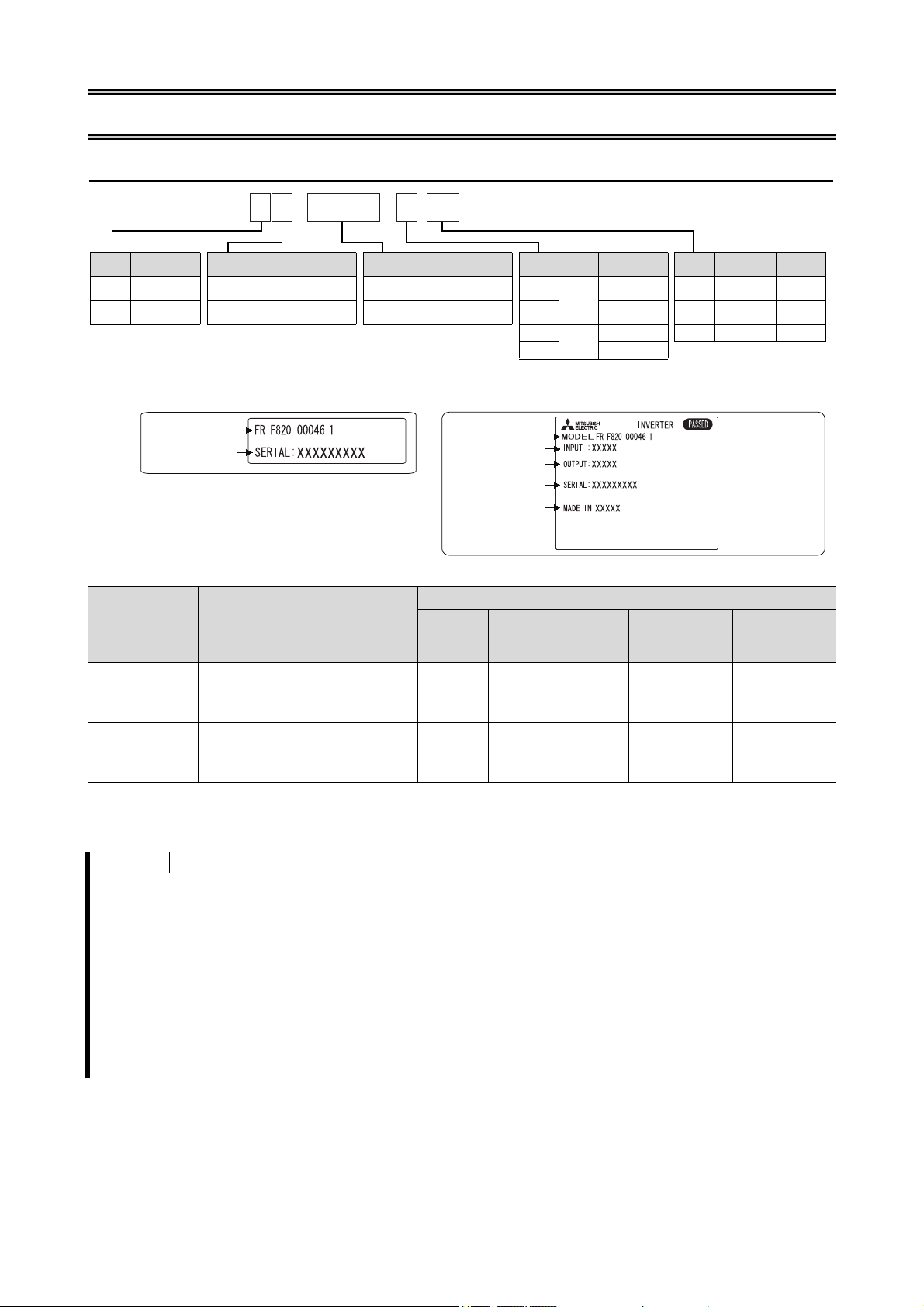
1 INSTALLATION AND INSTRUCTIONS
F R - F 8 2 0 -
00046
- 1
1.1 Inverter Type
Symbol Voltage class Symbol Structure, functionality Symbol Description Symbol Typ e
*1
Communication type
Symbol
Circuit board
coating
*3
Plated
conductor
2 200V class 0 Standard model
00023 to
12120
Inverter SLD rated current [A]
1
FM
Standard Without Without Without
4 400V class 2 Separated converter type
0.75 to
560K
Inverter LD rated capacity
[kW]
E1
Ethernet
*2
-60 With Without
2
CA
Standard
-06
*4
With With
E2
Ethernet
*2
Capacity plate Rating plate
Inverter model
Serial number
Inverter model
Input rating
Output rating
Serial number
Country of origin
*1
Specification differs by the type. Major differences are shown in the table below.
Initial setting
Type Monitor output
FM
(terminal FM
equipped model)
CA
(terminal CA
equipped model)
*2
Model with built-in Ethernet board (FR-A8ETH)
*3
Conforming to IEC60721-3-3 3C2/3S2
*4
For the FR-F820-00340(7.5K) or higher, and the FR-F840-00170(7.5K) or higher
Terminal FM: pulse train output
Terminal AM: analog voltage output
Terminal CA: analog current output
Terminal AM: analog voltage output
(0 to ±10VDC)
(0 to 20mADC)
(0 to ±10VDC)
Built-in
EMC filter
Control
logic
Rated
frequency
OFF Sink logic 60Hz 9999
ON Source
logic
50Hz 8888
Pr. 19 "Base
frequency
voltage"
(same as the
power supply
voltage)
(95% of the
power supply
voltage)
Pr.570 "Multiple
rating setting"
1
(LD rating)
0
(SLD rating)
Notes
The rating plate shows the inverter rated current in SLD operation (Super Light Duty). The overload current rating at
SLD is 110% of the rated current for 60s and 120% for 3s at surrounding air temperature of max. 40°C.
The inverter model name used in this installation guide consists of the inverter model, e. g. FR-F820-00046-1 and the
applicable motor capacity in brackets specified in [kW]. This approach helps for better understanding and for
choosing the right motor. For further specification details like capacity, current or overload current rating refer to
chapter 7.
In this installation guideline the following common designations are used for the different types of inverter models:
–FR-F80: Standard model
–FR-F82: Separated converter type
–FR-F8-E: Model with built-in Ethernet board (FR-A8ETH)
For selecting the right frequency inverter you should know details of your application and especially the load
characteristic.
1
INSTALLATION AND INSTRUCTIONS
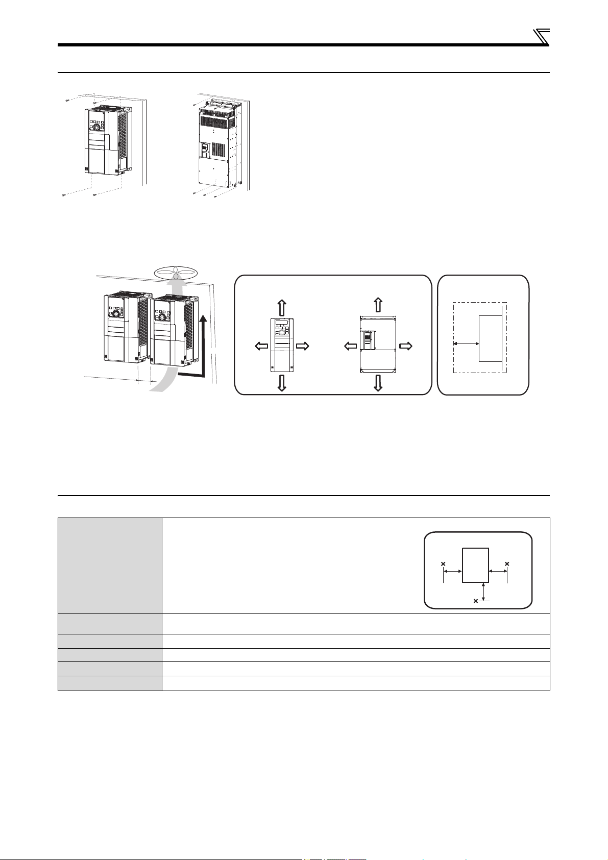
Fix six positions for the
FR-F
840-04320(185K) or higher and for the
FR-F842 models (separated converter type).
FR-F820-03160(75K) or lower,
FR-F840-01800(75K) or lower
FR-F820-03800(90K) or higher,
FR-F840-02160(90K) or higher,
FR-F842
10cm 20cm
10cm 5cm
*1, *2
10cm
10cm 20cm
5cm
*1, *3
Inverter
5cm
*1, *2
Ver tica l
R
e
f
e
r
t
o
t
h
e
c
i
e
a
r
a
n
c
e
s
h
o
w
n
o
n
t
h
e
r
i
g
h
t
Clearances (side) Clearances (front)
5 cm5 cm
5 cm
Inverter
x = Measurement position
1.2 Installation of the inverter
Installation on the enclosure
Install the inverter on a strong surface securely with bolts.
Leave enough clearances and take cooling measures.
Avoid places where the inverter is subjected to direct sunlight, high temperature and high humidity.
Install the inverter on a nonflammable surface.
When encasing multiple inverters, install them in parallel as a cooling measure.
*1
For the FR-F820-00250(5.5K) or lower and FR-F840-00126(5.5K) or lower, allow 1cm or more clearance.
*2
When using the FR-F820-01250(30K) or lower and FR-F840-00620(30K) or lower at the surrounding air temperature of 40°C or less
(30°C or less for the SLD rated inverter), side-by-side installation (0cm clearance) is available.
*3
For replacing the cooling fan of the FR-F840-04320(185K) or higher, and of the FR-F842 models, 30cm of space is necessary in front
of the inverter. Refer to the Instruction Manual for fan replacement.
1.3 Environment
Before installation, check that the environment meets following specifications:
Enclosure
Surrounding air
temperature
*6, *7
Ambient humidity
Storage temperature
Atmosphere
Altitude
Vibration
*4
Temperature applicable for a short time, e.g. in transit.
*5
For the installation at an altitude above 1,000m up to 2,500m, derate the rated current 3% per 500m.
*6
Surrounding air temperature is a temperature measured at a measurement position in an enclosure. Ambient temperature is a
temperature outside an enclosure.
*7
For the amount of heat generated by the inverter unit, refer to the Technical News (MF-Z-118) contained in the enclosed CD-ROM.
*8
2.9m/s² or less for the FR-F840-04320(185K) or higher
LD rating: –10°C to +50°C (non-freezing)
SLD rating: –10°C to +40°C (non-freezing)
With circuit board coating (conforming to IEC 60721-3-3 3C2/3S2): 95% RH or less (non-condensing),
Without circuit board coating: 90% RH or less (non-condensing)
–20°C to +65°C
*4
Indoors (No corrosive and flammable gases, oil mist, dust and dirt)
Maximum 2,500m above sea level
5.9m/s² or less
*8
at 10 to 55Hz (directions of X, Y, Z axes)
*5
2
INSTALLATION AND INSTRUCTIONS
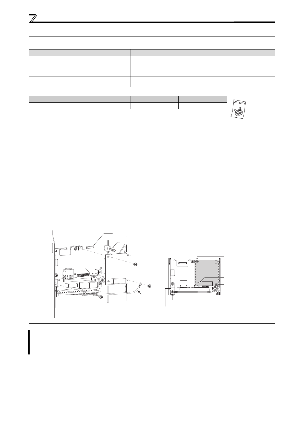
Option connector 1
Spac er
Ethernet board
earth plate
Earth cable
Mounting screw
Spac er
Spac er
Earth cable
Mounting screw
Mounting screw
Ethernet board
earth plate
Spac er
Example FR-A8NC
1.4 Accessory
Fan cover fixing screws
These screws are necessary for compliance with the EU Directives (refer to page 52).
Capacity Screw size (mm) Quantity
FR-F820-00105(2.2K) to FR-F820-00250(5.5K)
FR-F840-00083(3.7K), FR-F840-00126(5.5K)
FR-F820-00340(7.5K) to FR-F820-00490(11K)
FR-F840-00170(7.5K) to FR-F840-00250(11K)
FR-F820-00630(15K) to FR-F820-01250(30K)
FR-F840-00310(15K), FR-F840-00620(30K)
M3 × 35 1
M3 × 35 2
M4 × 40 2
Eyebolt for hanging the inverter
Capacity Eyebolt size Quantity
FR-F840-04320(185K) to FR-F840-06830(315K) M12 2
Earthing (grounding) cable (1): For connection with a communication option
CD-ROM (1): Including the Instruction Manual (Detailed) and other documents
1.5 Installing a communication option (FR-F800-E)
To use a communication option, the enclosed earthing (grounding) cable needs to be installed. Install the cable according
to the following procedure:
햲 Insert spacers into the mounting holes that will not be tightened with the option mounting screws.
햳 Fit the connector of the communication option to the guide of the connector of the inverter, and insert the option as far
as it goes. (Insert it to the inverter option connector 1.)
햴 Remove the mounting screw (lower) of the Ethernet board earth plate. Fit the one terminal of the earthing (grounding)
cable on the Ethernet board earth plate and fix it securely to the inverter with the mounting screw (tightening torque
0.33Nm to 0.40Nm).
햵 Fix the left part of the communication option securely with the option mounting screw, and place another terminal of the
earthing (grounding) cable on the right part of the option and fix the cable terminal and the option with the option
mounting screw (tightening torque 0.33Nm to 0.40Nm).
If the screws are not tightened properly, the connector may not be inserted deep enough. Check the connector.
Notes
The number and shape of the spacers used differ depending on the communication option type. Refer to the
Instruction Manual of each communication option for details.
The earth plate enclosed with a communication option is not used.
3
2WIRING
F/C
(CA)
MCCB
R/L1
S/L2
T/L3
R1/L11
S1/L21
PC
10E(+10V)
10(+5V)
2
2
3
1
1
4
C1
B1
A1
U
V
W
P1
(-)
(+)
(-)
(+)
AM
5
MC
C2
B2
A2
M
TXD+
TXD-
RXD+
RXD-
GND
(SG)
SINK
SOURCE
STF
STR
STP(STOP)
RH
RM
RL
JOG
RT
MRS
RES
AU
CS
SD
RUN
SU
IPF
OL
FU
SE
(+)
(-)
5
ON
OFF
+24
VCC
(+)
(-)
PX PR N/-P/+
ON
42
OFF
SO
SOC
S1
S2
PC
SD
SIC
SD
P1 P3 PR N/-P/+
24V
24V
Source logic
Main circuit terminal
Control circuit terminal
Jumper
Earth
Earth
3-phase
AC power
supply
EMC filter
ON/OFF
connector
Main circuit
Control circuit
Control input signals
*3
Forward rotation start
Reverse rotation start
Start self-holding selection
High speed
Middle
speed
Low speed
Multi-speed
selection
Jog operation
Second function selection
Output stop
Reset
Terminal 4 input selection
(Current input selection)
*11
Safety stop signal
(Common for external power
supply transistor)
Frequency setting signals (Analog)
Auxiliary input
Terminal 4 input
(Current input)
0 to 5VDC
0 to ±10VDC
4 to 20mADC
0 to 10VDC
4 to 20mADC
0 to ±5VDC
0 to 5VDC
0 to 10VDC
PU
connector
Connector for plug-in option
connection
Connector 1
Terminating
resistor
Relay output 1
(Fault output)
Relay output 2
Running
Instantaneous power failure
Up to frequency
Overload
Frequency detection
Open collector output common
Sink/source common
Analog current output
(0 to 20mADC)
Analog signal output
(0 to ±10VDC)
RS-485 terminals
*12
Data transmission
Data reception
Frequency setting
potentiometer
½W, 1kΩ
*6
Inrush
current limit
circuit
Open collector output
*10
Relay output
*9
Voltage/current
input switch
(Analog common)
Jumper
Brake unit
(option)
FR-F820-00770(18.5K)–01250(30K)
FR-F840-00470(22K)–01800(75K)
Motor
Earth
DC reactor
(FR-HEL)
*1
DC reactor
(FR-HEL)
*1
Brake unit
(option)
USB
mini B
connector
Earth
24V external power supply input
Common terminal
Connector 2
*13
Connector 3
Shorting wire
Safety stop input (Channel 1)
Safety stop input (Channel 2)
Safety stop input common
Output
shutoff circuit
Initial value
Initial value
selectable
Initial value
selectable
selectable
GND
Safety monitor output common
5V (Permissible load
current 100mA)
Jumper
*2
Contact input common
24VDC power supply
Safety monitor output
USB A
connector
Jumper
Ethernet
connector
*13
*4
*5
*5
*5
*5
*7
*8
Inrush current
limit circuit
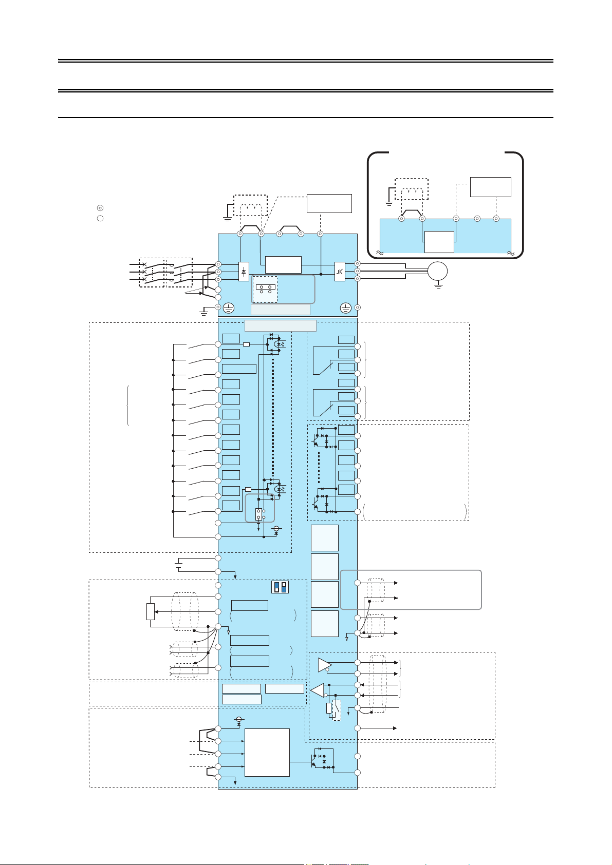
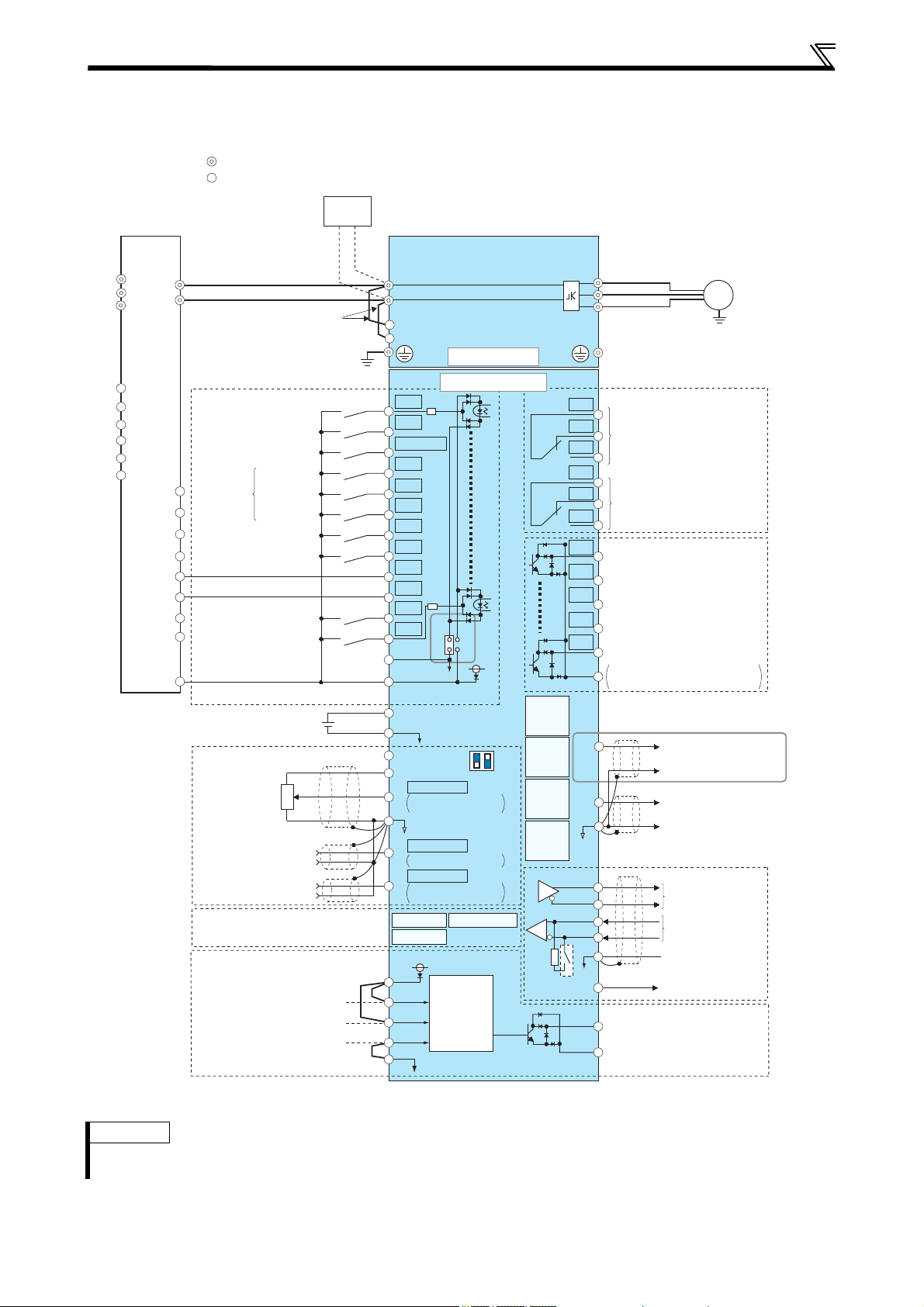
2.1 Terminal connection diagrams
2.1.1 FR-F820/F840(-E)
CA type
For footnotes *1 to *13 refer to next page.
4

WIRING
*1
For the FR-F820-03160(75K) or higher, and the FR-F840-01800(75K) or higher, always connect a DC reactor (FR-HEL), which is
available as an option.
(When selecting a DC reactor, refer to page 47, and select one suitable for the applicable motor capacity.) When a DC reactor is
connected to the FR-F820-02330(55K) or lower or the FR-F840-01160(55K) or lower, if a jumper is installed across the terminals P1
and P/+, remove the jumper before installing the DC reactor.
*2
When using separate power supply for the control circuit, remove the jumper between R1/L11 and S1/L21.
*3
No input voltage is allowed for these terminals.The function of these terminals can be changed with the input terminal assignment (Pr.
178 to Pr. 189). (Refer to page 29.)
*4
Terminal JOG is also used as the pulse train input terminal. Use Pr. 291 to choose JOG or pulse.
*5
Terminal input specifications can be changed by analog input specification switchover (Pr. 73, Pr. 267). To input a voltage, set the
voltage/current input switch OFF. To input a current, set the voltage/current input switch ON. Terminals 10 and 2 are also used as a
PTC input terminal (Pr. 561). (Refer to the FR-F800 Instruction Manual.)
*6
It is recommended to use 2W, 1kΩ when the frequency setting signal is changed frequently.
*7
Do not use terminals PR and PX. Do not remove the jumper connected to terminals PR and PX.
*8
Do not connect the DC power supply (under DC feeding mode) to terminal P3.
*9
The function of these terminals can be changed with the output terminal assignment (Pr. 195, Pr. 196). (Refer to page 29.)
*10
The function of these terminals can be changed with the output terminal assignment (Pr. 190 to Pr. 194). (Refer to page 29.)
*11
No function is assigned in the initial status. Assign the function using Pr. 186 "CS terminal function selection".(Refer to page 29.)
*12
Upon delivery the FR-F800-E inverter models are not equipped with the RS-485 terminal block.
*13
For FR-F800-E: The option connector 2 cannot be used because the Ethernet board is installed in the initial status. The Ethernet
board must be removed to install a plug-in option to the option connector 2. (However, Ethernet communication is disabled in that
case.)
CAUTION
To prevent a malfunction due to noise, keep the signal cables more than 10cm away from the power cables. Also, separate the main
circuit cables at the input side from the main circuit cables at the output side.
After wiring, wire offcuts must not be left in the inverter.
Wire offcuts can cause an alarm, failure or malfunction. Always keep the inverter clean.
When drilling mounting holes in a control box etc., take care not to allow chips and other foreign matter to enter the inverter.
Set the voltage/current input switch in the correct position. An incorrect setting may cause a fault, failure or malfunction.
5
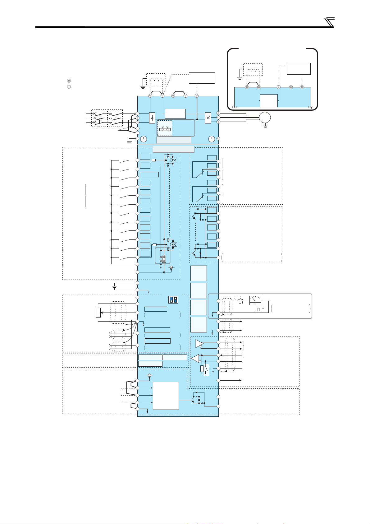
WIRING
MCCB
R/L1
S/L2
T/L3
R1/L11
S1/L21
PC
10E(+10V)
10(+5V)
2
2
3
1
1
4
F/C
(FM)
SD
C1
B1
A1
U
V
W
P1
+-
(-)
(+)
AM
5
MC
C2
B2
A2
M
TXD+
TXD-
RXD+
RXD-
GND
(SG)
SINK
SOURCE
STF
STR
STP(STOP)
RH
RM
RL
JOG
RT
MRS
RES
AU
CS
SD
RUN
SU
IPF
OL
FU
SE
(+)
(-)
5
ON
OFF
+24
SD
VCC
(+)
(-)
PX PR N/-P/+
ON
4
2
OFF
SO
SOC
S1
S2
PC
SD
SIC
P1 P3 PR N/-P/+
24V
24V
Sink logic
Main circuit terminal
Control circuit terminal
Jumper
Earth
Earth
3-phase
AC power
supply
EMC filter
ON/OFF
connector
Main circuit
Control circuit
Control input signals
*3
Forward rotation start
Reverse rotation start
Start self-holding selection
High speed
Middle
speed
Low speed
Multi-speed
selection
Jog operation
Second function selection
Output stop
Reset
Terminal 4 input selection
(Current input selection)
*13
Safety stop signal
24VDC power supply
(Common for external power supply
transistor)
Frequency setting signals (Analog)
Auxiliary input
Terminal 4 input
(Current input)
0 to 5VDC
0 to ±10VDC
4 to 20mADC
0 to 10VDC
4 to 20mADC
0 to ±5VDC
0 to 5VDC
0 to 10VDC
PU
connector
Connector for plug-in option
connection
Connector 1
Terminating
resistor
Relay output 1
(Fault output)
Relay output 2
Running
Instantaneous power failure
Up to frequency
Overload
Frequency detection
Open collector output common
Sink/source common
Indicator
(Frequency meter, etc.)
Analog signal output
(0 to ±10VDC)
Data transmission
Data reception
Frequency setting
potentiometer
½W, 1k
Ω
*6
Inrush current
limit circuit
Open collector output
*10
Relay output
*9
Voltage/current
input switch
(Analog common)
Jumper
Brake unit
(option)
FR-F820-00770(18.5K)–01250(30K)
FR-F840-00470(22K)–01800(75K)
Motor
Earth
DC reactor
(FR-HEL)
*1
DC reactor
(FR-HEL)
*1
Brake unit
(option)
USB A
connector
USB
mini B
connector
Moving coil type
1mA full-scale
Earth
24V external power supply input
Common terminal
Connector 3
Shorting wire
Safety stop input (Channel 1)
Safety stop input (Channel 2)
Safety stop input common
Output
shutoff
circuit
Initial value
Initial value
selectable
Initial value
selectable
selectable
GND
Safety monitor output
Safety monitor output common
5V (Permissible load
current 100mA)
Jumper
*2
Contact input common
Calibration
resistor
*12
Jumper
RS-485 terminals
*14
Inrush
current
limit circuit
Connector 2
*15
Ethernet
connector
*15
*4
*5
*5
*5
*5
*7
*8
*11
FM type
For footnotes *1 to *15 refer to next page.
6

WIRING
*1
For the FR-F820-03160(75K) or higher, and the FR-F840-01800(75K) or higher always connect a DC reactor (FR-HEL), which is
available as an option.
(When selecting a DC reactor, refer to page 47, and select one suitable for the applicable motor capacity.) When a DC reactor is
connected to the FR-F820-2330(55K) or lower or the FR-F840-01160(55K) or lower, if a jumper is installed across the terminals P1
and P/+, remove the jumper before installing the DC reactor.
*2
When using separate power supply for the control circuit, remove the jumper between R1/L11 and S1/L21.
*3
No input voltage is allowed for these terminals. The function of these terminals can be changed with the input terminal assignment
(Pr. 178 to Pr. 189). (Refer to page 29.)
*4
Terminal JOG is also used as the pulse train input terminal. Use Pr. 291 to choose JOG or pulse.
*5
Terminal input specifications can be changed by analog input specification switchover (Pr. 73, Pr. 267). To input a voltage, set the
voltage/current input switch OFF. To input a current, set the voltage/current input switch ON. Terminals 10 and 2 are also used as a
PTC input terminal (Pr. 561). (Refer to the FR-F800 Instruction Manual.)
*6
It is recommended to use 2W, 1kΩ when the frequency setting signal is changed frequently.
*7
Do not use terminals PR and PX. Do not remove the jumper connected to terminals PR and PX.
*8
Do not connect the DC power supply (under DC feeding mode) to terminal P3.
*9
The function of these terminals can be changed with the output terminal assignment (Pr. 195, Pr. 196). (Refer to page 29.)
*10
The function of these terminals can be changed with the output terminal assignment (Pr. 190 to Pr. 194). (Refer to page 29.)
*11
The terminal F/C (FM) can be used to output pulse trains as open collector output by setting Pr. 291.
*12
Not required when calibrating the scale with the operation panel.
*13
No function is assigned in the initial status. Assign the function using Pr. 186 "CS terminal function selection". (Refer to page 29.)
*14
Upon delivery the FR-F800-E inverter models are not equipped with the RS-485 terminal block.
*15
For FR-F800-E: The option connector 2 cannot be used because the Ethernet board is installed in the initial status. The Ethernet
board must be removed to install a plug-in option to the option connector 2. (However, Ethernet communication is disabled in that
case.)
CAUTION
To prevent a malfunction due to noise, keep the signal cables more than 10cm away from the power cables. Also, separate the main
circuit cables at the input side from the main circuit cables at the output side.
After wiring, wire offcuts must not be left in the inverter.
Wire offcuts can cause an alarm, failure or malfunction. Always keep the inverter clean.
When drilling mounting holes in a control box etc., take care not to allow chips and other foreign matter to enter the inverter.
Set the voltage/current input switch in the correct position. An incorrect setting may cause a fault, failure or malfunction.
7
R1/L11
S1/L21
PC
10E(+10V)
10(+5V)
2
2
3
1
1
4
C1
B1
A1
U
V
W
C2
B2
A2
M
SINK
SOURCE
STF
STR
STP(STOP)
RH
RM
RL
JOG
RT
MRS
X10
RES
AU
CS
SD
RUN
SU
IPF
OL
FU
SE
(+)
(-)
5
(+)
(-)
N/-
P/+
ON
OFF
42
SO
SOC
S1
S2
PC
SD
SIC
+24
SD
24V
24V
(-)
(+)
(-)
(+)
AM
5
F/C
(CA)
RDA
RDI
RSO
SE
N/-
P/+
IPF
RDB
FAN
R/L1
S/L2
T/L3
OH
RES
SD
PC
+24
C1
B1
A1
TXD+
TXD-
RXD+
RXD-
GND
(SG)
VCC
Source logic
Main circuit terminal
Control circuit terminal
Earth
Main circuit
Control circuit
Control input signals
*2
Forward rotation start
Reverse rotation start
Start self-holding selection
High speed
Middle
speed
Low speed
Multi-speed
selection
Jog operation
Second function selection
Output stop
Reset
Terminal 4 input selection
(Current input selection)
*5
Safety stop signal
(Common for external power
supply transistor)
Frequency setting signals (Analog)
Auxiliary input
Terminal 4 input
(Current input)
0 to 5VDC
0 to ±10VDC
4 to 20mADC
0 to 10VDC
4 to 20mADC
0 to ±5VDC
0 to 5VDC
0 to 10VDC
PU
connector
Connector for plug-in option
connection
Connector 1
Terminating
resistor
Relay output 1
(Fault output)
Relay output 2
Running
*10
Up to frequency
Overload
Frequency detection
Open collector output common
Sink/source common
Analog current output
(0 to 20mADC)
Analog signal output
(0 to ±10VDC)
RS-485 terminals
*11
Data transmission
Data reception
Frequency setting
potentiometer
½W, 1kΩ
*7
Open collector output
*9
Relay output
*8
Voltage/current
input switch
(Analog common)
Brake unit
(option)
Motor
USB
mini B
connector
Earth
24V external power supply input
Common terminal
Connector 2
*12
Connector 3
Shorting wire
Safety stop input (Channel 1)
Safety stop input (Channel 2)
Safety stop input common
Output
shutoff circuit
Initial value
Initial value
selectable
Initial value
selectable
selectable
GND
Safety monitor output common
5V (Permissible load
current 100mA)
Jumper
*1
Contact input common
24VDC power supply
Safety monitor output
USB A
connector
Ethernet
connector
*12
*3
*6
*6
*6
*6
Converter
unit
*4
WIRING
2.1.2 FR-F842(-E)
CA type
For footnotes *1 to *12 refer to next page.
8
Note
The FR-F842 models must be operated with a converter unit (FR-CC2), which has to be operated separately. For more
details about the installation of the converter unit please refer to the corresponding FR-CC2 Instruction Manual.

WIRING
*1
The terminals R1/L11 and S1/L21 are connected to the terminals P/+ and N/– with a jumper respectively. When using separate power
supply for the control circuit, remove the jumper between R1/L11 and S1/L21.
*2
No input voltage is allowed for these terminals.The function of these terminals can be changed with the input terminal assignment (Pr.
178 to Pr. 189). (Refer to page 29.)
*3
Terminal JOG is also used as the pulse train input terminal. Use Pr. 291 to choose JOG or pulse.
*4
The X10 signal (NC contact input specification) is assigned to the terminal MRS in the initial setting. Set Pr. 599 = "0" to change the
input specification of the X10 signal to NO contact.
*5
No function is assigned in the initial status. Assign the function using Pr. 186 "CS terminal function selection".(Refer to page 29.)
*6
Terminal input specifications can be changed by analog input specification switchover (Pr. 73, Pr. 267). To input a voltage, set the
voltage/current input switch OFF. To input a current, set the voltage/current input switch ON. Terminals 10 and 2 are also used as a
PTC input terminal (Pr. 561). (Refer to the FR-F800 Instruction Manual.)
*7
It is recommended to use 2W, 1kΩ when the frequency setting signal is changed frequently.
*8
The function of these terminals can be changed with the output terminal assignment (Pr. 195, Pr. 196). (Refer to page 29.)
*9
The function of these terminals can be changed with the output terminal assignment (Pr. 190 to Pr. 194). (Refer to page 29.)
*10
No function is assigned in the initial status. Assign the function using Pr.192. (Refer to page 29.)
*11
Upon delivery the FR-F800-E inverter models are not equipped with the RS-485 terminal block.
*12
For FR-F800-E: The option connector 2 cannot be used because the Ethernet board is installed in the initial status. The Ethernet
board must be removed to install a plug-in option to the option connector 2. (However, Ethernet communication is disabled in that
case.)
CAUTION
To prevent a malfunction due to noise, keep the signal cables more than 10cm away from the power cables. Also, separate the main
circuit cables at the input side from the main circuit cables at the output side.
After wiring, wire offcuts must not be left in the inverter.
Wire offcuts can cause an alarm, failure or malfunction. Always keep the inverter clean.
When drilling mounting holes in a control box etc., take care not to allow chips and other foreign matter to enter the inverter.
Set the voltage/current input switch in the correct position. An incorrect setting may cause a fault, failure or malfunction.
9

R1/L11
S1/L21
PC
10E(+10V)
10(+5V)
2
2
3
1
1
4
F/C
(FM)
SD
C1
B1
A1
U
V
W
+-
(-)
(+)
AM
5
C2
B2
A2
M
SINK
SOURCE
STF
STR
STP(STOP)
RH
RM
RL
JOG
RT
MRS
X10
RES
AU
CS
SD
RUN
SU
IPF
OL
FU
SE
(+)
(-)
5
(+)
(-)
N/-
P/+
ON
OFF
42
SO
SOC
S1
S2
PC
SD
SIC
+24
SD
RDA
RDI
RSO
SE
N/-
P/+
IPF
RDB
FAN
R/L1
S/L2
T/L3
OH
RES
SD
PC
+24
C1
B1
A1
24V
24V
TXD+
TXD-
RXD+
RXD-
GND
(SG)
VCC
Sink logic
Main circuit terminal
Control circuit terminal
Earth
Main circuit
Control circuit
Control input signals
*2
Forward rotation start
Reverse rotation start
Start self-holding selection
High speed
Middle
speed
Low speed
Multi-speed
selection
Jog operation
Second function selection
Output stop
Reset
Terminal 4 input selection
(Current input selection)
*5
Safety stop signal
24VDC power supply
(Common for external power supply
transistor)
Frequency setting signals (Analog)
Auxiliary input
Terminal 4 input
(Current input)
0 to 5VDC
0 to ±10VDC
4 to 20mADC
0 to 10VDC
4 to 20mADC
0 to ±5VDC
0 to 5VDC
0 to 10VDC
PU
connector
Connector for plug-in option
connection
Connector 1
Te rm i nating
resistor
Relay output 1
(Fault output)
Relay output 2
Running
*10
Up to frequency
Overload
Frequency detection
Open collector output common
Sink/source common
Indicator
(Frequency meter,
etc.)
Analog signal output
(0 to ±10VDC)
Data transmission
Data reception
Frequency setting
potentiometer
½W, 1kΩ
*7
Open collector output
*9
Relay output
*8
Voltage/current
input switch
(Analog common)
Brake unit
(option)
Motor
USB A
connector
USB
mini B
connector
Moving coil type
1mA full-scale
Earth
24V external power supply input
Common terminal
Connector 3
Shorting wire
Safety stop input (Channel 1)
Safety stop input (Channel 2)
Safety stop input common
Output
shutoff circuit
Initial value
Initial value
selectable
Initial value
selectable
selectable
GND
Safety monitor output
Safety monitor output common
5V (Permissible load
current 100mA)
Jumper
*1
Contact input common
Calibration
resistor
*12
RS-485 terminals
*13
Connector 2
*14
Ethernet
connector
*14
*4
*6
*6
*6
*6
*11
Converter
unit
*3
WIRING
FM type
For footnotes *1 to *14 refer to next page.
Note
The FR-F842 models must be operated with a converter unit (FR-CC2), which has to be operated separately. For more
details about the installation of the converter unit please refer to the corresponding FR-CC2 Instruction Manual.
10

WIRING
*1
The terminals R1/L11 and S1/L21 are connected to the terminals P/+ and N/– with a jumper respectively. When using separate power
supply for the control circuit, remove the jumper between R1/L11 and S1/L21.
*2
No input voltage is allowed for these terminals. The function of these terminals can be changed with the input terminal assignment
(Pr. 178 to Pr. 189). (Refer to page 29.)
*3
Terminal JOG is also used as the pulse train input terminal. Use Pr. 291 to choose JOG or pulse.
*4
The X10 signal (NC contact input specification) is assigned to the terminal MRS in the initial setting. Set Pr. 599 = "0" to change the
input specification of the X10 signal to NO contact.
*5
No function is assigned in the initial status. Assign the function using Pr. 186 "CS terminal function selection". (Refer to page 29.)
*6
Terminal input specifications can be changed by analog input specification switchover (Pr. 73, Pr. 267). To input a voltage, set the
voltage/current input switch OFF. To input a current, set the voltage/current input switch ON. Terminals 10 and 2 are also used as a
PTC input terminal (Pr. 561). (Refer to the FR-F800 Instruction Manual.)
*7
It is recommended to use 2W, 1kΩ when the frequency setting signal is changed frequently.
*8
The function of these terminals can be changed with the output terminal assignment (Pr. 195, Pr. 196). (Refer to page 29.)
*9
The function of these terminals can be changed with the output terminal assignment (Pr. 190 to Pr. 194). (Refer to page 29.)
*10
No function is assigned in the initial status. Assign the function using Pr.192. (Refer to page 29.)
*11
The terminal F/C (FM) can be used to output pulse trains as open collector output by setting Pr. 291.
*12
Not required when calibrating the scale with the operation panel.
*13
Upon delivery the FR-F800-E inverter models are not equipped with the RS-485 terminal block.
*14
For FR-F800-E: The option connector 2 cannot be used because the Ethernet board is installed in the initial status. The Ethernet
board must be removed to install a plug-in option to the option connector 2. (However, Ethernet communication is disabled in that
case.)
CAUTION
To prevent a malfunction due to noise, keep the signal cables more than 10cm away from the power cables. Also, separate the main
circuit cables at the input side from the main circuit cables at the output side.
After wiring, wire offcuts must not be left in the inverter.
Wire offcuts can cause an alarm, failure or malfunction. Always keep the inverter clean.
When drilling mounting holes in a control box etc., take care not to allow chips and other foreign matter to enter the inverter.
Set the voltage/current input switch in the correct position. An incorrect setting may cause a fault, failure or malfunction.
11
WIRING
R/L1
S/L2
T/L3
N/-
P/+
PR
PX
R1/L11
S1/L21
M
Charge lamp
MotorPower supply
Jumper
Jumper
MotorPower supply
Charge lamp
Jumper
Jumper
N/-
P/+
PR
PX
R1/L11 S1/L21
M
R/L1 S/L2 T/L3
Charge lamp
MotorPower supply
Jumper
Jumper
N/-
P/+ PR
R1/L11 S1/L21
R/L1 S/L2 T/L3
,0M
Charge lamp
MotorPower supply
Jumper
PRP3
R1/L11 S1/L21
M
R/L1 S/L2 T/L3
N/-
P/+
Charge
lamp
MotorPower supply Jumper
0
N/-
P/+
PRP3
R/L1 S/L2 T/L3
R1/L11
S1/L21
Charge lamp
Jumper
Jumper
MotorPower supply
R/L1S/L2 T/L3
N/-
P/+P1
M
MotorPower supply
Jumper
R/L1 S/L2 T/L3
N/-
P/+P1
M
P/+
P1
Motor
DC reactor
Power supply
M
R/L1 S/L2 T/L3
N/-
P/+ P3 PR
Motor
Jumper
Power supply
M
S/L2
T/L3
N/-
P/+
P/+
R/L1
Motor
Power supply
DC reactor
M
R/L1 S/L2 T/L3
N/-
P/+
P/+
Motor
Power supply
DC reactor
For option
MotorPower supply DC reactor
M
R/L1 S/L2 T/L3
N/-
P/+
P/+
N/-
P/+
R1/L11 S1/L21
M
Charge lamp
Motor
Jumper
To
converter
unit
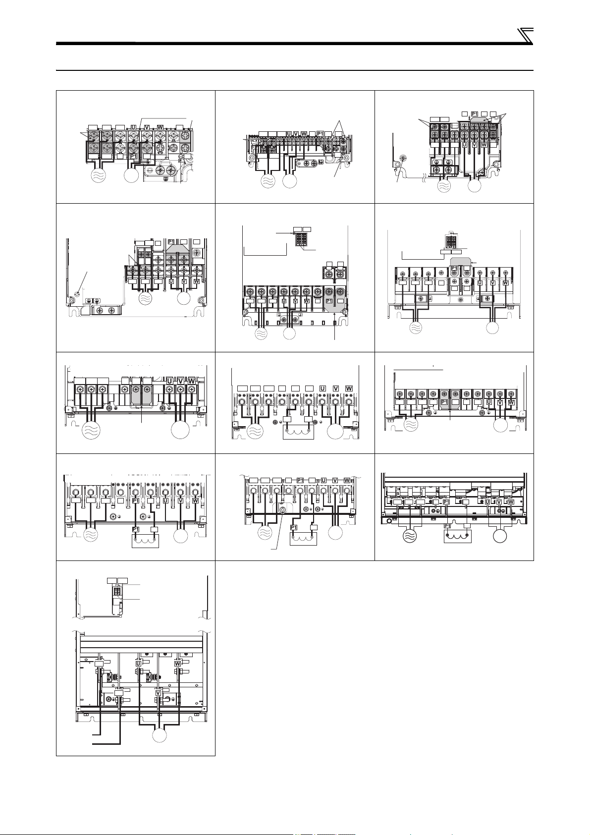
2.2 Main circuit terminal
2.2.1 Terminal layout and wiring
FR-F820-00046(0.75K), 00077(1.5K) FR-F820-00105(2.2K) to 00250(5.5K)
FR-F840-00023(0.75K) to 00126(5.5K)
FR-F820-00340(7.5K), 00490(11K)
FR-F840-00170(7.5K), 00250(11K)
FR-F820-00630(15K)
FR-F840-00310(15K), 00380(18.5K)
FR-F820-01870(45K), 02330(55K)
R/L1 S/L2 T/L3
R1/L11 S1/L21
P/+
PR
N/-
PX
M
FR-F820-00770(18.5K) to 01250(30K)
FR-F840-00470(22K), 00620(30K)
*1
FR-F820-03160(75K)
*1
FR-F820-01540(37K)
FR-F840-00770(37K)
FR-F840-00930(45K) to 01800(75K)
*2
*1, *3
FR-F840-02160(90K), 02600(110K)
FR-F842-07700(355K) to 12120(560K)
For footnotes *1 to *4 refer to next page.
12
*1
FR-F820-03800(90K), 04750(110K)
FR-F840-03250(132K) to 04810(220K)
*1
FR-F840-05470(250K) to 06830(315K)
*1
*1
*4
WIRING
Charge lamp
Jumper
*1
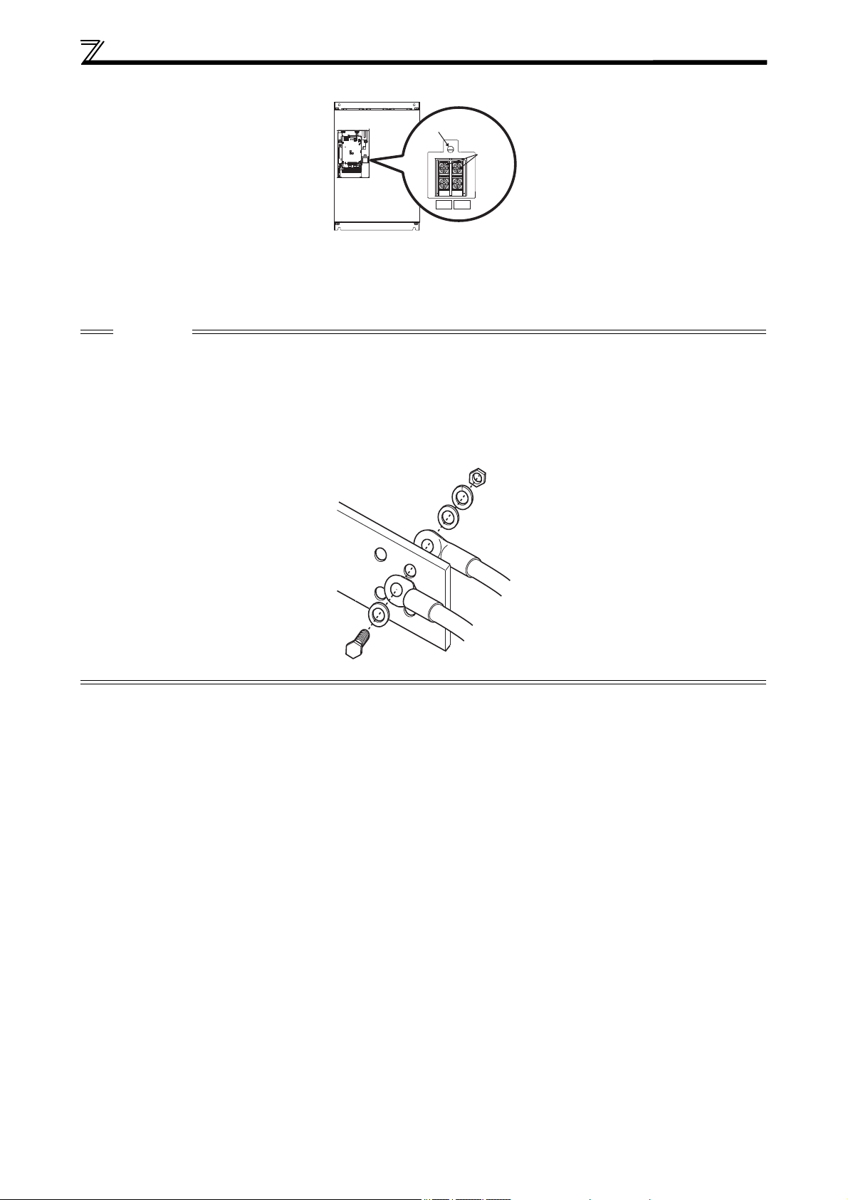
The following diagram shows the positions of R1/L11, S1/L21, and the charge lamp.
R1/L11 S1/L21
*2
The terminals P3 and PR of the FR-F820-01540(37K) are not equipped with screws. Do not connect anything to these.
*3
For the FR-F840-01800(75K), a jumper is not installed across the terminals P1 and P/+. Always connect a DC reactor (FR-HEL),
which is available as an option, across the terminals P1 and P/+.
*4
For terminal layout and wiring of the converter unit (FR-CC2) refer to the FR-CC2 Instruction Manual.
CAUTION
The power supply cables must be connected to R/L1, S/L2, T/L3. Never connect the power cable to the U, V, W, of the
inverter. Doing so will damage the inverter. (Phase sequence needs not to be matched.)
Connect the motor to U, V, W. At this time turning on the forward rotation switch (signal) rotates the motor in the
clockwise direction when viewed from the motor shaft. (The phase sequence must be matched.)
The charge lamp will turn ON when the power is supplied to the main circuit.
When wiring the inverter main circuit conductor of the FR-F840-05470(250K) or higher, tighten a nut from the right side
of the conductor. When wiring two wires, place wires on both sides of the conductor (refer to the drawing). For wiring,
use bolts (nuts) provided with the inverter.
For wiring the main circuit conductor of the converter unit (FR-CC2) refer to the FR-CC2 Instruction Manual.
13
WIRING
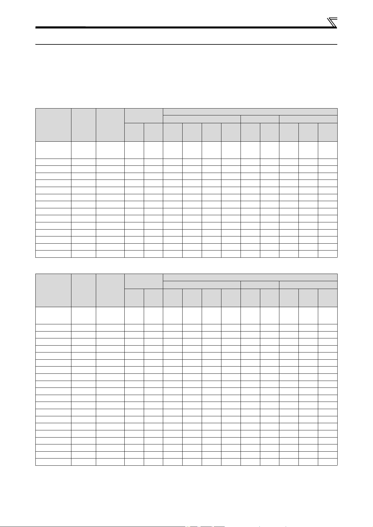
2.3 Wiring fundamentals
2.3.1 Cable size
Select the recommended cable size to ensure that the voltage drop will be 2% max.
If the wiring distance is long between the inverter and motor, the main circuit cable voltage drop will cause the motor
torque to decrease especially at the output of a low frequency.
The following tables indicate a selection example for the wiring length of 20m.
LD rating (Pr. 570 "Multiple rating setting" = "1")
200V class, FR-F820 (when input power supply is 220V)
Crimping
Applicable
inverter type
FR-F820-
00046(0.75K)
to
00105(2.2K)
00167(3.7K) M4 1.5 5.5-4 5.5-4 3.5 3.5 3.5 3.5 12 12 4 4 4
00250(5.5K) M4 1.5 5.5-4 5.5-4 5.5 5.5 5.5 5.5 10 10 6 6 6
00340(7.5K) M5 2.5 8-5 5.5-5 8 5.5 14 5.5 6 10 16 6 16
00490(11K) M5 2.5 14-5 14-5 14 14 14 8 6 6 16 16 16
00630(15K) M5 2.5 22-5 22-5 22 22 22 14 4 4 25 25 16
00770(18.5K) M6 4.4 38-6 22-6 38 22 38 14 2 4 35 25 25
00930(22K) M8(M6) 7.8 38-8 38-8 38 38 38 22 2 2 35 35 25
01250(30K) M8(M6) 7.8 60-8 60-8 60 60 60 22 1/0 1/0 50 50 25
01540(37K) M8(M6) 7.8 80-8 60-8 80 80 80 22 3/0 1/0 70 70 35
01870(45K) M10(M8) 14.7 100-10 100-10 100 100 100 38 4/0 4/0 95 95 50
02330(55K) M10(M8) 14.7 100-10 100-10 100 100 100 38 4/0 4/0 95 95 50
03160(75K) M12(M8) 24.5 150-12 150-12 125 125 150 38 250 250 — — —
03800(90K) M12(M8) 24.5 150-12 150-12 150 150 2×100 38 2×4/0 2×4/0 — — —
04750(110K) M12(M8) 24.5 100-12 100-12 150 150 2×100 38 2×4/0 2×4/0 — — —
Ter minal
screw
size
Tightening
torque
*4
[Nm]
M4 1.5 2-4 2-4 2 2 2 2 14 14 2.5 2.5 2.5
Ter minal
R/L1,
S/L2,
T/L3
U, V, W
HIV, etc. [mm²]
R/L1,
S/L2,
T/L3
U, V, W P/+, P1
*1
Earth
cable
gauge
Cable sizes
AWG/MCM
R/L1,
S/L2,
T/L3
*2
U, V, W
PVC, etc. [mm²]
R/L1,
U, V, W
S/L2,
T/L3
*3
Earth
cable
gauge
400V class, FR-F840 (when input power supply is 440V)
Crimping
Applicable
inverter type
FR-F840-
00023(0.75K)
to
00083(3.7K)
00126(5.5K) M4 1.5 2-4 2-4 2 2 3.5 3.5 12 14 2.5 2.5 4
00170(7.5K) M4 1.5 5.5-4 5.5-4 3.5 3.5 3.5 3.5 12 12 4 4 4
00250(11K) M4 1.5 5.5-4 5.5-4 5.5 5.5 5.5 5.5 10 10 6 6 10
00310(15K) M5 2.5 8-5 5.5-5 8 5.5 8 5.5 8 10 10 6 10
00380(18.5K) M5 2.5 14-5 8-5 14 8 14 8 6 8 16 10 16
00470(22K) M6 4.4 14-6 14-6 14 14 22 14 6 6 16 16 16
00620(30K) M6 4.4 22-6 22-6 22 22 22 14 4 4 25 25 16
00770(37K) M6 4.4 22-6 22-6 22 22 22 14 4 4 25 25 16
00930(45K) M8 7.8 38-8 38-8 38 38 38 22 1 2 50 50 25
01160(55K) M8 7.8 60-8 60-8 60 60 60 22 1/0 1/0 50 50 25
01800(75K) M8 7.8 60-8 60-8 60 60 60 22 1/0 1/0 50 50 25
02160(90K) M10 14.7 60-10 60-10 60 60 60 22 1/0 1/0 50 50 25
02600(110K) M10 14.7 80-10 80-10 80 80 80 22 3/0 3/0 70 70 35
03250(132K) M10(M12) 14.7 100-10 100-10 100 100 100 38 4/0 4/0 95 95 50
03610(160K) M10(M12) 14.7 150-10 150-10 125 125 100 38 250 250 120 120 70
04320(185K) M12(M10) 24.5 150-12 150-12 150 150 150 38 300 300 150 150 95
04810(220K) M12(M10) 24.5 100-12 100-12 2×100 2×100 2×100 60 2×4/0 2×4/0 2×95 2×95 95
05470(250K) M12(M10) 46 100-12 100-12 2×100 2×100 2×100 60 2×4/0 2×4/0 2×952×95 95
06100(280K) M12(M10) 46 150-12 150-12 2×125 2×125 2×125 60 2×250 2×250 2×120 2×120 120
06830(315K) M12(M10) 46 150-12 150-12 2×150 2×150 2×125 60 2×300 2×300 2×150 2×150 150
Ter minal
screw
size
Tightening
torque
*4
[Nm]
M4 1.5 2-4 2-4 2 2 2 2 14 14 2.5 2.5 2.5
terminal
R/L1,
S/L2,
T/L3
U, V, W
HIV, etc. [mm²]
R/L1,
S/L2,
T/L3
U, V, W P/+, P1
*1
Earth
cable
gauge
Cable sizes
AWG/MCM
R/L1,
S/L2,
T/L3
*2
U, V, W
PVC, etc. [mm²]
R/L1,
U, V, W
S/L2,
T/L3
*3
Earth
cable
gauge
For footnotes *1 to *4 refer to next page.
14
 Loading...