

Mitsubishi FR-F820-00077, FR-F820-00630, FR-F820-00340, FR-F820-00490, FR-F820-00770 Instruction Manual
...
INVERTER
FR-F800
INSTRUCTION MANUAL (DETAILED)
Inverter for fans and pumps
FR-F820-00046(0.75K) to 04750(110K)
FR-F840-00023(0.75K) to 06830(315K)
FR-F842-07700(355K) to 12120(560K)
FR-F846-00023(0.75K) to 03610(160K)

Safety instructions. . . . . . . . . . . . . . . . . . . . . . . . . . . . . . . . . . . . . . . . . . . . . . . . . . . . . . . . . . . . . . . . . 8
Chapter 1 INTRODUCTION . . . . . . . . . . . . . . . . . . . . . . . . . . . . . . 16
1.1 Product checking and accessories . . . . . . . . . . . . . . . . . . . . . . . . . . . . . . . . . . . . . . . . . . . . . 17
1.2 Component names . . . . . . . . . . . . . . . . . . . . . . . . . . . . . . . . . . . . . . . . . . . . . . . . . . . . . . . . . 19
1.3 Operation steps . . . . . . . . . . . . . . . . . . . . . . . . . . . . . . . . . . . . . . . . . . . . . . . . . . . . . . . . . . . . 21
1.4 About the related manuals. . . . . . . . . . . . . . . . . . . . . . . . . . . . . . . . . . . . . . . . . . . . . . . . . . . . 22
Chapter 2 INSTALLATION AND WIRING . . . . . . . . . . . . . . . . . . . 24
2.1 Peripheral devices . . . . . . . . . . . . . . . . . . . . . . . . . . . . . . . . . . . . . . . . . . . . . . . . . . . . . . . . . . 24
2.1.1 Inverter and peripheral devices. . . . . . . . . . . . . . . . . . . . . . . . . . . . . . . . . . . . . . . . . . . . . . . . . . . . . . . . . . . . . . . . . . . . . . 24
2.1.2 Peripheral devices. . . . . . . . . . . . . . . . . . . . . . . . . . . . . . . . . . . . . . . . . . . . . . . . . . . . . . . . . . . . . . . . . . . . . . . . . . . . . . . . 26
2.2 Removal and reinstallation of the operation panel or the front covers. . . . . . . . . . . . . . . . . . . 30
2.3 Installation of the inverter and enclosure design . . . . . . . . . . . . . . . . . . . . . . . . . . . . . . . . . . . 34
2.3.1 Inverter installation environment . . . . . . . . . . . . . . . . . . . . . . . . . . . . . . . . . . . . . . . . . . . . . . . . . . . . . . . . . . . . . . . . . . . . . 34
2.3.2 Amount of heat generated by the inverter. . . . . . . . . . . . . . . . . . . . . . . . . . . . . . . . . . . . . . . . . . . . . . . . . . . . . . . . . . . . . . 37
2.3.3 Cooling system types for inverter enclosure . . . . . . . . . . . . . . . . . . . . . . . . . . . . . . . . . . . . . . . . . . . . . . . . . . . . . . . . . . . . 38
2.3.4 Inverter installation . . . . . . . . . . . . . . . . . . . . . . . . . . . . . . . . . . . . . . . . . . . . . . . . . . . . . . . . . . . . . . . . . . . . . . . . . . . . . . . 39
2.3.5 Protruding the heat sink through a panel . . . . . . . . . . . . . . . . . . . . . . . . . . . . . . . . . . . . . . . . . . . . . . . . . . . . . . . . . . . . . . 41
2.4 Terminal connection diagrams. . . . . . . . . . . . . . . . . . . . . . . . . . . . . . . . . . . . . . . . . . . . . . . . . 43
2.5 Main circuit terminals . . . . . . . . . . . . . . . . . . . . . . . . . . . . . . . . . . . . . . . . . . . . . . . . . . . . . . . . 47
2.5.1 Details on the main circuit terminals . . . . . . . . . . . . . . . . . . . . . . . . . . . . . . . . . . . . . . . . . . . . . . . . . . . . . . . . . . . . . . . . . . 47
2.5.2 Main circuit terminal layout and wiring to power supply and motor . . . . . . . . . . . . . . . . . . . . . . . . . . . . . . . . . . . . . . . . . . . 48
2.5.3 Applicable cables and wiring length . . . . . . . . . . . . . . . . . . . . . . . . . . . . . . . . . . . . . . . . . . . . . . . . . . . . . . . . . . . . . . . . . . 50
2.5.4 Earthing (grounding) precautions . . . . . . . . . . . . . . . . . . . . . . . . . . . . . . . . . . . . . . . . . . . . . . . . . . . . . . . . . . . . . . . . . . . . 57
CONTENTS
2.6 Control circuit. . . . . . . . . . . . . . . . . . . . . . . . . . . . . . . . . . . . . . . . . . . . . . . . . . . . . . . . . . . . . . 58
2.6.1 Details on the control circuit terminals . . . . . . . . . . . . . . . . . . . . . . . . . . . . . . . . . . . . . . . . . . . . . . . . . . . . . . . . . . . . . . . . 58
2.6.2 Control logic (sink/source) change . . . . . . . . . . . . . . . . . . . . . . . . . . . . . . . . . . . . . . . . . . . . . . . . . . . . . . . . . . . . . . . . . . . 62
2.6.3 Wiring of control circuit . . . . . . . . . . . . . . . . . . . . . . . . . . . . . . . . . . . . . . . . . . . . . . . . . . . . . . . . . . . . . . . . . . . . . . . . . . . . 63
2.6.4 Wiring precautions . . . . . . . . . . . . . . . . . . . . . . . . . . . . . . . . . . . . . . . . . . . . . . . . . . . . . . . . . . . . . . . . . . . . . . . . . . . . . . . 66
2.6.5 When using separate power supplies for the control circuit and the main circuit . . . . . . . . . . . . . . . . . . . . . . . . . . . . . . . . 66
2.6.6 When supplying 24 V external power to the control circuit . . . . . . . . . . . . . . . . . . . . . . . . . . . . . . . . . . . . . . . . . . . . . . . . . 69
2.6.7 Safety stop function. . . . . . . . . . . . . . . . . . . . . . . . . . . . . . . . . . . . . . . . . . . . . . . . . . . . . . . . . . . . . . . . . . . . . . . . . . . . . . . 70
2.7 Communication connectors and terminals. . . . . . . . . . . . . . . . . . . . . . . . . . . . . . . . . . . . . . . . 73
2.7.1 PU connector . . . . . . . . . . . . . . . . . . . . . . . . . . . . . . . . . . . . . . . . . . . . . . . . . . . . . . . . . . . . . . . . . . . . . . . . . . . . . . . . . . . 73
2.7.2 USB connector . . . . . . . . . . . . . . . . . . . . . . . . . . . . . . . . . . . . . . . . . . . . . . . . . . . . . . . . . . . . . . . . . . . . . . . . . . . . . . . . . . 74
2.7.3 RS-485 terminal block. . . . . . . . . . . . . . . . . . . . . . . . . . . . . . . . . . . . . . . . . . . . . . . . . . . . . . . . . . . . . . . . . . . . . . . . . . . . . 75
2.8 Connection of stand-alone option units . . . . . . . . . . . . . . . . . . . . . . . . . . . . . . . . . . . . . . . . . . 76
2.8.1 Connection of the brake unit (FR-BU2) . . . . . . . . . . . . . . . . . . . . . . . . . . . . . . . . . . . . . . . . . . . . . . . . . . . . . . . . . . . . . . . . 76
1

2.8.2 Connection of the brake unit (FR-BU). . . . . . . . . . . . . . . . . . . . . . . . . . . . . . . . . . . . . . . . . . . . . . . . . . . . . . . . . . . . . . . . . 78
2.8.3 Connection of the brake unit (BU type). . . . . . . . . . . . . . . . . . . . . . . . . . . . . . . . . . . . . . . . . . . . . . . . . . . . . . . . . . . . . . . . 78
2.8.4 Connection of the high power factor converter (FR-HC2). . . . . . . . . . . . . . . . . . . . . . . . . . . . . . . . . . . . . . . . . . . . . . . . . . 79
2.8.5 Connection of the power regeneration common converter (FR-CV). . . . . . . . . . . . . . . . . . . . . . . . . . . . . . . . . . . . . . . . . . 80
2.8.6 Connection of the power regeneration converter (MT-RC). . . . . . . . . . . . . . . . . . . . . . . . . . . . . . . . . . . . . . . . . . . . . . . . . 81
2.8.7 Connection of the DC reactor (FR-HEL) . . . . . . . . . . . . . . . . . . . . . . . . . . . . . . . . . . . . . . . . . . . . . . . . . . . . . . . . . . . . . . . 81
Chapter 3 PRECAUTIONS FOR USE OF THE INVERTER . . . . . 84
3.1 Electro-magnetic interference (EMI) and leakage currents . . . . . . . . . . . . . . . . . . . . . . . . . . .84
3.1.1 Leakage currents and countermeasures. . . . . . . . . . . . . . . . . . . . . . . . . . . . . . . . . . . . . . . . . . . . . . . . . . . . . . . . . . . . . . . 84
3.1.2 Techniques and measures for electromagnetic compatibility (EMC) . . . . . . . . . . . . . . . . . . . . . . . . . . . . . . . . . . . . . . . . . 86
3.1.3 Built-in EMC filter . . . . . . . . . . . . . . . . . . . . . . . . . . . . . . . . . . . . . . . . . . . . . . . . . . . . . . . . . . . . . . . . . . . . . . . . . . . . . . . . 88
3.2 Power supply harmonics . . . . . . . . . . . . . . . . . . . . . . . . . . . . . . . . . . . . . . . . . . . . . . . . . . . . .91
3.2.1 Power supply harmonics . . . . . . . . . . . . . . . . . . . . . . . . . . . . . . . . . . . . . . . . . . . . . . . . . . . . . . . . . . . . . . . . . . . . . . . . . . . 91
3.2.2 Harmonic suppression guidelines in Japan. . . . . . . . . . . . . . . . . . . . . . . . . . . . . . . . . . . . . . . . . . . . . . . . . . . . . . . . . . . . . 91
3.3 Installation of a reactor . . . . . . . . . . . . . . . . . . . . . . . . . . . . . . . . . . . . . . . . . . . . . . . . . . . . . . .95
3.4 Power shutdown and magnetic contactor (MC) . . . . . . . . . . . . . . . . . . . . . . . . . . . . . . . . . . . .96
3.5 Countermeasures against deterioration of the 400 V class motor insulation . . . . . . . . . . . . . . 98
3.6 Checklist before starting operation. . . . . . . . . . . . . . . . . . . . . . . . . . . . . . . . . . . . . . . . . . . . . .99
3.7 Failsafe system which uses the inverter. . . . . . . . . . . . . . . . . . . . . . . . . . . . . . . . . . . . . . . . .102
Chapter 4 BASIC OPERATION . . . . . . . . . . . . . . . . . . . . . . . . . 106
4.1 Operation panel (FR-DU08) . . . . . . . . . . . . . . . . . . . . . . . . . . . . . . . . . . . . . . . . . . . . . . . . . .106
4.1.1 Components of the operation panel (FR-DU08) . . . . . . . . . . . . . . . . . . . . . . . . . . . . . . . . . . . . . . . . . . . . . . . . . . . . . . . . 106
4.1.2 Basic operation of the operation panel . . . . . . . . . . . . . . . . . . . . . . . . . . . . . . . . . . . . . . . . . . . . . . . . . . . . . . . . . . . . . . . 108
4.1.3 Digital characters and their corresponding printed equivalents . . . . . . . . . . . . . . . . . . . . . . . . . . . . . . . . . . . . . . . . . . . . 109
4.1.4 Changing the parameter setting value . . . . . . . . . . . . . . . . . . . . . . . . . . . . . . . . . . . . . . . . . . . . . . . . . . . . . . . . . . . . . . . 110
4.2 Monitoring the inverter . . . . . . . . . . . . . . . . . . . . . . . . . . . . . . . . . . . . . . . . . . . . . . . . . . . . . .111
4.2.1 Monitoring of output current and output voltage . . . . . . . . . . . . . . . . . . . . . . . . . . . . . . . . . . . . . . . . . . . . . . . . . . . . . . . . 111
4.2.2 First priority monitor screen. . . . . . . . . . . . . . . . . . . . . . . . . . . . . . . . . . . . . . . . . . . . . . . . . . . . . . . . . . . . . . . . . . . . . . . . 111
4.2.3 Displaying the set frequency. . . . . . . . . . . . . . . . . . . . . . . . . . . . . . . . . . . . . . . . . . . . . . . . . . . . . . . . . . . . . . . . . . . . . . . 111
4.3 Easy setting of the inverter operation mode. . . . . . . . . . . . . . . . . . . . . . . . . . . . . . . . . . . . . .112
4.4 Frequently-used parameters (simple mode parameters) . . . . . . . . . . . . . . . . . . . . . . . . . . . . 114
4.4.1 Simple mode parameter list . . . . . . . . . . . . . . . . . . . . . . . . . . . . . . . . . . . . . . . . . . . . . . . . . . . . . . . . . . . . . . . . . . . . . . . 114
4.5 Basic operation procedure (PU operation) . . . . . . . . . . . . . . . . . . . . . . . . . . . . . . . . . . . . . . .116
4.5.1 Setting the frequency on the operation panel (example: operating at 30 Hz) . . . . . . . . . . . . . . . . . . . . . . . . . . . . . . . . . . 116
4.5.2 Perform PU operation using the setting dial like a potentiometer . . . . . . . . . . . . . . . . . . . . . . . . . . . . . . . . . . . . . . . . . . . 117
4.5.3 Setting the frequency with switches (multi-speed setting) . . . . . . . . . . . . . . . . . . . . . . . . . . . . . . . . . . . . . . . . . . . . . . . . 118
4.5.4 Setting the frequency using an analog signal (voltage input) . . . . . . . . . . . . . . . . . . . . . . . . . . . . . . . . . . . . . . . . . . . . . . 119
4.5.5 Setting the frequency using an analog signal (current input) . . . . . . . . . . . . . . . . . . . . . . . . . . . . . . . . . . . . . . . . . . . . . . 120
2

4.6 Basic operation procedure (External operation) . . . . . . . . . . . . . . . . . . . . . . . . . . . . . . . . . . 122
4.6.1 Setting the frequency on the operation panel . . . . . . . . . . . . . . . . . . . . . . . . . . . . . . . . . . . . . . . . . . . . . . . . . . . . . . . . . . 122
4.6.2 Setting the frequency and giving a start command with switches (multi-speed setting) (Pr.4 to Pr.6) . . . . . . . . . . . . . . . 123
4.6.3 Setting the frequency using an analog signal (voltage input) . . . . . . . . . . . . . . . . . . . . . . . . . . . . . . . . . . . . . . . . . . . . . . 124
4.6.4 Changing the frequency (60 Hz, initial value) at the maximum voltage input (5 V, initial value). . . . . . . . . . . . . . . . . . . . 126
4.6.5 Setting the frequency using an analog signal (current input) . . . . . . . . . . . . . . . . . . . . . . . . . . . . . . . . . . . . . . . . . . . . . . 127
4.6.6 Changing the frequency (60 Hz, initial value) at the maximum current input (at 20 mA, initial value) . . . . . . . . . . . . . . . 128
4.7 Basic operation procedure (JOG operation) . . . . . . . . . . . . . . . . . . . . . . . . . . . . . . . . . . . . . 129
4.7.1 Giving a start command by using external signals for JOG operation . . . . . . . . . . . . . . . . . . . . . . . . . . . . . . . . . . . . . . . 129
4.7.2 Giving a start command from the operation panel for JOG operation. . . . . . . . . . . . . . . . . . . . . . . . . . . . . . . . . . . . . . . . 130
Chapter 5 PARAMETERS . . . . . . . . . . . . . . . . . . . . . . . . . . . . . . 132
5.1 Parameter list. . . . . . . . . . . . . . . . . . . . . . . . . . . . . . . . . . . . . . . . . . . . . . . . . . . . . . . . . . . . . 132
5.1.1 Parameter list (by parameter number) . . . . . . . . . . . . . . . . . . . . . . . . . . . . . . . . . . . . . . . . . . . . . . . . . . . . . . . . . . . . . . . 132
5.1.2 Use of a function group number for the identification of parameters . . . . . . . . . . . . . . . . . . . . . . . . . . . . . . . . . . . . . . . . 156
5.1.3 Parameter list (by function group number) . . . . . . . . . . . . . . . . . . . . . . . . . . . . . . . . . . . . . . . . . . . . . . . . . . . . . . . . . . . . 158
5.2 Control method . . . . . . . . . . . . . . . . . . . . . . . . . . . . . . . . . . . . . . . . . . . . . . . . . . . . . . . . . . . 167
5.2.1 Changing the control method and mode. . . . . . . . . . . . . . . . . . . . . . . . . . . . . . . . . . . . . . . . . . . . . . . . . . . . . . . . . . . . . . 169
5.2.2 Selecting the Advanced magnetic flux vector control . . . . . . . . . . . . . . . . . . . . . . . . . . . . . . . . . . . . . . . . . . . . . . . . . . . . 172
5.2.3 Selecting the PM motor control . . . . . . . . . . . . . . . . . . . . . . . . . . . . . . . . . . . . . . . . . . . . . . . . . . . . . . . . . . . . . . . . . . . . . 174
CONTENTS
5.3 Speed control under PM motor control . . . . . . . . . . . . . . . . . . . . . . . . . . . . . . . . . . . . . . . . . 180
5.3.1 Setting procedure of PM motor control . . . . . . . . . . . . . . . . . . . . . . . . . . . . . . . . . . . . . . . . . . . . . . . . . . . . . . . . . . . . . . . 180
5.3.2 Performing high-accuracy, fast-response control (gain adjustment for PM motor control) . . . . . . . . . . . . . . . . . . . . . . . . 182
5.3.3 Troubleshooting in the speed control . . . . . . . . . . . . . . . . . . . . . . . . . . . . . . . . . . . . . . . . . . . . . . . . . . . . . . . . . . . . . . . . 184
5.3.4 Torque detection filter . . . . . . . . . . . . . . . . . . . . . . . . . . . . . . . . . . . . . . . . . . . . . . . . . . . . . . . . . . . . . . . . . . . . . . . . . . . . 185
5.4 (E) Environment setting parameters . . . . . . . . . . . . . . . . . . . . . . . . . . . . . . . . . . . . . . . . . . . 186
5.4.1 Real time clock function . . . . . . . . . . . . . . . . . . . . . . . . . . . . . . . . . . . . . . . . . . . . . . . . . . . . . . . . . . . . . . . . . . . . . . . . . . 187
5.4.2 Reset selection / disconnected PU detection / PU stop selection . . . . . . . . . . . . . . . . . . . . . . . . . . . . . . . . . . . . . . . . . . . 188
5.4.3 PU display language selection . . . . . . . . . . . . . . . . . . . . . . . . . . . . . . . . . . . . . . . . . . . . . . . . . . . . . . . . . . . . . . . . . . . . . 191
5.4.4 Beep control . . . . . . . . . . . . . . . . . . . . . . . . . . . . . . . . . . . . . . . . . . . . . . . . . . . . . . . . . . . . . . . . . . . . . . . . . . . . . . . . . . . 191
5.4.5 PU contrast adjustment. . . . . . . . . . . . . . . . . . . . . . . . . . . . . . . . . . . . . . . . . . . . . . . . . . . . . . . . . . . . . . . . . . . . . . . . . . . 191
5.4.6 Display-off setting . . . . . . . . . . . . . . . . . . . . . . . . . . . . . . . . . . . . . . . . . . . . . . . . . . . . . . . . . . . . . . . . . . . . . . . . . . . . . . . 191
5.4.7 Direct setting . . . . . . . . . . . . . . . . . . . . . . . . . . . . . . . . . . . . . . . . . . . . . . . . . . . . . . . . . . . . . . . . . . . . . . . . . . . . . . . . . . . 192
5.4.8 Resetting USB host errors . . . . . . . . . . . . . . . . . . . . . . . . . . . . . . . . . . . . . . . . . . . . . . . . . . . . . . . . . . . . . . . . . . . . . . . . 192
5.4.9 Easy frequency setting (Volume-knob-like setting) and key lock function selection . . . . . . . . . . . . . . . . . . . . . . . . . . . . . 192
5.4.10 Frequency change increment amount setting. . . . . . . . . . . . . . . . . . . . . . . . . . . . . . . . . . . . . . . . . . . . . . . . . . . . . . . . . . 193
5.4.11 Multiple rating setting . . . . . . . . . . . . . . . . . . . . . . . . . . . . . . . . . . . . . . . . . . . . . . . . . . . . . . . . . . . . . . . . . . . . . . . . . . . . 194
5.4.12 Using the power supply exceeding 480 VAC . . . . . . . . . . . . . . . . . . . . . . . . . . . . . . . . . . . . . . . . . . . . . . . . . . . . . . . . . . 195
5.4.13 Parameter write selection . . . . . . . . . . . . . . . . . . . . . . . . . . . . . . . . . . . . . . . . . . . . . . . . . . . . . . . . . . . . . . . . . . . . . . . . . 196
5.4.14 Password . . . . . . . . . . . . . . . . . . . . . . . . . . . . . . . . . . . . . . . . . . . . . . . . . . . . . . . . . . . . . . . . . . . . . . . . . . . . . . . . . . . . . 198
5.4.15 Free parameter . . . . . . . . . . . . . . . . . . . . . . . . . . . . . . . . . . . . . . . . . . . . . . . . . . . . . . . . . . . . . . . . . . . . . . . . . . . . . . . . . 200
5.4.16 Setting multiple parameters by batch . . . . . . . . . . . . . . . . . . . . . . . . . . . . . . . . . . . . . . . . . . . . . . . . . . . . . . . . . . . . . . . . 200
5.4.17 Extended parameter display and user group function. . . . . . . . . . . . . . . . . . . . . . . . . . . . . . . . . . . . . . . . . . . . . . . . . . . . 204
5.4.18 PWM carrier frequency and Soft-PWM control . . . . . . . . . . . . . . . . . . . . . . . . . . . . . . . . . . . . . . . . . . . . . . . . . . . . . . . . . 207
5.4.19 Inverter parts life display . . . . . . . . . . . . . . . . . . . . . . . . . . . . . . . . . . . . . . . . . . . . . . . . . . . . . . . . . . . . . . . . . . . . . . . . . . 208
5.4.20 Maintenance timer alarm. . . . . . . . . . . . . . . . . . . . . . . . . . . . . . . . . . . . . . . . . . . . . . . . . . . . . . . . . . . . . . . . . . . . . . . . . . 212
5.4.21 Current average value monitor signal . . . . . . . . . . . . . . . . . . . . . . . . . . . . . . . . . . . . . . . . . . . . . . . . . . . . . . . . . . . . . . . . 213
5.5 (F) Setting of acceleration/deceleration time and acceleration/deceleration pattern. . . . . . . 216
5.5.1 Setting the acceleration and deceleration time. . . . . . . . . . . . . . . . . . . . . . . . . . . . . . . . . . . . . . . . . . . . . . . . . . . . . . . . . 216
5.5.2 Acceleration/deceleration pattern . . . . . . . . . . . . . . . . . . . . . . . . . . . . . . . . . . . . . . . . . . . . . . . . . . . . . . . . . . . . . . . . . . . 219
5.5.3 Remote setting function . . . . . . . . . . . . . . . . . . . . . . . . . . . . . . . . . . . . . . . . . . . . . . . . . . . . . . . . . . . . . . . . . . . . . . . . . . 222
5.5.4 Starting frequency and start-time hold function. . . . . . . . . . . . . . . . . . . . . . . . . . . . . . . . . . . . . . . . . . . . . . . . . . . . . . . . . 225
5.5.5 Minimum motor speed frequency at the motor start up. . . . . . . . . . . . . . . . . . . . . . . . . . . . . . . . . . . . . . . . . . . . . . . . . . . 226
3

5.6 (D) Operation command and frequency command . . . . . . . . . . . . . . . . . . . . . . . . . . . . . . . . 228
5.6.1 Operation mode selection . . . . . . . . . . . . . . . . . . . . . . . . . . . . . . . . . . . . . . . . . . . . . . . . . . . . . . . . . . . . . . . . . . . . . . . . . 228
5.6.2 Startup of the inverter in Network operation mode at power-ON . . . . . . . . . . . . . . . . . . . . . . . . . . . . . . . . . . . . . . . . . . . 237
5.6.3 Start command source and frequency command source during communication operation . . . . . . . . . . . . . . . . . . . . . . . 239
5.6.4 Reverse rotation prevention selection . . . . . . . . . . . . . . . . . . . . . . . . . . . . . . . . . . . . . . . . . . . . . . . . . . . . . . . . . . . . . . . . 245
5.6.5 Frequency setting using pulse train input . . . . . . . . . . . . . . . . . . . . . . . . . . . . . . . . . . . . . . . . . . . . . . . . . . . . . . . . . . . . . 245
5.6.6 JOG operation . . . . . . . . . . . . . . . . . . . . . . . . . . . . . . . . . . . . . . . . . . . . . . . . . . . . . . . . . . . . . . . . . . . . . . . . . . . . . . . . . . 248
5.6.7 Operation by multi-speed setting . . . . . . . . . . . . . . . . . . . . . . . . . . . . . . . . . . . . . . . . . . . . . . . . . . . . . . . . . . . . . . . . . . . 249
5.7 (H) Protective function parameter . . . . . . . . . . . . . . . . . . . . . . . . . . . . . . . . . . . . . . . . . . . . .252
5.7.1 Motor overheat protection (electronic thermal O/L relay) . . . . . . . . . . . . . . . . . . . . . . . . . . . . . . . . . . . . . . . . . . . . . . . . . 252
5.7.2 Cooling fan operation selection. . . . . . . . . . . . . . . . . . . . . . . . . . . . . . . . . . . . . . . . . . . . . . . . . . . . . . . . . . . . . . . . . . . . . 258
5.7.3 Earth (ground) fault detection at start . . . . . . . . . . . . . . . . . . . . . . . . . . . . . . . . . . . . . . . . . . . . . . . . . . . . . . . . . . . . . . . . 259
5.7.4 Varying the activation level of the undervoltage protective function . . . . . . . . . . . . . . . . . . . . . . . . . . . . . . . . . . . . . . . . . 260
5.7.5 Initiating a protective function . . . . . . . . . . . . . . . . . . . . . . . . . . . . . . . . . . . . . . . . . . . . . . . . . . . . . . . . . . . . . . . . . . . . . . 260
5.7.6 I/O phase loss protection selection . . . . . . . . . . . . . . . . . . . . . . . . . . . . . . . . . . . . . . . . . . . . . . . . . . . . . . . . . . . . . . . . . . 260
5.7.7 Retry function . . . . . . . . . . . . . . . . . . . . . . . . . . . . . . . . . . . . . . . . . . . . . . . . . . . . . . . . . . . . . . . . . . . . . . . . . . . . . . . . . . 261
5.7.8 Emergency drive . . . . . . . . . . . . . . . . . . . . . . . . . . . . . . . . . . . . . . . . . . . . . . . . . . . . . . . . . . . . . . . . . . . . . . . . . . . . . . . . 263
5.7.9 Limiting the output frequency (maximum/minimum frequency). . . . . . . . . . . . . . . . . . . . . . . . . . . . . . . . . . . . . . . . . . . . . 271
5.7.10 Avoiding machine resonance points (frequency jump) . . . . . . . . . . . . . . . . . . . . . . . . . . . . . . . . . . . . . . . . . . . . . . . . . . . 272
5.7.11 Stall prevention operation . . . . . . . . . . . . . . . . . . . . . . . . . . . . . . . . . . . . . . . . . . . . . . . . . . . . . . . . . . . . . . . . . . . . . . . . . 273
5.7.12 Load characteristics fault detection. . . . . . . . . . . . . . . . . . . . . . . . . . . . . . . . . . . . . . . . . . . . . . . . . . . . . . . . . . . . . . . . . . 281
5.7.13 Motor overspeeding detection. . . . . . . . . . . . . . . . . . . . . . . . . . . . . . . . . . . . . . . . . . . . . . . . . . . . . . . . . . . . . . . . . . . . . . 285
5.8 (M) Item and output signal for monitoring. . . . . . . . . . . . . . . . . . . . . . . . . . . . . . . . . . . . . . . .286
5.8.1 Speed indication and its setting change to rotations per minute. . . . . . . . . . . . . . . . . . . . . . . . . . . . . . . . . . . . . . . . . . . . 286
5.8.2 Monitor item selection on operation panel or via communication . . . . . . . . . . . . . . . . . . . . . . . . . . . . . . . . . . . . . . . . . . . 288
5.8.3 Monitor display selection for terminals FM/CA and AM . . . . . . . . . . . . . . . . . . . . . . . . . . . . . . . . . . . . . . . . . . . . . . . . . . 297
5.8.4 Adjustment of terminal FM/CA and terminal AM . . . . . . . . . . . . . . . . . . . . . . . . . . . . . . . . . . . . . . . . . . . . . . . . . . . . . . . . 302
5.8.5 Energy saving monitoring . . . . . . . . . . . . . . . . . . . . . . . . . . . . . . . . . . . . . . . . . . . . . . . . . . . . . . . . . . . . . . . . . . . . . . . . . 306
5.8.6 Output terminal function selection . . . . . . . . . . . . . . . . . . . . . . . . . . . . . . . . . . . . . . . . . . . . . . . . . . . . . . . . . . . . . . . . . . . 312
5.8.7 Output frequency detection. . . . . . . . . . . . . . . . . . . . . . . . . . . . . . . . . . . . . . . . . . . . . . . . . . . . . . . . . . . . . . . . . . . . . . . . 319
5.8.8 Output current detection function . . . . . . . . . . . . . . . . . . . . . . . . . . . . . . . . . . . . . . . . . . . . . . . . . . . . . . . . . . . . . . . . . . . 321
5.8.9 Output torque detection function. . . . . . . . . . . . . . . . . . . . . . . . . . . . . . . . . . . . . . . . . . . . . . . . . . . . . . . . . . . . . . . . . . . . 323
5.8.10 Remote output function . . . . . . . . . . . . . . . . . . . . . . . . . . . . . . . . . . . . . . . . . . . . . . . . . . . . . . . . . . . . . . . . . . . . . . . . . . . 324
5.8.11 Analog remote output function . . . . . . . . . . . . . . . . . . . . . . . . . . . . . . . . . . . . . . . . . . . . . . . . . . . . . . . . . . . . . . . . . . . . . 325
5.8.12 Fault code output selection . . . . . . . . . . . . . . . . . . . . . . . . . . . . . . . . . . . . . . . . . . . . . . . . . . . . . . . . . . . . . . . . . . . . . . . . 327
5.8.13 Pulse train output to announce cumulative output energy . . . . . . . . . . . . . . . . . . . . . . . . . . . . . . . . . . . . . . . . . . . . . . . . 328
5.8.14 Detection of control circuit temperature . . . . . . . . . . . . . . . . . . . . . . . . . . . . . . . . . . . . . . . . . . . . . . . . . . . . . . . . . . . . . . 329
5.9 (T) Multi-function input terminal parameters. . . . . . . . . . . . . . . . . . . . . . . . . . . . . . . . . . . . . .330
5.9.1 Analog input selection. . . . . . . . . . . . . . . . . . . . . . . . . . . . . . . . . . . . . . . . . . . . . . . . . . . . . . . . . . . . . . . . . . . . . . . . . . . . 330
5.9.2 Analog input terminal (terminal 1, 4) function assignment . . . . . . . . . . . . . . . . . . . . . . . . . . . . . . . . . . . . . . . . . . . . . . . . 334
5.9.3 Analog input compensation. . . . . . . . . . . . . . . . . . . . . . . . . . . . . . . . . . . . . . . . . . . . . . . . . . . . . . . . . . . . . . . . . . . . . . . . 335
5.9.4 Response level of analog input and noise elimination . . . . . . . . . . . . . . . . . . . . . . . . . . . . . . . . . . . . . . . . . . . . . . . . . . . 337
5.9.5 Frequency setting voltage (current) bias and gain . . . . . . . . . . . . . . . . . . . . . . . . . . . . . . . . . . . . . . . . . . . . . . . . . . . . . . 339
5.9.6 Bias and gain for voltage (current) setting of stall prevention operation level. . . . . . . . . . . . . . . . . . . . . . . . . . . . . . . . . . 344
5.9.7 Checking of current input on analog input terminal. . . . . . . . . . . . . . . . . . . . . . . . . . . . . . . . . . . . . . . . . . . . . . . . . . . . . . 350
5.9.8 Input terminal function selection . . . . . . . . . . . . . . . . . . . . . . . . . . . . . . . . . . . . . . . . . . . . . . . . . . . . . . . . . . . . . . . . . . . . 355
5.9.9 Inverter output shutoff . . . . . . . . . . . . . . . . . . . . . . . . . . . . . . . . . . . . . . . . . . . . . . . . . . . . . . . . . . . . . . . . . . . . . . . . . . . . 357
5.9.10 Selecting the condition to activate the Second function selection (RT) signal . . . . . . . . . . . . . . . . . . . . . . . . . . . . . . . . . 358
5.9.11 Start signal operation selection. . . . . . . . . . . . . . . . . . . . . . . . . . . . . . . . . . . . . . . . . . . . . . . . . . . . . . . . . . . . . . . . . . . . . 359
5.10 (C) Motor constant parameters . . . . . . . . . . . . . . . . . . . . . . . . . . . . . . . . . . . . . . . . . . . . . . .362
5.10.1 Applied motor . . . . . . . . . . . . . . . . . . . . . . . . . . . . . . . . . . . . . . . . . . . . . . . . . . . . . . . . . . . . . . . . . . . . . . . . . . . . . . . . . . 362
5.10.2 Offline auto tuning . . . . . . . . . . . . . . . . . . . . . . . . . . . . . . . . . . . . . . . . . . . . . . . . . . . . . . . . . . . . . . . . . . . . . . . . . . . . . . . 366
5.10.3 Offline auto tuning for a PM motor (motor constant tuning) . . . . . . . . . . . . . . . . . . . . . . . . . . . . . . . . . . . . . . . . . . . . . . . 375
5.10.4 Online auto tuning . . . . . . . . . . . . . . . . . . . . . . . . . . . . . . . . . . . . . . . . . . . . . . . . . . . . . . . . . . . . . . . . . . . . . . . . . . . . . . . 382
5.11 (A) Application parameters. . . . . . . . . . . . . . . . . . . . . . . . . . . . . . . . . . . . . . . . . . . . . . . . . . .386
5.11.1 Electronic bypass function . . . . . . . . . . . . . . . . . . . . . . . . . . . . . . . . . . . . . . . . . . . . . . . . . . . . . . . . . . . . . . . . . . . . . . . . 387
5.11.2 Self power management . . . . . . . . . . . . . . . . . . . . . . . . . . . . . . . . . . . . . . . . . . . . . . . . . . . . . . . . . . . . . . . . . . . . . . . . . . 393
4

5.11.3 Start count monitor . . . . . . . . . . . . . . . . . . . . . . . . . . . . . . . . . . . . . . . . . . . . . . . . . . . . . . . . . . . . . . . . . . . . . . . . . . . . . . 395
5.11.4 Traverse function . . . . . . . . . . . . . . . . . . . . . . . . . . . . . . . . . . . . . . . . . . . . . . . . . . . . . . . . . . . . . . . . . . . . . . . . . . . . . . . 396
5.11.5 Cleaning function . . . . . . . . . . . . . . . . . . . . . . . . . . . . . . . . . . . . . . . . . . . . . . . . . . . . . . . . . . . . . . . . . . . . . . . . . . . . . . . 398
5.11.6 PID control . . . . . . . . . . . . . . . . . . . . . . . . . . . . . . . . . . . . . . . . . . . . . . . . . . . . . . . . . . . . . . . . . . . . . . . . . . . . . . . . . . . . 401
5.11.7 PID gain tuning . . . . . . . . . . . . . . . . . . . . . . . . . . . . . . . . . . . . . . . . . . . . . . . . . . . . . . . . . . . . . . . . . . . . . . . . . . . . . . . . . 417
5.11.8 Changing the display increment of numerical values used in PID control . . . . . . . . . . . . . . . . . . . . . . . . . . . . . . . . . . . . 423
5.11.9 PID Pre-charge function . . . . . . . . . . . . . . . . . . . . . . . . . . . . . . . . . . . . . . . . . . . . . . . . . . . . . . . . . . . . . . . . . . . . . . . . . . 425
5.11.10 Multi-pump function (Advanced PID function) . . . . . . . . . . . . . . . . . . . . . . . . . . . . . . . . . . . . . . . . . . . . . . . . . . . . . . . . . . 430
5.11.11 PID control enhanced functions . . . . . . . . . . . . . . . . . . . . . . . . . . . . . . . . . . . . . . . . . . . . . . . . . . . . . . . . . . . . . . . . . . . . 439
5.11.12 Automatic restart after instantaneous power failure/flying start with an induction motor . . . . . . . . . . . . . . . . . . . . . . . . . 446
5.11.13 Automatic restart after instantaneous power failure/flying start with a PM motor . . . . . . . . . . . . . . . . . . . . . . . . . . . . . . . 451
5.11.14 Offline auto tuning for a frequency search . . . . . . . . . . . . . . . . . . . . . . . . . . . . . . . . . . . . . . . . . . . . . . . . . . . . . . . . . . . . 454
5.11.15 Power failure time deceleration-to-stop function . . . . . . . . . . . . . . . . . . . . . . . . . . . . . . . . . . . . . . . . . . . . . . . . . . . . . . . . 458
5.11.16 PLC function . . . . . . . . . . . . . . . . . . . . . . . . . . . . . . . . . . . . . . . . . . . . . . . . . . . . . . . . . . . . . . . . . . . . . . . . . . . . . . . . . . . 462
5.11.17 Trace function . . . . . . . . . . . . . . . . . . . . . . . . . . . . . . . . . . . . . . . . . . . . . . . . . . . . . . . . . . . . . . . . . . . . . . . . . . . . . . . . . . 465
5.12 (N) Communication operation parameters. . . . . . . . . . . . . . . . . . . . . . . . . . . . . . . . . . . . . . . 473
5.12.1 Wiring and configuration of PU connector. . . . . . . . . . . . . . . . . . . . . . . . . . . . . . . . . . . . . . . . . . . . . . . . . . . . . . . . . . . . . 473
5.12.2 Wiring and configuration of RS-485 terminals. . . . . . . . . . . . . . . . . . . . . . . . . . . . . . . . . . . . . . . . . . . . . . . . . . . . . . . . . . 475
5.12.3 Initial setting of operation via communication . . . . . . . . . . . . . . . . . . . . . . . . . . . . . . . . . . . . . . . . . . . . . . . . . . . . . . . . . . 478
5.12.4 Initial settings and specifications of RS-485 communication . . . . . . . . . . . . . . . . . . . . . . . . . . . . . . . . . . . . . . . . . . . . . . 482
5.12.5 Mitsubishi inverter protocol (computer link communication) . . . . . . . . . . . . . . . . . . . . . . . . . . . . . . . . . . . . . . . . . . . . . . . 484
5.12.6 MODBUS RTU communication specification . . . . . . . . . . . . . . . . . . . . . . . . . . . . . . . . . . . . . . . . . . . . . . . . . . . . . . . . . . 498
5.12.7 BACnet MS/TP protocol . . . . . . . . . . . . . . . . . . . . . . . . . . . . . . . . . . . . . . . . . . . . . . . . . . . . . . . . . . . . . . . . . . . . . . . . . . 511
5.12.8 USB device communication . . . . . . . . . . . . . . . . . . . . . . . . . . . . . . . . . . . . . . . . . . . . . . . . . . . . . . . . . . . . . . . . . . . . . . . 523
5.12.9 Automatic connection with GOT . . . . . . . . . . . . . . . . . . . . . . . . . . . . . . . . . . . . . . . . . . . . . . . . . . . . . . . . . . . . . . . . . . . . 523
5.12.10 Backup/restore . . . . . . . . . . . . . . . . . . . . . . . . . . . . . . . . . . . . . . . . . . . . . . . . . . . . . . . . . . . . . . . . . . . . . . . . . . . . . . . . . 525
CONTENTS
5.13 (G) Control parameters . . . . . . . . . . . . . . . . . . . . . . . . . . . . . . . . . . . . . . . . . . . . . . . . . . . . . 527
5.13.1 Manual torque boost . . . . . . . . . . . . . . . . . . . . . . . . . . . . . . . . . . . . . . . . . . . . . . . . . . . . . . . . . . . . . . . . . . . . . . . . . . . . . 527
5.13.2 Base frequency voltage. . . . . . . . . . . . . . . . . . . . . . . . . . . . . . . . . . . . . . . . . . . . . . . . . . . . . . . . . . . . . . . . . . . . . . . . . . . 528
5.13.3 Load pattern selection. . . . . . . . . . . . . . . . . . . . . . . . . . . . . . . . . . . . . . . . . . . . . . . . . . . . . . . . . . . . . . . . . . . . . . . . . . . . 530
5.13.4 Excitation current low-speed scaling factor . . . . . . . . . . . . . . . . . . . . . . . . . . . . . . . . . . . . . . . . . . . . . . . . . . . . . . . . . . . . 531
5.13.5 Energy saving control . . . . . . . . . . . . . . . . . . . . . . . . . . . . . . . . . . . . . . . . . . . . . . . . . . . . . . . . . . . . . . . . . . . . . . . . . . . . 532
5.13.6 Adjustable 5 points V/F . . . . . . . . . . . . . . . . . . . . . . . . . . . . . . . . . . . . . . . . . . . . . . . . . . . . . . . . . . . . . . . . . . . . . . . . . . . 533
5.13.7 SF-PR slip amount adjustment mode . . . . . . . . . . . . . . . . . . . . . . . . . . . . . . . . . . . . . . . . . . . . . . . . . . . . . . . . . . . . . . . . 534
5.13.8 DC injection brake. . . . . . . . . . . . . . . . . . . . . . . . . . . . . . . . . . . . . . . . . . . . . . . . . . . . . . . . . . . . . . . . . . . . . . . . . . . . . . . 535
5.13.9 Output stop function . . . . . . . . . . . . . . . . . . . . . . . . . . . . . . . . . . . . . . . . . . . . . . . . . . . . . . . . . . . . . . . . . . . . . . . . . . . . . 536
5.13.10 Stop selection . . . . . . . . . . . . . . . . . . . . . . . . . . . . . . . . . . . . . . . . . . . . . . . . . . . . . . . . . . . . . . . . . . . . . . . . . . . . . . . . . . 538
5.13.11 Regenerative brake selection and DC feeding mode . . . . . . . . . . . . . . . . . . . . . . . . . . . . . . . . . . . . . . . . . . . . . . . . . . . . 539
5.13.12 Regeneration avoidance function . . . . . . . . . . . . . . . . . . . . . . . . . . . . . . . . . . . . . . . . . . . . . . . . . . . . . . . . . . . . . . . . . . . 545
5.13.13 Increased magnetic excitation deceleration . . . . . . . . . . . . . . . . . . . . . . . . . . . . . . . . . . . . . . . . . . . . . . . . . . . . . . . . . . . 547
5.13.14 Slip compensation. . . . . . . . . . . . . . . . . . . . . . . . . . . . . . . . . . . . . . . . . . . . . . . . . . . . . . . . . . . . . . . . . . . . . . . . . . . . . . . 548
5.13.15 Speed smoothing control . . . . . . . . . . . . . . . . . . . . . . . . . . . . . . . . . . . . . . . . . . . . . . . . . . . . . . . . . . . . . . . . . . . . . . . . . 549
5.14 Parameter clear / All parameter clear . . . . . . . . . . . . . . . . . . . . . . . . . . . . . . . . . . . . . . . . . . 551
5.15 Copying and verifying parameters on the operation panel . . . . . . . . . . . . . . . . . . . . . . . . . . 552
5.15.1 Parameter copy . . . . . . . . . . . . . . . . . . . . . . . . . . . . . . . . . . . . . . . . . . . . . . . . . . . . . . . . . . . . . . . . . . . . . . . . . . . . . . . . . 552
5.15.2 Parameter verification . . . . . . . . . . . . . . . . . . . . . . . . . . . . . . . . . . . . . . . . . . . . . . . . . . . . . . . . . . . . . . . . . . . . . . . . . . . . 554
5.16 Copying and verifying parameters using a USB memory . . . . . . . . . . . . . . . . . . . . . . . . . . . 555
5.17 Checking parameters changed from their initial values (initial value change list) . . . . . . . . . 559
Chapter 6 PROTECTIVE FUNCTIONS . . . . . . . . . . . . . . . . . . . . 562
6.1 Inverter fault and alarm indications . . . . . . . . . . . . . . . . . . . . . . . . . . . . . . . . . . . . . . . . . . . . 562
5

6.2 Reset method for the protective functions . . . . . . . . . . . . . . . . . . . . . . . . . . . . . . . . . . . . . . .563
6.3 Check and clear of the fault history . . . . . . . . . . . . . . . . . . . . . . . . . . . . . . . . . . . . . . . . . . . .564
6.4 List of fault displays . . . . . . . . . . . . . . . . . . . . . . . . . . . . . . . . . . . . . . . . . . . . . . . . . . . . . . . .566
6.5 Causes and corrective actions . . . . . . . . . . . . . . . . . . . . . . . . . . . . . . . . . . . . . . . . . . . . . . . .568
6.6 Check first when you have a trouble . . . . . . . . . . . . . . . . . . . . . . . . . . . . . . . . . . . . . . . . . . . 585
6.6.1 Motor does not start . . . . . . . . . . . . . . . . . . . . . . . . . . . . . . . . . . . . . . . . . . . . . . . . . . . . . . . . . . . . . . . . . . . . . . . . . . . . . 585
6.6.2 Motor or machine is making abnormal acoustic noise . . . . . . . . . . . . . . . . . . . . . . . . . . . . . . . . . . . . . . . . . . . . . . . . . . . 588
6.6.3 Inverter generates abnormal noise . . . . . . . . . . . . . . . . . . . . . . . . . . . . . . . . . . . . . . . . . . . . . . . . . . . . . . . . . . . . . . . . . . 588
6.6.4 Motor generates heat abnormally . . . . . . . . . . . . . . . . . . . . . . . . . . . . . . . . . . . . . . . . . . . . . . . . . . . . . . . . . . . . . . . . . . . 588
6.6.5 Motor rotates in the opposite direction . . . . . . . . . . . . . . . . . . . . . . . . . . . . . . . . . . . . . . . . . . . . . . . . . . . . . . . . . . . . . . . 589
6.6.6 Speed greatly differs from the setting . . . . . . . . . . . . . . . . . . . . . . . . . . . . . . . . . . . . . . . . . . . . . . . . . . . . . . . . . . . . . . . . 589
6.6.7 Acceleration/deceleration is not smooth . . . . . . . . . . . . . . . . . . . . . . . . . . . . . . . . . . . . . . . . . . . . . . . . . . . . . . . . . . . . . . 589
6.6.8 Speed varies during operation . . . . . . . . . . . . . . . . . . . . . . . . . . . . . . . . . . . . . . . . . . . . . . . . . . . . . . . . . . . . . . . . . . . . . 590
6.6.9 Operation mode is not changed properly . . . . . . . . . . . . . . . . . . . . . . . . . . . . . . . . . . . . . . . . . . . . . . . . . . . . . . . . . . . . . 590
6.6.10 Operation panel (FR-DU08) display is not operating . . . . . . . . . . . . . . . . . . . . . . . . . . . . . . . . . . . . . . . . . . . . . . . . . . . . 591
6.6.11 The motor current is too large . . . . . . . . . . . . . . . . . . . . . . . . . . . . . . . . . . . . . . . . . . . . . . . . . . . . . . . . . . . . . . . . . . . . . . 591
6.6.12 Speed does not accelerate . . . . . . . . . . . . . . . . . . . . . . . . . . . . . . . . . . . . . . . . . . . . . . . . . . . . . . . . . . . . . . . . . . . . . . . . 592
6.6.13 Unable to write parameter setting . . . . . . . . . . . . . . . . . . . . . . . . . . . . . . . . . . . . . . . . . . . . . . . . . . . . . . . . . . . . . . . . . . . 592
6.6.14 Power lamp is not lit . . . . . . . . . . . . . . . . . . . . . . . . . . . . . . . . . . . . . . . . . . . . . . . . . . . . . . . . . . . . . . . . . . . . . . . . . . . . . 593
Chapter 7 PRECAUTIONS FOR MAINTENANCE AND
INSPECTION . . . . . . . . . . . . . . . . . . . . . . . . . . . . . . . 596
7.1 Inspection item . . . . . . . . . . . . . . . . . . . . . . . . . . . . . . . . . . . . . . . . . . . . . . . . . . . . . . . . . . . .596
7.1.1 Daily inspection. . . . . . . . . . . . . . . . . . . . . . . . . . . . . . . . . . . . . . . . . . . . . . . . . . . . . . . . . . . . . . . . . . . . . . . . . . . . . . . . . 596
7.1.2 Periodic inspection . . . . . . . . . . . . . . . . . . . . . . . . . . . . . . . . . . . . . . . . . . . . . . . . . . . . . . . . . . . . . . . . . . . . . . . . . . . . . . 596
7.1.3 Daily and periodic inspection . . . . . . . . . . . . . . . . . . . . . . . . . . . . . . . . . . . . . . . . . . . . . . . . . . . . . . . . . . . . . . . . . . . . . . 597
7.1.4 Checking the inverter and converter modules. . . . . . . . . . . . . . . . . . . . . . . . . . . . . . . . . . . . . . . . . . . . . . . . . . . . . . . . . . 598
7.1.5 Cleaning . . . . . . . . . . . . . . . . . . . . . . . . . . . . . . . . . . . . . . . . . . . . . . . . . . . . . . . . . . . . . . . . . . . . . . . . . . . . . . . . . . . . . . 599
7.1.6 Replacement of parts . . . . . . . . . . . . . . . . . . . . . . . . . . . . . . . . . . . . . . . . . . . . . . . . . . . . . . . . . . . . . . . . . . . . . . . . . . . . 599
7.1.7 Removal and reinstallation of the control circuit terminal block . . . . . . . . . . . . . . . . . . . . . . . . . . . . . . . . . . . . . . . . . . . . 605
7.2 Measurement of main circuit voltages, currents, and powers . . . . . . . . . . . . . . . . . . . . . . . .606
7.2.1 Measurement of powers . . . . . . . . . . . . . . . . . . . . . . . . . . . . . . . . . . . . . . . . . . . . . . . . . . . . . . . . . . . . . . . . . . . . . . . . . . 608
7.2.2 Measurement of voltages and use of PT . . . . . . . . . . . . . . . . . . . . . . . . . . . . . . . . . . . . . . . . . . . . . . . . . . . . . . . . . . . . . 608
7.2.3 Measurement of currents . . . . . . . . . . . . . . . . . . . . . . . . . . . . . . . . . . . . . . . . . . . . . . . . . . . . . . . . . . . . . . . . . . . . . . . . . 608
7.2.4 Use of CT and transducer. . . . . . . . . . . . . . . . . . . . . . . . . . . . . . . . . . . . . . . . . . . . . . . . . . . . . . . . . . . . . . . . . . . . . . . . . 609
7.2.5 Measurement of inverter input power factor . . . . . . . . . . . . . . . . . . . . . . . . . . . . . . . . . . . . . . . . . . . . . . . . . . . . . . . . . . . 609
7.2.6 Measurement of converter output voltage (between terminals P and N) . . . . . . . . . . . . . . . . . . . . . . . . . . . . . . . . . . . . . 609
7.2.7 Measurement of inverter output frequency . . . . . . . . . . . . . . . . . . . . . . . . . . . . . . . . . . . . . . . . . . . . . . . . . . . . . . . . . . . . 609
7.2.8 Insulation resistance test using megger . . . . . . . . . . . . . . . . . . . . . . . . . . . . . . . . . . . . . . . . . . . . . . . . . . . . . . . . . . . . . . 610
7.2.9 Pressure test . . . . . . . . . . . . . . . . . . . . . . . . . . . . . . . . . . . . . . . . . . . . . . . . . . . . . . . . . . . . . . . . . . . . . . . . . . . . . . . . . . . 610
Chapter 8 SPECIFICATIONS . . . . . . . . . . . . . . . . . . . . . . . . . . . 612
8.1 Inverter rating . . . . . . . . . . . . . . . . . . . . . . . . . . . . . . . . . . . . . . . . . . . . . . . . . . . . . . . . . . . . .612
8.2 Motor rating . . . . . . . . . . . . . . . . . . . . . . . . . . . . . . . . . . . . . . . . . . . . . . . . . . . . . . . . . . . . . .615
8.2.1 Premium high-efficiency IPM motor [MM-EFS (1500 r/min specification)] . . . . . . . . . . . . . . . . . . . . . . . . . . . . . . . . . . . . 615
8.2.2 Premium high-efficiency IPM motor [MM-EFS (3000 r/min specification)] . . . . . . . . . . . . . . . . . . . . . . . . . . . . . . . . . . . . 617
6

8.2.3 Premium high-efficiency IPM motor [MM-THE4]. . . . . . . . . . . . . . . . . . . . . . . . . . . . . . . . . . . . . . . . . . . . . . . . . . . . . . . . 618
8.3 Common specifications . . . . . . . . . . . . . . . . . . . . . . . . . . . . . . . . . . . . . . . . . . . . . . . . . . . . . 620
8.4 Outline dimension drawings. . . . . . . . . . . . . . . . . . . . . . . . . . . . . . . . . . . . . . . . . . . . . . . . . . 622
8.4.1 Inverter outline dimension drawings . . . . . . . . . . . . . . . . . . . . . . . . . . . . . . . . . . . . . . . . . . . . . . . . . . . . . . . . . . . . . . . . . 622
8.4.2 Dedicated motor outline dimension drawings . . . . . . . . . . . . . . . . . . . . . . . . . . . . . . . . . . . . . . . . . . . . . . . . . . . . . . . . . . 630
Chapter 9 APPENDIX . . . . . . . . . . . . . . . . . . . . . . . . . . . . . . . . . 634
9.1 For customers replacing the conventional model with this inverter . . . . . . . . . . . . . . . . . . . . 634
9.1.1 Replacement of the FR-F700(P) series . . . . . . . . . . . . . . . . . . . . . . . . . . . . . . . . . . . . . . . . . . . . . . . . . . . . . . . . . . . . . . 634
9.1.2 Replacement of the FR-F500(L) series . . . . . . . . . . . . . . . . . . . . . . . . . . . . . . . . . . . . . . . . . . . . . . . . . . . . . . . . . . . . . . . 635
9.2 Specification comparison between PM motor control and induction motor control . . . . . . . . 635
9.3 Parameters (functions) and instruction codes under different control methods. . . . . . . . . . . 638
9.4 For customers using HMS network options . . . . . . . . . . . . . . . . . . . . . . . . . . . . . . . . . . . . . . 654
CONTENTS
7
Safety instructions
Thank you for choosing Mitsubishi Electric inverter.
This Instruction Manual (Detailed) provides detailed instructions for advanced settings of the FR-F800 series inverters.
Incorrect handling might cause an unexpected fault. Before using this product, read all the relevant instruction manuals
carefully to ensure proper use.
Do not attempt to install, operate, maintain or inspect this product until you have read the Instruction Manuals and appended
documents carefully. Do not use this product until you have a full knowledge of this product mechanism, safety information and
instructions.
Installation, operation, maintenance and inspection must be performed by qualified personnel. Here, qualified personnel means
a person who meets all the following conditions:
• A person who possesses a certification in regard with electric appliance handling, or person took a proper engineering
training. Such training may be available at your local Mitsubishi Electric office. Contact your local sales office for schedules
and locations.
• A person who can access operating manuals for the protective devices (for example, light curtain) connected to the safety
control system, or a person who has read these manuals thoroughly and familiarized themselves with the protective
devices.
In this Instruction Manual, the safety instruction levels are classified into "WARNING" and "CAUTION".
WARNING
CAUTION
Note that even the level may lead to a serious consequence depending on conditions. Be sure to follow the
instructions of both levels as they are critical to personnel safety.
Incorrect handling may cause hazardous conditions, resulting in death or severe injury.
Incorrect handling may cause hazardous conditions, resulting in medium or slight injury,
or may cause only material damage.
8

Electric shock prevention
WARNING
Do not remove the front cover or the wiring cover while the power of this product is ON, and do not run this product with
the front cover or the wiring cover removed as the exposed high voltage terminals or the charging part of the circuitry
can be touched. Otherwise you may get an electric shock.
Even if power is OFF, do not remove the front cover except for wiring or periodic inspection as the inside of this product
is charged. Otherwise you may get an electric shock.
Before wiring or inspection, check that the LED display of the operation panel is OFF. Any person who is involved in
wiring or inspection shall wait for 10 minutes or longer after the power supply has been cut off, and check that there are
no residual voltage using a tester or the like. The capacitor is charged with high voltage for some time after power OFF,
and it is dangerous.
This product must be earthed (grounded). Earthing (grounding) must conform to the requirements of national and local
safety regulations and electrical code (NEC section 250, IEC 61140 class 1 and other applicable standards). A neutral-
point earthed (grounded) power supply must be used for 400 V class of this product to be compliant with EN standard.
Any person who is involved in wiring or inspection of this product shall be fully competent to do the work.
This product body must be installed before wiring. Otherwise you may get an electric shock or be injured.
Do not touch the setting dial or keys with wed hands. Doing so may cause an electric shock.
Do not subject the cables to scratches, excessive stress, heavy loads or pinching. Doing so may cause an electric shock.
Do not change the cooling fan while power is ON as it is dangerous.
Do not touch the printed circuit board or handle the cables with wet hands. Doing so may cause an electric shock.
Never touch the motor terminals, etc. right after powering OFF as the DC voltage is applied to the motor for 1 second at
powering OFF if the main circuit capacitor capacity is measured. Doing so may cause an electric shock.
Before wiring or inspection for a PM motor, confirm that the PM motor is stopped as a PM motor is a synchronous motor
with high-performance magnets embedded inside and high-voltage is generated at the motor terminals while the motor
is running even after the power of this product is turned OFF. In an application, such as fan and blower, that the motor
may be driven by the load, connect a low-voltage manual contactor at the output side of this product and keep it open
during wiring and inspection of this product. Otherwise you may get an electric shock.
Fire prevention
CAUTION
This product must be installed on a nonflammable wall without any through holes so that nobody touches the heatsink,
etc. on the rear side of this product. Installing it on or near flammable material may cause a fire.
If this product has become faulty, the product power must be switched OFF. A continuous flow of large current may cause
a fire.
Do not connect a resistor directly to the DC terminals P/+ and N/-. Doing so could cause a fire.
Be sure to perform daily and periodic inspections as specified in the Instruction Manual. If this product is used without
any inspection, a burst, breakage, or a fire may occur.
Injury prevention
CAUTION
The voltage applied to each terminal must be as specified in the Instruction Manual. Otherwise burst, damage, etc. may
occur.
The cables must be connected to the correct terminals. Otherwise burst, damage, etc. may occur.
The polarity (+ and -) must be correct. Otherwise burst, damage, etc. may occur.
While power is ON or for some time after power-OFF, do not touch this product as it will be extremely hot. Doing so may
cause a burn.
Additional instructions
9

The following instructions must be also followed. If this product is handled incorrectly, it may cause unexpected fault, an injury,
or an electric shock.
CAUTION
Transportation and installation
Any person who is opening a package using a sharp object, such as a knife or cutter, must wear gloves to prevent injuries
caused by the edge of the sharp object.
This product must be transported in correct method that corresponds to the weight. Failure to do so may lead to injuries.
Do not stand or place any heavy object on this product.
Do not stack the boxes containing this product higher than the number recommended.
When carrying this product, do not hold it by the front cover. Doing so may cause a fall or failure of the product.
During installation, caution must be taken not to drop this product as doing so may cause injuries.
This product must be installed on the surface that withstands the weight of the product.
Do not install this product on a hot surface.
The installing orientation of this product must be correct.
This product must be installed on a strong surface securely with screws so that it does not drop.
Do not install or operate this product if it is damaged or has parts missing.
Foreign conductive objects must be prevented from entering this product. That includes screws and metal fragments or
other flammable substance such as oil.
As this product is a precision instrument, do not drop or subject it to impact.
The surrounding air temperature must be between -10 and +50°C (non-freezing) for this product at LD (light duty) rating
or between -10 and +40°C (non-freezing) for this product at SLD (super light duty) rating. Otherwise the product may be
damaged.
The ambient humidity must be 95% RH or less (non-condensing) for this product. Otherwise the product may be
damaged. (Refer to page 34 for details.)
The temporary storage temperature (applicable to a short limited time such as a transportation time) must be between -
20 and +65°C. Otherwise this product may be damaged.
This product must be used indoors (without corrosive gas, flammable gas, oil mist, dust and dirt). Otherwise the product
may be damaged.
This product must be used at an altitude of 2500 m or less, with 5.9 m/s
X, Y, Z axes). Otherwise the product may be damaged. (For the installation at an altitude above 1000 m, consider a 3%
reduction in the rated current per 500 m increase in altitude.)
If halogen-based materials (fluorine, chlorine, bromine, iodine, etc.), included in fumigants to sterilize or disinfect wooden
packages, infiltrate into this product, the product may be damaged. Prevent residual fumigant components from being
infiltrated into the product when packaging, or use an alternative sterilization or disinfection method (heat disinfection,
etc.). Note that sterilization or disinfection of wooden package should be performed before packing the product.
Wiring
Do not install a power factor correction capacitor, surge absorber, or radio noise filter on the output side of this product.
Doing so may be overheated or burn out.
The output of this product (output terminals U, V, W) must be correctly connected to a motor. Otherwise the motor rotates
inversely.
Even after the power of this product is turned OFF, a PM motor is running for a while and the output terminals U, V, and
W of this product wired to the PM motor hold high voltages all that while. Before wiring other terminals, be sure that the
PM motor is stopped. Otherwise you may get an electric shock.
Never connect a PM motor to the commercial power supply. Applying the commercial power to the input terminals (U,
V, W) on a PM motor will burn the PM motor. The PM motor must be applied a power from this product with the output
terminals (U, V, W).
Test operation
Before starting the test operation, confirm or adjust the parameter settings. Failure to do so may cause some machines
to make unexpected motions.
2
or less vibration*1at 10 to 55 Hz (directions of
10
*1 2.9 m/s2 or less for the FR-F840-04320(185K) or higher.

WARNING
Usage
Any person must stay away from the equipment after using the retry function in this product as the equipment will restart
suddenly after the output shutoff of this product.
Depending on the function settings of this product, the product does not stop its output even when the STOP/RESET
key on the operation panel is pressed. To prepare for it, provide a separate circuit and switch (to turn OFF the power of
this product, or apply a mechanical brake, etc.) for an emergency stop.
Be sure to turn OFF the start (STF/STR) signal before clearing the fault as this product will restart the motor suddenly
after a fault clear.
Do not use a PM motor for an application that the motor may be driven by the load and run at a speed higher than the
maximum motor speed.
Use only a three-phase induction motor or PM motor as a load on this product. Connection of any other electrical
equipment to the output of this product may damage the equipment.
Do not modify this product.
Do not remove any part which is not instructed to be removed in the Instruction Manuals. Doing so may lead to a failure
or damage of this product.
11

CAUTION
Usage
The electronic thermal O/L relay function may not be enough for protection of a motor from overheating. It is
recommended to install an external thermal relay or a PTC thermistor for overheat protection.
Do not use a magnetic contactor on the input side of this product for frequent starting/stopping of this product. Otherwise
the life of the product decreases.
Use a noise filter or other means to minimize the electromagnetic interference with other electronic equipment used
nearby this product.
Appropriate measures must be taken to suppress harmonics. Otherwise harmonics in power systems generated from
this product may heat/damage a power factor correction capacitor or a generator.
For a 400 V class motor driven by this product, use an insulation-enhanced motor, or take measures to suppress surge
voltage. Otherwise surge voltage attributable to the line constants may occur at the motor terminals, deteriorating the
insulation of the motor.
As all parameters return to their initial values after the Parameter clear or All parameter clear is performed, the needed
parameters for this product operation must be set again before the operation is started.
This product can be easily set for high-speed operation. Therefore, consider all things related to the operation such as
the performance of a motor and equipment in a system before the setting change.
The stop state of this product by the product's brake function (DC injection brake function) cannot be held. Install a device
to apply brakes to a motor or equipment in a system for safety.
Before running this product which have been stored and not been operated for a long period, perform an inspection and
a test operation.
To avoid damage to this product due to static electricity, static electricity in your body must be discharged before you
touch this product.
Only one PM motor can be connected to a single unit of this product.
A PM motor must be used under PM motor control. Do not use a synchronous motor, induction motor, or synchronous
induction motor.
Do not connect a PM motor to this product at a setting for the induction motor control (initial setting). Do not connect an
induction motor to this product at a setting for PM motor control. Doing so will cause a failure.
As a process of starting a PM motor, turn ON the power of this product first, and then close the contactor on the output
side of this product.
When the emergency drive function is enabled, the operation is continued or the retry operation (automatic reset and
restart) is repeated even if a fault occurs, which may damage or burn this product and the motor. Before restarting the
normal operation after the operation using the emergency drive function, make sure that this product and the motor have
no fault.
Emergency stop
A safety backup such as an emergency brake must be provided for devices or equipment in a system to prevent
hazardous conditions in case of failure of this product or an external device controlling this product.
If a breaker on the input side of this product is tripped, the wiring must be checked for a fault (such as short circuit), and
internal parts of this product for a damage, etc. Identify and remove the cause of the trip before resetting the tripped
breaker (or before applying the power to this product again).
When any protective function is activated, take an appropriate corrective action before resetting this product to resume
the operation.
Maintenance, inspection and parts replacement
Do not carry out a megger (insulation resistance) test on the control circuit of this product. Doing so will cause a failure.
Disposal
This product must be treated as industrial waste.
12

General instruction
For clarity purpose, illustrations in this Instruction Manual may be drawn with covers or safety guards removed. Ensure
all covers and safety guards are properly installed prior to starting operation. For details on the PM motor, refer to the
Instruction Manual of the PM motor.
13

MEMO
14

CHAPTER 1
CHAPTER 1
1.1 Product checking and accessories .........................................................................................................................17
1.2 Component names .................................................................................................................................................19
1.3 Operation steps ......................................................................................................................................................21
1.4 About the related manuals......................................................................................................................................22
INTRODUCTION
4
5
6
7
8
9
10
15

1 INTRODUCTION
The contents described in this chapter must be read before using this product.
Always read the instructions before use.
For the separated converter type, refer to the "INTRODUCTION" in the FR-F802 (Separated Converter Type) Instruction
Manual (Hardware).
For the IP55 compatible model, refer to the "INTRODUCTION" in the FR-F806 (IP55/UL Type 12 specification) Instruction
Manual (Hardware).
Abbreviations
Item Description
DU Operation panel (FR-DU08)
Operation panel Operation panel (FR-DU08) and LCD operation panel (FR-LU08)
Parameter unit Parameter unit (FR-PU07)
PU Operation panel and parameter unit
Inverter Mitsubishi Electric inverter FR-F800 series
Pr. Parameter number (Number assigned to function)
PU operation Operation using the PU (operation panel/parameter unit)
External operation Operation using the control circuit signals
Combined operation Combined operation using the PU (operation panel/parameter unit) and External operation
Mitsubishi Electric standard
motor
Mitsubishi Electric constanttorque motor
Mitsubishi Electric IPM motor MM-EFS motor and MM-THE4 motor
MM-EFS 1500 r/min spec. MM-EFS motor with speed rating of 1500 r/min
MM-EFS 3000 r/min spec. MM-EFS motor with speed rating of 3000 r/min
SF-JR
SF-HRCA
Trademarks
• Microsoft and Visual C++ are registered trademarks of Microsoft Corporation in the United States and other countries.
• Ethernet is a registered trademark of Fuji Xerox Corporation in Japan.
• MODBUS is a registered trademark of SCHNEIDER ELECTRIC USA, INC.
• BACnet is a registered trademark of the American Society of Heating, Refrigerating and Air-Conditioning Engineers
(ASHRAE).
• LONWORKS is a registered trademark of Echelon Corporation in the United States and other countries.
• Other company and product names herein are the trademarks and registered trademarks of their respective owners.
Notes on descriptions in this Instruction Manual
• Connection diagrams in this Instruction Manual appear with the control logic of the input terminals as sink logic, unless
otherwise specified. (For the control logic, refer to page 62.)
Harmonic suppression guidelines
All the models of the inverters used by specific consumers are covered by "the Harmonic Suppression Guidelines for
Consumers Who Receive High Voltage or Special High Voltage". (For details, refer to page 91.)
1. INTRODUCTION
16
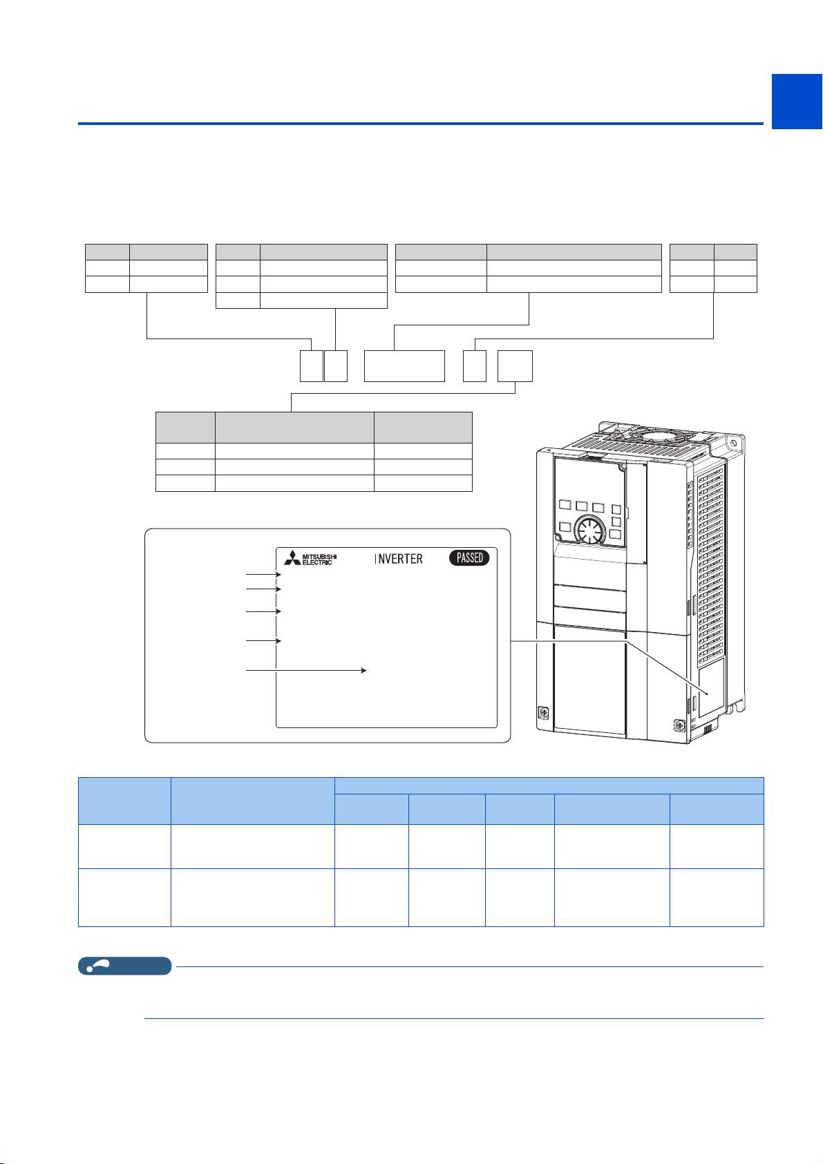
1.1 Product checking and accessories
Rating plate
Input rating
Output rating
SERIAL
Inverter model
,1387;;;;;
02'(/)5)
287387;;;;;
6(5,$/;;;;;;;;;
0$'(,1;;;;;
Country of origin
F R - F 8 2 0 -
00046
- 1
400V class
Symbol Voltage class
200V class
4
2
CA
Symbol Type
*1
FM
-2
-1
Symbol Description
0.75K to 560K
00023 to 12120
LD rated inverter capacity (kW)
SLD rated inverter current (A)
Symbol Structure, functionality
Standard model0
Separated converter type
2
IP55 compatible model6
Symbol
Circuit board coating
(conforming to IEC60721-3-3 3C2/3S2)
WithoutNone
With
With
Plated conductor
Without
With
Without
-06
*2
-60
Unpack the product and check the rating plate and the capacity plate of the inverter to ensure that the model agrees with the
order and the product is intact.
Inverter model
1
2
3
4
5
6
7
Type Monitor output
FM (terminal FM
equipped model)
CA (terminal CA
equipped model)
*1 Specification differs by the type. Major differences are shown in the following table.
Terminal FM (pulse train output)
Terminal AM (analog voltage
output (0 to ±10 VDC))
Terminal CA (analog current
output (0 to 20 mADC))
Terminal AM (analog voltage
output (0 to ±10 VDC))
Built-in EMC
filter
OFF Sink logic 60 Hz
ON Source logic 50 Hz
Control logic
frequency
Initial setting
Rated
Pr.19 Base
frequency voltage
9999 (same as the
power supply voltage)
8888 (95% of the
power supply voltage)
8
9
10
Pr.570 Multiple
rating setting
1 (LD rating)
0 (SLD rating)
*2 Applicable for the FR-F820-00340(7.5K) or higher, and the FR-F840-00170(7.5K) or higher.
NOTE
• In this Instruction Manual, the inverter model name consists of the inverter rated current and the applicable motor capacity.
Example) FR-F820-00046(0.75K)
1. INTRODUCTION
1.1 Product checking and accessories
17
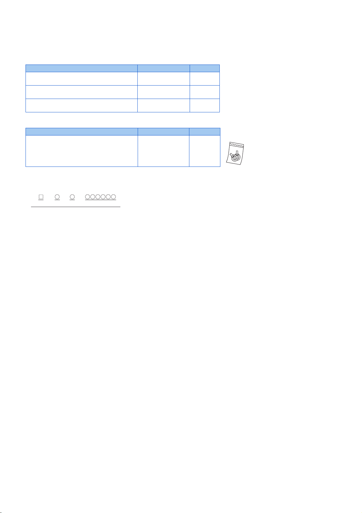
Accessory
Rating plate example
Symbol Year Month Control number
SERIAL
• Fan cover fixing screws
These screws are necessary for compliance with the EU Directives. (Refer to the Instruction Manual (Startup).)
Capacity Screw size (mm) Quantity
FR-F820-00105(2.2K) to FR-F820-00250(5.5K)
FR-F840-00083(3.7K), FR-F840-00126(5.5K)
FR-F820-00340(7.5K), FR-F820-00490(11K)
FR-F840-00170(7.5K), FR-F840-00250(11K)
FR-F820-00630(15K) to FR-F820-00930(22K)
FR-F840-00310(15K) to FR-F840-00620(30K)
• Eyebolt for hanging the inverter
Capacity Eyebolt size Quantity
FR-F840-04320(185K) to FR-F840-06830(315K) M12 2
M3 × 35 1
M3 × 35 2
M4 × 40 2
SERIAL number
The SERIAL consists of one symbol, two characters indicating the production year
and month, and six characters indicating the control number.
The last digit of the production year is indicated as the Year, and the Month is
indicated by 1 to 9, X (October), Y (November), or Z (December).
1.1 Product checking and accessories
1. INTRODUCTION
18
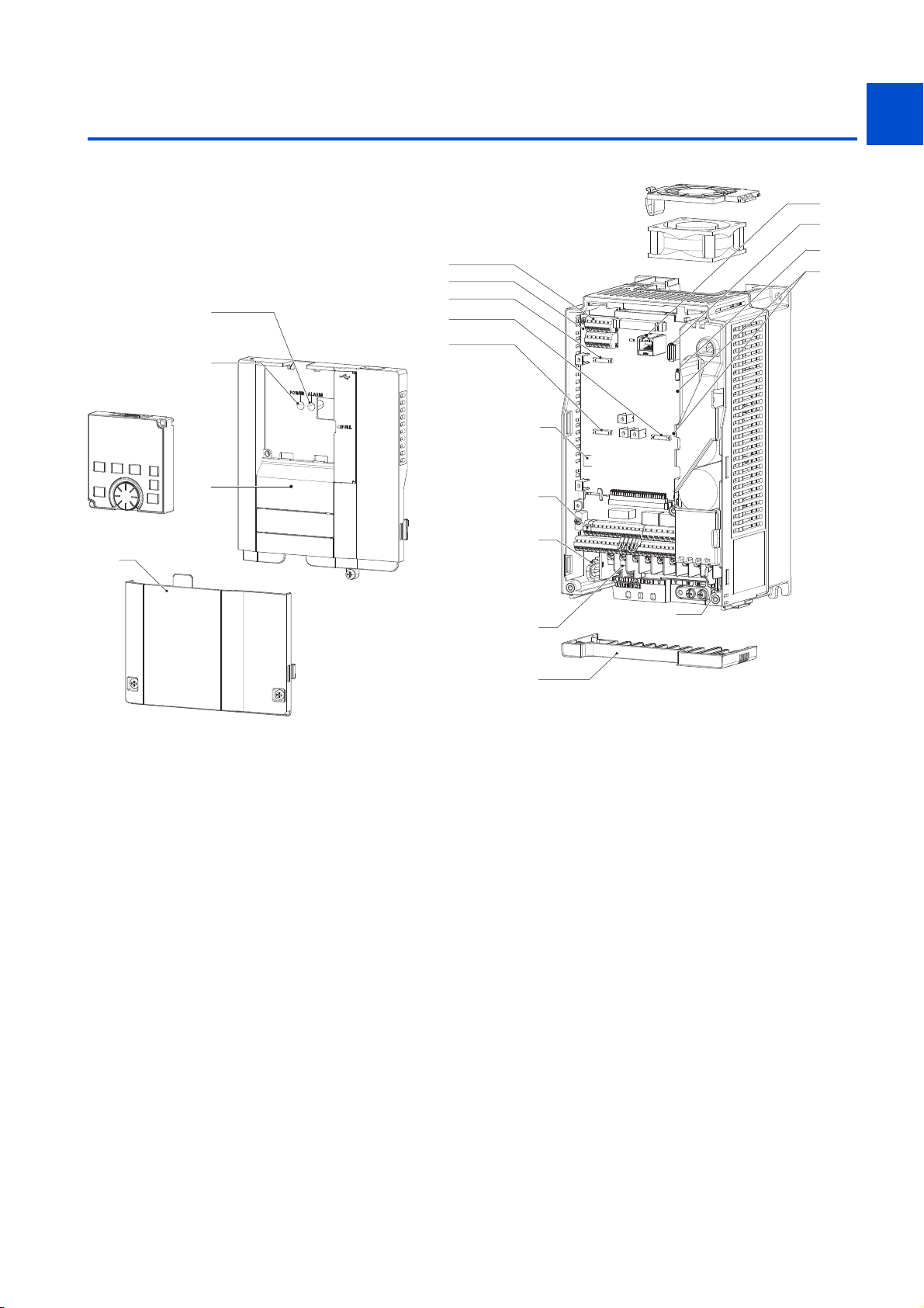
1.2 Component names
Component names are as follows.
(o)
(p)
(s)
(d)
(e)
(h)
(g)
1
2
(a)
(b)
(t)
(f)
(c)
(u)
3
4
5
(i)
6
(q)
(j)
7
(k)
(r)
8
(l)
(m)
9
(n)
10
1. INTRODUCTION
1.2 Component names
19

Symbol Name Description
(a) PU connector
(b) USB A connector Connector for a USB memory device. 74
(c) USB mini B connector
(d) RS-485 terminals Used for RS-485, MODBUS RTU, or BACnet communication. 75
(e)
(f) Plug-in option connector 1
(g) Plug-in option connector 2
(h) Plug-in option connector 3
(i)
(j) Control circuit terminal block Connect cables for the control circuit. 58
(k) EMC filter ON/OFF connector Turn ON/OFF the switch to enable/disable the EMC filter. 88
(l) Main circuit terminal block Connect cables for the main circuit. 47
(m) Charge lamp Stays ON while the power is supplied to the main circuit. 48
(n) Wiring cover
(o) Alarm lamp Turns ON when the protective function of the inverter is activated. 48
(p) Power lamp
(q) Front cover (upper side)
(r) Front cover (lower side) Remove this cover for wiring. 30
(s) Operation panel (FR-DU08) Used to operate or monitor the inverter. 106
(t) Cooling fan
(u)
Terminating resistor selection switch
(SW1)
Voltage/current input selection switch
assembly (SW2)
Switches (SW3 and SW4) for
manufacturer setting
Connector for the operation panel or the parameter unit. Also used for RS-485
communication.
Connector for a personal computer. Enables communication with FR
Configurator2.
Select whether or not to use the terminating resistor for RS-485
communication.
Connector for a plug-in option or a communication option.
Select voltage or current for the input via terminals 2 and 4. 330
This cover is removable without unplugging cables (FR-F820-00930(22K) or
lower, FR-F840-00620(30K) or lower)
Stays ON while the power is supplied to the control circuit (via terminals R1/
L11 and S1/L21).
Remove this cover for the installation of the product, installation of a plug-in
(communication) option, RS-485 terminal wiring, switching of the voltage/
current input selection switch assembly (SW2), etc.
Cools the inverter (provided for FR-F820-00105(2.2K) or higher, FR-F84000083(3.7K) or higher).
Do not change the initial setting (OFF ).
OFF
ON
Refer to
73
74
75
Instruction
Manual of
the option
50
48
30
601
—
page
1. INTRODUCTION
20
1.2 Component names
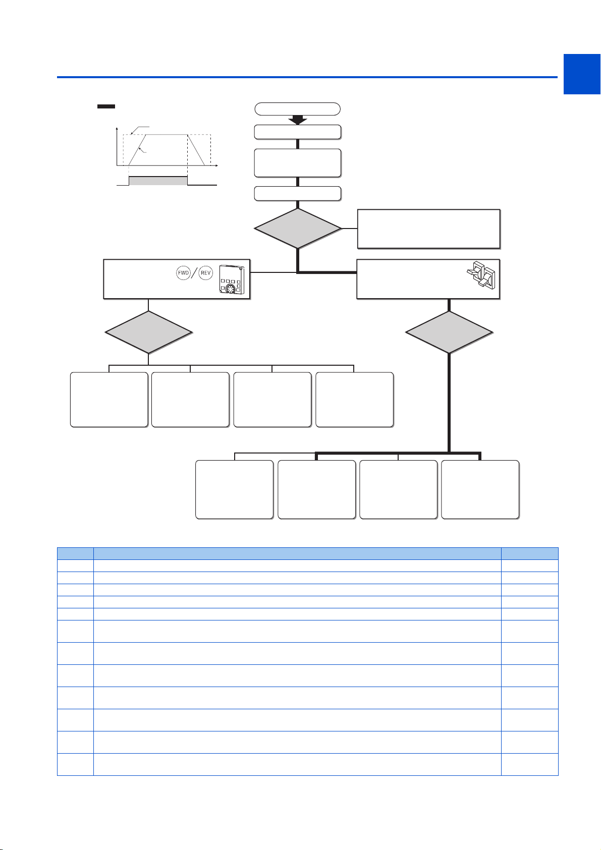
1.3 Operation steps
How
o
to give a start
command?
How to
w
give a frequency
command?
give a frequency
command?
1
Frequency
(Hz)
Start command
Start command with
on the operation panel (PU)
Set from the
PU (operation panel/
parameter unit).
(PU)
(e) (f) (g) (h)
: Initial setting
Frequency command
Inverter
output
frequency
ON
How to
give a frequency
command?
Change frequency
with ON/OFF switches
connected to terminals
(multi-speed setting)
(External)
Time
(S)
Step of operation
Installation/mounting
Wiring of the power
supply and motor
Control mode selection
How
to give a start
command?
Perform frequency
setting by a voltage
output device
(Connection across
terminals 2 and 5)
(External) (External)
Perform frequency
setting by a current
output device
(Connection across
terminals 4 and 5)
(a)
(b)
(c)
Start command via the PU connector
and RS-485 terminal of the inverter
and plug-in option (Communication)
Connect a switch, relay, etc.
to the control circuit
terminal block of the inverter
to give a start command. (External)
How to
give a frequency
command?
2
3
4
(d)
5
6
7
8
9
Set from the
PU (operation panel/
parameter unit).
(PU) (External) (External) (External)
Change of frequency
with ON/OFF switches
connected to terminals
(multi-speed setting)
Perform frequency
setting by a voltage
output device
(Connection across
terminals 2 and 5)
Perform frequency
setting by a current
output device
(Connection across
terminals 4 and 5)
(i) (j) (k) (l)
Symbol Overview Refer to page
(a) Install the inverter. 34
(b) Perform wiring for the power supply and the motor. 48
(c) Select the control method (V/F control, Advanced magnetic flux vector control, or PM motor control). 169
(d) Give the start command via communication. 473
(e) Give both the start and frequency commands from the PU. (PU operation mode) 116
(f)
(g)
(h)
(i)
(j)
(k)
(l)
Give the start command from the PU and the frequency command via terminals RH, RM, and RL. (External/PU
combined operation mode 2)
Give the start command from the PU and the frequency command by voltage input via terminal 2. (External/PU
combined operation mode 2)
Give the start command from the PU and the frequency command by current input via terminal 4. (External/PU
combined operation mode 2)
Give the start command via terminal STF or STR and the frequency command from the PU. (External/PU
combined operation mode 1)
Give the start command via terminal STF or STR and the frequency command via terminals RH, RM, and RL.
(External operation mode)
Give the start command via terminal STF or STR and the frequency command by voltage input via terminal 2.
(External operation mode)
Give the start command via terminal STF or STR and the frequency command by current input via terminal 4.
(External operation mode)
118
119
120
122
123
124
127
10
1. INTRODUCTION
1.3 Operation steps
21

1.4 About the related manuals
The manuals related to FR-F800 are as follows.
Manual name Manual number
FR-F800 Instruction Manual (Startup) IB-0600545
FR-F802 (Separated Converter Type) Instruction Manual (Hardware) IB-0600550ENG
FR-CC2 (Converter unit) Instruction Manual IB-0600543ENG
FR-F806 (IP55/UL Type 12 specification) Instruction Manual (Hardware) IB-0600676ENG
FR Configurator2 Instruction Manual IB-0600516ENG
FR-A800/F800 PLC Function Programming Manual IB-0600492ENG
FR-A800/F800 Safety Stop Function Instruction Manual BCN-A23228-001
1. INTRODUCTION
22
1.4 About the related manuals

CHAPTER 2
CHAPTER 2
2.1 Peripheral devices ..................................................................................................................................................24
2.2 Removal and reinstallation of the operation panel or the front covers....................................................................30
2.3 Installation of the inverter and enclosure design ....................................................................................................34
2.4 Terminal connection diagrams................................................................................................................................43
2.5 Main circuit terminals ..............................................................................................................................................47
2.6 Control circuit..........................................................................................................................................................58
2.7 Communication connectors and terminals..............................................................................................................73
2.8 Connection of stand-alone option units ..................................................................................................................76
INSTALLATION AND WIRING
4
5
6
7
8
9
10
23
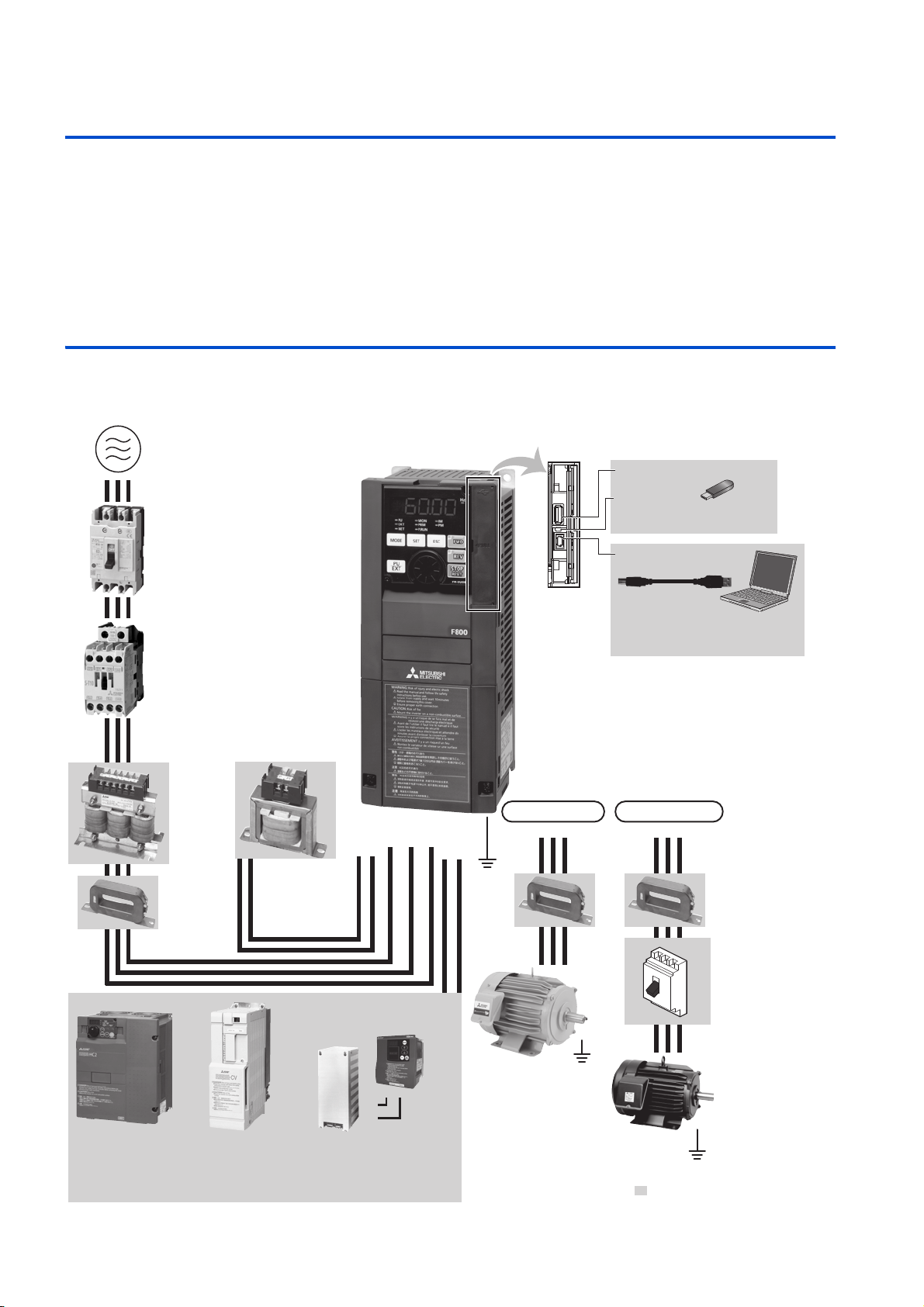
2 INSTALLATION AND WIRING
This chapter explains the installation and the wiring of this product.
Always read the instructions before use.
For the separated converter type, refer to the "INSTALLATION AND WIRING" in the FR-F802 (Separated Converter Type)
Instruction Manual (Hardware).
For the IP55 compatible model, refer to the "INSTALLATION AND WIRING" in the FR-F806 (IP55/UL Type 12 specification)
Instruction Manual (Hardware).
2.1 Peripheral devices
2.1.1 Inverter and peripheral devices
(b) Three-phase AC power supply
(c) Moulded case circuit breaker
(MCCB) or earth leakage current
breaker (ELB), fuse
(d) Magnetic contactor (MC)
(e) AC reactor
(FR-HAL)
(g) Line noise
filter
(FR-BLF)
(f) DC reactor
(FR-HEL)
(a) Inverter
R/L1 S/L2 T/L3
P1P/+
N/-P/+
(Ground)
IM connection
Earth
UVW
(m) USB connector
USB host
(A connector)
Communication
status indicator
(LED)(USB host)
USB device
(Mini B connector)
PM connection
U
VW
USB
Personal computer
(FR Configurator 2)
(n) EMC filter
(ferrite core)
(FR-BSF01, FR-BLF)
(h) High power factor
converter
(FR-HC2)
2. INSTALLATION AND WIRING
24
2.1 Peripheral devices
(i) Power regeneration
common converter
(FR-CV)
(j) Power regeneration
converter (MT-RC)
(k) Brake unit
(FR-BU2, FR-BU)
P/+
PR
(l) Resistor unit
(FR-BR, MT-BR5)
P/+
(p) Contactor
Example) No-fuse
switch
(DSN type)
(o) Induction motor
PR
Earth
(Ground)
Earth (Ground)
: Install these options as required.
(q) IPM motor
(MM-EFS, MM-THE4)

Symbol Name Overview
The life of the inverter is influenced by the surrounding air temperature.
The surrounding air temperature should be as low as possible within the
permissible range. This must be noted especially when the inverter is
(a) Inverter (FR-F800)
(b) Three-phase AC power supply Must be within the permissible power supply specifications of the inverter. 612
(c)
(d) Magnetic contactor (MC)
(e) AC reactor (FR-HAL)
(f) DC reactor (FR-HEL)
(g) Noise filter (FR-BLF)
(h) High power factor converter (FR-HC2)
(i)
(j)
(k)
(l)
(m) USB connection
(n) Noise filter (FR-BSF01/FR-BLF)
(o) Induction motor Connect a squirrel-cage induction motor. —
(p)
(q) IPM motor (MM-EFS/MM-THE4)
Molded case circuit breaker (MCCB), earth
leakage circuit breaker (ELB), or fuse
Power regeneration common converter
*1
(FR-CV
Power regeneration converter (MT-RC
Brake unit (FR-BU2/FR-BU
Resistor unit (FR-BR
Contactor
Example) No-fuse switch (DSN type)
*1 Compatible with the FR-F820-02330(55K) or lower and the FR-F840-01160(55K) or lower.
*2 Compatible with the FR-F820-03160(75K) or higher and the FR-F840-01800(75K) or higher.
)
*1
/BU*1)
*1
/MT-BR5*2)
installed in an enclosure.
Incorrect wiring may lead to damage of the inverter. The control signal lines
must be kept fully away from the main circuit lines to protect them from
noise.
The built-in EMC filter can reduce the noise.
Must be selected carefully since an inrush current flows in the inverter at
power ON.
Install this to ensure safety.
Do not use this to start and stop the inverter. Doing so will shorten the life
of the inverter.
Install this to suppress harmonics and to improve the power factor.
An AC reactor (FR-HAL) (option) is required when installing the inverter
near a large power supply system (1000 kVA or more). Under such
condition, the inverter may be damaged if you do not use a reactor.
Select a reactor according to the applied motor capacity.
Install this to suppress harmonics and to improve the power factor.
Select a reactor according to the applied motor capacity.
For the FR-F820-03160(75K) or higher and the FR-F840-01800(75K) or
higher, always connect the FR-HEL.
When using the DC reactor with the FR-F820-02330(55K) or lower, or the
FR-F840-01160(55K) or lower, remove the jumper across terminals P/+ and
P1 before connecting the DC reactor to the inverter.
The FR-F820-02330(55K) or lower and the FR-F840-01160(55K) or lower
are equipped with the common mode choke.
Suppresses the power supply harmonics significantly. Install this as
required.
Provides a large braking capability. Install this as required.
*2
)
Allows the inverter to provide the optimal regenerative braking capability.
Install this as required.
Connect between the inverter and a personal computer with a USB (ver.
1.1) cable.
Use a USB memory device to copy parameter settings or use the trace
function.
Install this to reduce the electromagnetic noise generated from the inverter.
The noise filter is effective in the range from about 0.5 to 5 MHz.
A wire should be wound four turns at maximum.
Connect this for an application where a PM motor is driven by the load even
while the inverter power is OFF. Do not open or close the contactor while
the inverter is running (outputting).
Use the specified motor. An IPM motor cannot be driven by the commercial
power supply.
Refer to
34,43,88
26
96
95
95
86
79
80
81
76
74
86
—
615
page
1
2
3
4
5
6
7
8
9
10
2. INSTALLATION AND WIRING
2.1 Peripheral devices
25

NOTE
• To prevent an electric shock, always earth (ground) the motor and inverter.
NOTE
• Do not install a power factor correction capacitor, surge suppressor, or capacitor type filter on the inverter's output side. Doing
so will cause the inverter shut off or damage the capacitor or surge suppressor. If any of the above devices is connected,
immediately remove it. When installing a molded case circuit breaker on the output side of the inverter, contact the
manufacturer of the molded case circuit breaker.
• Electromagnetic wave interference:
The input/output (main circuit) of the inverter includes high frequency components, which may interfere with the
communication devices (such as AM radios) used near the inverter. To minimize interference, enabling the built-in EMC filter
or installing an external EMC filters is effective. (Refer to page 88.)
• For details of options and peripheral devices, refer to the respective Instruction Manual.
• A PM motor cannot be driven by the commercial power supply.
• A PM motor is a motor with permanent magnets embedded inside. High voltage is generated at the motor terminals while the
motor is running. Before closing the contactor at the output side, make sure that the inverter power is ON and the motor is
stopped.
2.1.2 Peripheral devices
Check the model of the inverter you purchased. Appropriate peripheral devices must be selected according to the capacity.
Refer to the following table for right selection.
LD rating (Pr.570 Multiple rating setting = "1")
• 200 V class
Motor
output
(kW)
0.75 FR-F820-00046(0.75K) 10 A 10 A S-T10 S-T10
1.5 FR-F820-00077(1.5K) 15 A 15 A S-T10 S-T10
2.2 FR-F820-00105(2.2K) 20 A 15 A S-T10 S-T10
3.7 FR-F820-00167(3.7K) 30 A 30 A S-T21 S-T10
5.5 FR-F820-00250(5.5K) 50 A 40 A S-T25 S-T21
7.5 FR-F820-00340(7.5K) 60 A 50 A S-T35 S-T25
11 FR-F820-00490(11K) 75 A 75 A S-T35 S-T35
15 FR-F820-00630(15K) 125 A 100 A S-T50 S-T50
18.5 FR-F820-00770(18.5K) 150 A 125 A S-T65 S-T50
22 FR-F820-00930(22K) 175 A 125 A S-T100 S-T65
30 FR-F820-01250(30K) 225 A 150 A S-T100 S-T100
37 FR-F820-01540(37K) 250 A 200 A S-N150 S-N125
45 FR-F820-01870(45K) 300 A 225 A S-N180 S-N150
55 FR-F820-02330(55K) 400 A 300 A S-N220 S-N180
75 FR-F820-03160(75K) — 400 A — S-N300
90 FR-F820-03800(90K) — 400 A — S-N300
110 FR-F820-04750(110K) — 500 A — S-N400
Inverter model
• Select an MCCB according to the power supply capacity.
• Install one MCCB per inverter. For the use in the United States or Canada, refer to "Instructions for UL and cUL" in the
Instruction Manual (Startup) or Instruction Manual (Hardware) to select an appropriate fuse or MCCB.
MCCB INV
MCCB INV
Molded case circuit breaker (MCCB) / earth
leakage circuit breaker (ELB) (type NF or NV)
Power factor improving AC/DC reactor Power factor improving AC/DC reactor
Not installed Installed Not installed Installed
M
M
Magnetic contactor (MC) for installation
on the inverter input side
2. INSTALLATION AND WIRING
26
2.1 Peripheral devices

• When the inverter capacity is larger than the motor capacity, select the MCCB and the MC according to the inverter model,
MCCB INV
MCCB INV
M
M
• When the breaker installed on the inverter input side is shut off, check for the wiring fault (short circuit), damage to internal
• The matrix shows the MC selected according to the standards of Japan Electrical Manufacturers' Association (JEM standards)
• When the inverter capacity is larger than the motor capacity, select the MCCB and the MC according to the inverter model,
• 400 V class
and select cables and the reactor according to the motor output.
parts of the inverter etc. The cause of the output shutoff must be identified and removed before turning ON the power of the
breaker.
for AC-1 class. The electrical durability of magnetic contactor is 500,000 times. When the MC is used for emergency stops
during motor driving, the electrical durability is 25 times. If using the MC for emergency stop during motor driving, select the
MC for the inverter input current according to the rated current against JEM 1038 standards for AC-3 class. When installing
an MC on the inverter output side to switch to the commercial-power supply operation while running a general-purpose motor,
select the MC for the rated motor current according to the rated current against JEM 1038 standards for AC-3 class.
and select cables and the reactor according to the motor output.
1
2
3
4
Motor
output
(kW)
0.75 FR-F840-00023(0.75K) 5 A 5 A S-T10 S-T10
1.5 FR-F840-00038(1.5K) 10 A 10 A S-T10 S-T10
2.2 FR-F840-00052(2.2K) 10 A 10 A S-T10 S-T10
3.7 FR-F840-00083(3.7K) 20 A 15 A S-T10 S-T10
5.5 FR-F840-00126(5.5K) 30 A 20 A S-T21 S-T12
7.5 FR-F840-00170(7.5K) 30 A 30 A S-T21 S-T21
11 FR-F840-00250(11K) 50 A 40 A S-T21 S-T21
15 FR-F840-00310(15K) 60 A 50 A S-T35 S-T21
18.5 FR-F840-00380(18.5K) 75 A 60 A S-T35 S-T35
22 FR-F840-00470(22K) 100 A 75 A S-T35 S-T35
30 FR-F840-00620(30K) 125 A 100 A S-T50 S-T50
37 FR-F840-00770(37K) 150 A 100 A S-T65 S-T50
45 FR-F840-00930(45K) 175 A 125 A S-T100 S-T65
55 FR-F840-01160(55K) 200 A 150 A S-T100 S-T100
75 FR-F840-01800(75K) — 200 A — S-T100
90 FR-F840-02160(90K) — 225 A — S-N150
110 FR-F840-02600(110K) — 225 A — S-N180
132 FR-F840-03250(132K) — 350 A — S-N220
150 FR-F840-03610(160K) — 400 A — S-N300
160 FR-F840-03610(160K) — 400 A — S-N300
185 FR-F840-04320(185K) — 400 A — S-N300
220 FR-F840-04810(220K) — 500 A — S-N400
250 FR-F840-05470(250K) — 600 A — S-N600
280 FR-F840-06100(280K) — 600 A — S-N600
315 FR-F840-06830(315K) — 700 A — S-N600
Inverter model
Molded case circuit breaker (MCCB) / earth
leakage circuit breaker (ELB) (type NF or NV)
Power factor improving AC/DC reactor Power factor improving AC/DC reactor
Not installed Installed Not installed Installed
Magnetic contactor (MC) for installation on
the inverter input side
5
6
7
8
9
10
NOTE
• Select an MCCB according to the power supply capacity.
• Install one MCCB per inverter. For the use in the United States or Canada, refer to "Instructions for UL and cUL" in the
Instruction Manual (Startup) or Instruction Manual (Hardware) to select an appropriate fuse or MCCB.
2. INSTALLATION AND WIRING
2.1 Peripheral devices
27
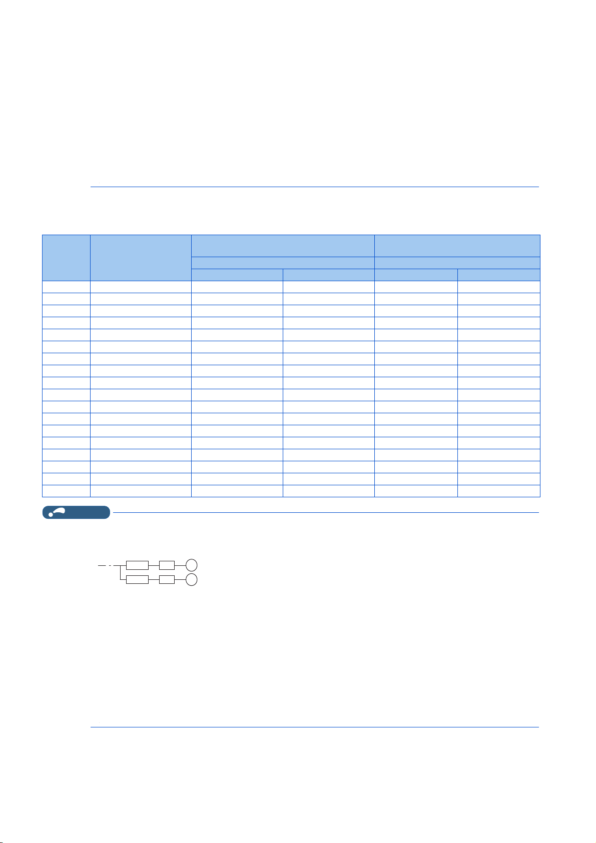
• When the inverter capacity is larger than the motor capacity, select the MCCB and the MC according to the inverter model,
NOTE
and select cables and the reactor according to the motor output.
• When the breaker installed on the inverter input side is shut off, check for the wiring fault (short circuit), damage to internal
parts of the inverter etc. The cause of the output shutoff must be identified and removed before turning ON the power of the
breaker.
• The matrix shows the MC selected according to the standards of Japan Electrical Manufacturers' Association (JEM standards)
for AC-1 class. The electrical durability of magnetic contactor is 500,000 times. When the MC is used for emergency stops
during motor driving, the electrical durability is 25 times. If using the MC for emergency stop during motor driving, select the
MC for the inverter input current according to the rated current against JEM 1038 standards for AC-3 class. When installing
an MC on the inverter output side to switch to the commercial-power supply operation while running a general-purpose motor,
select the MC for the rated motor current according to the rated current against JEM 1038 standards for AC-3 class.
SLD rating (Pr.570 Multiple rating setting = "0")
• 200 V class
Motor
output
(kW)
0.75 FR-F820-00046(0.75K) 10 A 10 A S-T10 S-T10
1.5 FR-F820-00077(1.5K) 15 A 15 A S-T10 S-T10
2.2 FR-F820-00105(2.2K) 20 A 15 A S-T10 S-T10
3.7 FR-F820-00167(3.7K) 30 A 30 A S-T21 S-T10
5.5 FR-F820-00250(5.5K) 50 A 40 A S-T25 S-T21
7.5 FR-F820-00340(7.5K) 75 A 50 A S-T35 S-T35
11 FR-F820-00490(11K) 100 A 75 A S-T50 S-T35
15 FR-F820-00630(15K) 125 A 100 A S-T65 S-T50
18.5 FR-F820-00770(18.5K) 150 A 125 A S-T65 S-T50
22 FR-F820-00930(22K) 175 A 150 A S-T100 S-T65
30 FR-F820-01250(30K) 225 A 175 A S-N150 S-T100
37 FR-F820-01540(37K) 300 A 225 A S-N150 S-N150
45 FR-F820-01870(45K) 350 A 250 A S-N180 S-N150
55 FR-F820-02330(55K) 400 A 350 A S-N220 S-N180
75 FR-F820-03160(75K) — 500 A — S-N300
90 FR-F820-03800(90K) — 500 A — S-N400
110 FR-F820-03800(90K) — 500 A — S-N400
132 FR-F820-04750(110K) — 600 A — S-N600
Inverter model
• Select an MCCB according to the power supply capacity.
• Install one MCCB per inverter. For the use in the United States or Canada, refer to "Instructions for UL and cUL" in the
Instruction Manual (Startup) or Instruction Manual (Hardware) to select an appropriate fuse or MCCB.
MCCB INV
MCCB INV
• When the inverter capacity is larger than the motor capacity, select the MCCB and the MC according to the inverter model,
and select cables and the reactor according to the motor output.
• When the breaker installed on the inverter input side is shut off, check for the wiring fault (short circuit), damage to internal
parts of the inverter etc. The cause of the output shutoff must be identified and removed before turning ON the power of the
breaker.
• The matrix shows the MC selected according to the standards of Japan Electrical Manufacturers' Association (JEM standards)
for AC-1 class. The electrical durability of magnetic contactor is 500,000 times. When the MC is used for emergency stops
during motor driving, the electrical durability is 25 times. If using the MC for emergency stop during motor driving, select the
MC for the inverter input current according to the rated current against JEM 1038 standards for AC-3 class. When installing
an MC on the inverter output side to switch to the commercial-power supply operation while running a general-purpose motor,
select the MC for the rated motor current according to the rated current against JEM 1038 standards for AC-3 class.
Molded case circuit breaker (MCCB) / earth
leakage circuit breaker (ELB) (type NF or NV)
Power factor improving AC/DC reactor Power factor improving AC/DC reactor
Not installed Installed Not installed Installed
M
M
Magnetic contactor (MC) for installation
on the inverter input side
2. INSTALLATION AND WIRING
28
2.1 Peripheral devices

• 400 V class
NOTE
MCCB INV
MCCB INV
M
M
Motor
output
(kW)
0.75 FR-F840-00023(0.75K) 5 A 5 A S-T10 S-T10
1.5 FR-F840-00038(1.5K) 10 A 10 A S-T10 S-T10
2.2 FR-F840-00052(2.2K) 10 A 10 A S-T10 S-T10
3.7 FR-F840-00083(3.7K) 20 A 15 A S-T10 S-T10
5.5 FR-F840-00126(5.5K) 30 A 20 A S-T21 S-T12
7.5 FR-F840-00170(7.5K) 30 A 30 A S-T21 S-T21
11 FR-F840-00250(11K) 50 A 40 A S-T21 S-T21
15 FR-F840-00310(15K) 60 A 50 A S-T35 S-T21
18.5 FR-F840-00380(18.5K) 75 A 60 A S-T35 S-T35
22 FR-F840-00470(22K) 100 A 75 A S-T35 S-T35
30 FR-F840-00620(30K) 125 A 100 A S-T50 S-T50
37 FR-F840-00770(37K) 150 A 125 A S-T65 S-T50
45 FR-F840-00930(45K) 175 A 150 A S-T100 S-T65
55 FR-F840-01160(55K) 200 A 175 A S-N150 S-T100
75 FR-F840-01800(75K) — 225 A — S-N150
90 FR-F840-01800(75K) — 225 A — S-N150
110 FR-F840-02160(90K) — 225 A — S-N180
132 FR-F840-02600(110K) — 350 A — S-N220
150 FR-F840-03250(132K) — 400 A — S-N300
160 FR-F840-03250(132K) — 400 A — S-N300
185 FR-F840-03610(160K) — 400 A — S-N300
220 FR-F840-04320(185K) — 500 A — S-N400
250 FR-F840-04810(220K) — 600 A — S-N600
280 FR-F840-05470(250K) — 600 A — S-N600
315 FR-F840-06100(280K) — 700 A — S-N600
355 FR-F840-06830(315K) — 800 A — S-N800
Inverter model
Molded case circuit breaker (MCCB) / earth
leakage circuit breaker (ELB) (type NF or NV)
Power factor improving AC/DC reactor Power factor improving AC/DC reactor
Not installed Installed Not installed Installed
Magnetic contactor (MC) for installation on
the inverter input side
1
2
3
4
5
6
7
8
9
• Select an MCCB according to the power supply capacity.
• Install one MCCB per inverter. For the use in the United States or Canada, refer to "Instructions for UL and cUL" in the
Instruction Manual (Startup) or Instruction Manual (Hardware) to select an appropriate fuse or MCCB.
• When the inverter capacity is larger than the motor capacity, select the MCCB and the MC according to the inverter model,
and select cables and the reactor according to the motor output.
• When the breaker installed on the inverter input side is shut off, check for the wiring fault (short circuit), damage to internal
parts of the inverter etc. The cause of the output shutoff must be identified and removed before turning ON the power of the
breaker.
• The matrix shows the MC selected according to the standards of Japan Electrical Manufacturers' Association (JEM standards)
for AC-1 class. The electrical durability of magnetic contactor is 500,000 times. When the MC is used for emergency stops
during motor driving, the electrical durability is 25 times. If using the MC for emergency stop during motor driving, select the
MC for the inverter input current according to the rated current against JEM 1038 standards for AC-3 class. When installing
an MC on the inverter output side to switch to the commercial-power supply operation while running a general-purpose motor,
select the MC for the rated motor current according to the rated current against JEM 1038 standards for AC-3 class.
10
2. INSTALLATION AND WIRING
2.1 Peripheral devices
29
 Loading...