

Mitsubishi Electric FR-A800, FR-F800 Instruction Manual

INVERTER
FR-A800/F800
Safety Stop Function Instruction Manual
CONTENTS
1. GENERAL DESCRIPTION ............................................ 3
2. INSTALLATION AND WIRING...................................... 5
3. EXAMPLE OF SAFETY SYSTEM CONFIGURATION .... 9
4. TEST AND CHECKING FAILURE ............................... 12
5. SAFETY PARAMETERS OF FR-A800/F800 ................ 13
Compliance with the EU Machinery Directive – Functional Safety
To achieve functional safety, any work on the product such as wiring and inspections must be performed
according to the Instruction Manual by technicians who took a safety standard training.
Warning
Any misuse of safety function could lead to personal injury or death, property damage, or economic
loss. To ensure that the system complies fully with requirement of safety, make a system-level risk
assessment. Mitsubishi Electric Corporation. cannot assume responsibility for any system to
comply with safety directive.
To avoid an electric shock hazard, verify that the voltage on the bus capacitors has discharged
before performing any work on the inverter. Measure the DC bus voltage between the terminals P(+)
and N(-) or at test points (refer to your inverter’s Instruction Manual for locations and discharging
time). The voltage must be zero.
The safety stop function do not isolate electrically between the inverter and the motor. To avoid an
electric shock hazard, disconnect/isolate power to the inverter and verify to ensure that the voltage
is zero before performing any work on the motor (refer to your inverter’s Instruction Manual for
discharging time).
Caution
The information of this manual is merely a guide for proper installation.
Mitsubishi Electric Corporation. cannot assume responsibility for the compliance or the
noncompliance to any code, national, local, or otherwise for the proper installation of this equipment.
A hazard of personal injury and/or equipment damage exists if codes are ignored during installation.
2
1 GENERAL DESCRIPTION
R/L1 S/L2 T/L3
U
V
W
M
So (SO)
SOC
S1
S2
G G
FR-A800/F800
SIC
SD
RESET
Emergency
stop button
Safety relay module
/ Safety programmable controller
PC
Gate
Driver
Gate
Driver
IGBTs
Fuse
CPU
+24V
24VDC
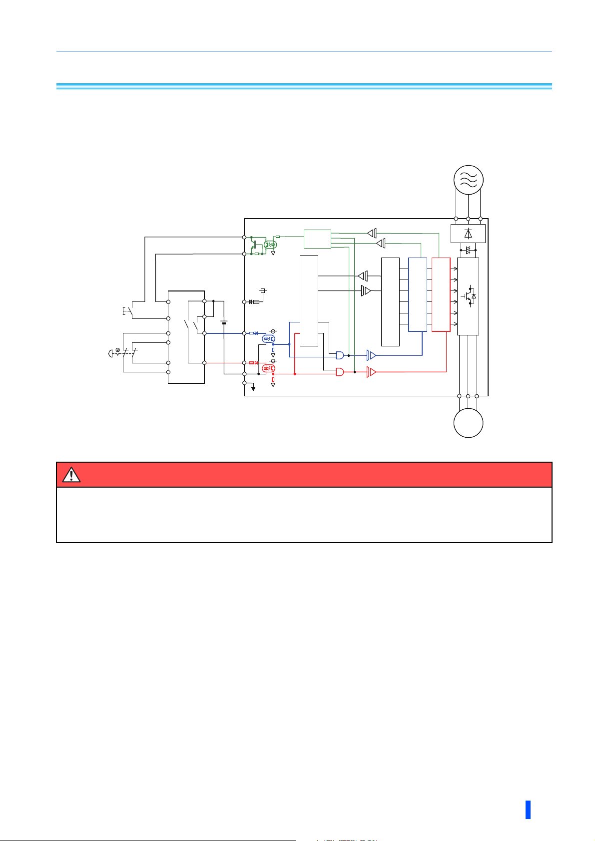
Features
The safety stop function of the Mitsubishi Electric FR-A800/F800 inverter can be used to prevent the inverter
from supplying rotational energy to motors. Dual input terminals S1 and S2 can be used to cut off the gate-drive
power to the IGBT.
Logic
ASIC
Figure 1 FR-A800/F800 safety stop function diagram
Warning
Disconnecting the power to the gate driver by the safety stop function does not isolate electrically
between the inverter and the motor. To avoid an electric shock hazard, disconnect power to the
inverter and verify that the main circuit capacitor voltage is zero (across terminals P and N) before
performing any work on the motor (refer to your inverter’s Instruction Manual for discharging time).
GENERAL DESCRIPTION
3
SafetystopfunctionwithSIL3certification
,1387;;;;;
02'(/
287387;;;;;
6(5,$/;;;;;;;;;
0$'(,1;;;;;
SERIAL
number
Country
of origin
The Mitsubishi Electric FR-A800/F800 inverters now comply with safety integrity level 3 (SIL 3) of the IEC
EC61508:2010 functional safety standard.
• Target models
Mitsubishi Electric FR-A800/F800 inverters
• Change of the compliance
The Mitsubishi Electric FR-A800/F800 inverters now comply with SIL 3.
Table 1 Compliance with SIL 3
Before change After change
Safety
performance
(Standards
certified by a thirdparty certification
body)
ISO13849-1:2008 Category 3/PLd
IEC62061:2005 / IEC61800-5-2:2007 /
IEC61508 SIL2
IEC60204-1:2010 / IEC61800-5-2:2007 Stop category 0
• Schedule
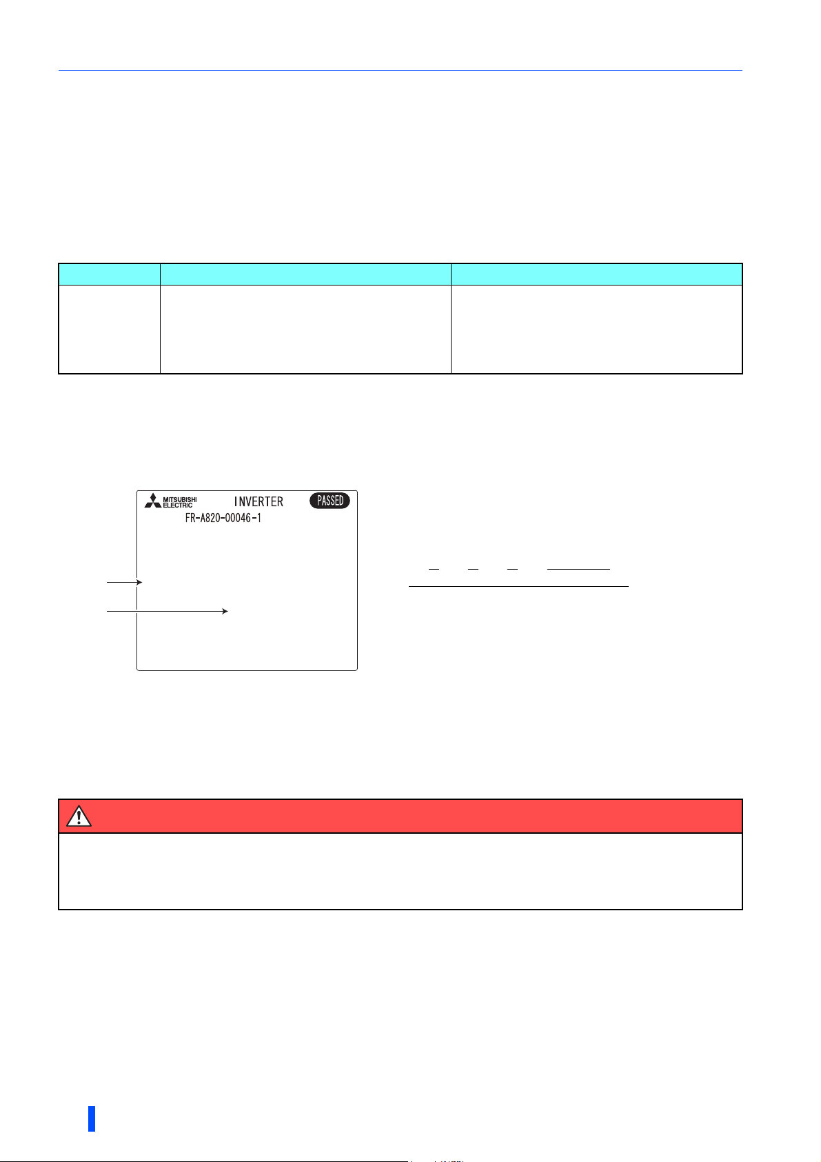
Check the SERIAL number indicated on the inverter rating plate or package.
For the products manufactured in Japan, this change has been made sequentially from the June 2018 production.
For the products manufactured in China, this change has been made sequentially from the July 2018 production.
Figure 2 Rating plate example
ISO13849-1:2015 Category 3/PLe
IEC62061:2015 / IEC61800-5-2:2016 /
IEC61508:2010 SIL3
IEC60204-1:2016 / IEC61800-5-2:2016 Stop category 0
Symbol Year Month Control number
SERIAL
The SERIAL consists of one symbol, two characters indicating the
production year and month, and six characters indicating the
control number.
The last digit of the production year is indicated as the Year, and
the Month is indicated by 1 to 9, X (October), Y (November), or Z
(December).
• Third-party certification body
Safety Integrity Level (SIL) 3:
TÜV SÜD
Safety Integrity Level (SIL) 2:
TUV Rheinland as before, or TÜV SÜD alternatively.
Warning
The misuse of safety function leads to personal injury or death, property damage, or economic loss.
To ensure that the system complies fully with requirement of safety, make a system-level risk
assessment. Mitsubishi Electric C
comply with safety standards.
orporation
. cannot assume responsibility for any system to
4
GENERAL DESCRIPTION
2 INSTALLATION AND WIRING
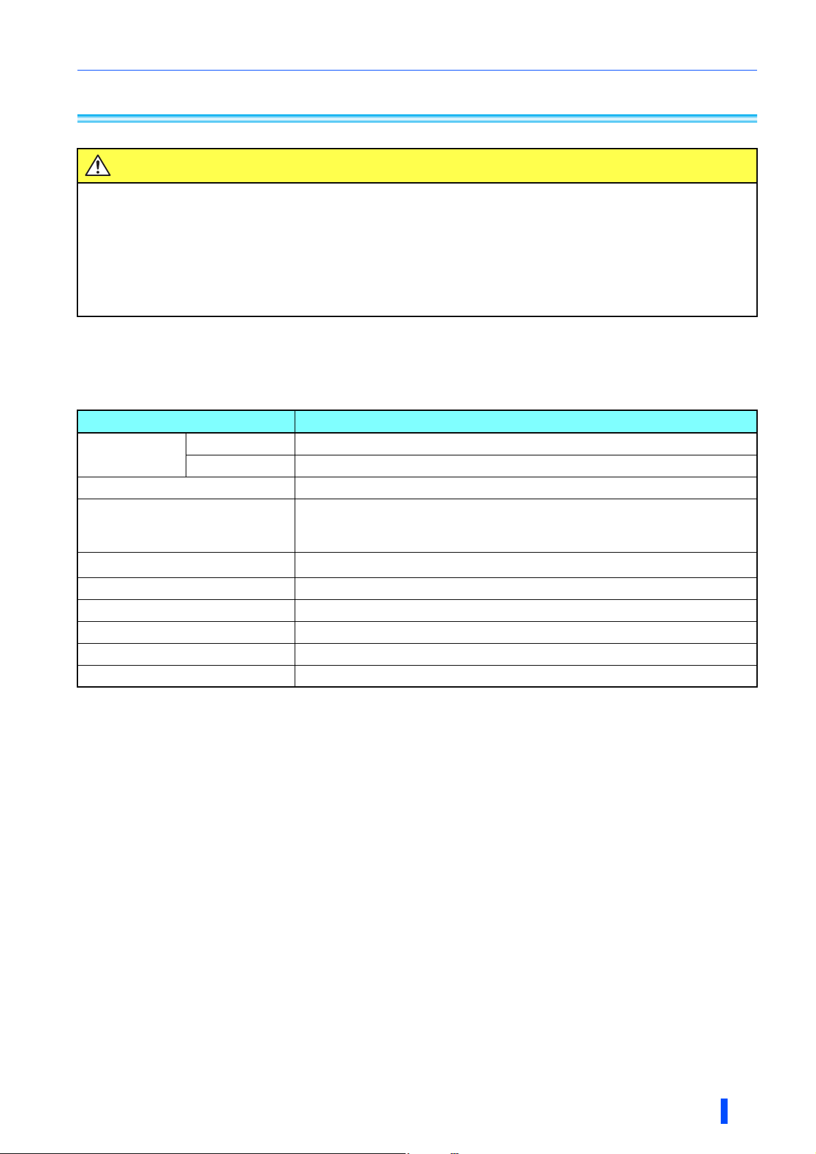
Caution
The following information is merely a guide for proper installation.
Mitsubishi Electric Corporation. cannot assume responsibility for the compliance or the
noncompliance to any code, national, local, or otherwise for the proper installation of this equipment.
A hazard of personal injury and/or equipment damage exists if codes are ignored during installation.
Ensure the safety relay unit and the FR-A800/F800 inverter are mounted closely in an enclosure
meeting IP54 and all interconnection wiring is short and protected against open and short circuit
faults. Refer ISO/IEC13849-2.
Installation
The safety stop function of the Mitsubishi Electric FR-A800/F800 inverter should be used under the following
conditions and environment.
Table 2 Conditions and environment for using the safety stop function
Item Condition
Surrounding air
temperature
Storage temperature -20ºC to +65ºC
Ambient humidity
Vibration
Altitude Maximum 2500 m
Atmosphere Indoors (free from corrosive gas, flammable gas, oil mist, dust and dirt)
Overvoltage category III or lower
Pollution degree II or lower
Mounting Wall mounting / vertical orientation
LD, ND, HD
SLD -10ºC to +40ºC (non-freezing)
∗1 -10ºC to +50ºC (non-freezing)
∗2
With circuit board coating (conforming to IEC60721-3-3 3C2/3S2): 95% RH or
less (non-condensing),
Without circuit board coating: 90% RH or less (non-condensing)
2
5.9 m/s
∗3 or less at 10 to 55 Hz (directions of X, Y, Z axes)
∗4
∗1 The ND and HD ratings can be selected only for the FR-A800 inverter.
∗2 Temperature applicable for a short time, e.g. in transit.
∗3 2.9 m/s
∗4 For the installation at an altitude above 1,000 m, derate the rated current 3% per 500 m.
2
or less for the FR-A840-04320(160K) / FR-F840-04320(185K) or higher.
INSTALLATION AND WIRING
5
 Loading...