

MITSUBISHI ELECTRIC
Frequency
Inverter
FR-F 740 EC/E1
Technical Catalogue
2004/2005

The new FR-F 740 inverter series
The new FR-F 740 frequency inverters are available with outputs
from 0.75 – 630 kW and are ideal for applications with pump and
The Power-Saving
Inverters
fan drives.
They use a 3-phase AC power supply and have an output
frequency range of 0.5 – 400 Hz.
Further Publications within the Factory Automation Range
Technical Catalogues Frequency Inverters
Product catalogue for frequency inverters and accessories
of the FR-S 500, FR-E 500 and FR-A 500 series
Technical
Catalogues
Additional Services
You will find current information on updates, alterations, new items and technical support on MITSUBISHI ELECTRIC's web pages
(www.mitsubishi-automation.com).
The products section of the MITSUBISHI home site includes various documents for the whole product range offered by MITSUBISHI ELECTRIC
as well as the current version of this catalogue. All manuals and catalogues can be downloaded for your convenience. Manuals and catalogues are
available in multiple language. Please check for availability.
Technical Catalogues MELSERVO and Motion Controllers
Product catalogues for MR-J2 series amplifiers, servo motors
and motion controllers with SSCNET connection
PLC Technical Catalogues
Product catalogues for programmable logic controllers and
accessories for the MELSEC series
Networks Technical Catalogue
Product catalogue for Master and Slave modules as well as
accessories for the use of programmable logic controllers in
open networks and MELSEC networks
HMI Technical Catalogue
Product catalogue for operator terminals, process visualisation and
programming software as well as accessories
About this product catalogue
Due to the constantly growing product range, technical alteration, and new or changed characteristical features, this catalogue is updated
frequently.
Texts, figures and diagrams shown in this product catalogue are intended exclusively for explanation and assistance in planning and ordering the fre
quency inverter series FR-F 700 EC/E1 and the associated accessories. Only the manuals supplied with the units are relevant for installation, commis
sioning and handling of the units and accessories. The information given in these documentations must be read before installation and commission
ing of the units or software.
Should questions arise with regard to the planning of modules described in this product catalogue, do not hesitate to contact your nearest office
listed on the last page of this document.
© MITSUBISHI ELECTRIC EUROPE B.V. 11/2004 (1st edition)
2
FR-F 740 EC/E1
MITSUBISHI ELECTRIC
-
-
-

FREQUENCY INVERTER FR-F 740 EC/E1
YSTEM DESCRIPTION
S
Introduction to the FR-F740 series . . . . . . . . . . . . . . . . . . . . . . . . . . . . . . . . . . . . . . . . . . . . . . . . . . . . . . . . . . . . . . . . . . . . . . . . . 4
웇
Energy conservation mode . . . . . . . . . . . . . . . . . . . . . . . . . . . . . . . . . . . . . . . . . . . . . . . . . . . . . . . . . . . . . . . . . . . . . . . . . . . . . . . 5
웇
Control functions and communications . . . . . . . . . . . . . . . . . . . . . . . . . . . . . . . . . . . . . . . . . . . . . . . . . . . . . . . . . . . . . . . . . . . 6
웇
Operation and maintenance . . . . . . . . . . . . . . . . . . . . . . . . . . . . . . . . . . . . . . . . . . . . . . . . . . . . . . . . . . . . . . . . . . . . . . . . . . . . . 10
웇
Specifications . . . . . . . . . . . . . . . . . . . . . . . . . . . . . . . . . . . . . . . . . . . . . . . . . . . . . . . . . . . . . . . . . . . . . . . . . . . . . . . . . . . . . . . . . . . 12
웇
Terminal assignments. . . . . . . . . . . . . . . . . . . . . . . . . . . . . . . . . . . . . . . . . . . . . . . . . . . . . . . . . . . . . . . . . . . . . . . . . . . . . . . . . . . . 16
웇
OPERATION
Control panel FR-DU07 . . . . . . . . . . . . . . . . . . . . . . . . . . . . . . . . . . . . . . . . . . . . . . . . . . . . . . . . . . . . . . . . . . . . . . . . . . . . . . . . . . 18
웇
Control panel FR-PU04. . . . . . . . . . . . . . . . . . . . . . . . . . . . . . . . . . . . . . . . . . . . . . . . . . . . . . . . . . . . . . . . . . . . . . . . . . . . . . . . . . . 19
웇
PARAMETERS
Overview. . . . . . . . . . . . . . . . . . . . . . . . . . . . . . . . . . . . . . . . . . . . . . . . . . . . . . . . . . . . . . . . . . . . . . . . . . . . . . . . . . . . . . . . . . . . . . . . 22
웇
CONTENTS
PROTECTIVE FUNCTIONS
웇 Overview of protective functions . . . . . . . . . . . . . . . . . . . . . . . . . . . . . . . . . . . . . . . . . . . . . . . . . . . . . . . . . . . . . . . . . . . . . . . . . 28
웇 Resetting methods . . . . . . . . . . . . . . . . . . . . . . . . . . . . . . . . . . . . . . . . . . . . . . . . . . . . . . . . . . . . . . . . . . . . . . . . . . . . . . . . . . . . . . 31
APPLICATIONS
웇 Examples of applications. . . . . . . . . . . . . . . . . . . . . . . . . . . . . . . . . . . . . . . . . . . . . . . . . . . . . . . . . . . . . . . . . . . . . . . . . . . . . . . . . 32
ACCESSORIES
웇 Overview of internal and external options . . . . . . . . . . . . . . . . . . . . . . . . . . . . . . . . . . . . . . . . . . . . . . . . . . . . . . . . . . . . . . . . 34
웇
Noise filters. . . . . . . . . . . . . . . . . . . . . . . . . . . . . . . . . . . . . . . . . . . . . . . . . . . . . . . . . . . . . . . . . . . . . . . . . . . . . . . . . . . . . . . . . . . . . . 36
웇
Reactors. . . . . . . . . . . . . . . . . . . . . . . . . . . . . . . . . . . . . . . . . . . . . . . . . . . . . . . . . . . . . . . . . . . . . . . . . . . . . . . . . . . . . . . . . . . . . . . . . 37
웇
Brake units . . . . . . . . . . . . . . . . . . . . . . . . . . . . . . . . . . . . . . . . . . . . . . . . . . . . . . . . . . . . . . . . . . . . . . . . . . . . . . . . . . . . . . . . . . . . . . 38
웇
External brake resistors . . . . . . . . . . . . . . . . . . . . . . . . . . . . . . . . . . . . . . . . . . . . . . . . . . . . . . . . . . . . . . . . . . . . . . . . . . . . . . . . . . 39
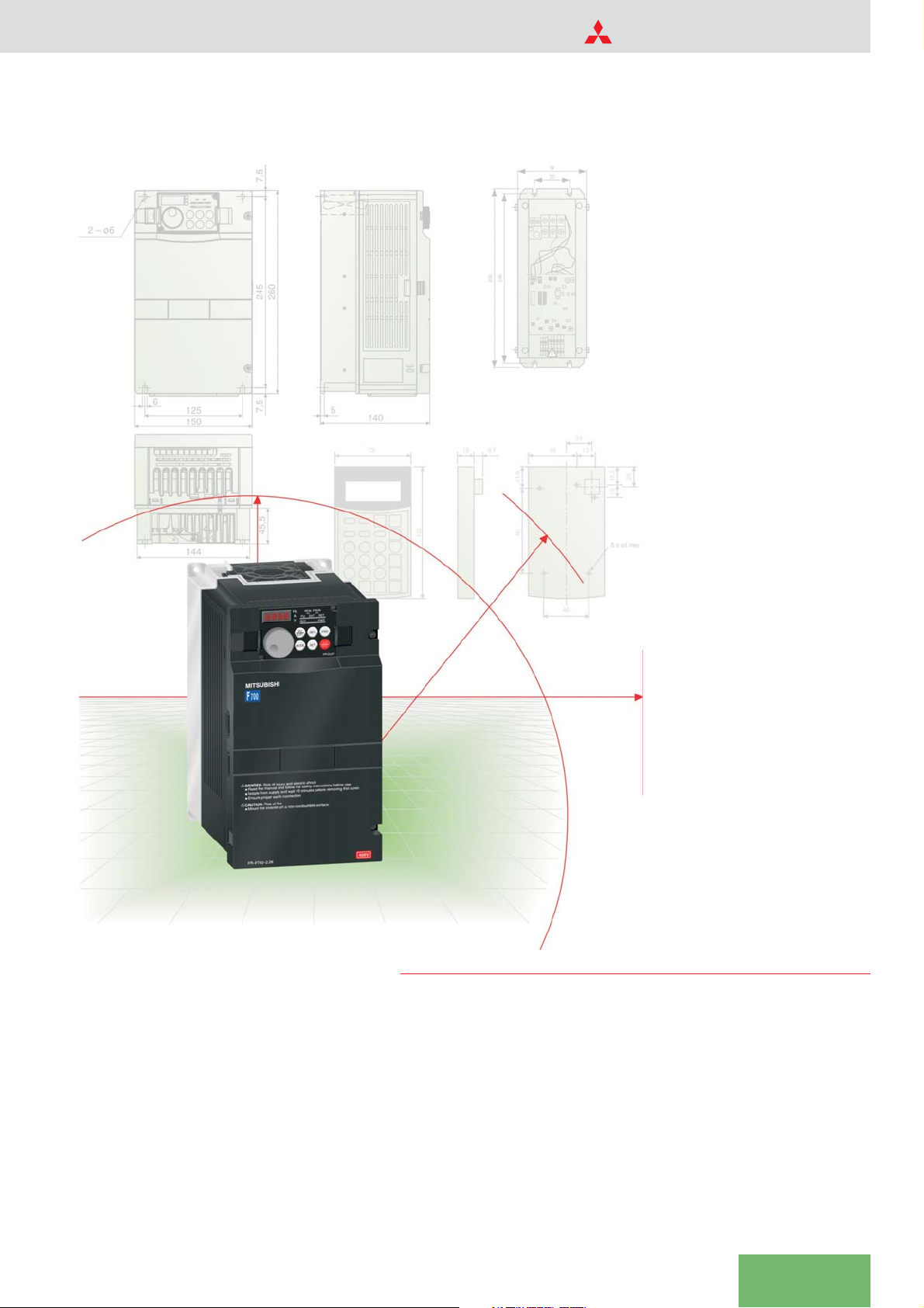
DIMENSIONS
웇
Control panels. . . . . . . . . . . . . . . . . . . . . . . . . . . . . . . . . . . . . . . . . . . . . . . . . . . . . . . . . . . . . . . . . . . . . . . . . . . . . . . . . . . . . . . . . . . 40
웇
Frequency inverters. . . . . . . . . . . . . . . . . . . . . . . . . . . . . . . . . . . . . . . . . . . . . . . . . . . . . . . . . . . . . . . . . . . . . . . . . . . . . . . . . . . . . . 41
웇
Filters . . . . . . . . . . . . . . . . . . . . . . . . . . . . . . . . . . . . . . . . . . . . . . . . . . . . . . . . . . . . . . . . . . . . . . . . . . . . . . . . . . . . . . . . . . . . . . . . . . . 46
웇
Reactors. . . . . . . . . . . . . . . . . . . . . . . . . . . . . . . . . . . . . . . . . . . . . . . . . . . . . . . . . . . . . . . . . . . . . . . . . . . . . . . . . . . . . . . . . . . . . . . . . 47
웇
Brake resistors . . . . . . . . . . . . . . . . . . . . . . . . . . . . . . . . . . . . . . . . . . . . . . . . . . . . . . . . . . . . . . . . . . . . . . . . . . . . . . . . . . . . . . . . . . . 48
웇
Brake units . . . . . . . . . . . . . . . . . . . . . . . . . . . . . . . . . . . . . . . . . . . . . . . . . . . . . . . . . . . . . . . . . . . . . . . . . . . . . . . . . . . . . . . . . . . . . . 49
APPENDIX
웇
Order form . . . . . . . . . . . . . . . . . . . . . . . . . . . . . . . . . . . . . . . . . . . . . . . . . . . . . . . . . . . . . . . . . . . . . . . . . . . . . . . . . . . . . . . . . . . . . . 50
웇
Index. . . . . . . . . . . . . . . . . . . . . . . . . . . . . . . . . . . . . . . . . . . . . . . . . . . . . . . . . . . . . . . . . . . . . . . . . . . . . . . . . . . . . . . . . . . . . . . . . . . . 51
MITSUBISHI ELECTRIC
FR-F 740 EC/E1
3
SYSTEM DESCRIPTION
The FR-F 740 Frequency Inverter
Mitsubishi Electric’s FR-F 740 series is a
completely new range of frequency invert
ers with truly exceptional power conserva
tion capabilities. These inverters are ideal
for pumps, ventilation fans and applica
tions with reduced overload requirements
such as:
Air conditioning systems, e.g. in building
management
Air extraction systems
앬
Fans and blowers
앬
Hydraulics systems
앬
Compressors
앬
Sewage and drains systems
앬
Ground water pumps
앬
Heat pumps
앬
Drive systems with high idling rates
앬
These inverters are very user-friendly and
they are available with output ratings
matched to users’ real needs.
The FR-F 740 is available in versions with
outputs from 0.75 – 640 kW. All the inver
ters in the series are designed for connecti
on to 3~ 380–480 V/500 V (50/60Hz) power
supplies.
The output frequency range is 0.5 – 400 Hz.
-
-
-
-
P.R UN
MON
Hz
8888
P.RUN
MON
Hz
NET
EXT
A
PU
FWD
V
REV
PU
FWD
REV
EXT
STOP
SET
MODE
RESET
FR-DU07
P.RUN
MON
Hz
NET
EXT
A
PU
FWD
V
REV
PU
FWD
REV
EXT
STOP
SET
MODE
RESET
FR-DU07
MITSUBISHI
700
FREQROL-F
ock
h
rics
t
.
ofinjury and elec
k
!
DANGER:Ris
-
Readthe manual
latefrom s
o
Is
reproper earth c
u
Ens
!
CAUTION:Ris
Mountthe inverter on a non-c
FR–F740–2.2K
pplyand wait 10 minutes before remov
u
offire
k
e
ionsbefore us
t
ruc
t
fetyins
a
hes
t
ndfollow
a
ver.
o
ngthis c
i
ion
t
nnec
o
.
e
rfac
u
ibles
t
mbus
o
400V
A
V
EXT
MODE
NET
EXT
PU
FWD
REV
PU
FWD
REV
STOP
SET
RESET
FR-DU07
Proven Technology with Advanced New Capabilities
Innovative performance
optimisation
The drive performance of the FR-F 740
series is optimised for the special needs of
fan and pump applications. Drives in appli
cations like these are characterised by a
load torque curve that increases by the
square of the motor speed (variable curve).
Of course, these frequency inverters can
also be used for standard applications with
constant load curves and a maximum over
load of 150%.
The outstanding features and characteris
tics of the FR-F 740 series include:
앬
Power-saving mode with display of the
energy savings
앬
-
PID control
앬
Extended PID control with sleep and
multi-motor switching functions
앬
Flexible 5-point V/f curve
앬
Continued operation after brief power
failures
-
앬
Automatic restart after instantaneous
power failures
앬
Flying start
앬
PTC temperature sensor input
-
앬
Switch motor to direct mains operation
앬
Active current limiting
앬
Optimum excitation control
앬
Regeneration avoidance function
앬
Traverse function
앬
Disable defined frequency ranges
앬
Selectable 2nd parameter set for differ
-
ent load characteristics
앬
Network support
4
FR-F 740 EC/E1
MITSUBISHI ELECTRIC
Intelligent Technology that Cuts Power Consumption
SYSTEM DESCRIPTION
Saving power with Mitsubishi
frequency converters
Reducing consumption and optimising the
utilisation of our valuable energy resources
is one of the greatest global environmental
challenges of our age.
Energy conservation mode is a standard
feature of the intelligent controller. It dyna
mically adjusts the voltage to motor requi
rements, eliminating unnecessary power
losses, which helps to further reduce po
wer consumption. Frequency inverters are
particularly effective at conserving energy
when they are used to control pumps and
fans.
Theamountofenergyconservation(hyste
resis) depends on the speed/torque fluc
tuations. The graph below provides an im
pressive example of the results of
intelligent control in a fan system.
100
Power consumption (%)
Mechanical solution
Constant torque
pattern (Pr. no.14 = 0)
Reduced torque
control
Frequency inverter
Rotational speed (= air quantity) (%)
pattern (Pr. no.14 = 1)
Energy conservation mode
(Pr.no.14=1,Pr.no.60=9)
-
-
1000
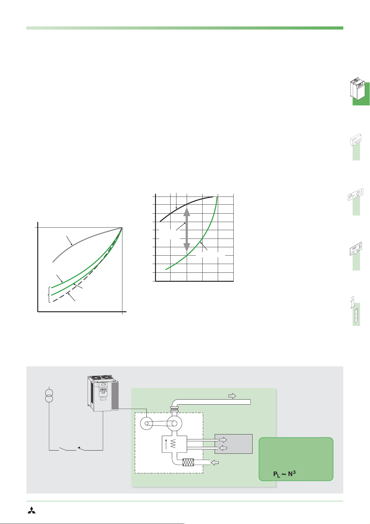
How do frequency inverters
conserve energy?
The illustration below shows a blower sys
tem in which the air flow is regulated by
controlling the motor with a frequency in
verter instead of with a damper on the ex
haust side.
The graph below compares the motor po
wer consumption of the frequency inverter
and damper solutions. At a flow rate of
60% the curve shows that the frequency
inverter system consumes a full 60% less
power than the motor with the damper
system.
-
-
Damper control (exhaust side)
100
90
80
70
60
Conserved
energy
50
40
30
Power consumption (%)
20
10
0
0 40 80 10060
Inverter control
Air quantity (%)
Potential savings
In addition to the ecological benefits fre
quency inverters can also save a great deal
of money by radically cutting power con
sumption.
-
-
Example:
Based on the graph on the left and an elec
-
tricity price of 14 cents per kWh, the follo
wing savings can be achieved with a sys
tem using a 75 kW motor:
Conventional mechanical solution
앬
At an air throughput of 60% the power
consumption is 90%, resulting in the
following annual costs:
75 kW x 0.9 x €0.14 x 24 h x 365 days
= €82,782
Frequency inverter solution
앬
At an air throughput of 60% the power
consumption is 30%, resulting in the
following annual costs:
75 kW x 0.3 x €0.14 x 24 h x 365 days
= €27,594
This means that the inverter solution saves
€55,188 per year compared to the conventional mechanical system!
Clearly, a frequency inverter will pay for
itself in a very short time – and one must
also remember that the potential savings
increase with the power ratings of the
motors used.
Energy savings control
The effect of energy savings can be confirmed using the control panel, via the
output terminals (CA, AM) and via net
works (network option required) with the
newly developed energy saving monitor.
-
-
-
-
-
-
Application with potential for power savings
Power
supply
3-phase 400 V
POWER
ALARM
EXT
MON
REV
REV
MODE
SET
RESET
DATAPORT
MITSUBISHI
0
0
F5
Hz
A
V
PU
FWD
FWD
STOP
Frequency inverter
Motor
Heat
exchanger
Example of air handling unit
MITSUBISHI ELECTRIC
Belt
Duct
Blower
Air filter
Exhaust
Cold source (chiller)
Heat source (heat pump)
Cold/hot
water
Air
The power PLrequired for a
fan or pump is proportional
to the cube of the rotational
speed
FR-F 740 EC/E1
5
SYSTEM DESCRIPTION
Intelligent Motor Control Functions
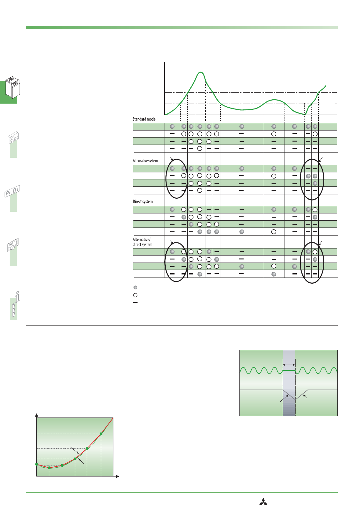
Extended PID control
The FR-F 740 series supports extended PID
control. This feature makes it possible to
connect the process status signal to the fre
quency inverter as a voltage signal
(0–10 V DC) or a current signal
(0/4–20 mA DC) and then use the analog
input calibration function of the inverter to
compensate minor controller-related fluc
tuations.
In addition to this the frequency inverter
can also control up to four motors succes
sively. This function is programmable; for
example, you can program it so that only
one motor is frequency-controlled and the
others are switched on and off under direct
mains power as required, or you can alter
nate between direct mains power and
frequency control for all four motors.
The graph on the right illustrates this multimotor switching function with a typical ex
ample.
When implementing an application like
this you must plan the necessary number
of magnetic power contactors and the required number of output signal terminals
on the inverter. Care must also be taken to
ensure that the mains power is never switched to the inverter output.
-
-
-
-
-
Q max
Q3
Q2
Q1
Motor 1 (M1)
Motor 2 (M2)
Motor 3 (M3)
Motor 4 (M4)
Motor 1 (M1)
Motor 2 (M2)
Motor 3 (M3)
Motor 4 (M4)
Motor 1 (M1)
Motor 2 (M2)
Motor 3 (M3)
Motor 4 (M4)
Motor 1 (M1)
Motor 2 (M2)
Motor 3 (M3)
Motor 4 (M4)
*
*1
*2
Flow rate
Time
*1
*
*2
Flexible 5-point V/f curve
The integrated flexible 5-point V/f curve
enables you to match the torque curve
perfectly to the characteristics of your
machine.
Together, the optimum excitation control
feature and the 5-point V/f curve achieve
significantly increased power savings.
V/f characteristic
V/F5
V/f pattern
Voltage
V/F1
0
V/F4
V/F3
V/F2
Base frequency
Torque
characteristic
Inverter controlled operation
Conventional operation
Stop
Automatic restart after instantane
ous power failures
In pump and fan applications normal ope
ration can be continued automatically af
ter brief power failures. The system simply
reactivates the coasting motor and auto
matically accelerates it back up to its
setpoint speed.
The graphic on the right shows how the
frequency inverter can respond to a brief
power outage. Instead of coasting down
completely and stopping, the motor is au
tomatically “caught” by the frequency in
verter and re-accelerated back up to its
previous speed.
* After switching the magnetic contactor the motor start
sequence switches from M1->M2->M3 to M2->M3->M1
-
-
-
Power supply
Output frequency
Deceleration
IPF
-
-
-
Restart
acceleration
6
FR-F 740 EC/E1
MITSUBISHI ELECTRIC
Innovative Features and Functions
SYSTEM DESCRIPTION
Flying start
Gentle restart of a rotating motor (e.g. fan
rotated by a draft), also in the opposite di
rection.
PTC temperature sensor input
The motor’s internal PTC temperature sen
sor can be connected to the inverter di
rectly. In combination with the electronic
temperature monitoring system this provi
des effective protection for the motor.
Active current limiting
Tried and tested capabilities like the active
current limiting feature have been retai
ned. The characteristics of the current limi
ter have now been further improved to
prevent unwanted triggering in response
to overcurrents. Transient overcurrents, for
example those generated when a motor
coasting in reverse is restarted or when an
input contactor is closed, will no longer
cause unwanted triggering of the current
limiter.
-
Magnetic flux vector control
The integrated motor flux vector control
system makes it possible to achieve high
torques, even at low motor speeds.
Optimum excitation control
You can also select the optimum excitation
control mode, which achieves yet more
power savings compared to conventional
inverters designed for pump and fan appli
cations.
The graph below demonstrates the kind of
improvements that are possible with this
control mode:
-
100
90
80
70
60
50
40
30
Motor efficiency (percent)
20
10
0
5% 10% 25% 50% 75% 100% 120%
Torque load (percentage of rated torque load)
Optimum excitation control mode
Standard energy saving inverter
No excitation control
Regeneration avoidance function
This function can prevent the inverter from
being shut down by regenerative overvol
tages when strong regenerative loads cau
se power to be released into the frequency
inverter (for example when braking the
motor or with loads that actively drive the
motor).
The inverter can automatically increase the
output frequency or disable the braking
-
ramp when a programmed threshold value
is reached. The response sensitivity, dyna
mics and working range are all adjustable.
For example, this function can prevent a
shutdownwithanovervoltageerrorwhen
the speed of a fan controlled by the inver
ter is increased by the draft from another
fan operating in the same ventilation duct.
The function then temporarily increases
the output frequency above the setpoint
value.
This function can also be used to brake lo
ads with the DC bus voltage, without using
braking modules.
Switching to direct mains operation
You can switch the motor to direct mains
operation by programming the contactor
relays accordingly and applying a control
signal to terminals L11 and L21 of the
inverter.
-
-
-
-
-
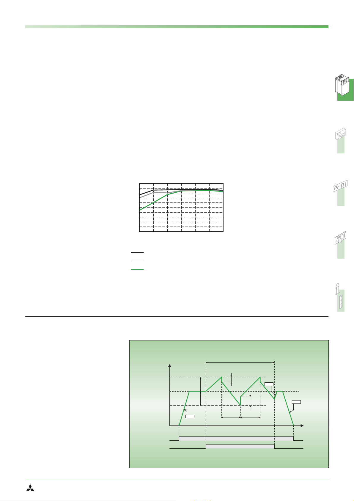
Traverse function
The traverse function of the FR-F740 is de
signed specifically for use in yarn-winding
applications in the textile industry.
This function performs a cyclical variation
of the output frequency as shown in the
graph on the right. The width of the fluc
tuation around the frequency setpoint va
lue and the ramp times are configurable
via setup parameters.
This function prevents the formation of the
unwanted “bands” in the wound yarn.
MITSUBISHI ELECTRIC
-
Output frequency
(Hz)
-
f0
Start/stop
signal
X37 signal
f1
f1
Pr.7
ON
ON
Traverse function
f2
t1
(Pr.596) t2 (Pr.597)
Pr.7
f3
Pr.8
FR-F 740 EC/E1
Time (s)
t(s)
7
SYSTEM DESCRIPTION
L W
ON ORKS
NETWORK
Extensive Communications Support
Extended I/Os for additional control
functions
The following I/Os are included as standard
equipment on the FR-F 740:
12 contact inputs
앬
3 analog inputs
앬
5 open collector outputs
앬
2 relay outputs
앬
2 analog outputs
앬
The contact inputs, open collector outputs
and relay outputs can all be used for a
wide range of functions.
Two of the analog inputs can be switched
from current to voltage. The switching sta
tus of the input and output terminals can
be displayed on the control panel.
Remote I/Os
Instead of using the remote I/Os of a PLC
you can use a network connection to both
read out the status of the frequency
inverter’s inputs and set its outputs.
Expansion slot
The frequency inverter has an expansion
slot that can be used to install an I/O expansion module or a network module. These modules are cards that are installed by
plugging them into the slot in the inverter.
See page 34 for a list of available modules.
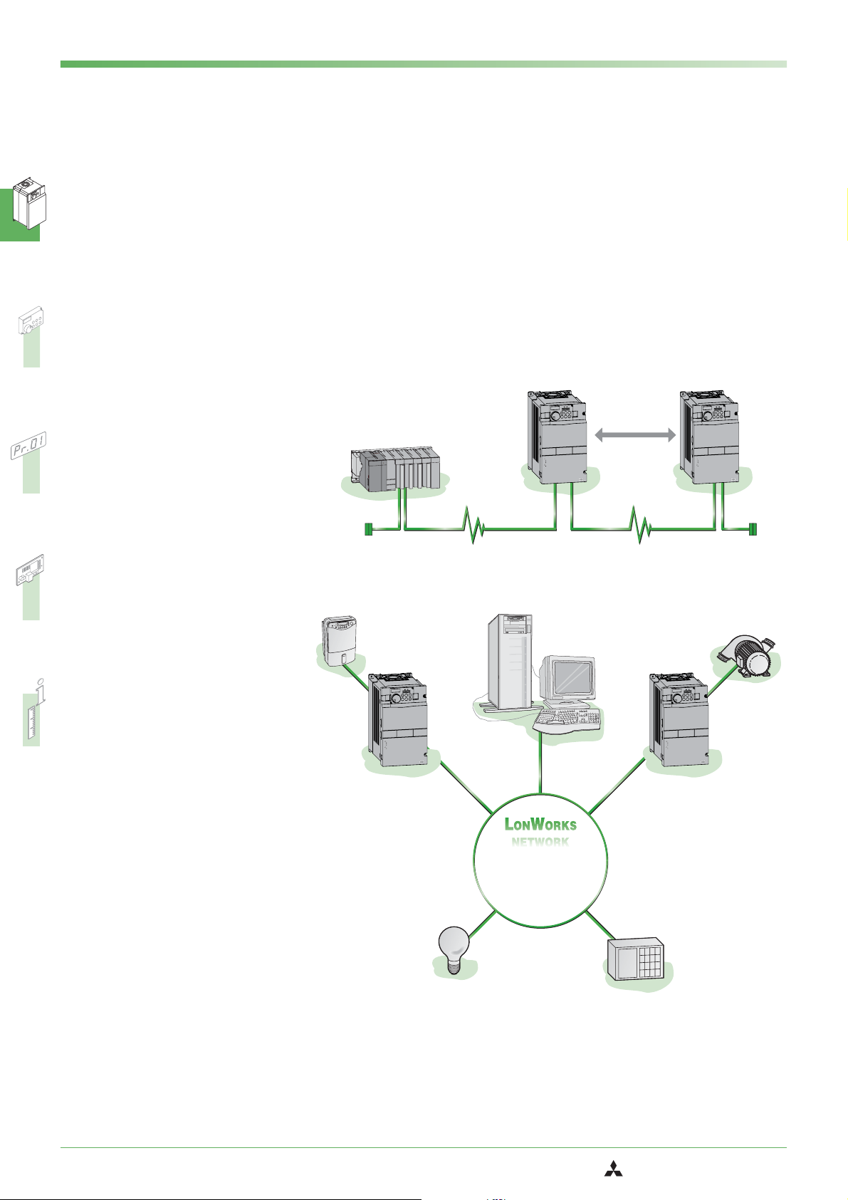
Support for integration in larger
networks
Open communications with standard indu
strial bus systems can be implemented ea
sily with optional expansion cards.
This makes it possible to integrate the fre
quency inverter in large-scale automation
systems.
-
PLC system
(e.g. Mitsubishi System Q)
1
Air conditioner
The following networks are supported by
the FR-F 740:
CC-Link
앬
Profibus/DP
앬
-
-
DeviceNet
앬
LON Works
앬
RS485 and Modbus RTU (standard)
앬
You can find a description of the network
cards on page 34.
FR-F 740
P.RUN
MON
Hz
NET
T
EX
A
PU
FWD
V
REV
PU
FWD
REV
EXT
OP
T
S
SET
MODE
RESET
FR-DU07
MITSUBISHI
700
FREQROL-F
!
DANGER:Riskofinjury and electric shock
Readthemanual andfollow the safety instructions before use.
Isolatefromsupplyand wait 10 minutes before removing this cover.
Ensureproperearth connection
!
CAUTION:Riskoffire
Mounttheinverteron a non-combustible surface.
400V
FR–F740–2.2K
FR-A7NC
CC-Link Network
PC for network
management
Up to 42
inverters
FR-F 740
MITSUBISHI
FREQROL-F
!
DANGER:Riskofinjury and electric shock
Readthemanual andfollow the safety instructions before use.
Isolatefromsupplyand wait 10 minutes before removing this cover.
Ensureproperearth connection
!
CAUTION:Riskoffire
Mounttheinverteron a non-combustible surface.
FR–F740–2.2K
700
ON
M
Hz
EXT
A
PU
V
REV
PU
R
EXT
SET
MODE
P.RUN
NET
FWD
FWD
V
E
STOP
RESET
FR-DU07
Pump
400V
FR-A7NC
Extended networking capabilities
The inverter comes with two serial ports as
standard equipment for integration in an
automation network. You can connect a
standard RJ45 network cable to the PU con
nector. there are also RS-485 terminals insi
de the inverter unit for connection to a mul
tidrop network via a normal cable, which
enables inexpensive networking of up to 32
nodes.
In addition to the Mitsubishi protocol you
can also use the Modbus RTU (binary) pro
tocol.
Programming via USB
You can configure the setup parameters
and monitor the frequency inverter via an
USB port with the optional USB 1.1
module.
FR-F 740
P.RUN
MON
Hz
NET
EXT
A
PU
FWD
V
REV
PU
FWD
REV
EXT
STOP
SET
MODE
RESET
FR-DU07
MITSUBISHI
700
FREQROL-F
400V
FR-A7NL
ON ORKS
L W
NETWORK
-
-
-
!
DANGER:Riskofinjury and electric shock
Readthemanual andfollow the safety instructions before use.
Isolatefromsupplyand wait 10 minutes before removing this cover.
Ensureproperearth connection
!
CAUTION:Riskoffire
Mounttheinverteron a non-combustible surface.
FR–F740–2.2K
-
FR-F 740
MON
Hz
A
PU
V
REV
PU
EXT
MODE
MITSUBISHI
700
FREQROL-F
!
DANGER:Riskofinjury and electric shock
Readthemanual andfollow the safety instructions before use.
Isolatefromsupplyand wait 10 minutes before removing this cover.
Ensureproperearth connection
!
CAUTION:Riskoffire
Mounttheinverteron a non-combustible surface.
FR–F740–2.2K
P.RUN
NET
EXT
FWD
FWD
REV
STOP
SET
RESET
FR-DU07
400V
FR-A7NL
Open network
topology
Lighting
Security system
8
FR-F 740 EC/E1
MITSUBISHI ELECTRIC
Environment-Friendly and Internationally Compatible
SYSTEM DESCRIPTION
Electromagnetic compatibility
New technologies have been used to signi
ficantly reduce the interference levels ge
-
nerated by this frequency inverter.
The FR-F 740 EC conforms to the strict elec
tromagnetic compatibility regulations of
the European Union (EMC Directive, Envi
ronment 2). In order to meet these stan
-
dards the FR-F700 inverters are fitted with
a new, integrated interference suppression
filter, which can easily be deactivated with
a jumper if necessary.
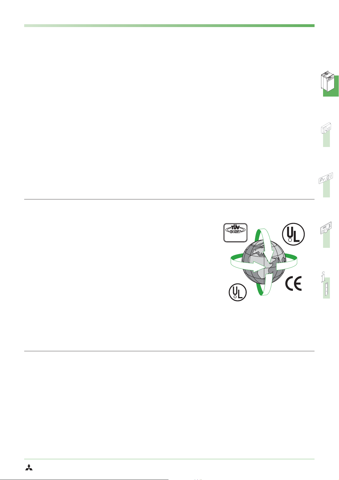
International standards
The inverters of the FR-F 740 EC series are
designed so that they can be used worldwide without any additional modifications
or certifications.
앬
The units conform to the international
CE, UL, cUL, Gost and CCC standards.
앬
User-selectable positive or negative
switching logic. Users can select posi
tive or negative switching logic for in
put and output signals, enabling
flexible and simple adaptation of the
units for varying world market
requirements.
앬
Extended input power voltage range:
3~ 380-480 V (up to 500 V for 01800 and
above), 50/60 Hz
Tolerance: −15%; +10%
-
-
You can also further limit the make current
and reduce network interference by fitting
the input of the inverter with an optional
AC reactor and a DC reactor, which is con
nected to special terminals on the inverter
-
unit.
The DC reactor is included as standard
equipment with models 00180 and above
andmustbeusedwiththem.
Multilingual programming/control unit
앬
(optional)
Support for a variety of international in-
앬
dustrial bus systems
앬
Internationally standardised, frequency
inverter configuration software package
for MS Windows, with multilingual user
interface
These features make the FR-F 740 EC a truly
international product that meets all relevant
standards and can be easily adjusted for na
tional requirements.
Circuit boards with two coats of pro
tective varnish
The frequency inverters with the E1 desig
nation (standard, type 02160 and above)
have circuit boards with two coats of pro
tective varnish.
This feature is available as an option for the
models up to type 01800. The twin coating
on the internal PCBs provides even better
protection against environmental influen
ces. This is particularly important in appli
cations sewage plants where the switchge
ar cabinets are exposed to aggressive
fermentation gases that can reduce the
service life of the equipment.
DIN ISO 9001 /
EN 29001
Zertifikat: 09 100 4371
-
R
C
-
-
-
-
-
-
R
SELV
MITSUBISHI ELECTRIC
FR-F 740 EC/E1
9
SYSTEM DESCRIPTION
MON
PU
EXT
NET
FWD
P. R U N
User-friendly Operation
Easy configuration with control
panel or software
The FR-DU07 control panel is included as
standard equipment with all the inverters
of this series. It makes operation of the in
verter simple and intuitive and displays
operating parameters and alarm messa
ges. The jog shuttle “digital dial” control
provides fast and efficient access to all key
drive parameters.
The optional FR-PU04 control panel featu
res a long-life LC-display with a backlight
and integrated numeric keypad for direct
entry of operating parameters. The user
interface can be displayed in eight diffe
rent languages. This panel is designed as a
remote unit that is connected to the inver
ter with a cable. It also supports definition
of user groups with which you can imple
ment editable parameter sets that can
then be selected as required for specific
applications.
-
-
MON
Hz
EXT
A
8.8.8.8.
-
8.8.8.8.
V
PU
EXT
MODE
PU
REV
REV
SET
-
FR-DU07
In addition to control panel operation the
frequency inverter can also be connected
to a standard PC via an RS-485 port and
operated from the PC with the optional
VFD setup software package. Using this
software you can configure, operate and
monitor multiple frequency inverters, eit
her in a network or directly from a single
PC or notebook computer. (See page 21 for
more details on this software package.)
P.R U N
NET
FWD
FWD
STOP
RESET
FR-DU07
50
50
SET
SHIFT
READ
PARAMETER UNIT
8
5
2
WRITE
FR-PU04
EXT
ESC
00
00
EXT
9
6
3
EXT
Hz
Hz
PU
FWD
REV
STOP
RESET
U
P
-
R
F
MON
HELP
4
0
-
- - - STOP
- - - STOP
7
4
1
0
-
User-friendly
In addition to allowing you to enter and
display configuration and control parame
ters the integrated control panel can also
be used to monitor and display current
operating data and alarm messages. The
information is output on a 4-digit LED dis
play.
You can monitor all the current status pa
rameters of both the inverter itself and the
connected motor. Problems and mal
-
functions are indicated by error codes.
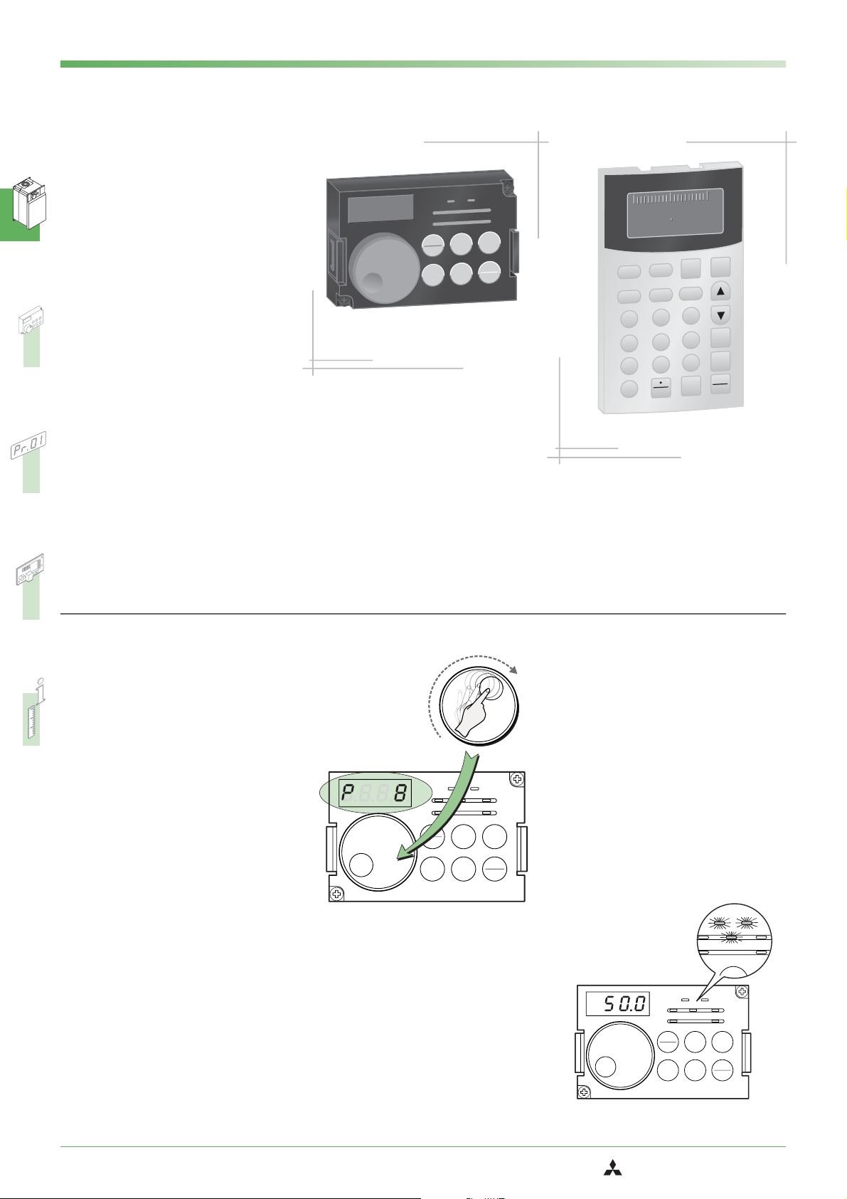
One-touch operation
Simple and intuitive configuration and
operation save both time and money. The
control panel’s jog shuttle “digital dial”
control provides much faster access to all
key drive parameters than would be possi
ble with conventional buttons and keys.
You can also use the dial to continuously
adjust the speed of the connected motor.
5
-
justing a para
meter with the
jog shuttle
-
-
Example: Ad-
Removable panel with parameter
-
copy function
The control panel is removable and can
also be connected installed remotely, for
example in the door of a switchgear cabi
net. It also features a useful copy function
with which you can copy the parameter
settings of one frequency inverter to
another.
4
-
3
2
1
Hz
MON
A
PU
V
REV
PU
EXT
MODE
EXT
REV
SET
6
P.R U N
NET
FWD
7
FWD
STOP
RESET
FR-DU07
8
Alarm log
The control panel stores an alarm log for
up to 8 alarm messages that can be dis
played and checked on the panel. The
alarm details in the log include frequency,
current, voltage and cumulative operating
time at the time of the alarm.
Switch between direct and external
control
The frequency inverter can be controlled
directly via the control panel (PU mode) or
via external signals (EXT mode).
-
Hz
A
V
PU
EXT
MODE
REV
P.R U N
MON
PU
EXT
REV
SET
NET
FWD
FWD
STOP
RESET
FR-DU07
-
10
FR-F 740 EC/E1
MITSUBISHI ELECTRIC
Long Service Life and Easy Maintenance
SYSTEM DESCRIPTION
New components for longer service
life
The components of this new generation of
frequency inverters are specified for a ser
vice life of 10 years (mean annual ambient
temperature 40°C, 80% load in an environ
ment free of aggressive gases, flammable
gases, oil mist, dust and dirt). Among other
things,thisismadepossiblebythe
newly-developed, long-life cooling fans
that are monitored by the inverter. The life
of the cooling fans can also be made signi
ficantly longer by using Parameter 244,
which controls the selective shutdown
feature.
Modern diagnostics functions furt
-
her extend service life
The ageing of the main circuit capacitors,
the control circuit power capacitor, the in
ternal cooling fans and the inrush current
limiter circuit can be checked with the mo
nitoring functions. If the inrush resistor
overheats an alarm is displayed.
The alarms for the main circuit capacitors,
control circuit capacitor, inrush current limiter and internal fans can all be output to
a network or via the optional FR-A7AY
module.
This makes it possible to prevent malfunctions by configuring diagnostics
alarms to be triggered when the end of the
service life is reached.
The inverter also has an internal program
that can evaluate the ageing of the main
circuit capacitors. This feature is only avai
lable when a motor is connected to the
inverter.
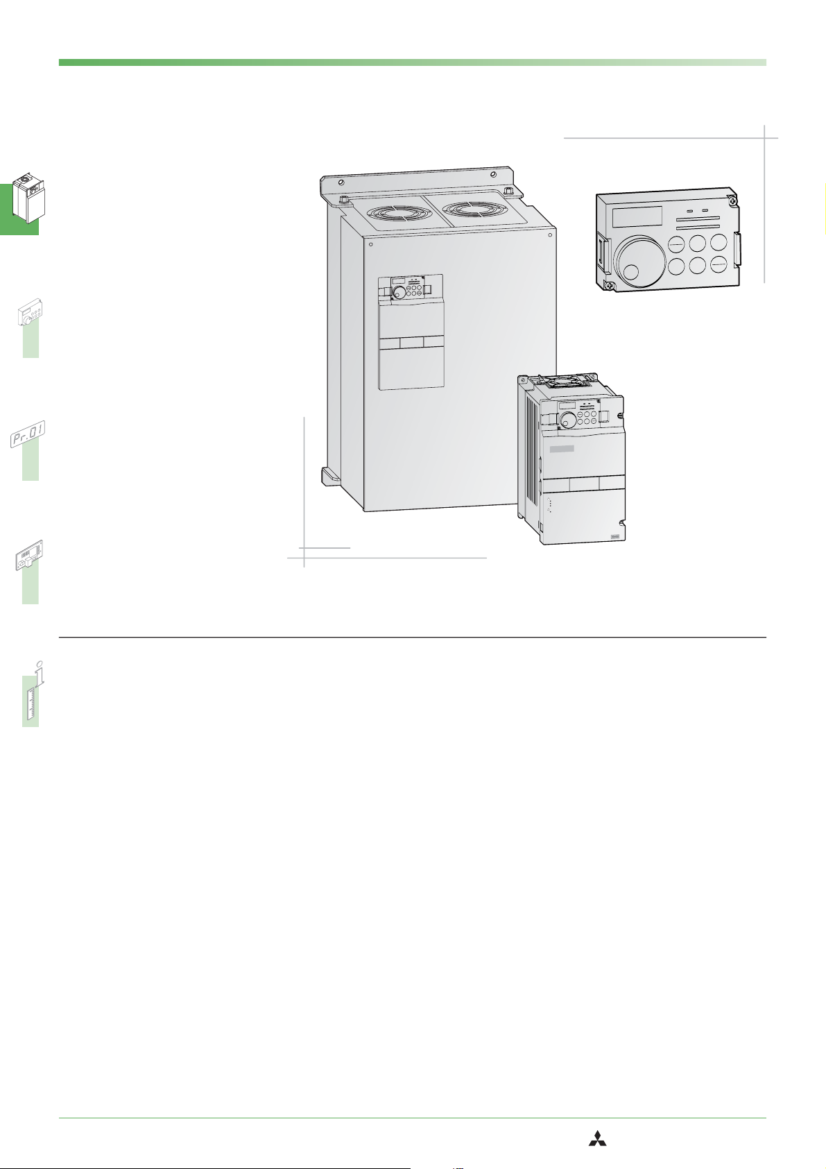
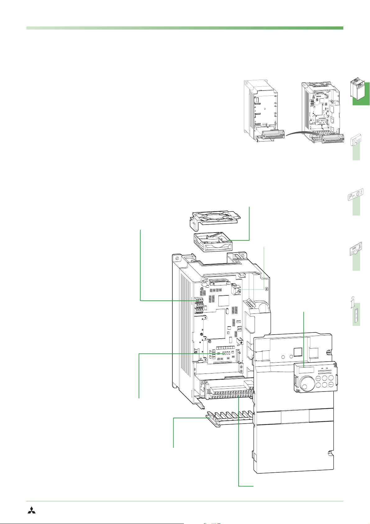
Easy replacement
The terminal block for the control circuit
connections is removable to enable easy
replacement of the inverter unit for servi
cing, which greatly facilitates both installa
tion and maintenance work. You can also
use the removable terminal block of the
FR-F500 series, which is compatible to the
FR-F700 series. However, please note that
some of the functions of the FR-F700 series
are not available when you use a terminal
block from the FR-F500 series.
-
-
-
RS-485
앬
interface
terminals
-
Replacement of the terminal block:
-
-
FR-F500
Easy replacement of the
앬
FR-F700
fan cassette
RJ45 connector for control
앬
panel and RS-485 communications port
앬
Removable
control panel
Service timer
The frequency inverters of this series all
have an integrated service timer that auto
matically triggers an alarm after a set num
ber of operating hours. This feature can be
used for monitoring the frequency inverter
itself or a peripheral component. The valu
es of the mean output current and the ser
vice timer can also be output as analog
signals.
Improved handling
The main cooling fan is easily accessible at
the top of the inverter unit, allowing quick
and easy replacement without removal of
the connection cables.
The cable guide comb (see illustration) is
removable and makes routing the cables
quick and trouble-free. After the cables
have been connected the cover can then
be replaced (for frequency inverters up to
type 00620).
MITSUBISHI ELECTRIC
-
-
-
8888
-
앬
Slot for optional
FWD
V
REV
PU
FWD
REV
EXT
STOP
SET
MODE
RESET
FR-DU07
P.RU N
MON
Hz
NET
EXT
A
PU
expansion cards
앬
Cable guide comb
앬
Removable terminal block
FR-F 740 EC/E1
11
SYSTEM DESCRIPTION
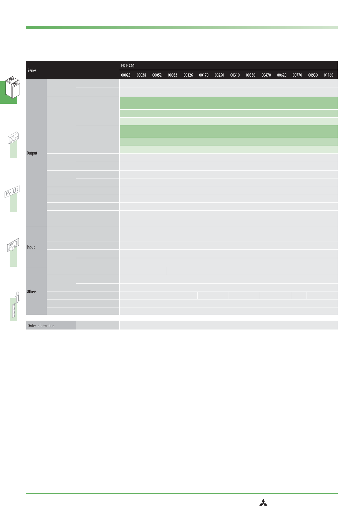
Specifications FR-F 740-00023 to -01160
Rated motor
capacity
[kW]
Rated
current
햷
[A]
Output capacity
[kVA]
Overload current
rating
Voltage
120% overlaod capacity
150% overlaod capacity
120%
overlaod
햶
capacity
150%
overlaod
capacity
120% overlaod capacity
150% overlaod capacity
120% overlaod capacity
150% overlaod capacity
햶
0.75 1.5 2.2 3.7 5.5 7.5 11 15 18.5 22 30 37 45 55
0.75 1.5 2.2 3.7 5.5 7.5 11 15 18.5 22 30 37 45 55
2.3
3.8
5.2
8.3
햷
I
rated
(2.0)
(3.2)
(4.4)
2.5 4.2 5.7 9.1 13.9 18.7 27.5 34.1 41.8 51.7 68.2 84.7 102.3 127.5
I
max. 60 s
I
max. 3 s
2.8 4.6 6.2 10 15.1 20.4 30 37.2 45.6 56.4 74.4 92.4 111.6 139.2
2.1
3.5
햷
I
rated
(1.8)
2.5 4.2 5.8 9.1 13.8 19.2 27.6 34.8 42 51.6 68.4 84 102 127.2
I
max. 60 s
3.1 5.2 7.2 11.4 17.2 24 34.5 43.5 52.5 64.5 85.5 105 127.5 159
I
max. 3 s
햶
1.8 2.9 4.0 6.3 9.6 13 19.1 23.6 29.0 35.8 47.3 58.7 70.9 88.4
(3.0)
4.8
(4.1)
12.6
(7.1)
(10.7)17(14.5)25(21.3)31(26.4)38(32.3)47(40.0)62(52.7)77(65.5)93(79.1)
7.6
11.5
(6.4)
(9.8)16(13)23(19)29(24)35(30)43(36)57(48)70(60)85(72)
1.6 2.7 3.7 5.8 8.8 12.2 17.5 22.1 26.7 32.8 43.4 53.3 64.8 80.8
120% of rated motor capacity for 3s;110% for 1 min. (max.ambient temperature 40°C) – typical for pumps and fans
150% of rated motor capacity for 3s;120% for 1 min. (max.ambient temperature 50°C) – typical for conveyor belts and centrifuges
3-phase AC,0 V to power supply voltage
116
(98.6)
106
(90)
Frequency range 0.5–400 Hz
Control method V/f control,optimum excitation control or simple magnetic flux vector control
Modulation control Sine evaluated PWM,Soft PWM
Carrier frequency 0.7 kHz–14.5 kHz (user adjustable)
Power supply voltage 3-phase,380–480 V AC, −15% / +10%
Voltage range 323–528 V AC at 50 / 60 Hz
Power supply frequency 50 / 60 Hz ±5%
Rated input
capacity
[kVA]
120% overlaod capacity
150% overlaod capacity
햶
2.8 5.0 6.1 10 13 19 22 31 37 45 57 73 88 110
2.54.55.59 121720283441526680100
Cooling Self cooling Fan cooling
Power loss
[kW]
120% overlaod capacity
150% overlaod capacity
햶
0.06 0.08 0.1 0.16 0.19 0.24 0.34 0.39 0.49 0.58 0.81 1.0 1.17 1.51
0.05 0.08 0.09 0.14 0.18 0.22 0.31 0.35 0.44 0.52 0.71 0.93 1.03 1.32
Frame size C D E F G H
Inverter weight [kg] 3.5 3.5 3.5 3.5 3.5 6.5 6.5 7.5 7.5 13 13 23 35 35
Reactor weight [kg] ––––––––––––––
햹
햲
The performance figures at the rated motor capacity are based on a motor voltage of 400 V.
햳
The overload capacity in % is the ratio of the overload current to the inverter’s rated current in the respective operating mode. For repeated duty cycles allow sufficient time for the inverter and the motor to
Order no.
156569 156570 156571 156572 156573 156594 156595 156596 156597 156598 156599 156600 156601 156602
cool below the temperature reached at 100% load. The waiting periods can be calculated using the r.m.s. current method (I² × t), for which knowledge of the duty.
햴
The maximum output voltage cannot exceed the power supply voltage. The output voltage can be varied over the entire power supply voltage range.
햵
The rated input capacity varies depending on the impedance values on the power supply side of the inverter (including the cables and input reactor).
햶
When the load curve with 120% overload capacity is selected the maximum permitted ambient temperature is 40°C.
햷
When operating with carrier frequencies ≥ 3 kHz this value is reduced automatically as soon as the frequency inverter exceeds the rated output current shown in parentheses (= 85% load).
햸
When the cable bushing for the optional expansion cards is broken out the unit has an IP 00 protection rating.
햹
The suffix EC or E1 in the model designation identifies the CE versions of the frequency inverter (for the European Union). The inverter types FR-F740-02160 and above are all delivered in the E1 version as
standard (PCBs with two coats of protective varnish). The EC version (varnished PCBs) is standard for types FR-F740 00023 through 01800. The other version as always available as an option.
12
FR-F 740 EC/E1
MITSUBISHI ELECTRIC
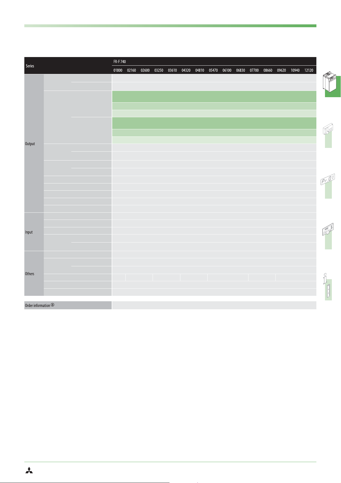
Specifications FR-F 740-01800 to -12120
SYSTEM DESCRIPTION
Rated motor
capacity
[kW]
Rated
current
햷
[A]
Output
capacity
[kVA]
Overload current
rating
Voltage
120% overlaod capacity
150% overlaod capacity
120%
overlaod
햶
capacity
150%
overlaod
capacity
120% overlaod capacity
150% overlaod capacity
120% overlaod capacity
150% overlaod capacity
햶
90 110 132 160 185 220 250 280 315 355 400 450 500 560 630
75 90 110 132 160 185 220 250 280 315 355 400 450 500 560
180
216
260
325
361
432
481
547
610
683
770
햷
I
rated
(153)
(184)
(221)
(276)
(307)
(367)
(409)
(465)
(518)
(581)
198 238 286 357 397 475 529 602 671 751 847 953 1058 1203 1333
I
max. 60 s
I
max. 3 s
216 259 312 390 433 518 577 656 732 820 924 1039 1154 1313 1454
144
180
216
260
325
361
432
481
547
햷
I
rated
(122)
(153)
(184)
(221)
(276)
(307)
(367)
(409)
173 216 259 312 390 433 518 577 656 732 820 924 1039 1154 1313
I
max. 60 s
216 270 324 390 487 541 648 721 820 915 1024 1155 1299 1443 1641
I
max. 3 s
햶
137 165 198 248 275 329 367 417 465 521 587 660 733 834 924
(465)
610
(518)
(654)
683
(581)
866
(736)
770
(654)
110 137 165 198 248 275 329 367 417 465 521 587 660 733 834
120% of rated motor capacity for 3s;110% for 1 min. (max.ambient temperature 40°C) – typical for pumps and fans
150% of rated motor capacity for 3s;120% for 1 min. (max.ambient temperature 50°C) – typical for conveyor belts and centrifuges
3-phase AC,0 V to power supply voltage
962
(818)
866
(736)
1094
(870)
962
(818)
1212
(1030)
1094
(870)
Frequency range 0.5–400 Hz
Control method V/f control,optimum excitation control or simple magnetic flux vector control
Modulation control Sine evaluated PWM,Soft PWM
Carrier frequency 0.7 kHz–6 kHz (user adjustable)
Power supply voltage 3-phase,380–500 V AC, −15% / +10%
Voltage range 323–550 V AC at 50 / 60 Hz
Power supply frequency 50 / 60 Hz ±5%
Rated input
capacity
[kVA]
120% overlaod capacity
150% overlaod capacity
햶
137 165 198 248 275 329 367 417 465 520 587 660 733 834 924
110 137 165 198 248 275 329 367 417 465 520 587 660 733 834
Cooling Fan cooling
Power loss
[kW]
120% overlaod capacity
150% overlaod capacity
햶
2.7 3.3 3.96 4.8 5.55 6.6 7.5 8.4 9.45 10.65 12.0 13.5 15.0 16.8 18.9
2.25 2.7 3.3 3.96 4.8 5.55 6.6 7.5 8.4 9.45 10.65 12.0 13.5 15.0 16.8
Frame size H J K L M N P
Inverter weight [kg] 37 50 57 72 72 110 110 220 220 220 235 235 285 285 285
Reactor weight [kg] 20 22 26 28 29 30 35 38 42 46 50 57 67 85 95
Order no.
158604 158605 158607 158608 158609 158610 158611 158612 158613 158614 158615 158616 158617 158619 158620
햲
The performance figures at the rated motor capacity are based on a motor voltage of 400 V.
햳
The overload capacity in % is the ratio of the overload current to the inverter’s rated current in the respective operating mode. For repeated duty cycles allow sufficient time for the inverter and the motor to
cool below the temperature reached at 100% load. The waiting periods can be calculated using the r.m.s. current method (I² × t), for which knowledge of the duty.
햴
The maximum output voltage cannot exceed the power supply voltage. The output voltage can be varied over the entire power supply voltage range.
햵
The rated input capacity varies depending on the impedance values on the power supply side of the inverter (including the cables and input reactor).
햶
When the load curve with 120% overload capacity is selected the maximum permitted ambient temperature is 40°C.
햷
When operating with carrier frequencies ≥ 2.5 kHz this value is reduced automatically as soon as the frequency inverter exceeds the rated output current shown in parentheses (= 85% load).
햸
When the cable bushing for the optional expansion cards is broken out the unit has an IP 00 protection rating.
햹
The suffix EC or E1 in the model designation identifies the CE versions of the frequency inverter (for the European Union). The inverter types FR-F740-02160 and above are all delivered in the E1 version as
standard (PCBs with two coats of protective varnish). The EC version (varnished PCBs) is standard for types FR-F740 00023 through 01800. The other version as always available as an option.
MITSUBISHI ELECTRIC
FR-F 740 EC/E1
13
SYSTEM DESCRIPTION
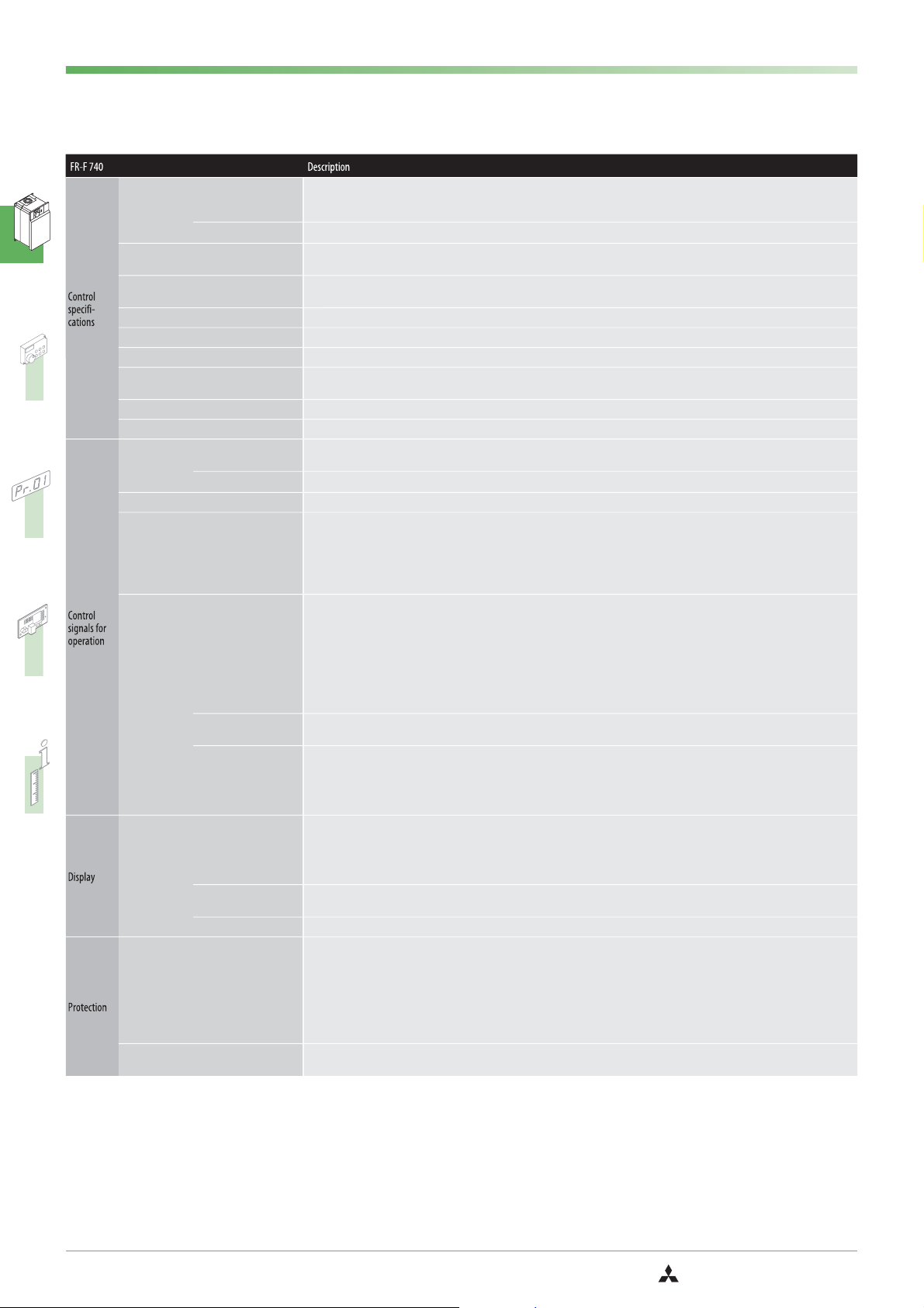
Specifications
Frequency
setting
resolution
Frequency accuracy
Voltage / frequency characteristics
Starting torque 120% (3 Hz) when set to simple magnetic flux vector control and slip compensation
Acceleration / deceleration time 0; 0.1 to 3600 s (can be set individually)
Acceleration / deceleration characteristics Linear or S-form course,user selectable
DC injection brake
Stall prevention Respones threshold 0–150%,user adjustable,also via analog input
Motor protection Electronic motor protection relay (rated current user adjustable)
Frequency
setting values
Start signal Available individually for forward rotation and reverse rotation. Start signal automatic self-holding input (3-wire input) can be selected.
Input signals
Output
signals
Control unit
display
(FR-PU04/
FR-DU07)
Protective
functions
Protection rating*
Analog input
Digital input
Analog input
Digital input
Operating state
When using the
FR-A7AY option
Pulse/analog output
Operating state
Alarm definition
Interactive guidance Operation guide/trouble shooting with a help function (FR-PU04 only)
0.015 Hz / 0–50 Hz (terminal 2, 4:0–10 V / 12 bit)
0.03 Hz / 0–50 Hz / (terminal 2, 4:0–5 V / 11 bit, 0–20 mA / 11 bit, terminal 1:−10–+10 V / 11 bit)
0.06 Hz / 0–50 Hz (terminal 1:0–±5 V / 10 bit)
0.01 Hz
±0.2% of the maximum output frequency (temperature range 25° ± 10°C) via analog input;
±0.01% of the set output frequency (via digital input)
Base frequency adjustable from 0 to 400 Hz;
selection between constant torque, variable torque or optional flexible 5-point V/f characteristics
Operating frequency (0–120 Hz),operating time ( 0–10 s) and operating voltage (0–30%) can be set individually.
The DC brake can also be activated via the digital input.
Terminal 2,4: 0–5 V DC,0–10 V DC, 0/4–20 mA
Terminal 1:0–±5 V DC, 0–±10 V DC
Operation panel or optional expansion board
Any of 12 signals can be selected using parameters 178 to 189 (input terminal function selection):
multi speed,second parameter function, terminal 4 input, JOG operation,automatic restart after instantaneous power failure, external thermal relay
input,FR-HC connection (inverter operation enable signal) and FR-HC connection (instantaneous power failure detection), control panel operation/ex
ternal interlock signal,PID control, control panel operation,control panel<->external operation,output stop, start self-holding,for ward/reverse rota
tion command,inverter reset,PTC thermistor input, PID forward/reverse operation switchover,control panel<->NET,NET<->external operation,
command source switchover
Any of 7 signals can be selected using parameter 190 to 196 (output terminal function selection):
Frequency control status,instantaneous power failure (under voltage),overload warning,output frequency detec tion,second output frequency
detection, regenerative brake with pre-alarm (01800 and above), electronic thermal relay function with pre-alarm,control panel operation
mode,inverter operation ready,output current detection, zero current detection,PID lower limit,PID upper limit, PID forward rotation/reverse rotation, commercial power supply-inverter switchover,direct mains operation motor 1-4,frequency inverter operation motor 1-4, inverter running
start command ON, deceleration at an instantaneous power failure,PID control activated, re-start, PID output suspension,life time alarm, alarm
output 3 (OFF signal), power savings average value update timing,current average monitor,alarm output2, maintenance timer alarm,remote
outputs,minor failure output, alarm output,traverse operation, open-collector outputs (5 outputs),relay outputs (2 outputs), alarm code outputs
(4 bits via open-collector)
In addition to the above operating modes parameters 313-319 (function selection for the additional 7 output terminals) can also be used to assign the following four signals: control circuit capacitor life,main circuit capacitor life,cooling fan life, inrush current limit circuit life
You can also use parameter 54 (assign analog current output) and 158 (assign analog voltage output) to assign the following displays to one or
both outputs:
output frequnecy,motor current (steady or peak), output voltage, frequency setting value,motor running speed, converter output voltage (steady
or peak), electronic thermal relay function load factor, input voltage, output voltage, load meter, reference voltage output,motor load factor,en
ergy saving effect,regenerative brake circuit duty (01800 and above),PID set point, PID process value
Output frequency,motor current (steady or peak value),output voltage, alarm indication,frequency setting, motor running speed, converter out
put voltage (steady or peak value),electronic thermal load factor,input power,output power,road meter,cumulative energization time,actual
operation time,motor load factor, watt-hours meter,power saving effect, cumulative saving power, regenerative brake circuit duty (01800 and
above),PID set point, PID process value, PID deviation monitor,I/O terminal monitor,optional input terminal monitor (FR-DU07 only),optional
output terminal monitor (FR-DU07 only),option fitting state monitor (FR-PU04 only), terminal assignment state (FR-PU04 only)
Alarm definition is displayed when the protective function is activated,the output voltage/current/frequency/cumulative energization time right
before the protection function was activated and the past 8 alarm definitions are stored.
Overcurrent cutoff (during acceleration, deceleration or at constant speed),overvoltage cutoff (during acceleration, deceleration or at constant
speed), inverter protection thermal operation,motor protection thermal operation, heatsink overheat, instantaneous power failure occurence,
under voltage,input phase failure, motor overload,output shor t circuit, ground fault overcurrent,output phase failure,external thermal relay
operation,PTC thermistor operation, option alarm,parameter error,control unit disconnection, retry count excess,CPU alarm, power supply short
for control panel,24 V DC power output short, output current detection value over,inrush resitance overheat,communication error (frequency
inverter), analog input alarm,internal circuit alarm (15 V DC power supply),fan fault, overcurrent stall prevention,overvoltage stall prevention,
electronic thermal pre-alarm,control unit stop,maintenance timer alarm (FR-DU07 only), MT-BU5 external brake module overload (01800 and
above),parameter write error,copy error,operation panel lock, parameter copy error
IP20 (FR-F 740-00023 to -00620);
IP00 (FR-F 740-00770 to -12120)
-
-
-
-
쐓
FR-DU07: IP40 (does not apply for the PU connection)
14
FR-F 740 EC/E1
MITSUBISHI ELECTRIC

General Operating Conditions
SYSTEM DESCRIPTION
Ambient temperature in operation
Storage temperature*
Ambient humidity
Altitude
Shock resistance
Vibration resistance
Ambience conditions
Certifications
Max. cable length
*
Theproductmayonlybeexposedtothefullextremesofthistemperature range for short periods (e.g. during transportation).
−10°C to +50°C (non-freezing)
For selection of the load characteristics with a 120% overload rating the max.temperature is 40°C.
−20 to +65°C
Max.90% RH (non-condensing)
Max.1000 m above NN
10 G (3 times each in 3 directions)
Max.0.6 G
For indoor use only,avoid environments containing corrosive gases,install in a dust-free location.
UL / CSA / CE / EN / Gost / CCC
2 kHz: up to 300 m for 0023,other types up to 500 m
< 5 kHz: up to 200 m for 0023,up to 300 m for 0038, other types up to 500 m
5–9 kHz: up to 100 m
≥10 kHz: up to 50 m
MITSUBISHI ELECTRIC
FR-F 740 EC/E1
15
SYSTEM DESCRIPTION
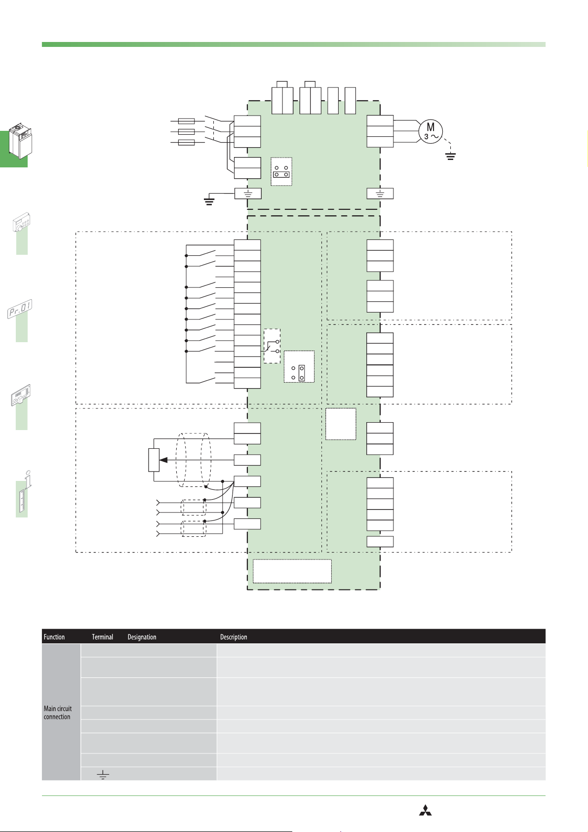
Block Diagram
24 V DC Output (max. 100 mA)
Start self-retaining selection
Multi-speed
selection
Control input signals
Current input selection / PTC
Selection of automatic restart
3phase AC
power supply
Control circuit mains
supply connection
Protective earth
Forward rotation start
Reverse rotation start
High speed
Middle speed
Low speed
Second function selection
Jog mode
Output stop
Common
Reset
L1
L2
L3
L11
L21
PC
STF
STR
STOP
RH
RM
RL
RT
JOG
MRS
AU
CS
SD
RES
P1
P/+
ON
Jumper for activating the
integrated interference
suppression filter
OFF
Main circuit
Control circuit
AU
PTC
PCT
SOURCE
PX
PR
SINK
Intermediate circuit connections
N/-
CN8*
Motor
U
V
W
A1
Relay output 1
B1
(Alarm output)
C1
A2
Relay output 2
B2
C2
Running (Motor operation)
RUN
frequency setting value/current
SU
value comparison
IPF
Instantaneous power failure
OL
Overload
FU
Frequency detection
SE
Power supply for OC outputs
*The CN8 connector is provi
ded with the inverter 01800 or
more.
Relay outputs
Open collector
-
outputs
10E
10
2
5
1
4
inputs
Frequency setting
Frequency setting
potentiometer
0,5W1kΩ
Auxiliary input
Current input
(+)
(-)
(+)
(-)
*
Input area can be set
via parameters.
Terminal Assignment of Main Circuit Terminals
L1, L2, L3
P/+, N/−
P1, P/+
PR, PX
U, V, W
L11, L21
CN8
Mains supply connection Mains power supply of the inverters (380–480 V AC,50/60 Hz); (380-500 V – 01800 and above)
External brake unit connection
Converter choke coil connection
Motor connection Voltage output of the inverter (3-phase,0 V up to power supply voltage,0,5–400 Hz)
Control circuit mains supply
connection
Ext. brake transistor control Control connection for the MT-BU5 external brake module
PE Protective earth connection of inverter
An optional external brake resistor can be connected to the terminals P and N or you can connect a optional high power factor con
verter.
An optional choke coil can be connected to the terminals P1 and P/+. The jumper on terminals P1 and P/+ must be removed when
this optional choke coil is used on frequency inverter models 01160 and below.The DC reactor supplied with the unit must be installed
on frequency inverter models 01800 and above.
Please do not remove or use terminals PR and PX or the jumper connected.
To use external power for the control circuit connect the mains power to L11/L21 (and remove jumpers L1 and L2).
+10 V
+5 V
0–5 V DC
(0–10 V DC
4–20 mA DC)*
0– 10 V DC±
(0– 5 V DC)*±
4–20 mA DC
(0–5 V DC
0–10 V DC)*
Connector/Slot for plug-in
option connection
PU Connector
AM
CA
5
TXD+
TXD-
RXD+
RXD-
SG
VCC
Analog signal output (0 – 10 V DC / 1 mA)
Analog signal output (0/4 – 20 mA)
Analog output common
Data transmission
Data reception
GND (Ground)
5 V (max. 100 mA)
RS-485
terminal
-
16
FR-F 740 EC/E1
MITSUBISHI ELECTRIC

Terminal Assignment of Signal Terminals
SYSTEM DESCRIPTION
STF Forward rotation start
STR Reverse rotation start
STOP Start self-retaining selection
RH, RM, RL Multi-speed selection
JOG Jog mode selection
RT Second parameter settings
MRS Output stop
RES RESET input
Current input selection
AU
PTC input
Automatic restart after instanta
CS
neous power failure
Reference potential (0V) for the
SD
PC terminal (24V)
PC 24 V DC output
10 E
Voltage output for
potentiometer
10
Input for frequency setting
2
value signal
Reference point for frequency
5
setting value signal
Auxiliary input for frequency set-
1
ting value signal
0–±5 (10) V DC
4 Input for setting value signal
A1, B1, C1
A2, B2, C2
Potential free
Relay output 1 (Alarm)
Potential free
Relay output 2
Signal output for motor
RUN
operation
Signal output for frequency set
ting value/current value
SU
comparison
Signal output for instantaneous
IPF
power failure
OL Signal output for overload alarm
Signal output for monitoring
FU
output frequency
Reference potential for signal
SE
outputs
CA Current output 0–20 mA
Analog output 0–10 V
AM
(1 mA)
Connection of control panel
—
(via RS485 terminal)
RS484 terminal
—
(via RS485 terminal)
The motor rotates forward, if a signal is applied to terminal STF.
The motor rotates reverse,if a signal is applied to terminal STR.
The start signals are self-retaining, if a signal is applied to terminal STOP.
Preset of 15 different output frequencies
The JOG mode is selected,if a signal is applied to terminal JOG (factory setting).The inverters FR-A 540L-G 375 k and 450 k are not
equipped with a JOG terminal.The start signals STF and STR determine the rotation direction.
A second set of parameter settings is selected, if a signal is applied to terminal RT.
The inverter lock stops the output frequency without regard to the delay time.You can select a make or break signal for the controller
inhibit function by changing parameter 17.
An activated protective circuit is reset,if a signal is applied to the terminal RES (t > 0,1 s).
The 0/4–20mA signal on terminal 4 is enabled by a signal on the AU terminal.
If you connect a PTC temperature sensor you must assign the PTC signal to the AU terminal and set the slide switch on the control cir
cuit board to the PTC position.
The inverter restarts automatically after a power failure,if a signal is applied to the terminal CS.
When “sink”control logic is selected by setting the control signal jumper a specific control function is triggered when the correspond
ing control terminal is connected to the SD terminal.
When “source”control logic is selected and you are using external 24V power you must connect the 0V of the external power supply to
terminal SD.The SD terminal is isolated from the digital electronics with optocouplers.
Internal power supply 24 V DC/0,1 A output
Output voltage 10 V DC.
Max.output current 10 mA.
Recommended potentiometer:1 kΩ, 2 W linear
Output voltage 5 V DC.
Max.output current 10 mA.
Recommended potentiometer:1 kΩ, 2 W linear
The setting value 0–10 V or 0/4–20 mA is applied to this terminal. You can switch between voltage and current setpoint values with
parameter 73.The input resistance is 10 kΩ.
Terminal 5 is the reference point for all analog setting values and for the analog output signal AM and CA.The terminal is not isolated
from the reference potential of the control circuit and must not be earthed.
An additional voltage setting value signal of 0–±5 (10) V DC can be applied to terminal 1.
The voltage range is preset to 0–±10 V DC.The input resistance is 10 kΩ.
The setting value 0/4–20 mA or 0–10 V is applied to this terminal.You can switch between voltage and current setpoint values with
parameter 73.The input resistance is 250 Ω.
The current setting value is enabled via terminal function AU.
The alarm is output via relay contacts. The block diagram shows the normal operation and voltage free status.If the protective
function is activated,the relay picks up.The maximum contact load is 200 V AC / 0.3 A or 30 V DC / 0.3 A.
Any of the available 42 output signals can be used as the output driver.
The maximum contact load is 230 V AC / 0.3 A oder 30 V DC / 0.3 A.
The output is switched low, if the inverter output frequency is equal to or higher than the starting frequency.
The output is switched high,if no frequency is output or the DC brake is in operation.
-
The SU output supports a monitoring of frequency setting value and frequency current value.The output is switched low,once the fre
quency current value (output frequency of the inverter) approaches the frequency setting value (determined by the setting value sig
nal) within a preset range of tolerance.
The output is switched low for a temporary power failure within a range of 15 ms ≤t
The OL is switched low, if the output current of the inverter exceeds the current limit preset in parameter 22 and the stall prevention is
activated.If the output current of the inverter falls below the current limit preset in parameter 22,the signal at the OL output is
switched high.
The output is switched low once the output frequency exceeds a value preset in parameter 42 (or 43).Otherwise the FU output is
switched high.
The potential that is switched via open collector outputs RUN, SU,OL, IPF and FU is connected to this terminal.
One of 18 monitoring functions can be selected,e.g. external frequency output. CA and AM output can be used simultaneously.
The functions are determined by parameters.
An amperemeter can be connected (measuring range:0–20 mA).
One of 18 monitoring functions can be selected,e.g. external frequency output. CA and AM output can be used simultaneously.
The functions are determined by parameters.
A DC voltmeter can be connected.The max. output voltage is 10 V.
Communications via RS485
I/O standard:RS485, Multi-Drop operation,4,800 – 38,400 Baud (overall length: 500 m)
Communications via RS485
I/O standard:RS485, Multi-Drop operation,300 – 38,400 Baud (overall length: 500 m)
≤ 100 ms or for under voltage.
IPF
-
-
-
-
MITSUBISHI ELECTRIC
FR-F 740 EC/E1
17

CONTROL PANELS
Built-in Operation Panel FR-DU07 (Standard)
Selected operating mode
Four-digit 7-segment display for operating pa
rameters,error codes and other functions
Operating mode selector
PU: Operation via panel keys
앫
EXT:Operation via external signals
앫
Jog shuttle for quick adjustment of the in
verter frequency and parameter settings
-
-
Setting monitoring and frequency
PU operation mod
(output frequency monitor)
8.8.8.8.
8.8.8.8.
MON
Hz
A
PU
V
REV
PU
EXT
MODE
Value change
EXT
REV
SET
P. RU N
NET
FWD
FWD
RESET
STOP
FR-DU07
Shows that the frequency inverter is in
operation
Keys for starting the inverter
FWD: Start motor forwards
앫
REV:Start motor in reverse
앫
Functions:
MODE: Switches the mode for selecting
앫
the dislay functions
SET: Key for confirming and applying
앫
parameter and frequency settings
STOP/RESET:Stop and reset functions
앫
Example
and frequency flicker
Frequency setting has been
written and completed
Setting parameters
Parameter setting mode
Output current monitor Output voltage monitor
Select parameter
Parameter clear Parameter all clear Alarm clear
Display the current setting
Parameter and a setting value
flicker alternately
18
FR-F 740 EC/E1
Parameter copy
MITSUBISHI ELECTRIC

Control Panel FR-PU04 (Option)
The control panel FR-PU04 with extended
functions is available as optional accessory.
This control panel provides a 10-key key
pad for a direct entering of numerical
values. A 4-row LC display returns opera
tional data, parameter names or status
and error messages in uncoded text.
The control panel displays text in the
following selectable languages:
English, German, French, Spanish,
Swedish, Italian, Finnish, and Japanese.
In addition to the functions* of the
standard control panel the FR-PU04 dis
plays and monitors 21 different values
and states in total.
The control unit FR-PU04 is used instead of
the standard control unit FR-DU04 and can
be replaced by this after use.
*
The parameter copy function and the parameter and alarm dis
play functions are restricted when the panel is connected to the
FR-F 740.
-
-
-
CONTROL PANELS
50
50
SET
SHIFT
READ
PARAMETER UNIT
EXT
ESC
8
5
2
WRITE
Hz
00
Hz
00
PU
9
FWD
6
REV
3
STOP
RESET
4-row LCD display (backlit)
앫 Interactive parameter setting
앫 Help function
앫 Error indication
앫 21 different displays (frequency,current,
voltage,etc.)
The desired operating mode is selected by press
ing the buttons MONITOR,SET,EXT OP or PU OP.
Keys for the selection of specific functions via
the display and the entering of numerical
values.
-
0
-
U
4
P
-
R
F
- - - STOP EXT
- - - STOP EXT
MON
HELP
7
4
1
0
-
Menu Guide to the Control Panel FR-PU04
Displaying the parameter list
Press the SET key to enter the parameter
setting menu. Then press the HELP key to
display the parameter lists. After pressing
the READ key, the according parameter va
lue will be read in.
Copying parameters
Press the SET key and then the ▲ key to
enter the copy mode. Now you find three
choices:
앬
Press the READ key to read out all
parameters from the inverter.
앬
Press the WRITE key to write
parameters to the inverter.
앬
Press the ▼ key to verify the values
stored in the control panel and the
inverter.
Display of
output
frequency
-
Display of
output
current
Display of
output
voltage
Display of
alarm history
MONI-
TOR
0 00
- - - STOP EXT
SHIFT
00000
- - -
STOP
EXT
SHIFT
0
- - -
STOP
EXT
SHIFT
Hz
A
SHIFT
0.00Hz
0.00A
- - -
V
SHIFT
0. 0V
STOP EXT
SHIFT
Others
<HELP>
SHIFT
Display of
alarms
(up to 8)
HELP
Monitor
selection
MITSUBISHI ELECTRIC
Alar m Histor y
<READ>
READ
15UVT
26UVT
3
4
7
8
FR-F 740 EC/E1
19

CONTROL PANELS
MON
PU
EXT
NET
FWD
P. R U N
Operating Modes
The inverter can alternatively be operated
via external signals or directly via the ope
ration panel FR-DU07 or the control panels
FR-PU04.
On the FR-DU07 control panel the opera
ting mode is selected by pressing the
PU/EXT key. On the FR-PU04 the EXT key
selects operation by external signals and
the PU key selects operation via the control
panel.
Operation from the control panel
The direction of rotation and frequency
setting of the inverter are controlled from
the built-in operation panel.
The setting of the output frequency is
increased or decreased via the Digital Dial.
Sample connection
-
These connections
are required for
Mains
L1
L2
L3
Start
combined
operation or
operation by
external signals.
The example below shows the operational
steps for a frequency setting with following
motor start and motor stop.
Frequency
setting
Q1
FR-F 740 EC
I
I
I
S1
S2
R1
L1
L2
L3
PC
STR
STF
10
2
5
U
V
W
Motor
Operation by external signals
The direction of rotation and frequency
setting of the inverter are controlled by
external signals. The following figure
shows the display on the built-in
operation panel FR-DU07 for forward rota
tion of the motor and a frequency of 50 Hz.
-
햲
Press the PU/EXT key
PU
EXT
햳
Set frequency with
Digital Dial
+-
햴
Press SET key to confirm
SET
햵
Press FWD to start the motor
FWD
PU
PU
PU
PU
PU
PU
PU
FWD
Hz
A
V
PU
EXT
MODE
REV
P.R U N
MON
PU
EXT
NET
FWD
FWD
REV
STOP
SET
RESET
FR-DU07
Combined operation
In addition to the operation by external
signals and the operation from the control
panel (built-in or external) the inverter can
be operated in combined operation mode.
앬
Setting value preset from the control
panel and external starting signal.
앬
External setting value signal and star
ting signal from the control panel.
-
햶
Stop motor
20
STOP
RESET
FR-F 740 EC/E1
PU
PU
FWD
MITSUBISHI ELECTRIC

VFD Setup Software
CONTROL PANELS
The VFD Setup Software is a powerful
tool for the operation of your frequency in
verter. The software (version 2.4) is MS
Windows 95/98/ME/XP and NT/2000 com
patible, and therefore allows the inverter
operation via any conventional personal
computer. Several frequency inverters can
be set up, operated, and monitored simul
taneously across a network or via a perso
nal computer or notebook. The software is
designed for all frequency inverters of the
MITSUBISHI FR-S 500, FR-E 500, FR-A 500,
FR-F 500 and FR-F 700* series.
The connection between personal compu
ter and inverter is established either
via an RS485 network or directly via an
SC-FR PC adapter cable available separately.
MITSUBISHI
700
FREQROL-F
ock
h
rics
t
.
e
ofinjuryand elec
k
!
ionsbeforeus
t
ruc
DANGER:Ris
t
fetyins
a
hes
t
ver.
o
ngthisc
i
Readthemanual and follow
pplyandwait 10 minutes before remov
u
latefroms
o
Is
ion
t
nnec
o
reproperearth c
u
Ens
offire
k
.
e
!
rfac
u
CAUTION:Ris
ibles
t
mbus
o
Mounttheinverter on a non-c
FR–F740–2.2K
400V
Parameter setting
-
-
-
-
-
Display and monitor
Benefits
앬
System settings
Due to the network capabilities of the
inverter up to 32 frequency inverters
can be operated simultaneously.
앬
Parameter settings
By means of overall and function rela
ted overviews different parameters can
be adjusted easily.
앬
Display functions
The comprehensible display functions
enable data, analog, oscillograph, and
alarm displays.
앬
Diagnostis
The analysis of the inverter status
provides a thorough error correction.
앬
Test operation
The test operation provides a simulati
on of the operation and adjustment via
the auto-tuning function.
앬
File management
Parameters can be saved on the
personal computer and printed out.
앬
Help
The extensive online help provides
support concerning all questions
regarding settings and operation.
-
Test operation
-
MITSUBISHI ELECTRIC
*
The FR-F700 is supported by Version 3.1 and above
(available from January 2005)
FR-F 740 EC/E1
21

PARAMETER
Parameter Overview
0
Torque boost
1
Maximum frequency
2
Minimum frequency
3
Base frequency
4
1. Multi-speed setting (high speed)
5
2. Multi-speed setting (middle speed)
6
3. Multi-speed setting (low speed)
7
Acceleration time
8
Deceleration time
9
Electronic thermal O/L relay
10
DC injection brake operation frequency
11
DC injection brake operation time
12
DC injection brake operation voltage
13
Starting frequency
14
Load pattern selection
15
JOG frequency
16
JOG acceleration/deceleration time
17
MRS input selection
18
High speed maximum frequency
19
Base frequency voltage
20
Acceleration/deceleration reference frequency
21
Acceleration/deceleration time increments
22
Stall prevention operation level
Stall prevention operation level compensation factor at double
23
speed
24
Multi-speed setting (speed 4)
25
Multi-speed setting (speed 5)
26
Multi-speed setting (speed 6)
27
Multi-speed setting (speed 7)
28
Multi-speed input compensation selection
29
Acceleration/deceleration pattern selection
30
Regenerative function selection
31
Frequency jump 1A
32
Frequency jump 1B
33
Frequency jump 2A
34
Frequency jump 2B
35
Frequency jump 3A
36
Frequency jump 3B
37
Speed display
41
Up-to-frequency sensitivity
42
Output frequency detection
43
Output frequency detection for reverse rotation
44
2nd Acceleration/deceleration time
45
2nd Deceleration time
46
2nd Torque boost
47
2nd V/f characteristics (base frequency)
48
2nd Stall prevention operation current
49
2nd Stall prevention operation frequency
50
2nd Output frequency detection
51
2nd Electronic thermal O/L relay
햲
햲
햲
햲
햲
햲
0–30% 6/4/3/2/1.5/1%
0–120 Hz 120 / 60 Hz
햳
햳
0–120 Hz 0 Hz
0–400 Hz 50 Hz
햲
햲
0–400 Hz 50 Hz
0–400 Hz 30 Hz
0–400 Hz 10 Hz
0–360 s / 0–3600 s 5 s / 15 s
0–360 s / 0–3600 s 10 s / 30 s
0–500 A / 0–3600 A
햳
햳
햳
Rated current
0–120 Hz / 9999 3 Hz
0–10 s / 8888 0.5 s
0–30% 4/ 2 / 1%
햳
0–60 Hz 0.5 Hz
0/1 1
0–400 Hz 5 Hz
0–360 s / 0–3600 s 0.5 s
0, 2 0
120–400 Hz 120 / 60 Hz
햳
0–1000 V / 8888 / 9999 8888
1–400 Hz 50 Hz
0/1 0
0–150% / 9999 /
0–120% / 9999
0–150% / 9999/
0–120% / 9999
햳
햳
120% /
110%
9999
햳
0–400 Hz / 9999 9999
0–400 Hz / 9999 9999
0–400 Hz / 9999 9999
0–400 Hz / 9999 9999
0/1 0
0/1/2/3 0
0/2/
0/1/2
햳
0
0–400 Hz / 9999 9999
0–400 Hz / 9999 9999
0–400 Hz / 9999 9999
0–400 Hz / 9999 9999
0–400 Hz / 9999 9999
0–400 Hz / 9999 9999
0 / 1–9998 0
0–100% 10%
0–400 Hz 6 Hz
0–400 Hz / 9999 9999
0–360 s / 0–3600 s 5 s
0–360 s / 0–3600 s / 9999 9999
0–30% / 9999 9999
0–400 Hz / 9999 9999
0–150% /
0–120%
햳
120% /
110%
햳
0–400 Hz / 9999 0 Hz
0–400 Hz 30 Hz
0–500 A / 9999 /
0–3600 A / 9999
햳
9999
22
FR-F 740 EC/E1
MITSUBISHI ELECTRIC

PARAMETER
52
DU/PU main display data selection
54
CA terminal function selection
55
Frequency monitoring reference
56
Current monitoring reference
57
Restart coasting time
58
Restart cushion time
59
Remote function selection
60
Energy saving control selection
65
Retry selection
66
Stall prevention operation reduction starting frequency
67
Number of retries at alarm occurrence
68
Retry waiting time
69
Retry count display erase
70
Special regenerative brake duty
71
Applied motor
72
PWM frequency selection
73
Analog input selection
74
Input filter time constant
75
Reset selection/disconnected PU detection/PU stop selection
76
Alarm code output selection
77
Parameter write selection
78
Reverse rotation prevention selection
79
Operation mode selection
80
Motor capacity (simple magnetic flux vector control)
90
Motor constant (R1)
100
V/f1 (1st frequency)
101
V/f1 (1st frequency voltage)
102
V/f2 (2nd frequency)
103
V/f2 (2nd frequency voltage)
104
V/f3 (3rd frequency)
105
V/f3 (3rd frequency voltage)
106
V/f4 (4th frequency)
107
V/f4 (4th frequency voltage)
108
V/f5 (5th frequency)
109
V/f5 (5th frequency voltage)
117
PU communication station
118
PU communication speed
119
PU communication stop bit length
120
PU communication parity check
121
Number of PU communication retries
122
PU communication check time interval
123
PU communication waiting time setting
124
PU communication CR/LF presence/absence selection
125
Terminal 2 frequency setting gain frequency
126
Terminal 4 frequency setting gain frequency
127
PID control automatic switchover frequency
128
PID action selection
129
PID proportional band
햲
햲
햲
햵
햲
햲
햲
햲
0/5/6/8–14/17/20/23/
24 / 25 / 50–57 / 100
햴
1–3/5/6/8–14/17/21/24/50/52/53
0
햴
1
0–400 Hz 50 Hz
0–500 A /
햳
0–3600 A
0 / 0.1–5 s / 9999 /
0 / 0.1–30 s / 9999
Rated current
9999
0–60 s 1 s
0/1/2/3 0
0/4/9 0
0–5 0
0–400 Hz 50 Hz
0–10 / 101–110 0
0–10 s 1 s
00
0–10% 0%
0/1/2/20 0
0–15 /
0–6 / 25
햳
2
0–7 / 10–17 1
0–8 1
햲
0–3 / 14–17 / 100–103 / 114–117
햶
14
0/1/2 0
0/1/2 0
0/1/2 0
0–4/6/7 0
0.4–55 kW / 9999 /
0–3600 kW / 9999
0.4–50 Ω / 9999 /
0–400 mΩ / 9999
햳
햳
9999
9999
0–400 Hz / 9999 9999
0–1000 V 0
0–400 Hz / 9999 9999
0–1000 V 0
0–400 Hz / 9999 9999
0–1000 V 0
0–400 Hz / 9999 9999
0–1000 V 0
0–400 Hz / 9999 9999
0–1000 V 0
0–31 0
48 / 96 / 192 / 384 192
0/1datalength8;10/11datalengthe7 1
0/1/2 2
0–10 / 9999 1
0–999.8 s / 9999 9999
0–150 ms / 9999 9999
0/1/2 1
0–400 Hz 50 Hz
0–400 Hz 50 Hz
0–400 Hz / 9999 9999
10 / 11 / 20 / 21 / 50 / 51 / 60 / 61 10
0.1–1000% / 9999 100%
MITSUBISHI ELECTRIC
FR-F 740 EC/E1
23

PARAMETER
130
PID integral time
131
PID upper limit
132
PID lower limit
133
PID action set point
134
PID differential time
135
Power-supply switchover sequence output terminal selection
136
MC switchover interlock time
137
Waiting time at a start
Commercial power-supply operation switchover selection at an
138
alarm
Automatic switchover frequency between inverter and commercial
139
power-supply operation
140
Backlash acceleration stopping frequency
141
Backlash acceleration stopping time
142
Backlash deceleration stopping frequency
143
Backlash deceleration stopping time
144
Speed setting switchover
145
PU display language selection
148
Stall prevention level at 0 V input
149
Stall prevention level at 10 V input
150
Output current detection level
151
Output current detection signal delay time
152
Zero current detection level
153
Zero current detection time
154
Voltage reduction selection during stall prevention operation
155
RT signal reflection time selection
156
Stall prevention operation selection
157
OL signal output timer
158
AM terminal function selection
Automatic switchover ON range between commercial power-sup
159
ply and inverter operation
160
User group read selection
161
Frequency setting/key lock operation selection
162
Automatic restart after instantaneous power failure selection
163
First cushion time for restart
164
First cushion voltage for restart
165
Stall prevention operation level for restart
166
Output current detection signal retention time
167
Output current detection operation selection
168
Parameter for manufacturer setting. Do not make setting!
169 — —
170
Cumulative power meter clear
171
Operation hour meter clear
172
User group registered display/batch clear
173
User group registration
174
User group clear
178
STF terminal function selection
179
STR terminal function selection
180
RL terminal function selection
181
RM terminal function selection
182
RH terminal function selection
183
RT terminal function selection
햲
햲
햲
0 / 2 / 4 / 6 / 8 / 10 / 102 / 104 / 106 / 108 / 110 4
햲
햲
1–3/5/6/8–14/17/21/24/50/52/53
-
0.1–3600 s / 9999 1 s
0–100% / 9999 9999
0–100% / 9999 9999
0–100% 0%
0.01–10.00 s / 9999 9999
0/1 0
0–100 s 1 s
0–100 s 0.5 s
0/1 0
0–60 Hz / 9999 9999
0–400 Hz 1 Hz
0–360 s 0.5 s
0–400 Hz 1 Hz
0–360 s 0.5 s
0–7 1
0–120% 110%
0–120% 120%
0–120% 110%
0–10 s 0 s
0–200% 5%
0–1 s 0,5 s
0/1 1
0/10 0
0–31 / 100 / 101 0
0–25 s / 9999 0
0–10 Hz / 9999 9999
0 / 1 / 9999 9999
0/1/10/11 0
0/1/10/11 0
0–20 s 0 s
0–100% 0%
0–120% 110%
0–10 s / 9999 0.1 s
0/1 0
——
0 / 10 / 9999 9999
0 / 9999 9999
9999 (0–16) 0
0–999 / 9999 9999
0–999 / 9999 9999
0–8 / 10–12 / 14 / 16 / 24 / 25 /
37 / 60 / 62 / 64–67 / 9999
0–8 / 10–12 / 14 / 16 / 24 / 25/
37 / 61 / 62 / 64–67 / 9999
0–8 / 10–14 / 16 / 24 / 25 / 37 /
62 / 64–67 / 9999
햴
1
60
61
0
1
2
3
24
FR-F 740 EC/E1
MITSUBISHI ELECTRIC

PARAMETER
184
AU terminal function selection
185
JOG terminal function selection
186
CS terminal function selection
187
MRS terminal function selection
188
STOP terminal function selection
189
RES terminal function selection
190
RUN terminal function selection
191
SU terminal function selection
192
IPF terminal function selection
193
OL terminal function selection
194
FU terminal function selection
195
ABC1 terminal function selection
196
ABC2 terminal function selection
232
Multi-speed setting (speed 8)
233
Multi-speed setting (speed 9)
234
Multi-speed setting (speed 10)
235
Multi-speed setting (speed 11)
236
Multi-speed setting (speed 12)
237
Multi-speed setting (speed 13)
238
Multi-speed setting (speed 14)
239
Multi-speed setting (speed 15)
240
Soft-PWM operation selection
241
Analog input display unit switchover
242
Terminal 1 added compensation amount (terminal 2)
243
Terminal 1 added compensation amount (terminal 4)
244
Cooling fan operation selection
245
Rated slip
246
Slip compensation time constant
247
Constant-output region slip compensation selection
250
Stop selection
251
Output phase failure protection selection
252
Override bias
253
Override gain
255
Life alarm status display
256
Inrush current suppression circuit life display
257
Control circuit capacitor life display
258
Main circuit capacitor life display
259
Main circuit capacitor life measuring
260
PWM frequency automatic switchover
261
Power failure stop selection
262
Subtracted frequency at deceleration start
263
Subtraction starting frequency
264
Power-failure deceleration time 1
265
Power-failure deceleration time 2
266
Power failure deceleration time switchover frequency
267
Terminal 4 input selection
268
Monitor decimal digits selection
269
Parameter for manufacturer setting. Do not make setting!
331
RS-485 communication station
햲
햲
0–8 / 10–14 / 16 / 24 / 25 / 37 / 62–67 / 9999 4
5
6
0–8 / 10–14 / 16 / 24 / 25 /
37 / 62 / 64–67 / 9999
24
25
62
0
0–5 / 7 / 8 / 10–19 / 25 / 26 / 45–47 / 64 /
70–78 / 90–96 / 98 / 99 / 100–105 / 107 /
108 / 110–116 / 125 / 126 / 145–147 /
164 / 170 / 190–196 / 198 / 199 / 9999
햷
1
2
3
4
0–5 / 7 / 8 / 10–19 / 25 / 26 / 45–47 / 64 /
70–78 / 90 / 91 / 94–96 / 98 / 99 / 100–105 /
107 / 108 / 110–116 / 125 / 126 / 145–147 /
164 / 170 / 190 / 191 / 194–196 /
198 / 199 / 9999
햷
99
9999
0–400 Hz / 9999 9999
0–400 Hz / 9999 9999
햲
햲
햲
햲
햲
햲
햲
햲
0–400 Hz / 9999 9999
0–400 Hz / 9999 9999
0–400 Hz / 9999 9999
0–400 Hz / 9999 9999
0–400 Hz / 9999 9999
0–400 Hz / 9999 9999
0/1 1
0/1 0
0–100% 100%
0–100% 75%
0/1 0
0–50% / 9999 9999
0,01–10 s 0.5 s
0 / 9999 9999
0–100 s / 1000–1100 s / 8888 / 9999 9999
0/1 1
0–200% 50%
0–200% 150%
(0–15) 0
(0–100%) 100%
(0–100%) 100%
(0–100%) 100%
0/1 0
0/1 1
0/1/2 0
0–20 Hz 3 Hz
0–120 Hz / 9999 50 Hz
0–360 s / 0–3600 s 5 s
0–360 s / 0–3600 s / 9999 9999
0–400 Hz 50 Hz
0/1/2 0
햲
0 / 1 / 9999 9999
——
0–31
(0–247)
0
MITSUBISHI ELECTRIC
FR-F 740 EC/E1
25

PARAMETER
332
RS-485 communication speed
333
RS-485 communication stop bit length
334
RS-485 communication parity check selection
335
RS-485 communication number of retries
336
RS-485 communication check time interval
337
RS-485 communication waiting time setting
338
Communication operation command source
339
Communication speed command source
340
Communication startup mode selection
341
RS-485 communication CR/LF selection
342
Communication E
343
Communication error count
495
Remote output selection
496
Remote output data 1
497
Remote output data 2
503
Maintenance timer
504
Maintenance timer alarm output set time
549
Protocol selection
550
NET mode operation command source selection
551
PU mode operation command source selection
555
Current average time
556
Data output mask time
557
Current average value monitor signal output reference current
563
Energization time carrying-over times
564
Operating time carrying-over times
570
Multiple rating setting
571
Holding time at a start
573
4 mA Input check selection
575
Output interruption detection time
576
Output interruption detection level
577
Output interruption release level
578
Auxiliary motor operation selection
579
Motor switchover selection
580
MC switching interlock time
581
Start waiting time
582
Auxiliary motor connection-time deceleration time
583
Auxiliary motor disconnection-time acceleration time
584
Auxiliary motor 1 starting frequency
585
Auxiliary motor 2 starting frequency
586
Auxiliary motor 3 starting frequency
587
Auxiliary motor 1 stopping frequency
588
Auxiliary motor 2 stopping frequency
589
Auxiliary motor 3 stopping frequency
590
Auxiliary motor start detection time
591
Auxiliary motor stop detection time
592
Traverse function selection
593
Maximum amplitude amount
594
Amplitude compensation amount during deceleration
595
Amplitude compensation amount during acceleration
596
Amplitude acceleration time
597
Amplitude deceleration time
2
PROM write selection
햲
햲
햲
햲
3 / 6 / 12 / 24 / 48 / 96 / 192 / 384 96
0/1/10/11 1
0/1/2 2
0–10 / 9999 1
0–999.8 s / 9999 0
0–150 ms / 9999 9999
0/1 0
0/1 0
0/1/2/10/12 0
0/1/2 1
0/1 0
—0
0/1 0
0–4095 0
0–4095 0
0 (1–9998) 0
0–9998 / 9999 9999
0/1 0
0 / 1 / 9999 9999
1/2 2
0.1–1.0 s 1 s
00,0–20,0 s 0 s
햲
0–500 A / 0–3600 A
햳
Rated inverter current
(0–65535) 0
(0–65535) 0
0/1 1
0.0–10.0 s / 9999 9999
1 / 9999 9999
0–3600 s / 9999 1 s
0–400 Hz 0 Hz
900–1100% 1000%
0/1/2/3 0
0/1/2/3 0
0–100 s 1 s
0–100 s 1 s
0–3600 s 1 s
0–3600 s / 9999 1 s
0–400 Hz 50 Hz
0–400 Hz 50 Hz
0–400 Hz 50 Hz
0–400 Hz 0 Hz
0–400 Hz 0 Hz
0–400 Hz 0 Hz
0–3600 s 5 s
0–3600 s 5 s
0/1/2 0
0–25% 10%
0–50% 10%
0–50% 10%
0.1–3600 s 5 s
0.1–3600 s 5 s
26
FR-F 740 EC/E1
MITSUBISHI ELECTRIC

PARAMETER
611
867
869
872
882
883
884
885
886
888
889
891
892
893
894
895
896
897
898
899
C0 (900)
C1 (901)
C2 (902)
C3 (902)
125 (903)
C4 (903)
C5 (904)
C6 (904)
126 (905)
C7 (905)
C8 (930)
C9 (930)
C10 (931)
C11 (931)
989
990
991
PR.CL
ALLC
Er.CL
PCPY
Acceleration time at a restart
AM output filter
Current output filter
Input phase failure protection selection
Regeneration avoidance operation selection
Regeneration avoidance operation level
Regeneration avoidance at deceleration detection sensitivity
Regeneration avoidance compensation frequency limit value
Regeneration avoidance voltage gain
Free parameter 1
Free parameter 2
Cumulative power monitor digit shifted times
Load factor
Energy saving monitor reference (motor capacity)
햲
햲
햲
햲
햲
Control selection during commercial power-supply operation
Power saving rate reference value
Power unit cost
햲
Power saving monitor average time
Power saving cumulative monitor clear
Operation time rate (estimated value)
CA terminal calibration
AM terminal calibration
햲
햲
햲
햲
햲
햲
Terminal 2 frequency setting bias frequency
Terminal 2 frequency setting bias
Terminal 2 frequency setting gain frequency
Terminal 2 frequency setting gain
Terminal 4 frequency setting bias frequency
Terminal 4 frequency setting bias
Terminal 4 frequency setting gain frequency
Terminal 4 frequency setting gain
Current output bias signal
Current output bias current
Current output gain signal
Current output gain current
Parameter copy alarm release
PU buzzer control
PU contrast adjustment
햲
햲
Parameter clear
All parameter clear
Alarm history clear
Parameter copy
0–3600 s / 9999 5 s / 15 s
햳
0–5 s 0.01 s
0–5 s 0,02 s
0/1 0
0/1 0
300–800 V 760 V DC
0–5 0
0–10 Hz / 9999 6 Hz
0–200% 100%
0–9999 9999
0–9999 9999
0–4 / 9999 9999
30–150% 100%
0.1–55 kW / 0–3600 kW
햲
0/1/2/3 0
햳
Motor capacity at 120% / 150% overload
capacity
0 / 1 / 9999 9999
0–500 / 9999 9999
0 / 1–1000 h / 9999 9999
0 / 1 / 10 / 9999 9999
0–100% / 9999 9999
Calibration range —
Calibration range —
0–400 Hz 0 Hz
0–300% 0%
0–400 Hz 0 Hz
0–300% 100%
0–400 Hz 0 Hz
0–300% 20%
0–400 Hz 50 Hz
0–300% 100%
0–100% 0%
0–100% 0%
0–100% 100%
0–100% 100%
10 / 100
햳
10 / 100
햳
0/1 1
0–63 58
0/1 0
0/1 0
0/1 0
0/1/2/3 0
Notes:
햲
These parameters can be changed during operation if parameter 77 is set to 0 (factory setting).
햳
The possible setting values depend on the capacity class of the inverter.
햴
A setting of 9 is possible on models 01800 and above.
햵
This setting is possible on models 01800 and above.
햶
Setting of 100 to 103, 114 to 117 are possible on models 01800 and above.
햷
Setting of 7 and 107 are possible on models 01800 and above.
MITSUBISHI ELECTRIC
FR-F 740 EC/E1
27

PROTECTIVE FUNCTIONS
Protective Functions Overview
The frequency inverter FR-F 740 provides a
large number of protective functions that
protect the drive and the inverter against
damage in case of any malfunction.
햲
HOLD
Er1
Er2
Er3
Er4
rE1
rE2
rE3
rE4
MT
햲
햲
햲
햲
햲
햲
햲
햲
Err.
OL
oL
rb
PS
TH
햲
CP
FN
Operation panel lock Operation lock mode ist set.
Write disable error
Write error
This error occurs when a write operation is attempted with Pr. 77 = 1,the frequency jump ranges
overlap,the ranges for the flexible 5-point V/f characteristic overlap or no communication is possi
ble between the control panel and the frequency inverter.
This error occurs when a write operation is attempted with the inverter in operation when the value
of Pr.77 <> 2 and an STF or STR start signal is active.
Calibration error Analog input bias and gain calibration values are too close. Check the parameter C3,C4, C6 and C7
Mode designation error This error occurs when you try to set a parameter in NET mode when PR.77 <> 2.
Parameter read error An error occurred in the E²PROM on the operation panel side during parameter copy reading.
Parameter write error An error occurred in the E²PROM on the operation panel side during parameter copy writing.
Parameter verification
error
Data on the operation panel side and inverter side are different.An error occurred in the E²PROM on
the operation panel side during parameter verification.
Model error A different model was used for parameter write and verification during parameter copy.
Error
Overcurrent during
acceleration
Overcurrent during con
stant speed operation
Overcurrent during
deceleration
Overvoltage during
deceleration
Regenerative brake
prealarm
Inverter was stopped via
control panel
Electronic thermal relay
function prealarm
Maintenance signal
output
Parameter copy
The RESET signal is active or there is an error in the communication between the frequency inverter
and the control panel.
If a current of more than 110%
stops the increase in frequency until the overload current reduces to prevent the inverter from re
sulting in overcurrent shut-off.When the overload current has reduced below 110%,this function
increases the frequency again.
If a current of more than 110%
ers the frequency until the overload current reduces to prevent overcurrent shut-off.When the over
load current has reduced below 110%,this function increases the frequency up to the set value.
If a current of more than 110%
stops the decrease in frequency until the overload current reduces to prevent theinverter from re
sulting in overcurrent shut-off.When the overload current has reduced below 110%,this function
decreases the frequency again.
If the regenerative energy of the motor increases too much to exceed the brake capability,this func
tion stops the decrease in frequency to prevent overvoltage shut-off.As soon as the regenerative
energy has reduced,deceleration resumes.
Too much energy is being fed into the brake resistor (model 01800 and above).
STOP key on the control panel was pressed during external operating mode. Check the parameter 77.
The prealarm of the electronic motor protection switch has activated. The load or number of work cycles is too high.
The cumulated operating time has reached the preset value.
Attempt to perform a copy operation from a frequency inverter model 01160 or lower to a model
01800 or higher.
Fan fault The cooling fan is not operating as set in Pr.244. Replace the cooling fan.
If an error occurs, the output of the inverter
is suspended and the control panel
returns an error message.
햳
of the rated inverter current flows in the motor,this function
햳
of the rated inverter current flows in the motor,this function low
햳
of the rated inverter current flows in the motor,this function
Press and hold the MODE key for 2 s to enable
the operation panel.
Check the setting of Pr.77, Pr.31 to 36 Pr. 100 to
109 and the connection of the operation panel
and inverter.
Check the setting of Pr.77. The frequency
inverter must be in stop mode.
Check the setting of Pr.77. Set the operating
mode to operation via control panel.
Repeat the copy operation.Check the control
panel connections.Please contact your nearest
MITSUBISHI ELECTRIC representative if the error
occurs repeatedly.
Repeat the copy operation with the inverter
stopped.Check the control panel connections.
Please contact your nearest MITSUBISHI ELECTRIC representative if the error occurs repeatedly.
Press the SET key to continue verification.Check
the control panel connections.Please contact
your nearest MITSUBISHI ELECTRIC representative if the error occurs repeatedly.
Use the same model for parameter copy and
verification.
Deactivated the RESET signal.Check the con
nections between the control panel and the
frequency inverter.
-
Increase the stall prevention operation level
with Pr.22 "stall prevention operation level"
or disable stall prevention with Pr.156 "stall
prevention operation selection".
-
Increase the deceleration time with Pr.8 "decel
eration time".
Increase the deceleration time.Check the Pr.30
and 70 values.
The value in Pr.503 is larger than the setting of
Pr.504.
Reset parameters 9,30, 51, 52,54, 56 57,61, 70,
72, 80,90, 158,190-196 and 893.
-
-
28
FR-F 740 EC/E1
MITSUBISHI ELECTRIC

PROTECTIVE FUNCTIONS
E.OC1
E.OC2
E.OC3
E.OV1
E.OV2
E.OV3
E.THM
E.THT
E.FIN
E.IPF
E.UVT
E.ILF
E.OLT
E.GF
E.LF
E.OHT
E.PTC
E.OPT
E.OP1
E.PE
E.PE2
Overcurrent 1
(acceleration)
Overcurrent 2
(const.speed)
Overcurrent 3
(deceleration)
Overvoltage 1
(acceleration)
Overvoltage 2
(constant speed)
Overvoltage 3
(deceleration)
Motor overload shutoff
Inverter overload shutoff
Fin overheat
Instantaneous
power failure protection
Undervoltage protection
햲
햲
E.1
햲
Input phase failure Open phase at power supply input.
Stall prevention
overload
Ground failure An overcurrentoccureddue toa ground failure upon the inverteroutput (load). Check load connections (motor circuit).
Output phase failure
protection
Activation of an external
motor protection relay
(thermal contact)
PTC thermistor operation
Option alarm
Option slot alarm The protective function is activated for a fault (e.g.transmission error) of an internal optional unit. Check the function settings of the optional unit.
Option alarm (e.g. con
nection or contact fault)
Parameter storage device
alarm (control circuit
board)
Parameter storage device
alarm (main circuit board)
The output current of the inverter has reached or exceeded 200% of the rated current during the ac
celeration,deceleration, or at constant speed.
The converter voltage has increased highly due to regenerative energy.The overvoltage limit was
exceeded during acceleration, deceleration, or at constant speed.
The electronic overload protection for the motor or inverter was activated.
The electronic motor protection switch continually detects the motor current and the output frequency of the inverter.If a self-cooling motor operates over a long period at low speed but high
torque,the motor is thermally overloaded and the protective function is activated.
If several motors are operated by one inverter the motor protection switch will not operate properly.
In this case deactivate the motor protection and replace it by external protection switches.
In case of an overheating of the heat sink the temperature sensor responds and the inverter is
stopped.
The output of the inverter is suspended and the alarm message returned,if the power supply fails
for more than 15 ms.If the power supply fails for more than 100 ms,the inverter shuts down completely.In this case after restoring the power supply the inverter is in the power ON state.If the
power failure stays below 15 ms,the operation is proceeded normally.
The input voltage of the inverter has fallen below the minimum value.The protective function is ac
tivated,if the input voltage falls below the minimum value.
A long lasting excess of the current limit (OL display) shut down the inverter.
One of the phases (U, V, W) is not connected. Check the connections.
An external motor protective switch was activated.
If an external motor protective switch for thermal monitoring is used,this switch can activate the
protective function of the inverter.
The frequency inverter has shut down because the resistance of the PTC thermistor has exceeded
the permitted 500Ω–4kΩ range for 10s.
This error is displayed when an FR-HC,MT-HC or FR-CV external optional unit is installed and the
power supply is still connected via terminals L1,L2 and L3.
-
This protective function is activated when an error (e.g.a contact fault) is registered in the installed
optional unit.
Error on access of the data memory of the inverter.
Error on access of the data memory of the inverter.
The cause for the activation of the protective
function is a short circuit or a ground fault
across the main outputs,an exceeding moment
of inertia of the load (GD
tion / deceleration time presets, restart during a
motor idling phase,operation of a motor with
an exceeding capacity.
Overheating due to insufficient cooling (defec
tive cooling fan or choked heat sink).
In most cases the protective function is acti
vated due to a too short deceleration time
preset or a regenerative overload.
Remedy by increasing the deceleration time of
connecting an external brake unit.
An overvoltage in the mains power supply
activates this protective function as well.
Decrease the motor load to avoid an activation.
Check whether the performance range of the
motor and inverter correspond.
Check ambient temperature.
Check the power supply.
An undervoltage can occur,if the capacity of
-
the mains transformer is not sufficient or if a
high capacity motor is turned ON connected to
the same mains supply circuit.
Check the power supply connections and the
mains fuse!
Reduce the load.
Check the preset values for the current limit
(parameter 22) and the stall prevention
selection (parameter 156).
Leitungen und Anschlüsse am Eingang prüfen
Check the PTC connection.Check motor opera
tion under load.Check setting of Pr.184.
Check the setting of Pr.30 and the installation
and connections of the optional unit.
Check the connections of the optional unit.
Check for electromagnetic interference.
Please contact your nearest MITSUBISHI
ELECTRIC representative if the error occurs
repeatedly.
Please contact your nearest MITSUBISHI
ELECTRIC representative if the error occurs
repeatedly.
2
), too short accelera
-
-
-
-
MITSUBISHI ELECTRIC
FR-F 740 EC/E1
29

PROTECTIVE FUNCTIONS
E.PUE
E.RET
E.CPU
E. 6
E. 7
E.CTE
E.P24
E.CdO
E.IOH
E.SEr
E.AIE
E.BE
E.13
PU disconnection
Retry count excess
CPU error
CPU error
CPU error
Operation panel/RS-485
terminal power supply
short circuit
24 V DC power supply
short circuit
햲
햲
햲
햲
햲
Output current detection
value exceeded
Inrush resistance overheat This error occurs when the inrush current limiter overheats.
Communication error
(inverter)
Analog input error
Brake transistor alarm
detection/Internal circuit
error
Internal circuit error Error in the internal circuit of the device.
A connection error between inverter and control panel occurred during operation.This alarm is only
returned,if parameter 75 is set to “2", ”3",“16", or ”17".
After activation of a protective function the inverter failed to be restarted automatically within the
number of retries specified in parameter 67.
Communication error with the built-in CPU
The operation panel power supply is shorted.
Check the connection of control panel.
Remedy the actual cause of the originary
protective function.
Please contact your nearest MITSUBISHI
ELECTRIC representative if the error occurs
repeatedly.
Locate and correct the short.Check the control
panel and the connection cable.
The 24 V DC power output from the PC terminal is shorted. Locate and correct the short.
The max.output current set in Pr.150 has been exceeded. Check the setting of Pr.150, 151,166 and 167.
Reduce the inrush current.Avoid switching op
erations during the switch-on phase.
Communication error at the RS-485 port. Check the wiring.
Invalid signal (>30 mA or >7.5 V) at the analog input programmed with the current setting value
function.
For the 01800 or more:
Inverter output stop if an alarm occurs in the brake circuit, e.g.damaged brake transistor.
For 01160 or less:
Internal circuit error
Check the setting of Pr.73 and Pr.267.
Reduce the load inertia.
Check the frequency of using the brake and the
brake transistor.
Please contact your nearest MITSUBISHI
ELECTRIC representative if the error occurs
repeatedly.
-
햲
If when employing the control panel FR-PU04 one of the errors HOLD, Er1 to 4, rE1 to 4, MT, E.ILF, E.PTC, E.PE2, E.CDO, E.IOH, E.SER, E.AIE, E.13 occurs, then Fault 14 will be displayed.
햳
When the overload capacity is 150% the limit is 120%.
30
FR-F 740 EC/E1
MITSUBISHI ELECTRIC

Resetting Methods
PROTECTIVE FUNCTIONS
When a protective function is activated,
the output of the inverter is switched off.
The motor coasts to a halt. The output
remains switched off until the error cause
is eliminated and the inverter reset.
The inverter can be reset following four
different methods:
Switch the power supply OFF and ON
앬
again.
Switch the reset signal ON for at least
앬
0.1 s.
Press the RESET key on the control
앬
panel.
Use the automatic restart function (Pr.
앬
65, Pr. 67-69)
If the reset signal is ON continuously, the
operation panel FR-DU07 returns an error
message while the control unit FR-PU04
indicates that the reset procedure is in
progress.
When a protective function is activated,
the operation panel FR-DU07 returns an er
ror code as listed in the table above.
The control panel FR-PU04 returns error
messages in clear.
If on occurrence of an error the input
protection contactor is toggled the error
message cannot be retained, since there is
no power supply for the control circuit.
If the error message is intended to be
retained in spite of an activation of the pro
tectve contactor, the control circuit has to
be supplied by a separate power supply.
Separate power supply for the
control circuit
The figure on the right shows the connecti
on of the separate 380-480 V AC
(-15%/+10%) power supply for the control
circuit. The current consumption is 2 A.
Prior to the connection remove the two
short bars upon L11 and L21 on the
inverter.
Please refer to the according manual for a
precise description of the connection.
-
-
-
Mains
L1
L2
L3
Separate
mains supply
of control circuit
Q1
FR-F 700
I
I
I
L1
L2
L3
L11
L21
U
V
W
MITSUBISHI ELECTRIC
FR-F 740 EC/E1
31

APPLICATIONS
Application Examples
Ventilation system
Ventilation systems of modern painting
plants often have high-powered motors.
This makes them an ideal application for
frequency inverters, which can replace the
contactors and “soft starter” systems with
bypass circuits that are often used in these
installations.
The higher initial investment involved in
installing frequency inverters can pay for
itself in a very short time because of the
many benefits of this solution.
Benefits
Reduction of switch-on and start-up
앬
currents, also compared to soft starter
systems, thus reducing peak load
power costs.
Gentle flying starts for fans that are al
앬
ready rotating in duct drafts, thus in
creasing general system service life.
Motor speed reduction for lower
앬
throughput at low demand times with
out dampers for significant power sav
ings.
No need for bypass contactors.
앬
Motor pre-heating is possible.
앬
With properly-dimensioned drive sys-
앬
tems and brake modules you can also
stop the fans quickly, for example when
fir extinguishing gas needs to be used.
-
Specifications
앬
앬
앬
앬
앬
앬
앬
앬
앬
앬
앬
-
-
-
Drive system with 4-pole motor, 132 kW
Frequency inverter: FR-F 740-03250 EC
Acceleration/braking times: 360 s
S-ramp programming
Flying start function
Optimum Excitation Control function
Regeneration avoidance function
Control via analog signal (0-10 V)
Output frequency range 22-50 Hz
Average power consumption of conven
tional system per 24 h: 2,890 kWh
Average power consumption of
frequency inverter system per 24 h:
2,610 kWh
-
Power required [%]
300
100
25
Comparison of the per-day power
Start
consumption of a conventional pain
ting plant ventilation system (black
line) and a speed-controlled system
(green line).
st
1
load peak
Normal
throughput
0
2ndload peak
Low load
(night mode)
Time [h]
32
FR-F 740 EC
MITSUBISHI ELECTRIC

APPLICATIONS
Stamping press
(small metal parts production)
Retrofitting this stamping press with the
FR-F 740 frequency inverter brought signi
ficant energy savings. The secret is the FR-F
740’s intelligent Flux Optimisation mode.
During the phase of the stamping sequen
ce with low overload requirements Flux
Optimisation mode quickly reduces the
motor voltage.
Die kurze Regelzeit der Flux-Optimisation
ist der Schlüssel zum Erfolg: Die Spannung
wird für den nächsten Stanz-Vorgang wie
der angehoben.
Specifications
Manually-operated stamping press with
앬
400 tons stamping pressure
Powered by a 4-pole motor (55 kW)
앬
Frequency inverter: FR-F 740-75k
앬
Operation: The press is operated with
앬
the motor running at constant speed.
During the stamping sequence the
power required for punching out the
metal components is transferred briefly
to the punch by engaging a magnetic
clutch coupling.
Power consumption:
앬
As the graphs below show, the power
consumption of the press is identical for
both pressing operations.
However, the low load cycle power con-
-
-
-
sumption (magnetic clutch disengaged)
drops when a frequency inverter is
used:
Normal operation of the stamping
press: 7.8 kW
Stamping press operated with fre
quency inverter: 5.3 kW
Depending on the design of the drive
앬
system used it may also be necessary to
use an (optional) brake resistor in appli
cations like this.
Benefits
Energy savings
앬
Flux optimisation mode prevents unnecessary power consumption. Energy
is conserved in every phase of the cycle
when the motor load is less than 100%.
Simple installation
앬
Retrofitting applications like this stamping press with a frequency inverter is
very quick and trouble-free.
Enhanced precision
앬
The option of variable motor speed pro
vides better control over your
application and thus improves
manufacturing precision and product
quality.
-
-
-
Normal operation without Flux Optimisation
kW
Magnetic
clutch
60
40
20
0
Operation of the press with Flux Optimisation
kW
Magnetic
clutch
60
40
Press
stroke
7.8 kW
Press
stroke
MITSUBISHI ELECTRIC
20
0
FR-F 740 EC/E1
5.3 kW
33

ACCESSORIES
Internal and External Options
A large number of options allows an
individual adoption of the inverter to
the according task. The options can be
installed quickly and easily. Detailed information on installation and functions
is included in the manual of the options.
The options can be divided into two major
categories:
Internal options
앬
External options
앬
16-bit digital input
Digital output
Expansion analog output
Relay output
CC-Link
LonWorks
Communications
Profibus/DP
TM
DeviceNet
FR-A7AX
FR-A7AY
FR-A7AR
FR-A7NC
FR-A7NL
FR-A7NP
FR-A7ND
1
NET_A
CON2
NET_B
3
FG
D199K3C
T0121B
50051
FTT-10A
ECHELON
Interface for the input of the frequency setting via 4-digit BCD or
16-bit binary code,setting of gain and bias supported.
Selectable of 43 standard output signals of the inverter can be out
put at the open collector.The outputs are isolated with optocouplers.
Selectable 2 of 18 additional signals (e.g.output frequency,
output voltage,output current) can be output and indicated at the
FM / AM output.
Display on measuring gauge:20 mA DC or 5 V (10 V ) DC
Selectable 3 of 43 standard output signals of the inverter can be output through relay terminals.
Option board for the integration of a frequency inverter into a
CC-Link network.The operation, display functions,and parameter
settings can be controlled by a PLC.
Option board for integration of a frequency inverter in a LonWorks
network.Operation, display functions and parameter settings can be
controlled by a computer (PC etc.) or a PLC.
Option board for the integration of a frequency inverter into a
Profibus/DP network.The operation, display functions, and parameter settings can be controlled by a computer (PC etc.) or a PLC.
Option board for the integration of a frequency inverter into a
DeviceNet.The operation, display functions,and parameter settings
can be controlled by a computer (PC etc.) or a PLC.
Internal options
The internal options comprise input and
output extensions as well as communica
tions options supporting the operation of
the inverter within a network or connected
to a personal computer or PLC.
Input: 24 V DC;5 mA; open collector
or switching signal,sink or source logic
Output load: 24V DC;0.1 A,
sink or source logic
Output: max.0–10 V DC; 0–20 mA;
Resolution:3 mV at voltage output,
1 µA at current output,
accuracy: ±10%
Switching load: 230 V AC/0.3 A,
Maximum transfer distance:
1200 m (at 156 kBaud)
Connection of up to 64 inverters
supported.Maximum transfer rate:
78 kBaud
Connection of up to 126 inverters
supported.Maximum transfer rate:
12 MBaud
Maximum transfer rate:10 MBaud
30 V DC/0.3 A
-
156775
156776
156777
156778
156779
158524
158525
34
FR-F 740 EC
MITSUBISHI ELECTRIC

External Options
In addition to the FR-PU04 control panel
that enables interactive operation of the
frequency inverter the available external
options also include additional EMC noise
ACCESSORIES
filters, reactors for improving efficiency
and brake units with brake resistors.
Control panel (8 languages)
Connecting cable for remote control
panel
Adapter
Connection cable
FR-PU04
FR-A5 CBL
FR-ADP
SC-FR PC
Interactive control panel with LCD display. Refer to p.18 for detailed descriptio
Cable for a remote connection of the control panel FR-DU07 or
FR-PU04.
Connection adapter for FR-DU07
Communications cable for RS232 or RS485 interface to connect an
external personal computer
Available length:1; 2.5 and 5 m
Required for remote connection of the
FR-DU07 with FR-A5CBL
Length 3 m;can be used for example with
the VFD setup software
USB-RS232 converter Port converter adapter cable from RS-232 to USB USB specification 1.1,0.35 m long
VFD setup software
EMC noise filter
DC converter circuit choke coil
Mains power chokes
Brake units
External brake resistors
햲
A DC reactor is included as standard equipment with frequency inverters FR-F 740-01800 through 12120. These reactors are essential for operation and must be installed.
Mounting examples for
internal options
FR-SW0-SETUP-W첸
FFR -첸첸,
FN -첸첸
MT-HEL
FR-BAL-B
MT-BU 5,
BU-UFS
MT-BR 5,
RUFC
Parameterization and setup software for the whole FR-F 700 series
as well as all other Mitsubishi inverter series.
English/German
Noise filter for compliance with EMC directives. Refer to p.36 for detailed description
DC reactor for compensation of voltage
햲
fluctuations.
For increased efficiency, reduction of mains feedback and compensa
tion of voltage fluctuations.
For an improvement of the brake capacity.For high inertia loads and
active loads.Used in combination with a resistor unit.
To improve the brake capacity of the inverter;
is used in combination with a brake unit
Refer to p.37 for detailed description
Refer to p.37 for detailed description
Refer to p.38 and p.39 for detailed description
Refer to p.38 ans p.39 for detailed description
67735
1 m: 70727
2.5 m: 70728
5 m: 70729
157515
88426
155606
159746
see p. 36
see p.37
see p . 37
see p.38 and
p. 39
see p.38 ans
p. 39
NET_A
NET_B
LRUN–
RUN–
TX–
FR-A7NL
1
NET_A
CON2
NET_B
3
FG
D199K3C
T0121B
50051
FTT-10A
E
C
HE
L
ON
1
CON2
3
FG
D199K3C
T0121B
50051
FTT-10A
ECHELON
FR-A7NL
LW
RUN–
WINK–
ON ORKS
LRUN–
TX–
RX–
SERVICE–
®
Interface
RX–
WINK–
ON ORKS
LW
SERVICE–
®
Interface
MITSUBISHI ELECTRIC
FR-F 740 EC/E1
35

ACCESSORIES
Noise Filters for FR-F 740-00023 to FR-F 740-01160
왎
Environment 1 noise filters
The noise filters listed below make it possi
E
L3
L2
L1
E
L3’
L2’
L1’
ble to comply with the requirements for
Environment 1 (unrestricted distribution)
with shielded motor cables up to 20m long
and the requirements of Environment 1
(restricted distribution) with shielded mo
tor cables up to 100m long. This also provi
des compliance with the 100A limits for
Environment 2 with shielded cables up to
100m long.
The frequency inverters of the FR-F 740 se
ries are fitted with an integrated EMC noise
filter for industrial environments (Environ
ment 2). The filters listed here are thus only
necessary for these inverters in special ca
ses.
The FN 3359-첸첸첸 filters enable compli
ance with the requirements for Environ
ment 1 (restricted distribution) with shiel
ded motor cables up to 100m long, and
thus also with the requirements for Envi
ronment 2 with cables of the same length.
-
-
Th FFR-A540-첸첸첸A-SF100 filters are con
figured for “footprint” installation, which
means that the base plate of the frequency
inverter is bolted onto the filter unit, so
that the entire assembly can then be bol
ted onto the mounting plate in a
switchgear cabinet.
-
-
-
-
-
-
-
-
FFR-A540-8A-SF100
FFR-A540-16A-SF100
FFR-A540-30A-SF100
FFR-F740-55A-SF100
FFR-A540-75A-SF100
FFR-A540-95A-SF100
FFR-A540-120A-SF100
FFR-A540-180A-SF100
왎
Noise Filters for FR-F 740-01800 to FR-F 740-12120
Noise filters for high capacities
The extremely compact line of FN 3359
filters provides the user with an efficient
noise suppression at low room require
ments.
The FN 3359 filters are suitable for noise
suppression conforming to EN 61800-3.
The filters are designed to reduce cable-in
duced interference to levels that comply
FR-F 740-00023 – 00052
FR-F 740-00083
FR-F 740-00126 – 00250
FR-F 740-00310 – FR-F740-00380
FR-F 740-00470 – FR-F740-00620
FR-F 740-00770
FR-F 740-00930
FR-F 740-01160
5 < 30 8 1.5 104741
8 < 30 16 1.5 104752
14 < 30 30 1.8 104753
34 < 30 55 3 157395
34 < 30 75 4.1 104755
36 < 30 95 6.7 104756
34 < 30 120 9.7 151881
62 < 30 180 10.8 104757
with the Environment 1 and 2 require
-
ments.
-
“Footprint” installation on the frequency
inverter base plate is not possible with the
FN3359-첸첸첸-28/99 filters. These units
must be installed next to the frequency in
verter.
-
-
36
FR-F 740 EC/E1
FN 3359-180-28
FN 3359-250-28
FN 3359-400-99
FN 3359-600-99
FN 3359-1000-99
FN 3359-1600-99
These filters enable compliance with the requirements for Environment 1 (restricted distribution) with shielded motor cables up to 100m
long, and thus also with the requirements of Environment 2 with the same cable lengths.
FR-F 740-01800
FR-F 740-02160
FR-F 740-02600 – FR-F740-03610
FR-F 740-04320 – FR-F740-05470
FR-F 740-06100 – FR-F740-09620
FR-F 740-10940 – FR-F740-12120
34 < 6 180 6.5 141097
38 < 6 250 7 104663
51 < 6 400 10.5 104664
65 < 6 600 11 104665
84 < 6 1000 18 104666
130 < 6 1600 27 130229
MITSUBISHI ELECTRIC

DC Reactors
왎
DC link reactors
A DC link reactor is included as standard
equipment with frequency inverter models
FR-F740-01800 and above. This reactor is
essential for the operation of the inverter
and must be installed.
ACCESSORIES
The reactors listed below are available as
optional equipment for frequency inverter
models FR-F740-00023 through 01160.
왎
Power Chokes for Three-Phase Current
FR-F 740-01800
FR-F 740-02160
FR-F 740-02600
FR-F 740-03250
FR-F 740-03610
FR-F 740-04320
FR-F 740-04810
FR-F 740-05470
FR-F 740-06100
FR-F 740-06830
FR-F 740-07700
FR-F 740-08660
FR-F 740-09620
FR-F 740-10940
FR-F 740-12120
FR-HEL-H90K 128 121 20
FR-HEL-H110K 138 128 22
FR-HEL-H132K 140 138 26
FR-HEL-H160K 162 140 28
FR-HEL-H185K 245 162 29
FR-HEL-H220K 265 245 30
FR-HEL-H250K 285 265 35
FR-HEL-H280K 315 285 38
FR-HEL-H315K 350 315 42
FR-HEL-H355K 400 350 46
FR-HEL-H400K 460 400 50
FR-HEL-H450K 540 460 57
FR-HEL-H500K 635 540 67
FR-HEL-H560K 770 635 85
FR-HEL-H630K 960 770 95
The DC link reactor MT-HEL is in
cluded as standard equipment
with the respective frequency
inverter.
Note:
A three-phase mains supply choke (see below) can also be used as an alternative to the DC
link reactor on frequency inverter models FR-F740-01160 and below.
-
Three-phase mains supply chokes
The three-phase mains supply chokes
FR-BAL-B-첸첸k for the frequency inverters
FR-A 740 EC compensate voltage fluctua
tions and simultaneously increase the
efficiency.
Applying the appropriate power choke
an overall efficiency of up to 90% can be
achieved.
FR-F740-00023 – 00083 FR-BAL-B-4,0 k
FR-F740-00126 FR-BAL-B-5,5k
FR-F740-00170 FR-BAL-B-7,5 k
FR-F740-00250 – 00380 FR-BAL-B-11k/-15 k
FR-F740-00470 FR-BAL-B-22 k
FR-F740-00620 FR-BAL-B-30 k
FR-F740-00770 FR-BAL-B-37 k
FR-F740-00930 FR-BAL-B-45 k
FR-F740-01160 FR-BAL-B-55 k
2.340 12 31 3.0 87244
1.750 16 44 3.7 87245
1.220 23 59 5.5 87246
0.667 42 68 10.7 71053
0.483 58 77 11.2 87247
0.369 76 86 11.6 87248
0.295 95 113 18.6 87249
0.244 115 118 21.4 71054
0.191 147 120 22.6 87250
The use of a power choke is especially
recommended for mains circuits where
-
high capacities are switched, for example,
via thyristors.
MITSUBISHI ELECTRIC
FR-F 740 EC/E1
37

ACCESSORIES
FREQROL
Brake Unit MT-BU5
왎
BRAKE
RESET
series
V
0
0
4
BRAKE OPTION
-
BU
The MT-BU5 external brake units can be
used with frequency inverter models
FR-F740-01800 and above. These inverters
are fitted with a connector via which the
MT-BU5 brake unit is controlled directly.
This connection also makes it possible for
the FR-F740 to handle the protection of
Brake resistors must be chosen in accor
dance with your application’s require
-
ments. The configurations in the table are
only general recommendations. Please
consult Mitsubishi Electric for advice on
matching the correct brake modules and
brake resistors for your application.
the MT-BU5 against thermal overloads.
H15K
FR-F740-01800
FR-F740-02160 – 03250
FR-F740-03250 – 04320
FR-F740-04320 – 05470
FR-F740-05470 – 07700
MT-BU5-H75 k
MT-BU5-H150 k
MT-BU5-H220 k
MT-BU5-H280 k
MT-BU5-H375 k
1 x MT-BR5-H75 k
2 x MT-BR5-H75 k
3 x MT-BR5-H75 k
4 x MT-BR5-H75 k
5 x MT-BR5-H75 k
100%, 10% ED 125700
100%, 10% ED 125701
100%, 10% ED 125702
100%, 10% ED 125703
100%, 10% ED 125705
왎 External Brake Resistor MT-BR5 for Brake Unit MT-BU5
The brake resistor MT-BR5 for the frequency inverters FR-F 740 EC/E1 is used exclusively in combination with a brake unit
NP
MT-BR5-H75 k 6% 6.5 125699
Important:
앬
The regenerative brake duty should
be set at levels below the permissible
brake duty specified in the table above.
앬
Since the temperature of the brake resistor may exceed 300°C take care to pro
vide a sufficient heat dissipation.
Ω
-
38
FR-F 740 EC/E1
MITSUBISHI ELECTRIC

Brake Units BU-UFS
왎
ACCESSORIES
For a braking torque higher than 20% or a
duty cycle higher than 30% an external
brake unit including the adequate brake
resistors has to be installed.
The brake units BU-UFS listed below are
cascadable so that the optimum dimensio
ning can always be achieved.
FR-F740-00023 – 00250 BU-UFS22
FR-F740-00250 – 00470 BU-UFS40
FR-F740-00470 – 01160 BU-UFS110
34 25
55 41
140 105
The brake units here are not fitted with
brake resistors, which must be ordered se
parately (see below).
The configurations in the table are only ge
neral recommendations. Please consult
Mitsubishi Electric for advice on matching
the correct brake modules and brake resis
tors for your application.
10% 127947
10% 127948
5% 127950
-
-
-
왎 Brake Resistors for Brake Unit BU-UFS
The brake resistors RUFC for the frequency
inverters FR-F 740 EC/E1 are designed for
the exclusive use in combination with a
brake unit BU-UFS.
RUFC22 BU-UFS 22 10% 1 x 24 2000 129629
RUFC40 (Set) BU-UFS 40 10% 2 x 6.8 2000 129630
RUFC110 (Set) BU-UFS 110 10% 4 x 6.8 2000 129631
Please, note the specifications for the
allowed duty cycle (ED max.) included in
the instruction manual for the brake unit!
Ω
MITSUBISHI ELECTRIC
FR-F 740 EC/E1
39

DIMENSIONS
B
Operation panel FR-DU07
왎
3
72
78
81
Control panel FR-PU04
왎
72
3
44
50
Max. 3,2
3
316
25
15
9,7
24
45
2xM3
13
44
22
72
21
20
Switchgear
PU07
6
16,5
27,8
FR-ADP (Option)
All dimensions in mm
43,75
11,75
5x 4mm∅
125
21,5
80
40
18,5
13
5x 4mm∅
20
17
81,5
3,75
1,25
1,5
40
13
15
46,5
All dimensions in mm
Connection of the control panel
The control panel can be connected to the
inverter remotely via the connecting cable
type FR-A5-CBL (1m; 2.5m; 5m). You must
햹
햲
1
SG SDA
2
P5S RD
3
RDA SG
4
SDB P5S
5
6
7
8
only use the original MITSUBISHI ELECTRIC
cable. This cable is available as optional ac
cessory. Plug the cable in the according
connectors on the control panel and the
inverter.
Thefigurebesidesshowsthepinas
-
signment of the connector plugs.
Never connect fax modems or modular te
lephone plugs with the connectors.
Otherwise, the inverter might be damaged.
The connection of the control panel can be
done with the communications cable
SC-FR PC. A connection of the control pa
nel to a personal computer is possible too.
-
-
-
40
FR-F 740 EC/E1
MITSUBISHI ELECTRIC

FR-F 740-00023 – 00126
왎
2–ø6
7,5
245
DIMENSIONS
260
Note:
Models 00023 through 00052 do
not have internal fans.
왎 FR-F 740-00170 – 00380
2–ø6
6
125
150
144
7,5
45,5
7,5
B1
140
B
5
All dimensions in mm
FR-F740-00170,
FR-F740-00250
FR-F740-00310,
FR-F740-00380
260 245 170 84
300 285 190 101.5
MITSUBISHI ELECTRIC
6
195
220
211
7,5
D
C
All dimensions in mm
FR-F 740 EC/E1
10
41

DIMENSIONS
0
FR-F 740-00470 – 00620
왎
2 – ø10
10
230
250
1
380
10
400
10,5
190
왎 FR-F 740-00770 – 01160
101,5
250
2–ød
B1
All dimensions in mm
B
550
A2
A1
10
A
C
3,2
FR-F740-00770 325 270 10 530 10 195 10
FR-F740-00930,
FR-F740-01160
42
FR-F 740 EC/E1
435 380 12 525 15 250 12
All dimensions in mm
MITSUBISHI ELECTRIC

DIMENSIONS
FR-F 740-01800 – 02160
왎
A2
2 – ø12
A1
A
15
B1
10
B
3,2
C
FR-F740-01800 435 380 12 550 525 250
FR-F740-02160 465 400 32,5 620 595 300
왎 FR-F 740-02600 – 03610
2 – ø12
15
B1
All dimensions in mm
B
FR-F740-02600 595 620 300
FR-F740-03250,
FR-F740-03610
715 740 360
MITSUBISHI ELECTRIC
400
465
10
FR-F 740 EC/E1
3,2
C
All dimensions in mm
43

DIMENSIONS
FR-F 740-04320 – 08660
왎
3 - ø12
B2
B1
B
A2
FR-F740-04320 – FR-F740-04810 498 200 49 1010 984
FR-F740-05470 – FR-F740-06830 680 300 40 1010 984
FR-F740-07700 – FR-F740-08660 790 315 80 1330 1300
A1 A1
A
B2
C
13
13
15
3,2
All dimensions in mm
380
380
440
44
FR-F 740 EC
MITSUBISHI ELECTRIC

FR-F 740-09620 – 12120
왎
DIMENSIONS
4 - ø12
15
1550
1580
47,5
300 300 300
995
15
440
3,2
MITSUBISHI ELECTRIC
FR-F 740 EC/E1
45

DIMENSIONS
Special Noise Filters FFR-A540-8A-SF100 to FFR-A540-180A-SF100
왎
B
C
FFR-A540-8A-SF100
FFR-A540-16A-SF100
FFR-A540-30A-SF100
00023–00052
00083
00126–00250
8x∅M5
A
150 260 315 50 1.5
150 260 315 50 1.5
220 260 315 60 1.8
D
All dimensions in mm
C
B
FFR-F740-55A-SF100
FFR-A540-75A-SF100
FFR-A540-95A-SF100
FFR-A540-120A-SF100
FFR-A540-180A-SF100
00310/00380
00470/00620
00770
00930
01160
4x∅G
AD
221.5 300 360 80 M5 3
251.5 400 476 80 M5/M8 4.1
340 550 626 90 M8 6.7
450 550 636 120 M10 9.7
450 550 652 120 M10 10.8
All dimensions in mm
왎 Noise Filter FN 3359-180-28 and FN 3359-1600-99
D
B
D
F
All dimensions in mm
FN 3359-180-28
FN 3359-250-28
01800
02160
E
C
A
210 300 185 120 160 120 6.5
230 300 205 120 180 125 7
D
B
D
FN 3359-400-99
FN 3359-600-99
FN 3359-1000-99
FN 3359-1600-99
02600–03610
04320–05470
06100–09620
10940–12120
E
C
A
260 306 235 120 210 115 10.5
260 306 235 120 210 135 11
280 356 255 145 230 170 18
300 406 275 170 250 160 27
All dimensions in mm
F
46
FR-F 740 EC
MITSUBISHI ELECTRIC

Converter Choke FR-HEL-H90K
왎
B
B1
?
A1
A
Converter Choke FR-HEL-H110K – 160K
왎
DIMENSIONS
FR-HEL-H90K 150 130 340 310 190 20
All dimensions in mm
C
B
B1
A1
A
왎
Converter Choke FR-HEL-H185K – 355K
S2
S1
S
B
B1
FR-HEL-H110K 150 130 340 310 195 M6 M6 22
FR-HEL-H132K 175 150 405 370 200 M8 M6 26
FR-HEL-H160K 175 150 405 370 205 M8 M6 28
All dimensions in mm
C
FR-HEL-H185K 175 150 405 370 240 M8 M6 – M12 29
FR-HEL-H220K 175 150 405 370 240 M8 M6 M6 M 12 30
FR-HEL-H250K 190 165 440 400 250 M8 M8 M8 M 12 35
FR-HEL-H280K 190 165 440 400 255 M8 M8 M8 M 16 38
FR-HEL-H315K 210 185 495 450 250 M10 M8 M8 M 16 42
FR-HEL-H355K 210 185 495 450 250 M10 M8 M8 M 16 46
All dimensions in mm
A1
A
S
S1
MITSUBISHI ELECTRIC
C
FR-F 740 EC/E1
47

DIMENSIONS
Converter Choke FR-HEL-H400K – 450K
왎
4- 15ø
500±10
455±10
40
e
û÷
C
195
220
A
Converter Choke FR-HEL-H500K – 630K
왎
4 - M10
4- 15ø
40
2-M8
75
FR-HEL-H400K 235 250 50
FR-HEL-H450K 240 270 57
All dimensions in mm
C
FR-HEL-H500K 345 455 405 67
FR-HEL-H560K 360 460 410 85
FR-HEL-H630K 360 460 410 95
245
150
215
All dimensions in mm
M12
75
40
M10
2 - M12
PP1
B
C1±10
C±10
48
FR-F 740 EC
MITSUBISHI ELECTRIC

Brake Units MT-BU5
왎
DIMENSIONS
B
B’
NP
TM
4-7x10
Brake Units BU-UFS
왎
A
A'
B
B'
A
A’
P&PR
nxM6
MT-BU5-H75K 118 90 200 100 256.5 1.5
MT-BU5-H150K 188 160 200 100 256.5 3.0
MT-BU5-H220K 258 230 200 100 256.5 4.5
MT-BU5-H280K 328 300 200 100 256.5 6.0
MT-BU5-H375K 398 370 200 100 256.5 7.5
All dimensions in mm
C
C
BU-UFS22 100 50 250 240 175 2.5
BU-UFS40 100 50 250 240 175 2.5
BU-UFS110 107 50 250 240 195 3.9
All dimensions in mm
220
왎
External Brake Resistor MT-BR5
NP
B
B'
A'
A
왎
External Brake Resistor RUFC
A’ 70
A 100
M5 x 15
MT-BR5-H75 k 510 480 885 800 465 300 70
All dimensions in mm
C'
C
B
RUFC22 310 295 75 4.7
RUFC40 365 350 75 9.4
RUFC110 365 350 75 18.8
All dimensions in mm
MITSUBISHI ELECTRIC
FR-F 740 EC/E1
49

ORDER FORM
Company: . . . . . . . . . . . . . . . . . . . . .
Department: . . . . . . . . . . . . . . . . . . . . .
Street: . . . . . . . . . . . . . . . . . . . . .
Address: . . . . . . . . . . . . . . . . . . . . .
Phone: . . . . . . . . . . . . . . . . . . . . .
Fax: . . . . . . . . . . . . . . . . . . . . .
Pos. Number Item (type) Article number Description Remarks
Notes when ordering:
When ordering, please use only the type designations and order numbers shown in this catalogue.
50
MITSUBISHI ELECTRIC

INDEX
A
Application examples . . . . . . . . . . . . . . . . . . . . . . . . . . . 32
B
Block diagram. . . . . . . . . . . . . . . . . . . . . . . . . . . . . . . . 16
Brake resistors
Dimensions . . . . . . . . . . . . . . . . . . . . . . . . . . . . . . . 49
for Brake unit BU-UFS . . . . . . . . . . . . . . . . . . . . . . . . 39
for Brake unit MT-BU . . . . . . . . . . . . . . . . . . . . . . . . . 38
Brake units
Description BU-UFS. . . . . . . . . . . . . . . . . . . . . . . . . . 39
Description for MT-BU5 . . . . . . . . . . . . . . . . . . . . . . . 38
Dimensions . . . . . . . . . . . . . . . . . . . . . . . . . . . . . . . 49
C
Communications possibilities. . . . . . . . . . . . . . . . . . . . . . . 8
Control units
Description FR-DU07 . . . . . . . . . . . . . . . . . . . . . . . . . 18
Description FR-PU04 . . . . . . . . . . . . . . . . . . . . . . . . . 19
Dimensions . . . . . . . . . . . . . . . . . . . . . . . . . . . . . . . 40
Conversion Chokes
Dimensions . . . . . . . . . . . . . . . . . . . . . . . . . . . . . . . 47
D
DC Reactors
Description . . . . . . . . . . . . . . . . . . . . . . . . . . . . . . . 37
Dimensions
Brake resistors . . . . . . . . . . . . . . . . . . . . . . . . . . . . . 49
Brake units . . . . . . . . . . . . . . . . . . . . . . . . . . . . . . . 49
Control units . . . . . . . . . . . . . . . . . . . . . . . . . . . . . . 40
Conversion chokes . . . . . . . . . . . . . . . . . . . . . . . . . . 47
Frequency inverter . . . . . . . . . . . . . . . . . . . . . . . . . . 41
Noise filters . . . . . . . . . . . . . . . . . . . . . . . . . . . . . . . 46
E
Energy savings control . . . . . . . . . . . . . . . . . . . . . . . . . . . 5
External Options . . . . . . . . . . . . . . . . . . . . . . . . . . . . . . 35
F
Frequency inverter
Dimensions . . . . . . . . . . . . . . . . . . . . . . . . . . . . . . . 41
Specifications . . . . . . . . . . . . . . . . . . . . . . . . . . . . . 12
Functions
Inverter . . . . . . . . . . . . . . . . . . . . . . . . . . . . . . . . 7,14
Parameter. . . . . . . . . . . . . . . . . . . . . . . . . . . . . . . . 22
I
Internal options. . . . . . . . . . . . . . . . . . . . . . . . . . . . . . . 34
L
Long service life . . . . . . . . . . . . . . . . . . . . . . . . . . . . . . 11
M
Maintenance . . . . . . . . . . . . . . . . . . . . . . . . . . . . . . . . 11
Menu guide
Optional control panel FR-PU04 . . . . . . . . . . . . . . . . . . 19
Standard operation panel FR-DU07. . . . . . . . . . . . . . . . 18
N
Noise filters
Description . . . . . . . . . . . . . . . . . . . . . . . . . . . . . . . 36
Dimensions . . . . . . . . . . . . . . . . . . . . . . . . . . . . . . . 46
O
Operating conditions . . . . . . . . . . . . . . . . . . . . . . . . . . . 15
Operating modes . . . . . . . . . . . . . . . . . . . . . . . . . . . . . 20
Options. . . . . . . . . . . . . . . . . . . . . . . . . . . . . . . . . . . . 34
P
Parameters. . . . . . . . . . . . . . . . . . . . . . . . . . . . . . . . . . 22
Power Chokes for Three-Phase Current
Description . . . . . . . . . . . . . . . . . . . . . . . . . . . . . . . 37
Protective functions . . . . . . . . . . . . . . . . . . . . . . . . . . . . 28
R
Resetting metResetting methods . . . . . . . . . . . . . . . . . . . 31
S
Specifications
FR-F 740-00023 to -01160 . . . . . . . . . . . . . . . . . . . . . . 12
FR-F 740-01800 to -12120 . . . . . . . . . . . . . . . . . . . . . . 13
System description . . . . . . . . . . . . . . . . . . . . . . . . . . . . . 4
T
Terminal assignment
Main circuit terminals . . . . . . . . . . . . . . . . . . . . . . . . 16
Signal Terminals . . . . . . . . . . . . . . . . . . . . . . . . . . . . 17
V
VFD Setup Software . . . . . . . . . . . . . . . . . . . . . . . . . . . . 21
H
Handling
Control unit. . . . . . . . . . . . . . . . . . . . . . . . . . . . . . . 18
Frequency inverter . . . . . . . . . . . . . . . . . . . . . . . . . . 11
MITSUBISHI ELECTRIC
FR-F 740 EC/E1
51

C
HEADQUARTERS
EUROPEAN REPRESENTATIVES
EUROPEAN REPRESENTATIVES
EURASIEN REPRESENTATIVES
MITSUBISHI ELECTRIC EUROPE
EUROPE B.V.
German Branch
Gothaer Straße 8
D-40880 Ratingen
Phone: +49 (02102 / 486-0
Fax: +49 (02102 / 4 86-11 20
E-Mail: megfamail@meg.mee.com
MITSUBISHI ELECTRIC FRANCE
EUROPE B.V.
French Branch
25, Boulevard des Bouvets
F-92741 Nanterre Cedex
Phone:+33155685568
Fax:+33155685685
E- Ma il : factory.automation@fra.mee.com
MITSUBISHI ELECTRIC IRELAND
EUROPE B.V.
Irish Branch
Westgate Business Park, Ballymount
IRL-Dublin 24
Phone: +353 (0) 1 / 419 88 00
Fax: +353 (0) 1 / 419 88 90
E-Mail: sales.info@meir.mee.com
MITSUBISHI ELECTRIC . ITALY
EUROPE B.V
Italian Branch
Via Paracelso 12
I-20041 Agrate Brianza (MI)
Phone: +39 039 60 53 1
Fax: +39 039 60 53 312
E- Mai l: factory.automation@it.mee.com
MITSUBISHI ELECTRIC SPAIN
EUROPE B.V.
Spanish Branch
Carretera de Rubí 76-80
E-08190 Sant Cugat del Vallés
Phone: +34 9 3 565 3131
Fax: +34 9 3 589 2948
E-Mail: industrial@sp.mee.com
MITSUBISHI ELECTRIC UK
EUROPE B.V.
UK Branch
Travellers Lane
GB-HatfieldHerts.AL108XB
Phone: +44 (0)1707 276100
Fax: +44 (0)1707 278695
E-Mail: automation@meuk.mee.com
MITSUBISHI ELECTRIC JAPAN
CORPORATION
Office Tower “Z” 14 F
8-12,1 chome, Harumi Chuo-Ku
Tokyo 104-6212
Phone: +81 3 622 160 60
Fax: +81 3 622 160 75
MITSUBISHI ELECTRIC USA
AUTOMATION
500 Corporate Woods Parkway
Vernon Hills, IL 60061
Phone: +1 847 478 21 00
Fax: +1 847 478 22 83
GEVA AUSTRIA
Wiener Straße 89
AT-2500 Baden
Phone: +43 (0)2252 / 85 55 20
Fax: +43 (0)2252 / 488 60
E-Mail: office@geva.at
TEHNIKON BELARUS
Oktjabrskaya 16/5, Ap 704
BY-220030 Minsk
Phone: +375 (0)17 / 2104626
Fax: +375 (0)17 / 2275830
E-Mail: tehnikon@belsonet.net
Getronics b.v. BELGIUM
Control Systems
Pontbeeklaan 43
BE-1731 Asse-Zellik
Phone: +32 (0)2 / 467 17 51
Fax: +32 (0)2 / 467 17 45
E-M ail: infoautomation@getronics.com
TELECON CO. BULGARIA
4, A. Ljapchev Blvd.
BG-1756 Sofia
Phone: +359 (0)2 / 97 44 058
Fax: +359 (0)2 / 97 44 061
E-Mail: —
AutoCont CZECH REPUBLIC
Control Systems s.r.o.
Nemocnicni 12
CZ-70200 Ostrava 2
Phone: +420 59 / 6152 111
Fax: +420 59 / 6152 562
E-Mail: consys@autocont.cz
INEA CR d.o.o. CROATIA
Losinjska 4 a
HR-10000 Zagreb
Phone: +385 (0)1 / 36 940-01
Fax: +385 (0)1 / 36 940-03
E-Mail: inea@inea.hr
louis poulsen DENMARK
industri & automation
Geminivej 32
DK-2670 Greve
Phone:+45(0)43/959595
Fax:+45(0)43/959591
E-Mail: lpia@lpmail.com
UTU Elektrotehnika AS ESTONIA
Pärnu mnt.160i
EE-10621 Tallinn
Phone: +372 (0)6 / 51 72 80
Fax: +372 (0)6 / 51 72 88
E-Mail: utu@utu.ee
UTU POWEL OY FINLAND
Box 236
FIN-28101 Pori
Phone: +358 (0)2 / 550 800
Fax: +358 (0)2 / 550 8841
E- M ai l : tehoelektroniikka@urhotuominen.fi
UTECO A.B.E.E. GREECE
5, Mavrogenous Str.
GR-18542 Piraeus
Phone: +302 (0)10 / 42 10 050
Fax: +302 (0)10 / 42 12 033
E-Mail: uteco@uteco.gr
Meltrade Automatika Kft. HUNGARY
55, Harmat St.
HU-1105 Budapest
Phone: +36 (0)1 / 2605 602
Fax: +36 (0)1 / 2605 602
E-Mail: office@meltrade.hu
SIA POWEL LATVIA
Lienes iela 28
LV-1009 Riga
Phone: +371 784 / 2280
Fax: +371 784 / 2281
E-Mail: utu@utu.lv
UAB UTU POWEL LITHUANIA
Savanoriu Pr. 187
LT-2053 Vilnius
Phone: +370 (0)52323-101
Fax: +370 (0)52322-980
E-Mail: powel@utu.lt
Intehsis Srl MOLDOVA
Cuza-Voda 36/1-81
MD-2061 Chisinau
Phone: +373 (0)2 / 562 263
Fax: +373 (0)2 / 562 263
E-Mail: intehsis@mdl.net
Getronics b.v. NETHERLANDS
Control Systems
Donauweg 2 B
NL-1043 AJ Amsterdam
Phone: +31 (0)20 / 587 6700
Fax: +31 (0)20 / 587 6839
E-Mail: info.gia@getronics.com
Motion Control NETHERLANDS
Automation b.v.
Markenweg 5
NL-7051 HS Varsseveld
Phone: +31 (0)315 / 257 260
Fax: +31 (0)315 / 257 269
E-Mail: —
Beijer Electronics AS NORWAY
Teglverksveien 1
NO-3002 Drammen
Phone:+47(0)32/243000
Fax:+47(0)32/848577
E-Mail: info@beijer.no
MPL Technology Sp. z o.o. POLAND
ul. Sliczna 36
PL-31-444 Kraków
Phone: +48 (0)12 / 632 28 85
Fax: +48 (0)12 / 632 47 82
E-Mail: krakow@mpl.pl
Sirius Trading & Services srl ROMANIA
Str. Biharia Nr. 67-77
RO-013981 Bucuresti 1
Phone: +40 (0) 21 / 201 1146
Fax: +40 (0) 21 / 201 1148
E-Mail: sirius@siriustrading.ro
ACP Autocomp a.s. SLOVAKIA
Chalupkova 7
SK-81109 Bratislava
Phone: +421 (02)5292-2254
Fax: +421 (02)5292-2248
E-Mail: info@acp-autocomp.sk
INEA d.o.o. SLOVENIA
Stegne 11
SI-1000 Ljubljana
Phone: +386 (0)1 513 8100
Fax: +386 (0)1 513 8170
E-Mail: inea@inea.si
Beijer Electronics AB SWEDEN
Box 426
S-20124 Malmö
Phone:+46(0)40/358600
Fax:+46(0)40/358602
E-Mail: info@beijer.de
ECONOTEC AG SWITZERLAND
Postfach 282
CH-8309 Nürensdorf
Phone: +41 (0)1 / 838 48 11
Fax: +41 (0)1 / 838 48 12
E-Mail: info@econotec.ch
GTS TURKEY
Darülaceze Cad. No. 43A KAT: 2
TR-80270 Okmeydani-Istanbul
Phone: +90 (0)212 / 320 1640
Fax: +90 (0)212 / 320 1649
E-Mail: gts@turk.net
CSC Automation UKRAINE
15, M. Raskova St., Fl. 10, Off. 1010
UA-02002 Kiev
Phone: +380 (0)44 / 238 83 16
Fax: +380 (0)44 / 238 83 17
E-Mail: csc-a@csc-a.kiev.ua
CONSYS RUSSIA
Promyshlennaya St. 42
RU-198099 St Petersburg
Phone: +7 812 / 325 36 53
Fax: +7 812 / 325 36 53
E-Mail: consys@consys.spb.ru
ELEKTROSTYLE RUSSIA
ul. Garschina 11
RU-140070 Moscow Oblast
Phone: +7 095/ 557 9756
Fax: +7 095/ 746 8880
E-Mail: mjuly@elektrostyle.ru
ELEKTROSTYLE RUSSIA
Krasnij Prospekt 220-1, Office 312
RU-630049 Novosibirsk
Phone: +7 3832 / 10 66 18
Fax: +7 3832 / 10 66 26
E-Mail: elo@elektrostyle.ru
ICOS RUSSIA
Ryazanskij Prospekt, 8A, Office 100
RU-109428 Moscow
Phone: +7 095 / 232 0207
Fax: +7 095 / 232 0327
E-Mail: mail@icos.ru
SMENA RUSSIA
Polzunova 7
RU-630051 Novosibirsk
Phone: +7 095 / 416 4321
Fax: +7 095 / 416 4321
E-Mail: smena-nsk@yandex.ru
SSM P Rosgidromontazh Ltd RUSSIA
23, Lesoparkovaya Str.
RU-344041 Rostov On Don
Phone: +7 8632 / 36 00 22
Fax: +7 8632 / 36 00 26
E-Mail: —
STC Drive Technique RUSSIA
Poslannikov per., 9, str.1
RU-107005 Moscow
Phone: +7 095 / 786 21 00
Fax: +7 095 / 786 21 01
E-Mail: info@privod.ru
MIDDLE EAST
REPRESENTATIVES
SHERF Motion Techn. Ltd ISRAEL
Rehov Hamerkava 19
IL-58851 Holon
Phone: +972 (0)3 / 559 54 62
Fax: +972 (0)3 / 556 01 82
E-Mail: —
AFRICAN REPRESENTATIVES
CBI Ltd SOUTH AFRICA
Private Bag 2016
ZA-1600 Isando
Phone: +27 (0)11 / 928 2000
Fax: +27 (0)11 / 392 2354
E-Mail: cbi@cbi.co.za
Specificationssubject to change without notice.
Art.no.xxxxxx-A, Printed in Germany 10.04
MITSUBISHI ELECTRI
Gothaer Straße 8 Phone: +49 (0)2102 486-0 Fax: +49 (02102 486-7170 www.mitsubishi-automation.de
D-40880 Ratingen Hotline: +49 (01805 000-765 megfa-mail@meg.mee.com www.mitsubishi-automation.com
INDUSTRIAL AUTOMATION
 Loading...