

Mitsubishi FR-F740-00170-EC, FR-F740-00023-EC, FR-F740-00126-EC, FR-F740-00250-EC, FR-F740-00310-EC Installation Manuallines
...
INVERTER
FR-F700
INSTALLATION GUIDELINE
FR-F740-00023 to 12120-EC
FR-F746-00023 to 01160-EC
Thank you for choosing this Mitsubishi Inverter.
Please read through this Installation guideline and the enclosed CD ROM to operate this inverter
correctly.
Do not use this product until you have a full knowledge of the equipment, the safety information and the
instructions.
Please forward this Installation guideline and the CD ROM to the end user.
CONTENTS
INSTALLATION AND INSTRUCTIONS..................................................................... 1
1
OUTLINE DRAWING .................................................................................................3
2
WIRING ......................................................................................................................4
3
PRECAUTIONS FOR USE OF THE INVERTER ..................................................... 11
4
FAILSAFE OF THE SYSTEM WHICH USES THE INVERTER............................... 13
5
PARAMETER...........................................................................................................14
6
TROUBLESHOOTING ............................................................................................. 21
7
APPENDIX ..............................................................................................................24
A
Version check
Art. No.: 158537
26 02 2013
Version C

Print Date Art. no. Revision
August 2004 158537-A First edition
January 2006 158537-B General Extension of the capacity classes by the inverters FR-F740-02600 to 12120
02/2013 akl 158537-C General
Parameter
list
Troubleshooting
Appendix
Addition of the inverters FR-F746-00023 to 01160 with IP54 protection rating
New parameter 299
Additions:
앫Usage of a residual current device
앫Voltage/current input switch
앫Option connector 2
앫Instructions for wiring of the main circuit of the FR-F740-05470 or more
앫Failsafe of the system which uses the inverter
New setting values:
Pr. 29, Pr. 30 , Pr. 52, Pr. 54, Pr. 59, Pr. 128, Pr. 158, Pr. 167,
Pr. 178 to Pr. 189, Pr. 190 to Pr. 196, Pr. 261, Pr. 331, Pr. 332, Pr. 495,
Pr. 549, Pr. 573
New parameters:
Pr. 147, Pr. 296, Pr. 297, Pr. 390, Pr. 414, Pr. 415, Pr. 498, Pr. 502,
Pr. 505 to Pr. 515, Pr. 522, Pr. 539, Pr. 553, Pr. 554, Pr. 561, Pr. 653,
Pr. 654, Pr. 665, Pr. 726 to Pr. 729, Pr. 753 to Pr. 769, Pr. 774 to Pr. 779,
Pr. 799, Pr. 826 to Pr. 865, Pr. 870, Pr. 986, Pr. 997, Pr. 999, C42 (Pr. 934),
C43 (Pr. 934), C44 (Pr. 935), C45 (Pr. 935), PR.CH, AUTO
Partial modification:
앫Pr. 153 setting range „0 to 10 s"
앫Protective functions (E---, LOCD, E.OP2, E.2, E.5, E.PID, E.PCH, E.LCI)
앫Resetting the inverter
Additions:
앫Breaker selection when using the inverter as UL or cUL listed product
앫Electronic thermal relay function operation characteristic
Partial modification:
앫Appendix 1 Instructions for compliance with the EU Directives
For Maximum Safety
앫 Mitsubishi transistorized inverters are not designed or manufactured to be used in equipment or systems in situations
that can affect or endanger human life.
앫 When considering this product for operation in special applications such as machinery or systems used in passenger
transportation, medical, aerospace, atomic power, electric power, or submarine repeating applications, please contact
your nearest Mitsubishi sales representative.
앫 Although this product was manufactured under conditions of strict quality control, you are strongly advised to install
safety devices to prevent serious accidents when it is used in facilities where breakdowns of the product are likely to
cause a serious accident.
앫 Please do not use this product for loads other than three-phase induction motors.
앫 Please check upon receiving of the inverter whether this instruction manual corresponds to the delivered inverter.
Compare the specifications on the capacity plate with the specifications given in this manual.
This section is specifically about safety matters
WARNING
CAUTION
CAUTION
WAR NI NG
CAUTION
CAUTION
Do not attempt to install, operate, maintain or inspect the inverter until you have read through this Installation Guideline and appended
documents carefully and can use the equipment correctly. Do not use the inverter until you have a full knowledge of the equipment,
safety information and instructions. In this Installation Guideline, the safety instruction levels are classified into "WARNING" and
"CAUTION".
Assumes that incorrect handling may cause hazardous conditions, resulting in death or severe injury.
Assumes that incorrect handling may cause hazardous conditions, resulting in medium or slight injury, or may
cause physical damage only.
Note that even the level may lead to a serious consequence according to conditions. Please follow strictly the instructions
of both levels because they are important to personnel safety.
Electric Shock Prevention
앫 While power is on or when the inverter is running, do not open the front cover. Otherwise you may get an electric shock.
앫 Do not run the inverter with the front cover removed. Otherwise, you may access the exposed high-voltage terminals or the charging
part of the circuitry and get an electric shock.
앫
Even if power is off, do not remove the front cover except for wiring or periodic inspection.You may access the charged inverter circuits
and get an electric shock.
앫 Before starting wiring or inspection, check to make sure that the operation panel indicator is off, wait for at least 10 minutes after the
power supply has been switched off, and check that there are no residual voltage using a tester or the like. The capacitor is charged
with high voltage for some time after power off and it is dangerous.
앫
This inverter must be earthed. Earthing must conform to the requirements of national and local safety regulations and electrical codes.
(JIS, NEC section 250, IEC 536 class 1 and other applicable standards)
앫 Any person who is involved in the wiring or inspection of this equipment should be fully competent to do the work.
앫 Always install the inverter before wiring. Otherwise, you may get an electric shock or be injured.
앫 If your application requires by installation standards an RCD (residual current device) as up stream protection please select according
to DIN VDE 0100-530 as following:
Single phase inverter type A or B
Three phase inverter only type B
(Additional instructions on the use of a residual current device are contained on page 25.)
앫 Perform setting dial and key operations with dry hands to prevent an electric shock. Otherwise you may get an electric shock.
앫 Do not subject the cables to scratches, excessive stress, heavy loads or pinching. Otherwise you may get an electric shock.
앫 Do not replace the cooling fan while power is on. It is dangerous to replace the cooling fan while power is on.
앫
Do no
t touch the printed circuit board or handle the cables with wet hands. You may get an electric shock.
Fire Prevention
앫 Mount the inverter to incombustible material. Install the inverter on a nonflammable wall without holes (so that nobody can touch the
inverter heatsink on the rear side, etc.). Mounting it to or near combustible material can cause a fire.
앫 If the inverter has become faulty, switch off the inverter power. A continuous flow of large current could cause a fire.
앫
Do not connect a resistor directly to the DC terminals P/+, N/–. This could cause a fire and destroy the inverter. The surface temperature
of braking resistors can far exceed 100°C for brief periods. Make sure that there is adequate protection against accidental contact and a
safe distance is maintained to other units and system parts.
Injury Prevention
앫 Apply only the voltage specified in the instruction manual to each terminal. Otherwise, burst, damage, etc. may occur.
앫 Ensure that the cables are connected to the correct terminals. Otherwise, burst, damage, etc. may occur.
앫 Always make sure that polarity is correct to prevent damage, etc. Otherwise, burst, damage, etc. may occur.
앫 While power is on or for some time after power-off, do not touch the inverter as it is hot and you may get burnt.
Additional Instructions
CAUTION
Operating condition FR-F740 FR-F746
Ambient temperature
−10°C to +40/+50°C (non-freezing) −10°C to +30/+40°C (non-freezing)
The maximum temperature depends on the setting of the Pr. 570.
Ambient humidity 90% RH or less (non-condensing)
Storage temperature
−20°C to +65°C
햲
Atmosphere Indoors (free from corrosive gas, flammable gas, oil mist, dust and dirt)
Altitude
Maximum 1000m above sea level for standard operation. After that derate by 3% for
every extra 500m up to 2500m (91%)
Vibration 5.9m/s
2 햳
or less at 10 to 55 Hz (directions of X, Y, Z axes)
CAUTION
CAUTION
WAR NI NG
Also note the following points to prevent an accidental failure, injury, electric shock, etc.
Transportation and installation
앫 When carrying products, use correct lifting gear to prevent injury.
앫 Do not stack the inverter boxes higher than the number recommended.
Ensure that installation position and material can withstand the weight of the inverter. Install according to the information in the instruction
앫
manual.
앫
Do not install or operate the inverter if it is damaged or has parts missing. This can result in breakdowns.
앫 When carrying the inverter, do not hold it by the front cover or setting dial; it may fall off or fail.
앫 Do not stand or rest heavy objects on the product.
앫 Check the inverter mounting orientation is correct.
앫 Prevent other conductive bodies such as screws and metal fragments or other flammable substance such as oil from entering the
inverter.
As the inverter is a precision instrument, do not drop or subject it to impact.
앫
앫 Use the inverter under the following environmental conditions. Otherwise, the inverter may be damaged.
햲
Temperature applicable for a short time, e.g. in transit.
햳
2.9m/s² or less for the 04320 or more.
Wiring
앫 Do not install assemblies or components (e. g. power factor correction capacitors) on the inverter output side, which are not approved
from Mitsubishi.
앫 The direction of rotation of the motor corresponds to the direction of rotation commands (STF/STR) only if the phase sequence (U, V,
W) is maintained.
Test operation and adjustment
앫 Before starting operation, confirm and adjust the parameters. A failure to do so may cause some machines to make unexpected
motions.
Operation
앫 When you have chosen the retry function, stay away from the equipment as it will restart suddenly after an alarm stop.
앫 Since pressing the key may not stop output depending on the function setting status, provide a circuit and switch separately to
make an emergency stop (power off, mechanical brake operation for emergency stop, etc).
앫 Make sure that the start signal is off before resetting the inverter alarm. A failure to do so may restart the motor suddenly.
앫 The inverter can be started and stopped via the serial port communications link or the field bus. However, please note that depending
on the settings of the communications parameters it may not be possible to stop the system via these connections if there is an error
in the communications system or the data line. In configurations like this it is thus essential to install additional safety hardware that
makes it possible to stop the system in an emergency (e.g. controller inhibit via control signal, external motor contactor etc). Clear and
unambiguous warnings about this must be posted on site for the operating and service staff.
앫 The load used should be a three-phase induction motor only. Connection of any other electrical equipment to the inverter output may
damage the inverter as well as the equipment.
앫 Do not modify the equipment.
앫 Do not perform parts removal which is not instructed in this manual. Doing so may lead to fault or damage of the inverter.
앫 The electronic thermal relay function does not guarantee protection of the motor from overheating. It is recommended to install both
CAUTION
CAUTION
CAUTION
CAUTION
an external thermal and PTC thermistor for overheat protection.
앫 Do not use a magnetic contactor on the inverter input for frequent starting/stopping of the inverter. Otherwise, the life of the inverter
decreases.
앫 Use a noise filter to reduce the effect of electromagnetic interference and follow the accepted EMC procedures for proper installation
of frequency inverters. Otherwise nearby electronic equipment may be affected.
앫 Take appropriate measures regarding harmonics. Otherwise this can endanger compensation systems or overload generators.
앫 Use a motor designed for inverter operation. (The stress for motor windings is bigger than in line power supply).
앫 When parameter clear or all clear is performed, set again the required parameters before starting operations. Each parameter returns
to the initial value.
앫 The inverter can be easily set for high-speed operation. Before changing its setting, fully examine the performances of the motor and
machine.
앫 The DC braking function of the frequency inverter is not designed to continuously hold a load. Use an electro-mechanical holding
brake on the motor for this purpose.
앫 Before running an inverter which had been stored for a long period, always perform inspection and test operation.
앫 For prevention of damage due to static electricity, touch nearby metal before touching this product to eliminate static electricity from
your body.
Emergency stop
앫 Provide a safety backup such as an emergency brake which will prevent the machine and equipment from hazardous conditions if the
inverter fails.
앫 When the breaker on the inverter primary side trips, check for the wiring fault (short circuit), damage to internal parts of the inverter,
etc. Identify the cause of the trip, then remove the cause and power on the breaker.
앫 When the protective function is activated (i. e. the frequency inverter switches off with an error message), take the corresponding
corrective action as described in the inverter manual, then reset the inverter, and resume operation.
Maintenance, inspection and parts replacement
앫 Do not carry out a megger (insulation resistance) test on the control circuit of the inverter. It will cause a failure.
Disposing of the inverter
앫
Treat as industrial waste.
General instructions
Many of the diagrams and drawings in instruction manuals show the inverter without a cover, or partially open. Never run the inverter in
this status. Always replace the cover and follow instruction manuals when operating the inverter.

1 INSTALLATION AND INSTRUCTIONS
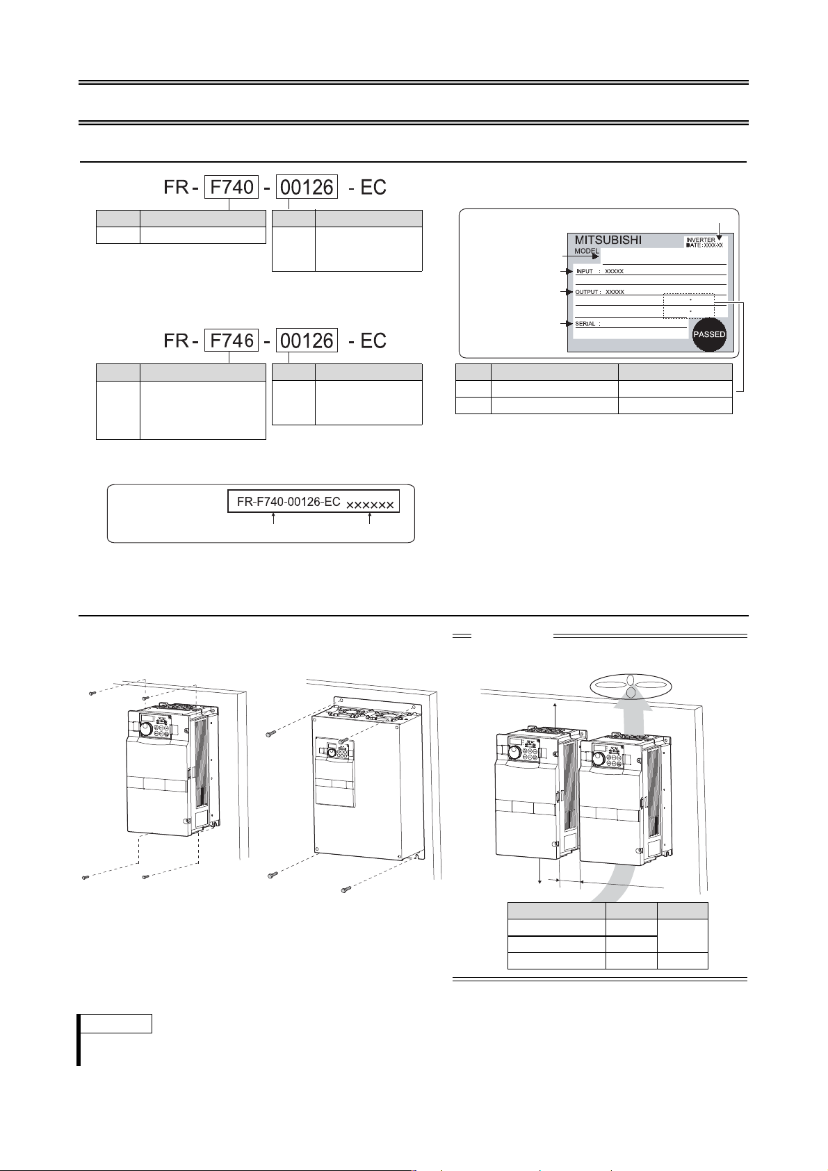
1.1 Inverter Type
Symbol Voltage Class
F740 Three-phase 400V class
Symbol Type number
00023
to
12120
Displays the
rated current
Capacity plate example
Rating plate example
Inverter type Serial number
Inverter type
Input rating
Output rating
Serial number
Overload current rating Ambient temperature
LD 120% 60s, 150% 3s 50°C
SLD 110% 60s, 120% 3s 40°C
Symbol Voltage Class
F746
Three-phase 400V class/
waterproof structure IP54
(standard IEC 60529:
2001) specification
Symbol Type number
00023
to
01160
Displays the
rated current
Production year-month
00023 to 00620
00770 to 12120
Fix six positions for the FR-F740-04320 to 08660 and
fix eight positions for the FR-F740-09620 to 12120.
CAUTION
앫
When encasing multiple inverters, install them in parallel
and leave clearance as a cooling measure.
Y
Y
X
Inverter Capacity X [cm] Y [cm]
≤ 00083 ≥ 1
≥ 10
00126–01160 ≥ 5
≥ 01800 ≥ 10 ≥ 20
FR-F740-00126-EC
LD (50 C) XXA
SLD (40 C) XXA
1.2 Installation of the inverter
Installation on the panel
Notes
앫 It is not necessary to leave spaces on both sides of the inverter FR-F746.
앫 Some inverter models may be installed outside an enclosure. See Appendix A.2 for details.
1

INSTALLATION AND INSTRUCTIONS
Inverter
x = Measurement position
1.3 General Precaution
The bus capacitor discharge time is 10 minutes. Before starting wiring or inspection, switch power off, wait for more than
10 minutes, and check for residual voltage between terminal P/+ and N/
−
with a meter etc., to avoid a hazard of electrical
shock.
1.4 Environment
Before installation, check that the environment meets following specifications:
Enclosure
−10°C to +50°C (+40°C for FR-F746)
(non-freezing) for selected overload capability 150% (Pr. 570 = 0)
Ambient temperature
햳
−10°C to +40°C (+30°C for FR-F746)
(non-freezing) for selected overload capability 120% (Pr. 570 = 1)
5 cm5 cm
5 cm
Ambient humidity
Storage temperature
Atmosphere
Altitude
Vibration
햲
2.9m/s² or less for the 04320 or more.
햳
Temperature measured at a measurement position in an enclosure.
90% RH or less (non-condensing)
−20°C to +65°C
Indoors (No corrosive and flammable gases, oil mist, dust and dirt)
Maximum 1000 m above sea level
2 햲
5.9m/s
or less at 10 to 55 Hz (directions of X, Y, Z axes)
CAUTION
앫 Install the inverter on a strong surface securely and vertically with bolts.
앫 Leave enough clearances and take cooling measures.
앫 Avoid places where the inverter is subjected to direct sunlight, high temperature and high humidity.
앫 Install the inverter on a non-combustible surface.
2
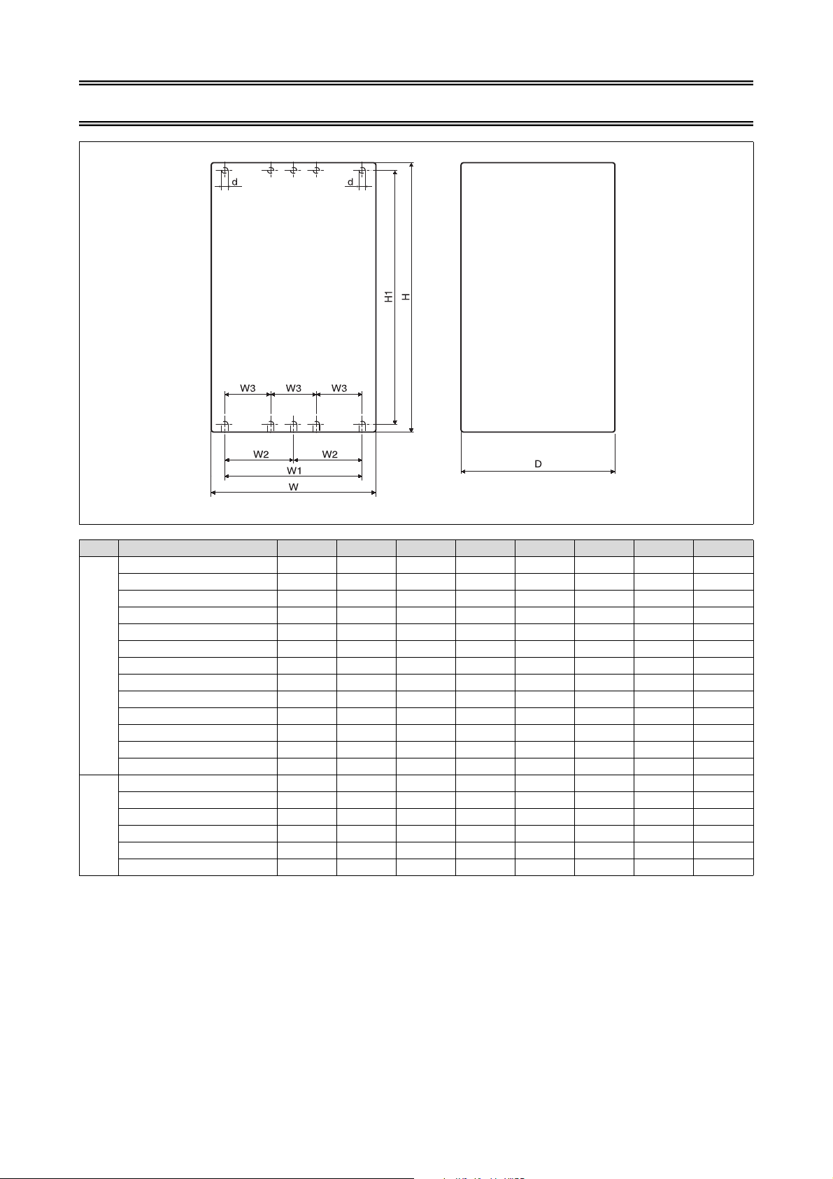
2 OUTLINE DRAWING
Inverter Type W W1 W2 W3 H H1 D d
FR-F740-00023–00126-EC 150 125 — — 260 245 140 6
FR-F740-00170/00250-EC 220 195 — — 260 245 170 6
FR-F740-00310/00380-EC 220 195 — — 300 285 190 6
FR-F740-00470/00620-EC 250 230 — — 400 380 190 10
FR-F740-00770-EC 325 270 — — 550 530 195 10
FR-F740-00930/01160-EC 435 380 — — 550 525 250 12
FR-F740-01800-EC 465 380 — — 550 525 250 12
FR-F740-02160/02600-EC 465 400 — — 620 595 300 12
FR-F740
FR-F740-03250/03610-EC 465 400 — — 740 715 360 12
FR-F740-04320/04810-EC 498 400 200 — 1010 985 380 12
FR-F740-05470–06830-EC 680 600 300 — 1010 985 380 12
FR-F740-07700/08660-EC 790 630 315 — 1330 1300 440 12
FR-F740-09620–12120-EC 995 900 — 300 1580 1550 440 12
FR-F746-00023–00126-EC 249 180 — — 395 380 210 7
FR-F746-00170/00250-EC 319 255 — — 395 380 240 7
FR-F746-00310/00380-EC 319 258 — — 445 425 260 10
FR-F746-00470/00620-EC 354 312 — — 560 540 260 10
FR-F746
FR-F746-00770-EC 360 300 — — 590 570 265 10
FR-F746-00930/01160-EC 471 411 — — 660 635 320 12
(Unit: mm)
3
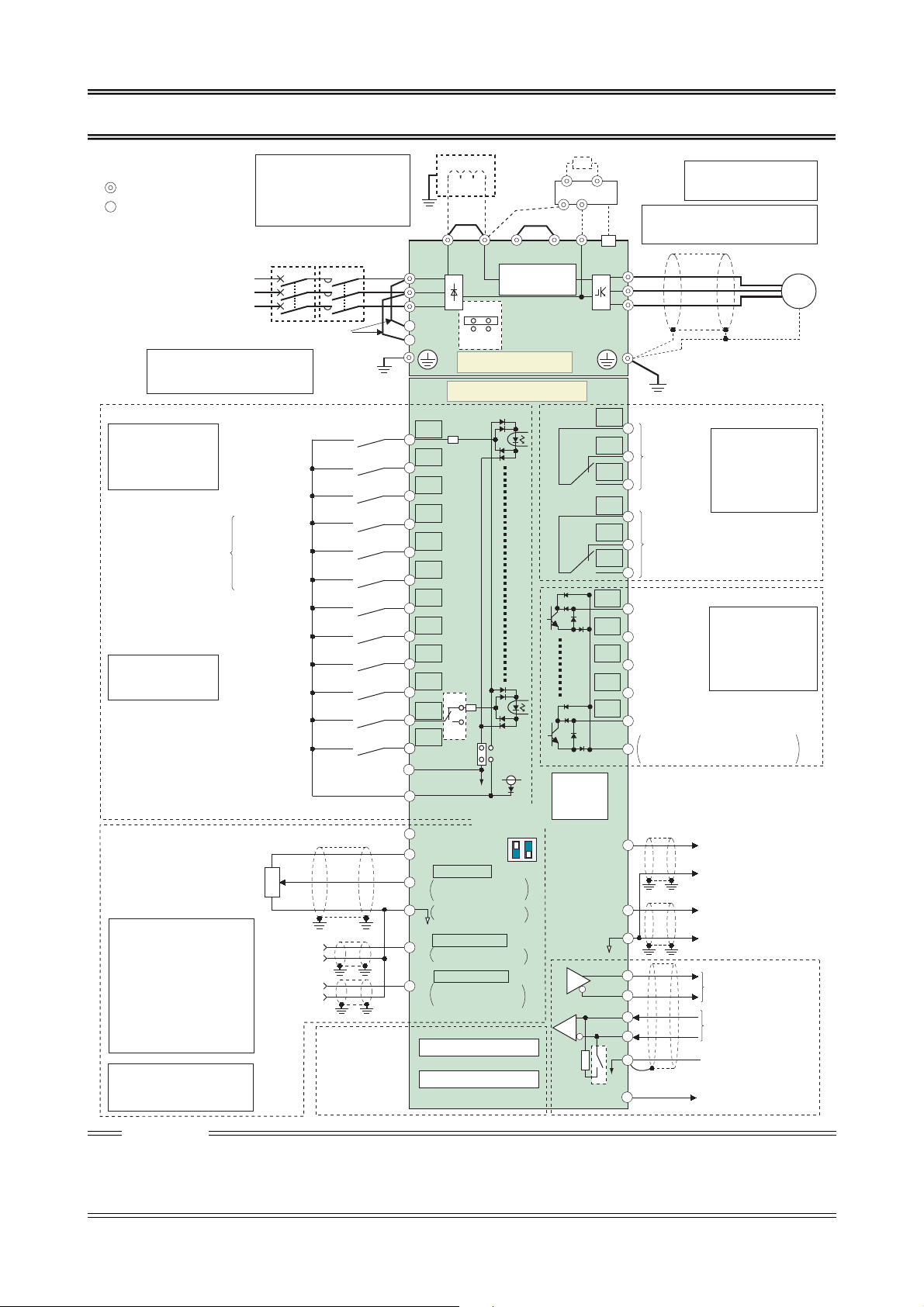
3 WIRING
Source logic
Main circuit terminal
Control circuit terminal
Jumper Jumper
Jumper
*1.DC reactor
Remove the jumper across P1
and P/+ for the 01160 or less if a
DC reactor is connected. Be sure
to connect the DC reactor sup-
plied with the 01800 or more.
Earth
*6.The CN8 connector (for
MT-BU) is provided with the
01800 or more
Earth
Motor
*2.To supply power to the control circuit
separately, remove the jumper
across R1/L11 and S1/L21.
3-phase AC
power supply
Connector for
with/without internal
EMC filter
Main circuit
Control circuit
Terminal functions
vary with the input
terminal assignment.
(Pr. 178 to Pr. 189)
Control input signals (No voltage input allowed)
Forward rotation
start
Reverse rotation
start
Start self-holding selection
High speed
Middle speed
Low speed
Multi-speed selection
Jog operation
Second function selection
Output stop
Reset
Terminal 4 input selection
(Current input selection)
Selection of automatic restart after
instantaneous power failure
Contact input common (Sink*)
*3. AU terminal can be
used as PTC input
terminal.
24VDC power supply/max. 100mA load current
Contact input common(Source*)
*(Common for external power supply transistor)
Frequency setting signal (Analog)
Auxiliary
input
Terminal 4
input
(Current
input)
0 to 5VDC
0 to ±10VDC
4 to 20mADC
0 to 10VDC
4 to 20mADC
0 to ±5VDC
0 to 5VDC
0 to 10VDC
PU
connector
Connector for
plug-in option
connection
Option connector 1
Terminating
resistor
*4.Terminal input specifications
can be changed by analog
input specifications switchover
(Pr. 73, Pr. 267) (initial settings
in frame). Set the voltage/current input switch in the OFF
position to select voltage input
(0 to 5V/0 to 10V) and ON to
select current input (0 to
20mA). Terminal 2 and 10 can
be used as PTC input terminal.
(Pr. 561).
*5.It is recommended to use 2W,
1k
Ω
when the frequency setting signal is changed frequently.
Relay output 1
(Alarm output)
Relay output 2
Running
Instantaneous
power failure
Up to frequency
Overload
Terminal functions
vary with the output
terminal assignment.
(Pr. 195, Pr. 196)
Terminal functions
vary with the output
terminal assignment.
(Pr. 190 to Pr. 194)
Frequency detection
Open collector output common
Sink/source common
Analog current output
(0 to 20mADC)
Analog signal output
(0 to 10VDC)
RS-485 terminals
Data transmission
Data reception
(Permissible load
current 100mA)
Frequency setting
potentiometer
1/2W, 1k
Ω
M
3~
Earth
Inrush current
limit circuit
*7 Do not use PR and PX terminals.
Please do not remove the jumper connected to terminal PR and PX.
Brake resistor
(Option)
Brake unit
(Option)
Open collector output
Relay output
Voltage/current
input switch
Option connector 2
Analog common
CAUTION
*5
앫 To prevent a malfunction due to noise, keep the signal cables more than 10cm away from the power cables.
앫 After wiring, wire offcuts must not be left in the inverter.
Wire offcuts can cause an alarm, failure or malfunction. Always keep the inverter clean.
When drilling mounting holes in a control box etc., take care not to allow chips and other foreign matter to enter the inverter.
앫 Set the voltage/current input switch in the correct position. An incorrect setting may cause a fault, failure or malfunction.
4
MCCB
3
2
1
(+)
(-)
(+)
(-)
MC
*2
P1
R/L1
S/L2
T/L3
R1/L11
S1/L21
STF
STR
STOP
RH
RM
RL
JOG
RT
MRS
RES
*3
AU
AU
PTC
CS
SD
PC
10E(+10V)
10(+5V)
2
5
1
4
*1
P/+
ON
OFF
SOURCE
*4
OFF
PR*7
SINK
24V
4
ON
PX*7
N/-
CN8*6
U
V
W
C1
B1
A1
C2
B2
A2
RUN
SU
IPF
OL
FU
2
*
4
*
4
SE
CA
AM
5
TXD+
*
4
TXD-
RXD+
RXD-
SG
VCC
(+)
(-)
(+)
(-)
GND
5V
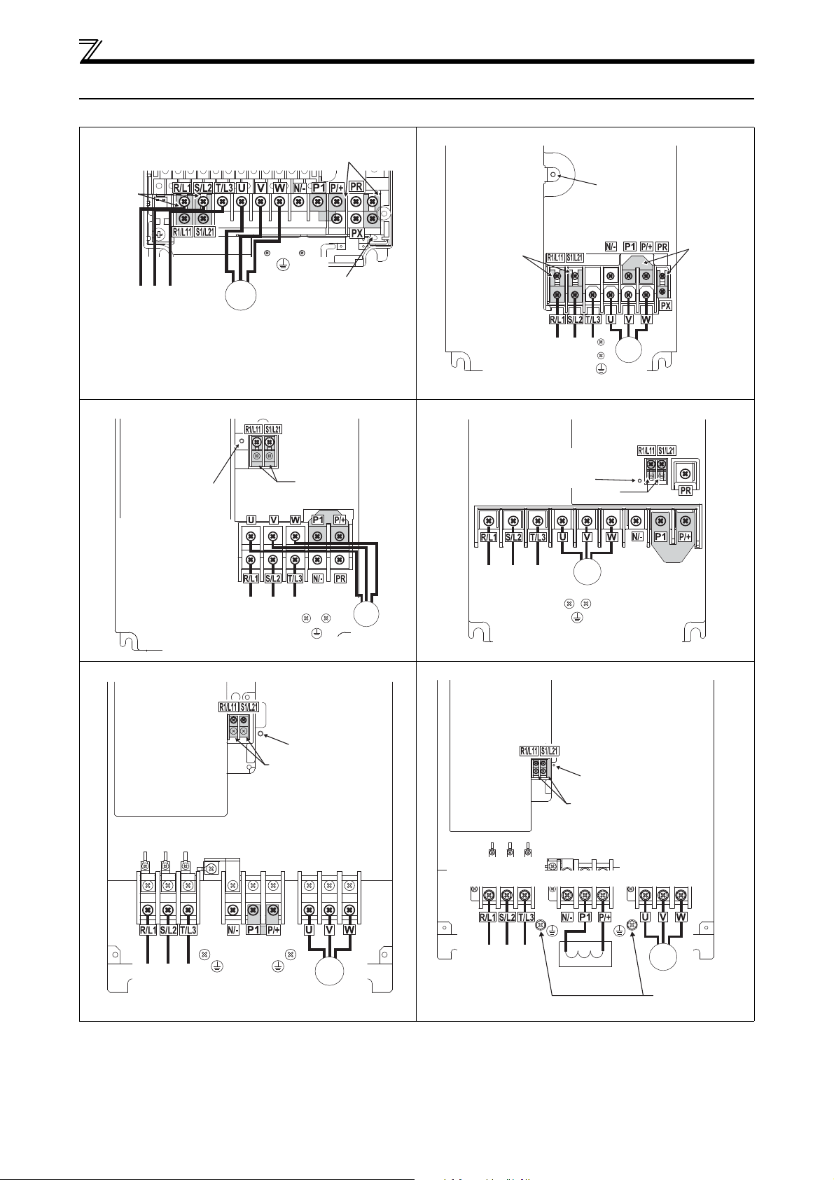
3.1 Main circuit terminal
Screw size (M4)
Jumper
Charge lamp
Screw size
(M4)
Motor
Power supply
M
3 ~
L1 L2 L3
Jumper
Jumper
Jumper
Charge lamp
Power supply
Screw size (M4)
Motor
Screw size
(M4)
M
3 ~
L1 L2 L3
Jumper
Charge lamp
Screw size (M5)
Screw size (M5)
Power supply
Motor
Jumper
Screw size
(M4)
M
3 ~
L1 L2 L3
Jumper
Jumper
Charge lamp
Screw size (M4)
Screw size (M6)
Power supply Motor
Screw size (M6)
M
3 ~
L1 L2 L3
Screw size (M4)
Charge lamp
Jumper
Screw size
(00770: M6)
00930A, 01160A: M8)
Jumper
Power
supply
Screw size
(00770: M6
00930, 01160: M8)
Motor
M
3 ~
L1 L2 L3
Screw size
(M4)
Screw size
(01800: M8, 02160: M10)
Screw size (M10)
Power
supply
Motor
DC reactor
Screw size
(01800: M8,
02160, 02600: M10)
Jumper
Charge lamp
M
3 ~
L1 L2 L3
Screw size
(01800: M8,
02160, 02600: M10)
3.1.1 Terminal layout and wiring
FR-F740/746-00023, 00038, 00052, 00083, 00126-EC FR-F740/746-00170, 00250-EC
FR-F740/746-00310, 00380-EC FR-F740/746-00470, 00620-EC
WIRING
FR-F740/746-00700 to 01160-EC FR-F740-01800 to 02600-EC
5
 Loading...