

Mitsubishi FR-F720-00046-NA, FR-F720-00167-NA, FR-F720-00077-NA, FR-F720-00105-NA, FR-F720-00250-NA Instruction Manual
...
INSTRUCTION MANUAL (BASIC)
FR-F720-00046 to 02330-NA
FR-F740-00023 to 03610-NA
INVERTER
INVERTER FR-F700-NA INSTRUCTION MANUAL (BASIC)
1
2
3
4
5
6
CONTENTS
PRODUCT CHECKING AND PARTS IDENTIFICATION..............................1
INSTALLATION AND WIRING......................................................................2
2.1 Peripheral devices .....................................................................................................3
2.2 Method of removal and reinstallation of the front cover............................................4
2.3 Installation of the inverter and instructions................................................................6
2.4 Wiring.........................................................................................................................8
2.5 Power-off and magnetic contactor (MC)..................................................................25
2.6 Precautions for use of the inverter...........................................................................26
DRIVE THE MOTO R ....... ... .. .......................... ..............................................27
3.1 Step of operation .....................................................................................................27
3.2 Operation panel (FR-DU07) ....................................................................................28
3.3 Overheat protection of the motor by the inverter (Pr.9)...........................................32
3.4 When the rated motor frequency is 50Hz (Pr.3)......................................................33
3.5 Operation by the start command from the operation panel (PU operation mode)..34
3.6 Operation by the start command of the terminal block (external operation)...........42
ADJUSTMENT .............................................................................................50
4.1 Simple mode parameter list.....................................................................................50
4.2 Increase the starting torque (Pr. 0)..........................................................................52
4.3 Limit the maximum and minimum output frequency (Pr.1, Pr.2).............................53
4.4 Change acceleration and deceleration time (Pr.7, Pr.8).........................................54
4.5 Energy saving operation (Pr. 60).............................................................................55
4.6 Selection of the operation command and frequency command locations (Pr.79)..57
4.7 Parameter clear .......................................................................................................58
4.8 All parameter clear...................................................................................................59
4.9 Parameter copy .......................................................................................................60
4.10 Parameter verification..............................................................................................61
TROUBLESHOOTING.................................................................................62
5.1 List of alarm display.................................................................................................62
5.2 Causes and corrective actions ................................................................................63
5.3 Reset method of protective function........................................................................74
5.4 Correspondences between digital and actual characters.......................................74
5.5 Check and clear of the alarm history.......................................................................75
5.6 Check first when you have troubles........................................................................77
PRECAUTIONS FOR MAINTENANCE AND INSPECTION .......................79
Thank you for choosing this Mitsubishi Inverter.
This Instruction Manual (basic) is intended for users who "just want to run the inverter".
If you are going to utilize functions and performance, refer to the Instruction Manual (applied) [IB-0600217ENG].
Please read the provided CD-ROM for the instruction manual (applied).
1
2
3
4
5
6
This instruction manual (basic) provides handling information and precautions for use of the equipment.
WARNING
CAUTION
CAUTION
WARNING
CAUTION
CAUTION
CAUTION
Environment
Ambient
temperature
LD -10°C to +50°C (14°F to 122°F)(non-freezing)
SLD
(initial setting)
-10°C to +40°C (14°F to 104°F)(non-freezing)
Ambient humidity 90% RH or less (non-condensing)
Storage temperature -20°C to +65°C * (-4°F to 149°F)
Atmosphere
Indoors (free from corrosive gas, flammab le
gas, oil mist, dust and dirt)
Altitude, vibration
Maximum 1000m (3280.80feet) above sea
level for standard oper ation. After that der at e
by 3% for every extra 500m ( 1640.40feet) up
to 2500m (8202feet) (92 %) 5. 9m/s
2
or less
(conforming to JIS C 60068- 2- 6 )
CAUTION
CAUTION
WARNING
CAUTION
CAUTION
CAUTION
CAUTION
Please forward this instruction manual (basic) to the end user.
This section is specifically about safety matters
Do not attempt to install , op era te, ma intai n or insp ect t he i n ver ter unt il you
have read through this instruction manual (basic) and appended
documents carefully and can use th e equip ment correctl y. Do not use the
inverter until you have a full knowledge of the equipment, safety
information and instruction s. In this instruction manual (basic ), the safety
instruction levels are classified into "WARNING" and "CAUTION".
Note that even the level may lead to a serious consequence
according to conditions. Please follow the instructions of both levels
because they are important to personnel safety.
1. Electric Shock Preven tion
• While power is on or when the inverter is running, do not open the front cover.
Otherwise you may get an electric shock.m
• Do not run the inverter with the front cover or wiring cover removed.
Otherwise, you may access the exposed high-voltage terminals or the
charging part of the circuitry and get an electric shock.
•
Even if power is o ff, do not remove the front c over except for wiring or periodic
inspection.You may access the charged inverter circuits and get an electric shock.
• Before starting wiring or inspection, check to make sure that the operation
panel indicator is off, wait for at least 10 minutes after the power supply has
been switched off, and check that there are no residual voltage using a tester
or the like. The capacitor is charged with high voltage for some time after
power off and it is dangerous.
• This inverter must be
of national and local safety regulations and electrical codes. (JIS, NEC
section 250, IEC 536 class 1 and other applicable standards)
• Any person who is involved in the wiring or inspection of this equipment
should be fully competent to do the work.
• Always install t he inverter before wi ring. Otherwise, yo u may get an electric
shock or be injured.
• Perform setting dial and key operations with dry hands to prevent an electric
shock. Otherwise you may get an electric shock.
• Do not subject the cables to scratches, excessive stress, heavy loads or
pinching. Otherwise you may get an electric shock.
• Do not replace the cooling fan while power is on. It is dangerous to replace
the cooling fan while power is on.
•
Do not touch the printed circuit board with wet hands. You may get an electric shock.
2. Fire Prevention
• Mount the inverter to incombustible material. Mounting it to or near
combustible material can cause a fire.
• If the inverter has become faulty, switch off the inverter power.
A continuous flow of large current could cause a fire.
•
Do not connect a resistor directly to the DC terminals P/+, N/−. This could cause a fire.
3. Injury Prevention
• Apply only the voltage specified in the instruction manual to each terminal.
Otherwise, burst, damage, etc. may occur.
• Ensure that the cables are connected to the correct terminals. Otherwise,
burst, damage, etc. may occur.
• Always make sure that polarity is correct to prevent damage, etc. Otherwise,
burst, damage, etc. may occur.
• While power is on or for some time after power-off, do not touch the inverter
as it is hot and you may get burnt.
4. Additional Instructions
Also note the following points to prevent an accidental failure, injury, electric
shock, etc.
(1) Transportation and instal lation
Assumes that incorrect handling may cause hazardous
conditions, resulting in death or severe inju ry.
Assumes that incorrect handling may cause
hazardous conditions, resulting in medium or
slight injury, or may cause physical damage only.
grounded. Grounding must conform to the requirements
(2) Wiring
• Do not install a power factor correction capacitor or surge suppressor on the
inverter output side.
• The connection orientation of the output cables U, V, W to the motor will affect
the direction of rotation of the motor.
(3) Test operation and adjustment
• Before starting operation, confirm and adjust the parameters. A failure to do
so may cause some machines to make unexpected motions.
(4) Operation
• When you have chosen the retry function, stay away from the equipment as it
will restart suddenly after an alarm stop.
• The key is valid only when the appropriate function setting has been
made. Prepare an emergency stop switch separately.
• Make sure that the start signal is off before resetting the inverter alarm. A
failure to do so may restart the motor suddenly.
• The load used should be a three-phase induction motor only. Connection of any
other electrical equipment to the inverter output may damage the equipment.
• Do not modify the equipment.
• Do not perform parts removal which is not instructed in this manual. Doing so
may lead to fault or damage of the inverter.
• The electronic thermal relay function does not guarantee protection of the
motor from overheating.
• Do not use a magnetic contactor on the inverter input for frequent starting/
stopping of the inverter.
• Use a noise filter to reduce the effect of electromagnetic interference.
Otherwise nearby electronic equipment may be affected.
• Take measures to suppress harmonics. Otherwise power supply harmonics
from the inverter may heat/damage the power factor correction capacitor and
generator.
• When a 400V class motor is inverter-driven, please use an insulationenhanced motor or measures taken to suppress surge voltages. Surge
voltages attributable to the wiring constants may occur at the motor terminals,
deteriorating the insulation of the motor.
• When parameter clear or all clear is performed, reset the required
parameters before starting operations. Each parameter returns to the initial
value.
• The inverter can be easily set for high-speed operation. Before changing its
setting, fully examine the performances of the motor and machine.
• In addition to the inverter's holding function, install a holding device to ensure
safety.
• Before running an inverter which had been stored for a long period, always
perform inspection and test operation.
• For prevention of damage due to static electricity, touch nearby metal before
touching this product to eliminate static electricity from your body.
(5) Emergency stop
• Provide a safety backup such as an emergency bra ke which will prevent the
machine and equipment from hazardous conditions if the inverter fails.
• When the breaker on the inverter input side trips, check for the wiring fault
(short circuit), damage to internal parts of the inverter, etc. Identify the cause
of the trip, then remove the cause and power on the breaker.
• When the protective function is activated, take the corresponding corrective
action, then reset the inverter, and resume operation.
(6) Maintenance, inspection and parts replacement
• Do not carry out a megger (insulation resistance) test on the control circuit of
the inverter.
(7) Disposing of the inverter
• When carrying products, use correct lifting gear to prevent injury.
• Do not stack the inverter boxes higher than the number recommended.
• Ensure that installation position and material can withstand the weight of the
inverter. Install according to the information in the instruction manual.
• Do not install or operate the inverter if it is damaged or has parts missing.
• When carrying the inverter, do not hold it by the front cover or setting dial; it
may fall off or fail.
• Do not stand or rest heavy objects on the product.
• Check the inverter mounting orientation is correct.
• Prevent other conductive bodies such as screws and metal fragments or
other flammable substance such as oil from entering the inverter.
• As the inverter is a precision instrument, do not drop or subject it to impact.
• Use the inverter under the following environmental conditions. Otherwise, the
inverter may be damaged.
*Temperature applicable for a short time, e.g. in transit.
• Treat as industrial waste.
General instructions
Many of the diagrams and dra wings in this inst ruction manual (ba sic) show
the inverter without a cover, or partially open. Never ru n the inverter in this
status. Always replace the cover and follow this instr uction manual (basic)
when operating the inverter.
A-1

— CONTENTS —
1 PRODUCT CHECKING AND PARTS IDENTIFICATION 1
2 INSTALLATION AND WIRING 2
2.1 Peripheral devices .................................................................................................3
2.2 Method of removal and reinstallation of the front cover.........................................4
2.3 Installation of the inverter and instructions.............................................................6
2.4 Wiring.....................................................................................................................8
2.4.1 Terminal connection diagram ..... ...... ....... ...... ....... ...... ...... ......................................................... 8
2.4.2 Specification of main circuit terminal......................................................................................... 9
2.4.3 Terminal arrangement of the main circuit terminal, power supply and the motor wiring. ..........9
2.4.4 Control circuit terminals........................................................................................................... 16
2.4.5 When connecting the operation panel using a connection cable ............................................ 23
2.4.6 Connector with/without EMC filter ...........................................................................................23
2.4.7 RS-485 terminal block .............................................................................................................24
2.4.8 Communication operation........................................................................................................ 24
2.5 Power-off and magnetic contactor (MC)..............................................................25
2.6 Precautions for use of the inverter.......................................................................26
3 DRIVE THE MOTOR 27
3.1 Step of operation..................................................................................................27
3.2 Operation panel (FR-DU07)................................. ..... .... ................................. ......28
3.2.1 Parts of the operation panel (FR-DU07)..................................................................................28
3.2.2 Basic operation (factory setting) .............................................................................................. 29
3.2.3 Operation lock (Press [MODE] for an extended time (2s))...................................................... 30
3.2.4 Monitoring of output current and output voltage...................................................................... 31
3.2.5 First priority monitor.................................................... ...... ....... ................................................ 31
3.2.6 Setting dial push...................................................................................................................... 31
3.3 Overheat protection of the motor by the inverter (Pr.9) .......................................32
3.4 When the rated motor frequency is 50Hz (Pr.3) ..................................................33
3.5 Operation by the start command from the operation panel (PU operation mode)34
3.5.1 Set the set frequency to operate (example: performing operation at 30Hz)............................34
3.5.2 Use the setting dial like a potentiometer to perform operation. ............................................... 35
3.5.3 Use switches to give a start command and a frequency command (multi-speed setting)....... 36
3.5.4 Perform frequency setting by analog (voltage input)............................................................... 38
3.5.5 Perform frequency setting by analog (current input) ............................................................... 40
3.6 Operation by the start command of the terminal block (external operation)........42
3.6.1 Use the set frequency set by the operation panel (Pr. 79=3) .................................................. 42
3.6.2 Use switches to give a start command and a frequency command
(multi-speed setting) (Pr. 4 to Pr.6) .........................................................................................44
3.6.3 Perform frequency setting by analog (voltage input)............................................................... 46
3.6.4 Change the frequency (60Hz) of the maximum value of potentiometer (at 5V) ......................47
3.6.5 Perform frequency setting by analog (current input) ............................................................... 48
3.6.6 Change the frequency (60Hz) of the maximum value of potentiometer (at 20mA) .................49
I

4 ADJUSTMENT 50
4.1 Simple mode parameter list .................................................................................50
4.2 Increase the starting torque (Pr. 0)......................................................................52
4.3 Limit the maximum and minimum output frequency (Pr.1, Pr.2)..........................53
4.4 Change acceleration and deceleration time (Pr.7, Pr.8)......................................54
4.5 Energy saving operation (Pr. 60).........................................................................55
4.5.1 Energy saving operation mode (setting "4")............................................................................ 55
4.5.2 Optimum excitation control mode (setting "9")......................................................................... 55
4.6 Selection of t he operation command and frequency command locations (Pr.79)57
4.7 Parameter clear ...................................................................................................58
4.8 All parameter clear...............................................................................................59
4.9 Parameter copy....................................................................................................60
4.10 Parameter verification..........................................................................................61
5 TROUBLESHOOTING 62
5.1 List of alarm display.............................................................................................62
5.2 Causes and corrective actions.............................................................................63
5.3 Reset method of protective function ....................................................................74
5.4 Correspondences between digital and actual characters....................................74
5.5 Check and clear of the alarm history ...................................................................75
5.6 Check first when you have troubles.....................................................................77
5.6.1 Motor does not rotate as commanded.....................................................................................77
5.6.2 Motor generates abnormal noise.............................................................................................77
5.6.3 Motor generates heat abnormally............................................................................................77
5.6.4 Motor rotates in opposite direction.......................................................................................... 78
5.6.5 Speed greatly differs from the setting......................................................................................78
5.6.6 Acceleration/deceleration is not smooth..................................................................................78
5.6.7 Motor current is large............................................................................................................... 78
5.6.8 Speed does not increase......................................................................................................... 78
5.6.9 Speed varies during operation................................................................................................. 78
5.6.10 Operation panel (FR-DU07) display is not operating............................................................... 78
5.6.11 Parameter write cannot be performed..................................................................................... 78
CONTENTS
6 PRECAUTIONS FOR MAINTENANCE AND INSPECTION 79
6.1 Inspection Item .....................................................................................................79
6.1.1 Daily inspection .......................................................................................................................79
6.1.2 Periodic inspection ........................... ....... ...... .......................................................................... 79
6.1.3 Daily and periodic inspection...................................................................................................80
6.1.4 Display of the life of the inverter parts..................................................................................... 81
6.1.5 Checking the inverter and converter modules......................................................................... 83
II

6.1.6 Cleaning ..................................................................................................................................83
6.1.7 Replacement of parts ..............................................................................................................84
6.1.8 Inverter replacement................................................................................................................ 87
6.2 Measurement of main circuit voltages, currents and powers...............................88
6.2.1 Insulation resistance test using megger..................................................................................88
6.2.2 Pressure test ........................................................................................................................... 88
6.2.3 Measurement of voltages and currents................................................................................... 88
7 SPECIFICATIONS 90
7.1 Rating...................................................................................................................90
7.2 Common specifications........................................................................................92
7.3 Outline dimension drawings.................................................................................94
7.3.1 Inverter outline dimension drawings........................................................................................94
7.3.2 Operation panel (FR-DU07) outline dimension drawings........................................................ 99
7.3.3 Parameter unit (FR-PU04) outline dimension drawings.......................................................... 99
APPENDICES 100
Appendix 1 List of parameters classified by purpose of use....................................... 100
Appendix 2 Extended parameters............................................................................... 102
Appendix 3For customers who have replaced the older model with this inverter....... 125
Appendix 3-1Replacement of the FR-F500 series ............................................................................. 125
Appendix 3-2Replacement of the FR-A100 <EXCELENT> series .................................................... 126
Appendix 4 Instructions for UL and cUL...................................................................... 127
Appendix 5 Instructions for Compliance with the European Directives....................... 128
<Abbreviations>
DU: Operation panel (FR-DU07)
PU: Operation panel(FR-DU07) and parameter unit (FR-PU04)
Inverter: Mitsubishi inverter FR-F700 series
FR-F700: Mitsubishi inverter FR-F700 series
Pr.: Parameter Number
PU operation: Operation using the PU (FR-DU07/FR-PU04).
External operation: Operation using the control circuit signals
Combined operation: Combined operation using the PU (FR-DU07/FR-PU04) and external operation
Standard motor: SF-JR
Constant-torque motor: SF-HRCA
<Trademarks>
ONWORKS is registered trademarks of Echelon Corporation in the U.S.A. and other countries.
L
Company and product names herein are the trademarks and registered trademarks of their respective owners.
III
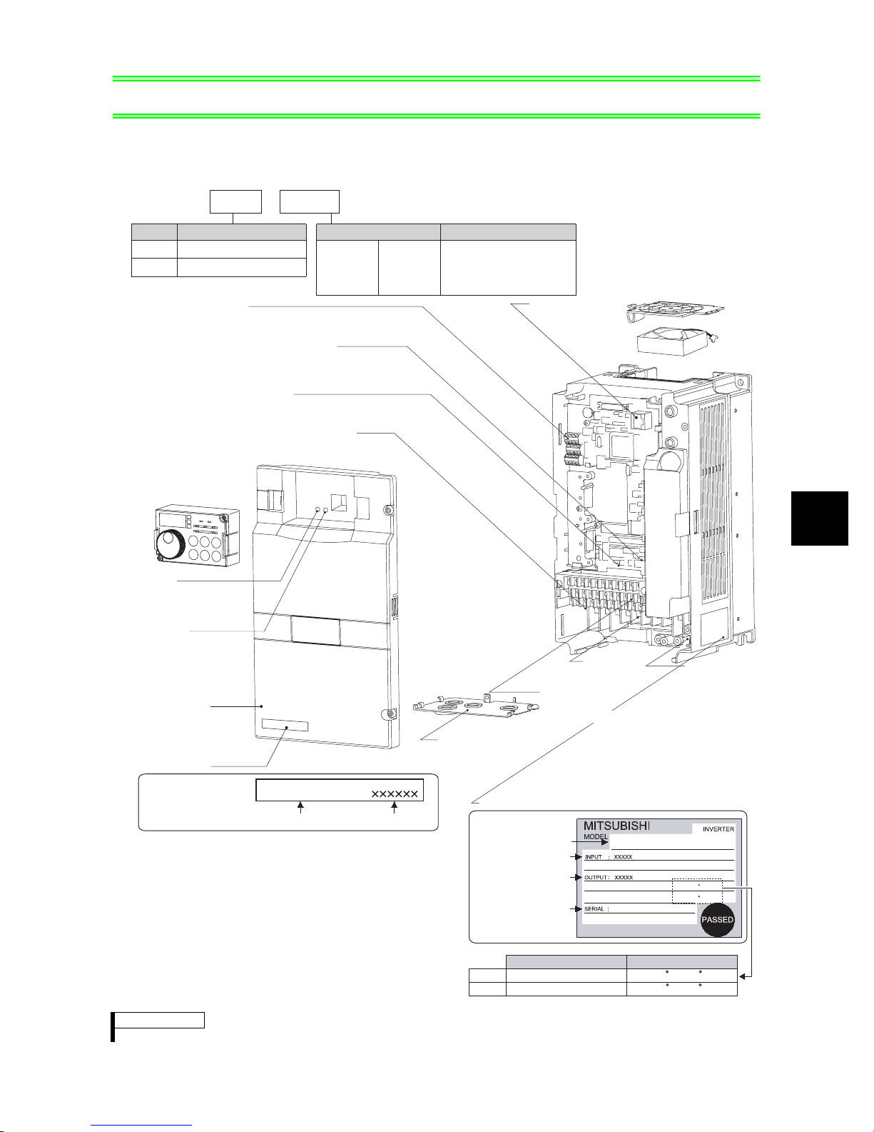
1
PRODUCT CHECKING AND PARTS IDENTIFICATION
Wiring cover
Rating plate
Inverter type
Operation panel (FR-DU07)
Front cover
Connector with/without EMC filter
Control circuit
terminal block
AU/PTC switchover switch
Main circuit
terminal block
Charge lamp
Lit when power
is supplied to
the main circuit
Power lamp
Lit when the control circuit
(R1/L11, S1/L21) is supplied
with power.
Cooling fan
• Inverter Type
PU connector
RS-485 terminal
Connector for plug-in option connection
(Refer to the instruction manual of options.)
ALARM lamp
Lit when the inverter is
in the alarm status
(major fault).
Capacity plate
Inverter type
Serial number
Capacity plate
Input rating
Output rating
Serial number
Rating plate
00126
FR-F740-00126-NA
FR-F740-00126-NA
- NA
FR --F740
Symbol
F720
Voltage Class
Three-phase 200V class
F740 Three-phase 400V class
Symbol
200V class
00046
to
02330
Displays the rated current
Rated Inverter Current
LD (50 C) XXA
SLD (40 C) XXA
Overload Current Rating Ambient Temperature
LD 120% 60s, 150% 3s 50 C (122 F)
SLD 110% 60s, 120% 3s 40 C (104 F)
400V class
00023
to
03610
(Refer to page 23)
(Refer to page 24)
(Refer to page 4)
(Refer to page 23)
(Refer to page 9)
(Refer to page 84)
(Refer to page 23)
(Refer to the Instruction Manual (ap p li ed).)
(Refer to page 16)
(Refer to page 6)
(Refer to page 4)
(Refer to page 9)
1
PRODUCT CHECKING AND P ARTS IDENTIFICATION
Unpack the inverter and check the capacity plate on the front cover and the rating plate on the inverter side face to
ensure that the product agrees with your order and the inverter is intact.
REMARKS
For removal and reinstallation of covers, refer to page 4.
1
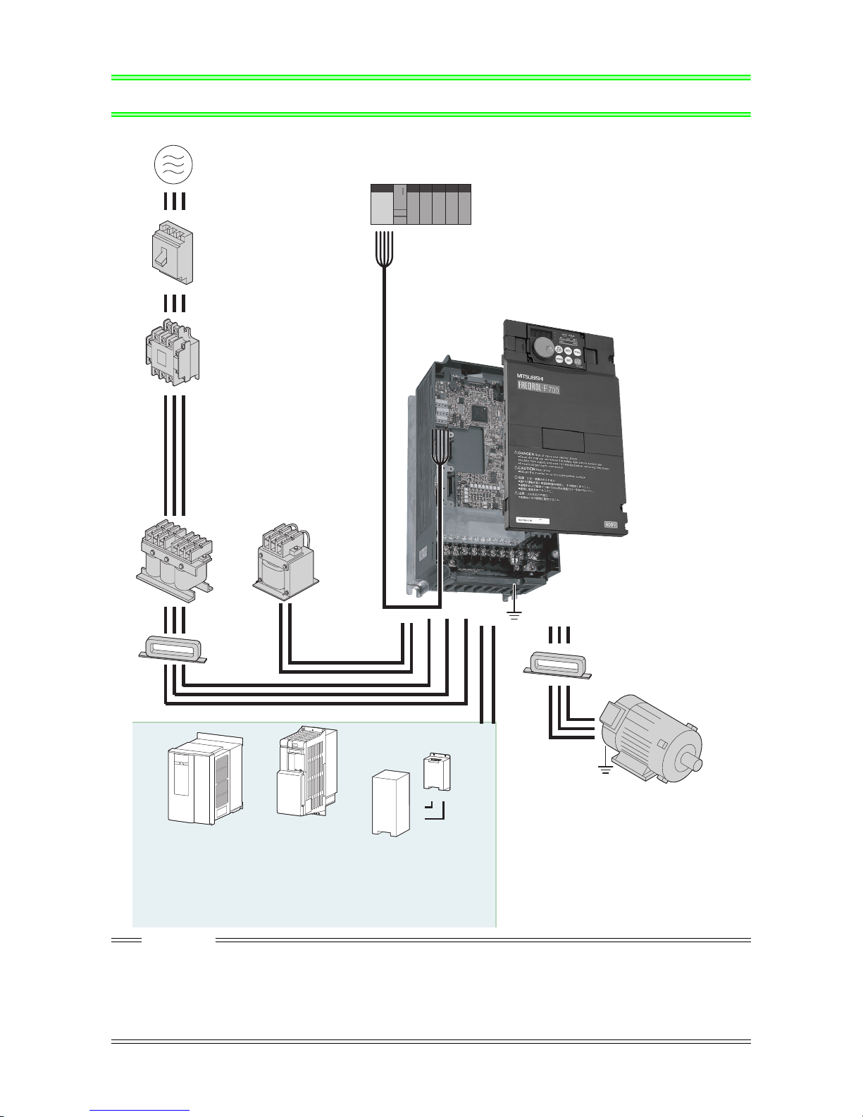
2 INSTALLATION AND WIRING
Three-phase AC power supply
Use within the permissible power supply
specifications of the inverter.
(Refer to page 90)
Moulded case circuit
breaker (MCCB)
or earth leakage circuit
breaker (ELB), fuse
The breaker must be selected carefully since
an in-rush current flows in the inverter at
power on.
(Refer to page 3)
Magnetic contactor(MC)
Install the magnetic contactor to ensure safety.
Do not use this magnetic contactor to start and
stop the inverter.
Doing so will cause the inverter life to be shorten.
(Refer to page 3)
Reactor (FR-HAL, FR-HEL)
Reactors (option) should be used when power
harmonics measures are taken, the power factor
is to be improved or the inverter is installed near a
large power supply system (1000kVA or more).
The inverter may be damaged if you do not use
reactors.
Select the reactor according to the model.
Remove the jumpers across terminals P/+-P1 to
connect to the DC reactor.
(Refer to the Instruction Manual (applied).)
PLC
RS-485 terminal block
The inverter can be
connected with computers
such as PLC.
It supports Mitsubishi inverter
protocol and Modbus-RTU
(binary) protocol.
Inverter
(FR-F700)
The life of the inverter is influenced by ambient
temperature. The ambient temperature should be as low
as possible within the permissible range. Especially when
mounting the inverter inside an enclosure, take cautions
of the ambient temperature. (Refer to page 6)
Wrong wiring might lead to damage o f the inverter. The
control signal lines must be kept fully away from the main
circuit to protect them from noise.(Refer to page 8)
Refer to page 23 for the built-in EMC filter.
Noise filter
AC reactor
(FR-HAL)
Noise filter
(FR-BLF)
It is not necessary
for the 200V class and
the FR-F740-01160 or less.
DC reactor
(FR-HEL)
For the FR-F740-01800
or more, a DC reactor is
supplied.
P/+
P1
R/L1 S/L2 T/L3
N/-P/+
Ground
UVW
(FR-BSF01, FR-BLF)
Install a noise filter to reduce
the electromagnetic noise
generated from the inverter.
Effective in the range from
about 1MHz to 10MHz.
When more wires are passed
through, a more effective result
can be obtained.
Motor
Brake unit
*1
, MT-BU5*2)
(FR-BU
Ground
Devices connected to the output
Do not install a power factor correction capacitor,
surge suppressor or radio noise filter on the output
side of the inverter.
When installing a moulded case circuit breaker on the
output side of the inverter, contact each manufacturer
for selection of the moulded case circuit breaker.
Ground
To prevent an electric shock, always ground the
motor and inverter.
Power regeneration
High power factor
converter
(FR-HC, MT-HC
Power supply harmonics
can be greatly suppressed.
Install this as required.
*1 Compatible with the 200V class and the FR-F740-01160 or less.
*2 Compatible with the FR-F740-01800 or more.
common converter
(FR-CV
Power regeneration
*2
)
converter (MT-RC
Greater braking capability
is obtained.
Install this as required.
*1
)
Resistor unit
*1
, MT-BR5*2)
(FR-BR
The regenerative braking
*2
)
capability of the inverter can be
exhibited fully.
Install this as required.
PR
P/+
P/+
PR
CAUTION
· Do not install a power factor correction capacitor or s urge suppre ssor on the inve rter output s ide. This will c ause the inv erter
to trip or the capacitor, and surge suppre ssor to be damaged. If any of the above de vices are connected, immediately
remove them.
· Electromagnetic wave interference
The input/outp ut (main ci rcuit) of t he inverter include s high freque ncy compone nts, which may i nterfere w ith the commun ication
devices (such as AM radios) used near the inverter. In this case, set the EMC filter valid to minimize interference.
(Refer to the Instruction Manual (applied).)
· Refer to the instruction manual of each option and pe ripheral devices for details of peripheral devices.
2
2
INST ALLATION AND WIRING
Peripheral device s
2.1 Peripheral devices
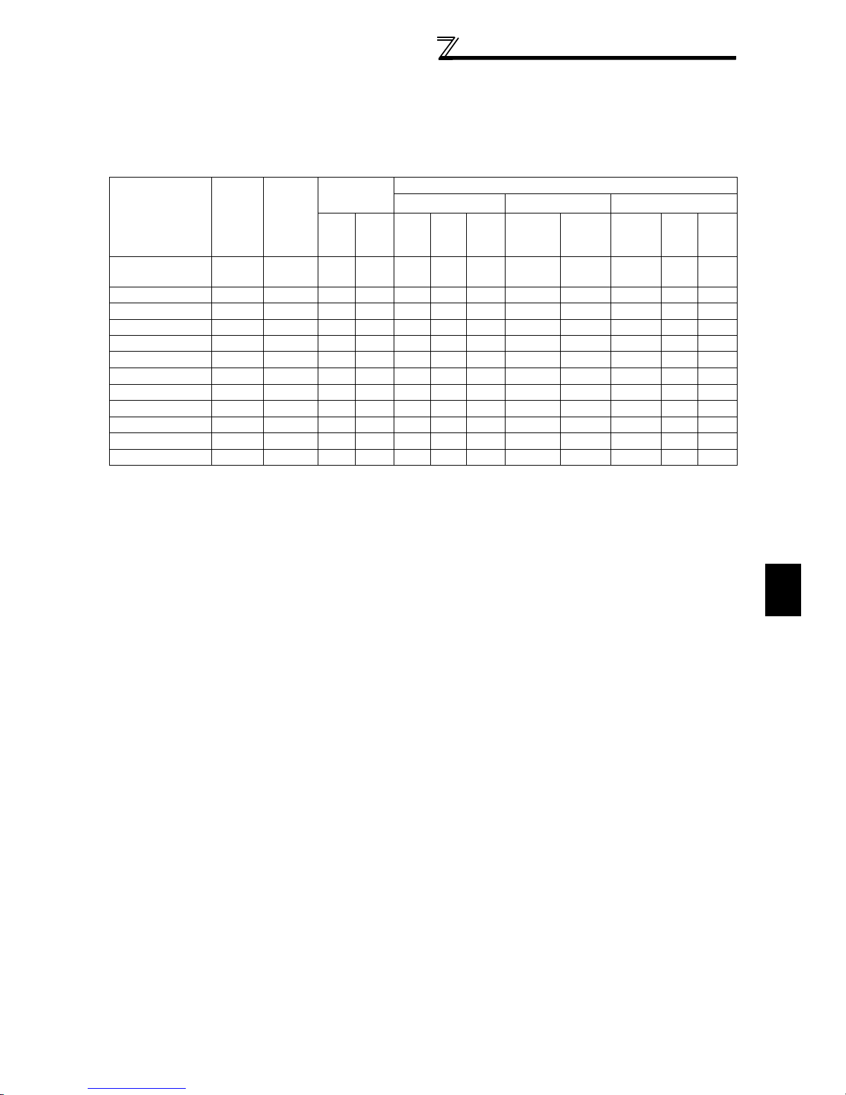
Check the motor capacity of the inverter you purchased. Appropriate peripheral devices must be selected according to the
capacity. Refer to the following list and prepare appropriate peripheral devices:
200V class
Motor
Output
(kW(HP))
*1
Applicable Inverter Type
Breaker Selection
Reactor connection
without with
*2
with commercial
power-supply
operation
0.75 (1) FR -F 720-0 0046-NA 30AF 10A 30AF 10A 30AF 10A S-N10 S-N10
1.5 (2) FR-F720-00077-NA 30AF 15 A 30A F 15A 30AF 15A S-N10 S-N10
2.2 (3) FR-F720-00105-NA 30AF 20 A 30A F 15A 30AF 20A S-N10 S-N10
3.7 (5) FR-F720-00167-NA 30AF 30A 3 0AF 30A 30AF 30A S-N20, N21 S-N10
5.5 (7.5) FR-F720-00250- NA 50AF 50A 50AF 40A 50AF 50A S-N25 S-N20, N21
7.5 (10) FR-F720-00340-NA 100AF 60A 50AF 50A 100AF 60A S-N25 S-N25
11 (15) FR-F720-00490- NA 100AF 75A 100AF 75A 100AF 75A S-N35 S-N35
15 (20) FR-F720-00630-NA 225AF 125A 100AF 100A 225AF 125A S-N50 S-N50
18.5 (25) FR-F720-00770-N A 225AF 150A 2 25AF 125A 225AF 150A S- N 65 S-N50
22 (30) FR-F720-00930-NA 225AF 175A 225AF 150A 225AF 175A S-N80 S-N65
30 (40) FR-F720-01250-NA 225AF 225A 225AF 175A 225AF 225A S-N95 S-N80
37 (50) FR-F720-01540-NA 400AF 250A 225AF 225A 400AF 250A S-N150 S-N125
45 (60) FR-F720-01870-NA 400AF 300A 400AF 300A 400AF 350A S-N180 S-N150
55 (75) FR-F720-02330-NA 400AF 400A 400AF 350A 600AF 500A S-N220 S-N180
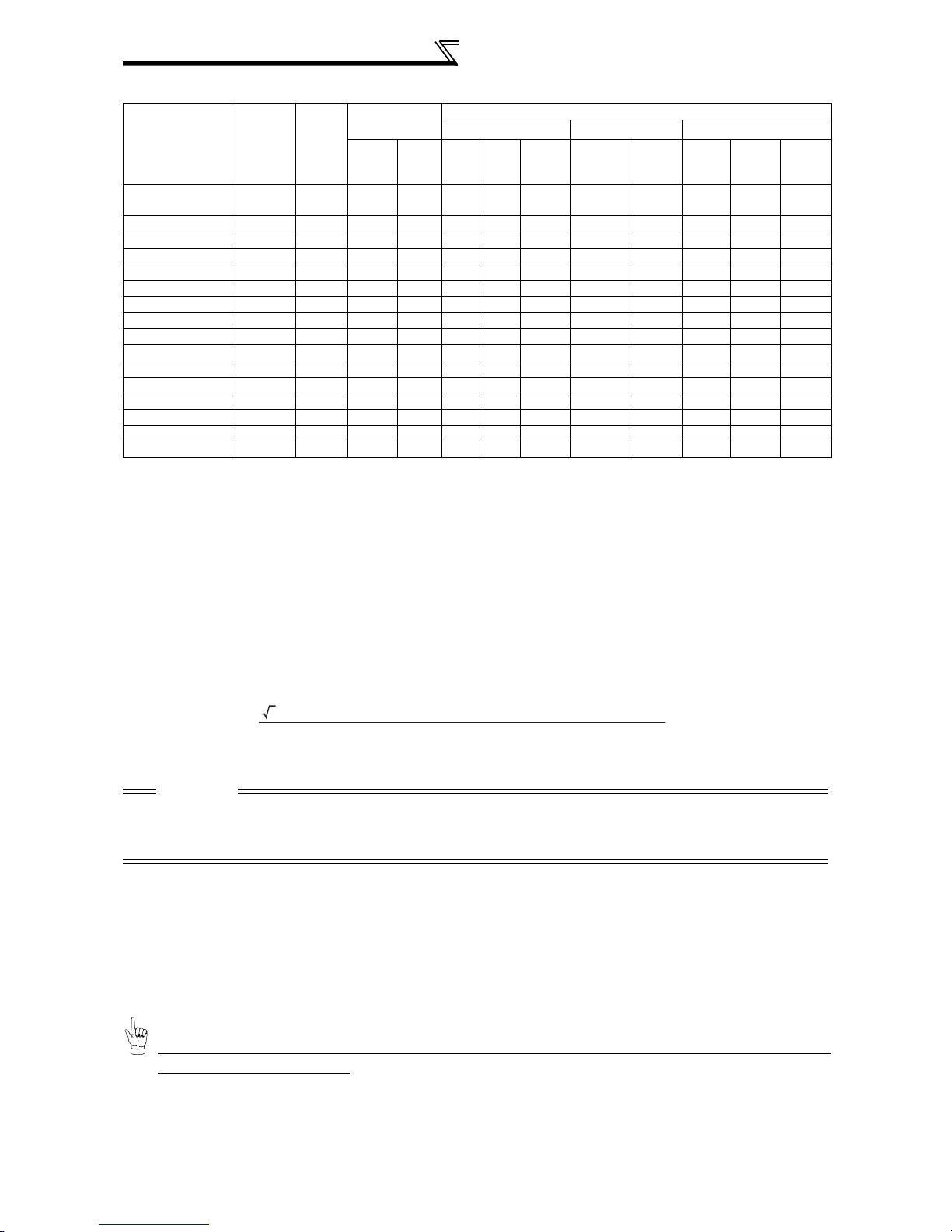
400V class
Motor
Output
(kW(HP))
*1
Applicable Inverter Type
Reactor connection
without with
Breaker Selection
0.75 (1) FR -F 740-0 0023-NA 30AF 5A 30AF 5A 30AF 5A S-N10 S -N 10
1.5 (2) FR-F740-00038-NA 30AF 10 A 30A F 10A 30AF 10A S-N10 S-N10
2.2 (3) FR-F740-00052-NA 30AF 10 A 30A F 10A 30AF 15A S-N10 S-N10
3.7 (5) FR-F740-00083-NA 30AF 20 A 30A F 15A 30AF 20A S-N10 S-N10
5.5 (7.5) FR-F740-00126-NA 30AF 30A 30AF 20A 30AF 30A S-N20 S-N11, N12
7.5 (10) FR-F740-00170-NA 30AF 30A 30AF 30A 30AF 30A S-N20 S-N20
11 (15) FR-F740-00250- NA 50AF 50A 50AF 40A 50AF 50A S-N20 S-N20
15 (20) FR-F740-00310-NA 100AF 60A 50AF 50A 100AF 60A S-N25 S-N20
18.5 (25) FR-F740-00380-NA 100AF 75A 100AF 60A 100AF 75A S-N25 S-N25
22 (30) FR-F740-00470-NA 100AF 100A 100AF 75A 100AF 100A S-N35 S-N25
30 (40) FR-F740-00620-NA 225AF 125A 225AF 100A 225AF 125A S-N50 S-N50
37 (50) FR-F740-00770-NA 225AF 150A 225AF 125A 225AF 150A S-N65 S-N50
45 (60) FR-F740-00930-NA 225AF 175A 225AF 150A 225AF 175A S-N80 S-N65
55 (75) FR-F740-01160-NA 225AF 200A 225AF 175A 225AF 200A S-N80 S-N80
75 (100) FR-F740-0180 0- N A 225AF 225A 225AF 225A S-N95
90 (125) FR-F740-0180 0- N A 225AF 225A 400AF 300A S-N150
110 (150) FR-F740-02160-NA 225AF 225A 400AF 350A S-N180
132 (200) FR-F740-02600-NA 400AF 400A 40 0AF 400A S-N220
160 (250) FR-F740-03250-NA 400AF 400A 60 0AF 500A S-N300
185 (300) FR-F740-03610-NA 400AF 400A 60 0AF 500A S-N300
*1 Selections for use of the Mitsubishi 4-pole standard motor with power supply voltage of 200/400VAC 50Hz.
*2 Select the MCCB according to the inverter power supply capacity.
Install one MCCB per inverter.
For installations in the United States or Canada, use the fuse certified by the UL and cUL.
(Refer to page 127.)
*3 The electrical durability of magnetic contactor is 500,000 times. When the magnetic contactor is used for emergency stop during motor
driving, the electrical durability is 25 times.
When using the MC for emergenc y stop d uring mot or d riving or usin g on the mot or side dur ing comme rcial-p ower su pply op erat ion , select the
MC with class AC-3 rated current for the motor rated curre nt.
*4 When the breaker on the inverter primary side trips, check for the wiring fault (short circuit), damage to internal parts of the inverter, etc.
Identify the cause of the trip, then remove the cause and power on the breaker.
*2
with commercial
power-supply
operation
Input Side Magnetic
Contactor
*3
Reactor connection
without
with
Input Side Magnetic
Contactor
*3
Reactor connection
without
MCCB INV
MCCB INV
with
IM
IM
3
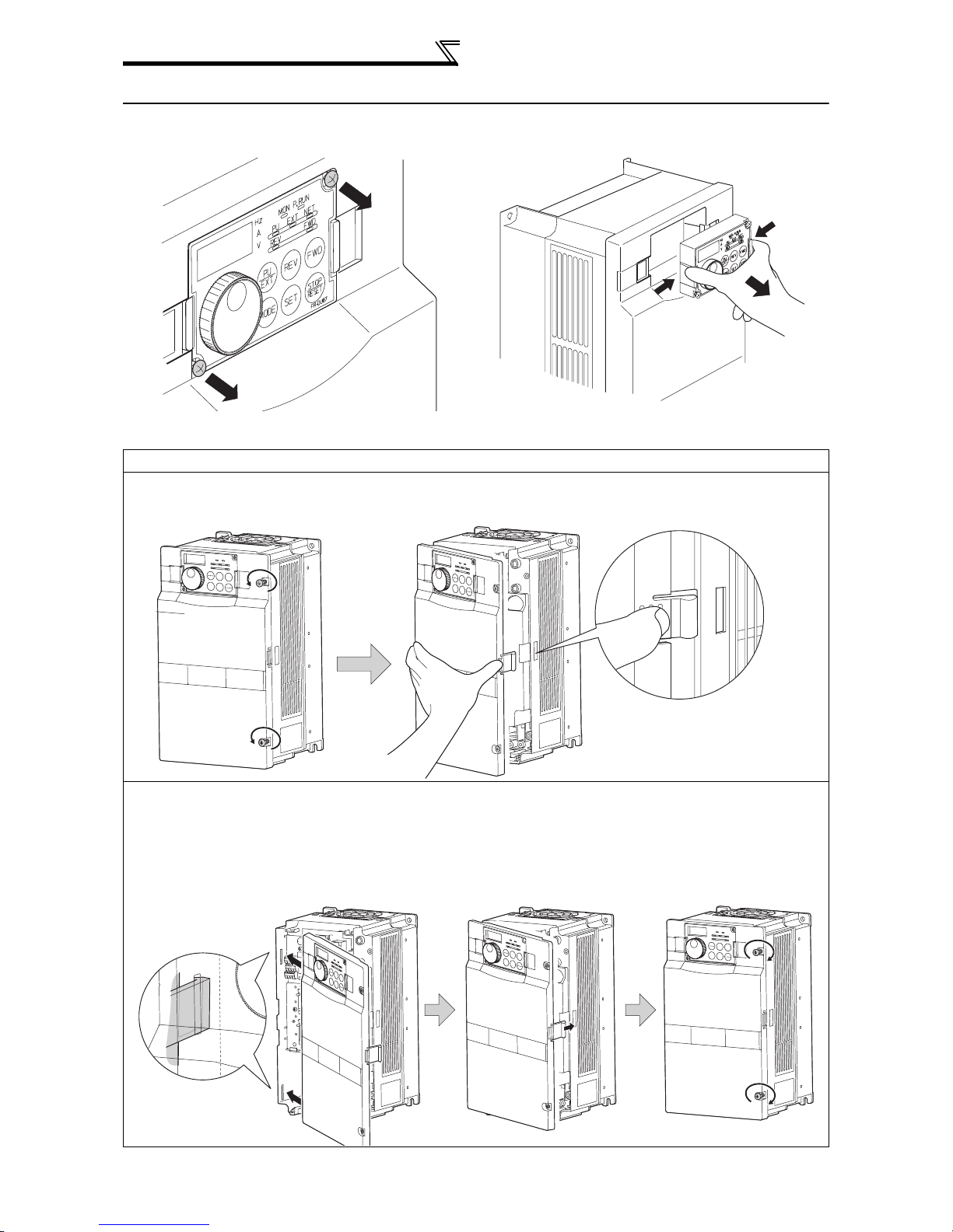
Method of removal and reinstallation of the
Installation hook
Front cover
Front cover
1) Loosen the installation screws of the
front cover.
2) Pull the front cover toward you to remove by pushing an
installation hook using left fixed hooks as supports.
front cover
2.2 Method of removal and reinstallation of the front cover
•Removal of the operation panel
1) Loosen the two screws on the operation panel.
(These screws cannot be removed.)
When reinstalling the operation panel, insert it straight to reinstall securely and tighten the fixed screws of the
operation panel.
FR-F720-01250-NA or less, FR-F740-00620-NA or less
•
Removal
2) Push the left and right hooks of the operation panel
and pull the operation panel toward you to remove.
•Reinstallation
1) Insert the two fixed hooks on the left side of
the front cover into the sockets of the
inverter.
Front cover
4
2) Using the fixed hooks as supports,
securely press the front cover
against the inverter.
(Although installation can be done
with the operation panel mounted,
make sure that a connector is
securely fixed.)
Front cover
3) Tighten the installation
screws and fix the front
cover.
Front cover
5
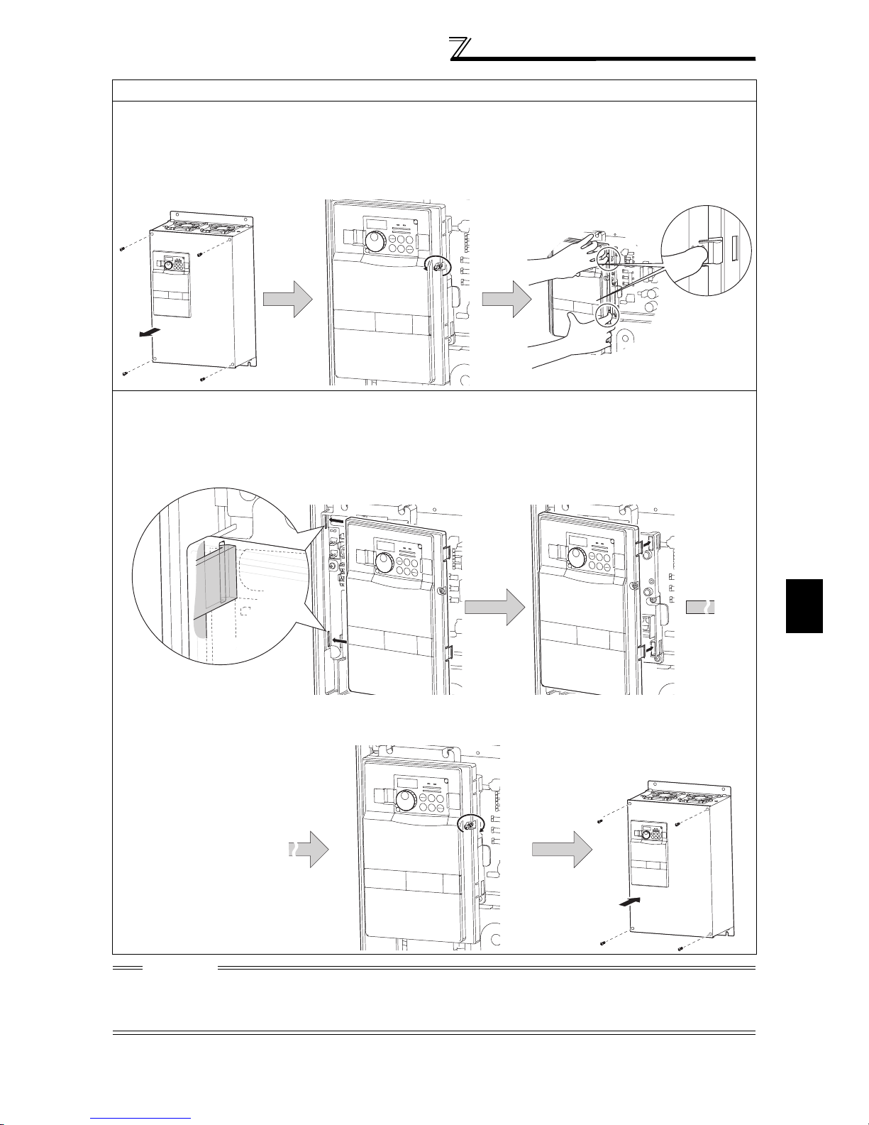
2
INSTALLATION AND WIRING
Method of removal and reinstallation of the
front cover
FR-F720-01540-NA or more, FR-F740-00770-NA or more
•
Removal
•Reinstallation
CAUTION
1. Fully make su re th at th e fr on t c ov er has be en r ei nstalled securely. Always tighten the in st al l at io n s cr ews of t he fr on t co v er.
2. The same ser ial number is printed on the capacity plat e of the front cover and the rating pl ate of the inverter. Before
reinstalling the front cover, check the serial numbers to ensure that the cover removed is reinstalled to the inverter from
where it was removed.
Front cover 2
Front cover 1
Installation hook
1) Remove installation screws on
the front cover 1 to remove the
front cover 1. (For the FR-F74003250 and 03610, six positions
are fixed with screws.)
2) Loosen the installation
screws of the front cover 2.
3) Pull the front cover 2 toward you to
remove by pushing an installation
hook on the right side using left
fixed hooks as supports.
Front cover 2 Front cover 2
Front cover 2
Front cover 1
1) Insert the two fixed hooks on the left side of the
front cover 2 into the sockets of the inverter.
2) Using the fixed hooks as supports, securely
press the front cover 2 against the inverter.
(Although installation can be done with the
operation panel mounted, make sure that a
connector is securely fixed.)
3) Fix the front cover 2 with the
installation screws.
4) Fix the front cover 1 with the
installation screws. (For the FR-F74003250 and 03610, fix six positions with
screws.)
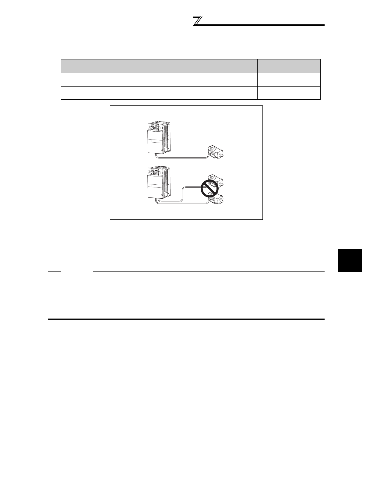
Installation of the inverter and instructions
CAUTION
When encasing multiple inverters, install them in parallel
(leave 5cm (1.97 inches) or more clearance) as a
cooling measure.
*1cm (0.39 inches) or more for FR-F720-00167,
FR-740-00083 or less
2.3 Installation of the inverter and instructions
• Installation of the Inverter
Installation on the enclosure
FR-F720-01250 or less
FR-F740-00620 or less
• Install the inverter under the following conditions.
Vertical mounting
Vertical
• The inverter consists of precision mechanical and electronic p art s. Never instal l or han dle i t in any of the follo wing
conditions as doing so could cause an operation fault or failure.
FR-F720-01540 or more
FR-F740-00770 or more
Measurement
position
5cm
(1.97inches)
Measurement
position
Temperature: -10°C to 50°C (14°F to 122°F)
(LD)
-10°C to 40°C (14°F to 104°F)
(SLD)
Ambient humidity: 90% RH maximum
Inverter
5cm
(1.97inches)
5cm
(1.97inches)
Leave enough clearances and take
cooling measures.
5cm (1.97 inches) or more
FR-F720-02330 or less
FR-F740-01160 or less
5cm
(1.97inches)
or more *
10cm
or more
5cm
(1.97inches)
or more *
10cm
or more
ClearancesAmbient temperature and humidity
(3.94inches)
10cm
(3.94inches)
or more
(3.94inches)
FR-F740-01800 or more
20cm (7.87inches)
or more
10cm
(3.94inches)
or more
20cm (7.87inches)
or more
Direct sunlight Vibration
Vertical mounting
(When installing two or
more inverters, install
them in parallel.)
6
(5.9m/s
2
or more)
High temperature,
high humidity
Oil mist, flammable
Transportation by
holding the front cover
gas, corrosive gas,
fluff, dust, etc.
Horizontal placement
Mounting to
combustible material

2
INST ALLATION AND WIRING
Installation of the inverter and instructions
Wiring cover and Handling (FR-F720-00930 (FR-F740-00620) or less)
1) When cable conduits are not connected
Cut the protective bushes of the wiring cover with nippers or a cutter before running the cables.
Wiring cover
Protective bush
WARNING
Do not remove the protective bushes. Otherwise, the cable sheathes may be scratched by the wiring cover
edges, resulting in a short circuit or ground fault.
2) When cable conduits are connected
Remove the corresponding protective bushes and connect the cable conduits.
REMARKS
⋅ When using conduits for the FR-F720-00046 and 00077, fix the conduits to the wiring cover after connecting the earth cable
to the inverter earth term in al.
7
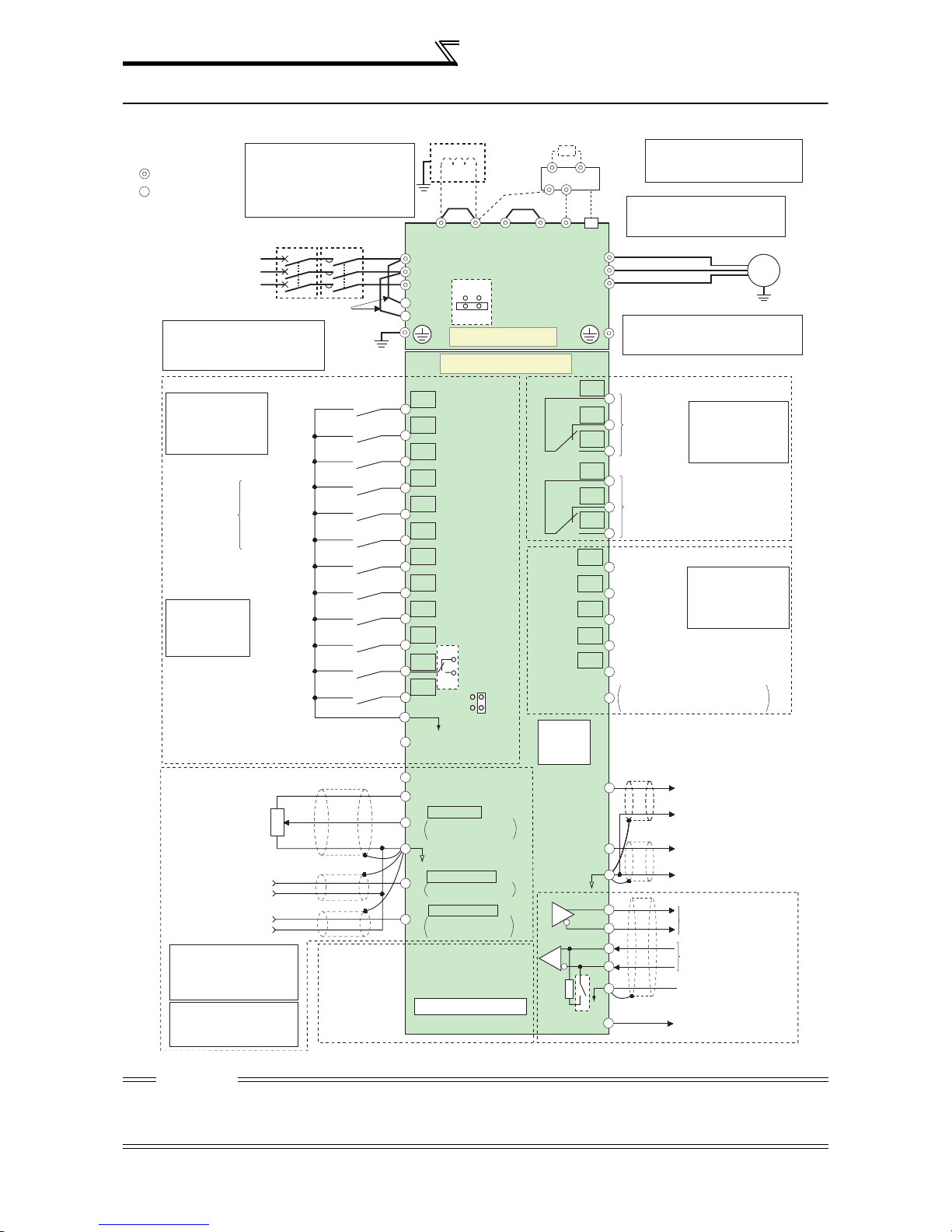
Wiring
Three-phase AC
power supply
MCCB
Jumper
R/L1
S/L2
T/L3
R1/L11
S1/L21
PC
10E(+10V)
10(+5V)
2
3
1
1
4
Control input signals (No voltage input allowed)
Jumper
Motor
Relay output 1
(Alarm output)
C1
B1
A1
U
V
W
AM
5
*1
Main circuit terminal
Control circuit terminal
MC
Main circuit
Control circuit
C2
B2
A2
Relay output 2
Relay output
IM
AU
PTC
TXD+
TXD-
RXD+
RXD-
SG
SINK
SOURCE
Terminal functions
vary with the output
terminal assignment
(Pr. 195, Pr. 196)
Terminal functions
vary with the output
terminal assignment
(Pr. 190 to Pr. 194)
Terminal functions
vary with the input
terminal assignment
(Pr. 178 to Pr. 189)
*3
STF
STR
STOP
RH
RM
RL
JOG
RT
MRS
RES
AU
CS
SD
RUN
SU
IPF
OL
FU
SE
Connector for
with/without
EMC filter
ON
OFF
VCC
Frequency setting signal (Analog)
Frequency setting
potentiometer
1/2W1k
Ω
Auxiliary input
(+)
(-)
2
(Analog common)
0 to 5VDC
0 to 10VDC
selected
4 to 20mADC
*
4
5
PU
connector
Terminal 4 input
(Current input)
Terminating
resistor
Connector
for plug-in option
connection
*
5. It is recommended to use
2W1kΩ when the
frequency setting signal is
changed frequently.
(+)
(-)
0 to 5VDC
0 to 10VDC
selected
*
4
GND
RS-485 terminals
Data transmission
Data reception
4 to 20mADC
*
4
selected
0 to ±5VDC
0 to ±10VDC
(-)
(+)
(0 to 10VDC)
Analog signal output
Frequency detection
Open collector output common
Sink
/source common
Running
Up to frequency
Instantaneous
power failure
Overload
Open collector output
Terminal 4 input selection
(Current input selection)
Selection of automatic restart
after instantaneous
power failure
Output stop
Reset
*3. AU terminal
can be used
as PTC input
terminal.
Middle speed
High speed
Low speed
Jog mode
Second function selection
Multi-speed
selection
Forward
rotation
start
Reverse
rotation
start
Start self-holding selection
PR*7
PX*7
Jumper
*7.
*5
*
4. Terminal input
specifications can be
changed by analog input
specifications switchover
(Pr. 73, Pr. 267).
(Permissible load
current 100mA)
5V
*2. To supply power to the
control circuit separately,
remove the jumper across
R1/L11 and S1/L21.
*2
Please do not remove or use
terminals PR and PX or the
jumper connected.
N/-
P/+
Option connector 1
P1
Brake resistor
(Option)
Brake unit
(Option)
CN8
*6
Sink logic
Ground
Ground
Ground
(0 to 20mADC)
(-)
(+)
CA
(0 to 20mADC)
(-)
(+)
CA
(0 to 20mADC)
Analog current output
(-)
(+)
CA
24VDC power supply
(Common for external power supply transistor)
Contact input common
*6. The CN8 connector is
provided for
the FR-F740-01800 or more.
*1.
DC reactor (FR-HEL)
The DC reactor supplied with the
FR-F740-01800 or more should be
connected to these terminals. When
a DC reactor is connected, remove the
jumper across P1-P/+ for the 200V class
and FR-F740-01160 or less.
*8.
The FR-F720-00046 and 00077
are not provided with the ON/OFF
connector of the EMC filter.
*8
2.4 W iring
2.4.1 Terminal connection diagram
CAUTION
· To prevent a malfunction due to noise, keep the signal cables more than 10cm (3.94inches) away from the power cables.
· After wiring, wire offcuts must not be left in the inverter.
Wire offcuts can cause an alarm , fail ur e or malfunction. Always keep the inverter clean.
When drilling mounting holes in an enclosure etc., take care not to allow chips and other foreign matter to enter the inverter.
8
2
INST ALLATION AND WIRING
2.4.2 Specification of main circuit terminal
Wiring
Terminal
Symbol
R/L1,
S/L2,
T/L3
Terminal Name Description
Connect to the commercial power supply.
AC power input
Keep these te rminals ope n when using t he high power factor co nverter
(FR-HC, MT - HC) or pow er rege neratio n common conve rte r (FR-CV ).
U, V, W Inverter output Connect a three-phase squirrel-cage motor.
Connected to the AC power supply terminals R/L1 and S/L2. To retain
the alarm display and alarm output or when using the high power factor
converter (FR-HC, MT-HC) or power regeneration common converter
(FR-CV), remove the jumpers from terminals R/L1-R1/L11 and S/L2S1/L21 and apply external power to these terminals.
R1/L11,
S1/L21
Power supply for
control circuit
Do not turn off the power supply for control circuit (R1/L1 1, S1/L21) with
the main circuit power (R/L1, S/L2, T/L3) on. Doing so may damage the
inverter. The circuit should be configured so that the main circuit power
(R/L1, S/L2, T/L3) is also turned off when the power supply for control
circuit (R1/L11, S1/L21) is off.
FR-F720-00770 (FR-F740-00380) or less : 60VA,
FR-F720-00930 to 02330 (FR-F740-00470 to 03610) : 80VA
Connect the br ake un it ( FR-B U, BU and MT-BU5), power
P/+, N/-
Brake unit
connection
regeneration common converter (FR-CV), high power factor
converter (FR -H C and MT-HC) or power regener at i on conv ert er (MT RC).
For the FR-F720-02330 or less, FR-F740-01160 or less, remove the
jumper across terminals P/+ - P1 and connect the DC reactor. (For
the FR-F740-01800 or more, a DC reactor is supplied as standard.)
P/+, P1
DC reactor
connection
PR, PX Please do not remove or use terminals PR and PX or the jumper connected.
Ground For grounding the inverter chassis. Must be grounded.
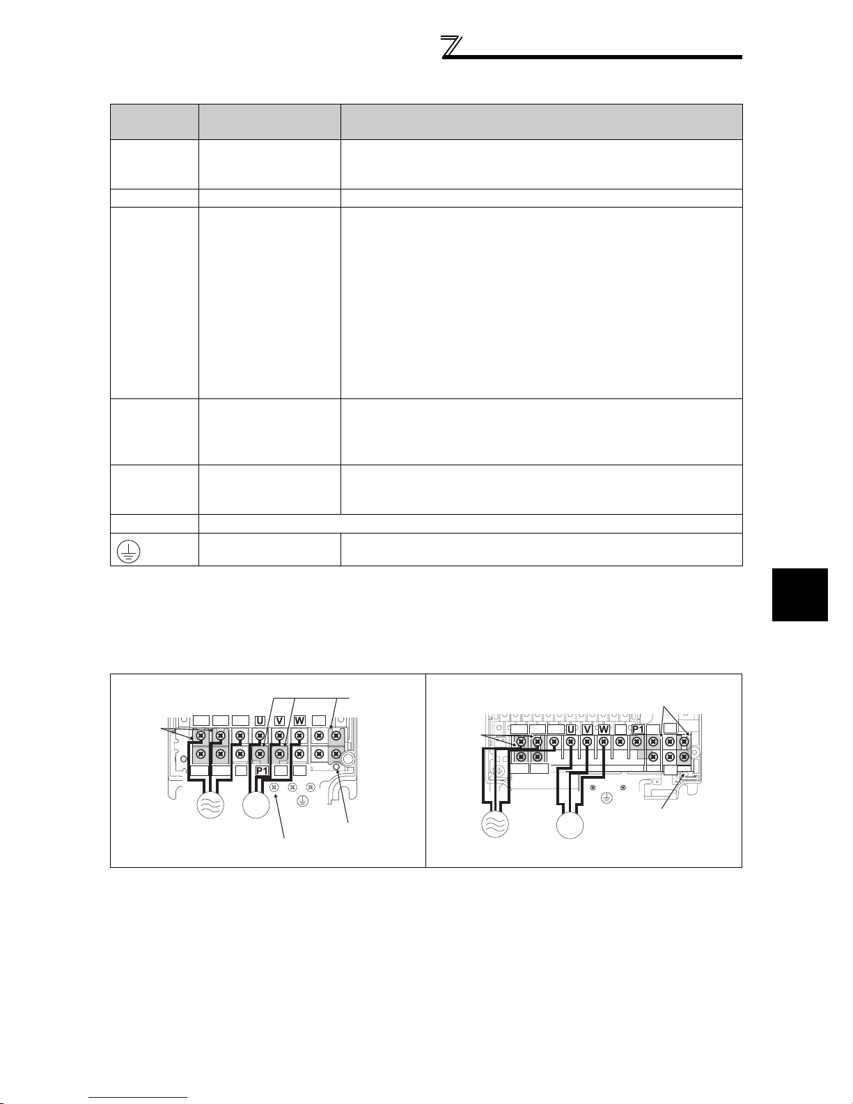
2.4.3 Terminal arrangement of the main circuit terminal, power supply and the
motor wiring.
200V class
FR-F720-00046, 00077-NA FR-F720-00105 to 00250-NA
Jumper
Screw size (M4)
R/L1
S/L2
T/L3
PR
Jumper
Jumper
Screw size (M4)
R/L1 S/L2 T/L3
N/-
Jumper
PR
P/+
R1/L11
S1/L21
Power supply
N/-
IM
Motor
As this is an inside cover fixing screw,
do not remove it.
PX
P/+
Screw size
(M4)
Charge lamp
R1/L11 S1/L21
Power supply
IM
Motor
Screw size
(M4)
PX
Charge lamp
9
10
Wiring
FR-F720-00340, 00 490-NA FR-F720-00630-NA
FR-F720-00770 to 01 250-NA FR-F720-01540 to 02 330-NA
R/L1 S/L2 T/L3
N/-
P/+
PR
PX
R1/L11 S1/L21
IM
Screw size
(M5)
Screw size (M5)
Jumpe
r
Jumper
Charge lamp
Motor
Power supply
R1/L11 S1/L21
R/L1 S/L2 T/L3
N/-
P/+
PR
IM
Screw size
(M4)
Screw size (M5)
Screw size (M5)
Jumper
Jumper
Charge lamp
Motor
Power supply
R/L1 S/L2 T/L3
N/-
P/+
PR
R1/L11 S1/L21
IM
Screw size (M4)
Screw size (M6)
Jumper
Jumper
Charge lamp
Motor
Power supply
Screw size
(00770:M6, 00930, 01250:M8)
R/L1 S/L2 T/L3
N/-
P/+
R1/L11 S1/L21
IM
Screw size
(M4)
Jumper
Jumper
Charge lamp
Motor
Power
supply
Screw size
(01540:M6,
01870, 02330:M8)
Screw size
(01540:M8, 01870, 02330:M10)
2
INST ALLATION AND WIRING
400V class
r
R1/L11 S1/L21
R/L1 S/L2 T/L3
N/-
P/+
PR
IM
Screw size
(M4)
Screw size (M5)
Screw size (M5)
Jumper
Jumper
Charge lamp
Motor
Power supply
R/L1 S/L2 T/L3
N/-
P/+
PR
R1/L11 S1/L21
IM
Screw size (M4)
Screw size (M6)
Screw size (M6)
Jumper
Jumper
Charge lamp
Power supply
Motor
FR-F740-00023 to 00126 - NA FR-F740-00170, 00 250 -NA
Jumper
Screw size (M4)
R/L1 S/L2 T/L3
N/-
Jumper
PR
P/+
Wiring
Charge lamp
R1/L11 S1/L21
Power supply
IM
Motor
Screw size
(M4)
PX
Jumper
Charge lamp
Screw size
(M4)
Power supply
FR-F740-00310, 00380 - N A R-F740-00470, 006 20-NA
R1/L11 S1/L21
R/L1 S/L2 T/L3
Screw size
(M4)
N/-
IM
Motor
P/+
PR
Jumpe
PX
11
Wiring
IM
R/L1 S/L2 T/L3
N/-
P/+
R1/L11 S1/L21
P/+
P/+
Screw size (M4)
Jumper
Charge lamp
Screw size (M10)
Screw size
(M10)
Motor
Screw size (M12)
(for option)
Power supply
DC reactor
FR-F740-00770 to 01160-NA FR-F740-01800 to 02600 - N A
R1/L11 S1/L21
Screw size(M4)
Charge lamp
Jumper
Screw size
(00770: M6
00930, 01160: M8)
Screw size (M4)
Screw size
(01800: M8, 02160: M10)
R1/L11 S1/L21
Screw size (M10)
Charge lamp
Jumper
Screw size
(01800: M8, 02160, 02600: M10)
R/L1 S/L2 T/L3
Power
supply
N/-
Screw size
(00770: M6
00930, 01160: M8)
FR-F740-03250, 03610 - N A
P/+
Jumper
IM
Motor
R/L1 S/L2 T/L3
Power
supply
N/-
DC reactor
P/+
P/+
IM
Motor
Screw size
(01800: M8,
02160, 02600: M10)
CAUTION
· T he power supply cables must be c onnected to R/L1, S/L2, T/L3. Nev er connect the power cable to th e U, V, W of the
inverter. Doing so will damage the inverter. (Phase sequence needs not to be matched.)
· Connect the motor to U, V, W. At this time, turning on the forward rotation switch (signal) rotates the motor in the
counterclockwise direction when viewed from the motor shaft.
12
13
Wiring
2
INSTALLATION AND WIRING
(1) Cable sizes etc., of the main control circuit terminals and ground terminals
Select the recommended cable size to ensure that a voltage drop will be 2% max.
If the wiring distance is long between the inverter and motor, a main circuit cable voltage drop will cause the motor
torque to decrease especially at the output of a low frequency.
The following table indicates a selection example for the wiring length of 20m (65.62feet).
200V class (when input power supply is 220V)
Applicable Inverter
Type
Terminal
Screw
Size *4
Tightening
Tor que
N·m
Crimping
Terminal
Cable Sizes
HIV, etc. (mm2) *1
AWG *2
PVC, etc. (mm2) *3
R/L1,
S/L2,
T/L3
U, V, W
R/L1,
S/L2,
T/L3
U, V , W
Ground
Cable
Gauge
R/L1, S/L2,
T/L3
U, V, W
R/L1,
S/L2,
T/L3
U, V , W
Ground
Cable
Gauge
FR-F720-00046 to
00105-NA
M4 1.5 2-4 2-4 2 2 2 14 14 2.5 2.5 2.5
FR-F720-00167-NA M4 1.5 5.5-4 5.5-4 3.5 3.5 3.5 12 12 4 4 4
FR-F720-00250-NA M4 1.5 5.5-4 5.5-4 5.5 5.5 5.5 10 10 6 6 6
FR-F720-00340-NA M5 2.5 14-5 8-5 14 8 14 6 8 16 10 16
FR-F720-00490-NA M5 2.5 14-5 14-5 14 14 14 6 6 16 16 16
FR-F720-00630-NA M5 2.5 22-5 22-5 22 22 14 4 6 (*5) 25 25 16
FR-F720-00770-NA M6 4.4 38-6 38-6 38 38 22 2 2 50 50 25
FR-F720-00930-NA M8/M6 7.8 38-8 38-8 38 38 22 2 2 50 50 25
FR-F720-01250-NA M8/M6 7.8 60-8 60-8 60 60 38 1/0 1/0 50 50 25
FR-F720-01540-NA M8/M6 7.8 80-8 80-8 80 80 38 3/0 3/0 70 70 35
FR-F720-01870-NA M10/M8 14.7 100-10 100-1 0 100 100 60 4/0 4/0 95 95 50
FR-F720-02330-NA M10/M8 14.7 100-10 100-1 0 100 100 60 4/0 4/0 95 95 50
*1 The recommended cable size is that of the cable (e.g. HIV cable (600V class 2 vinyl-insulated cable)) with continuous maximum permissible
temperature of 75
°C (167°F)
. Assumes that the ambient temperature is 50
°C (122°F)
or less and the wiring distance is 20m
(65.62feet)
or less.
*2 The recommended cable size is that of the cable (THHW cable) with continuous maximum permissible temperature of 75°C (167°F).
Assumes that the ambient temperature is 40°C
(104°F) or less and the wiring distance is 20m (65.62feet) or less.
*3 For the FR-F720-00930 or less, the recommended cable size is that of the cable (PVC cable) with continuous maximum permissible
temperature of 70°C
(158°F). Assumes that the ambient temperature is 40°C (104°F) or less and the wiring distance is 20m(65.62feet) or
less.
For the FR-F720-01250 or more, the recommended cable size is that of the cable (XLPE cable) with continuous maximum permissible
temperature of 90°C
(194°F). Assumes that the ambient temperature is 40°C (104°F) or less and wiring is performed in an enclosure.
*4 The terminal screw size indicates the terminal size for R/L1, S/L2, T/L3, U, V, W, and a screw for grounding. For the FR-F720-00930 to
02330, screw sizes are different. (R/L1, S/L2, T/L3, U, V, W, and a screw for grounding)
*5 When connecting the option unit to P/+, P1, N/-, use THHN cables for t he option and terminals R/L1, S/L2, T/L3, U, V, W.
Wiring
3 × wire resistance[mΩ/m] × wiring distance[m] × current[A]
1000
400V class (when input power supply is 440V based on the rated current for 110% overload for 1 minute)
Crimping
*4
Tightening
Torque
N·m
Terminal
R/L1,
S/L2,
T/L3
U, V,
W
HIV, etc. (mm2) *1
R/L1,
U, V,
S/L2,
W
T/L3
Ground
Cable
Gauge
M4 1.5 2-4 2-4 2 2 2 14 14 2.5 2.5 2.5
Applicable
Inverter Type
FR-F740-00023 to
00083-NA
Terminal
Screw
Size
FR-F740-00126-NA M4 1.5 2-4 2-4 2 2 3.5 12 14 2.5 2.5 4
FR-F740-00170-NA M4 1.5 5.5-4 5.5-4 3.5 3.5 3.5 12 12 4 4 4
FR-F740-00250-NA M4 1.5 5.5-4 5.5-4 5.5 5.5 8 10 10 6 6 10
FR-F740-00310-NA M5 2.5 8-5 8-5 8 8 8 8 8 10 10 10
FR-F740-00380-NA M5 2.5 14-5 8-5 14 8 14 6 8 16 10 16
FR-F740-00470-NA M6 4.4 14-6 14-6 14 14 14 6 6 16 16 16
FR-F740-00620-NA M6 4.4 22-6 22-6 22 22 14 4 4 25 25 16
FR-F740-00770-NA M6 4.4 22-6 22-6 22 22 14 4 4 25 25 16
FR-F740-00930-NA M8 7.8 38-8 38-8 38 38 22 1 2 50 50 25
FR-F740-01160-NA M8 7.8 60-8 60-8 60 60 22 1/0 1/0 50 50 25
FR-F740-01800-NA M8 7.8 60-8 60-8 60 60 38 1/0 1/0 50 50 25
FR-F740-02160-NA M10 14.7 100-10 100-10 80 80 38 3/0 3/0 70 70 35
FR-F740-02600-NA M10 14.7 100-10 100-10 100 125 38 4/0 4/0 95 95 50
FR-F740-03250-NA M10 14.7 100-10 100-10 125 125 38 MCM250 MCM250 120 150 70
FR-F740-03610-NA M10 14.7 150-10 150-10 150 150 38 2 ×4/0 2×4/0 2×120 2×120 2×60
*1 For the FR-F740-01160 or less, the recommended cable size is that of the cable (e.g. HIV cable (600V class 2 vinyl-insulated cable)) with continuous
maximum permissible temperature of 75°C (167°F). Assumes that the ambient temperature is 50°C (122°F) or less and the wiring distance is 20m
(65.62feet) or less.
For the FR-F740-01800 or more, the recommended cable size is that of the cable (e.g. LMFC (heat resistant flexible cross-linked polyethylene
insulated cable)) with continuous maximum permissible temperatur e of 90° C (194°F). Assumes that the ambient temperature is 50°C (122°F) or less
and wiring is performed in an enclosure.
*2 For the FR-F740-00930 or less, the recommended cable size is that of the cable (THHW cable) with continuous maximum permissible temperature
of 75°C (167°F). Assumes that the ambient temperature is 40°C (104°F) or less and the wiring distance is 20m (65.62feet) or less.
For the FR-F740-01160 or more, the recommended cable size is that of the cable (THHN cable) with continuous maximum permissible temperature
of 90°C (194°F). Assumes that the ambient temperature is 40°C (104°F) or less and wiring is performed in an enclosure.
*3 For the FR-F740-00930 or less, the recommended cable size is that of the cable (PVC cable) with continuous maximum permissible temperature of
70°C (158°F). Assumes that the ambient temperature is 40°C (104°F) or less and the wiring distance is 20m (65.62feet) or less.
For the FR-F740-01160 or more, the recommended cable size is that of the cable (XLPE cable) with continuous maximum permissible temperature
of 90°C (194°F). Assumes that the ambient temperature is 40°C (104°F) or less and wiring is performed in an enclosure.
*4 The terminal screw size indicates the terminal size for R/L1, S/L2, T/L3, U, V, W, and a screw for grounding.
Cable Sizes
AWG *2
R/L1,
S/L2,
U, V, W
T/L3
PVC, etc. (mm2) *3
R/L1,
S/L2,
U, V , W
T/L3
Ground
Cable
Gauge
The line voltage drop can be calculated by the following formula:
line voltage drop [V]=
Use a larger diameter cable when the wiring distance is long or when it is desired to decrease the voltage drop
(torque reduction) in the low speed range.
CAUTION
· Tighten th e te rmi nal screw to the specified torque.
A screw that has been tig ht en t oo loosely can cause a short circuit or malfunction .
A screw that has been tig ht en t oo tightly can cause a short circuit or malfunction du e to th e uni t bre ak age.
· Use crimping terminals with insulation sleeve t o w i re the pow e r supply and motor.
(2) Notes on grounding
• Leakage currents flow in the inverter. To prevent an electric shock, the inverter and motor must be grounded. This
inverter must be grounded. Grounding must conform to the requirements of national and local safety regulations and
electrical codes. (JIS, NEC section 25 0, IEC 536 class 1 and other applicable standards)
• Use the dedicated ground terminal to ground the inverter.
(Do not use the screw in the casing, chassis, etc.)
• Use the thickest possible ground cable. Use the cable whose size is equal to or greater than that indicated in the above
table, and minimize the cable length. The grounding point should be as near as possible to the in vert er.
To be compliant with the European Directive (Low Voltage Directive), ground the inverter according to
the instructions on page 128.
14
Wiring
2
INST ALLATION AND WIRING
(3) Total wiring length
The overall wiring length for connection of a single motor or multiple motors should be within the value in the table
below.
Pr. 72 PWM frequency selection setting
(carrier frequency)
2
3 to 15
FR-F720-00046
FR-F740-00023
300m
(984.25 feet)
200m
(656.19 feet)
FR-F720-00077
FR-F740-00038
500m
(1640.42 feet)
300m
(984.25 feet)
FR-F720-00105 or more
FR-F740-00052 or more
500m
(1640.42 feet)
500m
(1640.42 feet)
Total wiring length
(FR-F720-00077 (FR-F740-00038) or more)
500m
(1640.42feet)
or less
300m
(984.25feet)
300m
(984.25feet)
300m (984.25feet) + 300m (984.25feet)
= 600m (1968.50feet)
When driving a 400V class motor by the inverter, surge voltages attributable to the wiring constants may occur at
the motor terminals, deteriorating the insulation of the motor.
Take the following measures (1) or (2) in this case.
Connect the surge voltage suppression filter (FR-ASF-H) to the FR-F720-02330 (FR-F740-01160) or less and
the sine wave filter (MT-BSL/BSC) to the FR-F740-01800 or more on the inverter output side.
CAUTION
· Especially for long-distance wiring, the inv erte r may be affected by a charg ing cu rrent cau sed by t he stray capacitance s of the
wiring, leading to a malf unction of th e over curre nt prot ective fu nctio n or fast respo nse current limit functi on or a malfu nction or
fault of the equipmen t connected on the inverter output side . If fast-response cu rrent limit function m alfunctions, disable t his
function. (For Pr.156 Stall prevention operation selection, r efer tothe Instruction Manual (applied).)
· For details of Pr. 72 PWM frequency selection , refer to the Instruction Manual (applied).
For explanation of surge voltage sup pression filter (FR -ASF-H) a nd sine wave filter (M T-BSL/BSC), refer to th e manua l of
each option.
(4) Cable size of the control circuit power supply (terminal R1/L11, S1/L21)
· Terminal Screw Size: M4
· Cable size: 0.75mm
2
to 2mm
· Tightening torque: 1.5N·m
2
15
Wiring
2.4.4 Control circuit terminals
indicates that termina l functions can be selected from Pr. 178 to Pr. 196 (I/O terminal funct ion select ion) (Refer to the
Instruction Man ual (applied).)
(1) Input signals
Terminal
Symbol
Type
STF
STR
STOP
RH,
RM, RL
JOG
RT
MRS Output stop
RES Reset
Contact input
AU
CS
SD
PC
Terminal
Name
Forward
rotation start
Reverse
rotation start
Start selfholding
selection
Multi-speed
selection
Jog mode
selection
Second
acceleration/
deceleration
time
selection
Terminal 4
input selection
PTC input
Selection of
automatic
restart after
instantaneous
power failure
Contact input
common
(sink)
External
transistor
common,
24VDC
power supply,
contact input
common
(source)
Description
Turn on the STF signal to start forward
rotation and turn it off to stop.
Turn on the STR signal to start reverse
rotation and turn it off to stop.
Turn on the STOP signal to self-hold the start signal.
Multi-speed can be sele ct ed ac cording to the combination of
RH, RM and RL signals.
Turn on the JOG signal to select Jog oper at i on ( ini tial se tti ng)
and turn on the start signal to start Jog op er at ion.
Turn on the RT signal to select secon d acceleration/
deceleration time.
When the second function such as "second torque boost" and
"second V/F (base frequen cy) " ar e set, turning on the RT
signal selects these f unctions.
Turn on the MRS signal (20ms or more) to s to p th e inverter
output.
Use to shut off the inverter output when stopping the motor by
electromagnetic brake.
Used to reset alarm output pr ov id ed w hen protective function
is activated.
Turn on the RES signal for more than 0.1s, then turn it off.
Initial setting is for reset always. By setting Pr.75, re set can be
set to enabled only at an inverter alarm occurrence. Recover
about 1s after reset is cancelled.
T erminal 4 is made valid only when the AU signal is turned on. (The
frequency setting signal can be set between 4 and 20mA DC.)
Turning the AU signal on makes terminal 2 (voltage input) invalid.
AU terminal is used as PTC input termin al (thermal protection
of the motor). When using it as PTC input terminal, set the AU/
PTC switch to PTC.
When the CS signal is left on, the inverter restarts automatically at
power restoration. Note that restart setting is necessary for this
operation. In the init ial se ttin g, a rest ar t is disa b led .
(Refer to Pr.57 Restart coasting time, in Instruction Manual (applied).)
Common terminal for contact input terminal and terminal CA
for sink logic.
Common output terminal fo r 24 VD C 0. 1A power supply (PC
terminal).
Isolated from terminals 5 and SE.
When connecting the transistor output (open collector output),
such as a programmable controller (PLC), connect the external
power supply common for transistor output to this terminal to
prevent a malfunction caused by undesirable currents.
Can be used as 24VDC 0.1A power supply.
When source logic has been selected, this terminal serves as
NO contact input common.
When the STF and
STR signals are turned
on simultaneously, the
stop command is given.
Rated
Specifications
Input resistance
4.7kΩ
Voltage at
opening: 21 to
27VDC
Contacts at
short-circuited: 4
to 6mADC
-------------------- —
Power supply
voltage range
19.2 to 28.8VDC
Current
consumption
100mA
Refer to
42
Instruction
Manual
(applied).
44
Instruction
Manual
(applied).
Instruction
Manual
(applied).
Instruction
Manual
(applied).
74
48
Instruction
Manual
(applied).
Instruction
Manual
(applied).
22
16
Wiring
2
INST ALLATION AND WIRING
Terminal
Symbol
Type
10E
10
2
4
Frequency setting
1
5
Terminal
Name
Frequency
setting
power
supply
Frequency
setting
(voltage)
Frequency
setting
(current)
Frequency
setting
auxiliary
Frequency
setting
common
(2) Output signals
Description
When connecting the frequency setting potentiometer at an
initial status, connect it to termi nal 10.
Change the input specifications when connecting it to terminal
10E. (Refer to Pr.73 Analog input selection in the Instruction
Manual (applied).)
Inputting 0 to 5VDC (or 0 to 10V, 0 to 20mA) provides the
maximum output frequency at 5V (10V, 20m A) and makes
input and output proportional. Use Pr.73 to switch from among
input 0 to 5VDC (initial setting), 0 to 10VD C, and 0 to 20mA.
Inputting 0 to 20mADC (or 0 to 5V, 0 to 10V) provides the
maximum output freque ncy at 20mA (5V, 10V) ma kes input
and output proportional. This input signal is valid only when the
AU signal is on (terminal 2 input is invalid). Use Pr. 267 to
switch between the input 0 t o 20m A (initial value) and 0 to
5VDC, 0 to 10VDC. (Refer t o t he Instruction Manual (applied). )
Inputti ng 0 t o 5 VDC or 0 to 1 0VDC adds t hi s si gn al to t er mi nal
2 or 4 frequency setting signal. Use Pr.73 to switch between
the input 0 to ±5VDC and 0 to ±10VD C (init i al set t ing) .
Common terminal for frequency setting signal (terminal 2, 1 or
4) and analog output terminal AM. Do not ground.
Rated
Specifications
DC10V
Permissible load
current 10mA
DC5V
Permissible load
current 10mA
Voltage input:
Input resistance
10kΩ ± 1kΩ
Maximum
permissible
voltage 20VDC
Current input:
Input resistance
250Ω ± 2%
Maximum
permissible
current 30mA
Input resistance
10kΩ ± 1kΩ
Maximum
permissible voltage
± 20VDC
-------------------- ------
Refer to
Instruction
Manual
(applied).
38, 46
38, 46
40, 48
Instruction
Manual
(applied).
Terminal
Symbol
Type
A1,
B1,
C1
Relay
A2,
B2,
C2
RUN
SU
OL Overloa d al ar m
Open collector
IPF
FU
SE
Terminal
Name
Relay output 1
(alarm ou tput)
Relay output 2 1 changeover Contact output
Inverter
running
Up to
frequency
Instantaneous
power failure
Frequency
detection
Open collector
output common
Description
1 changeover cont act output indicates that the inverter
protective function has activated and the output stopped.
Abnormal: No conduction across B-C (Across A-C
Continuity), Normal: Across B-C Continuity (No conduction
across A-C)
Switched low when the inverter output
frequency is equal to or higher than th e
starting frequency (initial value 0.5Hz).
Switched high during stop or DC
injection brake operation.
Switched low when the output fr equency
reaches within the range of ±10% (initial
value) of the set frequency. Switched
high during acceleration/decelera tion
and at a stop.
Switched low when stall prevention is
activated by the stall prevention
function. Switched high when stall
prevention is cancelled.
Switched low when an instantaneous
power failure and under vol tage
protections are activated.
Switched low when the inverter
output frequency is equal to or higher
than the preset detected frequency
and high when less than the pre se t
detected frequency.
Common terminal for terminals RUN, SU, OL, IPF, FU -------------------- -----
*1
*1
Alarm code (4bit)
output (Refer to the
Instruction Manual
(applied).)
*1
*1
*1
Rated
Specifications
Contact
capacity:
230VAC 0.3A
(Power
factor=0.4)
30VDC 0.3A
Permissible load
24VDC 0.1A
(A voltage drop
is 3.4V
maximum when
the signal is on.)
Refer to
Instruction
Manual
(applied).
Instruction
Manual
(applied).
Instruction
Manual
(applied).
Instruction
Manual
(applied).
Instruction
Manual
(applied).
Instruction
Manual
(applied).
Instruction
Manual
(applied).
17
Wiring
Terminal
Symbol
Type
CA
Analog
AM
*1 Low indicates that the open collector output transistor is on (c onducts).
High indicates that the transis tor is off (does not conduct).
*2 Not output during inverter reset.
Terminal
Name
Analog current
output
Analog voltage
output
Description
Select one e.g. output frequency
from monitor items.
The output signal is proporti onal to
the magnitude of the corresponding
monitoring item.
*2
(3) Communication
Terminal
Symbol
Type
PU
connector
TXD+
RS-485
TXDRXD+
RXD-
RS-485 terminals
SG Ground
Terminal
Name
PU
connector
Inverter
transmission
terminal
Inverter
reception
terminal
Description
With the PU connector, communication can be made through RS-485.
(for conne ction on a 1:1 basis only)
. Conforming standard : EIA-485(RS -4 85)
. Transmission format : Multidrop
. Communication speed : 4800 to 38400bps
. Overall length : 500m (1640.42feet)
With the RS-485 terminals, communication can be made through RS-485.
Conforming standard : EIA-485(RS-485)
Transmission format : Multid ro p link
Communication speed : 300 to 38400bps
Overall length : 500m (1640.42feet)
(4) Control circuit terminal layout
Terminal screw size: M3.5
Tightening torque: 1.2N·m
A1 B1 C1 A2 B2 C2 10E 10 2 5 4
Output item:
Output frequency
(initial setting)
Rated
Specifications
Load impedance
200Ω to 450Ω
Output signal 0 to
20mADC
Output signal 0
to 10VDC
Permissible load
current 1mA
(load impedance
10kΩ or more)
Resolution 8 bit
Rated
Specifications
Refer to
Instruction
Manual
(applied)
Instruction
Manual
(applied).
Refer to
23
24
AURTRHRMRL
CA
MRS
STOP
1AMSDRES
PCCSJOGSTRSTFSDSDFUOLIPFSURUNSE
(5) Wiring instructions
1) Terminals 5, PC and SE are common to the I/O signals and isolated from each other. Do not ground.
2) Use shielded or twisted cables for connection to the control circuit terminals and run them away from the main
and power circuits (including the 200V relay sequence circuit).
3) Use two or more parallel micro-signal contacts or twin
contacts to prevent a contact faults when using contact inputs
since the control circuit input signals are micro-currents.
Micro signal contacts Twin contacts
4) Do not apply a voltage to the contact input terminals (e.g. STF) of the control circuit.
5) Always apply a voltage to the alarm output terminals (A, B, C) via a relay coil, lamp, etc.
6) It is recommended to use the cables of 0.75mm
If the cable gauge used is 1.25mm
2
or more, the front cover may be lifted when there are many cables running
or the cables are run improperly, resulting in an operation panel contact fault.
7) The wiring length should be 30m (98.43feet) maximum.
2
gauge for connection to the control circuit terminals.
18
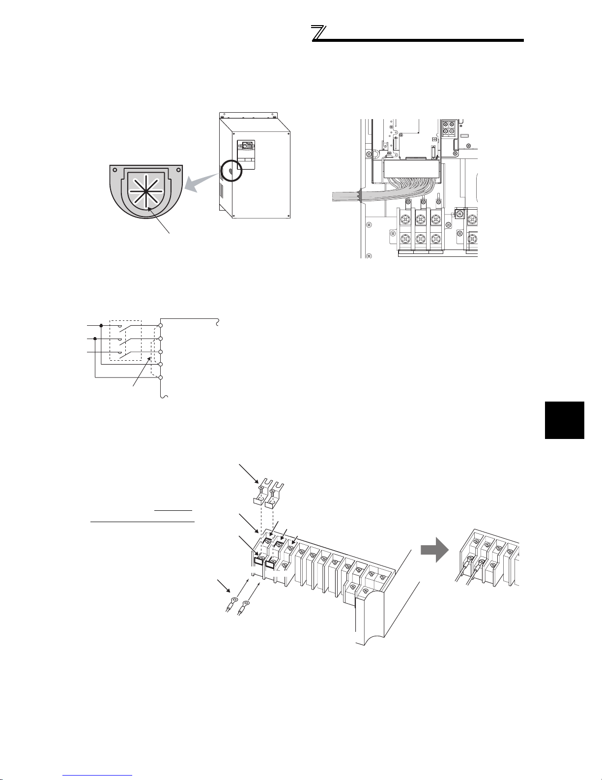
Wiring
2
INST ALLATION AND WIRING
Inverter
MC
R/L1
S/L2
T/L3
R1/L11
S1/L21
Remove the jumper
Wiring of the control circuit of the FR-F740-01800 or more
For wiring of the control circuit of the FR-F740-01800 or more, separate away from wiring of the main circuit.
Make cuts in rubber bush of the inverter side and lead wires.
<Wiring>
Rubber bush
(view from the inside)
Make cuts along the lines inside with
a cutter knife and such.
(6) When connecting the control circuit and the main circuit separately to the power supply
(separate power)
<Connection diagram> When the protected circuit is activated, opening of the electromagnetic
contactor (MC) on the inverter power supply side results in power loss in
the control circuit, disabling the alarm output signal retention. Terminals
R1/L11 and S1/L21 are provided to hold an alarm signal. In this case,
connect the power supply terminals R1/L11 and S1/L21 of the control
circuit to the primary side of the MC.
• FR-F720-00046 to 00250-NA, FR-F740-00023 to 00126-NA
1)Loosen the upper screws.
2)Remove the lower screws.
3)Remove the jumper
4)Connect the separate
power supply cable for the
control circuit to the lower
terminals (R1/L11, S1/L21).
3)
1)
2)
R1/L11
4)
R/L1
S/L2
T/L3
S1/L21
Main circuit terminal block
R1/L11
S1/L21
19
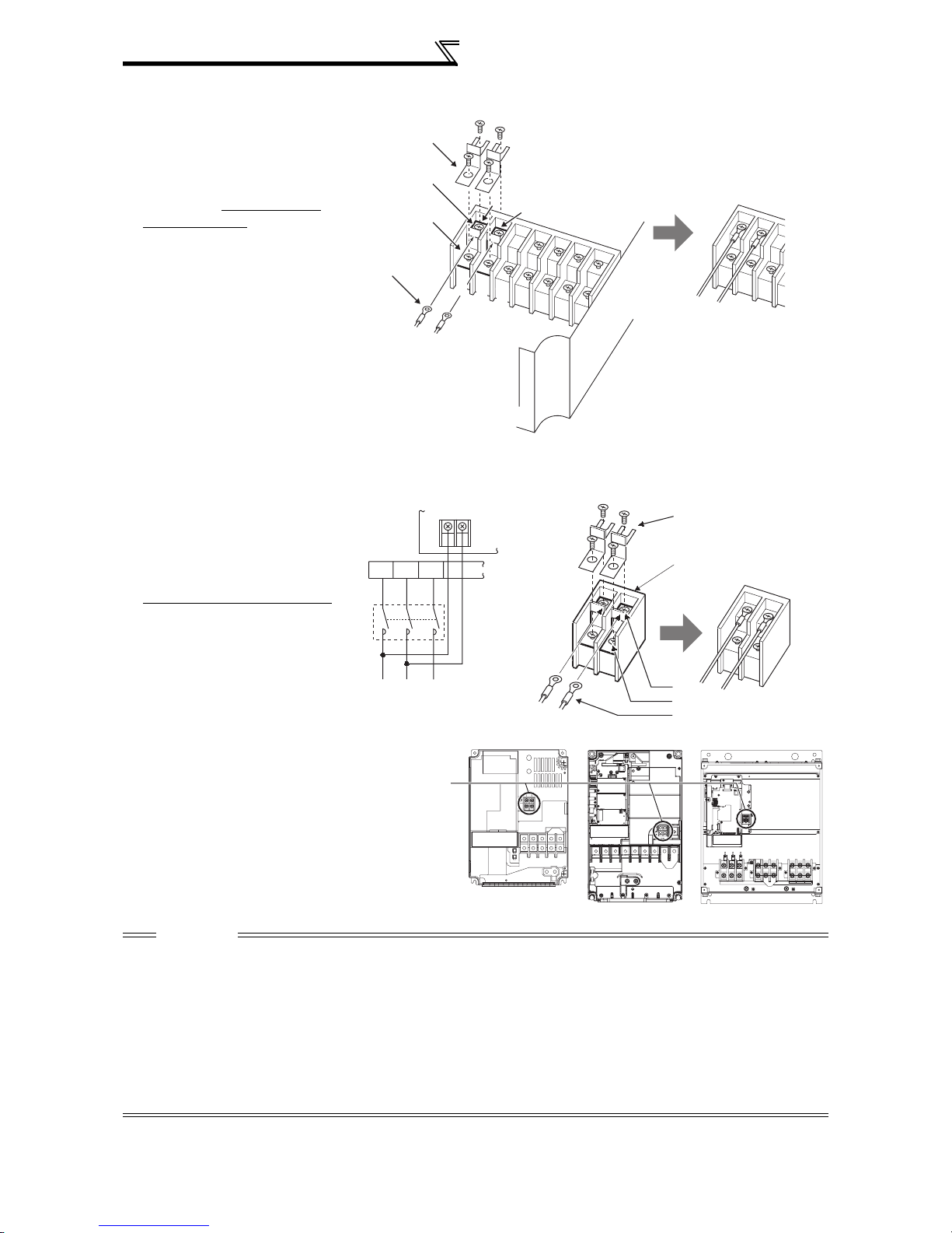
Wiring
S1/L21
R1/L11
3)
4)
1)
2)
Power supply
terminal block for
the control circuit
Power supply terminal block
for the control circuit
R/L1
S/L2
T/L3
R1/
L11
S1/
L21
Power supply
terminal block
for the control circuit
Main power supply
MC
VUW
FR-F720-00630
FR-F740-00310, 00380
FR-F720-00770 to 01250
FR-F740-00470, 00620
FR-F720-01540 or mor e
FR-F740-00770 or mor e
•FR-F720-00340, 00490-NA, FR-F740-00170, 00250-NA
1)Remove the upper screws.
2)Remove the lower screws.
3)Remove the jumper.
4)Connect the separate power
supply cable for the control
circuit to the upper terminals
(R1/L11, S1/L21).
3)
1)
R1/L11
2)
S1/L21
R1/L11
S1/L21
4)
R/
S/
L1
T/
L2
L3
Main circuit
terminal block
• FR-F720-00630-NA or more, FR-F740-00310-NA or more
1)Remove the upper screws.
2)Remove the lower screws.
3)Pull the jumper toward you to
remove.
4)
Connect the separate power supply
cable for the control circuit to the
upper terminals (R1/L11, S1/L21)
Never connect the power cable to
the terminals in the lower stand.
Doing so will damage the inverter.
.
CAUTION
1. Do not turn off the co ntro l po wer ( term inals R1/L11 and S1/L21) with the main cir cuit powe r (R /L1, S /L2, T/L 3) o n. Do ing
so may damage the inve rt er.
2. Be sure to use the inverter with the jumpers across terminals R/L1-R1/L11 and S/L2-S1/L21 removed when supplying
power from other sources. The inverter may be damaged if you do not remove the jumper.
3. Th e voltage sho uld be the sa me as that of the mai n cont rol circuit when the co ntrol circ uit power is sup plied from othe r than the
primary side of the MC.
4. Th e power capacity is 60VA or mo re for FR - F720- 00770 (FR-F740-00380) or 80VA or more for FR-F720-00930 to 02 330 (FRF740-00470 to 03610) when separate power is supplied from R1/L1 1, S1/L21.
5. When the power supp ly use d with the contr ol circui t is different fro m the one us ed wit h the mai n circuit , make up a circu it
which will switch off the main circuit power supply terminals R/L1, S/L2, T/L3 when the control circuit power supply
terminals R1/L11, S1/L21 are switched off.
20
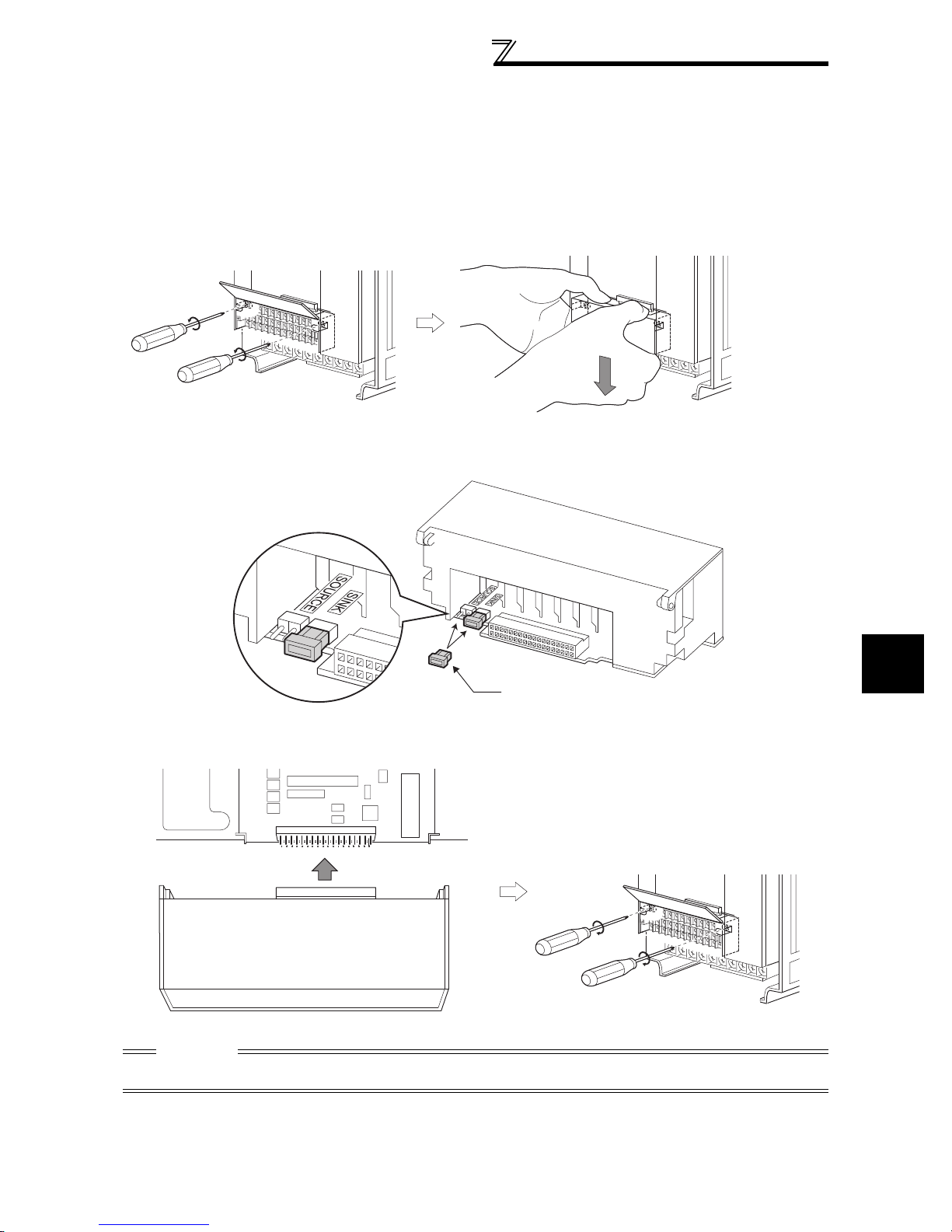
Wiring
2
INST ALLATION AND WIRING
Jumper connector
(7) Control logic switchover
The input signals are set to sink logic (SINK) when shipped from the factory.
To change the control logic, the jumper connector on the back of the control circuit terminal block must be moved to
the other position.
(The output signals may be used in either the sink or source logic independently of the jumper connector position.)
1) Loosen the two installation screws in both ends of the control circuit terminal block. (These screws cannot be
removed.)
Pull down the terminal block from behind the control circuit terminals.
2)Change the jumper connector set to the sink logic (SINK) on the rear panel of the control circuit terminal block to
source logic (SOURCE).
3)Using care not to bend the pins of the inverter's control circuit connector , reinst all the control circuit terminal block
and fix it with the mounting screws.
CAUTION
1. Make sure that the con tr ol ci rc ui t conn ector is fitted correctly.
2. While power is on, never disconnect the control circuit terminal block.
21
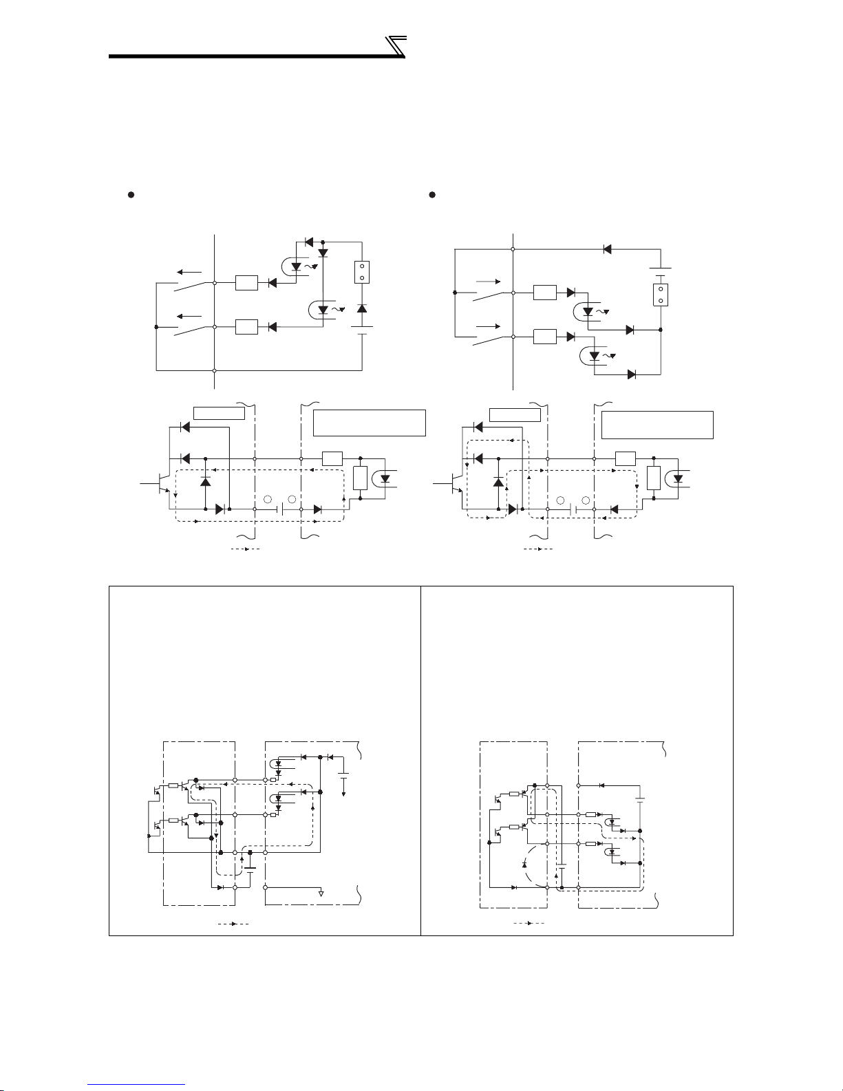
Wiring
current
PC
STF
R
STR
R
Source logic
Source
connector
current
SD
STF
R
STR
R
Sink
connector
Sink logic
Current flow concerning the input/output signal
when sink logic is selected
Current flow concerning the input/output signal
when source logic is selected
DC input (source type)
<Example: AX80>
24VDC
RUN
SE
1
9
R
Inverter
R
Current flow
+
-
+
-
DC input (sink type)
<Example: AX40>
Inverter
24VDC
RUN
SE
1
9
R
R
Current flow
4)Sink logic and source logic
⋅ In sink logic, a signal switches on when a current flows from the corresponding signal input terminal.
Terminal SD is common to the contact input signals. Terminal SE is common to the open collector output
signals.
⋅ In source logic, a signal switches on when a current flows into the corresponding signal input terminal.
Terminal PC is common to the contact input signals. Terminal SE is common to the open collector output
signals.
• When using an external power supply for transistor output
⋅ Sink logic type
Use terminal PC as a common terminal to prevent a
malfunction caused by undesirable current. (Do not
connect terminal SD of the inverter with terminal 0V
of the external power supply. When using terminals
PC-SD as a 24VDC power supply, do not install a
power supply in parallel in the outside of the inverter.
Doing so may cause a malfunction due to
undesirable current.)
22
AY40 type
transistor
output unit
1
2
9
9
10
STF
STR
24VDC
Current flow
PC
SD
⋅ Source logic type
When using a transistor power supply for transistor
output, use terminal SD as a common to prevent
misoperation caused by undesirable current.
Inverter
24VDC
(SD)
AY80 type
transistor
output unit
10
9
1
2
Current flow
PC
STF
STR
24VDC
SD
Inverter
24VDC
(SD)
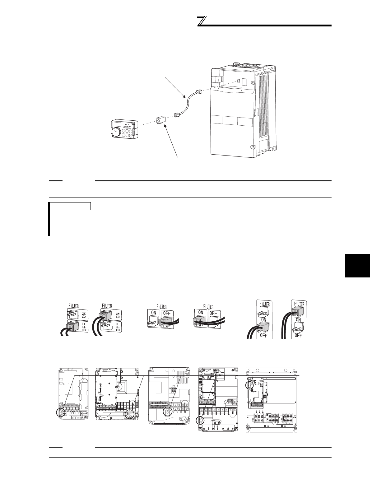
Wiring
2
INST ALLATION AND WIRING
Parameter unit connection cable
(FR-CB2)(option)
Operation panel(FR-DU07)
Operation panel connection connector
(FR-ADP)(option)
2.4.5 When connecting the operation panel using a connection cable
When connecting the operation panel (FR-DU07) to the inverter using a cable, the operation panel can be
mounted on the enclosure surface and operationality improves.
CAUTION
Do not connect the PU connector to the computer's LAN port, FAX modem socket or telephone connector.
The inverter and machi ne could be damaged due to differences in electrical sp ecif ic at ions.
REMARKS
⋅ Refer to page 4 for removal method of the oper at io n panel .
⋅ When using a commercially av ai l able connector and cable as a p ar ameter unit conn ect i on cable, refer t o the Instruction Manual
(applied).
⋅ The inverter can be connected to the computer and FR-PU04.
2.4.6 Connector with/without EMC filter
Change the connector from OFF to ON to make the EMC filter valid. (In the initial setting status, the connector is
fitted to OFF.)
(If it is difficult to disconnect the connector, use a pair of long-nose pliers, etc.)
FR-F720-00046 to 00250
FR-F740-00023 to 00126
EMC filter OFF EMC filter OFF EMC filter OFFEMC filter ON EMC filter ON EMC filter ON
(initial setting) (initial setting) (initial setting)
FR-F720-00105 to 00250
FR-F740-00023 to 00126
FR-F720-00340, 00490
FR-F740-00170, 00250
FR-F720-00340, 00490
FR-F740-00170, 00250
FR-F720-00630
FR-F740-00310, 00380
FR-F720-00770 to 01250
FR-F740-00470, 00620
FR-F720-00630 or more
FR-F740-00310 or more
FR-F720-01540 or more
FR-F740-00770 or more
Connector
with/without
EMC filter
The FR-F720-00046 and 00077 are not provided with the ON/OFF connector of the EMC filter.
CAUTION
For details of noise and leakage current, refer to the Instruction Manual (appl i ed).
VUW
23
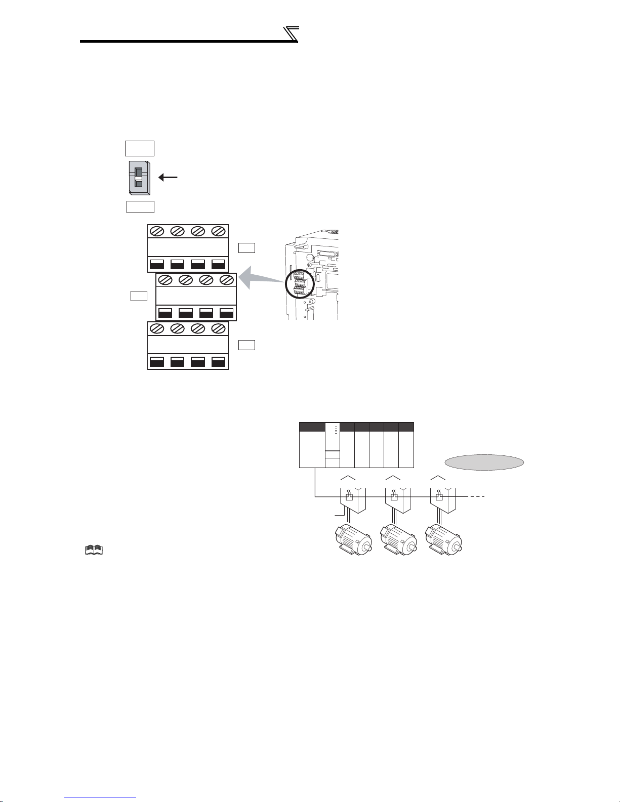
Wiring
2.4.7 RS-485 terminal block
⋅ Conforming standard: EIA-485(RS-485)
⋅ Transmission format: Multidrop link
⋅ Communication speed: MAX 38400bps
⋅ Overall length: 500m (1640.42feet)
⋅ Connection cable:Twisted pair cable
(4 paires)
OPEN
Terminating resistor switch
Factory-set to "OPEN".
Set only the terminating resistor switch of
100Ω
TXD
RDA1
(RXD1+)
the remotest inverter to the "100Ω" position.
RDB1
RDA2
RDB2
(RXD1-)
SDA1
(TXD1+)
(RXD2+)
SDB1
(TXD1-)
SDA2
(TXD2+)
(RXD2-)
SDB2
(TXD2-)
RXD
P5S
(VCC)SG(GND)
P5S
(VCC)SG(GND)
VCC
2.4.8 Communication operation
Using the PU connector or RS-485 terminal, you
can perform communication operation from a
personal computer etc. When the PU connector is
connected with a personal, FA or other computer
by a communication cable, a user program can run
and monitor the inverter or read and write to
parameters.
For the Mitsubishi inverter protocol (computer link
operation), communication can be performed with
the PU connector and RS-485 terminal.
For the Modbus RTU protocol, communication can
be performed with the RS-485 terminal.
For further details, refer to the instruction
manual (applied).
PLC
Multidrop link
Inverter Inverter Inverter
(32 inverters maximum
are connectable)
24
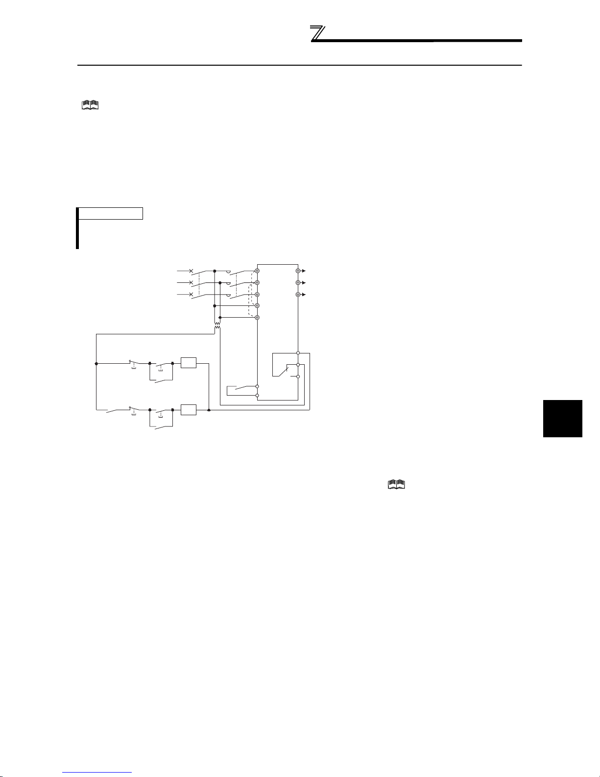
Power-off and magnetic contactor
2
INST ALLATION AND WIRING
Power
supply
MCCB
RA
U
V
A1
B1
C1
W
To the
motor
Inverter
MC
STF(STR)
T *1
R/L1
S/L2
T/L3
R1/L11
S1/L21
*2
OFF
ON
MC
Stop
Operation
RA
MC
Operation preparation
Start/Stop
RA
MC
SD
(MC)
2.5 Power-off and magnetic contactor (MC)
(1) Inverter input side magnetic contactor (MC)
On the inverter input side, it is recommended to provide an MC for the following purposes.
( Refer to page 3 for selection.))
1)To release the inverter from the power supply when the inverter's protective function is activated or when the drive
is not functioning (e.g. emergency stop operation).
2) To prevent any accident due to an automatic restart at restoration of power after an inverter stop made by a
power failure
3) The control power supply for inverter is always running and consumes a little power. When stopping the inverter
for an extended period of time, powering off the inverter will save power slightly.
4)To separate the inverter from the power supply to ensure safe maintenance and inspection work
The inverter's input side MC is used for the above purpose, select class JEM1038-AC3MC for the inverter input
side current when making an emergency stop during normal operation.
REMARKS
The MC may be switched on/off to start/stop the inverter. However, since repeated inrush currents at power on will shorten the
life of the converter circuit (switch ing life is about 1000,0 00 tim es), frequ ent starts and sto ps mus t be avoid ed. Turn on/off the
inverter start controlling terminals (STF, STR) to run/stop the inverter.
• Inverter start/stop circuit example
As shown on the left, always use the start
signal (ON or OFF across terminals STF or
STR-SD) to make a start or stop.
*1 When th e power supply is 400V c lass, install a
step-down transformer.
*2 Connect the power supply terminals R1/L11, S1/
L21 of the control circuit to the primary side of
the MC to hold an alarm signal when the
inverter's protective circuit is activated. At this
time, remove jumpers across terminals R/L1R1/L11 and S/L2-S1/L21. (Refer to page 19 for
removal of the jumper.)
(2) Handling of the inverter output side magnetic contactor
Switch the magnetic contactor between the inverter and motor only when both the inverter and motor are at a stop.
When the magnetic contactor is turned on while the inverter is operating, overcurrent protection of the inverter and
such will activate. When an MC is provided to switch to a commercial power supply, for example, it is recommended
to use commercial power supply-inverter switchover operation Pr. 135 to Pr. 139 ( Instruction Manual (applied)).
25
 Loading...