

Mitsubishi FR-F740-00126-EC, FR-F740-00023-EC, FR-F740-00170-EC, FR-F740-00250-EC, FR-F740-00310-EC Instruction Manual
...
INVERTER
INSTRUCTION MANUAL (Applied)
FR-F740-00023 to 02160-EC
WIRING
PRECAUTIONS FOR USE
OF THE INVERTER
PARAMETERS
PROTECTIVE FUNCTIONS
SPECIFICATIONS
1
2
3
4
5
Thank you for choosing this Mitsubishi Inverter.
This Instruction Manual (applied) provides instructions for advanced use of the FR-F700 series inverters.
Incorrect handling might cause an unexpected fault. Before using the inverter, always read this instruction manual and the instruction
manual (basic) [IB-0600176ENG] packed with the product carefully to use the equipment to its optimum.
This section is specifically about safety matters
Do not attempt to instal l, op era te, maintain or inspect the inver ter unt il you
have read through instruction manual (basic) and a ppended documents
carefully and can use the equipment correctly. Do not use the inverter until
you have a full knowledge of the equipment, safety information and
instructions. In this instruction manual, the safety instruction levels are
classified into "WARNING" and "CAUTION".
WARNING
CAUTION
Note that even the level may lead to a serious consequence
according to conditions. Please follow the instructions of both levels
because they are important to personnel safety.
1. Electric Shock Prev en tion
• While power is on or when the inverter is running, do not open the front cover.
Otherwise you may get an electric shock.
• Do not run the inverter with the front cover or wiring cover removed.
Otherwise, you may access the exposed high-voltage terminals or the
charging part of the circuitry and get an electric shock.
•
Even if power is o ff, do not remove the front cover except for wirin g or periodic
inspection.You may access the charged inverter circuits and get an electric shock.
• Before starting wiring or inspection, check to make sure that the operation
panel indicator is off, wait for at least 10 minutes after the power supply has
been switched off, and check that there are no residual voltage using a tester
or the like. The capacitor is charged with high voltage for some time after
power off and it is dangerous.
• This inverter must be earthed. Earthing must conform to the requirements of
national and local safety regulations and electrical codes. (JIS, NEC section
250, IEC 536 class 1 and other applicable standards)
• Any person who is involved in the wiring or inspection of this equipment
should be fully competent to do the work.
• Always install t he inverter before wiring. Otherwise, you may get an elect ric
shock or be injured.
• Perform setting dial and key operations with dry hands to prevent an electric
shock. Otherwise you may get an electric shock.
• Do not subject the cables to scratches, excessive stress, heavy loads or
pinching. Otherwise you may get an electric shock.
• Do not replace the cooling fan while power is on. It is dangerous to replace
the cooling fan while power is on.
•
Do not touch the printed circuit board with wet hands. You may get an electric shock.
2. Fire Prevention
• Mount the inverter to incombustible material. Mounting it to or near
combustible material can cause a fire.
• If the inverter has become faulty, switch off the inverter power.
A continuous flow of large current could cause a fire.
•
Do not connect a resistor directly to the DC terminals P/+, N/−. This could cause a fire.
3. Injury Prevention
• Apply only the voltage specified in the instruction manual to each terminal.
Otherwise, burst, damage, etc. may occur.
• Ensure that the cables are connected to the correct terminals. Otherwise,
burst, damage, etc. may occur.
• Always make sure that polarity is correct to prevent damage, etc. Otherwise,
burst, damage, etc. may occur.
• While power is on or for some time after power-off, do not touch the inverter
as it is hot and you may get burnt.
4. Additional Instruc tions
Also note the following points to prevent an accidental failure, injury, electric
shock, etc.
(1) Transporta tion and inst allation
• When carrying products, use correct lifting gear to prevent injury.
• Do not stack the inverter boxes higher than the number recommended.
• Ensure that installation position and material can withstand the weight of the
inverter. Install according to the information in the instruction manual.
• Do not install or operate the inverter if it is damaged or has parts missing.
• When carrying the inverter, do not hold it by the front cover or setting dial; it
may fall off or fail.
• Do not stand or rest heavy objects on the product.
• Check the inverter mounting orientation is correct.
• Prevent other conductive bodies such as screws and metal fragments or
other flammable substance such as oil from entering the inverter.
• As the inverter is a precision instrument, do not drop or subject it to impact.
• Use the inverter under the following environmental conditions. Otherwise, the
inverter may be damaged.
Ambient
temperature
Ambient humidity 90% RH or less (non-condensing)
Storage temperature -20°C to +65°C *
Atmosphere
Environment
Altitude, vibration
*Temperature applicable for a short time, e.g. in transit.
Assumes that incorrect handling may cause hazardous
conditions, resulting in death or sever e injury.
Assumes that incorrect handling may cause
hazardous conditions, resulting in medium or
slight injury, or may cause physical damage only.
CAUTION
WARNING
CAUTION
CAUTION
CAUTION
LD -10°C to +50°C (non-freezing)
SLD
(initial setting)
-10°C to +40°C (non-freezing)
Indoors (free from corrosive gas,
flammable gas, oil mist, dust and dirt)
Maximum 1000m above sea level for
standard operati on. Aft er tha t de rate by 3%
for every extra 500m up to 2500m (92%)
2
5.9m/s
or less (conforming to J I S C 0040)
(2) Wiring
• Do not install a power factor correction capacitor or surge suppressor on the
inverter output side.
• The connection orientation of the output cables U, V, W to the motor will affect
the direction of rotation of the motor.
CAUTION
(3) Test operation and adjustment
• Before starting operation, confirm and adjust the parameters. A failure to do
so may cause some machines to make unexpected motions.
(4) Operation
• When you have chosen the retry function, stay away from the equipment as it
will restart suddenly after an alarm stop.
• The key is valid only when the appropriate function setting has been
made. Prepare an emergency stop switch separately.
• Make sure that the start signal is off before resetting the inverter alarm. A
failure to do so may restart the motor suddenly.
• The load used should be a three-phase induction motor only. Connection of any
other electrical equipment to the inverter output may damage the equipment.
• Do not modify the equipment.
• Do not perform parts removal which is not instructed in this manual. Doing so
may lead to fault or damage of the inverter.
• The electronic thermal relay function does not guarantee protection of the
motor from overheating.
• Do not use a magnetic contactor on the inverter input for frequent starting/
stopping of the inverter.
• Use a noise filter to reduce the effect of electromagnetic interference.
Otherwise nearby electronic equipment may be affected.
• Take measures to suppress harmonics. Otherwise power supply harmonics
from the inverter may heat/damage the power factor correction capacitor and
generator.
• When a 400V class motor is inverter-driven, please use an insulationenhanced motor or measures taken to suppress surge voltages. Surge
voltages attributable to the wiring constants may occur at the motor terminals,
deteriorating the insulation of the motor.
• When parameter clear or all clear is performed, reset the required
parameters before starting operations. Each parameter returns to the initial
value.
• The inverter can be easily set for high-speed operation. Before changing its
setting, fully examine the performances of the motor and machine.
• In addition to the inverter's holding function, install a holding device to ensure
safety.
• Before running an inverter which had been stored for a long period, always
perform inspection and test operation.
• For prevention of damage due to static electricity, touch nearby metal before
touching this product to eliminate static electricity from your body.
(5) Emergency stop
• Provide a safety backup such as an emergency bra ke which will prevent the
machine and equipment from hazardous conditions if the inverter fails.
• When the breaker on the inverter input side trips, check for the wiring fault
(short circuit), damage to internal parts of the inverter, etc. Identify the cause
of the trip, then remove the cause and power on the breaker.
• When the protective function is activated, take the corresponding corrective
action, then reset the inverter, and resume operation.
CAUTION
WARNING
CAUTION
CAUTION
(6) Maintenance, inspection and parts replacement
CAUTION
• Do not carry out a megger (insulation resistance) test on the control circuit of
the inverter.
(7) Disposing of the inverter
CAUTION
• Treat as industrial waste.
General instructions
Many of the diagrams and drawings in this instruction manual show the
inverter without a cover, or partially open. Never run the inverter in this
status. Always replace the co ver and follow this instruction manual when
operating the inverter.
A-1

CONTENTS
1 WIRING 1
1.1 Inverter and peripheral devices..........................................................................2
1.1.1 Peripheral devices..................................................................................................................... 3
1.2 Wiring....................................................................................................................4
1.2.1 Terminal connection diagram ........................ ....... ...... ...... ....... ...... ....... ...... ............................... 4
1.3 Main circuit terminal specifications...................................................................5
1.3.1 Specification of main circuit terminal ......................................................................................... 5
1.3.2 Terminal arrangement of the main circuit terminal, power supply and the motor wiring. .......... 5
1.3.3 Cables and wiring length ........................................................................................................... 7
1.4 Control circuit specifications ...........................................................................10
1.4.1 Control circuit terminals........................................................................................................... 10
1.4.2 Control circuit terminal layout .................................................................................................. 12
1.4.3 Wiring instructions ................................................................................................................... 13
1.4.4 When connecting the control circuit and the main circuit separately
to the power supply (separate power)..................................................................................... 14
1.4.5 Changing the control logic....................................................................................................... 16
1.5 Connection of stand-alone option units................... ..... ..................................18
1.5.1 Connection of the brake unit (FR-BU)..................................................................................... 18
1.5.2 Connection of the brake unit (BU type) ................................................................................... 19
1.5.3 Connection of the high power factor converter (FR-HC) ......................................................... 19
1.5.4 Connection of the power regeneration common converter (FR-CV) ....................................... 20
1.5.5 Connection of the power factor improving DC reactor (FR-HEL) ............................................ 20
1.5.6 When connecting the operation panel using a connection cable ............................................ 21
2 PRECAUTIONS FOR USE OF THE INVERTER 23
2.1 Panel design.......................................................................................................24
2.1.1 Inverter installation environment.............................................................................................. 24
2.1.2 Cooling system types for inverter panel .................................................................................. 26
2.1.3 Inverter placement................................................................................................................... 27
2.2 Precautions for use of the inverter ..................................................................28
2.3 Others .................................................................................................................29
2.3.1 Leakage currents and countermeasures................................................................................. 29
2.3.2 Power-off and magnetic contactor (MC).................................................................................. 31
2.3.3 Installation of a reactor ............................................................................................................ 31
2.3.4 Inverter-generated noises and their reduction techniques ...................................................... 32
2.3.5 EMC filter................................................................................................................................. 34
I

2.3.6 Power supply harmonics ......................................................................................................... 35
2.3.7 Inverter-driven 400V class motor............................................................................................. 36
3 PARAMETERS 37
3.1 Parameter List........................ ..... .... ..... ..................................... ..... ..... ...............38
3.1.1 Parameter list .......................................................................................................................... 38
3.2 Adjust the output torque of the motor (current) ............................................ 53
3.2.1 Manual torque boost (Pr.0, Pr.46) .......................................................................................... 53
3.2.2 Simple magnetic flux vector control (Pr.80, Pr.90) ................................................................. 54
3.2.3 Slip compensation (Pr. 245 to Pr. 247) .... ...... ....... ...... ...... ....... ...... ....... ...... ............................ 55
3.2.4 Stall prevention operation
(Pr.22, Pr.23, Pr.48, Pr.49, Pr.66, Pr.148, Pr.149, Pr.154, Pr.156, Pr.157)........................... 56
3.2.5 Load pattern selection (Pr.14) ................................................................................................ 60
3.2.6 Multiple rating (Pr.570) .................................. ....... ...... ...... ....... ...... ....... ...... ....... ...... ............... 61
3.3 Limit the output frequency............................................................................... 62
Content
3.3.1 Maximum/minimum frequency (Pr. 1, Pr. 2, Pr. 18) ............................................................... 62
3.3.2 Avoid mechanical resonance points (Frequency jump) (Pr. 31 to Pr. 36) .............................. 63
3.4 Set V/F pattern................................................................................................... 64
3.4.1 Base frequency, voltage (Pr.3, Pr.19, Pr.47).......................................................................... 64
3.4.2 Adjustable 5 points V/F (Pr. 71, Pr. 100 to 109)..................................................................... 66
3.5 Frequency setting by external terminals........................................................ 67
3.5.1 Multi-speed setting operation (Pr. 4 to Pr. 6, Pr. 24 to Pr. 27, Pr. 232 to Pr. 239) ................. 67
3.5.2 Jog operation (Pr. 15, Pr. 16) ................................................................................................ 69
3.5.3 Input compensation of multi-speed and remote setting (Pr. 28)............................................. 71
3.5.4 Remote setting function (Pr. 59)............................................................................................. 72
3.6 Setting of acceleration/deceleration time and
acceleration/deceleration pat ter n.......................... .... ...................................... 74
3.6.1 Setting of the acceleration and deceleration time (Pr.7, Pr.8, Pr.20, Pr.21, Pr.44, Pr.45)...... 74
3.6.2 Starting frequency and start-time hold function (Pr.13, Pr.571) ............................................. 76
3.6.3 Acceleration/deceleration pattern (Pr.29, Pr.140 to Pr.143).............................. ...... ....... ...... .. 77
3.7 Selection and protection of a motor ............................................................... 78
3.7.1 Motor protection from overheat (Electronic thermal relay function) (Pr.9).............................. 78
3.7.2 Applied motor (Pr.71) ............................................................................................................. 80
3.8 Motor brake and stop operation...................................................................... 81
3.8.1 DC injection brake (Pr. 10 to Pr. 12)....................................................................................... 81
3.8.2 Selection of a regenerative brake (Pr. 30, Pr.70) ................................................................... 83
3.8.3 Stop selection (Pr.250)........................................................................................................... 84
II

3.9 Function assignment of external terminal and control................................. 85
3.9.1 Input terminal function selection (Pr.178 to Pr.189) ............................................................... 85
3.9.2 Inverter output shutoff signal (MRS signal, Pr. 17)................................................................. 87
3.9.3 Second function RT signal reflection time selection (Terminal RT, Pr. 155) .......................... 88
3.9.4 Start signal selection (Terminal STF, STR, STOP, Pr. 250)................................................... 89
3.9.5 Output terminal function selection (Pr. 190 to Pr. 196)........................................................... 91
3.9.6 Detection of output frequency (SU, FU, FU2 signal, Pr. 41 to Pr. 43, Pr. 50) ........................ 95
3.9.7 Output current detection function
(Y12 signal, Y13 signal, Pr. 150 to Pr. 153, Pr. 166, Pr. 167) ................................................ 96
3.9.8 Remote output function (REM signal, Pr. 495 to Pr. 497) ...................................................... 98
3.10 Monitor display and monitor output signal.................................................... 99
3.10.1 Speed display and speed setting (Pr.37, Pr.144)................................................................... 99
3.10.2 DU/PU monitor display selection (Pr.52, Pr.170, Pr.171, Pr.268, Pr.563, Pr.564, Pr.891) .. 100
3.10.3 CA, AM terminal function selection (Pr.54 to Pr.56, Pr.158, Pr.867, Pr.869) ....................... 104
3.10.4 Terminal CA, AM calibration (Calibration parameter C0 (Pr. 900), C1 (Pr. 901), C8 (pr.930) to
C11 (Pr. 931))....................................................................................................................... 106
3.11 Operation selection at power failure and instantaneous power failure..... 109
3.11.1 Automatic restart after instantaneous power failure
(Pr. 57, Pr. 58, Pr. 162 to Pr. 165, Pr. 611) .......................................................................... 109
3.11.2 Power failure-time deceleration-to-stop function (Pr. 261 to Pr. 266)................................... 112
3.12 Operation setting at alarm occurrence......................................................... 114
3.12.1 Retry function (Pr. 65, Pr. 67 to Pr.69)................................................................................. 114
3.12.2 Alarm code output selection (Pr.76) ..................................................................................... 116
3.12.3 Input/output phase failure protection selection (Pr.251, Pr.872) .......................................... 117
3.13 Energy saving operation and energy saving monitor................................. 118
3.13.1 Energy saving control and optimu m excita tio n contro l (Pr.6 0) ............. ...... ....... ...... ....... ...... 118
3.13.2 Energy saving monitor (Pr. 891 to Pr. 899) .......................................................................... 119
3.14 Motor noise, noise reduction......................................................................... 124
3.14.1 PWM carrier frequency and Soft-PWM control (Pr.72, Pr.240, Pr.260) ............................... 124
3.15 Frequency setting by analog input (terminal 1, 2, 4)................................... 125
3.15.1 Analog input selection (Pr.73, Pr.267).................................................................................. 125
3.15.2 Analog input compensation (Pr.73, Pr.242, Pr.243, Pr.252, Pr.253).................................... 127
3.15.3 Input filter time constant (Pr.74) ........................................................................................... 128
3.15.4 Bias and gain of frequency setting voltage (current)
(Pr. 125, Pr. 126, Pr. 241, C2(Pr. 902) to C7(Pr. 905)) ........................................................ 129
3.15.5 4mA input check of current input (Pr. 573)........................................................................... 134
3.16 Misoperation prevention and parameter setting restriction....................... 136
3.16.1 Reset selection/disconnected PU detection/PU stop selection (Pr.75) ................................ 136
III

3.16.2 Parameter write disable selection (Pr.77)............................................................................. 139
3.16.3 Reverse rotation prevention selection (Pr.78) ...................................................................... 140
3.16.4 Display of applied parameters and user group function (Pr.160, Pr.172 to Pr.174) ............. 140
3.17 Selection of operation mode and operation location.................................. 142
3.17.1 Operation mode selection (Pr. 79)........................................................................................ 142
3.17.2 Operation mode at power on (Pr. 79, Pr. 340) ..................................................................... 150
3.17.3 Operation command source and speed command source during
communication operation (Pr. 338, Pr. 339, Pr. 550, Pr. 551).............................................. 151
3.18 Communication operation and setting......................................................... 156
3.18.1 Wiring and configuration of PU connector............................................................................ 156
3.18.2 Wiring and arrangement of RS-485 terminals ...................................................................... 158
3.18.3 Initial settings and specifications of RS-485 communication
(Pr. 117 to Pr. 124, Pr. 331 to Pr. 337, Pr. 341) ................................................................... 161
3.18.4 Communication EEPROM write selection (Pr. 342) ............................................................. 162
3.18.5 Mitsubishi inverter protocol (computer link communication)................................................. 163
3.18.6 Modbus-RTU communication specifications (Pr. 331, Pr. 332, Pr. 334, Pr. 343, Pr. 549) ... 173
3.19 Special operation and frequency setting...................................................... 184
3.19.1 PID control (Pr. 127 to Pr. 134, Pr. 575 to Pr. 577).............................................................. 184
3.19.2 Commercial power supply-inverter switchover function (Pr. 135 to Pr. 139, Pr. 159) .......... 192
3.19.3 Advanced PID function (pump function) (Pr. 575 to Pr. 591) ............................................... 197
3.19.4 Traverse function (Pr. 592 to Pr. 597) .................................................................................. 206
3.19.5 Regeneration avoidance function (Pr.882 to Pr.886) ........................................................... 208
Content
3.20 Useful functions.............................................................................................. 210
3.20.1 Cooling fan operation selection (Pr.244) .............................................................................. 210
3.20.2 Display of the life of the inverter parts (Pr. 255 to Pr .259)................................................... 211
3.20.3 Maintenance timer alarm (Pr.503, Pr.504) ........................................................................... 213
3.20.4 Current average value monitor signal (Pr.555 to Pr.557) ..................................................... 214
3.20.5 Free parameter (Pr.888, Pr.889) .......................................................................................... 216
3.21 Setting from the parameter unit, operation panel........................................ 217
3.21.1 PU display language selection (Pr.145) ............................................................................... 217
3.21.2 Operation panel frequency setting/key lock operation selection (Pr. 161) ........................... 217
3.21.3 Buzzer control (Pr. 990)........................................................................................................ 219
3.21.4 PU contrast adjustment (Pr.991) .......................................................................................... 219
3.22 Parameter clear........................... .... ...................................... .... ..... ................. 220
3.23 All parameter clear.................................... .... ...................................... .... ..... ... 221
3.24 Parameter copy............................... ..... ..... ..................................... ..... .... ..... ... 222
3.25 Parameter verification............................................ .... .................................... 223
IV

3.26 Check and clear of the alarm history.............................................................224
4 PROTECTIVE FUNCTIONS 227
4.1 List of alarm display............................................................. .... ..... ..................228
4.2 Causes and corrective actions.......................................................................229
4.3 Reset method of protective function .............................................................240
4.4 Correspondences between digital and actual characters ...........................240
4.5 Meters and measuring methods.....................................................................241
4.5.1 Measurement of powers........................................................................................................ 241
4.5.2 Measurement of voltages and use of PT............................................................................... 242
4.5.3 Measurement of currents....................................................................................................... 242
4.5.4 Use of CT and transducer ..................................................................................................... 243
4.5.5 Measurement of inverter input power factor .......................................................................... 243
4.5.6 Measurement of converter output voltage (across terminals P/+ - N/-)................................. 243
4.6 Check first when you have troubles. .............................................................244
4.6.1 Motor does not rotate as commanded................................................................................... 244
4.6.2 Motor generates abnormal noise........................................................................................... 244
4.6.3 Motor generates heat abnormally.......................................................................................... 244
4.6.4 Motor rotates in opposite direction ........................................................................................245
4.6.5 Speed greatly differs from the setting.................................................................................... 245
4.6.6 Acceleration/deceleration is not smooth................................................................................ 245
4.6.7 Motor current is large............................................................................................................. 245
4.6.8 Speed does not increase....................................................................................................... 245
4.6.9 Speed varies during operation............................................................................................... 245
4.6.10 Operation panel (FR-DU07) display is not operating............................................................. 245
4.6.11 Parameter write cannot be performed................................................................................... 245
5 SPECIFICATIONS 247
5.1 Rating................................................................................................................248
5.2 Common specifications ..................................................................................249
5.3 Outline dimension drawings...........................................................................251
5.3.1 Inverter outline dimension drawings...................................................................................... 251
5.3.2 Operation panel (FR-DU07) outline dimension drawings...................................................... 254
5.3.3 Parameter unit (FR-PU04) outline dimension drawings ........................................................ 254
V

1 WIRING
This chapter describes the basic "WIRING" for use of this
product.
Always read the instructions before using the equipment
1.1 Inverter and perip her a l dev ic es................ .. .............2
1.2 Wiring......................................................................4
1.3 Main circuit terminal specifications..........................5
1.4 Control circuit specifications....................................10
1.5 Connection of stand-alone option units...................18
<Abbreviations>
DU ..........................................Operation panel (FR-DU07)
PU..................... ..... ..... ...... ..... ..... .Operation panel (FR-DU07 ) a nd p aram eter unit (FR-PU04 )
Inverter ...................................Mitsubishi inverter FR-F700 series
FR-F700 .................................Mitsubishi inverter FR-F700 series
Pr............................................Parameter Number
PU operation...........................Operation using the PU (FR-DU07/FR-PU04).
External operation ..................Operation using the control circuit signals
Combined operation ............... Combined operation using the PU (FR-DU07/FR-PU04)
and external operation.
Mitsubishi standard motor ......SF-JR
Mitsubishi constant-torque motor
<Trademarks>
•L
ONWORKS is a registered trademark of Echelon Corporation in the U.S.A
• CC-Link is a registered trademark of CC-Link Partner Association.
• Other company and product names herein are the trademarks and registered
trademarks of their respective owners.
.SF-HRCA
1
2
3
4
5
1
Inverter and peripheral devices
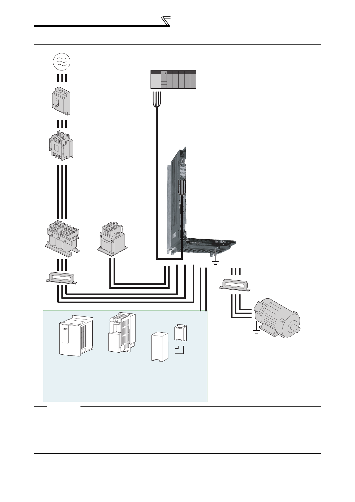
1.1 Inverter and peripheral devices
3-phase AC power supply
Use within the permissible power supply
specifications of the inverter.
(Refer to page 248)
Moulded case circuit
breaker (MCCB)
or earth leakage circuit
breaker (ELB), fuse
The breaker must be selected carefully since
an in-rush current flows in the inverter at
power on.
(Refer to page 3)
Magnetic contactor(MC)
Install the magnetic contactor to ensure safety.
Do not use this magnetic contactor to start and
stop the inverter.
Doing so will cause the inverter life to be shorten.
(Refer to page 3)
Reactor (FR-HAL, FR-HEL)
Reactors (option) should be used when power
harmonics measures are taken, the power factor
is to be improved or the inverter is installed near a
large power supply system (1000kVA or more).
The inverter may be damaged if you do not use
reactors.
Select the reactor according to the model.
Remove the jumpers across terminals P/+-P1 to
connect to the DC reactor.
(Refer to page 3.)
PLC
RS-485 terminal block
The inverter can be
connected with computers
such as PLC.
It supports Mitsubishi inverter
protocol and Modbus-RTU
(binary) protocol.
Inverter
(FR-F700)
The life of the inverter is influenced by ambient
temperature. The ambient temperature should be as low
as possible within the permiss ible range . Especi ally w hen
mounting the inverter inside an enclosure, take cautions
of the ambient temperature. (Refer to page 27)
Wrong wiring might lead to damage o f the inverter. The
control signal lines must be kept fully away from the main
circuit to protect them from noise.(Refer to page 4)
Refer to page 34 for the built-in EMC filter.
Noise filter
AC reactor
(FR-HAL)
Noise filter
(FR-BLF)
It is not necessary
for the 01160 or less.
DC reactor
(FR-HEL)
For the 01800 or more, a
DC reactor is supplied.
Always install the reactor.
P/+
P1
R/L1 S/L2 T/L3
N/-P/+
Earth
UVW
(FR-BSF01, FR-BLF)
Install a noise filter to reduce
the electromagnetic noise
generated from the inverter.
Effective in the range from
about 1MHz to 10MHz.
When more wires are passed
through, a more effective result
can be obtained.
Motor
Brake unit
*1
(FR-BU
, MT-BU5*2)
Earth
Devices connected to the output
Do not install a power factor correction capacitor,
varistor, arrester or radio noise filter on the output
side of the inverter.
When installing a moulded case circuit breaker on the
output side of the inverter, contact each manufacturer
for selection of the moulded case circuit breaker.
Earth
To prevent an electric shock, always earth the
motor and inverter.
High power factor
converter
*2
(FR-HC, MT-HC
Power supply harmonics
can be greatly suppressed.
Install this as required.
)
*1 Compatible with the 01160 or less.
*2 Compatible with the 01800 or more.
Power regeneration
common converter
*1
)
(FR-CV
Power regeneration
converter (MT-RC
Greater braking capability
is obtained.
Install this as required.
*2
P/+
PR
Resistor unit
*1
(FR-BR
The regenerative braking
)
capability of the inverter can be
exhibited fully.
Install this as required.
, MT-BR5*2)
PR
P/+
CAUTION
· Do not in st all a p ower fa ctor corr ecti on cap acitor o r surge supp ressor on the inve rter output s ide. This will c ause the in verter
to trip or power factor corr ec t io n capacitor, varistor and arrester to be damaged. If any of the above devices are conne ct ed,
immediately remove them.
· Electromagnetic wave interference
The input/out put (main ci rcuit) of t he invert er include s high freq uency compone nts, which may interfere w ith the co mmunicatio n
devices (such as AM radios) used near the inverter. An EMC filter can minimize noise interference.
(Refer to
· Refer to the instruction manual of each opti on a nd peripheral devices for details of pe ripheral devices.
page 34
.)
2
Inverter and peripheral devices
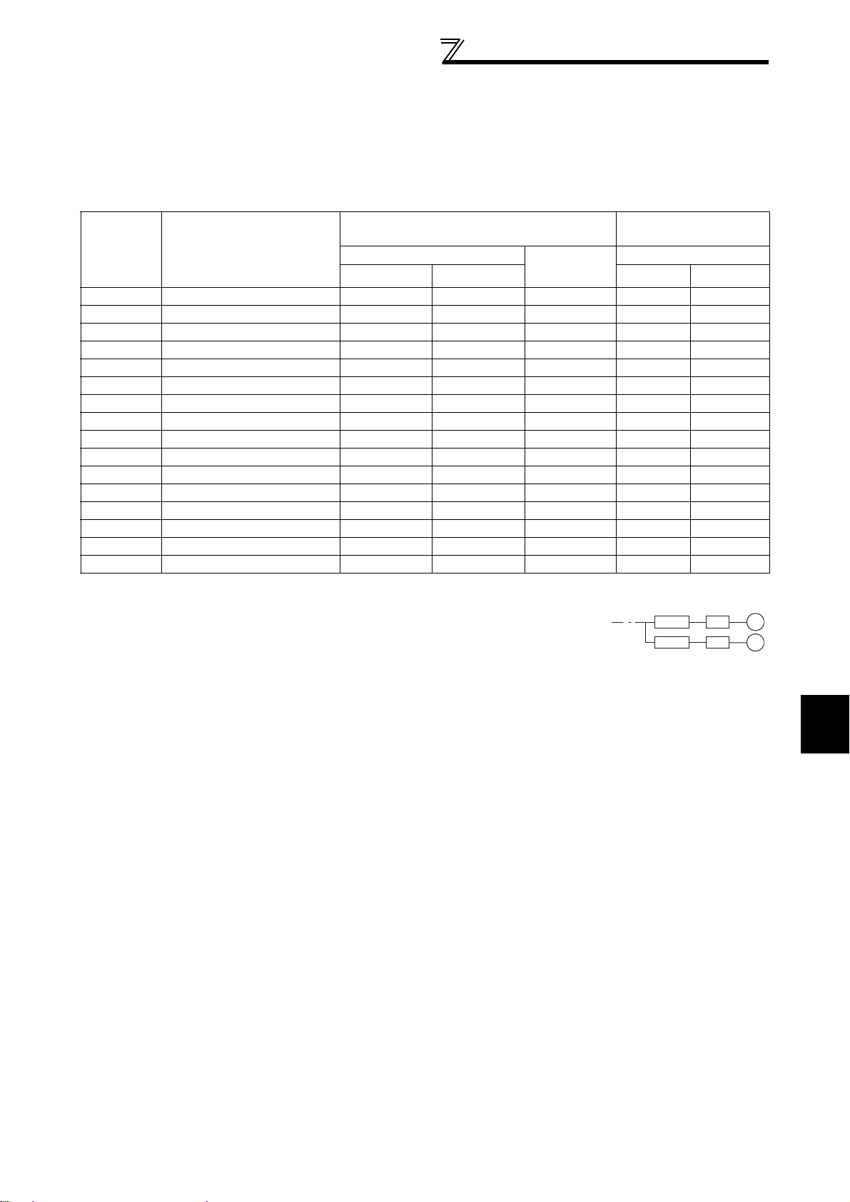
1.1.1 Peripheral devices
Check the motor capacity of the inverter you purchased. Appropriate peripheral devices must be selected according to the
capacity. Refer to the following list and prepare appropriate peripheral devices:
400V class
Input Side Magnetic
Contactor
*3
Reactor connection
without
with
Motor
Output (kW)
*1
Applicable Inverter Type
Breaker Selection
Reactor connection
without with
*2
with commercial
power-supply
operation
0.75 FR-F740-00023-EC 30AF 5A 30AF 5A 30AF 5A S-N10 S-N10
1.5 FR-F740-00038-EC 30AF 10A 30AF 10A 30 AF 10A S-N10 S-N10
2.2 FR-F740-00052-EC 30AF 10A 30AF 10A 30 AF 15A S-N10 S-N10
3.7 FR-F740-00083-EC 30AF 20A 30AF 15A 30 AF 20A S-N10 S-N10
5.5 FR-F740-00126-EC 30AF 30A 30AF 20A 30 AF 30A S-N20 S-N11, N12
7.5 FR-F740-00170-EC 30AF 30A 30AF 30A 30 AF 30A S-N20 S-N20
11 FR-F740-00250-EC 50AF 50A 50AF 40A 50A F 50 A S-N20 S-N20
15 FR-F740-00310-EC 100AF 60A 50AF 50A 100AF 60A S-N25 S-N20
18.5 FR-F740-00380-EC 100AF 75A 100AF 60A 100AF 75A S-N25 S-N25
22 FR-F740-00470-EC 100AF 100A 100AF 75A 100AF 100A S-N35 S-N25
30 FR-F740-00620-EC 225AF 125A 225AF 100A 225AF 125A S-N50 S-N50
37 FR-F740-00770-EC 225AF 150A 225AF 125A 225AF 150A S-N65 S-N50
45 FR-F740-00930-EC 225AF 175A 225AF 150A 225AF 175A S-N80 S-N65
55 FR-F740-01 160-EC 225AF 200A 225AF 175A 225AF 200A S-N80 S-N80
75 FR-F740-01800-EC 225AF 225A 400AF 300 A
90 FR-F740-02160-EC 225AF 225A 400AF 350 A
*1 Selections for use of the Mitsubishi 4-pole standar d motor with power supply voltage of 400VAC 50Hz.
*2 Select the MCCB according to the inverter power supply capacity.
Install one MCCB per inverter.
For installations in the United States or Canada, use the fuse certified by the UL and cUL.
(Refer to the Instruction Ma nual (bas ic s) .)
*3 The electrical durability of magnetic contactor is 500,000 times. When the magnetic contactor is used for emergency stop during motor
driving, the electrical durability is 25 times.
When using the MC for emerge ncy stop d urin g motor d riving or usin g on the motor si de dur ing c ommerc ial-power s upply op eration , select the
MC with class AC-3 rated current for the motor rated current.
*4 When the breaker on the inverter primary side trips, check for the wiring fault (short circuit), damage to internal parts of the inverter, etc.
Identify the cause of the trip, then remove the cause and power on the breaker.
S-N150
S-N180
MCCB INV
MCCB INV
IM
IM
1
WIRING
3
Wiring
1.2 Wiring
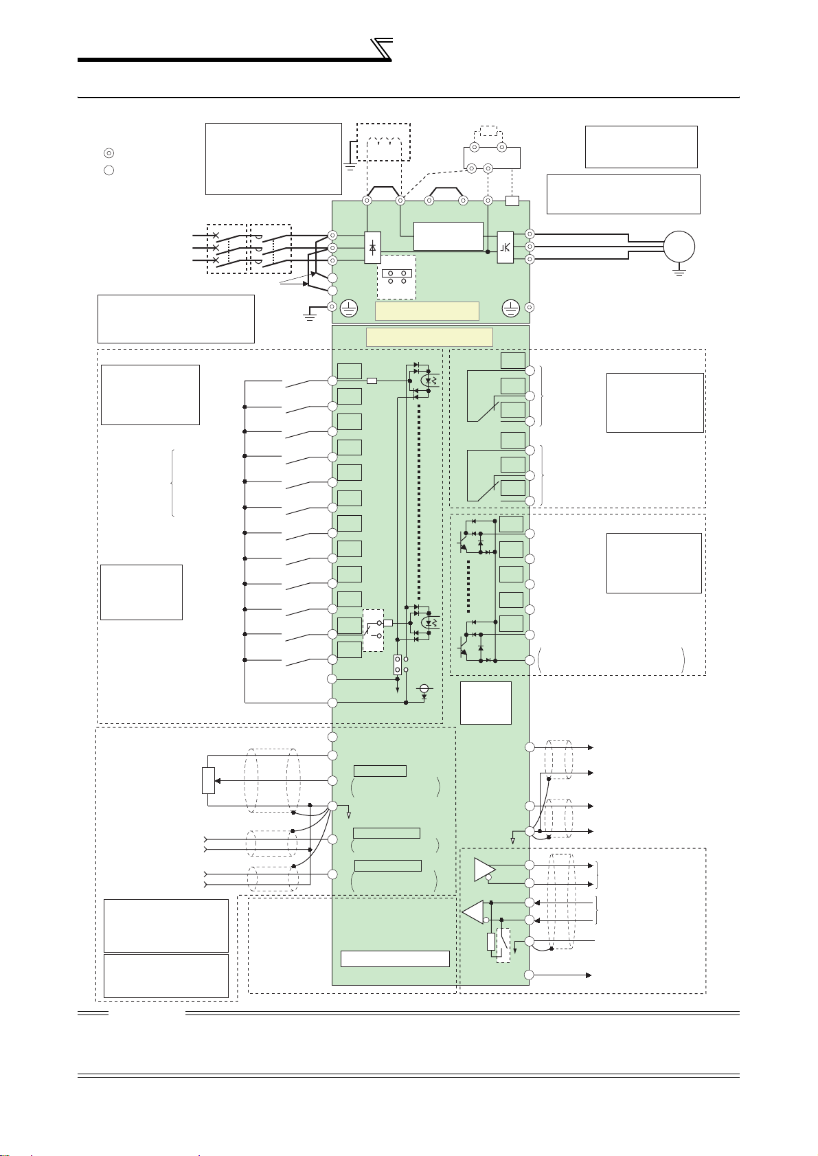
1.2.1 Terminal connection diagram
N/-
RUN
TXD+
TXD-
RXD+
RXD-
resistor
VCC
Brake resistor
(Option)
*6. The CN8 connector
Brake unit
(Option)
*7.
Please do not remove or use
terminals PR and PX or the
CN8
*6
jumper connected.
U
V
W
C1
B1
Relay output 1
(Alarm output)
A1
C2
B2
Relay output 2
A2
Running
SU
Up to frequency
IPF
Instantaneous
power failure
OL
Overload
FU
Frequency detection
SE
Open collector output common
Sink
/source common
CA
AM
5
SG
is provided with the
01800 or more.
Motor
IM
Relay output
Terminal functions
vary with the output
terminal assignment
(Pr. 195, Pr. 196)
Open collector output
Terminal functions
vary with the output
terminal assignment
(Pr. 190 to Pr. 194)
(+)
Analog current output
(0 to 20mADC)
(-)
(+)
Analog signal output
(0 to 10VDC)
(-)
RS-485 terminal
Data transmission
Data reception
GND
(Permissible load
5V
current 100mA)
Source logic
*1. DC reactor (FR-HEL)
Main circuit terminal
Control circuit terminal
3-phase AC
power supply
*2. To supply power to the
control circuit separately,
The DC reactor supplied with the
01800 or more should be
connected to these terminals.
When a DC reactor is connected,
remove the jumper across P1-P/+
for the 01160 or less.
Jumper
MC
*2
MCCB
Earth
Earth
R/L1
S/L2
T/L3
R1/L11
S1/L21
*1
Jumper
P1
P/+
Jumper
PR*7
Inrush current
limit circuit
ON
Connector for
with/without
OFF
EMC filter
Main circuit
PX*7
remove the jumper across
R1/L11 and S1/L21.
Control circuit
Control input signals (No voltage input allowed)
Terminal functions
vary with the input
terminal assignment
(Pr. 178 to Pr. 189)
Forward
rotation
start
Reverse
rotation
start
Start self-holding selection
High speed
Multi-speed
selection
Middle speed
Low speed
Jog mode
Second function selection
*3. AU terminal
can be used
Output stop
as PTC input
terminal.
Terminal 4 input selection
(Current input selection)
Selection of automatic restart
Contact input common (Sink)
(Common for external power supply transistor)
(Common for external power supply transistor)
after instantaneous
24VDC power supply
Contact input common
Reset
power failure
Frequency setting signal (Analog)
Ω
(+)
(-)
(+)
(-)
3
2
1
Connector
for plug-in option
connection
Frequency setting
potentiometer
1/2W1k
*5
Auxiliary input
Terminal 4 input
(Current input)
*
4. Terminal input
specifications can be
changed by analog input
specifications switchover
(Pr. 73, Pr. 267).
*
5. It is recommended to use
2W1kΩ when the
frequency setting signal is
changed frequently.
STF
STR
STOP
RH
RM
RL
JOG
RT
MRS
RES
*3
AU
AU
PTC
CS
SD
SOURCE
PC
10E(+10V)
10(+5V)
0 to 5VDC
2
0 to 10VDC
4 to 20mADC
5
(Analog common)
0 to ±10VDC
1
0 to ±5VDC
4 to 20mADC
4
0 to 5VDC
0 to 10VDC
Option connector 1
SINK
24V
selected
selected
selected
*
4
*
4
*
4
Terminating
PU
connector
CAUTION
· To prevent a malfunction due to noi se, keep the signal cables more th an 10cm away from the powe r ca bles.
· After wiring, wire offcuts must not be left in the inverter.
Wire offcuts can cause an alarm , fai l ur e or ma lfunction. Always keep the inv er te r c le an.
When drilling mounting holes in a control box etc., take care not to allow chips and other foreign matter to enter the inverter.
Earth
4
1.3 Main circuit terminal specifications
r
1.3.1 Specification of main circuit terminal
Main circuit terminal specifications
Terminal
Symbol
R/L1,
S/L2,
T/L3
Terminal Name Description
Connect to the commercial power supply.
AC power input
Keep these termina ls open when u sing the high power factor converter
(FR-HC, MT - HC) or power rege nera tion commo n converte r (FR-C V).
U, V, W Inverter output Connect a three-phase squirrel-cage motor.
Connected to the AC power supply terminals R/L1 and S/L2. To retain
the alarm display and alarm output or when using the high power factor
converter (FR-HC, MT-HC) or power regeneration common converter
(FR-CV), remove the jumpers from terminals R/L1-R1/L11 and S/L2-
R1/L11,
S1/L21
Power supply for
control circuit
S1/L21 and apply external power to these terminals.
Do not turn off the power supply for control circuit (R1/L1 1, S1/L21) with
the main circuit power (R/L1, S/L2, T/L3) on. Doing so may damage the
inverter. The circuit should be configured so that the main circuit power
(R/L1, S/L2, T/L3) is also turned off when the power supply for control
circuit (R1/L11, S1/L21) is off.
00380 or less : 60VA, 00470 to 02160 : 80VA
Connect the br ake un it (FR- B U, BU and MT-BU5), po we r
P/+, N/-
Brake unit
connection
regeneration common converter (FR-CV), high power factor
converter ( FR-H C and MT-HC) or pow er r e ge ne rat i on conv er ter (MTRC).
For the 01160 or less, remove the jumper across terminals P/+ - P1
and connect the DC reactor. (For the 01800 or more, a DC reactor
is standard-equipped.)
P/+, P1
DC reactor
connection
PR, PX Please do not remove or use terminals PR and PX or the jumper connected.
Earth For earthing the inverter chassis. Must be earthed.
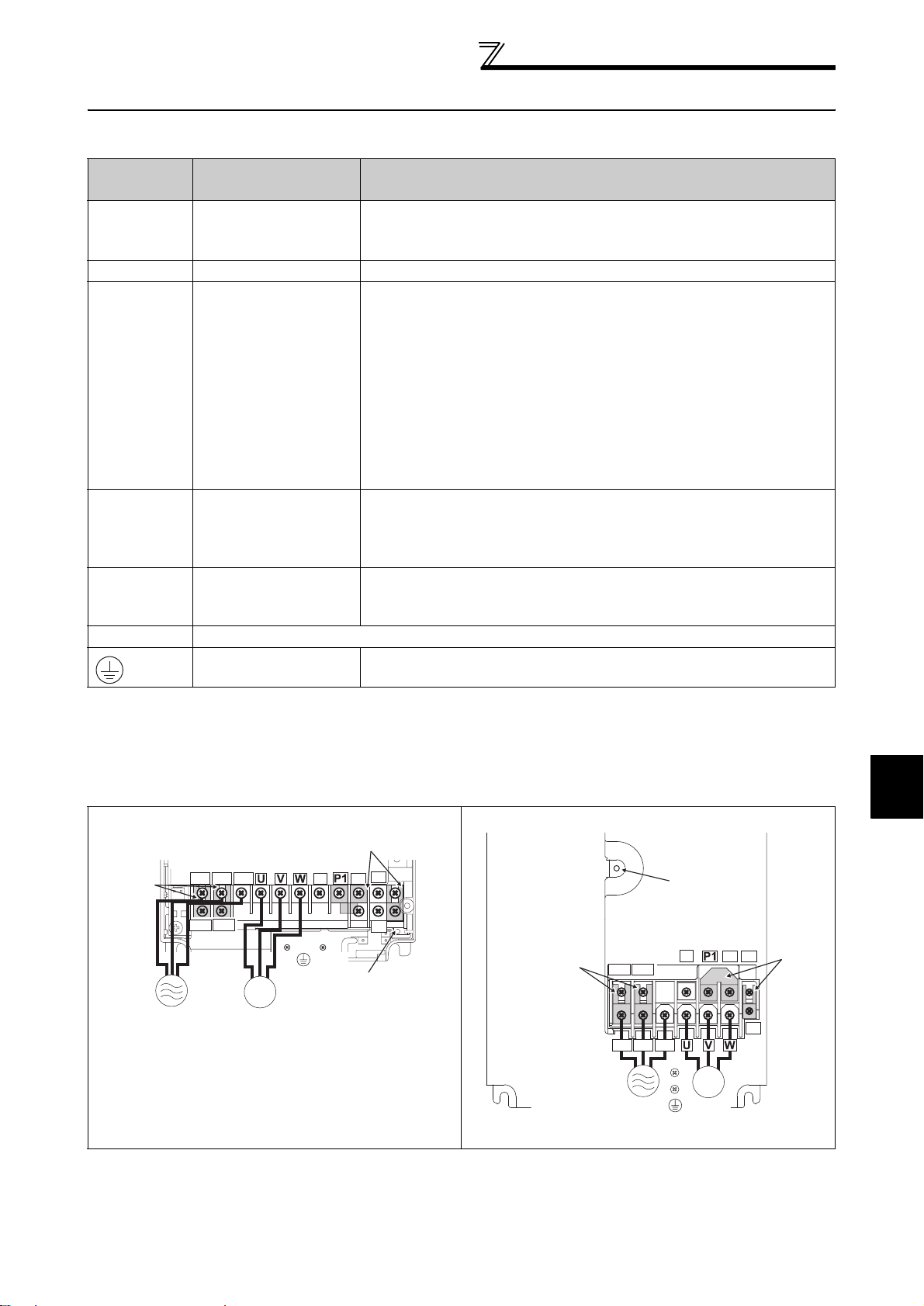
1.3.2 Terminal arrangement of the main circuit terminal, power supply and the motor wiring.
400V class
FR-F740-00023 to 00126-EC FR-F740-00170, 00250-EC
Jumper
Power supply
Screw size (M4)
R/L1 S/L2 T/L3
R1/L11 S1/L21
IM
Motor
Screw size
(M4)
N/-
Jumper
PR
P/+
PX
Charge lamp
Jumper
Screw size
(M4)
R1/L11 S1/L21
R/L1 S/L2 T/L3
Charge lamp
N/-
P/+
PR
Jumpe
PX
IM
Power supply
Motor
Screw size
(M4)
1
WIRING
5
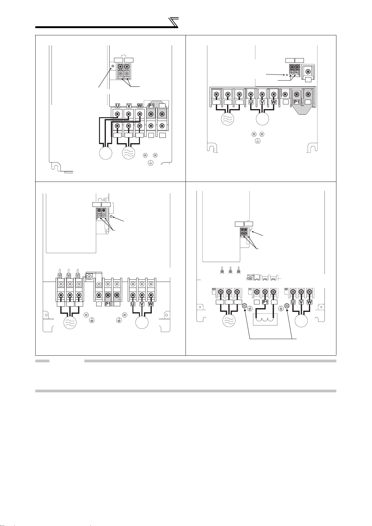
Main circuit terminal specifications
IM
R/L1 S/L2 T/L3
N/-
P/+
R1/L11 S1/L21
DC reactor
Screw size (M10)
FR-F740-00310, 00380-EC FR-F740-00470, 00620-EC
R1/L11 S1/L21
Charge lamp
Screw size (M5)
Screw size
(M4)
R/L1 S/L2 T/L3
Jumper
Jumper
N/-
P/+
PR
Screw size (M6)
R/L1 S/L2 T/L3
Power supply
Charge lamp
Screw size (M6)
IM
Motor
Power supply
Screw size (M5)
FR-F740-00770 to 01160-EC FR-F740-01800 to 02160 - EC
R1/L11 S1/L21
Screw size(M4)
Charge lamp
Jumper
Screw size (M4)
Screw size (M4)
Jumper
IM
Motor
Charge lamp
R1/L11 S1/L21
N/-
Jumper
PR
P/+
Jumper
Screw size
(00770A: M6
R/L1 S/L2 T/L3
Power
supply
00930A, 01160A: M8)
N/-
P/+
Jumper
Screw size
(00770A: M6
00930A, 01160A: M8)
IM
Motor
Screw size
(01800: M8, 02160: M10)
Power
supply
Screw size
(01800: M8, 02160: M10)
Motor
Screw size
(01800: M8,
02160: M10)
CAUTION
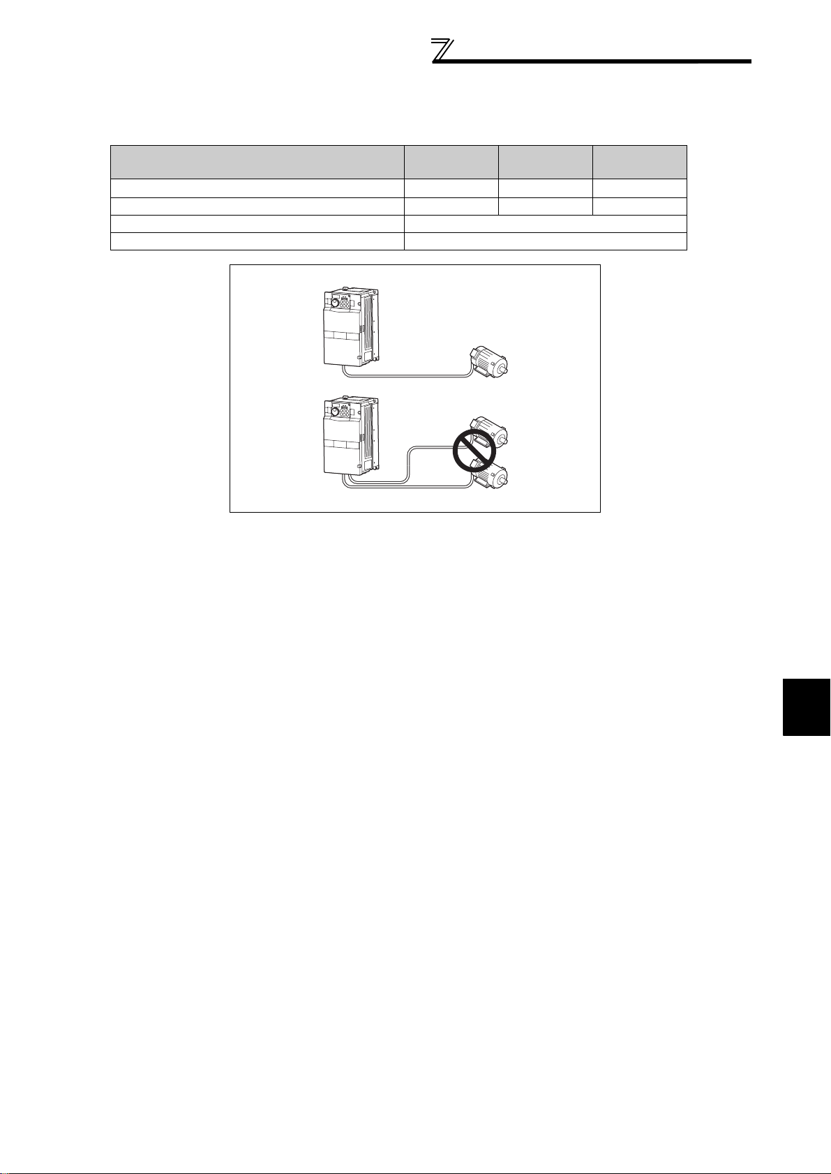
· The power supply cables must be connec ted to R/L1, S/L2, T/L3. Never conn ect the power cable to the U, V, W of the
inverter. Doing so will damage the inverter. (Phase sequence needs not to be matched.)
· Connect the motor to U, V, W. At this time, turning on the forward rotation switch (signal) rotates the motor in the
counterclockwise direction when viewed from the motor shaft.
6

Main circuit terminal specifications
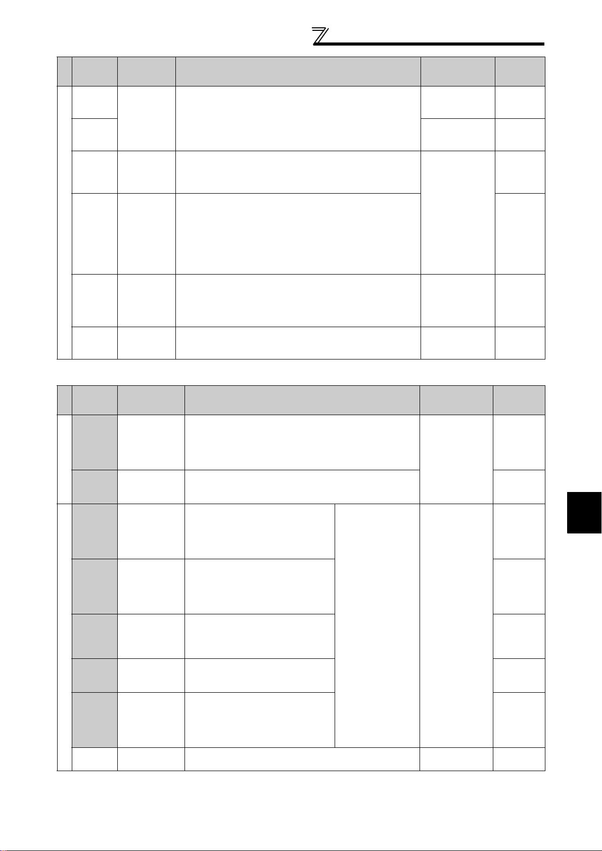
1.3.3 Cables and wiring length
(1) Applied cable size
Select the recommended cable size to ensure that a voltage drop will be 2% max.
If the wiring distance is long between the inverter and motor, a main circuit cable voltage drop will cause the motor
torque to decrease especially at the output of a low frequency.
The following table indicates a selection example for the wiring length of 20m.
400V class (when input power supply is 440V based on the rated current for 110% overload for 1 minute)
Applicable
Inverter Type
FR-F740-00023 to
00083-EC
FR-F740-00126-EC M4 1.5 2-4 2-4 2 2 3.5 12 14 2.5 2.5 4
FR-F740-00170-EC M4 1.5 5.5-4 5.5-4 3.5 3.5 3.5 12 12 4 4 4
FR-F740-00250-EC M4 1.5 5.5-4 5.5-4 5.5 5.5 8 10 10 6 6 10
FR-F740-00310-EC M5 2.5 8-5 8-5 8 8 8 8 8 10 10 10
FR-F740-00380-EC M5 2.5 14-5 8-5 14 8 14 6 8 16 10 16
FR-F740-00470-EC M6 4.4 22-6 14-6 22 14 14 4 6 25 16 16
FR-F740-00620-EC M6 4.4 22-6 22-6 22 22 14 4 4 25 25 16
FR-F740-00770-EC M6 4.4 22-6 22-6 22 22 14 4 4 25 25 16
FR-F740-00930-EC M8 7.8 38-8 38-8 38 38 22 1 2 50 50 25
FR-F740-01160-EC M8 7.8 60-8 60-8 60 60 22 1/0 1/0 50 50 25
FR-F740-01800-EC M8 7.8 60-10 60-10 60 60 38 1/0 1/0 50 50 25
FR-F740-02160-EC M10 14.7 100-10 100-10 100 100 38 3/0 3/0 70 70 35
*1 For the 01160 or less, the recommended cable size is that of the HIV cable (600V class 2 vinyl-insulated cable) with continuous maximum permissible
temperature of 75°C. Assumes that the ambient temperature is 50°C or less and the wiring distance is 20m or less.
For the 01800 or more, the recommended cable size is that of LMFC (heat resistant flexible cross-linked polyethylene insulated cable) with continuous
maximum permissible temperature of 105°C. Assumes that the ambient temperature is 50°C or less and wiring is performed in an enclosure.
*2 For the 00930 or less, the recommended cable size is that of the THHW cable with continuous maximum permissible temperature of 75°C. Assumes that
the ambient temperature is 40°C or less and the wiring distance is 20m or less.
For the 01160 or more, the recommended cable size is that of THHN cable with continuous maximum permissible temperature of 90°C. Assumes that
the ambient temperature is 40°C or less and wiring is performed in an enclosure.
*3 For the 00930 or less, the recommended cable size is that of the PVC cable with continuous maximum permissible temperature of 70°C. Assumes that
the ambient temperature is 40°C or less and the wiring distance is 20m or less.
For the 01160 or more, the recommended cable size is that of XLPE cable with continuous maximum permi ssible temperature of 90°C. Assumes t ha t th e
ambient temperature is 40°C or less and wiring is performed in an enclosure.
*4 The terminal screw size indicates the terminal size for R/L1, S/L2, T/L3, U, V, W , and a screw for earthing.
Terminal
Screw
Size
Tightening
Torque
*4
N·m
M4 1.5 2-4 2-4 2 2 2 14 14 2.5 2.5 2.5
Crimping
Terminal
R/L1, S/L2,
T/L3
U, V, W
HIV, etc. (mm2) *1
R/L1, S/L2,
T/L3
U, V, W
Earth
Cable
Gauge
The line voltage drop can be calculated by the following expression:
line voltage drop [V]=
3 × wire resistance[mΩ/m] × wiring distance[m] × current[A]
1000
Use a larger diameter cable when the wiring distance is long or when it is desired to decrease the voltage drop
(torque reduction) in the low speed range.
CAUTION
· Tighten the termin al scr ew to the specified torque.
A screw that has been t igh ten t oo loosely can cause a short c ircu it or ma l fu nct i on.
A screw that has been t igh ten t oo tightly can cause a short circ ui t or mal f unction due to the unit breakage .
· Use crimping terminals with insulation sleeve to wire the power supply and motor.
Cable Sizes
AWG *2
R/L1, S/L2,
T/L3
U, V, W
PVC, etc. (mm2) *3
R/L1, S/L2,
T/L3
U, V, W
Earth
Cable
Gauge
1
WIRING
(2) Notes on earthing
Leakage currents flow in the inverter. To prevent an electric shock, the inverter and motor must be earthed. ((This
inverter must be earthed. Earthing must conform to the requirements of national and local safe ty regulati ons an d el ectric al
codes. (JIS, NEC section 250, IEC 536 c lass 1 and other appl icable st andards)
Use the dedicated earth terminal to earth the inverter. (Do not use the screw in the casing, chassis, etc.)
Use the thickest possible earth cable.Use the cable whose size is equal to or greater than that indicated in the
above table, and minimize the cable length. The earthing point should be as near as possible to the inverter.
7
Main circuit terminal specifications
Always earth the motor and inverter.
1)Purpose of earthingGenerally, an electrical apparatus has an earth terminal, which must be connected to the
ground before use.
An electrical circuit is usually insulated by an insulating material and encased. However, it is impossible to
manufacture an insulating material that can shut off a leakage current completely, and actually, a slight current
flow into the case. The purpose of earthing the case of an electrical apparatus is to prevent operator from
getting an electric shock from this leakage current when touching it.
To avoid the influence of external noises, this earthing is important to audio equipment, sensors, computers and
other apparatuses that handle low-level signals or operate very fast.
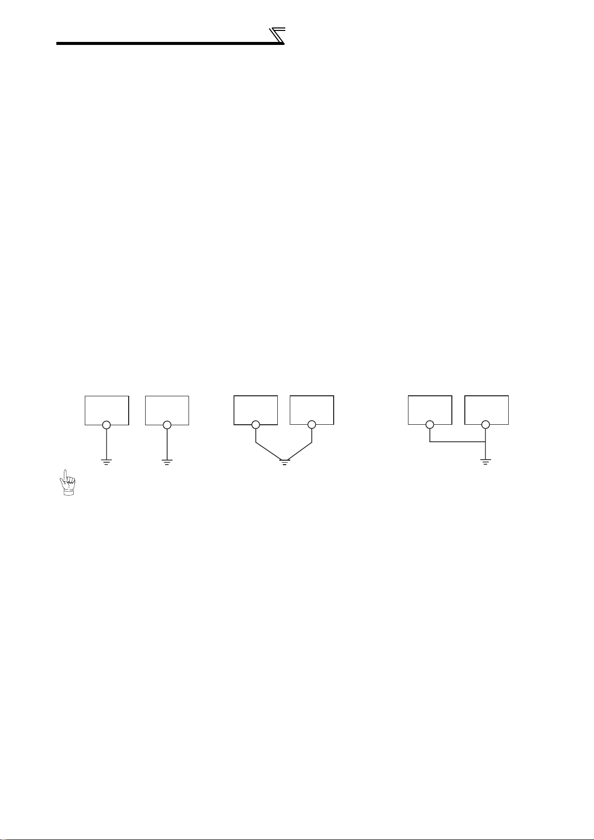
2)Earthing methods and earthing work
As described previously, earthing is roughly classified into an electrical shock prevention type and a noiseaffected malfunction prevention type. Therefore, these two types should be discriminated clearly, and the
following work must be done to prevent the leakage current having the inverter's high frequency components
from entering the malfunction prevention type earthing:
(a) Where possible, use independent earthing for the inverter. If independent earthing (I) is impossible, use
joint earthing (II) where the inverter is connected with the other equipment at an earthing point. Joint
earthing as in (III) must be avoided as the inverter is connected with the other equipment by a common
earth cable.
Also a leakage current including many high frequency components flows in the earth cables of the inverter
and inverter-driven motor. Therefore, they must use the independent earthing method and be separated
from the earthing of equipment sensitive to the aforementioned noises.
In a tall building, it will be a good policy to use the noise malfunction prevention type earthing with steel
frames and carry out electric shock prevention type earthing in the independent earthing method.
(b) This inverter must be earthed. Earthing must conform to the requirements of national and local safety
regulations and electrical codes. (JIS, NEC section 250, IEC 536 class 1 and other applicable standards).
(c) Use the thickest possible earth cable. The earth cable should be of not less than the size indicated in the
above table.
(d) The grounding point should be as near as possible to the inverter, and the ground wire length should be as
short as possible.
(e) Run the earth cable as far away as possible from the I/O wiring of equipment sensitive to noises and run
them in parallel in the minimum distance.
Inverter
Class C grounding
400V class
Other
equipment
Inverter
Other
equipment
400V class
Class C grounding
Inverter
400V class Class C grounding
equipment
Other
For use in compliance with the European Directive (Low Voltage Directive), refer to the Instru ction Manual (bas ics).
8
Main circuit terminal specifications
(3) Total wiring length
The wiring length should be 500m maximum.
(The overall wiring length for connection of multiple motors should be within the value in the table below.)
Pr. 72 PWM frequency selection setting
(carrier frequency)
2 (2kH) or less
3 (3kHz), 4 (4kHz) 200m 300m 500m
5 (5kHz) to 9 (9kHz) 100m
10 (10kHz) or more 50m
00023 00038
300m 500m 500m
00052 or
more
Total wiring length (00038 or more)
500m or less
300m
300m
300m + 300m = 600m
When driving a 400V class motor by the inverter, surge voltages attributable to the wiring constants may occur at
the motor terminals, deteriorating the insulation of the motor.
Refer to page 36 for measures against deteriorated insulation.
·
1
WIRING
9

Control circuit specifications
1.4 Control circuit specifications
1.4.1 Control circuit terminals
indicates Pr. 178 to Pr. 196 (I/O terminal function selection) (Refer to page 85.)
(1) Input signals
Terminal
Symbol
Type
STF
STR
STOP
RH,
RM, RL
JOG
RT
MRS Output stop
RES Reset
Contact i nput
AU
CS
SD
PC
Terminal
Name
Forward
rotation start
Reverse
rotation start
Start selfholding
selection
Multi-speed
selection
Jog mode
selection
Second
acceleration/
deceleration
time
selection
Terminal 4
input selection
PTC input
Selection of
automatic
restart after
instantaneous
power failure
External
transistor
common,
contact input
common
(sink)
24VDC
power supply,
contact input
common
(source)
Description
Turn on the STF signal to start forward
rotation and turn it off to stop.
Turn on the STR signal to start reverse
rotation and turn it off to stop.
Turn on the STOP signal to self-hold the start signal . 85
Multi-speed can be sele ct ed according to the combinat ion of
RH, RM and RL signals.
Turn on the JOG signal to select Jog operation (initial setting)
and turn on the start signal to start Jog op er at io n.
Turn on the RT signal to select secon d acceleration/
deceleration time.
When the second functi on such as "second torque boo st " and
"second V/F (base frequen cy) " ar e set, turning on the RT
signal sel ects these func t ions.
Turn on the MRS signal (20ms or more) to s top th e i nverter
output.
Use to shut off the inverter output when stopping the motor by
electromagnetic bra ke.
Used to reset alarm output pr ovided when protective func tion
is activated.
Turn on the RES signal for more than 0.1s, then turn it off.
Initial setting is for reset always. By setting Pr.75, reset can be
set to enabled only at an inverter alarm occurrence. Recover
about 1s after reset is cancelled.
T erminal 4 is made valid only when the AU signal is turned on. (The
frequency setting signal can be set between 4 and 20mADC.)
Turning the AU signal on makes terminal 2 (voltage input) invalid.
AU terminal is used as PTC input term inal (thermal protection
of the motor). When using it as PTC input terminal, set the AU/
PTC switch to PTC.
When the CS signal is left on, the inverter restarts automatically at
power restora tion. Note that restart settin g is necessary for this
operation. In the init ial se ttin g, a res t ar t is disa b led .
(Refer to Pr.57 Restart coasting time, page
Common terminal for contact input terminal and terminal CA
for sink logic.
Common output terminal fo r 24 VDC 0. 1A power supply (PC
terminal).
Isolated from terminals 5 and SE.
When connecting the transistor output (open collector output),
such as a programmable controller (PLC), connect the external
power supply common for transistor output to this terminal to
prevent a malfunction caused by undesirable currents.
Can be used as 24VDC 0.1A power supply.
When source logic ha s bee n selected, this terminal ser ves as
NO contact input common.
When the STF and
STR signals are turned
on simultaneously, the
stop command is given.
109
)
Rated
Specifications
Input resistance
4.7kΩ
Voltage at
opening: 21 to
27VDC
Contacts at
short-circuited: 4
to 6mADC
-------------------- —
Power supply
voltage range 22
to 26VDC
Current
consumption
100mA
Refer to
85
85
85
85
85
85
125
79
85
17
10
Control circuit specifications
Terminal
Symbol
Type
10E
10
2
4
Frequency setting
1
5
Terminal
Name
Frequency
setting
power
supply
Frequency
setting
(voltage)
Frequency
setting
(current)
Frequency
setting
auxiliary
Frequency
setting
common
Description
When connecting the frequency setting potentiometer at an
initial status, connect it to termi nal 10.
Change the input specifications when connecting it to terminal
10E. (Refer to Pr.73 Analog input selection in page 127.)
Inputting 0 to 5VDC (or 0 to 10V, 0 to 20mA) provides the
maximum output frequency at 5V (10V, 20mA) and makes
input and output proportional. Use Pr.73 to switch from among
input 0 to 5VDC (initial setting ), 0 to 10VDC, and 0 to 20mA.
Inputting 0 to 20mADC (or 0 to 5V, 0 to 10V) provides the
maximum output frequency at 20mA (5V, 10V) makes input
and output proportional. This input signal is valid only when the
AU signal is on (terminal 2 input is invalid). Use Pr.267 to
switch between the input 0 t o 20m A (initial value) and 0 to
5VDC, 0 to 10VDC.
Inputti ng 0 t o 5 VDC or 0 to 1 0VD C ad ds t hi s si gn al t o t er m in al
2 or 4 frequency setting signal. Use Pr.73 to switch bet w een
the input 0 to ±5VDC and 0 to ±10 VD C (ini t ial sett in g) .
Common terminal for frequency setting signal (terminal 2, 1 or
4) and analog output terminal AM . Do not earth.
Rated
Specifications
10VDC±0.4V
Permissible load
current 10mA
5.2VDC±0.2V
Permissible load
current 10mA
Voltage input:
Input resistance
10kΩ ± 1kΩ
Maximum
permissible
voltage 20VDC
Current input:
Input resistance
250Ω ± 2%
Maximum
permissible
current 30mA
Input resistance
10kΩ ± 1kΩ
Maximum
permissible voltage
± 20VDC
-------------------- 12 5
Refer to
125
125
125
125
125
(2) Output signals
Terminal
Symbol
Type
A1,
B1,
C1
Relay
A2,
B2,
C2
RUN
SU
OL Overload alarm
Open collector
IPF
FU
SE
Terminal
Name
Relay output 1
(alarm ou tput)
Relay output 2 1c Contact output 91
Inverter
running
Up to
frequency
Instantaneous
power failure
Frequency
detection
Open collector
output common
Description
Changeover contact output indicates that the inverter
protective function has activated and the output stopped.
Abnormal: No conduction across B-C (Across A-C
Continuity), Normal: Across B-C Continuity (No conduction
across A-C)
Switched low when the inverter outpu t
frequency is equal to or higher than th e
starting frequency (initial value 0.5 Hz).
Switched high during stop or DC
injection brake operation.
Switched low when the output fr equency
reaches within the range of ±10% (initial
value) of the set frequency. Switched
high during acceleration/decelera tion
and at a stop.
Switched low when stall prevention is
activated by the stall preven tion
function. Switched high when stall
prevention is cancelled.
Switched low when an instantaneous
power failure and under voltage
protections are activat ed.
Switched low when the inverter
output frequency is equal to or higher
than the preset detected frequency
and high when less than the pre set
detected frequency.
Common terminal for terminals RUN, SU, OL, IPF, FU -------------------- -----
*1
*1
Alarm code (4bit)
output (Refer to page
116.)
*1
*1
*1
Rated
Specifications
Contact
capacity:
230VAC 0.3A
(Power
factor=0.4)
30VDC 0.3A
Permissible load
24VDC 0.1A
Refer to
91
91
91
91
91
91
1
WIRING
11
Control circuit specifications
Terminal
Symbol
Type
CA
Analog
AM
*1 Low indicates that the open collector output transistor is on (conducts).
High indicates that the trans istor is off (does not conduct).
*2 Not output during inverter reset.
Terminal
Name
Analog current
output
Analog voltage
output
Description
Select one e.g. output freq uency
from mon i tor items.
The output signal is propo rti ona l to
the magnitude of the corresponding
monitoring item.
*2
(3) Communication
Terminal
Symbol
Type
PU
connector
TXD+
RS-485
TXDRXD+
RXD-
RS-485 terminal
SG Earth
Terminal
Name
PU
connector
Inverter
transmission
terminal
Inverter
reception
terminal
Description
With the PU connector, communicatio n can be made through RS-485.
(for connection on a 1:1 basi s only)
. Conforming standard : RS-485
. Transmission format : Multidrop
. Communication speed : 4800 to 38400bps
. Overall length : 500m
With the RS-485 termin al , c om m unication can be made throu gh R S- 485.
Conforming standard : RS-485
Transmission format : Multidrop link
Communication spee d : 300 to 38400bps
Overall length : 500m
Output item:
Output frequency
(initial setting)
Rated
Specifications
Load impedance
200Ω to 450Ω
Output signal 0 to
20mADC
Output signal 0
to 10VDC
Permissible load
current 1mA
(load impedance
10kΩ or more)
Resolution 8 bit
Rated
Specifications
Refer to
104
104
Refer to
156
158
1.4.2 Control circuit terminal layout
RL
C2B2A2C1B1A1
(1) Wiring method
Loosen the terminal screw and insert the cable into the terminal.
Screw Size: M3 Tightening Torque: 0.5N·m to 0.6N·m
Cable size: 0.3mm
Screwdriver:Small flat-blade screwdriver (Edge thickness: 0.4mm/
Edge width: 2.5mm)
CAUTION
Undertightening can cause cable disconnection or ma l fu nct i on .
Overtightening can cause a short circuit or malfunction due to
damage to the screw or unit.
2
to 0.75mm
2
CA SD PC
STOP
RT
AURHRM
RES STF STR PC
OLIPFSURUNSE14521010EAMPC
FU
MRS
JOG CS
Cable stripping size
6mm
Wire the stripped cable after twisting it to
prevent it from becoming loose. In addition, do
not solder it. *
12

Control circuit specifications
(2) Common terminals of the control circuit (PC, 5, SE)
Terminals PC, 5, and SE are all common terminals (0V) for I/O signals and are isolated from each other.
Terminal PC is a common terminal for the contact input terminals (STF, STR, STOP, RH, RM, RL, JOG, RT, MRS,
RES, AU, CS).
The open collector circuit is isolated from the internal control circuit by photocoupler.
Terminal 5 is a common terminal for frequency setting signal (terminal 2, 1 or 4), analog current output terminal (CA)
and analog output terminal AM.
It should be protected from external noise using a shielded or twisted cable.
Terminal SE is a common terminal for the open collector output terminal (RUN, SU, OL, IPF, FU).
The contact input circuit is isolated from the internal control circuit by photocoupler.
(3) Signal inputs by contactless switches
The contacted input terminals of the inverter (STF, STR, STOP,
RH, RM, RL, JOG, RT, MRS, RES, AU, CS) can be controlled
using a transistor instead of a contacted switch as shown on the
right.
PC
Inverter
+24V
STF, etc.
External signal input using transistor
R
1.4.3 Wiring instructions
1) Use shielded or twisted cables for connection to the control circuit terminals and run them away from the main
and power circuits (including the 200V relay sequence circuit).
2) Use two or more parallel micro-signal contacts or twin
contacts to prevent a contact faults when using contact inputs
since the control circuit input signals are micro-currents.
Micro signal contacts Twin contacts
3) Do not apply a voltage to the contact input terminals (e.g. STF) of the control circuit.
4) Always apply a voltage to the alarm output terminals (A, B, C) via a relay coil, lamp, etc.
5) It is recommended to use the cables of 0.75mm
If the cable gauge used is 1.25mm
2
or more, the front cover may be lifted when there are many cables running
or the cables are run improperly, resulting in an operation panel contact fault.
6) The wiring length should be 30m maximum.
Wiring of the control circuit of the 01800 or more
For wiring of the control circuit of the 01800 or more, separate away from wiring of the main circuit.
Make cuts in rubber bush of the inverter side and lead wires.
2
gauge for connection to the control circuit terminals.
1
WIRING
Rubber bush
(view from the inside)
Make cuts along the lines inside with
a cutter knife and such.
<Wiring>
13
Control circuit specifications
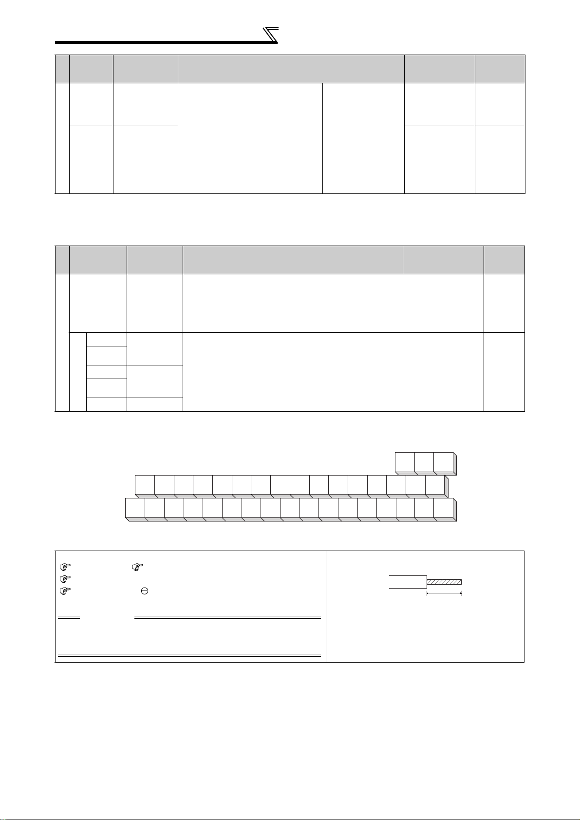
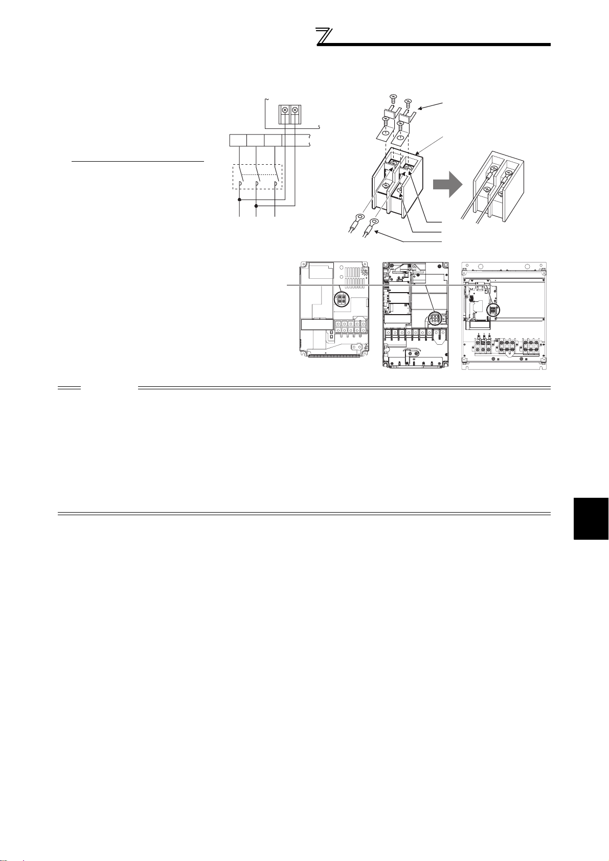
1.4.4 When connecting the control circuit and the main circuit separately
to the power supply (separate power)
<Connection diagram> When the protected circuit is activated, opening of the electromagnetic
MC
Inverter
R/L1
S/L2
T/L3
R1/L11
S1/L21
Remove the jumper
• FR-F740-00023 to 00126-EC
contactor (MC) on the inverter power supply side results in power loss in
the control circuit, disabling the alarm output signal retention. Terminals
R1/L11 and S1/L21 are provided to hold an alarm signal. In this case,
connect the power supply terminals R1/L11 and S1/L21 of the control
circuit to the primary side of the MC.
1)Loosen the upper screws.
2)Remove the lower screws.
3)Remove the jumper
4)Connect the separate
power supply cable for the
control circuit to the lower
terminals (R1/L11, S1/L21).
•FR-F740-00170, 00250-EC
1)Remove the upper screws.
2)Remove the lower screws.
3)Remove the jumper.
4)Connect the separate power
supply cable for the control
circuit to the upper terminals
(R1/L11, S1/L21).
3)
1)
2)
4)
R1/L11
R/L1
S/L2
T/L3
S1/L21
Main circuit terminal block
3)
1)
R1/L11
2)
S1/L21
R1/L11
S1/L21
R1/L11
S1/L21
14
4)
R/
S/
L1
T/
L2
L3
Main circuit
terminal block
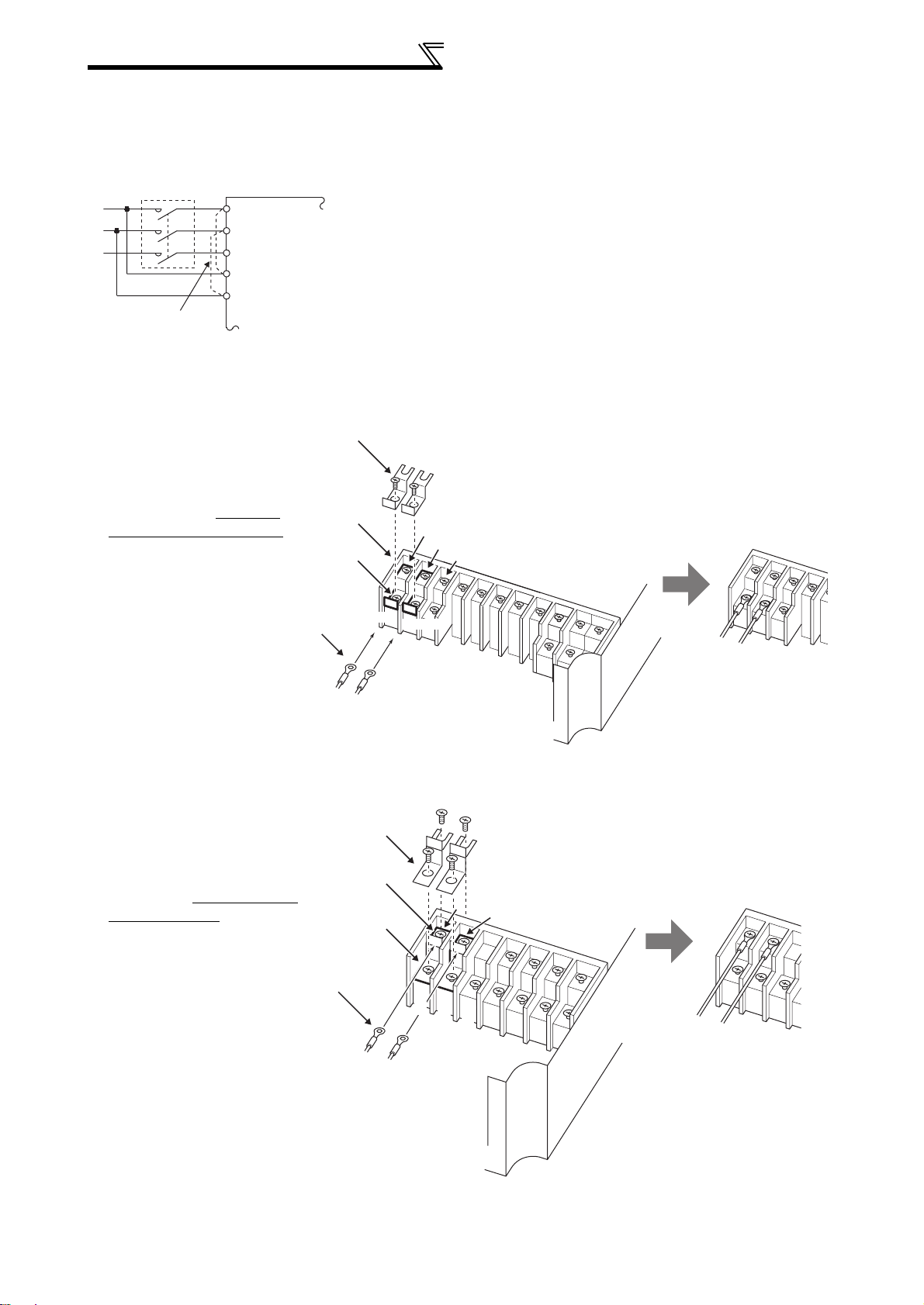
• FR-F740-00310 to 02160-EC
1)Remove the upper screws.
2)Remove the lower screws.
3)Pull the jumper toward you to
remove.
4)
Connect the separate power supply
cable for the control circuit to the
upper terminals (R1/L11, S1/L21)
Never connect the power cable to
the terminals in the lower stand.
Doing so will damage the inverter.
.
MC
R/L1
S/L2
T/L3
R1/
L11
S1/
L21
Power supply
terminal block
for the control circuit
Control circuit specifications
3)
Power supply terminal block
for the control circuit
R1/L11
S1/L21
Main power supply
1)
2)
4)
00310, 00380 000470, 00620 00770 to 02160
Power supply
terminal block for
the control circuit
VUW
CAUTION
1. Do not turn off the co ntrol pow er (t ermin als R1/L11 and S1/L21) with the m ain circu it pow er (R/L 1, S /L2, T /L3) on. Do ing
so may damage the inverter.
2. Be sure to use the inverter with the jumpers across terminals R/L1-R1/L11 and S/L2-S1/L21 removed when supplying
power from other sources. The inverter may be dam aged if you do not remove the jum per.
3. The vo ltage sho uld be th e sam e as th at of th e main c ontrol c ircuit w hen th e control circuit p ower is suppl ied from o ther tha n the
primary side of the MC.
4. The power capacity is 60VA or more for 00380 or 80VA or more for 00470 to 02160 when separate power is supplied from R1/L11,
S1/L21.
5. When the power supp ly used w ith the control ci rcuit is differen t from the one us ed with th e main ci rcuit, m ake up a circuit
which will switch off the main circuit power supply terminals R/L1, S/L2, T/L3 when the control circuit power supply
terminals R1/L11, S1/L21 are switched off.
1
15
WIRING
Control circuit specifications
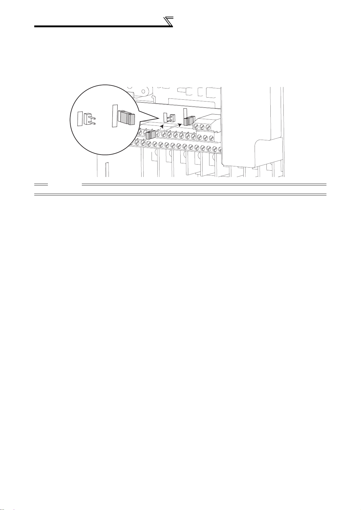
1.4.5 Changing the control logic
The input signals are set to source logic (SOURCE) when shipped from the factory.
To change the control logic, the jumper connector on the control circuit terminal block must be moved to the other
position.
(The output signals may be used in either the sink or source logic independently of the jumper connector position.)
E
C
K
IN
SINK
SOURCE
S
CAUTION
Turn off the inverter power before switch i ng a jum per connector.
R
U
O
S
16
Control circuit specifications
r
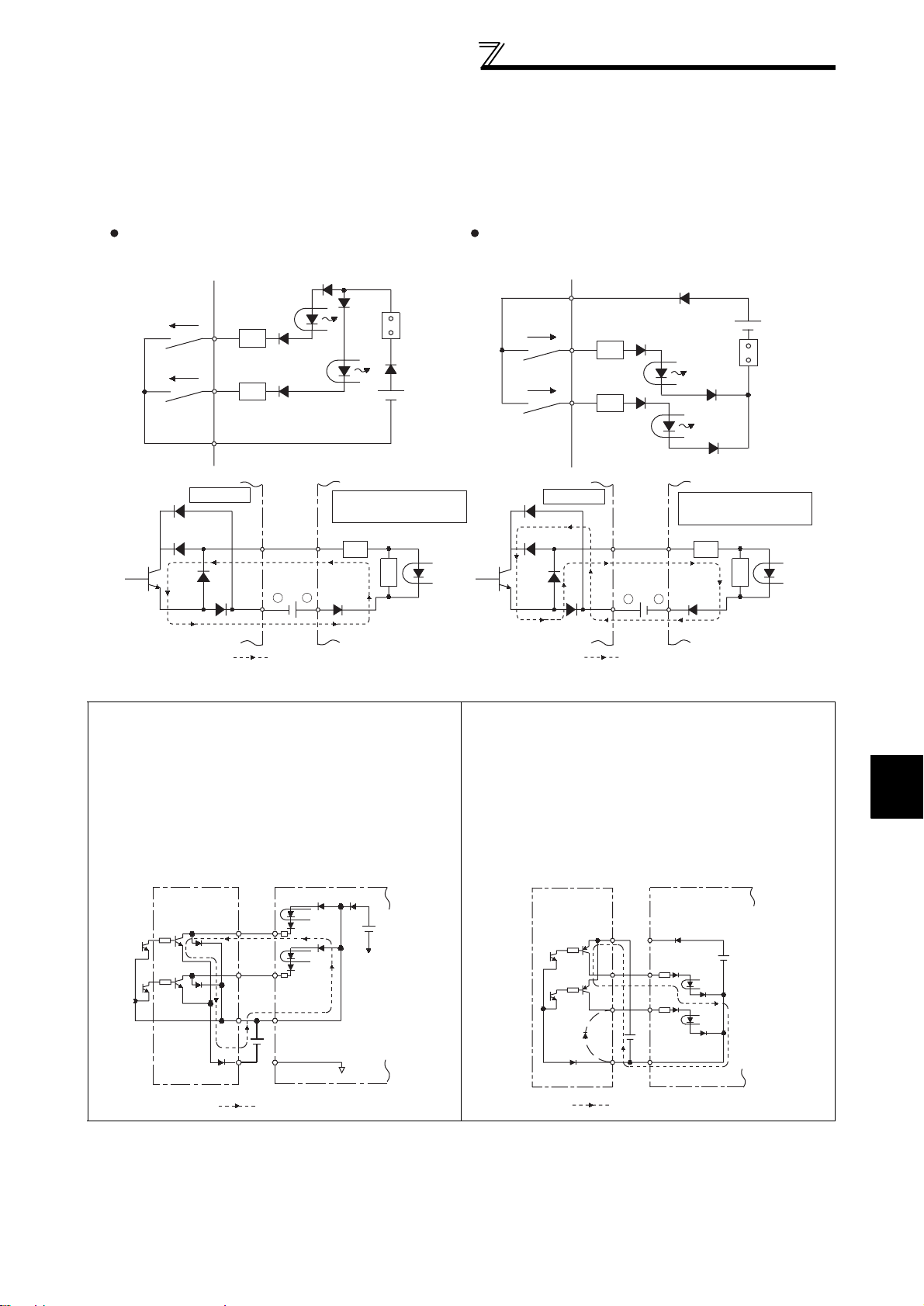
Sink logic and source logic
⋅ In sink logic, a signal switches on when a current flows from the corresponding signal input terminal.
Terminal SD is common to the contact input signals. Terminal SE is common to the open collector output
signals.
⋅ In source logic, a signal switches on when a current flows into the corresponding signal input terminal.
Terminal PC is common to the contact input signals. Terminal SE is common to the open collector output
signals.
Current flow concerning the input/output signal
when sink logic is selected
Sink logic
current
STF
STR
SD
Inverter
RUN
SE
R
R
1
-
+
9
24VDC
Current flow
DC input (sink type)
<Example: AX40>
R
R
Sink
connector
Current flow concerning the input/output signal
when source logic is selected
Source logic
PC
current
STF
R
STR
R
Inverter
RUN
SE
+
24VDC
Current flow
DC input (source type)
<Example: AX80>
1
R
-
9
Source
connecto
R
• When using an external power supply for transistor output
⋅ Sink logic type
Use terminal PC as a common terminal to prevent a
malfunction caused by undesirable current. (Do not
connect terminal SD of the inverter with terminal 0V
of the external power supply. When using terminals
PC-SD as a 24VDC power supply, do not install a
power supply in parallel in the outside of the inverter.
Doing so may cause a malfunction due to
undesirable current.)
AY40 type
transistor
output unit
10
1
2
9
9
STF
STR
24VDC
Inverter
24VDC
(SD)
PC
SD
Current flow
⋅ Source logic type
When using a transistor power supply for transistor
output, use terminal PC as a common to prevent
misoperation caused by undesirable current.
PC
STF
STR
24VDC
SD
Inverter
24VDC
(SD)
AY80 type
transistor
output unit
9
1
2
10
Current flow
1
WIRING
17
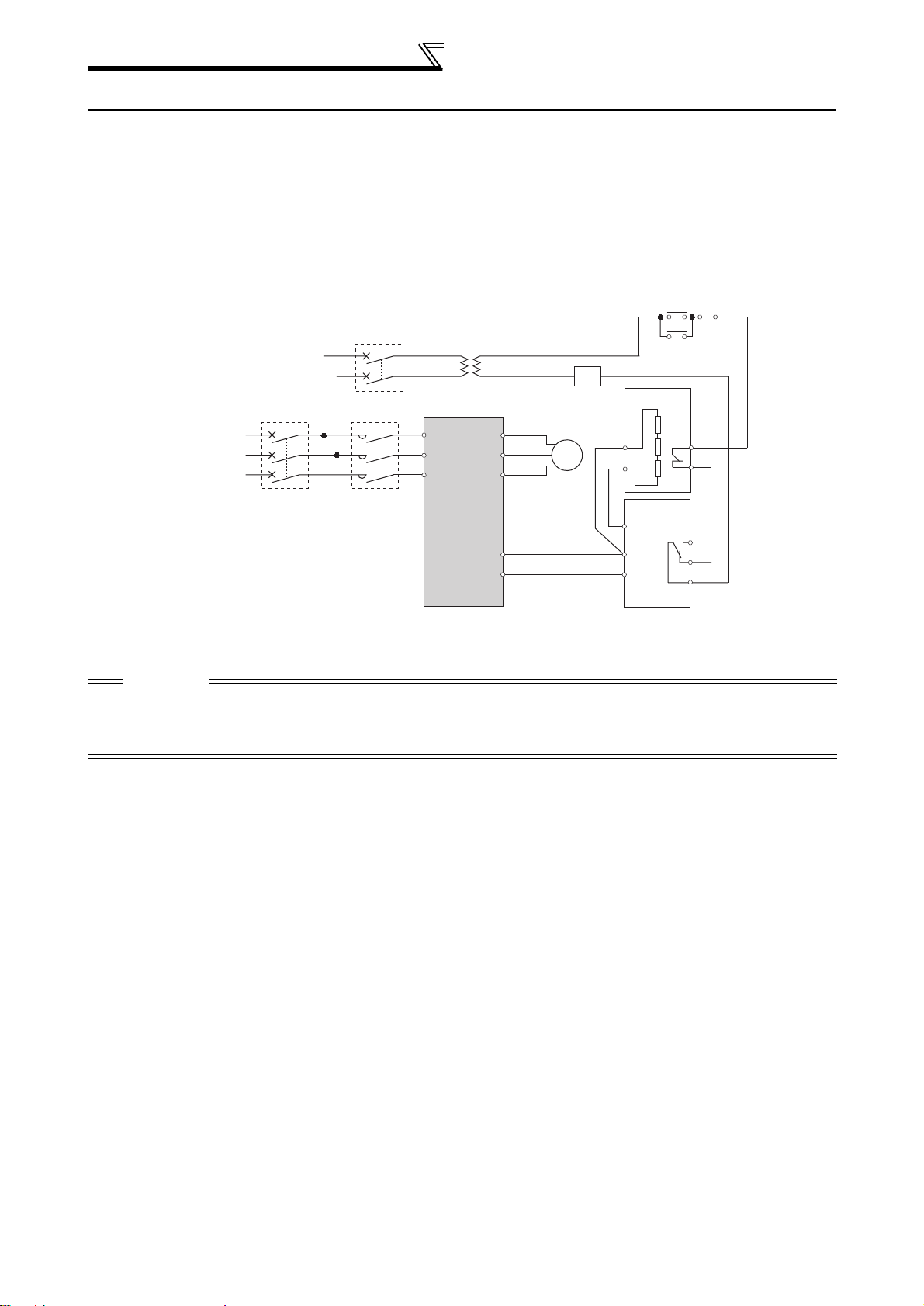
Connection of stand-alone option units
1.5 Connection of stand-alone option units
The inverter accepts a variety of stand-alone option units as required.
Incorrect connection will cause inverter damage or accident. Connect and operate the option unit carefully in
accordance with the corresponding option unit manual.
1.5.1 Connection of the brake unit (FR-BU)
When connecting the brake unit (FR-BU(H)) to improve the brake capability at deceleration, make connection as
shown below.
ON
T
*2
MC
MCCB
3-phase AC
power supply
*1 Connect the inverter terminals (P/+, N/-) and brake unit (FR-BU (H)) terminals so that their terminal
signals match with each other. (Incorrect connection will damage the inverter.)
*2 When the power supply is 400V class, install a step-down transformer.
MC
R/L1
S/L2
T/L3
Inverter
P/+
N/−
U
V
W
Motor
IM
*1
FR-BR
P
PR
FR-BU
PR
P
N
OFF
MC
TH1
TH2
HA
HB
HC
CAUTION
⋅ The wiring distance between the i nverter, brake unit(FR-BU) and resist or unit (FR-BR) should be within 5m. If twisted w i re s
are used, the distance should be within 10m.
⋅ If the transistors in the brake unit should become faulty, the resistor can be unusually hot, causing a fire. Therefore, install a
magnetic contactor on the inverterís input side to configure a circuit so that a current is shut off in case of fault.
18
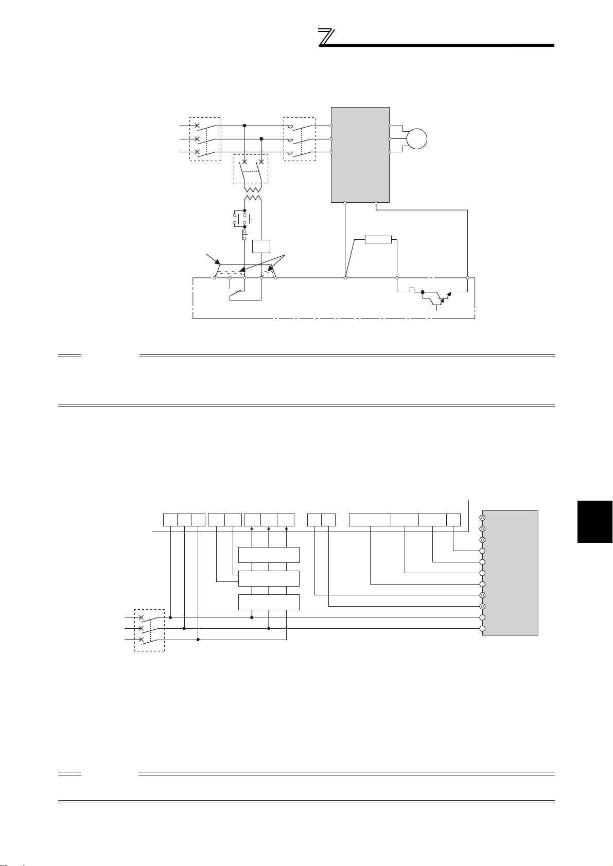
Connection of stand-alone option units
1.5.2 Connection of the brake unit (BU type)
Connect the brake unit (BU type) correctly as shown below. Incorrect connection will damage the inverter. Remove
the jumper across terminals HB-PC and terminals TB-HC of the brake unit and fit it to across terminals PC-TB.
Remove the
jumper
HCHBHA TB
OCR
MC
Inverter
R/L1
S/L2
T/L3
P/+
U
V
W
N/−
electrical-discharge
resistor
P
PR
Motor
IM
N
OCR
3-phase AC
power supply
MCCB
Fit a jumper
T
MC
PC
*1
OFF
ON
MC
brake unit (BU type)
*1 When the power supply is 400V class, install a step-down transformer.
CAUTION
1. The wiring distance between the inverter, brake unit and discharge resistor should be within 2m. If twisted wires are used,
the distance should be within 5m.
2. If the transistors in the brake unit should become faulty, the resistor can be unusually hot, causing a fire. Therefore, install
a magnetic contactor on th e inverter's power supply side to shut off a current in case of fault.
1.5.3 Connection of the high power factor converter (FR-HC)
When connecting the high power factor converter (FR-HC) to suppress power harmonics, perform wiring securely
as shown below.
Incorrect connection will damage the high power factor converter and inverter.
After making sure that the wiring is correct, set "2" in Pr. 30 Regenerative function selection. (Refer to page 83.)
High power factor converter (FR-HC)
P
N
Y1orY2 RDY RSO SE
3-phase AC
power supply
RST
MCCB
*1 Remove the jumpers across the inverter terminals R/L1-R1/L11, S/L2-S1/L21, and connect the control
circuit power supply to the R1/L11 and S1/L21 terminals. Always keep the power input terminals R/L1, S/
L2, T/L3 open. Incorrect connection will damage the inverter. (E.OPT (option alarm) will occur. (Refer to
page 236.))
Opposite polarity of terminals N/-, P/+ will damage the inverter.
*2 Do not insert the MCCB between terminals P/+ − N/- (P/+ − P/+, N/- − N/-).
*3 Use Pr. 178 to Pr. 189 (input terminal function selection) to assign the terminals used for the X10 (X11) signal.
(Refer to page 85.)
For communication where the start command is sent only once, e.g. RS-485 communication operation,
use the X11 signal when making setting to ho ld the mod e at occurr ence o f an ins tan t aneou s power f ailur e.
(Refer to page 83.)
MC1MC2
S4
R4
From FR-HCL02
MC2
MC1
T4
R4 S4 T4
S3
R3
External box
R2 S2 T2
FR-HCL01
S
R
T3
T
CAUTION
1. Use sink logic when the FR-HC is connected. The FR-HC cannot be connected when source logic (factory setting) is selected.
2. The voltage phases of terminals R/L1, S/L2, T/L3 and termin als R 4, S4, T4 mu st be m at ched.
Inverter
R/L1
S/L2
T/L3
SD
RES
X10
X11 *3
N/−
*2
P/+
R1/L11
S1/L21
*1
*3
*1
1
WIRING
19
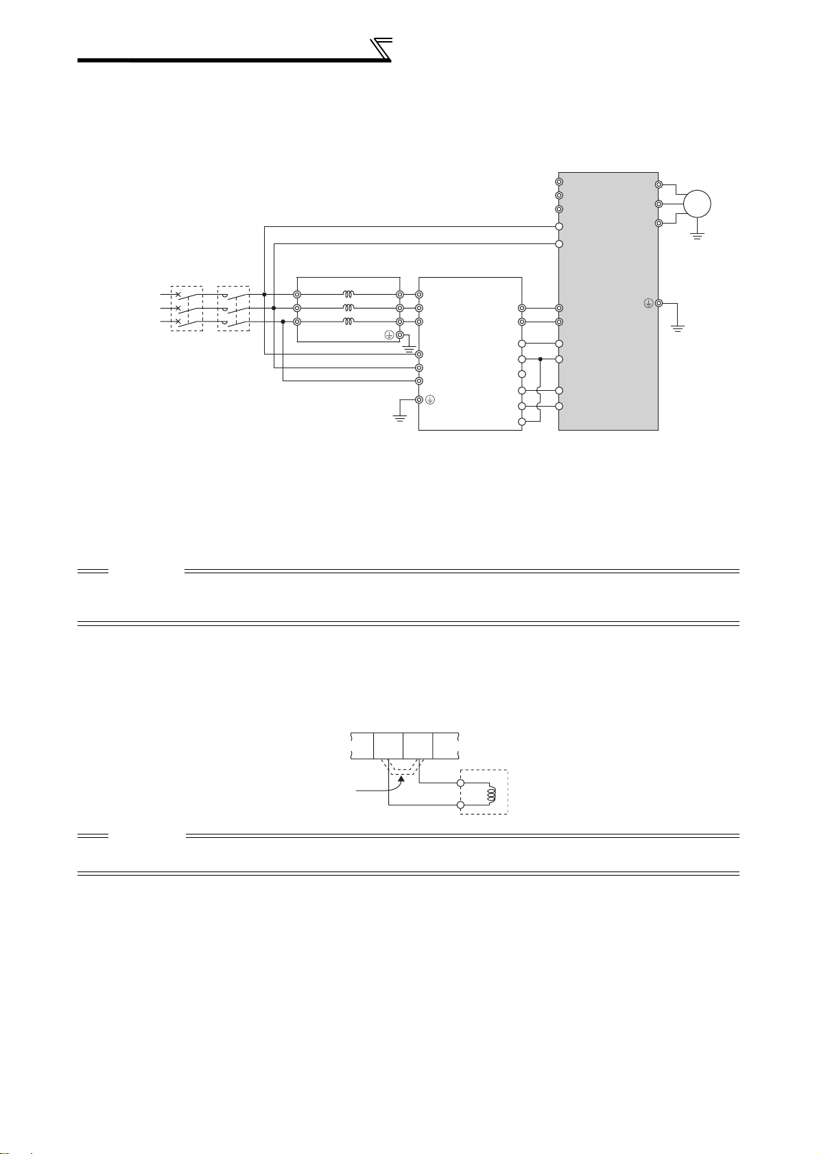
Connection of stand-alone option units
A
1.5.4 Connection of the power regeneration common converter (FR-CV)
When connecting the power regeneration common converter (FR-CV), make connection so that the inverter
terminals (P/+, N/-) and the terminal symbols of the power regeneration common converter (FR-CV) are the same.
After making sure that the wiring is correct, set "2" in Pr. 30 Regenerative function selection. (Refer to page 83.)
3-phase
C power
supply
R/L1
*1
S/L2
T/L3
R1/L11
Dedicated stand-alone
reactor (FR-CVL)
MCCB
*1 Remove the jumpers across terminals R/L1-R1/L11 and S/L2-S1/L21 of the inverter, and connect the
*2 Do not insert an MCCB between the terminals P/+ − N/- (between P/L+ − P/+, between N/L- − N/-).
*3 Assign the terminal for X10 signal using any of Pr. 178 to Pr. 189 (input terminal function selection).
*4 Be sure to connect the power supply and terminals R/ L11, S/L21, T/MC1.
MC1
control circuit power supply across terminals R1/L11-S1/L21. Always keep the power input terminals R/
L1, S/L2, T/L3 open. Incorrect connection will damage the inverter. (E.OPT (option alarm) will occur.
(Refer to page 236.)) Opposite polarity of terminals N/-, P/+ will dama ge the inverter.
(Refer to page 85)
Operating the inverter without connecting them will damage the power regeneration common converter.
R/L11
S/L21
T/L31
R2/L12
S2/L22
T2/L32
FR-CV type
Power regeneration
common converter
R2/L1
S2/L2
T2/L3
R/L11
S/L21
T/MC1
P/L+
N/L−
P24
*4
SD
RDYA
RDYB
RSO
SE
S1/L21
Inverter
P/+
*2
N/−
PC
SD
X10 *3
RES
U
V
W
IM
CAUTION
1. Use sink logic wh en the FR-CV is connected. The FR-CV cannot be conne cted when source logic (factory setting) is
selected.
2. The voltage phases of termi na l s R / L11, S/L21, T/MC1 and terminals R2/L1, S2/L2, T2/L3 must be matched.
1.5.5 Connection of the power factor improving DC reactor (FR-HEL)
When using the DC reactor (FR-HEL), connect it between terminals P1-P/+
In this case, the jumper connected across terminals P1-P/+ must be removed. Otherwise, the reactor will not exhibi t
its performance.
P/+
P1
FR-HEL
Remove
the jumper.
CAUTION
1. The wiring distance should be within 5m.
2. The size of the cables us ed sh ould be equal to or larger than that of the p ow er supply cables (R/L1, S/L2, T/L3 ).
20
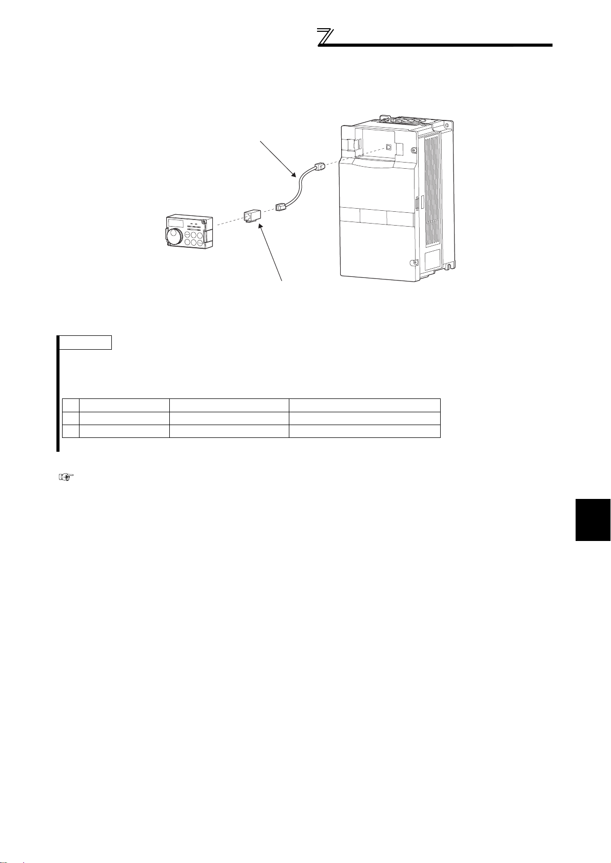
Connection of stand-alone option units
1.5.6 When connecting the operation panel using a connection cable
Using the optional parameter unit connection cable (FR-CB2), you can mount the operation panel (FR-DU07)
on the enclosure surface, for example, to perform remote operation or monitoring.
Parameter unit connection cable
(FR-CB2)(option)
Operation panel(FR-DU07)
Operation panel connection connector
(FR-ADP)(option)
Remarks
· Overall wiring length when the operation panel is connected: 20m
· Refer to the fo llowing when fabricati ng the cable on the user s i de.
Commercially avail able product examples
(as of November, 2003)
Product Type Maker
1) 10BASE-T cable SGLPEV-T 0.5mm × 4P * Mitsubis hi C able I ndustries, Ltd.
2) R J- 45 connector 5-554720-3 Tyco Electronics Corporation
* Do not use pins No. 2, 8 of the 10BASE-T cable.
Refer to page 161 for RS-485 communication.
1
WIRING
21

MEMO
22

PRECAUTIONS FOR USE
2
OF THE INVERTER
This chapter explains the "PRECAUTIONS FOR USE OF THE
INVERTER" for use of this product.
Always read the instructions before using the equipment
2.1 Panel design ...........................................................24
2.2 Precautions for use of the inverter ..........................28
2.3 Others .....................................................................29
1
2
3
4
5
23
 Loading...