

Mitsubishi FR-F720PJ-0.4K, FR-F720PJ-0.75KF, FR-F720PJ-0.4KF, FR-F720PJ-0.75K, FR-F740PJ-0.4K Series Manual
...
FACTORY AUTOMATION
INVERTER
FR-F700PJ
GREAT ENERGY SAVING WITH THE COMPACT BODY
• Suitable for Both the
General-purpose Motor
and the IPM Motor
• Inverter Control
for Energy Saving
• Wire and Space Saving
• Easy Operation and
Maintenance
• Optimum for Fan and
Pump Applications

Global Player
GLOBAL IMPACT OF
MITSUBISHI ELECTRIC
Through Mitsubishi Electric’s vision, “Changes for the Better“ are possible for a brighter future.
Mitsubishi Electric is involved in many areas including the following
We bring together the best minds to
create the best technologies. At
Mitsubishi Electric, we understand
that technology is the driving force of
change in our lives. By bringing
greater comfort to daily life, maximizing the efficiency of businesses and
keeping things running across
society, we integrate technology and
innovation to bring changes for the
better.
Energy and Electric Systems
A wide range of power and electrical products from generators to large-scale displays.
Electronic Devices
A wide portfolio of cutting-edge semiconductor devices for systems and products.
Home Appliance
Dependable consumer products like air conditioners and home entertainment systems.
Information and Communication Systems
Commercial and consumer-centric equipment, products and systems.
Industrial Automation Systems
Maximizing productivity and efficiency with cutting-edge automation technology.
2

Contents
Features
Connection Example
Standard Specifications
Outline Dimension Drawings
Terminal Connection Diagram, Terminal Specification Explanation
Explanation of Operation Panel, Parameter Unit, FR Configurator
Parameter List
Explanation of Parameters
Protective Functions
Options and peripheral devices
4
10
11
14
17
20
24
33
57
59
Precautions for Operation/Selection, Precautions for Peripheral Device Selection
Application to Motor
IPM Motor Control
Main differences and compatibilities with the FR-F500J series
Warranty, Global FA centers
70
76
80
84
86
3
The Easy and Compact Inverter
FR-F700PJ for
Energy Saving
Easy
and
Compact
Generalpurpose Motor
and IPM Motor
Control
Energy
Saving
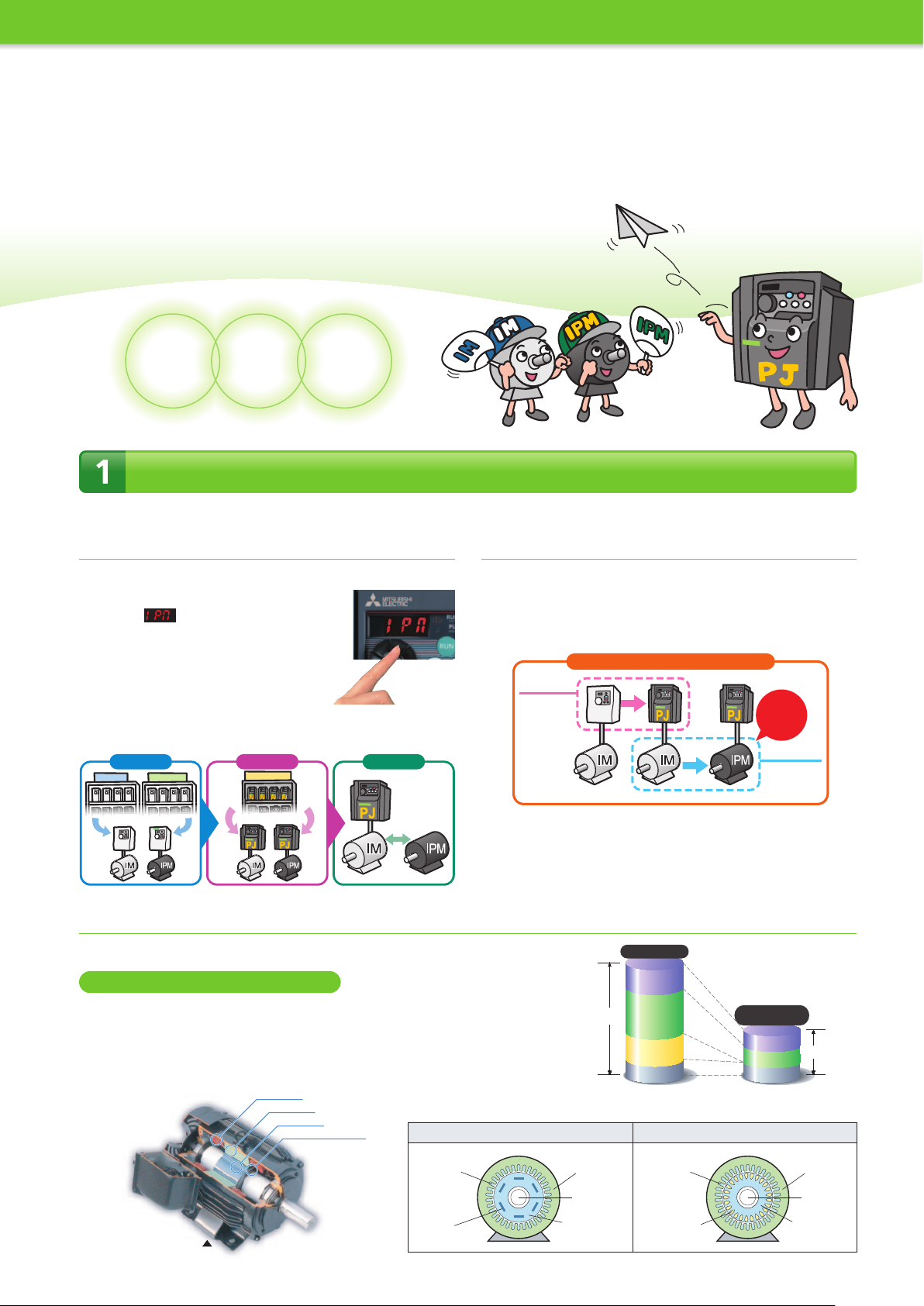
Suitable for Both the General-purpose Motor (Three-Phase Induction Motor) and the IPM Motor
(1)
The F700PJ series for both a general
-purpose motor (IM) and an IPM motor (IPM)
•The IM drive setting can be switched to IPM drive setting by
only one setting "12" (MM-EFS) in the
parameter . (Refer to page 80 for details.)
Never drive an IPM motor in the IM drive setting.
•One spare F700PJ inverter is enough for the two
types of motors (IM and IPM); the number of
required spare inverters is reduced by half.
•A push on the setting dial in the monitor mode
brings up the control setting (IM, IPM).
Before Now… Future
Inverter
Spare inverters for both
Inverter
Drive unit
Drive unit
FR-F700PJ
One spare inverter
IPM motor
control indicator
IM and IPM
driven by
one inverter
(2) Simple and reliable transition from
IM to IPM
There is no need to replace the whole system at once; replace the
inverters first, then replace the motors.
When the budget is limited, equipment investment can be made over
several stages.
Equipment Investment in Stages
1st Stage
First, replace
inverters.
Renewal
completed!
2nd Stage
Next, replace
motors.
(3) What is an IPM motor?
An IPM motor is a synchronous motor with strong permanent magnets embedded in its rotor.
Why is an IPM motor more efficient?
•No current flows to the rotor (secondary side), and no secondary copper loss is generated.
•Magnetic flux is generated with permanent magnets, and less motor current is required.
•Embedded magnets provide reluctance torque*, which can be used for driving.
*: Reluctance torque occurs due to magnetic imbalance in the rotor.
Stator coil
Stator core
Rotor core
Permanent magnet
IPM motor (MM-EFS)
4
IPM motor (synchronous motor)
Stator coil
(three-phase coil)
Permanent
magnets
General-purpose motor
Iron loss
Primary copper
loss (stator side)
100%
Secondary copper
loss (rotor side)
Other
SF-JR MM-EFS
[ Comparison of motor losses ]
* Example of 22kW motors
Premium high-efficiency
IPM motor
Iron loss
Primary copper
loss
Other
40%
Motor structure (section view)
General-purpose motor (induction motor)
Stator coil
(three-phase coil)
Rotor conductor
(copper or aluminum)
N
S
S
N
Stator core
Shaft
Rotor core
*Example of
6-pole motor
N
S
S
N
S
N
N
S
Stator core
Shaft
Rotor core
Inverter Control for Energy Saving
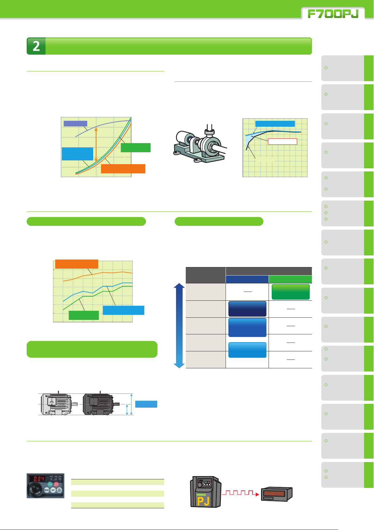
(1) Energy saving with speed control
The consumed power of a variable-torque load, such as fans, pumps,
and blowers, is proportional to the cube of its rotation speed.
This means that controlling the rotation speed to adjust the air
volume can lead to energy saving.
[Example of blower operation characteristic]
120
Damper control
100
80
60
High-performance
energy-saving
40
motor driven with inverter
Consumed power (%)
20
*1
0
*1: Rated motor output is 100%.
IPM motor driven with inverter
40 60 80 100
Air volume (%) [Comparison of
General-purpose motor
driven with inverter
Premium high-efficiency
Mitsubishi products]
(2) Energy saving with Optimum
excitation control
The optimum excitation control achieves the highest motor
efficiency. Further energy saving can be achieved for
applications such as fans and pumps with variable load torque.
(Refer to page 40 for the details.)
(Example: Pump)
(General-purpose motors)
100
Motor efficiency (%)
Optimum excitation control
More energy saving
V/F control
0 2020404060608080100
Motor load torque (%)
[Comparison of Mitsubishi products]
(3) To save more energy – the IPM motor control (MM-EFS series) is now available
High efficiency achieved with IPM motors
The IPM motors that have permanent magnets embedded in
their rotors are even more efficient than the high-performance
energy-saving motors.
[Comparison of efficiency]
100
Premium high-efficiency IPM
motor driven with inverter
95
90
85
80
75
Total efficiency (%)
70
65
General-purpose motor
driven with inverter
0.75 1.5 2.2 3.7 5.5 7.5 11 15
Motor capacity (kW)
High-performance energy-saving
motor driven with inverter
[Comparison of
Mitsubishi products]
Smooth replacement from a general-purpose
motor (with the same installation size)
The frame number of the MM-EFS is the same (same size) as
the Mitsubishi general-purpose motors (4-pole SF-JR/SF-HR
series). Replacement is easy as the installation sizes are
compatible.
IE4-equivalent efficiency level
The premium high-efficiency IPM motor "MM-EFS series"
provides efficiency that is equivalent to IE4 (super premium
efficiency), the highest efficiency class*
*2: As of October 2012
IEC 60034-30
Efficiency class
IE4
(super premium
HighEfficiencyLow
efficiency)*
IE3
(premium efficiency)
IE2
(high efficiency)
IE1
(standard efficiency)
Below the class
*3: The details of IE4 can be found in IEC 60034-31.
3
Efficiency of Mitsubishi motors
General-purpose motor
Super line
premium series
Super line
eco series
Super line series
(SF-PR)
(SF-HR)
(SF-JR)
2
.
IPM motor
Premium high-
efficiency IPM
(MM-EFS)
Features
•
Connection
•
example
Standard
•
specs.
Outline
•
dimensions
Terminal connection
•
diagrams
Terminal specs.
•
Operation panel
•
Parameter unit
•
FR Configurator
•
Parameter list
•
Parameter
•
details
Protective
•
functions
Options and
•
peripheral devices
Precaution on
•
selection and operation
Precautions on
•
peripheral device
selection
Compatible
•
motor
Same size
SF-JR 3.7kW MM-EFS371M4
(4) Check the energy saving eect at a glance
Energy saving monitor is available. The energy saving effect can
be checked using an operation panel, output terminal (terminal
FM), or network.
[List of monitored items for energy saving]
Example of the monitor
display for power saving
Power saving monitor (kW)
Power saving rate (%)
Power saving amount (kWh)
Power cost saving (yen)
Power saving average value (kW)
Power saving rate average value (%)
Power cost saving average value (yen)
Annual power saving amount (kWh)
Annual power cost saving (yen)
The output power amount measured by the inverter can be
output in pulses. The cumulative power amount can be easily
checked.*
*4: This function cannot be used as a meter to certify billings.
IPM motor
•
control
Difference and
•
compatibility with
FR-F500 (L) series
4
Warranty
•
Global FA centers
•
5
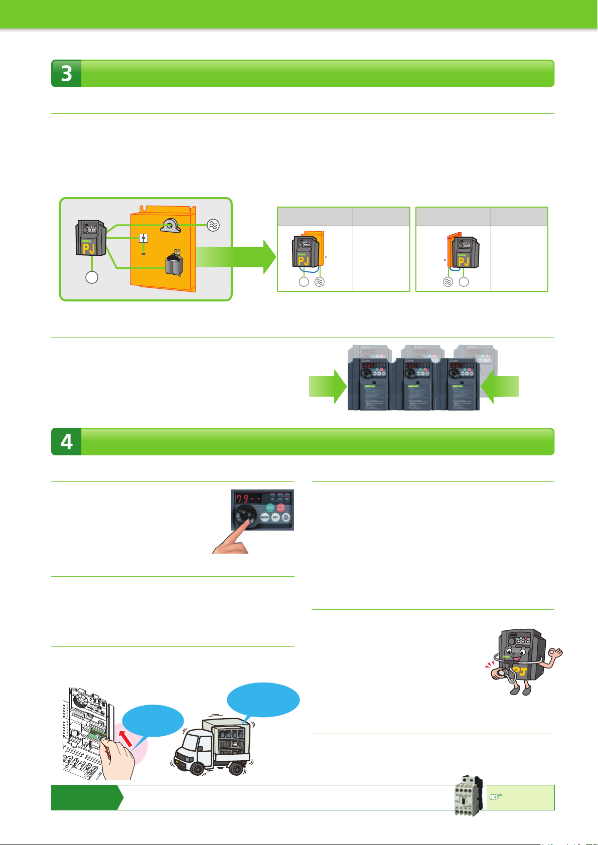
Wire and Space Saving
(1) A lineup of Filterpack models available
•The power factor improving DC reactor, common mode choke (line
noise filter), and capacitive filter (radio noise filter) are all essential for air
conditioning applications, and all of these are included in a Filterpack.
The Filterpack inverter models (FR-F70PJ-F) are also available. The
option wiring, which was necessary in the past, is no longer required.
•A Filterpack allows flexible installation and various layouts in the
enclosure. Smaller space is required for installation.
•Less wiring and smaller space also enable compliance with the Harmonic
Suppression Guidelines, the Architectural Standard Specifications
(Electrical Installation), and the Architectural Standard Specifications
(Machinery Installation) (2013 revisions) in Japan.
Back of the panel
M
Motor
Capacitive filter
(radio noise filter)
Power factor improving
Filterpack
Common
mode choke
DC reactor
Power
supply
Flexible
installation
M
Motor
*1: The area required for the separate installation of power factor improving DC reactor, common mode
choke (line noise filter), and capacitive filter (radio noise filter) with clearance around them.
(2) Space saving by the side-by-side installation
•Side-by-side installation is possible*2 and requires less space.
A DIN rail installation attachment (FR-UDA) option can be installed.
*2: Keep the surrounding air temperature of the inverter at 40 °C maximum.
Side-by-side installation is not available for Filterpacks.
Filterpack
Power
supply
Installation area
reduced by*
Approx.
72%
With
FR-F740PJ-3.7KF
1
Side of the panel
Installation area
reduced by*
1
Approx.
Filterpack
Power
supply
M
Motor
84%
With
FR-F740PJ-3.7KF
200 mm or less
depth at all capacities
Easy Operation and Maintenance
(1) Quick setting using the setting dial
•The adaptable scroll speed setting dial
allows for quick jumps or precise
increments based on turning speed.
•The non-slip treatment was applied to the
setting dial for easier turning.
(2)
Automatic parameter setting for specic applications
•Simple parameter setting (Pr.79 Operation mode selection)
•Communication setting for Mitsubishi HMI (GOT)
•Rated frequency change (60Hz → 50Hz)
(3)
Spring clamp terminals (control circuit terminals)
Spring clamp terminals*1 are adopted as control circuit terminals.
Spring clamp terminals are highly reliable and can be easily wired.
*1: The control circuit terminals are screw terminals.
Tensile strength
conforming to the
Easy wiring
only by inserting
wires
DIN standard
(4) Longer life parts
•The service life of the cooling fans is now 10 years*2. The service life
can be further extended by ON/OFF control of the cooling fan.
•Capacitors with a design life of 10 years*
2*3
are adapted.
(Surrounding air temperature of 105ºC for 5000 hours). With these
capacitors, the service life of the inverter is further extended.
*2: Surrounding air temperature: Annual average of 40ºC (free from corrosive gas, flammable
gas, oil mist, dust and dirt). The design life is a calculated value and is not a guaranteed
product life.
*3: Output current: 80% of the inverter rating.
(5) The leading-edge life diagnosis function
•The degree of deterioration of the main circuit capacitor, control
circuit capacitor, and inrush current limit circuit
can be diagnosed on the monitor.
•
Using the self-diagnosis function, the part life warning*4
can be output. With these warnings, the self-diagnosis
function prevents troubles from occurring.
*4: A warning is output when any of the main circuit capacitor, control circuit
capacitor, inrush current limit circuit, and cooling fan reaches its specified output level.
(6)
Enhanced communication function
•The Mitsubishi inverter protocol and MODBUS®RTU are selectable.
•The speed of RS-485 communication has been improved.
(Communication at 38.4kbps is available.)
Introducing the
Mitsubishi magnetic
contactor
•Offers a selection of small frames
•Offers a line-up of safety contactors
•Supports small loads (auxiliary contact)
•
Supports many international regulations as standard
Refer to page 68
for the selection.
6

Optimum for Fan and Pump Applications
(1) Enhanced PID control
•
To save energy in low-speed operation: PID output shutoff (sleep) function
•
To shorten the start-up time of PID control: PID automatic switchover function
•For air conditioning applications: Forward/reverse rotation switching
by external signals
•
To use various types of detectors: PID set point and measured value
outputs in voltage (0 to 5V / 0 to 10V)
and current (4 to 20mA)
(Example: Water-cooling pump for a showcase)
(2) Regeneration avoidance function
The operation frequency is automatically increased to prevent the
regenerative overvoltage fault from occurring. This function is useful
when a load is forcibly rotated by another fan in the duct.
(3)
Automatic restart after instantaneous power
failure function / ying start function
After an instantaneous power failure, the operation is re-startable from
the coasting motor speed.
Even if the rotation direction has been forcibly reversed, the operation
can be smoothly restarted in the original direction.
Coasts during
instantaneous
power failure
FeaturesOptionsPrecautionsMotor
example
Connection
specs.
Standard
Outline
dimensions
diagrams
Terminal connection
Terminal specs.
Parameter unit
FR Configurator
Operation panel
list
Parameter
The fan is rotated by the external force.
We need smooth start-up
of the motor.
Use the
flying start function.
The motor can be started smoothly even after the motor was
rotated by the external force (coasting).
This function can be set enabled by changing Pr.57 setting.
Power supply
Motor
speed
Output
frequency
Without the function With the function
Sudden change
of rotation
Parameters to adjust the acceleration time at a restart (Pr.611), to
detect the fan rotation direction (Pr.299), etc. are also available.
Power supply
Motor
speed
Output
frequency
Smooth
starting
We need continuous operations
without being interrupted by the
overvoltage protective function
(E.OV).
Use the
regeneration avoidance function.
When the external force accelerates rotation of the running motor
(regeneration), the motor may trip due to the overvoltage.
The regeneration avoidance function is available to increase the
frequency and avoid the regenerative condition.
This function can be set enabled by changing Pr.822 setting.
Motor
speed
Bus voltage
Output
frequency
Without the function With the function
OV trip
Parameters to start the regeneration avoidance operation (Pr.883)
and to adjust the response level (Pr.886) are also available.
Motor
speed
Bus voltage
Output
frequency
The trip does not occur and
the operation continues.
Parameter
descriptions
functions
Protective
control
IPM motor
CompatibilityWarranty
7
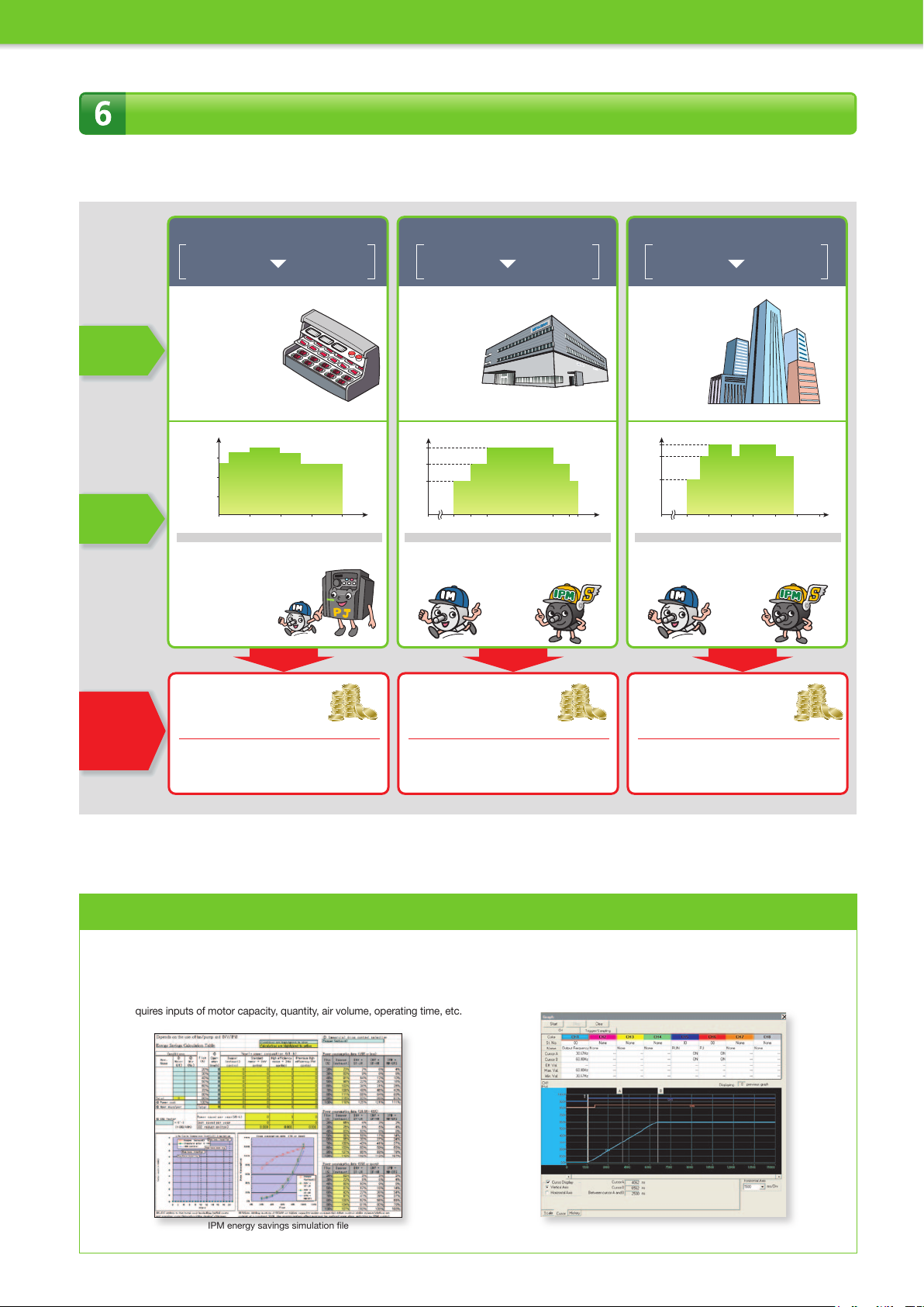
Application Example
Great energy saving eect obtained in medium airow
(When the electricity cost is 14 yen/kWh, and the CO2 emission is [1,000 kWh 0.555 ton - CO2 emission] )
Condition
Operation
patterns
Water-cooling pump for a showcase
Commercial power
supply (valve)
Inverter
[Units to drive]
• Water-cooling pump
3.7 kW × 1 unit
• Fans for the cooling tower
1.5 kW × 1 unit
• Freezer
11 kW × 3 unit
5.5 kW × 2 unit
3.7 kW × 1 unit
3.0 kW × 1 unit
Water volume (%)
100
75
50
25
• With commercial power supply
Approx. 0.15 million kWh
Approx. 2.17 million yen
• With inverter
Approx. 0.14 million kWh
Approx. 1.9 million yen
General-purpose
+
motor (SF-JR)
General-purpose
+
motor (SF-JR)
Time
WinterSpring Summer Fall
8760 hours/year 4745 hours/year5475 hours/year
Air conditioning in a Mitsubishi plant
Inverter
Inverter
[Units to drive]
• Ventilator
0.75 kW × 3 unit
1.5 kW × 1 unit
2.2 kW × 3 unit
• Air conditioner
15 kW × 1 unit
18.5 kW × 1 unit
30 kW × 2 unit
Air volume (%)
80
60
40
0 86
•
With general-purpose motor
Approx. 0.25 million kWh
Approx. 3.44 million yen
General-purpose
+
motor (SF-JR)
IPM motor
+
(MM-EFS)
10 18
• With IPM motor
Approx. 0.22 million kWh
Approx. 3.02 million yen
Time
2021
Air conditioning in a building
Inverter
Inverter
[Units to drive]
• Fans for air conditioning
5.5 kW × 10 unit
7.5 kW × 10 unit
3.7 kW × 100 unit
Air volume (%)
100
80
50
0 6 9 12 15 18 21 24
•
With general-purpose motor
Approx. 2.39 million kWh
Approx. 33.42 million yen
General-purpose
+
motor (SF-JR)
IPM motor
+
(MM-EFS)
• With IPM motor
Approx. 2.1 million kWh
Approx. 29.43 million yen
Time
(Annual) energy
saving effect
produced by
replacing to IPM
motors driven
with inverters
• Annual energy saving effect
(differences in the amount and cost)
Approx. 0.019 million kWh
Approx. 0.27 million yen
• Annual CO2 emission reduction
Approx. 0.019 million kWh
10.7 tons
• Annual energy saving effect
Approx. 0.03 million kWh
Approx. 0.42 million yen
• Annual CO
2 emission reduction
Approx. 0.03 million kWh
16.7 tons
Your best assistant — Mitsubishi inverter software
• IPM energy savings simulation file
The IPM energy savings simulation file calculates the energy saving effect
2 reduction rate achieved by replacing commercial power supply
and CO
(damper/valve control) operation with IPM motor operation by inverter. This
file requires inputs of motor capacity, quantity, air volume, operating time, etc.
• FR Configurator (FR-SW3-SETUP-WE) (Option)
Support tool for the inverter operations from start-up to maintenance.
• Annual energy saving effect
Approx. 0.28 million kWh
Approx. 3.99 million yen
• Annual CO
2 emission reduction
Approx. 0.28 million kWh
158 tons
IPM energy savings simulation file
8
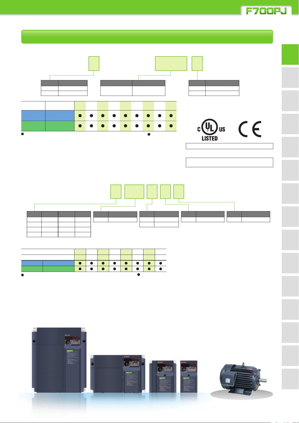
Line Up
• Inverter
FR-F740PJ-3.7K
FeaturesOptionsPrecautionsMotor
Symbol Voltage class
2
200 V class
4
400 V class
Power supply
specification
Three-phase
200 V
Three-phase
400 V
Precautions
•Never drive an IPM motor in the IM drive setting.
•Use the same IPM motor capacity as the inverter capacity.
•For IPM motor, use an MM-EFS or MM-EF series motor.
Please contact us regarding a combination with
other manufacturer's IPM motor.
Inverter
model
FR-F720PJ-K
FR-F720PJ-KF
FR-F740PJ-K
FR-F740PJ-KF
Symbol
0.4K to 15K
Inverter capacity
Represents
the capacity (kW).
• Premium high-efficiency IPM motor
MM-EFS71M4
Symbol
200 V class
400 V class
Precautions
•MM-EFS series IPM motors cannot be driven with commercial power supply.
•The total wiring length for an IPM motor should be 100 m or less.
•Only one IPM motor can be connected to an inverter.
Output Symbol Output
0.75 kW
7
1.5 kW
15
2.2 kW
22
3.7 kW
37
Rated output (kW)
Motor model
MM-EFS1M
MM-EFS1M4
11K
15K
55
75
5.5 kW
7.5 kW
11 kW
15 kW
0.7571.5
15
Symbol
Rated speed*
1M 1500 r/min
2.2223.7375.5557.57511
1
Symbol Voltage class
None
4
11K1515K
: To be released
15117.55.53.72.21.50.750.4
: To be released
200 V
400 V
Symbol Filterpack
None
F
*The inverter with Filterpack consists of an
inverter and a Filterpack.
The inverter carries the rating plate, "FR-F7
0PJ-KF," and the Filterpack carries the
rating plate "FR-BFP2-K".
Compatible with UL, cUL, EC Directives (CE marking)
•IPM motors and Filterpacks are not compatible with the above
regulations and directives.
Being RoHS compliant, the FR-F700PJ series inverters
are friendly to people and to the environment.
Symbol
Specification*
Q Class B
*1: Also applicable to an application with the rated speed of 1800r/min.
*2: The outdoor-type and class B are semi-standard models.
Please contact your sales representative for a special specification
such as the long-axis type, flange shape, and salt-proof type.
No
Yes*
2
Symbol
P1 Outdoor-type
Specification*
example
Connection
specs.
Standard
Outline
dimensions
diagrams
Terminal connection
Terminal specs.
Parameter unit
FR Configurator
Operation panel
list
Parameter
2
Parameter
descriptions
functions
Protective
control
IPM motor
CompatibilityWarranty
9
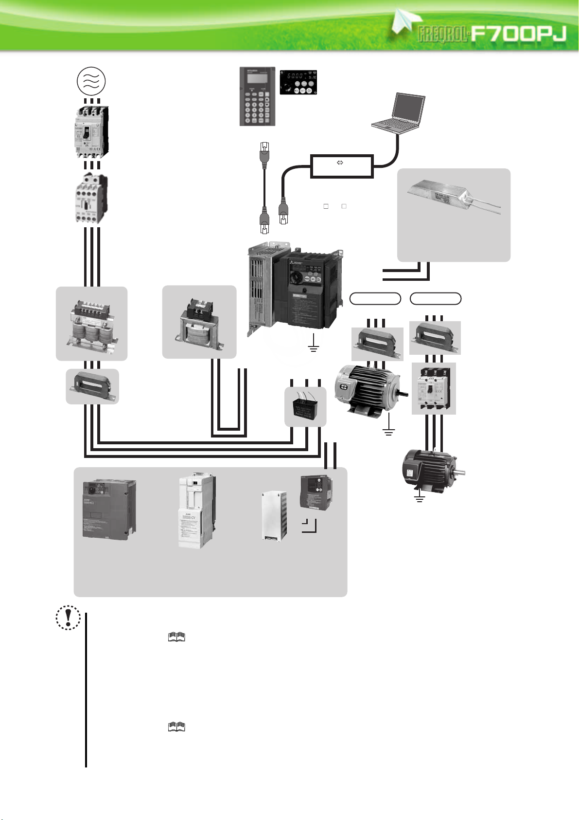
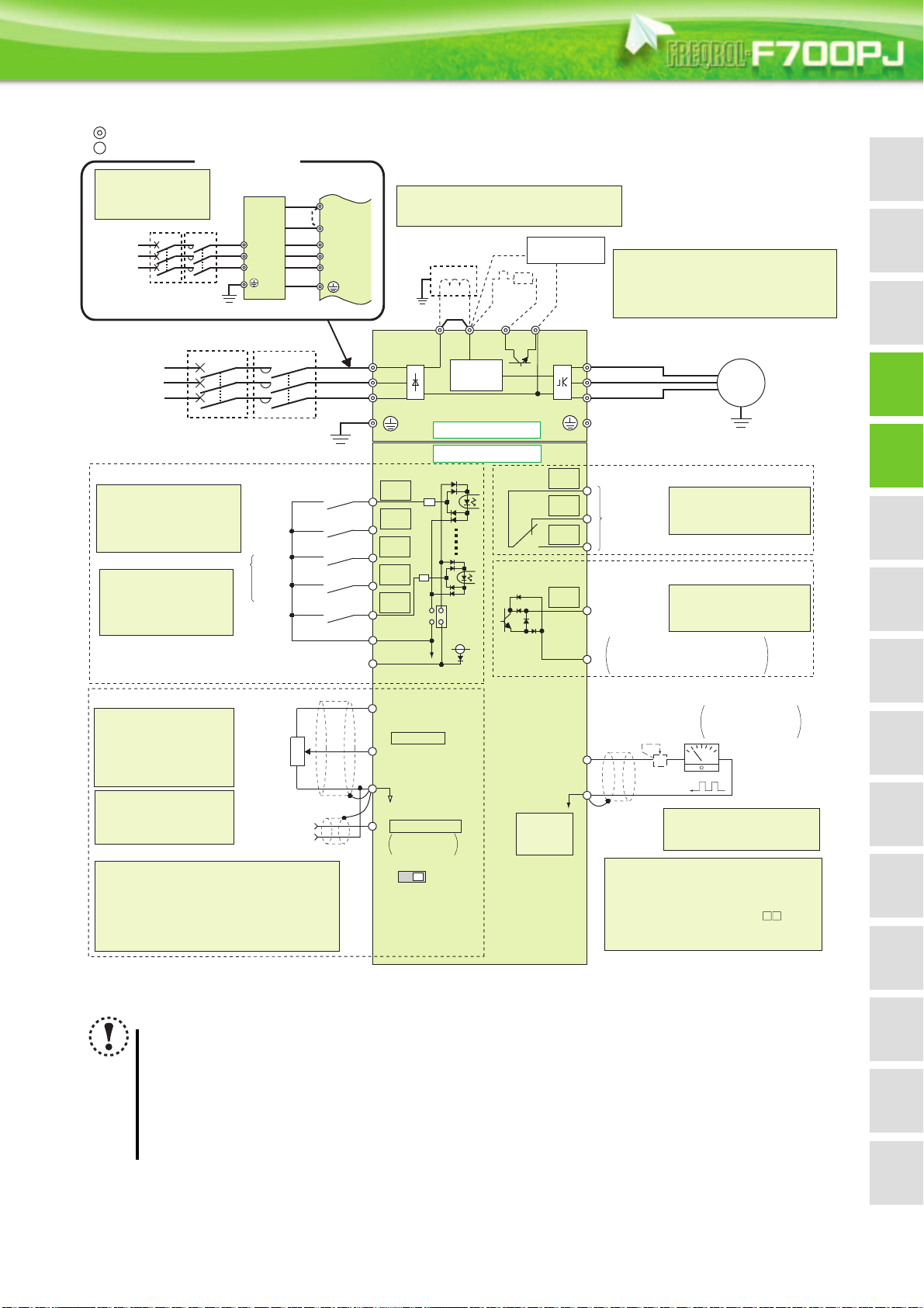
AC power supply
Use within the permissible power supply
specifications of the inverter. To ensure
safety, use a moulded case circuit breaker,
earth leakage circuit breaker or magnetic
contactor to switch power ON/OFF.
Magnetic contactor (MC)
Install the magnetic contactor to ensure
safety. Do not use this magnetic contactor
to start and stop the inverter. Doing so will
cause the inverter life to be shortened.
Noise filter
(ferrite core)
(FR-BSF01,
FR-BLF)
Earth (Ground)
Devices connected
to the output
Do not install a power
factor correction capacitor,
surge suppressor or noise filter (capacitor) on the output
side of the inverter. When installing a molded case
circuit breaker on the output side of the inverter,
contact each manufacturer for selection of the
molded case circuit breaker.
High power factor
converter (FR-HC2)
Power regeneration
common converter
(FR-CV)
R/L1 S/L2T/L3
P1
P/+
P/+
N/-
P/+
PR
Noise filter (ferrite core)∗
(FR-BSF01, FR-BLF)
Molded case circuit breaker (MCCB),
earth leakage circuit breaker (ELB),
or fuse
The breaker must be selected carefully
since an inrush current flows in the
inverter at power on.
* Not necessary if Filterpack (FR-BFP2) is used.
Earth (Ground)
To prevent an electric shock, always earth (ground)
the motor and inverter. For reduction of induction noise
from the power line of the inverter, it is recommended
to wire the earth (ground) cable by returning it to the
earth (ground) terminal of the inverter.
AC reactor (FR-HAL) DC reactor (FR-HEL)∗
Parameter unit
(FR-PU07)
Inverter
FR-F700PJ
Enclosure surface operation
panel (FR-PA07)
Noise filter
(capacitor)
(FR-BIF)
P/+
P/+
PR
PR
Brake unit
(FR-BU2)
Resistor unit (FR-BR)
Discharging resistor (GZG, GRZG)
UVW
VW
IM connection
IPM connection
Contactor
Example) No-fuse
switch (DSN type)
Install a contactor in
an application where
the IPM motor is
driven by the load
even at power-OFF
of the inverter. Do
not open or close
the contactor while
the inverter is
running (outputting).
Dedicated IPM
motor (MM-EFS,
MM-EF)
Earth
(Ground)
General-
purpose
motor
U
∗
Inverter (FR-F700PJ)
Filterpack (FR-BFP2)
The FR-F7 0PJ- F Filterpack
model has "F" at the end of its
model name. An inverter and a
Filterpack are enclosed with this series.
RS-232C - RS-485 converter is
required when connecting to PC
with RS-232C interface.
Earth
(Ground)
RS-485 RS-232C
Converter
Brake resistor
(FR-ABR, MRS type, MYS type)
(Refer to page 11)
(Refer to page 68)
(Refer to page 60)
(Refer to page 61)
(Refer to page 62)
(Refer to page 77)
(Refer to page 63)
(Refer to page 65)
(Refer to page 66)
(Refer to page 68)
(Refer to page 62)
(Refer to page 60)
(Refer to page 22)
(Refer to page 62)
(
Refer to
page
61)
Connection Example
NOTE
The life of the inverter is influenced by surrounding air temperature. Use the product within the permissible
surrounding air temperature. This must be noted especially when the inverter is installed in an enclosure.
(
Refer to chapter 1 of the Instruction Manual (Applied)
Wrong wiring might lead to damage of the inverter. The control signal lines must be kept fully away from the main
circuit to protect them from noise. (Refer to page 17)
Do not install a power factor correction capacitor, surge suppressor or noise filter (capacitor) on the inverter output
side. This will cause the inverter to trip or the capacitor and surge suppressor to be damaged. If any of the above
devices are connected, immediately remove them.
Electromagnetic wave interference
The input/output (main circuit) of the inverter includes high frequency components, which may interfere with the
communication devices (such as AM radios) used near the inverter. In this case, install the FR-BIF optional EMC filter
(capacitor) (for use in the input side only) or FR-BSF01 or FR-BLF noise filter (ferrite core) to minimize interference.
(
Refer to chapter 3 of the Instruction Manual (Applied))
Refer to the Instruction Manual of each option and peripheral devices for details of peripheral devices.
An IPM motor cannot be driven by the commercial power supply.
An IPM motor is a motor with permanent magnets embedded inside. High voltage is generated at the motor terminals while the
motor is running. Before closing the contactor at the output side, make sure that the inverter power is ON and the motor is stopped.
10
)
FeaturesOptionsPrecautionsMotor
Connection
example
Standard
specs.
Outline
dimensions
Parameter
list
Parameter
descriptions
Protective
functions
IPM motor
control
CompatibilityWarranty
Terminal connection
diagrams
Terminal specs.
Operation panel
Parameter unit
FR Configurator
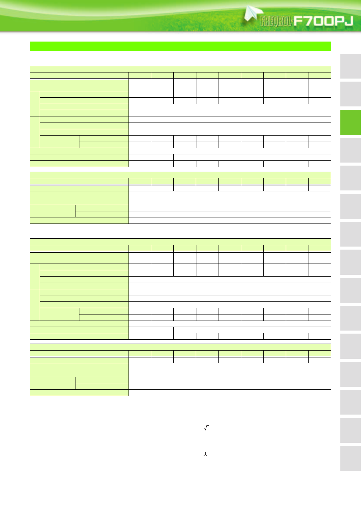
Standard Specifications
2
Rating
Three-phase 200V power supply
Model FR-F720PJ-K 0.4 0.75 1.5 2.2 3.7 5.5 7.5 11 15
Applicable general-purpose motor capacity
(kW)
Rated capacity (kVA)
Rated current (A)
Overload current rating
Output
Rated voltage
Rated input AC voltage/frequency
Permissible AC voltage fluctuation
Permissible frequency fluctuation
Power supply
Power supply
capacity (kVA)
Protective structure (JEM 1030)
Cooling system
Approximate mass(kg)
Without Filterpack
With Filterpack
Inverter
0.4 0.75 1.5 2.2 3.7 5.5 7.5 11 15
1.0 1.6 2.7 3.8 6.3 9.1 12.1 17.1 22.1
2.5 4.2 7.0 10.0 16.5 23.8 31.8 45 58
120% 60s, 150% 0.5s (inverse-time characteristics)
Three-phase 200 to 240V
Three-phase 200 to 240V 50Hz/60Hz
170 to 264V 50Hz/60Hz
±5%
1.2 2.1 4.0 5.0 8.8 12.0 17.0 20.0 27.0
0.8 1.2 2.6 3.4 5.5 8.4 11.0 16.0 19.0
Enclosed type (IP20)
Self-cooling Forced air cooling
0.8 1.0 1.4 1.4 1.8 3.6 3.6 6.5 6.5
Approximate mass(kg)
Power factor improving reactor
EMC filter
Protective structure (JEM 1030)
Three-phase 400V power supply
Applicable general-purpose motor capacity
(kW)
Protective structure (JEM 1030)
Cooling system
Approximate mass (kg)
Approximate mass (kg)
Power factor improving reactor
EMC filter
Protective structure (JEM 1030)
The applicable motor capacity indicated is the maximum capacity applicable for use of the Mitsubishi 4-pole standard motor. To use a dedicated IPM motor,
The rated output capacity assumes the following output voltages: 220V for the three-phase 200V and 440V for the three-phase 400V class.
The % value of the overload current rating indicated is the ratio of the overload current to the inverter's rated output current. For repeated duty, allow time for
The maximum output voltage does not exceed the power supply voltage.The maximum output voltage can be changed within the setting range. However,
The power supply capacity varies with the value of the power supply side inverter impedance (including those of the input reactor and cables).
Open type (IP00) for Filterpack.
The values in parentheses are calculated with 1 fundamental frequency power factor according to the Year 2013 Standard specification for public
The indicated leakage current is equivalent to one-phase of the three-phase three wire connection cable.
Filterpack
Model FR-BFP2-K 0.4 0.75 1.5 2.2 3.7 5.5 7.5 11 15
1.3 1.4 2.0 2.2 2.8 3.8 4.5 6.7 7.0
Install the DC reactor in the DC side. 93% to 95% of power supply power factor under 100%
Common mode choke
Capacitive filter
load (94.4%
Install a ferrite core on the input side
About 4mA of capacitor leakage current
Open type (IP00)
Inverter
Model FR-F740PJ-K 0.4 0.75 1.5 2.2 3.7 5.5 7.5 11 15
0.4 0.75 1.5 2.2 3.7 5.5 7.5 11 15
Rated capacity (kVA)
Rated current (A)
Overload current rating
Output
Rated voltage
Rated input AC voltage/frequency
Permissible AC voltage fluctuation
Permissible frequency fluctuation
Power supply
Power supply
capacity (kVA)
Without Filterpack
With Filterpack
0.9 1.7 2.8 3.8 6.2 9.1 12.4 17.5 22.5
1.2 2.2 3.7 5.0 8.1 12.0 16.3 23.0 29.5
120%60s, 150% 0.5s (inverse-time characteristics)
Three-phase 380 to 480V
Three-phase 380 to 480V 50Hz/60Hz
325 to 528V 50Hz/60Hz
±5%
1.1 2.2 4.2 4.8 8.6 12.0 17.0 20.0 28.0
0.7 1.3 2.7 3.3 5.4 8.5 11.0 16.0 19.0
Enclosed type (IP20)
Self-cooling Forced air cooling
1.3 1.3 1.4 1.5 1.5 3.3 3.3 6.0 6.0
Filterpack
Model FR-BFP2-HK 0.4 0.75 1.5 2.2 3.7 5.5 7.5 11 15
1.6 1.7 1.9 2.3 2.6 4.5 5.0 7.0 8.2
Install the DC reactor in the DC side. 93% to 95% of power supply power factor under 100%
Common mode choke
Capacitive filter
load (94.4%
Install a ferrite core on the input side
About 8mA of capacitor leakage current
Open type (IP00)
refer to page 77.
the inverter and motor to return to or below the temperatures under 100% load.
the pulse voltage value of the inverter output side voltage remains unchanged at about that of the power supply.
constructions (electric installation works), published by the Ministry of Land, Infrastructure, Transport and Tourism in Japan.
11

Common Specification
Control method
Output frequency range
Frequency setting
resolution
Frequency
accuracy
Speed control range
Voltage/frequency characteristics
Starting torque
Torque boost
Control specifications
Acceleration/deceleration time
setting
Regenerative braking torque
DC injection brake
Stall prevention operation level
Frequency setting
signal
Start signal
Input signal (five terminals)
Operational functions
Output signal
Open collector output (one
Operation specifications
terminal)
Relay output (one terminal)
Operating status
For meter
Pulse train output
(MAX 2.4kHz: one terminal)
Operation panel
Parameter unit
(FR-PU07)
Indication
Analog input
Digital input
Analog input
Digital input
Analog input
Digital input
Operating
status
Fault record
Interactive
guidance
High carrier frequency PWM control (V/F control)/Optimum excitation control/General-purpose magnetic flux vector
control/IPM motor control
0.2 to 400Hz
0.06Hz/60Hz (terminals 2 and 4: 0 to 10V/10-bit)
0.12Hz/60Hz (terminals 2 and 4: 0 to 5V/9-bit)
0.06Hz/60Hz (terminal 4: 0 to 20mA/10-bit)
0.01Hz
Within 1% of the max. output frequency (25°C 10°C)
Within 0.01% of the set output frequency
V/F control 1:10, General-purpose magnetic flux vector control (during power driving) 1:60, IPM motor control 1:10
Base frequency can be set from 0 to 400Hz. Constant-torque/variable-torque pattern can be selected.
General-purpose motor control (General-purpose magnetic flux vector control or slip compensation): 120% (at 1Hz)
IPM motor control: 50%
Manual torque boost
0.1 to 3600s (acceleration and deceleration can be set individually), linear and S-pattern acceleration/deceleration
modes are available.
General-purpose motor control: 15%
IPM motor control: 5% (10% for 1.5kW or less)
General-purpose motor control: Operation frequency (0 to 120Hz), operation time (0 to 10s), operation voltage (0 to
30%) can be changed.
Operation current level can be set (0 to 150% variable). Whether to use the function or not can be set.
Two terminals
Terminal 2: 0 to 10V and 0 to 5V are available
Terminal 4: 0 to 10V, 0 to 5V, and 4 to 20mA are available
The signal is entered from the operation panel or parameter unit.
Frequency setting increment can be set.
Forward and reverse rotation or start signal automatic self-holding input (3-wire input) can be selected.
The following signals can be assigned to Pr. 178 to Pr.182 (input terminal function selection): multi-speed selection,
remote setting, second function selection, terminal 4 input selection, JOG operation selection, PID control valid
terminal, external thermal input, PU-External operation switchover, V/F switchover, output stop, start self-holding
selection, forward rotation, reverse rotation command, inverter reset, PID forward/reverse action switchover, PU-NET
operation switchover, External-NET operation switchover, command source switchover, inverter operation enable
signal, PU operation external interlock, PID integral value reset.
Maximum/minimum frequency setting, frequency jump operation, external thermal relay input selection, automatic
restart after instantaneous power failure operation, forward/reverse rotation prevention, remote setting, second
function, multi-speed operation, regeneration avoidance, slip compensation, operation mode selection, offline auto
tuning function, PID control, computer link operation (RS-485), Optimum excitation control, power failure stop, speed
smoothing control, MODBUS RTU
The following signals can be assigned to Pr.190 and Pr.192 (output terminal function selection): inverter operation, up-to-
frequency, overload alarm, output frequency detection, regenerative brake prealarm, electronic thermal relay
function prealarm, inverter operation ready, output current detection, zero current detection, PID lower limit, PID
upper limit, PID forward/reverse rotation output, fan alarm.
instantaneous power failure, PID control activated, PID deviation limit, IPM motor control
pulse train output of output power, during retry, life alarm, average current value monitor, remote output, alarm
output, fault output, fault output 3, and maintenance timer alarm.
The following signals can be assigned to Pr. 54 FM terminal function selection: output frequency, output current
(steady), output voltage, frequency setting, converter output voltage, regenerative brake duty, electronic thermal
relay function load factor, output current peak value, converter output voltage peak value, reference voltage output,
motor load factor, PID set point, energy saving effect, cumulative energy saving, PID measured value, output power,
PID deviation, motor thermal load factor, and inverter thermal load factor. Pulse train output (1440 pulses/s/full scale)
The following operating status can be displayed: output frequency, output current (steady), output voltage, frequency
setting, cumulative energization time, actual operation time, converter output voltage, regenerative brake duty,
electronic thermal relay function load factor, output current peak value, converter output voltage peak value, motor
load factor, PID set point, PID measured value, PID deviation, inverter I/O terminal monitor, output power, cumulative
power, motor thermal load factor, inverter thermal load factor, and PTC thermistor resistance.
Fault record is displayed when a fault occurs. Past 8 fault definitions (output voltage/current/frequency/
cumulative energization time right before the fault occurs) are stored.
Function (help) for operation guide
*2, heatsink overheat pre-alarm, deceleration at an
*3, PID output interruption,
12

FeaturesOptionsPrecautionsMotor
Connection
example
Standard
specs.
Outline
dimensions
Parameter
list
Parameter
descriptions
Protective
functions
IPM motor
control
CompatibilityWarranty
Terminal connection
diagrams
Terminal specs.
Operation panel
Parameter unit
FR Configurator
Protective/warning
function
The regenerative braking torque indicates the average short-time torque (which varies by the motor loss) that is generated when a motor decelerates in the
As the 0.75K or lower are not provided with the cooling fan, this alarm does not function.
This function is available only when an IPM motor is connected.
This operation guide is only available with option parameter unit (FR-PU07).
This protective function is not available in the initial status.
When using the inverters at the surrounding air temperature of 40°C or less, the inverters can be installed closely attached (0cm clearance).
Temperatures applicable for a short time, e.g. in transit.
When installing Filterpack of 11K or 15K on the rear side of an inverter, do not install to a moving object or place where vibrates (exceeding 1.96m/s
Overcurrent during acceleration, overcurrent during constant speed, overcurrent during deceleration, overvoltage
during acceleration, overvoltage during constant speed, overvoltage during deceleration, inverter protection thermal
Protective
function
operation, motor protection thermal operation, heatsink overheat, undervoltage , input phase loss , output side
earth (ground) fault overcurrent at start , output short circuit, output phase loss, external thermal relay operation ,
PTC thermistor operation , parameter error, PU disconnection, retry count excess , CPU fault, brake transistor
alarm, inrush resistance overheat, analog input error, overspeed occurrence ,PID signal fault , stall prevention
operation, output current detection value exceeded loss of synchronism detection
Warn ing
function
Surrounding air temperature
Ambient humidity
Storage temperature
Atmosphere
Altitude/vibration
Environment
Fan alarm , overcurrent stall prevention, overvoltage stall prevention, PU stop, parameter write error, regenerative
brake prealarm , electronic thermal relay function prealarm, maintenance output , undervoltage, operation panel
lock, password locked, inverter reset
-10°C to +50°C (non-freezing)
90% RH or less (non-condensing)
-20°C to +65°C
Indoors (without corrosive gas, flammable gas, oil mist, dust and dirt, etc.)
Maximum 1000m above sea level, 5.9m/s2 or less at 10 to 55Hz (directions of X, Y, Z axes)
shortest time by itself from the rated speed. It is not the continuous regenerative torque. When a motor decelerates from a speed higher than the rated
speed, the average deceleration torque decreases. When the regenerative power is large, use an option brake unit.
Side-by-side installation is not available for Filterpacks.
2
)
13
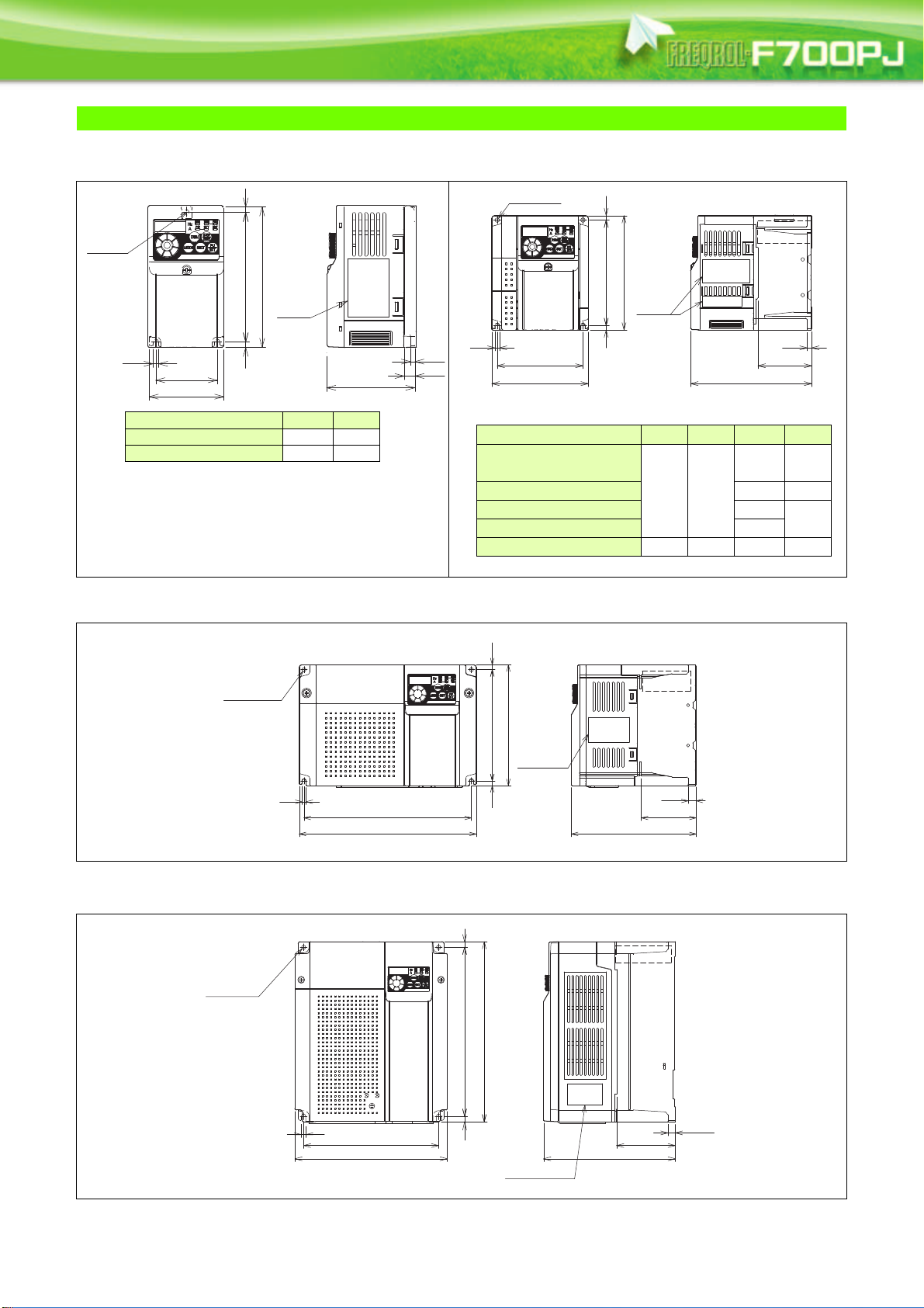
Outline Dimension Drawings
φ5 hole
5
68
56
5 118 5
128
Rating
plate
D
4
D1
Inverter Model D D1
FR-F720PJ-0.4K 112.5 42
FR-F720PJ-0.75K 132.5 62
2-φ5 hole
Rating
plate
FAN
5
W1
W
5 5
128
118
5
∗
D1
D
FR-F740PJ-0.4K and 0.75K are not provided with the cooling
fan.
Inverter Model W W1 D D1
FR-F720PJ-1.5K, 2.2K
FR-F740PJ-1.5K
108 96
135.5 60
FR-F740PJ-0.4K, 0.75K 129.5 54
FR-F740PJ-2.2K 155.5
60
FR-F740PJ-3.7K 165.5
FR-F720PJ-3.7K 170 158 142.5 66.5
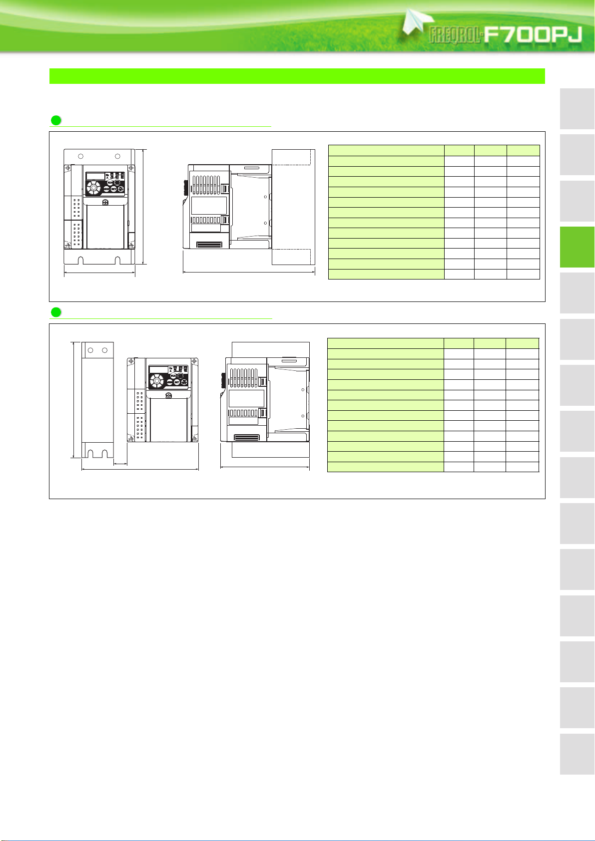
61386
150
208
5
220
2-φ5 hole
10
68
155
FAN
Rating
plate
Without a Filterpack
FR-F720PJ-0.4K, 0.75K
(Unit: mm)
FR-F720PJ-1.5K to 3.7K
FR-F740PJ-0.4K to 3.7K
FR-F720PJ-5.5K, 7.5K
FR-F740PJ-5.5K, 7.5K
FR-F720PJ-11K, 15K
FR-F740PJ-11K, 15K
2-φ6 hole
(Unit: mm)
(Unit: mm)
8
FAN
14
6
244
260
195
220
8
Rating plate
84.5
190
10.5
(Unit: mm)
FeaturesOptionsPrecautionsMotor
Connection
example
Standard
specs.
Outline
dimensions
Parameter
list
Parameter
descriptions
Protective
functions
IPM motor
control
CompatibilityWarranty
Terminal connection
diagrams
Terminal specs.
Operation panel
Parameter unit
FR Configurator
Filterpack
D
W
H
Inverter Model W H D
FR-F720PJ-0.4KF 68 218 172.5
FR-F720PJ-0.75KF 68 218 192.5
FR-F720PJ-1.5KF, 2.2KF 108 188 215.5
FR-F720PJ-3.7KF 170 188 207.5
FR-F720PJ-5.5KF, 7.5KF 220 210 230
FR-F720PJ-11KF, 15KF 220 320 275
FR-F740PJ-0.4KF, 0.75KF 108 188 184.5
FR-F740PJ-1.5KF 108 188 215.5
FR-F740PJ-2.2KF 108 188 235.5
FR-F740PJ-3.7KF 108 188 245.5
FR-F740PJ-5.5KF, 7.5KF 220 210 230
FR-F740PJ-11KF, 15KF 220 320 275
Inverter Model W H D
FR-F720PJ-0.4KF 138 218 112.5
FR-F720PJ-0.75KF 138 218 132.5
FR-F720PJ-1.5KF, 2.2KF 198 188 135.5
FR-F720PJ-3.7KF 245 188 170
FR-F720PJ-5.5KF, 7.5KF 305 210 195
FR-F720PJ-11KF, 15KF 315 320 195
FR-F740PJ-0.4KF, 0.75KF 173 188 129.5
FR-F740PJ-1.5KF 198 188 135.5
FR-F740PJ-2.2KF 198 188 155.5
FR-F740PJ-3.7KF 198 188 165.5
FR-F740PJ-5.5KF, 7.5KF 305 210 195
FR-F740PJ-11KF, 15KF 315 320 195
The clearance between the inverter and the filter is 10mm.
With a Filterpack
A Filterpack can be installed on the side or rear panel of the inverter.
This is a sample outline dimension drawing. The shape differs by the model.
Filterpack installed on the rear panel
Filterpack installed on the side panel
Filterpack
H
10
W
D
(Unit: mm)
(Unit: mm)
15
Filterpack
Capacity W W1 W2 H H1 D D1 D2 L L1
200V
0.4K, 0.75K
68 30 19 218 208 60 30 15 240 220
1.5K, 2.2K 108 55 26.5 188 178 80 55 12.5 200 220
3.7K 170 120 25 188 178 65 40 12.5 220 240
400V
H0.4K, H0.75K
108 55 26.5 188 178 55 30 12.5 200 220
H1.5K to H3.7K
108 55 26.5 188 178 80 55 12.5 200 220
The 400V class H0.4K and H0.75K have no slit.
D
12.5
C1
C1
12.5
D1
H1
H
145
195
220
H2
25
(25)
25
H2
L-bracket for rear
panel installation of
the inverter
(enclosed)
2-φC hole
2-φC hole
Rating
plate
H1
H2
H2
(GND)
(R)
(S)
(P1)
(P)
(T)
Crimping terminal φC2
L2
L
310
2.3
2.3
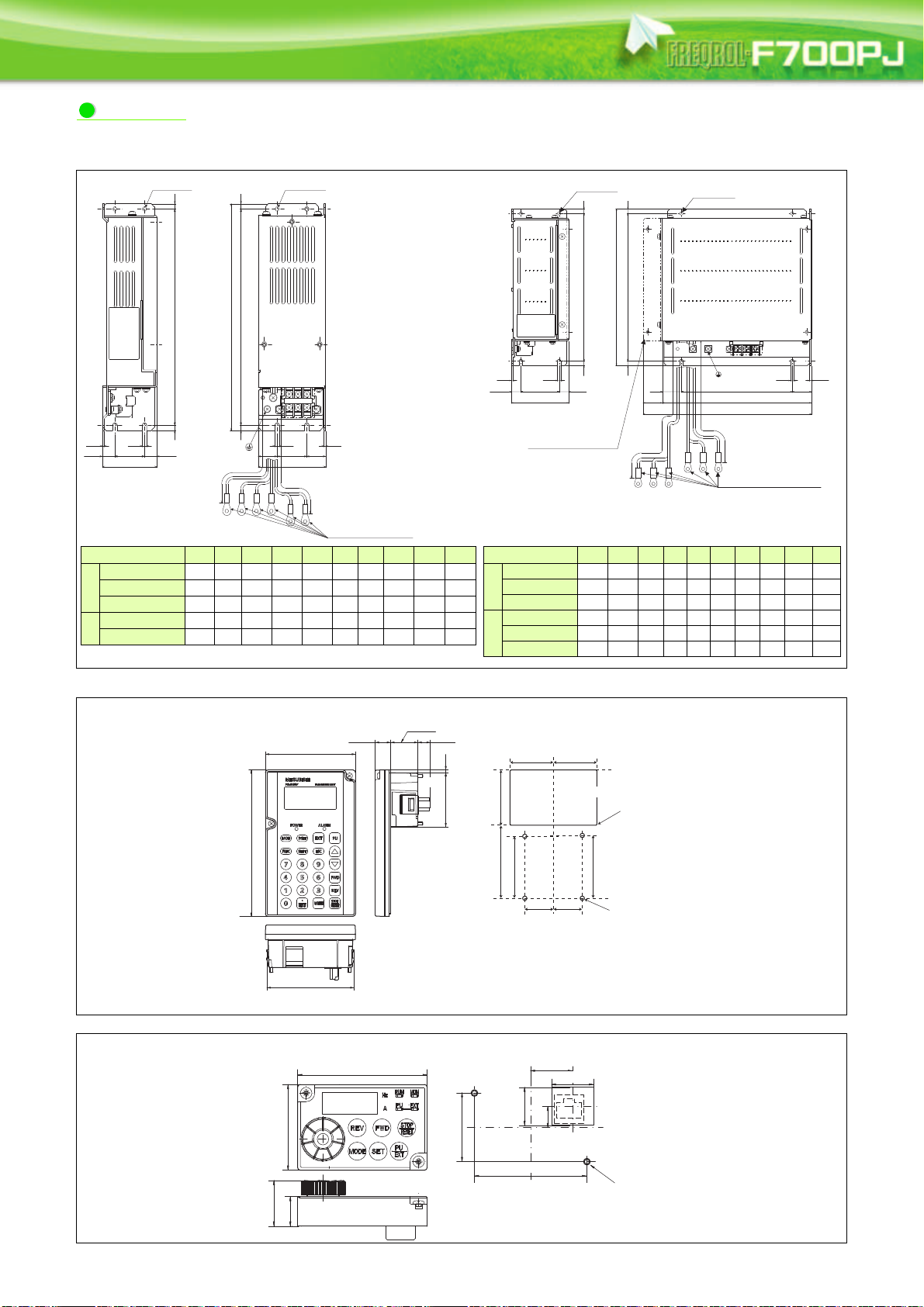
Capacity H H1 H2 D D1 C C1 C2 L L2
200V
5.5K, 7.5K
210 198 6 75 50 4.5 4.5 5.3 270 400
11K
320 305 7.5 85 60 6 6 5.3 280 280
15K
320 305 7.5 85 60 6 6 6.4 260 260
400V
H5.5K, H7.5K
210 198 6 75 50 4.5 4.5 4.3 270 400
H11K
320 305 7.5 85 60 6 6 4.3 280 280
H15K
320 305 7.5 85 60 6 6 6.4 260 260
For rear panel installation, an L-bracket is required. The L-bracket
is enclosed, but not installed to the inverter at the factory.
5
D1
D
4.5
D2 D2
H15 5
W1WW2
4.5
W2
H
H1 5
2-φ4.5 hole
2-φ4.5 hole
Rating
plate
1.6
L1
Crimping terminal φ4.3
L
1.6
(GND) (R) (S) (P1) (P)(T)
(Unit mm)
(Unit mm)
4-φ4 hole
(
Effective depth of the
installation screw hole 5.0)
M3 screw
∗2
80.3
(14.2)
2.5
50
(11.45)
25.05
135
83
∗1
∗1
∗1
∗1
67
51
40
56.8
57.8
26.5
4-R1
26.5
40
Air-bleeding
hole
When installing the FR-PU07 on the enclosure, etc., remove screws or fix the
screws to the FR-PU07 with M3 nuts.
Select the installation screw whose length will not exceed the effective depth of the
installation screw hole.
(Unit: mm)
2-M3 screw
68
45
59
36
22
22
11
20
(15.5)
24
(Unit: mm)
FR-BFP2-0.4K, 0.75K, 1.5K, 2.2K, 3.7K FR-BFP2-5.5K, 7.5K, 11K, 15K
FR-BFP2-H0.4K, H0.75K, H1.5K, H2.2K, H3.7K FR-BFP2-H5.5K, H7.5K, H11K, H15K
Parameter unit (option) (FR-PU07)
<Outline drawing> <Enclosure cut dimension drawing>
Enclosure surface operation panel (option) (FR-PA07)
16
<Outline drawing> <Enclosure cut dimension drawing>
FeaturesOptionsPrecautionsMotor
Connection
example
Standard
specs.
Outline
dimensions
Parameter
list
Parameter
descriptions
Protective
functions
IPM motor
control
CompatibilityWarranty
Terminal connection
diagrams
Terminal specs.
Operation panel
Parameter unit
FR Configurator
Terminal Connection Diagram
Earth
(Ground)
Motor
M
Earth (Ground)
Three-phase
AC power
supply
MCCB MC
R/L1
P1 P/+
PR
N/-
S/L2
T/L3
U
V
W
Earth
(Ground)
Forward
rotation
start
Reverse
rotation
start
Middle
speed
High
speed
Terminal 4
input
selection
Control input signals (No voltage input allowed)
24VDC power supply
(Common for external power supply transistor)
STR
STF
RH
RM
AU
SD
PC
Relay output
Relay output
(Fault output)
Running
Open collector output
Open collector output common
Sink/source common
RUN
SE
A
B
C
FM
SD
Indicator
(Frequency meter, etc.)
-
Moving-coil type
1mA full-scale
Calibration resistor
Frequency setting signals (Analog)
2 0 to 5VDC
10(+5V)
2
3
1
4 4 to 20mADC
Frequency
setting
potentiometer
1/2W1kΩ
Terminal 4
input
(Current input)
(+)
(-)
5(Analog common)
∗5 It is recommended to use
2W1k
Ω
when the
frequency setting signal
is changed frequently.
∗5
∗4 Terminal input specifications
can be changed by analog
input specifications
switchover (Pr. 73).
Terminal 10 and terminal 2
are used as PTC input
terminal (Pr. 561).
∗3 When using terminals
PC-SD as a 24VDC
power supply, take care
not to short across
terminals PC and SD.
PU
connector
∗8 It is not necessary when
calibrating the indicator from
the operation panel.
∗2 DC reactor (FR-HEL)
When connecting a DC reactor, remove the
jumper across P1 and P/+.
Control circuit terminal
Main circuit terminal
Sink logic
Jumper
∗2
∗7
∗3
∗4
∗6
∗8
The function of these
terminals can be changed to
the reset signal, etc. with the
input terminal assignment
(Pr. 178 to Pr. 182)
.
Multi-speed
Terminal functions vary by
Pr. 190 RUN terminal
function selection
Terminal functions vary by
Pr. 192 A,B,C terminal
function selection
SINK
SOURCE
VI
∗6
0 to 5VDC
(0 to 10VDC)
0 to 10VDC
∗6 Terminal input specifications can be changed by analog
input specifications switchover (Pr. 267). Set the
voltage/current input switch in the "V" position to select
voltage input (0 to 5V/0 to10V) and "I" (initial value) to
select current input (4 to 20mA).
To use terminal 4 (initial setting is current input), set "4"
in any of Pr.178 to Pr.182 (input terminal function selection)
to assign the function, and turn ON AU signal.
Brake unit
(Option)
Voltage/current
input switch
Main circuit
Control circuit
R
Contact input common
With Filterpack
Three-phase
AC power
supply
MCCB MC
R/L1
P1
P/+
S/L2
T/L3
Earth (ground)
∗1 Remove the jumper
across the terminals
P1 and P/+ to install
Filterpack.
Jumper
∗1
R0
S0
T0
P1
P
Filterpack
FR-BFP2
Inverter
GND
R
S
T
∗9
∗9 Operation and parameter setting can be done
from the parameter unit (FR-PU07) and the
enclosure surface operation panel (FRPA07).
(Use the option cable (FR-CB2 ).)
RS-485 communication can be utilized from
a personal computer and other devices.
+
24V
Inrush current
limit circuit
∗7
Brake resistor (FR-ABR, MRS type, MYS type)
Install a thermal relay to prevent an overheat
and burnout of the brake resistor.
Always install a thermal relay when using a
brake resistor whose capacity is 11K or higher.
NOTE
To prevent a malfunction caused by noise, separate the signal cables more than 10cm from the power cables. Also
separate the main circuit wire of the input side and the output side.
After wiring, wire offcuts must not be left in the inverter.
Wire offcuts can cause an alarm, failure or malfunction. Always keep the inverter clean. When drilling mounting holes
in an enclosure etc., take care not to allow chips and other foreign matter to enter the inverter.
The terminals S1, S2, SC, and SO are for manufacturer setting. Do not remove the shortening wires across the
terminals S1 and SC and the terminals S2 and SC.
17
Terminal Specification Explanation
Typ e
Inverter
Main circuit
Filterpack
Contact input
Control circuit/Input signal
Frequency setting
Thermistor
Ter minal
Symbol
R/L1, S/L2,
T/L3
Ter minal Name Terminal Specification
AC power input
U, V, W Inverter output
P/+, PR Brake resistor connection
P/+, N/- Brake unit connection
P/+, P1
DC reactor (Filterpack)
connection
Earth (Ground)
R0, S0, T0
Commercial power
supply input
Earth (Ground)
R, S, T Inverter power supply
P, P1 DC reactor terminal
GND
Inverter earth (ground)
connection
STF Forward rotation start
STR Reverse rotation start
RH, RM Multi-speed selection
AU Terminal 4 input selection
Contact input common
(sink) (initial setting)
SD
External transistor
common (source)
24VDC power supply
common
External transistor
common (sink)
PC
(initial setting)
Contact input common
(source)
24VDC power supply
10
2
4
5
Frequency setting power
supply
Frequency setting
(voltage)
Frequency setting
(current)
Frequency setting
common
10
PTC thermistor input
2
Connect to the commercial power supply.
Do not connect anything to these terminals when using the high power factor converter (FRHC2) or power regeneration common converter (FR-CV).
To use Filterpack, connect the R, S, and T cables of Filterpack.
Connect a three-phase squirrel-cage motor or a dedicated IPM motor.
Connect a brake resistor (FR-ABR, MRS type, MYS type) across terminals P/+ and PR.
Connect the brake unit (FR-BU2), power regeneration common converter (FR-CV) or high
power factor converter (FR-HC2).
Remove the jumper across terminals P/+ and P1 and connect a DC reactor.
To use Filterpack, remove the jumper across the terminals P/+ and P1, then connect the P and
P1 cables of Filterpack.
For earthing (grounding) the inverter chassis. Must be earthed (grounded).
To use Filterpack, connect the GND cable of Filterpack.
Connect to the commercial power supply.
For earthing (grounding) the Filterpack. Must be earthed (grounded).
Connect to R/L1, S/L2, and T/L3 of the inverter.
Remove the jumper across terminals
Connect to the earth (ground) terminal of the inverter.
Turn ON the STF signal to start forward rotation and turn it
OFF to stop.
Turn ON the STR signal to start reverse rotation and turn it
OFF to stop.
Multi-speed can be selected according to the combination of RH and RM signals.
The terminal 4 function is available only when the AU signal is ON. (the operation with the
frequency setting signal of 4 to 20mA DC is available)
Turning ON the AU signal disables the terminal 2 (voltage input) function.
Common terminal for contact input terminal (sink logic) and terminal FM.
Connect this terminal to the power supply common terminal of a transistor output (open
collector output) device, such as a programmable controller, in the source logic to avoid
malfunction by undesirable current.
Common output terminal for 24VDC 0.1A power supply (PC terminal).
Isolated from terminals 5 and SE.
Connect this terminal to the power supply common terminal of a transistor output (open
collector output) device, such as a programmable controller, in the sink logic to avoid
malfunction by undesirable current.
Common terminal for contact input terminal (source logic).
Can be used as 24VDC 0.1A power supply.
Used as power supply when connecting potentiometer for
frequency setting (speed setting) from outside of the inverter.
Inputting 0 to 5VDC (or 0 to 10V) provides the maximum
output frequency at 5V (10V) and makes input and output
proportional. Use Pr. 73 to switch between input 0 to 5VDC
input (initial setting) and 0 to 10VDC.
Inputting 4 to 20mADC (or 0 to 5V, 0 to 10V) provides the
maximum output frequency at 20mA and makes input and
output proportional. The input signal to terminal 4 is valid
only when the AU signal is ON (terminal 2 input is invalid).
Use Pr. 267 to switch from among input 4 to 20mA (initial
setting), 0 to 5VDC and 0 to 10VDC. Set the voltage/current
input switch in the "V" position to select voltage input (0 to
5V/0 to 10V).
Frequency setting signal (terminal 2 or 4) common terminal. Do not earth (ground).
For connecting PTC thermistor output.
When PTC thermistor protection is valid (Pr. 561 "9999"),
terminal 2 is not available for frequency setting.
P/+
and P1, and connect to the terminals
When the STF and STR signals
are turned ON simultaneously,
the stop command is given.
5VDC
permissible load current 10mA
Input resistance10k1k
Permissible maximum voltage
20VDC
Current input:
Input resistance 2495
Maximum permissible current
30mA
Voltage input:
Input resistance10k 1k
Permissible maximum voltage
20VDC
Adaptive PTC thermistor
specification
Heat detection resistance :
500 to 30k (Set by Pr. 561)
P/+
and P1 of the inverter.
18
FeaturesOptionsPrecautionsMotor
Connection
example
Standard
specs.
Outline
dimensions
Parameter
list
Parameter
descriptions
Protective
functions
IPM motor
control
CompatibilityWarranty
Terminal connection
diagrams
Terminal specs.
Operation panel
Parameter unit
FR Configurator
Typ e
Relay
Open collector
Control circuit terminal/Output signal
Pulse
Communication
Ter minal
Symbol
Ter minal Name Terminal Specification
1 changeover contact output indicates that the inverter protective function has activated and
the output stopped.
Fault: discontinuity across B-C (continuity across A-C),
Normal: continuity across B-C (discontinuity across A-C)
A, B, C
Relay output
(fault output)
Contact capacity:230VAC 0.3A (power factor =0.4) 30VDC 0.3A
Switched Low when the inverter output frequency is equal to
RUN Inverter running
or higher than the starting frequency (initial value 0.5Hz).
Switched High during stop or DC injection brake operation.
(Low is when the open collector output transistor is ON
(conducts). High is when the transistor is OFF (does not
Permissible load 24VDC
(maximum 27VDC) 0.1A
(a voltage drop is 3.4V maximum
when the signal is ON)
conduct).)
SE
Open collector output
common
Common terminal of terminal RUN.
Selected one e.g. output frequency from monitored items.
FM For meter
(Not output during inverter reset.)
The output signal is proportional to the magnitude of the
Permissible load current 1mA
1440 pulses/s at full scale
corresponding monitored item.
With the PU connector, communication can be established through RS-485.
Conforming standard: EIA-485 (RS-485)
— PU connector
Transmission format: Multidrop link
Communication speed: 4800 to 38400bps
Overall length: 500m
NOTE
To change the input specification for terminal 4, set Pr. 267 and the voltage/current input switch correctly, then input
the analog signal relevant to the setting. Applying a voltage with voltage/current input switch in "I" position (current
input is selected) or a current with switch in "V" position (voltage input is selected) could cause component damage
of the inverter or analog circuit of output devices.
Connecting the power supply to the inverter output terminals (U, V, W) will damage the inverter. Do not perform such
wiring.
indicates that terminal functions can be selected using Pr. 178 to Pr. 182, Pr. 190 and Pr. 192 (I/O terminal function
selection).
The terminal names and functions shown here are the initial settings.
The terminals S1, S2, SC, and SO are for manufacturer setting. Do not connect anything to these.
Doing so may cause an inverter failure. Do not remove the shortening wires across the terminals S1 and SC and the
terminals S2 and SC. Removing either shortening wire disables the inverter operation.
19
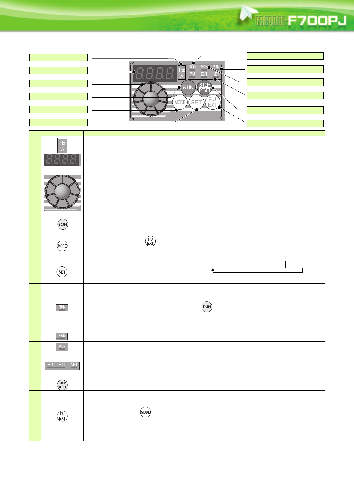
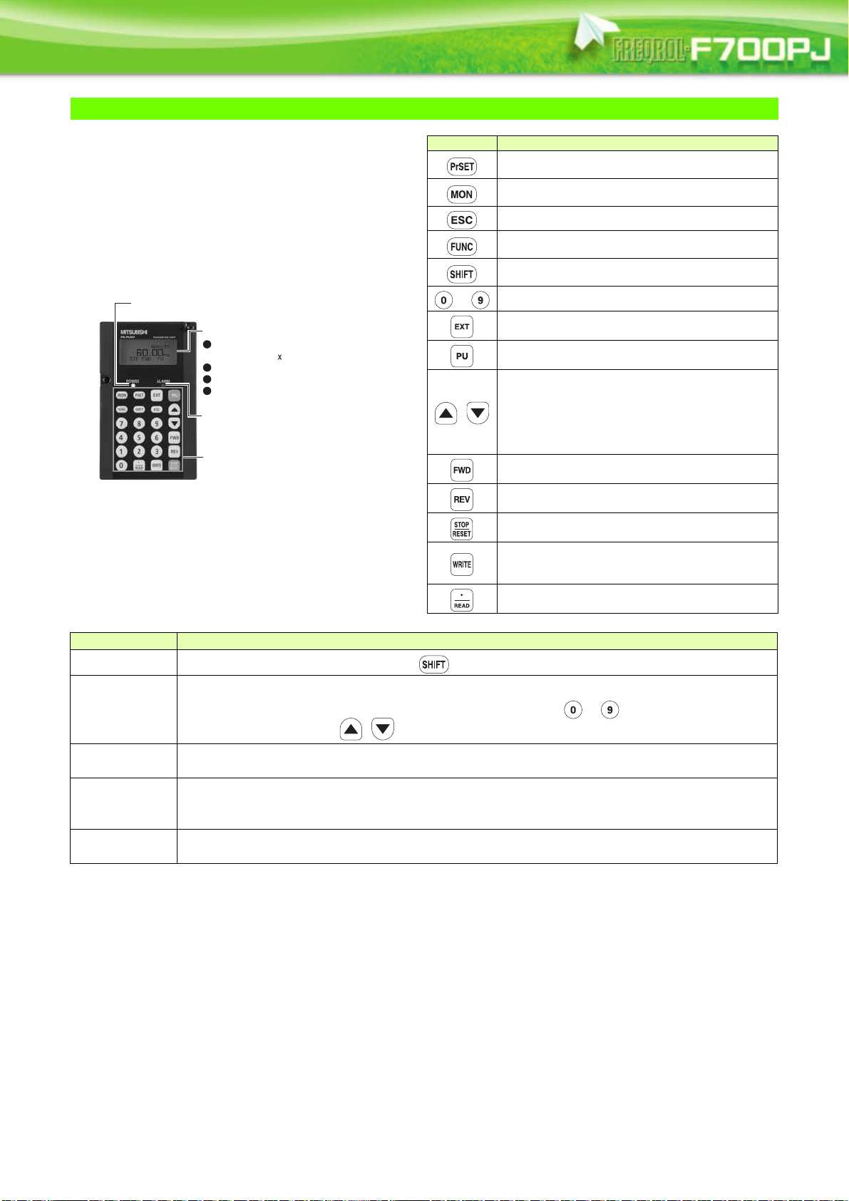
Explanation of the Operation Panel
(a) Unit indicator
(b) Monitor (4-digit LED)
(c) Setting dial
(d) Start command
(e) MODE key
(f) SET key
(g) Operation status indicator
(h)
Parameter setting mode indicator
(i) Monitor indicator
(j) Operation mode indicator
(k) STOP/RESET key
(l) PU/EXT key
Output frequency
Output current
Output voltage
*
Energy saving monitor is displayed when the
energy saving monitor is set with Pr. 52.
The operation panel cannot be removed from the inverter.
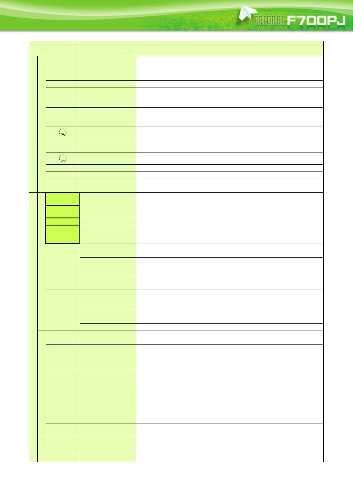
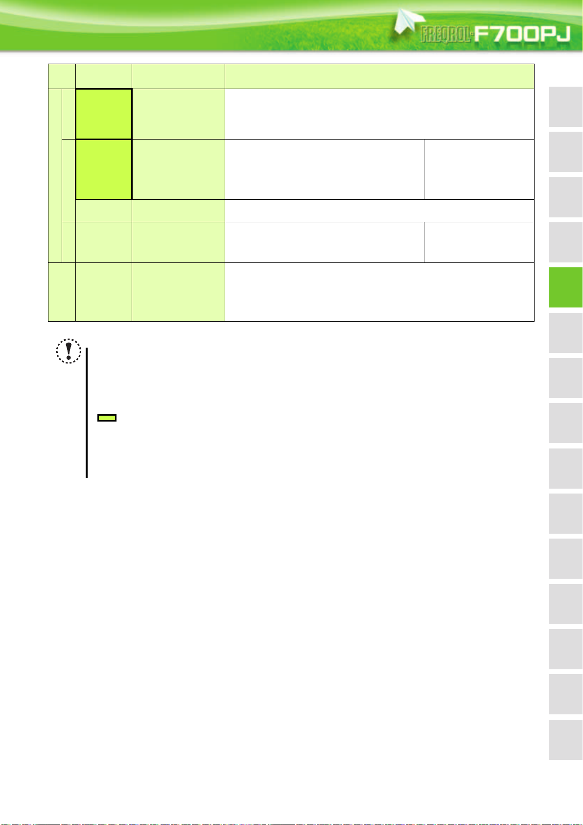
No. Component Name Description
(a)
(b)
(c)
(d)
(e)
(f)
(g)
(h)
(i)
(j)
(k)
(l)
Unit indicator
Monitor (4-digit
LED)
Setting dial
Start command Select the rotation direction in Pr. 40.
MODE key
SET key
Operation status
indicator
Parameter setting
mode indicator
Monitor indicator Lit to indicate the monitor mode.
Operation mode
indicator
STOP/RESET
key
PU/EXT key
Hz: Lit to indicate frequency. (Flickers when the set frequency monitor is displayed.)
A: Lit to indicate current.
(Both "Hz" and "A" turns OFF to indicate a value other than frequency or current. )
Shows the frequency, parameter number, etc.
(To monitor the output power, the set frequency and other items, set Pr. 52.)
The dial of the Mitsubishi inverters. The setting dial is used to change the frequency and
parameter settings.
Press the setting dial to perform the following operations:
To display a control method (general-purpose motor control or IPM motor control) during the
monitor mode
To display the set frequency when pressed for 1s or longer under PU operation mode or External/
PU combined operation mode (Pr. 79 = "3")
To display the present setting during calibration
To display a fault history number in the faults history mode
Used to switch among different setting modes.
Pressing simultaneously changes the operation mode.
Holding this key for 2 seconds locks the operation. The key lock is invalid when Pr. 161 = "0
(initial setting)."
Used to enter a setting.
If pressed during the operation,
monitored item changes as the
following:
Lit or flickers during inverter operation.
* Lit: When the forward rotation operation is being performed.
Slow flickering (1.4s cycle): When the reverse rotation operation is being performed.
Fast flickering (0.2s cycle): When has been pressed or the start command has been
given, but the operation cannot be made.
When the frequency command is less than the starting frequency.
When the MRS signal is being input.
Lit to indicate the parameter setting mode.
PU: Lit to indicate the PU operation mode.
EXT: Lit to indicate the External operation mode.(EXT is lit at power-ON in the initial setting.)
NET: Lit to indicate the Network operation mode.
PU and EXT: Lit to indicate EXT/PU combined operation mode 1 and 2
All of these indicators are OFF when the command source is not at the operation panel.
Used to stop operation commands.
Used to reset a fault when the protective function (fault) is activated.
Used to switch between the PU and External operation modes.
To use the External operation mode (operation using a separately connected frequency setting
potentiometer and start signal), press this key to light up the EXT indicator.
(Press simultaneously (0.5s), or change the Pr .79 setting to change to the combined
operation mode. )
PU: PU operation mode
EXT: External operation mode
Used to cancel the PU stop also.
*
20
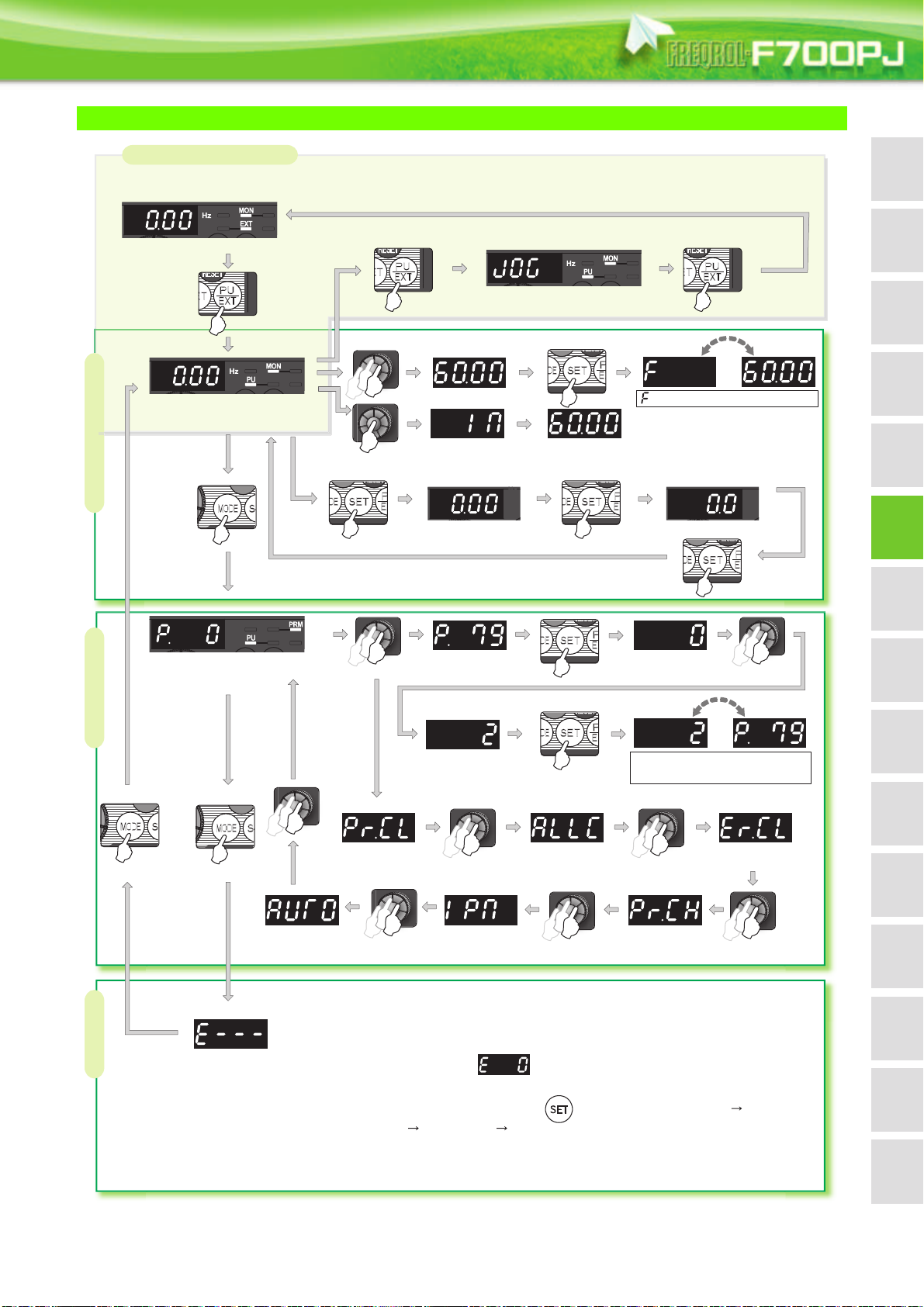
Basic Operation of the Operation Panel
Hz
A
STOP
Operation mode switchover
Parameter settingFaults history Monitor/frequency setting
At power-ON (External operation mode)
PU operation mode
(output frequency monitor)
Parameter setting mode
PU Jog operation mode
Output current monitor
General-purpose
motor control
Set frequency
is displayed
Output voltage monitor
Display the
present setting
Value change
Keep pressing
the setting dial
Parameter write is completed!!
Parameter and a setting value
flicker alternately.
Parameter clear
Automatic
parameter setting
IPM parameter
initialization
All parameter
clear
Faults history clear
Initial value
change list
(Example)
(Example)
(After 1s)
Frequency setting has been
written and completed!!
and frequency flicker alternately.
[Operation for displaying faults history]
The past eight faults can be displayed using the setting dial.
(The latest fault is ended by ".".)
When no fault history exists, is displayed.
While a fault is displayed:
The display shifts as follows by pressing : Output frequency at the fault
Output current Output voltage Energization time.
(After Energization time, it goes back to a fault display.)
Pressing the setting dial shows the fault history number.
Value change
FeaturesOptionsPrecautionsMotor
example
Connection
specs.
Standard
Outline
dimensions
diagrams
Terminal connection
Terminal specs.
Parameter unit
FR Configurator
Operation panel
list
Parameter
Parameter
descriptions
21
functions
Protective
control
IPM motor
CompatibilityWarranty
Explanations of Parameter unit
FR-PU07
Parameter unit (FR-PU07)
The parameter unit is a convenient tool for inverter setting
such as direct input method with a numeric keypad,
operation status indication, and help function.
Eight languages can be displayed.
Parameter setting values of maximum of three inverters can
be stored.
The parameter unit connection cable FR-CB20 is required for connecting to
the inverter.
POWER lamp
Lit when the power turns on.
Monitor
Liquid crystal display
(16 characters 4 lines with backlight)
Interactive parameter setting
Trouble shooting guidance
Monitor (frequency, current, power, etc.)
ALARM lamp
Lit to indicate an inverter alarm occurrence.
Operation keys
(Refer to the table on the right)
Main functions
Function Description
Monitor
6 types of monitors appear by simply pressing .
Key Description
Use for parameter setting
Press to choose the parameter setting mode.
First priority monitor is displayed.
In the initial setting, the output frequency is displayed.
Operation cancel key
Used to display the function menu.
A variety of functions can be used on the function menu.
Used to shift to the next item in the setting or monitoring
mode.
to
Used to enter a frequency, parameter number or set value.
Inverter operates in the External operation mode.
Used to select the PU operation mode to display the
frequency setting screen.
Used to keep on increasing or decreasing the running
frequency. Hold down to vary the frequency.
Press either of these keys on the parameter setting mode
screen to change the parameter setting value sequentially.
On the selecting screen, these keys are used to move the
cursor.
Forward rotation command key.
Reverse rotation command key.
Stop command key.
Used to reset the inverter when an alarm occurs.
Used to write a set value in the setting mode.
Used as a clear key in the all parameter clear or alarm
history clear mode.
Used as a decimal point when entering numerical value.
Press to read the item selected with the cursor.
For PU operation mode and External/PU combined operation mode (Pr.79 = "3"), frequency setting is available.
Frequency setting
Settings is performed by the direct setting, which sets frequency directly by to , and the step setting, which
sets frequency continuously by .
Parameter Setting
Reading parameter and changing setting values are easily done. To change the setting value of an parameter, specify
the parameter number, or select a parameter from the functional parameter list.
FR-PU07 (PU07BB) reads parameter settings of an inverter, and stores three different parameter settings.
Batch copy
FR-PU07 (PU07BB) can also copy the stored parameter setting to another inverter of the same series, or verify its
stored parameter setting against the parameter setting stored in an inverter.
Operation
Available function differs by the inverter. Please refer to the instruction manual of the inverter and the parameter unit
Switching between External operation mode [EXT] and PU operation mode [PU] is easy.
Start/stop is enabled during PU operation mode and External/PU operation mode (Pr.79 = "3").
22
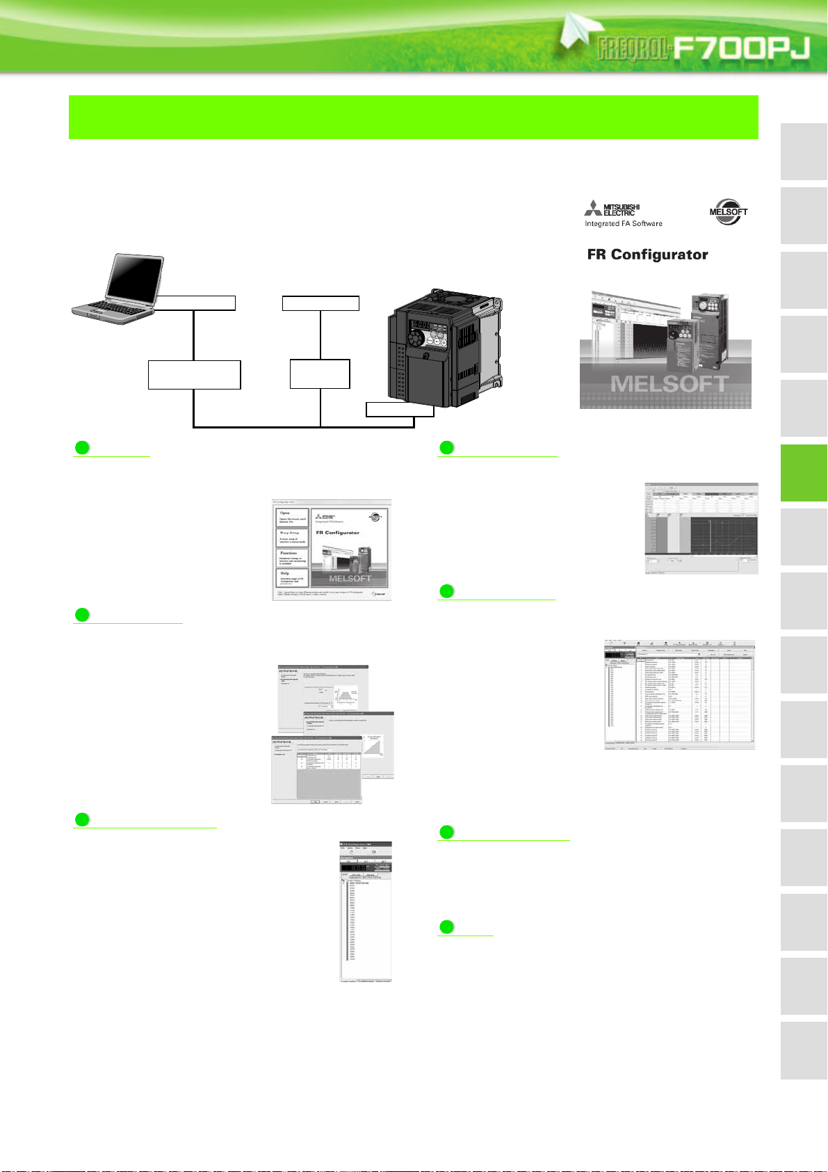
FR Configurator (INVERTER SETUP SOFTWARE)
(Windows® 2000 Professional SP4 or later, Windows® XP Home Edition SP2 or later,
FR-SW3-SETUP-WE
®
Windows
FR Configurator is software that offers an easy operating environment.
Can be utilized effectively from inverter setting up to maintenance.
Parameter setting, monitoring, etc. can be performed on a display of Windows personal
computer.
RS-485 communication is available to connect a personal computer to an inverter using
a PU connector.
An RS-485-to-RS-232C or USB-to-RS-485 converter is required separately.
Serial port
Personal computer
(FR Configurator)
RS-232C/RS-485
Serial cable
converter
Startup
Desired function can be performed just after a start-up of the
software.
(1) Open the recent used System
File
(2) Perform Easy Setup
(3) Perform each function
(4) Help
XP Professional SP2 or later, Windows Vista® SP1 or later, Windows® 7 supported)
Inverter
USB connector
or
USB cable
USB/RS-485
converter
PU connector
Monitor area
In Monitor area, inverter status can be monitored.
(1) Displays monitor data in
waveform [Graph]
(2) Monitors the status of I/O
terminals. [I/O Terminal Monitor]
(3) Displays multiple data in batch
[Batch Monitor]
FeaturesOptionsPrecautionsMotor
example
Connection
specs.
Standard
Outline
dimensions
diagrams
Terminal connection
Terminal specs.
Parameter unit
FR Configurator
Operation panel
list
Parameter
Easy Setup
From station number to parameter setting, setting with
wizard style dialog (interactive) is available.
Procedure for Easy Setup
(1) System File setting
(2) Communication setting
(3) Inverter recognition
(4) Control method selection
(5) Motor setting
(6) Start command, frequency
command setting
(7) Parameter setting
Navigation area
In Navigation area, switching ONLINE/ OFFLINE
and changing operation mode can be performed.
(1) Frequency setting and forward/reverse
rotation [Test operation]
(2) Display the connected inverter in tree view
[System List]
(3) Function setting without regard to
parameter number [Basic setting]
(4) Estimates the cause of trouble, and
suggests counteraction. [Troubleshooting]
System area
In System area, parameter setting, Diagnosis,
Troubleshooting, etc. can be performed.
(1) Parameter reading,
writing, verification,
Functional List and
Individual List display are
available.
[Parameter List]
(2) Displays alarm history
and monitor value at
each alarm occurrence.
[Diagnosis]
Parameter setting conversion from conventional models
(3)
[Convert]
Setting wizard
Setting wizard can set parameters with wizard style dialog
(interactive). Inputting or selecting required items for each
function, parameter setting can be made, without regard to
parameter number.
Help
Displays operating instructions and details of each
parameters.
Parameter
descriptions
functions
Protective
control
IPM motor
FR-SW3-SETUP-WE is available for download (free of charge) from the below URL on the internet. FR Configurator SW3 (FR-SW3-SETUPWE or FR-SW1-SETUP-WE) needs to be installed to the personal computer prior to updating the software. Also, user registration is required
for the download (free of charge.) (Registration is free of charge.)
Homepage address www.MitsubishiElectric.co.jp/fa
FR-SW3-SETUP-WE (for 700 series) and FR-SW1-SETUP-WE (500 series) can be installed from the FR Configurator SW3.
CompatibilityWarranty
23
Parameter List
For simple variable-speed operation of the inverter, the initial setting of the parameters may be used as they are. Set the
necessary parameters to meet the load and operational specifications. Parameter setting, change and check can be made
from the operation panel. For details of parameters, refer to the instruction manual.
POINT
Only simple mode parameters are displayed by the initial setting of Pr.160 Extended function display selection. Set
Pr.160 Extended function display selection as required.
To use the inverter under IPM motor control, refer to page 81.
Pr.160 Remarks
9999
(initial value)
0 Simple mode and extended mode parameters can be displayed.
Simple mode parameter
Only the simple mode parameters can be displayed.
Parameter
Number
0 Torque boost 0.1%
1 Maximum frequency 0.01Hz 120Hz 0 to120Hz
2 Minimum frequency 0.01Hz 0Hz 0 to120Hz
3 Base frequency 0.01Hz 60Hz 0 to 400Hz
Multi-speed setting
4
(high speed)
Multi-speed setting
(middle speed)
Multi-speed setting (low
6
speed)
7 Acceleration time 0.1s 5s/15s
8 Deceleration time 0.1s 10s/30s 0 to 3600s
Electronic thermal O/L
9
relay
79
125
126
160
998
999
Operation mode
selection
Terminal 2 frequency
setting gain frequency
Terminal 4 frequency
setting gain frequency
Extended function
display selection
IPM parameter
initialization
Automatic parameter
setting
Name
Unit
0.01Hz 60Hz 0 to 400Hz
0.01Hz 30Hz 0 to 400Hz
0.01Hz 10Hz 0 to 400Hz
0.01A
10
0.01Hz 60Hz 0 to 400Hz
0.01Hz 60Hz 0 to 400Hz
1 9999 0, 9999
10
1 9999
Initial
Value
6%/4%/
3%/2%
Rated
inverter
current
0 to 30%
0 to 3600s
0 to 500A
0, 1, 2, 3, 4, 6,
7
0, 1, 12, 101,
112
10, 20, 21,
9999
Range Application
Use this parameter to increase starting
torque under V/F control. Use this when a
loaded motor cannot be driven and the
warning [OL] occurs, then the inverter trips
with [OC1] under V/F control.
Initial value depends on the inverter capacity.
(0.75K or less/1.5K to 3.7K/5.5K, 7.5K/11K, 15K)
Use this parameter to set the upper limit for
the output frequency.
Use this parameter to set the lower limit for
the output frequency.
Use this parameter when the rated motor
frequency is 50Hz.
Check the rating plate of the motor.
Use these parameters to change among preset operation speeds with the terminals. The
speeds are pre-set with parameters.
Use these parameters to set the
acceleration/deceleration time.
Initial value depends on the inverter capacity.
(7.5K or less/11K, 15K)
With this parameter, the inverter protects the
motor from heat.
Set the rated motor current.
Use this parameter to select the source of
start command and frequency setting.
Use this parameter to change the frequency
at the maximum potentiometer setting (5V in
the initial setting)
Use this parameter to change the frequency
at the maximum current input (20mA in the
initial setting)
Parameter which can be read from the
operation panel and parameter unit can be
restricted.
By performing IPM parameter initialization,
IPM motor control is selected and the
parameters, which are required to drive an
IPM motor, are changed.
Parameter settings are changed as a batch.
Those include communication parameter
settings for the Mitsubishi's human machine
interface (GOT) connection and the
parameter setting for the rated frequency
settings of 50Hz/60Hz.
Refer
to
page
33
33
33
335
34
34
43
46
46
47
80
56
24

FeaturesOptionsPrecautionsMotor
Connection
example
Standard
specs.
Outline
dimensions
Parameter
list
Parameter
descriptions
Protective
functions
IPM motor
control
CompatibilityWarranty
Terminal connection
diagrams
Terminal specs.
Operation panel
Parameter unit
FR Configurator
Parameter
Number
Name
Unit
Pr.CL Parameter clear 1 0 0, 1
ALLC All parameter clear 1 0 0, 1
Initial
Value
Range Application
Setting "1" returns all parameters except
calibration parameters to the initial values.
Setting "1" returns all parameters to the initial
values.
Er.CL Faults history clear 1 0 0, 1 Setting "1" clears eight past faults. 56
Pr.CH Initial value change list
IPM
IPM parameter
initialization
1 0 0, 1, 12
Displays and sets the parameters changed
from the initial value.
Use this parameter to select the IPM motor
control and to change parameter settings to
the settings required to drive an IPM motor.
Parameter settings are changed as a batch.
Those include communication parameter
AUTO
Automatic parameter
setting
settings for the Mitsubishi's human machine
interface (GOT) connection and the
parameter setting for the rated frequency
settings of 50Hz.
Refer
to
page
56
56
56
80
56
25
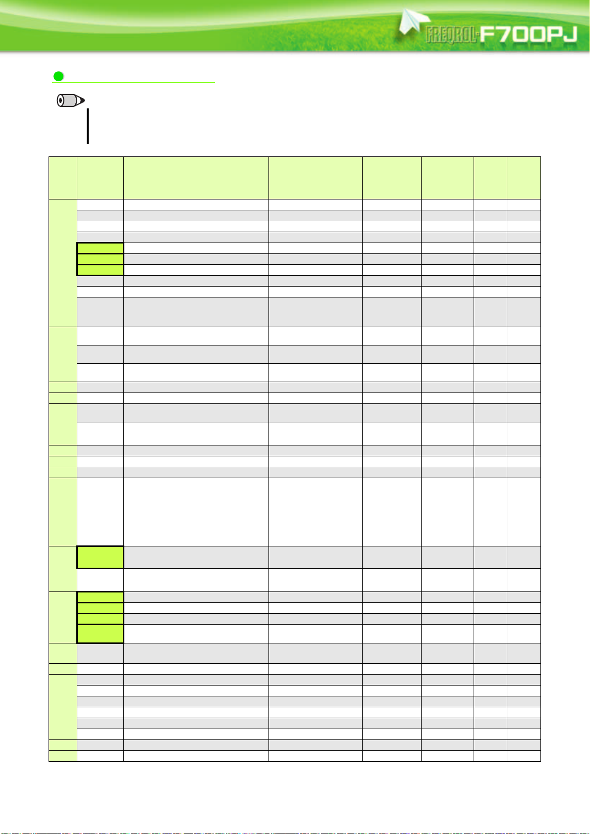
Extended mode parameter
REMARKS
The parameters marked with indicate simple mode parameters.
The shaded parameters in the table allow its setting to be changed during operation even if "0" (initial value) is set in Pr.77
Parameter write selection.
Func-
Parameter
tion
0 Torque boost 0 to 30% 0.1% 6/4/3/2% 33
1 Maximum frequency 0 to 120Hz 0.01Hz 120Hz 33
2 Minimum frequency 0 to 120Hz 0.01Hz 0Hz 33
3 Base frequency 0 to 400Hz 0.01Hz 60Hz 33
4 Multi-speed setting (high speed) 0 to 400Hz 0.01Hz 60Hz 33
5 Multi-speed setting (middle speed) 0 to 400Hz 0.01Hz 30Hz 33
6 Multi-speed setting (low speed) 0 to 400Hz 0.01Hz 10Hz 33
7 Acceleration time 0 to 3600s 0.1s 5/15s 34
Basic functions
8 Deceleration time 0 to 3600s 0.1s 10/30s 34
9 Electronic thermal O/L relay 0 to 500A 0.01A
10 DC injection brake operation frequency 0 to 120Hz 0.01Hz 3Hz 34
11 DC injection brake operation time 0 to 10s 0.1s 0.5s 34
brake
DC injection
— 13 Starting frequency 0 to 60Hz 0.01Hz 0.5Hz 34
— 14 Load pattern selection 0, 1 1 1 35
JOG
— 17 MRS input selection 0, 2, 4 1 0 35
— 18 High speed maximum frequency 120 to 400Hz 0.01Hz 120Hz 33
— 19 Base frequency voltage 0 to 1000V, 8888, 9999 0.1V 9999 33
12 DC injection brake operation voltage 0 to 30% 0.1% 4/2% 34
15 Jog frequency 0 to 400Hz 0.01Hz 5Hz 35
16 Jog acceleration/deceleration time 0 to 3600s 0.1s 0.5s 35
operation
Name Setting Range
Minimum
Setting
Increments
Initial
Val ue
Rated
inverter
current
Refer
to
Page
34
Customer
Setting
20
Acceleration/
deceleration time
22 Stall prevention operation level 0 to 150% 0.1% 120% 36
Stall
Multi-speed
— 29
— 30 Regenerative function selection 0 to 2 1 0 36,39
Frequency jump
— 37 Speed display 0, 0.01 to 9998 0.001 0 37
— 40 RUN key rotation direction selection 0, 1 1 0 37
23
prevention
24 Multi-speed setting (speed 4) 0 to 400Hz, 9999 0.01Hz 9999 33
25 Multi-speed setting (speed 5) 0 to 400Hz, 9999 0.01Hz 9999 33
26 Multi-speed setting (speed 6) 0 to 400Hz, 9999 0.01Hz 9999 33
setting
27 Multi-speed setting (speed 7) 0 to 400Hz, 9999 0.01Hz 9999 33
31 Frequency jump 1A 0 to 400Hz, 9999 0.01Hz 9999 37
32 Frequency jump 1B 0 to 400Hz, 9999 0.01Hz 9999 37
33 Frequency jump 2A 0 to 400Hz, 9999 0.01Hz 9999 37
34 Frequency jump 2B 0 to 400Hz, 9999 0.01Hz 9999 37
35 Frequency jump 3A 0 to 400Hz, 9999 0.01Hz 9999 37
36 Frequency jump 3B 0 to 400Hz, 9999 0.01Hz 9999 37
Acceleration/deceleration reference
frequency
Stall prevention operation level
compensation factor at double speed
Acceleration/deceleration pattern
selection
1 to 400Hz 0.01Hz 60Hz 34
0 to 200%, 9999 0.1% 9999 36
0 to 2 1 0 36
26
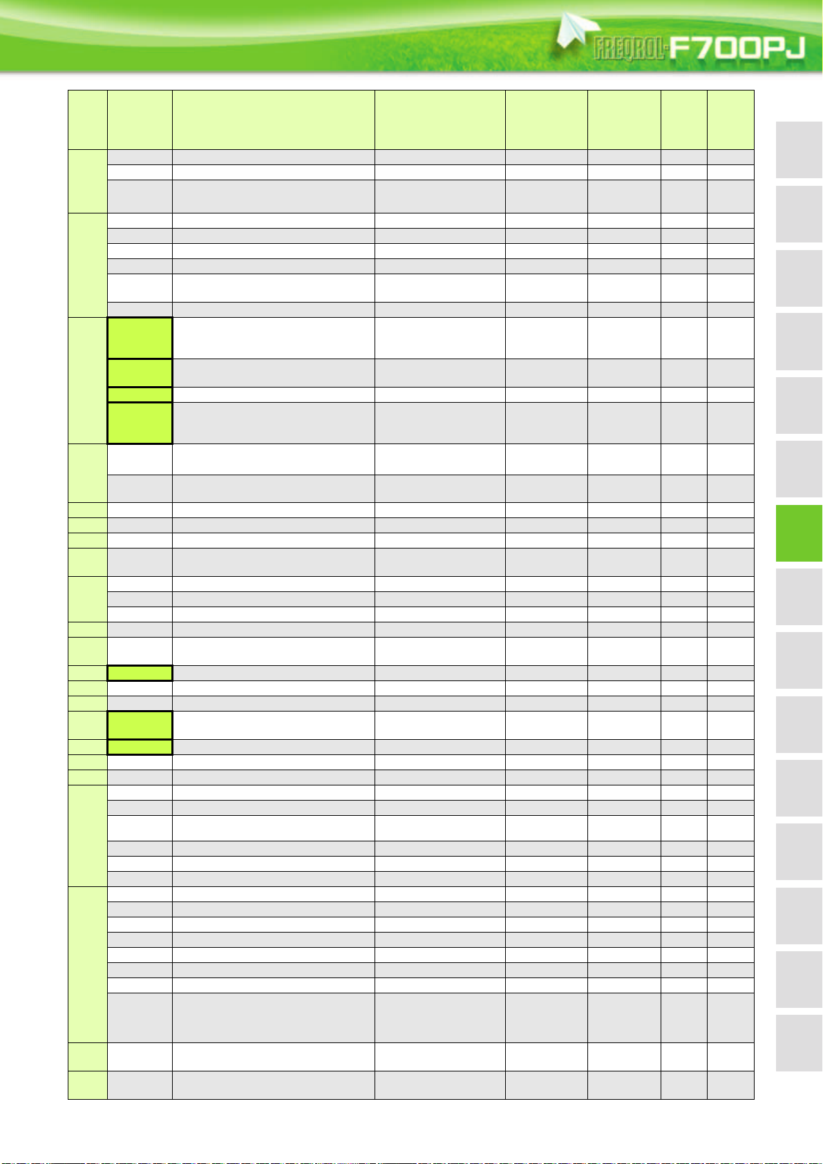
FeaturesOptionsPrecautionsMotor
Connection
example
Standard
specs.
Outline
dimensions
Parameter
list
Parameter
descriptions
Protective
functions
IPM motor
control
CompatibilityWarranty
Terminal connection
diagrams
Terminal specs.
Operation panel
Parameter unit
FR Configurator
Func-
tion
Parameter
Name Setting Range
Minimum
Setting
Increments
Initial
Val ue
41 Up-to-frequency sensitivity 0 to 100% 0.1% 10% 37
42 Output frequency detection 0 to 400Hz 0.01Hz 6Hz 37
detection
Frequency
43
Output frequency detection for reverse
rotation
0 to 400Hz, 9999 0.01Hz 9999 37
44 Second acceleration/deceleration time 0 to 3600s 0.1s 5/15s 34
45 Second deceleration time 0 to 3600s, 9999 0.1s 9999 34
46 Second torque boost 0 to 30%, 9999 0.1% 9999 33
47 Second V/F (base frequency) 0 to 400Hz, 9999 0.01Hz 9999 33
Second stall prevention operation
current
0 to 150%, 9999 0.1% 9999 36
Second functions
48
51 Second electronic thermal O/L relay 0 to 500A, 9999 0.01A 9999 34
0, 5, 8 to 12, 14, 20,
52 DU/PU main display data selection
23 to 25, 50 to 55, 61,
1038
62, 64, 100
54 FM terminal function selection
1 to 3, 5, 8 to 12, 14, 21,
24, 50, 52, 53, 61, 62
1 1 38
55 Frequency monitoring reference 0 to 400Hz 0.01Hz 60Hz 38
Monitor functions
56 Current monitoring reference 0 to 500A 0.01A
Rated
inverter
current
57 Restart coasting time 0, 0.1 to 5s, 9999 0.1s 9999 39
restart
Automatic
58 Restart cushion time 0 to 60s 0.1s 1s 39
functions
— 59 Remote function selection 0 to 3 1 0 40
— 60 Energy saving control selection 0, 9 1 0 40
— 65 Retry selection 0 to 5 1 0 41
— 66
Stall prevention operation reduction
starting frequency
0 to 400Hz 0.01Hz 60Hz 36
67 Number of retries at fault occurrence 0 to 10, 101 to 110 1 0 41
Retry
68 Retry waiting time 0.1 to 600s 0.1s 1s 41
69 Retry count display erase 0 1 0 41
— 70 Special regenerative brake duty 0 to 30% 0.1% 0% 36
— 71 Applied motor
0, 1, 3, 13, 23, 40, 43,
50, 53, 120, 210
1041,44
— 72 PWM frequency selection 0 to 15 1 1 42
— 73 Analog input selection 0, 1, 10, 11 1 1 42
— 74 Input filter time constant 0 to 8 1 1 42
— 75
Reset selection/disconnected PU
detection/PU stop selection
0 to 3, 14 to 17 1 14 43
— 77 Parameter write selection 0 to 2 1 0 43
— 78 Reverse rotation prevention selection 0 to 2 1 0 43
— 79 Operation mode selection 0 to 4, 6, 7 1 0 43
80 Motor capacity 0.4 to 15kW, 9999 0.01kW 9999 44
82 Motor excitation current 0 to 500A, 9999 0.01A 9999 45
83 Rated motor voltage 0 to 1000V 0.1V
200V/400V
84 Rated motor frequency 10 to 120Hz 0.01Hz 60Hz 45
Motor constants
90 Motor constant (R1) 0 to 50, 9999 0.001 9999 45
96 Auto tuning setting/status 0, 11, 21 1 0 45
117 PU communication station number 0 to 31 (0 to 247) 1 0 45
118 PU communication speed 48, 96, 192, 384 1 192 45
119 PU communication stop bit length 0, 1, 10, 11 1 1 45
120 PU communication parity check 0 to 2 1 2 45
121 Number of PU communication retries 0 to 10, 9999 1 1 45
122 PU communication check time interval 0, 0.1 to 999.8s, 9999 0.1s 0s 45
123 PU communication waiting time setting 0 to 150ms, 9999 1ms 9999 45
Refer
to
Page
38
45
Customer
Setting
124 PU communication CR/LF selection 0 to 2 1 1 45
PU connector communication
— 125
— 126
Terminal 2 frequency setting gain
frequency
Terminal 4 frequency setting gain
frequency
0 to 400Hz 0.01Hz 60Hz 46
0 to 400Hz 0.01Hz 60Hz 46
27

Func-
Parameter
tion
127
128 PID action selection 0, 20, 21 1 0 47
129 PID proportional band 0.1 to 1000%, 9999 0.1% 100% 47
130 PID integral time 0.1 to 3600s, 9999 0.1s 1s 47
131 PID upper limit 0 to 100%, 9999 0.1% 9999 47
132 PID lower limit 0 to 100%, 9999 0.1% 9999 47
PID operation
133 PID action set point 0 to 100%, 9999 0.01% 9999 47
134 PID differential time 0.01 to 10s, 9999 0.01s 9999 47
— 144 Speed setting switchover
145 PU display language selection 0 to 7 1 0 47
PU
— 146 Built-in potentiometer switching 0, 1 1 1 47
150 Output current detection level 0 to 150% 0.1% 120% 47
151
Current
— 154
— 156 Stall prevention operation selection 0 to 31, 100, 101 1 0 36
— 157 OL signal output timer 0 to 25s, 9999 0.1s 0s 36
— 160 Extended function display selection 0, 9999 1 9999 47
— 161
152 Zero current detection level 0 to 150% 0.1% 5% 47
detection
153 Zero current detection time 0 to 1s 0.01s 0.5s 47
PID control automatic switchover
frequency
Output current detection signal delay
time
Voltage reduction selection during stall
prevention operation
Frequency setting/key lock operation
selection
Name Setting Range
0 to 400Hz, 9999 0.01Hz 9999 47
2, 4, 6, 8, 10, 102, 104,
106, 108, 110
0 to 10s 0.1s 0s 47
1, 11 1 1 36
0, 1, 10, 11 1 0 48
Minimum
Setting
Increments
1437
Initial
Val ue
Refer
to
Page
Customer
Setting
162
functions
165
Automatic restart
166
167
Current detection
—168
— 169
170 Watt-hour meter clear 0, 10, 9999 1 9999 38
Cumulative
Input terminal function
171 Operation hour meter clear 0, 9999 1 9999 38
monitor clear
178 STF terminal function selection
179 STR terminal function selection
selection
180 AU terminal function selection
181 RM terminal function selection 1 1 48
182 RH terminal function selection 1 2 48
Automatic restart after instantaneous
power failure selection
Stall prevention operation level for
restart
Output current detection signal
retention time
Output current detection operation
selection
Parameter for manufacturer setting. Do not set.
0, 1, 10, 11 1 1 39
0 to 150% 0.1% 120% 39
0 to 10s, 9999 0.1s 0.1s 47
0, 1 1 0 47
0 to 5, 7, 8, 10, 12, 14,
16, 24, 25, 60, 62,
64 to 67, 72, 9999
0 to 5, 7, 8, 10, 12, 14,
16, 24, 25, 61, 62,
64 to 67, 72, 9999
0 to 5, 7, 8, 10, 12, 14,
16, 24, 25, 62, 64 to 67,
72, 9999
16048
1 61 48
1448
28
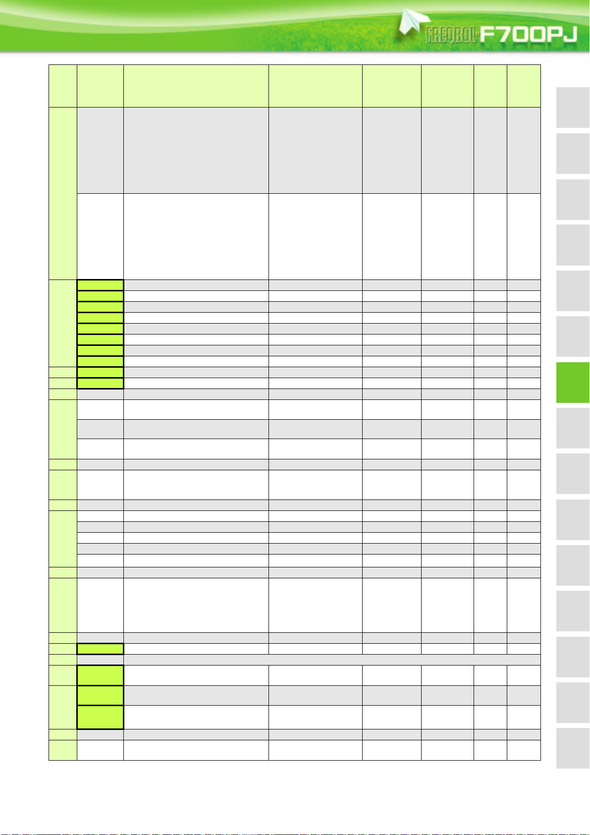
FeaturesOptionsPrecautionsMotor
Connection
example
Standard
specs.
Outline
dimensions
Parameter
list
Parameter
descriptions
Protective
functions
IPM motor
control
CompatibilityWarranty
Terminal connection
diagrams
Terminal specs.
Operation panel
Parameter unit
FR Configurator
Func-
tion
Parameter
Name Setting Range
Minimum
Setting
Increments
Initial
Val ue
0, 1, 3, 4, 7, 8, 11 to 16,
25, 26, 46 to 48, 57, 64,
70, 79, 90 to 93, 95, 96,
98 to 101, 103, 104,
190 RUN terminal function selection
107, 108, 111 to 116,
1 0 49
125, 126, 146 to 148,
157, 164, 170, 179,
190 to 193, 195, 196,
198, 199, 9999
0, 1, 3, 4, 7, 8, 11 to 16,
25, 26, 46 to 48, 57, 64,
70, 79, 90, 91, 95, 96,
98 to 101, 103, 104,
192 A,B,C terminal function selection
Output terminal function selection
107, 108, 111 to 116,
125, 126, 146 to 148,
157, 164, 170, 179, 190,
19949
191, 195, 196, 198, 199,
9999
232 Multi-speed setting (speed 8) 0 to 400Hz, 9999 0.01Hz 9999 33
233 Multi-speed setting (speed 9) 0 to 400Hz, 9999 0.01Hz 9999 33
234 Multi-speed setting (speed 10) 0 to 400Hz, 9999 0.01Hz 9999 33
235 Multi-speed setting (speed 11) 0 to 400Hz, 9999 0.01Hz 9999 33
236 Multi-speed setting (speed 12) 0 to 400Hz, 9999 0.01Hz 9999 33
237 Multi-speed setting (speed 13) 0 to 400Hz, 9999 0.01Hz 9999 33
238 Multi-speed setting (speed 14) 0 to 400Hz, 9999 0.01Hz 9999 33
Multi-speed setting
239 Multi-speed setting (speed 15) 0 to 400Hz, 9999 0.01Hz 9999 33
— 240 Soft-PWM operation selection 0, 1 1 1 42
— 241 Analog input display unit switchover 0, 1 1 0 46
— 244 Cooling fan operation selection 0, 1 1 1 49
245 Rated slip 0 to 50%, 9999 0.01% 9999 49
Slip
246 Slip compensation time constant 0.01 to 10s 0.01s 0.5s 49
compensation
247
Constant-power range slip
compensation selection
0, 9999 1 9999 49
— 249 Earth (ground) fault detection at start 0, 1 1 0 49
0 to 100s,
— 250 Stop selection
1000 to 1100s,
0.1s 9999 50
8888, 9999
— 251 Output phase loss protection selection 0, 1 1 1 50
255 Life alarm status display (0 to 15) 1 0 50
256 Inrush current limit circuit life display (0 to 100%) 1% 100% 50
257 Control circuit capacitor life display (0 to 100%) 1% 100% 50
258 Main circuit capacitor life display (0 to 100%) 1% 100% 50
259 Main circuit capacitor life measuring 0, 1 (2, 3, 8, 9) 1 0 50
Life diagnosis
— 260 PWM frequency automatic switchover 0, 1 1 1 42
Refer
to
Page
Customer
Setting
261 Power failure stop selection 0 to 2 1 0 51
stop
Power failure
— 267 Terminal 4 input selection 0 to 2 1 0 42
— 268 Monitor decimal digits selection 0, 1, 9999 1 9999 38
— 269 Parameter for manufacturer setting. Do not set.
— 295 Magnitude of frequency change setting
0, 0.01, 0.10, 1.00,
10.00
0.01 0 48
296 Password lock level 1 to 6, 101 to 106, 9999 1 9999 51
1000 to 9998 (0 to 5,
9999)
1 9999 51
Password
297 Password lock/unlock
function
— 298 Frequency search gain 0 to 32767, 9999 1 9999 45
—299
Rotation direction detection selection
at restarting
0, 1, 9999 1 0 39
29
 Loading...