

Mitsubishi FR-F720-75K, FR-F740-55K, FR-F720P-55K, FR-F720P-75K, FR-F740P-55K Instruction Manual
...
INVERTER
Plug-in option
PRE-OPERATION INSTRUCTIONS
1
FR-A7NF
INSTRUCTION MANUAL
FL remote
function
communication
INSTALLATION
WIRING
INVERTER SETTING
FL REMOTE COMMUNICATION
FUNCTION
CYCLIC TRANSMISSION
MESSAGE TRANSMISSON
DESCRIPTION AND CORRECTIVE
ACTION OF FAULT INDICATION
TROUBLESHOOTING
2
3
4
5
6
7
8
9
Thank you for choosing this Mitsubishi Inverter plug-in option.
This Instruction Manual gives handling information and
precautions for use of this equipment. Incorrect handling might
cause an unexpected fault. Before using the equipment, please
read this manual carefully to use the equipment to its optimum.
Please forward this manual to the end user.
This section is specifically about
safety matters
Do not attempt to install, operate, maintain or inspect this
product until you have read through this Instruction Manual and
appended documents carefully and can use the equipment
correctly. Do not use this product until you have a full
knowledge of the equipment, safety information and
instructions.
In this Instruction Manual, the safety instruction levels are
classified into "WARNING" and "CAUTION".
Incorrect handling may cause
WARNING
CAUTION
The level may even lead to a serious
consequence according to conditions. Both instruction levels
must be followed because these are important to personal
safety.
CAUTION
hazardous conditions, resulting in
death or severe injury.
Incorrect handling may cause
hazardous conditions, resulting in
medium or slight injury, or may cause
only material damage.
SAFETY INSTRUCTIONS
1. Electric Shock Prevention
WARNING
• While power is ON or when the inverter is running, do not
open the front cover. You may get an electric shock.
• Do not run the inverter with the front cover or wiring cover
removed. Otherwise, you may accidentally touch the exposed
high-voltage terminals and charging part and get an electric
shock.
• Even if power is OFF, do not remove the front cover except for
wiring or periodic inspection. You may accidentally touch the
charged inverter circuits and get an electric shock.
• Before wiring or inspection, power must be switched OFF. To
confirm that, LED indication of the operation panel must be
checked. (It must be OFF.) Any person who is involved in
wiring or inspection shall wait for at least 10 minutes after the
power supply has been switched OFF and check that there
are no residual voltage using a tester or the like. The
capacitor is charged with high voltage for some time after
power OFF, and it is dangerous.
• Any person who is involved in wiring or inspection of this
equipment shall be fully competent to do the work.
• The plug-in option must be installed before wiring. Otherwise,
you may get an electric shock or be injured.
• Do not touch the plug-in option or handle the cables with wet
hands. Otherwise you may get an electric shock.
• Do not subject the cables to scratches, excessive stress,
heavy loads or pinching. Otherwise you may get an electric
shock.
A-1
2. Injury Prevention
3) Usage
CAUTION
• The voltage applied to each terminal must be the ones
specified in the Instruction Manual. Otherwise burst, damage,
etc. may occur.
• The cables must be connected to the correct terminals.
Otherwise burst, damage, etc. may occur.
• Polarity must be correct. Otherwise burst, damage, etc. may
occur.
• While power is ON or for some time after power-OFF, do not
touch the inverter as they will be extremely hot. Doing so can
cause burns.
3. Additional Instructions
Also the following points must be noted to prevent an accidental
failure, injury, electric shock, etc.
1) Transportation and mounting
CAUTION
• Do not install or operate the plug-in option if it is damaged or
has parts missing.
• Do not stand or rest heavy objects on the product.
• The mounting orientation must be correct.
• Foreign conductive objects must be prevented from entering
the inverter. That includes screws and metal fragments or
other flammable substances such as oil.
2) Trial run
CAUTION
• Before starting operation, each parameter must be confirmed
and adjusted. A failure to do so may cause some machines to
make unexpected motions.
WARNING
• Do not modify the equipment.
• Do not perform parts removal which is not instructed in this
manual. Doing so may lead to fault or damage of the inverter.
CAUTION
• Static electricity in your body must be discharged before you
touch the product. Otherwise the product may be damaged.
4) Maintenance, inspection and parts replacement
CAUTION
• Do not test the equipment with a megger (measure insulation
resistance).
5) Disposal
CAUTION
• This inverter plug-in option must be treated as industrial
waste.
6) General instruction
Many of the diagrams and drawings in this Instruction Manual
show the inverter without a cover or partially open for
explanation. Never operate the inverter in this manner. The
cover must be reinstalled and the instructions in the inverter
manual must be followed when operating the inverter.
A-2

— CONTENTS —
1 PRE-OPERATION INSTRUCTIONS 1
1.1 Inverter model ....................................................................................................................................1
1.2 Unpacking and product confirmation ..............................................................................................2
1.2.1 Product confirmation.......................................................................................................................................2
1.2.2 SERIAL number check ...................................................................................................................................3
1.3 Parts ....................................................................................................................................................7
1.4 LED status ..........................................................................................................................................8
1.4.1 Device status LED (DEV), remote status LED (RMT) ....................................................................................9
1.4.2 Transmitting (TX)/receiving (RX) LED ..........................................................................................................10
1.4.3 Communication set status LED (CHG).........................................................................................................10
1.5 Specifications...................................................................................................................................11
1.5.1 Inverter option specifications........................................................................................................................11
1.5.2 Communication specifications......................................................................................................................11
2 INSTALLATION 12
2.1 Pre-installation instructions ...........................................................................................................12
2.2 Installation of the communication option LED display cover .....................................................13
2.3 Installation procedure .....................................................................................................................14
2.4 Node address setting ......................................................................................................................16
3 WIRING 17
3.1 Connection to network ....................................................................................................................17
3.2 Cable specifications ........................................................................................................................18
3.3 Precautions for system configuration ...........................................................................................18
I

3.4 Wiring................................................................................................................................................19
4 INVERTER SETTING 21
4.1 Parameter list ...................................................................................................................................21
4.2 Operation mode setting...................................................................................................................24
4.2.1 Operation mode indication............................................................................................................................24
4.2.2 Operation mode switchover method.............................................................................................................25
4.3 Selection of control source for the Network operation mode .....................................................30
4.4 Operation at communication error occurrence ............................................................................32
4.4.1 Operation selection at communication error occurrence (Pr. 501, Pr. 502) .................................................32
4.4.2 Fault and measures......................................................................................................................................34
4.5 Inverter reset ....................................................................................................................................36
4.6 Frequency and speed conversion specifications.........................................................................37
5 FL REMOTE COMMUNICATION FUNCTION 38
5.1 Functions..........................................................................................................................................38
5.1.1 Output from the inverter to the network........................................................................................................38
5.1.2 Input to the inverter from the network...........................................................................................................39
5.2 Types of data communication ........................................................................................................40
6 CYCLIC TRANSMISSION 41
6.1 Common memory ............................................................................................................................42
6.1.1 Common memory area 1..............................................................................................................................44
6.1.2 Common memory area 2..............................................................................................................................45
6.2 Output data (master to inverter) .....................................................................................................48
6.2.1 Control input command ................................................................................................................................49
6.2.2 Set frequency ...............................................................................................................................................51
II

6.3 Input data (inverter to master) ........................................................................................................52
6.3.1 Inverter status monitor..................................................................................................................................53
6.3.2 Fault code.....................................................................................................................................................55
6.3.3 Life/warning ..................................................................................................................................................55
6.3.4 Output frequency monitor.............................................................................................................................57
6.3.5 Output current monitor..................................................................................................................................57
7 MESSAGE TRANSMISSON 58
7.1 Error response at word block read/write .......................................................................................61
7.2 Word block read/write .....................................................................................................................62
7.2.1 Virtual address space of word block read/write............................................................................................63
7.2.2 Product information ......................................................................................................................................64
7.2.3 Operation mode............................................................................................................................................66
7.2.4 Inverter status...............................................................................................................................................67
7.2.5 Set frequency ...............................................................................................................................................68
7.2.6 Inverter monitor ............................................................................................................................................69
7.2.7 Parameter.....................................................................................................................................................72
7.2.8 Calibration parameters .................................................................................................................................74
7.2.9 Fault record ..................................................................................................................................................76
7.3 Network parameter read ..................................................................................................................82
7.4 Log data read ...................................................................................................................................85
7.5 Log data clear...................................................................................................................................88
7.6 Profile read .......................................................................................................................................89
7.7 Message loopback ...........................................................................................................................93
8 DESCRIPTION AND CORRECTIVE ACTION OF FAULT INDICATION 94
9 TROUBLESHOOTING 95
III

1 PRE-OPERATION INSTRUCTIONS
1.1 Inverter model
The inverter model, 55K and 75K stated in this Instruction Manual differs according to each -NA, -EC, CH(T) versions. Refer to the following correspondence table for each inverter model. (Refer to the Instruction
Manual of each inverter for the inverter model.)
For example, "for the 75K or higher" indicates "for the FR-A740-01440-NA or higher" in the case of FRA740 of NA version.
NA EC CH
FR-F720(P)-55K FR-F720-02330-NA ⎯⎯
F700
A700
FR-F720(P)-75K FR-F720-03160-NA ⎯⎯
FR-F740(P)-55K FR-F740-01160-NA FR-F740-01160-EC FR-F740-55K-CH(T)
FR-F740(P)-75K FR-F740-01800-NA FR-F740-01800-EC FR-F740-S75K-CH(T)
FR-A720-55K FR-A720-02150-NA ⎯⎯
FR-A720-75K FR-A720-02880-NA ⎯⎯
FR-A740-55K FR-A740-01100-NA FR-A740-01800-EC FR-A740-55K-CHT
FR-A740-75K FR-A740-01440-NA FR-A740-02160-EC FR-A740-75K-CHT
1
1
PRE-OPERATION INSTRUCTIONS
1.2 Unpacking and product confirmation
Take the plug-in option out of the package, check the product name, and confirm that the product is as you
ordered and intact.
This product is a plug-in option for the FR-A700/F700(P) series inverter.
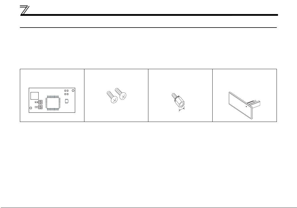
1.2.1 Product confirmation
Check the enclosed items.
Plug-in option
.........................................1
Mounting screw (M3 × 6mm)
............ 2 (Refer to page 14.)
Hex-head screw for option
mounting (5.5mm)
............. 1 (Refer to page 14.)
5.5mm
Communication option LED
display cover
............ 1 (Refer to page 13.)
2
PRE-OPERATION INSTRUCTIONS
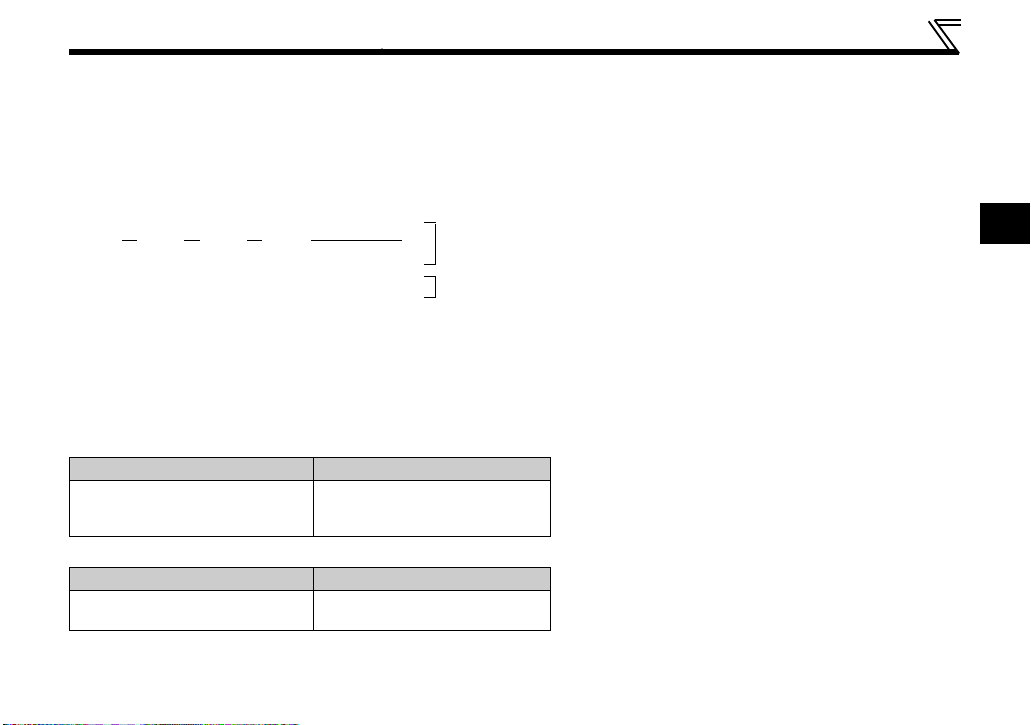
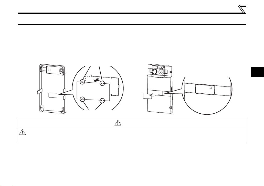
1.2.2 SERIAL number check
The plug-in option is compatible with the inverter having the following SERIAL number or later.
Check the SERIAL number indicated on the inverter rating plate or package.
z SERIAL number check
Refer to the inverter manual for the location of the rating plate.
Rating plate example
Symbol Year Month Control number
The SERIAL consists of one symbol, two characters indicating production year and month, and six characters indicating control number.
The last digit of the production year is indicated as the Year, and the Month is indicated by 1 to 9, X (October), Y (November), or Z (December.)
(1) PU/NET operation switchover (X65 signal) specification
The inverters with the following SERIAL are operated in the PU/NET operation switchover (X65 signal)
specification when connected with FR-A7NF.
z FR-A700 series
FR-A720-(-NA),
FR-A740FR-CA70-EC, FR-CA70-ECT
z FR-F700 series Japanese specification
FR-F720-0.75K to 110K,
FR-F740-0.75K to 560K
Regardless of their SERIAL numbers, all FR-F700P series inverters are operated with the PU operation interlock
(X12 signal) specification.
{ { {{{{{{
TC{{{A{{{G{{ TC number
Model SERIAL number
(-NA)(-EC)(-CHT),
Model SERIAL number
7X{{{{{{ to
03{{{{{{
91{{{{{{ or later
SERIAL
1
3

PRE-OPERATION INSTRUCTIONS
z FR-F700 series NA specification
Model SERIAL number
FR-F720-00046 to 04750-NA,
FR-F740-00023 to 12120-NA
z FR-F700 series EC specification
Model SERIAL number
FR-F740-00023 to 00620-EC,
FR-CF70-EC, FR-CF70-ECT
z FR-F700 series CHT specification
Model SERIAL number
FR-F740-0.75K to 55K-CHT,
FR-F740-S75K to S630K-CHT
91{{{{{{ or later
95{{{{{{ or later
93{{{{{{ or later
4

PRE-OPERATION INSTRUCTIONS
(2) PU operation interlock (X12 signal) specification
The FR-F700P series and the inverters with the following TC and SERIAL numbers are operated in the PU
operation interlock (X12 signal) specification when connected with FR-A7NF.
z FR-A700 series Japanese and NA specification
Model SERIAL number
FR-A720- (-NA)
FR-A740-
(-NA)
04{{{{{{
z FR-A700 series EC specification
Model TC number SERIAL number
FR-A740-00023 to 00052-EC
FR-A740-00083/00126-EC
FR-A740-00170/00250-EC
FR-A740-00310/00380-EC
FR-A740-00470/00620-EC
FR-CA70-EC
(Control unit)
FR-CA70-ECT
(Control unit)
TC{{{A{{{G7{ C0{{{{{{{ or later
TC{{{A{{{G8{ A0{{{{{{{ or later
TC{{{A{{{G7{ C0{{{{{{{ or later
TC{{{A{{{G8{ B0{{{{{{{ or later
TC{{{A{{{G7{ Y0{{{{{{{ or later
TC{{{A{{{G8{ Z0{{{{{{{ or later
TC{{{A{{{G7{ Z0{{{{{{{ or later
TC{{{A{{{G8{ B0{{{{{{{ or later
TC{{{A{{{G7{ Y0{{{{{{{ or later
TC{{{A{{{G8{ Z0{{{{{{{ or later
TC{{{A{{{G7{ V0{{
TC{{{A{{{G8{ E0{{{{{{{ or later
TC{{{A{{{G7{ S0{{{{{{{ or later
TC{{{A{{{G8{ E0{{{{{{{ or later
{{{{{ or later
1
5

PRE-OPERATION INSTRUCTIONS
z FR-A700 series CHT specification
Model TC number SERIAL number
FR-A740-0.4K to 1.5K-CHT
FR-A740-2.2K/3.7K-CHT
FR-A740-5.5K/7.5K-CHT
FR-A740-11K/15K-CHT
FR-A740-18.5/22K-CHT
FR-A740-30K to 45K-CHT
FR-A740-55K-CHT
FR-A740-75K/90K-CHT
FR-A740-110K-CHT
FR-A740-132K-CHT
FR-A740-160K/185K-CHT TC{{{A{{{G7{ W0{{{{{{{ or later
FR-A740-220K to 280K-CHT TC{{{A{{{G7{ V0{{
FR-A740-315K/355K-CHT TC{{{A{{{G7{ U0{{{{{{{ or later
FR-A740-400K to 500K-CHT TC{{{A{{{G7{ R0{{{{{{{ or later
TC{{{A{{{G7{ A0{{{{{{{ or later
TC{{{A{{{G8{ Y0{{{{{{{ or later
TC{{{A{{{G7{ A0{{{{{{{ or later
TC{{{A{{{G8{ Z0{{{{{{{ or later
TC{{{A{{{G7{ W0{{{{{{{ or later
TC{{{A{{{G8{ X0{{{{{{{ or later
TC{{{A{{{G7{ X0{{{{{{{ or later
TC{{{A{{{G8{ Z0{{{{{{{ or later
TC{{{A{{{G7{ W0{{{{{{{ or later
TC{{{A{{{G8{ X0{{{{{{{ or later
TC{{{A{{{G7{ X0{{
TC{{{A{{{G8{ V0{{{{{{{ or later
TC{{{A{{{G7{ W0{{{{{{{ or later
TC{{{A{{{G8{ V0{{{{{{{ or later
TC{{{A{{{G7{ V0{{{{{{{ or later
TC{{{A{{{G8{ F0{{{{{{{ or later
TC{{{A{{{G7{ X0{{{{{{{ or later
TC{{{A{{{G8{ G0{{{{{{{ or later
TC{{{A{{{G7{ W0{{{{{{{ or later
TC{{{A{{{G8{ G0{{{{{{{ or later
{{{{{ or later
{{{{{ or later
6
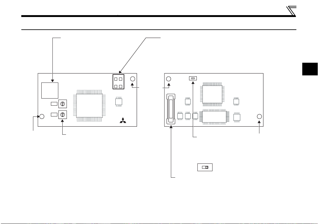
1.3 Parts
PRE-OPERATION INSTRUCTIONS
FR-A7NF
Mounting
hole
Connector for communication
Connect to the network by
connecting a FL-net dedicated
LED (operation status indication)
Lit/flicker/OFF of the LED indicate inverter
operation status.
cable.
Front view Rear view
D1 D2
SW2
0
1
9
2
8
3
X10
7
4
6
5
0
1
9
2
8
3
X1
7
4
6
5
SW1
Node address switch
Set the node address.
(Refer to page 16)
D3 D4
Mounting
hole
Connector
Connect to the inverter option connector.
(Refer to page 8)
SW3
Switch for manufacturer
setting
Do not change from
initially-set status (OFF).
SW3
N
2
L
O
1
Mounting
hole
7
PRE-OPERATION INSTRUCTIONS
D1 D2
S
D3 D4
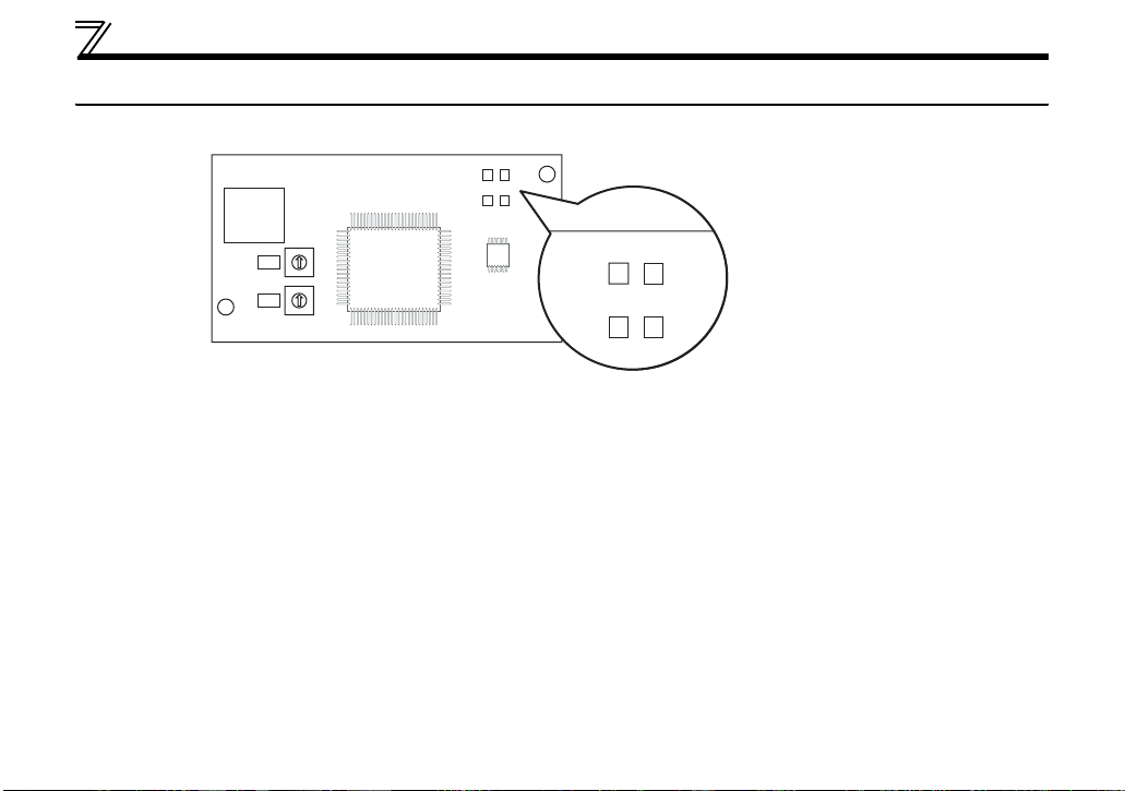
1.4 LED status
Each LED indicates the operating status of the option unit and network according to the indication status.
D1 D2
D3 D4
SW2
0
1
9
2
8
3
X10
7
4
6
5
0
1
9
2
8
3
X1
7
4
6
5
SW1
FR-A7NF
D1: Communication set status LED (CHG)
D2: Device status LED (DEV)
D3: Reception/transmission LED (TX/RX)
D4: Remote status LED (RMT)
8

PRE-OPERATION INSTRUCTIONS
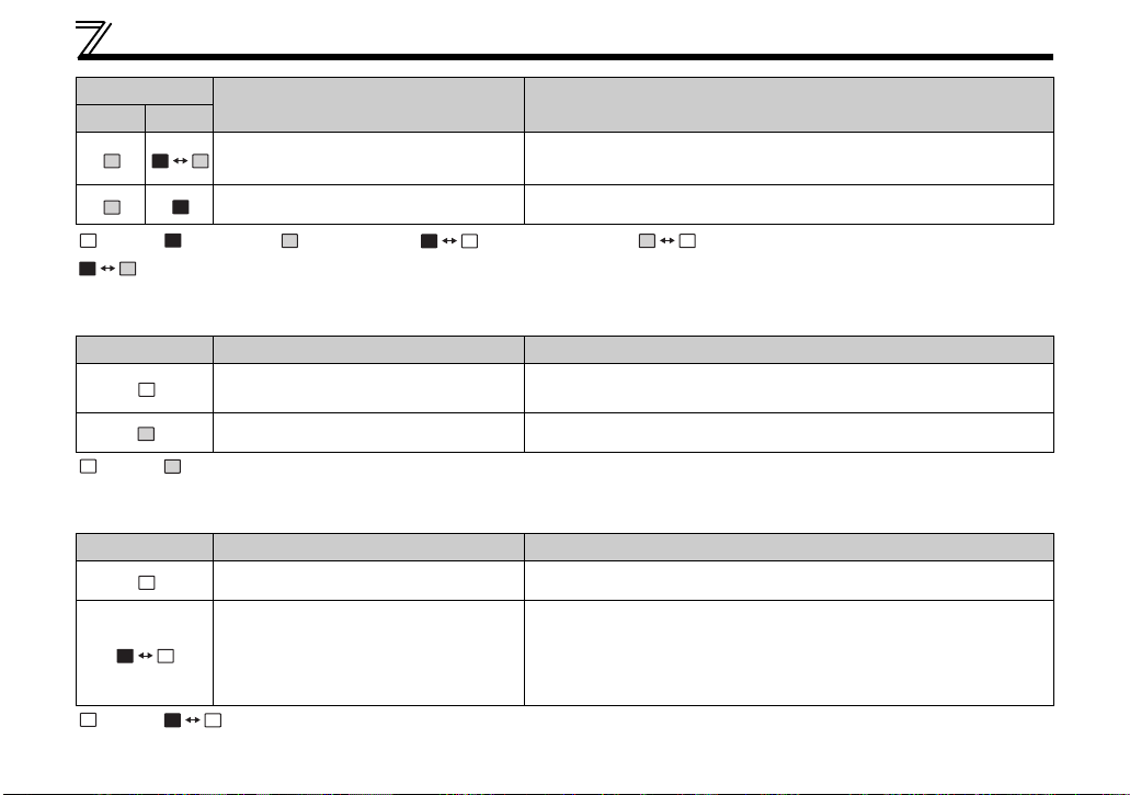
1.4.1 Device status LED (DEV), remote status LED (RMT)
LED Status
DEV RMT
Node Status Description
Power is OFF The inverter power is OFF.
· Node address is out of range (other than 1 to 64).
· Optional board fault
· When mounted to the inverter which is not compatible with
Hardware fault
FL remote network is not connected
FL remote network at a remote stop
FL remote network
during remote connection
processing
Master is not present When the master is disconnected from FL remote network.
FL remote network
during remote operation
Own node is disconnected When the own node is disconnected from FL remote network.
the FR-A7NF (Refer to page 3 for the inverter which is
compatible with the FR-A7NF)
· When a contact fault occurs in an option connector between
the inverter and communication option.
Although hardware is normal, it is not connected to the FL
remote network.
It is correctly set to connect to the FL remote network and
waiting for remote I/O control.
Although remote I/O control started, initial processing is in
progress.
During remote I/O control
1
9
PRE-OPERATION INSTRUCTIONS
LED Status
DEV RMT
Node Status Description
Setting error
Duplicate node When node address is duplicate with other node address
Although it is connected to the FL remote, setting error is found.
(When the slave is not the one the master is expected.)
:OFF, : red is lit, : green is lit, :red is flickering, : green is flickering,
: red and green are alternately flickering
1.4.2 Transmitting (TX)/receiving (RX) LED
LED Status Node Status Description
Not transmitting (TX)/not receiving
(RX)
Transmitting (TX)/receiving (RX) Flickers at high speed during continuous transmitting/receiving
———
:OFF, : green is lit
1.4.3 Communication set status LED (CHG)
LED Status Node Status Description
Communication setting is not changed
Communication setting is changed
:OFF, : red is flickering
The red LED flickers when the applied setting and the node
address switch setting differ. The setting value of the node
address switch is applied by re-powering ON the inverter in this
status, then communication setting status LED turns OFF.
———
10

PRE-OPERATION INSTRUCTIONS
1.5 Specifications
1.5.1 Inverter option specifications
Power supply Supplied from the inverter
Typ e Inverter plug-in option (can be mounted/dismounted to/from the inverter front face)
FL-net dedicated cable Refer to page 18
1.5.2 Communication specifications
Maximum number of
connectable inverters
Communication speed Auto negotiation (auto detection) (10Mbps/100Mbps)
Topology
Communication
distance
Electrical interface Conforms to IEEE802.3u (conforms to CSMA/CD)
Transmission protocol FL remote
Node address setting
I/O points Input 64 points, output 64 points
64 units maximum
· Star (connection with a hub in the center)
· Star bus (connection with multiple hubs)
· Between node ⇔ hub: 100m maximum (Node indicate master and inverters.)
· Between hubs: 100m maximum
· Overall length: 2000m maximum
Can be set with node address switch (Refer to page 16).
The setting is applied to IP address as well.
(192.168.250.node address)
1
11
2 INSTALLATION
2.1 Pre-installation instructions
Make sure that the input power of the inverter is OFF.
CAUTION
With input power ON, do not install or remove the plug-in option. Otherwise, the inverter and
plug-in option may be damaged.
Static electricity in your body must be discharged before you touch the product. Otherwise the
product may be damaged.
12
INSTALLATION
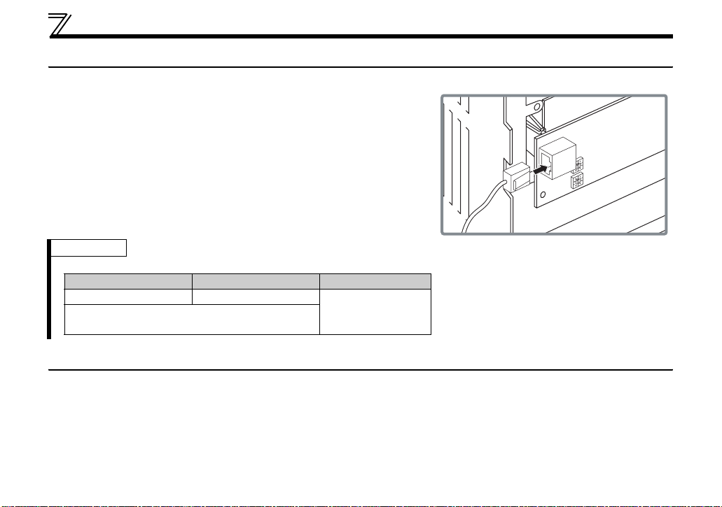
2.2 Installation of the communication option LED display cover
Mount the cover for displaying the operation status indication LED for the communication option on the
inverter front cover.
1)
Cut off hooks on the rear of the inverter front
cover with nipper, etc. and open a window for
fitting the LED display cover.
Cut off with a nipper, etc.
2)
Fit the communication option LED display
cover to the front of the inverter front cover
and push it into until fixed with hooks.
Fit it so that the position of
lenses is in the upper-right
of the LED display cover.
Fitting drawing
Cut off with a nipper, etc.
CAUTION
Take caution not to hurt your hand and such with portions left by cutting hooks of the rear of
the front cover.
2
13
INSTALLATION
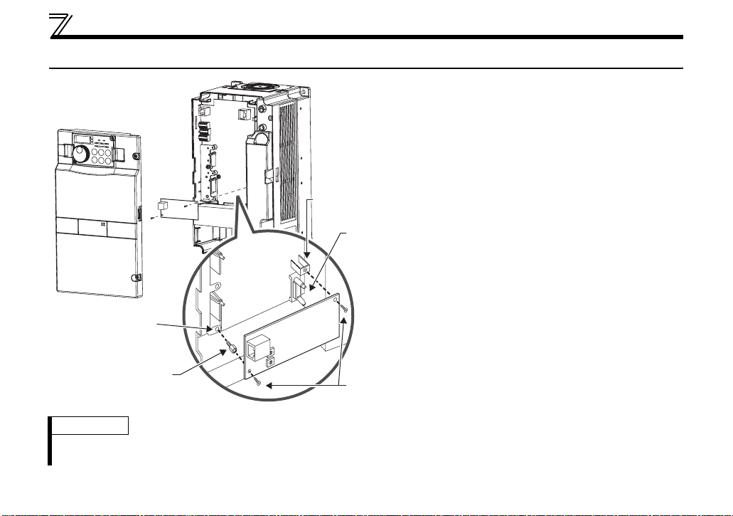
2.3 Installation procedure
1) Remove the inverter front cover.
1)
2) Mount the hex-head screw for option
mounting into the inverter screw hole
(on earth plate) (size 5.5mm, tightening
torque 0.56Nxm to 0.75Nxm).
Screw hole for
option mounting
Inverter side
option
connector
3) Securely fit the connector of the plug-in
option to the inverter connector along
the guides.
4) Securely fix the both right and left sides
of the plug-in option to the inverter with
the accessory mounting screws.
(Tightening torque 0.33Nxm to
0.40Nxm)
If the screw holes do not line up, the
connector may not have been plugged
securely. Check for loose plugging.
Screw hole for
option mounting
(on earth plate)
Hex-head screw
for option mounting
2)
3)
1
2
0
3
9
4
8
5
7
6
1
2
0
3
9
4
8
5
7
6
4)
Mounting
screws
REMARKS
• Remove a plug-in option after removing two screws on both left and right sides.
(The plug-in option is easily removed if the control circuit terminal block is removed before.)
14
INSTALLATION
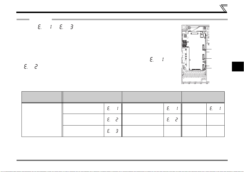
CAUTION
• One of " to " (option fault) appears when the inverter cannot rec-
ognize the option because it is improperly mounted, etc. One of the faults also
appears when an incompatible option is mounted to the inverter. Different indication will appear according to the mounted position (connector 1, 2, or 3).
• For an inverter having several option connectors, use the bottom connector to
mount the option.
If it is connected to a connector other than the bottom connector, " " or
" " (option fault) will appear and its operation will be disabled. Different
indication will appear according to the mounted position (connector 1 or 2).
• The number of option connectors differs by the model. The table below shows
how the fault indication differs according to the number of connectors and their
positions.
Number of option
connectors
Mounting position
and fault indication
3 2 1
Connector 1
(top connector)
Connector 2
(middle connector)
Connector 3
(bottom connector)
Connector 1
(top connector)
Connector 2
(bottom connector)
⎯⎯⎯⎯
Example of FR-A700
Connector 1
⎯⎯
(Refer to Chapter 1 of the inverter's Instruction Manual for the number of option connectors.
• Take caution not to drop a hex-head screw for option mounting or mounting screw during mounting and
removal.
• Pull out the option straight to remove. Otherwise, the connector may be damaged.
Connector 1
Connector 2
Connector 3
2
15
INSTALLATION
2.4 Node address setting
Set the node address between "1 to 64" using node address switches on the FR-A7NF (Refer to page 7).
The setting is applied when the power turns OFF once, then ON again.
Set the arrow (×) of the corresponding switches to the number to set a desired address.
z Setting example
Node address 1:
Set the "×" of X10(SW1) to "0" and the
X10
"×" of X1(SW2) to "1".
X1
CAUTION
• Set the node address switch to the switch number position correctly. If the switch
is set between numbers, normal data communication can not be established.
• If the node address switch is set to a value other than "1 to 64", it is invalid due to outside of setting
range. In this case, DEV LED of the option is lit red and E.OPT appears on the operation panel of the
inverter.
• You cannot set the same node address to other devices on the network. (Doing so disables proper
communication.)
• Set the inverter node address before switching ON the inverter and do not change the setting while
power is ON. Otherwise you may get an electric shock.
• Changes in the node address setting are applied only at the next power-ON. Therefore, if the node
address setting is changed, make sure to power OFF and ON the inverter power.
Node address 26:
0
1
9
2
8
3
7
4
Set the "×" of X10(SW1) to "2" and the
6
5
"×" of X1(SW2) to "6".
0
1
9
2
8
3
7
4
6
5
Good
example
0
1
9
2
8
3
7
4
6
5
X10
X1
Bad
example
9
8
7
6
0
1
9
2
8
3
7
4
6
5
0
1
9
2
8
3
7
4
6
5
0
1
2
3
4
5
16
3 WIRING
3.1 Connection to network
(1) Be sure to check the following before connecting the inverter to the network.
· Check that the FR-A7NF is correctly mounted to the inverter. (Refer to page 14)
· Check that the correct node address is set. (Refer to page 16)
· Check that the FL-net dedicated cable is correctly connected to the FR-A7NF. (Refer to page 18)
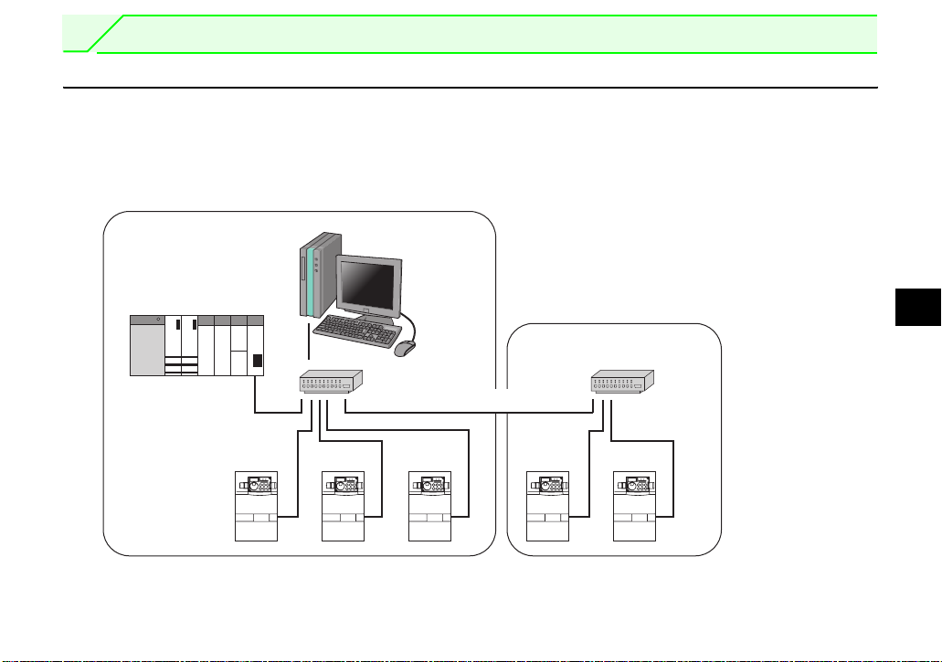
(2) System configuration
Segment 1
Master
100m maximum)
(
Personal computer
Segment 2
Hub
Cascade connection (100m maximum)
Inverter Inverter Inverter Inverter Inverter
Overall length: 2000m maximum
3
Hub
17
WIRING
3.2 Cable specifications
Connect the FR-A7NF option unit to the FL remote network using the FL-net dedicated cable below.
Cables : TPCC5 or more (Twisted Pair Communication Cable
for LAN Category 5)
For the shape, use STP (Shielded Twisted Pair)
(according to the 100BASE-TX(IEEE802.3u)
standard)
Maximum wiring length:100m maximum between hub and inverter.
(according to the 100BASE-TX
(IEEE802.3u) standard)
REMARKS
y FL-net dedicated cable...recommended product (as of July 2011)
Typ e Cable Length (m) Maker
FLG-S-{{{ 1m to 100m
(Example: when the cable length is 1m)
FLG-S-010
Shinwa Co., Ltd.
3.3 Precautions for system configuration
Enough safety measures are necessary when installing the FL-net dedicated cable and connecting to the
FL remote network.
Consult the network provider and network administrator (person in charge of network planning and IP
address management) including terminal treatment of connection cable, construction of trunk cable, etc.
We are not responsible for system troubles from connecting to the FL remote network.
18
WIRING
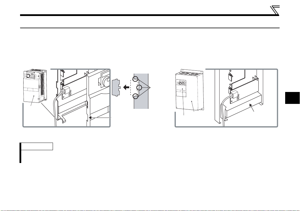
3.4 Wiring
For wiring of the inverter which has one front cover, route wires between the control circuit terminal block
and front cover. If cables can not be routed between the control circuit terminal block and front cover (about
7mm), remove a hook of the front cover and use a space become available.
For wiring of the inverter which has front cover 1 and 2, use the space on the left side of the control circuit
terminal block.
Cut off
1
2
0
3
9
4
8
5
7
6
1
2
0
3
9
4
8
5
7
6
Front cover
Cut off a hook on the inverter
front cover side surface.
(Cut off so that no portion is left.)
Inverter which has one front cover Inverter which has front cover 1 and 2
REMARKS
⋅ When the hook of the inverter front cover is cut off for wiring, the protective structure (JEM1030) changes to open
type (IP00).
with a
nipper,
etc.
Front cover 1
Front cover 2
1
2
0
3
9
4
8
5
7
6
1
2
0
3
9
4
8
5
7
6
Control circuit
terminal block
3
19

WIRING
C
AUTION
Do not connect the parameter unit (FR-PU07, etc.) to the FR-A7NF communication connector.
Doing so will damage the option.
When performing wiring using the space between the inverter front cover and control circuit
terminal block, take care not to subject the cable to stress.
After wiring, wire offcuts must not be left in the inverter. They may cause an error, failure or
malfunction.
20

4 INVERTER SETTING
4.1 Parameter list
zThe following parameters are used for the communication option (FR-A7NF)
Parameter
Number
37 Speed display 0, 1 to 9998 1 0 37
144 Speed setting switchover
501
*
* Parameters which can be displayed when the plug-in option (FR-A7NF) is mounted.
Communication error occurrence
count display
Name Setting Range
0, 2, 4, 6, 8, 10, 102,
104, 106, 108, 110
01032
Minimum
Setting
Increments
1437
Initial
Value
Refer to
Page
4
21

INVERTER SETTING
zParameters whose functions are always the same
When the FR-A7NF is mounted to the inverter, following parameter functions are always the same.
(Changed setting is invalid even if the setting value is changed.)
Parameter
Number
79 Operation mode selection
180 RL terminal function selection 0 Low-speed operation command
181 RM terminal function selection 1 Middle-speed operation command
182 RH terminal function selection 2 High-speed operation command
183 RT terminal function selection 3 Second function selection
184 AU terminal function selection 9999 — (no function)
185 JOG terminal function selection 9999 — (no function)
186 CS terminal function selection 9999 — (no function)
187 MRS terminal function selection 24 Output stop
188 STOP terminal function selection 9999 — (no function)
189 RES terminal function selection
190 RUN terminal function selection 0 Inverter running
191 SU terminal function selection 1 Up to frequency
192 IPF terminal function selection 2 Instantaneous power failure/undervoltage
193 OL terminal function selection 3 Overload alarm
194 FU terminal function selection 4 Output frequency detection
195 ABC1 terminal function selection 99 Fault output
196 ABC2 terminal function selection 9999 — (no function)
338
339
Communication operation
command source
Communication speed command
source
Name Setting
*3 Network operation mode 25
0
7
*4 PU operation interlock 25
*3 PU/NET operation switchover
65
12 *4 PU operation interlock
0 Operation command source communication 30
0 Speed command source communication 30
Function
Refer
to Page
— *2
— *2
— *2
— *2
— *2
— *2
— *2
— *2
— *2
— *2
— *2
— *2
— *2
— *2
— *2
— *2
— *2
— *2
22

INVERTER SETTING
Parameter
Number
340
342
500 *1
502 *1
550
551
*1 Parameters which can be displayed when the plug-in option (FR-A7NF) is mounted.
*2 Refer to the inverter manual for details.
*3 This setting is for the inverters with the PU/NET operation switchover (X65 signal) specification.
*4 This setting is for the inverters with the PU operation interlock (X12 signal) specification. (Refer to page 5)
The X12 signal is valid only when it is input via FL remote communication. (Refer to page 50) (It is invalid when input
from a control circuit terminal of the inverter.)
Communication startup mode
selection
Communication EEPROM write
selection
Communication error execution
waiting time
Stop mode selection at
communication error
NET mode operation command
source selection
PU mode operation command
source selection
Name Setting
10
0
0
1
9999
2
Function
Started in Network operation mode. Operation
mode can be changed between the PU
operation mode and Network operation mode
from the operation panel.
Parameter values written by communication are
written to the EEPROM and RAM.
There is no waiting time since the communication
line fault occurrence until communication error
(0s). Note that actual time depends on the
detection time on FL remote network.
The inverter decelerates to stop at
communication fault occurrence, when provide
a fault output.
Automatic communication option recognition
Normally, control source of the RS-485 terminal
is valid. When a communication option is
mounted, the control source of the
communication option is valid.
Selects the PU connector as the PU operation
mode operation source.
(Refer to page 3)
Refer
to Page
25
— *2
— *2
33
4
— *2
— *2
23

INVERTER SETTING
4.2 Operation mode setting
Powering ON the inverter with the communication option (FR-A7NF) mounted starts the inverter in Network
operation mode.
(1) Network operation [NET] ... Controls the inverter with instructions from the network via the
communication option.
Functions of Pr.79 and Pr.340 are always the same when the FR-A7NF is
mounted.
(2) PU operation [PU].............. Controls the inverter from the key of the operation panel (FR-DU07)
mounted on the inverter or parameter unit (FR-PU07/FR-PU04).
(3) External operation [EXT] ...Controls the inverter by switching ON/OFF external signals connected to
the control circuit terminals of the inverter.
(The operation mode can not be changed to External operation mode when
the FR-A7NF is mounted.)
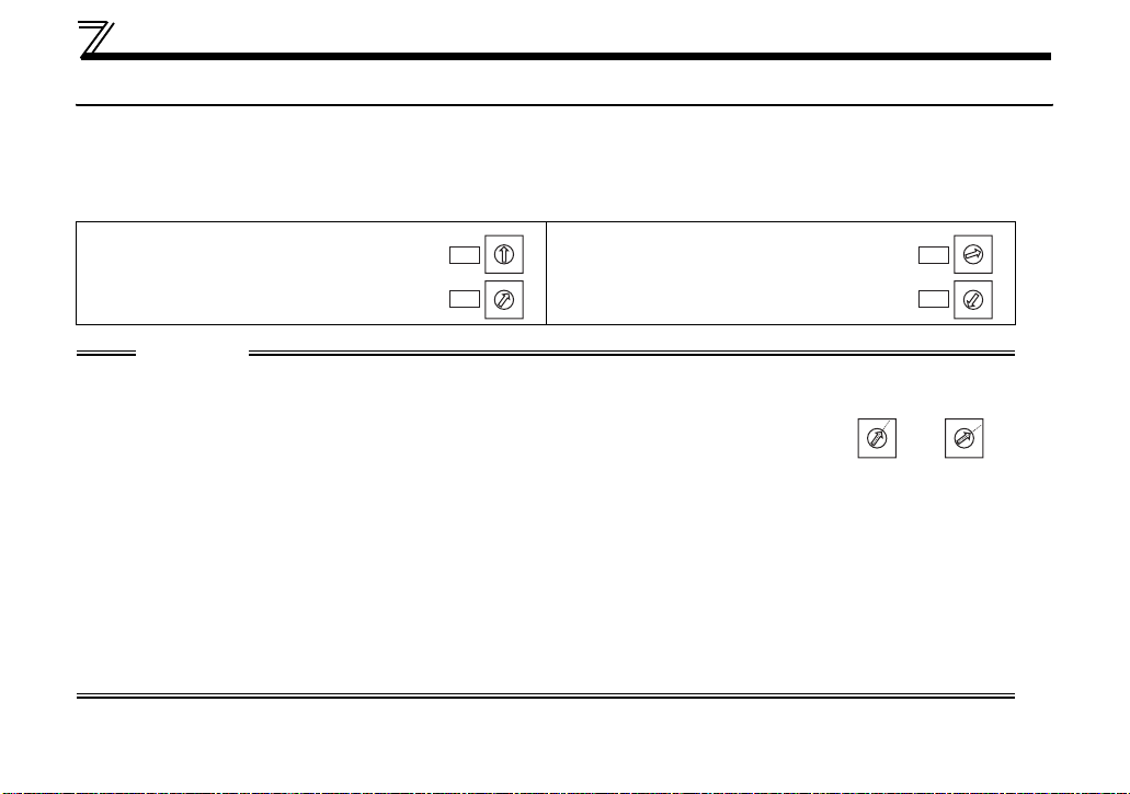
4.2.1 Operation mode indication
FR-DU07
Operation mode indication
(The inverter operates according to the LED lit mode.)
PU: PU operation mode
EXT: External operation mode
NET: Network operation mode *2
*1 The operation mode can not be changed to External operation mode when the FR-A7NF is mounted.
*2 "NET" is displayed when the FR-A7NF is mounted.
*1
24

4.2.2 Operation mode switchover method
Power-on
*
Network operation
C
External operation
INVERTER SETTING
A
PU operation
D
E
F
* When powering ON the inverter with the FR-A7NF mounted, the inverter starts in Network operation mode.
B
4
25

INVERTER SETTING
zOperation mode switchover
Symbol Switchover Type Switchover Method
The operation mode can not be switched in power-ON status. After powering OFF
External operation →
A
PU operation
the inverter, remove the FR-A7NF, then power ON the inverter again. Then, press
the of the PU (FR-DU07/FR-PU07/FR-PU04).
B
C
D
E
F
PU operation →
External operation
Network operation →
External operation
External operation →
Network operation
Network operation →
PU operation
PU operation →
Network operation
The operation mode can not be switched in power-ON status. After powering OFF
the inverter, remove the FR-A7NF, then power ON the inverter again.
The operation mode can not be switched in power-ON status. After powering OFF
the inverter, mount the FR-A7NF to the option connector (option connector 3 for
FR-A700 series), then power ON the inverter again.
Turn ON the PU/NET operation switchover signal. (Refer to page 27)
*1
Turn ON the X12 signal (Bit11), which gives operation commands through FL
remote communication, and press on the PU (FR-DU07/FR-PU07/FR-
PU04). (Refer to page 28)
Turn OFF the PU/NET operation switchover signal. (Refer to page 27)
*2
*1
Turn OFF the X12 signal (Bit11), which gives operation commands through FL
remote communication. (Refer to page 28)
*2
*1 This setting is for the inverters with the PU/NET operation switchover (X65 signal) specification. (Refer to page 3)
*2 This setting is for the inverters with the PU operation interlock (X12 signal) specification. (Refer to page 5)
26

INVERTER SETTING
(1) Operation mode switching by the PU/NET operation switchover signal (X65)
Combination of the FL remote communication control input command (PU/NET signal) (refer to page 49)
and the external terminal RES (X65 signal) determines ON/OFF of the PU/NET operation switchover
signal and the operation mode as shown in the below table.
Note that operation mode can be changed only during a stop (during a motor stop, start command (STF,
STR) is OFF).
FL remote communication control input command
(PU/NET signal)
RES terminal of external terminal (X65 signal) OFF OFF ON ON
PU/NET operation switchover signal (Operation mode) OFF (NET) ON (PU) ON (PU) ON (PU)
OFF ON OFF ON
PU: PU operation mode
NET: Net work operation mode
REMARKS
• This function is available for the inverters with the SERIAL numbers on page 3.
4
27

INVERTER SETTING
(2) Operation mode switching by the PU operation interlock signal (X12)
PU operation interlock is a function that forcefully changes the operation mode to the Network operation
mode at turn-OFF of the X12 signal (Bit 11), which gives operation commands through FL remote
communication.
This function prevents the operation mode from being accidentally unswitched from the PU operation
mode. If the operation mode left unswithced from the PU operation mode, the inverter does not reply to the
commands sent through FL remote communication.
X12
signal
ON
OFF
Operation mode Parameter write
Operation mode (PU, NET) switching is enabled
Output stop during Network operation
Forcibly switched to Network operation mode
Network operation is enabled
Switching to the PU operation mode is disabled
Function/Operation
Parameter write is enabled (depending on Pr. 77
Parameter write selection and each parameter write
conditions. Refer to the Inverter Manual for details.)
Parameter write is disabled
(Note that the Pr.297 setting is available
when Pr.296 ≠ "9999.")
REMARKS
• This function is available for the inverters with the SERIAL numbers on page 5.
28

INVERTER SETTING
<Function/operation changed by switching ON-OFF the X12 signal>
Operating Condition
Operation
mode
PU
Network
*1 The operation mode switches to the Network operation mode independently of whether the start signal (STF,
STR) is ON or OFF. Therefore, the motor is run in the Network operation mode when the X12 signal is turned OFF
with either of STF and STR ON.
*2 At fault occurrence, pressing of the operation panel resets the inverter.
Status
During stop ON → OFF
Running ON → OFF
During stop
Running
X12 Signal
OFF → ON
ON → OFF Disallowed
OFF → ON During operation → output stop Disallowed
ON → OFF Output stop
Operation
Mode
*1
*1 Disallowed
Network *2
Operating Status
If Network operation frequency
setting and start signal are
entered, operation is performed
in that status.
During stop
→ operation Disallowed
Switching to PU
Operation Mode
Disallowed
Allowed
CAUTION
⋅ If the X12 signal is ON, the operation mode cannot be switched to the PU operation mode when the start
signal (STF, STR) is ON.
⋅ The X12 signal is valid only when it is input via FL remote communication. (The X12 signal is invalid when it
is input from a control circuit terminal of the inverter.)
⋅ When the FR-A7NF is mounted, Pr.79 Operation mode selection and Pr.340 Communication startup mode selection
settings are invalid.
4
29

INVERTER SETTING
4.3 Selection of control source for the Network operation mode
⋅ As control sources, there are operation command source that controls signals related to the start
command and function selection of the inverter and speed command source that controls signals related
to frequency setting.
⋅ Commands from external terminal and communication are as listed below when the FR-A7NF is mounted.
Operation command
Running frequency from communication NET —
Terminal 2 — —
Terminal 4 — —
Terminal 1 Compensation —
Low-speed operation command/ remote setting
clear
Middle-speed operation command/ remote
setting deceleration
High-speed operation command/ remote setting
acceleration
PU operation interlock NET —
*2
PU/NET operation switchover *3 Combined —
*1
Fixed functions
(Functions
equivalent to
terminals)
Terminal RL
Terminal RM
Terminal RH
Terminal RT Second function selection NET —
Terminal RES
(X12)
Terminal RES
(X65)
Terminal MRS Output stop Combined —
Operation valid
location
NET
NET
NET
Remarks
Pr. 59 = "0"
(multi-speed)
Pr. 59 = "1, 2" (remote)
30

INVERTER SETTING
Operation valid
location
Remarks
Pr. 59 = "0"
(multi-speed)
Pr. 59 = "1, 2" (remote)
Operation
command
through FL
remote
communication
Operation command
STF signal Forward rotation command NET —
STR signal Reverse rotation command NET —
RL signal Low-speed operation command NET
RM signal Middle-speed operation command NET
RH signal High-speed operation command NET
RT signal Second function selection NET —
X12 signal
MRS signal Output stop NET —
PU/NET signal
Error reset Error reset NET —
*2 PU operation interlock NET —
*1
PU/NET operation switchover *3 NET —
*1 This setting and signal are for the inverters with the PU/NET operation switchover (X65 signal) specification.
(Refer to page 3)
*2 This setting and signal are for the inverters with the PU operation interlock (X12 signal) specification.
(Refer to page 5)
*3 Functions of "RES terminal (X65 signal) of external terminal" and "FL remote communication control input
command (PU/NET signal)" are the same.
[Explanation of table]
NET :Control from network is only valid
Combined :Operation from either external terminal or communication is valid.
⎯ :Operation from either external terminal or computer is invalid.
Compensation :Control by signal from external terminal is only valid if Pr. 28 Multi-speed input compensation setting is "1".
CAUTION
• The settings of Pr. 338 Communication operation command source and Pr. 339 Communication speed command source
are invalid when used with the FR-A7NF.
4
31

INVERTER SETTING
4.4 Operation at communication error occurrence
4.4.1 Operation selection at communication error occurrence (Pr. 501, Pr. 502)
You can select operations at communication error occurrences by setting Pr. 501 and Pr. 502 under network
operation.
(1) Display and erasure of communication error occurrence count
The cumulative number of communication error occurrences can be indicated.
Writing "0" to Pr.501 Communication error occurrence count display erases this cumulative count.
Parameter
Number
501
Name Setting Range
Communication error
occurrence count display
010
Minimum Setting
Increments
Initial Value
Count timing depending on
communication line status
Normal Error
Incremented by 1
Normal Error
Incremented by 1
At the point of communication line error occurrence, Pr. 501 Communication error occurrence count
display is incremented by 1.
CAUTION
• The communication error count occurrence is stored into RAM temporarily. Since this data is stored in
EEPROM at one-hour intervals, performing power-ON reset or inverter may cause the Pr. 501 data to be the
value stored in EEPROM the last time depending on the reset timing.
32

INVERTER SETTING
(2) Inverter operation at communication error occurrence
If a communication line error or an error of the option unit itself occurs when the FR-A7NF is mounted,
the inverter operates in the same manner as when Pr. 502 Stop mode selection at communication error =
"1" regardless of setting value of Pr. 502.
zOperation at error occurrence
Error Definition Operation Indication Fault Output
Communication line Decelerated to stop
Communication option itself Decelerated to stop E.1, E.2 or E.3 lit after stop Provided after stop
E.OP1, E.OP2 or E.OP3 lit after
stop
Provided after stop
zOperation at error removal
Error Definition Operation Indication Fault Output
Communication line Kept stopped E.OP1, E.OP2 or E.OP3 kept lit Kept provided
Communication option itself Kept stopped E.1, E.2 or E.3 kept lit Kept provided
CAUTION
• A communication line error [E.OP1 (fault data: HA1), E.OP2 (fault data:HA2), E.OP3 (fault data: HA3)] is an
error that occurs on the communication line, and an error of the communication option unit itself [E. 1 (fault
data: HF1), E. 2 (fault data:HF2), E. 3 (fault data: HF3)] is a communication circuit error in the option.
• The fault output indicates fault output signal (terminal ABC1) or fault bit output.
• When the setting was made to provide a fault output, the fault record is stored into the faults history. (The
fault record is written to the faults history when a fault output is provided.)
When no fault output is provided, the error record overwrites the fault indication of the faults history
temporarily, but is not stored.
After the error is removed, the fault record is reset and returns to the ordinary monitor, and the faults
history returns to the preceding fault indication.
• The deceleration time is the ordinary deceleration time setting (e.g. Pr. 8, Pr. 44, Pr. 45).
4
33

INVERTER SETTING
4.4.2 Fault and measures
(1) The inverter operates as follows at fault occurrences.
Fault
Location
Inverter
Communication
line
Communication
option
* Depends on the Pr. 502 setting
Inverter operation Inverter trip Inverter trip Inverter trip
Data communication Continued Continued Continued
Inverter operation
Data communication Stop Stop Stop
Communication
option
connection
error
Error of
communication
option itself
Status
Inverter
operation
Data
communication
Inverter
operation
Data
communication
Network
Operation
Decelerated to
stop
Decelerated to
stop
Continued Continued Continued
Decelerated to
stop
Stop Stop Stop
Operation Mode
External
Operation
Continued Continued
Inverter trip * Inverter trip *
Continued Continued
PU Operation
34

INVERTER SETTING
(2) Measures at fault occurrences
Fault Indication Fault Definition Measures
· Check that a cable is not disconnected from the communication
E.OP1, E.OP2, E.OP3
E.OPT
E.1, E.2, E.3
* When faults other than the above are displayed, refer to the inverter manual and remove the cause of the fault.
Communication
option fault
Option fault
connector.
· Check that a cable between own node and other nodes (including
switching hub) is not disconnected.
Check the node address setting. (Refer to page 16)
If an option board becomes faulty, contact your sales representative.
· Mount the communication option to the lowest option connector.
(Refer to page 14)
· Mount a communication option to the inverter compatible with the
FR-A7NF. (Refer to page 3)
· Check the connection between the inverter and option unit for poor
contact, etc. and remove the cause of the error. (Refer to page 14)
4
35

INVERTER SETTING
4.5 Inverter reset
zOperation conditions of inverter reset
Which resetting method is allowed or not in each operation mode is described below.
Operation Mode
Resetting Method
Inverter reset Not allowed
Reset from the network
Input the RES signal via a control circuit terminal of the inverter.
Switch OFF inverter power Enabled Enabled Enabled
Reset from the PU/DU
*1 Inverter reset via Network is invalid.
*2 Reset can be made only when the protective function of the inverter is activated.
*3 As the FR-A7NF is not mounted, reset from network can not be performed.
*4 Set "62 (RES signal)" in Pr. 178 STF terminal function selection or Pr. 179 STR terminal function selection to assign the
function to a terminal.
Error reset at inverter fault
(Refer to page 49)
Inverter reset Enabled Enabled Enabled
Reset at inverter fault Enabled Enabled Enabled
*2
CAUTION
• When E.OP1, E.OP2 or E.OP3 (communication line error) has occurred, reset cannot be made from the
network. Reset the inverter by making a power-ON reset, resetting with RES signal, etc.
• The inverter can not be controlled for about 1s after release of a reset command .
• At reset execution, the inverter resets, but the FR-A7NF continues communication.
• At occurrence of E.1, E.2 or E.3 (Option fault), reset can not be performed from the network. Reset the
inverter by making a power-ON reset, resetting with RES signal, etc.
Network
Operation
Allowed Not allowed *3 Not allowed
*4 Enabled Enabled Enabled
External
Operation
*1 Not allowed *3 Not allowed
PU
Operation
36

INVERTER SETTING
4.6 Frequency and speed conversion specifications
When setting or monitoring a frequency through the FR-A7NF, the frequency is set or monitored in 0.01Hz
increments regardless of the Pr. 37 Speed display setting. When setting or monitoring a speed through the
FR-A7NF, the speed is calculated with Pr.144 Speed setting switchover as shown below.
Speed setting, monitoring (1r/min increments) = frequency × 120 / number of motor poles (Pr. 144*)
* When Pr. 144 = "102 to 110," the formula is calculated with the value of (Pr. 144 - 100). When Pr. 144 ="0," the
formula is calculated with 4 poles.
REMARKS
• Refer to the Instruction Manual of the inverter for details of Pr. 37 and Pr. 144.
4
37

5 FL REMOTE COMMUNICATION FUNCTION
5.1 Functions
5.1.1 Output from the inverter to the network
Main items to be output from the inverter (FR-A7NF) to the network and their descriptions are explained
below. (
{: with function, ×: without function)
Item Description
Inverter monitor
Inverter status Monitors the output signal of the inverter.
Operation mode read Reads the operation mode of the inverter.
Output frequency
read
Parameter read Reads parameter settings of the inverter.
Fault description Monitors the fault history of the inverter.
Monitor various items such as inverter output
current and output voltage.
Monitors the output frequency of the inverter.
Cyclic
Transmission
× {
{{
× {
{{
× {
× {
Message
Transmission
REMARKS
• Refer to the inverter manual for functions controllable from the network in each operation mode.
Refer to
Page
69
53, 67
66
57, 69
72
76
38

FL REMOTE COMMUNICATION FUNCTION
5.1.2 Input to the inverter from the network
Main items which can be commanded from the network to the inverter and their descriptions are explained
below. (
* Parameter writing is available only for the inverters with the SERIAL on page 5. Parameters can be written while
{: with function, ×: without function)
Item Description
Sets the control input command such as
Run command
Frequency setting Sets the running frequency of the inverter.
Parameter write * Sets parameters of the inverter.
Faults history batch
clear
the X12 signal (Bit11), which gives operation commands through FL remote communication, is ON.
forward rotation signal (STF) and reverse
rotation signal (STR).
Clears the fault of the inverter.
Cyclic
Transmission
{ × 49
{ ×
× {
× {
Message
Transmission
REMARKS
• Refer to the inverter manual for functions controllable from the network in each operation mode.
Refer to
Page
51
72
76
5
39

FL REMOTE COMMUNICATION FUNCTION
5.2 Types of data communication
FL remote data communication supports "cyclic transmission" which transmits data periodically (refer to
page 41) and "message transmission" which transmits data non-periodically (refer to page 58).
40
Cyclic transmission
Cyclic data
with token
Message data
Cyclic transmission + message transmission

6 CYCLIC TRANSMISSION
Cyclic transmission transmits data periodically. Each node shares data through common memory. (Refer to
page 42 for common memory. )
Data of I/O area is updated periodically by cyclic transmission.
The master controls the inverter by setting run command (control input command, set frequency, etc.) in
the output data area.
The inverter sets the inverter status (output frequency, output current, various signals, etc.) in the input
data area and sends it to the master.
Data
Node 1 Node 2
Node 1
Node 2
Node 3
Node 4
Node n
Node 1
Node 2
Node 3
Node 4
Node n
Token
FL remote
Node 3
Node 1
Node 2
Node 3
Node 4
Node n
Node
Node 1
Node 2
Node 3
Node 4
Node n
Node n
Node 1
Node 2
Node 3
Node 4
Node n
6
Common
memory
41

CYCLIC TRANSMISSION
6.1 Common memory
Concept of common memory is stated below.
(1) The common memory is used as a shared memory between nodes which perform cyclic transmission.
(2) The common memory has two areas which are "common memory area 1" and "common memory area
2".
Common memory area 1 is I/O data area. Common memory area 2 is the control information area.
Two different areas can be assigned to each node.
(3) When the area each node sends exceed the transmission size (1024 byte) by one frame, data is
transmitted by multiple frames.
(4) When receiving data which are divided into multiple frames as (3), common memory is not updated until
all frames sent from one node are received. Synchronism per node unit is guaranteed.
(5) Entire network has an area of 8k bit (0.5k word) + 8k word = 8.5k word.
The maximum send data capacity per one node is 8.5k word. (Note that one word is 2 byte.)
15
2
0
2
42
Common memory area 1
=Input/output data area
Common memory area 2
=Control information area
0.5k Word
8k Word
Common memory
8.5k Word
area

CYCLIC TRANSMISSION
(6) Among common memory, both common memory area 1 and common memory 2 can be set as a
transmission area of one node as desired within the maximum area.
(7) Each node on FL remote network can share the same data in the whole system by broadcasting data
at a constant period. In addition, each node has own transmission area which does not overlap each
other to exchange data. (For common memory function, the transmission area assigned to one node
is a receive area for other nodes.)
Common memory
of node = 01
(Send)
(Receive)
(Receive)
(Receive)
Common memory
of node = 02
(Receive)
(Send)
(Receive)
(Receive)
Common memory
of node = 03
(Receive)
(Receive)
(Receive)
(Send)
Common memory
of node = 04
(Receive)
(Receive)
(Send)
6
(Receive)
43

CYCLIC TRANSMISSION
6.1.1 Common memory area 1
Size Description Refer to Page
Input data
(Inverter→master)
Output data
→inverter)
(Master
Input data
(Inverter
(Master
* When accessing a message, the access size should be the size stated in the table above.
→master)
Output data
→inverter)
REMARKS
x
When node status is other than "during FL remote network remote operation", all output data is changed to "0".
(Refer to
x When transmitting a message, common memory area 1 and 2 are read only. (Refer to page 63)
page 9
256 words
(512 byte)
256 words
(512 byte)
Virtual address
(byte
boundary)
H00000000 0 4 Input data (#1)
H00000008 4 4 Input data (#2)
H00000010 8 4 Input data (#3)
H000001F0 248 4 Input data (#63)
H000001F8 252 4 Input data (#64)
H00000200 256 4 Output data (#1)
H00000208 260 4 Output data (#2)
H00000210 264 4 Output data (#3)
H000003F0 504 4 Output data (#63)
H000003F8 508 4 Output data (#64)
for change of the setting.)
Data to be sent from inverter to master (4 words).
The data includes inverter status, output frequency, etc.
Data to be sent from master to inverter (4 words).
The data includes start command, frequency command, etc.
Applications
Address
(word boundary)
Size
(word boundary)
:
:
(Number in parentheses indicates
Description
node address)
52
48
44

6.1.2 Common memory area 2
Size
Control information (inverter→master) 1024 word (2048 byte)
Control information (master→inverter) 1024 word (2048 byte)
CYCLIC TRANSMISSION
Virtual address
(byte
boundary)
H00000400 0 1 Slave status (#)
H00000402 1 1 Actual status slave type (#1)
(1) Control information
(inverter
(2) Control information
(master
* When accessing a message, the access size should be the size stated in the table above.
→master)
→inverter)
H00000404 2 14 Simple setting check area (#1)
H00000BE0 1008 1 Slave status (#64)
H00000BE2 1009 1 Actual status slave type (#64)
H00000BE4 1010 14 Simple setting check area (#64)
H00000C00 1024 1 Remote control area (#1)
H00000C02 1025 1 Expected slave type (#1)
H00000C04 1026 14 Simple setting area (#1)
H000013E0 2032 1 Remote control area (#64)
H000013E2 2033 1 Expected slave type (#64)
H000013E4 2034 14 Simple setting area (#64)
Address
(word
boundary)
(word
boundary)
Size
Applications
Description
(Number in parentheses indicates node
:
:
REMARKS
x When sending a message, common memory area 1 and 2 are read only. (Refer to page 63)
address.)
6
45

CYCLIC TRANSMISSION
(1) Control information (inverter→master)
<Slave status>
Value Slave status
0 FL remote network is not connected
1 FL remote network remote at a stop
FL remote network remote connection
2
processing
3 FL remote network remote operating
4 Master is not present
5 Own node is disconnected
6 Setting error
<Actual slave type>
b15 b14 b13 b12 b11 b10 b9 b8 b7 b6 b5 b4 b3 b2 b1 b0
H00 to H3F (One point to 64 point)
Output points
H00 to H3F (One point to 64 point)
Input points
Subsequent area
0: Not used, 1:Used
0: Output not used (0 point)
1: Output used
Subsequent area
0: Not used, 1: Used
0: Input not used (0 point)
1: Input used
<Simple setting check area>
Not used. (Displays data imported in the simple setting area set from the master.)
46

(2) Control information (master→inverter)
<Remote control area>
b15 b14 b13 b12 b11 b10 b9 b8 b7 b6 b5 b4 b3 b2 b1 b0
Not used
<Expected slave type>
Refer to page 46 for <Actual slave type>
<Simple setting check area>
Not used
CYCLIC TRANSMISSION
Remote control flag
0: Remote control stop
1: Remote control start
6
47

CYCLIC TRANSMISSION
6.2 Output data (master to inverter)
[Master output area (from master → inverter)]
Address
Word
0 4(n-1)+256 Control input command (Refer to page 49)
1 4(n-1)+257 — (not used)
2 4(n-1)+258 Set frequency (0.01 Hz increments) (Refer to page51)
3 4(n-1)+259 — (not used)
(word boundary)
(n: node address)
Bit 15 14 13 12 11 10 9 8 7 6 5 4 3 2 1 0
Applications
48

CYCLIC TRANSMISSION
6.2.1 Control input command
Set control input command such as forward and reverse rotation commands.
Bit Signal Description
0 STF signal
1 STR signal
2 RL signal
3 RM signal
4 RH signal
5 RT signal*1
6 to 8
— (not used)
Forward
rotation
command
Reverse
rotation
command
Pr. 59 = 0 (initial value) Low-speed operation command
*1
Pr. 59 = 1, 2
Pr. 270 = 1
Pr. 59 = 0 (initial value) Middle-speed operation command
*1
Pr. 59 = 1, 2
Pr. 59 = 0 (initial value) High-speed operation command
*1
Pr. 59 = 1, 2
*4 Remote setting (setting clear) Pr. 59
*5 Stop-on contact selection 0
*4 Remote setting (deceleration) Pr. 59
*4 Remote setting (acceleration) Pr. 59
0: second function selection invalid,
1: second function selection valid
Pr. 270 = 1
*5 Stop-on contact selection 1
(Always 0) —
Bit0 Bit1 Command
Forward rotation: 0 Reverse rotation: 0 Stop command
Forward rotation: 1 Reverse rotation: 0
Forward rotation: 0 Reverse rotation: 1
Forward rotation: 1 Reverse rotation: 1 Stop command
Forward rotation
command
Reverse rotation
command
Related
Parameter
—
Pr. 4 to Pr. 6,
Pr. 24 to Pr. 27
Pr. 270, Pr. 275,
Pr. 276
Pr. 4 to Pr. 6,
Pr. 24 to Pr. 27
Pr. 4 to Pr. 6,
Pr. 24 to Pr. 27
Pr. 44 to Pr. 51
Pr. 270, Pr. 275,
Pr. 276
6
49

CYCLIC TRANSMISSION
Bit Signal Description
9
10
MRS signal
*1
— (not used)
PU/NET
*1, *2
signal
Output stop
(Always 0) —
PU/NET
operation
switchover
0: output shut off cancel,
1: output shut off
0: Network operation mode,
1: PU operation mode
(Refer to page 27 for details)
Related
Parameter
Pr.17
—
PU operation interlock (Refer to page 28)
Function/Operation
Parameter write is disabled
(Note that the Pr.297 setting is available
when Pr.296 ≠ "9999.")
Parameter write is enabled (depending
on Pr. 77 Parameter write selection and
each parameter write conditions. Refer to
the Inverter Manual for details.)
—
11
12 to 14
X12 signal
*1, *3
— (not used)
Bit11
Forcibly switched to Network operation
mode
0
Network operation is enabled
Switching to the PU operation mode is
disabled
Operation mode (PU, NET) switching is
1
enabled
Output stop during Network operation
Operation mode Parameter write
(Always 0) —
Resets the inverter when the setting of Bit15 is changed from 0 to 1 at
15 Error reset
occurrence of inverter error. Resetting the inverter resets the fault and
initializes the inverter status.
—
(FL remote communication continues.)
*1 Signals of the Bit2 to Bit5, Bit9, and Bit11 can not be changed. Even when changed using Pr.178 to Pr.183, Pr.187
and Pr.189, the settings are invalid. Refer to the inverter manual for details of Pr. 178 to Pr.183, Pr.187 and Pr.189.
*2 This setting is for the inverters with the PU/NET operation switchover (X65 signal) specification. (Refer to page 3)
*3 This setting is for the inverters with the PU operation interlock (X12 signal) specification. (Refer to page 5)
50

CYCLIC TRANSMISSION
*4 When Pr. 59 Remote function selection = "1" or "2", the functions of the RL, RM and RH signals are changed as given
in the table.
*5 When Pr. 270 Stop-on contact/load torque high-speed frequency control selection = "1", functions of RL and RT signals
are changed as in the table. (The setting is available for the FR-A700 series.)
REMARKS
x The values of each bit, "0" and "1," indicate "OFF" and "ON."
6.2.2 Set frequency
The set frequency can be set in 0.01Hz increments.
Bit Range Unit
0 to 15 0.00Hz to 400.00Hz 0.01Hz
Example:
If you want to set 120.00Hz, set 12000, which is the value multiplied by 100.
REMARKS
x Regardless of the Pr. 37 Speed display setting, the value is always set in frequency (Hz).
6
51

CYCLIC TRANSMISSION
6.3 Input data (inverter to master)
[Master input area (inverter → master)]
Address
Word
0 4(n-1)+0 Inverter status monitor (Refer to page 53)
1 4(n-1)+1 Life/warning (Refer to page55) Fault code (Refer to page 55)
2 4(n-1)+2 Output frequency monitor (Refer to page 57)
3 4(n-1)+3 Output current monitor (Refer to page 57)
(word boundary)
(n: node address)
Bit 15 14 13 12 11 10 9 8 7 6 5 4 3 2 1 0
Applications
52

CYCLIC TRANSMISSION
6.3.1 Inverter status monitor
Monitors the output signal of the inverter from the network.
Bit Signal Description Related parameter
During forward
0
rotation
During reverse
1
running
2 RUN signal
3 SU signal
4 IPF signal
5 OL signal
6 FU signal
7 ALM signal
8, 9
— (not used) (Always 0) —
Inverter
*1
running
Reached the
*1
frequency
Instantaneous
*1
power failure/
undervoltage
*1 Overload alarm
Output
frequency
*1
detection
*1 Fault
Bit0 Bit1 Operation
Forward rotation: 0 Reverse rotation: 0 During stop
Forward rotation: 1 Reverse rotation: 0 During forward rotation
Forward rotation: 0 Reverse rotation: 1 During reverse running
Forward rotation: 1 Reverse rotation: 1 Not used
When the inverter output frequency reaches or exceeds
Pr.13 Starting frequency, the value changes to "1".
When the output frequency reaches the set frequency,
the value changes to "1".
When an instantaneous power failure or undervoltage
protection activates, the value changes to "1".
While stall prevention function is activated, the value
changes to "1".
When the output frequency reaches the frequency set
in Pr. 42 (Pr. 43 for reverse rotation), the value changes
to "1".
When the inverter protective function is activated to
stop the output (fault), the value changes to "1".
—
—
—
Pr. 41
Pr. 57
Pr. 22, Pr. 23,
Pr. 66
Pr. 42, Pr. 43
—
6
53

CYCLIC TRANSMISSION
Bit Signal Description Related parameter
— (not used)*2 (Always 0) —
10
Edit signal
11 NET signal
12 Y12 signal
13 Y13 signal
14 READY signal Reset cancel
15 — (not used) (Always 0) —
*1 Signals of the Bit2 to Bit7 can not be changed. Even if signals are changed using Pr.190 to Pr.195, settings are
invalid.
Refer to the inverter manual for details of Pr. 190 to Pr. 195.
*2 This setting is for the inverters with the PU/NET operation switchover (X65 signal) specification. (Refer to page 3)
*3 This setting is for the inverters with the PU operation interlock (X12 signal) specification. (Refer to page 5)
*3 Edit enabled
0: Command (run command/speed command) can not be given through
network
1: Command (run command/speed command) can be given through
network
Output current
detection
Zero current
detection
0: Parameter change disabled (X12 signal = "0")
1: Parameter change enabled (X12 signal = "1")
When the output current is higher than the Pr.150
setting and persists for longer than the time set in
Pr.151, the value changes to "1".
When the output current is lower than the Pr.152 setting
and persists for longer than the time set in Pr.153, the
value changes to "1".
0: Inverter resetting/starting after power is turned ON
1: Reset canceling
—
—
Pr. 150, Pr. 151
Pr. 152, Pr. 153
—
REMARKS
x The values of each bit, "0" and "1," indicate "OFF" and "ON."
54

CYCLIC TRANSMISSION
6.3.2 Fault code
Description of an alarm that occurred in the inverter can be read.
Bit Name Description
0 to 7 Fault code
When a fault occurs in the inverter, fault code is displayed.
(Refer to page 80)
6.3.3 Life/warning
Whether the control circuit capacitor, main circuit capacitor, cooling fan, and each parts of the inrush
current limit circuit have reached the life warning output level or not can be checked.
Bit Name Description
0: without warning, 1: with warning
Control circuit capacitor
8
life
9 Main circuit capacitor life
The control circuit capacitor life is calculated from the energization time and
temperature according to the operating status, and is counted down from 100%.
A warning is output when the control circuit capacitor life falls below 10%.
(The setting value goes back to 0 when the part is replaced.)
0: without warning, 1: with warning
On the assumption that the main circuit capacitor capacitance at factory
shipment is 100%, the capacitor life is checked every time measurement is
made. A warning is output when the measured value falls below 85%. The life
check of the main circuit capacitor can be performed by measuring at the
maintenance time, etc.
After setting "1" in Pr. 259 Main circuit capacitor life measuring, switch OFF power
once, then ON again to check that Pr. 259 = "3" (measuring completion).
(The setting value goes back to 0 when the part is replaced.)
6
55

CYCLIC TRANSMISSION
Bit Name Description
0: without warning, 1: with warning
10 Cooling fan life
Inrush current limit circuit
11
life
FIN signal
12
(Heatsink overheat prealarm)
13 Alarms 0: without display, 1: with display
14 — (not used) (Always 0)
Y95 signal
15
(maintenance timer)
This function detects that the cooling fan speed falls 50% or below and outputs a
warning.
(The setting value goes back to 0 when the part is replaced.)
0: without warning, 1: with warning
Counts the number of contact (relay, contactor, thyristor) ON times and counts
down every 100% (0 times) to 1%/10,000 times.
Outputs a warning when the speed reaches 10% (900000 times).
(The setting value goes back to 0 when the part is replaced.)
0: without warning, 1: with warning
Output when the heatsink temperature reaches about 85% of the heatsink
overheat protection providing temperature.
0: normal, 1: maintenance timer has elapsed
When the Pr. 503 Maintenance timer setting has elapsed the time (100h
increments) set in Pr.504 Maintenance timer alarm output set time, the value
changes to 1. (Turn ON Y95 signal.)
When Pr. 504 = "9999", no function is selected.
REMARKS
x The values of each bit, "0" and "1," indicate "OFF" and "ON."
56

CYCLIC TRANSMISSION
6.3.4 Output frequency monitor
The output frequency of the inverter can be monitored in 0.01Hz increments.
Bit Range Unit
0 to 15 0.00Hz to 400.00Hz 0.01Hz
Example:
If the monitor value is 120.00Hz, 12000 (the value multiplied by 100) is displayed.
REMARKS
x Regardless of the Pr. 37 Speed display setting, the value is always displayed in frequency (Hz).
6.3.5 Output current monitor
The output current of the inverter can be monitored in 0.1A increments.
Bit Range Unit
0 to 15 0.0A to 3276.7A 0.1A
* For the 55K or lower, increments of output current monitor are rounded from 0.01A increments to 0.1A increments.
(The inverter model, 55K and 75K differ according to -NA and -EC versions. (Refer to page 1))
6
57

7 MESSAGE TRANSMISSON
Message transmission is a non-periodic data communication method to communicate to a specified node
when send request is given.
Basic function of message transmission is as follows.
(1) When a node receives a token, one frame can be sent before sending cyclic frame.
(2) The message frame size which can be sent at a time is 1024 byte maximum.
Message frame
1024 byte
(3) This method applies algorithm which controls refresh time not exceeding refresh cycle permissible
time.
(4) Two transmission functions are available. One is "one-to-one message transmission" to send to
specified nodes, and another is "one-to-n message transmission" to send to all nodes.
58

MESSAGE TRANSMISSON
(5) x For "one-to-one message transmission", whether the other node has received data correctly or not is
checked.
x For "one-to-n message transmission", response is not given after receipt of a message.
Request
One-to-one message
transmission
One-to-n message
transmission
Response
Node 1
Node 1 Node 2 Node 3 Node 4
Node 2 Node 3 Node 4
Request
Receive
Receive Receive
7
59

MESSAGE TRANSMISSON
Following functions are provided with a message transmission.
Function Description
Performs data read/write per word unit (one address 16 bits) to the
Word block read/write
Network parameter read Reads network parameter information of other node from network. 82
Log data read Reads log information of other node from network. 85
Log data clear Clears log information (Refer to page 85) of other node from network. 88
Profile read
Message loopback
virtual address space (32-bit address space) of other node from the
network.
Reads system parameter of device profile of other node from
network.
Returns message data received then performs message
communication test of device.
Refer to
Page
62
89
93
60

MESSAGE TRANSMISSON
7.1 Error response at word block read/write
Error response may be received when reading/writing the product information of connected Mitsubishi
inverter.
In such a case, error code is attached to the data portion.
The list of error code is shown below.
Error code Description REMARKS
H0010 Address error
H0020 Size error x Write size was other than one word.
H0030 Data error
H0040 Write disable error
H0060 During reset x Accessed during inverter reset.
x Odd address was specified.
x Accessed address not defined.
x A value outside the data area was specified.
x The range of calibration was too narrow.
x Attempted to write to monitor data.
x Attempted to write to a parameter during an operation.
x Attempted to write to a write-prohibited parameter.
7
61

MESSAGE TRANSMISSON
7.2 Word block read/write
Performs data read/write per word unit (one address 16-bit unit) to the virtual address space (32 bit
address space) of other node from the network.
(1) Word block read
Item Data Portion
Request Not applicable
Normal
response
Response
Error
response
(2) Word block write
Item Data Portion
Request
Normal
response
Response
Error
response
62
Offset Bit 15 to Bit 0
+0
:
Virtual address space (Refer to page 63 for details)
Offset Bit 15 to Bit 0
+0 Error code (Refer to page 61)
Offset Bit15 to Bit0
+0
:
Not applicable
Virtual address space (Refer to page 63 for details)
Offset Bit 15 to Bit 0
+0 Error code (Refer to page 61)

MESSAGE TRANSMISSON
7.2.1 Virtual address space of word block read/write
Virtual
address
(byte
boundary)
H00000000
H00000400
H00000C00
H00001400
H10000000
H100000C8 100 to 100 1 Operation mode { × 66
H100000DC 110 to 110 1 Inverter status { × 67
H100000F0 120 to 121 2 Set frequency { × 68
H10000190 200 to 299 100 Inverter monitor { × 69
H100007D0
H100016AC
H10001770
* Writing of parameters/calibration parameter is available only for the inverters with the SERIAL on page 5 or later.
Parameters/calibration parameters can be written while the X12 signal (Bit11), which gives operation commands
through FL remote communication, is ON.
Common memory
area 1
Common memory
area 2
Information of
individual
products
Address
(word
boundary)
0 to 511 512 Input/output data { × 44
0 to 1023 1024
1024 to 2047
2048 to 8191
0 to 71 72 Product information { × 64
1000 to 1999
2902 to 2939
3000 to 3899
Applications
Size
(word
Description
boundary)
Control information
(inverter→master)
1024
6144 Control information (blank) ××
1000 Parameter {{* 72
38 Calibration parameters {{* 74
900 Fault description {{ 76
Control information
(master→inverter)
Message
Access
Read Write
{ ×
{ ×
Refer
to Page
45
7
63

MESSAGE TRANSMISSON
7.2.2 Product information
Product information (the inverter model, inverter capacity, etc) can be read.
Applications
Virtual address
(byte boundary)
H10000000 0 50 Maker name: MITSUBISHI ELECTRIC CORPORATION { ×
H10000064 50 20 Product name: FR-A700 or FR-F700(P) { ×
H1000008C 70 1 Inverter capacity : in 0.1kW increments { ×
* When accessing a message, the access size should be the size stated in the table above.
<Word block read (maker name)>
Item Data Portion
Request Not applicable
response
Response
Normal
Address
(word
boundary)
Returns "MITSUBISHI ELECTRIC CORPORATION". The rest are the characters for space.
Size
(word
boundary)
Description
Read Write
Offset Bit 15 to Bit 8 Bit 7 to Bit 0
+0 Second character First character
+1 Fourth character Third character
:
+49 Hundredth character Ninety ninth character
Message
Access
64
Error
response
Offset Bit 15 to Bit 0
+0 Error code (Refer to page 61)

<Word block read (product name)>
Item Data Portion
Request Not applicable
For the 200V class FR-A700, "FR-A720" is returned. The rest are the characters for space.
Offset Bit 15 to Bit 8 Bit 7 to Bit 0
Normal
response
Response
+0 Second character First character
+1 Fourth character Third character
:
+19 Fortieth character Thirty ninth character
MESSAGE TRANSMISSON
Error
response
Offset Bit 15 to Bit 0
+0 Error code (Refer to page 61)
<Word block read (inverter capacity)>
Item Data Portion
Request Not applicable
Inverter capacity is returned.
Offset Bit 15 to Bit 0
Normal
response
Response
Error
response
+0 Inverter Capacity
Offset Bit 15 to Bit 0
+0 Error code (Refer to page 61)
Inverter Capacity Value
0.4kW 4
0.75kW 7
:
630kW 6300
7
65

MESSAGE TRANSMISSON
7.2.3 Operation mode
The operation mode of the inverter can be read from the network.
Virtual address
(byte boundary)
H100000C8 100 1 Operation mode { ×
* When accessing a message, the access size should be the size stated in the table above.
Address
(word boundary)
Size
(word boundary)
<Word block read (operation mode)>
Item Data Portion
Request Not applicable
Operation mode is returned.
Normal
response
Response
Offset Bit 15 to Bit 0
+0 Operation mode
Applications
Description
Read Write
Operation mode Value
PU operation H0001
PUJOG operation H0003
Network operation H0004
Message
Access
66
Error
response
Offset Bit 15 to Bit 0
+0 Error code (Refer to page 61)

MESSAGE TRANSMISSON
7.2.4 Inverter status
Monitors the output signal of the inverter from network.
Virtual address
(byte boundary)
H100000DC 110 1 Inverter status { ×
* When accessing a message, the access size should be the size stated in the table above.
Address
(word boundary)
Size
(word boundary)
<Word block read (inverter status)>
Item Data Portion
Request Not applicable
Normal
response
Response
Error
response
Inverter status is returned. (Refer to page 53 for details)
Offset Bit 15 to Bit 0
+0 Inverter status
Offset Bit 15 to Bit 0
+0 Error code (Refer to page 61)
Applications
Description
Read Write
Message
Access
7
67

MESSAGE TRANSMISSON
7.2.5 Set frequency
Set frequency can be read from RAM or EEPROM in 0.01Hz increments.
Virtual address
(byte boundary)
H100000F0 120 1 Set frequency (EEPROM/RAM) { ×
H100000F2 121 1 Set frequency (RAM) { ×
* When accessing a message, the access size should be the size stated in the table above.
Address
(word boundary)
Size
(word boundary)
Applications
Description
Read Write
<Word block read (set frequency (EEPROM/RAM))>
<Word block read (set frequency (RAM))>
Item Data Portion
Request Not applicable
Set frequency is returned.
Normal
response
Response
Error
response
H0000 to HFFFF (0.01Hz increments)
Offset Bit 15 to Bit 0
+0 Set frequency
Offset Bit 15 to Bit 0
+0 Error code (Refer to page 61)
REMARKS
x Regardless of the Pr. 37 Speed display setting, the value is always displayed in frequency (Hz).
68
Message
Access

7.2.6 Inverter monitor
Inverter monitored value can be read.
<Word block read (inverter monitor)>
Item Data Portion
Request Not applicable
Normal
response
Response
Error
response
Inverter monitor value is returned.
Offset Bit 15 to Bit 0
+0 Inverter monitor value (Refer to page 70)
Offset Bit 15 to Bit 0
+0 Error code (Refer to page 61)
MESSAGE TRANSMISSON
7
69

MESSAGE TRANSMISSON
Inverter monitor value of each monitor is as in the table below. Refer to the inverter manual for details of
each monitor. (When accessing a message, the access size should be 2 byte (1 word).)
Code
number
H10000190 Output frequency
H10000192 Output current
Description Unit
*11
0.01Hz
0.01A/0.1A
H10000194 Output voltage 0.1V
H10000198 Set frequency 0.01Hz
H1000019A Running speed 1
H1000019C Motor torque
*2 0.1%
H1000019E Converter output voltage 0.1V
H100001A0 Regenerative brake duty 0.1%
H100001A2
H100001A4 Output current peak value
H100001A6
H100001A8 Input power
H100001AA Output power
Electronic thermal relay
function load factor
Converter output voltage peak
value
0.1%
0.01A/0.1A
0.1V
0.01kW/
0.1kW
0.01kW/
0.1kW
H100001AC Input terminal status *6 —
H100001AE Output terminal status
*7 —
H100001B0 Load meter 0.1%
H100001B2 Motor excitation current
*2
0.01A/0.1A
H100001B4 Position pulse *2, *5 —
H100001B6 Cumulative energization time 1h
H100001BA Orientation status *2, *5 —
H100001BC Actual operation time 1h
*1
*1
*1
*1
*1
Code
number
Description Unit
H100001BE Motor load factor 0.1%
H100001C0 Cumulative power 1kWh
H100001CE Torque command *2 0.1%
H100001D0 Torque current command
H100001D2 Motor output
*2
*2 0.1%
0.01kW/
0.1kW
H100001D4 Feedback pulse *2, *5 —
H100001EA
H100001F2 Power saving effect
H100001F4 Cumulative saving power
Motor temperature monitor
output
*2
1°C
Var iab le
according to
parameters
Var iab le
according to
parameters
H100001F6 PID set point 0.1%
H100001F8 PID measured value 0.1%
H100001FA PID deviation 0.1%
H10000202
H10000204
H10000206
H10000214
H10000228
H1000022A
H1000022C
Option input terminal status
Option input terminal status 2
Option output terminal status
PID measured value 2
*2, *8
*2, *9
*2, *10
*4
Cumulative power (lower 16 bits)
Cumulative power (upper 16 bits)
Cumulative power (lower 16 bits)
*3
*3
*3
—
—
—
0.1%
1kWh
1kWh
0.01kW/
0.1kW
*1
*1
70

MESSAGE TRANSMISSON
Code
number
H1000022E
Cumulative power (upper 16 bits)
H10000230 BACnet reception status
H10000232 BACnet token pass counter
*1 Differ according to capacities. (55K or lower/75K or higher)
The inverter model, 55K and 75K differ according to -NA and -EC versions. (Refer to page 1.)
*2 These items can be monitored with the FR-A700 series only.
*3 These items can be monitored with the FR-F700P series only.
*4 These items can be monitored with the FR-F700-NA series only.
*5 Monitoring is enabled only when the FR-A7AP is mounted.
*6 Input terminal monitor details
b15 b0
----CSRES
*7 Output terminal monitor details
b15 b0
---------
*8 Details of option input terminal monitor 1 (input terminal status of FR-A7AX)—all terminals are OFF when an option is not fitted.
b15 b0
X15 X14 X13 X12 X11 X10 X9 X8 X7
*9 Details of option input terminal monitor 2 (input terminal status of FR-A7AX)—all terminals are OFF when an option is not fitted.
b15 b0
---------------DY
*10 Details of option output terminal monitor (output terminal status of FR-A7AY/A7AR)—all terminals are OFF when an option is not fitted.
b15 b0
------RA3RA2RA1
*11 When a value other than "9999" is set in
Description Unit
0.01kW/
*3
0.1kW
*4
STOP
Pr.430
*4
1
1
MRS JOG RH RM RL RT AU STR STF
under position control (
*1
Code
number
Description Unit
H10000234 BACnet valid APDU counter
H10000236
BACnet communication error
counter
*4
H10000238 Terminal CA output level
H1000023A Terminal AM output level
ABC2 ABC1
X6 X5
Y6 Y5
FU OL IPF SU RUN
X4 X3 X2 X1 X0
Y4 Y3 Y2 Y1 Y0
Pr.800
= "3"), pulse monitor is selected. (FR-A700 series only)
*4
1
1
*4
*4
—
—
7
71

MESSAGE TRANSMISSON
7.2.7 Parameter
Inverter parameters can be read or written through the network.
Refer to the inverter manual for details of the parameters.
Virtual address
(byte boundary)
H100007D0 1000 1 Pr. 0 {{*1
H100007D2 1001 1 Pr. 1 {{*1
H100007D4 1002 1 Pr. 2 {{*1
H10000F9C 1998 1 Pr. 998 {{
H10000F9E 1999 1 Pr. 999 {{*1
*1 Parameter writing is available only for the inverters with the SERIAL on page 5. Parameters can be written while
the X12 signal (Bit11), which gives operation commands through FL remote communication, is ON.
*2 When accessing a message, the access size should be the size stated in the table above.
Address
(word boundary)
(word boundary)
Applications
Size
:
Description Read Write
Message
Access
*1
72

MESSAGE TRANSMISSON
<Word block read (parameter)>
Item Data Portion
Request Not applicable
Normal
response
Response
Error
response
Specified parameter values return.
Offset Bit 15 to Bit 0
+0 Parameter value
Offset Bit 15 to Bit 0
+0 Error code (Refer to page 61)
<Word block write (parameter)>
Item Data Portion
Specified parameter values are written.
Request
Response
Normal
response
Error
response
Offset Bit 15 to Bit 0
+0 Parameter value
Not applicable
Offset Bit 15 to Bit 0
+0 Error code (Refer to page 61)
REMARKS
x Parameters can be written while the X12 signal (Bit11), which gives operation commands through FL remote
communication, is ON. (Refer to page 49) (Note that the Pr.77 setting cannot be written through FL remote
communication.)
7
73

MESSAGE TRANSMISSON
7.2.8 Calibration parameters
Calibration parameters of the inverter can be read or written through the network.
Refer to the inverter manual for details of each calibration parameters.
Virtual address
(byte boundary)
H100016AC 2902 1 Pr. 902 {{*1
H100016F6 2939 1 Pr. 939 {{
*1 Parameter writing is available only for the inverters with the SERIAL on page 5. Parameters can be written while
the X12 signal (Bit11), which gives operation commands through FL remote communication, is ON.
*2 When accessing a message, the access size should be the size stated in the table above.
Address
(word boundary)
(word boundary)
Applications
Size
Description Read Write
:
<Word block read (calibration parameter)>
Item Data Portion
Request Not applicable
Normal
response
Response
Error
response
Specified calibration parameter values is returned.
Offset Bit 15 to Bit 0
+0 Calibration parameter value
Offset Bit 15 to Bit 0
+0 Error code (Refer to page 61)
Message
Access
*1
74

<Word block write (calibration parameter)>
Item Data Portion
Specified calibration parameter values are written.
Request
Response
Normal
response
Error
response
Offset Bit 15 to Bit 0
+0 Calibration parameter value
Not applicable
Offset Bit 15 to Bit 0
+0 Error code (Refer to page 61)
MESSAGE TRANSMISSON
7
75

MESSAGE TRANSMISSON
7.2.9 Fault record
Faults history can be monitored up to eight past faults occurred in the inverter.
Virtual address
(byte boundary)
H10001770 3000 1 Faults history batch clear × {
H10001838
H10001838 3100 1
H1000183A 3101 3 Fault display { ×
H10001840 3104 1 Output frequency at fault occurrence { ×
H10001842 3105 1 Output current at fault occurrence { ×
H10001844 3106 1 Output voltage at fault occurrence { ×
H10001846 3107 1 Energization time at fault occurrence { ×
H10001848 3108 2 (blank) ××
H1000184C 3110 90 Fault name { ×
:
H10001DB0 3800 1
H10001DB2 3801 3 Fault display { ×
H10001DB8 3804 1 Output frequency at fault occurrence { ×
H10001DBA 3805 1 Output current at fault occurrence { ×
H10001DBC 3806 1 Output voltage at fault occurrence { ×
H10001DBE 3807 1 Energization time at fault occurrence { ×
H10001DC0 3808 2 (blank) ××
H10001DC4 3810 90 Fault name { ×
* When accessing a message, the access size should be the size stated in the table above.
Address
(word boundary)
3100 to 3899
Size
(word boundary)
800 Past eight faults history { ×
Applications
Description
Fault code { ×
Latest
faults
history
Fault code { ×
Past
eight
faults
history
Message
Access
Read Write
76

<Word block write (fault description all clear)>
Item Data Portion
Faults history can be cleared.
Request
Response
Normal
response
Error
response
Offset Bit 15 to Bit 0
+0 Any*
* Any value is set.
Not applicable
Offset Bit 15 to Bit 0
+0 Error code (Refer to page 61)
<Word block read (fault code)>
Item Data Portion
Request Not applicable
Fault code is returned.
Normal
response
Response
Error
response
Offset Bit 15 to Bit 0
+0 Fault code (Refer to page 80)
Offset Bit 15 to Bit 0
+0 Error code (Refer to page 61)
MESSAGE TRANSMISSON
7
77

MESSAGE TRANSMISSON
<Word block read (fault display)>
Item Data Portion
Request Not applicable
Normal
Response
<
Word block read (output frequency at fault occurrence (0.01Hz increments), output current (0.01A/0.1A
increments
response
Error
response
*
),
output voltage (0.1V), energization time (1h increments))>
Fault display (5 characters) is returned as a character string. (Refer to page 80)
The rest one character is space character.
Offset Bit 15 to Bit 8 Bit 7 to Bit 0
+0 Second character First character
+1 Fourth character Third character
+2
Offset Bit 15 to Bit 0
+0 Error code (Refer to page 61)
Sixth character (space character)
Fifth character
Item Data Portion
Request Not applicable
Normal
Response
* Differ according to capacities. (55K or lower/75K or higher)
The inverter model, 55K and 75K differ according to -NA and -EC versions. (Refer to page 1)
response
Error
response
Output frequency, output current, output voltage, and energization time at fault occurrence is returned.
Offset Bit 15 to Bit 0
+0 Data at fault occurrence
Offset Bit 15 to Bit 0
+0 Error code (Refer to page 61)
78

<Word block read (fault name)>
Item Data Portion
Request Not applicable
Fault name is returned in a character string. The rest are space characters. (Refer to page 80)
Offset Bit 15 to Bit 8 Bit 7 to Bit 0
Normal
response
Response
+0 Second character First character
+1 Fourth character Third character
:
+89 One hundred eightieth character One hundred seventy-ninth character
MESSAGE TRANSMISSON
Error
response
Offset Bit 15 to Bit 0
+0 Error code (Refer to page 61)
7
79

MESSAGE TRANSMISSON
zFault code
Refer to the inverter manual for details of faults record.
Fault
code *
H0000 ⎯ No fault
H0010 E.OC1
H0011 E.OC2
H0012 E.OC3
H0020 E.OV1
H0021 E.OV2
H0022 E.OV3
H0030 E.THT
H0031 E.THM
H0040 E.FIN Fin overheat
H0050 E.IPF Instantaneous power failure
H0051 E.UVT Undervoltage
H0052 E.ILF Input phase failure
H0060 E.OLT Stall prevention
H0061 E.SOT Loss of synchronism detection
Fault
Indication
Fault name
Overcurrent shut-off during acceleration
Overcurrent shut-off during constant speed
Overcurrent shut-off during deceleration or stop
Regenerative overvoltage shut-off
during acceleration
Regenerative overvoltage shut-off
during constant speed
Regenerative overvoltage shut-off
during deceleration or stop
Inverter overload shut-off (electronic thermal relay function)
Motor overload shut-off(electronic
thermal relay function)
Fault
code *
H0070 E.BE Brake transistor fault detection
H0080 E.GF
H0081 E.LF Output phase failure
H0090 E.OHT External thermal relay operation
H0091 E.PTC PTC thermistor operation
H00A0 E.OPT Option fault
H00A1 E.OP1 Communication option fault
H00A2 E.OP2 Communication option fault
H00A3 E.OP3 Communication option fault
H00B0 E.PE Parameter storage device fault
H00B1 E.PUE PU disconnection
H00B2 E.RET Retry count excess
H00B3 E.PE2 Parameter storage device fault
H00C0 E.CPU CPU error
H00C1 E.CTE
H00C2 E.P24 24VDC power output short circuit
H00C4 E.CDO
H00C5 E.IOH Inrush current limit circuit fault
H00C6 E.SER Communication error (inverter)
Fault
Indication
Fault name
Output side earth (ground) fault
overcurrent
Operation panel power supply short
circuit, RS-485 terminal power supply short circuit
Output current detection value
exceeded
80

MESSAGE TRANSMISSON
Fault
code *
H00C7 E.AIE Analog input error
H00C8 E.USB USB communication error
H00D0 E.OS Overspeed occurrence
H00D1 E.OSD Speed deviation excess detection
H00D2 E.ECT No encoder signal
H00D3 E.OD Excessive position error
H00D5 E.MB1 Brake sequence error
H00D6 E.MB2 Brake sequence error
H00D7 E.MB3 Brake sequence error
H00D8 E.MB4 Brake sequence error
H00D9 E.MB5 Brake sequence error
H00DA E.MB6 Brake sequence error
H00DB E.MB7 Brake sequence error
H00DC E.EP Encoder phase error
Fault
Indication
Fault name
Fault
code *
H00E6 E.PID PID signal fault
H00F1 E.1 Option1 fault
H00F2 E.2 Option2 fault
H00F3 E.3 Option3 fault
H00F5 E.5
H00F7 E.7
H00FB E.11 Opposite rotation deceleration error
H00FD E.13 Internal circuit error
Other
than
above
* Fault code size of cyclic transmission is 1 byte.
The lower two digits of fault code are displayed.
Fault
Indication
E.
Fault name
CPU errorH00F6 E.6
Error (Contact your sales
representative)
REMARKS
• Available faults differ by inverter model. For the details, refer to the Instruction Manual of the inverter.
7
81

MESSAGE TRANSMISSON
7.3 Network parameter read
With this function, network parameter information of other node is read from network.
Item Data Portion
Request Not applicable
Offset Bit 15 to Bit 8 Bit 7 to Bit 0 Remarks
+0 Second character First character
Response
Normal
response
+1 Fourth character Third character
+2 Sixth character Fifth character
+3 Eighth character Seventh character
+4 Tenth character Ninth character
+5 Second character First character
+6 Fourth character Third character
+7 Sixth character Fifth character
+8 Eighth character Seventh character
+9 Tenth character Ninth character
+10 Second character First character
+11 Fourth character Third character
+12 Sixth character Fifth character
+13 Eighth character Seventh character
+14 Tenth character Ninth character
+15 First address of region 1
+16 Size of region 1 4 words always
+17 First address of region 2
+18 Size of region 2 16 words always
+19 (spare)
Token monitoring time
out time
Character string of "FR-A700" or
"FR-F700(P)" is stored.
In the reset places, space
characters are set.
Character string of "MELCO" is
stored.
In the reset places, space
characters are set.
Manufacturer model name
Character string of "FR-A7NF" is
stored.
In the reset places, space
characters are set.
Node name
Vender name
10ms always
82

Response
Item Data Portion
Offset Bit 15 to Bit 8 Bit 7 to Bit 0 Remarks
Minimum permissible
clearance
Normal
response
+20 (spare)
+21 (spare) Link status Refer to page 84
+22 (spare) Protocol H80 always
+23 Higher-layer status Refer to page 84
+24 Refresh cycle permissible time setting
+25 Refresh cycle measured value (current value) 0 to 65535ms
+26 Refresh cycle measured value (maximum value)
+27 Refresh cycle measured value (minimum value)
MESSAGE TRANSMISSON
1.0ms always
0 to 65535ms
Refresh cycle permissible time
(120% value of the time the token
circulates one ring) of own node.
Measured value (current value,
maximum value, minimum value) of
one cycle of own node.
Error
response
Offset Bit 15 to Bit 0
+0 Error code (Refer to page 61)
7
83

MESSAGE TRANSMISSON
<Link status>
b7 b6 b5 b4 b3
Common memory data 0: Invalid, 1: Valid
Common memory setting 0: Uncompleted, 1: Completed
Address duplication 0: Undetected, 1: Detected
b2 b1 b0
00
Higher layer operation signal 0: Normal, 1: Error
Node status 0: Disconnect, 1: Participate
Communication invalid is detection 0: Undetected, 1: Detected
<Higher-layer status>
The inverter periodically creates "higher layer status" based on "slave control status of FL remote" and
"inverter status". In addition, the inverter reports the "higher layer status" to the master (FA link layer)
periodically.
b15 b14 b13 b12 b11 b10 b9 b8 b7 b6 b5 b4 b3 b2 b1 b0
Not used
Error information
00: NORMAL (Without inverter error)
01: WARNING (Alarm occurrence)
10, 11: ALARM (Inverter error has occurred)
Operation information
0: STOP (Slave control status of FL remote is not operating)
1: RUN (Slave control status of FL remote is operating)
84

7.4 Log data read
With this function, log information of other node is read from network.
Item Data Portion
Request Not applicable
Offset Bit 7 to Bit 0 Remarks
+0 The number of communication socket transmitting times
Response
Normal
response
+4
+8 The number of Ethernet transmitting error times
+12 to +20 —
+24 The number of communication socket receiving times
+28 The number of communication socket receiving error times
+32 The number of Ethernet receiving error times
+36 to +44 —
+48 The number of token transmitting times
+52 The number of cyclic frame transmitting times
+56 The number of 1:1 message transmitting times
+60 The number of 1:n message transmitting times
+64, +68 —
+72 The number of token receiving times
+76 The number of cyclic frame receiving times
+80 The number of 1:1 message receiving times
+84 The number of 1:n message receiving times
+88, +92 —
+96 The number of cyclic transmission receiving error times
+100 The number of cyclic address size error times
+104 The number of cyclic CBN error times
The number of communication socket transmitting error times
MESSAGE TRANSMISSON
7
85

MESSAGE TRANSMISSON
Item Data Portion
Response
Normal
response
Offset Bit 7 to Bit 0 Remarks
+108 The number of cyclic TBN error times
+112 The number of cyclic BSIZE error times
+116 to
+140
+144 The number of message transmission retransmitting times
+148
+152 to
+164
+168 The number of message transmission receiving error times
+172 The number of message sequence version error times
+176
+180 to
+188
+192 The number of ACK error times
+196 The number of ACK sequence version error times
+200 The number of ACK sequence number error times
+204 The number of ACK node number error times
+208 The number of ACK TCD error times
+212 to
+236
+240 The number of token multiplexing recognition times
+244 The number of token destroyed times
+248 The number of token reissued times
+252 to
+260
+264 The number of token hold time out times
The number of message transmission retransmitting over times
The number of message sequence retransmitting recognition times
—
—
—
—
—
86

Response
Item Data Portion
Offset Bit 7 to Bit 0 Remarks
+268 The number of token monitoring time out times
Normal
response
+272 to
+284
+288 Total operation times
+292 The number of frame waiting status times
+296 Entry time
+300 The number of times disconnected
+304 The number of disconnected times due to skip
+308
+312 to
+332
+336 to
+364
+368 to
+508
The number of recognition times of other node disconnected
List of participation recognized node
—
—
—
MESSAGE TRANSMISSON
Error
response
Offset Bit 15 to Bit 0
+0 Error code (Refer to page 61)
7
87

MESSAGE TRANSMISSON
7.5 Log data clear
Clears log information (Refer to page 85) of other node from network.
Item Data Portion
Request Not applicable
Response
Normal
response
Error
response
Not applicable
Offset Bit 15 to Bit 0
+0 Error code (Refer to page 61)
88

MESSAGE TRANSMISSON
7.6 Profile read
With this function, system parameter of device profile of other node is read from network.
Item Data Portion
Request Not applicable
Response
Normal
response
Error
response
Offset Bit 15 to Bit 0
+0
:
Offset Bit 15 to Bit 0
+0 Error code (Refer to page 61)
Read data (see the table below for details)
7
89

MESSAGE TRANSMISSON
zSYSPARA
Parameter Name
Device profile
common specification
version
System parameter
recognition character
System parameter change
number
System parameter change
date
Device type 10 "DVCATEGORY" PrintableString 3 "INV"
Vender name 6 "VENDOR" PrintableString 10 "MELCO "
Product type name 7 "DVMODEL" PrintableString 10 "FR-A7NF "
Name character
Length Character Length Character
6 "COMVER" INTEGER 1 1
2 "ID" PrintableString 7 "SYSPARA"
3 "REV" INTEGER 1 0
[INTEGER], 2, (0001-9999),
7 "REVDATE"
Data Type
[INTEGER], 1, (01-12),
[INTEGER], 1, (01-31)
Parameter description
2
(Example) 2007
1
1
(Example) 31
(Example) 5
90

MESSAGE TRANSMISSON
zINVPARA
Parameter Name
Device specific parameter
distinguishing characters
MAC address 10
Firmware version (Inverter) 7 "INV VER" PrintableString 5
Firmware version (option) 7 "OPT VER" PrintableString 5
Name Character
Length Character Length Character
2 "ID" PrintableString 7 "DEVPARA"
"MACADDRESS"
Data Type
INTEGER 6
Parameter Description
MAC address
(6 byte)
(Example) 08 00
70 46 D0 00
ROM number
(Example) 7972*
ROM number
(Example) 8015*
7
91

MESSAGE TRANSMISSON
Arrangement of transfer syntax data (coded)
Identifier Length Description
30 81AA Identifier Length Description
* Identifier 13 indicates PrintableString type, identifier 02 indicates INTEGER type.
30 6F Identifier Length Description
13 06 "COMVER"
02 01 1
13 02 "ID"
13 07 "SYSPARA"
13 03 "REV"
02 01 0
13 07 "REVDATE"
Identifier Length Description
30 0A Identifier Length Description
02 02 07D7
02 01 05
02 01 1F
Identifier Length Description
13 0A "DVCATEGORY"
13 03 "INV"
13 06 "VENDOR"
13 0A "MELCO "
13 07 "DVMODEL"
13 0A "FR-A7NF "
Identifier Length Description
30 39 Identifier Length Description
13 02 "ID"
13 07 "DEVPARA"
13 0A "MACADDRESS"
02 06 (6 byte data)
13 07 "INV VER"
13 05 (5 byte data)
13 07 "OPT VER"
13 05 (5 byte data)
92

MESSAGE TRANSMISSON
7.7 Message loopback
Perform communication test of device by returning message data received.
Item Data Portion
Request
Response
Normal
response
Offset Bit 15 to Bit 0
+0
:
Offset Bit 15 to Bit 0
+0
:
Any data up to 1024 byte.
Same data as request data is sent.
7
93

8
DESCRIPTION AND CORRECTIVE ACTION OF FAULT INDICATION
Description and countermeasure for the fault indication are stated below.
(1) Fault
When a fault occurs, the inverter trips and a fault signal is output.
When the protective function is activated, refer to the inverter manual to take the appropriate
countermeasure and reset the inverter to perform operation again.
Operation panel
indication
Name
Description Appears when node address is out of range (other than 1 to 64) or not correctly set.
Check Point
Corrective Action
E.OPT
Option fault
x Check that node address is within the range of 1 to 64.
x Check that the node address switch is not set between numbers.
x Set the node address within the range of 1 to 64. (Refer to page 16)
x Set the node address switch to the number position correctly. (Refer to page 16)
x If the problem still persists after taking the above measure, please contact your sales
representative.
FR-PU04
FR-PU07
Option Fault
94
 Loading...