

Mitsubishi FR-F740-00023, FR-F720-00105-NA, FR-F720-00046-NA, FR-F720-00077-NA, FR-F720-00167-NA Installation Manuallines
...
INVERTER
INSTALLATION GUIDELINE
FR-F720-00046 to 04750-NA
FR-F740-00023 to 12120-NA
Thank you for choosing this Mitsubishi Inverter.
Please read through this Installation Guideline and a CD-ROM enclosed to operate this inverter correctly.
Do not use this product until you have a full knowledge of the equipment, safety information and
instructions.
Please forward this Installation Guideline and the CD-ROM to the end user.
CONTENTS
INSTALLATION OF THE INVERTER AND INSTRUCTIONS................. 1
1
OUTLINE DRAWING............................................................................... 2
2
WIRING.................................................................................................... 4
3
PRECAUTIONS FOR USE OF THE INVERTER................................... 11
4
FAILSAFE OF THE SYSTEM WHICH USES THE INVERTER ............ 12
5
PARAMETER LIST................................................................................ 13
6
TROUBLESHOOTING........................................................................... 19
7
700
This section is specifically about safety matters
Do not attempt to install, operate, maintain or inspect the inverter until you
have read through this Installation Guideline and appended documents
carefully and can use the equipment correctly. Do not use the inverter until
you have a full knowledge of the equipment, safety information and
instructions. In this Installation Guideline, the safety instruction levels are
classified into "WARNING" and "CAUTION".
WAR NI NG
CAUTION
The level may even lead to a serious consequence according
CAUTION
to conditions. Both instruction levels must be followed because these are
important to personal safety.
Incorrect handling may cause hazardous conditions,
resulting in death or severe injury.
Incorrect handling may cause hazardous conditions,
resulting in medium or slight injury, or may cause
only material damage.
1. Electric Shock Prevention
• While power is on or when the inverter is running, do not open the front
cover. Otherwise you may get an electric shock.
• Do not run the inverter with the front cover removed. Otherwise, you may
access the exposed high-voltage terminals or the charging part of the
circuitry and get an electric shock.
•
Even if power is off, do not remove the front cover except for wiring or periodic
inspection.You may access the charged inverter circuits and get an electric shock.
• Before wiring, inspection or switching EMC filter ON/OFF connector,
power must be switched OFF. To confirm that, LED indication of the
operation panel must be checked. (It must be OFF.) Any person who is
involved in wiring, inspection or switching EMC filter ON/OFF connector
shall wait for at least 10 minutes after the power supply has been switched
OFF and check that there are no residual voltage using a tester or the like.
The capacitor is charged with high voltage for some time after power OFF,
and it is dangerous.
• This inverter must be grounded. Grounding must conform to the
requirements of national and local safety regulations and electrical code
(NEC section 250, IEC 536 class 1 and other applicable standards).
A neutral-point grounded power supply for 400V class inverter in
compliance with EN standard must be used.
• Any person who is involved in wiring or inspection of this equipment shall
be fully competent to do the work.
• The inverter must be installed before wiring. Otherwise you may get an
electric shock or be injured.
• Setting dial and key operations must be performed with dry hands to
prevent an electric shock. Otherwise you may get an electric shock.
• Do not subject the cables to scratches, excessive stress, heavy loads or
pinching. Otherwise you may get an electric shock.
• Do not replace the cooling fan while power is on. It is dangerous to replace
the cooling fan while power is on.
• Do not touch the printed circuit board with wet hands. You may get an
electric shock.
• When measuring the main circuit capacitor capacity (Pr. 259 Main circuit
capacitor life measuring = "1"), the DC voltage is applied to the motor for 1s
at powering off. Never touch the motor terminal, etc. right after powering
off to prevent an electric shock.
2. Fire Prevention
• Inverter must be installed on a nonflammable wall without holes (so that
nobody touches the inverter heatsink on the rear side, etc.). Mounting it to
or near flammable material can cause a fire.
• If the inverter has become faulty, the inverter power must be switched
OFF. A continuous flow of large current could cause a fire.
• Do not connect a resistor directly to the DC terminals P/+ and N/-. Doing
so could cause a fire.
3. Injury Prevent ion
• The voltage applied to each terminal must be the ones specified in the
Instruction Manual. Otherwise burst, damage, etc. may occur.
• The cables must be connected to the correct terminals. Otherwise burst,
damage, etc. may occur.
• Polarity must be correct. Otherwise burst, damage, etc. may occur.
• While power is ON or for some time after power-OFF, do not touch the
inverter since the inverter will be extremely hot. Doing so can cause burns.
WARNING
CAUTION
CAUTION
4. Additional Instructions
Also the following points must be noted to prevent an accidental failure, injury,
electric shock, etc.
(1) Transportation and installation
• The product must be transported in correct method that corresponds to
the weight. Failure to do so may lead to injuries.
• Do not stack the boxes containing inverters higher than the number
recommended.
• The product must be installed to the position where withstands the weight
of the product according to the information in the Instruction Manual.
• Do not install or operate the inverter if it is damaged or has parts missing.
This can result in breakdowns.
• When carrying the inverter, do not hold it by the front cover or setting dial;
it may fall off or fail.
• Do not stand or rest heavy objects on the product.
• The inverter mounting orientation must be correct.
• Foreign conductive bodies must be prevented to enter the inverter. That
includes screws and metal fragments or other flammable substance such
as oil.
• As the inverter is a precision instrument, do not drop or subject it to
impact.
•
The inverter must be used under the follow ing environment: Otherwise the
inverter may be damaged.
Surrounding
air
temperature
Ambient humidity
Storage temperature
Atmosphere
Environment
Altitude, vibration
*1 Temperature applicable for a short time, e.g. in transit.
2
*2 2.9m/s
or less for the FR-F740-04320 or more.
(2) Wiring
• Do not install a power factor correction capacitor or surge suppressor on
the inverter output side. These devices on the inverter output side may be
overheated or burn out.
• The connection orientation of the output cables U, V, W to the motor will
affect the direction of rotation of the motor.
CAUTION
L
D
-10°C to +50°C(14°F to 122°F)(non-freezing)
SLD
-10°C to +4 0°C (14°F to 104°F )(non-freezing)
(initial setting)
90% RH or less (non-condensing)
-20°C to +65°C *1 (-4°F to 149°F)
Indoors (free from corrosive gas, flammable gas, oil
mist, dust and dirt)
Maximum 1000m (3280.80feet) above sea level for
standard operation. After that derate by 3% for
every extra 500m (1640.40feet) up to 2500m
(8202feet) (92%) 5.9m/s
(directions of X, Y, Z axes) *2
CAUTION
2
or less at 10 to 55Hz
(3) Test operation and adjustment
• Before starting operation, each parameter must be confirmed and
adjusted. A failure to do so may cause some machines to make
unexpected motions.
(4) Operation
• Any person must stay away from the equipment when the retry function is
set as it will restart suddenly after trip.
• Since pressing key may not stop output depending on the function
setting status, separate circuit and switch that make an emergency stop
(power OFF, mechanical brake operation for emergency stop, etc.) must
be provided.
• OFF status of the start signal must be confirmed before resetting the
inverter fault. Resetting inverter alarm with the start signal ON restarts the
motor suddenly.
• The inverter must be used for three-phase induction motors.
Connection of any other electrical equipment to the inverter output may
damage the equipment.
• Do not modify the equipment.
• Do not perform parts removal which is not instructed in this manual. Doing
so may lead to fault or damage of the inverter.
CAUTION
WARNING
A-1
• The electronic thermal relay function does not guarantee protection of the
motor from overheating. It is recommended to install both an external
thermal and PTC thermistor for overheat protection.
• Do not use a magnetic contactor on the inverter input for frequent starting/
stopping of the inverter.
• The effect of electromagnetic interference must be reduced by using a
noise filter or by other means. Otherwise nearby electronic equipment
may be affected.
• Appropriate measures must be taken to suppress harmonics. Otherwise
power supply harmonics from the inverter may heat/damage the power
factor correction capacitor and generator.
• When driving a 400V class motor by the inverter, the motor must be an
insulation-enhanced motor or measures must be taken to suppress surge
voltage. Surge voltage attributable to the wiring constants may occur at
the motor terminals, deteriorating the insulation of the motor.
• When parameter clear or all parameter clear is performed, the required
parameters must be set again before starting operations because all
parameters return to the initial value.
• The inverter can be easily set for high-speed operation. Before changing
its setting, the performances of the motor and machine must be fully
examined.
• Stop status cannot be hold by the inverter's brake function. In addition to
the inverter's brake function, a holding device must be installed to ensure
safety.
• Before running an inverter which had been stored for a long period,
inspection and test operation must be performed.
• For prevention of damage due to static electricity, nearby metal must be
touched before touching this product to eliminate static electricity from
your body.
(5) Emergency stop
• A safety backup such as an emergency brake must be provided to prevent
hazardous condition to the machine and equipment in case of inverter
failure.
• When the breaker on the inverter input side trips, the wiring must be
checked for fault (short circuit), and internal parts of the inverter for a
damage, etc. The cause of the trip must be identified and removed before
turning ON the power of the breaker.
• When any protective function is activated, appropriate corrective action
must be taken, and the inverter must be reset before resuming operation.
CAUTION
CAUTION
(6) Maintenance, inspection and parts replacement
• Do not carry out a megger (insulation resistance) test on the control circuit
of the inverter. It will cause a failure.
CAUTION
(7) Disposing of the inverter
• The inverter must be treated as industrial waste.
General instructions
Many of the diagrams and drawings in Instruction Manuals show the inverter
without a cover or partially open for explanation. Never operate the inverter
in this manner. The cover must be always reinstalled and the instruction in
Instruction Manuals must be followed when operating the inverter.
CAUTION
A-2
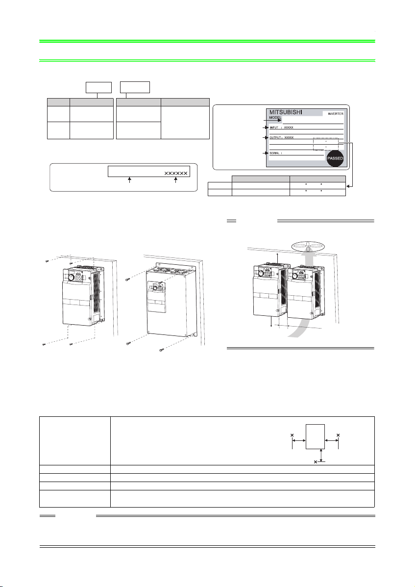
INSTALLATION OF THE INVERTER AND INSTRUCTIONS
)
1
INSTALLATION OF THE INVERTER AND INSTRUCTIONS
• Inverter Model
FR --F740
Symbol Voltage Class
Three-phase
F720
200V class
Three-phase
F740
400V class
00126
00046 to 04750
00023 to 12120
- NA
Symbol Model number
200V class
400V class
Displays
the rated current.
Rating plate
Inverter model
Input rating
Output rating
Serial number
FR-F740-00126-NA
LD (50 C) XXA
SLD (40 C) XXA
Capacity plate
FR-F740-00126-NA
Inverter model
Serial number
Overload Current Rating Surrounding Air Temperature
LD 120% 60s, 150% 3s
SLD 110% 60s, 120% 3s
50 C(122 F)
40 C(104 F)
• Installation of the inverter
Note - Some inverter models may be installed outside an
enclosure. See Appendix 2 for details.
Installation on the enclosure
FR-F720-01250 or less
FR-F740-00620 or less
FR-F720-01540 or more
FR-F740-00770 or more
Fix six positions for the FR-F74004320 to 08660 and fix eight positions
for the FR-F740-09620 to 12120.
CAUTION
When encasing multiple inverters, install them in parallel
as a cooling measure.
10cm(3.94inches)
or more
*2
10cm(3.94inches)
or more
*1 1cm or more for FR-F720-00167 (FR-F740-00083) or less
10cm or more for FR-F720-03160 (FR-F740-01800) or more
*2 20cm or more for FR-F720-03160 (FR-F740-01800) or more
5
c
*2
m(1.97inches) or
mor
e
*
1
• General Precaution
The bus capacitor discharge time is 10 minutes. Before starting wiring or inspection, switch power off, wait for more than 10
minutes, and check for residual voltage between terminal P/+ and N/- with a meter etc., to avoid a hazard of electrical shock.
• Environment
Before installation, check that the environment meets following specifications.
Inverter
Measurement
position
5cm
(1.97inches
5cm
(1.97inches)
LD: -10°C to + 50°C (14°F to 122°F) Maximum (non-
Surrounding Air
Tem pe ra tur e
Ambient humidity
Storage temperature
Ambience
Altitude, vibration
CAUTION
• Install the inverter on a non-combustible wall surface such as metal or concrete.
• Mount the inverter on a strong surface securely and vertically with bolts.
• Provide sufficient clearance distances away from other devices.
• WARNING: HEAT SINK SURFACE MAY BE HOT. TO REDU CE RISK OF BURN - DO NOT TOUCH.
freezing)
SLD (initial setting): -10°C to + 40°C (14°F to 104°F)
Maximum (non-freezing)
5cm
(1.97inches)
Measurement
position
90%RH or less (non-condensing)
-20°C to + 65°C (-4°F to 149°F)
Indoors (No corrosive and flammable gases, oil mist, dust and dirt.)
Below 1000m, 5.9m/s2 or less at 10 to 55Hz (directions of X, Y, Z axes) (2.9m/s2 or less for the FRF740-04320 or more)
1
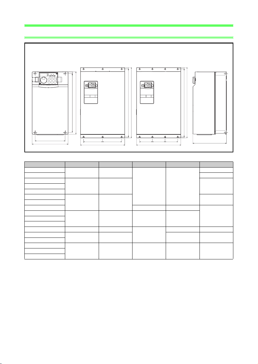
OUTLINE DRAWING
2 OUTLINE DRAWING
FR-F720-00046 to
04750-NA
FR-F740-00023 to
03610-NA
FR-F740-04320 to
08660-NA
FR-F740-09620 to
12120-NA
H
H1
W1
W
W1 W1
W
H
H1
W1 W1 W1
W
H
H1
D
(Unit:mm(inches))
• 200V class
Inverter Model W W1 H H1 D
FR-F720-00046-NA
FR-F720-00077-NA 125 (4.92)
FR-F720-00105-NA
FR-F720-00250-NA
FR-F720-00340-NA
FR-F720-00490-NA
FR-F720-00630-NA 300 (11.81) 285 (11.22)
FR-F720-00770-NA
FR-F720-01250-NA
FR-F720-01540-NA 325 (12.8) 270 (10.63)
FR-F720-01870-NA
FR-F720-02330-NA
FR-F720-03160-NA
110 (4.33) 95 (3.74)
150 (5.91) 125 (4.92) 140 (5.51)FR-F720-00167-NA
220 (8.66) 195 (7.68)
250 (9.84) 230 (9.06) 400 (15.75) 380 (14.96)FR-F720-00930-NA
435 (17.13) 380 (14.96) 525 (20.67) 250 (9.84)
260 (10.24) 245 (9.65)
530 (20.87) 195 (7.68)
550 (21.65)
110 (4.33)
170 (6.69)
190 (7.48)
465 (18.31) 400 (15.75) 740 (29.13) 715 (28.15) 360 (14.17)FR-F720-03800-NA
FR-F720-04750-NA
2

OUTLINE DRAWING
• 400V class
Inverter Model W W1 H H1 D
FR-F740-00023-NA
FR-F740-00038-NA
FR-F740-00052-NA
FR-F740-00083-NA
FR-F740-00126-NA
FR-F740-00170-NA
FR-F740-00250-NA
FR-F740-00310-NA
FR-F740-00380-NA
FR-F740-00470-NA
FR-F740-00620-NA
FR-F740-00770-NA 325 (12.8) 270 (10.63) 550 (21.65) 530 (20.87) 195 (7.68)
FR-F740-00930-NA
FR-F740-01800-NA
FR-F740-02160-NA
FR-F740-02600-NA
FR-F740-03250-NA
FR-F740-03610-NA
FR-F740-04320-NA
FR-F740-04810-NA
FR-F740-05470-NA
FR-F740-06830-NA
FR-F740-07700-NA
FR-F740-08660-NA
FR-F740-09620-NA
FR-F740-12120-NA
150 (5.91) 125 (4.92)
260 (10.24) 245 (9.65)
220 (8.66) 195 (7.68)
300 (11.81) 285 (11.22) 190 (7.48)
250 (9.84) 230 (9.06) 400 (15.75) 380 (14.96) 190 (7.48)
435 (17.13) 380 (14.96) 550 (21.65) 525 (20.67) 250 (9.84)FR-F740-01160-NA
620 (24.41) 595 (23.43) 300 (11.81)
465 (18.31) 400 (15.75)
740 (29.13) 715 (28.15) 360 (14.17)
498 (19.6) 200 (7.87)
1010 (39.76) 984 (38.77) 380 (14.96)
680 (26.77) 300 (11.81)FR-F740-06100-NA
790 (31.1) 315 (12.4) 1330 (52.36) 1300 (51.18)
995 (39.17) 300 (11.81) 1580 (62.2) 1550 (61.02)FR-F740-10940-NA
140 (5.51)
170 (6.69)
440 (17.32)
3
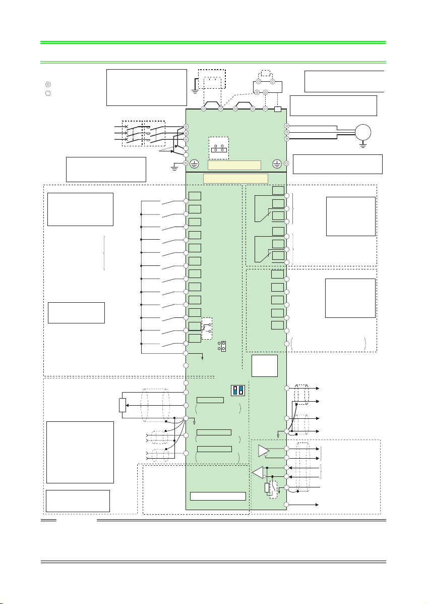
3WIRING
t
u
PX*7
N/-
*8
PU
connector
Terminating
resistor
Resistor unit
*6. A CN8 (for MT-BU5) connector is
(Option)
provided for the FR-F720-03160
Brake unit
(FR-F740-01800) or more.
(Option)
*7.
Do not use PR and PX terminals.
Please do not remove the jumper
connected to terminal PR and PX.
CN8
*6
U
V
W
*8.
The 200V class 00046 and 00077
are not provided with the ON/OFF
connector EMC filter.
C1
B1
Relay output 1
(Fault output)
A1
C2
B2
Relay output 2
A2
RUN
Running
SU
Up to frequency
IPF
Instantaneous
power failure
OL
Overload
FU
Frequency detection
SE
Open collector output common
/source common
Sink
CA
CA
CA
AM
5
TXD+
TXD-
RXD+
RXD-
SG
VCC
Motor
IM
Relay output
Terminal functions
vary with the output
terminal assignment
(Pr. 195, Pr. 196)
Refer to the
Instruction Manual
(applied) chapter4.
Open collector output
Terminal functions
vary with the output
terminal assignment
(Pr. 190 to Pr. 194)
Refer to the
Instruction Manual
(applied) chapter4.
(+)
(+)
(+)
Analog current outp
(0 to 20mADC)
(0 to 20mADC)
(0 to 20mADC)
(-)
(-)
(-)
(+)
Analog signal outpu
(0 to 10VDC)
(-)
RS-485 terminals
Data transmission
Data reception
GND
(Permissible load
5V
current 100mA)
Ground
*1. DC reactor (FR-HEL)
Sink logic
Main circuit terminal
Control circuit terminal
Three-phase AC
power supply
*2. To supply power to the
control circuit separately,
remove the jumper across
R1/L11 and S1/L21.
Control input signals (No voltage input allowed)
Terminal functions vary
with the input terminal
assignment
(Pr. 178 to Pr. 189)
(Refer to the Inst ruction
Manual (applied) chapter4.)
Be sure to connect the DC reactor
supplied with the FR-F720-03160
(FR-F740-01800) or more
When a DC reactor is connected to
the 02330 (FR-F740-01160) or less,
remove the jumper across P1-P/+.
MCCB
Jumper
.
MC
*2
Ground
Forward
rotation
start
Reverse
rotation
start
Start self-holding selection
High speed
Multi-speed
selection
Middle speed
Low speed
Jog mode
Second function selection
*3. AU terminal can be
used as PTC input
terminal.
Terminal 4 input selection
Selection of automatic restart
(Common for external power supply transistor)
Output stop
Reset
(Current input selection)
after instantaneous
power failure
Contact input common
24VDC power supply
Frequency setting signal (Analog)
1/2W1k
*5
3
Ω
1
Auxiliary
input
Terminal
4 input
(Current
input)
2
(+)
(-)
(+)
(-)
Connector
for plug-in option
connection
Frequency setting
potentiometer
*
4. Terminal input specifications
can be changed by analog
input specifications switchover
(Pr. 73, Pr. 267). Set the
voltage/current input switch in
the OFF position to select
voltage input (0 to 5V/0 to
10V) and ON to select current
input (0 to 20mA).
(Refer to the Instruction
Manual (appli ed) chapter4.)
*
5. It is recommended to use
2W1kΩ when the
frequency setting signal is
changed frequently.
CAUTION
• To prevent a malfunction due to noise, keep the signal cables more than 10cm away from the power cables. Also separate
the main circuit wire of the input side and the output side.
• After wiring, wire offcuts must not be left in the inverter.
Wire offcuts can cause an alarm, failure or malfunction. Always keep the inverter clean.
When drilling mounting holes in a control box etc., take care not to allow chips and other foreign matter to enter the inverter.
• Set the voltage/current input switch correctly. Different setting may cause a fault, failure or malfunction.
*1
Ground
Jumper
P1
P/+
R/L1
S/L2
T/L3
ON
R1/L11
S1/L21
OFF
Main circuit
Control circuit
STF
STR
STOP
RH
RM
RL
JOG
RT
MRS
RES
*3
AU
AU
PTC
CS
SD
SOURCE
PC
*4
Voltage/current
10E(+10V)
10(+5V)
5
1
4
input switch
ON
OFF
0 to 5VDC
2
0 to 10VDC
0 to 20mADC
(Analog common)
0 to ±10VDC
0 to ±5VDC
4 to 20mADC
0 to 5VDC
0 to 10VDC
Option connector 1
Jumper
PR*7
EMC filter
ON/OFF
connector
SINK
4
Initial value
selected
Initial
value
selected
Initial
value
selected
2
*
4
*
4
*
4
4
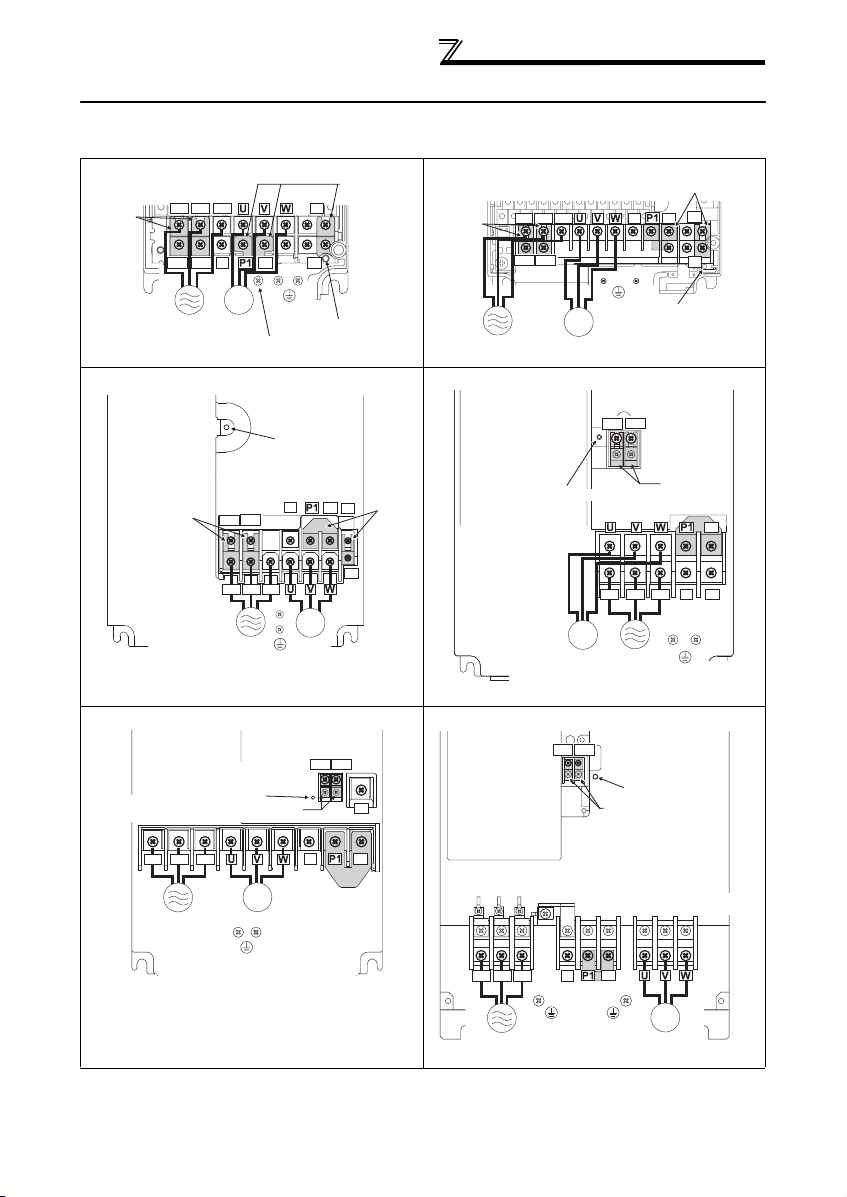
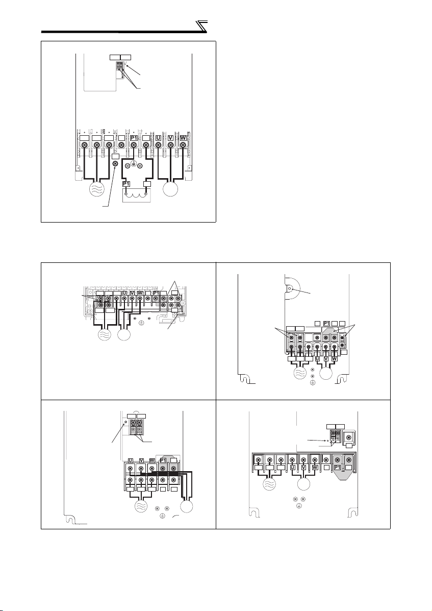
3.1 Main circuit terminal
r
(1) Terminal layout and wiring
200V class
FR-F720-00046, 00077-NA FR-F720-00105 to 00250-NA
Screw size (M4)
R/L1
T/L3
Jumper
S/L2
Jumper
PR
Jumper
Screw size (M4)
R/L1 S/L2 T/L3
WIRING
Jumper
PR
P/+
N/-
R1/L11
S1/L21
Power supply
N/-
IM
Motor
As this is an inside cover fixing screw,
do not remove it.
P/+
Screw size
(M4)
PX
Charge lamp
R1/L11 S1/L21
Power supply
FR-F720-00340, 00490-NA FR-F720-00630-NA
Charge lamp
Charge lamp
Screw size (M5)
Jumper
Screw size
(M5)
**
R1/L11 S1/L21
R/L1 S/L2 T/L3
*
N/-
P/+
PR
Jumpe
PX
*
IM
* Screw size of terminal
R1/L11, S1/L21, PR
and PX is M4.
Power supply
FR-F720-00770 to 01250-NA FR-F720-01540 to 02330-NA
Screw size
(00770:M6, 00930/01250:M8)
Charge lamp
Motor
Screw size (M5)
Screw size (M4)
Jumper
R1/L11 S1/L21
R1/L11 S1/L21
Screw size
(M4)
PR
IM
Motor
IM
Motor
Screw size
(M4)
R1/L11 S1/L21
Screw size
R/L1 S/L2 T/L3
Power supply
Screw size (M5)
Charge lamp
Jumper
PX
Charge lamp
(M4)
Jumper
Jumper
N/-
P/+
PR
R/L1 S/L2 T/L3
Power supply
IM
Motor
Screw size (M6)
N/-
P/+
Jumper
R/L1 S/L2 T/L3
Power
supply
Screw size
(01540:M8, 01870/02330:M10)
N/-
P/+
Jumper
Screw size
(01540:M6,
01870/02330:M8)
IM
Motor
5
WIRING
r
FR-F720-03160 to 04750-NA
Screw size (M4)
R1/L11 S1/L21
Charge lamp
Jumper
Screw size (M12)
P/+
R/L1 S/L2 T/L3
R1/L11 S1/L21
Power
supply
Charge lamp
Screw size (M5)
N/-
Screw size
(M10)
DC reactor
IM
Motor
R1/L11 S1/L21
R/L1 S/L2 T/L3
Power supply
P/+
P/+
N/-
Screw size
(M4)
Screw size
Screw size (M5)
(M4)
Jumper
IM
Motor
Jumper
PR
P/+
PX
Charge lamp
Jumper
P/+
N/-
PR
IM
Motor
Jumper
Screw size
(M4)
Screw size (M6)
R/L1 S/L2 T/L3
Power supply
Power supply
Charge lamp
R/L1 S/L2 T/L3
Power supply
Screw size (M12)
(for option)
400V class
FR-F740-00023 to 00126-NA FR-F740-00170, 00250-NA
Screw size (M4)
Jumper
FR-F740-00310, 00380-NA FR-F740-00470, 00620-NA
R1/L11 S1/L21
R/L1 S/L2 T/L3
Screw size
(M4)
Screw size (M4)
Jumper
IM
Motor
Screw size (M6)
Charge lamp
N/-
IM
Motor
R1/L11 S1/L21
N/-
P/+
PR
PX
Jumper
Jumpe
PR
P/+
6
 Loading...