

Mitsubishi Electric F700, FR-F720, FR-F740 Instruction Manual

INVERTER
INSTRUCTION MANUAL (BASIC)
FR-F720-0.75K to 110K
FR-F740-0.75K to 560K
Thank you for choosing this Mitsubishi Inverter.
This Instruction Manual (basic) is intended for users who "just want to run the inverter".
If you are going to utilize functions and performance, refer to the Instruction Manual (applied) [IB-0600177ENG].
The Instruction Manual (applied) is separately available from where you purchased the inverter or your Mitsubishi
sales representative.
CONTENTS
PRODUCT CHECKING AND PARTS IDENTIFICATION ..............................1
1
INSTALLATION AND WIRING ......................................................................2
2
2.1 Peripheral devices .....................................................................................................3
2.2 Method of removal and reinstallation of the front cover ............................................5
2.3 Installation of the inverter and instructions ................................................................7
2.4 Wiring.........................................................................................................................8
2.5 Connection of stand-alone option units ...................................................................28
2.6 Power-off and magnetic contactor (MC) .................................................................36
2.7 Precautions for use of the inverter ..........................................................................37
2.8 Failsafe of the system which uses the inverter .......................................................39
DRIVE THE MOTOR ....................................................................................40
3
3.1 Step of operation .....................................................................................................40
3.2 Operation panel (FR-DU07) ....................................................................................41
3.3 Overheat protection of the motor by the inverter (Pr. 9) .........................................46
3.4 When the rated motor frequency is 50Hz (Pr. 3) ....................................................47
3.5 Start/stop from the operation panel (PU operation mode) ......................................48
3.6 Start and stop using terminals (External operation) ................................................57
4
ADJUSTMENT .............................................................................................65
4.1 Simple mode parameter list.....................................................................................65
4.2 Increasing the starting torque (Pr. 0).......................................................................66
4.3 Limiting the maximum and minimum output frequency (Pr. 1, Pr. 2)......................67
4.4 Changing acceleration and deceleration time (Pr. 7, Pr. 8) ....................................68
4.5 Energy saving operation (Pr. 60).............................................................................69
4.6 Selection of the operation command and frequency command locations (Pr. 79).71
4.7 Parameter clear, all parameter clear .......................................................................72
4.8 Parameter copy and parameter verification ............................................................73
4.9 Parameter list...........................................................................................................75
TROUBLESHOOTING ...............................................................................102
5
5.1 Reset method of protective function......................................................................102
5.2 List of fault or alarm display...................................................................................103
5.3 Causes and corrective actions ..............................................................................104
5.4 Correspondences between digital and actual characters .....................................115
5.5 Check and clear of the faults history .....................................................................116
5.6 Check first when you have a trouble .....................................................................118
6
PRECAUTIONS FOR MAINTENANCE AND INSPECTION......................125
6.1 Inspection item.......................................................................................................125
SPECIFICATIONS......................................................................................134
7
7.1 Rating.....................................................................................................................134
7.2 Common specifications .........................................................................................136
7.3 Outline dimension drawings ..................................................................................138
7.4 Heatsink protrusion attachment procedure ...........................................................149
700
1
2
3
4
5
6
7
This Instruction Manual (Basic) provides handling information and precautions for use of the equipment.
Please forward this Instruction Manual (Basic) to the end user.
2. Fire Prevention
This section is specifically about safety matters
Do not attempt to install, operate, maintain or inspect the inverter
until you have read through this Instruction Manual (Basic) and
appended documents carefully and can use the equipment
correctly. Do not use the inverter until you have a full knowledge
of the equipment, safety information and instructions. In this
Instruction Manual (Basic), the safety instruction levels are
classified into "WARNING" and "CAUTION".
WARNING
Incorrect handling may cause hazardous
conditions, resulting in death or severe
injury.
CAUTION
Incorrect handling may cause hazardous
conditions, resulting in medium or slight
injury, or may cause only material damage.
CAUTION
The level may even lead to a serious consequence
according to conditions. Both instruction levels must be followed
because these are important to personal safety.
1. Electric Shock Prevention
WARNING
• While power is ON or when the inverter is running, do not open
the front cover. Otherwise you may get an electric shock.
• Do not run the inverter with the front cover or wiring cover
• Inverter must be installed on a nonflammable wall without
holes (so that nobody touches the inverter heatsink on the rear
side, etc.). Mounting it to or near flammable material can cause
a fire.
• If the inverter has become faulty, the inverter power must be
switched OFF. A continuous flow of large current could cause a
fire.
• Do not connect a resistor directly to the DC terminals P/+ and
N/-. Doing so could cause a fire.
3. Injury Prevention
• The voltage applied to each terminal must be the ones
specified in the Instruction Manual. Otherwise burst, damage,
etc. may occur.
• The cables must be connected to the correct terminals.
Otherwise burst, damage, etc. may occur.
• Polarity must be correct. Otherwise burst, damage, etc. may
occur.
• While power is ON or for some time after power-OFF, do not
touch the inverter since the inverter will be extremely hot.
Doing so can cause burns.
CAUTION
CAUTION
removed.
Otherwise you may access the exposed high-voltage terminals
or the charging part of the circuitry and get an electric shock.
• Even if power is off, do not remove the front cover except for
wiring or periodic inspection. You may access the charged
inverter circuits and get an electric shock.
• Before wiring, inspection or switching EMC filter ON/OFF
connector, power must be switched OFF. To confirm that, LED
indication of the operation panel must be checked. (It must be
OFF.) Any person who is involved in wiring, inspection or
switching EMC filter ON/OFF connector shall wait for at least
10 minutes after the power supply has been switched OFF and
check that there are no residual voltage using a tester or the
like. The capacitor is charged with high voltage for some time
after power OFF, and it is dangerous.
• This inverter must be earthed (grounded). Earthing (grounding)
must conform to the requirements of national and local safety
regulations and electrical code (NEC section 250, IEC 536
class 1 and other applicable standards).
A neutral-point earthed (grounded) power supply for 400V
class inverter in compliance with EN standard must be used.
• Any person who is involved in wiring or inspection of this
equipment shall be fully competent to do the work.
• The inverter must be installed before wiring. Otherwise you
may get an electric shock or be injured.
• Setting dial and key operations must be performed with dry
hands to prevent an electric shock. Otherwise you may get an
electric shock.
• Do not subject the cables to scratches, excessive stress,
heavy loads or pinching. Otherwise you may get an electric
shock.
• Do not replace the cooling fan while power is on. It is
dangerous to replace the cooling fan while power is on.
• Do not touch the printed circuit board with wet hands. You may
4. Additional Instructions
Also the following points must be noted to prevent an accidental failure,
injury, electric shock, etc.
(1) Transportation and installation
CAUTION
• The product must be transported in correct method that
corresponds to the weight. Failure to do so may lead to injuries.
• Do not stack the boxes containing inverters higher than the
number recommended.
• The product must be installed to the position where withstands
the weight of the product according to the information in the
Instruction Manual.
• Do not install or operate the inverter if it is damaged or has
parts missing. This can result in breakdowns.
• When carrying the inverter, do not hold it by the front cover or
setting dial; it may fall off or fail.
• Do not stand or rest heavy objects on the product.
• The inverter mounting orientation must be correct.
• Foreign conductive bodies must be prevented to enter the
inverter. That includes screws and metal fragments or other
flammable substance such as oil.
• As the inverter is a precision instrument, do not drop or subject
it to impact.
• The inverter must be used under the following environment:
Otherwise the inverter may be damaged.
Surrounding air
temperature
Ambient humidity 90% RH or less (non-condensing)
Storage temperature -20°C to +65°C
Atmosphere
Environment
Altitude, vibration
-10°C to +50°C (non-freezing)
Indoors (free from corrosive gas, flammable
gas, oil mist, dust and dirt)
Maximum 1000m above sea level for
standard operation. 5.9m/s2 or less at 10 to
55Hz (directions of X, Y, Z axes)
get an electric shock.
• When measuring the main circuit capacitor capacity (Pr. 259
Main circuit capacitor life measuring = "1"), the DC voltage is
applied to the motor for 1s at powering off. Never touch the
*1 Temperature applicable for a short time, e.g. in transit.
*2 2.9m/s
2
or less for the 185K or more.
motor terminal, etc. right after powering off to prevent an
electric shock.
*1
*2
A-1
(2) Wiring
• Do not install a power factor correction capacitor, surge
suppressor or capacitor type filter on the inverter output side.
These devices on the inverter output side may be overheated
or burn out.
• The connection orientation of the output cables U, V, W to the
motor affects the rotation direction of the motor.
(3) Test operation and adjustment
CAUTION
CAUTION
• Before starting operation, each parameter must be confirmed
and adjusted. A failure to do so may cause some machines to
make unexpected motions.
(4) Operation
• Any person must stay away from the equipment when the retry
function is set as it will restart suddenly after trip.
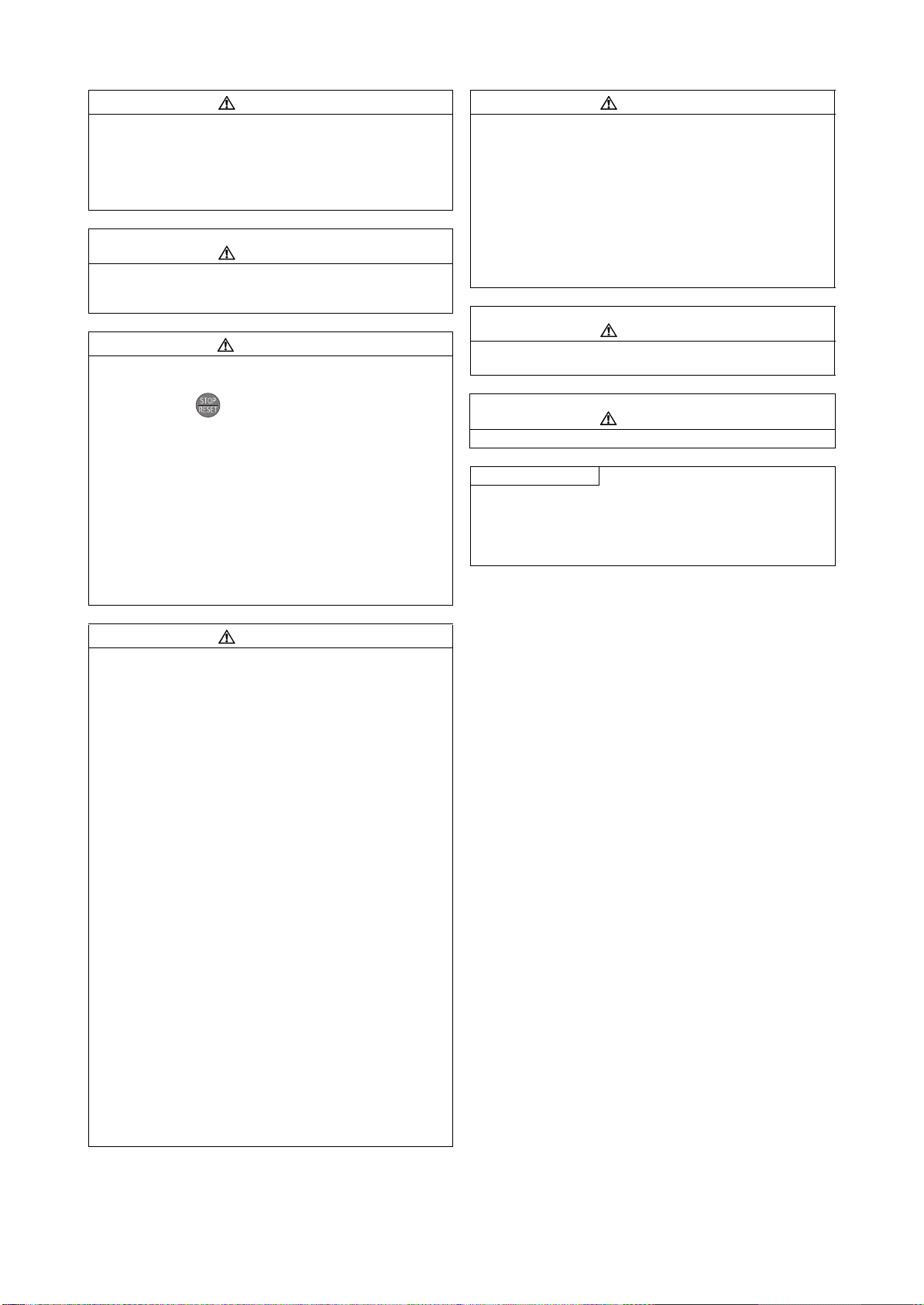
• Since pressing key may not stop output depending on
the function setting status, separate circuit and switch that
make an emergency stop (power OFF, mechanical brake
operation for emergency stop, etc.) must be provided.
• OFF status of the start signal must be confirmed before
resetting the inverter fault. Resetting inverter alarm with the
start signal ON restarts the motor suddenly.
• The inverter must be used for three-phase induction motors.
Connection of any other electrical equipment to the inverter
output may damage the equipment.
• Do not modify the equipment.
• Do not perform parts removal which is not instructed in this
manual. Doing so may lead to fault or damage of the inverter.
WARNING
(5) Emergency stop
• A safety backup such as an emergency brake must be
provided to prevent hazardous condition to the machine and
equipment in case of inverter failure.
• When the breaker on the inverter input side trips, the wiring
must be checked for fault (short circuit), and internal parts of
the inverter for a damage, etc. The cause of the trip must be
identified and removed before turning ON the power of the
breaker.
• When any protective function is activated, appropriate
corrective action must be taken, and the inverter must be reset
before resuming operation.
(6) Maintenance, inspection and parts replacement
CAUTION
CAUTION
• Do not carry out a megger (insulation resistance) test on the
control circuit of the inverter. It will cause a failure.
(7) Disposing of the inverter
CAUTION
• The inverter must be treated as industrial waste.
General instructions
Many of the diagrams and drawings in this Instruction Manual
(basic) show the inverter without a cover or partially open for
explanation. Never operate the inverter in this manner. The
cover must be always reinstalled and the instruction in this
Instruction Manual (basic) must be followed when operating the
inverter.
CAUTION
• The electronic thermal relay function does not guarantee
protection of the motor from overheating. It is recommended to
install both an external thermal and PTC thermistor for
overheat protection.
• Do not use a magnetic contactor on the inverter input for
frequent starting/stopping of the inverter. Otherwise the life of
the inverter decreases.
• The effect of electromagnetic interference must be reduced by
using a noise filter or by other means. Otherwise nearby
electronic equipment may be affected.
• Appropriate measures must be taken to suppress harmonics.
Otherwise power supply harmonics from the inverter may heat/
damage the power factor correction capacitor and generator.
• When driving a 400V class motor by the inverter, the motor
must be an insulation-enhanced motor or measures must be
taken to suppress surge voltage. Surge voltage attributable to
the wiring constants may occur at the motor terminals,
deteriorating the insulation of the motor.
• When parameter clear or all parameter clear is performed, the
required parameters must be set again before starting
operations because all parameters return to the initial value.
• The inverter can be easily set for high-speed operation. Before
changing its setting, the performances of the motor and
machine must be fully examined.
• Stop status cannot be hold by the inverter's brake function. In
addition to the inverter's brake function, a holding device must
be installed to ensure safety.
• Before running an inverter which had been stored for a long
period, inspection and test operation must be performed.
• For prevention of damage due to static electricity, nearby metal
must be touched before touching this product to eliminate
static electricity from your body.
A-2

— CONTENTS —
1 PRODUCT CHECKING AND PARTS IDENTIFICATION 1
2 INSTALLATION AND WIRING 2
2.1 Peripheral devices...................................................................................................... 3
2.2 Method of removal and reinstallation of the front cover............................................. 5
2.3 Installation of the inverter and instructions.................................................................7
2.4 Wiring.......................................................................................................................... 8
2.4.1 Terminal connection diagram .................................................................................................... 8
2.4.2 EMC filter ................................................................................................................................... 9
2.4.3 Specification of main circuit terminal ....................................................................................... 10
2.4.4 Terminal arrangement of the main circuit terminal, power supply and the motor wiring ......... 10
2.4.5 Control circuit terminals ........................................................................................................... 19
2.4.6 Changing the control logic ....................................................................................................... 22
2.4.7 Wiring of control circuit ............................................................................................................ 24
2.4.8 When connecting the operation panel using a connection cable ............................................ 26
2.4.9 RS-485 terminal block ............................................................................................................. 27
2.4.10 Communication operation........................................................................................................ 27
2.5 Connection of stand-alone option units.................................................................... 28
2.5.1 Connection of the brake unit (FR-BU2) ................................................................................... 28
2.5.2 Connection of the brake unit (FR-BU/MT-BU5) ....................................................................... 30
2.5.3 Connection of the brake unit (BU type) ................................................................................... 32
2.5.4 Connection of the high power factor converter (FR-HC/MT-HC)............................................. 32
2.5.5 Connection of the power regeneration common converter (FR-CV)(55K or less) ................... 34
2.5.6 Connection of the power regeneration converter (MT-RC) (75K or more) .............................. 35
2.5.7 Connection of the power factor improving DC reactor (FR-HEL) ............................................ 35
CONTENTS
2.6 Power-off and magnetic contactor (MC) ..................................................................36
2.7 Precautions for use of the inverter ........................................................................... 37
2.8 Failsafe of the system which uses the inverter ........................................................39
3 DRIVE THE MOTOR 40
3.1 Step of operation......................................................................................................40
3.2 Operation panel (FR-DU07)..................................................................................... 41
3.2.1 Parts of the operation panel (FR-DU07) .................................................................................. 41
3.2.2 Basic operation (factory setting) .............................................................................................. 42
3.2.3 Operation lock (Press [MODE] for an extended time (2s)) ...................................................... 43
3.2.4 Monitoring of output current and output voltage ...................................................................... 44
3.2.5 First priority monitor ................................................................................................................. 44
3.2.6 Setting dial push ...................................................................................................................... 44
3.2.7 Changing the parameter setting value..................................................................................... 45
3.3 Overheat protection of the motor by the inverter (Pr. 9) .......................................... 46
3.4 When the rated motor frequency is 50Hz (Pr. 3) .....................................................47
3.5 Start/stop from the operation panel (PU operation mode).......................................48
3.5.1 Setting the set frequency to operate (example: performing operation at 30Hz) ...................... 48
I

3.5.2 Using the setting dial like a potentiometer at the operation. .................................................... 50
3.5.3 Setting the frequency by switches (three-speed setting) ......................................................... 51
3.5.4 Setting the frequency by analog input (voltage input) ............................................................. 53
3.5.5 Setting the frequency by analog input (current input) .............................................................. 55
3.6 Start and stop using terminals (External operation).................................................57
3.6.1 Setting the frequency by the operation panel (Pr. 79 = 3) ....................................................... 57
3.6.2 Setting the frequency by switches (three-speed setting) (Pr. 4 to Pr. 6) ................................. 59
3.6.3 Setting the frequency by analog input (voltage input) ............................................................. 61
3.6.4 Changing the output frequency (60Hz, initial value) at the maximum voltage
input (5V, initial value) ............................................................................................................ 62
3.6.5 Setting the frequency by analog input (current input) .............................................................. 63
3.6.6 Changing the output frequency (60Hz, initial value) at the maximum current input
(at 20mA, initial value) ............................................................................................................. 64
4 ADJUSTMENT 65
4.1 Simple mode parameter list .....................................................................................65
4.2 Increasing the starting torque (Pr. 0)........................................................................66
4.3 Limiting the maximum and minimum output frequency (Pr. 1, Pr. 2) ......................67
4.4 Changing acceleration and deceleration time (Pr. 7, Pr. 8)..................................... 68
4.5 Energy saving operation (Pr. 60) ............................................................................. 69
4.5.1 Energy saving operation mode (setting "4") ............................................................................ 69
4.5.2 Optimum excitation control mode (setting "9")......................................................................... 69
4.6 Selection of the operation command and frequency command locations (Pr. 79).. 71
4.7 Parameter clear, all parameter clear.................................................................... 72
4.8 Parameter copy and parameter verification......................................................... 73
4.8.1 Parameter copy ....................................................................................................................... 73
4.8.2 Parameter verification.............................................................................................................. 74
4.9 Parameter list.......................................................................................................75
4.9.1 List of parameters classified by the purpose ........................................................................... 75
4.9.2 Display of the extended parameters ........................................................................................ 77
4.9.3 Parameter list .......................................................................................................................... 78
5 TROUBLESHOOTING 102
5.1 Reset method of protective function.......................................................................102
5.2 List of fault or alarm display....................................................................................103
5.3 Causes and corrective actions ...............................................................................104
5.4 Correspondences between digital and actual characters......................................115
5.5 Check and clear of the faults history.................................................................. 116
5.6 Check first when you have a trouble......................................................................118
5.6.1 Motor does not start............................................................................................................... 118
5.6.2 Motor or machine is making abnormal acoustic noise........................................................... 120
5.6.3 Inverter generates abnormal noise........................................................................................ 120
5.6.4 Motor generates heat abnormally.......................................................................................... 120
5.6.5 Motor rotates in the opposite direction .................................................................................. 121
II

5.6.6 Speed greatly differs from the setting .................................................................................... 121
5.6.7 Acceleration/deceleration is not smooth ................................................................................ 121
5.6.8 Speed varies during operation............................................................................................... 122
5.6.9 Operation mode is not changed properly .............................................................................. 122
5.6.10 Operation panel (FR-DU07) display is not operating............................................................. 123
5.6.11 Motor current is too large....................................................................................................... 123
5.6.12 Speed does not accelerate .................................................................................................... 124
5.6.13 Unable to write parameter setting.......................................................................................... 124
5.6.14 Power lamp is not lit .............................................................................................................. 124
6 PRECAUTIONS FOR MAINTENANCE AND INSPECTION 125
6.1 Inspection item ....................................................................................................... 125
6.1.1 Daily inspection ..................................................................................................................... 125
6.1.2 Periodic inspection ................................................................................................................ 125
6.1.3 Daily and periodic inspection................................................................................................. 126
6.1.4 Display of the life of the inverter parts ................................................................................... 127
6.1.5 Cleaning ................................................................................................................................ 129
6.1.6 Replacement of parts ............................................................................................................ 129
6.1.7 Inverter replacement.............................................................................................................. 133
CONTENTS
7 SPECIFICATIONS 134
7.1 Rating .....................................................................................................................134
7.2 Common specifications .......................................................................................... 136
7.3 Outline dimension drawings ...................................................................................138
7.3.1 Inverter outline dimension drawings ...................................................................................... 138
7.4 Heatsink protrusion attachment procedure............................................................149
7.4.1 When using a heatsink protrusion attachment (FR-A7CN) ................................................... 149
7.4.2 Protrusion of heatsink of the FR-F740-185K or more............................................................ 149
APPENDICES 151
Appendix 1 For customers who are replacing the conventional model
with this inverter ..................................................................................... 151
Appendix 1-1 Replacement of the FR-F500 series ......................................................................... 151
Appendix 1-2 Replacement of the FR-A100 <EXCELENT> series ................................................. 152
Appendix 2 Instructions for UL and cUL compliance ............................................... 153
Appendix 3 Instructions for compliance with the EU Directives ............................... 155
III

<Abbreviations>
DU: Operation panel (FR-DU07)
PU: Operation panel(FR-DU07) and parameter unit (FR-PU04/FR-PU07)
Inverter: Mitsubishi inverter FR-F700 series
FR-F700: Mitsubishi inverter FR-F700 series
Pr.: Parameter Number
PU operation: Operation using the PU (FR-DU07/FR-PU04/FR-PU07).
External operation: Operation using the control circuit signals
Combined operation: Combined operation using the PU (FR-DU07/FR-PU04/FR-PU07) and external operation
Standard motor: SF-JR
Constant-torque motor: SF-HRCA
<Trademarks>
ONWORKS
L
®
is registered trademarks of Echelon Corporation in the U.S.A. and other countries.
DeviceNet is a registered trademark of ODVA (Open DeviceNet Vender Association, Inc.).
Company and product names herein are the trademarks and registered trademarks of their respective owners.
IV
1
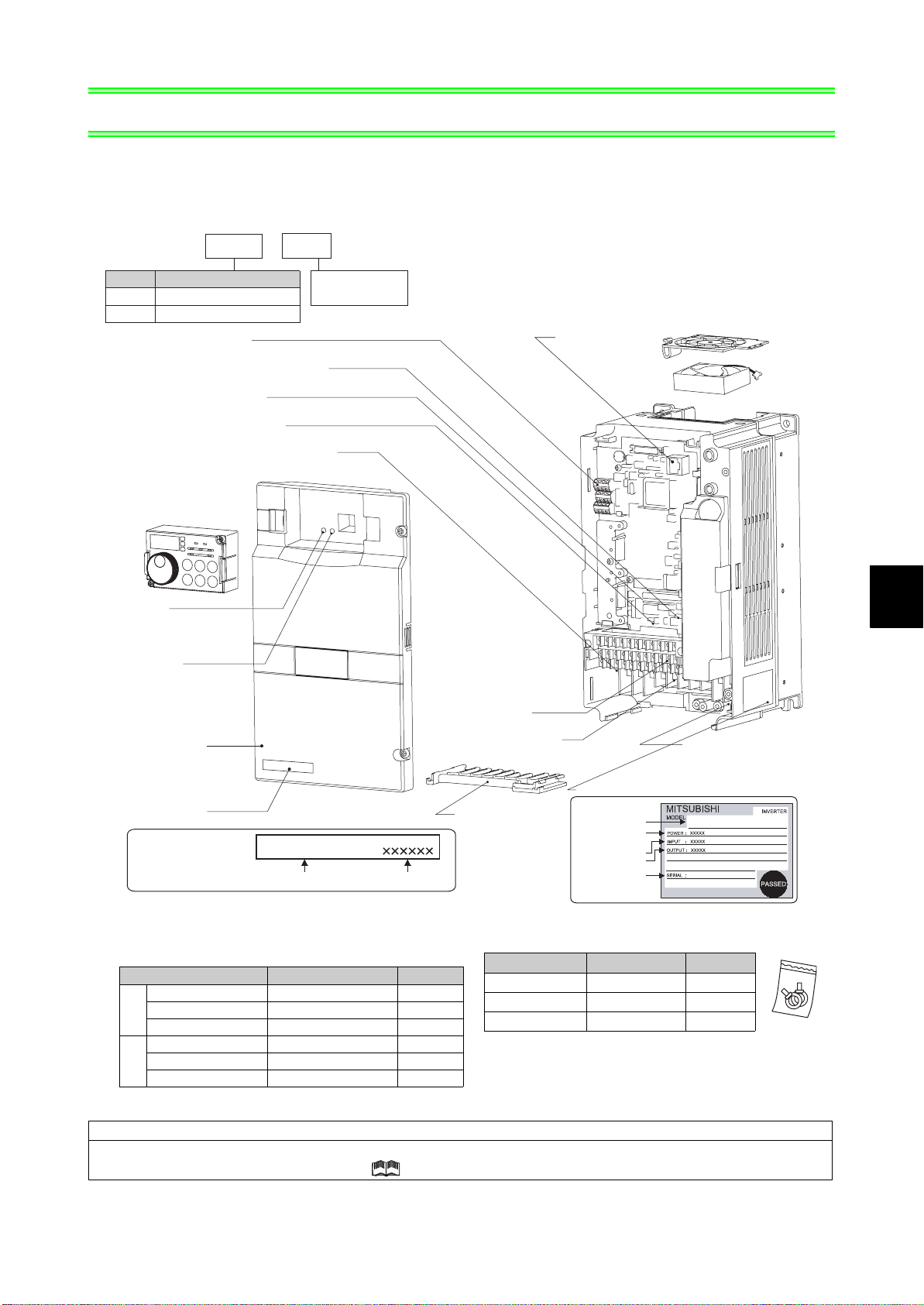
PRODUCT CHECKING AND PARTS IDENTIFICATION
Unpack the inverter and check the capacity plate on the front cover and the rating plate on the inverter side face to
ensure that the product agrees with your order and the inverter is intact.
• Inverter Model
FR --F740
Symbol
F720
F740
Connector for plug-in option connection
(Refer to the instruction manual of options.)
Voltage/current input switch
(Refer to page 8)
Operation panel (FR-DU07)
(Refer to page 5)
Power lamp
Lit when the control circuit
(R1/L11, S1/L21) is supplied
with power.
Alarm lamp
Lit when the inverter is
in the alarm status
(fault).
Voltage Class
Three-phase 200V class
Three-phase 400V class
RS-485 terminals
(Refer to page 27)
AU/PTC switchover switch
(Refer to the chapter 4 of the Instruction Manual (applied).)
EMC filter ON/OFF connector
(Refer to page 9)
Front cover
(Refer to page 5)
Capacity plate
Capacity plate
5.5
Indicate inverter
capacity (kW)
FR-F740-5.5K
Inverter model
K
Serial number
Control circuit
terminal block
(Refer to page 10)
Main circuit terminal block
(Refer to page 19)
Combed shaped
wiring cover
(Refer to page 13)
PU connector
(Refer to page 26)
Rating plate
Rating plate
Inverter model
Applied motor
capacity
Input rating
Output rating
Serial number
Cooling fan
(Refer to page 130)
Charge lamp
Lit when power is
supplied to the main
(Refer to page 10)
circuit
FR-F740-5.5K
1
• Accessory
· Fan cover fixing screws (30K or less)
(Refer to page 155)
Capacity Screw Size (mm) Number
2.2K to 5.5K M3 × 35 1
7.5K to 15K M4 × 40 2
200V
18.5K to 30K M4 × 50 1
· DC reactor supplied (75K or more)
· Eyebolt for hanging the inverter (37K to 315K)
Capacity Eyebolt Size Number
37K M8 2
45K to 160K M10 2
185K to 315K M12 2
3.7K, 5.5K M3 × 35 1
7.5K to 18.5K M4 × 40 2
400V
22K, 30K M4 × 50 1
Harmonic suppression guideline
All models of General-purpose inverters used by specific consumers are covered by "Harmonic suppression guideline for consumers
who receive high voltage or special high voltage". ( For further details, refer to the chapter 3 of the instruction manual (applied) .)
PRODUCT CHECKING AND PARTS IDENTIFICATION
1
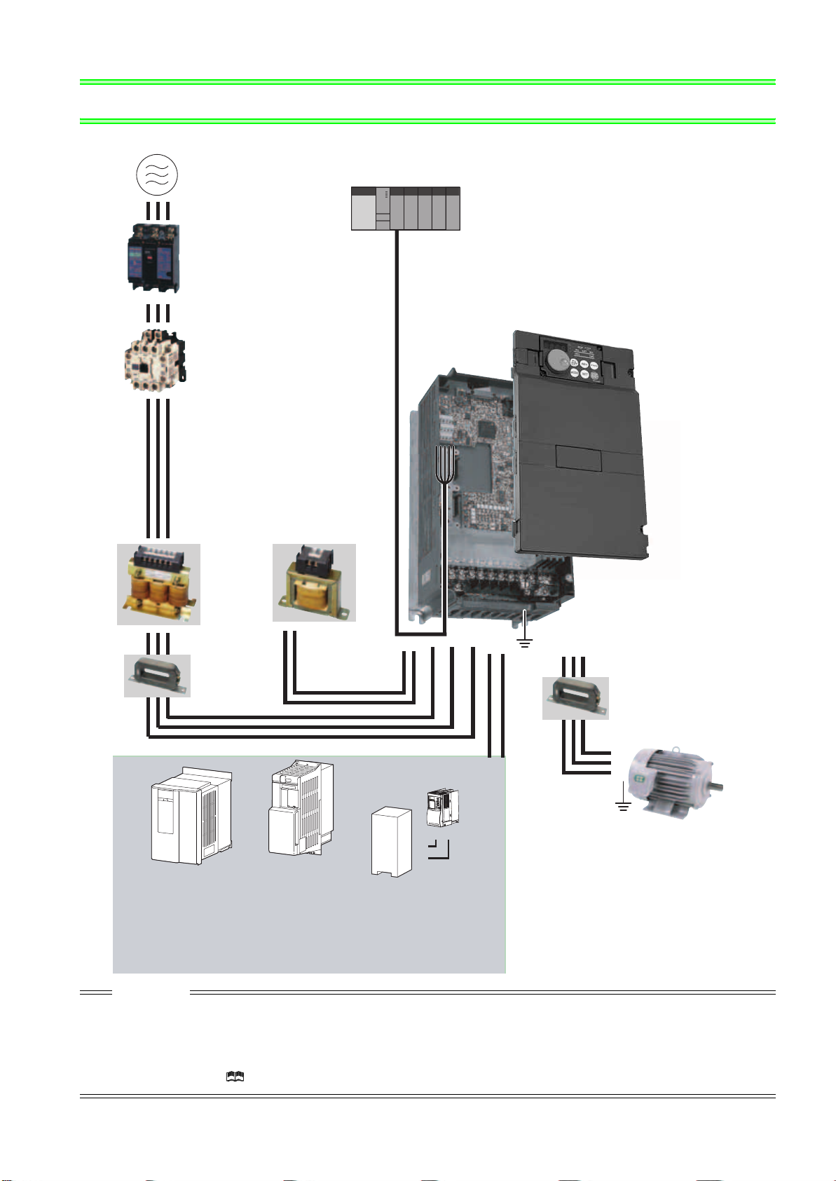
2 INSTALLATION AND WIRING
Three-phase AC power supply
Use within the permissible power supply
specifications of the inverter.
(Refer to page 134)
Programmable controller
Moulded case circuit
breaker (MCCB)
or earth leakage circuit
breaker (ELB), fuse
The breaker must be selected carefully since
an in-rush current flows in the inverter at
power on.
(Refer to page 3)
Magnetic contactor(MC)
Install the magnetic contactor to ensure safety.
Do not use this magnetic contactor to start and
stop the inverter.
Doing so will cause the inverter life to be shorten.
(Refer to page 3)
Reactor (FR-HAL, FR-HEL)
Reactors (option) should be used when power
harmonics measures are taken, the power factor is
to be improved or the inverter is installed near a
large power supply system (1000kVA or more). The
inverter may be damaged if you do not use reactors.
Select the reactor according to the model.
For the 55K or less, remove the jumpers across
terminals P/+-P1 to connect to the DC reactor.
(Refer to the chapter 2 of the Instruction
Manual (applied) .)
RS-485 terminal block
The inverter can be
connected with computers
such as programmable
controller.
It supports Mitsubishi inverter
protocol and Modbus-RTU
(binary) protocol.
Inverter
(FR-F700)
The life of the inverter is influenced by surrounding
air temperature. The surrounding air temperature
should be as low as possible within the permissible
range. Especially when mounting the inverter
inside an enclosure, take cautions of the
surrounding air temperature. (Refer to page 7)
Wrong wiring might lead to damage of the inverter.
The control signal lines must be kept fully away
from the main circuit to protect them from
noise.(Refer to page 8)
Refer to page 9 for the built-in EMC filter.
AC reactor
(FR-HAL)
EMC filter
(ferrite core)
(FR-BLF)
The 55K or less
has a built-in common
mode choke.
DC reactor
(FR-HEL)
For the 75K or more, a DC
reactor is supplied.
Always install the reactor.
P/+
P1
R/L1 S/L2 T/L3
N/-P/+
Earth
(Ground)
UVW
(ferrite core)
(FR-BSF01, FR-BLF)
Install an EMC filter (ferrite
core) to reduce the
electromagnetic noise
generated from the inverter.
Effective in the range from
about 1MHz to 10MHz.
A wire should be wound four
turns at a maximum.
Motor
Brake unit
EMC filter
(FR-BU2, FR-BU
*1, MT-BU5*2)
Earth
(Ground)
PR
High power factor
converter
*1, MT-HC*2)
(FR-HC
Power supply harmonics
can be greatly suppressed.
Install this as required.
*1 Compatible with the 55K or less.
*2 Compatible with the 75K or more.
Power regeneration
common converter
*1)
(FR-CV
Power regeneration
converter (MT-RC
Greater braking capability
is obtained.
Install this as required.
*2)
P/+
P/+
PR
Resistor unit
*1, MT-BR5*2)
(FR-BR
The regeneration braking
capability of the inverter can be
exhibited fully.
Install this as required.
Devices connected to the output
Do not install a power factor correction capacitor,
surge suppressor or EMC filter (capacitor) on the
output side of the inverter.
When installing a moulded case circuit breaker on the
output side of the inverter, contact each manufacturer
for selection of the moulded case circuit breaker.
Earth (Ground)
To prevent an electric shock, always earth
(ground) the motor and inverter.
CAUTION
· Do not install a power factor correction capacitor, surge suppressor or capacitor type filter on the inverter output side. This will
cause the inverter to trip or the capacitor, and surge suppressor to be damaged. If any of the above devices are connected,
immediately remove them.
· Electromagnetic wave interference
The input/output (main circuit) of the inverter includes high frequency components, which may interfere with the communication
devices (such as AM radios) used near the inverter. In this case, set the EMC filter valid to minimize interference.
(Refer to the chapter 2 of the Instruction Manual (applied).)
· Refer to the instruction manual of each option and peripheral devices for details of peripheral devices.
2
Peripheral devices
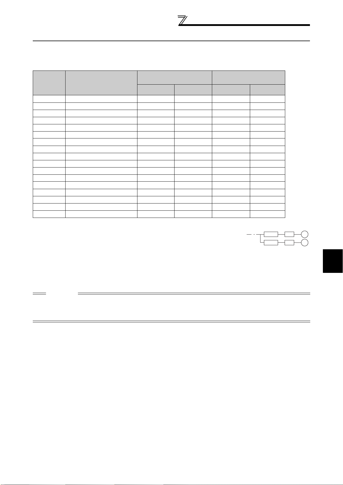
2.1 Peripheral devices
Check the inverter model of the inverter you purchased. Appropriate peripheral devices must be selected according
to the capacity. Refer to the following list and prepare appropriate peripheral devices:
200V class
Motor
Output (kW)
*1
Applicable Inverter Model
Breaker Selection*2
Without reactor
connection
With reactor
connection
0.75 FR-F720-0.75K 30AF 10A 30AF 10A S-N10 S-N10
1.5 FR-F720-1.5K 30AF 15A 30AF 15A S-N10 S-N10
2.2 FR-F720-2.2K 30AF 20A 30AF 15A S-N10 S-N10
3.7 FR-F720-3.7K 30AF 30A 30AF 30A S-N20, S-N21 S-N10
5.5 FR-F720-5.5K 50AF 50A 50AF 40A S-N25 S-N20, S-N21
7.5 FR-F720-7.5K 100AF 60A 50AF 50A S-N25 S-N25
11 FR-F720-11K 100AF 75A 100AF 75A S-N35 S-N35
15 FR-F720-15K 225AF 125A 100AF 100A S-N50 S-N50
18.5 FR-F720-18.5K 225AF 150A 225AF 125A S-N65 S-N50
22 FR-F720-22K 225AF 175A 225AF 150A S-N80 S-N65
30 FR-F720-30K 225AF 225A 225AF 175A S-N95 S-N80
37 FR-F720-37K 400AF 250A 225AF 225A S-N150 S-N125
45 FR-F720-45K 400AF 300A 400AF 300A S-N180 S-N150
55 FR-F720-55K 400AF 400A 400AF 350A S-N220 S-N180
75 FR-F720-75K ⎯ 400AF 400A ⎯
90 FR-F720-90K ⎯ 400AF 400A ⎯
110 FR-F720-110K ⎯ 600AF 500A ⎯
*1 Selections for use of the Mitsubishi 4-pole standard motor with power supply voltage of 200VAC 50Hz.
*2 Select the MCCB according to the power supply capacity.
Install one MCCB per inverter.
For using commercial-power supply operation, select a breaker with capacity which allows the motor to be
directly power supplied.
For the use in the United States or Canada, provide the appropriate UL and cUL listed Class RK5 or Class
L type fuse or UL 489 molded case circuit breaker (MCCB) that is suitable for branch circuit protection.
(Refer to page 153.)
*3 Magnetic contactor is selected based on the AC-1 class. The electrical durability of magnetic contactor is 500,000 times. When the magnetic
contactor is used for emergency stop during motor driving, the electrical durability is 25 times.
When using the MC for emergency stop during motor driving or using on the motor side during commercial-power supply operation, select the
MC with class AC-3 rated current for the motor rated current.
Input Side Magnetic
Contactor
Without reactor
connection
S-N300
S-N300
S-N400
*3
With reactor
connection
MCCB INV
MCCB INV
IM
IM
2
CAUTION
⋅ When the inverter capacity is larger than the motor capacity, select an MCCB and a magnetic contactor according to the
inverter model and cable and reactor according to the motor output.
⋅ When the breaker on the inverter primary side trips, check for the wiring fault (short circuit), damage to internal parts of the
inverter, etc. Identify the cause of the trip, then remove the cause and power on the breaker.
INSTALLATION AND WIRING
3
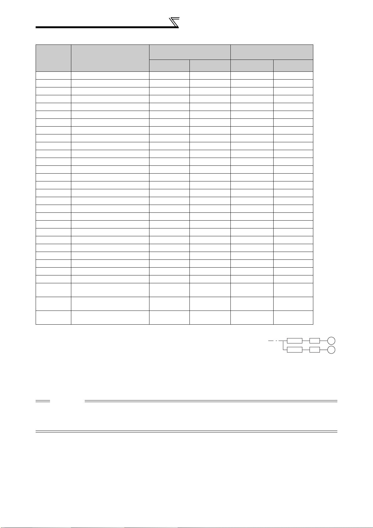
Peripheral devices
400V class
Motor
Output
(kW)
*1
Applicable Inverter Model
Breaker Selection*2
Without reactor
connection
With reactor
connection
0.75 FR-F740-0.75K 30AF 5A 30AF 5A S-N10 S-N10
1.5 FR-F740-1.5K 30AF 10A 30AF 10A S-N10 S-N10
2.2 FR-F740-2.2K 30AF 10A 30AF 10A S-N10 S-N10
3.7 FR-F740-3.7K 30AF 20A 30AF 15A S-N10 S-N10
5.5 FR-F740-5.5K 30AF 30A 30AF 20A S-N20, S-N21 S-N11, S-N12
7.5 FR-F740-7.5K 30AF 30A 30AF 30A S-N20, S-N21 S-N20, S-N21
11 FR-F740-11K 50AF 50A 50AF 40A S-N20, S-N21 S-N20, S-N21
15 FR-F740-15K 100AF 60A 50AF 50A S-N25 S-N20, S-N21
18.5 FR-F740-18.5K 100AF 75A 100AF 60A S-N25 S-N25
22 FR-F740-22K 100AF 100A 100AF 75A S-N35 S-N25
30 FR-F740-30K 225AF 125A 100AF 100A S-N50 S-N50
37 FR-F740-37K 225AF 150A 225AF 125A S-N65 S-N50
45 FR-F740-45K 225AF 175A 225AF 150A S-N80 S-N65
55 FR-F740-55K 225AF 200A 225AF 175A S-N80 S-N80
75 FR-F740-75K ⎯ 225AF 225A ⎯ S-N95
90 FR-F740-90K ⎯ 225AF 225A ⎯ S-N150
110 FR-F740-110K ⎯ 225AF 225A ⎯ S-N180
132 FR-F740-132K ⎯ 400AF 400A ⎯ S-N220
150 FR-F740-160K ⎯ 400AF 400A ⎯ S-N300
160 FR-F740-160K ⎯ 400AF 400A ⎯ S-N300
185 FR-F740-185K ⎯ 400AF 400A ⎯ S-N300
220 FR-F740-220K ⎯ 600AF 500A ⎯ S-N400
250 FR-F740-250K ⎯ 600AF 600A ⎯ S-N600
280 FR-F740-280K ⎯ 600AF 600A ⎯ S-N600
315 FR-F740-315K ⎯ 800AF 700A ⎯ S-N600
355 FR-F740-355K ⎯ 800AF 800A ⎯ S-N600
400 FR-F740-400K ⎯ 1000AF 900A ⎯ S-N800
450 FR-F740-450K ⎯ 1000AF 1000A ⎯
500 FR-F740-500K ⎯ 1200AF 1200A ⎯
560 FR-F740-560K ⎯ 1600AF 1500A ⎯
*1 Selections for use of the Mitsubishi 4-pole standard motor with power supply voltage of 400VAC 50Hz.
*2 Select the MCCB according to the power supply capacity.
Install one MCCB per inverter.
For using commercial-power supply operation, select a breaker with capacity which allows the motor to be
directly power supplied.
For the use in the United States or Canada, provide the appropriate UL and cUL listed Class RK5 or Class
L type fuse or UL 489 molded case circuit breaker (MCCB) that is suitable for branch circuit protection.
(Refer to page 153.)
*3 Magnetic contactor is selected based on the AC-1 class. The electrical durability of magnetic contactor is 500,000 times. When the magnetic
contactor is used for emergency stop during motor driving, the electrical durability is 25 times.
When using the MC for emergency stop during motor driving or using on the motor side during commercial-power supply operation, select the
MC with class AC-3 rated current for the motor rated current.
CAUTION
⋅ When the inverter capacity is larger than the motor capacity, select an MCCB and a magnetic contactor according to the
inverter model and cable and reactor according to the motor output.
⋅ When the breaker on the inverter primary side trips, check for the wiring fault (short circuit), damage to internal parts of the
inverter, etc. Identify the cause of the trip, then remove the cause and power on the breaker.
Input Side Magnetic
Contactor
Without reactor
connection
1000A
Rated product
1000A
Rated product
1200A
Rated product
*3
With reactor
connection
MCCB INV
MCCB INV
IM
IM
4
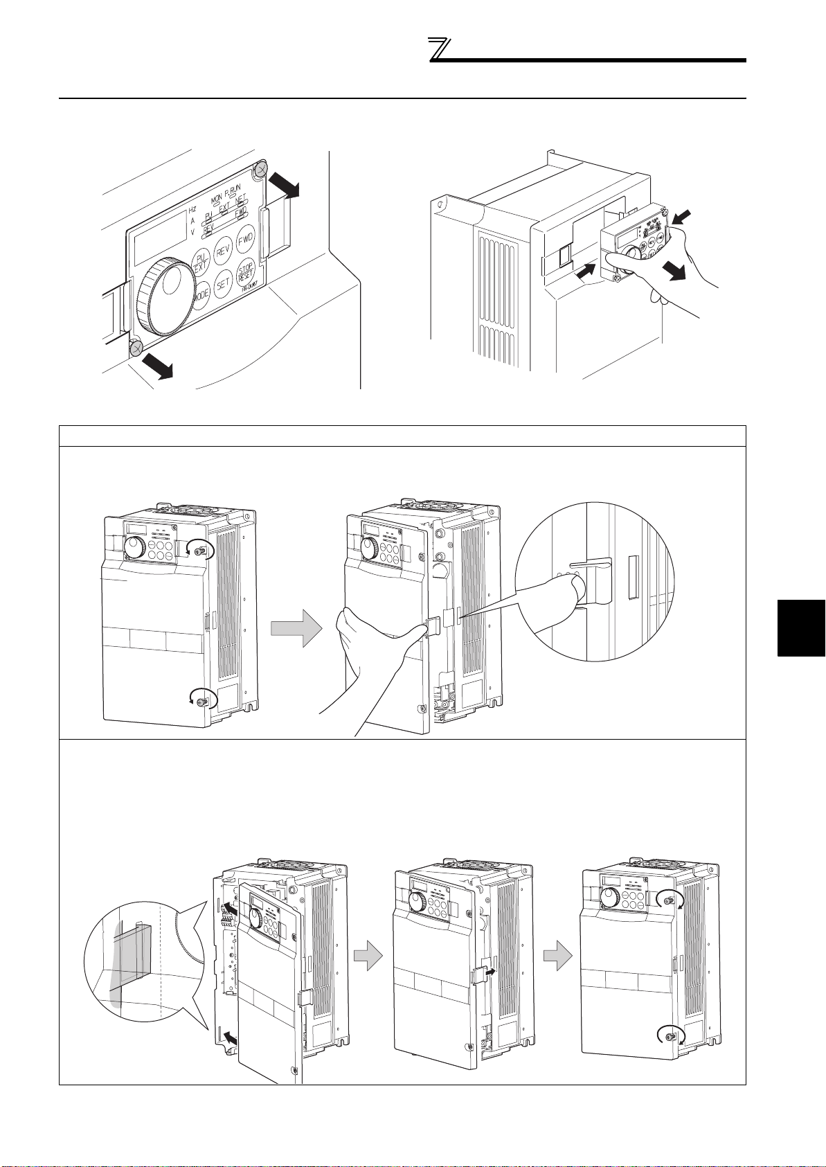
Method of removal and reinstallation of the
front cover
2.2 Method of removal and reinstallation of the front cover
•Removal of the operation panel
1) Loosen the two screws on the operation panel.
(These screws cannot be removed.)
When reinstalling the operation panel, insert it straight to reinstall securely and tighten the fixed screws of the
operation panel.
2) Push the left and right hooks of the operation panel
and pull the operation panel toward you to remove.
FR-F720-30K or less, FR-F740-30K or less
•
Removal
1) Loosen the installation screws of the
2) Pull the front cover toward you to remove by pushing an
front cover.
Front cover
•Reinstallation
1) Insert the two fixed hooks on the left side of
the front cover into the sockets of the
inverter.
installation hook using left fixed hooks as supports.
Front cover
Installation hook
2) Using the fixed hooks as supports,
securely press the front cover
against the inverter.
(Although installation can be done
with the operation panel mounted,
make sure that a connector is
securely fixed.)
3) Tighten the installation
screws and fix the front
cover.
2
Front cover
Front cover
INSTALLATION AND WIRING
Front cover
5
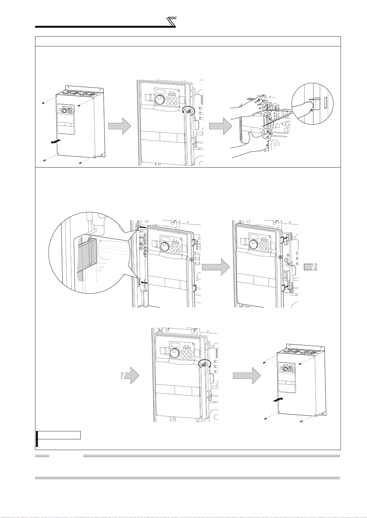
Method of removal and reinstallation of the
front cover
FR-F720-37K or more, FR-F740-37K or more
•
Removal
1) Remove installation screws on
the front cover 1 to remove the
front cover 1.
Front cover 1
•Reinstallation
1) Insert the two fixed hooks on the left side of the
front cover 2 into the sockets of the inverter.
2) Loosen the installation
screws of the front cover 2.
Front cover 2
3) Pull the front cover 2 toward you to
remove by pushing an installation
hook on the right side using left
fixed hooks as supports.
Installation hook
2) Using the fixed hooks as supports, securely
press the front cover 2 against the inverter.
(Although installation can be done with the
operation panel mounted, make sure that a
connector is securely fixed.)
Front cover 2 Front cover 2
3) Fix the front cover 2 with the
installation screws.
Front cover 2
4) Fix the front cover 1 with the
installation screws.
Front cover 1
REMARKS
⋅ For the FR-F740-185K or more, the front cover 1 is separated into two parts.
CAUTION
1. Fully make sure that the front cover has been reinstalled securely. Always tighten the installation screws of the front cover.
2. The same serial number is printed on the capacity plate of the front cover and the rating plate of the inverter. Before reinstalling the
front cover, check the serial numbers to ensure that the cover removed is reinstalled to the inverter from where it was removed.
6
Installation of the inverter and instructions
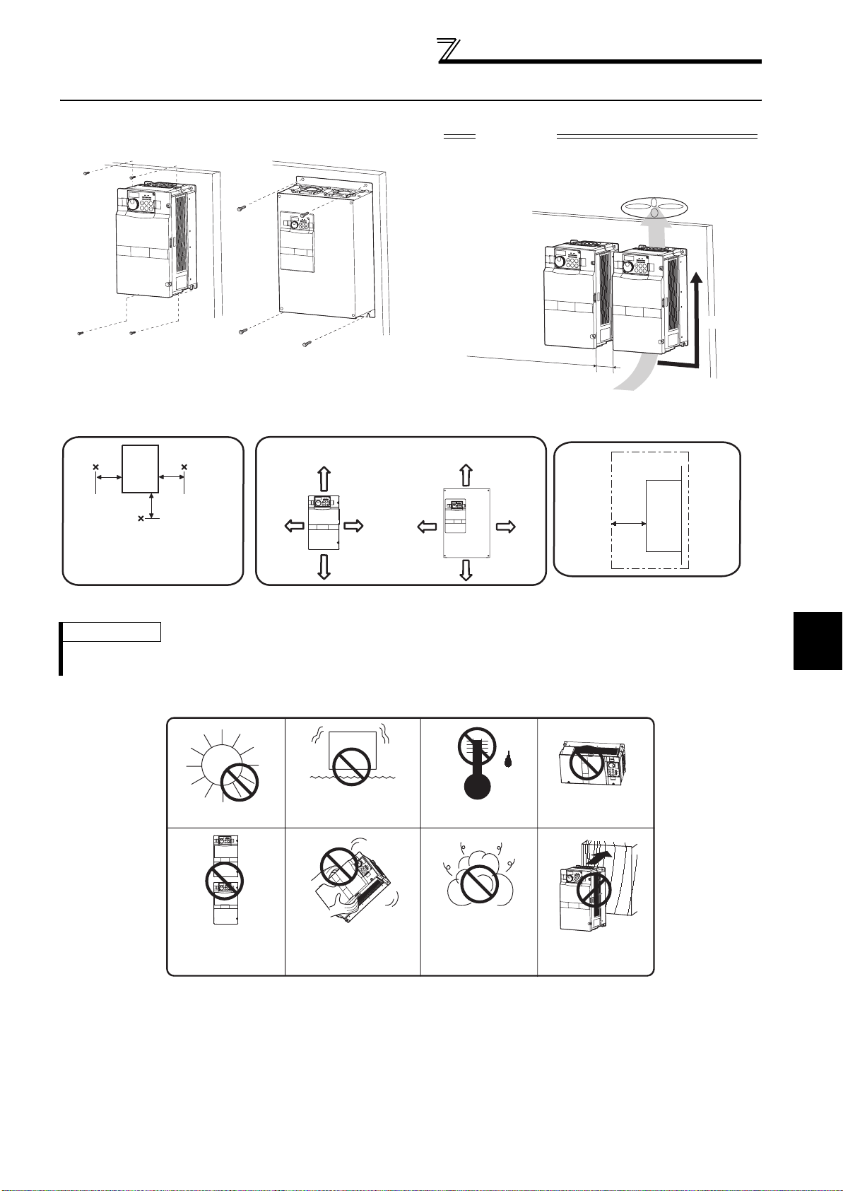
2.3 Installation of the inverter and instructions
• Installation of the Inverter
Installation on the enclosure
30K or less 37K or more
CAUTION
⋅ When encasing multiple inverters, install them in
parallel as a cooling measure.
⋅ Install the inverter vertically.
Vertical
Fix six positions for the FR-F740185K to 400K and fix eight positions
for the FR-F740-450K to 560K.
Refer to the clearances below.
• Install the inverter under the following conditions.
10cm
or more
(front)
20cm or more
10cm
or more
20cm or more
Clearances (side)
Inverter
5cm
or more
*
*1cm or more for 3.7K or less
Surrounding air temperature and humidity
Measurement
position
Inverter
5cm
Measurement
position
5cm
5cm
Temperature: -10°C to 50°C
Humidity: 90% RH maximum
Leave enough clearances as a
cooling measure.
Clearances
55K or less 75K or more
10cm or more
5cm
or more *
5cm
or more *
10cm or more
*1cm or more for 3.7K or less
REMARKS
•
For replacing the cooling fan of the FR-F740-185K or more, 30cm of space is necessary in front of the inverter.
Refer to page 130 for fan replacement.
• The inverter consists of precision mechanical and electronic parts. Never install or handle it in any of the following
conditions as doing so could cause an operation fault or failure.
2
Direct sunlight
Vertical mounting
(When installing two or
more inverters, install
them in parallel.)
Vibration(5.9m/s2 or more at 10 to
55Hz (directions of X, Y, Z axes))*
*2.9m/s2 or more for the 185K or
more
Transportation by
holding the front cover
High temperature,
high humidity
Oil mist, flammable
gas, corrosive gas,
fluff, dust, etc.
Horizontal placement
INSTALLATION AND WIRING
Mounting to
combustible material
7
Wiring
2.4 Wiring
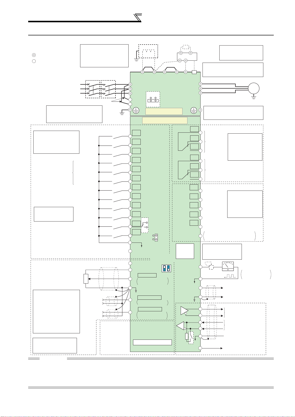
2.4.1 Terminal connection diagram
N/-
*8
resistor
Resistor unit
(Option)
Brake unit
(Option)
*7.
CN8
*6
U
V
W
C1
B1
A1
C2
B2
A2
RUN
Running
SU
Up to frequency
IPF
Instantaneous
power failure
OL
Overload
FU
Frequency detection
SE
*
9. It is not necessary
FM
SD
AM
5
TXD+
TXD-
RXD+
RXD-
SG
VCC
*6. A CN8 (for MT-BU5)
connector is provided
with the 75K or more.
Do not use PR and PX terminals.
Please do not remove the jumper
connected to terminal PR and PX.
Motor
*8.
The 200V class 0.75K and 1.5K
are not provided with the ON/OFF
connector EMC filter.
Relay output
Terminal functions
Relay output 1
(Fault output)
vary with the output
terminal assignment
(Pr. 195, Pr. 196)
(Refer to the chapter 4
of the Instruction
Manual (applied) )
Relay output 2
Open collector output
Terminal functions
vary with the output
terminal assignment
(Pr. 190 to Pr. 194)
(Refer to the chapter 4
of the Instruction
Manual (applied))
Open collector output common
/source common
Sink
when calibrating the
indicator from the
operation panel.
+-
Calibration
resistor *9
(+)
(-)
Indicator
(Frequency meter, etc.)
Moving-coil type
1mA full-scale
Analog signal output
(0 to 10VDC)
RS-485 terminals
Data transmission
Data reception
GND
(Permissible load
5V
current 100mA)
IM
Earth
(ground)
cable
Sink logic
Main circuit terminal
Control circuit terminal
Three-phase AC
power supply
*2. To supply power to the
control circuit separately,
remove the jumper across
R1/L11 and S1/L21.
*1. DC reactor (FR-HEL)
Be sure to connect the DC reactor
supplied with the 75K or more.
When a DC reactor is connected
to the 55K or less, remove the
jumper across P1-P/+.
Jumper
MC
*2
MCCB
Earth
(Ground)
*1
Earth
Jumper
(ground)
P1
P/+
R/L1
S/L2
T/L3
ON
R1/L11
S1/L21
OFF
Main circuit
Control circuit
Jumper
PR*7
EMC filter
ON/OFF
connector
PX*7
Control input signals (No voltage input allowed)
Terminal functions vary
with the input terminal
assignment
(Pr. 178 to Pr. 189)
(Refer to the chapter 4 of the
Instruction Manual (applied))
Start self-holding selection
Multi-speed
selection
Second function selection
*3. AU terminal can be
used as PTC input
terminal.
Terminal 4 input selection
(Current input selection)
Selection of automatic restart
after instantaneous
Contact input common
(Common for external power supply transistor)
Frequency setting signal (Analog)
Frequency setting
potentiometer
1/2W1k
*5
*
4. Terminal input specifications
can be changed by analog
input specifications switchover
(Pr. 73, Pr. 267). Set the
voltage/current input switch in
the OFF position to select
voltage input (0 to 5V/0 to
10V) and ON to select current
input (0 to 20mA).
(Refer to the chapter 4 of the
Instruction Manual (applied) )
Forward
rotation
start
Reverse
rotation
start
High speed
Middle speed
Low speed
Jog mode
Output stop
Reset
power failure
24VDC power supply
3
2
Ω
1
Auxiliary
input
Terminal
4 input
(Current
input)
(+)
(-)
(+)
(-)
Connector
for plug-in option
STF
STR
STOP
RH
RM
RL
JOG
RT
MRS
RES
*3
AU
AU
PTC
CS
SD
SOURCE
PC
*4
Voltage/current
10E(+10V)
10(+5V)
0 to 5VDC
2
0 to 10VDC
0 to 20mADC
5
(Analog common)
0 to ±10VDC
1
0 to ±5VDC
4 to 20mADC
4
0 to 5VDC
0 to 10VDC
SINK
input switch
2
4
ON
OFF
Initial value
selected
Initial
value
selected
Initial
value
*
selected
*
4
*
4
4
PU
connector
connection
*
5. It is recommended to use
2W1kΩ when the
frequency setting signal is
changed frequently.
Option connector 1
Terminating
CAUTION
· To prevent a malfunction due to noise, keep the signal cables more than 10cm away from the power cables. Also separate the
main circuit wire of the input side and the output side.
· After wiring, wire offcuts must not be left in the inverter.
Wire offcuts can cause an alarm, failure or malfunction. Always keep the inverter clean.
When drilling mounting holes in an enclosure etc., take care not to allow chips and other foreign matter to enter the inverter.
· Set the voltage/current input switch correctly. Operation with a wrong setting may cause a fault, failure or malfunction.
8

Wiring
r
r
2.4.2 EMC filter
This inverter is equipped with a built-in EMC filter (capacitive filter) and common mode choke.
The EMC filter is effective for reduction of air-propagated noise on the input side of the inverter.
The EMC filter is factory-set to disable (OFF). To enable it, fit the EMC filter ON/OFF connector to the ON position.
The input side common mode choke, built-in the 55K or less inverter, is always valid regardless of ON/OFF of the EMC
filter ON/OFF connector.
0.75K to 5.5K
EMC filter OFF EMC filter OFF EMC filter OFFEMC filter ON EMC filter ON EMC filter ON
(initial setting) (initial setting) (initial setting)
FR-F720-2.2K to 5.5K
FR-F740-0.75K to 5.5K
FR-F720-7.5K, 11K
FR-F740-7.5K, 11K
FR-F720-15K
FR-F740-15K, 18.5K
7.5K, 11K
FR-F720-18.5K to 30K
FR-F740-22K, 30K
15K or more
FR-F720- 37K or more
FR-F740- 37K or more
VUW
EMC filte
ON/OFF
connecto
The FR-F720-0.75K and 1.5K are not provided with the EMC filter ON/OFF connector. (Always ON)
<How to disconnect the connector>
(1) Before removing a front cover, check to make sure that the indication of the inverter operation panel is off, wait for
at least 10 minutes after the power supply has been switched off, and check that there are no residual voltage
using a tester or the like. (For the front cover removal method, refer to page 5.)
(2) When disconnecting the connector, push the fixing tab and pull the connector straight without pulling the cable or
forcibly pulling the connector with the tab fixed. When installing the connector, also engage the fixing tab securely.
If it is difficult to disconnect the connector, use a pair of long-nose pliers, etc.
2
EMC filter
ON/OFF connector
(Side view)
Disengage connector fixing tab With tab disengaged,
pull up connector straight.
CAUTION
⋅ Fit the connector to either ON or OFF.
⋅ Enabling (turning on) the EMC filter increase leakage current. (Refer to the chapter 3 of the Instruction Manual (applied))
WARNING
While power is on or when the inverter is running, do not open the front cover. Otherwise you may get an electric shock.
INSTALLATION AND WIRING
9
Wiring
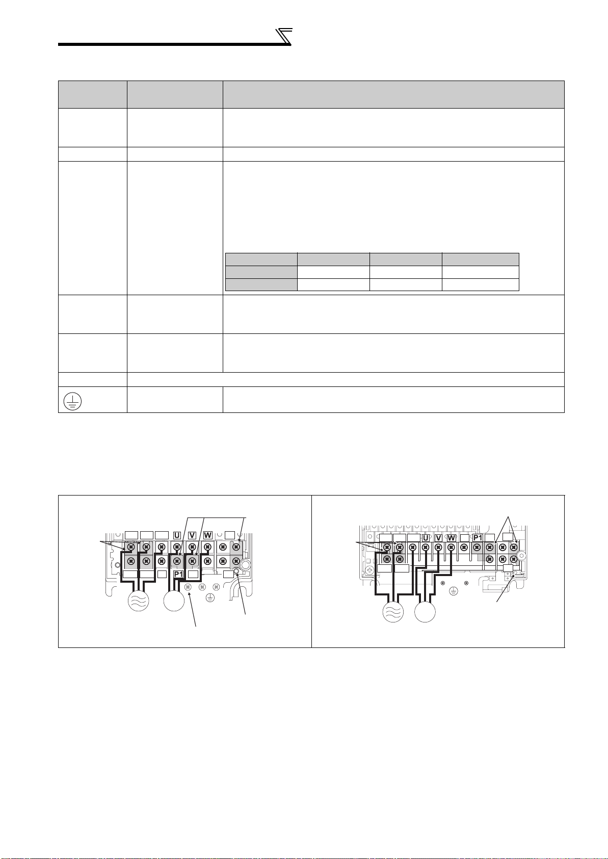
2.4.3 Specification of main circuit terminal
Termina l
Symbol
R/L1,
S/L2,
T/L3
Terminal Name Description
Connect to the commercial power supply.
AC power input
Keep these terminals open when using the high power factor converter
(FR-HC, MT-HC) or power regeneration common converter (FR-CV).
U, V, W Inverter output Connect a three-phase squirrel-cage motor.
Connected to the AC power supply terminals R/L1 and S/L2. To retain the
fault display and fault output or when using the high power factor converter
(FR-HC, MT-HC) or power regeneration common converter (FR-CV),
remove the jumpers from terminals R/L1-R1/L11 and S/L2-S1/L21 and
R1/L11,
S1/L21
P/+, N/-
P/+, P1
Power supply for
control circuit
Brake unit
connection
DC reactor
connection
apply external power to these terminals.
The power capacity necessary when separate power is supplied from R1/
L11 and S1/L21 differs according to the inverter capacity.
15K or less 18.5K 22K or more
200V class 60VA 80VA 80VA
400V class 60VA 60VA 80VA
Connect the brake unit (FR-BU2, FR-BU, BU and MT-BU5), power
regeneration common converter (FR-CV), high power factor converter (FRHC and MT-HC) or power regeneration converter (MT-RC).
For the 55K or less, remove the jumper across terminals P/+ - P1 and
connect the DC reactor. (Be sure to connect the DC reactor supplied with
the 75K or more.)
PR, PX Please do not remove or use terminals PR and PX or the jumper connected.
Earth (ground) For earthing (grounding) the inverter chassis. Must be earthed (grounded).
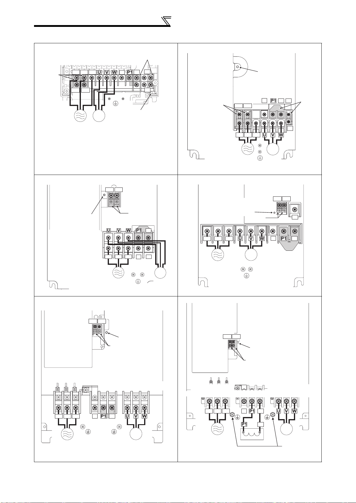
2.4.4 Terminal arrangement of the main circuit terminal, power supply and the motor wiring
200V class
FR-F720-0.75K, 1.5K FR-F720-2.2K to 5.5K
Jumper
Screw size (M4)
R/L1
S/L2
R1/L11
S1/L21
Power supply
Jumper
T/L3
N/-
P/+
IM
Motor
As this is an inside cover fixing screw,
do not remove it.
PX
Screw size
(M4)
PR
Charge lamp
Jumper
Screw size (M4)
R/L1 S/L2 T/L3
R1/L11 S1/L21
Power
supply
IM
Motor
N/-
Screw size
(M4)
Jumper
PR
P/+
PX
Charge lamp
10
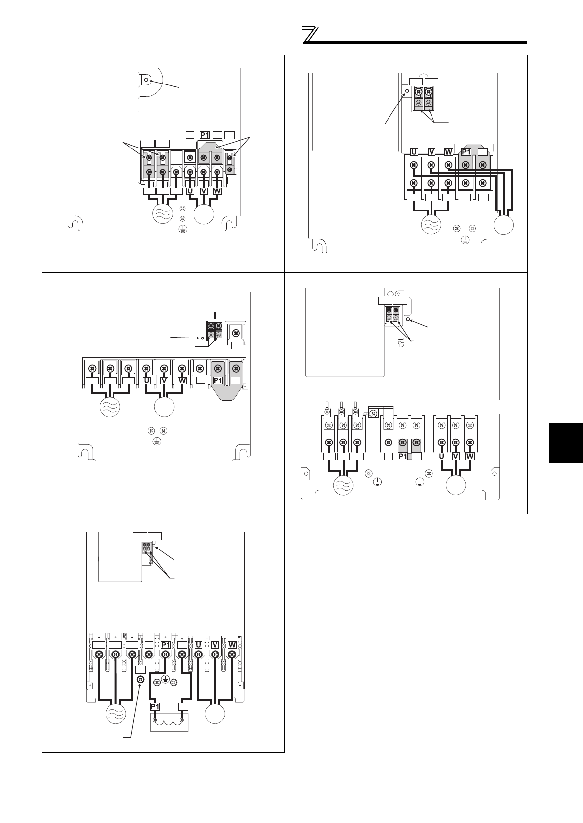
FR-F720-7.5K, 11K FR-F720-15K
r
Wiring
Charge lamp
Jumper
Screw size
(M5)
**
R1/L11 S1/L21
R/L1 S/L2 T/L3
N/-
P/+
PR
*
PX
Jumpe
*
Charge lamp
Screw size (M5)
IM
Power supply
* Screw size of terminal
R1/L11, S1/L21, PR
and PX is M4.
Screw size (M5)
FR-F720-18.5K to 30K FR-F720-37K to 55K
Screw size (M4)
Screw size
(18.5K:M6, 22K/30K:M8)
Charge lamp
Jumper
Motor
R1/L11 S1/L21
Screw size
(M4)
PR
R1/L11 S1/L21
R/L1 S/L2 T/L3
Power supply
R1/L11 S1/L21
Screw size
Charge lamp
Jumper
(M4)
Jumper
Jumper
P/+
N/-
PR
Screw size (M5)
IM
Motor
R/L1 S/L2 T/L3
Power supply
FR-F720-75K to 110K
R/L1 S/L2 T/L3
IM
Motor
Screw size (M6)
R1/L11 S1/L21
Screw size (M4)
N/-
N/-
Jumper
Charge lamp
Jumper
Screw size (M12)
P/+
P/+
R/L1 S/L2 T/L3
Power
supply
Screw size(37K:M8, 45K/55K:M10)
N/-
P/+
Jumper
Screw size
(37K:M6, 45K/55K:M8)
2
IM
Motor
INSTALLATION AND WIRING
Power supply
Screw size (M12)
(for option)
P/+
Screw size
(M10)
P/+
DC reactor
IM
Motor
11
Wiring
r
400V class
FR-F740-0.75K to 5.5K FR-F740-7.5K, 11K
Jumper
PR
P/+
PX
Charge lamp
Jumper
Screw size
Jumper
Screw size (M4)
R/L1 S/L2 T/L3
R1/L11 S1/L21
Power
supply
IM
Motor
N/-
Screw size
(M4)
FR-F740-15K, 18.5K FR-F740-22K, 30K
R1/L11 S1/L21
Screw size
(M4)
Charge lamp
Screw size (M5)
Jumper
Jumper
Screw size (M6)
P/+
R/L1 S/L2 T/L3
R1/L11 S1/L21
(M4)
R/L1 S/L2 T/L3
Power supply
Charge lamp
Charge lamp
N/-
IM
Motor
Screw size
(M4)
Screw size (M4)
Jumper
P/+
PR
R1/L11 S1/L21
N/-
Jumpe
PX
PR
P/+
R/L1 S/L2 T/L3
N/-
PR
Power supply
IM
Power supply
Screw size (M5)
FR-F740-37K to 55K FR-F740-75K to 110K
R1/L11 S1/L21
Screw size(M4)
Charge lamp
Jumper
Screw size (37K: M6, 45K/55K: M8)
N/-
R/L1 S/L2 T/L3
Power
supply
Screw size
(37K: M6, 45K/55K: M8)
P/+
Jumper
IM
Motor
Motor
R1/L11 S1/L21
Screw size (M4)
Screw size
(75K: M8, 90K/110K: M10)
R/L1 S/L2 T/L3
Power
supply
IM
Motor
Screw size (M6)
Charge lamp
Jumper
Screw size (M10)
N/-
P/+
P/+
DC reactor
Jumper
Screw size
(75K: M8, 90K/110K: M10)
IM
Motor
Screw size
(75K: M8,
90K/110K: M10)
12
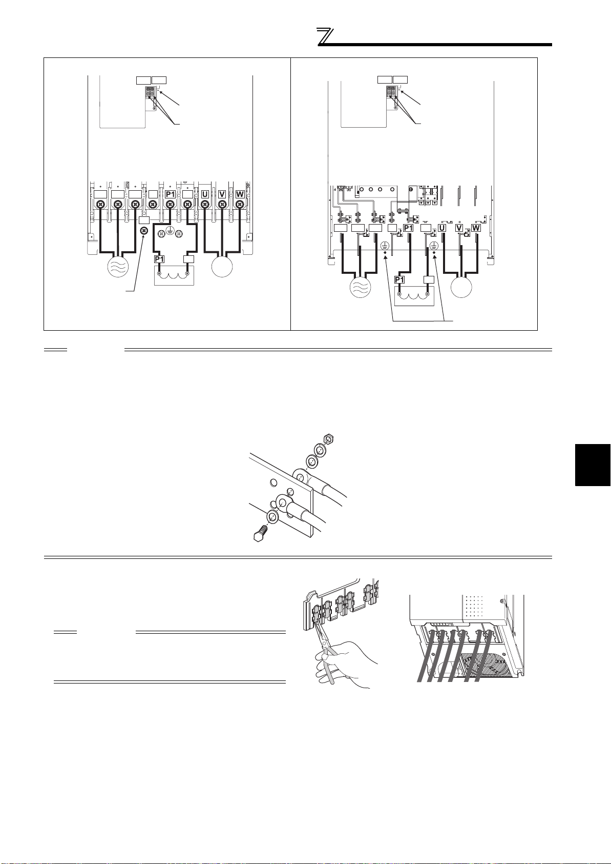
FR-F740-132K to 220K FR-F740-250K to 560K
R1/L11 S1/L21
Screw size (M4)
R1/L11 S1/L21
Wiring
Screw size (M4)
Charge lamp
Jumper
Screw size (M12)
P/+
R/L1 S/L2 T/L3
P/+
N/-
Screw size
(M10)
Charge lamp
Jumper
Screw size
(132K/160K: M10
185K/220K: M12)
P/+
P/+
R/L1 S/L2 T/L3
N/-
IM
Power supply
Screw size (M12)
(for option)
DC reactor
Motor
Power supply
CAUTION
· The power supply cables must be connected to R/L1, S/L2, T/L3. (Phase sequence needs not to be matched.) Never connect
the power cable to the U, V, W of the inverter. Doing so will damage the inverter.
· Connect the motor to U, V, W. At this time, turning on the forward rotation switch (signal) rotates the motor in the
counterclockwise direction when viewed from the motor shaft.
· When wiring the inverter main circuit conductor of the 250K or more, tighten a nut from the right side of the conductor. When
wiring two wires, place wires on both sides of the conductor. (Refer to the drawing below.) For wiring, use bolts (nuts) provided
with the inverter.
P/+
IM
Motor
DC reactor
Screw size (M10)
• Handling of the wiring cover
(FR-F720-18.5K, 22K, FR-F740-22K, 30K)
For the hook of the wiring cover, cut off the necessary
parts using a pair of long-nose pliers etc.
CAUTION
Cut off the same number of lugs as wires. If parts where
no wire is put through has been cut off (10mm or more),
protective structure (JEM1030) becomes an open type
(IP00).
2
INSTALLATION AND WIRING
13

Wiring
(1) Cable sizes etc., of the main control circuit terminals and earth (ground) terminals
Select the recommended cable size to ensure that a voltage drop will be 2% max.
If the wiring distance is long between the inverter and motor, a main circuit cable voltage drop will cause the motor
torque to decrease especially at the output of a low frequency.
The following table indicates a selection example for the wiring length of 20m.
200V class (when input power supply is 220V)
Cable Sizes
AWG /MC M *2
R/L1,
S/L2,
T/L3
U, V, W
PVC, etc. (mm2) *3
R/L1,
S/L2,
T/L3
U, V, W
(Ground)
Earth
cable
Applicable Inverter
Type
FR-F720-0.75K to
2.2K
Crimping
Terminal
Screw
Size *4
Tightening
Tor que
N·m
Term inal
R/L1,
S/L2,
T/L3
U, V, W
HIV, etc. (mm2) *1
R/L1,
S/L2,
T/L3
U, V, W
Earth
(Ground)
cable
M4 1.5 2-4 2-4 2 2 2 14 14 2.5 2.5 2.5
FR-F720-3.7K M4 1.5 5.5-4 5.5-4 3.5 3.5 3.5 12 12 4 4 4
FR-F720-5.5K M4 1.5 5.5-4 5.5-4 5.5 5.5 5.5 10 10 6 6 6
FR-F720-7.5K M5 2.5 14-5 8-5 14 8 5.5 6 8 16 10 16
FR-F720-11K M5 2.5 14-5 14-5 14 14 14 6 6 16 16 16
FR-F720-15K M5 2.5 22-5 22-5 22 22 14 4 6 (
*5)2525 16
FR-F720-18.5K M6 4.4 38-6 38-6 38 38 22 2 2 35 35 25
FR-F720-22K M8 (M6) 7.8 38-8 38-8 38 38 22 2 2 35 35 25
FR-F720-30K M8 (M6) 7.8 60-8 60-8 60 60 22 1/0 1/0 50 50 25
FR-F720-37K M8 (M6) 7.8 80-8 80-8 80 80 22 3/0 3/0 70 70 35
FR-F720-45K
FR-F720-55K
FR-F720-75K
FR-F720-90K
FR-F720-110K
*1 The cable size is that of the cable (HIV cable (600V class 2 vinyl-insulated cable) etc.) with continuous maximum permissible temperature of
75°C. Assumes that the surrounding air temperature is 50°C or less and the wiring distance is 20m or less.
*2 The recommended cable size is that of the cable (THHW cable) with continuous maximum permissible temperature of 75°C. Assumes that the
surrounding air temperature is 40°C or less and the wiring distance is 20m or less.
(Selection example for use mainly in the United States.)
*3 For the 15K or less, the recommended cable size is that of the cable (PVC cable) with continuous maximum permissible temperature of 70°C.
Assumes that the surrounding air temperature is 40°C or less and the wiring distance is 20m or less.
For the 18.5K or more, the recommended cable size is that of the cable (XLPE cable) with continuous maximum permissible temperature of
90°C. Assumes that the surrounding air temperature is 40°C or less and wiring is performed in an enclosure.
(Selection example for use mainly in Europe.)
*4 The terminal screw size indicates the terminal size for R/L1, S/L2, T/L3, U, V, W, and a screw for earthing (grounding).
A screw for earthing (grounding) of the 22K or more is indicated in ( ).
*5 When connecting the option unit to P/+, P1, N/-, use THHN cables for the option and terminals R/L1, S/L2, T/L3, U, V, W.
M10 (M8)
M10 (M8)
M12 (M10)
M12 (M10)
M12 (M10)
14.7 100-10 100-10 100 100 38 4/0 4/0 95 95 50
14.7 100-10 100-10 100 100 38 4/0 4/0 95 95 50
24.5 150-12 150-12 125 125 38 MCM250 MCM250 ⎯⎯ ⎯
24.5 150-12 150-12 150 150 38 2×4/0 2×4/0 ⎯⎯⎯
24.5 100-12 100-12 2×100 2×100 38 2×4/0 2×4/0 ⎯⎯⎯
14
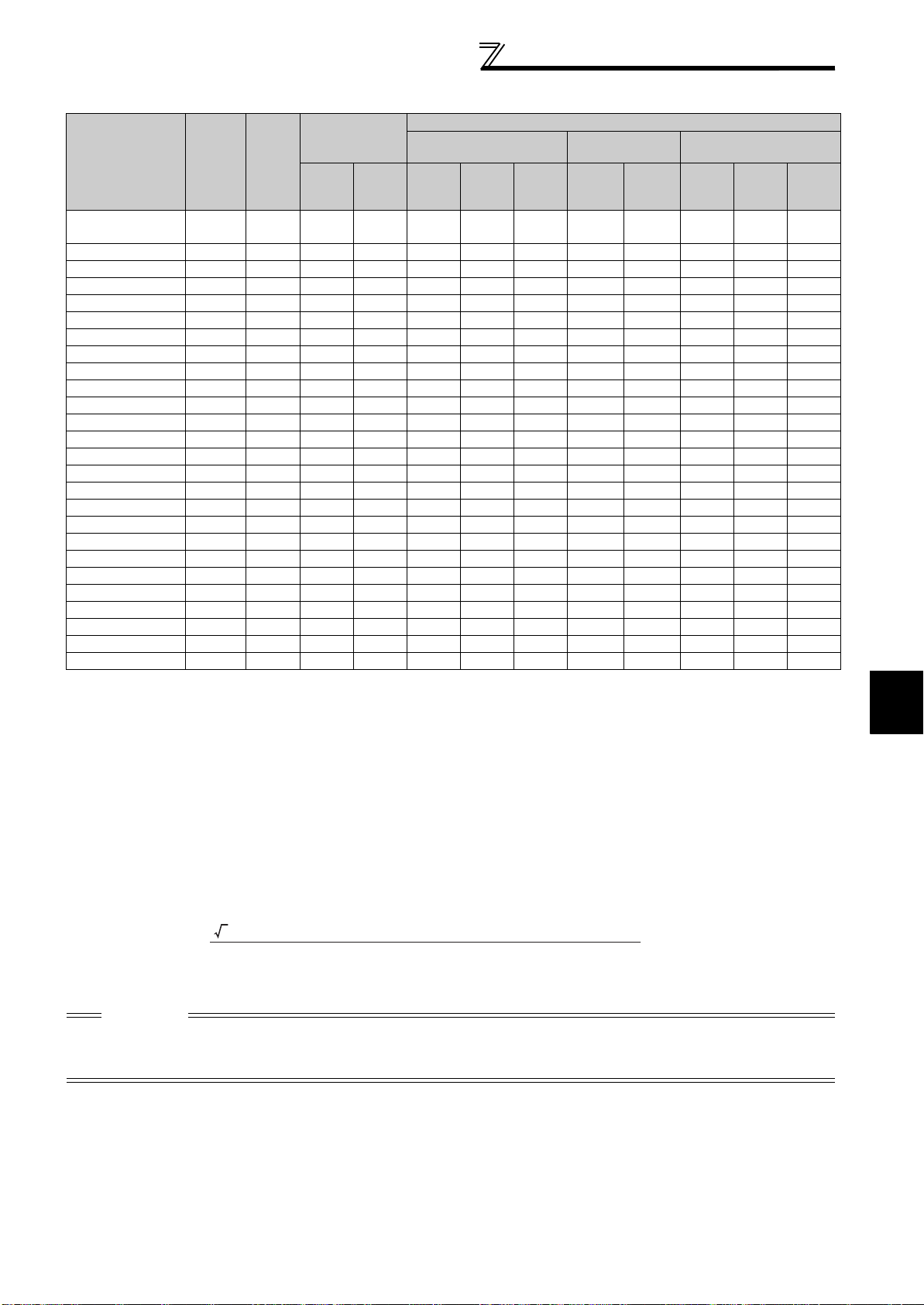
400V class (when input power supply is 440V)
Wiring
Applicable
Inverter Type
FR-F740-0.75K to
3.7K
Crimping
N·m
R/L1, S/L2,
(Compression)
Terminal
U, V, W
T/L3
HIV, etc. (mm2) *1
R/L1, S/L2,
T/L3
U, V, W
Earth
(Ground)
cable
Ter min al
Screw
Size *4
Tightening
Tor qu e
M4 1.5 2-4 2-4 2 2 2 14 14 2.5 2.5 2.5
Cable Sizes
AWG/MCM *2
R/L1, S/L2,
T/L3
U, V, W
PVC, etc. (mm2) *3
R/L1, S/L2,
T/L3
U, V, W
Earth
(Ground)
cable
FR-F740-5.5K M4 1.5 2-4 2-4 2 2 3.5 12 14 2.5 2.5 4
FR-F740-7.5K M4 1.5 5.5-4 5.5-4 3.5 3.5 3.5 12 12 4 4 4
FR-F740-11K M4 1.5 5.5-4 5.5-4 5.5 5.5 8 10 10 6 6 10
FR-F740-15K M5 2.5 8-5 8-5 8 8 8 8 8 10 10 10
FR-F740-18.5K M5 2.5 14-5 8-5 14 8 14 6 8 16 10 16
FR-F740-22K M6 4.4 14-6 14-6 14 14 14 6 6 16 16 16
FR-F740-30K M6 4.4 22-6 22-6 22 22 14 4 4 25 25 16
FR-F740-37K M6 4.4 22-6 22-6 22 22 14 4 4 25 25 16
FR-F740-45K M8 7.8 38-8 38-8 38 38 22 1 2 50 50 25
FR-F740-55K M8 7.8 60-8 60-8 60 60 22 1/0 1/0 50 50 25
FR-F740-75K M8 7.8 60-8 60-8 60 60 38 1/0 1/0 50 50 25
FR-F740-90K M10 14.7 60-10 60-10 60 60 38 3/0 3/0 50 50 25
FR-F740-110K M10 14.7 80-10 80-10 80 80 38 3/0 3/0 70 70 35
FR-F740-132K M10 14.7 100-10 100-10 100 100 38 4/0 4/0 95 95 50
FR-F740-160K M10 14.7 150-10 150-10 125 125 38 250 250 120 120 70
FR-F740-185K
FR-F740-220K
FR-F740-250K
FR-F740-280K
FR-F740-315K
FR-F740-355K
FR-F740-400K
FR-F740-450K
FR-F740-500K
FR-F740-560K
*1 For the FR-F740-55K or less, the recommended cable size is that of the cable (e.g. HIV cable (600V class 2 vinyl-insulated cable)) with continuous
maximum permissible temperature of 75°C. Assumes that the surrounding air temperature is 50°C or less and the wiring distance is 20m or less.
For the FR-F740-75K or more, the recommended cable size is that of the cable (e.g. LMFC (heat resistant flexible cross-linked polyethylene insulated
cable)) with continuous maximum permissible temperature of 90°C. Assumes that the surrounding air temperature is 50°C or less and wiring is performed
in an enclosure.
*2 For the FR-F740-45K or less, the recommended cable size is that of the cable (THHW cable) with continuous maximum permissible temperature of 75°C.
Assumes that the surrounding air temperature is 40°C or less and the wiring distance is 20m or less.
For the FR-F740-55K or more, the recommended cable size is that of the cable (THHN cable) with continuous maximum permissible temperature of 90°C.
Assumes that the surrounding air temperature is 40°C or less and wiring is performed in an enclosure.
(Selection example for use mainly in the United States.)
*3 For the FR-F740-45K or less, the recommended cable size is that of the cable (PVC cable) with continuous maximum permissible temperature of 70°C.
Assumes that the surrounding air temperature is 40°C or less and the wiring distance is 20m or less.
For the FR-F740-55K or more, the recommended cable size is that of the cable (XLPE cable) with continuous maximum permissible temperature of 90°C.
Assumes that the surrounding air temperature is 40°C or less and wiring is performed in an enclosure.
(Selection example for use mainly in the Europe.)
*4 The terminal screw size indicates the terminal size for R/L1, S/L2, T/L3, U, V, W
A screw for earthing (grounding) of the 185K or more is indicated in ( ).
M12 (M10)
M12 (M10)
M12 (M10)
M12 (M10)
M12 (M10)
M12 (M10)
M12 (M10)
M12 (M10)
M12 (M10)
M12 (M10)
24.5 150-12 150-12 150 150 38 300 300 150 150 95
24.5 100-12 100-12 2×100 2×100 38 2×4/0 2×4/0 2×95 2×95 95
24.5 100-12 100-12 2×100 2×100 38 2×4/0 2×4/0 2×95 2×95 95
24.5 150-12 150-12 2×125 2×125 38 2×250 2×250 2×120 2×120 120
24.5 150-12 150-12 2×150 2×150 38 2×300 2×300 2×150 2×150 150
24.5 200-12 200-12 2×200 2×200 60 2×350 2×350 2×185 2×185 2×95
24.5 C2-200 C2-200 2×200 2×200 60 2×400 2×400 2×185 2×185 2×95
24.5 C2-250 C2-250 2×250 2×250 60 2×500 2×500 2×240 2×240 2×120
24.5 C2-250 C2-250 2×250 2×250 100 2×500 2×500 2×240 2×240 2×120
24.5 C2-200 C2-200 3×200 3×200 100 3×350 3×350 3×185 3×185 2×150
,
and a screw for earthing (grounding).
The line voltage drop can be calculated by the following formula:
2
line voltage drop [V]=
3 × wire resistance[mΩ/m] × wiring distance[m] × current[A]
1000
Use a larger diameter cable when the wiring distance is long or when it is desired to decrease the voltage drop (torque
reduction) in the low speed range.
CAUTION
· Tighten the terminal screw to the specified torque.
A screw that has been tighten too loosely can cause a short circuit or malfunction.
A screw that has been tighten too tightly can cause a short circuit or malfunction due to the unit breakage.
· Use crimping terminals with insulation sleeve to wire the power supply and motor.
15
INSTALLATION AND WIRING
Wiring
(2) Notes on earthing (grounding)
• Leakage currents flow in the inverter. To prevent an electric shock, the inverter and motor must be earthed (grounded). This
inverter must be earthed (grounded). Earthing (Grounding) must conform to the requirements of national and local safety
regulations and electrical codes. (NEC section 250, IEC 536 class 1 and other applicable standards)
A neutral-point earthed (grounded) power supply for 400V class inverter in compliance with EN standard must be used.
• Use the dedicated earth (ground) terminal to earth (ground) the inverter.
(Do not use the screw in the casing, chassis, etc.)
• Use the thickest possible
14
, 15 and minimize the cable length. The earthing (grounding) point should be as near as possible to the inverter.
To be compliant with the EU Directive (Low Voltage Directive), earth (ground) the inverter according to
the instructions on page 155.
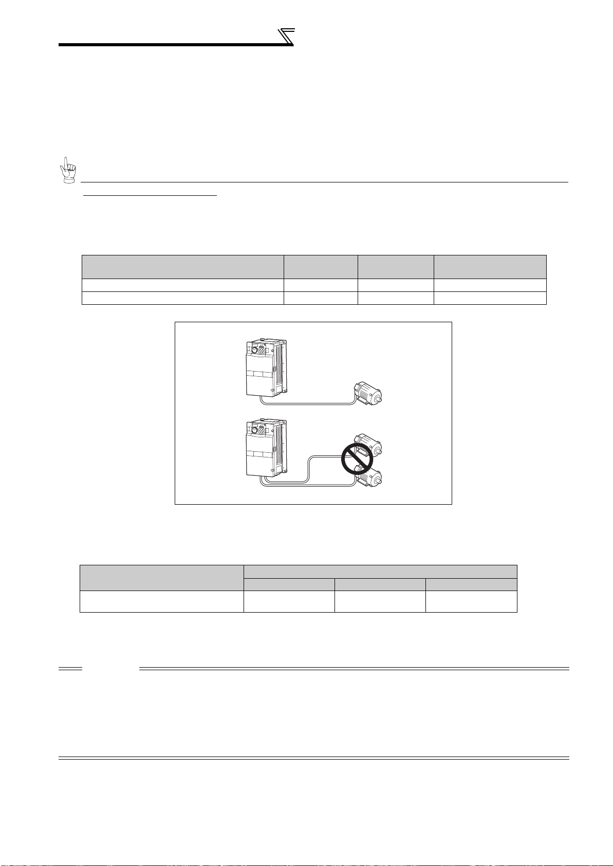
(3) Total wiring length
The overall wiring length for connection of a single motor or multiple motors should be within the value in the table below.
earth (ground)
cable. Use the cable whose size is equal to or greater than that indicated in
page
Pr. 72 PWM frequency selection Setting
(carrier frequency)
2 (2kHz) or less 300m 500m 500m
3 to 15 (3kHz to 14.5kHz) * 200m 300m 500m
0.75K 1.5K 2.2K or More
* For the 75K or more, the setting range of Pr. 72 PWM frequency selection is "0 to 6".
Total wiring length (1.5K or more)
500m or less
300m
300m
300m + 300m = 600m
When driving a 400V class motor by the inverter, surge voltages attributable to the wiring constants may occur at the
motor terminals, deteriorating the insulation of the motor.
Take the following measures 1) or 2) in this case.
1) Use a "400V class inverter-driven insulation-enhanced motor" and set frequency in Pr. 72 PWM frequency selection
according to wiring length
Wiring Length
50m or less 50m to 100m exceeding 100m
Pr. 72 PWM frequency selection Setting
(carrier frequency)
14.5kHz or less 9kHz or less 4kHz or less
2) Connect the surge voltage suppression filter (FR-ASF-H) to the 55K or less and the sine wave filter (MT-BSL/BSC)
to the 75K or more on the inverter output side.
CAUTION
· Especially for long-distance wiring, the inverter may be affected by a charging current caused by the stray capacitances of the
wiring, leading to a malfunction of the overcurrent protective function or fast response current limit function or a malfunction or fault
of the equipment connected on the inverter output side. If fast-response current limit function malfunctions, disable this function.
(For Pr.156 Stall prevention operation selection, refer to the chapter 4 of the Instruction Manual (applied).)
· For details of Pr. 72 PWM frequency selection , refer to the chapter 4 of the Instruction Manual (applied). (When using an optional sine
wave filter (MT-BSL/BSC) for the 75K or more, set "25" in Pr.72 (2.5kHz)).
· For explanation of surge voltage suppression filter (FR-ASF-H) and sine wave filter (MT-BSL/BSC), refer to the manual of each
option.
16
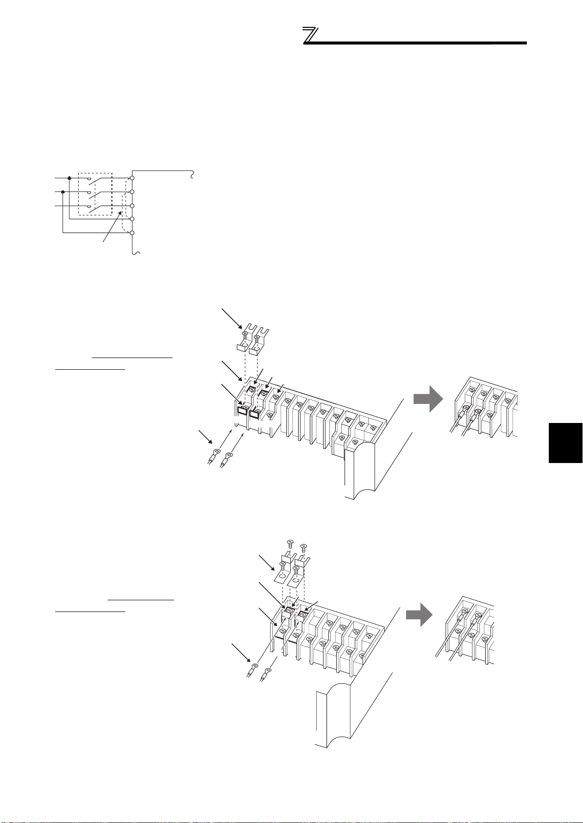
Wiring
(4) Cable size of the control circuit power supply (terminal R1/L11, S1/L21)
· Terminal Screw Size: M4
· Cable size: 0.75mm
· Tightening torque: 1.5N·m
(5) When connecting the control circuit and the main circuit separately to the power supply
<Connection diagram> When fault occurs, opening of the electromagnetic contactor (MC) on the
MC
Remove the jumper
• FR-F720-0.75K to 5.5K, FR-F740-0.75K to 5.5K
2
to 2mm
R/L1
S/L2
T/L3
R1/L11
S1/L21
2
Inverter
inverter power supply side results in power loss in the control circuit,
disabling the fault output signal retention. Terminals R1/L11 and S1/L21 are
provided for when retention of a fault signal is required. In this case, connect
the power supply terminals R1/L11 and S1/L21 of the control circuit to the
primary side of the MC.
Do not connect the power cable to incorrect terminals. Doing so may
damage the inverter.
1)Loosen the upper screws.
2)Remove the lower screws.
3)
3)Remove the jumper
4)Connect the separate power
supply cable for the control
circuit to the lower terminals
1)
(R1/L11, S1/L21).
2)
4)
R1/L11
• FR-F720-7.5K, 11K, FR-F740-7.5K, 11K
1)Remove the upper screws.
2)Remove the lower screws.
3)Remove the jumper.
4)Connect the separate power
supply cable for the control
circuit to the upper terminals
(R1/L11, S1/L21).
R/L1
S/L2
T/L3
S1/L21
Main circuit terminal block
3)
1)
R1/L11
2)
S1/L21
R1/L11
S1/L21
R1/L11
2
S1/L21
INSTALLATION AND WIRING
4)
R/
S/
L1
T/
L2
L3
Main circuit
terminal block
17
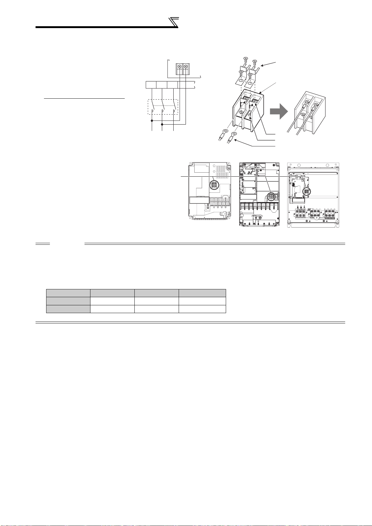
Wiring
• FR-F720-15K, FR-F740-15K or more
1)Remove the upper screws.
2)Remove the lower screws.
3)Pull the jumper toward you to
remove.
4)
Connect the separate power supply
cable for the control circuit to the
upper terminals (R1/L11, S1/L21)
.
R/L1
MC
S/L2
T/L3
R1/
L11
S1/
L21
Power supply
terminal block
for the control circuit
3)
Power supply terminal block
for the control circuit
R1/L11
S1/L21
Main power supply
Power supply
terminal block for
the control circuit
FR-F720-15K
FR-F740-15K, 18.5K
FR-F720-18.5K to 30K
FR-F740-22K, 30K
1)
2)
4)
FR-F720-37K or more
FR-F740-37K or more
VUW
CAUTION
· Be sure to use the inverter with the jumpers across terminals R/L1-R1/L11 and S/L2-S1/L21 removed when supplying power
from other sources. The inverter may be damaged if you do not remove the jumper.
· The voltage should be the same as that of the main control circuit when the control circuit power is supplied from other than the
primary side of the MC.
· The power capacity necessary when separate power is supplied from R1/L11 and S1/L21 differs according to the inverter
capacity.
15K or less 18.5K 22K or more
200V class 60VA 80VA 80VA
400V class 60VA 60VA 80VA
· If the main circuit power is switched off (for 0.1s or more) then on again, the inverter resets and a fault output will not be held.
18
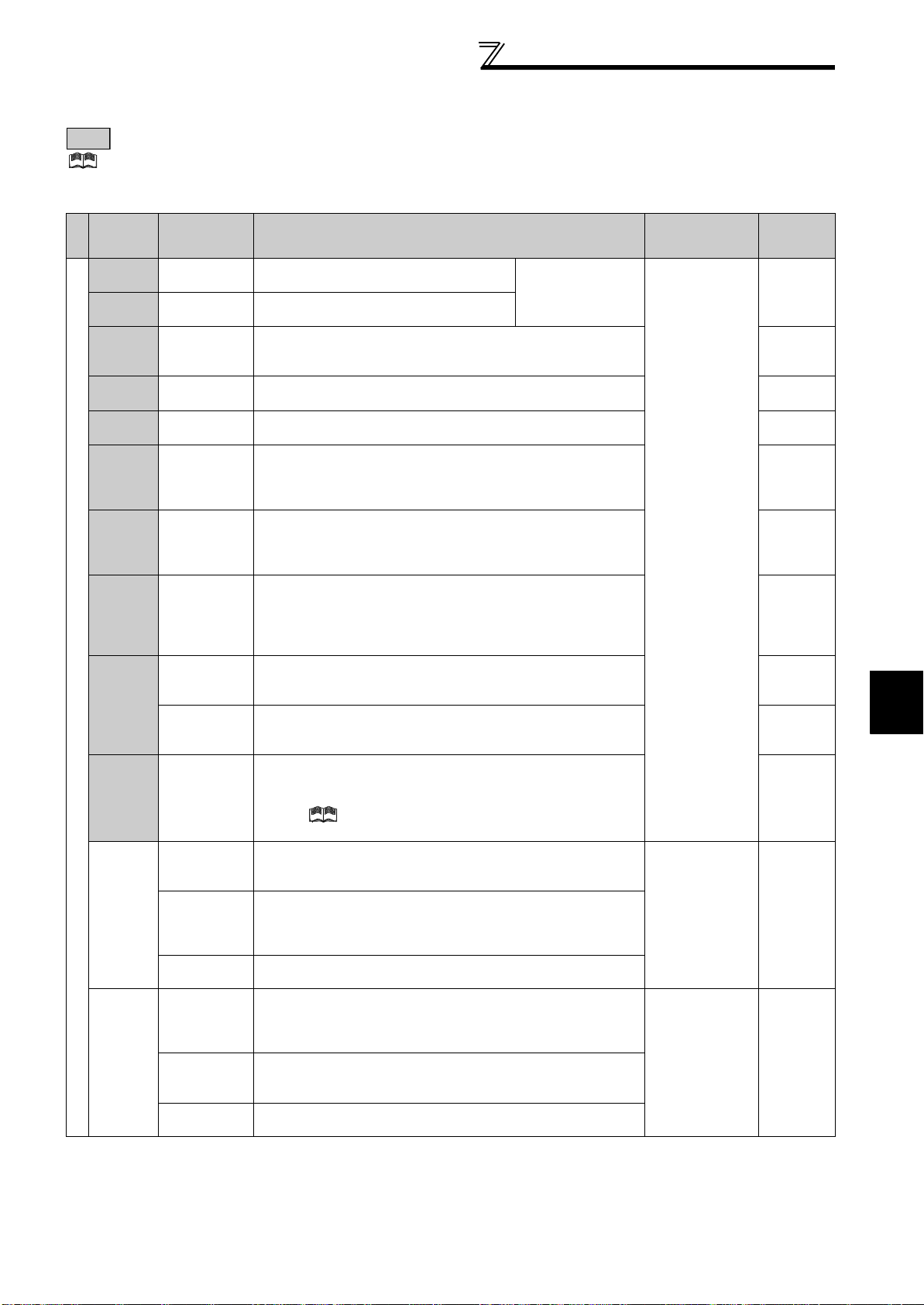
2.4.5 Control circuit terminals
indicates that terminal functions can be selected using Pr. 178 to Pr. 196 (I/O terminal function selection) (Refer to the chapter 4 of
the Instruction Manual (applied).)
(1) Input signals
Wiring
Terminal
Symbol
Type
STF
STR
STOP
RH,
RM, RL
JOG
RT
MRS Output stop
RES Reset
AU
Contact input
CS
SD
PC
Terminal
Name
Forward
rotation start
Reverse
rotation start
Star t selfholding
selection
Multi-speed
selection
Jog mode
selection
Second
function
selection
Terminal 4
input selection
PTC input
Selection of
automatic
restart after
instantaneous
power failure
Contact input
common (sink)
(initial setting)
External
transistor
common
(source)
24VDC power
supply common
External
transistor
common (sink)
(initial setting)
Contact input
common
(source)
24VDC power
supply
Description
Turn on the STF signal to start forward
rotation and turn it off to stop.
Turn on the STR signal to start reverse
rotation and turn it off to stop.
Turn on the STOP signal to self-hold the start signal. *2
Multi-speed can be selected according to the combination of RH,
RM and RL signals.
Turn on the JOG signal to select Jog operation (initial setting) and
turn on the start signal (STF or STR) to start Jog operation.
Turn on the RT signal to select second function.
When the second function such as "second torque boost" and
"second V/F (base frequency)" are set, turning on the RT signal
selects these functions.
Turn on the MRS signal (20ms or more) to stop the inverter
output.
Use to shut off the inverter output when stopping the motor by
electromagnetic brake.
Used to reset fault output provided when fault occurs.
Turn on the RES signal for more than 0.1s, then turn it off.
Initial setting is for reset always. By setting Pr.75, reset can be set
to enabled only at fault occurrence. Inverter recovers about 1s
after the reset is released.
Terminal 4 is valid only when the AU signal is turned on. (The
frequency setting signal can be set between 0 and 20mADC.)
Turning the AU signal on makes terminal 2 (voltage input) invalid.
AU terminal is used as PTC input terminal (thermal protection of
the motor). When using it as PTC input terminal, set the AU/PTC
switch to PTC.
When the CS signal is left on, the inverter restarts automatically at
power restoration. Note that restart setting is necessary for this
operation. In the initial setting, a restart is disabled.
(Refer to Pr. 57 Restart coasting time in the chapter 4 of the
Instruction Manual (applied).)
Common terminal for contact input terminal (sink logic) and terminal
FM.
When connecting the transistor output (open collector output), such
as a programmable controller, when source logic is selected, connect
the external power supply common for transistor output to this
terminal to prevent a malfunction caused by undesirable currents.
Common output terminal for 24VDC 0.1A power supply (PC terminal).
Isolated from terminals 5 and SE.
When connecting the transistor output (open collector output), such
as a programmable controller, when sink logic is selected, connect
the external power supply common for transistor output to this
terminal to prevent a malfunction caused by undesirable currents.
Common terminal for contact input terminal (source logic).
Can be used as 24VDC 0.1A power supply.
When the STF and
STR signals are turned
on simultaneously, the
stop command is given.
Rated
Specifications
Input resistance
4.7kΩ
Voltage at
opening: 21 to
27VDC
Contacts at
short-circuited: 4
to 6mADC
-------------- ------ —
Power supply
voltage range
19.2 to 28.8VDC
Permissible load
current 100mA
Refer to
57
59
*2
*2
*2
102
63
*2
*2
23
2
INSTALLATION AND WIRING
19

Wiring
Terminal
Symbol
Typ e
10E
10
Ter minal
Name
Frequency
setting power
supply
Description
When connecting the frequency setting potentiometer at an initial
status, connect it to terminal 10.
Change the input specifications of terminal 2 when connecting it
to terminal 10E. (Refer to Pr. 73 Analog input selection in the chapter
4 of the Instruction Manual (applied).)
Rated
Specifications
10VDC
Permissible load
current 10mA
5VDC
Permissible load
current 10mA
Voltage input:
Input resistance
Inputting 0 to 5VDC (or 0 to 10V, 0 to 20mA) provides the
2
setting
(voltage)
Frequency
maximum output frequency at 5V (10V, 20mA) and makes input
and output proportional. Use Pr. 73 to switch from among input 0
to 5VDC (initial setting), 0 to 10VDC, and 0 to 20mA.
Set the voltage/current input switch in the ON position to select
current input (0 to 20mA).
*1
10kΩ ± 1kΩ
Maximum
permissible
voltage 20VDC
Current input:
Input resistance
245Ω ± 5Ω
Maximum
permissible
current 30mA
Frequency setting
Inputting 4 to 20mADC (or 0 to 5V, 0 to 10V) provides the
maximum output frequency at 20mA (5V, 10V) makes input and
4
setting
(current)
Frequency
output proportional. This input signal is valid only when the AU
signal is on (terminal 2 input is invalid). Use Pr. 267 to switch from
among input 4 to 20mA (initial setting), 0 to 5VDC, and 0 to
10VDC. Set the voltage/current input switch in the OFF position
to select voltage input (0 to 5V/0 to 10V).
*1
(Refer to the chapter 4 of the Instruction Manual (applied).)
Voltage/current
input switch
Switch 1
Switch 2
2
4
Input resistance
1
setting
auxiliary
Frequency
Inputting 0 to ±5 VDC or 0 to ±10VDC adds this signal to terminal
2 or 4 frequency setting signal. Use Pr.73 to switch between the
input 0 to ±5VDC and 0 to ±10VDC (initial setting).
10kΩ ± 1kΩ
Maximum
permissible voltage
± 20VDC
5
setting
common
*1 Set Pr. 73, Pr. 267, and a voltage/current input switch correctly, then input an analog signal in accordance with the setting.
Applying a voltage signal with voltage/current input switch on (current input is selected) or a current signal with switch off (voltage input is
selected) could cause component damage of the inverter or analog circuit of signal output devices.
*2 Refer to the chapter 4 of
Frequency
Common terminal for frequency setting signal (terminal 2, 1 or 4)
and analog output terminal AM. Do not earth (ground).
the Instruction Manual (applied).
-------------- ------ ------
Refer to
*2
53, 61
53, 61
55, 63
*2
20
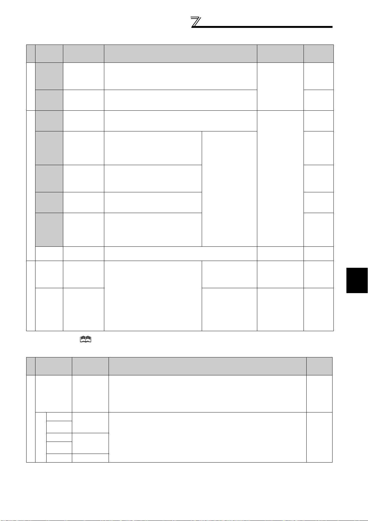
(2) Output signals
Wiring
Terminal
Symbol
Type
A1,
B1,
C1
Relay
A2,
B2,
C2
RUN
SU
OL
Open collector
IPF
FU
SE
FM For meter
Pulse
AM
Relay output 1
(Fault output)
Relay output 2 1 changeover contact output *
Inverter
running
Up to
frequency
Overload
warning
Instantaneous
power failure
Frequency
detection
Open collector
output common
Analog signal
output
Terminal
Name
Description
1 changeover contact output indicates that the inverter
protective function has activated and the output stopped.
Fault: No conduction across B-C (Across A-C Continuity),
Normal: Across B-C Continuity (No conduction across A-C)
Switched low when the inverter output frequency is equal to or
higher than the starting frequency (initial value 0.5Hz). Switched
high during stop or DC injection brake operation.
Switched low when the output
frequency reaches within the range of
±10% (initial value) of the set frequency.
Switched high during acceleration/
deceleration and at a stop.
Switched low when stall prevention is
activated by the stall prevention
function. Switched high when stall
prevention is cancelled.
Switched low when an instantaneous
power failure and under voltage
protections are activated.
Switched low when the inverter output
frequency is equal to or higher than the
preset detected frequency and high
when less than the preset detected
frequency.
C o m m o n t e r m i n a l f o r t e r m i n a l s R U N , S U , O L , I P F, F U -------------------- -----
Select one e.g. output frequency from
monitor items. (Not output during
inverter reset.)
The output signal is proportional to the
magnitude of the corresponding
monitoring item.
Alarm code (4bit)
output
Output item:
Output frequency
(initial setting)
Output item:
Output frequency
(initial setting)
Rated
Specifications
Contact capacity:
230VAC 0.3A
(Power
factor=0.4)
30VDC 0.3A
Permissible load
24VDC (27VDC
maximum) 0.1A
(A voltage drop is
3.4V maximum
when the signal is
on.)
Low is when the
open collector
output transistor
is on (conducts).
High is when the
transistor is off
(does not
conduct).
Permissible load
current 2mA
1440 pulses/s at
60Hz
Output signal 0 to
10VDC
Permissible load
current 1mA
(load impedance
10kΩ or more)
Resolution 8 bit
Refer to
*
*
*
*
*
*
*
2
*
* Refer to the chapter 4 of the Instruction Manual (applied).
(3) Communication
Typ e
RS-485
Terminal
Symbol
—
TXD+
TXD-
RXD+
RXD-
RS-485 terminals
SG
Terminal
Name
PU
connector
Inverter
transmission
terminal
Inverter
reception
terminal
Earth (Ground)
With the PU connector, communication can be made through RS-485.
(for connection on a 1:1 basis only)
Conforming standard : EIA-485 (RS-485)
Transmission format : Multidrop link
Communication speed : 4800 to 38400bps
Overall length : 500m
With the RS-485 terminals, communication can be made through RS-485.
Conforming standard : EIA-485 (RS-485)
Transmission format : Multidrop link
Communication speed : 300 to 38400bps
Overall length : 500m
Description Refer to
26
27
21
INSTALLATION AND WIRING
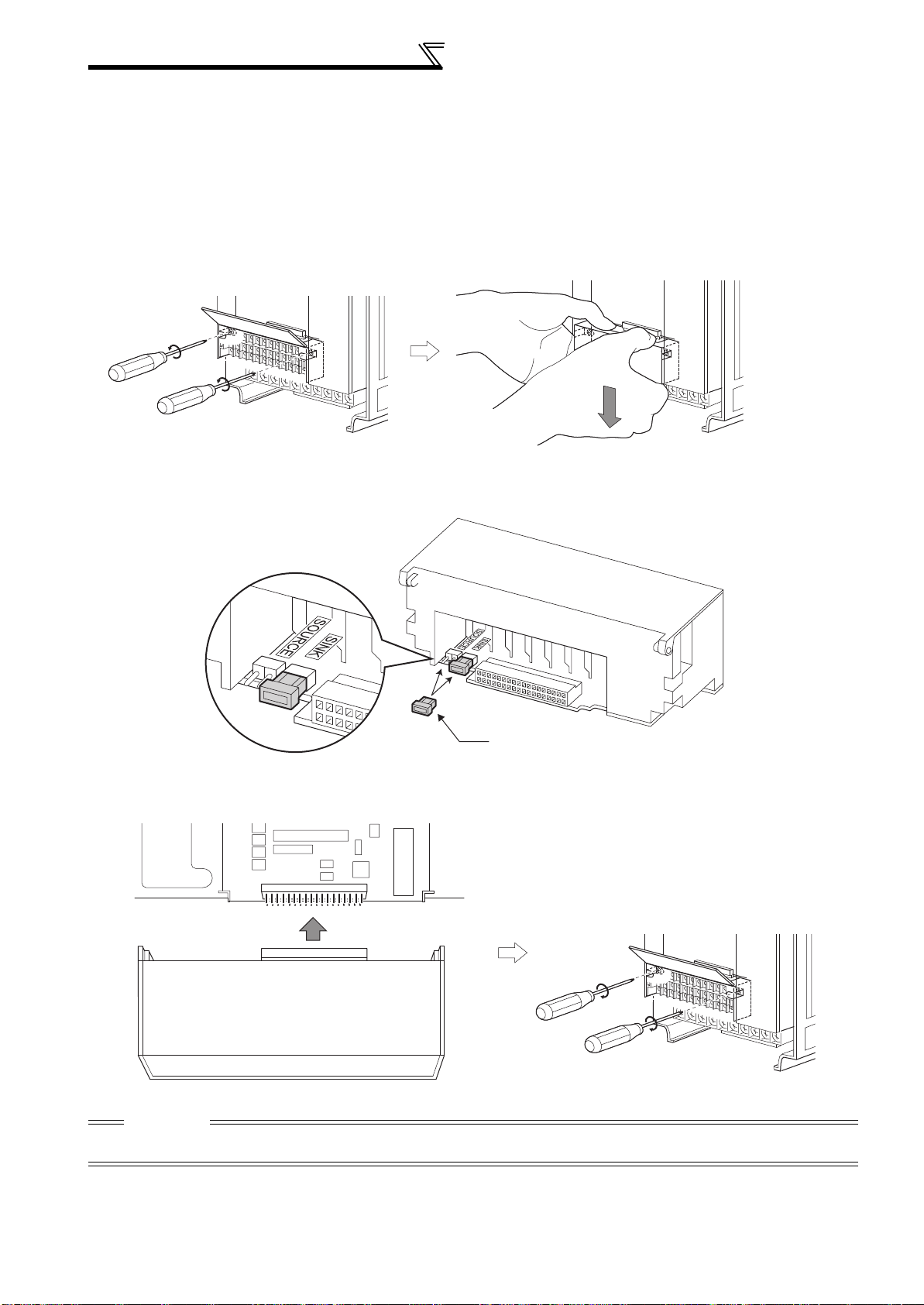
Wiring
2.4.6 Changing the control logic
The input signals are set to sink logic (SINK) when shipped from the factory.
To change the control logic, the jumper connector on the back of the control circuit terminal block must be moved to the
other position.
(The output signals may be used in either the sink or source logic independently of the jumper connector position.)
1)Loosen the two installation screws in both ends of the control circuit terminal block. (These screws cannot be
removed.)
Pull down the terminal block from behind the control circuit terminals.
2)Change the jumper connector set to the sink logic (SINK) on the rear panel of the control circuit terminal block to
source logic (SOURCE).
Jumper connector
3)Using care not to bend the pins of the inverter's control circuit connector, reinstall the control circuit terminal block
and fix it with the mounting screws.
CAUTION
1. Make sure that the control circuit connector is fitted correctly.
2. While power is on, never disconnect the control circuit terminal block.
22
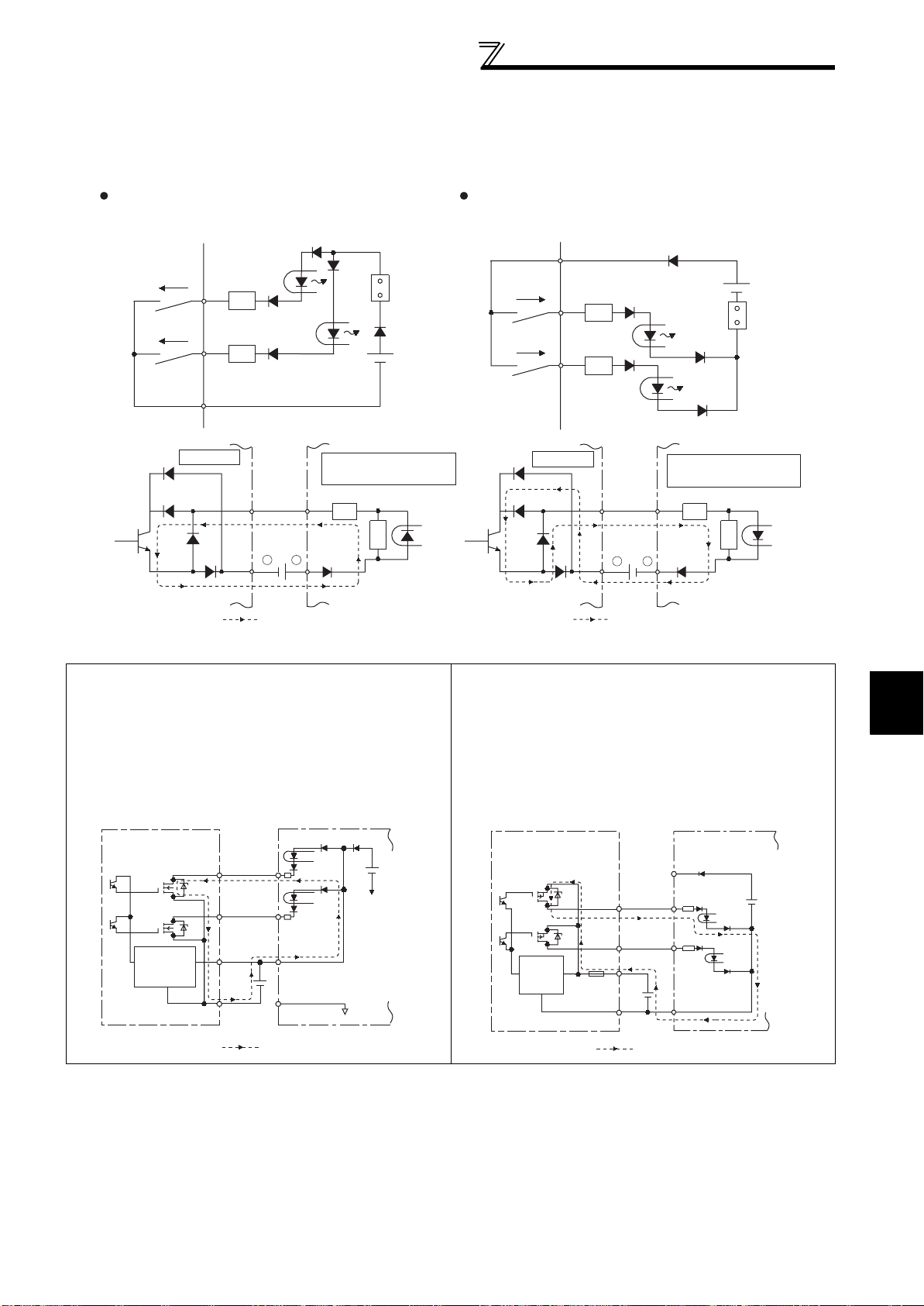
4) Sink logic and source logic
r
⋅ In sink logic, a signal switches on when a current flows from the corresponding signal input terminal.
Terminal SD is common to the contact input signals. Terminal SE is common to the open collector output signals.
⋅ In source logic, a signal switches on when a current flows into the corresponding signal input terminal.
Terminal PC is common to the contact input signals. Terminal SE is common to the open collector output signals.
Wiring
Current flow concerning the input/output signal
when sink logic is selected
Sink logic
Current
STF
STR
SD
Inverter
RUN
SE
R
R
TB1
-
+
TB17
24VDC
Current flow
DC input (sink type)
<Example: QX40>
R
R
Sink
connector
Current flow concerning the input/output signal
when source logic is selected
Source logic
PC
Current
STF
R
STR
R
Inverter
SE
RUN
+
24VDC
Current flow
DC input (source type)
<Example: QX80>
TB1
R
-
TB18
Source
connecto
R
• When using an external power supply for transistor output
⋅ Sink logic type
Use terminal PC as a common terminal, and perform
wiring as shown below. (Do not connect terminal SD of
the inverter with terminal 0V of the external power
supply. When using terminals PC-SD as a 24VDC
power supply, do not install a power supply in parallel in
the outside of the inverter. Doing so may cause a
malfunction due to undesirable current.)
QY40P type transistor
output unit
Constant
voltage
circuit
TB1
TB2
TB17
TB18
STF
STR
24VDC
Inverter
24VDC
(SD)
PC
SD
Current flow
⋅ Source logic type
Use terminal SD as a common terminal, and perform
wiring as shown below. (Do not connect terminal PC of
the inverter with terminal +24V of the external power
supply. When using terminals PC-SD as a 24VDC
power supply, do not install an external power supply in
parallel with the inverter. Doing so may cause a
malfunction in the inverter due to undesirable currents.)
QY80 type transistor
output unit
Constant
voltage
circuit
Fuse
TB1
TB2
TB17
TB18
Current flow
PC
STF
STR
24VDC
SD
Inverter
24VDC
(SD)
2
INSTALLATION AND WIRING
23
 Loading...