

Page 1

INVERTER
1
2
3
4
5
6
7
8
9
10
11
FR-F700PJ INSTRUCTION MANUAL (BASIC)
FR-F720PJ-0.4K to 15K (F)
FR-F740PJ-0.4K to 15K (F)
1
2
Thank you for choosing this Mitsubishi Electric Inverter.
This Instruction Manual (Basic) provides handling information and precautions for use of the equipment.
Please forward this Instruction Manual (Basic) to the end user.
CONTENTS
OUTLINE ...................................................................................1
INSTALLATION AND WIRING ...................................................6
PRECAUTIONS FOR USE OF THE INVERTER.........................20
FAILSAFE OF THE SYSTEM WHICH USES THE INVERTER ...22
DRIVING THE IPM MOTOR......................................................23
DRIVING THE MOTOR.............................................................25
ENERGY SAVING OPERATION FOR FANS AND PUMPS ........33
PARAMETERS .........................................................................34
TROUBLESHOOTING ..............................................................39
PRECAUTIONS FOR MAINTENANCE AND INSPECTION ........43
SPECIFICATIONS ....................................................................45
700PJ
For the customers intending to use IPM motors ......... 23
This inverter is set for a general-purpose motor in the initial settings.
For use with an IPM motor, refer to page 23.
To obtain the Instruction Manual (Applied)
Contact where you purchased the inverter, your Mitsubishi Electric sales
representative, or the nearest Mitsubishi Electric FA Center for the following
manual:
Instruction Manual (Applied) [IB(NA)-0600426ENG]
This manual is required if you are going to utilize functions and performance.
The PDF manuals are also available for download at the Mitsubishi
Electric FA Global Website (URL: http://www.MitsubishiElectric.co.jp/fa/).
3
4
5
6
7
8
9
10
11
Page 2
This Instruction Manual (Basic) provides handling information and precautions for use of the equipment.
WARNING
CAUTION
CAUTION
WARNING
CAUTION
CAUTION
CAUTION
Environment
Surrounding
air
temperature
-10°C to +50°C (non-freezing)
Ambient
humidity
90%RH or less (non-condensing)
Storage
temperature
-20°C to +65°C
Atmosphere
Indoors (free from corrosive gas, flammable gas,
oil mist, dust and dirt)
Altitude/
vibration
Maximum 1000m.
5.9m/s
2
or less at 10 to 55Hz
(directions of X, Y, Z axes)
Please forward this Instruction Manual (Basic) to the end user.
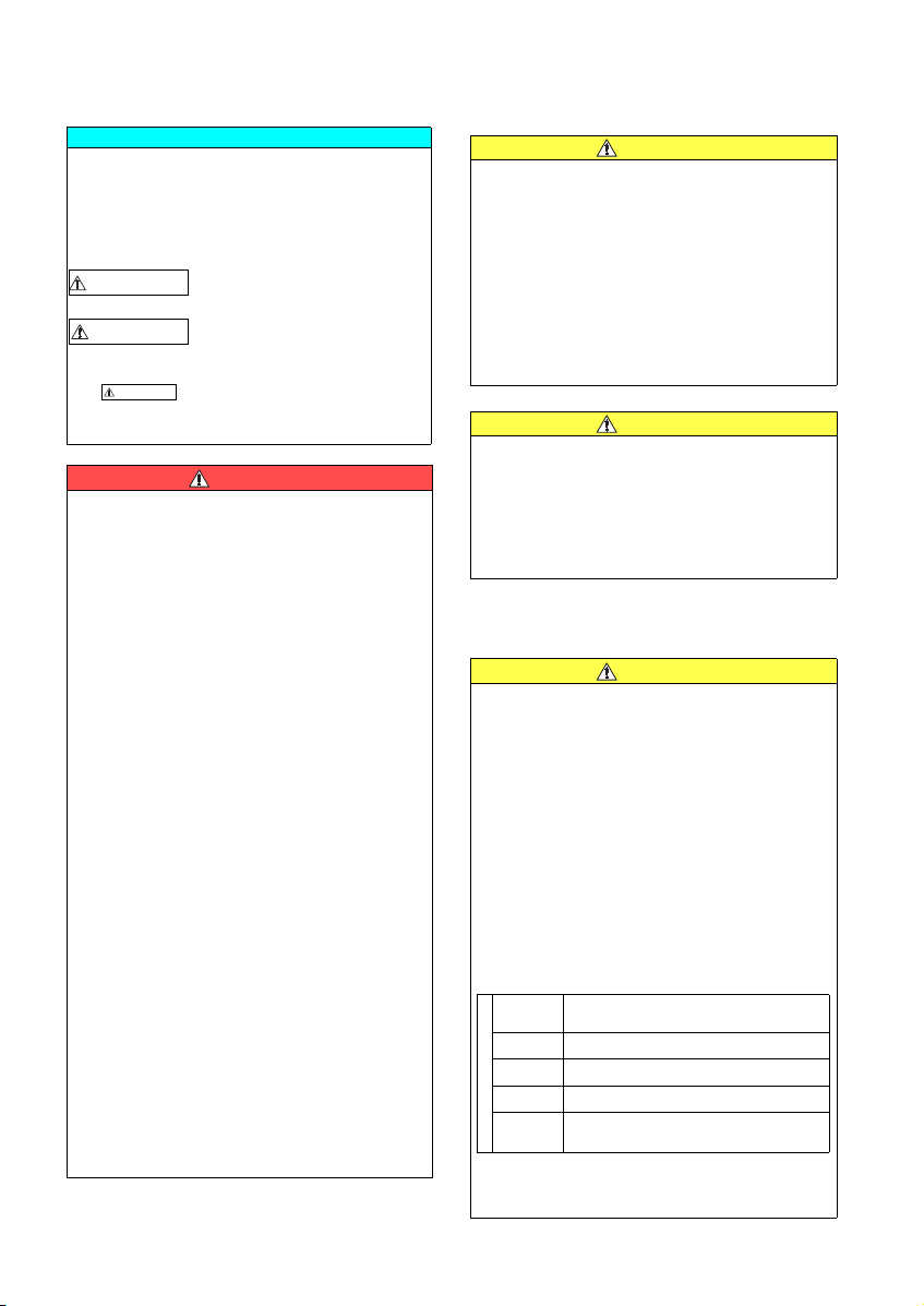
This section is specifically about safety matters
Do not attempt to install, op erate, maintain or inspect the
inverter until you have read through the Instruction Manual
(Basic) and appended documents carefully and can use the
equipment correctly. Do not use this product until you have
a full knowledge of the equipment, safety information and
instructions.
In this Instruction Manual (Basic), the safety instruction
levels are classified into "WARNING" and "CAUTION".
The level may even lead to a serious
consequence according to conditions. Both instruction
levels must be followed because these are important to
personal safety.
Incorrect handling may cause
hazardous conditions, resulting in
death or severe injury.
Incorrect handling may cause
hazardous conditions, resulting in
medium or slight inju ry, or may cause
only material damage.
1. Electric Shock Prevention
While the inverter power is ON, do not remove t he front
cover or the wiring cover. Do not run the inverter with the
front cover or the wiring cover removed. Otherwise you
may access the exposed high voltage terminals or the
charging part of the circuitry and get an electric shock.
Even if power is OFF, do not remove the front cover
except for wiring or periodic inspection. You may
accidentally touch the charged inverter circuits and get an
electric shock.
Before wiring or inspection, power must be switched OFF.
To confirm that, LED indication of the operation panel
must be checked. (It must be OFF.) Any person who is
involved in wiring or insp ection shall wait for at le ast 10
minutes after the power supply has been switched OFF
and check that there are no residual voltage using a tester
or the like. The capacitor is charged with high voltage for
some time after power OFF, and it is dangerous.
This inverter must be earthed (grounded). Earthing
(grounding) must conform to the requirements of national
and local safety regulations and electrical code (NEC section
250, IEC 61140 class 1 and other appli cable standards). A
neutral-point earthed (grounded) power supply for 400V
class inverter in compliance with EN standard must be used.
Any person who is involved in wiring or inspection of this
equipment shall be fu lly competent to do the wo rk.
The inverter must be installed before wiring. Otherwise
you may get an electric shock or be injured.
Setting dial and key operations must be performed with
dry hands to prevent an electric shock. Otherwise you
may get an electric shock.
Do not subject the cables to scratches, excessive stress, heavy
loads or pinching. Otherwise you may get an electric shock.
Do not change the cooling fan while power i s ON. It is
dangerous to change the cooling fan while power is ON.
Do not touch the printed circuit board or handle the cables
with wet hands. Otherwise you may get an electric shock.
When measuring the main circuit capacitor capacity, the
DC voltage is applied to the motor for 1s at powering OFF.
Never touch the motor terminal, etc. right after powering
OFF to prevent an electric shock.
IPM motor is a synchronous motor with high-performance
magnets embedded in the rotor. Motor terminals hold high
voltage while the motor is running even after the inverter
power is turned OFF. Before wiring or inspection, the motor
must be confirmed to be stopped. When the motor is driven by
the load in applications such as fan and blower, a low-voltage
manual contactor must be connected at the inverter's output
side, and wiring and inspection must be performed while the
contactor is open. Otherwise you may get an electric shock.
A-1
2. Fire Prevention
Inverter (Filterpack) must be installed on a nonflammable
wall without holes (so that nobody touches the inverter
heatsink on the rear side, etc.). Mounting it to or near
flammable material can cause a fire.
If the inverter has become faulty, the inverter power must
be switched OFF. A continuous flow of large current could
cause a fire.
When using a brake resistor, a sequence that will turn OFF
power when a fault signal is output must be configured.
Otherwise the brake resistor may overheat due to damage
of the brake transistor and possibly cause a fire .
Do not connect a resistor directly to the DC terminals P/+
and N/-. Doing so could cause a fire.
Be sure to perform daily and periodic inspections as specified
in the Instruction Manual. If a produ ct is used without any
inspection, a burst, breakage, or a fire may occur.
3.Injury Prevention
The voltage applied to each terminal must be the ones
specified in the Instruction Manual. Otherwise burst,
damage, etc. may occur.
The cables must be connected to the correct terminals.
Otherwise burst, damage, etc. may occur.
Polarity must be correct. Otherwise burst, damage, etc.
may occur.
While power is ON or for some time after power-OFF, do not
touch the inverter (Filte rpack) since the inverte r (Filterpack)
will be extremely hot. Doi ng so can cause burns.
4. Additional Instructions
Also the following points must be noted to prevent an
accidental failure, injury, electric shock, etc.
(1) Transportation and Mounting
The product must be transported in correct method that
corresponds to the weight. Failure to do so may lead to
injuries.
Do not stack the boxes containing inverters higher than
the number recommended.
The product must be installed to the position where
withstands the weight of the product according to the
information in the Instruction Manual.
Do not install or operate the inverter (Filterpack) if i t is
damaged or has missing parts.
When carrying the inverter, do not hold it by the front
cover or setting dial; it may fall off or fail.
Do not stand or rest heavy objects on the product.
The inverter mounting orientation must be correct.
Foreign conductive objects must be prevented from
entering the inverter (Filterpack). That includes screws and
metal fragments or other flammable substance such as oil.
Because the inverter (Filterpack) is a precision
instrument, do not dr op or subject it to impact.
The inverter (Filterpack) must be used under the following
environment conditions: Otherwise the inverter
(Filterpack) may be damaged.
1 Temperature applicable for a short time, e.g. in transit.
2 When installing the Filterpack of 11K or 15K on the rear
panel of the inverter, do not install on moving objects or
places which vibrates (exceeding 1.96m/s
2
).
Page 3
If halogen-based materials (fluorine, chlorine, bromine,
CAUTION
CAUTION
CAUTION
WARNING
CAUTION
CAUTION
CAUTION
CAUTION
iodine, etc.) infiltrate into a Mitsubishi Electric product,
the product will be damaged. Halogen-based materials are
often included in fumigant, w hich is used to steriliz e or
disinfest wooden packag es. When packaging, prev ent
residual fumigant components from being infiltrated into
Mitsubishi Electric products, or use an alternative
sterilization or disinfection method (heat disinfection,
etc.) for packaging. Sterilization of disinfection of wooden
package should also be performed before packaging the
product.
(2) Wiring
Do not install a power factor correction capacitor or surge
suppressor/capacitor type filter on the inverter output
side. These devices on the inverter output side may be
overheated or burn out.
The connection orientation of the output cables U, V, W to
the motor affects the rotation direction of the motor.
IPM motor terminals (U, V, W) hold high-voltage while the
IPM motor is running even after the power is turned OFF.
Before wiring, the IPM motor must be confirmed to be
stopped. Otherwise you may get an electric shock.
Never connect an IPM motor to the commercial power
supply. Applying the commercial power supply to input
terminals (U, V, W) of an IPM motor will burn the IPM
motor. The IPM motor must be connected with the output
terminals (U, V, W) of the inverter.
(3) Trial run
Before starting operation, each parameter must be
confirmed and adjusted. A failure to do so may cause
some machines to make unexpected motions.
(4) Usage
The IPM motor capacity must be same with the inverter
capacity. (The 0.75K inverter can be used with a one-rank
lower motor.)
Do not use multiple IPM motors with one inverter.
Any person must stay away from the equipment when the
retry function is set as it will restart suddenly after trip.
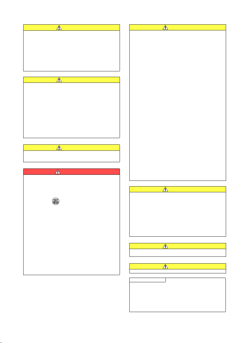
Since pressing key may not stop output depending
on the function setting status, separate circuit and switch
that make an emergency stop (power OFF, mechanical
brake operation for emergency stop, etc.) must be provided.
OFF status of the start signal must be confirmed before
resetting the inverter fault. Resetting inverter alarm with
the start signal ON restarts the motor suddenly.
Do not use an IPM motor in an application where a motor
is driven by its load and runs at a speed higher than the
maximum motor speed.
A dedicated IPM motor must be used under IPM motor
control. Do not use a synchronous motor, induction motor,
or synchronous induction motor under IPM motor control.
The inverter must be used for three-phase induction
motors or the dedicated IPM motor.
Connection of any other electrical equipment to the
inverter output may damage the equipment.
Do not modify the equipment.
Do not perform parts removal which is not instructed in this
manual. Doing so may lead to fault or damage of the product.
The electronic thermal relay function does not guarantee
protection of the motor from overheating. It is
recommended to install both an external thermal and PTC
thermistor for overheat protection.
Do not use a magnetic contactor on the inverter input for
frequent starting/stopping of the inverter. Otherwise, the
life of the inverter decreases.
The effect of electromagnetic interference must be
reduced by using an EMC filter or by other means.
Otherwise nearby electronic equipment may be affected.
Appropriate measures must be taken to suppress
harmonics. Otherwise power supply harmonics from the
inverter may heat/damag e the power factor correction
capacitor and generator.
When driving a 400V class motor by the inverter, the
motor must be an insulation-enhanced motor or measures
must be taken to suppress surge voltage. Surge voltage
attributable to the wiring constants may occur at the
motor terminals, deteriorating the insulation of the motor.
When parameter clear or all parameter clear is performed,
the required parameters must be set again before starting
operations because all parameters return to the initial value.
The inverter can be easily set for high-speed operation.
Before changing its setting, the performances of the
motor and machine must be fully examined.
Stop status cannot be hold by the inverter's brake
function. In addition to the inverter's brake function, a
holding device must be installed to ensure safety.
Before running an inverter which had been stored for a
long period, inspection and test operation must be
performed.
Static electricity in your body must be discharged before
you touch the product. Otherwise the product may be
damaged.
Do not connect an IPM motor under the general-purpose
motor control settings (initial settings). Do not use a
general-purpose motor under the IPM motor control
setting. Doing so will cause a failure.
In the system with an IPM motor, the inverter power m ust
be turned ON before closing the contacts of the contactor
at the output side.
(5) Emergency stop
A safety backup such as an emergency brake must be
provided for devices or equipment in a system to prevent
hazardous conditions in case of failure of the inverter or
an external device controlling the inverter.
When the breaker on the inverter input side trips, the
wiring must be checked for fault (short circuit), and
internal parts of the inverter for a damage, etc. The cause
of the trip must be identified and removed before turning
ON the power of the breaker.
When any protective function is activated, appropriate
corrective action must be taken, and the inverter must be
reset before resuming operation.
(6) Maintenance, inspection and parts replacement
Do not carry out a megger (insulation resistance) test on
the control circuit of the inverter. It will cause a failure.
(7) Disposal
The inverter must be treated as industrial waste.
General instruction
Many of the diagrams and drawings in this Instruction
Manual (Basic) show the inverter without a cover or partially
open for explanation. Never operate the inverter in this
manner. The cover must be always reinstalled and the
instruction in this Instru ction Manual (Basic) m ust be
followed when operating the inverter.
For more details on a dedicated IPM motor, refer to the
Instruction Manual of the dedicated IPM motor.
A-2
Page 4
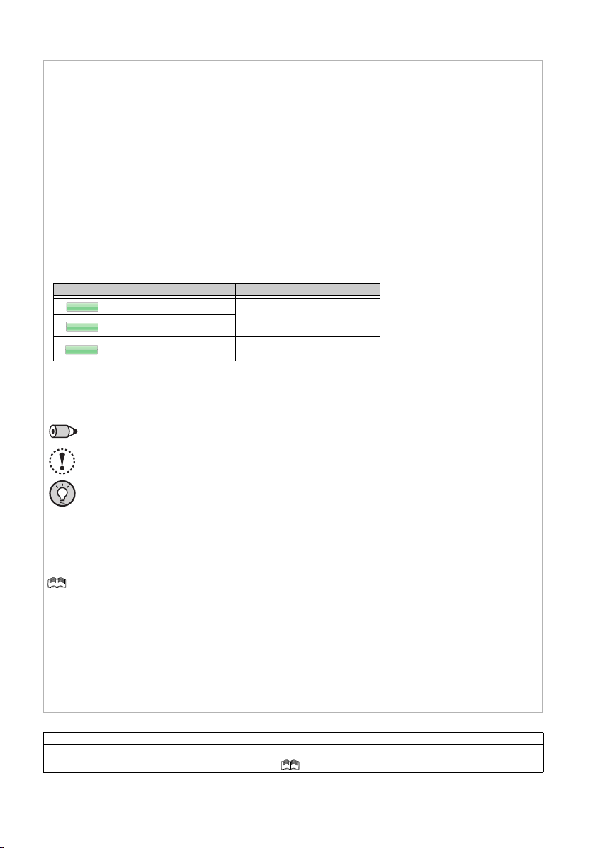
<Abbreviation>
Mark Control method Applied motor (control)
V/F control
Three-phase induction motor
(general-purpose motor control)
General-purpose magnetic
flux vector control
IPM motor control
Dedicated IPM motor
(IPM motor control)
V/FV/FV/F
GP
MFVCGP MFVCGP MFVC
IPMIPMIPM
• PU: Operation panel and parameter unit (FR-PU04
/FR-PU07)
• Inverter: Mitsubishi Electric inverter FR-F700PJ series
F700PJ: Mitsubishi Electric inverter FR-F700PJ series
•FR-
• Pr.: Parameter number (Number assigned to function)
• PU operation: Operation using the PU (operation panel/FR-PU04/FR-PU07)
• External operation: Operation using the control circuit signals
• Combined operation: Operation using both the PU (operation panel/FR-PU04/FR-PU07) and External operation
• General-purpose motor: Three-phase induction motor
• Standard motor: SF-JR
• Constant-torque motor: SF-HRCA
• Filterpack: FR-BFP2
• IPM motor: Dedicated IPM motor MM-EF(1800r/min specification)
The following marks are used to indicate the controls as below.
(Parameters without any mark are valid for all controls.)
<Trademark>
Company and product names herein are the trademarks and registered trademarks of their respective owners.
<Mark>
REMARKS:
Additional helpful contents and relations with other functions are stated.
NOTE: Contents requiring caution or cases when set functions are not activated are stated.
POINT: Useful contents and points are stated.
<Notes on descriptions in this Instruction Manual>
• Connection diagrams in this Instruction Manual appear with the control logic of the input terminals as sink logic, unless
otherwise specified. (For the control logic, refer to page 1.)
<Related document>
Refer to the Instruction Manual (Applied) for further information on the following points.
• Removal and reinstallation of the cover
• Connection of stand-alone option unit
• EMC and leakage currents
• Detailed explanation on parameters
• Troubleshooting
• Check first when you have a trouble
• Inspection items (life diagnosis, cooling fan replacement)
• Measurement of main circuit voltages, currents and powers
• For customers who are replacing the conventional model with this inverter
Harmonic suppression guideline (when inverters are used in Japan)
All models of general-purpose inverters used by specific consumers are covered by "Harmonic suppression guideline for consumers who
receive high voltage or special high voltage". (For further details, refer to Chapter 3 of the Instruction Manual (Applied).)
A-3
Page 5
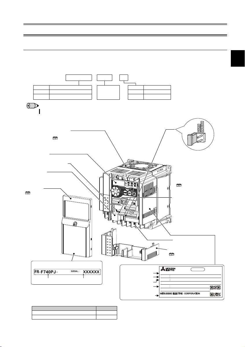
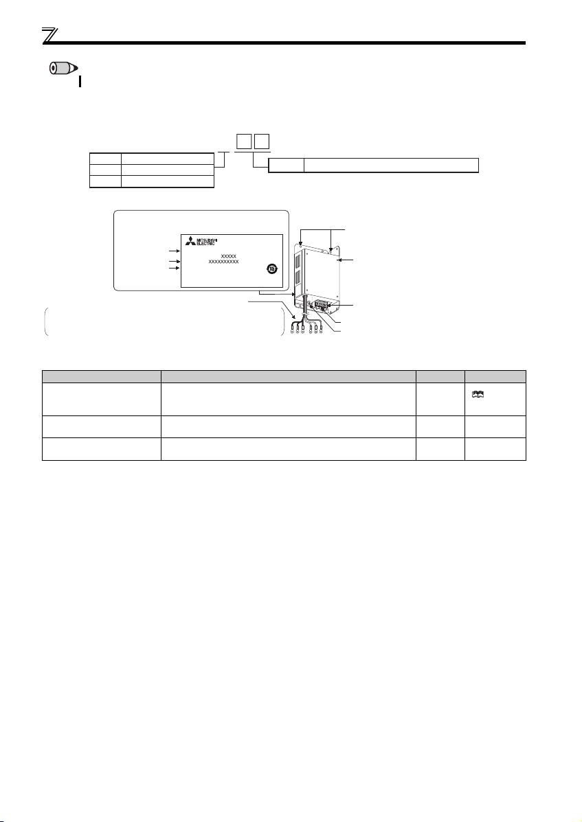
Product checking and parts identification
1
Capacity plate
Inverter model
Serial number
1.5K
Rating plate
Inverter model
Input rating
Output rating
Serial number
ᴾ
FR-F740PJ-1.5K
INPUT XXXXX
OUTPUT XXXXX
SERIAL
MADE IN JAPAN
PASS ED
INVERTER
MODEL
SAMPLE
Country of origin
Control circuit terminal block
(Refer to page 11.)
Control logic switchover jumper
connector
The jumper connector is in the sink
logic (SINK) when shipped from the
factory. Move the jumper connector
to change to the source logic
(SOURCE). Always fit the jumper
connector to the either position.
( Refer to the Instru ction Manual
(Applied).)
Combed shaped wiring cover
Refer to the Instructi on
Manual (Applied) for installation/
removal.
Main circuit terminal block
(Refer to page 11.)
Front cover
Refer to the
Instruction Manual
(Applied) for installation/
removal.
PU connector
(Refer to page 10.)
Voltage/current input switch
(Refer to page 10.)
Operation panel
(Refer to page 3.)
Cooling fan
The cooling fan is removable.
Refer to the Instruction Manual
(Applied) for installation/ removal.
Accessory
· Fan cover fixing screws (M3 35mm)
These screws are necessary for compliance
with the EU Directive.
(
Refer to page 51
.)
Capacity Quantity
1.5K to 3.7K 1
5.5K to 15K 2
1OUTLINE
1.1 Product checking and parts identification
Unpack the inverter and check the capacity plate on the front cover and the rating plate on the inverter side face to ensure that
the product agrees with your order and the inverter is intact.
(1) Inverter
Inverter model
Symbol Voltage class Represents
F720PJ Three-phase 200V class None Without
F740PJ Three-phase 400V class F With
FR- F740PJ - 1.5 K
Symbol Filterpack
the inverter
capacity [kW]
REMARKS
Filterpack (FR-BFP2) is enclosed for the inverter with Filterpack ("F" at the end of its model names marked on the packaging box.)
1
Page 6
Product checking and parts identification
FR-BFP2- H K
0.4 to 15
Represents the applicable inverter capacity (kW)
Symbol
Applicable power voltage
None
200V class
400V class
H
Installation hole
Inverter rear panel
installation screw hole
Terminal block for commercial power supply connection
Black cable: connect to terminal R, S and T of the inverter
Red cable: connect to terminal P and P1 of the inverter
Green and yellow striped cable: connect to the earth (ground) terminal
Crimp terminals for the inverter connection
Rating plate
Terminal block cover
Filterpack model
Rating
SERIAL number
MODEL
FR-BFP2-H0.4K
BKORATED
SERIAL
MITSUBISHI ELECTRIC CORPORATION
Earth (Ground) terminal
MADE IN JAPAN
REMARKS
For how to find the SERIAL num ber, refer to page 55.
(2) Filterpack
Filterpack model
Parts name and plate
Enclosed items
Name Description Quantity Refer to page
Screw for leakage current
countermeasure and spacer
Rear panel installation
L-bracket
Screw for inverter rear panel
installation
The screw size differs according to capacities. ((H)7.5K or lower: M4×14, (H)11K and (H)15K: M5×20)
When the earth leakage breaker or earth leakage relay operates
unnecessarily due to leakage current, use this screw as a
countermeasure.
Enclosed for the 5.5K or higher 1 9
Use these screws for installation of Filterpack onto the inverter rear
panel.
1 for each
4 9
Instruction
Manual (Applied)
2
Page 7
1
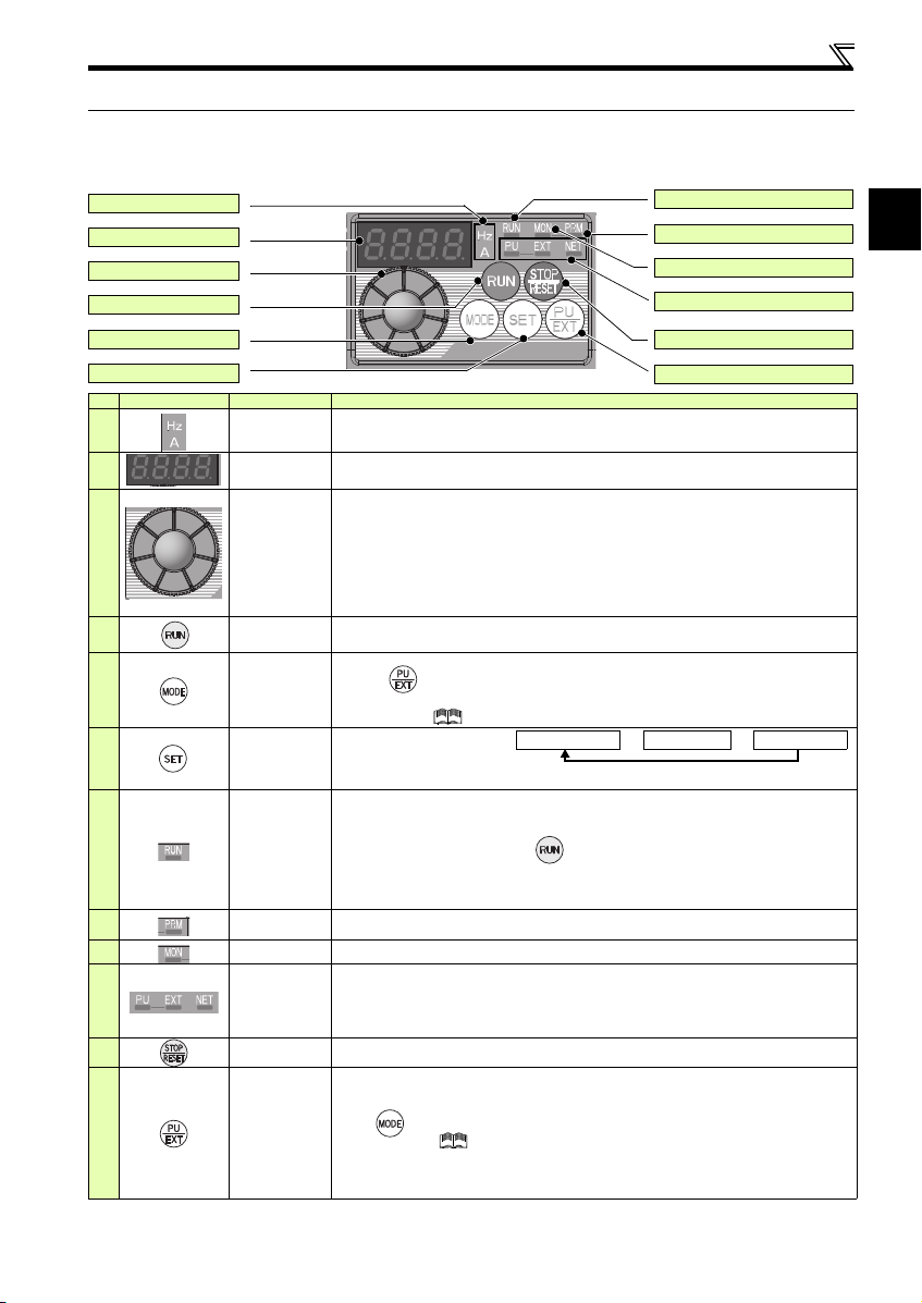
1.2 Operation panel
(a) Unit indicator
(b) Monitor (4-digit LED)
(c) Setting dial
(d) Start command
(e) MODE key
(f) SET key
(g) Operation status indicator
(h)
Parameter setting mode indicator
(i) Monitor indicator
(j) Operation mode indicat or
(k) STOP/RESET key
(l) PU/EXT key
Output frequencyOutput currentOutput voltage
*
Energy saving monitor is displayed when the
energy saving monitor is set with Pr. 52.
1.2.1 Names and functions of the operation panel
The operation panel cannot be removed from the inverter.
Operation panel
No. Component Name Description
(a)
(b)
(c)
(d)
(e)
(f)
(g)
Unit indicator
Monitor (4-digit
LED)
Setting dial
Start command Select the rotation direction in Pr. 40.
MODE key
SET key
Operation status
indicator
(h)
(i)
(j)
(k)
(l)
Parameter setting
mode indicator
Monitor indicator Lit to indicate the monitor mode .
Operation mode
indicator
STOP/RESET
key
PU/EXT key
Hz: Lit to indicate frequency. (Blinks when the set frequency monitor is displayed.)
A: Lit to indicate current.
(Both "Hz" and "A" turns OFF to indicate a value other than frequency or current.)
Shows the frequency, parameter number, etc.
(To monitor the output power, the set frequency and other items, set Pr. 52.)
The dial of the Mitsubishi Electric inverters. The setting dial is used to change the frequency
and parameter settings.
Press the setting dial to perform the following operations:
To display a control method (general-purpose motor control or IPM motor control) during th e
monitor mode
To display the set frequency when pressed for 1s or longer under PU operation mode or External/
PU combined operation mode (Pr. 79 = "3")
To display the present setting during calibration
To display a fault history number in the fault history mode
Used to switch among different setting modes.
Pressing simultaneously changes the operation mode.
Holding this key for 2 seconds locks the operation. The key lock is invalid when Pr. 161 = "0
(initial setting)." ( Refer to the Instruction Manual (Applied) .)
Used to enter a setting.
If pressed during the operation,
monitored item changes as the
following:
Lit or blinks during inverter operation.
* Lit: When the forward rotation o peration is being performed .
Slow blinking (1.4s cycle): When the reverse rotation operation is being performed.
Fast blinking (0.2s cycle): When has been pressed or the start command has been
When the frequency command is less than the starting fr equency.
When the MRS signal is being input.
Lit to indicate the parameter set ting mode.
PU: Lit to indicate the PU operation mode.
EXT: Lit to indicate the External operation mode. (EXT is lit at power-ON in the initial setting.)
NET: Lit to indicate the Network operation mode.
PU and EXT: Lit to indicate EXT/PU combined operation mode 1 and 2
All of these indicators are OFF when the command source is not a t the operation panel.
Used to stop operation commands.
Used to reset a fault when the protective function (fault) is activated.
Used to switch between the PU and External operation modes.
To use the External operation mode (operation using a separately connected frequency setting
potentiometer and start signal), press this key to light up the EXT indicator.
(Press simultaneously (0.5s), or change the Pr.79 setting to change to the combined
operation mode. ( Refer to the Instru ction Manual (Applied).)
PU: PU operation mode
EXT: External operation mode
Used to cancel the PU stop also.
*
given, but the operation cannot be made.
3
Page 8

Operation panel
Hz
A
While a fault is displayed:
The display shifts as follows by pressing : Output frequency at the fault
Output current Output voltage Energization time.
(After Energization time, it goes back to a fault display.)
Pressing the setting dial shows the fault history number.
STOP
Operation mode switchover
Parameter settingFault history Monitor/frequency setting
At power-ON (External operation mode)
PU operation mode
(output frequency monitor)
Parameter setting mode
PU Jog operation mode
Output current monitor
General-purpose
motor control
Set frequency
is displayed
Output voltage monitor
Display the
present setting
Value change
Keep pressing
the setting dial
Parameter write is completed.
Parameter and a setting value
appear alternately.
Parameter clear
Automatic
parameter setting
IPM parameter
initialization
All parameter
clear
Fault history clear
Initial value
change list
(Example)
(Example)
(After 1s)
Frequency setting has been
written and completed.
and frequency appear alternately.
[Operation for displaying fault history]
The past eight faults can be displayed using the setting dial.
(The latest fault is ended by ".".)
When no fault history exists, is displayed.
Value change
( Refer to Chapter 4 of the Instruct ion Manual (Applied).)
(Refer to page 5.)
1.2.2 Basic operation (factory setting)
4
Page 9
1
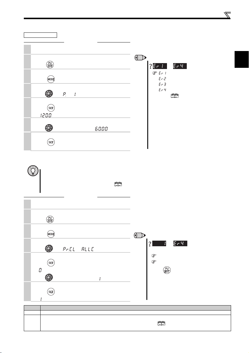
1.2.3 Changing the parameter setting value
REMARKS
is displayed...Why?
appears .... Write disable error
appears .... Write error during operation
appears .... Calibration error
appears ....Mode designation error
For details, refer to the Instruction Manual
(Applied).
The number of digits displayed on the operation
panel is four. Only the upper four digits of values can
be displayed and set. If the values to be displayed
have five digits or more including decimal places, the
fifth or later numerals cannot be displayed nor set.
(Example) For Pr. 1
When 60Hz is set, 60.00 is displayed.
When 120Hz is set, 120.0 is displayed and second
decimal place is not displayed nor set.
REMARKS
are displayed alternately ...
Why?
The inverter is not in the PU operation mode.
PU connector or USB connector is used.
1. Press . [PU] is lit and the monitor (4-digit LED)
displays "1". (When Pr. 79 = "0" (initial value))
2. Carry out operation from step 5 again.
Stop the inverter. Parameter clear is unavailable
when the inverter is running, and w ill cause the write
disable error.
Operation example C hange the Pr. 1 Maximum frequency setting.
Screen at power-ON
1.
The monitor display appears.
Operation mode change
2.
Press to choose the PU operation mode. PU indicator is lit.
Parameter setting mode
3.
Press to choose the parameter setting m ode.
Selecting the parameter number
4.
Turn until " " (Pr. 1) appears.
Reading the setting value
5.
Press to read the present set value.
" "(120.0Hz (initial value)) appears.
Changing the setting value
6.
Turn to change the set value to " " (60.00Hz).
Setting the parameter
7.
Press to set.
The parameter number and the setting value blink alternately.
1.2.4 Parameter clear/all parameter clear
POINT
Set "1" in Pr.CL Parameter clear or ALLC all parameter clear to initialize parameters. (Parameters are not cleared
when "1" is set in Pr. 77 Parameter write selection.)
Refer to the extended parameter list of the Instruction Manual (Applied) for parameters cleared with this
operation.
Screen at power-ON
1.
The monitor display appears.
Operation mode change
2.
Press to choose the PU operation mode. PU indicator is lit.
Parameter setting mode
3.
Press to choose the parameter setting m ode.
Selecting Parameter Clear (All Parameter Clear)
4.
Turn until " " (" ") appears
Selecting the setting value
Press to read the present set value.
5.
" "(initial value) appears.
Turn to change it to the set value " ".
Press to set.
6.
Press to set.
" " and Pr. CL (ALLC) indications blink alte rnately.
Setting Description
0 Clear is not executed.
1
Sets parameters back to the initial values. (Parameter clear sets back all parameters except calibration parameters, terminal
function selection parameters to the initial values.) Refer to the parameter list of the Instruction Manual (Applied) for
availability of parameter clear and all para meter clear.
Operation panel
Operation
to
Operation
and
5
Page 10
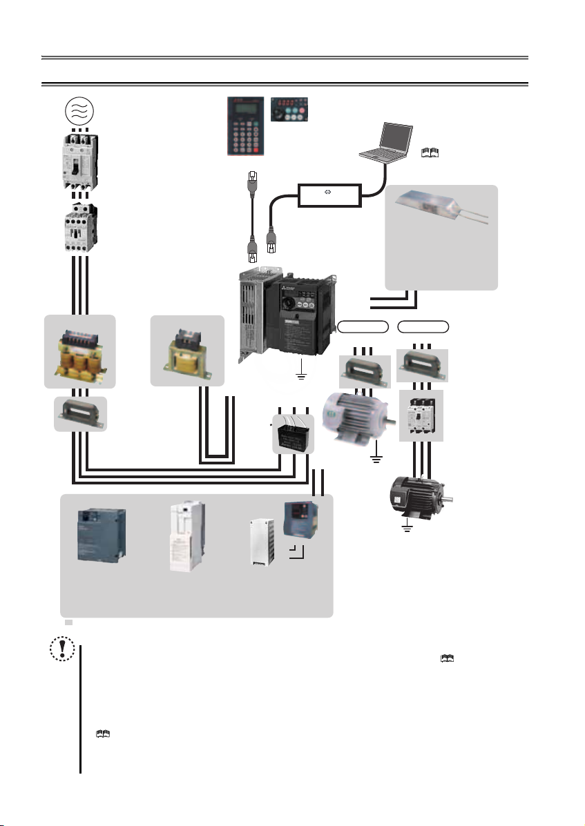
2 INSTALLATION AND WIRING
AC power supply
Use within the permissible power supply
specifications of the inverter. To ensure
safety, use a molded case circuit breaker,
earth leakage circuit breaker or magnetic
contactor to switch power ON/OFF.
Magnetic contactor (MC)
Install the magnetic contactor to ensure
safety. Do not use this magnetic contactor
to start and stop the inverter. Doing so will
cause the inverter life to be shortened.
Noise filter
(ferrite core)
(FR-BSF01,
FR-BLF)
Install a noise filter
(ferrite core) to reduce
the electromagnetic
noise generated from
the inverter.Effective
in the range from
about 0.5MHz to 5MHz.
A wire should be
wound four turns at a
maximum.
Devices connected
to the output
Do not install a power
factor correction capacitor,
surge suppressor or capacitor type filter on the output
side of the inverter. When installing a molded case
circuit breaker on the output side of the inverter,
contact each manufacturer for selection of the
molded case circuit breaker.
The regenerative braking capability
of the inverter can be exhibited fully.
Power supply harmonics
can be greatly suppressed.
High power factor
converter (FR-HC2)
Power regeneration
common converter
(FR-CV)
R/L1 S/L2T/L3
P1
P/+
P/+
N/-
P/+
PR
Great braking capability
is obtained.
Reactor (FR-HAL, FR-HEL option)
Reactors (option) must be used when
power harmonics measures are taken,
the power factor is to be improved or the
inverter is installed near a large power
supply system (500kVA or more). The
inverter may be damaged if you do not
use reactors. Select the reactor according
to the model. Remove the jumpers across
terminals P/+ and P1 to connect the DC reactor.
Noise filter (ferrite core) *
(FR-BSF01, FR-BLF)
Molded case circuit breaker (MCCB),
earth leakage circuit breaker (ELB),
or fuse
The breaker must be selected carefully
since an in-rush current flows in the
inverter at power on.
Install a noise filter (ferrite core)
to reduce the electromagnetic
noise generated from the
inverter. Effective in the range
from about 1MHz to 10MHz.
When more wires are passed
through, a more effective result
can be obtained. A wire should
be wound four turns or more.
* Not necessary if Filterpack (FR-BFP2) is used.
Earth (Ground)
To prevent an electric shock, always earth (ground)
the motor and inverter. For reduction of induction noise
from the power line of the inverter, it is recommended
to wire the earth (ground) cable by returning it to the
earth (ground) terminal of the inverter.
AC reactor (FR-HAL)
DC reactor (FR-HEL) *
Parameter unit
(FR-PU07)
Enclosure surface operation
panel (FR-PA07)
By connecting the connection cable
(FR-CB2) to the PU connector,
operation can be performed from
FR-PU07, FR-PA07.
Noise filter
(capacitor)
(FR-BIF)
P/+
P/+
PR
PR
Brake unit
(FR-BU2)
Reduces the
radio noise.
Resistor unit (FR-BR)
Discharging resistor (GZG, GRZG)
UVW
VUW
IM connection
IPM connection
Contactor
Example) No-fuse
switch (DSN type)
Install a contactor in
an application where
the IPM motor is
driven by the load
even at power-OFF
of the inverter. Do
not open or close
the contactor while
the inverter is
running (outputting).
Dedicated IPM
motor (MM-EFS,
MM-EF)
Use the
specified motor.
An IPM motor
cannot be driven
by the
commercial
power supply.
Earth
(Ground)
Generalpurpose
motor
Earth (Ground)
Inverter
FR-F700PJ
: Install this as required.
Earth
(Ground)
RS-232C - RS-485 converter is
required when connecting to PC
with RS-232C interface.
RS-485 RS-232C
Converter
(Refer to page 45.)
(Refer to page 7.)
(Refer to page 7.)
( Refer to the
Instruction Manual
(Applied).)
Brake resistor (FR-ABR,
MRS type, MYS type)
Braking capability can be improve d.
Always install a thermal relay when
using a brake resistor whose
capacity is 11K or higher.
(Refer to the Instruction Manual
(Applied).)
6
NOTE
The life of the inverter is influenced by surrounding ai r temperature. Use the product within the permissible surro unding
air temperature. This mu st be noted especiall y when the inverter is in stalled in an enclosure.
the Instruction Manual (Applied) .)
Wrong wiring might lead to damage of the inverter. The control signal lines must be kept fully away from the main
circuit to protect them from noise. (Refer to page 10.)
Do not install a power factor correction capacitor, surge suppressor or capacitor type filter on the inverter output
side. This will cause the inver ter to trip or the capacitor and surge s uppressor to be damaged. If an y of the above
devices are connected, immediately remove them.
Electromagnetic wave interference
The input/output (main circuit) of the inverter includes high frequency components, which may interfere with the
communication devices (such as AM radios) used near the inverter. In this case, install the FR-BIF optional EMC filter
(capacitor) (for use in the input side only) or FR-BSF01 or FR-BLF EMC filter (ferrite core) to minimize interference.
( Refer to Chapter 3 of the Instruction Manual (Applied).)
Refer to the Instruction Manual of each option and peripheral devices for details of peripheral devices.
An IPM motor cannot be driven by the commercial power supply.
An IPM motor is a motor with permanent magnets embedded inside. High voltage is generated at the motor terminals
while the motor is running. Before closing the contactor at the output side, make sure that the inverter power is ON
and the motor is stopped.
(
Refer to Chapter 3 of
Page 11
Peripheral devices
2
Front cover
Front cover
Front cover
Wiring cover Wiring cover
FR-F720PJ-0.4K, 0.75K FR-F720PJ-1.5K to 3.7K
FR-F740PJ-0.4K to 3.7K
FR-F720PJ-5.5K or higher
FR-F740PJ-5.5K or higher
2.1 Peripheral devices
Check the inverter model of the inverter you purchased. Appropriate peripheral devices must be selected according to the capacity.
Refer to the following list and prepare appropriate peripheral devices.
Motor
Inverter Model
Vol tag e
FR-F720PJ-0.4K 0.4 5A 5A S-T10 S-T10
FR-F720PJ-0.75K 0.75 10A 5A S-T10 S-T10
FR-F720PJ-1.5K 1.5 15A 10A S-T10 S-T10
FR-F720PJ-2.2K 2.2 20A 15A S-T10 S-T10
FR-F720PJ-3.7K 3.7 30A 30A S-T21 S-T10
FR-F720PJ-5.5K 5.5 50A 40A S-T35 S-T21
200V class
FR-F720PJ-7.5K 7.5 60A 50A S-T35 S-T35
FR-F720PJ-11K 11 75A 75A S-T35 S-T35
FR-F720PJ-15K 15 125A 100A S-T50 S-T50
FR-F740PJ-0.4K 0.4 5A 5A S-T10 S-T10
FR-F740PJ-0.75K 0.75 5A 5A S-T10 S-T10
FR-F740PJ-1.5K 1.5 10A 10A S-T10 S-T10
FR-F740PJ-2.2K 2.2 15A 10A S-T10 S-T10
FR-F740PJ-3.7K 3.7 20A 15A S-T10 S-T10
FR-F740PJ-5.5K 5.5 30A 20A S-T21 S-T12
400V class
FR-F740PJ-7.5K 7.5 30A 30A S-T21 S-T21
FR-F740PJ-11K 11 50A 40A S-T21 S-T21
FR-F740PJ-15K 15 60A 50A S-T35 S-T21
Assumes the power supply voltage is for a dedicated IPM motor or of a Mitsubishi Electric 50Hz 4-pole standard motor.
Select an MCCB according to the power supply capacity.
Install one MCCB per inverter.
For the use in the United States or Canada, refer to page 54, and select an appropriate fuse or molded case circuit
breaker (MCCB).
Magnetic contactor is selected based on the AC-1 class. The electrical durability of magnetic contactor is 500,000 times. When the magnetic contactor is
used for emergency stop during motor driving, the electrical durability is 25 times.
If using an MC for emergency stop during motor driving, select an MC regarding the inverter input side current as JEM1038-AC-3 class rated current. When
using an MC on the inverter output side for commercial-power supply operation switching using a general-purpose motor, select an MC regarding the motor
rated current as JEM1038-AC-3 class rated current.
Output
(kW)
NOTE
When the inverter capacity is larger than the motor capacity, select an MCCB and a magnetic contactor according to the inverter model,
and cable and reactor according to the motor output.
When the breaker on the inverter input side trips, check for the wiring fault (short circuit), damage to internal parts of the inverter, etc.
Identify the cause of the trip, then remove the cause and power ON the breaker.
2.2 Installation of the inverters and precautions
Molded Case Circuit Breaker (MCCB)
or Earth Leakage Circuit Breaker (ELB)
(NF or NV type)
Reactor or Filterpack Connection Reactor or Filterpack Connection
Without With Without With
Magnetic Contactor (MC)
MCCB INV
MCCB INV
M
M
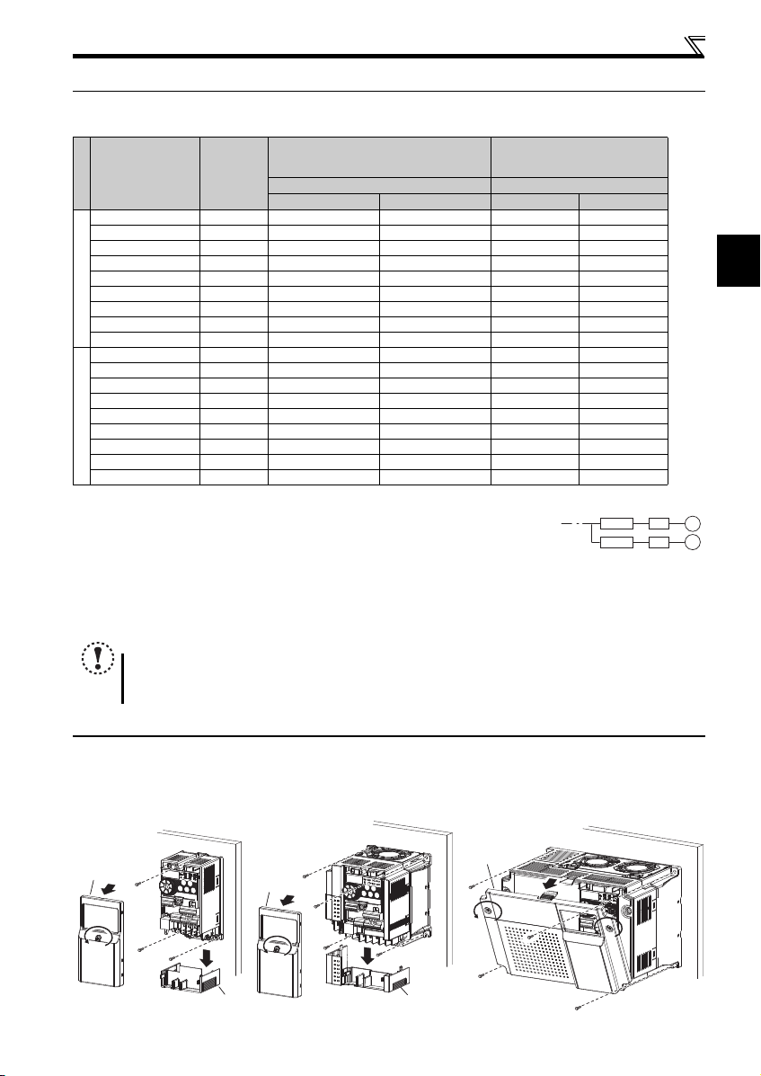
2.2.1 Installation of the inverter (without Filterpack)
Enclosure surface mounting
Remove the front cover and wiring cover to mount the inverter to the surface. (Remove the covers in the directions of the arrows.)
7
Page 12
Installation of the inverters and precautions
10cm or more
10cm or more
Measurement
position
Measurement
position
5cm
5cm
5cm
-10 C to +50 C
(non-freezing)
1cm or
more
∗1, ∗2
1cm or
more
∗1, ∗2
1cm or
more
∗1
FR-F720PJ-1.5K to 3.7KFR-F720PJ-0.4K to 0.75K
FR-F740PJ-0.4K to 3.7K
Screw for inverter rear
panel installation
Screw for inverter rear
panel installation
Front cover
Front cover
Wiring cover
Wiring cover
Screw for inverter rear
panel installation
Screw for inverter rear
panel installation
L-bracket installation screw
Screw for inverter
rear panel installation
Rear panel installation L-bracket
Screw for inverter rear panel installation
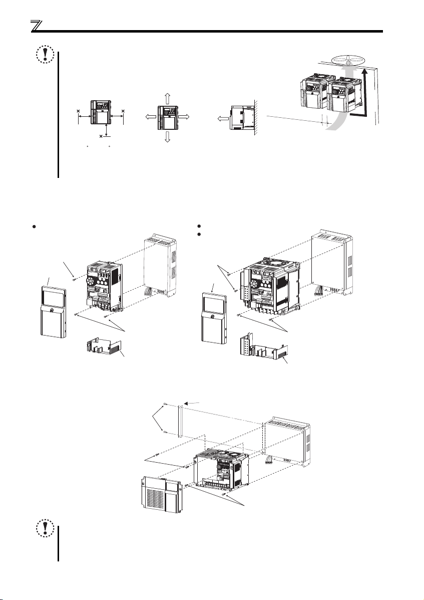
NOTE
When encasing multiple inverters, install them in parallel as a cool ing
measure.
Install the inverter vertically.
For heat dissipation and maintenance, allow minimum clearance shown
in the figures below from the inverter to the other devices and to the
inner surface of the enclosure.
Allow 5cm or more clearance for 5.5K or higher.
When using the inverters at the surrounding air temperature of 40C or less, the inverters can be installed without any clearance between
them (0cm clearance).
2.2.2 Installation of the inverter and Filterpack (for rear panel installation)
<0.4K to 3.7K>
Remove the front cover and wiring cover to attach the inverter.
Vertical
<5.5K to 15K>
Remove the L-bracket installation screws from Filterpack (two for the 7.5K or lower, three for the 11K or higher), and attach
the included L-bracket to Filterpack with these screws. Remove the front cover to attach the inverter.
8
NOTE
When encasing multiple inverters, install them in parallel as a cooling measure.
Install the inverter (Filterpack) vertically.
When installing the Filterpack to the inverter, use the included installation screws for the inverter rear panel.
Using a longer screw may damage the Filterpack.
Side-by-side installation is not available for Filter packs.
Page 13
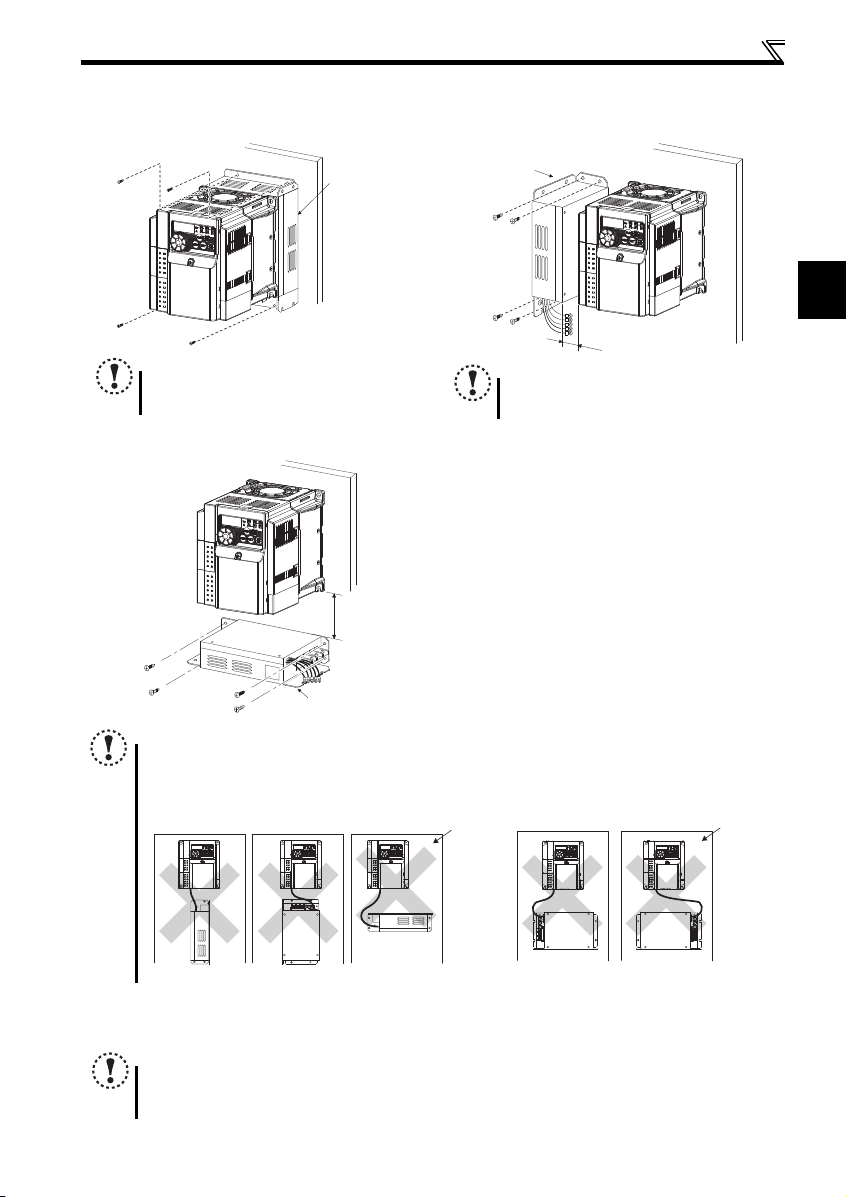
Installation of the inverters and precautions
2
Filterpack
NOTE
When installing Filterpack of 11K or 15K on the rea r
panel of the inverter, do not install on mo ving objects
or places which vibrates (exceeding 1.96m/s
2
).
Filterpack
1cm or more
NOTE
To release heat of the inverter and Filterpack,
leave clearance of 1 cm or more when installing
the inverter and Filterpack.
Filterpack
10cm or more
<Invert installation of Filterpack><Sideway installation of Filterpack>
Enclosure
2.2.3 Installation of Filterpack
The following installations are recommended for Filterpack and the inverter. For wiring of Filterpack and the inverter, refer to
Rear panel installation Side panel installation
Underneath installation
page 13
.
NOTE
Install Filterpack with the wiring portion facing right.
Underneath installation is not available for 11K and 15K.
To release heat, leave clearance of 10cm or more between the inverter and Filterpack.
To prevent malfunctions and damages, never perform installations in the following manners. Only install according to
the recommended mounting methods.
2.2.4 Environment
Before installation, check that the environment meets the specifications on page 46.
NOTE
Install the inverter on a strong surface securely and vertically with bolts.
Leave enough clearances and take cooling measures.
Avoid places where the inverter is subjected to direct sunlight, high temperature and high humidity.
Install the inverter on a nonflammable wall su rface.
Enclosure
9
Page 14
2.3 Wiring
Earth
(Ground)
Motor
M
Earth (Ground)
Three-phase
AC power
supply
MCCB MC
R/L1
P1 P/+
PR
N/-
S/L2
T/L3
U
V
W
Earth
(Ground)
*7 Brake resistor (FR-ABR, MRS type, MYS
type)
Install a thermal relay to prevent an
overheat and burnout of the brake resistor.
Always install a thermal relay when using
a brake resistor whose capacity is 11K or
higher.
*8 It is not necessary when
calibrating the indicator
from the operation panel.
Forward
rotation start
Reverse
rotation start
Middle
speed
High
speed
Terminal 4
input selection
Control input signals (No voltage input allowed)
24VDC power supply
(Common for external power supply transistor)
Contact input common
STR
STF
RH
RM
AU
SD
PC
Relay output
Running
Open collector output
Open collector output common
Sink/source common
RUN
SE
A
B
C
Frequency setting signals (Analog)
2 0 to 5VDC
10(+5V)
2
3
1
4 4 to 20mADC
Frequency
setting
potentiometer
1/2W1kΩ
Terminal 4
input
(Current
input)
(+)
(-)
5(Analog common)
*5 It is recommended to
use 2W1kΩ when the
frequency setting signal
is changed frequently.
*5
*3 When using terminals
PC-SD as a 24VDC
power supply, take
care not to short across
terminals PC and SD.
PU
connector
*2. DC reactor (FR-HEL)
When connecting a DC reactor, remove the
jumper across P1 and P/+.
Control circuit terminal
Main circuit terminal
Sink logic
Jumper
*2
*7
*3
*4
*6
The function of these
terminals can be
changed to the reset
signal, etc. with the input
terminal assignment
(Pr. 178 to Pr. 182)
.
Multi-speed selection
Terminal functions vary by
Pr. 190 RUN terminal function
selection
Terminal functions vary
by Pr. 192 A,B,C terminal
function selection
SINK
SOURCE
VI
*6
0 to 5VDC
(0 to 10VDC)
0 to 10VDC
*6 Terminal input specifications can be changed by analog
input specifications switchover (Pr. 267). Set the
voltage/current input switch in the "V" position to select
voltage input (0 to 5V/0 to10V) and "I" (initial value) to
select current input (4 to 20mA).
To use terminal 4 (initial setting is current input), turn
ON AU signal.
Voltage/current
input switch
Main circuit
Control circuit
R
Relay output
(Fault output)
Brake unit
(Option)
FM
SD
Indicator
(Frequency meter,
etc.)
+
-
Moving-coil
type 1mA
full-scale
Calibration resistor
*8
*9
*4 Terminal input specifications
can be changed by analog
input specifications
switchover (Pr. 73).
Terminal 10 and terminal 2
are used as PTC input
terminal (Pr. 561).
With Filterpack
Three-phase
AC power
supply
MCCB MC
R/L1
P1
P/+
S/L2
T/L3
Earth (ground)
*1 Remove the jumper
across the terminals P1
and P/+ to install
Filterpack.
Jumper
*1
R0
S0
T0
P1
P
Filterpack
FR-BFP2
GND
R
S
T
*9 Operation and parameter setting can be
done from the parameter unit
(FR-PU07) and the enclosure surface
operation panel (FR-PA07).
(Use the option cable (FR-CB2 ).)
RS-485 communication can be utilized
from a personal computer and other
devices.
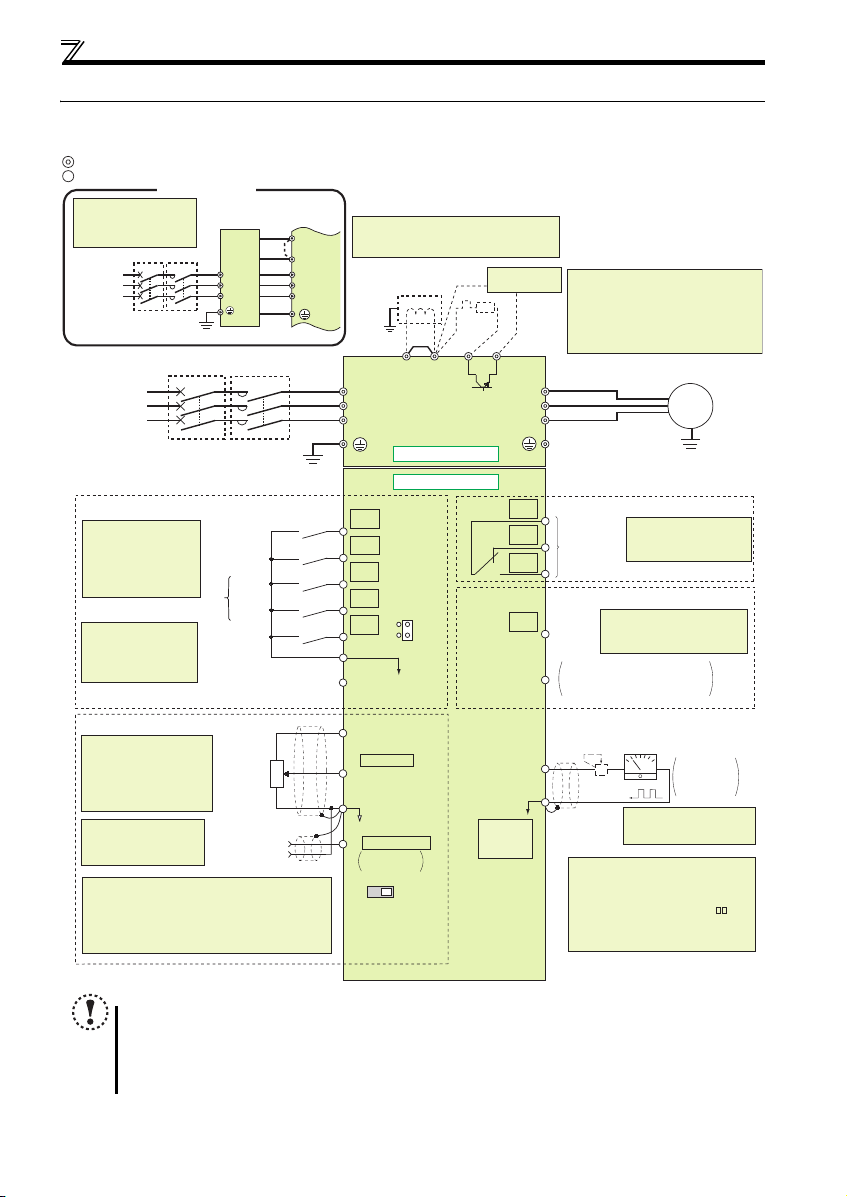
2.3.1 Terminal connection diagram
Wiring
10
NOTE
To prevent a malfunction caused by noise, separate the signal cables more than 10cm from the power cables. Also
separate the main circuit wire of the input side and the output side.
After wiring, wire offcuts must not be left in the inverter.
Wire offcuts can cause an alarm, failure or malfunction. Always keep the inverter clean. When drilling mounting holes
in an enclosure etc., take ca re not to allow chips and othe r foreign matter to ent er the inverter.
Terminals S1, S2, SC, and SO are for manufacturer setting. Do not remove the shortening wires across terminals S1
and SC and terminals S2 and SC.
Page 15
Wiring
2
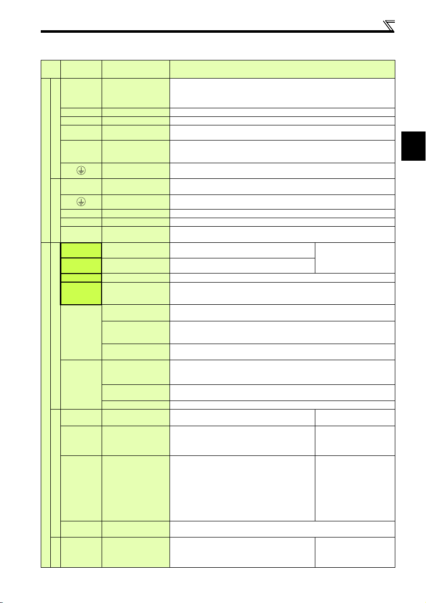
2.3.2 Terminal specifications
Terminal
Typ e
Symbol
R/L1, S/L2,
T/L3
U, V, W Inverter output
P/+, PR Brake resistor connection
P/+, N/- Bra ke unit connection
Inverter
P/+, P1
Main circuit
R0, S0, T0
R, S, T Inverter power supply
Filterpack
P, P 1 DC reactor terminal
GND
STF Forward rotation start
STR Reverse rotation start
RH, RM Multi-speed s election
AU Terminal 4 input selection
SD
Contact input
PC
10
Control circuit/Input signal
2
4
Frequency setting
5
10
2
Thermistor
Terminal Name Terminal Specification
Connect to the commercial power supply.
AC power input
DC reactor (Filterpack)
connection
Earth (Ground)
Commercial power
supply input
Earth (Ground)
Inverter earth (ground)
connection
Contact input common
(sink) (initial setting)
External transistor
common (source)
24VDC power supply
common
External transistor
common (sink)
(initial setting)
Contact input common
24VDC power supply
Frequency setting power
Frequency setting
(voltage)
Frequency setting
(current)
Frequency setting
common
PTC thermistor input
(source)
supply
Do not connect anything to these terminals when using the high power factor converter (F RHC2) or power regeneration common converter (FR-CV).
To use Filterpack, connect the R, S, and T cables of Filterpack.
Connect a three-phase squirrel-cage moto r or a dedicated IPM motor.
Connect a brake resistor (FR-ABR, MRS type, MYS type) across terminals P/+ and PR.
Connect the brake unit (FR-BU2), power regeneration common conve rter (FR-CV) or high
power factor converter (FR-HC2).
Remove the jumper across terminals P/+ and P1 and connect a DC reactor.
To use Filterpack, remove the jumper across the terminals P/+ and P1, then connect the P and
P1 cables of Filterpack.
For earthing (grounding) the inverter chassis. Must be earthed (g rounded).
To use Filterpack, connect the GND cable of Filterpack.
Connect to the commercial power supply.
For earthing (grounding) the Filterpack. Must be earthed (grounded) .
Connect to R/L1, S/L2, and T/L3 of the inverter.
Remove the jumper across terminals
Connect to the earth (ground) terminal of the inverter.
Turn ON the STF signal to start forward rotation and turn it
OFF to stop.
Turn ON the STR signal to start reverse rotation and turn it
OFF to stop.
Multi-speed can be selected according to the combination of RH and RM signals.
The terminal 4 function is available only when the AU signal is ON. (the operation with the
frequency setting signal of 4 to 20mA DC is available)
Turning ON the AU signal disables the terminal 2 (voltage input) function.
Common terminal for contact input terminal (sink logic) and t erminal FM.
Connect this terminal to the power supply common terminal of a transistor output (open
collector output) device, such as a programmable controller, in the source logic to avoid
malfunction by undesirable current.
Common output terminal for 24VDC 0.1A power supply (PC terminal).
Isolated from terminals 5 and SE.
Connect this terminal to the power supply common terminal of a transistor output (open
collector output) device, such as a programmable controller, in the sink logic to avoid
malfunction by undesirable current.
Common terminal for contact input terminal (source logic).
Can be used as 24VDC 0.1A power supply.
Used as power supply when connecting potentiometer for
frequency setting (speed setting) from outside of the inverter.
Inputting 0 to 5VDC (or 0 to 10V) provides the maximum
output frequency at 5V (10V) and makes input and output
proportional. Use Pr. 73 to switch between input 0 to 5VDC
input (initial setting) and 0 to 10VDC.
Inputting 4 to 20mADC (or 0 to 5V, 0 to 10V) provides the
maximum output frequency at 20mA and makes input and
output proportional. The input signal to terminal 4 is valid
only when the AU signal is ON (terminal 2 input is invalid).
Use Pr. 267 to switch from among input 4 to 20mA (initial
setting), 0 to 5VDC and 0 to 10VDC. Set the voltage/current
input switch in the "V" position to select voltage input (0 to
5V/0 to 10V).
Frequency setting signal (terminal 2 or 4) common terminal. Do not earth (ground).
For connecting PTC thermistor output.
When PTC thermistor protection is valid (Pr. 561 "9999"),
terminal 2 is not available for frequency setting.
P/+
and P1, and connect to th e terminals
When the STF and STR signals
are turned ON simultaneously,
the stop command is given.
5VDC
permissible load current 10mA
Input resistance10k1k
Permissible maximum voltage
20VDC
Current input:
Input resistance 2495
Maximum permissible current
30mA
Voltage input:
Input resistance10k 1k
Permissible maximum voltage
20VDC
Adaptive PTC thermistor
specification
Heat detection resistance :
500 to 30k (Set by Pr. 561)
P/+
and P1 of the inverter.
11
Page 16

Wiring
Terminal
Typ e
Symbol
A, B, C
Relay
RUN Inverter running
Open collector
SE
Control circuit terminal/Output signal
FM For meter
Pulse
— PU connector
Communication
NOTE
To change the input specification for terminal 4, set Pr. 267 and the voltage/current input switch correctly, then input
the analog signal relevant to the setting. Applying a voltage with voltage/current input switch in "I" position (current
input is selected) or a current with switch in "V" position (voltage input is selected) could cause component damage
of the inverter or analog circuit of output devices.
Connecting the power supply to the inverter output terminals (U, V, W) will damage the inverter. Do not perform such
wiring.
indicates that terminal functions can be selected using Pr. 178 to Pr. 182, Pr. 190 and Pr. 192 (I/O terminal function
selection).
The terminal names and functions shown here are the initial settings.
Terminals S1, S2, SC, and SO are for manufacturer setting. Do not connect anything to these.
Doing so may cause an inverter failure. Do not remove the shortening wires across terminals S1 and SC and
terminals S2 and SC. Removing either shortening wire disables the inverter operation.
Terminal Name Terminal Specification
1 changeover contact output indicates that the inverter protectiv e function has activated and
Relay output
(fault output)
Open collector output
common
the output stopped.
Fault: discontinuity across B-C (continuity across A-C),
Normal: continuity across B-C (discontinuity across A-C)
Contact capacity:230VAC 0.3A (power factor =0.4) 30VDC 0.3A
Switched Low when the inverter output frequency is equal to
or higher than the starting frequency (initial value 0.5Hz).
Switched High during stop or DC injection brake operation.
(Low is when the open collector output transistor is ON
(conducts). High is when the transistor is OFF (does not
conduct).)
Common terminal of terminal RUN.
Selected one e.g. output frequency from monitored items.
(Not output during inverter reset.)
The output signal is proportional to the magnitude of the
corresponding monitored item.
With the PU connector, communication can be established through RS-485.
Conforming standard: EIA-485 (RS-485)
Transmission format: Multidrop link
Communication speed: 4800 to 38400bps
Overall length: 500m
Permissible load 24VDC
(maximum 27VDC) 0.1A
(a voltage drop is 3.4V maximum
when the signal is ON)
Permissible load current 1mA
1440 pulses/s at full scale
12
Page 17
Wiring
2
MotorPower supply
N/-
P/+ PR
M
R/L1 S/L2 T/L3
Jumper
Motor
Power supply
N/-
P/+
PR
M
R/L1 S/L2 T/L3
Jumper
N/-
P/+
PR
R/L1 S/L2 T/L3
Jumper
MotorPower supply
M
Motor
M
N/-
P/+
PR
R/L1 S/L2 T/L3
Earth
(Ground)
R0 S0 T0
Power supply
Filterpack
(FR-BFP2)
Inverter
Jumper
Connection example with FR-F740PJ-11K
TSRP1 P
GND
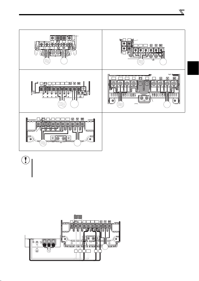
2.3.3 Terminal arrangement of the main circuit terminal, power supply and the motor wiring
Three-phase 200V/400V class
FR-F720PJ-0.4K to 0.75K FR-F720PJ-1.5K to 3.7K
FR-F740PJ-0.4K to 3.7K
FR-F720PJ-5.5K, 7.5K
FR-F740PJ-5.5K, 7.5K
N/-
Jumper
P/+ PR
R/L1 S/L2 T/L3
FR-F720PJ-11K, 15K
M
FR-F740PJ-11K, 15K
N/-
Jumper
Power supply
NOTE
For the inverters without Filterpacks, make sure the power cables are connected to R/L1, S/L2, and T/L3. (Phase does
not need to be matched.) Never connect the power cable to the U, V, and W of the inverter. Doing so will damage the
inverter.
Connect the motor to U, V, and W. Turning ON the forward rotation switch (signal) at this time rotates the motor
counterclockwise when viewed from the load shaft.
2.3.4 Wiring of the inverter and Filterpack
Perform wiring of the inverter and Filterpack in the following procedure.
(1) Connect the commercial power supply to terminals R0, S0 and T0 of the Filterpack.
(2) Connect the earthing cable (green and yellow striped cable) of the Filterpack to the inverter earth (ground) terminal.
(3)
Connect the power supply cable (black cable) of the Filterpack to terminals R, S and T. (Phase sequence need not be matched.
Remove the jumper across terminals P and P1 of the inverter, and connect the P and P1 cables (red cable) of the Filterpack
(4)
(5) Connect the motor cable to the inverter output terminals (U, V, W). (Match the phase sequence)
Power supply Motor
R/L1 S/L2 T/L3
P/+
PR
M
Motor
)
.
13
Page 18
Wiring
3 × wire resistance [mΩ/m] × wiring distance [m] × current [A]
1000
NOTE
For the inverters with Filterpacks, make sure the power cables are connected to terminals R0, S0, and T0 of the
Filterpack (FR-BFP2). (Phase sequence does not need to be matched)
Never connect the power cable to the U, V, W of the inverter. Doing so will damage the inverter.
When connecting Filterpack, make sure that the jumper across terminals P and P1 of the inverter is removed.
Connect the GND cable of Filterpack to the earth (ground) terminal of the inverter.
Use the earth (ground) terminal of Filterpack for earthing (grounding). The inverter is earthed (grounded) through
Filterpack.
Connect the Filterpack terminals P and P1 to the inverter terminals of P/+ and P1, respectively. Improper connections
may damage the inverter.
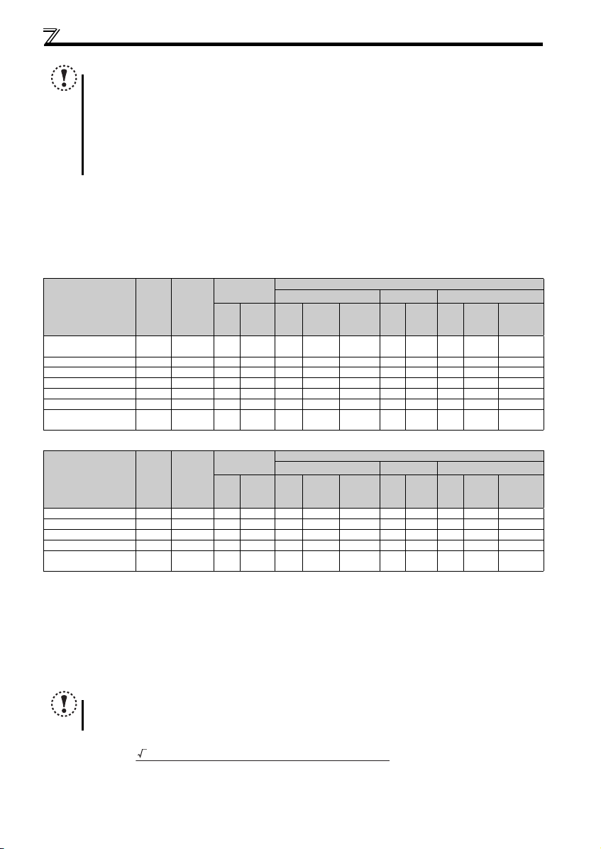
2.3.5 Cables and wiring length
(1) Applicable cable size
Select the recommended cable size to ensure that a voltage drop will be 2% at maximum.
If the wiring distance is long between the inverter and motor, a main circuit cable voltage drop will cause the motor torque to
decrease especially at the output of a low frequency.
The following table indicates a selection example for the wiring length of 20m.
Three-phase 200V class (when input power supply is 220V)
Ter min al
Applicable Inverter
Model
FR-F720PJ-0.4K to
0.75K
FR-F720PJ-1.5K, 2.2K M4 1.5 2-4 2-4 2 2 2 14 14 2.5 2.5 2.5
FR-F720PJ-3.7K M4 1.5 5.5-4 5.5-4 3.5 3.5 3.5 12 12 4 4 4
FR-F720PJ-5.5K M5 2.5 5.5-5 5.5-5 5.5 5.5 5.5 10 10 6 6 6
FR-F720PJ-7.5K M5 2.5 14-5 8-5 14 8 5.5 6 8 16 10 6
FR-F720PJ-11K M5 2.5 14-5 14-5 14 14 8 6 6 16 16 1 6
FR-F720PJ-15K
Tightening
Screw
Tor que
Size
N·m
M3.5 1.2 2-3.5 2-3.5 2 2 2 14 14 2.5 2.5 2.5
M6
4.4
(M5)
(2.5)
Terminal
R/L1
S/L2
T/L3
22-6
(14-5)
Crimp
U, V, W
(14-5)
HIV Cables, etc. (mm2)
R/L1
S/L2
T/L3
22-6
22 22 14 4 4 25 25 16
U, V, W
Earthing
Three-phase 400V class (when input power supply is 440V)
Ter min al
Applicable Inverter
Model
FR-F740PJ-0.4K to 3.7K M4 1.5 2-4 2-4 2 2 2 14 14 2.5 2.5 2.5
FR-F740PJ-5.5K M4 1.5 5.5-4 2-4 3.5 2 3.5 12 14 4 2.5 4
FR-F740PJ-7.5K M4 1.5 5.5-4 5.5-4 3.5 3.5 3.5 12 12 4 4 4
FR-F740PJ-11K M4 1.5 5.5-4 5.5-4 5.5 5.5 5.5 10 10 6 6 10
FR-F740PJ-15K
The cable size is that of the cable (HIV cable (600V class 2 vinyl-insulated cable) etc.) with continuous maximum permissible temperature of 75°C. Assumes
that the surrounding air temperature is 50°C or less and the wiring distance is 20m or less.
The recommended cable size is that of the cable (THHW cable) with continuous maximum permissible temperature of 75°C. Assumes that the surrounding
air temperature is 40°C or less and the wiring distance is 20m or less.
(For the use in the United States or Canada, refer to page 54.)
The recommended cable size is that of the cable (PVC cable) with continuous maximum permissible temperature of 70°C. Assumes that the surrounding air
temperature is 40°C or less and the wiring distance is 20m or less.
(Selection example for use mainly in Europe.)
The terminal screw size indicates the terminal size for R/L1, S/L2, T/L3, U, V, W, PR, P/+, N/-, P1 and a screw for earthing (grounding). Terminal screw size
for Filterpack (FR-BFP2) is same as the terminal screw size for the inverter.
Screw size for earthing (grounding) the FR-F720PJ-15K is indicated in parenthesis.
Screw sizes of the terminals R0, S0, and T0 and the earthing terminal of FR-BFP2-H15K are indicated in parenthesis.
For the earthing cable size for Filterpack, use the same size as for the inverter.
Screw
Size
M5
(M6)
Tightening
Tor que
N·m
2.5
(4.4)
Terminal
R/L1
S/L2
T/L3
8-5
(14-6)
Crimp
U, V, W
(14-6)
HIV Cables, etc. (mm2)
R/L1
S/L2
T/L3
8-5
88 5.5881010 10
U, V, W
Earthing
NOTE
Tighten the terminal screw to the specified torque. A screw that has been tightened too loosely can cause a short circuit or
malfunction. A screw that has been tightened too tightly can cause a short circuit or malfunction due to the unit breakage.
Use crimp terminals with insulation sleeve to wire the power supply and motor.
The line voltage drop can be calculated by the following formula:
Line voltage drop [V]=
Use a larger diameter cable when the wiring distance is long or when it is desired to decrease the voltage drop (torque
reduction) in the low speed range.
cable
cable
Cable Size
AWG
R/L1
S/L2
U, V, W
T/L3
Cable Size
AWG
R/L1
S/L2
U, V, W
T/L3
PVC Cables, etc. (mm2)
R/L1
S/L2
T/L3
PVC Cables, etc. (mm2)
R/L1
S/L2
T/L3
U, V, W
U, V, W
Earthing
cable
Earthing
cable
14
Page 19
Wiring
2
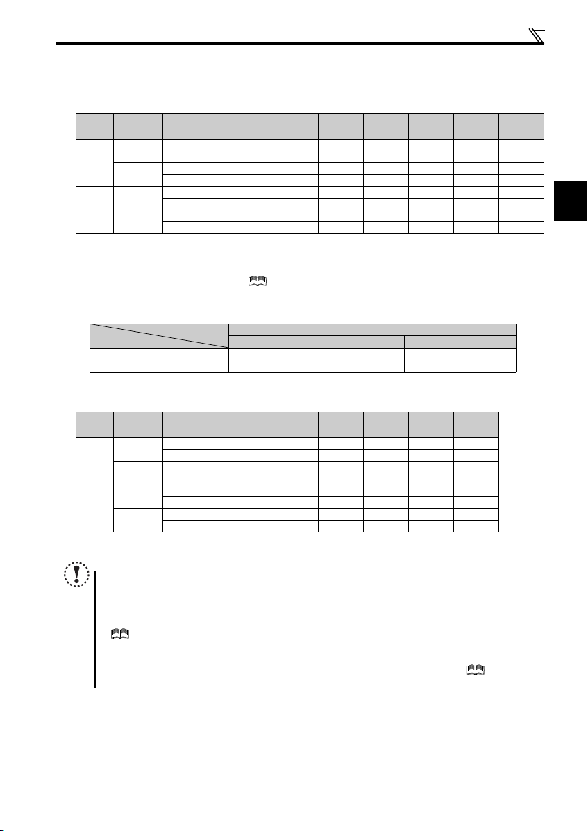
(2) Total wiring length
Under general-purpose motor control
Connect one or more general-purpose motors within the total wiring length shown in the following table.
Vol tag e
Cable Type
Class
Unshielded
200V
Shielded
Unshielded
400V
Shielded
When driving a 400V class motor by the inverter, surge voltages attributable to the wiring constants may occur at the
motor terminals, deteriorating the insulation of the motor.
If that is the case, use a "400V class inverter-driven insulation-enhanced motor" and set frequency in Pr. 72 PWM
frequency selection according to wiring length. (
class motor with an inverter.)
Pr. 72 PWM frequency selection Setting
(carrier frequency)
cable
cable
cable
cable
1 (1kHz) or lower 300m 500m 500m 500m 500m
2 (2kHz) or higher 200m 300m 500m 500m 500m
1 (1kHz) or lower 75m 100m 100m 100m 100m
2 (2kHz) or higher 50m 75m 100m 100m 100m
1 (1kHz) or lower 200m 200m 300m 500m 500m
2 (2kHz) or higher 30m 100m 200m 300m 500m
1 (1kHz) or lower 50m 50m 75m 100m 100m
2 (2kHz) or higher 10m 25m 50m 75m 100m
0.4K 0.75K 1.5K 2.2K
Refer to Chapter 3 in the Instruction Manual (Applied) to drive a 400V
3.7K
or Higher
50m or less 50m to 100m Exceeding 100m
Wiring Length
Pr. 72 PWM frequency selection Setting
(carrier frequency)
15 (14.5kHz) or less 8 (8kHz) or less 2 (2kHz) or less
Under IPM motor control
Use the following length of wiring or shorter when connecting an IPM motor.
Vol tag e
Class
200V
400V
Cable Type
Unshielded
Shielded
Unshielded
Shielded
Pr. 72 PWM frequency selection Setting
(carrier frequency)
cable
cable
cable
cable
4 (2.5kHz) or lower 100m 100m 100m 100m
5 (5kHz) or higher 30m 30m 30m 30m
4 (2.5kHz) or lower 75m 100m 100m 100m
5 (5kHz) or higher 30m 30m 30m 30m
4 (2.5kHz) or lower 50m 100m 100m 100m
5 (5kHz) or higher 30m 30m 30m 30m
4 (2.5kHz) or lower 50m 50m 75m 100m
5 (5kHz) or higher 10m 25m 30m 30m
0.4K 0.75K 1.5K
2.2K
or Higher
Use one dedicated IPM motor for one inverter. Multiple IPM motors cannot be connected to an inverter.
NOTE
Especially for long-distance wiring, the inverter may be affected by a charging current caused by the stray
capacitances of the wiring, leading to a malfunction of the overcurrent protective function, fast-response current limit
function, or stall prevention function or a malfunction or fault of the equipment connected on the inverter output side.
If malfunction of fast-response current limit function occurs, disable this function.
If malfunction of stall prevention function occurs, increase the stall level.
( Refer to Pr. 22 Stall prevention operation level and Pr. 156 Stall prevention operation selection in Chapter 4 of the Instruction
Manual (Applied).)
When using the automatic restart after instantaneous power failure function for a general-purpose motor with the
wiring length longer than 100m, select "without frequency search" by setting Pr.162 = "1 or 11." (
4 of the Instruction Manual (Applied).)
Refer to Chapter
15
Page 20
Wiring
STF
STR
PCSDRHRMAU
FM
CBA
10 2 5 4
RUN SE S1 S2 SCSO
SD
Crumpled tip
Wires are not inserted
into the sleeve
Unstranded
wires
Damaged
WireWire
SleeveSlee
ve
0 to 0.5mm0 to 0.5mm
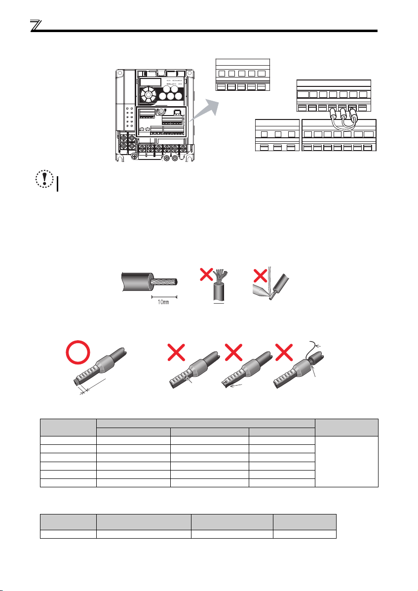
2.3.6 Wiring of control circuit
(1) Control circuit terminal layout
Recommend wire size:
2
0.3mm
to 0.75mm
NOTE
Do not remove the shortening wires across the terminals S1 and SC and the terminals S2 and SC.
Removing either shortening wire disables the inverter operation.
(2) Wiring method
Wiring
Use a blade terminal and a wire with a sheath stripped off for the control circuit wiring. For a single wire, strip off the sheath of
the wire and apply directly. Insert the blade terminal or the single wire into a socket of the terminal.
1) Strip off the sheath about the length below. If the length of the sheath peeled is too long, a short circuit may occur
among neighboring wires. If the length is too short, wires might come off.
Wire the stripped wire after twisting it to prevent it from becoming loose. In addition, do not solder it.
2
Wire stripping length
2) Crimp the blade terminal.
Insert wires to a blade terminal, and check that the wires come out for about 0 to 0.5 mm from a sleeve.
Check the condition of the blade terminal after crimping. Do not use a blade terminal of which the crimping is
inappropriate, or the face is damaged.
Blade terminals available on the market: (as of January 2017)
Phoenix Contact Co., Ltd.
Wire Size (mm2)
0.3 AI 0,34-10TQ — —
0.5 AI 0,5-10WH — AI 0,5-10WH-GB
0.75 AI 0,75-10GY A 0,75-10 AI 0,75-10GY-GB
1 AI 1-10RD A1-10 AI 1-10RD /1000GB
1.25, 1.5 AI 1,5-10BK A1,5-10 AI 1,5-10BK/1000GB
0.75 (for two wires) AI-TWIN 2 x 0,75-10GY — —
A ferrule terminal with an insulation sleeve compatible with MTW wire which has a thick wire insulation
Applicable for terminal ABC.
NICHIFU Co., Ltd.
Wire Size (mm2)
0.3 to 0.75 BT 0.75-11 VC 0.75 NH 69
With Insulation Sleeve Without In sulation Sleeve For UL Wire
Blade Terminal Product
Number
16
Ferrule Terminal Model
Insulation Cap Product
Number
Crimping Tool
Product Number
Crimping Tool
Name
CRIMPFOX 6
Page 21

Wiring
2
r
r
NOTE
Pulling out the terminal block forcefully without pushing
the open/close button all the way down may damage the
terminal block.
Use a small flathead screwdriver (Tip thickness: 0.4mm/
tip width: 2.5mm).
If a flathead screwdriver with a narrow tip is used,
terminal block may be damaged.
Products available on the market: (as of February 2016)
Place the flathead screwdriver vertical to the open/close
button. In case the blade tip slips, it may cause to damage of inverter or injury.
Product Typ e Manufacturer
Flathead
screwdriver
SZF 0- 0,4 x 2,5 Phoenix Contact Co., Ltd.
3) Insert the wire into a socket.
When using a single wire or a stranded wire without a blade terminal, push an
open/close button all the way down with a flathead screw driver, and insert the wire.
Open/close button
Flathead screwdrive
NOTE
When using a stranded wire without a blade terminal, twist enough to avoid short circuit with a nearby terminals or
wires.
Place the flathead screwdriver vertical to the open/close button. In case the blade tip slips, it may cause to damage of
inverter or injury.
Wire removal
Pull the wire with pushing the open/close button all the
way down firmly with a flathead screwdriver.
Open/close button
Flathead screwdrive
(3) Control circuit common terminals (SD, 5, SE)
• Terminals SD, SE and 5 are common terminals for I/O signals. (All common terminals are isolated from each other.) Do not
earth them. Avoid connecting the terminals SD and 5 and the terminals SE and 5.
• Terminal SD is a common terminal for the contact input terminals (STF, STR, RH, RM, AU) and the pulse train output
terminal (FM). The open collector circuit is isolated from the internal control circuit by photocoupler.
• Terminal 5 is a common terminal for the frequency setting signals (terminals 2 or 4). It should be protected from external
noise using a shielded or twisted cable.
• Terminal SE is a common terminal for the open collector output terminal (RUN). The contact input circuit is isolated from the
internal control circuit by photocoupler.
17
Page 22

Wiring
(4) Wiring instructions
• It is recommended to use the cables of 0.3mm2 to 0.75mm2 gauge for connection to the control circuit terminals.
• The maximum wiring length should be 30m (200m for terminal FM).
• Do not short across terminals PC and SD. Inverter may be damaged.
• When using contact inputs, use two or more parallel micro-signal contacts or
twin contacts to prevent contact faults since the control circuit input signals are
micro-currents.
• To suppress EMI, use shielded or twisted cables for the control circuit
terminals and run them away from the main and power circuits (including the
200V relay sequence circuit). For the cables connected to the control circuit terminals, connect their shields to the common
terminal of the connected control circuit terminal. When connecting an external power supply to the terminal PC, however,
connect the shield of the power supply cable to the negative side of the external power supply. Do not directly earth
(ground) the shield to the enclosure, etc.
• Always apply a voltage to the fault output terminals (A, B, C) via a relay coil, lamp, etc.
• When using an external power supply for transistor output, note the following points to prevent a malfunction caused by
undesirable current.
Do not connect any terminal SD on the inverter and the 0V terminal of the external power supply (when the sink logic is
selected).
Do not connect terminal PC on the inverter and the +24V terminal of the external power supply (when the source logic is
selected).
Do not install an external power source in parallel with the internal 24VDC power source (connected to terminals PC and
SD) to use them together.
Refer to Chapter 2 of the Instruction Manual (Applied) for the detail.
Micro signal contacts Twin contacts
2.3.7 Assigning signals (output stop signal (MRS), reset signal (RES), etc.) to contact input terminals
POINT
Use Pr.178 to Pr.182 (input terminal function selection) to select and change the functions assigned to input
terminals.
To assign the output stop signal (MRS) to the terminal RH, for example, assign "24" to Pr.182 RH terminal
function selection. (Refer to page 5 to change a parameter setting value.)
Pr. Name
178
STF terminal function selection
179
STR terminal function selection
180
AU terminal function selection
181
RM terminal function selection
RH terminal function selection
182
NOTE
Changing the terminal assignment using Pr.178 to Pr.182 (input terminal function selection) may affect the other functions.
Set parameters after confirming the function of each terminal.
Initial
Val ue
0: Low-speed operation command (RL)
60
1: Middle-speed operation command (RM)
2: High-speed operation command (RH)
3: Second function selection (RT)
61
4: Terminal 4 input selection (AU)
5: JOG operation selection (JOG)
7: External thermal relay input (OH)
4
8: Fifteen speed selection (REX)
10: Inverter operation enable signal (X10)
(FR-HC2/FR-CV connection)
1
12: PU operation external interlock (X12)
14: PID control valid terminal (X14)
16: PU-External operation switchover (X16)
2
24: Output stop (MRS)
Range
25: Start self-holding selection (STOP)
60: Forward rotation (STF)
61: Reverse rotation (STR)
62: Inverter reset (RES)
64: PID forward/reverse action switchover
(X64)
65: PU-NET operation switchover (X65)
66: External-NET operation switchover
(X66)
67: Command source switchover (X67)
72: PID integral value reset (X72)
9999: No function
Assigned to STF terminal (Pr. 178) only
Assigned to STR terminal (Pr. 179) only
18
Page 23

2
MC
Inverter
MC
R
PR
P/+
S/L2
T/L3
R/L1
OFF
ON
OCR
Contact
Power supply
F
<Example 1>
MC
High-duty brake
resistor (FR-ABR)
T
*2
Thermal relay
(OCR) (*1)
Inverter
MC
R
PR
P/+
S/L2
T/L3
R/L1
OFF
ON
B
C
Power supply
F
<Example 2>
MC
High-duty brake
resistor (FR-ABR)
OCR
Contact
T
MC
*2
Thermal relay
(OCR) (*1)
1/L
1
5/L
3
2/T
1
6/T
3
To the inverter
terminal P/+
To a resistor
Connection of a dedicated external brake resistor (MRS type, MYS type, FR-ABR)
2.4 Connection of a dedicated external brake resistor (MRS type, MYS type, FR-ABR)
Install a dedicated brake resistor (MRS type, MYS type, FR-ABR) outside when the motor driven by the inverter is made to run
by the load, quick deceleration is required, etc. Connect a dedicated brake resistor (MRS type, MYS type, FR-ABR) to
terminals P/+ and PR. (For the locations of terminals P/+ and PR, refer to the terminal block layout (page 13).)
Set the parameters below. (
Connected Brake Resistor Pr. 30 Regenerative function selection Setting Pr. 70 Special regenerative brake duty Setting
MRS type, MYS type 0 (initial value) —
MYS type
(used at 100% torque/6%ED)
FR-ABR 1
It is recommended to configure a sequence, which shuts off power in the input side of the inverter by the external thermal
relay as shown below, to prevent overheat and burnout of the brake resistor (MRS type, MYS type) and high duty brake
resistor (FR-ABR) in case the regenerative brake transistor is damaged.
Refer to the table below for the type number of each capacity of thermal relay and the diagram below for the connection.
(Always install a thermal relay when using a brake resistor whose capacity is 11K or higher.)
When the power supply is 400V class, install a step-down transformer.
Power
Supply
Vol tag e
200V
Power
Supply
Vol tag e
200V
400V
Brake Resistor
MRS120W200 TH-T25-0.7A
MRS120W100 TH-T25-1.3A
MRS120W60 TH-T25-2.1A
MRS120W40 TH-T25-3.6A
MYS220W50
(two units in parallel)
High-duty
Brake Resistor
FR-ABR-0.4K TH-T25-0.7A
FR-ABR-0.75K TH-T25-1.3A
FR-ABR-2.2K TH-T25-2.1A
FR-ABR-3.7K TH-T25-3.6A
FR-ABR-5.5K TH-T25-5A
FR-ABR-7.5K TH-T25-6.6A
FR-ABR-11K TH-T25-11A
FR-ABR-15K TH-T25-11A
FR-ABR-H0.4K TH-T25-0.24A
FR-ABR-H0.75K TH-T25-0.35A
FR-ABR-H1.5K TH-T25-0.9A
FR-ABR-H2.2K TH-T25-1.3A
FR-ABR-H3.7K TH-T25-2.1A
FR-ABR-H5.5K TH-T25-2.5A
FR-ABR-H7.5K TH-T25-3.6A
FR-ABR-H11K TH-T25-6.6A
FR-ABR-H15K TH-T25-6.6A
NOTE
The brake resistor connected should only be the dedicated brake resistor.
Perform wiring and operation according to the Instruction Manual of each option unit.
Brake resistor cannot be used with the brake unit, high power factor converter, power supply regeneration converter, etc.
Do not use the brake resistor (MRS type or MYS type) with a lead wire extended.
Do not connect a resistor directly to terminals P/+ and N/-. This could cause a fire.
Refer to the Instruction Manual (Applied) for the parameter details.)
16%
Thermal Relay Type
(Mitsubishi Electric
product)
TH-T25-5A
Thermal Relay Type
(Mitsubishi Electric
product)
Rated Operating Current
120VAC: 2A (NO contact) /
3A (NC contact),
240VAC: 1A (NO contact) /
2A (NC contact) (AC15 class)
110VDC: 0.2A,
220VDC: 0.1A (DC13 class)
Rated Operating Current
120VAC: 2A (NO contact) /
3A (NC contact),
240VAC: 1A (NO contact) /
2A (NC contact) (AC15 class)
110VDC: 0.2A,
220VDC: 0.1A (DC13 class)
7.5K or lower 10%
11K or higher 6%
19
Page 24

PRECAUTIONS FOR USE OF THE INVERTER
3 PRECAUTIONS FOR USE OF THE INVERTER
The FR-F700PJ series is a highly reliable product, but using incorrect peripheral circuits or incorrect operation/handling
methods may shorten the product life or damage the product.
Before starting operation, always recheck the following items.
(1) Use crimp terminals with insulation sleeve to wire the power supply and motor.
(2) Application of power to the output terminals (U, V, W) of the inverter will damage the inverter. Never perform
such wiring.
(3) After wiring, wire offcuts must not be left in the inverter (Filterpack).
Wire offcuts can cause an alarm, failure or malfunction. Always keep the inverter (Filterpack) clean.
When drilling mounting holes in an enclosure etc., take care not to allow chips and other foreign matter to enter the
inverter (Filterpack).
(4) Use cables of the appropriate size to make a voltage drop of 2% or less.
If the wiring distance is long between the inverter and motor, a main circuit cable voltage drop will cause the motor torque
to decrease especially at the output of a low frequency. Refer to page 22 for the recommended wire sizes.
(5) The total wiring length should be within the prescribed length.
Especially for long distance wiring, the fast-response current limit function may decrease, or the equipment connected to
the output side may malfunction. This is caused by a charging current due to the stray capacity of the wiring. Therefore,
note the overall wiring length. (Refer to page 24.)
(6) Electromagnetic wave interference
The input/output (main circuit) of the inverter includes high frequency components, which may interfere with the
communication devices (such as AM radios) used near the inverter. For an inverter without Filterpack, install the FR-BIF
optional capacitor type filter (for use in the input side only), FR-BSF01 or FR-BLF line noise filter to minimize
interference.
(7) Electrical corrosion of the bearing
When a motor is driven by the inverter, axial voltage is generated on the motor shaft, which may cause electrical
corrosion of the bearing in rare cases depending on the wiring, load, operating conditions of the motor or specific inverter
settings (high carrier frequency, use of a capacitive filter).
The following shows examples of countermeasures for the inverter.
Decrease the carrier frequency.
Remove the capacitive filter.
Provide a common mode choke on the output side of the inverter. (This is effective regardless of the use of the
capacitive filter.)
Mitsubishi Electric capacitive filter: FR-BIF, SF[], FR-E5NF-[], FR-S5NFSA[], FR-BFP2-[]
Recommended common mode choke: FT-3KM F series FINEMETR
FINEMET is a registered trademark of Hitachi Metals, Ltd.
(8) Do not install a power factor correction capacitor, surge suppressor or capacitor type filter on the inverter
output side.
This will cause the inverter to trip or the capacitor and surge suppressor to be damaged. If any of the above devices are
connected, immediately remove them.
(9) For some short time after the power is switched OFF, a high voltage remains in the smoothing capacitor.
When accessing the inverter for inspection, wait for at least 10 minutes after the power supply has been switched OFF,
and then make sure that the voltage across the main circuit terminals P/+ and N/- of the inverter is no more than 30VDC
using a tester, etc.
(10) A short circuit or earth (ground) fault on the inverter output side may damage the inverter modules.
Fully check the insulation resistance of the circuit prior to inverter operation since repeated short circuits may damage
the inverter modules. These short circuits may be caused by peripheral circuit inadequacy, an earth (ground) fault
caused by wiring inadequacy, or reduced motor insulation resistance.
Fully check the to-earth (ground) insulation and phase to phase insulation of the inverter output side before power-on.
Especially for an old motor or use in a hostile atmosphere, securely check the motor insulation resistance etc.
®
common mode choke cores manufactured by Hitachi Metals, Ltd.
20
Page 25

PRECAUTIONS FOR USE OF THE INVERTER
3
(11) Do not use the inverter input side magnetic contactor to start/stop the inverter.
Since repeated inrush currents at power ON will shorten the life of the converter circuit (switching life is about 1,000,000
times.) frequent starts and stops of the MC must be avoided. Turn ON/OFF the inverter start controlling terminals (STF,
STR) to run/stop the inverter.
(12) Across terminals P/+ and PR, connect only an external brake resistor.
Do not connect a mechanical brake.
(13) Do not apply a voltage higher than the permissible voltage to the inverter I/O signal circuits.
Application of a voltage higher than the permissible voltage to the inverter I/O signal circuits or opposite polarity may
damage the I/O devices. Especially check the wiring to prevent the speed setting potentiometer from being connected
incorrectly to short terminals 10 and 5.
(14) To use the commercial power supply, be sure to provide
electrical and mechanical interlocks between the electronic
bypass contactors MC1 and MC2.
When using a switching circuit as shown right, chattering due to
misconfigured sequence or arc generated at switching may
allow undesirable current to flow in and damage the inverter.
Miswiring may also damage the inverter.
(15) If the machine must not be restarted when power is restored after a power failure, provide a magnetic contactor
in the inverter's input side and also make up a sequence which will not switch ON the start signal.
If the start signal (start switch) remains ON after a power failure, the inverter will automatically restart as soon as the
power is restored.
(16) Inverter input side magnetic contactor (MC)
On the inverter input side, connect a MC for the following purposes. (Refer to page 7 for selection.)
1)To release the inverter from the power supply when a fault occurs or when the drive is not functioning (e.g. emergency
stop operation). For example, MC avoids overheat or burnout of the brake resistor when heat capacity of the resistor is
insufficient or brake regenerative transistor is damaged with short while connecting an optional brake resistor.
2)To prevent any accident due to an automatic restart at restoration of power after an inverter stop made by a power
failure
3)To separate the inverter from the power supply to ensure safe maintenance and inspection work.
If using an MC for emergency stop during operation, select an MC regarding the inverter input side current as JEM1038AC-3 class rated current.
(17) Handling of inverter output side magnetic contactor
Switch the magnetic contactor between the inverter and motor only when both the inverter and motor are at a stop. When
the magnetic contactor is turned ON while the inverter is operating, overcurrent protection of the inverter and such will
activate. If an MC is provided to switch to the commercial power supply or for similar purposes under general-purpose
motor control, switch the MC after the inverter and motor have stopped.
(18) Countermeasures against inverter-generated EMI
If electromagnetic noise generated from the inverter causes frequency setting signal to fluctuate and motor rotation
speed to be unstable when changing motor speed with analog signal, the following countermeasures are effective.
Do not run the signal cables and power cables (inverter I/O cables) in parallel with each other and do not bundle them.
Run signal cables as far away as possible from power cables (inverter I/O cables).
Use shield cables as signal cables.
Install a ferrite core on the signal cable (Example: ZCAT3035-1330 TDK).
(19) Instructions for overload operation
When performing operation of frequent start/stop of the inverter, rise/fall in the temperature of the transistor element of
the inverter will repeat due to a repeated flow of large current, shortening the life from thermal fatigue. Since thermal
fatigue is related to the amount of current, the life can be increased by reducing current at locked condition, starting
current, etc. Decreasing current may increase the life. However, decreasing current will result in insufficient torque and
the inverter may not start. A counter action for this is to raise the permissible current level by increasing the inverter
capacity (up to 2 ranks) when using a general-purpose motor, and by increasing the inverter and IPM motor capacities
when using an IPM motor.
(20) Make sure that the specifications and rating match the system requirements.
Power
supply
R/L1
S/L2
T/L3
Inverter
U
V
W
MC1
Interlock
IM
MC2
Undesirable current
21
Page 26

4 FAILSAFE OF THE SYSTEM WHICH USES THE INVERTER
When a fault occurs, the inverter trips to output a fault signal. However, a fault output signal may not be output at an inverter
fault occurrence when the detection circuit or output circuit fails, etc. Although Mitsubishi Electric assures best quality
products, provide an interlock which uses inverter status output signals to prevent accidents such as damage to machine
when the inverter fails for some reason and at the same time consider the system configuration where failsafe from outside
the inverter, without using the inverter, is enabled even if the inverter fails.
(1) Interlock method which uses the inverter status output signals
By combining the inverter status output signals to provide an interlock as shown below, an inverter alarm can be
detected.
No. Interlock Method Check Method Used Signals Refer to Page
Inverter protective function
1)
operation
2) Inverter operating status Operation ready signal check Operation ready (RY) signal
3) Inverter running status
4) Inverter running status
Operation check of an alarm contact
Circuit error detection by negative logic
Logic check of the start signal and
running signal
Logic check of the start signal and output
current
Fault (ALM) signal
Start (STF/STR) signal
Inverter running (RUN) signal
Start (STF/STR) signal
Output current detection (Y12)
signal
(2) Backup method outside the inverter
Even if the interlock is provided by the inverter status signal, enough failsafe is not ensured depending on the failure
status of the inverter itself. For example, when the inverter CPU fails, even if the interlock is provided using the inverter
fault signal, start signal and RUN signal, there is a case where a fault signal is not output and RUN signal is kept output
even if an inverter fault occurs.
Provide a speed detector to detect the motor speed and current detector to detect the motor current and consider the
backup system such as checking up as below according to the level of importance of the system.
1)Start signal and actual operation check
Check the motor running and motor current while the start signal is input to the inverter by comparing the start signal to
the inverter and detected speed of the speed detector or detected current of the current detector. Note that the motor
current runs as the motor is running for the period until the motor stops since the inverter starts decelerating even if the
start signal turns OFF. For the logic check, configure a sequence considering the inverter deceleration time. In addition, it
is recommended to check the three-phase current when using the current detector.
2)Command speed and actual operation check
Check if there is no gap between the actual speed and commanded speed by comparing the inverter speed command
and detected speed of the speed detector.
Controller
System failure
Refer to Chapter 4
of the Instruction
Manual (Applied).
Refer to Chapter 4
of the Instruction
Manual (Applied).
Refer to Chapter 4
of the Instruction
Manual (Applied).
Refer to Chapter 4
of the Instruction
Manual (Applied).
22
Inverter
Sensor
(speed, temperature,
air volume, etc.)
To the alarm detection sensor
Page 27

Setting procedure of IPM motor control
5
IPMIPMIPM
4
5 DRIVING THE IPM MOTOR
Highly efficient motor control and highly accurate motor speed control can be performed by using the inverter with an IPM motor.
The motor speed is detected by the output voltage and current of the inverter. It does not require a speed detector such as an
encoder. The inverter drives the IPM motor with the least required current when a load is applied in order to achieve the
highest motor efficiency.
Refer to Chapter 4 of the Instructio n Manual (Applied) for the details of the IPM motor control.
POINT
The following conditions must be met to perform IPM motor control.
For the motor model, dedicated IPM motor (MM-EF (1800r/min specification)) must be used.
The motor capacity must be equivalent to the inverter capacity.
Single-motor operation (one motor run by one inverter) must be performed.
The overall wiring length with the motor must be 100m or less (50m or less for the 400V class 0.4K).
5.1 Setting procedure of IPM motor control
This inverter is set for a general-purpose motor in the initial setting. Follow the following procedure to change the setting for
the IPM motor control.
Perform IPM parameter initialization by selecting the parameter setting mode (IPM) on the operation panel.* (Refer to page 24.)
Set "1" or "12" in " " (IPM parameter initialization)
to select IPM motor control. Refer to pa ge 24 for the setting
method.
Setting value "1": MM-EF
Setting value "12": MM-EFS
Set parameters such as the acceleration/deceleration time and multi-speed setting.
Set parameters such as the acceleration /deceleration time
and multi-speed setting as required.
Set the operation command. ( Refer to Chap ter 4 of the Instruction Manual (Applied).)
Tes t run
Initialization is performed by setting Pr.998 IPM parameter initialization or by choosing the mode on the operation panel.
To change to the IPM motor control, perform IPM parameter initialization at first. If parameter initialization is performed after setting other parameters, some
of those parameters will be initialized too. ( Refer to Chapter 4 of the Instruction Manual (Applied) for the parameters that are initialized.)
REMARKS
IPM motor control can also be selected with Pr. 80 Motor capacity and Pr. 998 IPM parameter initialization . ( Refer to
Chapter 4 of the Instruction Manual (Applied).)
To check the control method (general-purpose motor control/IPM motor control), simply press the setting dial while the monitor
screen is displayed. (
Refer to Chapter 4 of the Instruction Manual (Applied).)
NOTE
The selectable carrier frequencies under IPM motor control are 2.5kHz, 5kHz, 7.5kHz, 10kHz and 12.5kHz.
Constant-speed operation cannot be performed in the low-speed range of less than 150r/min (for the 1500r/min
specification MM-EFS) or 180r/min (for the 1800r/min specification MM-EFS). Generally, speed control can be
performed in the range that satisfies the ratio, 1:10.
During IPM motor control, the RUN signal is output about 100ms after turning ON the start command (STF, STR). The
delay is due to the magnetic pole detection.
The following operations and controls are disabled during IPM motor control: stop by power failure, Optimum
excitation control, and speed smoothing control.
The option surge voltage suppression filter (FR-ASF-H/FR-BMF-H) cannot be used under IPM motor control, so do
not connect them.
When parameter copy is performed from a FR-F700PJ series inverter, which is set to use MM-EFS under IPM motor
control, check that IPM motor control is selected on the operation panel after the copy. When parameters are copied
to a FR-F700PJ series inverter, which is not compatible with MM-EFS, General-purpose magnetic flux vector control
is selected instead of IPM moto r control.
Select the start command and speed command.
23
Page 28

Setting procedure of IPM motor control
The parameter
number read
previously appears.
(1) IPM motor control setting by selecting the parameter setting mode on the operation panel (" ")
POINT
The parameters required to drive an IPM motor are automatically changed as a batch. ( Refer to the
Instruction Manual (Applied).)
Operation example
Initialize the setting of some parameters for the premium high-efficiency IPM motor (MM-EFS) control by changing
the setting of Pr. IPM.
Operation Display
Screen at power-ON
1.
The monitor display appears.
2. Parameter setting mode
Press to choose the parameter setting
mode.
3. Selecting the parameter
Turn until " " (IPM parameter
initialization) appears.
4. Displaying the setting
Press to read the curr ently set value.
" " (initial value) appears.
5. Selecting the setting
Turn to change it to the set v alue " ".
6. Parameter setting
Press to set.
Alternate display.....Parameter setting complete.
Turn to read anot her parameter.
Press to show the setting again.
24
Press twice to show the automatic parameter setting (AUTO).
Setting Description
0
Parameter settings for a general-purpose motor
1
Parameter settings for a high-efficiency IPM motor MM-EF (rotations per minute)
12 Parameter settings for a premium high-efficiency IPM motor MM-EFS (rotations per minute)
REMARKS
Performing IPM parameter initialization in the parameter setting mode on the operation panel automatically changes the
Pr.998 IPM parameter initialization setting.
To check the control method (general-purpose motor control/IPM motor control), simply press the setting dial while the
monitor screen is displayed. ( Refer to Chapter 4 of the Instruction Manual (Applied).)
The IPM parameter setting is displayed as "1, 12" in the parameter setting mode even if Pr.998 IPM parameter
initialization ="101, 112".
Page 29

Start/stop from the operation panel (PU operation)
6
REMARKS
Set the required parameters according to the load and operating
conditions. (Refer to page 34.)
ON
Frequency
Time (s)
(Hz)
Start command
Frequency command
Output
frequency
Operation panel
6 DRIVING THE MOTOR
The inverter needs frequency command and start command.
Frequency command (set frequency) determines the rotation speed of the motor.
Turning ON the start command starts the motor to rotate.
6.1 Start/stop from the operation panel (PU operation)
POINT
From where is the frequency command given?
Operation at the frequency set in the frequency setting mode of the operation panel
Operation using the setting dial as the potentiometer refer to 6.1.2 (Refer to page 26.)
Change of frequency with ON/OFF switches connected to terminals refer to 6.1.3 (Refer to page 27.)
Perform frequency setting using voltage input signal refer to 6.1.4 (Refer to page 28.)
Perform frequency setting using current input signal
refer to 6.1.4 (Refer to page 28.)
6.1.1 Setting the frequency by the operation panel
Operation example Operate at 30Hz.
Operation
Screen at power-ON
1.
The monitor display appears.
Operation mode change
2.
Press to choose the PU operation mode. PU indicator is lit.
Frequency setting
Turn to show the frequency " " (30.00Hz) you want to set. The frequency blinks for about 5s. While the value is
blinking, press to set the frequency. " " and " " appear alternately. After about 3s, the indication of the value
3.
goes back to " " (0.00Hz) (monitor display). (If is not pressed, the indication of the value goes back to " "
(0.00Hz) after about 5s of blinking. In that case, turn again, and set the frequency.)
Star t acceleration constant speed
Press to start operation.
4.
The frequency value on the display increases in Pr. 7 Acceleration time, and " " (30.00Hz) appears.
(To change the set frequency, perform the operation in above step 3. The previously set frequency is displayed at first.)
Deceleration stop
5.
Press to stop. The frequency value on the display decreases in Pr. 8 Deceleration time, and the motor stops rotating with
" " displayed.
refer to 6.1.1 (Refer to page 25.)
REMARKS
can also be used like a potentiometer to perform operation.
When you always operate in the PU operation mode at power-ON, set Pr.79 Operation mode selection = "1" to choose the PU
operation mode always.
( Refer to Chapter 4 of the Instruction Manual (Applied).)
25
Page 30

Start/stop from the operation panel (PU operation)
6.1.2 Using the setting dial like a potentiometer to perform operation
POINT
Set "0" (extended parameter valid) in Pr. 160 User group read selection.
Set "1" (setting dial potentiometer mode) in Pr. 161 Frequency setting/key lock operation selection.
Operation example Change the frequency from 0Hz to 60Hz during operation
Operation
Screen at power-ON
1.
The monitor display appears.
Operation mode change
2.
Press to choose the PU operation mode. PU indicator is lit.
Selecting the setting dial mode
3.
Change the Pr. 160 setting to "0" and the Pr. 161 setting to "1".
(Refer to page 5 for change of the setting.)
Start
4.
Press to start the in verter.
Frequency setting
Turn until " " (60.00Hz) appears. The blinking frequency is the set frequency.
5.
You need not press .
REMARKS
If blinking "60.00" turns to "0.00", the Pr. 161 Frequency setting/key lock operation selection setting may not be "1".
Independently of whether the inverter is running or at a stop, the frequency can be set by merely turning the .
(Use Pr. 295 Magnitude of frequency change setting to change the frequency setting increments of .)
26
NOTE
When setting frequency by turning setting dial, the frequency goes up to the set value of Pr. 1 Maximum frequency
(initial value: 120Hz). Adjust Pr. 1 Maximum frequency setting according to the application.
Page 31

Start/stop from the operation panel (PU operation)
6
SD
RH
RM
RL
Inverter
Operation
panel
High speed
Middle speed
Low speed
6.1.3 Setting the frequency by switches (three-speed setting) (Pr. 4 to Pr. 6)
POINT
Use the operation panel ( ) to give a start command.
Switch ON the RH, RM, or RL signal to give a frequency command.
Set "4" (External/PU combined operation mode 2) in Pr. 79 Operation mode selection.
[Connection diagram]
Speed 1
(High speed)
Speed 2
(Middle speed)
Speed 3
(Low speed)
ON
Time
ON
ON
To input the RL signal, set "0" in any of Pr.178 to Pr.182 (Input terminal
function selection) to assign the function to the terminal.
Operation example Operation at low speed (10Hz)
Output frequency (Hz)
RH
RM
RL
Operation
Screen at power-ON
1.
The monitor display appears.
Easy operation mode setting
2.
Press and for 0.5s. " " appears, and the [PRM] indicator blinks.
Operation mode selection
3.
Turn until " " appears. [PU] and [PRM] indicators blink.
Operation mode setting
4.
Press to enter the setting. (Set "4" in Pr.79.)
" " and " " appear alternately. [PU] and [EXT] indicators are lit.
Star t
5.
Turn ON the low-speed switch (RL).
Acceleration constant speed
Press to start running.
6.
The frequency value on the display increases in Pr. 7 Acceleration time, and " " (10.00Hz) appears.
[RUN] indicator is lit during forward rotation operation and blinks slowly during reverse rotation operation.
Deceleration
Press to stop.
7.
The frequency value on the display decreases in Pr. 8 Deceleration time, and the motor stops rotating with " " (0.00Hz)
displayed.
Stop
8.
Turn OFF the low-speed switch (RL).
REMARKS
The initial settings of the RH, RM, and RL signals are 60Hz, 30Hz, and 10Hz. (Use Pr. 4, Pr. 5 and Pr. 6 to change.)
In the initial setting, when two or three of multi-speed settings are simultaneously selected, priority is given to the set frequency
of the lower signal.
For example, when the RH and RM signals turn ON, the RM signal (Pr. 5) has a higher priority.
27
Maximum of 15-speed operation can be performed. ( Refer to Chapter 4 of the Instruction Manual (Applied ).)
Page 32

Start/stop from the operation panel (PU operation)
5
10
2
Frequency
setting
potentiometer
Inverter
Operation
panel
5(-)
4(+)
Current signal
source
(4 to 20mADC)
SD
AU
AU signal
Inverter
Operation
panel
6.1.4 Setting the frequency by analog input (voltage input/current input)
POINT
Use the operation panel ( ) to give a start command.
Use the potentiometer (frequency setting potentiometer) (voltage input) or 4-to-20mA input (current input) to
give a frequency command.
Set "4" (External/PU combined operation mode 2) in Pr. 79 Operation mode selection.
[Connection example for voltage input] [Connection example for current input]
(The inverter supplies 5V power to the frequency setting
potentiometer. (terminal 10))
Operation example Operate at 60Hz.
Assign the AU signal in one of Pr. 178 to Pr. 182.
Operation
Screen at power-ON
1.
The monitor display appears.
Assignment of the AU signal (current input) (Refer to the step 3 for voltage input.)
Set Pr. 160 to "0" to activate extended parameters.
2.
To assign the AU signal, set "4" in one of Pr. 178 to Pr. 182. (Refer to page 5 to change the setting.)
Turn ON the AU signal.
Easy operation mode setting
3.
Press and for 0.5s. " " appears, and the [PRM] indicator blinks.
Operation mode selection
4.
Turn until " " appears. [PU] and [PRM] indicators blink.
Operation mode setting
5.
Press to enter the setting. (Set "4" in Pr.79.)
" " and " " appear alternately. [PU] and [EXT] indicators are lit.
Start
6.
Press . [RUN] blinks fast as no frequency command is given.
Acceleration constant speed
For voltage input, turn the potentiometer (frequency setting potentiometer) clockwise slowly to full.
For current input, input 20mA.
7.
The frequency value on the display increases in Pr. 7 Acceleration time, and " " (60.00Hz) appears.
[RUN] indicator is lit during forward rotation operation and blinks slowly during reverse rotation operation.
Deceleration
For voltage input, turn the potentiometer (frequency setting potentiometer) counterclockwise slowly to full.
For current input, input 4mA.
8.
The frequency value on the display decreases in
[RUN] blinks fast.
Stop
9.
Press . [RUN] indicator turns OFF.
Pr. 8 Deceleration time,
and the motor stops rotating with " " (0.00Hz) displayed.
28
REMARKS
For voltage input, the frequency (maximum potentiometer setting) at the full right turn of the (frequency setting) potentiometer is
60Hz in the initial setting. (To change the setting, use Pr.125.) (Refer to page 32.)
To input 10VDC to terminal 2, set Pr. 73 Analog input selection = "0". The initial value is "1 (0 to 5V input)". ( Refer to Chapter
4 of the Instruction Manual (Applied).)
For current input, the frequency at 20mA input is 60Hz in the initial setting. (To change the setting, use Pr. 126.) (Refer to
Chapter 4 of the Instruction Manual (Applied).)
Page 33

6
6.2 Start and stop using terminals (External operation)
SD
STF
STR
Inverter
Operation
panel
Forward rotation start
Reverse rotation start
[Connection diagram]
6.2.1 Setting the frequency by the operation panel (Pr. 79 = 3)
Operation example Operate at 30Hz.
1.
2.
3.
4.
5.
6.
7.
Start and stop using terminals (External operation)
POINT
From where is the frequency command given?
Operation at the frequency set in the frequency setting mode of the operation panel refer to 6.2.1
Give a frequency command by switch (multi-speed setting) refer to 6.2.2 (Refer to page 30.)
Perform frequency setting by a voltage input signal refer to 6.2.3 (Refer to page 31.)
Perform frequency setting by a current input signal refer to 6.2.3 (Refer to page 31.)
(Refer to page 29.)
POINT
Switch ON the STF (STR) signal to give a start command.
Use the operation panel ( ) to give a frequency command.
Set "3" (External/PU combined operation mode 1) in Pr. 79.
Operation
Screen at power-ON
The monitor display appears.
Easy operation mode setting
Press and for 0.5s. " " appears, and the [PRM] indicator blinks.
Operation mode selection
Turn until " " appears. [EXT] and [PRM] indicators blink.
Operation mode setting
Press to enter the setting. (Set "3" in Pr.79.)
" " and " " appear alternately. [PU] and [EXT] indicators are lit.
Frequency setting
Turn to show the frequency " " you want to set. The frequency blinks for about 5s. While the value is blinking,
press to set the frequency. " " and " " appear alternately. After about 3s of blinking, the indication of the value
goes back to " " (monitor disp lay). (If is not pressed, the indicatio n of the value goes back to " " ( 0.00Hz)
after about 5s of blinking. In that case, turn again, and set the frequency.)
Star t acceleration constant speed
Turn the start switch (STF or STR) ON.
The frequency value on the display increases in Pr. 7 Acceleration time, and " " (30.00Hz) appears.
[RUN] indicator is lit during forward rotation operation and blinks during reverse rotation operation.
(To change the set frequency, perform the operation in above step 5. The previously set frequency is displayed at first.)
Deceleration stop
Turn OFF the start switch (STF or STR). The frequency value on the display decreases in Pr. 8 Deceleration time, and the motor
stops rotating with " " (0.00Hz) displayed.
[RUN] turns OFF.
29
Page 34

Start and stop using terminals (External operation)
Inverter
Forward rotation start
Reverse rotation start
High speed
RM
STF
STR
RH
Middle speed
Low speed
SD
RL
[Connection diagram]
ON
ON
ON
Output frequency (Hz)
Speed 1
(High speed)
Speed 2
(Middle speed)
Speed 3
(Low speed)
RH
RM
RL
Time
6.2.2 Setting the frequency by switches (three-speed setting) (Pr. 4 to Pr. 6)
POINT
Switch ON the STF (STR) signal to give a start command.
Switch ON the RH, RM, or RL signal to give a frequency command.
To input the RL signal, set "0" in any of Pr.178 to Pr.182 (Input terminal
function selection) to assign the function to the terminal.
Operation example Operation at high speed (60Hz)
Operation
Screen at power-ON
1.
The monitor display appears.
Start
2.
Turn ON the high-speed switch (RH).
Acceleration constant speed
Turn ON the start switch (STF or STR). The frequency value on the display increase s in Pr. 7 Acceleration time, and " "
3.
(60.00Hz) appears.
[RUN] indicator is lit during forward rotation operation and blinks during reverse rotation operation.
When RM is turne d ON, 30Hz is displayed. When RL is turned ON, 10Hz is displayed.
Deceleration
Turn OFF the start switch (STF or STR). The frequency value on the display decreases in Pr. 8 Deceleration time, and the motor
4.
stops rotating with " " (0.00Hz) displayed.
[RUN] turns OFF.
Stop
5.
Turn OFF the high-speed switch (RH)
30
REMARKS
To always select the External operation mode, set Pr.79 Operation mode selection = "2 (External operation mode)".
Initial settings of RH, RM and RL signals are 60Hz, 30Hz, and 10Hz. (To change, set Pr. 4, Pr. 5 and Pr. 6.)
In the initial setting, when two or three of m ulti-speed settings are simultaneously selected, priority is given to the set frequency
of the lower signal.
For example, when the RH and RM signals turn ON, the RM signal (Pr. 5) has a higher priority.
Maximum of 15-speed operation can be performed. ( Refer to Chapter 4 of the In struction Manual (Applied).)
Page 35

Start and stop using terminals (External operation)
6
6.2.3 Setting the frequency by analog input (voltage input/current input)
POINT
Switch ON the STF (STR) signal to give a start command.
Use the potentiometer (frequency setting potentiometer) (voltage input) or 4-to-20mA input (current input) to
give a frequency command.
[Connection example for voltage input] [Connection example for current input]
(The inverter supplies 5V power to the frequency setting
potentiometer. (terminal 10))
Forward rotation start
Reverse rotation start
Frequency setting
potentiometer
Operation example Operate at 60Hz.
STF
STR
SD
10
2
5
Inverter
Assign the AU signal in one of Pr. 178 to Pr. 182.
Forward rotation start
Reverse rotation start
AU signal
Current signal
source
(4 to 20mADC)
STF
STR
AU signal (terminal RH)
SD
4(+)
5(-)
Inverter
Operation
Screen at power-ON
1.
The monitor display appears.
Assignment of the AU signal (current input) (Refer to the step 3 for voltage input.)
Set Pr. 160 to "0" to activate extended parameters.
2.
To assign the AU signal, set "4" in one of Pr. 178 to Pr. 182. (Refer to page 5 to change the setting.)
Turn ON the AU signal.
Star t
3.
Turn the start switch (STF or STR) ON.
[RUN] blinks fast because the frequency command is not given.
Acceleration constant speed
For voltage input, turn the potentiometer (frequency setting potentiometer) clockwise slowly to full.
For current input, input 20mA.
4.
The frequency value on the display increases in Pr. 7 Acceleration time, and " " (60.00Hz) appears.
[RUN] indicator is lit during forward rotation operation and blinks slowly during reverse rotation operation.
Deceleration
For voltage input, turn the potentiometer (frequency setting potentiometer) counterclockwise slowly to full.
For current input, input 4mA.
5.
The frequency value on the displa y decreases in
[RUN] blinks fast.
Stop
6.
Turn the start switch (STF or STR) OFF.
[RUN] turns OFF.
REMARKS
For voltage input, the frequency (maximum potentiometer setting) at the full right turn of the (frequency setting) potentiometer is
60Hz in the initial setting. (To change the setting, use Pr.125.) (Refer to page 32.)
To input 10VDC to the terminal 2, set Pr. 73 Analog inp ut selection = "0". The initial value is "1 (0 to 5V input)". ( Refer to
Chapter 4 of the Instruction Manua l (Applied).)
For current input, the frequency at 20mA input is 60Hz in the initial setting. (To change the setting, use Pr. 126.) ( Refer to
Chapter 4 of the Instruction Manua l (Applied).)
To always select the External operation mode, set Pr. 79 Operation mode selection = "2 (External operation mode)".
Pr. 8 Deceleration time,
and the motor stops rotat ing with " " (0.00H z) displayed.
31
Page 36

Start and stop using terminals (External operation)
6.2.4 Operating at 60Hz or higher using the external potentiometer
< How to change the maximum frequency>
Changing
example
When you want to use 0 to 5VDC input frequency setting potentiometer to change the frequency at 5V from 60Hz (initial value)
to 70Hz, make adjustment to output "70Hz" at 5V voltage input . Set "70Hz" in Pr. 125.
Operation
Parameter selection
Turn until " " (Pr. 125) appears.
1.
Press to show the present set value " " (60.00Hz).
Changing the maximum frequency
Turn to change the set value to " "(70.00Hz).
2.
Press to enter. " " and " " appear alternately.
Mode/monitor check
3.
Press
Start
4.
Turn the start switch (STF or STR) ON.
[RUN] blinks fast because the frequency command is not given .
Acceleration constant speed
Turn the potentiometer (frequency setting potentiometer) clockwise slowly to full.
5.
The frequency value on the display increases in Pr. 7 Acceleration time, and " " (70.00Hz) appears.
[RUN] indicator is lit during forward rotation operation and blinks slowly during reverse rotation operation.
Deceleration
Turn the potentiometer (frequency setting potentiometer) counterclockwise slowly to full.
6.
The frequency value on the
displayed
[RUN] blinks fast.
Stop
7.
Turn the start switch (STF or STR) OFF.
[RUN] turns OFF.
twice to choose the monitor/frequency monitor.
display
.
decreases in
Pr. 8 Deceleration time
, and
the motor stops rotating with " " (0.00Hz)
REMARKS
To change the value to 120Hz or more, the maximum frequency must be set to 120Hz or more.
Use calibration parameter C2 to set frequency at 0V and
calibration parameter C0 to adjust the meter.
(
Refer to Chapter 4 of the Instruction Ma nual (Applied).)
• To input 10VDC to the terminal 2, set Pr.73 Analog input
selection = "0". The initial value is "1 (0 t o 5V input)".
(
Refer to Chapter 4 of the Instruction Ma nual (Applied).)
As other adjustment methods of frequency setting voltage gain, there are methods to adjust with a voltage applied across
terminals 2 and 5 or a method to adjust at any point without a voltage applied. ( Refer to Chapter 4 of the Instruction Manual
(Applied) for the setting method of calibration parameter C4.)
Change the frequency (60Hz) at the maximum current input (20mA in the initial setting)
Adjust it with Pr.126 Terminal 4 frequency setting gain frequency. ( Refer to Chapter 4 of the Instr uction Manual (Applied).)
Change the frequency (0Hz) at the minimum current input (4mA in the initial setting)
Adjust with the calibration parameter C5 Terminal 4 frequency setting bias frequency. ( Refer to Chapter 4 of the Instruction
Manual (Applied).)
Output
frequency
Bias
C2 (Pr. 902)
60Hz
(Hz)
0
05V
0
C3 (Pr. 902) C4 (Pr. 903)
Initial value
Frequency
setting signal
Gain
Pr. 125
100%
10V
32
Page 37

ENERGY SAVING OPERATION FOR FANS AND PUMPS
7
100%
Output voltage
Pr. 3 Base frequency
Output frequency (Hz)
Pr. 14 = 1
7 ENERGY SAVING OPERATION FOR FANS AND
PUMPS
Set the following functions to perform energy saving operation for fans and pumps.
(1) Load pattern selection (Pr. 14)
Select the optimum output characteristic (V/F characteristic) that is suitable for the
application and load characteristics.
Set Pr.14 Load pattern selection = "1 (for variable-torque load)."
When the output frequency is equal to or less than the base frequency, the output voltage
changes by its square in proportion to the output frequency.
Use this setting to drive a load whose load torque changes in proportion to the square of
the speed, such as a fan and a pump.
NOTE
Load pattern selection is available only under V/F control. Load pattern selection is not available under IPM motor
control and General-purpose magnetic flux vector control. (
(2) Optimum excitation control (Pr. 60)
Without a detailed parameter setting, the inverter automatically performs energy saving operation.
This operation is optimum for fan and pump applications.
Set Pr.60 Energy saving control selection = "9 (optimum excitation control mode)."
The Optimum excitation control mode is a control system which controls excitation current to improve the motor efficiency
to the maximum and determines output voltage as an energy saving method.
REMARKS
When the motor capacity is too small as compared to the inv erter capacity or two or more motors are conne cted to one inverter,
the energy saving effect is not expected.
Refer to Chapter 4 of the Instruction Manual (Applied).)
NOTE
When the Optimum excitation control mode is selected, deceleration time may be longer than the setting value. Since
Optimum excitation control is available only under V/F control. Optimum excitation control is not available under IPM
Optimum excitation control will not be performed during an automatic restart after instantaneous power failure.
Since output voltage is controlled by Optimum excitation control, output current may slightly increase.
overvoltage alarm tends to occur as compared to the constant-torque load characteristics, set a longer deceleration
time.
motor control and General-purpose magnetic flux vector control. (
(Applied).)
Refer to Chapter 4 of the Instruction Manual
33
Page 38

Simple mode parameters
V/FV/FV/F
V/FV/FV/F
GP
MFVC
8 PARAMETERS
Simple variable-speed operation can be performed with the inverter in the initial settings. Set the required parameters
according to the load and operating conditions. Use the operation panel to set or change a parameter. (Refer to Chapter 4
of the Instruction Manual (Applied) for the detailed description of parameters.)
8.1 Simple mode parameters
POINT
In the initial setting, only the simple mode parameters are displayed by the Pr. 160 Extended function display selection
setting. Change the Pr. 160 Extended function display selection setting as required. (Refer to page 5 to change the
parameter.)
Parameter
Number
0
Torque boost 0.1%
1 Maximum frequency 0.01Hz 120Hz 0 to 120Hz
2 Minimum frequency 0.01Hz 0Hz 0 to 120Hz
3
Base frequency 0.01Hz 60Hz 0 to 400Hz
GP
MFVC
GP
MFVC
4 Multi-speed setting (high speed) 0.01Hz 60Hz 0 to 400Hz
Multi-speed setting (middle
5
speed)
6 Multi-speed setting (low speed) 0.01Hz 10Hz 0 to 400Hz
7 Acceleration time 0.1s 5s/15s 0 to 3600s Use these parameters to set the acceleration/deceleration
8 Deceleration time 0.1s 10s/30s 0 to 3600s
9 Elect ronic thermal O/L relay 0.01A
79 Operation mode selection 1 0
Terminal 2 frequency setting
125
gain frequency
Terminal 4 frequency setting
126
gain frequency
Extended function display
160
selection
998 IPM parameter initialization 1 0
Name Unit
Initial
Val ue
6%/4%/3%/
0.01Hz 30Hz 0 to 400Hz
Inverter
current
0.01Hz 60Hz 0 to 400Hz
0.01Hz 60Hz 0 to 400Hz
1 9999
Range Application
0 to 30%
2%
rated
0 to 500A
0 External/PU switchover mode
1 Fixed to PU operation mode
2 F ixed to External operation mo de
3
4
6 Switchover mode
7 External operation mode (PU operation interlock)
0 Simple mode + extended mode parameters are displayed.
9999 Only the simple mode parameters are displayed.
0, 1, 12,
101, 112
Use this parameter to increase starting torque under V/F
control. Use this when a loaded motor cannot be driven
and the warning [OL] occurs, then the inverter trips with
[OC1] under V/F control.
Initial value depends on the inverter capacity.
(0.75K or lower/1.5K to 3.7K/5.5K, 7.5K/11K, 15K)
Use this parameter to set the u pper limit for the output
frequency.
Use this parameter to set the lo wer limit for the output
frequency.
Use this parameter when the rated motor frequency is 50Hz.
Check the rating plate of the motor.
Use these parameters to change among pre-set operation
speeds with the terminals. The speeds are pre-set with
parameters.
time.
Initial value depends on the inverter capacity.
(7.5K or lower/11K, 15K)
With this parameter, the inverter protects the motor from
heat.
Set the rated motor current.
External/PU combined operation mode 1
(Start command from External, frequency command from
PU)
External/PU combined operation mode 2
(Frequency command from External, start command from
PU)
Use this parameter to change the frequency at the
maximum potentiometer setting (5V in the initial setting)
Use this parameter to change the frequency at the
maximum current input (20mA in the initial setting)
By performing IPM parameter initialization, IPM motor
control is selected and the parameters, which are required
to drive an IPM motor, are changed.
34
Page 39

Parameter list
8
Parameter
Number
999 Automatic parameter setting 1 9999
Pr.CL Parameter clear 1 0 0, 1
ALLC All parameter clear 1 0 0, 1 Setting "1" returns all parameters to the initial values .
Er.CL Fault history cle ar 1 0 0, 1 Setting "1" clears eight past faults.
Pr.CH Initial value change list
IPM IPM parameter initializ ation 1 0 0, 1, 12
AUTO Automatic parameter setting
Name Unit
Initial
Valu e
Range Application
Parameter settings are changed as a batch. Those
10, 20, 21,
9999
include communication parameter settings for the
Mitsubishi's human machine interface (GOT) connection
and the parameter setting for the rated frequency settings
of 50Hz/60Hz.
Setting "1" returns all parameters except calibration
parameters to the initial values.
Displays and sets the parameters changed from the initial
value.
Use this parameter to select the IPM motor control and to
change parameter settings to the settings required to
drive an IPM motor.
Parameter settings are changed as a batch.
Those include communication parameter settings for the
Mitsubishi's human machine interface (GOT) connection
and the parameter setting for the rated frequency settings
of 50Hz.
8.2 Parameter list
REMARKS
indicates simple mode parameters.
The parameters surrounded by a black border in the table allow its setting to be changed during operation even if "0" (initial
value) is set in Pr. 77 Parameter write selection.
Parameter
0 Torque boost 0 to 30%
1 Maximum frequency 0 to 120Hz 120Hz
2 Minimum frequency 0 to 120Hz 0Hz
3 Base frequency 0 to 400Hz 60Hz
Multi-speed setting (high
4
speed)
Multi-speed setting (middle
5
speed)
Multi-speed setting (low
6
speed)
7 Acceleration tim e 0 to 3600s 5/15s
8 Deceleration time 0 to 3600s 10/30s
9 Electronic th ermal O/L relay 0 to 500A
DC injection brake operation
10
frequency
DC injection brake operation
11
time
DC injection brake operation
12
voltage
13 Starting frequency 0 to 60Hz 0.5Hz
14 Load pattern selection 0, 1 1
15 Jog frequency 0 to 400Hz 5Hz
Jog acceleration/deceleration
16
time
17 MRS input selection 0, 2, 4 0
High speed maximum
18
frequency
19 Base frequen cy voltage
Acceleration/deceleration
20
reference frequency
22 Stall prevention operation le vel 0 to 150% 120%
Name
Setting
Range
0 to 400Hz 60Hz
0 to 400Hz 30Hz
0 to 400Hz 10Hz
0 to 120Hz 3Hz
0 to 10s 0.5s
0 to 30% 4/2%
0 to 3600s 0.5s
120 to 400Hz 1 20Hz
0 to 1000V,
8888, 9999
1 to 400Hz 60Hz
Initial
Valu e
6/4/3/2%
Inverter
rated
current
9999
Parameter
Stall prevention operation level
23
compensation factor at double
speed
24 Multi- speed setting (speed 4)
25 Multi- speed setting (speed 5)
26 Multi- speed setting (speed 6)
27 Multi- speed setting (speed 7)
Acceleration/deceleration
29
pattern selection
Regenerative function
30
selection
31 Frequency jump 1A
32 Frequency jump 1B
33 Frequency jump 2A
34 Frequency jump 2B
35 Frequency jump 3A
36 Frequency jump 3B
37 Speed display
RUN key rotation direction
40
selection
41 Up-to-frequency sensitivity 0 to 100% 10%
42 Outp ut frequency detection 0 to 400 Hz 6Hz
Output frequency detection for
43
reverse rotation
Second acceleration/
44
deceleration time
Name
Setting
Range
0 to 200%,
9999
0 to 400Hz,
9999
0 to 400Hz,
9999
0 to 400Hz,
9999
0 to 400Hz,
9999
0 to 2 0
0 to 2 0
0 to 400Hz,
9999
0 to 400Hz,
9999
0 to 400Hz,
9999
0 to 400Hz,
9999
0 to 400Hz,
9999
0 to 400Hz,
9999
0,
0.01 to 9998
0, 1 0
0 to 400Hz,
9999
0 to 3600s 5/15s
Initial
Val ue
9999
9999
9999
9999
9999
9999
9999
9999
9999
9999
9999
0
9999
35
Page 40

Parameter list
Parameter
45 Second deceleration time
46 Second torque boost
47 Second V/F (base frequency)
Second stall prevention
48
operation current
Second electronic thermal O/L
51
relay
DU/PU main display data
52
selection
54 FM termin al function selection
Frequency monitoring
55
reference
56 Current monitoring reference 0 to 500A
57 Restart coasting time
58 Restart cushio n time 0 to 60s 1s
59 Remote function selection 0 to 3 0
Energy saving control
60
selection
65 Retry select ion 0 to 5 0
Stall prevention operation
66
reduction starting frequency
Number of retries at fault
67
occurrence
68 Retry waiting time 0.1 to 600s 1s
69 Retry co unt display erase 0 0
Special regenerative brake
70
duty
71 Applied motor
72 PWM freq uency selection 0 to 15 1
73 Analog inpu t selection 0, 1, 10, 11 1
74 Input filt er time constant 0 to 8 1
Reset selection/disconnected
75
PU detection/PU stop
selection
77 Parameter write selection 0 to 2 0
Reverse rotation prevention
78
selection
79 Operation mode selection 0 to 4, 6, 7 0
80 Motor c apacity
82 Motor e xcitation current
83 Rated m otor voltage 0 to 1000V
84 Rated motor frequency 10 to 120Hz 60Hz
90 Motor c onstant (R1)
96 Auto tun ing setting/status 0, 11, 21 0
PU communication station
117
number
118 PU communication speed
PU communication stop bit
119
length
Name
Setting
Range
0 to 3600s,
9999
0 to 30%,
9999
0 to 400Hz,
9999
0 to 150%,
9999
0 to 500A,
9999
0, 5, 8 to 12,
14, 20,
23 to 25,
50 to 55, 61,
62, 64, 100
1 to 3, 5,
8 to 12, 14,
21, 24, 50,
52, 53, 61,
62
0 to 400Hz 60Hz
0, 0.1 to 5s,
9999
0, 9 0
0 to 400Hz 60Hz
0 to 10,
101 to 110
0 to 30% 0%
0, 1, 3, 13,
23, 40, 43,
50, 53, 120,
210
0 to 3,
14 to 17
0 to 2 0
0.4 to 15kW,
9999
0 to 500A,
9999
0 to 50,
9999
0 to 31
(0 to 247)
48, 96, 192,
384
0, 1, 10, 11 1
Initial
Val ue
9999
9999
9999
9999
9999
0
1
Inverter
rated
current
9999
0
0
14
9999
9999
200/400V
9999
0
192
Parameter
120
121
122
123
124
125
126
127
128 PID ac tion selection 0, 20, 21 0
129 PID pr oportional band
130 PID integ ral time
131 PID upp er limit
132 PID low er limit
133 PID ac tion set point
134 PID differential time
144 Speed setting switchover
145 PU display language selection 0 to 7 0
146
150 Outp ut current detection level 0 to 150% 120%
151
152 Zero current detection level 0 to 150% 5%
153 Zero current detection time 0 to 1s 0.5s
154
156
157 OL s ignal output timer
160
161
162
165
166
167
168
169
170 Watt-hour meter clear 0, 10, 9999 9999
171 Ope ration hour meter clear 0, 9999 9999
Name
PU communication parity
check
Number of PU communication
retries
PU communication check time
interval
PU communication waiting
time setting
PU communication CR/LF
selection
Terminal 2 frequency setting
gain frequency
Terminal 4 frequency setting
gain frequency
PID control automatic
switchover frequency
Built-in potentiometer
switching
Output current detection signal
delay time
Voltage reduction selection
during stall prevention
operation
Stall prevention operation
selection
Extended function display
selection
Frequency setting/key lock
operation selection
Automatic restart after
instantaneous power failure
selection
Stall prevention operation level
for restart
Output current detection signal
retention time
Output current detection
operation selection
Parameter for manufacturer setting . Do not set.
Setting
Range
0 to 2 2
0 to 10, 9999 1
0,
0.1 to 999.8s,
9999
0 to 150ms,
9999
0 to 2 1
0 to 400Hz 60Hz
0 to 400Hz 60Hz
0 to 400Hz,
9999
0.1 to 1000%,
9999
0.1 to 3600s,
9999
0 to 100%,
9999
0 to 100%,
9999
0 to 100%,
9999
0.01 to 10s,
9999
2, 4, 6, 8, 10,
102, 104,
106, 108,
110
0, 1 1
0 to 10s 0s
1, 11 1
0 to 31, 100,
101
0 to 25s,
9999
0, 9999 9999
0, 1, 10, 11 0
0, 1, 10, 11 1
0 to 150% 120%
0 to 10s,
9999
0, 1 0
Initial
Valu e
0
9999
9999
100%
1s
9999
9999
9999
9999
4
0
0s
0.1s
36
Page 41

Parameter list
8
Parameter
178 STF terminal function selection
STR terminal function
179
selection
180 AU te rminal function selection 4
181 RM terminal fu nction selection 1
182 RH te rminal function selection 2
RUN terminal function
190
selection
A,B,C terminal function
192
selection
232 Multi-speed setting (speed 8)
233 Multi-speed setting (speed 9)
234 Multi-speed setting (speed 10)
235 Multi-speed setting (speed 11)
236 Multi-speed setting (speed 12)
237 Multi-speed setting (speed 13)
238 Multi-speed setting (speed 14)
239 Multi-speed setting (speed 15)
240 Soft-PWM operation selection 0, 1 1
Analog input display unit
241
switchover
244 Cooling fan operation selection 0, 1 1
245 Rated slip
Slip compensation time
246
constant
Constant-power range slip
247
compensation selection
Earth (ground) fault detection
249
at start
250 Stop selection
Output phase loss protection
251
selection
255 Life alarm status display (0 to 15) 0
Inrush current limit circuit life
256
display
Control circuit capacitor life
257
display
Main circuit capacitor life
258
display
Main circuit capacitor life
259
measuring
PWM frequency automatic
260
switchover
261 Power failure stop selection 0 to 2 0
267 Terminal 4 input selection 0 to 2 0
Name
Setting
Range
0 to 5, 7, 8,
10, 12, 14,
16, 24, 25,
, 61
60
62, 64 to 67,
72, 9999
0, 1, 3, 4, 7, 8,
11 to 16, 25,
26, 46 to 48,
57, 64, 70, 79,
90, 91, 92
, 95, 96,
93
98 to 101, 103,
104, 107, 108,
111 t o 116,
125, 126,
146 to 148,
157, 164, 170,
179, 190, 191,
192
195, 196, 198,
199, 9999
0 to 400Hz,
9999
0 to 400Hz,
9999
0 to 400Hz,
9999
0 to 400Hz,
9999
0 to 400Hz,
9999
0 to 400Hz,
9999
0 to 400Hz,
9999
0 to 400Hz,
9999
0, 1 0
0 to 50%,
9999
0.01 to 10s 0.5s
0, 9999 9999
0, 1 0
0 to 100s,
1000 to
1100s,
8888, 9999
0, 1 1
(0 to 100%) 100%
(0 to 100%) 100%
(0 to 100%) 100%
0, 1
(2, 3, 8, 9)
0, 1 1
, 193 ,
Initial
Parameter
Valu e
60
61
0
,
99
9999
9999
9999
9999
9999
9999
9999
9999
9999
9999
0
Monitor decimal digits
268
selection
269 P arameter for manufacturer settin g. Do not set.
Magnitude of frequency
295
change setting
296 P assword lock level
297 Pas sword lock/unlock
298 Fr equency search gain
Rotation direction detection
299
selection at restarting
Communication operation
338
command source
Communication speed
339
command source
Communication startup mode
340
selection
Communication EEPROM
342
write selection
343 Communication error count — 0
374 Overspeed detection level
450 Second applied motor 0, 1, 9999 9999
495 Remote output selection 0, 1, 10, 11 0
496 Remote output data 1 0 to 4095 0
Stop mode selection at
502
communication error
503 Maintenance timer 0 (1 to 9998) 0
Maintenance timer alarm output
504
set time
505
Speed setting reference
549 Pro tocol selection 0, 1 0
PU mode operation command
551
source selection
553 PID de viation limit
554 PID signal operation selection
555 Current average time 0.1 to 1s 1s
556 D ata output mask time 0 to 20s 0s
Current average value monitor
557
signal output reference current
561 PTC thermistor protection level
Energization time carrying-
563
over times
Operating time carrying -over
564
times
571 Hold ing time at a start
Output interruption detection
575
time
Output interruption detection
576
level
Output interruption cancel
577
level
611 Acceleration time at a restart
653 Speed smoothin g control 0 to 200% 0%
Regeneration avoidance
665
frequency gain
Operation frequency during
779
communication error
Acceleration time in low-speed
791
range
Name
Setting
Range
0, 1, 9999 9999
0, 0.01, 0.10,
1.00, 10.00
1 to 6,
101 to 106,
9999
1000 to 9998
(0 to 5, 9999)
0 to 32767,
9999
0, 1, 9999 0
0, 1 0
0 to 2 0
0, 1, 10 0
0, 1 0
0 to 400Hz,
9999
0 to 3 0
0 to 9998,
9999
1 to 120Hz 60Hz
2, 4, 9999 9999
0 to 100.0%
9999
0 to 3, 10 to
13
0 to 500A
0.5 to 30k ,
9999
(0 to 65535) 0
(0 to 65535) 0
0 to 10s,
9999
0 to 3600s,
9999
0 to 400Hz 0Hz
900 to
1100%
0 to 3600s,
9999
0 to 200% 100%
0 to 400Hz,
9999
0 to 3600s,
9999
Initial
Val ue
0
9999
9999
9999
9999
9999
9999
0
Inverter
rated
current
9999
9999
1s
1000%
9999
9999
9999
37
Page 42

Parameter list
Parameter
Deceleration time in low-speed
792
range
Pulse increment setting for
799
output power
Name
Setting
Range
0 to 3600s,
9999
0.1kWh,
1kWh,
10kWh,
100kWh,
1000kWh
Control method selection
800
Speed control P gain 1
820
Speed control integral time 1
821
Speed detection hysteresis
870
Input phase loss protection
872
selection
Regeneration avoidance
882
operation selection
Regeneration avoidance
883
operation level
Regeneration avoidance
885
compensation frequency limit
value
Regeneration avoidance
886
voltage gain
888 Fr ee parameter 1 0 to 9999 9999
889 Free parameter 2 0 to 9999 9999
Cumulative power monitor digit
891
shifted times
9, 30 30
0 to 1000% 25%
0 to 20s 0.333s
0 to 5Hz 0Hz
0, 1 0
0 to 2 0
300 to 800V
0 to 30Hz,
9999
0 to 200% 100%
0 to 4, 9999 9999
892 Load factor 30 to 150% 100%
Energy saving monitor
893
reference (motor capacity)
Control selection during
894
commercial power-supply
operation
Power saving rate reference
895
value
896 Power unit cost
Power saving monitor average
897
time
Power saving cumulative
898
monitor clear
Operation time rate (estimat ed
899
value)
C0
FM terminal calibration — —
(900)
C2
Terminal 2 frequency setting
(902)
bias frequency
C3
Terminal 2 frequency setting
(902)
bias
125
Terminal 2 frequency setting
(903)
gain frequency
C4
Terminal 2 frequency setting
(903)
gain
Terminal 4 frequency setting
C5
bias frequency
(904)
C6
Terminal 4 frequency setting
(904)
bias
126
Terminal 4 frequency setting
(905)
gain frequency
C7
Terminal 4 frequency setting
(905)
gain
Frequency setting voltage bias
C22
frequency (built-in
(922)
potentiometer)
C23
Frequency setting voltage bias
(922)
(built-in potentiometer)
0.4 to 15kW
0 to 3 0
0, 1, 9999 9999
0 to 500,
9999
0, 1 to
1000h, 9999
0, 1, 10,
9999
0 to 100%
9999
0 to 400Hz 0Hz
0 to 300% 0%
0 to 400Hz 60Hz
0 to 300% 100%
0 to 400Hz 0Hz
0 to 300% 20%
0 to 400Hz 60Hz
0 to 300% 100%
0 to 400Hz 0Hz
0 to 300% 0%
Initial
Val ue
9999
1kWh
400/
780VDC
6Hz
Parameter
C24
(923)
C25
(923)
C42
(934)
C43
(934)
C44
(935)
C45
(935)
990 PU b uzzer control 0 , 1 1
991 PU contrast adjustment 0 to 63 58
997 Fault in itiation
Name
Frequency setting voltage gain
frequency (built-in
potentiometer)
Frequency setting voltage gain
(built-in potentiometer)
PID display bias coefficient
PID display bias analog value 0 to 300.0% 20%
PID display gain coefficient
PID display gain analog value 0 to 300.0% 100%
998 IPM par ameter initialization
999 Aut omatic parameter setting
Inverter
rated
current
Pr.CL Parameter clear 0, 1 0
ALLC All parameter clear 0, 1 0
Er.CL Fault history c lear 0, 1 0
Pr.CH Initial value change list — —
IPM IPM parameter initialization 0, 1 0
AUTO Automatic parameter setting — —
9999
Differ according to capacities.
6%: 0.75K or lower
9999
9999
9999
4%: 1.5K to 3.7K
3%: 5.5K, 7.5K
2%: 11K, 15K
Differ according to capacities.
5s: 7.5K or lower
15s: 11K, 15K
Differ according to capacities
10s: 7.5K or lower
30s: 11K, 15K
Differ according to capacities.
4%: 0.4K to 7.5K
2%: 11K, 15K
The initial value differs according to the voltage class. (200V class / 400V
class)
The setting value "60" is only available for Pr. 178.
The setting value "61" is only available for Pr. 179.
The setting values "92, 93, 192, and 193" are available only in Pr. 190.
The parameter number in parentheses is the one for use with the
operation panel (PA02) for the FR-E500 series or parameter unit (FRPU04/FR-PU07).
Set this parameter when calibrating the operation panel built-in
potentiometer for the FR-E500 series operation panel (PA02) connected
with cable.
Setting
Range
Initial
Valu e
0 to 400Hz 60Hz
0 to 300% 100%
0 to 500.00,
9999
0 to 500.00,
9999
16 to 18,
32 to 34, 48,
49, 64, 81,
82, 96, 97,
112, 128,
129, 144,
145,
176 to 178,
192, 196,
197, 199,
201, 208,
230, 245,
9999
0, 1, 12, 101,
112
10, 20, 21,
9999
9999
9999
9999
0
9999
38
Page 43

Reset method of protective function
9
ON
OFF
9 TROUBLESHOOTING
When a fault occurs in the inverter, the inverter output is shut off and the PU display automatically changes to one of the
following fault or alarm indications.
If the fault does not correspond to any of the following faults or if you have any other problem, please contact your sales
representative.
Retention of fault output signal
Fault or alarm indication...........When a fault or alarm occurs, the operation panel display automatically switches to the fault
Resetting method.....................When a fault occurs, the inverter output is kept stopped. Unless reset, therefore, the inverter
When any fault occurs, take the appropriate corrective action, then reset the inverter, and resume operation.
Not doing so may lead to the inverter fault and damage.
Inverter fault or alarm indications are roughly categorized as below.
(1) Error message
A message regarding operational fault and setting fault by the operation panel and parameter unit (FR-PU04 /FR-PU07)
is displayed. The inverter output is not shut off.
(2) Warning
The inverter output is not shut off even when a warning is displayed. However, failure to take appropriate measures will lead to
a fault.
(3) Alarm
The inverter output is not shut off. You can also output an alarm signal by making parameter setting.
(4) Fault
When a fault occurs, the inverter output is shut off and a fault signal is output.
REMARKS
For the details of fault displays and other malfunctions, also refer to the Instruction Manual ( Applied).
Past eight faults can be displayed using the setting dial. (Refer to page 4 for the operation.)
9.1 Reset method of protective function
.. When the magnetic contactor (MC) provided on the input side of the inverter is opened at a
fault occurrence, the inverter's control power will be lost and the fault output will not be held.
or alarm indication.
cannot restart. (Refer to page 39.)
The inverter can be reset by performing any of the following operations. Note that the internal thermal integrated value of the
electronic thermal relay function and the number of retries are cleared (erased) by resetting the inverter.
Inverter recovers about 1s after the reset is released.
Operation 1 ........ Using the operation panel, press to reset the inverter.
(This may only be performed when a fault occurs. (Refer to page 40 for
fault.))
Operation 2 ........ Switch power OFF once. After the indicator of the operation panel
turns OFF, switch it ON again.
Operation 3 ........ Turn ON the reset signal (RES) for more than 0.1s. (If the RES signal
is kept ON, "Err." appears (blinks) to indicate that the inverter is in a
reset status.)
NOTE
OFF status of the start signal must be confirmed before resetting the inverter fault. Resetting inverter fault with the
start signal ON restarts the motor suddenly.
Inverter
RES
SD
39
Page 44

List of fault displays
9.2 List of fault displays
When a fault occurs in the inverter, the inverter trips and the PU display automatically changes to one of the following fault or
alarm indications.
The error message shows an operational error. The inverter output is not shut off.
Warnings are messages given before faults occur. The inverter output is not shut off.
Alarms warn the operator of failures with output signals. The inverter output is not shut off.
When faults occur, the protective functions are activated to inverter trip and output the fault signals.
Function Name Description Countermeasure Display
Operation panel lock
Password locked
Write disable error
Write error during
operation
Calibration error
Error message
Mode designation error
Inverter reset
Stall prevention
(overcurrent)
Stall prevention
(overvoltage)
Warni ng
Regenerative brake prealarm *2
Electronic thermal relay
function pre-alarm *1
PU stop
Maintenance signal
output *2
Undervoltage
SA
Fan alarm
Alarm
Overcurrent trip during
acceleration
Fault
Operation has been attempted during the
operation panel lock.
Reading/writing of a password-restricted
parameter has been attempted.
Parameter setting has been attempted although
parameter writing is set to be disabled.
Overlapping range has been set for the
frequency jump.
PU and the inverter cannot make normal
communication.
Parameter writing has been attempted while a
value other than "2" is set in Pr. 77 Parameter write
selection and the STF (STR) is ON.
Analog input bias and gain calibration values
have been set too close.
Parameter setting has been attempted in the
External or NET operation mode when Pr. 77
Parameter write selection is not "2."
Parameter writing has been attempted when the
command source is not at the operation panel.
The reset signal (RES signal) is ON.
(Inverter output is shutoff.)
The overcurrent stall prevention has been
activated.
The overvoltage stall prevention function or the
regeneration avoidance function has been ac tivated.
(This warning is also output during the
regeneration avoidance operation.)
The regenerative brake duty has reached 85% of the
Pr. 70 Special regenerative brake duty
The cumulative value of the electronic thermal O/
L relay has reached 85% of the Pr. 9 Electronic
thermal O/L relay setting or higher.
on the operation panel has been pressed
during the External operation.
The cumulative energization time has exceeded
the maintenance output timer set value.
The voltage at the main circuit power has been
lowered.
The shorting wire across the terminals S1 and
SC or the terminals S2 and SC is disconnected.
The cooling fan is at a standstill although it is
required to be operated. The cooling fan speed
has decelerated.
Overcurrent has occurred during acceleration.
setting or higher.
Press for 2s to release the lock.
Enter the password in Pr. 297 Password lock/unlock to unlock the
password function before operating.
Check the setting of Pr. 77 Parameter write selection.
Check the setting of Pr. 31 to Pr. 36 (frequency jump).
Check the connection of PU and the inverter.
Set "2" in Pr. 77 Parameter write selection.
After stopping the operation, set parameters.
Check the settings of calibration parameters C3, C4, C6 and C7
(calibration functions).
After setting the operation mode to the "PU operation mode",
set parameters.
Set "2" in Pr. 77 Parameter write selection.
Remove the parameter unit (FR-PU04/FR-PU07), then set
the Pr. 551 PU mode operation command source selection =
"9999 (initial setting)."
Set Pr. 551 PU mode operation command source selection = "4."
Turn OFF the reset command.
Increase or decrease the Pr. 0 Torque boost setting by 1% and
check the motor status. (V/F control)
Set the acceleration/deceleration time longer.
Reduce the load. Try the general-purpose magnetic flux
vector control.
Check the peripheral devices for faults.
Adjust the Pr. 13 Starting frequency setting. Change the Pr. 14
Load pattern selection setting. (V/F control)
Set the stall prevention operation current in
prevention operation level
may change.)Increase the stall prevention operation level
Pr. 22 Stall prevention operation level
with
prevention with
(Operation at OL occurrence can be selected using
Stall prevention operation selection
Check the connection of the IPM motor. (IPM motor control)
Set the deceleration time longer.
Set the deceleration time longer.
Check the Pr.30 Regenerative function selection and Pr. 70
Special regenerative brake duty settings.
Reduce the load and frequency of operation.
Set an appropriate value in Pr. 9 Electronic thermal O/L relay.
Turn the start signal OFF and release with .
Setting "0" in Pr. 503 Maintenance timer erases the signal.
Investigate the devices on the power supply line such as the
power supply itself.
Short across the terminals S1 and SC and the terminals S2
and SC with shortening wires.
Check for fan failure. Please contact your sales representative.
Set the acceleration time longer. (Shorten the downward
acceleration time in vertical lift application.)
If "E.OC1" always appears at start, disconnect the motor
once and restart the inverter. If "E.OC1" still appears, the
inverter may be faulty. Contact your sales representative.
Check the wiring for output short circuit and ground fault.
When the rated motor frequency is 50Hz, set the Pr. 3 Base
frequency to 50Hz. (V/F control and General-purpose
magnetic flux vector control)
Lower the stall prevention operation level.
Activate the stall prevention operation and the fast-response
current limit operation. (Pr.156) (V/F control and General-
purpose magnetic flux vector control)
For the operation with frequent regenerative driving, set the
base voltage (rated motor voltage, etc.) in Pr. 19 Base
frequency voltage. (V/F control and General-purpose magnetic
flux vector control)
Choose inverter and motor capacities that match. (IPM motor control)
If the motor is coasting, stop the motor, then input a start
command. Alternatively, use the automatic restart after
instantaneous power failure/flying start function.
. (The acceleration/deceleration time
Pr. 156 Stall prevention operation selection
.)
Pr. 22 Stall
, or disable stall
.
Pr. 156
40
Page 45

List of fault displays
9
IPMIPMIPM
IPM
Function Name Description Countermeasure Display
Overcurrent trip during
constant speed
Overcurrent trip during
deceleration or stop
Regenerative overvoltage
trip during acceleration
Regenerative overvoltage
trip during constant
speed
Regenerative overvoltage
trip during deceleration
or stop
Fault
Inverter overload trip
(electronic thermal O/L
relay function) *1
Motor overload trip
(electronic thermal O/L
relay function) *1
Heatsink overheat The heatsink has overheated.
Undervoltage
Input phase loss *2
Stall prevention stop
Loss of synchronism
detection
IPM
IPM
Brake transistor alarm
detection
Output side earth
(ground) fault
overcurrent at start *2
Overcurrent has occurred during constant speed
operation.
Overcurrent has occurred during deceleration or
at a stop.
Overvoltage has occurred during acceleration.
Overvoltage has occurred during constant speed
operation.
Overvoltage has occurred during deceleration or
at a stop.
The electronic thermal relay function for inverter
element protection has been activated.
The electronic thermal relay function for motor
protection has been activated.
The restart operation is repeatedly unsuccessful
because the power supply voltage of the inverter
has dropped.
One of the three phases on the inverter input side
has been lost. It may also appear if phase-to-
phase voltage of the three-phase power input
has become largely unbalanced.
The output frequency has dropped to 1Hz as a
result of deceleration due to the excess motor
load.
Operation has gone out of synchronism.
Operation was performed without connecting a
motor under IPM motor control.
A fault has occurred in the brake circuit, such as
a brake transistor breakage. (In this case, the
inverter must be powered off immediately.)
An earth (ground) fault has occurred on the
inverter's output side (detected only at a start).
Keep the load stable
Check the wiring to avoid output short circuit or ground fault.
Lower the stall prevention operation level.
Activate the stall prevention operation and the fast-response
current limit operation. (Pr.156) (V/F control and General-
purpose magnetic flux vector control)
Choose inverter and motor capacities that match. (IPM motor control)
If the motor is coasting, stop the motor, then input a start
command. Alternatively, use the automatic restart after
instantaneous power failure/flying start function.
Set the deceleration time longer.
Check the wiring to avoid output short circuit or ground fault.
Check if the mechanical brake is set to be activated too early.
Lower the stall prevention operation level.
Activate the stall prevention operation and the fast-response
current limit operation. (Pr.156) (V/F control and General-
purpose magnetic flux vector control)
Choose inverter and motor capacities that match. (IPM motor control)
If the motor is coasting, stop the motor, then input a start
command. Alternatively, use the automatic restart after
instantaneous power failure/flying start function.
Set the acceleration time shorter.
Use the regeneration avoidance function
.
Pr. 886)
Set the Pr. 22 Stall prevention operation level correctly.
Set Pr. 154 Voltage reduction selection during stall prevention
operation = "11".
Keep the load stable
Use the regeneration avoidance function
.
Pr. 886)
Use the brake resistor, brake unit or power regeneration
common converter (FR-CV) as required.
Set the Pr. 22 Stall prevention operation level correctly.
Set Pr. 154 Voltage reduction selection during stall prevention
operation = "11".
Set the deceleration time longer. (Set the deceleration time
which matches the moment of inertia of the load.)
Make the brake cycle longer.
Use the regeneration avoidance function
.
Pr. 886)
Use the brake resistor, brake unit or power regeneration
common converter (FR-CV) as required.
Set Pr. 154 Voltage reduction selection during stall prevention
operation = "11".
Set the acceleration time longer.
Adjust the Pr. 0 Torque boost setting. (V/F control)
Set the Pr. 14 Load pattern selection setting according to the
load pattern of the using machine. (V/F control)
Reduce the load.
Set the surrounding air temperature to within the
specifications.
Reduce the load.
For a constant-torque motor, set the constant-torque motor in
Pr. 71 Applied motor. (V/F control and General-purpose
magnetic flux vector control)
Set the stall prevention operation level accordingly.
Set the surrounding air temperature to within the
specifications.
Clean the heatsink.
Replace the cooling fan.
Investigate the devices on the power supply line such as the
power supply itself.
Wire the cables properly.
Repair a break portion in the cable.
Check the Pr. 872 Input phase loss protection selection setting.
Set Pr. 872 Input phase loss protection selection = "0" (without
input phase loss protection) when three-phase input voltage
is largely unbalanced.
Reduce the load. (Check the Pr. 22 Stall prevention operation
level setting.)
Check the connection of the IPM motor.
Check that a start command is not given to the inverter while
the motor is coasting.
Set the acceleration time longer.
Reduce the load.
If the motor is coasting, stop the motor, then input a start
command. Alternatively, use the automatic restart after
instantaneous power failure/flying start function.
Drive the dedicated IPM motor (MM-EF series).
Set the IPM motor test operation. (IPM motor control)
Replace the inverter.
Remedy the ground fault portion.
(Pr. 882, Pr. 883, Pr. 885,
(Pr. 882, Pr. 883, Pr. 885,
(Pr. 882, Pr. 883, Pr. 885,
41
Page 46

Check first when you have a trouble
IPMIPMIPM
Function Name Description Countermeasure Display
Output phase loss
External thermal relay
operation *2
PTC thermistor operation
*2
Parameter storage device
fault
PU disconnection
Fault
Retry count excess *2
CPU fault
Output current detection
value exceeded *2
Inrush current limit
circuit fault
Analog input fault
Overspeed occurrence During the IPM motor control, the motor speed
PID signal fault
E.SAF
If faults other than the above appear, contact your sales representative.
Resetting the inverter initializes the internal cumulative heat value of the electronic thermal relay function.
This protective function is not available in the initial status.
One of the three phases (U, V, W) on the
inverter's output side (load side) has been lost
during inverter operation.
The external thermal relay connected to the OH
signal has been activated.
Resistance of the PTC thermistor connected
between the terminal 2 and terminal 10 has
reached the Pr.561 PTC thermistor protection level
setting or higher.
Operation of the component where parameters
are stored (control circuit board) has become
abnormal.
A communication error has occurred between
the PU and the inverter.
The communication interval has exceeded the
permissible time period during RS-485
communication via the PU connector.
The number of communication errors has
exceeded the number of retries.
Operation restart within the set number of retries
has failed.
An error has occurred in the CPU and in the
peripheral circuits.
Output current has exceeded the output current
detection level that is set in the parameter.
The resistor of the inrush current limit circuit has
overheated.
A voltage (current) has been input to terminal 4
when the setting in Pr. 267 Terminal 4 input
selection and the setting of voltage/current input
switch are different.
has exceeded the level set in Pr. 374 Overspeed
detection level.
PID upper limit (FUP), PID lower limit (FDN), or
PID deviation limit (Y48) has turned ON.
An internal circuit fault has occurred.
Either the contact between terminals S1 and
SC or terminals S2 and SC has opened.
Wire the cables properly.
If the motor capacity is smaller than the inverter capacity,
choose the inverter and motor capacities that match.
If the motor is coasting, stop the motor, then input a start
command. Alternatively, use the automatic restart after
instantaneous power failure/flying start function.
Reduce the load and operate less frequently.
Even if the relay contacts are reset automatically, the inverter
will not restart unless it is reset.
Reduce the load.
Please contact your sales representative.
When performing parameter writing frequently for
communication purposes, set "1" in
EEPROM write selection
OFF returns the inverter to the status before RAM write.
Connect the parameter unit cable securely.
Check the communication data and communication settings.
Increase the Pr. 122 PU communication check time interval
setting. Or set "9999" (no communication check).
Eliminate the cause of the error preceding this error indication.
Take measures against noises if there are devices producing
excess electrical noises around the inverter.
If the situation does not improve after taking the above
measure, please contact your sales representative.
Check the settings of
Output current detection si gnal delay time, Pr. 166 Output current
detection signal retention time,
operation selection
Configure a circuit where frequent power ON/OFF is not repeated.
If the situation does not improve after taking the above measure,
please contact your sales representative.
Give a frequency command by a current input or set Pr. 267
Terminal 4 input selection, and set the voltage/current input
switch to voltage input.
Set the Pr. 374 Overspeed detection level value correctly.
Make correct settings for Pr.131 PID upper limit, Pr.132 PID lower
limit, Pr. 553 PID deviation limit.
Short across the terminals S1 and SC and the terminals S2
and SC with shortening wires.
Pr. 150 Output current detection level, Pr. 151
.
Pr. 342 Communication
to enable RAM write. Note that powering
and
Pr. 167 Output current detection
/
9.3 Check first when you have a trouble
Description Countermeasure
Motor does not start.
Motor or machine is making abnormal
acoustic noise.
Inverter generates abnormal noise. Install a fan cover correctly.
Motor generates heat abnormally. Clean the motor fan. Improve the environment.
Motor rotates in the opposite direction.
Speed greatly differs from the setting.
Acceleration/deceleration is not smooth. Reduce the load. Alternatively, increase the acceleration/deceleration time.
Speed varies during operation. Check the frequency setting signals.
Operation mode is not changed properly.
Operation panel display is not operating. Check the wiring and the installation.
Motor current is large.
Speed does not accelerate.
Unable to write parameter setting. Check Pr.77 Parameter write selection setting.
* For further information on troubleshooting, refer to the Instruction Manual (Applied).
42
Check start and frequency command sources and enter a start command (STF, etc.) and a
frequency command.
Take EMC measures if a steady operation cannot be performed due to EMI. Alternatively, set
the Pr.74 Input filter time constant setting higher.
Connect phase sequence of the output cables (terminal U, V, W) to the motor correctly.
Alternatively, check the connection of the start signal. (STF: forward rotation, STR: reverse rotation)
Check the settings of Pr.1 Maximum frequency, Pr.2 Minimum frequency, Pr.18 High speed maximum
frequency, and calibration parameters C2 to C7.
Turn OFF the start signal (STF or STR). Check if
Pr.79 Operation mode selection
Increase/decrease the Pr.0 Torque boost setting value by 0.5% increments so that stall
prevention does not occur.
Set the rated motor frequency to Pr.3 Base frequency.
vector control)
Check the settings of Pr.1 Maximum frequency, Pr.2 Minimum frequency, and calibration parameters
C2 to C7. To operate at 120Hz or higher, set Pr.18 High speed maximum frequency.
is set appropriately.
(V/F control and General-purpose magnetic flux
Page 47

Inspection items
10
10
PRECAUTIONS FOR MAINTENANCE AND INSPECTION
The inverter is a static unit mainly consisting of semiconductor devices. Daily inspection must be performed to prevent any
fault from occurring due to the adverse effects of the operating environment, such as temperature, humidity, dust, dirt and
vibration, changes in the parts with time, service life, and other factors.
REMARKS
For maintenance/inspection and parts life, also refer to the Instruction Manual (Applied).
Precautions for maintenance and inspection
For some short time after the power is switched OFF, a high voltage remains in the smoothing capacitor. When accessing the
inverter for inspection, wait for at least 10 minutes after the power supply has been switched OFF, and then make sure that
the voltage across the main circuit terminals P/+ and N/- of the inverter is not more than 30VDC using a tester, etc.
10.1 Inspection items
Area of
Inspection
General
Main circuit
Control
circuit,
Protective
circuit
Cooling
system
Inspection
Item
Surrounding
environment
Overall unit
Power supply
voltage
General
Conductors,
cables
Terminal block Check for damage.
Smoothing
aluminum
electrolytic
capacitor
Relay
Operation
check
Overall
Aluminum
electrolytic
Parts check
capacitor
Cooling fan
Heatsink
Check the surrounding air temperature,
humidity, dirt, corrosive gas, oil mist, etc.
Check for unusual vibration and noise.
Check for dirt, oil, and other foreign material.
Check that the main circuit voltages are
normal.
(1) Check with megger (across main circuit
terminals and earth (ground) terminal).
(2) Check for loose screws and bolts.
(3) Check f or overheat traces on the parts.
(4) Check for stains
(1) Check c onductors for distortion.
(2) Check cable she aths for breakage and
deterioration (crack, discoloration, e tc.)
(1) Check for liquid leakage.
(2) Check for safety valve projection and bulge.
(3) Visual check and judge by the life check of
the main circuit capacitor ( Refer to
Chapter 4 of the Instruction Manual ( Applied).)
Check that the operation is normal and no
chatter is heard.
(1)
Check that the output voltages across phases
with the inverter operated alone is balanced
(2) Check t hat no fault is found in protective and
display circuits in a sequence protective
operation test.
(1) Check f or unusual odors and discoloration.
(2) Check for serious rust development
(1) Check for liquid leakage in a capacitor and
deformation trace
(2) Visual check and judge by the life check of
the main circuit capacitor ( Refer to
Chapter 4 of the Instruction Manual ( Applied).)
(1) Check for unusual vibration and noise.
(2) Check for loose screws and bolts
(3) Check for stains
(1) Check for clogging
(2) Check for stains
Description
Daily
Interval
Periodic
Corrective Action at Alarm
Occurrence
Improve environment.
Check alarm location and retighten.
Clean.
Inspect the power supply.
Contact the manufacturer.
Retighten.
Contact the manufacturer.
Clean.
Contact the manufacturer.
Contact the manufacturer.
Stop the device and contact the
manufacturer.
Contact the manufacturer.
Contact the manufacturer.
Contact the manufacturer.
Contact the manufacturer.
Contact the manufacturer.
Stop the device and contact the
manufacturer.
Contact the manufacturer.
Contact the manufacturer.
Replace the fan.
Fix with the fan cover fixing screws.
Clean.
Clean.
Clean.
Customer's
Check
43
Page 48

Replacement of parts
Area of
Inspection
Display
Load motor
Oil component of the heat dissipation grease used inside the inverter may leak out. The oil component, however, is not flammable, corrosive, nor conductive
It is recommended to install a device to monitor voltage for checking the power supply voltage to the inverter.
One to two years of periodic inspection cycle is recommended. However, it differs according to the installation environment.
Inspection
Item
Indication
Meter Check that reading is normal
Operation
check
and is not harmful to humans. Wipe off such oil component.
Consult us for periodic inspection.
(1) Check that disp lay is normal.
(2) Check for stains
Check for vibration and abnormal increase in
operation noise
Description
Daily
Interval
Periodic
Corrective Action at Alarm
Occurrence
Contact the manufacturer.
Clean.
Stop the device and contact the
manufacturer.
Stop the device and contact the
manufacturer.
Customer's
Check
NOTE
Continuous use of a leaked, deformed, or degraded smoothing aluminum electrolytic capacitor (as shown in the table
above) may lead to a burst, breaka ge or fire. Replace such capacitor wit hout delay.
10.2 Replacement of parts
The inverter consists of many electronic parts such as semiconductor devices.
The following parts may deteriorate with age because of their structures or physical characteristics, leading to reduced
performance or fault of the inverter. For preventive maintenance, the parts must be replaced periodically.
Use the life check function as a guidance of parts replacement.
Part Name Estimated lifespan Description
Cooling fan 10 years Replace (as required)
Main circuit smoothing
capacitor
On-board smoothing
capacitor
Relays — As required
Estimated lifespan when the yearly average surrounding air temperature is 40°C
(without corrosive gas, flammable gas, oil mist, dust and dirt etc.)
Output current: 80% of the inverter rated current
NOTE
For parts replacement, contact the nearest Mitsubishi Electric FA Center.
10 years Replace (as required)
10 years Replace the board (as required)
44
Page 49

11
2
Rating
11 SPECIFICATIONS
11.1 Rating
Three-phase 200V power supply
Model FR-F720PJ-K 0.4 0.75 1.5 2.2 3.7 5.5 7.5 11 15
Applicable general-purpose motor capacity
(kW)
Rated capacity (kVA)
Rated current (A)
Overload current rating
Output
Rated voltage
Rated input AC voltage/frequency
Permissible AC voltage fluctuation
Permissible frequency fluctuation
Power supply
Power supply
capacity (kVA)
Protective structure (JEM 1030)
Cooling system
Approximate mass(kg)
Model FR-BFP2-K 0.4 0.75 1.5 2.2 3.7 5.5 7.5 11 15
Approximate mass(kg)
Power factor improving reactor
Noise filter
Protective structure (JEM 1030)
Without Filterpack
With Filterpack
Common mode choke
Capacitive filter
0.4 0.75 1.5 2.2 3.7 5.5 7.5 11 15
1.0 1.6 2.7 3.8 6.3 9.1 12.1 17.1 22.1
2.5 4.2 7.0 10.0 16.5 23.8 31.8 45 58
1.2 2.1 4.0 5.0 8.8 12.0 17.0 20.0 27.0
0.8 1.2 2.6 3.4 5.5 8.4 11.0 16.0 19.0
Natural Forced air
0.81.01.41.41.83.63.66.56.5
1.31.42.02.22.83.84.56.77.0
Install the DC reactor in the DC side. 93% to 95% of power supply power factor under 100%
Three-phase 400V power supply
Model FR-F740PJ-K 0.4 0.75 1.5 2.2 3.7 5.5 7.5 11 15
Applicable general-purpose motor capacity
(kW)
Rated capacity (kVA)
Rated current (A)
Overload current rating
Output
Rated voltage
Rated input AC voltage/frequency
Permissible AC voltage fluctuation
Permissible frequency fluctuation
Power supply
Power supply
capacity (kVA)
Protective structure (JEM 1030)
Cooling system
Approximate mass (kg) 1.31.31.41.51.53.33.36.06.0
Model FR-BFP2-HK 0.4 0.75 1.5 2.2 3.7 5.5 7.5 11 15
Approximate mass (kg)
Power factor improving reactor
Noise filter
Protective structure (JEM 1030)
The applicable motor capacity indicated is the maximum capacity applicable for use of the Mitsubishi Electric 4-pole standard motor. To use a dedicated IPM
motor, refer to page 47, 48.
The rated output capacity assumes the following output voltages: 220V for the three-phase 200V and 440V for the three-phase 400V class.
The % value of the overload current rating indicated is the ratio of the overload current to the inverter's rated output current. For repeated duty, allow time for
the inverter and motor to return to or below the temperatures under 100% load.
The maximum output voltage does not exceed the power supply voltage. The maximum output voltage can be changed within the setting range. However,
the pulse voltage value of the inverter output side voltage remains unchanged at about that of the power supply.
The power supply capacity varies with the value of the power supply side inverter impedance (including those of the input reactor and cables).
Open type (IP00) for Filterpack.
The values in parentheses are calculated with 1 fundamental frequency power factor according to the Architectural Standard Specifications (Electrical
Installation) (2010 revision) supervised by the Ministry of Land, Infrastructure, Transport and Tourism of Japan).
The indicated leakage current is equivalent to one-phase of the three-phase three wire connection cable.
Without Filterpack
With Filterpack
Common mode choke
Capacitive filter
0.4 0.75 1.5 2.2 3.7 5.5 7.5 11 15
0.9 1.7 2.8 3.8 6.2 9.1 12.4 17.5 22.5
1.2 2.2 3.7 5.0 8.1 12.0 16.3 23.0 29.5
1.1 2.2 4.2 4.8 8.6 12.0 17.0 20.0 28.0
0.7 1.3 2.7 3.3 5.4 8.5 11.0 16.0 19.0
Natural Forced air
1.61.71.92.32.64.55.07.08.2
Install the DC reactor in the DC side. 93% to 95% of power supply power factor under 100%
Inverter
120% 60s, 150% 0.5s (inverse-time characteristics)
Three-phase 200 to 240V
Three-phase 200 to 240V 50Hz/60Hz
170 to 264V 50Hz/60Hz
±5%
Enclosed type (IP20)
Filterpack
load (94.4%
Install a ferrite core on the input side
About 4mA of capacitor leakage current
Open type (IP00)
Inverter
120%60s, 150% 0.5s (inverse-time characteristics)
Three-phase 380 to 480V
Three-phase 380 to 480V 50Hz/60Hz
325 to 528V 50Hz/60Hz
±5%
Enclosed type (IP20)
Filterpack
load (94.4%
Install a ferrite core on the input side
About 8mA of capacitor leakage current
Open type (IP00)
45
Page 50

Common specification
11.2 Common specification
Control method
Output frequency range
Frequency setting
resolution
Frequency
accuracy
Speed control range
Voltage/frequency characteristics
Analog input
Digital input
Analog input
Digital input
Starting torque
Torque boost
Control specifications
Acceleration/deceleration time
setting
Regenerative braking torque
DC injection brake
Stall prevention operation level
Surrounding air temperature
Ambient humidity
Storage temperature
Atmosphere
Altitude/vibratio n
Environment
The regenerative braking torque indicates the average short-time torque (which varies by the motor loss) that is generated when a motor decelerates in the
shortest time by itself from the rated speed. It is not the continuous regenerative torque. When a motor decelerates from a speed higher than the rated
speed, the average deceleration torque decreases. When the regenerative power is large, use an option brake unit.
Temperature applicable for a short time, e.g. in transit. Side-by-side installation is not available for Filterpacks.
When installing Filterpack of 11K or 15K on the rear side of an inverter, do not install to a moving object or place where vibrates (exceeding 1.96m/s
High carrier frequency PWM control (V/F control)/Optimum excitation control/General-purpose magnetic flux vector
control/IPM motor control
0.2 to 400Hz
0.06Hz/60Hz (terminals 2 and 4: 0 to 10V/10-bit)
0.12Hz/60Hz (terminals 2 and 4: 0 to 5V/9-bit)
0.06Hz/60Hz (terminal 4: 0 to 20mA/10-bit)
0.01Hz
Within 1% of the max. output frequency (25°C 10°C)
Within 0.01% of the set output frequency
V/F control 1:10, General-purpose magnetic flux vector control (during power driving) 1:60, IPM motor control 1:10
Base frequency can be set from 0 to 400Hz. Constant-torque/variable-torque pattern can be selected.
General-purpose motor control (General-purpose magnetic flux vector control and slip compensation): 150% (at
1Hz)
IPM motor control: 50%
Manual torque boost
0.1 to 3600s (acceleration and deceleration can be set individually), linear or S-pattern acceleration/deceleration
modes are available.
General-purpose motor control: 15%
IPM motor control: 5% (10% for 1.5kW or less)
General-purpose motor control: Operation frequency (0 to 120Hz), operation time (0 to 10s), operation voltage (0 to
30%) can be changed.
Operation current level can be set (0 to 150% variable). Whether to use the function or not can be set.
-10°C to +50°C (non-freezing)
90% RH or less (non-condensing)
-20°C to +65°C
Indoors (without corrosive gas, flammable gas, oil mist, dust and dirt, etc.)
Maximum 1000m, 5.9m/s2 or less at 10 to 55Hz (directions of X, Y, Z axes)
2
)
46
Page 51

Specification of the premium high-efficiency IPM motor [MM-EFS (1500r/min)
11
Speed [r/min]
Torque[%]
0
150
500 1800
0
140
120
100
60
80
40
20
300 900 1200 1500
2100
2250
80%
66.7%
Continuous operation torque
Short time (60S) maximum torque
83.3% (100% reference torque at
1800r/min rating)
11.3 Specification of the premium high-efficiency IPM motor [MMEFS (1500r/min) series]
200V class
Motor model
Compatible
inverter
Continuous
characteristic
Rated speed (r/min)
Maximum speed (r/min)
Moment of inertia J (10-4kgm2)
Rated current
(A)
Environment
The above char acteristics apply when the rated AC voltage is input fro m the inverter. (Refer to page 43.)
Output and rated motor speed are no t guaranteed when the power supply voltage drops.
This exclud es the part where the axis passes through.
Motor torque characteristic
The following figure shows the torque characteristic of the premium high-efficiency IPM motor [MM-EFS (1500r/min) series]
when used with an inverter.
MM-EFS1M
400V class
MM-EFS1M4
200V class
FR-F720PJ-K
400V class
FR-F740PJ-K
Rated output
Rated torque
(Nm)
Number of poles
Maximum torque
Frame number
200V class
400V class
Structu re
Insulation class
Vibration class
Surrounding air
temperature and
humidity
Storage
temperature and
humidity
Atmosphere
Altitude
Vibration
Mass(kg)
(kW)
7 15 22 37 55 75 11K 15K
0.75 1. 5 2.2 3.7 5.5 7.5 11 15
0.75 1. 5 2.2 3.7 5.5 7.5 11 15
4.77 9.55 14 23.6 35 47.7 70 95.5
1500
2250
6
80M 90L 100L 112 M 132S 132M 160M 160L
20 40 55 110 275 280 760 770
3.0 6.0 8.2 13.4 20 27 40 54
1.5 3.0 4.1 6.7 10 13.5 20 27
Totally-enclosed fan-cooled motor. With steel framed legs.
-10C to +40C (non-freezing) 90%RH or less (non-condensing)
-20C to +70C (non-freezing) 90%RH or less (non-condensing)
Indoors (not under direct sunlight), and fr ee from corrosive gas, flammable gas, oil mist, du st and
11 15 22 31 50 53 95 100
120% 60s
(protective structure IP44
F class
V-15
dirt.
Maximum 1000m
2
4.9m/s
)
REMARKS
The motor can also be used for applications where the rated speed is 1800r/min.
NOTE
The torque characteristic is when the armature winding temperature is 20°C, and the input voltage to the inverter is
200VAC or 400VAC.
Constant-speed operation cannot be performed for the speed less than 150r/min.
47
Page 52

Specification of dedicated IPM motor [MM-EF (1800r/min) series]
Speed [r/min]
Torque [%]
0
180
600 1800 2700
0
140
120
100
60
80
40
20
300 900 1200 1500 2100 2400
80%
66.7%
Short-time (60s) maximum torque
Continuous operation
torque
11.4 Specification of dedicated IPM motor [MM-EF (1800r/min) series]
200V class
Motor model
Compatible
inverter
Continuous
characteristic
Rated speed (r/min)
Maximum speed (r/min)
Number of poles
Maximum torque
Moment of inertia
Rated current
(A)
Insulation class
Environment
The above characteristics apply when the rated AC voltage is input from the inverter. (Refer to page 45.)
Output and rated motor speed are no t guaranteed when the power supply voltage drops.
This exclu des the part where the axis passes through.
MM-EF2
400V class
MM-EF24
200V class
FR-F720PJ-K
400V class
FR-F740PJ-K
Rated output
Rated torque
(10-4kgm2)
200V class
400V class
Structure
Surrounding air
temperature
and humidity
temperature
and humidity
Atmosphere
Mass (kg)
(kW)
(N m)
Storage
Altitude
Vibration
4 7 15 22 37 55 75 11 K 15K
0.4 0. 75 1.5 2.2 3.7 5.5 7.5 11 15
0.4 0. 75 1.5 2.2 3.7 5.5 7.5 11 15
2.12 3.98 7.96 11.7 19.6 29.2 39.8 58.4 79.6
1800 (90Hz)
2700 (135Hz)
6
120% 60s
10.4 10.4 18.4 36.9 51.2 125 153 274 354
1.6 3.0 5.9 8.7 14.4 22 29 43 55
0.8 1.5 3.0 4.4 7.2 11 14.5 21.5 27.5
Totally-enclosed fan-cooled motor (protective structure IP44)
B class
-10°C to +40°C (non-freezing)/90%RH or less (non-condensing)
-20°C to +70°C (non-freezing)/90%RH or less (non-condensing)
Indoors (avoid direct sun light) and free from corrosive gas, flammable gas, oil mist, dust and dirt
Maximum 1000m
4.9m/s2 (0.5G)
8.5 9.0 11 15 23 33 38 52 60
Motor torque characteristic
The following figure shows the torque characteristic of a dedicated IPM motor [MM-EF (1800r/min) series] when used with an
inverter.
48
NOTE
The torque characteristic is when the armature winding temperature is 20°C, and the input voltage to the inverter is
200VAC or 400VAC.
Constant-speed operation cannot be performed for the speed of 180r/min or less.
Page 53

11
11.5 Outline dimension drawings
●FR-F720PJ-1.5K to 15K
●FR-F740PJ-0.4K to 15K
●FR-F720PJ-0.4K, 0.75K
Inverter
φ
φ
C
C
Outline dimension drawings
H
H1
W1
W
W1
W
H
H1
D
Three-phase 200V class
Inverter Model W W1 H H1 D C
FR-F720PJ-0.4K
FR-F720PJ-0.75K 132.5
FR-F720PJ-1.5K
FR-F720PJ-2.2K
FR-F720PJ-3.7K 170 158 142.5
FR-F720PJ-5.5K
FR-F720PJ-7.5K
FR-F720PJ-11K
FR-F720PJ-15K
68 56
108 96 135.5
208 150 138 155
220
195 260 244 190 6
128 118
112 .5
Three-phase 400V class
Inverter Model W W1 H H1 D C
FR-F740PJ-0.4K
FR-F740PJ-0.75K
FR-F740PJ-1.5K 135.5
FR-F740PJ-2.2K 155.5
FR-F740PJ-3.7K 165.5
FR-F740PJ-5.5K
FR-F740PJ-7.5K
FR-F740PJ-11K
FR-F740PJ-15K
10896128118
208 150 138 155
220
195 260 244 190 6
129.5
(Unit: mm)
5
5
49
Page 54

Outline dimension drawings
H2
D1
D
C1
D2
C2
D2
H1H2
H2
C2
W1WW2
C1
W2
H
H1
H2
2-φC hole 2-φC hole
L
L1
(GND)(R) (S) (P1) (P)(T)
Rating
plate
Crimping terminal φC3
(Unit: mm)
Filterpack
FR-BFP2-0.4K to 3.7K
FR-BFP2-H0.4K to H3.7K
FR-BFP2-5.5K to 15K
FR-BFP2-H5.5K to H15K
φC hole 2-φC hole
2-
H2
H1
Rating
plate
H2
H
H1
C2
C1
D1
D2
D
L-bracket for rear panel
installation of the inverter
(enclosed)
H2
H2
D2
W3
(W3)
L1
(R)
(S)
(T)
(P1)
(P)
W2
W1
W
LL2
Crimping terminal
(GND)
C1
200V class
Filterpack Model W W1 W2 W3 H H1 H2 D D1 D2 C C1 C2 C3 L L1 L2
FR-BFP2-0.4K, 0.75K 68 30 19
FR-BFP2-3.7K 170 120 25 65 40 220 240
FR-BFP2-5.5K, 7.5K
FR-BFP2-11K
220 195 145 25
FR-BFP2-15K 6.4 260 260
—
218 208
188 178
60 30 15
5
80 55
210 198 6 75 50
320 305 7.5 85 60 6 6
12.5
4.5 4.5
1.6 4.3
5.3
2.3
240
200
270
280 280
400V class
Filterpack Model W W1 W2 W3 H H1 H2 D D1 D2 C C1 C2 C3 L L1 L2
FR-BFP2-H0.4K, H0.75K
FR-BFP2-H1.5K, H2.2K, H3.7K 80 55
FR-BFP2-H5.5K, H7.5K
FR-BFP2-H11K
FR-BFP2-H15K 6.4 260 260
108 55 26.5 — 188 178 5
210 198 6 75 50
220 195 145 25
320 305 7.5 85 60 6 6
55 30
12.5
4.5 4.5
1.6
2.3
200 220 —
4.3
270
280 280
C2
W3
φC3
(Unit: mm)
220
310
310
—FR-BFP2-1.5K, 2.2K 108 55 26.5
400
400
50
Page 55

Appendix 1 Instructions for Compliance with the EU Directives
The EU Directives are issued to standardize different national regulations of the EU Member States and to facilitate free
movement of the equipment, whose safety is ensured, in the EU territory.
Since 1996, compliance with the EMC Directive that is one of the EU Directives has been legally required. Since 1997,
compliance with the Low Voltage Directive, another EU Directive, has been also legally required. When a manufacturer
confirms its equipment to be compliant with the EMC Directive and the Low Voltage Directive, the manufacturer must declare
the conformity and affix the CE marking.
The authorized representative in the EU
The authorized representative in the EU is shown below.
Name: Mitsubishi Electric Europe B.V.
Address: Mitsubishi-Electric-Platz 1, 40882 Ratingen, Germany
(1) EMC Directive
We declare that this inverter, when equipped with the EMC Directive compliant EMC filter, conforms with the EMC Directive
and affix the CE marking on the inverter.
EMC Directive: 2014/30/EU
Standard(s): EN61800-3:2004+A1:2012 (Second environment / PDS Category "C3")
Note: First environment
Environment including buildings/facilities which are directly connected to a low voltage main supply which also
supplies residential buildings.
Directly connected means that there is no intermediate transformer between these buildings.
Second environment
Environment including all buildings/facilities which are not directly connected to a low voltage main supply which also
supplies residential buildings.
Note
Set the EMC Directive compliant EMC filter to the inverter. Insert line noise filters and ferrite cores to the power and
control cables as required.
Connect the inverter to an earthed power supply.
Install a motor, the EMC Directive compliant EMC filter, and a control cable according to the instructions written in the
EMC Installation Guidelines (BCN-A21041-204). (Please contact your sales representative for the EMC Installation
Guidelines.)
The cable length to the motor should be 20m at maximum so that the EMC Directive compliant noise filter functions
sufficiently.
Confirm that the final integrated system with the inverter conforms with the EMC Directive.
This inverter does not conform with the EU Directives when used with an IPM motor or with Filterpack.
51
Page 56

(2) Low Voltage Directive
We have self-confirmed our inverters as products compliant to the Low Voltage Directive and affix the CE marking on the
inverters.
Low Voltage Directive: 2014/35/EU
Standard: EN61800-5-1:2007
Outline of instructions
Do not use an earth leakage circuit breaker as an electric shock protector without connecting the equipment to the earth.
Connect the equipment to the earth securely.
Wire the earth (ground) terminal independently. (Do not connect two or more cables to one terminal.)
Use the cable sizes on page 14 under the following conditions.
Surrounding air temperature: 40°C maximum
If conditions are different from above, select appropriate wire according to EN60204.
Use a tinned (plating should not include zinc) crimp terminal to connect the earth cable. When tightening the screw, be
careful not to damage the threads.
For use as a product compliant with the Low Voltage Directive, use PVC cable on page 14.
Use the molded case circuit breaker and magnetic contactor which conform to the EN or IEC Standard.
When using an earth leakage circuit breaker, use a residual current operated protective device (RCD) of type B (breaker
which can detect both AC and DC). If not, provide double or reinforced insulation between the inverter and other
equipment, or put a transformer between the main power supply and inverter.
Use the inverter under the conditions of overvoltage category II (usable regardless of the earth (ground) condition of the
power supply), overvoltage category III (usable with the earthed-neutral system power supply, 400V class only) specified
in IEC60664.
To use the inverter under the conditions of pollution degree 3, install it in the enclosure of IP54 or higher.
To use the inverter outside of an enclosure in the environment of pollution degree 2, fix a fan cover with fan cover fixing
screws enclosed.
3.7K or lower
Fan cover
fixing screw
Fan cover
Fan
Fan connection
connector
5.5K or higher
Fan cover
fixing screws
Fan cover
Fan
Fan connection
connector
Example for FR-F740PJ-1.5K
Example for FR-F740PJ-7.5K
Note, the protection structure of the Inverter units is considered to be an IP00.
On the input and output of the inverter, use cables of the type and size set forth in EN60204.
The operating capacity of the relay outputs (terminal symbols A, B, C) should be 30VDC, 0.3A. (Relay output has basic
isolation from the inverter internal circuit.)
Control circuit terminals on page 10 are safely isolated from the main circuit.
Environment
Surrounding air temperature -10°C to +50°C -20°C to +65°C -20°C to +65°C
Humidity 90% RH or less 90% RH or less 90% RH or less
Maximum Altitude 1000m 1000m 10000m
Running In Storage During Transportation
This inverter does not conform with the EU Directives when used with an IPM motor or with Filterpack.
52
Page 57

Select a UL and cUL certified fuse with Class T fuse equivalent cut-off speed or faster with the appropriate rating for
Electronic thermal relay
function for transistor
protection
52.5%
105%
50
100
150
60
120
180
240
50
60
70
6Hz
20Hz
10Hz
6Hz
0.5Hz
30Hz or more*
3
20Hz
10Hz
0.5Hz
Pr. 9 = 50% setting of
inverter rating*
1.2
Pr. 9 = 100% setting
of inverter rating*
1.2
Second display in this region
Minute display in
this region
Operation time (min)Operation time (s)
Characteristic when
electronic thermal relay
function for motor
protection is turned off
(When Pr. 9 setting is 0 (A))
30Hz
or more*
3
Inverter output power (%)
(% to the inverter rated current)
Operation region
Region on the right of
characteristic curve
Non-operation region
Region on the left of
characteristic curve
120
branch circuit protection, or a UL489 molded case circuit breaker (MCCB) in accordance with the table below.
FR-F720PJ-K 0.4 0.75 1.5 2.2 3.7 5.5 7.5 11 15
Rated fuse voltage(V) 240V or more
Fuse allowable
rating (A)
Molded case circuit breaker (MCCB)
Maximum allowable rating (A)
Rated fuse voltage(V) 480V or more
Fuse allowable
rating (A)
Molded case circuit breaker (MCCB)
Maximum allowable rating (A)
Maximum allowable rating by US National Electrical Code. Exact size must be chosen for each installation.
Select an appropriate molded case circuit breaker with a rating that is suitable for the size of the cable.
When using the electronic thermal relay function as motor overload protection, set the rated motor current in Pr. 9
Electronic thermal O/L relay.
Without power factor
improving reactor
With power factor
improving reactor
15 20 30 40 60 70 80 150 175
15 20 20 30 50 60 70 125 150
15 15 20 25 40 60 80 110 150
FR-F740PJ-K 0.4 0.75 1.5 2.2 3.7 5.5 7.5 11 15
Without power factor
improving reactor
With power factor
improving reactor
6 1015203040708090
6 1010152535607090
15 15 15 15 20 30 40 50 70
This function detects the overload (overheat)
of the motor, stops the operation of the
inverter's output transistor, and stops the
output.
(The operation characteristic is shown on the
left)
When using the Mitsubishi Electric
constant-torque motor
1) Set "1" or any of "13", "50", "53" in
(This provides a 100% continuous torque
characteristic in the low-speed range.)
2) Set the rated current of the motor in Pr. 9.
When 50% of the inverter rated output current
(current value) is set in Pr. 9
The % value denotes the percentage to the
inverter rated output current. It is not the
percentage to the motor rated current.
When you set the electronic thermal relay
function dedicated to the Mitsubishi Electric
constant-torque motor, this characteristic curve
applies to operation at 6Hz or higher.
(For selection of the operation characteristic,
Pr. 71
.
refer to Chapter 4 of the Instruction Manual.)
Short circuit current ratings
200V class
400V class
NOTE
Protective function by electronic thermal relay function is reset by inverter power reset and reset signal input. Avoid
unnecessary reset and power-OFF.
When multiple motors are operated by a single inverter, protection cannot be provided by the electronic thermal relay
function. Install an external t hermal relay to each moto r.
When th e difference between the inverter and moto r capacities is large and the setting is small, the protective
characteristics of the electronic thermal relay function will be deteriorated. In this case, use an external thermal relay.
A special motor cannot be protected by the electronic thermal relay function. Use the external thermal relay.
Suitable for use in a circuit capable of delivering not more than 5kA rms symmetrical amperes, 264V maximum.
Suitable for use in a circuit capable of delivering not more than 5kA rms symmetrical amperes, 528V maximum.
53
Page 58

Appendix 2 Instructions for UL and cUL
Measurement
position
Measurement
position
Inverter
5cm 5cm
5cm
(Standard to comply with: UL 508C, CSA C22.2 No. 274-13)
1. General precaution
CAUTION - Risk of Electric Shock The bus capacitor discharge time is 10 minutes. Before starting wiring or inspection, switch power off, wait for more than 10 minutes,
and check for residual voltage between terminal P/+ and N/- with a meter etc., to avoid a hazard of electrical shock.
ATTENTION - Risque de choc électrique La durée de décharge du condensateur de bus est de 10 minutes. Avant de commencer le câblage ou l’inspection, mettez l’appareil
hors tension et attendez plus de 10 minutes.
2. Environment
Before installation, check that the environment meets following specifications.
Surrounding air
temperature
-10°C to + 50°C (non-freezing)
enclosure
Storage temperature
Surrounding Air Temperature is a temperature measured at a measurement position in an enclosure. Ambient Temperature is a temperature outside an enclosure.
3. Installation
The below types of inverter have been approved as products for use in enclosure and approval tests were conducted under the
following conditions. Design the enclosure so that the surrounding air temperature, humidity and ambience of the inverter will satisfy
the above specifications.
Branch Circuit Protection
Integral solid state short circuit protection does not provide branch circuit protection. Branch circuit protection must be provided in
accordance with the National Electrical Code for the U.S. or the Canadian Electrical Code for Canada and any additional codes. As
specified, UL Class T, Class J, Class CC fuses or any faster acting fuse with the appropriate rating or UL listed 489 molded case
circuit breaker (MCCB), or Type E combination motor controller must be employed.
Rated fuse voltage(V) 240V or more
Fuse allowable rating
(A)
Molded case circuit breaker (MCCB )
Maximum allowable rating (A)
Type E combination
motor controller
Rated fuse voltage(V) 480V or more
Fuse allowable rating
(A)
Molded case circuit breaker (MCCB )
Maximum allowable rating (A)
Type E combination
motor controller
Maximum allowable rating by US National Electrical Code. Exact size must be chosen for each installation.
Select an appropriate fuse or molded case circuit breaker with a rating that is suitable for the size of the cable.
For UL/cUL certification, use the following product.
Suitable for use in a circuit capable of delivering not more than 50 or 25 kA rms symmetrical amperes, 480Y/277 volts maximum when protected by the Type
E combination motor controllers indicated in the above table.
4. Short circuit ratings
200V class
Suitable for use in a circuit capable of delivering not more than 100kA rms symmetrical amperes, 264V maximum.
400V class
Suitable for use in a circuit capable of delivering not more than 100kA rms symmetrical amperes, 528V maximum.
5. Wiring
Refer to the National Electrical Code (Article 310) regarding the allowable current of the cable. Select the cable size for 125% of the
rated current according to the National Electrical Code (Article 430).
For wiring the input (R/L1, S/L2, T/L3) and output (U, V, W) terminals of the inverter, use the UL Listed copper, stranded wires (rated
at 75°C) and round crimp terminals. Crimp the terminals with the crimping tool recommended by the terminal maker.
6. Motor overload protection
When using the electronic thermal relay function as motor overload protection, set the rated motor current to Pr. 9 Electronic thermal O/
L relay. (Refer to page 53.)
The use of this inverter with an IPM motor or with Filterpack is not certified by the UL nor cUL.
54
Ambient humidity
Ambience Indoors (No corrosive and flammable gases, oil mist, dust and dirt.)
Altitude, vibration
Model Manufacturer Rated Voltage, Vac
MMP-T32 Mitsubishi E lectric Corp. 480Y/277
90%RH or less (non-condensing)
-20°C to + 65°C
Below 1000m, 5.9m/s2 or less at 10 to 55Hz (directions of X, Y, Z axes)
FR-F720PJ-K 0.4 0.75 1.5 2.2 3.7 5.5 7.5 11 15
Without power factor improving reactor 15 20 30 40 60 70 80 150 175
With power factor improving reactor 15 20 20 30 50 60 70 125 150
Maximum current ra ting (A) 6.3 8 13 18 25
Maximum SCCR (kA) 50 50 50 50 25
FR-F740PJ-K 0.4 0.75 1.5 2.2 3.7 5.5 7.5 11 15
Without power factor improving reactor 6 10 15 20 30 40 70 80 90
With power factor improving reactor 6 10 10 15 25 35 60 70 9 0
Maximum current rating (A) 2.5 4 6.3 10 18 25 32
Maximum SCCR (kA) 50 50 50 50 50 25 25
15 15 20 25 40 60 80 110 150
15 15 15 15 20 30 40 50 70
NOTE
Motor over temperature sensing is not provided by the drive.
Page 59

Appendix 3 SERIAL number check
The SERIAL number can be checked on the inverter rating plate or package. (Refer to page 1.)
Rating plate example
Symbol Year Month Control number
SERIAL (Serial No.)
The SERIAL consists of one symbol, two characters indicating the production year and month,
and six characters indicating the control number.
Last digit of the production year is indicated as the Year, and the Month is indicated by 1 to 9, X
(October), Y (November), and Z (December).
Appendix 4 Instructions for EAC
The product certified in compliance with the Eurasian Conformity has the EAC marking.
Note: EAC marking
In 2010, three countries (Russia, Belarus, and Kazakhstan) established a Customs Union for the purposes of revitalizing the
economy by forming a large economic bloc by abolishing or reducing tariffs and unifying regulatory procedures for the
handling of articles.
Products to be distributed over these three countries of the Customs Union must comply with the Customs Union Technical
Regulations (CU-TR), and the EAC marking must be affixed to the products.
For information on the country of origin, manufacture year and month, and authorized sales representative (importer) in the
CU area of this product, refer to the following:
Country of origin indication
Check the rating plate of the product. (Refer to page 1.)
Example: MADE IN JAPAN
Manufactured year and month
The SERIAL number (refer to Appendix 3) can be checked on the rating plate (refer to page 1) of the product.
Authorized sales representative (importer) in the CU area
The authorized sales representative (importer) in the CU area is shown below.
Name: Mitsubishi Electric (Russia) LLC
Address: 52, bld 1 Kosmodamianskaya Nab 115054, Moscow, Russia
Phone: +7 (495) 721-2070
Fax: +7 (495) 721-2071
55
Page 60

Appendix 5 Restricted Use of Hazardous Substances in Electronic and
Electrical Products
The mark of restricted use of hazardous substances in electronic and electrical products is applied to the product as follows
based on the “Management Methods for the Restriction of the Use of Hazardous Substances in Electrical and Electronic
Products” of the People's Republic of China.
电器电子产品有害物质限制使用标识要求
环境保护使用
期限标识
本产品中所含有的有害物质的名称、含量、含有部件如下表所示。
• 产品中所含有害物质的名称及含量
部件名称
电路板组件 (
阻、电容、集成电路、
金属壳体、金属部件 ×○○○○○
树脂壳体、树脂部件 ○○○○○○
螺丝、电线 ○○○○○○
上表依据 SJ/T11364 的规定编制。
○:表示该有害物质在该部件所有均质材料中的含量均在 GB/T26572 规定的限量要求以下。
×:表示该有害物质在该部件的至少一种均质材料中的含量超出 GB/T26572 规定的限量要求。
包括印刷电路板及其构成的零部件,
连接器等)、电子部件
即使表中记载为 ×,根据产品型号,也可能会有有害物质的含量为限制值以下的情况。
根据产品型号,一部分部件可能不包含在产品中。
如电
铅
(Pb)
×○×○○○
汞
(Hg)
有害物质
镉
(Cd)
六价铬
(Cr(VI))
多溴联苯
(PBB)
多溴二苯醚
(PBDE)
Appendix 6 Referenced Standard (Requirement of Chinese standardized
law)
This Product is designed and manufactured accordance with following Chinese standards.
Electrical safety : GB 12668.501
EMC : GB 12668.3
56
Page 61

Warranty
When using this product, make sure to understand the warranty described below.
1. Warranty period and coverage
We will repair any failure or defect (here inafter referred to as "failure") in our FA equipment (hereinafter referred to as t he "Product")
arisen during warranty period at no charge due to causes for which we are responsible through the distributor from which you
purchased the Product or our ser vice provider. However, we will charge the actual cost of dispatching our enginee r for an on-site repair
work on request by customer in Japan or ove rseas countries. We are not responsible fo r any on-site readjustment and/or tr ial run that
may be required after a defective unit are repaired or replaced.
[Term]
The term of warranty for Product is twelve months after your purchase or delivery of the Product to a place designated by you or
eighteen months from the date of ma nufacture whichever comes first ("Warranty Pe riod"). Warranty period for repaired Product ca nnot
exceed beyond the original warranty period before any repair work.
[Limitations]
(1) You are requested to conduct an initial failure diagnosis by yourself, as a gener al rule. It can also be carried out by us or our
service company upon your reques t and the actual cost will be charged .
However, it will not be charged if we are respon sible for the cause of the failu re.
(2) This limited warranty applies only when the condition, method, environment, etc. of use are in compliance with the terms and
conditions and instructions that are set forth in the instruction manual and user manual for the Product and the caution label affixed
to the Product.
(3) Even during the term of war ranty, the repair cost will be charged on you in the followin g cases;
1) a failure caused by your improper storing or handling, carelessness or negligence, etc., and a failure caused by your hardware
or software problem
2) a failure caused by any alteration, etc. to the Product made on your side without our approval
3) a failure which may be regarded as avoidable, if your equipment in which the Product is incorporated is equipped with a safety
device required by applicable laws and has any function or structure considered to be indispensable according to a common
sense in the industry
4) a failure which may be regarded as avoidable if consumable parts designated in the instruction manual, etc. are duly
maintained and replaced
5) any replacement of consumable parts (condenser, cooling fan, etc.)
6) a failure caused by external factors such as inevitable accidents, including without limitation fire and abnormal fluctuation of
voltage, and acts of God, including without limitation earthquake, lightning and natural disasters
7) a failure generated by an unforeseeable cause with a scientific technology that was not available at the time of the shipment of
the Product from our company
8) any other failures which we are not responsible for or which you acknowledge we are not responsible for
2. Term of warranty after the stop of production
(1) We may accept the repair at charge for another seven (7) years after the production of the product is discontinued. The
announcement of the stop of production for each model can be seen in our Sales and Service, etc.
(2) Please note that the Product (including its spare parts) cannot be ordered after its stop of production.
3. Service in overseas
Our regional FA Center in overseas countries will accept th e repair work of the Product; however, the terms and condition s of the repair
work may differ depending on each FA Center. Please ask your local FA center for details.
4. Exclusion of loss in opportunity and secondary loss from warranty liability
Regardless of the gratis warra nty term, Mitsubishi Electric shall not be liable for compensation to:
(1) Damages caused by any c ause found not to be the respon sibility of Mitsubishi Electric.
(2) Loss in opportunity, lost profits incurred to the user by Failures of Mitsubishi Electric products.
(3) Special damages and secondary damages whether foreseeable or not, compensation for accidents, and compensation for
damages to products other than Mitsubishi Electric products.
(4) Replacement by the user, maintenance of on-site equipment, start-up test run and other tasks.
5. Change of Product specifications
Specifications listed in our catalogs, manuals or technical documents may be changed without notice.
6. Application and use of the Product
(1) For the use of our product, its applications should be those that may not result in a serious damage even if any failure or
malfunction occurs in product, and a backup or fail-safe function should operate on an external system to product when any failure
or malfunction occurs.
(2) Our product is designed and manufactured as a general purpose product for use at general industries.
Therefore, applications substantially influential on the public interest for such as atomic power plants and other power plants of
electric power companies, and also w hich require a special quality assura nce system, including applications for railway companies
and government or public offices ar e not recommended, and we a ssume no responsibility for any failure caused by these
applications when used.
In addition, applications which may be substantially influential to human lives or properties for such as airlines, medical treatments,
railway service, incineration and fu el systems, man-operated mate rial handling equipment, entertainment machines, safety
machines, etc. are not recom mended, and we assume no respon sibility for any failure caused by th ese applications when used.
We will review the acceptability of the abo vementioned applications, if you a gree not to require a specific q uality for a specific
application. Please contact us for consultation.
57
Page 62

REVISIONS
Addition
Modification
Revision Date
Sep. 2010 IB(NA)-0600425ENG-A First edition
Apr. 2018 IB(NA)-0600425ENG-B
*
Manual Number
Compatibility with the MM-EFS motor
Pr.154 Voltage reduction selection during stall prevention operation
Pr.374 Overspeed detection level
Pr.552 Frequency jump range
Appendix 3 SERIAL number check
Appendix 4 Instructions for EAC
Appendix 5 Restricted Use of Hazardous Substances in Electronic and
Electrical Products
Appendix 6 Referenced Standard (Requirement of Chinese standardized
law)
Total wiring length
Length of the earthing (grounding) cable (GND) of the FR-BFP2-(H)5.5K
and 7.5K
Appendix 2 Instructions for UL and cUL
*The manual number is given on the bottom left of the back cover.
Revision
58
IB(NA)-0600425ENG-B
Page 63

International FA Center
Shanghai FA Center
MITSUBISHI ELECTRIC AUTOMAITON
(CHINA) LTD. Shanghai FA Center
Mitsubishi Electric Automation Center,
No.1386 Hongqiao Road, Shanghai, China
TEL. 86-21-2322-3030
FAX. 86-21-2322-3000 (9611#)
Beijing FA Center
MITSUBISHI ELECTRIC AUTOMATION
(CHINA) LTD. Beijing FA Center
5/F, ONE INDIGO, 20 Jiuxianqiao Road
Chaoyang District, Beijing, China
TEL. 86-10-6518-8830
FAX. 86-10-6518-2938
Tianjin FA Center
MITSUBISHI ELECTRIC AUTOMATION
(CHINA) LTD. Tianjin FA Center
Room 2003 City Tower, No.35, Youyi Road,
Hexi District, Tianjin, China
TEL. 86-22-2813-1015
FAX. 86-22-2813-1017
Guangzhou FA Center
MITSUBISHI ELECTRIC AUTOMATION
(CHINA) LTD. Guangzhou FA Center
Room 1609, North Tower, The Hub Center,
No.1068, Xingang East Road, Haizhu District,
Guangzhou, China
TEL. 86-20-8923-6730
FAX. 86-20-8923-6715
Korea FA Center
MITSUBISHI ELECTRIC AUTOMATION
KOREA CO., LTD.
8F, Gangseo Hangang Xi-tower A, 401,
Yangcheon-ro , Gangseo-Gu, Seoul 07528,
Korea
TEL. 82-2-3660-9630
FAX. 82-2-3664-0475
Taipei FA Center
SETSUYO ENTERPRISE CO., LTD.
3F, No.105, Wugong 3rd Road, Wugu District,
New Taipei City 24889, Taiwan
TEL. 886-2-2299-9917
FAX. 886-2-2299-9963
Taichung FA Center
MITSUBISHI ELECTRIC TAIWAN CO.,LTD.
No.8-1, Industrial 16th Road, Taichung
Industrial Park, Taichung City 40768 Taiwan
TEL. 886-4-2359-0688
FAX. 886-4-2359-0689
Thai FA Center
MITSUBISHI ELECTRIC FACTORY
AUTOMATION (THAILAND) CO., LTD.
12th Floor, SV.City Building, Office Tower 1,
No. 896/19 and 20 Rama 3 R oad, Kwaeng
Bangpongpang, Khet Yannawa, Bangkok
10120, Thailand
TEL. 66-2682-6522 to 31
FAX. 66-2682-6020
ASEAN FA Center
MITSUBISHI ELECTRIC ASIA PTE. LTD.
307, Alexandra Road, Mitsubishi Electric
Building, Singapore 159943
TEL. 65-6470-2480
FAX. 65-6476-7439
Indonesia FA Center
PT. MITSUBISHI ELECTRIC INDONESIA
Cikarang Office
Jl. Kenari Raya Blok G2-07A Delta Silicon 5,
Lippo Cikarang - Bekasi 17550, Indonesia
TEL. 62-21-2961-7797
FAX. 62-21-2961-7794
Hanoi FA Center
MITSUBISHI ELECTRIC VIETNAM
COMPANY LIMITED Hanoi Branch Office
6th Floor, Detech Tower, 8 Ton That Thuyet
Street, My Dinh 2 Ward, Nam Tu Liem District,
Hanoi, Vietnam
TEL. 84-4-3937-8075
FAX. 84-4-3937-8076
Ho Chi Minh FA Center
MITSUBISHI ELECTRIC VIETNAM
COMPANY LIMITED
Unit 01-04, 10th Floor, Vincom Center, 72 Le
Thanh Ton Street, District 1, Ho Chi Minh
City, Vietnam
TEL. 84-8-3910-5945
FAX. 84-8-3910-5947
India Pune FA Center
MITSUBISHI ELECTRIC INDIA PVT. LTD.
Pune Branch
Emerald House, EL -3, J Block, M.I.D.C
Bhosari, Pune - 411026, Maharashtra, India
TEL. 91-20-2710-2000
FAX. 91-20-2710-2100
India Gurgaon FA Center
MITSUBISHI ELECTRIC INDIA PVT. LTD.
Gurgaon Head Office
2nd Floor, Tower A & B, Cyber Greens, DLF
Cyber City, DLF Phase - lll, Gurgaon 122002 Haryana, India
TEL. 91-124-463-0300
FAX. 91-124-463-0399
India Bangalore FA Center
MITSUBISHI ELECTRIC INDIA PVT. LTD.
Bangalore Branch
Prestige Emerald, 6th Floor, Municipal No. 2,
Madras Bank Road, Bangalore - 560001,
Karnataka, India
TEL. 91-80-4020-1600
FAX. 91-80-4020-1699
India Chennai FA Center
MITSUBISHI ELECTRIC INDIA PVT. LTD.
Chennai Branch
Citilights Corporate Centre No.1,
Vivekananda Road, Srinivasa Nagar,
Chetpet, Chennai - 600031, Tamil Nadu,
India
TEL. 91-44-4554-8772
FAX. 91-4445548773
India Ahmedabad FA Center
MITSUBISHI ELECTRIC INDIA PVT. LTD.
Ahmedabad Branch
B/4, 3rd Floor, SAFAL Profitaire, Corporate
Road, Prahaladnagar, Satellite, Ahmedabad
- 380015, Gujarat, India
TEL. 91-79-6512-0063
FAX. 91-79-6512-0063
North America FA Center
MITSUBISHI ELECTRIC AUTOMATION,
INC.
500 Corporate Woods Parkway, Vernon
Hills, IL 60061, U.S.A.
TEL. 1-847-478-2334
FAX. 1-847-478-2253
Mexico Monterrey Center
MITSUBISHI ELECTRIC AUTOMATION,
INC. Monterrey Office
Plaza Mirage, Av. Gonzalitos 460 Sur, Local
28, Col. San Jeronimo,
Monterrey, Nuevo Leon, C.P. 64640, Mexico
TEL. 52-55-3067-7521
Mexico FA Center
MITSUBISHI ELECTRIC AUTOMATION,
INC. Queretaro Office
Parque Tecnologico Innovacion Queretaro
Lateral Carretera Estatal 431, Km 2 200,
Lote 91 Modulos 1 y 2
Hacienda la Machorra, CP 7 6246, El
Marques, Queretaro, Mexico
TEL. 52-442-153-6014
Mexico City FA Center
MITSUBISHI ELECTRIC AUTOMATION,
INC. Mexico Branch
Mariano Escobedo #69, Col.Zona Industrial,
Tlalnepantla Edo. Mexico, C.P.54030
TEL. 52-55-3067-7511
Brazil FA Center
MITSUBISHI ELECTRIC DO BRASIL
COMERCIO E SERVICOS LTDA.
Avenida Adelino Cardana, 293, 21 andar,
Bethaville, Barueri SP, Brazil
TEL. 55-11-4689-3000
FAX. 55-11-4689-3016
Brazil Votorantim FA Center
MELCO CNC DO BRASIL COMERCIO E
SERVICOS S.A.
Avenida Gisele Constantino,1578, Parq ue
Bela Vista - Votorantim-SP, Brazil
TEL. 55-15-3023-9000
Europe FA Center
MITSUBISHI ELECTRIC EUROPE B.V.
Polish Branch
ul. Krakowska 50, 32-083 Balice, Poland
TEL. 48-12-347-65-81
FAX. 48-12-630-47-01
Germany FA Center
MITSUBISHI ELECTRIC EUROPE B.V.
German Branch
Mitsubishi-Electric-Platz 1, 40882 Ratingen,
Germany
TEL. 49-2102-486-0
FAX. 49-2102-486-1120
UK FA Center
MITSUBISHI ELECTRIC EUROPE B.V. UK
Branch
Travellers Lane, Hatfield, Hertfordshire,
AL10 8XB, UK.
TEL. 44-1707-28-8780
FAX. 44-1707-27-8695
Czech Republic FA Center
MITSUBISHI ELECTRIC EUROPE B.V.
Czech Branch
Pekarska 621/7, 155 00 Praha 5, Czech
Republic
TEL. 420-255-719-200
FAX. 420-251-551-471
Italy FA Center
MITSUBISHI ELECTRIC EUROPE B.V.
Italian Branch
Centro Direzionale Colleoni - Palazzo Sirio,
Viale Colleoni 7, 20864 Agrate Brianza (MB),
Italy
TEL. 39-039-60531
FAX. 39-039-6053-312
Russia FA Center
MITSUBISHI ELECTRIC (Russia) L LC St.
Petersburg Branch
Piskarevsky pr. 2, bld 2, lit "Sch", BC
"Benua", office 720; 195027, St. Petersburg,
Russia
TEL. 7-812-633-3497
FAX. 7-812-633-3499
Turkey FA Center
MITSUBISHI ELECTRIC TURKEY A.S.
Umraniye Branch
Serifali Mahallesi Nutuk Sokak No:5, TR 34775 Umraniye / Istanbul, Turkey
TEL. 90-216-526-3990
FAX. 90-216-526-3995
Page 64

HEAD OFFICE: TOKYO BUILDING 2-7-3, MARUNOUCHI, CHI YODA-KU, TOKYO 100-8310, JAPAN
IB(NA)-0600425ENG-B(1804)MEE Printed in Japan Specifications subject to change without notice.
 Loading...