

Page 1

INVERTER
FR-F700P
INSTRUCTION MANUAL (BASIC)
FR-F720P-0.75K to 110K
FR-F740P-0.75K to 560K
Thank you for choosing this Mitsubishi Inverter.
This Instruction Manual (Basic) is intended for users who "just want to run the inverter".
1
2
3
4
5
6
7
8
OUTLINE ........................................................................................................1
INSTALLATION AND WIRING ......................................................................3
DRIVING THE IPM MOTOR <IPM> .............................................................41
DRIVING THE MOTOR ................................................................................46
ADJUSTMENT .............................................................................................71
TROUBLESHOOTING ...............................................................................116
PRECAUTIONS FOR MAINTENANCE AND INSPECTION......................141
SPECIFICATIONS......................................................................................150
700P
1
2
3
4
5
For the customers intending to use IPM motors ......... 41
This inverter is set for a general-purpose motor in the initial settings.
For use with an IPM motor, refer to page 41.
To obtain the Instruction Manual (Applied)
If you are going to utilize functions and performance, refer to the Instruction
Manual (Applied) [IB-0600412ENG].
The Instruction Manual (Applied) is separately available from where you
purchased the inverter or your Mitsubishi sales representative.
The PDF version of this manual is also available for download at "MELFANS
Web," the Mitsubishi Electric FA network service on the world wide web (URL:
http://www.MitsubishiElectric.co.jp/melfansweb)
6
7
8
Page 2
This Instruction Manual (Basic) provides handling information and precautions for use of the equipment.
Please forward this Instruction Manual (Basic) to the end user.
This section is specifically about safety matters
Do not attempt to install, operate, maintain or inspect the inverter
until you have read through this Instruction Manual (Basic) and
appended documents carefully and can use the equipment
correctly. Do not use the inverter until you have a full knowledge of
the equipment, safety information and instructions. In this
Instruction Manual (Basic), the safety instruction levels are
classified into "WARNING" and "CAUTION".
WARNING
CAUTION
Incorrect handling may cause hazardous
conditions, resulting in death or severe injury.
Incorrect handling may cause hazardous
conditions, resulting in medium or slight
injury, or may cause only material damage.
CAUTION
The level may even lead to a serious consequence
according to conditions. Both instruction levels must be followed
because these are important to personal safety.
1.Electric Shock Prevention
WARNING
• While power is ON or when the inverter is running, do not open
the front cover. Otherwise you may get an electric shock.
• Do not run the inverter with the front cover or wiring cover removed.
Otherwise you may access the exposed high-voltage terminals or
the charging part of the circuitry and get an electric shock.
• Even if power is OFF, do not remove the front cover except for
wiring or periodic inspection. You may accidentally touch the
charged inverter circuits and get an electric shock.
• Before wiring, inspection or switching EMC filter ON/OFF
connector, power must be switched OFF. To confirm that, LED
indication of the operation panel must be checked. (It must be
OFF.) Any person who is involved in wiring, inspection or
switching EMC filter ON/OFF connector shall wait for at least 10
minutes after the power supply has been switched OFF and
check that there are no residual voltage using a tester or the like.
The capacitor is charged with high voltage for some time after
power OFF, and it is dangerous.
• This inverter must be earthed (grounded). Earthing (grounding)
must conform to the requirements of national and local safety
regulations and electrical code (NEC section 250, IEC 536 class
1 and other applicable standards). A neutral-point earthed
(grounded) power supply for 400V class inverter in compliance
with EN standard must be used.
• Any person who is involved in wiring or inspection of this
equipment shall be fully competent to do the work.
• The inverter must be installed before wiring. Otherwise you may
get an electric shock or be injured.
• Setting dial and key operations must be performed with dry
hands to prevent an electric shock. Otherwise you may get an
electric shock.
• Do not subject the cables to scratches, excessive stress, heavy
loads or pinching. Otherwise you may get an electric shock.
• Do not replace the cooling fan while power is ON. It is
dangerous to replace the cooling fan while power is ON.
• Do not touch the printed circuit board or handle the cables with
wet hands. Otherwise you may get an electric shock.
• When measuring the main circuit capacitor capacity (Pr. 259 Main
circuit capacitor life measuring = "1"), the DC voltage is applied to
the motor for 1s at powering OFF. Never touch the motor terminal,
etc. right after powering OFF to prevent an electric shock.
• IPM motor is a synchronous motor with high-performance
magnets embedded in the rotor. Motor terminals hold highvoltage while the motor is running even after the inverter power
is turned OFF. Before wiring or inspection, the motor must be
confirmed to be stopped. When the motor is driven by the load in
applications such as fan and blower, a low-voltage manual
contactor must be connected at the inverter's output side, and
wiring and inspection must be performed while the contactor is
open. Otherwise you may get an electric shock.
2. Fire Prevention
CAUTION
• Inverter must be installed on a nonflammable wall without holes
(so that nobody touches the inverter heatsink on the rear side,
etc.). Mounting it to or near flammable material can cause a fire.
• If the inverter has become faulty, the inverter power must be
switched OFF. A continuous flow of large current could cause a
fire.
• Do not connect a resistor directly to the DC terminals P/+ and N/
-. Doing so could cause a fire.
3. Injury Prevention
CAUTION
• The voltage applied to each terminal must be the ones specified
in the Instruction Manual. Otherwise burst, damage, etc. may
occur.
• The cables must be connected to the correct terminals.
Otherwise burst, damage, etc. may occur.
• Polarity must be correct. Otherwise burst, damage, etc. may
occur.
• While power is ON or for some time after power-OFF, do not
touch the inverter since the inverter will be extremely hot. Doing
so can cause burns.
4. Additional Instructions
Also the following points must be noted to prevent an accidental failure, injury,
electric shock, etc.
(1) Transportation and installation
CAUTION
• The product must be transported in correct method that
corresponds to the weight. Failure to do so may lead to injuries.
• Do not stack the boxes containing inverters higher than the
number recommended.
• The product must be installed to the position where withstands
the weight of the product according to the information in the
Instruction Manual.
• Do not install or operate the inverter if it is damaged or has parts
missing. This can result in breakdowns.
• When carrying the inverter, do not hold it by the front cover or
setting dial; it may fall off or fail.
• Do not stand or rest heavy objects on the product.
• The inverter mounting orientation must be correct.
• Foreign conductive objects must be prevented from entering the
inverter. That includes screws and metal fragments or other
flammable substance such as oil.
• As the inverter is a precision instrument, do not drop or subject it
to impact.
• The inverter must be used under the following environment:
Otherwise the inverter may be damaged.
Surrounding air
temperature
Ambient humidity 90% RH or less (non-condensing)
Storage temperature -20°C to +65°C
Atmosphere
Environment
Altitude, vibration
*1 Temperature applicable for a short time, e.g. in transit.
*2 2.9m/s
2
or less for the 185K or higher.
-10°C to +50°C (non-freezing)
Indoors (free from corrosive gas, flammable
gas, oil mist, dust and dirt)
Maximum 1000m above sea level for
standard operation. 5.9m/s
to 55Hz (directions of X, Y, Z axes)
*1
2
*2 or less at 10
A-1
Page 3
(2) Wiring
• Do not install a power factor correction capacitor, surge
suppressor or capacitor type filter on the inverter output side.
These devices on the inverter output side may be overheated or
burn out.
• The connection orientation of the output cables U, V, W to the
motor affects the rotation direction of the motor.
• IPM motor terminals (U, V, W) hold high-voltage while the IPM
motor is running even after the power is turned OFF. Before
wiring, the IPM motor must be confirmed to be stopped.
Otherwise you may get an electric shock.
• Never connect an IPM motor to the commercial power supply.
Applying the commercial power supply to input terminals (U,V,
W) of an IPM motor will burn the IPM motor. The IPM motor must
be connected with the output terminals (U, V, W) of the inverter.
(3) Test operation and adjustment
• Before starting operation, each parameter must be confirmed
and adjusted. A failure to do so may cause some machines to
make unexpected motions.
(4) Operation
• The IPM motor capacity must be same with the inverter capacity.
(The 0.75K inverter can be used with a one-rank lower MM-EF
motor.)
• Do not use multiple IPM motors with one inverter.
• Any person must stay away from the equipment when the retry
function is set as it will restart suddenly after trip.
• Since pressing key may not stop output depending on the
function setting status, separate circuit and switch that make an
emergency stop (power OFF, mechanical brake operation for
emergency stop, etc.) must be provided.
• OFF status of the start signal must be confirmed before resetting
the inverter fault. Resetting inverter alarm with the start signal
ON restarts the motor suddenly.
• Do not use an IPM motor in an application where a motor is
driven by its load and runs at a speed higher than the maximum
motor speed.
• A dedicated IPM motor must be used under IPM motor control.
Do not use a synchronous motor, induction motor, or
synchronous induction motor under IPM motor control.
• The inverter must be used for three-phase induction motors or
the dedicated IPM motor.
Connection of any other electrical equipment to the inverter
output may damage the equipment.
• Do not modify the equipment.
• Do not perform parts removal which is not instructed in this
manual. Doing so may lead to fault or damage of the inverter.
CAUTION
CAUTION
WARNING
CAUTION
• The electronic thermal relay function does not guarantee
protection of the motor from overheating. It is recommended to
install both an external thermal and PTC thermistor for overheat
protection.
• Do not use a magnetic contactor on the inverter input for
frequent starting/stopping of the inverter. Otherwise the life of
the inverter decreases.
• The effect of electromagnetic interference must be reduced by
using a noise filter or by other means. Otherwise nearby
electronic equipment may be affected.
• Appropriate measures must be taken to suppress harmonics.
Otherwise power supply harmonics from the inverter may heat/
damage the power factor correction capacitor and generator.
• When driving a 400V class motor by the inverter, the motor must
be an insulation-enhanced motor or measures must be taken to
suppress surge voltage. Surge voltage attributable to the wiring
constants may occur at the motor terminals, deteriorating the
insulation of the motor.
• When parameter clear or all parameter clear is performed, the
required parameters must be set again before starting
operations because all parameters return to the initial value.
• The inverter can be easily set for high-speed operation. Before
changing its setting, the performances of the motor and machine
must be fully examined.
• Stop status cannot be hold by the inverter's brake function. In
addition to the inverter's brake function, a holding device must
be installed to ensure safety.
• Before running an inverter which had been stored for a long
period, inspection and test operation must be performed.
• For prevention of damage due to static electricity, nearby metal
must be touched before touching this product to eliminate static
electricity from your body.
• Do not connect an IPM motor under the general-purpose motor
control settings (initial settings). Do not use a general-purpose
motor under the IPM motor control settings. Doing so will cause
a failure.
• In the system with an IPM motor, the inverter power must be
turned ON before closing the contacts of the contactor at the
output side.
(5) Emergency stop
• A safety backup such as an emergency brake must be provided
to prevent hazardous condition to the machine and equipment in
case of inverter failure.
• When the breaker on the inverter input side trips, the wiring must
be checked for fault (short circuit), and internal parts of the
inverter for a damage, etc. The cause of the trip must be
identified and removed before turning ON the power of the
breaker.
• When any protective function is activated, appropriate corrective
action must be taken, and the inverter must be reset before
resuming operation.
CAUTION
A-2
(6) Maintenance, inspection and parts replacement
CAUTION
• Do not carry out a megger (insulation resistance) test on the
control circuit of the inverter. It will cause a failure.
(7) Disposing of the inverter
CAUTION
• The inverter must be treated as industrial waste.
General instructions
Many of the diagrams and drawings in this Instruction Manual
(Basic) show the inverter without a cover or partially open for
explanation. Never operate the inverter in this manner. The cover
must be always reinstalled and the instruction in this Instruction
Manual (Basic) must be followed when operating the inverter.
For more details on a dedicated IPM motor, refer to the Instruction
Manual of the dedicated IPM motor.
Page 4

— CONTENTS —
1 OUTLINE 1
1.1 Product checking and parts identification ..................................................................1
1.2 Step of operation ........................................................................................................2
2 INSTALLATION AND WIRING 3
2.1 Peripheral devices......................................................................................................4
2.2 Method of removal and reinstallation of the front cover.............................................6
2.3 Installation of the inverter and instructions.................................................................8
2.4 Wiring.......................................................................................................................... 9
2.4.1 Terminal connection diagram .................................................................................................... 9
2.4.2 EMC filter................................................................................................................................. 10
2.4.3 Specification of main circuit terminal ....................................................................................... 11
2.4.4 Terminal arrangement of the main circuit terminal, power supply and the motor wiring ......... 11
2.4.5 Control circuit terminals ........................................................................................................... 20
2.4.6 Changing the control logic ....................................................................................................... 23
2.4.7 Wiring of control circuit ............................................................................................................ 25
2.4.8 Mounting the operation panel (FR-DU07) on the enclosure surface ....................................... 26
2.4.9 RS-485 terminal block ............................................................................................................. 27
2.4.10 Communication operation........................................................................................................ 27
2.5 Connection of stand-alone option units.................................................................... 28
2.5.1 Connection of the brake unit (FR-BU2) ................................................................................... 28
2.5.2 Connection of the brake unit (FR-BU/MT-BU5) ....................................................................... 30
2.5.3 Connection of the brake unit (BU type) ................................................................................... 32
2.5.4 Connection of the high power factor converter (FR-HC/MT-HC)............................................. 32
2.5.5 Connection of the power regeneration common converter (FR-CV) (55K or lower)................ 34
2.5.6 Connection of the power regeneration converter (MT-RC) (75K or higher) ............................ 35
2.5.7 Connection of the power factor improving DC reactor (FR-HEL) ............................................ 36
CONTENTS
2.6 Power-OFF and magnetic contactor (MC)...............................................................37
2.7 Precautions for use of the inverter ........................................................................... 38
2.8 Failsafe of the system which uses the inverter ........................................................40
3 DRIVING THE IPM MOTOR <IPM> 41
3.1 Setting procedure of IPM motor control <IPM>.................................................... 41
3.2 Initializing the parameters required to drive an IPM motor (Pr.998) <IPM>......... 43
4 DRIVING THE MOTOR 46
4.1 Operation panel (FR-DU07) ..................................................................................... 46
4.1.1 Component of the operation panel (FR-DU07)........................................................................ 46
4.1.2 Basic operation (factory setting) .............................................................................................. 47
4.1.3 Easy operation mode setting (easy setting mode) .................................................................. 48
I
Page 5

4.1.4 Operation lock (Press [MODE] for an extended time (2s)) ...................................................... 49
4.1.5 Monitoring of output current and output voltage ...................................................................... 50
4.1.6 First priority monitor................................................................................................................. 50
4.1.7 Displaying the set frequency ................................................................................................... 50
4.1.8 Changing the parameter setting value..................................................................................... 51
4.2 Overheat protection of the motor by the inverter (Pr. 9) .......................................... 52
4.3 When the rated motor frequency is 50Hz (Pr. 3)<V/F><S MFVC> .........................53
4.4 Start/stop from the operation panel (PU operation mode).......................................54
4.4.1 Setting the set frequency to operate (example: performing operation at 30Hz) ...................... 54
4.4.2 Using the setting dial like a potentiometer at the operation ..................................................... 56
4.4.3 Setting the frequency by switches (three-speed setting) ......................................................... 57
4.4.4 Setting the frequency by analog input (voltage input) ............................................................. 59
4.4.5 Setting the frequency by analog input (current input) .............................................................. 60
4.5 Start/stop using terminals (External operation)........................................................61
4.5.1 Setting the frequency by the operation panel (Pr. 79 = 3) ....................................................... 61
4.5.2 Switching between the automatic operation and the manual operation (operation by the multi-
speed setting and the operation panel) (Pr.79=3) ................................................................... 63
4.5.3 Setting the frequency by switches (three-speed setting) (Pr. 4 to Pr. 6) ................................. 65
4.5.4 Setting the frequency by analog input (voltage input) ............................................................. 67
4.5.5 Changing the output frequency (60Hz, initial value) at the maximum voltage
input (5V, initial value) ............................................................................................................ 68
4.5.6 Setting the frequency by analog input (current input) .............................................................. 69
4.5.7 Changing the output frequency (60Hz, initial value) at the maximum current input
(at 20mA, initial value) ............................................................................................................. 70
5 ADJUSTMENT 71
5.1 Simple mode parameter list .....................................................................................71
5.2 Increasing the starting torque (Pr. 0) <V/F>............................................................. 73
5.3 Limiting the maximum and minimum output frequency (Pr. 1, Pr. 2) ......................74
5.4 Changing acceleration and deceleration time (Pr. 7, Pr. 8) ..................................... 75
5.5 Energy saving operation (Pr. 60) <V/F> .................................................................. 76
5.5.1 Energy saving operation (setting "4") ......................................................................................76
5.5.2 Optimum excitation control (setting "9")...................................................................................76
5.6 Selection of the start command and frequency command sources (Pr. 79) ...........78
5.7 Parameter clear, all parameter clear.................................................................... 79
5.8 Parameter copy and parameter verification ......................................................... 80
5.8.1 Parameter copy ....................................................................................................................... 80
5.8.2 Parameter verification.............................................................................................................. 81
5.9 Initial value change list......................................................................................... 82
5.10 Parameter list.......................................................................................................83
5.10.1 List of parameters classified by the purpose ........................................................................... 83
5.10.2 Display of the extended parameters........................................................................................86
5.10.3 Parameter list .......................................................................................................................... 87
6 TROUBLESHOOTING 116
II
Page 6

6.1 Reset method of protective function.......................................................................116
6.2 List of fault or alarm display.................................................................................... 117
6.3 Causes and corrective actions ............................................................................... 118
6.4 Correspondences between digital and actual characters......................................131
6.5 Check and clear of the faults history..................................................................132
6.6 Check first when you have a trouble......................................................................134
6.6.1 Motor does not start............................................................................................................... 134
6.6.2 Motor or machine is making abnormal acoustic noise........................................................... 136
6.6.3 Inverter generates abnormal noise........................................................................................ 136
6.6.4 Motor generates heat abnormally .......................................................................................... 136
6.6.5 Motor rotates in the opposite direction .................................................................................. 137
6.6.6 Speed greatly differs from the setting.................................................................................... 137
6.6.7 Acceleration/deceleration is not smooth ................................................................................ 137
6.6.8 Speed varies during operation............................................................................................... 138
6.6.9 Operation mode is not changed properly .............................................................................. 138
6.6.10 Operation panel (FR-DU07) display is not operating............................................................. 139
6.6.11 Motor current is too large....................................................................................................... 139
6.6.12 Speed does not accelerate.................................................................................................... 140
6.6.13 Unable to write parameter setting.......................................................................................... 140
6.6.14 Power lamp is not lit .............................................................................................................. 140
CONTENTS
7 PRECAUTIONS FOR MAINTENANCE AND INSPECTION 141
7.1 Inspection item .......................................................................................................141
7.1.1 Daily inspection ..................................................................................................................... 141
7.1.2 Periodic inspection ................................................................................................................ 141
7.1.3 Daily and periodic inspection................................................................................................. 142
7.1.4 Display of the life of the inverter parts ................................................................................... 143
7.1.5 Cleaning ................................................................................................................................ 145
7.1.6 Replacement of parts ............................................................................................................ 145
7.1.7 Inverter replacement.............................................................................................................. 149
8 SPECIFICATIONS 150
8.1 Rating .....................................................................................................................150
8.2 Common specifications ..........................................................................................152
8.3 Outline dimension drawings ................................................................................... 154
8.3.1 Inverter outline dimension drawings ...................................................................................... 154
8.4 Specification of premium high-efficiency IPM motor
[MM-EFS (1500r/min) series] ................................................................................. 163
8.5 Specification of high-efficiency IPM motor
[MM-EF (1800r/min) series].................................................................................... 164
8.6 Heatsink protrusion attachment procedure............................................................165
8.6.1 When using a heatsink protrusion attachment (FR-A7CN) ................................................... 165
8.6.2 Protrusion of heatsink of the FR-F740P-185K or higher ....................................................... 165
III
Page 7
APPENDICES 167
V/F
S
MFVC
IPM
Appendix 1 For customers who are replacing the conventional model
with this inverter ..................................................................................... 167
Appendix 1-1 Replacement of the FR-F500 series ......................................................................... 167
Appendix 1-2 Replacement of the FR-A100 <EXCELENT> series ................................................. 168
Appendix 2 SERIAL number check........................................................................... 168
Appendix 3 Instructions for UL and cUL compliance ............................................... 169
Appendix 4 Instructions for compliance with the EU Directives ............................... 171
Appendix 5 Compliance with the Radio Waves Act (South Korea).......................... 173
<Abbreviations>
DU: Operation panel (FR-DU07)
PU: Operation panel(FR-DU07) and parameter unit (FR-PU04/FR-PU07)
Inverter: Mitsubishi inverter FR-F700P series
FR-F700P: Mitsubishi inverter FR-F700P series
Pr.: Parameter Number (Number assigned to function)
PU operation: Operation using the PU (FR-DU07/FR-PU04/FR-PU07)
External operation: Operation using the control circuit signals
Combined operation: Combined operation using the PU (FR-DU07/FR-PU04/FR-PU07) and external operation
General-purpose motor: Three-phase induction motor
Standard motor: SF-JR
Constant-torque motor: SF-HRCA
Dedicated IPM motor:High-efficiency IPM motor MM-EF (1800r/min specification)
Premium high-efficiency IPM motor MM-EFS (1500r/min specification)
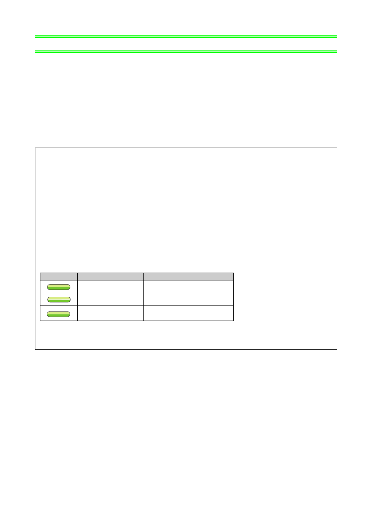
The following marks are used to indicate the controls as below.
(Parameters without any mark are valid for all controls.)
Mark Control method Applied motor (control)
V/F control
Simple magnetic flux
vector control
IPM motor control
Three-phase induction motor
(general-purpose motor control)
Dedicated IPM motor
(IPM motor control)
S
S
IPM
IPM
V/F
V/F
MFVC
MFVC
<Trademarks>
ONWORKS
L
®
is registered trademarks of Echelon Corporation in the U.S.A. and other countries.
Company and product names herein are the trademarks and registered trademarks of their respective owners.
IV
Page 8
Product checking and parts identification
1 OUTLINE
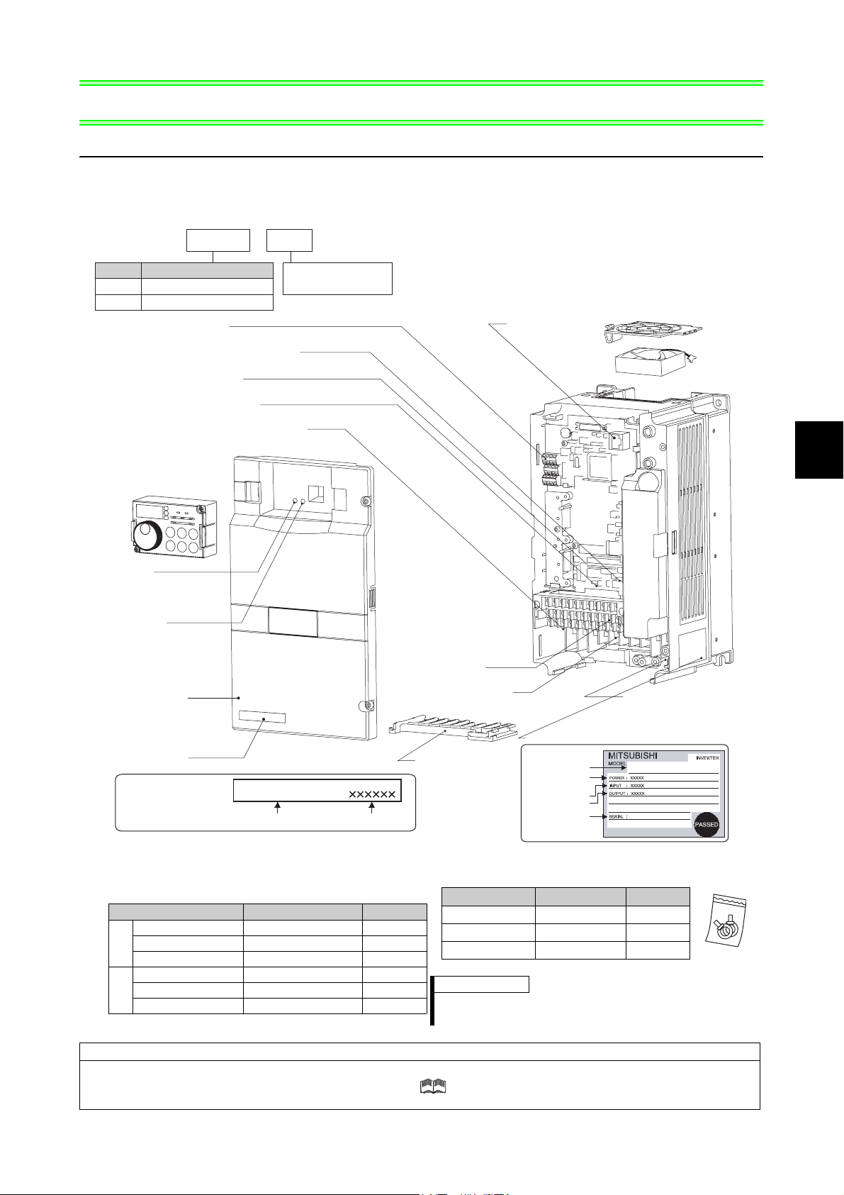
1.1 Product checking and parts identification
Unpack the inverter and check the capacity plate on the front cover and the rating plate on the inverter side face to
ensure that the product agrees with your order and the inverter is intact.
• Inverter Model
FR --F740P
Symbol
F720P
F740P
Connector for plug-in option connection
(Refer to the Instruction Manual of options.)
Voltage/current input switch
(Refer to page 9)
Operation panel (FR-DU07)
(Refer to page 6)
Power lamp
Lit when the control circuit
(R1/L11, S1/L21) is supplied
with power.
Alarm lamp
Lit when the inverter is
in the alarm status
(fault).
Voltage Class
Three-phase 200V class
Three-phase 400V class
RS-485 terminals
(Refer to page 27)
AU/PTC switchover switch
(Refer to Chapter 4 of the Instruction Manual (Applied).)
EMC filter ON/OFF connector
(Refer to page 10)
Front cover
(Refer to page 6)
Capacity plate
Capacity plate
5.5
Represents inverter
capacity (kW)
FR-F740P-5.5K
Inverter model
K
Main circuit terminal block
(Refer to page 20)
Serial number
Control circuit
terminal block
(Refer to page 11)
Combed shaped
wiring cover
(Refer to page 14)
PU connector
(Refer to page 26)
Rating plate
Rating plate
Inverter model
Applied motor
capacity
Input rating
Output rating
Serial number
Cooling fan
(Refer to page 146)
Charge lamp
Lit when power is
supplied to the main
circuit
(Refer to page 11)
FR-F740P-5.5K
1
OUTLINE
• Accessory
· Fan cover fixing screws (30K or lower)
(Refer to page 171)
Capacity Screw Size (mm) Quantity
2.2K to 5.5K M3 × 35 1
7.5K to 15K M4 × 40 2
200V
18.5K to 30K M4 × 50 1
3.7K, 5.5K M3 × 35 1
7.5K to 18.5K M4 × 40 2
400V
22K, 30K M4 × 50 1
· DC reactor supplied (75K or higher)
· Eyebolt for hanging the inverter (37K to 315K)
Capacity Eyebolt Size Quantity
37K M8 2
45K to 160K M10 2
185K to 315K M12 2
REMARKS
·
For removal and reinstallation of covers, refer to page 6.
· For how to find the SERIAL number, refer to page 168.
Harmonic suppression guideline
All models of General-purpose inverters used by specific consumers are covered by "Harmonic suppression guideline for
consumers who receive high voltage or special high voltage". ( For further details, refer to Chapter 3 of the Instruction
Manual (Applied) .)
1
Page 9
Step of operation
Step of operation
p
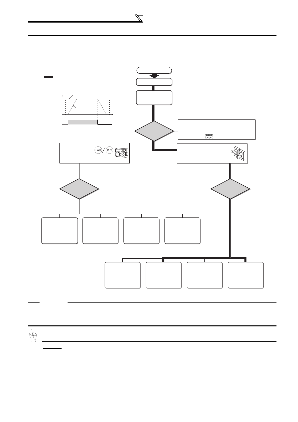
1.2 Step of operation
The inverter needs frequency command and start command. Frequency command (set frequency) determines the
rotation speed of the motor. Turning ON the start command starts the motor to rotate.
Refer to the flow chart below to perform setting.
Step of operation
o
: Initial setting
Installation/mounting
{Refer to page 8}
Frequency command
Inverter
output
Frequency
(Hz)
Frequency
command
Start command with
on the operation panel (PU)
Set from the
PU (FR-DU07/
FR-PU04/FR-PU07).
(PU)
{Refer to page 54} {Refer to page 57} {Refer to page 60} {Refer to page 59}
frequency
ON
How to
give a frequency
command?
Change frequency
with ON/OFF switches
connected to terminals
(multi-speed setting)
Time
(S)
(External) (External) (External)
Wiring of the power
supply and motor
How
to give a start
command?
Perform frequency
setting by a current
output device
(Connection across
terminals 4 and 5)
{Refer to page 11}
Start command using the PU connector and
RS-485 terminal of the inverter and plug-in
option (Communication)
Refer to Chapter 4 of the Instruction Manual (Applied) .
Connect a switch, relay, etc.
to the control circuit
terminal block of the inverter
to give a start command. (External)
Perform frequency
setting by a voltage
output device
(Connection across
terminals 2 and 5)
How to
give a frequency
command?
Set from the
PU (FR-DU07/
FR-PU04/FR-PU07).
(PU) (External) (External) (External)
{Refer to page 61} {Refer to page 65} {Refer to page 69} {Refer to page 67}
Change of frequency
with ON/OFF switches
connected to terminals
(multi-speed setting)
Perform frequency
setting by a current
output device
(Connection across
terminals 4 and 5)
Perform frequency
setting by a voltage
output device
(Connection across
terminals 2 and 5)
CAUTION
Check the following points before powering ON the inverter.
· Check that the inverter is installed correctly in a correct place. (Refer to page 8)
· Check that wiring is correct. (Refer to page 9)
· Check that no load is connected to the motor.
·When protecting the motor from overheat by the inverter, set Pr.9 Electronic thermal O/L relay (Refer to
page 52)
·To drive a general-purpose motor with the rated motor frequency of 50Hz, set Pr.3 Base frequency
(Refer to page 53)
2
Page 10
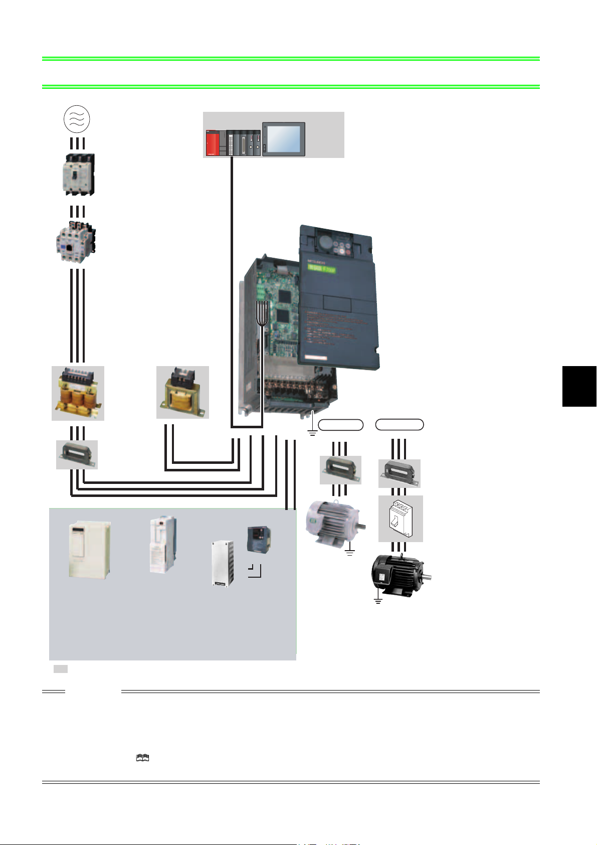
2 INSTALLATION AND WIRING
Three-phase AC power supply
Use within the permissible power supply
specifications of the inverter.
(Refer to page 150)
Moulded case circuit
breaker (MCCB)
or earth leakage circuit
breaker (ELB), fuse
The breaker must be selected carefully since
an in-rush current flows in the inverter at
power on.
(Refer to page 4)
Magnetic contactor(MC)
Install the magnetic contactor to ensure safety.
Do not use this magnetic contactor to start and stop
the inverter.
Doing so will cause the inverter life to be shortened.
(Refer to page 4)
Reactor (FR-HAL, FR-HEL)
Install reactors to suppress harmonics and to
improve the power factor. An AC reactor (FR-HAL)
(option) is required when installing the inverter near
a large power supply system (1000kVA or more).
The inverter may be damaged if you do not use
reactors.
Select the reactor according to the model.
For the 55K or lower, remove the jumpers across
terminals P/+ and P1 to connect to the DC reactor.
(Refer to Chapter 3 of
the Instruction Manual (Applied) .)
AC reactor
(FR-HAL)
DC reactor
(FR-HEL)
EMC filter
(ferrite core)
(FR-BLF)
The 55K or lower has a built-in
common mode choke.
(Refer to Chapter 3 of
the Instruction Manual (Applied) .)
For the 75K or higher, a
DC reactor is supplied.
Always install the reactor.
(Refer to page 36)
Power regeneration
High power factor
converter
*1
, MT-HC*2)
(FR-HC
Power supply harmonics
can be greatly suppressed.
Install this as required.
(Refer to page 32) (Refer to page 34 and 35)
*1 Compatible with the 55K or lower.
*2 Compatible with the 75K or higher.
: Install these options as required.
common converter
*1
)
(FR-CV
Power regeneration
converter (MT-RC
Greater braking capability
is obtained.
Install this as required.
*2
)
Programmable
controller
POWER
MODE
RUN
ERR
USER
BAT
BOOT
PULL
USB
PULL
Human machine interface
RUN
MNG
RUN
MNG
T.PASS
D.LINK
T.PASS
D.LINK
SD
RD
SD
RD
ERR
ERR
ERR
ERR
RS-485 terminal block
The inverter can be connected with a
computer such as a programmable
controller and with GOT (human
machine interface).
They support Mitsubishi inverter
protocol and Modbus-RTU (binary)
protocol.
R/L1 S/L2 T/L3
P/+
P1
Brake unit
*1
P/+
PR
, MT-BU5*2)
PR
P/+
(FR-BU2, FR-BU
Resistor unit
*1
, MT-BR5*2)
(FR-BR
The regeneration braking
capability of the inverter can be
exhibited fully.
Install this as required.
(Refer to page 28)
Inverter (FR-F700P)
The life of the inverter is influenced by surrounding
air temperature. The surrounding air temperature
should be as low as possible within the permissible
range. Especially when mounting the inverter
inside an enclosure, take cautions of the
surrounding air temperature. (Refer to page 8)
Wrong wiring might lead to damage of the inverter.
The control signal lines must be kept fully away
from the main circuit to protect them from noise.
(Refer to page 9)
Refer to page 10 for the built-in EMC filter.
IPM connection
U VW
N/-P/+
Earth
IM connection
UVW
(Ground)
Generalpurpose
motor
Earth
(Ground)
Devices connected
to the output
Do not install a power
factor correction capacitor,
surge suppressor or EMC filter (capacitor) on the
output side of the inverter.
When installing a moulded case circuit breaker on
the output side of the inverter, contact each
manufacturer for selection of the moulded case
circuit breaker.
Earth (Ground)
To prevent an electric shock, always earth
(ground) the motor and inverter.
Earth
(Ground)
EMC filter
(ferrite core)
(FR-BSF01, FR-BLF)
Install an EMC filter (ferrite
core) to reduce the
electromagnetic noise
generated from the inverter.
Effective in the range from
about 0.5MHz to 5MHz.
A wire should be wound four
turns at a maximum.
(Refer to Chapter 3 of the
Instruction Manual (Applied) .)
Contactor
Example) No-fuse
switch (DSN type)
Install a contactor in an
application where the IPM
motor is driven by the load
even at power-OFF of the
inverter. Do not open or
close the contactor while
the inverter is running
(outputting).
Dedicated IPM motor
(MM-EFS, MM-EF)
Use the specified motor.
IPM motors cannot be driven
by the commercial power
supply.
(Refer to page 163 and 164)
2
INSTALLATION AND WIRING
CAUTION
· Do not install a power factor correction capacitor, surge suppressor or capacitor type filter on the inverter output side. This will
cause the inverter to trip or the capacitor, and surge suppressor to be damaged. If any of the above devices are connected,
immediately remove them.
· Electromagnetic wave interference
The input/output (main circuit) of the inverter includes high frequency components, which may interfere with the communication
devices (such as AM radios) used near the inverter. In this case, set the EMC filter valid to minimize interference.
(Refer to Chapter 2 of the Instruction Manual (Applied).)
· Refer to the instruction manual of each option and peripheral devices for details of peripheral devices.
· An IPM motor cannot be driven by the commercial power supply.
3
Page 11
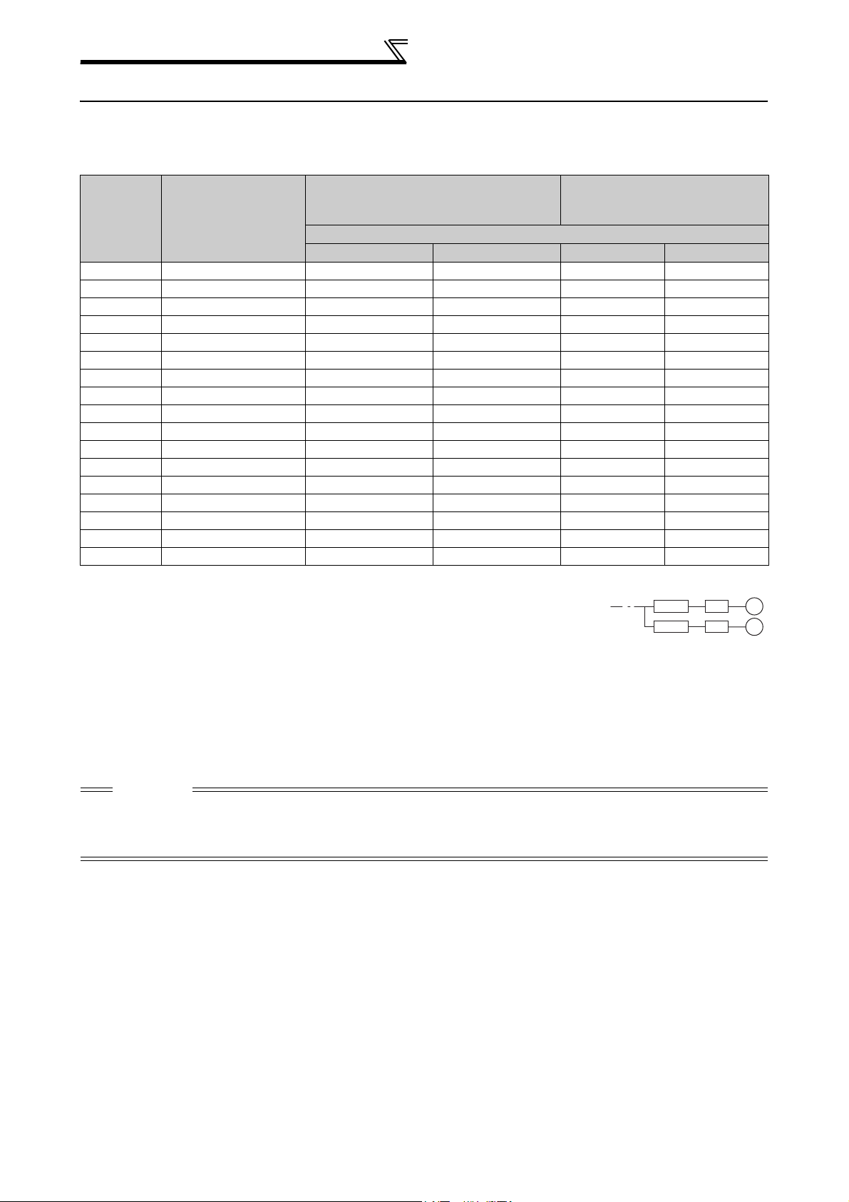
Peripheral devices
2.1 Peripheral devices
Check the inverter model of the inverter you purchased. Appropriate peripheral devices must be selected according
to the capacity. Refer to the following list and prepare appropriate peripheral devices:
200V class
Moulded Case Circuit Breaker (MCCB) *2
Motor
Output (kW)
*1
Applicable Inverter
Model
or Earth Leakage Circuit Breaker (ELB)
(NF or NV type)
Power factor improving (AC or DC) reactor
Without With Without With
0.75 FR-F720P-0.75K 10A 10A S-N10 S-N10
1.5 FR-F720P-1.5K 15A 15A S-N10 S-N10
2.2 FR-F720P-2.2K 20A 15A S-N10 S-N10
3.7 FR-F720P-3.7K 30A 30A S-N20, S-N21 S-N10
5.5 FR-F720P-5.5K 50A 40A S-N25 S-N20, S-N21
7.5 FR-F720P-7.5K 60A 50A S-N25 S-N25
11 FR-F720P-11K 75A 75A S-N35 S-N35
15 FR-F720P-15K 125A 100A S-N50 S-N50
18.5 FR-F720P-18.5K 150A 125A S-N65 S-N50
22 FR-F720P-22K 175A 150A S-N80 S-N65
30 FR-F720P-30K 225A 175A S-N95 S-N80
37 FR-F720P-37K 250A 225A S-N150 S-N125
45 FR-F720P-45K 300A 300A S-N180 S-N150
55 FR-F720P-55K 400A 350A S-N220 S-N180
75 FR-F720P-75K ⎯ 400A ⎯
90 FR-F720P-90K ⎯ 400A ⎯
110 FR-F720P-110K ⎯ 500A ⎯
*1 Selections for use of the Mitsubishi 4-pole standard motor with power supply voltage of 200VAC 50Hz.
*2 Select the MCCB according to the power supply capacity.
Install one MCCB per inverter.
For using commercial-power supply operation, select a breaker with capacity which allows the motor to be
directly power supplied.
For installation in the United States, Class RK5, Class J, Class CC, Class L, Class T or any faster acting
fuses or UL 489 Molded Case Circuit Breaker (MCCB) must be provided, in accordance with the National
Electrical Code and any applicable local codes.
For installation in Canada, Class RK5, Class J, Class CC, Class L, Class T or any faster acting fuses or UL
489 Molded Case Circuit Breaker (MCCB) must be provided, in accordance with the Canada Electrical
Code and any applicable provincial codes. (Refer to page 169.)
*3 Magnetic contactor is selected based on the AC-1 class. The electrical durability of magnetic contactor is 500,000 times. When the magnetic
contactor is used for emergency stop during motor driving, the electrical durability is 25 times.
When using the MC for emergency stop during motor driving or using on the motor side during commercial-power supply operation, select the
MC with class AC-3 rated current for the motor rated current.
Input Side Magnetic Contactor*3
S-N300
S-N300
S-N400
MCCB INV
MCCB INV
M
M
CAUTION
⋅ When the inverter capacity is larger than the motor capacity, select an MCCB and a magnetic contactor according to the
inverter model, and select cable and reactor according to the motor output.
⋅ When the breaker on the inverter primary side trips, check for the wiring fault (short circuit), damage to internal parts of the
inverter, etc. Identify the cause of the trip, then remove the cause and power ON the breaker.
4
Page 12
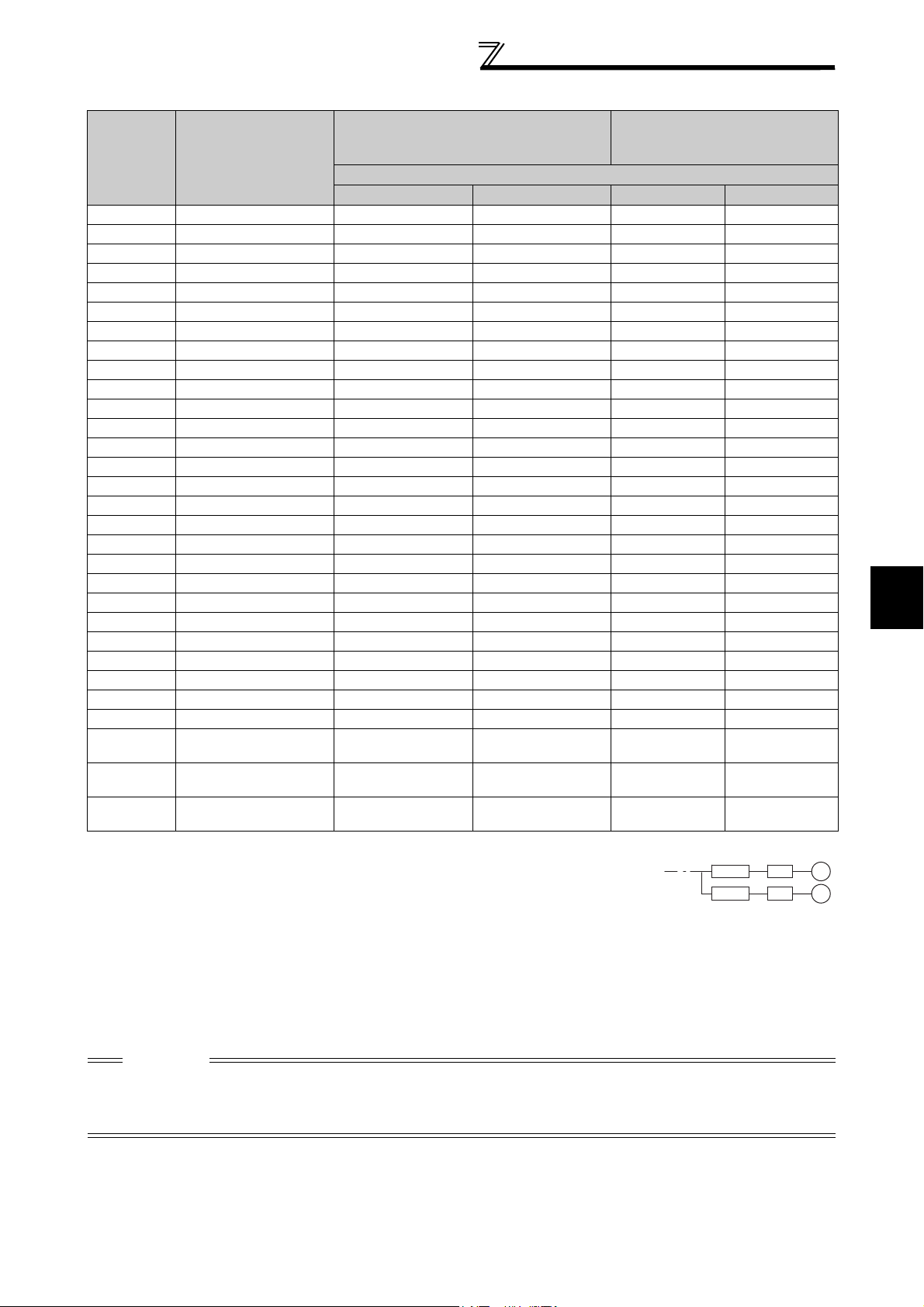
Peripheral devices
400V class
Motor
Output
(kW)
*1
Applicable Inverter
Model
0.75 FR-F740P-0.75K 5A 5A S-N10 S-N10
1.5 FR-F740P-1.5K 10A 10A S-N10 S-N10
2.2 FR-F740P-2.2K 10A 10A S-N10 S-N10
3.7 FR-F740P-3.7K 20A 15A S-N10 S-N10
5.5 FR-F740P-5.5K 30A 20A S-N20, S-N21 S-N11, S-N12
7.5 FR-F740P-7.5K 30A 30A S-N20, S-N21 S-N20, S-N21
11 FR-F740P-11K 50A 40A S-N20, S-N21 S-N20, S-N21
15 FR-F740P-15K 60A 50A S-N25 S-N20, S-N21
18.5 FR-F740P-18.5K 75A 60A S-N25 S-N25
22 FR-F740P-22K 100A 75A S-N35 S-N25
30 FR-F740P-30K 125A 100A S-N50 S-N50
37 FR-F740P-37K 150A 125A S-N65 S-N50
45 FR-F740P-45K 175A 150A S-N80 S-N65
55 FR-F740P-55K 200A 175A S-N80 S-N80
75 FR-F740P-75K ⎯ 225A ⎯ S-N95
90 FR-F740P-90K ⎯ 225A ⎯ S-N150
110 FR-F740P-110K ⎯ 225A ⎯ S-N180
132 FR-F740P-132K ⎯ 400A ⎯ S-N220
150 FR-F740P-160K ⎯ 400A ⎯ S-N300
160 FR-F740P-160K ⎯ 400A ⎯ S-N300
185 FR-F740P-185K ⎯ 400A ⎯ S-N300
220 FR-F740P-220K ⎯ 500A ⎯ S-N400
250 FR-F740P-250K ⎯ 600A ⎯ S-N600
280 FR-F740P-280K ⎯ 600A ⎯ S-N600
315 FR-F740P-315K ⎯ 700A ⎯ S-N600
355 FR-F740P-355K ⎯ 800A ⎯ S-N600
400 FR-F740P-400K ⎯ 900A ⎯ S-N800
450 FR-F740P-450K ⎯ 1000A ⎯
500 FR-F740P-500K ⎯ 1200A ⎯
560 FR-F740P-560K ⎯ 1500A ⎯
*1 Selections for use of the Mitsubishi 4-pole standard motor with power supply voltage of 400VAC 50Hz.
*2 Select the MCCB according to the power supply capacity.
Install one MCCB per inverter.
For using commercial-power supply operation, select a breaker with capacity which allows the motor to be
directly power supplied.
For installation in the United States, Class RK5, Class J, Class CC, Class L, Class T or any faster acting
fuses or UL 489 Molded Case Circuit Breaker (MCCB) must be provided, in accordance with the National
Electrical Code and any applicable local codes.
For installation in Canada, Class RK5, Class J, Class CC, Class L, Class T or any faster acting fuses or UL
489 Molded Case Circuit Breaker (MCCB) must be provided, in accordance with the Canada Electrical
Code and any applicable provincial codes. (Refer to page 169.)
*3 Magnetic contactor is selected based on the AC-1 class. The electrical durability of magnetic contactor is 500,000 times. When the magnetic
contactor is used for emergency stop during motor driving, the electrical durability is 25 times.
When using the MC for emergency stop during motor driving or using on the motor side during commercial-power supply operation, select the
MC with class AC-3 rated current for the motor rated current.
CAUTION
⋅ When the inverter capacity is larger than the motor capacity, select an MCCB and a magnetic contactor according to the
inverter model, and select cable and reactor according to the motor output.
⋅ When the breaker on the inverter primary side trips, check for the wiring fault (short circuit), damage to internal parts of the
inverter, etc. Identify the cause of the trip, then remove the cause and power ON the breaker.
Moulded Case Circuit Breaker (MCCB) *2
or Earth Leakage Circuit Breaker (ELB)
Input Side Magnetic Contactor*3
(NF or NV type)
Power factor improving (AC or DC) reactor
Without With Without With
1000A
Rated product
1000A
Rated product
1200A
Rated product
MCCB INV
MCCB INV
M
M
2
INSTALLATION AND WIRING
5
Page 13
Method of removal and reinstallation of the
front cover
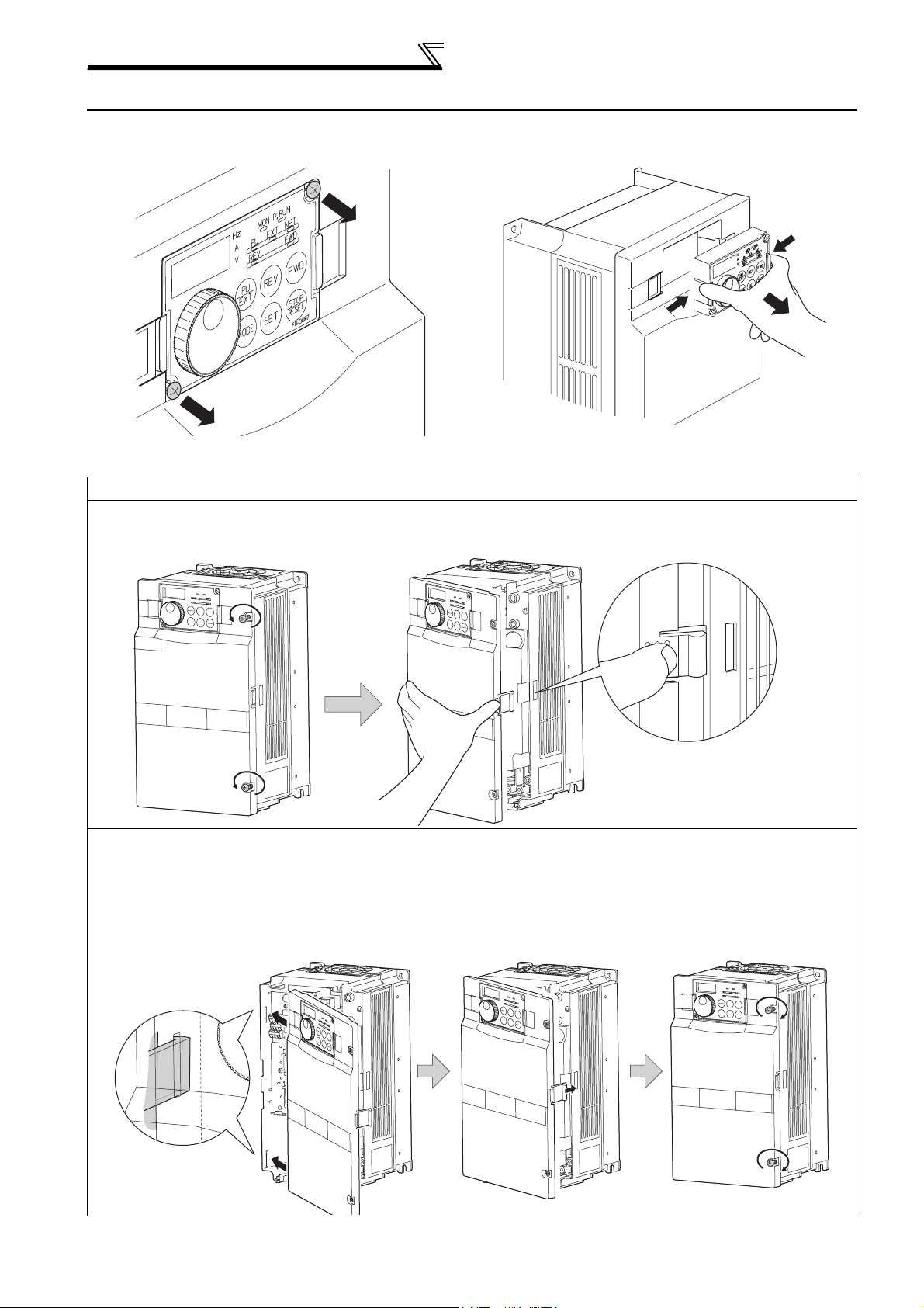
2.2 Method of removal and reinstallation of the front cover
•Removal of the operation panel
1) Loosen the two screws on the operation panel.
(These screws cannot be removed.)
When reinstalling the operation panel, insert it straight to reinstall securely and tighten the fixed screws of the
operation panel.
2) Push the left and right hooks of the operation panel
and pull the operation panel toward you to remove.
FR-F720P-30K or lower, FR-F740P-30K or lower
•
Removal
1) Loosen the installation screws of the
front cover.
Front cover
2) Pull the front cover toward you to remove by pushing an
installation hook using left fixed hooks as supports.
Front cover
•Reinstallation
1) Insert the two fixed hooks on the left side of
the front cover into the sockets of the
inverter.
2) Using the fixed hooks as supports,
securely press the front cover
against the inverter.
(Although installation can be done
with the operation panel mounted,
make sure that a connector is
securely fixed.)
Installation hook
3) Tighten the installation
screws and fix the front
cover.
Front cover
Front cover
Front cover
6
Page 14
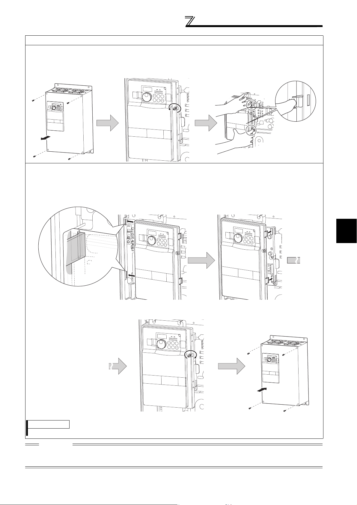
FR-F720P-37K or higher, FR-F740P-37K or higher
•
Removal
1) Remove installation screws on
the front cover 1 to remove the
2) Loosen the installation
screws of the front cover 2.
front cover 1.
Front cover 1
Front cover 2
•Reinstallation
1) Insert the two fixed hooks on the left side of the
front cover 2 into the sockets of the inverter.
Method of removal and reinstallation of the
front cover
3) Pull the front cover 2 toward you to
remove by pushing an installation
hook on the right side using left
fixed hooks as supports.
Installation hook
2) Using the fixed hooks as supports, securely
press the front cover 2 against the inverter.
(Although installation can be done with the
operation panel mounted, make sure that a
connector is securely fixed.)
Front cover 2 Front cover 2
3) Fix the front cover 2 with the
installation screws.
Front cover 2
2
4) Fix the front cover 1 with the
installation screws.
INSTALLATION AND WIRING
Front cover 1
REMARKS
⋅ For the FR-F740P-185K or higher, the front cover 1 is separated into two parts.
CAUTION
Fully make sure that the front cover has been reinstalled securely. Always tighten the installation screws of the front cover.
The same serial number is printed on the capacity plate of the front cover and the rating plate of the inverter. Before reinstalling the
front cover, check the serial numbers to ensure that the cover removed is reinstalled to the inverter from where it was removed.
7
Page 15
Installation of the inverter and instructions
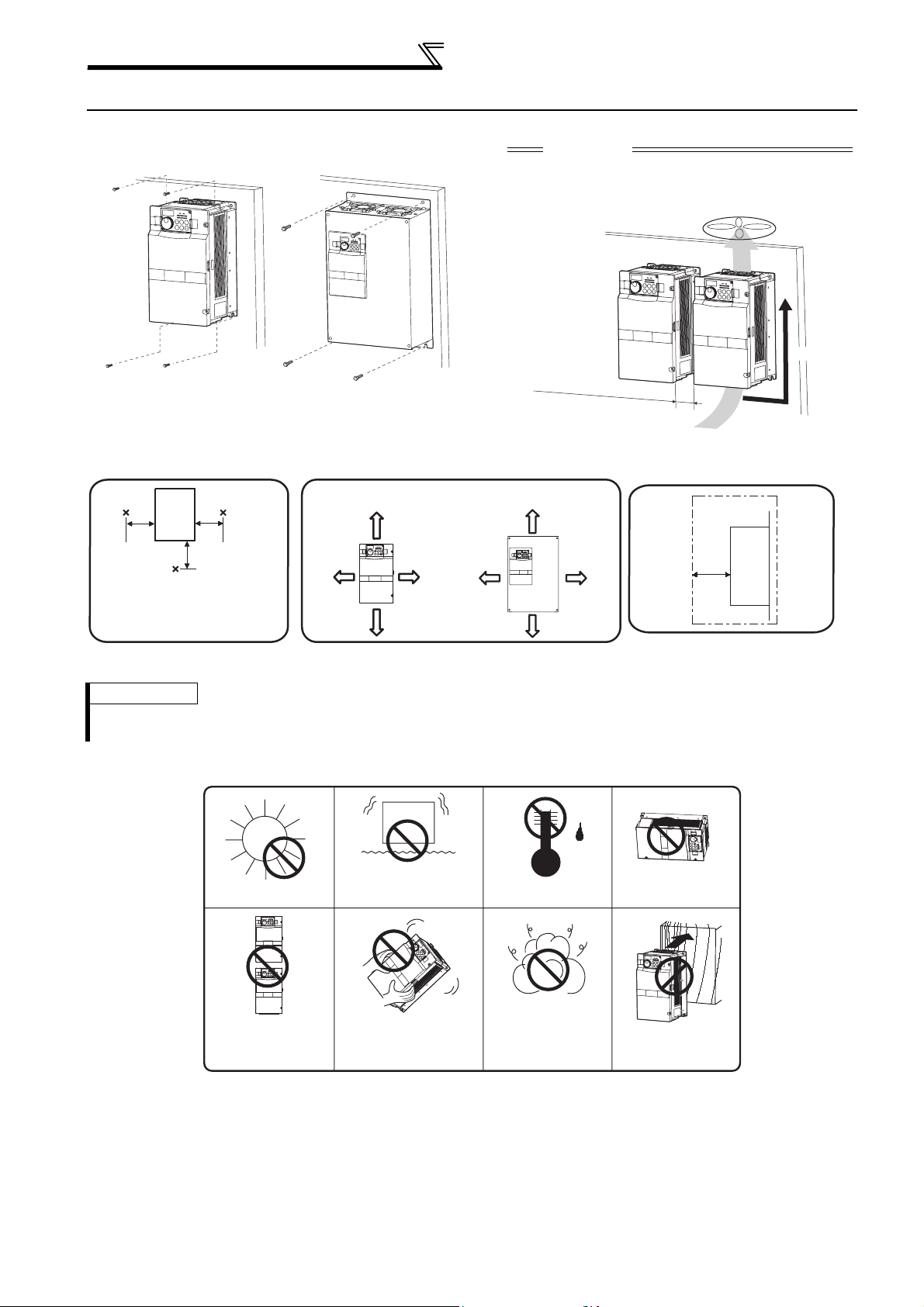
2.3 Installation of the inverter and instructions
• Installation of the Inverter
Installation on the enclosure
30K or lower 37K or higher
CAUTION
⋅ When encasing multiple inverters, install them in
parallel as a cooling measure.
⋅ Install the inverter vertically.
Vertical
Fix six points for the FR-F740P-185K
to 400K and fix eight points for the
FR-F740P-450K to 560K.
Refer to the clearances below.
• Install the inverter under the following conditions.
Surrounding air temperature and humidity
Measurement
position
Inverter
5cm
Measurement
position
5cm
5cm
Temperature: -10°C to 50°C
Humidity: 90% RH maximum
Leave enough clearances as a
cooling measure.
Clearances
55K or lower 75K or higher
10cm or more
5cm
or more *
5cm
or more *
10cm or more
*1cm or more for 3.7K or lower
(front)
10cm
or more
20cm or more
10cm
or more
20cm or more
Clearances (side)
Inverter
5cm
or more
*
*1cm or more for 3.7K or lower
REMARKS
•
For replacing the cooling fan of the FR-F740P-185K or higher, 30cm of space is necessary in front of the inverter.
Refer to page 146 for fan replacement.
• The inverter consists of precision mechanical and electronic parts. Never install or handle it in any of the following
conditions as doing so could cause an operation fault or failure.
Direct sunlight
Vertical mounting
(When installing two or
more inverters, install
them in parallel.)
Vibration(5.9m/s2 * or mor e at 1 0 to
55Hz (directions of X, Y, Z axes))
*2.9m/s2 or more for the 185K or
higher
Transportation by
holding the front cover
High temperature,
high humidity
Oil mist, flammable
gas, corrosive gas,
fluff, dust, etc.
Horizontal placement
Mounting to
combustible material
8
Page 16
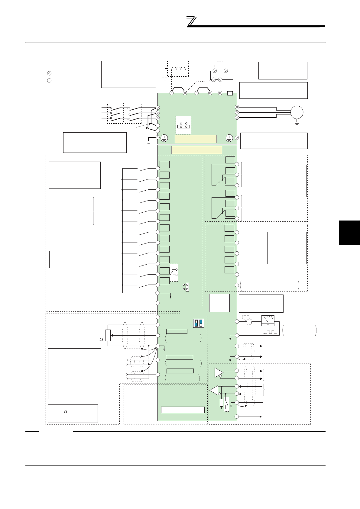
2.4 Wiring
2.4.1 Terminal connection diagram
Wiring
*7
N/-
*8
RUN
PU
connector
TXD+
TXD-
RXD+
RXD-
resistor
VCC
Resistor unit
(Option)
Brake unit
(Option)
*7.
CN8
*6
U
V
W
C1
B1
A1
C2
B2
A2
Running
SU
Up to frequency
IPF
Instantaneous
power failure
OL
Overload
FU
Frequency detection
SE
*
9. It is not necessary
FM
SD
AM
5
SG
*6. A CN8 (for MT-BU5)
connector is provided
with the 75K or higher.
Do not use PR and PX terminals.
Please do not remove the jumper
connected to terminal PR and PX.
*8.
The 200V class 0.75K and 1.5K
are not provided with the ON/OFF
connector EMC filter.
Relay output 1
(Fault output)
Relay output 2
Open collector output common
Sink
/
source common
when calibrating the
indicator from the
operation panel.
+-
Calibration
resistor *9
(+)
(-)
5V
Motor
M
Earth
(ground)
cable
Relay output
Terminal functions
vary with the output
terminal assignment
(Pr. 195, Pr. 196)
(Refer to Chapter 4 of
the Instruction Manual
(Applied))
Open collector output
Terminal functions
vary with the output
terminal assignment
(Pr. 190 to Pr. 194)
(Refer to Chapter 4 of
the Instruction Manual
(Applied))
Indicator
(Frequency meter, etc.)
Moving-coil type
1mA full-scale
Analog signal output
(0 to 10VDC)
RS-485 terminals
Data transmission
Data reception
GND
(Permissible load
current 100mA)
Sink logic
Main circuit terminal
Control circuit terminal
Three-phase AC
power supply
*2. To supply power to the
control circuit separately,
remove the jumper across
R1/L11 and S1/L21.
Control input signals (No voltage input allowed)
Terminal functions vary
with the input terminal
assignment
(Pr. 178 to Pr. 189)
(Refer to Chapter 4 of the
Instruction Manual (Applied))
Start self-holding selection
Multi-speed
selection
Second function selection
*3. AU terminal can be
used as PTC input
terminal.
Terminal 4 input selection
(Current input selection)
Selection of automatic restart
Contact input common
(Common for external power supply transistor)
Frequency setting signal (Analog)
Frequency setting
potentiometer
*
4. Terminal input specifications
can be changed by analog
input specifications switchover
(Pr. 73, Pr. 267). Set the
voltage/current input switch in
the OFF position to select
voltage input (0 to 5V/0 to
10V) and ON to select current
input (0 to 20mA).
(Refer to Chapter 4 of the
Instruction Manual (Applied))
*
5. It is recommended to use
2W1k when the
frequency setting signal is
changed frequently.
*1. DC reactor (FR-HEL)
Be sure to connect the DC reactor
supplied with the 75K or higher.
When a DC reactor is connected
to the 55K or lower, remove the
jumper across P1 and P/+.
MCCB
Forward
rotation
start
Reverse
rotation
start
High speed
Middle speed
Low speed
Jog operation
Output stop
Reset
after instantaneous
power failure
24VDC power supply
3
2
1/2W1k
*5
1
Auxiliary
input
Terminal
4 input
(Current
input)
MC
Jumper
Earth
(Ground)
(+)
(-)
(+)
(-)
Connector
for plug-in option
connection
*1
Earth
Jumper
(ground)
P1
R/L1
S/L2
T/L3
*2
R1/L11
S1/L21
P/+
ON
OFF
Jumper
PR
*7
EMC filter
ON/OFF
connector
PX
Main circuit
Control circuit
STF
STR
STOP
RH
RM
RL
JOG
RT
MRS
RES
*3
AU
AU
PTC
CS
SD
PC
10E(+10V)
10(+5V)
0 to 5VDC
2
0 to 10VDC
0 to 20mADC
5
(Analog common)
0 to ±10VDC
1
0 to ±5VDC
4 to 20mADC
4
0 to 5VDC
0 to 10VDC
Option connector 1
SINK
SOURCE
*4
Voltage/current
input switch
4
ON
OFF
Initial value
selectable
Initial
value
selectable
Initial
value
selectable
2
*
4
*
4
*
4
Terminating
CAUTION
· To prevent a malfunction due to noise, keep the signal cables more than 10cm away from the power cables. Also separate the
main circuit wire of the input side and the output side.
· After wiring, wire offcuts must not be left in the inverter.
Wire offcuts can cause an alarm, failure or malfunction. Always keep the inverter clean.
When drilling mounting holes in an enclosure etc. take care not to allow chips and other foreign matter to enter the inverter.
· Set the voltage/current input switch correctly. Operation with a wrong setting may cause a fault, failure or malfunction.
2
INSTALLATION AND WIRING
9
Page 17
Wiring
r
r
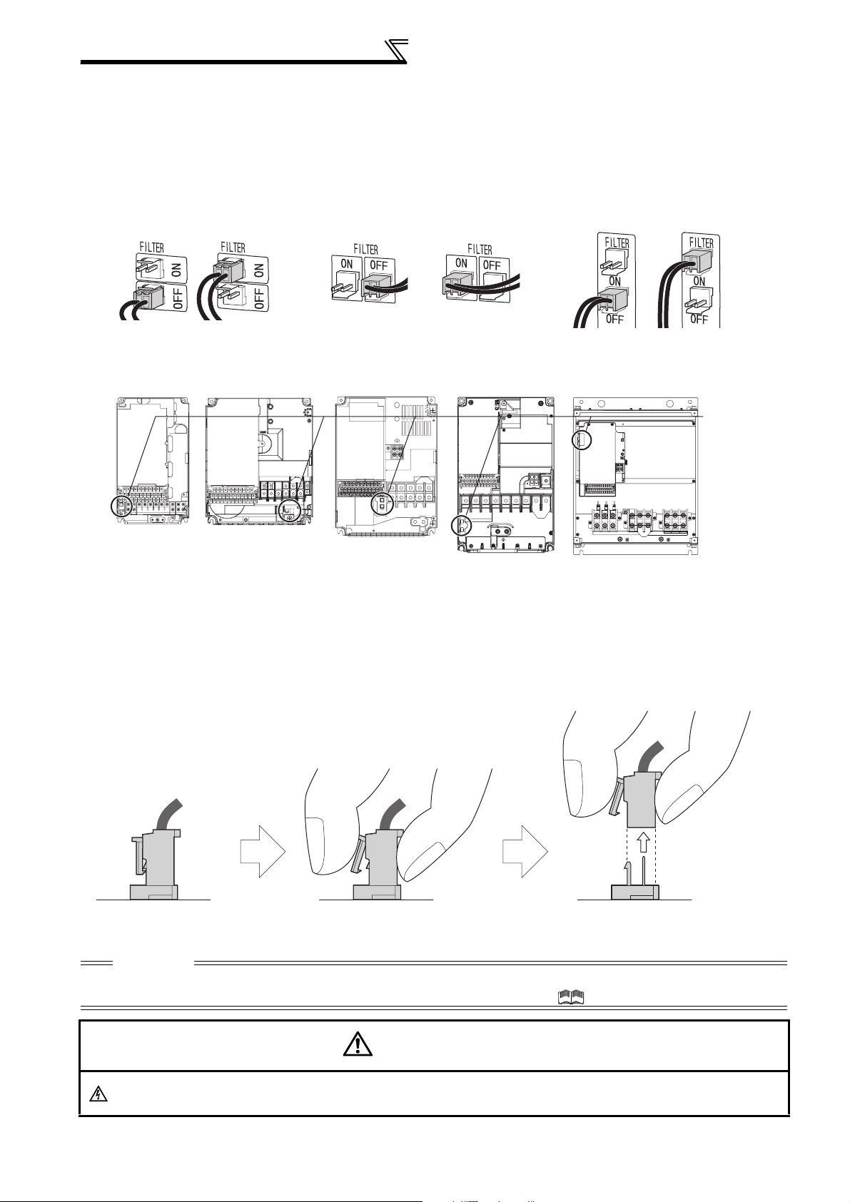
2.4.2 EMC filter
This inverter is equipped with a built-in EMC filter (capacitive filter) and common mode choke.
The EMC filter is effective for reduction of air-propagated noise on the input side of the inverter.
The EMC filter is factory-set to disable (OFF). To enable it, fit the EMC filter ON/OFF connector to the ON position.
The input side common mode choke, built-in the 55K or lower inverter, is always valid regardless of ON/OFF of the
EMC filter ON/OFF connector.
5.5K or lower
EMC filter OFF EMC filter OFF EMC filter OFFEMC filter ON EMC filter ON EMC filter ON
(initial setting) (initial setting) (initial setting)
FR-F720P-2.2K to 5.5K
FR-F740P-0.75K to 5.5K
FR-F720P-7.5K, 11K
FR-F740P-7.5K, 11K
FR-F740P-15K, 18.5K
7.5K, 11K
FR-F720P-15K
FR-F720P-18.5K to 30K
FR-F740P-22K, 30K
15K or higher
FR-F720P-37K or higher
FR-F740P-37K or higher
EMC filte
ON/OFF
connecto
VUW
The FR-F720P-0.75K and 1.5K are not provided with the EMC filter ON/OFF connector. (Always ON)
<How to disconnect the connector>
(1) Before removing a front cover, check to make sure that the indication of the inverter operation panel is OFF, wait
for at least 10 minutes after the power supply has been switched OFF, and check that there are no residual voltage
using a tester or the like. (For the front cover removal method, refer to page 6.)
(2) When disconnecting the connector, push the fixing tab and pull the connector straight without pulling the cable or
forcibly pulling the connector with the tab fixed. When installing the connector, also engage the fixing tab securely.
If it is difficult to disconnect the connector, use a pair of long-nose pliers, etc.
EMC filter
ON/OFF connector
(Side view)
Disengage connector fixing tab. With tab disengaged,
pull up connector straight.
CAUTION
⋅ Fit the connector to either ON or OFF.
⋅ Enabling (turning ON) the EMC filter increases leakage current. (Refer to Chapter 3 of the Instruction Manual (Applied))
WARNING
While power is ON or when the inverter is running, do not open the front cover. Otherwise you may get an electric shock.
10
Page 18
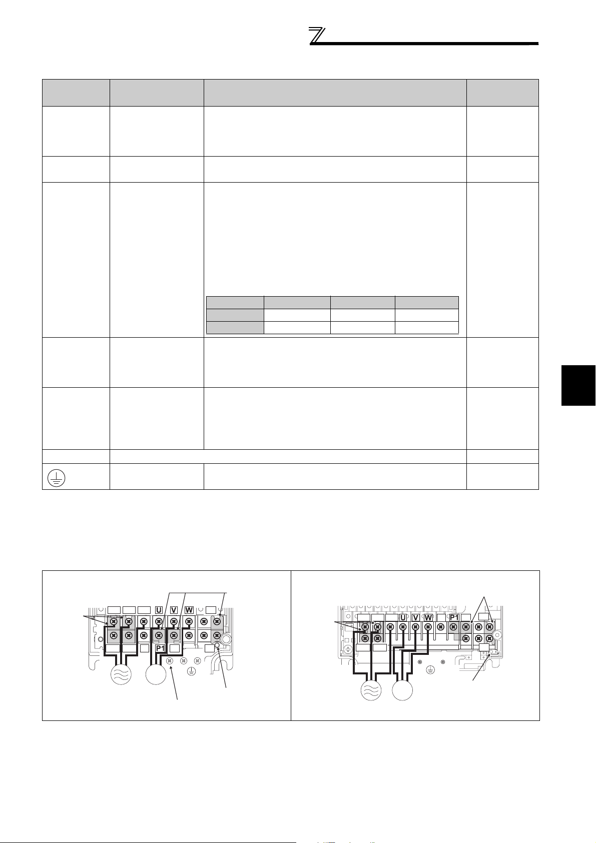
2.4.3 Specification of main circuit terminal
Wiring
Term inal
Symbol
R/L1,
S/L2,
T/L3
U, V, W Inverter output
Term inal Name Description
Connect to the commercial power supply.
AC power input
Keep these terminals open when using the high power
factor converter (FR-HC, MT-HC) or power regeneration
common converter (FR-CV).
Connect a three-phase squirrel-cage motor or dedicated
IPM motor.
Connected to the AC power supply terminals R/L1 and S/
L2. To retain the fault display and fault output or when
using the high power factor converter (FR-HC, MT-HC) or
power regeneration common converter (FR-CV), remove
the jumpers from terminals R/L1 and R1/L11, and S/L2
R1/L11,
S1/L21
Power supply for
control circuit
and S1/L21, and apply external power to these terminals.
The power capacity necessary when separate power is
supplied from R1/L11 and S1/L21 differs according to the
inverter capacity.
15K or lower 18.5K 22K or higher
200V class 60VA 80VA 80VA
400V class 60VA 60VA 80VA
Connect the brake unit (FR-BU2, FR-BU, BU and MT-
P/+, N/-
Brake unit
connection
BU5), power regeneration common converter (FR-CV),
high power factor converter (FR-HC and MT-HC) or power
regeneration converter (MT-RC).
For the 55K or lower, remove the jumper across terminals
P/+ and P1, and connect the DC reactor. (Be sure to
connect the DC reactor supplied with the 75K or higher.)
When a DC reactor is not connected, the jumper across
P/+, P1
DC reactor
connection
terminals P/+ and P1 should not be removed.
PR, PX Please do not remove or use terminals PR and PX or the jumper connected.
Earth (ground)
For earthing (grounding) the inverter chassis. Must be
earthed (grounded).
Refer to
Page
11
11
18
28
2
36
—
17
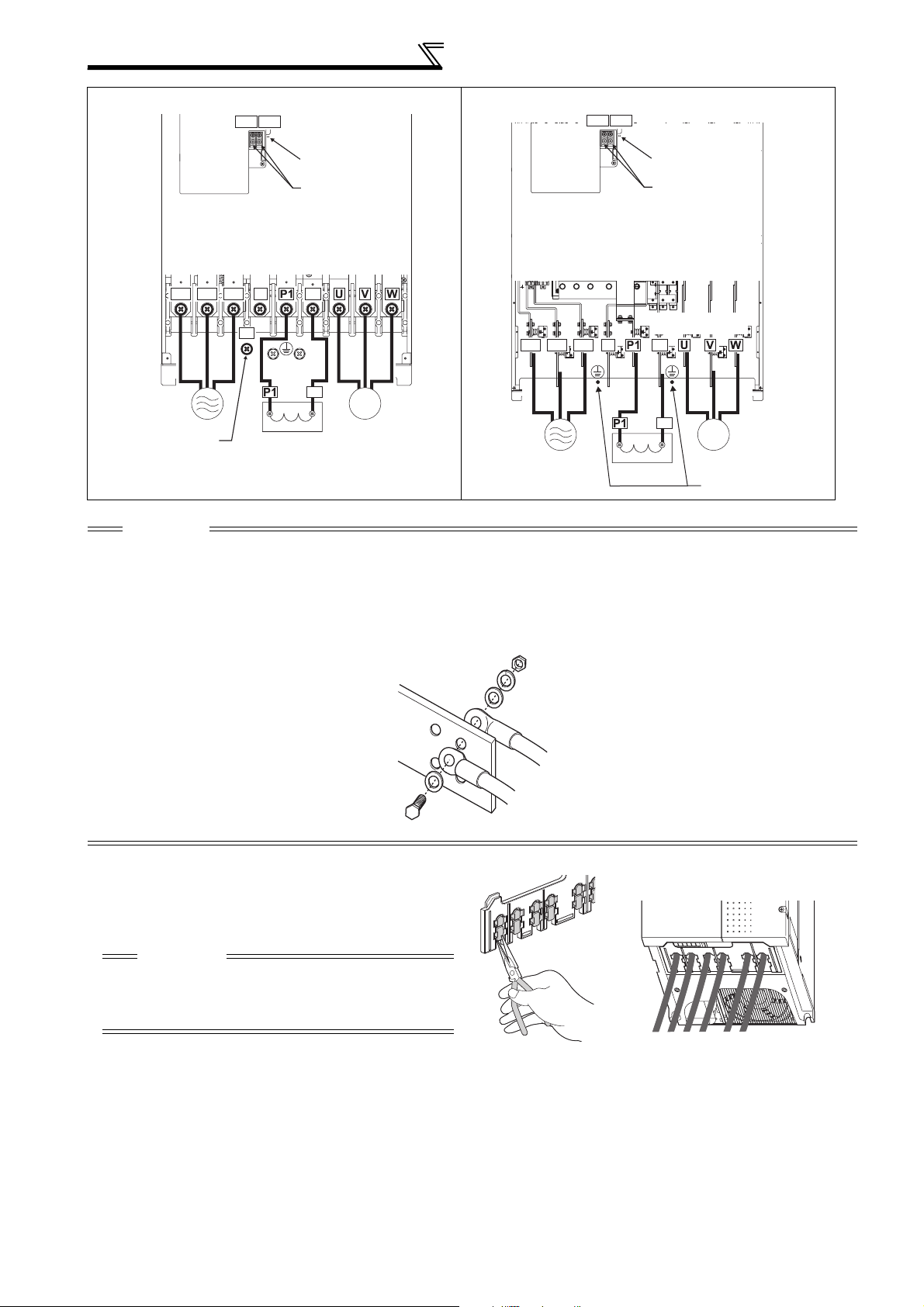
2.4.4 Terminal arrangement of the main circuit terminal, power supply and the motor wiring
200V class
FR-F720P-0.75K, 1.5K FR-F720P-2.2K to 5.5K
Jumper
PR
P/+
PX
Charge lamp
Jumper
Screw size (M4)
R/L1
S/L2
R1/L11
S1/L21
Power supply
Jumper
T/L3
N/-
P/+
M
Motor
As this is an inside cover fixing screw,
do not remove it.
PX
Screw size
(M4)
PR
Charge lamp
Jumper
Screw size (M4)
R/L1 S/L2 T/L3
R1/L11 S1/L21
Power
supply
M
Motor
N/-
Screw size
(M4)
INSTALLATION AND WIRING
11
Page 19
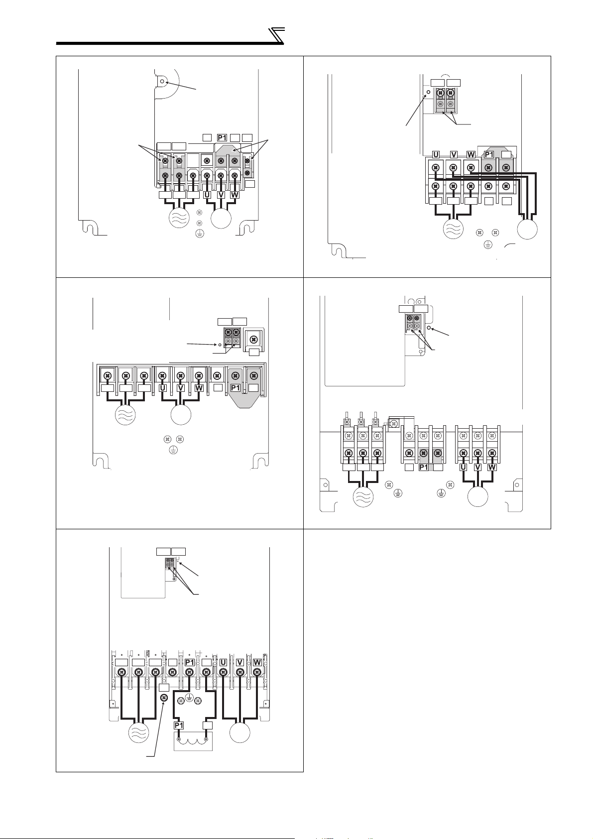
Wiring
r
FR-F720P-7.5K, 11K FR-F720P-15K
Charge lamp
Jumper
Screw size
(M5)
**
R1/L11 S1/L21
R/L1 S/L2 T/L3
N/-
P/+
*
PR
PX
*
Jumpe
Charge lamp
Screw size (M5)
M
Power supply
* Screw size of terminal
R1/L11, S1/L21, PR
and PX is M4.
Screw size (M5)
FR-F720P-18.5K to 30K FR-F720P-37K to 55K
Screw size
(M6 for 18.5K,
M8 for 22K and 30K)
Screw size (M4)
Charge lamp
Jumper
Motor
R1/L11 S1/L21
Screw size
(M4)
PR
R/L1 S/L2 T/L3
R1/L11 S1/L21
R1/L11 S1/L21
Screw size
Power supply
Screw size (M5)
Charge lamp
Jumper
(M4)
Jumper
Jumper
N/-
P/+
PR
M
Motor
R/L1 S/L2 T/L3
Power supply
FR-F720P-75K to 110K
R/L1 S/L2 T/L3
M
Motor
Screw size (M6)
R1/L11 S1/L21
Screw size (M4)
N/-
N/-
Jumper
Charge lamp
Jumper
Screw size (M12)
P/+
P/+
R/L1 S/L2 T/L3
Power
supply
Screw size
(M8 for 37K, M10 for 45K and 55K)
N/-
P/+
Jumper
Screw size
(M6 for 37K,
M8 for 45K and 55K)
M
Motor
12
Power supply
Screw size (M12)
(for option)
P/+
Screw size
(M10)
P/+
DC reactor
M
Motor
Page 20
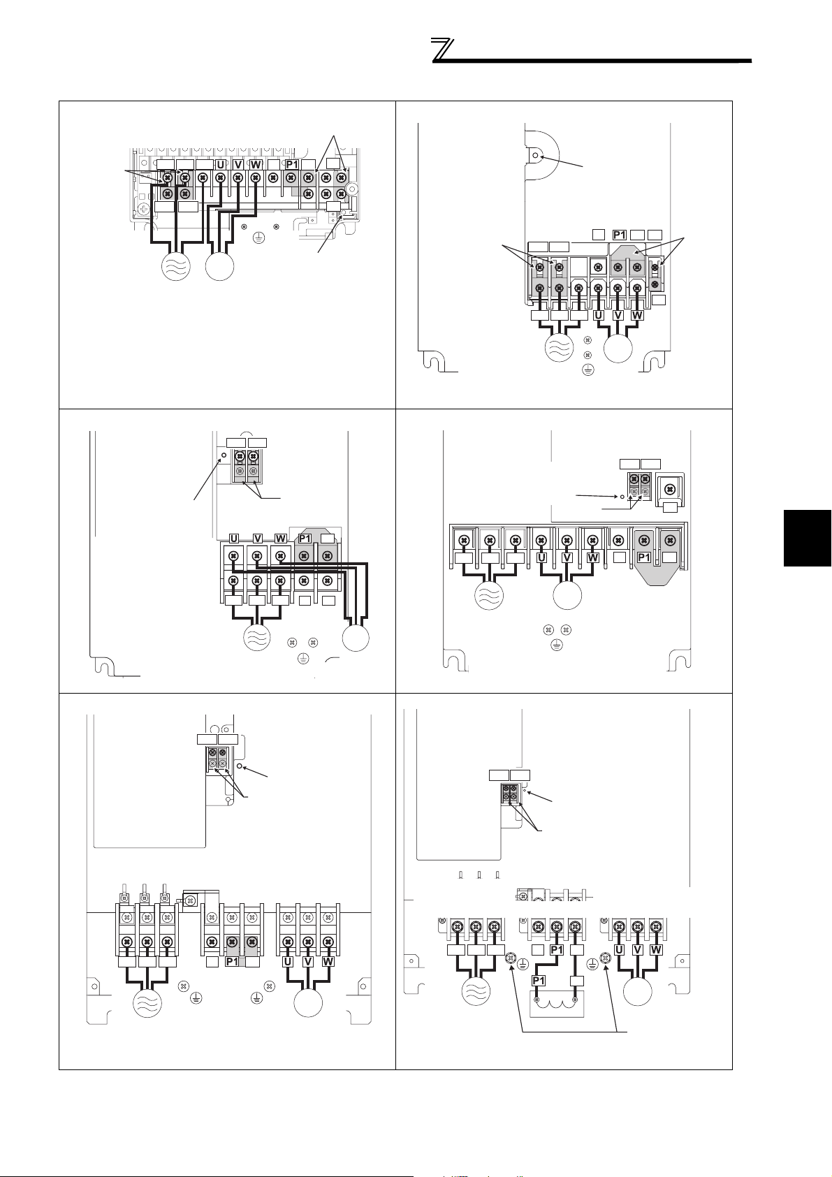
400V class
r
FR-F740P-0.75K to 5.5K FR-F740P-7.5K, 11K
Jumper
Screw size (M4)
R/L1 S/L2 T/L3
N/-
P/+
Jumper
PR
Wiring
Charge lamp
R1/L11 S1/L21
Power
supply
M
Motor
Screw size
(M4)
PX
Jumper
Charge lamp
Screw size
FR-F740P-15K, 18.5K FR-F740P-22K, 30K
R1/L11 S1/L21
Screw size
(M4)
Charge lamp
Screw size (M5)
R/L1 S/L2 T/L3
Jumper
Jumper
N/-
Screw size (M6)
P/+
R/L1 S/L2 T/L3
PR
Power supply
M
Power supply
Screw size (M5)
Motor
R1/L11 S1/L21
(M4)
R/L1 S/L2 T/L3
Power supply
Charge lamp
Screw size (M6)
N/-
M
Motor
Screw size
(M4)
Screw size (M4)
Jumper
M
Motor
P/+
PR
R1/L11 S1/L21
N/-
Jumper
Jumpe
PX
PR
2
P/+
FR-F740P-37K to 55K FR-F740P-75K to 110K
R1/L11 S1/L21
Screw size(M4)
Power
supply
R1/L11 S1/L21
R/L1 S/L2 T/L3
Power
supply
Jumper
Screw size (M6 for 37K,
M8 for 45K and 55K)
N/-
P/+
Jumper
Screw size
(M6 for 37K,
M8 for 45K and 55K)
Charge lamp
M
Motor
Screw size (M4)
Screw size
(M8 for 75K,
M10 for 90K and 110K)
R/L1 S/L2 T/L3
Charge lamp
Jumper
Screw size (M10)
N/-
P/+
P/+
DC reactor
INSTALLATION AND WIRING
Screw size
(M8 for 75K,
M10 for 90K and 110K)
M
Motor
Screw size
(M8 for 75K,
M10 for 90K and 110K)
13
Page 21
Wiring
FR-F740P-132K to 220K FR-F740P-250K to 560K
R1/L11 S1/L21
Screw size (M4)
R1/L11 S1/L21
Screw size (M4)
Charge lamp
Jumper
Screw size (M12)
P/+
R/L1 S/L2 T/L3
Charge lamp
Jumper
Screw size
(M10 for 132K and 160K,
M12 for 185K and 220K)
N/-
P/+
P/+
Screw size
(M10)
P/+
R/L1 S/L2 T/L3
N/-
M
Power supply
Screw size (M12)
(for option)
DC reactor
Motor
Power supply
CAUTION
· The power supply cables must be connected to R/L1, S/L2, T/L3. (Phase sequence needs not to be matched.) Never connect
the power cable to the U, V, W of the inverter. Doing so will damage the inverter.
· Connect the motor to U, V, W. At this time, turning ON the forward rotation switch (signal) rotates the motor in the
counterclockwise direction when viewed from the motor shaft.
· When wiring the inverter main circuit conductor of the 250K or higher, tighten a nut from the right side of the conductor. When
wiring two wires, place wires on both sides of the conductor. (Refer to the drawing below.) For wiring, use bolts (nuts) provided
with the inverter.
P/+
M
Motor
DC reactor
Screw size (M10)
• Handling of the wiring cover
(FR-F720P-18.5K, 22K, FR-F740P-22K, 30K)
For the hook of the wiring cover, cut off the necessary
parts using a pair of long-nose pliers etc.
CAUTION
Cut off the same number of lugs as wires. If parts where
no wire is put through has been cut off (10mm or more),
protective structure (JEM1030) becomes an open type
(IP00).
14
Page 22

Wiring
(1) Cable size and other specifications of the main circuit terminals and the earthing terminal
Select the recommended cable size to ensure that a voltage drop will be 2% or less.
If the wiring distance is long between the inverter and motor, a main circuit cable voltage drop will cause the motor
torque to decrease especially at the output of a low frequency.
The following table indicates a selection example for the wiring length of 20m.
200V class (when input power supply is 220V)
Cable Sizes
Earthing
cable
AWG/MCM *2
R/L1,
S/L2,
U, V, W
T/L3
PVC, etc. (mm2) *3
R/L1,
S/L2,
T/L3
U, V, W
Earthing
cable
Applicable
Inverter Model
FR-F720P-0.75K
to 2.2K
Ter min al
Screw
Size
Tightening
*4
Torq ue
N·m
Ter mina l
R/L1,
S/L2,
T/L3
U, V, W
HIV, etc. (mm2) *1
R/L1,
S/L2,
U, V, W P/+, P1
T/L3
M4 1.5 2-4 2-4 2 2 2 2 14 14 2.5 2.5 2.5
Crimping
FR-F720P-3.7K M4 1.5 5.5-4 5.5-4 3.5 3.5 3.5 3.5 12 12 4 4 4
FR-F720P-5.5K M4 1.5 5.5-4 5.5-4 5.5 5.5 5.5 5.5 10 10 6 6 6
FR-F720P-7.5K M5 2.5 14-5 8-5 14 8 14 5.5 6 8 16 10 16
FR-F720P-11K M5 2.5 14-5 14-5 14 14 14 14 6 6 16 16 16
FR-F720P-15K M5 2.5 22-5 22-5 22 22 22 14 4 6 (
*5)25 25 16
FR-F720P-18.5K M6 4.4 38-6 38-6 38 38 38 22 2 2 35 35 25
FR-F720P-22K M8 (M6) 7.8 38-8 38-8 38 38 38 22 2 2 35 35 25
FR-F720P-30K M8 (M6) 7.8 60-8 60-8 60 60 60 22 1/0 1/0 50 50 25
FR-F720P-37K M8 (M6) 7.8 80-8 80-8 80 80 80 22 3/0 3/0 70 70 35
FR-F720P-45K
FR-F720P-55K
FR-F720P-75K
FR-F720P-90K
FR-F720P-110K
*1 The cable size is that of the cable (HIV cable (600V class 2 vinyl-insulated cable) etc.) with continuous maximum permissible temperature of
75°C. Assumes that the surrounding air temperature is 50°C or less and the wiring distance is 20m or less.
*2 The recommended cable size is that of the cable (THHW cable) with continuous maximum permissible temperature of 75°C. Assumes that the
surrounding air temperature is 40°C or less and the wiring distance is 20m or less.
(Selection example for use mainly in the United States.)
*3 For the 15K or lower, the recommended cable size is that of the cable (PVC cable) with continuous maximum permissible temperature of 70°C.
Assumes that the surrounding air temperature is 40°C or less and the wiring distance is 20m or less.
For the 18.5K or higher, the recommended cable size is that of the cable (XLPE cable) with continuous maximum permissible temperature of
90°C. Assumes that the surrounding air temperature is 40°C or less and wiring is performed in an enclosure.
(Selection example for use mainly in Europe.)
*4 The terminal screw size indicates the terminal size for R/L1, S/L2, T/L3, U, V, W, and a screw for earthing (grounding).
A screw for earthing (grounding) of the 22K or higher is indicated in ( ).
*5 When connecting the option unit to P/+, P1, N/-, use THHN cables for the option and terminals R/L1, S/L2, T/L3, U, V, W.
M10 (M8)
M10 (M8)
M12 (M10)
M12 (M10)
M12 (M10)
14.7 100-10 100-10 100 100 100 38 4/0 4/0 95 95 50
14.7 100-10 100-10 100 100 100 38 4/0 4/0 95 95 50
24.5 150-12 150-12 125 125 150 38 250 250 ⎯⎯ ⎯
24.5 150-12 150-12 150 150 2×100 38 2×4/0 2×4/0 ⎯⎯ ⎯
24.5 100-12 100-12 2×100 2×100 2×100 38 2×4/0 2×4/0 ⎯⎯ ⎯
2
15
INSTALLATION AND WIRING
Page 23

Wiring
400V class (when input power supply is 440V)
Crimping
Applicable
Inverter Model
FR-F740P-0.75K
to 3.7K
Ter mi nal
Screw
Size
Tightening
Torque
*4
M4 1.5 2-4 2-4 2 2 2 2 14 14 2.5 2.5 2.5
(Compression)
N·m
Ter mina l
R/L1,
S/L2,
T/L3
U, V, W
HIV, etc. (mm2) *1
R/L1,
S/L2,
U, V, W P/+, P1
T/L3
FR-F740P-5.5K M4 1.5 2-4 2-4 2 2 3.5 3.5 12 14 2.5 2.5 4
FR-F740P-7.5K M4 1.5 5.5-4 5.5-4 3.5 3.5 3.5 3.5 12 12 4 4 4
FR-F740P-11K M4 1.5 5.5-4 5.5-4 5.5 5.5 5.5 8 10 10 6 6 10
FR-F740P-15K M5 2.5 8-5 8-5 8 8 8 8 8 8 10 10 10
FR-F740P-18.5K M5 2.5 14-5 8-5 14 8 14 14 6 8 16 10 16
FR-F740P-22K M6 4.4 14-6 14-6 14 14 22 14 6 6 16 16 16
FR-F740P-30K M6 4.4 22-6 22-6 22 22 22 14 4 4 25 25 16
FR-F740P-37K M6 4.4 22-6 22-6 22 22 22 14 4 4 25 25 16
FR-F740P-45K M8 7.8 38-8 38-8 38 38 38 22 1 2 50 50 25
FR-F740P-55K M8 7.8 60-8 60-8 60 60 60 22 1/0 1/0 50 50 25
FR-F740P-75K M8 7.8 60-8 60-8 60 60 60 38 1/0 1/0 50 50 25
FR-F740P-90K M10 14.7 60-10 60-10 60 60 80 38 3/0 3/0 50 50 25
FR-F740P-110K M10 14.7 80-10 80-10 80 80 100 38 3/0 3/0 70 70 35
FR-F740P-132K M10 14.7 100-10 100-10 100 100 100 38 4/0 4/0 95 95 50
FR-F740P-160K M10 14.7 150-10 150-10 125 125 150 38 250 250 120 120 70
FR-F740P-185K
FR-F740P-220K
FR-F740P-250K
FR-F740P-280K
FR-F740P-315K
FR-F740P-355K
FR-F740P-400K
FR-F740P-450K
FR-F740P-500K
FR-F740P-560K
*1 For the FR-F740P-55K or lower, the recommended cable size is that of the cable (e.g. HIV cable (600V class 2 vinyl-insulated cable)) with continuous
maximum permissible temperature of 75°C. Assumes that the surrounding air temperature is 50°C or less and the wiring distance is 20m or less.
For the FR-F740P-75K or higher, the recommended cable size is that of the cable (e.g. LMFC (heat resistant flexible cross-linked polyethylene insulated
cable)) with continuous maximum permissible temperature of 90°C. Assumes that the surrounding air temperature is 50°C or less and wiring is performed
in an enclosure.
*2 For the FR-F740P-45K or lower, the recommended cable size is that of the cable (THHW cable) with continuous maximum permissible temperature of
75°C. Assumes that the surrounding air temperature is 40°C or less and the wiring distance is 20m or less.
For the FR-F740P-55K or higher, the recommended cable size is that of the cable (THHN cable) with continuous maximum permissible temperature of
90°C. Assumes that the surrounding air temperature is 40°C or less and wiring is performed in an enclosure.
(Selection example for use mainly in the United States.)
*3 For the FR-F740P-45K or lower, the recommended cable size is that of the cable (PVC cable) with continuous maximum permissible temperature of
70°C. Assumes that the surrounding air temperature is 40°C or less and the wiring distance is 20m or less.
For the FR-F740P-55K or higher, the recommended cable size is that of the cable (XLPE cable) with continuous maximum permissible temperature of
90°C. Assumes that the surrounding air temperature is 40°C or less and wiring is performed in an enclosure.
(Selection example for use mainly in the Europe.)
*4 The terminal screw size indicates the terminal size for R/L1, S/L2, T/L3, U, V, W, and a screw for earthing (grounding).
A screw for earthing (grounding) of the 185K or higher is indicated in ( ).
M12 (M10)
M12 (M10)
M12 (M10)
M12 (M10)
M12 (M10)
M12 (M10)
M12 (M10)
M12 (M10)
M12 (M10)
M12 (M10)
24.5 150-12 150-12 150 150 2×100 38 300 300 150 150 95
24.5 100-12 100-12 2×100 2×100 2×100 38 2×4/0 2×4/0 2×95 2×95 95
46 100-12 100-12 2×100 2×100 2×125 38 2×4/0 2×4/0 2×95 2×95 95
46 150-12 150-12 2×125 2×125 2×125 38 2×250 2×250 2×120 2×120 120
46 150-12 150-12 2×150 2×150 2×150 60 2×300 2×300 2×150 2×150 150
46 200-12 200-12 2×200 2×200 2×200 60 2×350 2×350 2×185 2×185 2×95
46 C2-200 C2-200 2×200 2×200 2×200 60 2×400 2×400 2×185 2×185 2×95
46 C2-250 C2-250 2×250 2×250 2×250 60 2×500 2×500 2×240 2×240 2×120
46 C2-250 C2-250 2×250 2×250 3×200 100 2×500 2×500 2×240 2×240 2×120
46 C2-200 C2-200 3×200 3×200 3×200 100 3×350 3×350 3×185 3×185 2×150
Cable Sizes
Earthing
cable
AWG /M CM *2
R/L1,
S/L2,
U, V, W
T/L3
PVC, etc. (mm2) *3
R/L1,
S/L2,
T/L3
U, V, W
Earthing
cable
The line voltage drop can be calculated by the following formula:
Line voltage drop [V]=
3 × wire resistance[mΩ/m] × wiring distance[m] × current[A]
1000
Use a larger diameter cable when the wiring distance is long or when it is desired to decrease the voltage drop (torque
reduction) in the low speed range.
CAUTION
· Tighten the terminal screw to the specified torque.
A screw that has been tighten too loosely can cause a short circuit or malfunction.
A screw that has been tighten too tightly can cause a short circuit or malfunction due to the unit breakage.
· Use crimping terminals with insulation sleeve to wire the power supply and motor.
16
Page 24
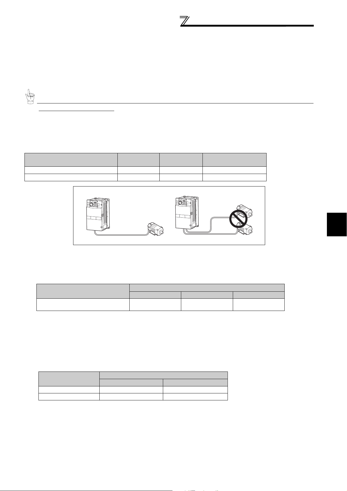
Wiring
(2) Notes on earthing (grounding)
• Leakage currents flow in the inverter. To prevent an electric shock, the inverter and motor must be earthed (grounded). This
inverter must be earthed (grounded). Earthing (Grounding) must conform to the requirements of national and local safety
regulations and electrical codes. (NEC section 250, IEC 536 class 1 and other applicable standards)
A neutral-point earthed (grounded) power supply for 400V class inverter in compliance with EN standard must be used.
• Use the dedicated earth (ground) terminal to earth (ground) the inverter.
(Do not use the screw in the casing, chassis, etc.)
• Use the thickest possible
and minimize the cable length. The earthing (grounding) point should be as near as possible to the inverter.
15
To be compliant with the EU Directive (Low Voltage Directive), earth (ground) the inverter according to
the instructions on page 171.
(3) Total wiring length
Under general-purpose motor control
Connect one or more general-purpose motors within the total wiring length shown in the following table.
earth (ground)
cable. Use the cable whose size is equal to or greater than that indicated in
page
Pr. 72 PWM frequency selection Setting
(carrier frequency)
2 (2kHz) or lower 300m 500m 500m
3 (3kHz) or higher 200m 300m 500m
Total wiring length when using a general-purpose motor (2.2K or higher)
0.75K 1.5K 2.2K or Higher
300m
500m or less
300m + 300m = 600m
300m
When driving a 400V class motor by the inverter, surge voltages attributable to the wiring constants may occur at the
motor terminals, deteriorating the insulation of the motor. Take the following measures 1) or 2) in this case.
1) Use a "400V class inverter-driven insulation-enhanced motor" and set frequency in Pr. 72 PWM frequency selection
according to wiring length.
Wiring Length
50m or less 50m to 100m exceeding 100m
Pr. 72 PWM frequency selection Setting
(carrier frequency)
14.5kHz or lower 9kHz or lower 4kHz or lower
2) Connect the surge voltage suppression filter (FR-ASF-H/FR-BMF-H) to the 55K or lower and the sine wave filter
(MT-BSL/BSC) to the 75K or higher on the inverter output side.
Under IPM motor control
Connect an IPM motor within the total wiring length of 100m.
Use one dedicated IPM motor for one inverter. Multiple IPM motors cannot be connected to an inverter.
To drive a 400V-class motor with an inverter under IPM control, set Pr.72 PWM frequency selection according to the wiring
length as shown below.
Applied inverter
FR-F740P-0.75K to 1.5K 0(2kHz) to 15(14kHz) 5(2kHz) or lower
Other 0(2kHz) to 15(14kHz) 9(6kHz) or lower
50m or less 50m to 100m
Wiring Length
2
INSTALLATION AND WIRING
17
Page 25
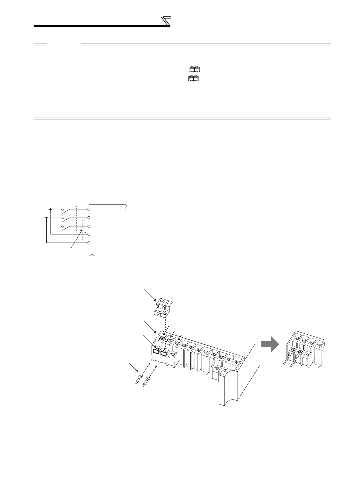
Wiring
CAUTION
· Especially for long-distance wiring, the inverter may be affected by a charging current caused by the stray capacitances of the
wiring, leading to a malfunction of the overcurrent protective function or fast response current limit function or a malfunction or fault
of the equipment connected on the inverter output side. If fast-response current limit function malfunctions, disable this function.
(For Pr.156 Stall prevention operation selection, refer to Chapter 4 of the Instruction Manual (Applied).)
· For details of Pr. 72 PWM frequency selection , refer to Chapter 4 of the Instruction Manual (Applied). (When using an optional
sine wave filter (MT-BSL/BSC) for the 75K or higher, set "25" in Pr.72 (2.5kHz).
purpose motor.)
· The surge voltage suppression filter (FR-ASF-H/FR-BMF-H) option and sine wave filter (MT-BSL/BSC) cannot be used under
IPM motor control, so do not connect them.
· For explanation of surge voltage suppression filter (FR-ASF-H/FR-BMF-H) and sine wave filter (MT-BSL/BSC), refer to the
manual of each option.
(4) Cable size of the control circuit power supply (terminal R1/L11, S1/L21)
· Terminal Screw Size: M4
· Cable size: 0.75mm
· Tightening torque: 1.5N·m
2
to 2mm
2
(5) When connecting the control circuit and the main circuit separately to the power supply
(Sine wave filter can be only used with a general-
<Connection diagram> When fault occurs, opening of the electromagnetic contactor (MC) on the
MC
Remove the jumper
R/L1
S/L2
T/L3
R1/L11
S1/L21
Inverter
inverter power supply side results in power loss in the control circuit,
disabling the fault output signal retention. Terminals R1/L11 and S1/L21 are
provided for when retention of a fault signal is required. In this case, connect
the power supply terminals R1/L11 and S1/L21 of the control circuit to the
primary side of the MC.
Do not connect the power cable to incorrect terminals. Doing so may
damage the inverter.
• FR-F720P-0.75K to 5.5K, FR-F740P-0.75K to 5.5K
1)Loosen the upper screws.
2)Remove the lower screws.
3)Remove the jumper
4)Connect the separate power
supply cable for the control
circuit to the lower terminals
(R1/L11, S1/L21).
3)
1)
2)
4)
R1/L11
R/L1
S1/L21
S/L2
T/L3
R1/L11
S1/L21
18
Main circuit terminal block
Page 26
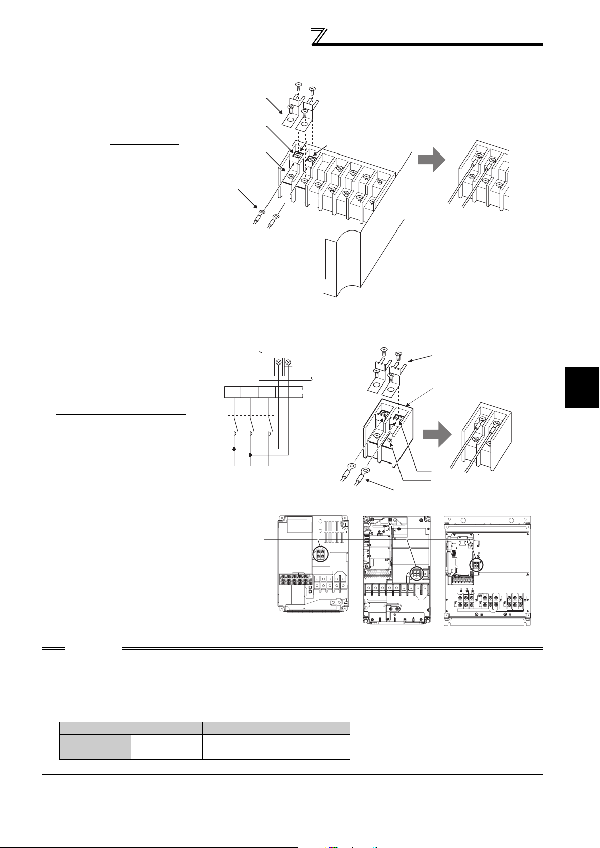
• FR-F720P-7.5K, 11K, FR-F740P-7.5K, 11K
1)Remove the upper screws.
2)Remove the lower screws.
3)Remove the jumper.
4)Connect the separate power
supply cable for the control
circuit to the upper terminals
(R1/L11, S1/L21).
Wiring
3)
1)
R1/L11
2)
S1/L21
R1/L11
S1/L21
4)
• FR-F720P-15K, FR-F740P-15K or higher
1)Remove the upper screws.
2)Remove the lower screws.
3)Pull the jumper toward you to
remove.
Connect the separate power supply
4)
cable for the control circuit to the
upper terminals (R1/L11, S1/L21)
.
S/L2
R/L1
MC
Main power supply
R/
S/
L1
L2
Main circuit
terminal block
R1/
S1/
L11
L21
Power supply
terminal block
for the control circuit
T/L3
FR-F720P-15K
FR-F740P-15K, 18.5K
T/
L3
3)
Power supply terminal block
FR-F720P-18.5K to 30K
FR-F740P-22K, 30K
for the control circuit
R1/L11
1)
2)
4)
FR-F720P-37K or higher
FR-F740P-37K or higher
S1/L21
2
Power supply
terminal block for
the control circuit
VUW
CAUTION
· Be sure to use the inverter with the jumpers across terminals R/L1 and R1/L11, and S/L2 and S1/L21 removed when supplying
power from other sources. The inverter may be damaged if you do not remove the jumper.
· The voltage should be the same as that of the main control circuit when the control circuit power is supplied from other than the
primary side of the MC.
· The power capacity necessary when separate power is supplied from R1/L11 and S1/L21 differs according to the inverter
capacity.
15K or lower 18.5K 22K or higher
200V class 60VA 80VA 80VA
400V class 60VA 60VA 80VA
· If the main circuit power is switched OFF (for 0.1s or more) then ON again, the inverter resets and a fault output will not be held.
INSTALLATION AND WIRING
19
Page 27
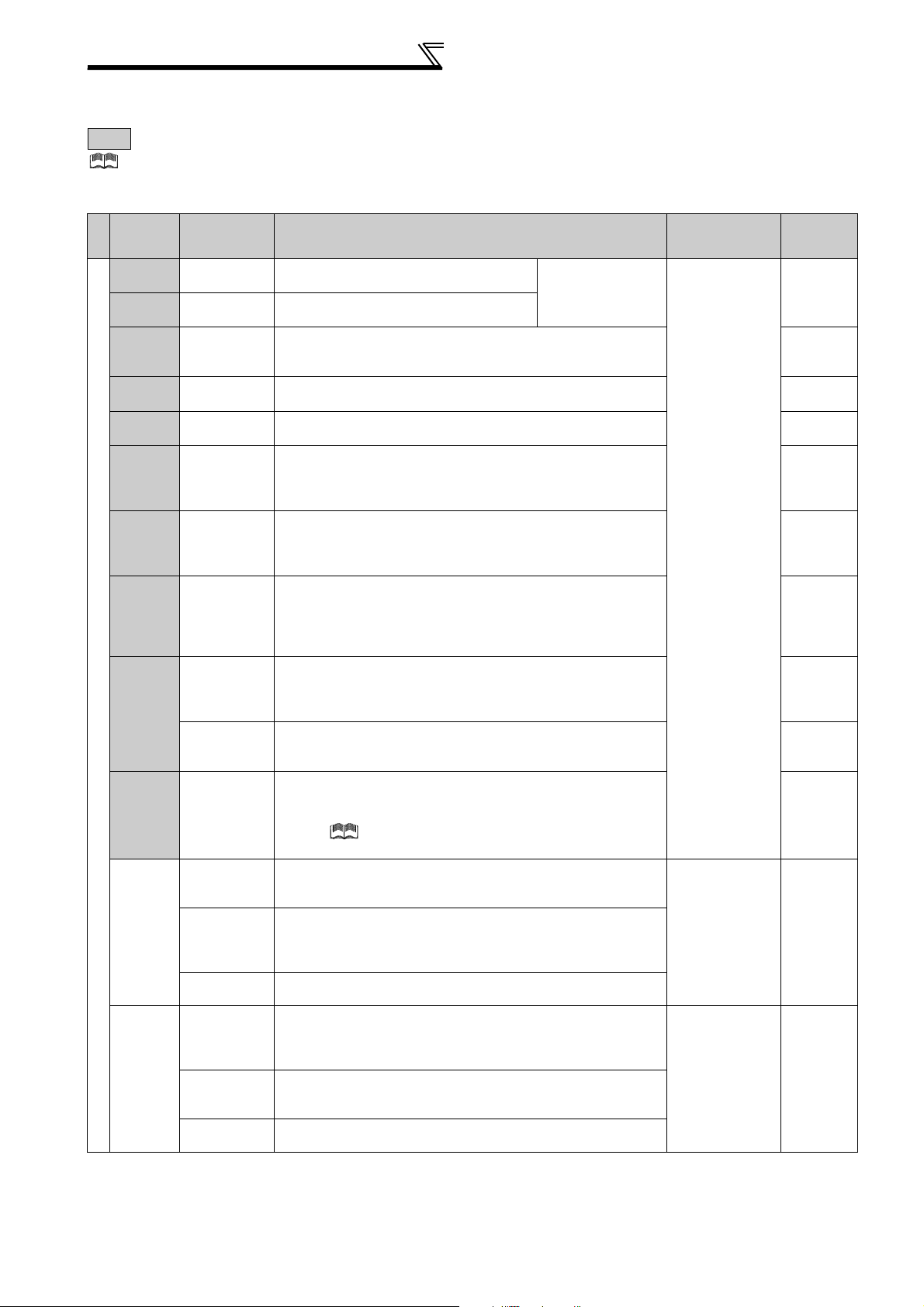
Wiring
2.4.5 Control circuit terminals
indicates that terminal functions can be selected using Pr. 178 to Pr. 196 (I/O terminal function selection) (Refer to Chapter 4 of
the Instruction Manual (Applied).)
(1) Input signals
Terminal
Symbol
Type
STF
STR
STOP
RH,
RM, RL
JOG
RT
MRS Output stop
RES Reset
AU
Contact input
CS
SD
PC
Ter min al
Name
Forward
rotation start
Reverse
rotation start
Start selfholding
selection
Multi-speed
selection
Jog mode
selection
Second
function
selection
Terminal 4
input selection
PTC input
Selection of
automatic
restart after
instantaneous
power failure
Contact input
common (sink)
(initial setting)
External
transistor
common
(source)
24VDC power
supply common
External
transistor
common (sink)
(initial setting)
Contact input
common
(source)
24VDC power
supply
Description
Turn ON the STF signal to start forward
rotation and turn it OFF to stop.
Turn ON the STR signal to start reverse
rotation and turn it OFF to stop.
Turn ON the STOP signal to self-hold the start signal. *2
Multi-speed can be selected according to the combination of RH,
RM and RL signals.
Turn ON the JOG signal to select Jog operation (initial setting)
and turn ON the start signal (STF or STR) to start Jog operation.
Turn ON the RT signal to select second function.
When the second function such as "second torque boost" and
"second V/F (base frequency)" are set, turning ON the RT signal
selects these functions.
Turn ON the MRS signal (20ms or more) to stop the inverter
output.
Use to shut off the inverter output when stopping the motor by
electromagnetic brake.
Use to reset fault output provided when fault occurs.
Turn ON the RES signal for more than 0.1s, then turn it OFF.
In the initial status, reset is set always-enabled. By setting Pr.75,
reset can be set enabled only at fault occurrence. Inverter
recovers about 1s after the reset is released.
Terminal 4 is valid only when the AU signal is turned ON. (The
frequency setting signal can be set between 0 and 20mADC.)
Turning the AU signal ON makes terminal 2 (voltage input)
invalid.
AU terminal is used as PTC input terminal (thermal protection of
the motor). When using it as PTC input terminal, set the AU/PTC
switch to PTC.
When the CS signal is left
power restoration. Note that restart setting is necessary for this
operation. In the initial setting, a restart is disabled.
(Refer to Pr. 57 Restart coasting time in Chapter 4 of the Instruction
Manual (Applied).)
Common terminal for contact input terminal (sink logic) and terminal
FM.
Connect this terminal to the power supply common terminal of a
transistor output (open collector output) device, such as a
programmable controller, in the source logic to avoid malfunction by
undesirable currents.
Common output terminal for 24VDC 0.1A power supply (PC terminal).
Isolated from terminals 5 and SE.
Connect this terminal to the power supply common terminal of a
transistor output (open collector output) device, such as a
programmable controller, in the sink logic to avoid malfunction by
undesirable currents.
Common terminal for contact input terminal (source logic).
Can be used as 24VDC 0.1A power supply.
ON
, the inverter restarts automatically at
When the STF and
STR signals are turned
ON simultaneously, the
stop command is given.
Rated
Specifications
Input resistance
4.7kΩ
Voltage at
opening: 21 to
27VDC
Contacts at
short-circuited: 4
to 6mADC
-------------------- —
Power supply
voltage range
19.2 to 28.8VDC
Permissible load
current 100mA
Refer to
Page
61
65
*2
*2
*2
116
69
*2
*2
24
20
Page 28
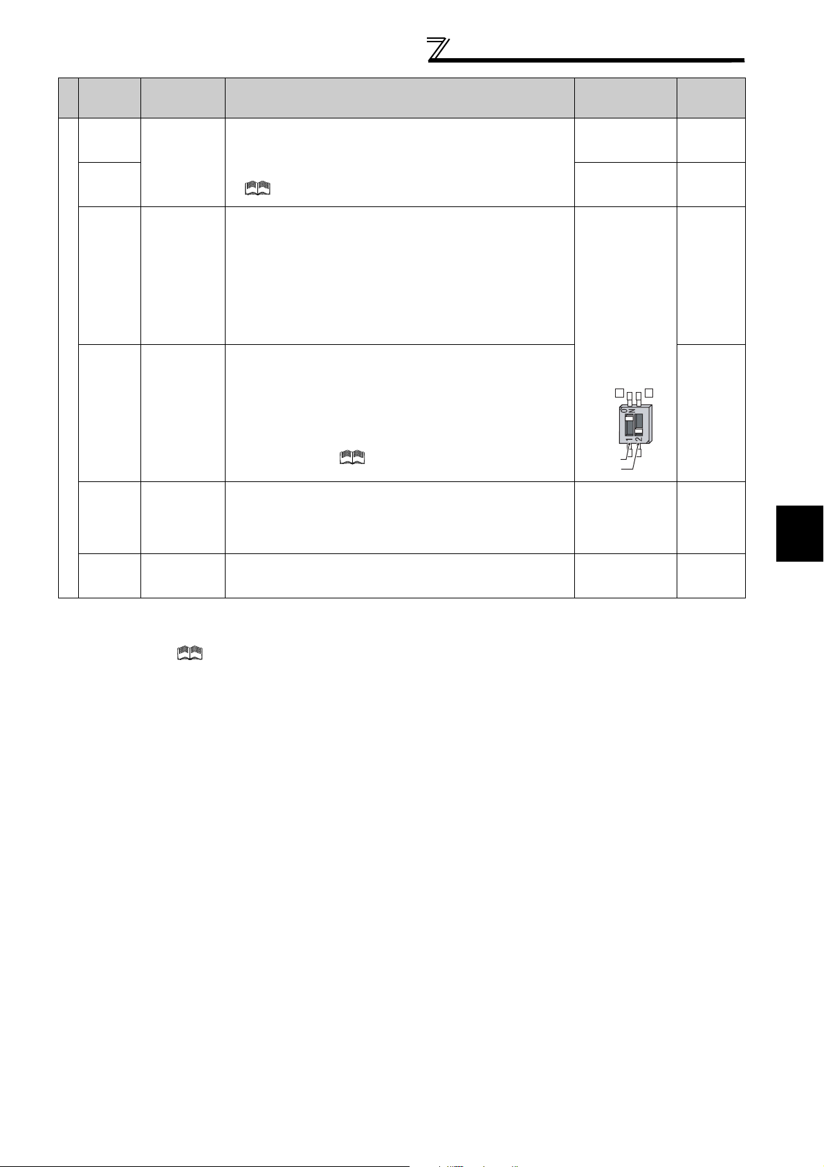
Wiring
Terminal
Symbol
Type
10E
10
Terminal
Name
Frequency
setting power
supply
Description
When connecting the frequency setting potentiometer at an initial
status, connect it to terminal 10.
Change the input specifications of terminal 2 when connecting it
to terminal 10E. (Refer to Pr. 73 Analog input selection in Chapter 4
of the Instruction Manual (Applied).)
Rated
Specifications
10VDC
Permissible load
current 10mA
5VDC
Permissible load
current 10mA
Voltage input:
Input resistance
Inputting 0 to 5VDC (or 0 to 10V, 0 to 20mA) provides the
2
setting
(voltage)
Frequency
maximum output frequency at 5V (10V, 20mA) and makes input
and output proportional. Use Pr. 73 to switch from among input 0
to 5VDC (initial setting), 0 to 10VDC, and 0 to 20mA.
Set the voltage/current input switch in the ON position to select
current input (0 to 20mA).
*1
10kΩ ± 1kΩ
Maximum
permissible
voltage 20VDC
Current input:
Input resistance
245Ω ± 5Ω
Maximum
permissible
current 30mA
Inputting 4 to 20mADC (or 0 to 5V, 0 to 10V) provides the
maximum output frequency at 20mA (5V, 10V) makes input and
Frequency setting
4
Frequency
setting
(current)
output proportional. This input signal is valid only when the AU
signal is ON (terminal 2 input is invalid). Use Pr. 267 to switch
from among input 4 to 20mA (initial setting), 0 to 5VDC, and 0 to
10VDC. Set the voltage/current input switch in the OFF position
to select voltage input (0 to 5V/0 to 10V).
*1
(Refer to Chapter 4 of the Instruction Manual (Applied).)
Voltage/current
input switch
Switch 1
Switch 2
2
4
Input resistance
Frequency
1
setting
auxiliary
Inputting 0 to ±5 VDC or 0 to ±10VDC adds this signal to terminal
2 or 4 frequency setting signal. Use Pr.73 to switch between the
input 0 to ±5VDC and 0 to ±10VDC (initial setting).
10kΩ ± 1kΩ
Maximum
permissible voltage
± 20VDC
Frequency
5
setting
common
*1 Set Pr. 73, Pr. 267, and a voltage/current input switch correctly, then input an analog signal in accordance with the setting.
Applying a voltage signal with voltage/current input switch ON (current input is selected) or a current signal with switch OFF (voltage input is
selected) could cause component damage of the inverter or analog circuit of signal output devices.
*2 Refer to Chapter 4 of the Instruction Manual (Applied).
Common terminal for frequency setting signal (terminal 2, 1 or 4)
and analog output terminal AM. Do not earth (ground).
-------------------- ------
Refer to
Page
*2
59, 67
59, 67
60, 69
*2
2
21
INSTALLATION AND WIRING
Page 29
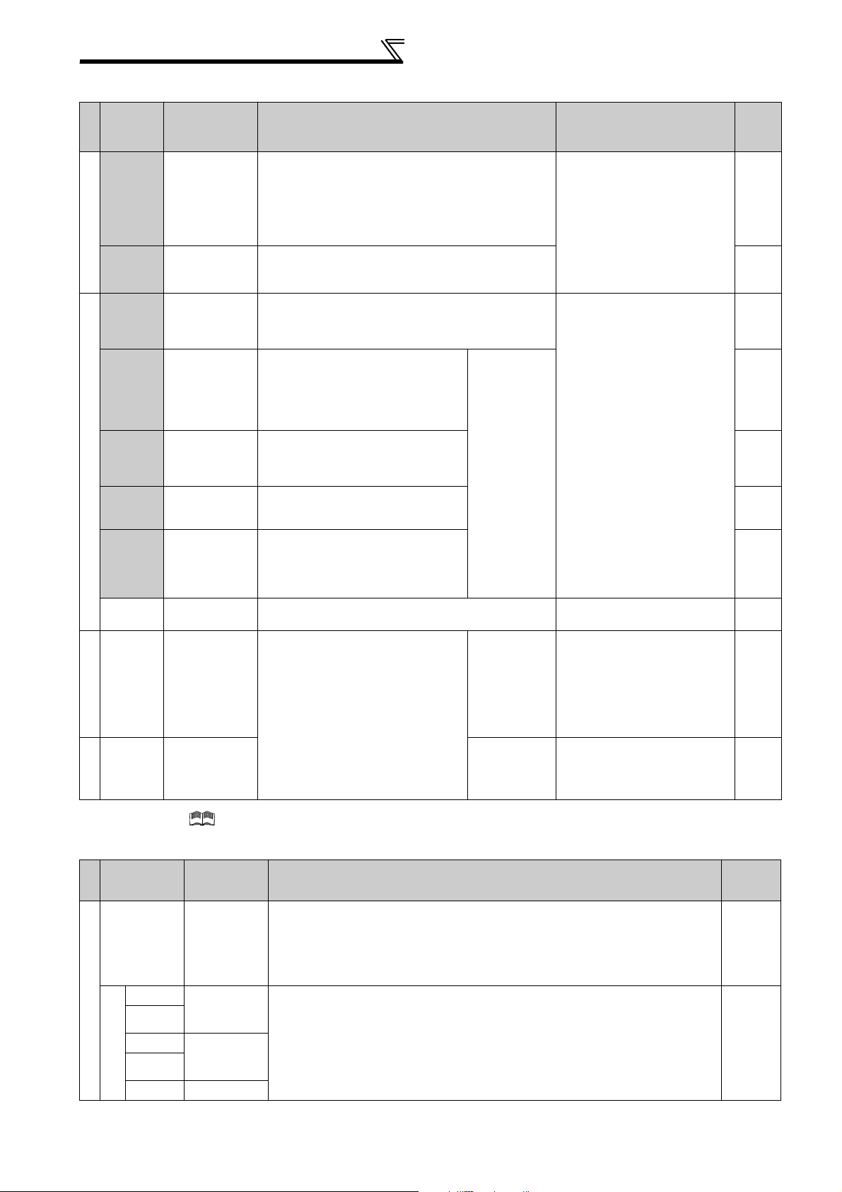
Wiring
(2) Output signals
Terminal
Symbol
Type
A1,
B1,
C1
Relay
A2,
B2,
C2
RUN
SU
OL
Open collector
IPF
FU
SE
FM For meter
Pulse
AM
Analog
Relay output 1
(Fault output)
Relay output 2 1 changeover contact output *
Inverter
running
Up to
frequency
Overload
warning
Instantaneous
power failure
Frequency
detection
Open collector
output common
Analog signal
output
Terminal
Name
Refer
Description Rated Specifications
Page
1 changeover contact output indicates that the
inverter’s protective function has activated and the
output stopped.
Fault: No conduction between B and C (conduction
between A and C)
Normal: Conduction between B and C (No conduction
between A and C)
Switched low when the inverter output frequency is
equal to or higher than the starting frequency (initial
value 0.5Hz). Switched high during stop or DC
injection brake operation.
Switched low when the output
frequency reaches within the range
of ±10% (initial value) of the set
frequency. Switched high during
acceleration/deceleration and at a
stop.
Switched low when stall prevention is
activated by the stall prevention
function. Switched high when stall
prevention is cancelled.
Switched low when an instantaneous
power failure and under voltage
protections are activated.
Switched low when the inverter
output frequency is equal to or higher
than the preset detected frequency
and high when less than the preset
detected frequency.
C o m m o n t e r m i n a l f o r t e r m i n a l s R U N , S U , O L , I P F , F U -------------------- -----
Select one e.g. output frequency
from monitor items. (Not output
during inverter reset.)
The output signal is proportional to
the magnitude of the corresponding
monitoring item.
To set a full-scale value for
monitoring the output frequency and
the output current, set Pr.56 and
Pr.158.
Alarm code
(4bit) output
Output item:
Output
frequency
(initial setting)
Output item:
Output
frequency
(initial setting)
Contact capacity: 230VAC 0.3A
(Power factor=0.4)
30VDC 0.3A
Permissible load 24VDC
(27VDC maximum) 0.1A
(A voltage drop is 3.4V
maximum when the signal is
ON.)
Low is when the open collector
output transistor is ON
(conducts).
High is when the transistor is
OFF (does not conduct).
Permissible load current 2mA
1440 pulse/s at 60Hz (generalpurpose motor control)
1440 pulse/s at 90Hz (IPM motor
control with 30K or lower)
1440 pulse/s at 120Hz (IPM
motor control with 37K or higher)
Output signal 0 to 10VDC
Permissible load current 1mA
(load impedance 10kΩ or
more) Resolution 8 bit
to
*
*
*
*
*
*
*
*
* Refer to Chapter 4 of the Instruction Manual (Applied).
(3) Communication
Terminal
Symbol
Typ e
RS-485
RS-485 terminals
—
TXD+
TXD-
RXD+
RXD-
SG
Terminal
Name
PU
connector
Inverter
transmission
terminal
Inverter
reception
terminal
Earth (Ground)
With the PU connector, communication can be established through RS-485.
(for connection on a 1:1 basis only)
Conforming standard : EIA-485 (RS-485)
Transmission format : Multidrop link
Communication speed : 4800 to 38400bps
Overall length : 500m
With the RS-485 terminals, communication can be established through RS-485.
Conforming standard : EIA-485 (RS-485)
Transmission format : Multidrop link
Communication speed : 300 to 38400bps
Overall length : 500m
22
Description
Refer to
Page
26
27
Page 30
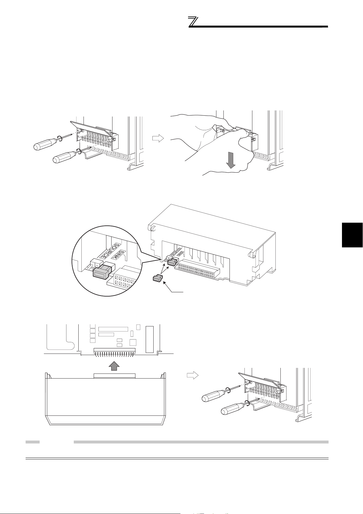
Wiring
2.4.6 Changing the control logic
The input signals are set to sink logic (SINK) when shipped from the factory.
To change the control logic, the jumper connector on the back of the control circuit terminal block must be moved to the
other position.
(The output signals may be used in either the sink or source logic independently of the jumper connector position.)
1)Loosen the two installation screws in both ends of the control circuit terminal block. (These screws cannot be
removed.)
Pull down the terminal block from behind the control circuit terminals.
2)Change the jumper connector set to the sink logic (SINK) on the rear panel of the control circuit terminal block to
source logic (SOURCE).
Jumper connector
3)Using care not to bend the pins of the inverter's control circuit connector, reinstall the control circuit terminal block
and fix it with the mounting screws.
2
INSTALLATION AND WIRING
CAUTION
1. Make sure that the control circuit connector is fitted correctly.
2. While power is on, never disconnect the control circuit terminal block.
23
Page 31

Wiring
r
4)Sink logic and source logic
⋅ In sink logic, a signal switches ON when a current flows from the corresponding signal input terminal.
Terminal SD is common to the contact input signals. Terminal SE is common to the open collector output signals.
⋅ In source logic, a signal switches ON when a current flows into the corresponding signal input terminal.
Terminal PC is common to the contact input signals. Terminal SE is common to the open collector output signals.
Current flow concerning the input/output signal
when sink logic is selected
Sink logic
Current
STF
STR
SD
Inverter
RUN
SE
R
R
24VDC
TB1
-
+
TB17
Current flow
DC input (sink type)
<Example: QX40>
R
R
Sink
connector
Current flow concerning the input/output signal
when source logic is selected
Source logic
PC
Current
STF
R
STR
R
Inverter
RUN
SE
+
24VDC
Current flow
DC input (source type)
<Example: QX80>
TB1
R
-
TB18
Source
connecto
R
• When using an external power supply for transistor output
⋅ Sink logic type
Use terminal PC as a common terminal, and perform
wiring as shown below. (Do not connect terminal SD of
the inverter with terminal 0V of the external power
supply. When using terminals PC and SD as a 24VDC
power supply, do not install a power supply in parallel in
the outside of the inverter. Doing so may cause a
malfunction due to undesirable current.)
QY40P type transistor
output unit
Constant
voltage
circuit
TB1
TB2
TB17
TB18
STF
STR
24VDC
Inverter
24VDC
(SD)
PC
SD
Current flow
⋅ Source logic type
Use terminal SD as a common terminal, and perform
wiring as shown below. (Do not connect terminal PC of
the inverter with terminal +24V of the external power
supply. When using terminals PC and SD as a 24VDC
power supply, do not install an external power supply in
parallel with the inverter. Doing so may cause a
malfunction in the inverter due to undesirable currents.)
QY80 type transistor
output unit
Constant
voltage
circuit
Fuse
TB1
TB2
TB17
TB18
Current flow
PC
STF
STR
24VDC
SD
Inverter
24VDC
(SD)
24
Page 32

2.4.7 Wiring of control circuit
(1) Control circuit terminal layout
Wiring
A1 B1 C1 A2
RUN
SE
OLIPFSU
B2 C2
AURTRHRMRL
10E
10
STOP
RES
MRS
STF
SDSDFU PCCS
254
SD
JOG
STR
Terminal screw size: M3.5
Tightening torque: 1.2N·m
1
AMFM
(2) Common terminals of the control circuit (SD 5, SE)
Control circuit terminal
Terminals SD, 5, and SE are all common terminals (0V) for I/O signals and are isolated from each other. Do not
earth(ground) these terminals.
Avoid connecting the terminal SD and 5 and the terminal SE and 5.
Terminal SD is a common terminal for the contact input terminals (STF, STR, STOP, RH, RM, RL, JOG, RT, MRS, RES,
AU, CS) and frequency output signal (FM).
The open collector circuit is isolated from the internal control circuit by photocoupler.
Terminal 5 is a common terminal for frequency setting signal (terminal 2, 1 or 4) and analog output terminal AM.
It should be protected from external noise using a shielded or twisted cable.
Terminal SE is a common terminal for the open collector output terminal (RUN, SU, OL, IPF, FU).
The contact input circuit is isolated from the internal control circuit by photocoupler.
(3) Signal inputs by contactless switches
The contacted input terminals of the inverter (STF, STR, STOP,
RH, RM, RL, JOG, RT, MRS, RES, AU, CS) can be controlled
using a transistor instead of a contacted switch as shown on the
right.
External signal input using transistor
+24V
2
STF, etc
Inverter
SD
(4) Wiring instructions
1) It is recommended to use the cables of 0.75mm2 gauge for connection to the control circuit terminals.
If the cable gauge used is 1.25mm
the cables are run improperly, resulting in an operation panel contact fault.
2) The maximum wiring length should be 30m (200m for terminal FM).
3) Use two or more parallel micro-signal contacts or twin contacts to
prevent a contact faults when using contact inputs since the
control circuit input signals are micro-currents.
4) Use shielded or twisted cables for connection to the control circuit terminals and run them away from the main and
power circuits (including the 200V relay sequence circuit).
5) Do not apply a voltage to the contact input terminals (e.g. STF) of the control circuit.
6) Always apply a voltage to the fault output terminals (A, B, C) via a relay coil, lamp, etc.
2
or more, the front cover may be lifted when there are many cables running or
Micro signal contacts Twin contacts
INSTALLATION AND WIRING
25
Page 33

Wiring
Wiring of the control circuit of the 75K or higher
For wiring of the control circuit of the 75K or higher, separate away from wiring of the main circuit.
Make cuts in rubber bush of the inverter side and lead wires.
<Wiring>
Rubber bush
(view from the inside)
Make cuts along the lines inside with
a cutter knife and such.
2.4.8 Mounting the operation panel (FR-DU07) on the enclosure surface
Having an operation panel on the enclosure surface is convenient. With a connection cable, you can mount the
operation panel (FR-DU07) to the enclosure surface, and connect it to the inverter.
Use the option FR-CB2, or the following connector and cable available on the market.
Securely insert one end of connection cable into the PU connector of the inverter and the other end into the
connection connector of the operation panel (FR-DU07) along the guides until the stoppers are fixed.
Parameter unit connection cable
(FR-CB2)(option)
Operation panel(FR-DU07)
Operation panel connection connector
(FR-ADP)(option)
CAUTION
Do not connect the cable to a LAN port of a personal computer, to a fax modem socket, or to a telephone connector. Doing so may
damage the inverter and the connected device due to the differences in the electric specifications.
REMARKS
⋅ Refer to page 6 for removal method of the operation panel.
⋅ When using a commercially available connector and cable as a parameter unit connection cable, refer to Chapter 2 of the
Instruction Manual (Applied).
⋅ The inverter can be connected to the computer and FR-PU04/FR-PU07.
26
Page 34

2.4.9 RS-485 terminal block
⋅ Conforming standard: EIA-485(RS-485)
⋅ Transmission format: Multidrop link
⋅ Communication speed: MAX 38400bps
⋅ Overall length: 500m
⋅ Connection cable:Twisted pair cable
(4 pairs)
OPEN
100Ω
TXD
RDA1
(RXD1+)
(RXD1-)
SDA1
(TXD1+)
Terminating resistor switch
Factory-set to "OPEN".
Set only the terminating resistor switch of
the remotest inverter to the "100Ω" position.
RDB1
RDA2
RDB2
SDB2
(TXD2-)
RXD
(RXD2+)
SDB1
(TXD1-)
(RXD2-)
SDA2
(TXD2+)
Wiring
2.4.10 Communication operation
Using the PU connector or RS-485 terminal, you can
perform communication operation from a personal
computer etc. When the PU connector is connected
with a personal, FA or other computer by a
communication cable, a user program can run and
monitor the inverter or read and write to parameters.
For the Mitsubishi inverter protocol (computer link
operation), communication can be performed with the
PU connector and RS-485 terminal.
For the Modbus-RTU protocol, communication can be
performed with the RS-485 terminal.
For further details,
Instruction Manual (Applied).
refer to Chapter 4 of the
P5S
(VCC)SG(GND)
Programmable controller
P5S
(VCC)SG(GND)
Inverter Inverter Inverter
VCC
2
Multidrop link
(32 inverters
maximum are
connectable)
INSTALLATION AND WIRING
27
Page 35

Connection of stand-alone option units
r
2.5 Connection of stand-alone option units
The inverter accepts a variety of stand-alone option units as required.
Incorrect connection will cause inverter damage or accident. Connect and operate the option unit carefully in
accordance with the corresponding option unit manual.
2.5.1 Connection of the brake unit (FR-BU2)
Connect the brake unit (FR-BU2) as shown below to improve the braking capability at deceleration.
(1) Connection example with the GRZG type discharging resistor
OCR contact
OFFON
*2
Three-phase AC
power supply
MCCB
MC
R/L1
S/L2
T/L3
Inverter
T
MC
U
V
Motor
M
OCR
External thermal
relay
W
*3
P/+
N/-
*1
10m or less
*3
MC
GRZG type
discharging resistor
RR
*4
FR-BU2
PR
P/+
N/-
A
B
C
BUE
SD
*5
*1 Connect the inverter terminals (P/+, N/-) and brake unit (FR-BU2) terminals so that their terminal names match with each other.
(Incorrect connection will damage the inverter and brake unit.)
*2 When the power supply is 400V class, install a step-down transformer.
*3 Keep a wiring distance of within 5m between the inverter, brake unit (FR-BU2) and discharging resistor. Even when the wiring
is twisted, the cable length must not exceed 10m. When twisting, twist at least 5 times per meter.
The brake unit may be damaged if cables are not twisted when the wiring length is 5m or more or the wiring length exceeds
10m or more even if cables are twisted.
*4 It is recommended to install an external thermal relay to prevent overheat of discharging resistors.
Refer to FR-BU2 manual for connection method of discharging resistor.
*5
<Recommended external thermal relay>
Brake Unit Discharging Resistor Recommended External Thermal Relay
FR-BU2-1.5K
FR-BU2-3.7K
FR-BU2-7.5K
FR-BU2-15K
FR-BU2-H7.5K
FR-BU2-H15K
FR-BU2-H30K
GZG 300W-50Ω (one)
GRZG 200-10Ω (three in series)
GRZG 300-5Ω (four in series)
GRZG 400-2Ω (six in series)
GRZG 200-10Ω (six in series)
GRZG 300-5Ω (eight in series)
GRZG 400-2Ω (twelve in series)
TH-N20CXHZ 1.3A
TH-N20CXHZ 3.6A
TH-N20CXHZ 6.6A
TH-N20CXHZ 11A
TH-N20CXHZ 3.6A
TH-N20CXHZ 6.6A
TH-N20CXHZ 11A
CAUTION
⋅ Set "1" in Pr. 0 Brake mode selection of the FR-BU2 to use GRZG type discharging resistor.
⋅ Do not remove a jumper across terminal P/+ and P1 except when connecting a DC reactor.
1/L1 5/L3
2/T1 6/T3
To the brake
unit terminal P/+
TH-N20
To a resisto
28
Page 36

(2) FR-BR-(H) connection example with resistor unit
*2
T
Connection of stand-alone option units
OFFON
MC
MC
MCCB
Three phase AC
power supply
MC
R/L1
S/L2
T/L3
U
V
W
Motor
M
*3
Inverter
P/+
N/-
*1 Connect the inverter terminals (P/+, N/-) and brake unit (FR-BU2) terminals so that their terminal names match with each other.
(Incorrect connection will damage the inverter and brake unit.)
*2 When the power supply is 400V class, install a step-down transformer.
*3 The wiring distance between the inverter, brake unit (FR-BU) and resistor unit (FR-BR) should be within 5m. Even when the
wiring is twisted, the cable length must not exceed 10m.
*4 The contact between TH1 and TH2 is closed in the normal status and is open at a fault.
*1
10m or less
*3
CAUTION
⋅ Do not remove a jumper across terminal P/+ and P1 except when connecting a DC reactor.
(3) Connection example with MT-BR5 type resistor unit
After making sure that the wiring is correct, set the following parameters:
⋅ Pr. 30 Regenerative function selection = "1"
⋅ Pr. 70 Special regenerative brake duty = "0 (initial value)"
Set Pr. 0 Brake mode selection = "2" in the brake unit FR-BU2.
FR-BR
P
TH1
PR
TH2
FR-BU2
PR
P/+
N/BUE
SD
*4
A
B
C
2
*2
T
OFFON
10m
or less
CR1
MC
*3
TH1
P
PR
TH2
Resistor unit
MT-BR5
CR1
*4
MCCB
Three phase AC
power supply
*1 Connect the inverter terminals (P/+, N/-) and brake unit (FR-BU2) terminals so that their terminal names match with each other.
(Incorrect connection will damage the inverter and brake unit.)
*2 When the power supply is 400V class, install a step-down transformer.
*3 The wiring distance between the inverter, brake unit (FR-BU2) and resistor unit (MT-BR5) should be within 5m. If twisted wires
are used, the distance should be within 10m.
*4 The contact between TH1 and TH2 is open in the normal status and is closed at a fault.
*5 CN8 connector used with the MT-BU5 type brake unit is not used.
MC
R/L1
S/L2
W
T/L3
P/+
N/-
Inverter
Motor
U
V
M
*1
*3
*5
MC
P
N
PR
BUE
SD
Brake unit
FR-BU2
P
CAUTION
⋅ The stall prevention (overvoltage), oL, does not occur while Pr. 30 Regenerative function selection = "1" and Pr. 70 Special
regenerative brake duty = "0% (initial setting)."
♦ Parameters referred to ♦
Pr.30 Regenerative function selection Refer to Chapter 4 of the Instruction Manual (Applied)
Pr.70 Special regenerative brake duty Refer to Chapter 4 of the Instruction Manual (Applied)
INSTALLATION AND WIRING
29
Page 37

Connection of stand-alone option units
2.5.2 Connection of the brake unit (FR-BU/MT-BU5)
When connecting the brake unit (FR-BU(H)/MT-BU5) to improve the brake capability at deceleration, make connection
as shown below.
(1) Connection with the FR-BU (55K or lower)
OFFON
T *2
MC
MCCB
Three-phase AC
power supply
*1 Connect the inverter terminals (P/+, N/-) and brake unit (FR-BU (H)) terminals so that their terminal signals match
with each other. (Incorrect connection will damage the inverter.)
*2 When the power supply is 400V class, install a step-down transformer.
*3 The wiring distance between the inverter, brake unit (FR-BU) and resistor unit (FR-BR) should be within 5m. If
twisted wires are used, the distance should be within 10m.
MC
R/L1
S/L2
T/L3
Inverter
U
V
W
P/+
N/−
MC
Motor
M
*1
*3
10m or less
FR-BR
P
PR
FR-BU
PR
P/+
N/−
TH1
TH2
HA
HB
HC
CAUTION
⋅ If the transistors in the brake unit should become faulty, the resistor can be unusually hot, causing a fire. Therefore, install a
magnetic contactor on the inverter’s input side to configure a circuit so that a current is shut off in case of fault.
⋅ Do not remove a jumper across terminal P/+ and P1 except when connecting a DC reactor.
30
Page 38

Connection of stand-alone option units
A
(2) Connection with the MT-BU5 (75K or higher)
After making sure that the wiring is correct, set the following parameters:
⋅ Pr. 30 Regenerative function selection = "1"
⋅ Pr. 70 Special regenerative brake duty = "10%"
T *1
OFFON
MCCB
Three-phase
C power
supply
*1 When the power supply is 400V class, install a step-down transformer.
*2 The wiring length between the resistor unit and brake resistor should be 10m maximum when wires are
twisted and 5m maximum when wires are not twisted.
MC
R/L1
S/L2
T/L3
Inverter
CN8
P/+
N/
U
V
W
Motor
M
P
PR
P
PR
Brake unit
MT-BU5
MC
10m or
less
*2
CAUTION
⋅ Install the brake unit in a place where a cooling air reaches the brake unit heatsink and within a distance of the cable supplied
with the brake unit reaches the inverter.
⋅ For wiring of the brake unit and inverter, use an accessory cable supplied with the brake unit. Connect the main circuit cable to
the inverter terminals P/+ and N/- and connect the control circuit cable to the CN8 connector inside by making cuts in the
rubber bush at the top of the inverter for leading the cable.
⋅ The brake unit which uses multiple resistor units has terminals equal to the number of resistor units. Connect one resistor unit
to one pair of terminal (P, PR).
<Inserting the CN8 connector>
Make cuts in rubber bush of the upper portion of the inverter and lead a cable.
1) Make cuts in the rubber bush for leading the CN8 connector cable with a nipper or cutter knife.
CR1 CR2
P
PR
P
PR
Resistor unit
MT-BR5
TH1
TH2
TH1
TH2
MC
CR1
CR2
2
Rubber bushes
Make cuts in
rubber bush
INSTALLATION AND WIRING
2) Insert a connector on the MT-BU5 side through a rubber bush to connect to a connector on the inverter side.
CN8 connector
Wire clamp
CAUTION
Clamp the CN8 connector cable on the inverter side with a wire clamp securely.
♦ Parameters referred to ♦
Pr.30 Regenerative function selection Refer to Chapter 4 of the Instruction Manual (Applied)
Pr.70 Special regenerative brake duty Refer to Chapter 4 of the Instruction Manual (Applied)
Insert the connector until
you hear a click sound.
31
Page 39

Connection of stand-alone option units
A
A
r
2.5.3 Connection of the brake unit (BU type)
Connect the brake unit (BU type) correctly as shown below. Incorrect connection will damage the inverter. Remove the jumper
across terminals HB and PC and terminals TB and HC of the brake unit and fit it to across terminals PC and TB.
OFFON
T*1
MC
Three-phase
C power
supply
MCCB
MC
R/L1
S/L2
T/L3
Inverter
N/-
P/+
Motor
U
V
M
W
MC
Brake unit
N
(BU type)
OCR
Remove the
jumper
TB
HC
HB
Discharging
resistor
OCR
PR
HA
PC
Fit a jumper
P
*1 When the power supply is 400V class, install a step-down transformer.
CAUTION
⋅ The wiring distance between the inverter, brake unit and discharging resistor should be within 2m. If twisted wires are used, the
distance should be within 5m.
⋅ If the transistors in the brake unit should become faulty, the resistor can be unusually hot, causing a fire. Therefore, install a
magnetic contactor on the inverter's power supply side to shut off a current in case of fault.
⋅ Do not remove a jumper across terminal P/+ and P1 except when connecting a DC reactor.
2.5.4 Connection of the high power factor converter (FR-HC/MT-HC)
When connecting the high power factor converter (FR-HC/MT-HC) to suppress power harmonics, perform wiring securely as
shown below. Incorrect connection will damage the high power factor converter and inverter.
After making sure that the wiring is correct, set "2" in Pr. 30 Regenerative function selection. (Refer to Chapter 4 of the Instruction
Manual (Applied).)
(1) Connection with the FR-HC (55K or lower)
High power factor converter
Reactor2
(FR-HCL02)
R3
R4
S4
S3
T4
T3
(FR-HC)(FR-HCB)
MC1
MC2
R4
S4
T4
R
phase
S
detection
T
Y1orY2
RDY
RSO
SE
Inverter
R/L1
*1
S/L2
T/L3
P
N
P/+
*2
N/X11
*4
*3
X10
*3
RES
SD
R1/L11
S1/L21
*1
Moto
U
V
W
M
Three-phase
C power
supply
MCCB
MC
Reactor1
(FR-HCL01)
R2
R
S2
S
T
T2
Outside box
R2
S2
T2
MC1
MC2
R3
S3
T3
*1 Remove the jumpers across the inverter terminals R/L1 and R1/L11 and terminals S/L2 and S1/L21, and connect the control circuit power supply
to the R1/L11 and S1/L21 terminals. Do not connect anything to the power input terminals R/L1, S/L2, and T/L3. Incorrect connection will damage
the inverter. (E.OPT (option fault) will occur. (Refer to page 127.))
*2 Do not insert the MCCB between terminals P/+ and N/- (P/+ and P/+, N/- and N/-). Opposite polarity of terminals N/-, P/+ will damage the inverter.
*3 Use Pr. 178 to Pr. 189 (input terminal function selection) to assign the terminals used for the X10 (X11) signal. (Refer to Chapter 4 of the Instruction
Manual (Applied).)
For communication where the start command is sent only once, e.g. RS-485 communication operation, use the X11 signal when making setting to
hold the mode at occurrence of an instantaneous power failure. (Refer to Chapter 4 of the Instruction Manual (Applied).)
*4 Be sure to connect terminal RDY of the FR-HC to the X10 signal or MRS signal assigned terminal of the inverter, and connect terminal SE of the
FR-HC to terminal SD of the inverter. Without proper connecting, FR-HC will be damaged.
CAUTION
⋅ The voltage phases of terminals R/L1, S/L2, T/L3 and terminals R4, S4, T4 must be matched.
⋅ Use sink logic (initial setting) when the FR-HC is connected. The FR-HC cannot be connected when source logic is selected.
⋅ Do not connect a DC reactor to the inverter when FR-HC is connected.
⋅ Do not remove a jumper across terminal P/+ and P1.
32
Page 40

(2) Connection with the MT-HC (75K or higher)
A
Connection of stand-alone option units
Three-phase
C power
supply
MCCB
*1 Remove the jumper across terminals R and R1, S and S1 of the inverter, and connect the control circuit
*2 Do not insert the MCCB between terminals P/+ and N/- (P/+ and P/+, N/- and N/-). Opposite polarity of
*3 Use Pr. 178 to Pr. 189 (input terminal function selection) to assign the terminals used for the X10 (X11) signal.
*4 Connect the power supply to terminals R1 and S1 of the MT-HC via an isolated transformer.
*5 Be sure to connect terminal RDY of the MT-HC to the X10 signal or MRS signal assigned terminal of the
MC
power supply to the R1 and S1 terminals. Do not connect anything to the power input terminals R/L1, S/
L2, and T/L3. Incorrect connection will damage the inverter. (E.OPT (option fault) will occur. (Refer to page
127.)
terminals N, P will damage the inverter.
(Refer to Chapter 4 of the Instruction Manual (Applied).) For communication where the start command is sent
only once, e.g. RS-485 communication operation, use the X11 signal when making setting to hold the
mode at occurrence of an instantaneous power failure. (Refer to Chapter 4 of the Instruction Manual
(Applied).)
inverter, and connect terminal SE of the MT-HC to terminal SD of the inverter. Without proper connecting,
MT-HC will be damaged.
MT-HCL01 MT-HCB
R
R2
S
S2
T
T2
R2
S2
T2
R1 S1
MT-HCL02 MT-HC Inverter
R3
S3
T3
88R
88S
R3
S3
T3
R4
S4
T4
R4
S4
T4
88R
88S
R
S
T
P
N
RDY
RSO
SE
R1 S1
MT-HCTR
Isolated transformer
R/L1
U
*1
S/L2
V
T/L3
W
P/+
*2
N/
*5
*3
X10
RES
SD
*1
R1/
S1/
L11
L21
*4
CAUTION
⋅ The voltage phases of terminals R/L1, S/L2, T/L3 and terminals R4, S4, T4 must be matched.
⋅ Use sink logic (initial setting) when the MT-HC is connected. The MT-HC cannot be connected when source logic is
selected.
⋅ When connecting the inverter to the MT-HC, do not connect the DC reactor provided to the inverter.
Motor
M
2
♦ Parameters referred to ♦
Pr.30 Regenerative function selection Refer to Chapter 4 of the Instruction Manual (Applied)
INSTALLATION AND WIRING
33
Page 41

Connection of stand-alone option units
r
2.5.5 Connection of the power regeneration common converter (FR-CV) (55K or lower)
When connecting the power regeneration common converter (FR-CV), make connection so that the inverter terminals
(P/+, N/-) and the terminal symbols of the power regeneration common converter (FR-CV) are the same.
After making sure that the wiring is correct, set "2" in Pr. 30 Regenerative function selection.
Instruction Manual (Applied).)
(Refer to Chapter 4 of the
Three-phase
AC power
supply
*1 Remove the jumpers across terminals R/L1 and R1/L11 and terminals S/L2 and S1/L21 of the inverter,
*2 Do not insert the MCCB between the terminals P/+ and N/- (between P/L+ and P/+, between N/L- and N/-).
*3 Assign the terminal for X10 signal using any of Pr. 178 to Pr. 189 (input terminal function selection).
*4 Be sure to connect the power supply and terminals R/L11, S/L21, T/MC1.
*5 Be sure to connect terminal RDYB of the FR-CV to the X10 signal or MRS signal assigned terminal of the
R/L1
*1
S/L2
T/L3
R1/L11
*5
S1/L21
Inverter
P/+
*2
N/−
PC
SD
X10 *3
RES
Dedicated stand-alone
reactor (FR-CVL)
MCCB
and connect the control circuit power supply across terminals R1/L11 and S1/L21. Do not connect
anything to the power input terminals R/L1, S/L2, T/L3. Incorrect connection will damage the inverter.
(E.OPT (option fault) will occur. (Refer to page 127.))
Opposite polarity of terminals N/-, P/+ will damage the inverter.
(Refer to Chapter 4 of the Instruction Manual (Applied).)
Operating the inverter without connecting them will damage the power regeneration common converter.
inverter, and connect terminal SE of the FR-CV to terminal SD of the inverter. Without proper connecting,
FR-CV will be damaged.
MC1
R/L11
S/L21
T/L31
R2/L12
S2/L22
T2/L32
FR-CV type
Power regeneration
common converter
R2/L1
S2/L2
T2/L3
R/L11
S/L21
T/MC1
P/L+
N/L−
P24
*4
SD
RDYA
RDYB
RSO
SE
Moto
U
V
W
M
CAUTION
⋅ The voltage phases of terminals R/L11, S/L21, T/MC1 and terminals R2/L1, S2/L2, T2/L3 must be matched.
⋅ Use sink logic (initial setting) when the FR-CV is connected. The FR-CV cannot be connected when source logic is
selected.
⋅ Do not connect a DC reactor to the inverter when FR-CV is connected.
⋅ Do not remove a jumper across terminal P/+ and P1.
♦ Parameters referred to ♦
Pr.30 Regenerative function selection Refer to Chapter 4 of the Instruction Manual (Applied)
34
Page 42

Connection of stand-alone option units
A
2.5.6 Connection of the power regeneration converter (MT-RC) (75K or higher)
When connecting a power regeneration converter (MT-RC), perform wiring securely as shown below. Incorrect
connection will damage the regeneration converter and inverter. After connecting securely, set "1" in
Pr. 30 Regenerative function selection and "0" in Pr. 70 Special regenerative brake duty.
Three-phase
C power
supply
MCCB
MC1
MT-RCL
R
S
T
MC2
DCL
R2
S2
T2
P1
P
R/L1
S/L2
T/L3
R1/L11
S1/L21
P1
R2
S2
T2
R
S
T
R1
S1
Inverter
P/+
P
U
V
W
N/
N
RES
STF
SD
C
B
A
Motor
M
Reset signal
Alarm signal
2
RDY
Ready signal
SE
MT-RC
CAUTION
⋅
When using the FR-F700P series together with the MTRC, install a magnetic contactor (MC) at the input side of
Inverter input power supply (MC2)
ON
the inverter so that power is supplied to the inverter after
1s or more has elapsed after powering ON the MT-RC.
When power is supplied to the inverter prior to the MTRC, the inverter and the MT-RC may be damaged or the
MCCB may trip or be damaged.
⋅ Refer to the MT-RC manual for precautions for
MT-RC power supply (MC1)
ON
1s or more
INSTALLATION AND WIRING
connecting the power coordination reactor and others.
♦ Parameters referred to ♦
Pr.30 Regenerative function selection Refer to Chapter 4 of the Instruction Manual (Applied)
Pr.70 Special regenerative brake duty Refer to Chapter 4 of the Instruction Manual (Applied)
35
Page 43

Connection of stand-alone option units
2.5.7 Connection of the power factor improving DC reactor (FR-HEL)
(1) Keep the surrounding air temperature within the permissible range (-10°C to +50°C). Keep enough clearance
around the reactor because it heats up. (Take 10cm or more clearance on top and bottom and 5cm or more on left
and right regardless of the installation direction.)
10cm or more
5cm or more
5cm or more
5cm or more
5cm or more
(2) When using the DC reactor (FR-HEL), connect it between terminals P1 and P/+.
For the 55K or lower, the jumper connected across terminals P1 and P/+ must be removed. Otherwise, the reactor
will not exhibit its performance.
For the 75K or higher, a DC reactor is supplied. Always install the reactor.
P/+
P1
FR-HEL
Remove
the jumper.
CAUTION
⋅ The wiring distance should be within 5m.
The size of the cables used should be equal to or larger than that of the power supply cables (R/L1, S/L2, T/L3).
⋅
(Refer to page 15)
36
Page 44

Power-OFF and magnetic contactor
(MC)
2.6 Power-OFF and magnetic contactor (MC)
(1) Inverter input side magnetic contactor (MC)
On the inverter input side, it is recommended to provide an MC for the following purposes.
Refer to page 4 for selection.)
(
1)To release the inverter from the power supply when the fault occurs or when the drive is not functioning (e.g.
emergency stop operation).
To prevent any accident due to an automatic restart at restoration of power after an inverter stop made by a power failure
2)
3)To separate the inverter from the power supply to ensure safe maintenance and inspection work
The inverter's input side MC is used for the above purpose, select class JEM1038-AC3MC for the inverter input side
current when making an emergency stop during normal operation.
REMARKS
Since repeated inrush current at power ON will shorten the life of the converter circuit (switching life is 100 million times (about
500,000 times for the 200V class 37K or higher)), frequent starts/stops must be avoided. Turn ON/OFF the inverter start
controlling terminals (STF, STR) to run/stop the inverter.
• Inverter start/stop circuit example
As shown on the left, always use the start signal
To the
(ON or OFF of STF (STR) signal) to make a start
motor
or stop.
*1 When the power supply is 400V class, install a step-
down transformer.
*2 Connect the power supply terminals R1/L11, S1/L21
of the control circuit to the primary side of the MC to
hold an alarm signal when the inverter's protective
circuit is activated. At this time, remove jumpers
across terminals R/L1 and R1/L11, and S/L2 and S1/
L21. (Refer to page 18 for removal of the jumper.)
Power
supply
Operation preparation
OFF
Start/Stop
MC
Start
ON
MC
MCCB
MC
RA
MC
T
*1
RA
R/L1
S/L2
T/L3
R1/L11
S1/L21
Inverter
STF/STR
SD
U
V
W
*2
C1
B1
A1
2
Stop
RA
(2) Handling of the inverter output side magnetic contactor
Switch the magnetic contactor between the inverter and general-purpose motor only when both the inverter and motor
are at a stop. When the magnetic contactor is turned ON while the inverter is operating, overcurrent protection of the
inverter and such will activate. When using a magnetic contactor to switch to a commercial power supply while using a
general-purpose motor, it is recommended to use the bypass operation Pr. 135 to Pr. 139. (Refer to Chapter 4 of the
Instruction Manual (Applied)).
CAUTION
IPM motor is a synchronous motor with high-performance magnets embedded in the rotor. Motor terminals hold high-voltage while the
motor is running even after the inverter power is turned OFF. Before wiring or inspection, the motor must be confirmed to be stopped.
When the motor is driven by the load in applications such as fan and blower, a low-voltage manual contactor must be connected at the
inverter's output side, and wiring and inspection must be performed while the contactor is open. Otherwise you may get an electric shock.
INSTALLATION AND WIRING
37
Page 45

Precautions for use of the inverter
2.7 Precautions for use of the inverter
The FR-F700P series is a highly reliable product, but incorrect peripheral circuit making or operation/handling method
may shorten the product life or damage the product.
Before starting operation, always recheck the following items.
(1) Use crimping terminals with insulation sleeve to wire the power supply and motor.
(2) Application of power to the output terminals (U, V, W) of the inverter will damage the inverter. Never perform
such wiring.
(3) After wiring, wire offcuts must not be left in the inverter.
Wire offcuts can cause an alarm, failure or malfunction. Always keep the inverter clean. When drilling mounting holes in
an enclosure etc., take care not to allow chips and other foreign matter to enter the inverter.
(4) Use cables of the size to make a voltage drop 2% or less.
If the wiring distance is long between the inverter and motor, a main circuit cable voltage drop will cause the motor torque
to decrease especially at the output of a low frequency.
Refer to page 15 for the recommended cable sizes.
(5) When using a general-purpose motor, the overall wiring length should be 500m or less.
When using an IPM motor, the overall wiring length should be 100m or less.
Especially for long distance wiring, the fast-response current limit function may decrease or the equipment connected to
the output side may malfunction or become faulty under the influence of a charging current due to the stray capacity of
the wiring. Therefore, note the overall wiring length. (Refer to page 17)
(6) Electromagnetic wave interference
The input/output (main circuit) of the inverter includes high frequency components, which may interfere with the
communication devices (such as AM radios) used near the inverter. In this case, set the EMC filter valid to minimize
interference. (Refer to page 10)
(7) Do not install a power factor correction capacitor, surge suppressor or capacitor type filter on the inverter
output side.
This will cause the inverter to trip or the capacitor and surge suppressor to be damaged. If any of the above devices is
installed, immediately remove it.
(8) For some short time after the power is switched OFF, a high voltage remains in the smoothing capacitor.
When accessing the inverter for inspection, wait for at least 10 minutes after the power supply has been switched OFF, and
then make sure that the voltage across the main circuit terminals P/+ and N/- of the inverter is not more than 30VDC using
a tester, etc.
(9) A short circuit or earth (ground) fault on the inverter output side may damage the inverter modules.
· Fully check the insulation resistance of the circuit prior to inverter operation since repeated short circuits caused by
peripheral circuit inadequacy or an earth (ground) fault caused by wiring inadequacy or reduced motor insulation
resistance may damage the inverter modules.
· Fully check the to-earth (ground) insulation and phase to phase insulation of the inverter output side before power-ON.
Especially for an old motor or use in hostile atmosphere, securely check the motor insulation resistance etc.
(10) Do not use the inverter input side magnetic contactor to start/stop the inverter.
Since repeated inrush currents at power ON will shorten the life of the converter circuit (switching life is about 1,000,000
times), frequent starts and stops of the MC must be avoided.
Always use the start signal (ON/OFF of STF and STR signals) to start/stop the inverter. (Refer to page 9)
(11) Do not apply a voltage higher than the permissible voltage to the inverter I/O signal circuits.
Application of a voltage higher than the permissible voltage to the inverter I/O signal circuits or opposite polarity may
damage the I/O devices. Especially check the wiring to prevent the speed setting potentiometer from being connected
incorrectly to short terminals 10E and 5.
(12) When driving a general-purpose motor, provide
electrical and mechanical interlocks for MC1 and MC2
which are used for bypass operation.
When the wiring is incorrect or if there is an electronic
bypass circuit as shown on the right, the inverter will be
damaged when the power supply is connected to the
inverter U, V, W terminals due to arcs generated at the time
of switch-over or chattering caused by a sequence error.
Power
supply
R/L1
S/L2
T/L3
Inverter
U
V
W
Undesirable current
MC1
MC2
38
Interlock
IM
Page 46

Precautions for use of the inverter
(13) If the machine must not be restarted when power is restored after a power failure, provide a magnetic contactor
in the inverter's input side and also make up a sequence which will not switch on the start signal.
If the start signal (start switch) remains on after a power failure, the inverter will automatically restart as soon as the
power is restored.
(14) Inverter input side magnetic contactor (MC)
On the inverter input side, connect a MC for the following purposes. (Refer to page 4 for selection.)
1)To release the inverter from the power supply when a fault occurs or when the drive is not functioning (e.g. emergency
stop operation). For example, MC avoids overheat or burnout of the brake resistor when heat capacity of the resistor is
insufficient or brake regenerative transistor is damaged with short while connecting an optional brake resistor.
2)To prevent any accident due to an automatic restart at restoration of power after an inverter stop made by a power
failure
3)To separate the inverter from the power supply to ensure safe maintenance and inspection work.
The inverter's input side MC is used for the above purpose, select class JEM1038-AC3 MC for the inverter input
side current when making an emergency stop during normal operation.
(15) Handling of inverter output side magnetic contactor
Switch the magnetic contactor between the inverter and motor only when both the inverter and motor are at a stop. When
the magnetic contactor is turned ON while the inverter is operating, overcurrent protection of the inverter and such will
activate. When MC is provided for switching to the commercial power supply, for example, switch it ON/OFF after the
inverter and motor have stopped.
IPM motor is a synchronous motor with high-performance magnets embedded in the rotor. Motor terminals hold highvoltage while the motor is running even after the inverter power is turned OFF. Before wiring or inspection, the motor
must be confirmed to be stopped. When the motor is driven by the load in applications such as fan and blower, a lowvoltage manual contactor must be connected at the inverter's output side, and wiring and inspection must be performed
while the contactor is open. Otherwise you may get an electric shock.
(16) Countermeasures against inverter-generated EMI
If electromagnetic noise generated from the inverter causes frequency setting signal to fluctuate and motor rotation
speed to be unstable when changing motor speed with analog signal, the following countermeasures are effective.
· Do not run the signal cables and power cables (inverter I/O cables) in parallel with each other and do not bundle them.
· Run signal cables as far away as possible from power cables (inverter I/O cables).
· Use shield cables as signal cables.
· Install a ferrite core on the signal cable (Example: ZCAT3035-1330 TDK).
(17) Instructions for overload operation
When performing an operation of frequent start/stop of the inverter, increase/decrease in the temperature of the
transistor element of the inverter may repeat due to a continuous flow of large current, shortening the life from thermal
fatigue. Since thermal fatigue is related to the amount of current, the life can be increased by reducing bound current,
starting current, etc. Decreasing current may increase the life. However, decreasing current will result in insufficient
torque and the motor may not start. A counter action for this is to raise the permissible current level by increasing the
inverter capacity (up to 2 ranks) when using a general-purpose motor, and by increasing the inverter and IPM motor
capacities when using an IPM motor.
(18) Make sure that the specifications and rating match the system requirements.
2
INSTALLATION AND WIRING
39
Page 47

Failsafe of the system which uses the
inverter
2.8 Failsafe of the system which uses the inverter
When a fault occurs, the inverter trips to output a fault signal. However, a fault output signal may not be output at an inverter
fault occurrence when the detection circuit or output circuit fails, etc. Although Mitsubishi assures best quality products,
provide an interlock which uses inverter status output signals to prevent accidents such as damage to machine when the
inverter fails for some reason and at the same time consider the system configuration where failsafe from outside the inverter,
without using the inverter, is enabled even if the inverter fails.
(1) Interlock method which uses the inverter status output signals
By combining the inverter status output signals to provide an interlock as shown below, an inverter alarm can be
detected.
No. Interlock Method Check Method Used Signals Refer to Page
Inverter protective
1)
function operation
2) Inverter running status Operation ready signal checks
3) Inverter running status
4) Inverter running status
Operation check of an alarm contact
Circuit error detection by negative logic
Logic check of the start signal and
running signal
Logic check of the start signal and
output current
Fault output signal
ALM signal
Operation ready signal
(RY signal)
Start signal
(STF signal, STR signal)
Running signal (RUN signal)
Start signal
(STF signal, STR signal)
Output current detection signal
Y12 signal
Refer to Chapter 4
of the Instruction
Manual (Applied)
Refer to Chapter 4
of the Instruction
Manual (Applied)
Refer to Chapter 4
of the Instruction
Manual (Applied)
Refer to Chapter 4
of the Instruction
Manual (Applied)
(2) Backup method outside the inverter
Even if the interlock is provided by the inverter status signal, enough failsafe is not ensured depending on the failure
status of the inverter itself. For example, when the inverter CPU fails, even if the interlock is provided using the inverter
fault signal, start signal and RUN signal, there is a case where a fault signal is not output and RUN signal is kept output
even if an inverter fault occurs.
Provide a speed detector to detect the motor speed and current detector to detect the motor current and consider the
backup system such as checking up as below according to the level of importance of the system.
1) Start signal and actual operation check
Check the motor running and motor current while the start signal is input to the inverter by comparing the start signal to
the inverter and detected speed of the speed detector or detected current of the current detector. Note that the motor
current runs as the motor is running for the period until the motor stops since the inverter starts decelerating even if the
start signal turns off. For the logic check, configure a sequence considering the inverter deceleration time. In addition, it is
recommended to check the three-phase current when using the current detector.
2) Command speed and actual operation check
Check if there is no gap between the actual speed and commanded speed by comparing the inverter speed command
and detected speed of the speed detector.
Controller
System failure
40
Inverter
Sensor
(speed, temperature,
air volume, etc.)
To the alarm detection sensor
Page 48

Setting procedure of IPM motor control
IPM
IPM
<IPM>
IPM
3 DRIVING THE IPM MOTOR
Highly efficient motor control and highly accurate motor speed control can be performed by using the inverter with an IPM
motor.
The motor speed is detected by the output voltage and current of the inverter. It does not require a speed detector such as an
encoder. The inverter drives the IPM motor with the least required current when a load is applied in order to achieve the
highest motor efficiency.
POINT
The following conditions must be met to perform IPM motor control.
· For the motor model, dedicated IPM motor (MM-EFS model or MM-EF model) must be used.
The motor capacity must be equivalent to the inverter capacity. (The 0.75K inverter can be used with the 0.4kW
·
· Single-motor operation (one motor run by one inverter) must be performed.
· The overall wiring length with the motor must be 100m or less.
3.1 Setting procedure of IPM motor control
· This inverter is set for a general-purpose motor in the initial setting. Follow the following procedure to change the setting for the
IPM motor control.
IPM
<IPM>
MM-EF
.)
IPM
IPM
<IPM>
Perform IPM parameter initialization by selecting the parameter setting mode (IPM) on the operation panel.*
(Refer to page 42)
Set "1" or "12" in (IPM parameter initialization) to select IPM motor
control. Refer to page 42 for the setting method.
Setting value "1": MM-EF
Setting value "12": MM-EFS
P.RUN on the operation panel (FR-DU07) is lit when IPM motor control is set.
Set parameters such as the acceleration/deceleration time and multi-speed setting.
Set parameters such as the acceleration/deceleration time and multispeed setting as required.
Set the operation command. (Refer to page 78)
Select the start command and speed command.
Test run
* IPM parameter initialization is performed by setting Pr. 998 IPM parameter initialization or by selecting (IPM parameter initialization) on the
operation panel.
To change to the IPM motor control, perform IPM parameter initialization at first. If parameter initialization is performed after setting other
parameters, some of those parameters will be initialized too. (Refer to page 43 for the parameters that are initialized.)
REMARKS
· "Er1" appears if IPM parameter initialization is performed while Pr.72 = "25."
· To use a 0.4kW MM-EF, set Pr.80 Motor capacity = "0.4" before setting IPM parameter initialization.
3
CAUTION
· For the setting range of a speed command under dedicated IPM motor (MM-EFS 1500r/min specification, MM-EF 1800r/min
specification) controls, refer to the output frequency range in Chapter 8.2 Common specifications (Refer to page 152).
· The selectable carrier frequencies under IPM motor control are 2k, 6k, 10k, and 14kHz.
· Constant-speed operation cannot be performed in the low-speed range lower than 150r/min (MM-EFS 1500r/min specification) or
180r/min (MM-EF 1800r/min specification). Generally, speed control can be performed in the range that satisfies the ratio, 1:10.
· During IPM motor control, the RUN signal is output about 100ms after turning ON the start command (STF, STR). The delay is
due to the magnetic pole detection.
· The following operations and controls are disabled during IPM motor control: adjustable 5 points V/F, bypass sequence,
energy saving operation, Optimum excitation control, and speed smoothing.
· The option surge voltage suppression filter (FR-ASF-H/FR-BMF-H) and sine wave filter (MT-BSL/BSC) cannot be used under
IPM motor control, so do not connect them.
· When parameter copy is performed from a FR-F700P series inverter, which is set to use MM-EFS under IPM motor control,
check that IPM motor control is selected on the operation panel (P.RUN is lit) after the copy. When parameters are copied to a
FR-F700P series inverter, which is not compatible with MM-EFS, Simple magnetic flux vector control is selected instead of IPM
motor control.
DRIVING THE IPM MOTOR <IPM>
41
Page 49

Setting procedure of IPM motor control
<IPM>
(1) IPM motor control setting by selecting the parameter setting mode on the operation panel
()
POINT
· The parameters required to drive an IPM motor are automatically changed as a batch. (Refer to page 43.)
Operation example
Initialize the parameter setting for a premium high-efficiency IPM motor (MM-EFS) by selecting the parameter
setting mode on the operation panel.
Operation
1. Screen at power-ON
The monitor display appears.
2. Parameter setting mode
Press to choose the parameter setting
mode.
3. Selecting the parameter
Turn until (IPM parameter
initialization) appears.
4. Displaying the setting
Press to read the currently set value.
" " (initial value) appears.
5. Selecting the setting
Turn to change it to the set value " ".
6. Parameter setting
Press to set.
Display
The parameter
number read
previously appears.
Flicker ... Parameter setting complete!!
P.RUN indicator is lit.
Turn to read another parameter.
Press to show the setting again.
Press twice to show the automatic parameter setting (AUTO).
Setting Description
0 Parameter settings for a general-purpose motor
1 Parameter settings for a high-efficiency IPM motor MM-EF (rotations per minute)
12 Parameter settings for a premium high-efficiency IPM motor MM-EFS (rotations per minute)
REMARKS
· Performing IPM parameter initialization by selecting the parameter setting mode on the operation panel automatically changes
the Pr. 998 IPM parameter initialization setting.
· The parameter initialization sets the same capacity as the inverter capacity to
Motor capacity
· The IPM parameter setting is displayed as "1, 12" in the parameter setting mode even if
= "0.4" before performing IPM parameter initialization by selecting the parameter setting mode on the operation panel.
Pr. 80 Motor capacity
Pr.998 IPM parameter initialization
. To use a 0.4kW MM-EF, set
= "101, 112."
Pr. 80
(2) IPM motor control display and IPM motor control signal
P.RUN on the operation panel (FR-DU07) is lit and the IPM motor control signal (IPM) is output during IPM motor control.
For the terminal to output the IPM motor control signal, assign the function by setting "57 (positive logic)" or "157
(negative logic)" to any of Pr.190 to Pr.196 (Output terminal function selection).
42
Page 50

Initializing the parameters required to drive
IPM
an IPM motor (Pr.998) <IPM>
3.2 Initializing the parameters required to drive an IPM motor
IPM
(Pr.998)
· By performing IPM parameter initialization, IPM motor control is selected and the parameters, which are
required to drive an IPM motor, are changed. Initial settings and setting ranges of the parameters are adjusted
automatically to drive an IPM motor.
· Initialization is performed by setting Pr.998 IPM parameter initialization or by choosing the mode on the operation
panel.
IPM
<IPM>
Parameter
Number
998 *
* This parameter allows its setting to be changed in any operation mode even if "0 (initial value)" is set in Pr. 77 Parameter write selection.
IPM parameter
initialization
Name
Initial
value
0
Setting
range
0
1
12
101
112
Description
Parameter settings for a generalpurpose motor (frequency)
Parameter settings for a
high-efficiency IPM motor MM-EF
(rotations per minute)
Parameter settings for a premium
high-efficiency IPM motor MM-EFS
(rotations per minute)
Parameter settings for a
high-efficiency IPM motor MM-EF
(frequency)
Parameter settings for a premium
high-efficiency IPM motor MM-EFS
(frequency)
Initial parameter settings
required to drive a
general-purpose motor
are set.
Initial parameter settings
required to drive an IPM
motor are set.
(1) IPM parameter initialization (Pr.998)
· To use a 0.4kW MM-EF, set Pr. 80 Motor capacity = "0.4" before performing IPM parameter initialization. By
performing IPM parameter initialization, initial settings required to drive an IPM motor can be set in parameters.
· When Pr. 998 = "1 or 12," the monitor is displayed and the frequency is set using the motor rotations per minute.
To use frequency to display or set, set Pr. 998 = "101 or 112."
·Set Pr. 998 = "0" to change the parameter settings from the settings required to drive an IPM motor to the settings
required to drive a general-purpose motor.
3
Pr.998 Setting Description
0 Parameter settings for a general-purpose motor (frequency) "IPM" ⇒ Write "0"
1
12
101 Parameter settings for a high-efficiency IPM motor MM-EF (frequency) Invalid
112
Parameter settings for a high-efficiency IPM motor MM-EF
(rotations per minute)
Parameter settings for a premium high-efficiency IPM motor MM-EFS
(rotations per minute)
Parameter settings for a premium high-efficiency IPM motor MM-EFS
(frequency)
Operation in the parameter
setting mode
"IPM" ⇒ Write "1"
"IPM" ⇒ Write "12"
Invalid
REMARKS
· Make sure to set Pr. 998 before setting other parameters. If the Pr. 998 setting is changed after setting other parameters, some
of those parameters will be initialized too. (Refer to "(2) IPM parameter initialization list" for the parameters that are initialized.)
· To change back to the parameter settings required to drive a general-purpose motor, perform parameter clear or all parameter
clear.
· If the setting of Pr. 998 IPM parameter initialization is changed from "1, 12 (rotations per minute)" to "101, 112 (frequency)," or
from "101, 112" to "1, 12," all the target parameters are initialized.
The purpose of Pr. 998 is not to change the display units. Use Pr. 144 Speed setting switchover to change the display units between
rotations per minute and frequency. Pr. 144 enables switching of display units between rotations per minute and frequency
without initializing the parameter settings.
Example) Changing the Pr. 144 setting between "6" and "106" switches the display units between frequency and rotations per
minute.
DRIVING THE IPM MOTOR <IPM>
43
Page 51

Initializing the parameters required to drive
an IPM motor (Pr.998) <IPM>
(2) IPM parameter initialization list
By selecting IPM motor control from the parameter setting mode or with Pr.998 IPM parameter initialization, the
parameter settings in the following table change to the settings required to drive an IPM motor. The changed settings
differ according to the IPM motor specification (capacity). Refer to the IPM motor specification list shown below.
Performing parameter clear or all parameter clear sets back the parameter settings to the settings required to drive a
general-purpose motor.
Setting
Parameter
1
4
9
13
15
18
20
22
37
55
56
71
80
125
(903)
126
(905)
144
240
260
263
266
390 *1
505
557
870
885
893
General-
purpose
Name
Pr.998
motor
(Initial
setting)
Maximum frequency 120/60Hz *3
Multi-speed setting (high speed) 60Hz
Electronic thermal O/L relay
Starting frequency 0.5Hz
Jog frequency 5Hz
High speed maximum frequency 120/60Hz *3
Acceleration/deceleration
reference frequency
Stall prevention operation level 120% Short-time motor torque 0.1%
Speed display 0 0 1
Frequency monitoring reference 60Hz
Current monitoring reference
Applied motor 0
Motor capacity 9999 Inverter capacity *2 0.01kW/0.1kW *3
Terminal 2 frequency setting
gain frequency
Terminal 4 frequency setting
gain frequency
Speed setting switchover 4
Soft-PWM operation selection 1 0 1
PWM frequency automatic
switchover
Subtraction starting frequency 60Hz
Power failure deceleration time
switchover frequency
% setting reference frequency 60Hz Rated motor frequency 0.01Hz
Speed setting reference 60Hz Rated motor frequency 0.01Hz
Current average value monitor
signal output reference current
Speed detection hysteresis 0Hz
Regeneration avoidance
compensation frequency limit value
Energy saving monitor reference
(motor capacity)
Rated inverter
current
60Hz
Rated inverter
current
60Hz
60Hz
60Hz
Rated inverter
current
6Hz
Rated inverter
capacity
IPM motor (rotations
per minute)
0
1 (MM-EF),
12 (MM-EFS)
Maximum motor
rotations per minute
Rated motor rotations
per minute
Rated motor current 0.01A/0.1A *3
Minimum rotations per
minute
Minimum rotations per
minute
Maximum motor
rotations per minute
Rated motor rotations
per minute
Rated motor rotations
per minute
Rated motor current 0.01A/0.1A *3
120 (when Pr.998 = "1 or 101")
210 (when Pr.998 = "12 or 112")
Rated motor rotations
per minute
Rated motor rotations
per minute
Number of motor poles +
11 1
Rated motor rotations
Rated motor rotations
hysteresis rotations per
Minimum rotations per
100
per minute
per minute
Rated motor current 0.01A/0.1A
Speed detection
minute
minute
Motor capacity (Pr. 80) 0.01kW/0.1kW
IPM motor
(frequency)
101 (MM-EF),
112 (MM-EFS)
Maximum motor
frequency
Rated motor frequency 1r/min 0.01Hz
Minimum frequency 1r/min 0.01Hz
Minimum frequency 1r/min 0.01Hz
Maximum motor
frequency
Rated motor frequency 1r/min 0.01Hz
Rated motor frequency 1r/min 0.01Hz
Rated motor frequency 1r/min 0.01Hz
Rated motor frequency 1r/min 0.01Hz
Number of motor poles 1
Rated motor frequency 1r/min 0.01Hz
Rated motor frequency 1r/min 0.01Hz
Speed detection
hysteresis frequency
Minimum frequency 1r/min 0.01Hz
Setting increments
1, 12 0, 101, 112
1r/min 0.01Hz
1r/min 0.01Hz
1
*3
1r/min 0.01Hz
*3
*1 This parameter can be set when FR-A7NL is mounted.
*2 When Pr.80 Motor capacity ≠ "9999," the Pr.80 Motor capacity setting is not changed by IPM parameter initialization. IPM parameter initialization is
performed by setting Pr.998 IPM parameter initialization or the parameter setting mode on the operation panel.
*3 Initial values differ according to the inverter capacity. (55K or lower/75K or higher)
REMARKS
If IPM parameter initialization is performed in rotations per minute (Pr. 998 = "1" or "12"), the parameters not listed in the table
above are also set and displayed in rotations per minute.
44
Page 52

Initializing the parameters required to drive
an IPM motor (Pr.998) <IPM>
[IPM motor specification list]
MM-EF
(30kW or lower)
Rated motor frequency
(rotations per minute)
Maximum motor frequency
(rotations per minute)
Number of motor poles 6 8 8 6 8
Short-time motor torque 120% 120% 120% 120% 120%
Minimum frequency
(rotations per minute)
Speed detection hysteresis
frequency (rotations per minute)
90Hz
(1800r/min)
135Hz
(2700r/min)
9Hz
(180r/min)
0.5Hz
(10r/min)
MM-EF
(37kW to 75kW)
120Hz
(1800r/min)
180Hz
(2700r/min)
12Hz
(180r/min)
0.5Hz
(8r/min)
MM-EF
(90kW or higher)
120Hz
(1800r/min)
160Hz
(2400r/min)
12Hz
(180r/min)
0.5Hz
(8r/min)
MM-EFS
(15kW or lower)
75Hz
(1500r/min)
112.5Hz
(2250r/min)
7.5Hz
(150r/min)
0.5Hz
(10r/min)
MM-EFS
(18.5kW to 55kW)
100Hz
(1500r/min)
150Hz
(2250r/min)
10Hz
(150r/min)
0.5Hz
(8r/min)
3
DRIVING THE IPM MOTOR <IPM>
45
Page 53

Operation panel (FR-DU07)
gy
4 DRIVING THE MOTOR
4.1 Operation panel (FR-DU07)
4.1.1 Component of the operation panel (FR-DU07)
To mount the operation panel (FR-DU07) on the enclosure surface, refer to page 26.
(a) Unit indicator
(b) Monitor (4-digit LED)
(c) Setting dial
(d) PU/EXT key
(e) MODE key
(f) SET key
No. Component Name Description
Hz: Lit to indicate frequency. (Flickers when the set frequency monitor is displayed.)
(a)
(b)
(c)
Unit indicator
Monitor (4-digit LED)
Setting dial
A: Lit to indicate current.
V: Lit to indicate voltage.
Shows the frequency, parameter number, etc.
(To monitor the output power, set frequency and other items, set Pr.52.)
The dial of the Mitsubishi inverters. The setting dial is used to change the frequency and
parameter settings.
Press the setting dial to perform the following operations:
To display a set frequency in the monitor mode
To display the present setting during calibration
To display a fault history number in the faults history mode
Used to switch between the PU and External operation modes.
To use the External operation mode (operation using a separately connected frequency setting
potentiometer and start signal), press this key to light up the EXT indicator.
(g) Monitor indicator
(h) IPM motor control indicator
(i) Operation mode indicator
(j) Rotation direction indicator
(k) FWD key, REV key
(l) STOP/RESET key
(d)
(e)
(f)
(g)
(h)
(i)
(j)
(k)
(l)
PU/EXT key
MODE key
SET key
Monitor indicator
IPM motor control
indicator
Operation mode
indicator
Rotation direction
indicator
FWD key, REV key
STOP/RESET key
(Press simultaneously (0.5s), or change the Pr.79 setting to change to the combined
operation mode. )
PU: PU operation mode
EXT: External operation mode
Used to cancel the PU stop also.
Used to switch among different setting modes.
Pressing simultaneously changes the operation mode.
Holding this key for 2 seconds locks the operation. The key lock is invalid when Pr.161="0
(initial setting)." (Refer to page 104.)
Used to enter a setting.
If pressed during the
operation, monitored item
changes as the following:
Lit to indicate the monitor mode.
Lit to indicate IPM motor control.
Flickers to indicate IPM motor test operation.
PU: Lit to indicate the PU operation mode.
EXT: Lit to indicate the External operation mode. (EXT is lit at power-ON in the initial setting.)
NET: Lit to indicate the Network operation mode.
PU and EXT: Lit to indicate EXT/PU combined operation mode 1 and 2
FWD: Lit to indicate the forward rotation.
REV: Lit to indicate the reverse rotation.
Lit: When the forward/reverse operation is being performed.
Flickers:
When the frequency command is not given even if the forward/reverse command is given.
When the frequency command is lower than the starting frequency.
When the MRS signal is being input.
FWD key: Used to give a start command in forward rotation.
REV key: Used to give a start command in reverse rotation.
Used to stop operation commands.
Used to reset a fault when the protective function (fault) is activated.
Output frequency → Output current → Output voltage*
* Energy saving monitor is displayed when the
ener
saving monitor is set with Pr. 52.
46
Page 54

4.1.2 Basic operation (factory setting)
Operation mode switchover
At power-ON (External operation mode)
Operation panel (FR-DU07)
PU Jog operation mode
(Example)
PU operation mode
(output frequency monitor)
Monitor/frequency setting
Parameter setting mode
Parameter settingFaults history
Value change
(Refer to page 51)
Output current monitor
Value change
Parameter clear All parameter
clear
and frequency flicker.
Frequency setting has been
written and completed!!
Output voltage monitor
Displays the present
setting
(Example)
Parameter and a setting value
flicker alternately.
Parameter write is completed!!
Fault clear
4
Initial value change list
Automatic parameter
setting
[Operation for displaying faults history]
The past eight faults can be displayed.
(The latest fault is ended by ".".)
When no fault history exists, is displayed.
While a fault is displayed:
The display shifts as follows by pressing : Output frequency at the fault
Output current Output voltage Energization time.
(After Energization time, it goes back to a fault display.)
Pressing the setting dial shows the fault history number.
(Refer to page 132)
Parameter copy
IPM parameter
initialization
DRIVING THE MOTOR
47
Page 55

Operation panel (FR-DU07)
4.1.3 Easy operation mode setting (easy setting mode)
Setting of Pr. 79 Operation mode selection according to combination of the start command and speed command can
be easily made.
Operation example
1. Screen at power-ON
The monitor display appears.
2. Press and for 0.5s.
3. Turn until appears.
(Refer to the table below for other settings)
Start command by the external signal (STF/STR), frequency command by
.
Operation Display
Flickering
Operation Panel Indication
Flickering
Flickering
Flickering
Start command
Operation Method
,
External
(STF, STR)
External
(STF, STR)
Frequency command
*
Analog
voltage input
*
,
Flickering
* To use as a potentiometer, refer to page 56.
4. Press to set.
Analog
voltage input
Flicker ··· Parameter setting complete!!
The monitor display appears after 3s.
REMARKS
is displayed ... Why?
Pr. 79 is not registered in user group with "1" in Pr. 160 User group read selection.
Parameter write is disabled with "1" set in Pr. 77.
is displayed ... Why?
Setting cannot be changed during operation. Turn the start command ( or , STF or STR) OFF.
If is pressed before pressing , the easy setting mode is terminated and the display goes back to the monitor display.
If the easy setting mode is terminated while Pr.79 = "0 (initial setting)," the operation mode switches between the PU operation
mode and the External operation mode. Check the operation mode.
Reset can be made with .
The priorities of the frequency commands when Pr. 79 = "3" are "Multi-speed operation (RL/RM/RH/REX) > PID control (X14) >
terminal 4 analog input (AU) > digital input from the operation panel".
48
Page 56

Operation panel (FR-DU07)
Turn until (
4.1.4 Operation lock (Press [MODE] for an extended time (2s))
Operation using the setting dial and key of the operation panel can be invalid to prevent parameter change, and
unexpected start or frequency setting.
· Set "10 or 11" in Pr. 161, then press for 2s to make the setting dial and key operation invalid.
· When the setting dial and key operation are invalid, appears on the operation panel.
If dial and key operation is attempted while dial and key operation are invalid, appears. (When dial or
key is not touched for 2s, the monitor display appears.)
· To make the setting dial and key operation valid again, press for 2s.
POINT
Set "0" (extended mode parameter valid) in Pr.160 User group read selection.
Set "10 or 11" (key lock valid) in Pr.161 Frequency setting/key lock operation selection.
Operation
1.Screen at power-ON
The monitor display appears.
2.Press to choose the PU
operation mode.
3.Press to choose the parameter
setting mode.
4.
Pr. 160) appears.
5.Press to read the currently set value.
" "(initial value) appears.
6.Turn to change
it to the setting value of " ".
7.Press to set.
Display
PU indicator is lit.
The parameter
number read
previously
appears.
4
Flicker ··· Parameter setting complete!!
Release the operation lock to release the PU stop by key operation.
8.Change Pr. 161 to the setting value of " "
in the similar manner.
(Refer to step 4 to 7.)
9.Press for 2s to show the key lock.
Functions valid even in the operation lock status
Stop and reset with .
CAUTION
Flicker ··· Parameter setting complete!!
Press for 2s.
DRIVING THE MOTOR
49
Page 57

Operation panel (FR-DU07)
4.1.5 Monitoring of output current and output voltage
POINT
Monitor display of output frequency, output current and output voltage can be changed by pushing during
monitoring mode.
Operation
1.
Press during operation to choose the output
frequency monitor
2.
Independently of whether the inverter is running
in any operation mode or at a stop, the output
current monitor appears by pressing .
3.
Press to show the output voltage monitor.
REMARKS
⋅ Monitored item can be changed from output voltage to other items such as output power and set frequency by setting Pr.52.
Refer to Chapter 4 of the Instruction Manual (Applied).
Display
4.1.6 First priority monitor
Hold down for 1s to set monitor description to be appeared first in the monitor mode.
(To return to the output frequency monitor, hold down for 1s after displaying the output frequency monitor.)
4.1.7 Displaying the set frequency
Press the setting dial ( ) in the PU operation mode or in the External/PU combined operation mode 1 (Pr. 79 =
"3") to show the set frequency.
50
Page 58

4.1.8 Changing the parameter setting value
Turn to change it to the set
value " ".
Changing example Change the Pr. 1 Maximum frequency .
Operation panel (FR-DU07)
Operation
1.Screen at power-ON
The monitor display appears.
2.Press to choose the PU operation
mode.
3.Press to choose the parameter
setting mode.
4. Pr. 1) appears.
5.Press to read the present set value.
" "(initial value) appears.
6.
7.Press to set.
· Turn to read another parameter.
· Press to show the setting again.
· Press twice to show the next parameter.
· Press twice to return the monitor to frequency monitor.
Display
PU indicator is lit.
The parameter
number read
previously appears.
Flicker ··· Parameter setting complete!!
to
For details refer to page 118.
REMARKS
⋅ The number of digits displayed on the operation panel (FR-DU07) is four. Only the upper four digits of values can be displayed
and set. If the values to be displayed have five digits or more including decimal places, the fifth or later numerals cannot be
displayed nor set.
(Example) When Pr.1
When 60Hz is set, 60.00 is displayed.
When 120Hz is set, 120.0 is displayed. The second decimal places cannot be displayed nor set.
POINT
When Pr.77 Parameter write selection = "0 (initial setting)," the parameter setting change is only available while the
inverter is stopped under the PU operation mode.
To enable the parameter setting change while the inverter is running or under the operation mode other than PU
operation mode, change the Pr.77 setting
appear ... Why?
appears. ......Write disable error
appears. ...... Write error during operation
appears. ......Calibration error
appears. ...... Mode designation error
4
DRIVING THE MOTOR
51
Page 59

Overheat protection of the motor by the inverter (Pr. 9)
4.2 Overheat protection of the motor by the inverter (Pr. 9)
Set the rated motor current in Pr. 9 Electronic thermal O/L relay to protect the motor from overheat.
Parameter
Number
9 Electronic thermal O/L relay
*1 Refer to page 150 for the rated inverter current value.
*2 The minimum setting increments are 0.01A for the 55K or lower and 0.1A for the 75K or more.
*3 Performing IPM parameter initialization changes the settings. (Refer to page 43)
Changing example
Name Initial Value Setting Range *2 Description
Rated inverter
current
*1 *3
Change the Pr. 9 Electronic thermal O/L relay setting to 2.0A according to the motor rated current.
(FR-F740P-0.75K)
55K or lower
75K or higher
Operation
1.Screen at power-ON
The monitor display appears.
2.Press to choose the PU
operation mode.
PU indicator is lit.
3.Press to choose the parameter
setting mode.
4.Turn until " "(Pr. 9
Electronic thermal O/L relay) appears.
5.Press to show the present
set value.
(2.1A for FR-740P-0.75K)
0 to 500A
0 to 3600A
Set the rated motor current.
Display
The parameter number
read previously appears.
Refer to page
150 for initial
value of the
inverter rated
current.
6.Turn to change
the set value to
" ". (2.0A)
7.Press to set.
Flicker ··· Parameter setting complete!!
· By turning , you can read another parameter.
· Press to show the setting again.
· Press twice to show the next parameter.
CAUTION
· Protective function by electronic thermal relay function is reset by inverter power reset and reset signal input. Avoid
unnecessary reset and power-OFF.
· When two or more motors are connected to the inverter, they cannot be protected by the electronic thermal relay function.
Install an external thermal relay to each motor.
· When the difference between the inverter and motor capacities is large and the setting is small, the protective characteristics of
the electronic thermal relay function will be deteriorated. In this case, use an external thermal relay.
· A special motor cannot be protected by the electronic thermal relay function. Use an external thermal relay.
· PTC thermistor output built-in the motor can be input to the PTC signal (AU terminal). For details, refer to Chapter 4 of the
Instruction Manual (Applied).
52
Page 60

When the rated motor frequency is 50Hz
V/F
S
MFVC
(Pr. 3)<V/F><S MFVC>
S
MFVC
S
V/F
4.3 When the rated motor frequency is 50Hz (Pr. 3)
V/F
First, check the motor rating plate. If a frequency given on the rating plate is "50Hz" only, always set Pr. 3 Base frequency
to "50Hz". If it remains at "60Hz", the voltage may become too low and torque shortage occurs, resulting in an overload
trip. It may result in an inverter trip (E.OC) due to overload.
MFVC
<V/F><S MF VC>
Parameter
Number
3 Base frequency
Changing example Change Pr. 3 Base frequency to 50Hz according to the motor rated frequency.
1.Screen at power-ON
The monitor display appears.
2.Press to choose the PU operation
mode.
3.Press to choose the parameter
setting mode.
4.Turn until Pr. 3 Base frequency
appears.
5.Press to show the present set
value. (60Hz)
6.Turn to change the set
value to " ". (50Hz)
Name Initial Value Setting Range Description
60Hz 0 to 400Hz
Operation
PU indicator is lit.
Set the frequency when the motor
rated torque is generated.
Display
The parameter
number
read previously
appears.
7.Press to set.
·
· Press to show the setting again.
· Press twice to show the next parameter.
Flicker ··· Parameter setting complete!!
4
DRIVING THE MOTOR
53
Page 61

Start/stop from the operation panel (PU
operation mode)
4.4 Start/stop from the operation panel (PU operation mode)
POINT
From where is the frequency command given?
· Operation at the frequency set in the frequency setting mode of the operation panel →Refer to 4.4.1 (Refer to page 54)
· Operation using the setting dial as the potentiometer→Refer to 4.4.2 (Refer to page 56)
· Change of frequency with ON/OFF switches connected to terminals →Refer to 4.4.3 (Refer to page 57)
· Frequency setting using voltage input signal→Refer to 4.4.4 (Refer to page 59)
· Frequency setting using current input signal→Refer to 4.4.5 (Refer to page 60)
4.4.1 Setting the set frequency to operate (example: performing operation at 30Hz)
POINT
Use the operation panel (FR-DU07) to give both of frequency and start commands in PU operation.
Operation panel
(FR-DU07)
Operation example
Performing operation at 30Hz.
Operation Display
1. Screen at power-ON
The monitor display appears.
2. Operation mode setting
Press to choose the PU operation mode.
3. Running frequency setting
Turn to show the frequency " " (30.00Hz) you
want to set.
The frequency flickers for about 5s.
While the value is flickering, press to set the frequency.
(If you do not press , the value flickers for about 5s and the
display then returns to " " (0.00Hz). At this time, return to
"Step 3" and set the frequency again. After the value flickered for
about 3s, the display returns to " " (monitor display).
4. Start → acceleration → constant speed
PU indicator is lit.
PU EXT NET
Flickers for about 5s
Flicker ··· Frequency setting complete!!
After 3s, the monitor display appears.
Press or to start running.
The frequency on the display increases in the Pr. 7 Acceleration
time, and " " (30.00Hz) appears.
To change the set frequency, perform the operation in above step 3. (Starting from the previously set frequency.)
/
5. Deceleration → Stop
Press to stop.
The frequency on the display decreases in the Pr. 8 Deceleration
time, and the motor stops rotating with " " (0.00Hz)
displayed.
54
Stop
Page 62

Start/stop from the operation panel (PU
Operation cannot be performed at the set frequency ... Why?
Did you carry out step 4 within 5s after step 3? (Did you press within 5s after turning ?)
The frequency does not change by turning ... Why?
Check to see if the operation mode selected is the External operation mode. (Press to change to
the PU operation mode.)
Operation does not change to the PU operation mode ... Why?
Check that "0" (initial value) is set in Pr. 79 Operation mode selection.
Check that the start command is not on.
Change acceleration time Pr. 7 (Refer to page 75)
Change deceleration time Pr. 8 (Refer to page 75)
For example, limit the motor speed to 60Hz maximum. Set "60Hz" in Pr. 1. (Refer to page 74)
REMARKS
· Press to show the set frequency.
· can also be used like a potentiometer to perform operation. (Refer to page 56)
operation mode)
55
4
DRIVING THE MOTOR
Page 63

Start/stop from the operation panel (PU
Turn until " " appears.
The flickering frequency is the set frequency.
operation mode)
4.4.2 Using the setting dial like a potentiometer at the operation
POINT
Set "0" (extended mode parameter valid) in Pr. 160 User group read selection.
Set "1" (setting dial potentiometer mode) in Pr. 161 Frequency setting/key lock operation selection.
Operation example Change the frequency from 0Hz to 60Hz during operation
DisplayOperation
1. Screen at power-ON
The monitor display appears.
2. Operation mode setting
Press to choose the PU operation
mode.
3. Press to choose the parameter setting
mode.
4. Turn until (Pr. 160) appears.
5. Press to read the present set value.
" " (initial value) appears.
6. Turn to change it to
the setting value of " ".
7. Press to set.
8. Change Pr. 161 to the setting value of " "
in the similar manner.
(Refer to step 4 to 7.)
9. Mode/monitor check
Press twice to choose
monitor/frequency monitor.
PU indicator is lit.
The parameter number
read previously appears.
Flicker ··· Parameter setting complete!!
Flicker ··· Parameter setting complete!!
10. Start
Press (or ) to start the inverter.
11.
You need not press .
REMARKS
· If flickering "60.00" turns to "0.0", the Pr. 161 Frequency setting/key lock operation selection setting may not be "1".
· Independently of whether the inverter is running or at a stop, the frequency can be set by simply turning .
CAUTION
· When using the setting dial, the frequency goes up to the set value of Pr. 1 Maximum frequency (In the initial setting, it is 120Hz
(55K or lower) or 60Hz (75K or higher) under general-purpose motor control, and it is the maximum motor speed (frequency)
under IPM motor control.)
Adjust Pr. 1 Maximum frequency setting according to the application.
56
The frequency flickers for about 5s.
Page 64

Start/stop from the operation panel (PU
4.4.3 Setting the frequency by switches (three-speed setting)
POINT
· Use or on the operation panel (FR-DU07) to give a start command.
· Switch ON the RH, RM, or RL signal to give a frequency command. (Three-speed setting)
· Set "4" (External/PU combination operation mode 2) in Pr. 79 Operation mode selection.
[Connection diagram]
High speed
Middle speed
Low speed
RH
RM
RL
SD
Inverter
Operation panel
(FR-DU07)
Speed 1
(High speed)
Speed 2
(Middle speed)
Output frequency (Hz)
ON
RH
RM
RL
ON
operation mode)
Speed 3
(Low speed)
Time
ON
Operation example
Operate in low-speed (10Hz)
Operation Display
1. Screen at power-ON
The monitor display appears.
.
2. Operation mode setting
Set "4" in Pr.79.
[PU] indicator and [EXT] indicator are lit.
(To change the set value, refer to page 48)
3. Start
Turn ON the low-speed switch (RL).
4. Acceleration → constant speed
Press or to start.
The frequency on the display increases in the Pr. 7 Acceleration
time, and " " (10.00Hz) appears.
5. Deceleration
Press to stop.
The frequency on the display decreases in the Pr. 8 Deceleration
time, and the motor stops rotating with " " (0.00Hz)
displayed.
6. Stop
Turn OFF the low-speed switch (RL).
High
speed
High
speed
Middle
speed
/
Middle
speed
Low
speed
ON
Low
speed
OFF
4
Stop
DRIVING THE MOTOR
57
Page 65

Start/stop from the operation panel (PU
operation mode)
60Hz for the RH, 30Hz for the RM and 10Hz for the RL are not output when they are turned ON ... Why?
Check for the setting of Pr. 4, Pr. 5, and Pr. 6 once again.
Check for the setting of Pr. 1 Maximum frequency and Pr. 2 Minimum frequency once again.
(Refer to page 74.)
Check that Pr. 180 RL terminal function selection = "0", Pr. 181 RM terminal function selection = "1", Pr.
182 RH terminal function selection = "2", and Pr. 59 Remote function selection = "0". (all are initial values)
[FWD (or REV)] lamp is not lit ... Why?
Check that wiring is correct. Check the wiring once again.
Check for the Pr. 79 setting once again. (Pr. 79 must be set to "4".)
(Refer to page 78.)
Change the frequency of the terminal RL, RM, and RH. ... How?
Refer to page 65 to change the running frequency at each terminal in Pr. 4 Multi-speed setting (high
speed), Pr. 5 Multi-speed setting (middle speed), and Pr. 6 Multi-speed setting (low speed).
REMARKS
· Initial value of terminal RH, RM, and RL are 60Hz, 30Hz, and 10Hz. (To change, set Pr. 4, Pr. 5, and Pr. 6.)
· In the initial setting, when two or more of multi-speed settings are simultaneously selected, priority is given to the set frequency
of the lower signal. For example, when RH and RM signals turn ON, RM signal (Pr. 5) has a higher priority.
· Maximum of 15-speed operation can be performed.
(Refer to Chapter 4 of the Instruction Manual (Applied).)
58
Page 66

Start/stop from the operation panel (PU
4.4.4 Setting the frequency by analog input (voltage input)
POINT
· Use or on the operation panel (FR-DU07) to give a start command.
· Use the potentiometer (by connecting terminal 2 and 5) to give a frequency command.
· Set "4" (External/PU combination operation mode 2) in Pr. 79 Operation mode selection.
[Connection diagram]
(The inverter supplies 5V of power to the frequency setting potentiometer.(Terminal 10)
Inverter
Operation panel
(FR-DU07)
Frequency setting
potentiometer
10
2
5
Operation example Performing operation at 60Hz.
Operation Display
1. Screen at power-ON
The monitor display appears.
operation mode)
)
2. Operation mode setting
Set "4" in Pr.79.
[PU] indicator and [EXT] indicator are lit.
(To change the set value, refer to page 48)
3. Start
Press or .
[FWD] or [REV] is flickering as no frequency
command is given.
4. Acceleration → constant speed
Turn the potentiometer (frequency setting potentiometer) clock-
wise slowly to full.
The frequency value on the display increases according to Pr. 7
Acceleration time until " "(60Hz) is displayed.
5. Deceleration
Turn the potentiometer (frequency setting potentiometer) counter-
clockwise slowly to full. The frequency on the display decreases
in the Pr. 8 Deceleration time, and the motor stops rotating with
" " (0.00Hz) displayed.
[FWD] indicator or [REV] indicator flickers.
6. Stop
/
Flickering
4
Stop
Flickering
Press
[FWD] indicator or [REV] indicator turns OFF.
Change the frequency (60Hz) of the maximum value of potentiometer (at 5V)
Adjust the frequency in Pr. 125 Terminal 2 frequency setting gain frequency. (Refer to page 68.)
Change the frequency (0Hz) of the minimum value of potentiometer (at 0V)
Adjust the frequency in calibration parameter C2 Terminal 2 frequency setting bias frequency. (Refer to
Chapter 4 of the Instruction Manual (Applied).)
DRIVING THE MOTOR
59
Page 67

Start/stop from the operation panel (PU
operation mode)
4.4.5 Setting the frequency by analog input (current input)
POINT
· Use or on the operation panel (FR-DU07) to give a start command.
· Use the current signal source (4 to 20mA) (by connecting terminal 4 and 5) to give a frequency command.
· Switch ON the AU signal.
· Set "4" (External/PU combination operation mode 2) in Pr. 79 Operation mode selection.
[Connection diagram]
Inverter
AU signal
AU
Operation panel
(FR-DU07)
SD
Current signal
source
(4 to 20mADC)
4 (+)
5 (-)
Operation example Performing operation at 60Hz.
Operation Display
1. Screen at power-ON
The monitor display appears.
2. Operation mode setting
Set "4" in Pr.79.
[PU] indicator and [EXT] indicator are lit.
(To change the set value, refer to page 48)
3. Start
Check that the terminal 4 input selection signal (AU) is ON.
/
Press or
[FWD] or [REV] is flickering as no frequency command is given.
4. Acceleration → constant speed
Perform 20mA input.
The frequency on the display increases in the Pr. 7 Acceleration
time, and " " (60.00Hz) appears.
5. Deceleration
Input 4mA or less.
The frequency on the display decreases in the Pr. 8 Deceleration
time, and the motor stops rotating with " " (0.00Hz)
displayed. [FWD] indicator or [EXT] indicator flickers.
Current signal
source
(20mADC)
Current signal
source
(4mADC)
Flickering
Flickering
6. Stop
Press
[FWD] indicator or [REV] indicator turns OFF.
REMARKS
Pr. 184 AU terminal function selection must be set to "4" (AU signal) (initial value). (Refer to Chapter 4 of the Instruction
Manual (Applied).)
Stop
Change the frequency (60Hz) at the maximum current input (at 20mA, initial value)
Adjust the frequency in Pr. 126 Terminal 4 frequency setting gain frequency. (Refer to page 70.)
Change the frequency (0Hz) at the minimum current input (at 4mA, initial value)
Adjust the frequency in calibration parameter C5 Terminal 4 frequency setting bias frequency. (Refer to
Chapter 4 of the Instruction Manual (Applied).)
60
Page 68

Start/stop using terminals (External
operation)
4.5 Start/stop using terminals (External operation)
POINT
From where is the frequency command given?
· Operation at the frequency set in the frequency setting mode of the operation panel → Refer to 4.5.1(Refer to page 61)
· Give a frequency command by switch (multi-speed setting) → Refer to 4.5.3 (Refer to page 65)
· Perform frequency setting using voltage input signal → Refer to 4.5.4 (Refer to page 67)
· Perform frequency setting using current input signal → Refer to 4.5.6 (Refer to page 69)
4.5.1 Setting the frequency by the operation panel (Pr. 79 = 3)
POINT
· Switch ON the STF (STR) signal to give a start command.
· Use ( ) on the operation panel (FR-DU07) to give a frequency command.
· Set "3" (External/PU combination operation mode 1) in Pr. 79 Operation mode selection.
[Connection diagram]
Inverter
Forward rotation
start
Reverse rotation
start
Operation example
Performing operation at 30Hz.
Operation Display
1. Screen at power-ON
The monitor display appears.
2. Operation mode setting
Set "3" in Pr.79.
[PU] indicator and [EXT] indicator are lit.
(To change the set value, refer to page 48)
3. Running frequency setting
Turn to show the selected frequency, " "
(30.00Hz). The frequency flickers for about 5s.
4. While the value is flickering, press to set the
frequency.
(If you do not press , the value flickers for about 5s
and the display then returns to " " (display) Hz. At this
time, return to "Step 8" and set the frequency again.)
After about 3s of flickering of the value, the display goes
STF
STR
SD
Operation panel
(FR-DU07)
4
Flickers for about 5s
Flicker ··· Frequency setting complete!!
After 3s, the monitor display
appears.
DRIVING THE MOTOR
back to " " (monitor display).
61
Page 69

Start/stop using terminals (External
operation)
Operation Display
5. Start → acceleration → constant speed
Turn ON the start switch (STF or STR).
The frequency on the display increases in the Pr.7
Acceleration time setting, and " " (30.00Hz) appears.
[FWD] indicator is lit during forward rotation, and [REV]
indicator is lit during reverse rotation.
Forward
rotation
ON
CAUTION
When both of STF and STR signals are turned ON, the
motor cannot start. If both are turned ON while the motor
is running, the motor decelerates to a stop.
6. To change the set frequency, perform the operation in above steps 3 and 4.
(Starting from the previously set frequency.)
Reverse
rotation
7. Deceleration → Stop
Turn OFF the start switch (STF or STR).
The frequency on the display decreases in the Pr. 8
Deceleration time, and the motor stops rotating with " "
(0.00Hz) displayed.
OFF
Forward
rotation
Reverse
rotation
REMARKS
· Pr. 178 STF terminal function selection must be set to "60" (or Pr. 179 STR terminal function selection must be set to "61").
(All are initial values)
· When Pr. 79 Operation mode selection is set to "3", multi-speed operation (refer to page 65) is also valid.
When the inverter is stopped by of the operation panel (FR-DU07), and are
displayed alternately.
1. Turn the start switch (STF or STR) OFF.
2. The display can be reset by .
When the setting dial is used as a potentiometer.
1. Set Pr.160 User group read selection = "0"(Extended mode parameters valid).
2. Set Pr.161 Frequency setting/key lock operation selection = "1" (setting dial potentiometer). (Refer to
page 56.)
Stop
Flickering
62
Page 70

Start/stop using terminals (External
A
operation)
4.5.2 Switching between the automatic operation and the manual operation (operation by the multi-speed setting and the operation panel) (Pr.79=3)
POINT
· Use terminal STF (STR) to give a start command.
· Use terminal RH, RM, and RL to set a frequency (automatic operation) in the normal operation.
· Use the operation panel (FR-DU07) ( ) to set a frequency manually (manual operation) during maintenance,
etc.
· Set "3" (External/PU combined operation mode 1) in Pr.79.
· The priority for the frequency setting is "multi-speed setting > operation panel."
[Connection diagram]
Forward rotation
Reverse rotation
High speed
Middle speed
Low speed
utomatic operation
start
start
STF
STR
RH
RM
RL
SD
Inverter
Operation panel
(FR-DU07)
Manual operation
Speed 1
(High speed)
Speed 2
(Middle speed)
Speed 3
(Low speed)
Output frequency (Hz)
ON OFF
RH
RM
RL
ON
ON
The frequency set
by the operation panel
OFF
OFF
Time
Operation example
Operate at the high-speed (60Hz) (automatic operation) in the normal operation. Operate at 30Hz (manual
operation) using the operation panel for an adjustment.
Operation Display
1. Screen at power-ON
The monitor display appears.
2. Operation mode setting
Set "3" in Pr.79.
[PU] indicator and [EXT] indicator are lit.
(To change the set value, refer to page 48.)
3. Frequency setting for the automatic
operation
Turn ON the high-speed switch (RH).
4. Start → acceleration → constant speed
Turn ON the start switch (STF or STR).
The frequency on the display increases in the Pr. 7
Acceleration time setting, and " " (60.00Hz)
appears.
[FWD] indicator is lit during the forward rotation and [REV]
indicator is lit during the reverse rotation.
If RM has been turned ON, 30Hz is displayed. If RL has
been turned ON, 10Hz is displayed.
High speed
ON
Forward
rotation
ON
Middle speed
Low speed
Reverse
rotation
4
CAUTION
When both of STF and STR signals are turned ON, the motor
cannot start.
If both are turned ON while the motor is running, the motor
decelerates to a stop.
OFF
Forward
rotation
Reverse
rotation
Stop
63
5. Deceleration → stop
Turn OFF the start switch (STF or STR).
The frequency on the display decreases in the Pr. 8
Deceleration time setting, and the motor stops rotating with
" " (0.00Hz) displayed.
[FWD] or [REV] indicator turns OFF.
DRIVING THE MOTOR
Page 71

Start/stop using terminals (External
operation)
Operation Display
6. Cancelling the automatic operation
Turn OFF the high-speed switch (RH).
7. Frequency setting in the manual
operation
Turn to show the selected frequency, " "
(30.00Hz).The frequency flickers for about 5s.
While the value is flickering, press to set the
frequency.
(If you do not press , the value flickers for about 5s
and the display then returns to " " (0.00Hz in the
monitor display). In that case, turn again and set the
frequency.)
The value flickers for about 3s and the display then returns
to " " (monitor display).
8. Start → acceleration → constant speed
Turn ON the start switch (STF or STR).
The frequency on the display increases in the Pr. 7
Acceleration time setting, and " " (30.00Hz)
appears.
[FWD] indicator is lit during the forward rotation and [REV]
indicator is lit during the reverse rotation.
To change the set frequency, perform the operation in
above "Step 7"(starting from the previously set frequency).
High speed
OFF
Forward
rotation
ON
Middle speed
Low speed
Flickers for about 5s
Flicker···Frequency setting complete!!
After 3s, the monitor display
appears.
Reverse
rotation
OFF
Forward
rotation
Reverse
rotation
9. Deceleration → stop
Turn OFF the start switch (STF or STR).
The frequency on the display decreases in the Pr. 8
Deceleration time setting, and the motor stops rotating with
" " (0.00Hz) displayed.
REMARKS
· Pr. 178 STF terminal function selection must be set to "60" (or Pr. 179 STR terminal function selection must be set to "61"). (All are
initial values.)
· External analog current input (4 to 20mA) can be used to set a frequency instead of the three-speed setting. Turn ON the
terminal 4 input selection signal (AU) to use the analog current input.
When the inverter is stopped by of the operation panel (FR-DU07), are
displayed alternately.
Flickering
1.Turn OFF the start switch (STF or STR).
2.The display can be reset by
.
Stop
64
Page 72

Start/stop using terminals (External
operation)
4.5.3 Setting the frequency by switches (three-speed setting) (Pr. 4 to Pr. 6)
POINT
· Switch ON the STF (STR) signal to give a start command.
· Switch ON the RH, RM, or RL signal to give a frequency command.
· [EXT] must be lit. (When [PU] is lit, switch it to [EXT] with .)
· The initial values of the terminals RH, RM, and RL are 60Hz, 30Hz, and 10Hz. (Use Pr. 4, Pr. 5 and Pr. 6 to
change.)
· Operation at 7-speed can be performed by turning two (or three) terminals simultaneously. (Refer to Chapter 4 of
the Instruction Manual (Applied).)
[Connection diagram]
Speed 1
(High speed)
Speed 2
(Middle speed)
Output frequency (Hz)
ON
RH
RM
RL
ON
Speed 3
(Low speed)
Time
ON
Forward rotation start
Reverse rotation start
High speed
Middle speed
Low speed
Inverter
STF
STR
RH
RM
RL
SD
Changing example
Operation at high speed (60Hz).
Operation Display
1. Screen at power-ON
The monitor display appears.
2. Start
Turn ON the high-speed switch (RH).
3. Acceleration → constant speed
Turn ON the start switch (STF or STR). The frequency on the
display increases in the Pr. 7 Acceleration time, and " "
(60.00Hz) appears.
[FWD] indicator is lit during forward rotation, and [REV]
indicator is lit during reverse rotation.
•When RM is turned ON, 30Hz is displayed. When RL is turned
ON, 10Hz is displayed.
CAUTION
When both of STF and STR signals are turned ON, the
motor cannot start.
If both are turned ON while the motor is running, the motor
decelerates to a stop.
High speed
ON
ON
ON
Middle speed
Forward
rotation
Low speed
Reverse
rotation
4
4. Deceleration
Turn OFF the start switch (STF or STR).
The frequency on the display decreases in the Pr. 8 Deceleration
time, and the motor stops rotating with " " (0.00Hz)
displayed.
[FWD] indicator or [REV] indicator turns OFF.
5. Stop
Turn OFF the high-speed switch (RH).
Forward
rotation
OFF
High speed
OFF
Reverse
rotation
Middle speed
Low speed
DRIVING THE MOTOR
Stop
65
Page 73

Start/stop using terminals (External
operation)
[EXT] is not lit even when is pressed ... Why?
Switchover of the operation mode with is valid when Pr. 79 = "0" (initial value).
60Hz, 30Hz and 10Hz are not output from RH, RM and RL respectively when they are turned ON. ... Why?
Check for the setting of Pr. 4, Pr. 5, and Pr. 6 once again.
Check for the setting of Pr. 1 Maximum frequency and Pr. 2 Minimum frequency once again. (Refer to
page 74)
Check for the Pr. 79 setting once again. (Pr. 79 must be set to "0" or "2".) (Refer to page 78)
Check that Pr. 180 RL terminal function selection = "0", Pr. 181 RM terminal function selection = "1",
Pr. 182 RH terminal function selection = "2" and Pr. 59 Remote function selection = "0". (all are initial
values)
[FWD (or REV)] is not lit. ... Why?
Check that wiring is correct. Check it again.
Check that "60" is set in Pr. 178 STF terminal function selection (or "61" is set in Pr. 179 STR terminal
function selection)?
(all are initial values)
How is the frequency setting from 4 to 7 speed ?
In the initial setting, when two or more of multi-speed settings are simultaneously selected, priority is
given to the set frequency of the lower signal. For example, when RH and RM signals turn ON, the
RM signal (Pr. 5) has a higher priority. By setting Pr. 24 to Pr. 27 (multi-speed setting), up to 7- speed
can be set by combinations of RH, RM, and RL signals. Refer to Chapter 4 of the Instruction
Manual (Applied).
Perform multi-speed operation more than 8 speed. ... How?
Use the REX signal to perform the operation. Maximum of 15-speed operation can be performed.
Refer to Chapter 4 of the Instruction Manual (Applied).
REMARKS
· External operation is fixed by setting "2" (External operation mode) in Pr. 79 Operation mode selection when you do not want to take
time pressing or when you want to use the current start command and frequency command. (Refer to page 78)
66
Page 74

Start/stop using terminals (External
4.5.4 Setting the frequency by analog input (voltage input)
POINT
· Switch ON the STF (STR) signal to give a start command.
· Use the potentiometer (by connecting terminal 2 and 5 (voltage input)) to give a frequency command.
[Connection diagram]
(The inverter supplies 5V of power to frequency setting potentiometer. (Terminal 10))
Inverter
operation)
Forward rotation start
Reverse rotation start
Frequency setting
potentiometer
Operation example
Performing operation at 60Hz.
Operation Display
1. Screen at power-ON
The monitor display appears.
2. Start
Turn the start switch (STF or STR) ON.
[FWD] or [REV] is flickering as no frequency command is given.
CAUTION
When both of STF and STR signals are turned ON, the
motor cannot start.
If both are turned ON while the motor is running, the motor
decelerates to a stop.
ON
ON
Forward
rotation
STF
STR
SD
10
2
5
Reverse
rotation
Flickering
3. Acceleration → constant speed
Turn the potentiometer (frequency setting potentiometer)
clockwise slowly to full.
The frequency on the display increases in the Pr.7 Acceleration
time, and " " (60.00Hz) appears. [FWD] indicator is lit
during forward rotation, and [REV] indicator is lit during reverse
rotation.
4. Deceleration
Turn the potentiometer (frequency setting potentiometer)
counterclockwise slowly to full.
The frequency on the display decreases in the Pr. 8 Deceleration
time, and the motor stops rotating with " " (0.00Hz)
displayed. [FWD] indicator or [EXT] indicator flickers.
5. Stop
Turn the start switch (STF or STR) OFF.
[FWD] indicator or [REV] indicator turns OFF.
REMARKS
Pr. 178 STF terminal function selection must be set to "60" (or Pr. 179 STR terminal function selection must be set to "61").
(all are initial values)
OFF
Forward
rotation
Reverse
rotation
4
Flickering
Stop
DRIVING THE MOTOR
67
Page 75

Start/stop using terminals (External
operation)
The motor will not rotate ... Why?
Check that [EXT] is lit.
[EXT] is valid when Pr. 79 = "0" (initial value).
Use to lit [EXT].
Check that wiring is correct. Check once again.
Change the frequency (0Hz) of the minimum value of potentiometer (at 0V)
Adjust the frequency in calibration parameter C2 Terminal 2 frequency setting bias frequency. (Refer to
Chapter 4 of the Instruction Manual (Applied).)
When you want to compensate frequency setting, use terminal 1.
For details, refer to Chapter 4 of the Instruction Manual (Applied).
4.5.5 Changing the output frequency (60Hz, initial value) at the maximum voltage input (5V, initial value)
<How to change the maximum frequency>
Changing example
When you use the 0 to 5VDC input to change frequency at 5V from 60Hz (initial value) to
50Hz, set "50Hz" in Pr. 125.
DisplayOperation
1.Turn until (Pr. 125) appears.
2.
Press to show the present set value.
" "(60.00Hz)
3.Turn to change the set value
to " ". (50.00Hz)
4.Press to set.
Flicker
5.Mode/monitor check
Press twice to choose the monitor/frequency monitor
6.
To check the setting, turn the start switch (STF or STR) ON
and input 5V (turn the potentiometer clockwise slowly to full.)
(Refer to 4.5.4 steps 2 to 5)
The monitor on the operation panel or the frequency meter (indicator) connected across terminals FM and SD does
not indicate exactly 50Hz.... Why?
The indicated value can be adjusted by the calibration parameter C4 Terminal 2 frequency setting gain
(Refer to Chapter 4 of the Instruction Manual (Applied).)
The frequency meter (indicator) connected across terminals FM and SD can be adjusted by the
calibration parameter C0 FM terminal calibration.
(Refer to Chapter 4 of the Instruction Manual (Applied).)
Set frequency at 0V using calibration
parameter C2.
(Refer to Chapter 4 of the Instruction
Manual (Applied).)
How can I operate at a frequency higher than
120Hz.
Additionally set Pr.18 High speed maximum
frequency.
(Refer to Chapter 4 of the Instruction
Manual (Applied).)
Output frequency
C2
(Pr. 902)
··· 50Hz output at 5V input complete!!
.
Initial value
60Hz
(Hz)
Bias
0
0
Frequency setting signal
0
0
C3 (Pr. 902)
Gain
100%
5V
10V
20mA
C4 (Pr. 903)
Pr.125
REMARKS
As other adjustment methods of frequency setting voltage gain, there are methods to adjust with a voltage applied to across
terminals 2 and 5 and adjust at any point without a voltage applied.
(Refer to Chapter 4 of the Instruction Manual (Applied) .)
68
Page 76

Start/stop using terminals (External
4.5.6 Setting the frequency by analog input (current input)
POINT
· Switch ON the STF (STR) signal to give a start command.
· Switch ON the AU signal.
· Set "2" (External operation mode) in Pr. 79 Operation mode selection.
[Connection diagram]
Inverter
operation)
Forward rotation start
Reverse rotation start
Current signal
source
(4 to 20mADC)
Operation example
Performing operation at 60Hz.
Operation Display
1. Screen at power-ON
The monitor display appears.
2. Start
Check that the terminal 4 input selection signal (AU) is ON.
Turn the start switch (STF or STR) ON.
[FWD] or [REV] is flickering as no frequency
CAUTION
When both of STF and STR signals are turned ON, the motor
cannot start.
If both are turned ON while the motor is running, the motor
decelerates to a stop.
ON
STF
STR
AU
SD
4(+)
5(-)
ON
Forward
rotation
Reverse
rotation
Flickering
3. Acceleration → constant speed
Perform 20mA input.
The frequency on the display increases in the Pr.7 Acceleration
time, and " " (60.00Hz) appears.
[FWD] indicator is lit during forward rotation, and [REV] indicator
is lit during reverse rotation.
Current signal
source
(20mADC)
4. Deceleration
Input 4mA or less.
The frequency on the display decreases in the Pr. 8 Deceleration
time setting, and the motor stops rotating with " " (0.00Hz)
displayed.
[FWD] indicator or [EXT] indicator flickers.
5. Stop
Turn the start switch (STF or STR) OFF.
[FWD] indicator or [REV] indicator turns OFF.
REMARKS
Pr. 184 AU terminal function selection must be set to "4" (AU signal) (initial value). (Refer to Chapter 4 of the Instruction Manual
(Applied).)
Current signal
source
(4mADC)
Forward
rotation
OFF
Flickering
Stop
Reverse
rotation
4
DRIVING THE MOTOR
69
Page 77

Start/stop using terminals (External
Turn until (
operation)
The motor will not rotate ... Why?
Check that [EXT] is lit.
[EXT] is valid when Pr. 79 = "0" (initial value).
PU
Use to lit [EXT].
EXT
Check that the AU signal is ON.
Turn the AU signal ON.
Check that wiring is correct. Check it again.
Change the frequency (0Hz) of the minimum value of potentiometer (at 4mA)
Adjust the frequency in calibration parameter C5 Terminal 4 frequency setting bias frequency.
(Refer to Chapter 4 of the Instruction Manual (Applied).)
4.5.7 Changing the output frequency (60Hz, initial value) at the maximum current input (at 20mA, initial value)
<How to change the maximum frequency>
Changing example
When you use the 4 to 20mA input and want to change the frequency at 20mA from 60Hz (initial
value) to 50Hz, set "50Hz" in Pr. 126.
DisplayOperation
1.
Press to show the present set value.
2.
" "(60.00Hz)
Pr. 126) appears.
3.Turn to change the set value to " ".
(50.00Hz)
4.Press to set the value.
Flicker ··· 50Hz output at 20mA input complete!!
5.Mode/monitor check
Press twice to choose the
monitor/frequency monitor.
6.
To check the setting, turn the start switch (STF or STR)
on and input 20mA.
The frequency meter (indicator) connected across terminals FM and SD does not indicate exactly 50Hz ... Why?
The indicated value can be adjusted by the calibration parameter C7 Terminal 4 frequency setting gain
(Refer to Chapter 4 of the Instruction Manual (Applied).)
The frequency meter (indicator) connected across terminals FM and SD can be adjusted by the
calibration parameter C0 FM terminal calibration.
(Refer to Chapter 4 of the Instruction Manual (Applied).)
Set frequency at 4mA using calibration
parameter C5.
(Refer to Chapter 4 of the Instruction
Manual (Applied).)
How can I operate at a frequency higher than
120Hz.
Additionally set Pr.18 High speed maximum
frequency.
(Refer to Chapter 4 of the Instruction
Manual (Applied).)
REMARKS
As other adjustment methods of frequency setting voltage gain, there are methods to adjust with a voltage applied to across
terminals 4 and 5 and adjust at any point without a voltage applied.
(Refer to Chapter 4 of the Instruction Manual (Applied) for the setting method of calibration parameter C7.)
(Refer to 4.5.6 steps 2 to 5)
(Pr. 904)
60Hz
(Hz)
Output frequency
Bias
C5
0
0
0
0
C6 (Pr. 904)
Initial value
20
4
Frequency setting signal
1
2
Gain
100%
20mA
5V
10V
C7 (Pr. 905)
Pr. 126
70
Page 78

Simple mode parameter list
V/F
V/F
S
MFVC
V/F
5 ADJUSTMENT
5.1 Simple mode parameter list
For simple variable-speed operation of the inverter, the initial setting of the parameters may be used as they are. Set
the necessary parameters to meet the load and operational specifications. Parameter setting, change and check can
be made from the operation panel (FR-DU07). For details of parameters, refer to Chapter 4 of the Instruction
Manual (Applied).
POINT
Only simple mode parameters are displayed by the initial setting of Pr. 160 User group read selection. Set Pr. 160 User
group read selection as required. (Refer to page 51 for parameter change.)
Pr. 160 Description
9999
(Initial Value)
0 Simple mode and extended mode parameters can be displayed.
1 Only the parameters registered in the user group can be displayed.
Only the simple mode parameters can be displayed.
Simple mode parameter list
Parameter
Number
V/F
V/F
0
1
2
Torque boost
Maximum
frequency
Minimum
frequency
3
V/F
S
S
V/F
MFVC
MFVC
4
Base frequency
Multi-speed setting
(high speed)
Multi-speed setting
(middle speed)
6
Multi-speed setting
(low speed)
7 Acceleration time
8 Deceleration time
Electronic thermal
O/L relay
Energy saving
control selection
Operation mode
selection
V/F
V/F
9
60
79
Terminal 2
125
frequency setting
gain frequency
Terminal 4
126
frequency setting
gain frequency
160
User group read
selection
Name
Incre
ments
0.1%
0.01Hz
0.01Hz 0Hz 0 to 120Hz
0.01Hz 60Hz 0 to 400Hz
0.01Hz 60Hz *3 0 to 400Hz
0.01Hz 30Hz 0 to 400Hz
0.01Hz 10Hz 0 to 400Hz
0.1s 5/15s *4 0 to 3600s
0.1s 10/30s *4 0 to 3600s
0.01/
0.1A
0.01Hz 60Hz *3 0 to 400Hz
0.01Hz 60Hz *3 0 to 400Hz
Initial
Val ue
6/4/3/2/
1.5/1%
*1
120/
60Hz
*2,
*3
Rated
inverter
*5
current
*3
100, 4, 9
1 0 0, 1, 2, 3, 4, 6, 7
1 9999 0, 1, 9999
Range Applications
0 to 30%
0 to 120Hz
0 to 500/
0 to 3600A
Set to increase a starting torque or when the
motor with a load will not rotate, resulting in an
alarm [OL] and a trip [OC1]
Set when the maximum output frequency need
to be limited.
Set when the minimum output frequency need
to be limited.
Set when the rated motor frequency is 50Hz.
Check the motor rating plate.
Set when changing the preset speed in the
parameter with a terminal.
Acceleration/deceleration time can be set. 75
Protect the motor from overheat by the inverter.
*5
Set the rated motor current.
The inverter output voltage is minimized when
using for fan and pump applications.
Select the start command location and
frequency setting location.
Frequency for the maximum value of the
potentiometer (at 5V) can be changed.
Frequency at 20mA input can be changed. 70
Make extended parameters valid
Refer
to
73
74
53
655
52
76
78
68
—
5
ADJUSTMENT
71
Page 79

Simple mode parameter list
Parameter
Number
998
999
*1 Initial values differ according to the inverter capacity. (0.75K/1.5K to 3.7K/5.5K, 7.5K/11K to 37K/45K, 55K/75K or higher)
*2 Initial values differ according to the inverter capacity. (55K or lower/75K or higher)
*3 Performing IPM parameter initialization changes the settings. (Refer to page 43)
*4 Initial values differ according to the inverter capacity. (7.5K or lower/11K or higher)
*5 Setting increments and setting range differ according to the inverter capacity. (55K or lower/75K or higher)
Name
IPM parameter
initialization
Automatic
parameter setting
Incre
ments
Initial
Value
10
1 9999
Range Applications
By performing IPM parameter initialization, IPM
0, 1, 12, 101,
112
10, 11, 20, 21,
30, 31, 9999
motor control is selected and the parameters,
which are required to drive an IPM motor, are
changed.
Parameter settings are changed as a batch.
Those include communication parameter
settings for a Mitsubishi human machine
interface (GOT) connection, rated frequency
settings of 50Hz/60Hz, and acceleration/
deceleration time increment settings.
Refer
to
43
115
72
Page 80

Increasing the starting torque (Pr. 0)
V/F
P
P
V/F
5.2 Increasing the starting torque (Pr. 0)
Set this parameter when "the motor with a load will not rotate", "an alarm [OL] is output, resulting in an inverter
trip due to [OC1], etc.
V/F
<V/F>
<V/F>
Parameter
Number
0 Torque boost
Changing example
1.Screen at power-ON
The monitor display appears.
2.Operation mode setting
Press to choose the PU operation mode.
Name Initial Value
0.75K
1.5K to 3.7K
5.5K, 7.5K
11K to 3 7K
45K, 55K
75K or higher
When the motor with a load will not rotate,
increase the Pr. 0 value 1% by 1% unit by
looking at the motor movement. (The guideline
is for about 10% change at the greatest.)
Operation
Setting
Range
6%
4%
3%
2%
1.5%
1%
r. 0
r.46
0 to 30%
100%
Output
voltage
Setting
range
Display
PU indicator is lit.
Description
Motor torque in the lowfrequency range can be
adjusted to the load to increase
the starting motor torque.
0
Output
frequency
(Hz)
Base
frequency
3.Press to choose the parameter
setting mode.
The parameter
number read
previously appears.
4. Pr. 0) appears.
5.Press to read the present set value.
" "(initial value is 6% for the 0.75K)
appears.
The initial value
differs according
to the capacity.
6.Turn to change it to the set value
" ".
7.Press to set.
Flicker ··· Parameter setting complete!!
· By turning , you can read another parameter.
· Press to show the setting again.
· Press twice to show the next parameter.
REMARKS
· Setting Pr.0 too high may cause the motor to overheat, resulting in an overcurrent trip (OL (overcurrent alarm) then E.OC1
(Overcurrent trip during acceleration)), thermal trip (E.THM (Motor overload trip), and E.THT (Inverter overload trip)).
When a fault (E.OC1) occurs, release the start command, and decrease the Pr. 0 value 1% by 1% to reset. (Refer to page 122.)
5
ADJUSTMENT
POINT
If the inverter still does not operate properly after taking the above measures, set Pr. 80 Motor capacity and select the
Simple magnetic flux vector control [extended mode]. (Refer to Chapter 4 of the Instruction Manual (Applied).)
73
Page 81

Limiting the maximum and minimum
Turn to change it to the set
value " ".
output frequency (Pr. 1, Pr. 2)
5.3 Limiting the maximum and minimum output frequency (Pr. 1, Pr. 2)
Parameter
Number
1 Maximum frequency
2 Minimum frequency
* Performing IPM parameter initialization changes the settings. (Refer to page 43)
Changing
example
Limit the frequency set by the potentiometer, etc. to
60Hz maximum.
(Set "60"Hz in Pr. 1 Maximum frequency.)
Name Initial Value
55K or lower
75K or higher
0Hz 0 to 120Hz
Operation
1.Screen at power-ON
The monitor display appears.
2.Operation mode setting
Press to choose the PU operation
mode.
3.Press to choose the parameter
setting mode.
Setting
Range
120Hz*
60Hz*
Clamped at the
minimum frequency
0 to 120Hz
Output frequency
(Hz)
Pr.1
Pr.18
PU indicator is lit.
Description
Set the upper limit of the output
frequency.
Set the lower limit of the output frequency.
Clamped at the
maximum frequency
Pr.2
0
(4mA)
Frequency setting
5, 10V
(20mA)
Display
The parameter
number read
previously appears.
4. Pr. 1) appears.
5.Press to read the present set value.
" "(initial value) appears.
6.
7.Press to set.
Flicker ··· Parameter setting complete!!
· By turning , you can read another parameter.
· Press to show the setting again.
· Press twice to show the next parameter.
REMARKS
· The output frequency is clamped by the Pr. 2 setting even if the set frequency is lower than the Pr. 2 setting (The frequency will
not decrease to the Pr. 2 setting.)
Note that Pr. 15 Jog frequency has higher priority than the minimum frequency.
· When the Pr. 1 setting is changed, frequency higher than the Pr. 1 setting cannot be set by .
· When performing a high speed operation at 120Hz or more, setting of Pr. 18 High speed maximum frequency is necessary. Even if
a value higher than the maximum frequency (refer to page 45) is set in Pr.18 under IPM motor control, the high speed maximum
frequency is limited to the maximum motor frequency. (Refer to Chapter 4 of the Instruction Manual (Applied).)
If the Pr. 2 setting is higher than the Pr. 13 Starting frequency value, note that the motor will run at the set
frequency according to the acceleration time setting by merely switching the start signal ON, without entry of
the command frequency.
74
CAUTION
Page 82

Changing acceleration and deceleration time
(Pr. 7, Pr. 8)
5.4 Changing acceleration and deceleration time (Pr. 7, Pr. 8)
Set in Pr. 7 Acceleration time a larger value for a slower speed increase and a smaller value for a faster speed increase.
Set in Pr. 8 Deceleration time a larger value for a slower speed decrease and a smaller value for a faster speed decrease.
Parameter
Number
7 Acceleration time
8 Deceleration time
* Depends on the Pr. 21 Acceleration/deceleration time increments setting. The initial value for the setting range is "0 to 3600s" and setting increments is
"0.1s".
Name Initial Value
7.5K or lower
11K or higher
7.5K or lower
11K or higher
5s
15s
10s
30s
Changing example Change the Pr. 7 Acceleration time setting from "5s"
to "10s".
Operation
Setting
Range
0 to 3600/
*
360s
0 to 3600/
*
360s
Pr.20
(60Hz)
Acceleration
time
Display
Description
Set the motor acceleration time.
Set the motor deceleration time.
(Hz)
Output
frequency
Deceleration
Pr.7
time
Running
frequency
Time
Pr.8
1.Screen at power-ON
The monitor display appears.
2.Operation mode setting
Press to choose the PU operation
mode.
3.Press to choose the parameter
setting mode.
PU indicator is lit.
The parameter
number read
previously appears.
4. Pr. 7) appears.
5.Press to read the present set value.
" "(initial value) appears.
The initial value
differs according
to the capacity.
6.Turn to change it to the set
value " ".
7.Press to set.
Flicker ··· Parameter setting complete!!
· By turning , you can read another parameter.
· Press to show the setting again.
· Press twice to show the next parameter.
REMARKS
If torque is required in low-speed range (rated motor frequency (refer to page 44) /10), set Pr.791 Acceleration time in low-speed
range and Pr.792 Deceleration time in low-speed range higher than the Pr.7 and Pr.8 settings so that the slow acceleration/
deceleration is performed in the low-speed range. (Refer to the Instruction Manual (Applied) for Pr.791 and Pr.792)
5
ADJUSTMENT
75
Page 83

Energy saving operation (Pr. 60) <V/F>
V/F
V/F
5.5 Energy saving operation (Pr. 60)
Without a detailed parameter setting, the inverter can automatically perform energy saving operation.
This operation is appropriate for fan and pump applications.
Use Optimum excitation control when connecting one motor to one inverter. Use Energy saving operation when
connecting several motors to one inverter.
V/F
<V/F>
Parameter
Number
Name
60 Energy saving control selection
Initial
Value
0
Setting
Range
0 Normal operation
4 Energy saving operation
9 Optimum excitation control
Remarks
5.5.1 Energy saving operation (setting "4")
· When "4" is set in Pr. 60, the inverter performs the energy saving operation.
· In the energy saving operation, the inverter automatically controls the output voltage to minimize the inverter
output voltage during a constant operation.
REMARKS
· For applications a large load torque is applied to or machines repeat frequent acceleration/deceleration, an energy saving
effect is not expected.
5.5.2 Optimum excitation control (setting "9")
· When "9" is set in Pr. 60, the inverter performs the Optimum excitation control.
· The Optimum excitation control is a control method which controls excitation current to improve the motor
efficiency to maximum and determines output voltage as an energy saving method.
REMARKS
· When the motor capacity is too small as compared to the inverter capacity or two or more motors are connected to one
inverter, the energy saving effect is not expected.
CAUTION
· When the energy saving operation and Optimum excitation control are selected, deceleration time may be longer than the
setting value. Since overvoltage alarm tends to occur as compared to the constant-torque load characteristics, set a longer
deceleration time.
· The energy saving operation and Optimum excitation control are available only under V/F control.
When a value other than "9999" is set in Pr. 80 Motor capacity, the energy saving operation and Optimum excitation control
are not available.
(For Simple magnetic flux vector control, refer to Chapter 4 of the Instruction Manual (Applied).)
POINT
To check the energy saving effect, refer to Chapter 4 of the Instruction Manual (Applied) and check the energy
saving effect monitor.
76
Page 84

Energy saving operation (Pr. 60) <V/F>
Turn until (
appears
Turn to change it to the set
value " ".
Changing example Set "9" (Optimum excitation control) in Pr. 60 Energy saving control selection.
Operation
1.Screen at power-ON
The monitor display appears.
2.Operation mode setting
Press to choose the PU operation
mode.
3.Press to choose the parameter
setting mode.
4.
.
Pr. 60)
5.Press to read the present set value.
" "(initial value) appears.
6.
7.Press to set.
Flicker ··· Parameter setting complete!!
8. Perform normal operation.
When you want to check the energy saving effect,
refer to Chapter 4 of the Instruction Manual (Applied)
to check the energy saving effect monitor.
Display
PU indicator is lit.
The parameter
number read
previously appears.
· By turning , you can read another parameter.
· Press to show the setting again.
· Press twice to show the next parameter.
5
ADJUSTMENT
77
Page 85

Selection of the start command and
frequency command sources (Pr. 79)
5.6 Selection of the start command and frequency command sources (Pr. 79)
Select the start command source and frequency command source.
POINT
Setting value "1" to "4" can be changed in the easy setting mode. (Refer to page 48)
Parameter Number Name Initial Value Setting Range
79 Operation mode selection 0 0 to 4, 6, 7
Pr.79
Setting
0
Description
External/PU switchover mode (press to switch between the PU and
External operation mode.)
At power ON, the inverter is in the External operation mode.
LED Indication
: OFF
: ON
PU operation mode
External operation mode
NET operation mode
Refer to
Chapter 4 of
the Instruction
Manual
(Applied)
Operation mode Frequency command Start command
1
PU operation mode
(fixed)
External operation
mode (fixed)
The operation can be
2
performed by
switching between
the External and NET
operation modes.
External/PU
3
combined operation
mode 1
External/PU
4
combined operation
mode 2
Switchover mode
6
Switch among PU operation, External operating, and NET operation while
keeping the same operating status.
External operation mode (PU operation interlock)
X12 signal ON
7
*1 The priorities of the frequency commands when Pr. 79 = "3" are "Multi-speed operation (RL/RM/RH/REX) > PID control (X14) > terminal 4 analog
input (AU) > digital input from the operation panel".
*2 For the terminal used for the X12 signal (PU operation interlock signal) input, set "12" in Pr. 178 to Pr. 189 (input terminal function selection) to assign
functions. For Pr. 178 to Pr. 189, refer to Chapter 4 of the Instruction Manual (Applied).
When the X12 signal is not assigned, function of the MRS signal switches from MRS (output stop) to PU operation interlock signal.
Operation mode can be switched to the PU operation mode.
(output stop during external operation)
X12 signal OFF
Operation mode cannot be switched to the PU operation mode.
*2
Setting by the operation
panel (FR-DU07) and PU
(FR-PU04/FR-PU07)
External signal input
(from terminal 2, 4, and
1, JOG, multi-speed
selection, etc.)
PU (FR-DU07/FR-PU04/
FR-PU07) setting or
external signal input
(multi-speed setting,
across terminals 4 and 5
(valid when AU signal
turns ON)).
External signal input
(Terminal 2, 4, 1, JOG,
multi-speed selection,
etc.)
*2
*1
Input by and
on PU (FR-DU07/FR-PU04/
FR-PU07)
External signal input (from
terminal STF and STR)
External signal input (from
terminal STF and STR)
Input by and on
PU (FR-DU07/FR-PU04/FRPU07)
PU operation mode
External operation mode
NET operation mode
External/PU combined
operation mode
PU operation mode
External operation mode
NET operation mode
Chapter 4 of
the Instruction
Manual
(Applied)
Chapter 4 of
the Instruction
Manual
(Applied)
Chapter 4 of
the Instruction
Manual
(Applied)
Chapter 4 of
the Instruction
Manual
(Applied)
Chapter 4 of
the Instruction
Manual
(Applied)
Chapter 4 of
the Instruction
Manual
(Applied)
REMARKS
If switching of the operation mode is invalid even though Pr.79 is set, refer to page 138.
78
Page 86

Parameter clear, all parameter clear
r
5.7 Parameter clear, all parameter clear
POINT
·Set "1" in Pr. CL parameter clear, ALLC All parameter clear to initialize parameters. (Parameters are not cleared
when "1" is set in Pr. 77 Parameter write selection.)
· Refer to the parameter list on page 87 for the parameters to be cleared with this operation.
Operation
1.Screen at power-ON
The monitor display appears.
2.Operation mode setting
Press to choose the PU operation
mode.
3.
Press to choose the parameter
setting mode.
4.
Turn until " ", " "
appears.
5.
Press to read the currently set value.
" "(initial value) appears.
6.
Turn to change it to
the setting value " ".
7.
Press to set.
· Turn to read another parameter.
Display
PU indicator is lit.
The parameter
number read
previously appears.
Parameter clear All parameter clear
Parameter clear
Flicker ··· Parameter setting complete!!
All parameter clea
· Press to show the setting again.
· Press twice to show the next parameter.
and are displayed alternately ... Why?
The inverter is not in the PU operation mode.
1. Press .
is lit and the monitor (4-digit LED) displays "0" (Pr. 79 = "0" (initial value)).
2. Carry out operation from step 6 again.
5
5
ADJUSTMENT
ADJUSTMENT
79
Page 87

Parameter copy and parameter verification
5.8 Parameter copy and parameter verification
PCPY Setting Description
0 Cancel
1 Copy the source parameters to the operation panel.
2 Write the parameters copied to the operation panel into the destination inverter.
3 Verify parameters in the inverter and operation panel. (Refer to page 81.)
REMARKS
· When the copy destination inverter is not the FR-F700(P) series or parameter copy write is performed after parameter copy read is
stopped, "model error ( )" is displayed.
· Refer to the parameter list on
· When the power is turned OFF or an operation panel is disconnected, etc. during parameter copy write, perform write again or check
the values by parameter verification.
· Initial settings of certain parameters are different for different capacities, so some parameter settings may be automatically changed
when parameter copy is performed from a different-capacity inverter. After performing a parameter copy from a different-capacity
inverter, check the parameter settings. Especially under IPM motor control, check the Pr.80 Motor capacity setting before starting the
operation. (Refer to the parameter list (page 87) for the parameters with different initial settings for different capacities.)
page 87 and later for availability of parameter copy.
5.8.1
Parameter copy
Parameter settings can be copied to multiple inverters.
Operation
1.Connect the operation panel to the
copy source inverter.
• Connect it during a stop.
2.Press to choose the parameter
setting mode.
3.Turn until (parameter copy)
appears.
4.Press to to read the present set value.
" "(initial value) appears.
5.Turn to change it to
the setting value " ".
6.Press to copy the source parameters
to the operation panel.
Display
The parameter
number read
previously appears.
The frequency flickers
for about 30s
About 30s later
80
Flicker ··· Parameter copy complete!!
7.Connect the operation panel to the
copy source inverter.
8.After performing steps 2 to 5,
turn to change it to " ".
9.Press to write the parameters copied to
the operation panel to the destination inverter.
10.When copy is completed,
" " and " " flicker.
Flicker ··· Parameter copy complete!!
11.After writing the parameter values to the copy
destination inverter, always reset the inverter,
e.g. switch power OFF once, before starting operation.
The frequency flickers
for about 30s
Page 88

Parameter copy and parameter verification
appears...Why? Parameter read error. Perform operation from step 3 again.
appears...Why? Parameter write error. Perform operation from step 8 again.
and flicker alternately
Appears when parameters are copied between the inverter of
1. Set "0" in Pr. 160 User group read selection.
2. Set the following setting (initial value) in Pr. 989 Parameter copy alarm release.
55K or lower 75K or higher
Pr. 989 Setting 10 100
3. Reset Pr. 9, Pr. 30, Pr. 51, Pr. 52, Pr. 54, Pr. 56, Pr. 57, Pr. 70, Pr. 72, Pr. 80, Pr. 90, Pr. 158, Pr. 190 to Pr. 196, Pr. 557,
Pr. 893.
55K or lower and 75K or higher.
5.8.2 Parameter verification
Whether same parameter values are set in other inverters or not can be checked.
Operation
1.Move the operation panel to the
inverter to be verified.
• Move it during a stop.
2.Screen at power-ON
The monitor display appears.
3.Operation mode setting
Press to choose the PU operation
mode.
4.Press to choose the parameter
setting mode.
5.Turn until (parameter copy)
appears.
6.Press to read the present set
value.
" "(initial value) appears.
Display
PU indicator is lit.
The parameter
number read
previously appears.
7.Turn to change it to the set value
" "(parameter copy verification mode).
8.Press to read the parameter setting
of the verified inverter to the operation panel.
• If different parameters exist, different
parameter numbers and flicker.
• Hold down to verify.
9.If there is no difference, and
flicker to complete verification.
Flicker ··· Parameter verification complete!!
flickers ... Why?
Set frequencies, etc. may be different. Check set frequencies.
The frequency flickers
for about 30s
Flickering
5
ADJUSTMENT
81
Page 89

Initial value change list
5.9 Initial value change list
Displays and sets the parameters changed from the initial value.
Operation Display
1.Screen at power-ON
The monitor display appears.
2.Operation mode setting
Press to choose the PU operation mode.
3.Press to choose the parameter setting
mode.
4.Turn until appears.
5.Pressing changes to the initial value
change list screen.
SET
6.Turning displays the parameter number
changed.
Press to read the present set value.
Turn to read another parameter.
SET SET
Turn and press to change the
setting
(refer to step 6 and 7 on page 51)
SET
PU indicator is lit.
PU EXT NET
PRM indicator is lit.
(The parameter number read previously appears.)
SET
SET
Flicker ··· Frequency setting complete!!
The display returns to after all
parameters are displayed.
7.Pressing in status returns to
the parameter setting mode.
SET
Turning sets other parameters.
Pressing displays the change list again.
SET
SET
REMARKS
Calibration parameters (C0 (Pr. 900) to C7 (Pr. 905), C42 (Pr. 934) to C45 (Pr. 935)) are not displayed even they are changed from
the initial settings.
Only simple mode parameter is displayed when simple mode is set (Pr. 160 = 9999 (initial value))
Only user group is displayed when user group is set (Pr. 160 = "1").
Pr. 160 is displayed independently of whether the setting value is changed or not.
82
Page 90

Parameter list
5.10 Parameter list
5.10.1 List of parameters classified by the purpose
Set the parameters according to the operating conditions.
The following list indicates purpose of use and corresponding parameters.
Purpose of Use Function (Parameter Number) Page
Acceleration/deceleration time/pattern adjustment — Acceleration/deceleration patterns and backlash measures (Pr.29, Pr.140 to
Pr.143)
Acceleration/deceleration time/pattern adjustment — Acceleration/deceleration time setting (Pr.7, Pr.8, Pr.20, Pr.21, Pr.44, Pr.45,
Pr.147, Pr.791, Pr.792)
91
88
Acceleration/deceleration time/pattern adjustment — Regenerative avoidance operation (Pr.665, Pr.882 to Pr.886)
Acceleration/deceleration time/pattern adjustment — Starting frequency (Pr.13, Pr.571)
Adjusting the output torque (current) of the motor — Manual torque boost (Pr.0, Pr.46)
Adjusting the output torque (current) of the motor — Simple magnetic flux vector control (Pr.90)
Adjusting the output torque (current) of the motor — Simple magnetic flux vector control and IPM motor control (Pr.80)
Adjusting the output torque (current) of the motor — Slip compensation (Pr.245 to Pr.247)
Adjusting the output torque (current) of the motor — Stall prevention (Pr.22, Pr.23, Pr.48, Pr.49, Pr.66, Pr.148, Pr.149, Pr.154,
Pr.156, Pr.157)
Communication operation and command source — Selection of the NET operation mode command source (Pr.550)
Communication operation and command source — Selection of the PU operation mode command source (Pr.551)
Communication operation and setting — Control of parameter write by communication (Pr.342)
Communication operation and setting — Control of parameter write by communication (Pr.342)
Communication operation and setting — Initial setting of RS-485 communication
(Pr.117 to Pr.124, Pr.551)
Communication operation and setting — Initial setting of RS-485 communication (Pr.331 to Pr.343, Pr.502, Pr.539,
Pr.549 to Pr.551, Pr.779)
112
89
87
98
98
106
90
108
108
108
99
99
108
Detection of output frequency and current — Detection of output current (Y12 signal) and zero current (Y13 signal) (Pr.150
to Pr.153, Pr.166, Pr.167)
Detection of output frequency and current — Detection of output frequency (SU, FU, and FU2 signals)
(Pr.41 to Pr.43, Pr.50, Pr.870)
Energy saving operation — Energy saving control selection (Pr.60)
Frequency setting by analog input — Analog input selection, override function, analog input compensation (Pr.73,
Pr.242, Pr.243, Pr.252, Pr.253, Pr.267)
Frequency setting by analog input — Bias and gain for the frequency setting voltage (current) (Pr.125, Pr.126,
Pr.241, C2(Pr.902) to C7(Pr.905))
Frequency setting by analog input — Noise elimination at the analog input (Pr.74)
Frequency setting with terminals (contact input) — Compensation of multi speed and remote setting inputs (Pr.28)
Frequency setting with terminals (contact input) — Jog operation (Pr.15, Pr.16)
Frequency setting with terminals (contact input) — Multi-speed setting operation
(Pr.4 to Pr.6, Pr.24 to Pr.27, Pr.232 to Pr.239)
103
100
83
5
92
95
96
ADJUSTMENT
97
90
89
87
Page 91

Parameter list
Frequency setting with terminals (contact input) — Remote setting function (Pr.59)
Function assignment of external terminal and control — Condition selection for the
second functions activation (RT signal) (Pr.155)
Function assignment of external terminal and control — Function assignment of input terminals (Pr.178 to Pr.189)
Function assignment of external terminal and control — Function assignment of output terminals (Pr.190 to Pr.196)
Function assignment of external terminal and control — Logic selection of the output stop signal (MRS) (Pr.17)
Function assignment of external terminal and control — Pulse train output of output power (Y79 signal) (Pr.799)
Function assignment of external terminal and control — Remote output function (REM signal) (Pr.495 to Pr.497)
Function assignment of external terminal and control — Start signal selection (Pr.250)
IPM motor control — Control method selection (Pr.800)
IPM motor control — IPM parameter initialization (Pr.998)
IPM motor control — Proportional gain setting for speed loops (Pr.820, Pr.821)
Limiting the output frequency — Avoiding the mechanic resonance points
(frequency jump) (Pr.31 to Pr.36)
Limiting the output frequency — Maximum/minimum frequency (Pr.1, Pr.2, Pr.18)
95
103
104
105
89
111
110
106
111
115
111
92
87
Misoperation prevention and parameter setting restriction — Displaying necessary
parameters only (user group) (Pr.160, Pr.172 to Pr.174)
Misoperation prevention and parameter setting restriction — Password function (Pr.296, Pr.297)
Misoperation prevention and parameter setting restriction — Prevention of parameter rewrite (Pr.77)
Misoperation prevention and parameter setting restriction — Reset selection and disconnected PU detection (Pr.75)
Misoperation prevention and parameter setting restriction — Reverse motor rotation prevention (Pr.78)
Monitor display and monitor output signal — Adjustment of terminal FM and AM
(calibration) (C0(Pr.900), C1(Pr.901))
Monitor display and monitor output signal — Changing DU/PU monitored items and clearing cumulative monitors (Pr.52,
Pr.170, Pr.171, Pr.268, Pr.563, Pr.564, Pr.891)
Monitor display and monitor output signal — Changing the monitored item to be output from terminal FM/AM
(Pr.54 to Pr.56, Pr.158, Pr.867)
Monitor display and monitor output signal — Speed display and speed setting (Pr.37, Pr.144, Pr.505)
Motor brake and stop operation — Coast to stop at the specified frequency or lower (Pr.522)
Motor brake and stop operation — DC injection brake (Pr.10 to Pr.12)
Motor brake and stop operation — Decelerate the motor to a stop at instantaneous
power failure (Pr.261 to Pr.266)
103
108
114
110
107
97
97
97
93
93
92
89
Motor brake and stop operation — Motor stop method and start signal selection (Pr.250)
Motor brake and stop operation — Regeneration unit selection (Pr.30, Pr.70)
Motor noise suppression and measures against EMC and leakage current — Carrier frequency and Soft-PWM selection (Pr.72, Pr.240, Pr.260)
Motor noise suppression and measures against EMC and leakage current — Reducing mechanic resonance
(speed smoothing control) (Pr.653, Pr.654)
Operation selection at power failure and instantaneous power failure — Automatic restart after instantaneous power failure/flying start (Pr.57, Pr.58,
Pr.162 to Pr.165, Pr.299, Pr.611)
106
111
84
91
96
94
Page 92

Parameter list
Operation selection at power failure and instantaneous power failure — Decelerate the motor to a stop at instantaneous power failure (Pr.261 to
Pr.266)
107
Operation setting at fault occurrence — Input phase failure protection selection (Pr.251, Pr.872)
Operation setting at fault occurrence — Output function of fault code (Pr.76)
Operation setting at fault occurrence — Regenerative avoidance operation (Pr.665, Pr.882 to Pr.886)
Operation setting at fault occurrence — Retry at fault occurrence (Pr.65, Pr.67 to Pr.69)
Selection and protection of a motor — Motor protection from overheat (electronic thermal relay function) (Pr.9,
Pr.51)
Selection and protection of a motor — Motor selection (general-purpose motor, IPM motor) (Pr.71)
Selection of operation mode and command source — Operation command source and speed command source during communi-
cation operation (Pr.338, Pr.339)
Selection of operation mode and command source — Operation mode at power-ON (Pr.79, Pr.340)
Selection of operation mode and command source — Operation mode selection (Pr.79)
Setting of the parameter unit and operation panel — Buzzer control of the operation panel (Pr.990)
Setting of the parameter unit and operation panel — Operation selection of the operation panel (Pr.161)
Setting of the parameter unit and operation panel — Parameter unit language switchover (Pr.145)
Setting of the parameter unit and operation panel — PU contrast adjustment (Pr.991)
106
112
108
114
104
102
114
97
95
88
95
97
97
Special operation and frequency control — PID control (Pr.127 to Pr.134, Pr.553, Pr.554, Pr.575 to Pr.577, C42(Pr.934)
to C45(Pr.935))
Special operation and frequency control — Switching between the inverter and the bypass operation (Pr.135 to Pr.139,
Pr.159)
Useful function (energy saving operation) — Energy saving monitor (Pr.891 to Pr.899)
Useful functions — Automatic parameter setting (Pr.999)
Useful functions — Current average value monitor signal (Pr.555 to Pr.557)
Useful functions — Fault initiation (Pr.997)
Useful functions — Free parameter (Pr.888, Pr.889)
Useful functions — Lifespan extension of the cooling fan (Pr.244)
Useful functions — Maintenance of parts (Pr.503, Pr.504)
Useful functions — Parameter clear, parameter copy, initial value change list, and automatic pa-
rameter setting (Pr.CL, ALLC, Er.CL, PCPY, Pr.CH, IPM, AUTO)
Useful functions — Parameter copy alarm release (Pr.989)
Useful functions — To display life of inverter parts (Pr.255 to Pr.259)
V/F pattern setting — Adjustable 5 points V/F (Pr.71, Pr.100 to Pr.109)
V/F pattern setting — Base frequency and voltage (Pr.3, Pr.19, Pr.47)
100
102
113
115
110
114
112
106
110
115
114
107
98
87
5
ADJUSTMENT
V/F pattern setting — V/F pattern suitable for the application (Pr.14)
89
85
Page 93

Parameter list
appears.
5.10.2 Display of the extended parameters
1. Screen at power-ON
The monitor display appears.
DisplayOperation
2. Operation mode setting
Press to choose
the PU operation mode.
3.
Press to choose the parameter
setting mode.
4.
Tu
5.
Press to read the currently set value.
" " (initial value) appears.
6.
Turn to change it to the set value
" ".
7.
Press to set.
·
By turning , you can read another parameter.
·
Press to show the setting again.
·
Press twice to show the next parameter.
Pr. 160)
PU indicator is lit.
The parameter
number read
previously appears.
Flicker ··· Parameter setting complete!!
After parameter setting is completed, press once to show the fault history and
press twice to return to the monitor display. To change settings of other parameters,
perform the operation in above steps 3 to 7.
REMARKS
If the setting has not been changed, the value does not flicker and the next parameter number appears.
Pr. 160 Description
9999
(Initial Value)
0 Simple mode and extended mode parameters can be displayed.
1 Only the parameters registered in the user group can be displayed.
Only the simple mode parameters can be displayed.
86
Page 94

Parameter list
V/F
V/F
S
MFVC
5.10.3 Parameter list
indicates simple mode parameters.
Parameter
copy
Name
Related
parameters
Incre-
ments
Initial
Val ue
Range Description
× : disabled
Adjusting the output torque (current) of the motor — Manual torque boost (Pr.0, Pr.46)
0
* Initial values differ according to the inverter capacity. (0.75K / 1.5K to 3.7K / 5.5K, 7.5K / 11K to 37K / 45K, 55K / 75K or higher)
Torque boost
46
Second torque boost
0.1%
0.1% 9999
6/4/3/2/
1.5/1%
0 to 30% Set the output voltage at 0Hz as %.
*
0 to 30% Set the torque boost when the RT signal is on.
9999 Without second torque boost
Limiting the output frequency — Maximum/minimum frequency (Pr.1, Pr.2, Pr.18)
1
2
*1 The setting depends on the inverter capacity. (55K or lower/75k or higher)
*2 Performing IPM parameter initialization changes the settings. (Refer to page 43)
*3 Even if a value higher than the maximum frequency (refer to page 44) is set in Pr.18 under IPM motor control, the high speed maximum frequency is limited
Maximum frequency
Minimum frequency
High speed maximum
18
frequency
to the maximum motor frequency.
0.01Hz
0.01Hz 0Hz 0 to 120Hz Set the lower limit of the output frequency.
0.01Hz
120/
60Hz
*2
120/
60Hz
*2
0 to 120Hz Set the upper limit of the output frequency.
*1,
120 to 400Hz *3Set when performing the operation at 120Hz
*1,
or more.
V/F pattern setting — Base frequency and voltage (Pr.3, Pr.19, Pr.47)
3
Base frequency
Base frequency
19
voltage
Second V/F (base
47
frequency)
0.01Hz 60Hz 0 to 400Hz
0 to 1000V Set the base voltage.
0.1V 9999
0.01Hz 9999
8888 95% of power supply voltage
9999 Same as power supply voltage
0 to 400Hz
9999 Second V/F is in valid
Set the frequency when the motor rated torque
is generated. (50Hz/60Hz)
Set the base frequency when the RT signal is
ON.
Frequency setting with terminals (contact input) — Multi-speed setting operation
(Pr.4 to Pr.6, Pr.24 to Pr.27, Pr.232 to Pr.239)
4
5
6
* Performing IPM parameter initialization changes the settings. (Refer to page 43)
Multi-speed setting
(high speed)
Multi-speed setting
(middle speed)
Multi-speed setting
(low speed)
24
Multi-speed setting (4
to
speed to 7 speed)
27
232
Multi-speed setting (8
to
speed to 15 speed)
239
0.01Hz 60Hz *0 to 400Hz Set frequency when the RT signal is ON.
0.01Hz 30Hz 0 to 400Hz
0.01Hz 10Hz 0 to 400Hz
0.01Hz 9999
0.01Hz 9999
0 to 400Hz,
9999
0 to 400Hz,
9999
Set frequency when the RM signal is ON.
Set frequency when the RL signal is ON.
Frequency from 4 speed to 15 speed can be
set according to the combination of the RH,
RM, RL and REX signals.
9999: not selected
clear
Parameter
Parameter
: enabled
V/F
V/F
V/F
V/F
S
MFVC
S
MFVC
clear
All parameter
Parameter list
5
ADJUSTMENT
87
Page 95

Parameter list
IPM
IPM
V/F
S
MFVC
Parameter
Name
Related
parameters
Increments
Acceleration/deceleration time/pattern adjustment — Acceleration/deceleration time setting
(Pr.7, Pr.8, Pr.20, Pr.21, Pr.44, Pr.45, Pr.147, Pr.791, Pr.792)
7
8
Acceleration time
Deceleration time
Acceleration/
20
deceleration
reference frequency
0.1/
0.01s
0.1/
0.01s
0.01Hz 60Hz *2 1 to 400Hz
Initial
Value
5/15s
10/30s
Range Description
0 to 3600/
*1
360s
0 to 3600/
*1
360s
Set the motor acceleration time.
Set the motor deceleration time.
Set the frequency referenced as acceleration/
deceleration time. Set the frequency change
time from stop to Pr. 20 for acceleration/
deceleration time.
copy
Parameter
Parameter
: enabled
× : disabled
clear
clear
All parameter
Acceleration/
21
deceleration time
10
increments
Second acceleration/
44
deceleration time
Second deceleration
45
time
0.1/
0.01s
0.1/
0.01s
Acceleration/
147
deceleration time
0.01Hz 9999
switching frequency
791
Acceleration time in
IPM
IPM
low-speed range
792
Deceleration time in
IPM
IPM
low-speed range
*1 Initial values differ according to the inverter capacity. (7.5K or lower/11K or higher)
*2 Performing IPM parameter initialization changes the settings. (Refer to page 43)
0.1/
0.01s
0.1/
0.01s
9999
9999
0
1
0 to 3600/
5s
360s
0 to 3600/
360s
9999
9999 Acceleration time = deceleration time
0 to 400Hz
9999 No function
0 to 3600/
360s
9999 The acceleration time set in Pr.7 is applied.
0 to 3600/
360s
9999 The deceleration time set in Pr.8 is applied.
Increments: 0.1s
Range: 0 to 3600s
Increments: 0.01s
Range: 0 to 360s
Set the acceleration/deceleration time when
the RT signal is ON.
Set the deceleration time when the RT signal is
ON.
Frequency when automatically switching to
the acceleration/deceleration time of Pr. 44
and Pr. 45.
Acceleration time in the low-speed range
(rated motor frequency/10 or lower) is set.
Deceleration time in the low-speed range
(rated motor frequency/10 or lower) is set.
Increments and setting
range of acceleration/
deceleration time
setting can be
changed.
Selection and protection of a motor — Motor protection from overheat (electronic thermal
relay function) (Pr.9, Pr.51)
*1
*1
Rated
inverter
current
9999
0 to 500/
0 to 3600A
*2
0 to 500A/
0 to 3600
Set the rated motor current.
*1
Valid when the RT signal is ON.
Set the rated motor current.
A
*1
9999 Second electronic thermal O/L relay invalid
9
S
S
*1 The setting depends on the inverter capacity (55K or lower/75k or higher)
*2 Performing IPM parameter initialization changes the settings.(Refer to page 43)
Electronic thermal O/
L relay
51
Second electronic
V/F
V/F
thermal O/L relay
MFVC
MFVC
0.01/
0.1A
0.01/
0.1A
88
Page 96

Parameter list
V/F
S
MFVC
V/F
S
MFVC
V/F
Parameter
Name
Related
parameters
Incre-
ments
Motor brake and stop operation — DC injection brake (Pr.10 to Pr.12)
DC injection brake
10
operation frequency
DC injection brake
11
operation time
12
V/F
V/F
S
MFVC
S
MFVC
*1 Under IPM motor control, the frequency is fixed at 0Hz even if Pr.11 ≠ "0."
*2 Initial values differ according to the inverter capacity. (7.5K or lower/11K to 55K/75K or higher)
DC injection brake
operation voltage
0.01Hz 3Hz
0.1s 0.5s
0.1%
Acceleration/deceleration time/pattern adjustment — Starting frequency (Pr.13, Pr.571)
Starting frequency
13
571
Holding time at a start
V/F
V/F
S
MFVC
S
MFVC
* Performing IPM parameter initialization changes the settings.(Refer to page 43)
0.01Hz 0.5Hz
0.1s 9999
V/F pattern setting — V/F pattern suitable for the application (Pr.14)
Load pattern selection
14
Frequency setting with terminals (contact input) — Jog operation (Pr.15, Pr.16)
Jog frequency *
15
Jog acceleration/
16
deceleration time
* Performing IPM parameter initialization changes the settings.(Refer to page 43)
0.01Hz 5Hz
0.1/
0.01s
Function assignment of external terminal and control — Logic selection of the output stop
signal (MRS) (Pr.17)
Initial
Val ue
0 to 120Hz
9999
0 DC injection brake disabled
0.1 to 10s
0 DC injection brake disabled
4/2/1%
*2
0.1 to 30% Set the DC injection brake voltage (torque).
*0 to 60Hz
0.0 to 10.0s
9999 Holding function at a start is invalid
11
0 For constant-torque load
1 For reduced-torque load
*0 to 400Hz Set the frequency for jog operation.
0 to 3600/
0.5s
360s
0 Open input always
Range Description
Set the operation frequency of the DC injection
*1
brake.
Operate when the output frequency becomes
less than or equal to Pr.13 Starting frequency.
Set the operation time of the DC injection
brake.
Starting frequency can be set.
If the set frequency is set higher than the start
frequency under IPM motor control, the output
starts at 0.01Hz.
Set the holding time of Pr.13 Starting frequency.
Set the acceleration/deceleration time for jog
operation. Set the time taken to reach the
frequency set in Pr.20 Acceleration/deceleration
reference frequency for acceleration/deceleration
time. (Initial value is 60Hz
In addition, acceleration/deceleration time
cannot be set separately.
*)
copy
clear
Parameter
clear
Parameter
All parameter
: enabled
× : disabled
V/F
V/F
Parameter list
5
17
18
19
20, 21
MRS input selection
Refer to Pr.1 and Pr.2.
Refer to Pr.3.
Refer to Pr.7 and Pr.8.
10
2
4
Normally closed input (NC contact input
specifications)
External terminal:Normally closed input
(NC contact input
specifications)
Communication: Normally open input
ADJUSTMENT
89
Page 97

Parameter list
V/F
S
MFVC
V/F
S
MFVC
V/F
S
MFVC
Parameter
Name
Related
parameters
Increments
Adjusting the output torque (current) of the motor — Stall prevention (Pr.22, Pr.23, Pr.48,
Pr.49, Pr.66, Pr.148, Pr.149, Pr.154, Pr.156, Pr.157)
S
S
22
23
V/F
V/F
MFVC
MFVC
V/F
V/F
S
MFVC
S
MFVC
Stall prevention
operation level
Stall prevention
operation level
compensation factor
at double speed
Second stall
48
prevention operation
current
Second stall
49
prevention operation
frequency
Stall prevention
66
operation reduction
starting frequency
Stall prevention level
148
at 0V input
Stall prevention level
149
at 10V input
0.1% 120%
0.1% 9999
0.1% 120%
0.01Hz 0Hz
0.01Hz 60Hz 0 to 400Hz
0.1% 120% 0 to 150%
0.1% 150% 0 to 150%
Initial
Value
Range Description
0
*
0.1 to 150%
9999 Analog variable
0 to 200%
9999 Constant according to Pr. 22
0
0.1 to 150% The stall prevention operation level can be set.
0 Second stall prevention operation invalid
0.01 to
400Hz
9999 Pr. 48 is valid when the RT signal is ON.
Stall prevention operation selection becomes
invalid.
Set the current value at which stall prevention
operation is started.
The stall operation level can be reduced when
operating at a high speed above the rated
frequency.
Second stall prevention operation invalid
Set the frequency at which stall prevention
operation of Pr. 48 is started.
Set the frequency at which the stall operation
level is started to reduce.
Stall prevention operation level can be
changed by the analog signal input to terminal
1.
copy
clear
Parameter
clear
Parameter
All parameter
: enabled
× : disabled
Voltage reduction
154
selection during stall
V/F
V/F
S
MFVC
S
MFVC
prevention operation
Stall prevention
156
operation selection
157
OL signal output timer
11
10
0.1s 0s
0 With voltage reduction
1
0 to 31,
100, 101
0 to 25s
Without voltage
reduction
Pr. 156 allows you to select whether to use stall
prevention or not according to the acceleration/
deceleration status.
Set the output start time of the OL signal output
when stall prevention is activated.
You can select
whether to use output
voltage reduction
during stall prevention
operation or not.
9999 Without the OL signal output
* Performing IPM parameter initialization changes the settings. (Refer to page 43)
24 to 27
Refer to Pr. 4 to Pr. 6.
Frequency setting with terminals (contact input) — Compensation of multi speed and
remote setting inputs (Pr.28)
28
Multi-speed input
compensation
selection
10
0 Without compensation
1 With compensation
90
Page 98

Parameter
V/F
S
MFVC
Name
Related
parameters
Incre-
ments
Initial
Val ue
Range Description
Acceleration/deceleration time/pattern adjustment — Acceleration/deceleration patterns
and backlash measures (Pr.29, Pr.140 to Pr.143)
0 Linear acceleration/ deceleration
1 S-pattern acceleration/deceleration A
Acceleration/
deceleration pattern
29
selection
Backlash acceleration
140
stopping frequency
Backlash acceleration
141
stopping time
Backlash deceleration
142
stopping frequency
Backlash deceleration
143
stopping time
10
0.01Hz 1Hz 0 to 400Hz
0.1s 0.5s 0 to 360s
0.01Hz 1Hz 0 to 400Hz
0.1s 0.5s 0 to 360s
2 S-pattern acceleration/deceleration B
3 Backlash measures
6
V/F
S
S
V/F
MFVC
MFVC
Variable-torque acceleration/deceleration
Set the stopping frequency and time for
backlash measures.
Val id whe n Pr.29 = "3"
Motor brake and stop operation — Regeneration unit selection (Pr.30, Pr.70)
Inverter without regenerative function, brake
Regenerative function
30
selection
Special regenerative
70
brake duty
*1 Pr.30 can be set to "1, 11, or 21" for 75K or higher.
*2 Used in combination with GZG, GRZG, or FR-BR.
*3 Used in combination with MT-BR5.
10
0.1% 0% 0 to 10%
21
0
unit (FR-BU2
1
Brake unit (FR-BU2 *3, MT-BU5),
*1
power regeneration converter (MT-RC)
High power factor converter
(FR-HC, MT-HC),
2
power regeneration common converter
(FR-CV)
Inverter without
10
regenerative function,
brake unit (FR-BU2
FR-BU, BU)
Brake unit (FR-BU2 *3,
11
power regeneration
MT-BU5),
*1
converter (MT-RC)
Inverter without
20
regenerative function,
brake unit (FR-BU2
FR-BU, BU)
Brake unit (FR-BU2 *3,
MT-BU5),
*1
power regeneration
converter (MT-RC)
Set this parameter when a brake unit or
power regeneration converter is used.
(Setting can be made for the 75K or higher.)
*2, FR-BU, BU)
*2,
DC feeding mode 1
(operated by DC
feeding only)
*2,
DC feeding mode 2
(operated by switching
between AC and DC)
Parameter list
copy
clear
Parameter
Parameter
All parameter
: enabled
× : disabled
clear
Parameter list
5
ADJUSTMENT
91
Page 99

Parameter list
Parameter
Name
Related
parameters
Increments
Limiting the output frequency — Avoiding the mechanic resonance points
(frequency jump) (Pr.31 to Pr.36)
31
32
33
34
35
36
Frequency jump 1A
Frequency jump 1B
Frequency jump 2A
Frequency jump 2B
Frequency jump 3A
Frequency jump 3B
0.01Hz 9999
0.01Hz 9999
0.01Hz 9999
0.01Hz 9999
0.01Hz 9999
0.01Hz 9999
Monitor display and monitor output signal — Speed display and speed setting (Pr.37,
Pr.144, Pr.505)
144
505
Speed display
Speed setting
switchover
Speed setting
reference
0.01Hz 60Hz *21 to 120Hz
37
*1 Performing IPM parameter initialization sets back the settings to the initial settings. (Refer to page 43)
*2 Performing IPM parameter initialization changes the settings. (Refer to page 43)
Detection of output frequency and current — Detection of output frequency (SU, FU, and
FU2 signals)
(Pr.41 to Pr.43, Pr.50, Pr.870)
41
42
Up-to-frequency
sensitivity
Output frequency
detection
Output frequency
43
detection for reverse
rotation
Second output
50
frequency detection
Speed detection
870
hysteresis
* Performing IPM parameter initialization changes the settings. (Refer to page 43)
44, 45
46
47
48, 49
50
51
Refer to Pr. 7 and Pr. 8.
Refer to Pr. 0.
Refer to Pr. 3.
Refer to Pr. 22 and Pr. 23.
Refer to Pr. 41 to Pr. 43.
Refer to Pr. 9.
0.1% 10% 0 to 100% Set the level where the SU signal turns ON.
0.01Hz 6Hz 0 to 400Hz
0.01Hz 9999
0.01Hz 30Hz 0 to 400Hz
0.01Hz 0Hz
Initial
Value
10
14
*1
*2
* 0 to 5Hz
Range Description
0 to 400Hz,
9999
0 to 400Hz,
9999
0 to 400Hz,
9999
0 to 400Hz,
9999
0 to 400Hz,
9999
0 to 400Hz,
9999
0 Frequency display, setting
1 to 9998 Set the machine speed of Pr. 505.
0, 2, 4, 6, 8,
10, 102,104,
106,108, 110
0 to 400Hz
9999
1A to 1B, 2A to 2B, 3A to 3B is frequency
jumps
9999: Function invalid
Set the number of motor poles when displaying
the motor speed.
Set the frequency that will be the basis of
machine speed display.
Set the frequency where the FU signal turns
ON.
Set the frequency where the FU signal turns
ON in reverse rotation.
Same as Pr.42 setting
Set the frequency where the FU2 signal turns
ON.
The hysteresis range for the detected
frequency is set.
copy
clear
Parameter
clear
Parameter
All parameter
: enabled
× : disabled
92
Page 100

Parameter
Name
Related
parameters
Incre-
ments
Initial
Val ue
Range Description
Monitor display and monitor output signal — Changing DU/PU monitored items and
clearing cumulative monitors (Pr.52, Pr.170, Pr.171, Pr.268, Pr.563, Pr.564, Pr.891)
DU/PU main display
52
data selection
170
Watt-hour meter clear
Operation hour meter
171
clear
Monitor decimal digits
268
selection
Energization time
563
carrying-over times
Operating time
564
carrying-over times
Cumulative power
891
monitor digit shifted
times
0, 5, 6, 8 to 14,
10
1 9999
1 9999 0, 9999
1 9999
1 0 (0 to 65535)
1 0 (0 to 65535)
1 9999
17, 20, 23 to
25, 50 to 57,
100
0
10
9999
0 Displays the monitor as integral value.
1 Displays the monitor in increments of 0.1.
9999 No fixed decimal position
0 to 4
9999
Select the monitor to be displayed on the
operation panel and parameter unit.
The setting value of "9" is available only for the
75K or higher.
Set "0" to clear the watt-hour meter monitor.
Set the maximum value when monitoring from
communication to 0 to 9999kWh.
Set the maximum value when monitoring from
communication to 0 to 65535kWh.
Set "0" to clear the operation time monitor.
Setting "9999" has no effect.
The numbers of cumulative energization time
monitor exceeded 65535h is displayed.
Reading only
The numbers of operation time monitor
exceeded 65535h is displayed.
Reading only
Set the number of times to shift the cumulative
power monitor digit.
Clamps the monitor value at maximum.
No shift
Clears the monitor value when it exceeds the
maximum value.
Monitor display and monitor output signal — Changing the monitored item to be output
from terminal FM/AM
(Pr.54 to Pr.56, Pr.158, Pr.867)
FM terminal function
54
selection
Frequency monitoring
55
reference
Current monitoring
56
reference
AM terminal function
158
selection
867
AM output filter
*1 The setting depends on the inverter capacity (55K or lower/75K or higher)
*2 Performing IPM parameter initialization changes the settings. (Refer to page 43)
11
0.01Hz 60Hz
0.01/
0.1A
0.01s 0.01s 0 to 5s Set the output filter of terminal AM.
Rated
inverter
*1
current
11
1 to 3, 5, 6,
8 to 14, 17, 21,
24, 50, 52, 53
*2
0 to 400Hz
0 to 500/
0 to 3600A
*2
1 to 3, 5, 6,
8 to 14, 17, 21,
24, 50, 52, 53
Select the monitor output to terminal FM.
The setting value of "9" is available only for the
75K or higher.
Set the full-scale value to output the output
frequency monitor value to terminal FM and
AM.
Set the full-scale value to output the output current
monitor value to terminal FM and AM.
*1
Select the monitor output to terminal AM.
The setting value of "9" is available only for the
75K or higher.
Parameter list
copy
clear
Parameter
Parameter
All parameter
: enabled
× : disabled
×
×××
×××
×××
clear
Parameter list
5
93
ADJUSTMENT
 Loading...