

Mitsubishi Electric FR-D720S-008SC, FR-D740-012SC Original Instruction
INVERTER
MITSUBISHI
ELECTRIC
FR-D700 SC
INSTALLATION GUIDELINE
FR-D720S-008SC to 100SC-EC
FR-D740-012SC to 160SC-EC
Thank you for choosing this Mitsubishi Electric inverter.
Please read through this Installation Guideline and the enclosed CD ROM to operate this inverter
correctly.
Do not use this product until you have a full knowledge of the equipment, the safety information and the
instructions.
Please forward this Installation Guideline and the CD ROM to the end user.
CONTENTS
PRODUCT DESCRIPTION ................................................................................................... 1
1
INSTALLATION OF THE INVERTER AND INSTRUCTIONS................................................. 2
2
OUTLINE DIMENSION DRAWING...................................................................................... 4
3
WIRING ............................................................................................................................... 5
4
PRECAUTIONS FOR USE OF THE INVERTER ................................................................... 13
5
FAILSAFE OF THE SYSTEM WHICH USES THE INVERTER ..............................................15
6
PARAMETER ..................................................................................................................... 16
7
TROUBLESHOOTING........................................................................................................ 21
8
MAINTENANCE AND INSPECTION .................................................................................. 24
9
SPECIFICATIONS .............................................................................................................. 25
10
APPENDIX ........................................................................................................................ 26
A
Art. no.: 260530
14 02 2013
Version check
Version A
700
ORIGINAL INSTRUCTION

Print Date Art. no. Revision
02/2013 akl 260530-A First edition
For Maximum Safety
앫
Mitsubishi Electric transistorized inverters are not designed or manufactured to be used in equipment or systems in situations that
can affect or endanger human life.
When considering this product for operation in special applications such as machinery or systems used in passenger transportation
앫
medical, aerospace, atomic power, electric power, or submarine repeating applications, please contact your nearest Mitsubishi
Electric sales representative.
앫 Although this product was manufactured under conditions of strict quality control, you are strongly advised to install safety
devices to prevent serious accidents when it is used in facilities where breakdowns of the product are likely to cause a serious
accident.
앫 Please do not use this product for loads other than three-phase induction motors.
앫 Please check upon receiving of the inverter whether this instruction manual corresponds to the delivered inverter. Compare the
specifications on the capacity plate with the specifications given in this manual.
,
1About this Document
DANGER
CAUTION
CAUTION
DANGER
This document is the original mounting instruction.
1.1 Documentations for the FR-D700 SC Inverter
These manuals describe the mounting of the FR-D700 SC frequency inverter.
Mounting of any additional options is described in separated manuals. The installation, configuration and commissioning of the
FR-D700 SC inverter is described in the "Inverter FR-D700 SC Instruction Manual". This document provides guidance on the safe
use of the FR-D700 SC. Detailed technical information not included here can be found in manuals referred to in this document.
These can be obtained free of charge from our website at www.mitsubishi-automation.com.
The following manuals contain further information about the inverter:
앫 Inverter FR-D700 SC Instruction Manual,
앫 Transistorized Inverter FR-D700 SC Safety stop function Instruction Manual,
앫 Beginner‘s Manual of the Frequency Inverters FR-D700, FR-E700, FR-F700, and FR-A700,
앫 Manual for Frequency Inverters and EMC.
In addition mounting protective devices also requires specific technical skills which are not detailed in this documentation.
1.2 Function of this Document
These manuals instruct the technical staff of the machine manufacturer and/or of the machine operator on the safe mounting of
the FR-D700 SC inverter.
These manuals do not provide manuals for operating the machine in which the safety control system is, or will be, integrated.
Information of this kind will be found in the operating manuals for the machine.
2 Safety Instructions
Do not attempt to install, operate, maintain or inspect the inverter until you have read through this Installation Guideline and
appended documents carefully and can use the equipment correctly. Do not use the inverter until you have a full knowledge of
the equipment, safety information and instructions. In this Installation Guideline, the safety instruction levels are classified into
"DANGER" and "CAUTION".
Personnel health and injury warnings.
Failure to observe the precautions described here can result in serious health and injury hazards.
Equipment and property damage warnings.
Failure to observe the precautions described here can result in serious damage to the equipment or other
property.
Note that even the level may lead to a serious consequence according to conditions. Please follow strictly the instructions
of both levels because they are important to personnel safety.
2.1 Safety Persons
The FR-D700 SC inverter may only be mounted by safety persons. Safety persons are defined as persons who …
앫 ...have undergone the appropriate technical training. Please note appropriate technical training is available from your local
Mitsubishi Electric office.
Please contact your local office for locations and schedules.
앫 ...have been instructed by the responsible machine operator in the operation of the machine and the current valid safety
guidelines and
앫 ...have access to the operating manuals of the FR-D700 SC inverter and have read and familiarised themselves with them and
앫 ...have access to the operating manuals for the protective devices (e. g. light curtain) connected to the safety control system
and have read and familiarised themselves with them.
2.2 Applications of the Device
The FR-D700 SC is a variable speed drive, which can be used in safety installations.
The FR-D700 SC series inverter includes the safety functionality "Safe Torque Off", which can be used in accordance with
ISO13849-1/EN954-1 Category 3 IEC60204-1 Stop category 0.
For any use in safety installation we refer to the "Transistorized Inverter FR-D700 SC Safety stop function Instruction Manual".
The degree of safety actually attained depends on the external circuit, the realisation of the wiring, the parameter configuration,
the choice of the pick-ups and their location at the machine. Opto-electronic and tactile safety sensors (e. g. light curtains, laser
scanners, safety switches, sensors, emergency-stop buttons) are connected to the modular safety control system and are linked
logically. The corresponding actuators of the machines or systems can be switched off safely via the switching outputs of the
safety control system.
2.3 Correct Use
The FR-D700 SC inverter may only be used within specific operating limits (voltage, temperature, etc., refer to the technical data
and to the name plate on the device). It may only be used by specialist personnel and only at the machine at which it was mounted
and initially commissioned by specialist personnel in accordance with the "Inverter FR-D700 SC Instruction Manual" and "Transistorized
Inverter FR-D700 SC Safety stop function Instruction Manual".
Mitsubishi Electric Co. accepts no claims for liability if the equipment is used in any other way or if modifications are made to the
device, even in the context of mounting and installation.
The bus capacitor discharge time is 10 minutes. Before starting wiring or inspection, switch power off, wait for more than 10 minutes
and check for residual voltage between terminal P/+ and N/– with a meter etc., to avoid a hazard of electrical shock.
,
3 General Protective Notes and Protective Measures
DANGER
CAUTION
CAUTION
Observe the protective notes and measures!
Please observe the following items in order to ensure proper use of the FR-D700 SC inverter.
앫 When mounting, installing and using the FR-D700 SC inverter, observe the standards and directives applicable in your country.
앫
The national rules and regulations apply to the installation, use and periodic technical inspection of the FR-D700 SC, in particular:
– Machinery Directive 98/37/EC (from 29.12.2009 Machinery Directive 2006/42/EC),
– EMC Directive 2004/108/EC,
– Provision and Use of Work Equipment Directive 89/655/EC,
– Low-Voltage Directive 2006/95/EC,
– Work safety regulations/safety rules.
앫 Manufacturers and owners of the machine on which a FR-D700 SC inverter is used are responsible for obtaining and observing
all applicable safety regulations and rules.
앫 It is imperative that the notices, in particular the test notices of the manuals be observed.
앫 The tests must be carried out by specialised personnel or specially qualified and authorised personnel and must be recorded
and documented to ensure that the tests can be reconstructed and retraced at any time by third parties.
3.1 Electric Shock Prevention
앫
While power is ON or when the inverter is running, do not open the front cover or wiring cover. Otherwise you may get an electric
앫
Do not run the inverter with the front cover removed. Otherwise you may access the exposed high-voltage terminals or the charging
part of the circuitry and get an electric shock.
앫
Even if power is OFF, do not remove the front cover except for wiring or periodic inspection. You may access the charged inverter
circuits and get an electric shock.
앫 Before starting wiring or inspection, check to make sure that the operation panel indicator is OFF, wait for at least 10 minutes
after the power supply has been switched off, and check that there are no residual voltage using a tester or the like. The capacitor
is charged with high voltage for some time after power OFF and it is dangerous.
앫 This inverter must be earthed (grounded). Earthing (Grounding) must conform to the requirements of national and local safety
regulations and electrical codes. (NEC section 250, IEC 536 class 1 and other applicable standards)
Use a neutral-point earthed (grounded) power supply for 400 V class inverter in compliance with EN standard.
앫 Any person who is involved in the wiring or inspection of this equipment should be fully competent to do the work.
앫 Always install the inverter before wiring. Otherwise you may get an electric shock or be injured.
앫 If your application requires by installation standards an RCD (residual current device) as up stream protection please select
according to DIN VDE 0100-530 as following:
Single phase inverter type A or B
Three phase inverter only type B
(Additional instructions on the use of a residual current device are contained on page 27.)
앫 Perform setting dial and key operations with dry hands to prevent an electric shock. Otherwise you may get an electric shock.
앫 Do not subject the cables to scratches, excessive stress, heavy loads or pinching. Otherwise you may get an electric shock.
앫 Do not replace the cooling fan while power is on. It is dangerous to replace the cooling fan while power is on.
앫 Do not touch the printed circuit board or handle the cables with wet hands. You may get an electric shock.
앫 When measuring the main circuit capacitor capacity, the DC voltage is applied to the motor for 1 s at powering off. Never touch
the motor terminal, etc. right after powering off to prevent an electric shock.
shock.
3.2 Fire Prevention
앫 Install the inverter on a nonflammable wall without holes (so that nobody can touch the inverter heatsink on the rear side, etc.).
Mounting it to or near flammable material can cause a fire.
앫 If the inverter has become faulty, switch off the inverter power. A continuous flow of large current could cause a fire.
앫 When using a brake resistor, make up a sequence that will turn off power when an alarm signal is output. Otherwise, the brake
resistor may excessively overheat due to damage of the brake transistor and such, causing a fire.
앫 Do not connect a resistor directly to the DC terminals P/+, N/–. This could cause a fire and destroy the inverter. The surface
temperature of braking resistors can far exceed 100 °C for brief periods. Make sure that there is adequate protection against
accidental contact and a safe distance is maintained to other units and system parts.
3.3 Injury Prevention
앫 Apply only the voltage specified in the instruction manual to each terminal. Otherwise, burst, damage, etc. may occur.
앫 Ensure that the cables are connected to the correct terminals. Otherwise, burst, damage, etc. may occur.
앫 Always make sure that polarity is correct to prevent damage, etc. Otherwise, burst, damage, etc. may occur.
앫 While power is on or for some time after power-off, do not touch the inverter as it is hot and you may get burnt.
4 Additional Instructions
CAUTION
Operating Condition
Ambient temperature –10 °C to +50 °C (non-freezing)
Ambient humidity 90 % RH or less (non-condensing)
Storage temperature
–20 °C to +65 °C
햲
Atmosphere Indoors (free from corrosive gas, flammable gas, oil mist, dust and dirt)
Altitude
Maximum 1000m above sea level for standard operation. After that derate by 3 % for every extra 500 m up to
2500 m (91 %)
Vibration 5.9 m/s² or less at 10 to 55 Hz (directions of X, Y, Z axes)
CAUTION
CAUTION
DANGER
Also note the following points to prevent an accidental failure, injury, electric shock, etc.
4.1 Transportation and Installation
앫 Transport the product using the correct method that corresponds to the weight. Failure to observe this could lead to injuries.
앫 Do not stack the inverter boxes higher than the number recommended.
앫
Ensure that installation position and material can withstand the weight of the inverter. Install according to the information in the
instruction manual.
앫 Do not install or operate the inverter if it is damaged or has parts missing. This can result in breakdowns.
앫 When carrying the inverter, do not hold it by the front cover or setting dial; it may fall off or fail.
앫 Do not stand or rest heavy objects on the product.
앫 Check the inverter mounting orientation is correct.
앫 Prevent other conductive bodies such as screws and metal fragments or other flammable substance such as oil from entering
the inverter.
앫 As the inverter is a precision instrument, do not drop or subject it to impact.
앫 Use the inverter under the following environmental conditions. Otherwise, the inverter may be damaged.
햲
Temperature applicable for a short time, e.g. in transit.
4.2 Wiring
앫 Do not install assemblies or components (e. g. power factor correction capacitors) on the inverter output side, which are not
approved from Mitsubishi Electric.
앫 The direction of rotation of the motor corresponds to the direction of rotation commands (STF/STR) only if the phase sequence
(U, V, W) is maintained.
4.3 Test Operation and Adjustment
앫
Before starting operation, confirm and adjust the parameters. A failure to do so may cause some machines to make unexpected motions.
4.4 Operation
앫 When you have chosen the retry function, stay away from the equipment as it will restart suddenly after an alarm stop.
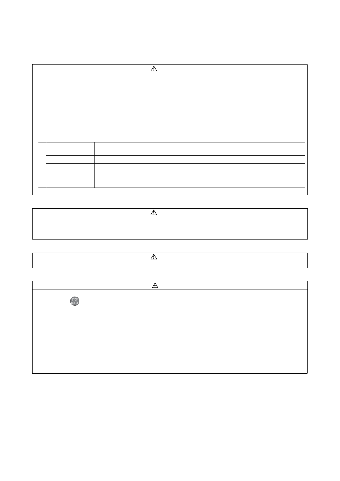
앫 Since pressing key may not stop output depending on the function setting status, provide a circuit and switch separately
to make an emergency stop (power off, mechanical brake operation for emergency stop, etc).
앫 Make sure that the start signal is off before resetting the inverter alarm. A failure to do so may restart the motor suddenly.
앫 The inverter can be started and stopped via the serial port communications link or the field bus. However, please note that
depending on the settings of the communications parameters it may not be possible to stop the system via these connections
if there is an error in the communications system or the data line. In configurations like this it is thus essential to install
additional safety hardware that makes it possible to stop the system in an emergency (e.g. controller inhibit via control signal,
external motor contactor etc). Clear and unambiguous warnings about this must be posted on site for the operating and
service staff.
앫 The load used should be a three-phase induction motor only. Connection of any other electrical equipment to the inverter
output may damage the inverter as well as the equipment.
앫 Do not modify the equipment.
앫 Do not perform parts removal which is not instructed in this manual. Doing so may lead to fault or damage of the inverter.
앫
CAUTION
CAUTION
CAUTION
CAUTION
The electronic thermal relay function does not guarantee protection of the motor from overheating. It is recommended to install
both an external thermal and PTC thermistor for overheat protection.
앫 Do not use a magnetic contactor on the inverter input for frequent starting/stopping of the inverter. Otherwise, the life of the
inverter decreases.
앫 Use a noise filter to reduce the effect of electromagnetic interference and follow the accepted EMC procedures for proper
installation of frequency inverters. Otherwise nearby electronic equipment may be affected.
앫 Take appropriate measures regarding harmonics. Otherwise this can endanger compensation systems or overload generators.
앫 When a 400 V class motor is inverter-driven, please use an insulation-enhanced motor or measures taken to suppress surge
voltages. Surge voltages attributable to the wiring constants may occur at the motor terminals, deteriorating the insulation of
the motor.
앫 When parameter clear or all clear is performed, set again the required parameters before starting operations. Each parameter
returns to the initial value.
앫
The inverter can be easily set for high-speed operation. Before changing its setting, fully examine the performances of the motor
and machine.
앫
The DC braking function of the frequency inverter is not designed to continuously hold a load. Use an electro-mechanical holding
brake on the motor for this purpose.
앫 Before running an inverter which had been stored for a long period, always perform inspection and test operation.
For prevention of damage due to static electricity, touch nearby metal before touching this product to eliminate static electricity
앫
from your body.
앫 If you are installing the inverter to drive a three-phase device while you are contracted for lighting and power service, consult
your electric power supplier.
4.5 Emergency Stop
앫
Provide a safety backup such as an emergency brake which will prevent the machine and equipment from hazardous conditions
if the inverter fails.
앫
When the breaker on the inverter primary side trips, check for the wiring fault (short circuit), damage to internal parts of the inverter,
etc. Identify the cause of the trip, then remove the cause and power on the breaker.
앫
When the protective function is activated (i. e. the frequency inverter switches off with an error message), take the corresponding
corrective action as described in the inverter manual, then reset the inverter, and resume operation.
4.6 Maintenance, Inspection and Parts Replacement
앫 Do not carry out a megger (insulation resistance) test on the control circuit of the inverter. It will cause a failure.
It is recommended to make the following checks periodically:
앫 Check for loose screws in the terminal block. Retighten any loose screws.
앫 Check for dust accumulation on the inverter. Clean the heat sink and the cooling fan of the inverter.
앫 Check for unusual noise generated by the inverter. Retighten installation screw.
앫 Check for the operation condition. Keep the operation condition of inverter as written in the manual.
4.7 Disposal of the Inverter
앫 Disposal of unusable or irreparable devices should always occur in accordance with the applicable country-specific waste-
disposal regulations (e.g. European Waste Code 16 02 14).
5 General Instructions
Many of the diagrams and drawings in instruction manuals show the inverter without a cover, or partially open. Never run the
inverter in this status. Always replace the cover and follow instruction manuals when operating the inverter.
NOTES
앫
The FR-D700 SC complies to the EMC Directive 2004/108/EC and the relevant requirements of EN61800-3:2004 (Second environment/
PDS category "C3").
Therefore the FR-D700 SC is only suitable for use in an industrial environment and not for private use. If you want to use
FR-D700 SC inverter in first environment you will have to add an external RFI filter.
앫 The FR-D700 SC complies to the Low Voltage Directive 2006 and the relevant requirements of EN61800-5-1:2007.
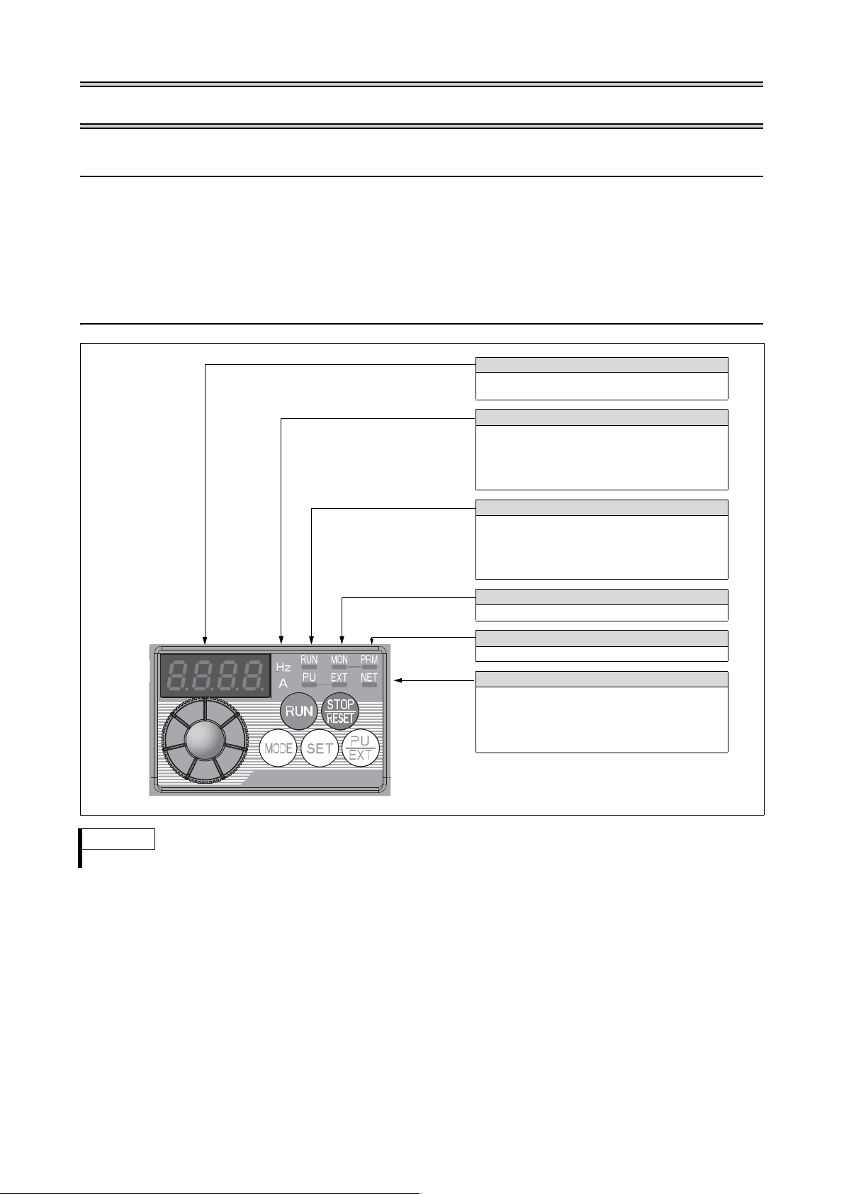
1 PRODUCT DESCRIPTION
LED-Display
4-digit 7-segment display for operational values,
parameter numbers, etc.
Unit Indication
LED to indicate the current unit
앫 Hz: Frequency
앫 A: Current
앫 Off: Voltage
앫 Flicker: Set frequency
Operation Status Display
Lit or flicker during inverter operation
앫 RUN is lit: Forward rotation
앫 RUN flickering slowly: Reverse rotation
앫 RUN flickering fast: Start command is given but the
frequency command is missing
Monitor Indication
Lit to indicate the monitoring mode.
Parameter Setting Mode
Lit to indicate the parameter setting mode.
Operation Mode Indication
LED to indicate the operation mode
앫 PU operation mode (PU)
앫 External operation mode (EXT)
앫 Network operation mode (NET)
앫 Combined operation mode (PU and EXT)
1.1 FR-D700 SC Inverter
An FR-D700 SC frequency inverter is a device that converts the fixed voltage and frequency of the mains power supply into a variable
voltage with a variable frequency. It is installed between the mains supply and the motor and makes continuously-variable speed
adjustment possible.
The adjustable frequency AC drive generates the rotational energy of the motor, which in turn generates the torque of the motor.
It controls induction motors for a variety of automation applications such as air conditioning, conveyor, washing machine, machine
tools, lift machines, etc.
1.2 Operation Panel
NOTE
For detailed description of the operation panel please refer to the "Inverter FR-D700 SC Instruction Manual".
1

2 INSTALLATION OF THE INVERTER AND INSTRUCTIONS
FR - D740 - 036 SC - EC
FR-D740-036SC-EC
FR-D740-036SC-EC
Symbol Voltage Class
D720S Single-phase 200 V class
D740 Three-phase 400 V class
Symbol Type Number
008
to
160
3-digit display
Capacity plate example
Rating plate example
Capacity plate
Rating plate
Serial number
Inverter type
Input rating
Output rating
Serial number
Inverter type
Symbol Control Circuit Terminal Specification
SC Source-logic safety stop function model
Serial number description
A 0 X 123456
Product ID and Lot
Month of construction: 1 to 9 for Jan. to Sep., X to Z for Oct. to Dec.
Last digit of year of construction: 0 for 2010 for example
Alphabetical code of revision
DANGER
Unpack the inverter and check the capacity plate on the front cover and the rating plate on the inverter side face to ensure that
the product agrees with your order and the inverter is intact.
2.2 General Precaution
The bus capacitor discharge time is 10 minutes. Before starting wiring or inspection, switch power off, wait for more than 10 minutes,
and check for residual voltage between terminal P/+ and N/– with a meter etc., to avoid a hazard of electrical shock.
2.3 Environment
Before installation, check that the environment meets following specifications:
Ambient temperature –10 °C to +50 °C (non-freezing)
Ambient humidity
Atmos phere
Altitude
Vibra tion
CAUTION
앫 Install the inverter on a strong surface securely and vertically with bolts.
앫 Leave enough clearances and take cooling measures.
앫 Avoid places where the inverter is subjected to direct sunlight, high temperature and high humidity.
앫 Install the inverter on a non-combustible surface.
90 % RH or less (non-condensing)
Indoors (free from corrosive gas, flammable gas, oil mist, dust and dirt)
Maximum 1000 m above sea level for standard operation. After that derate by 3 % for every extra 500 m up to 2500 m (91 %)
5.9 m/s² or less at 10 to 55 Hz (directions of X, Y, Z axes)
2
INSTALLATION OF THE INVERTER AND INSTRUCTIONS
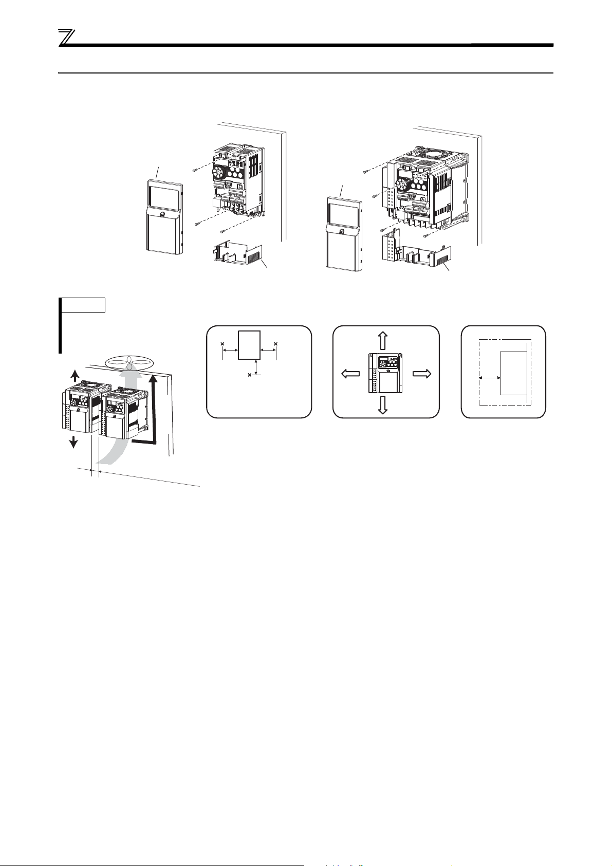
Front cover
Wiring cover
Front cover
FR-D720S-008SC to 042SC FR-D720S-070SC and 100SC, FR-D740-012SC to 160SC
Wiring cover
NOTES
앫
When encasing multiple inverters,
install them in parallel and leave
clearance as a cooling measure
.
앫 Install the inverter vertically.
vertical
R
e
f
e
r
t
o
t
h
e
c
l
e
a
r
a
n
c
e
s
b
e
s
i
d
e
Ambient temperature and humidity Clearances (front)Clearances (side)
5 cm 5 cm
5 cm
Inverter
Measurement
position
Measurement
position
Temperature: –10 °C to +50 °C
Humidity: 90 % RH maximum
10 cm or more
1 cm
or more
*1
10 cm or more
1 cm
or more
*1
1 cm
or
more
*1
Leave enough clearances and
take cooling measures.
*1
When using the inverters at the
ambient temperature of 40 °C or less,
the inverters can be installed
closely attached (0 cm clearance).
When ambient temperature exceeds
40 °C, clearances between the inverter
should be 1 cm or more (5 cm or more
for the FR-D740-120SC or more).
*1
5 cm or more for the
FR-D740-120SC or more
Inverter
2.4 Installation of the Inverter
Enclosure surface mounting
Remove the front cover and wiring cover to fix the inverter to the surface.
3
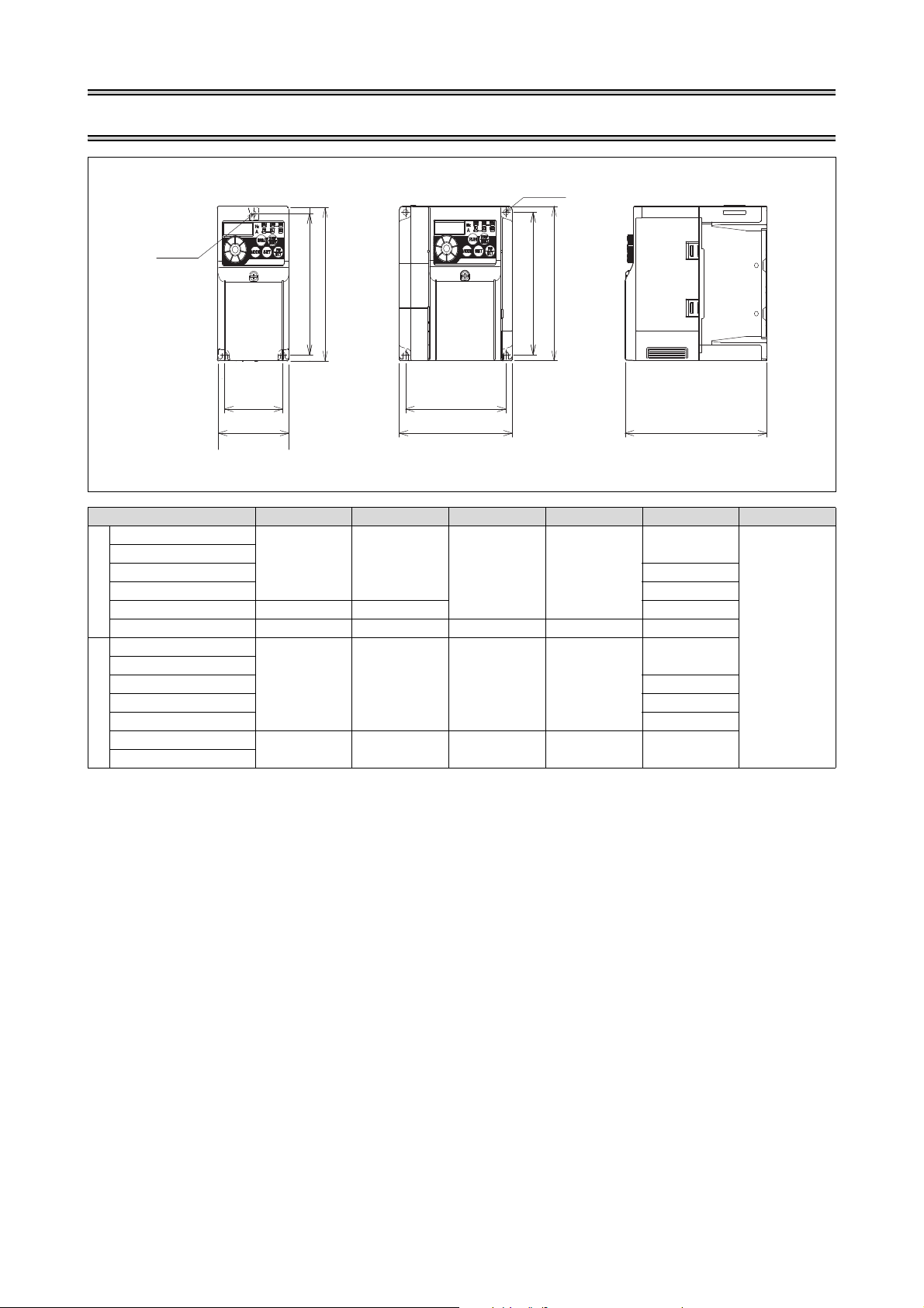
3 OUTLINE DIMENSION DRAWING
W1
W
H1
H
D
W
W1
H1
H
2-ØC hole
1-ØC hole
Inverter Type W W1 H H1 D C
FR-D720S-008SC
FR-D720S-014SC
FR-D720S-025SC 142.5
68 56
128 118
FR-D720S-042SC 162.5
200 V class
FR-D720S-070SC 108 96 155.5
FR-D720S-100SC 140 128 150 138 145
FR-D740-012SC
FR-D740-022SC
FR-D740-036SC 135.5
108 96 128 118
FR-D740-050SC 155.5
FR-D740-080SC 165.5
400 V class
FR-D740-120SC
FR-D740-160SC
220 208 150 138 155
80.5
129.5
(Unit: mm)
5
4
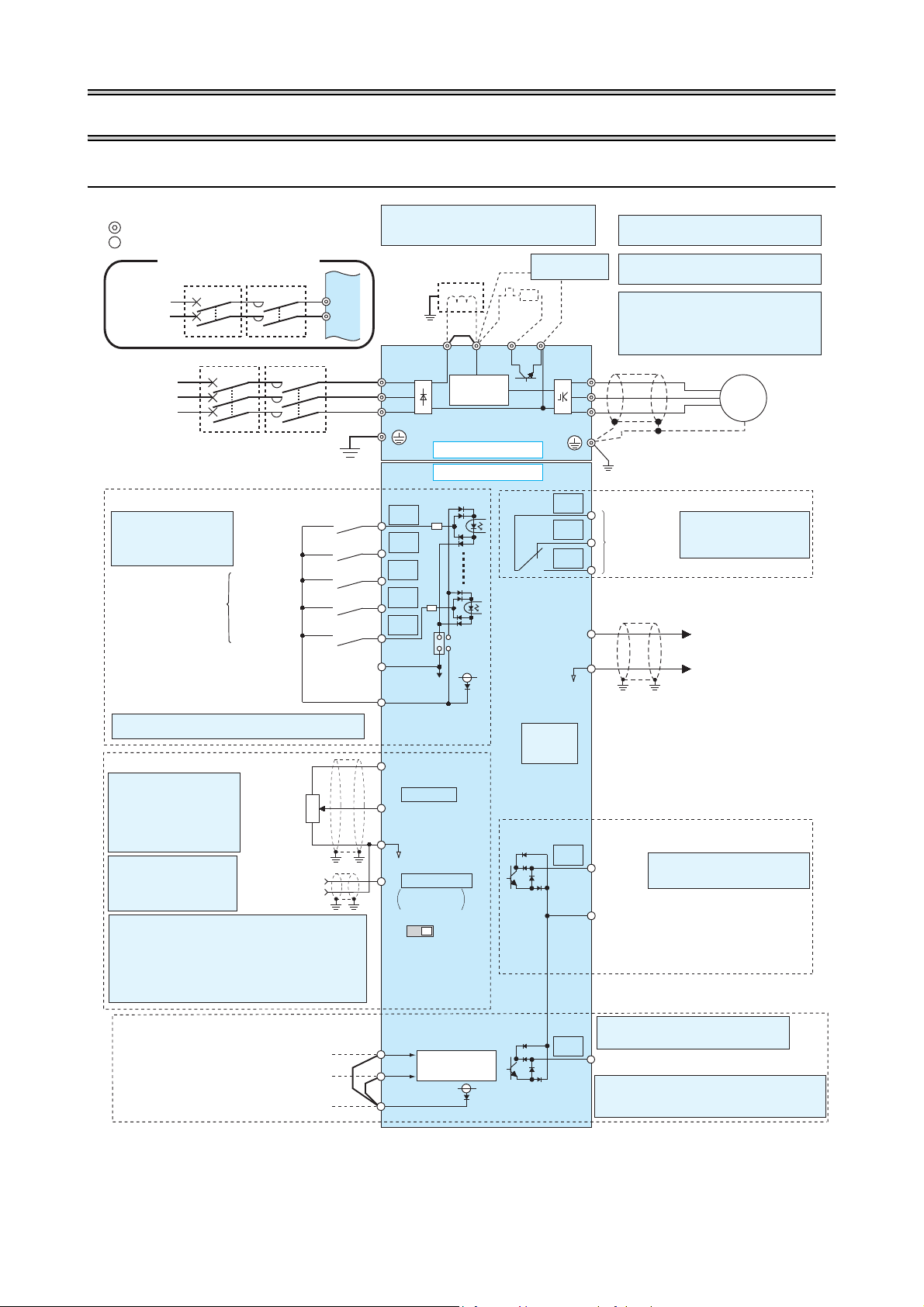
4WIRING
R/L1
P1 P/ +
PR
N/-
S/L2
T/L3
U
V
W
STR
STF
RH
RM
RL
SD
PC
RUN
SE
A
B
C
2
10(+5V)
2
3
1
4
(+)
(-)
5
*4
*1
*8
*2
*3
*5
SINK
SOURCE
VI
*5
AM
5
(+)
(-)
*7
*9
*6
*6
24V
L1
N
S1
S2
SC
SO
24V
Source logic
Main circuit terminal
Control circuit terminal
Jumper
*1 DC reactor
When connecting a DC reactor, remove the
jumper across P1 and P/+.
Earth
Motor
3-phase
AC power
supply
Main circuit
Control circuit
Terminal functions vary with
the input terminal
assignment.
(Pr. 178 to Pr. 182)
Forward
rotation start
Reverse
rotation start
High speed
Medium speed
Low speed
Multi-speed selection
*2 When using terminals PC-SD as a 24 V DC power supply, take
care not to short across terminals PC-SD.
Safety stop input common terminal
Frequency setting signals (analog)
Terminal 4
input
(Current inpu t)
0–5 V DC
0–5 V DC
0–10 V DC
PU
connector
*4 It is recommended to use
a 1 k 2 W potentiometer
when the frequency setting
signal is changed frequently.
Relay output
(Alarm outp ut)
Running
Terminal functions vary by
Pr. 192 "ABC terminal function
selection".
Terminal functions vary with the output
terminal assignment.
(Pr. 190)
Open collector output common
Safety monitor output common
Sink/source common
Frequency
setting
potentiometer
1 k,1/2 W
M
3~
Earth
Brake unit
(Option)
*8 Brake resistor (FR-ABR)
Install a thermal relay to prevent an overheat
and burnout of the brake resistor.
(The brake resistor can not be connected to
the FR-D720S-008SC and 014SC.)
*5 Terminal input specific ations can be changed by analog input
specifications switchover (Pr. 267) (in itial settings in frame).
Set the voltage/current input switch in the "V" position to
select voltage input (0–5 V/0–10 V) and "I" (initial value) to
select current input (0/4–20 mA.)
To use terminal 4 (initial setting is current input), set "4" in any
of Pr.178 to Pr.182 (input terminal function selec tion) to assign
the function, and turn ON AU signal.
Voltage/current
input switch
Relay output
Open collector output
Analog signal output
(0–10 V DC)
0–10 V DC
(Analog common)
4–20 mA DC
*3 Terminal input specifications
can be changed by analog
input specifications switchover (Pr. 73) (initial settings in
frame). Terminal 10 and terminal 2 are used as PTC input
terminal (Pr. 561).
Earth
1-phase
AC power
supply
*7 A brake transistor is not built-in to the
FR-D720S-008SC and 014SC.
Control input signals (no voltage input allowed)
Single-phase power input
Safety stop signal
Safety stop input (Channel 2)
Shorting wire
*6 FR-D720S-008SC to 100SC: +, –
FR-D740-012SC to 160SC: P/+, N/–
MCCB MC
MCCB MC
Inrush
current limit
circuit
Terminal functions vary with the output
terminal assignment. (Pr. 197)
Safety monitor output
*9 Common terminal of terminal SO is terminal SE.
Output shutoff
circuit
Safety stop input (Channel 1)
24 V DC power supply/max. 100 mA load current
Contact input common (Source*)
Contact input common (Sink*),
24 V DC power supply common
*(Common for external power supply transistor)
4.1 Terminal Connection Diagram
5
WIRING
Screw size (M3,5)
Jumper
Screw size
(M3,5)
Motor
Power supply
M
3 ~
L1 N
Jumper
Power supply
Screw size
(M4)
Motor
M
3 ~
L1 N
Screw size (M4)
N/-
P/+
Screw size (M4)
Jumper
Screw size
(M4)
Motor
Power supply
M
3 ~
L1L2 L3
N/-
P/+
Jumper
Power supply
Screw size
(M4)
Motor
M
3 ~
L1 L2 L3
Screw size (M4)
CAUTION
앫 To prevent a malfunction due to noise, keep the signal cables more than 10 cm away from the power cables. Also separate the main circuit wire
of the input side and the output side.
앫 After wiring, wire offcuts must not be left in the inverter.
Wire offcuts can cause an alarm, failure or malfunction. Always keep the inverter clean. When drilling mounting holes in a control box etc., take
care not to allow chips and other foreign matter to enter the inverter.
앫 Set the voltage/current input switch in the correct position. An incorrect setting may cause a fault, failure or malfunction.
앫 The output of the single-phase power input specification is three-phase 230 V.
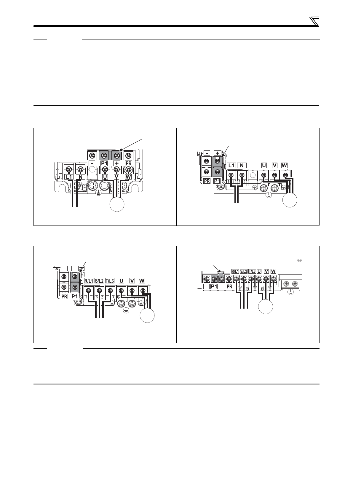
4.2 Main Circuit Terminal Specifications
4.2.1 Terminal Arrangement of the Main Circuit Terminal, Power Supply and the Motor Wiring
Single-Phase 200 V Class
FR-D720S-008SC to 042SC FR-D720S-070SC and 100SC
Three-Phase 400 V Class
FR-D740-012SC to 080SC FR-D740-120SC, 160SC
CAUTION
앫 Make sure the power cables are connected to the R/L1, S/L2, T/L3 (three-phase 400 V class) resp. to the L1, N (for single-phase
200 V class). Never connect the power cable to the U, V, W of the inverter. Doing so will damaged the inverter. (Phase sequence
needs not to be matched.)
앫 Connect the motor to U, V, W. At this time turning on the forward rotation switch (signal) rotates the motor in the clockwise
direction when viewed on the motor shaft.
6
 Loading...