

Page 1
INVERTER
FR-D700
INSTRUCTION MANUAL
FR-D720-008 to 318 - NA
FR-D740-012 to 160 - NA
FR-D720S-008 to 100 - NA
OUTLINE
1
WIRING
PRECAUTIONS FOR USE
OF THE INVERTER
PARAMETERS
TROUBLESHOOTING
PRECAUTIONS FOR
MAINTENANCE AND INSPECTION
2
3
4
5
6
SPECIFICATIONS
7
Page 2
Thank you for choosing this Mitsubishi Inverter.
WARNING
This Instruction Manual provides instructions for advanced use of the FR-D700 series inverters.
Incorrect handling might cause an unexpected fault. Before using the inverter, always read this instruction manual
and the Installation Guideline [IB-0600367ENG] packed with the product carefully to use the equipment to its
optimum performance.
1. Electric Shock Prevention
This section is specifically about safety matters
Do not attempt to install, operate, maintain or inspect the
inverter until you have read through the Instruction Manual
and appended documents carefully and can use the
equipment correctly. Do not use this product until you have
a full knowledge of the equipment, safety information and
instructions.
In this Instruction Manual, the safety instruction levels are
classified into "WARNING" and "CAUTION".
WARNING
CAUTION
Note that even the level may lead to a serious
consequence according to conditions. Please follow the
instructions of both levels because they are important to
personnel safety.
Assumes that incorrect handling may
cause hazardous conditions, resulting
in death or severe injury.
Assumes that incorrect handling may
cause hazardous conditions, resulting
in medium or slight injury, or may
cause physical damage only.
CAUTION
While power is on or
open the front cover. Otherwise you may get an electric
shock.
Do not run the inverter with the front cover or wiring cover
removed. Otherwise, you may access the exposed highvoltage terminals or the charging part of the circuitry and
get an electric shock.
Even if power is off, do not remove the front cover except
for wiring or periodic inspection. You may access the
charged inverter circuits and get an electric shock.
Before starting wiring or inspection, switch off power,
check to make sure that the operation panel indicator is
off, wait for at least 10 minutes after the power supply has
been switched off, and check that there are no residual
voltage using a tester or the like. The capacitor is charged
with high voltage for some time after power off and it is
dangerous.
This inverter must be earthed (grounded). Earthing
(grounding) must conform to the requirements of national
and local safety regulations and electrical code. (NEC
section 250, IEC 536 class 1 and other applicable
standards)
Use an neutral-point earthed (grounded) power supply for
400V class inverter in compliance with EN standard.
Any person who is involved in the wiring or inspection of
this equipment should be fully competent to do the work.
Always install the inverter before wiring. Otherwise, you
may get an electric shock or be injured.
Perform setting dial and key operations with dry hands to
prevent an electric shock. Otherwise you may get an
electric shock.
Do not subject the cables to scratches, excessive stress,
heavy loads or pinching. Otherwise, you may get an
electric shock.
Do not change the cooling fan while power is on. It is
dangerous to change the cooling fan while power is on.
Do not touch the printed circuit board with wet hands.
Otherwise, you may get an electric shock.
When measuring the main circuit capacitor capacity, the
DC voltage is applied to the motor for 1s at powering off.
Never touch the motor terminal, etc. right after powering
off to prevent an electric shock.
when the inverter is running, do not
2. Fire Prevention
CAUTION
Install the inverter on a nonflammable wall without holes
(so that nobody can touch the inverter heatsink on the rear
side, etc.). Mounting it to or near flammable material can
cause a fire.
If the inverter has become faulty, switch off the inverter
power. A continuous flow of large current could cause a
fire.
When using a brake resistor, make up a sequence that will
turn off power when an alarm signal is output. Otherwise,
the brake resistor may excessively overheat due to
damage of the brake transistor and such, causing a fire.
Do not connect a resistor directly to the DC terminals P/+
and N/-. This could cause a fire.
A-1
Page 3
3.Injury Prevention
WARNING
CAUTION
Apply only the voltage specified in the instruction manual
to each terminal. Otherwise, burst, damage, etc. may
occur.
Ensure that the cables are connected to the correct
terminals. Otherwise, burst, damage, etc. may occur.
Always make sure that polarity is correct to prevent
damage, etc. Otherwise, burst, damage, etc. may occur.
While power is on or for some time after power-off, do not
touch the inverter as they will be extremely hot. Doing so
can cause burns.
4. Additional Instructions
Also note the following points to prevent an accidental failure,
injury, electric shock, etc.
(1) Transportation and mounting
CAUTION
Transport the product using the correct method that
corresponds to the weight. Failure to observe this could
lead to injuries.
Do not stack the inverter boxes higher than the number
recommended.
Ensure that installation position and material can
withstand the weight of the inverter. Install according to
the information in the instruction manual.
Do not install or operate the inverter if it is damaged or
has parts missing.
When carrying the inverter, do not hold it by the front
cover or setting dial; it may fall off or fail.
Do not stand or rest heavy objects on the product.
Check the inverter mounting orientation is correct.
Prevent other conductive bodies such as screws and
metal fragments or other flammable substance such as oil
from entering the inverter.
As the inverter is a precision instrument, do not drop or
subject it to impact.
Use the inverter under the following environmental
conditions: Otherwise, the inverter may be damaged.
Surrounding
air
temperature
Ambient
humidity
Storage
temperature
Atmosphere
Environment
Altitude/
vibration
∗1 Temperature applicable for a short time, e.g. in transit.
-10°C to +50°C (14°F to 122°F) (non-freezing)
90%RH maximum (non-condensing)
2
or less
(-4°F to 149°F)
-20°C to +65°C
Indoors (free from corrosive gas, flammable gas,
oil mist, dust and dirt)
Maximum 1000m (3280.80feet) above sea level for
standard operation. After that derate by 3% for
every extra 500m (1640.40feet) up to 2500m
(8202feet) (91%).
5.9m/s
*1
(2) Wiring
CAUTION
Do not install a power factor correction capacitor or surge
suppressor/capacitor type filter on the inverter output
side. These devices on the inverter output side may be
overheated or burn out.
The connection orientation of the output cables U, V, W to
the motor will affect the direction of rotation of the motor.
(3) Trial run
CAUTION
Before starting operation, confirm and adjust the
parameters. A failure to do so may cause some machines
to make unexpected motions.
(4) Usage
When you have chosen the retry function, stay away from
the equipment as it will restart suddenly after trip.
Since pressing key may not stop output depending
on the function setting status, provide a circuit and switch
separately to make an emergency stop (power off,
mechanical brake operation for emergency stop, etc).
Make sure that the start signal is off before resetting the
inverter alarm. A failure to do so may restart the motor
suddenly.
The load used should be a three-phase induction motor only.
Connection of any other electrical equipment to the
inverter output may damage the equipment.
Do not modify the equipment.
Do not perform parts removal which is not instructed in this
manual. Doing so may lead to fault or damage of the product.
CAUTION
The electronic thermal relay function does not guarantee
protection of the motor from overheating. It is recommended
to install both an external thermal and PTC thermistor for
overheat protection.
Do not use a magnetic contactor on the inverter input for
frequent starting/stopping of the inverter. Otherwise, the
life of the inverter decreases.
Use a noise filter to reduce the effect of electromagnetic
interference. Otherwise nearby electronic equipment may
be affected.
Take measures to suppress harmonics. Otherwise power
supply harmonics from the inverter may heat/damage the
power factor correction capacitor and generator.
When a 400V class motor is inverter-driven, please use an
insulation-enhanced motor or measures taken to
suppress surge voltages. Surge voltages attributable to
the wiring constants may occur at the motor terminals,
deteriorating the insulation of the motor.
When parameter clear or all parameter clear is performed,
reset the required parameters before starting operations.
Each parameter returns to the initial value.
The inverter can be easily set for high-speed operation.
Before changing its setting, fully examine the
performances of the motor and machine.
In addition to the inverter’s holding function, install a
holding device to ensure safety.
Before running an inverter which had been stored for a
long period, always perform inspection and test
operation.
For prevention of damage due to static electricity, touch
nearby metal before touching this product to eliminate
static electricity from your body.
A-2
Page 4

(5) Emergency stop
CAUTION
Provide a safety backup such as an emergency brake
which will prevent the machine and equipment from
hazardous conditions if the inverter fails.
When the breaker on the inverter input side trips, check
for the wiring fault (short circuit), damage to internal parts
of the inverter, etc. Identify the cause of the trip, then
remove the cause and power on the breaker.
When any protective function is activated, take the
appropriate corrective action, then reset the inverter, and
resume operation.
(6) Maintenance, inspection and parts replacement
CAUTION
Do not carry out a megger (insulation resistance) test on
the control circuit of the inverter. It will cause a failure.
(7) Disposal
CAUTION
Treat as industrial waste.
General instruction
Many of the diagrams and drawings in this Instruction
Manual show the inverter without a cover, or partially open.
Never operate the inverter in this manner. Always replace
the cover and follow this Instruction Manual when operating
the inverter.
A-3
Page 5

CONTENTS
1 OUTLINE 1
1.1 Product checking and parts identification......................................... 2
1.2 Inverter and peripheral devices.......................................................... 3
1.2.1 Peripheral devices .......................................................................................................................... 4
1.3 Removal and reinstallation of the cover ............................................ 5
1.3.1 Front cover...................................................................................................................................... 5
1.3.2 Wiring cover.................................................................................................................................... 7
1.4 Installation of the inverter and enclosure design.............................. 8
1.4.1 Inverter installation environment..................................................................................................... 8
1.4.2 Cooling system types for inverter enclosure................................................................................. 10
1.4.3 Inverter placement ........................................................................................................................ 11
2 WIRING 13
2.1 Wiring................................................................................................. 14
2.1.1 Terminal connection diagram ....................................................................................................... 14
2.2 Main circuit terminal specifications................................................. 15
2.2.1 Specification of main circuit terminal ............................................................................................ 15
2.2.2 Terminal arrangement of the main circuit terminal, power supply and the motor wiring............... 15
2.2.3 Cables and wiring length .............................................................................................................. 17
2.3 Control circuit specifications ........................................................... 20
2.3.1 Control circuit terminal .................................................................................................................. 20
2.3.2 Changing the control logic ............................................................................................................ 22
2.3.3 Wiring of control circuit ................................................................................................................. 24
2.3.4 Wiring instructions ........................................................................................................................ 28
2.3.5 Connection to the PU connector................................................................................................... 29
2.4 Connection of stand-alone option unit ............................................. 31
2.4.1 Connection of a dedicated external brake resistor (MRS type, MYS type, FR-ABR)
(FR-D720-025 or more, FR-D740-012 or more, FR-D720S-025 or more) ................................... 31
2.4.2 Connection of the brake unit (FR-BU2) ........................................................................................ 33
2.4.3 Connection of the high power factor converter (FR-HC) .............................................................. 34
2.4.4 Connection of the power regeneration common converter (FR-CV) ............................................ 35
2.4.5 Connection of a DC reactor (FR-HEL).......................................................................................... 35
3 PRECAUTIONS FOR USE OF THE INVERTER 37
3.1 EMC and leakage currents................................................................ 38
I
Page 6

3.1.1 Leakage currents and countermeasures ...................................................................................... 38
3.1.2 EMC measures ............................................................................................................................. 40
3.1.3 Power supply harmonics .............................................................................................................. 42
3.2 Installation of power factor improving reactor ............................... 43
3.3 Power-off and magnetic contactor (MC).......................................... 44
3.4 Inverter-driven 400V class motor .................................................... 45
3.5 Precautions for use of the inverter .................................................. 46
3.6 Failsafe of the system which uses the inverter .............................. 48
4 PARAMETERS 51
4.1 Operation panel ................................................................................ 52
4.1.1 Names and functions of the operation panel ................................................................................ 52
4.1.2 Basic operation (factory setting) ................................................................................................... 53
4.1.3 Easy operation mode setting (easy setting mode) ....................................................................... 54
4.1.4 Change the parameter setting value ............................................................................................ 55
4.1.5 Setting dial push ........................................................................................................................... 55
4.2 Parameter list ................................................................................... 56
4.2.1 Parameter list ............................................................................................................................... 56
4.3 Adjust the output torque (current) of the motor............................. 73
CONTENTS
4.3.1 Manual torque boost (Pr. 0, Pr. 46) ............................................................................................. 73
4.3.2 Large starting torque and low speed torque are necessary (General-purpose magnetic flux vector
control (Pr. 71, Pr. 80)) ................................................................................................................ 75
4.3.3 Slip compensation (Pr. 245 to Pr. 247)........................................................................................ 78
4.3.4 Stall prevention operation (Pr. 22, Pr. 23, Pr. 48, Pr. 66, Pr. 156, Pr. 157)................................. 79
4.4 Limit the output frequency.............................................................. 83
4.4.1 Maximum/minimum frequency (Pr. 1, Pr. 2, Pr. 18) .................................................................... 83
4.4.2 Avoid mechanical resonance points (frequency jumps) (Pr. 31 to Pr. 36)................................... 84
4.5 Set V/F pattern................................................................................. 85
4.5.1 Base frequency, voltage (Pr. 3, Pr. 19, Pr. 47) ............................................................................ 85
4.5.2 Load pattern selection (Pr. 14) .................................................................................................... 87
4.6 Frequency setting by external terminals........................................ 89
4.6.1 Operation by multi-speed operation (Pr. 4 to Pr. 6, Pr. 24 to Pr. 27, Pr. 232 to Pr. 239) ............ 89
4.6.2 Jog operation (Pr. 15, Pr. 16) ...................................................................................................... 91
4.6.3 Remote setting function (Pr. 59).................................................................................................. 93
4.7 Setting of acceleration/deceleration time and acceleration/
deceleration pattern........................................................................ 96
II
Page 7

4.7.1 Setting of the acceleration and deceleration time
(Pr. 7, Pr. 8, Pr. 20, Pr. 44, Pr. 45) ............................................................................................. 96
4.7.2 Starting frequency and start-time hold function (Pr. 13, Pr. 571)................................................. 98
4.7.3 Acceleration/deceleration pattern (Pr. 29) ................................................................................... 99
4.8 Selection and protection of a motor.............................................. 100
4.8.1 Motor overheat protection (Electronic thermal O/L relay, PTC thermistor protection) (Pr. 9, Pr. 51,
Pr. 561) ...................................................................................................................................... 100
4.8.2 Applied motor (Pr. 71, Pr. 450) .................................................................................................. 103
4.8.3 To exhibit the best performance of the motor (offline auto tuning)
(Pr. 71, Pr. 80, Pr. 82 to Pr. 84, Pr. 90, Pr. 96).......................................................................... 105
4.9 Motor brake and stop operation .................................................... 109
4.9.1 DC injection brake (Pr. 10 to Pr. 12).......................................................................................... 109
4.9.2 Selection of a regenerative brake (Pr. 30, Pr. 70) ..................................................................... 110
4.9.3 Stop selection (Pr. 250) ............................................................................................................. 112
4.10 Function assignment of external terminal and control ................ 113
4.10.1 Input terminal function selection (Pr. 178 to Pr. 182)................................................................. 113
4.10.2 Inverter output shutoff signal (MRS signal, Pr. 17) .................................................................... 115
4.10.3 Condition selection of function validity by second function selection signal (RT) ...................... 116
4.10.4 Start signal operation selection (STF, STR, STOP signal, Pr. 250) .......................................... 117
4.10.5 Output terminal function selection (Pr. 190, Pr. 192)................................................................. 119
4.10.6 Detection of output frequency (SU, FU signal, Pr. 41 to Pr. 43) ................................................ 123
4.10.7 Output current detection function
(Y12 signal, Y13 signal, Pr. 150 to Pr. 153, Pr. 166, Pr. 167) ................................................... 124
4.10.8 Remote output selection (REM signal, Pr. 495, Pr. 496) ........................................................... 126
4.11 Monitor display and monitor output signal.................................... 127
4.11.1 Speed display and speed setting (Pr. 37).................................................................................. 127
4.11.2 Monitor display selection of operation panel/PU and terminal AM
(Pr. 52, Pr.158, Pr. 170, Pr. 171, Pr. 268, Pr. 563, Pr. 564, Pr. 891)......................................... 128
4.11.3 Reference of the terminal AM (analog voltage output) (Pr. 55, Pr. 56)...................................... 133
4.11.4 Terminal AM calibration (calibration parameter C1 (Pr.901)) .................................................... 134
4.12 Operation selection at power failure and instantaneous power
failure ............................................................................................. 136
4.12.1 Automatic restart after instantaneous power failure/flying start
(Pr. 30, Pr. 57, Pr. 58, Pr. 96, Pr. 162, Pr. 165, Pr. 298, Pr. 299, Pr. 611) ................................ 136
4.12.2 Power-failure deceleration stop function (Pr. 261)..................................................................... 142
4.13 Operation setting at fault occurrence........................................... 144
4.13.1 Retry function (Pr. 65, Pr. 67 to Pr. 69) ..................................................................................... 144
4.13.2 Input/output phase loss protection selection (Pr. 251, Pr. 872) ................................................. 146
4.13.3 Earth (ground) fault detection at start (Pr. 249) ......................................................................... 146
4.14 Energy saving operation ................................................................ 147
III
Page 8

4.14.1 Optimum excitation control (Pr. 60) ........................................................................................... 147
4.15 Motor noise, EMI measures, mechanical resonance.................... 148
4.15.1 PWM carrier frequency and Soft-PWM control (Pr. 72, Pr. 240, Pr. 260) ................................. 148
4.15.2 Speed smoothing control (Pr. 653)............................................................................................ 149
4.16 Frequency setting by analog input (terminal 2, 4) ....................... 150
4.16.1 Analog input selection (Pr. 73, Pr. 267) ..................................................................................... 150
4.16.2 Response level of analog input and noise elimination (Pr. 74).................................................. 152
4.16.3 Bias and gain of frequency setting voltage (current)
(Pr. 125, Pr. 126, Pr. 241, C2 (Pr. 902) to C7 (Pr. 905)) ........................................................... 153
4.17 Misoperation prevention and parameter setting restriction........ 158
4.17.1 Reset selection/disconnected PU detection/PU stop selection (Pr. 75) .................................... 158
4.17.2 Parameter write disable selection (Pr. 77)................................................................................. 161
4.17.3 Reverse rotation prevention selection (Pr. 78) .......................................................................... 162
4.17.4 Extended parameter display (Pr. 160) ....................................................................................... 162
4.17.5 Password function (Pr. 296, Pr. 297)......................................................................................... 163
4.18 Selection of operation mode and operation location ................... 165
4.18.1 Operation mode selection (Pr. 79)............................................................................................. 165
4.18.2 Operation mode at power-on (Pr. 79, Pr. 340) .......................................................................... 175
4.18.3 Start command source and frequency command source during communication
operation (Pr. 338, Pr. 339, Pr. 551) ......................................................................................... 176
4.19 Communication operation and setting ......................................... 180
CONTENTS
4.19.1 Wiring and configuration of PU connector ................................................................................. 180
4.19.2 Initial settings and specifications of RS-485 communication
(Pr. 117 to Pr. 120, Pr. 123, Pr. 124, Pr. 549) ........................................................................... 183
4.19.3 Operation selection at communication error occurrence (Pr. 121, Pr. 122, Pr. 502) ................. 184
4.19.4 Communication EEPROM write selection (Pr. 342) .................................................................. 187
4.19.5 Mitsubishi inverter protocol (computer link communication) ...................................................... 188
4.19.6 Modbus RTU communication specifications
(Pr. 117, Pr. 118, Pr. 120, Pr. 122, Pr. 343, Pr. 502, Pr. 549) ................................................... 200
4.20 Special operation and frequency control ..................................... 212
4.20.1 PID control (Pr. 127 to Pr. 134, Pr. 575 to Pr. 577) ................................................................... 212
4.20.2 Dancer control (Pr. 44, Pr. 45, Pr. 128 to Pr. 134) .................................................................... 220
4.20.3 Regeneration avoidance function (Pr. 665, Pr. 882, Pr. 883, Pr. 885, Pr. 886)......................... 226
4.21 Useful functions ............................................................................ 228
4.21.1 Cooling fan operation selection (Pr. 244) .................................................................................. 228
4.21.2 Display of the life of the inverter parts (Pr. 255 to Pr. 259)........................................................ 229
4.21.3 Maintenance timer alarm (Pr. 503, Pr. 504) .............................................................................. 233
4.21.4 Current average value monitor signal (Pr. 555 to Pr. 557) ........................................................ 234
4.21.5 Free parameter (Pr. 888, Pr. 889) ............................................................................................. 236
IV
Page 9

4.22 Setting the parameter unit and operation panel........................... 237
4.22.1 RUN key rotation direction selection (Pr. 40)............................................................................. 237
4.22.2 PU display language selection(Pr.145)...................................................................................... 237
4.22.3 Operation panel frequency setting/key lock operation selection (Pr. 161)................................. 238
4.22.4 Magnitude of frequency change setting (Pr. 295)...................................................................... 240
4.22.5 Buzzer control (Pr. 990)............................................................................................................. 241
4.22.6 PU contrast adjustment (Pr. 991) .............................................................................................. 241
4.23 Parameter clear/ All parameter clear............................................ 242
4.24 Initial value change list ................................................................. 243
4.25 Check and clear of the faults history ............................................ 244
5 TROUBLESHOOTING 247
5.1 Reset method of protective function.............................................. 248
5.2 List of fault or alarm indications .................................................... 249
5.3 Causes and corrective actions ....................................................... 250
5.4 Correspondences between digital and actual characters............. 259
5.5 Check first when you have some troubles ..................................... 260
5.5.1 Motor will not start....................................................................................................................... 260
5.5.2 Motor generates abnormal noise ................................................................................................ 260
5.5.3 Motor generates heat abnormally ............................................................................................... 261
5.5.4 Motor rotates in opposite direction.............................................................................................. 261
5.5.5 Speed greatly differs from the setting ......................................................................................... 261
5.5.6 Acceleration/deceleration is not smooth ..................................................................................... 261
5.5.7 Motor current is large.................................................................................................................. 261
5.5.8 Speed does not increase ............................................................................................................ 261
5.5.9 Speed varies during operation.................................................................................................... 262
5.5.10 Operation mode is not changed properly....................................................................................262
5.5.11 Operation panel display is not operating .................................................................................... 262
5.5.12 Parameter write cannot be performed ........................................................................................ 262
6 PRECAUTIONS FOR MAINTENANCE AND INSPECTION 263
6.1 Inspection items .............................................................................264
6.1.1 Daily inspection........................................................................................................................... 264
6.1.2 Periodic inspection...................................................................................................................... 264
6.1.3 Daily and periodic inspection ...................................................................................................... 265
6.1.4 Display of the life of the inverter parts ........................................................................................ 266
6.1.5 Checking the inverter and converter modules ............................................................................ 266
V
Page 10

6.1.6 Cleaning ..................................................................................................................................... 266
6.1.7 Replacement of parts ................................................................................................................. 267
6.2 Measurement of main circuit voltages, currents and powers ...... 271
6.2.1 Measurement of powers ............................................................................................................. 273
6.2.2 Measurement of voltages and use of PT.................................................................................... 273
6.2.3 Measurement of currents............................................................................................................ 274
6.2.4 Use of CT and transducer .......................................................................................................... 274
6.2.5 Measurement of inverter input power factor ............................................................................... 274
6.2.6 Measurement of converter output voltage (across terminals P and N) ...................................... 274
6.2.7 Insulation resistance test using megger ..................................................................................... 275
6.2.8 Pressure test .............................................................................................................................. 275
7 SPECIFICATIONS 277
7.1 Rating.............................................................................................. 278
7.2 Common specifications.................................................................. 280
CONTENTS
7.3 Outline dimension drawings........................................................... 281
APPENDIX 285
Appendix1 Index........................................................................................................... 286
VI
Page 11

MEMO
VII
Page 12

1 OUTLINE
This chapter explains the "OUTLINE" for use of this product.
Always read the instructions before using the equipment
1.1 Product checking and parts identification ................................. 2
1.2 Inverter and peripheral devices................................................... 3
1.3 Removal and reinstallation of the cover..................................... 5
1.4 Installation of the inverter and enclosure design ...................... 8
<Abbreviations>
PU .................................................. Operation panel and parameter unit (FR-PU04
Inverter ........................................... Mitsubishi inverter FR-D700 series
D700 ........................................ Mitsubishi inverter FR-D700 series
FR-
Pr.................................................... Parameter number
PU operation .................................. Operation using the PU (operation panel/FR-PU04/FR-PU07)
External operation .......................... Operation using the control circuit signals
Combined operation ....................... Operation using both the PU (operation panel/FR-PU04/FR-
PU07) and external operation
Operation panel for E500, PA02..... FR-E500 series operation panel (FR-PA02-02)
Mitsubishi standard motor .............. SF-JR
Mitsubishi constant-torque motor ... SF-HRCA
<Trademarks>
Microsoft and Visual C++ are registered trademarks of Microsoft Corporation in the United States
and/or other countries.
Company and product names herein are the trademarks and registered trademarks of their
respective owners.
<Mark>
/FR-PU07)
1
2
3
4
5
REMARKS :Additional helpful contents and relations with other functions are stated
NOTE :Contents requiring caution or cases when set functions are not
activated are stated.
POINT :Useful contents and points are stated.
Parameters referred to : related parameters are stated.
6
7
1
Page 13
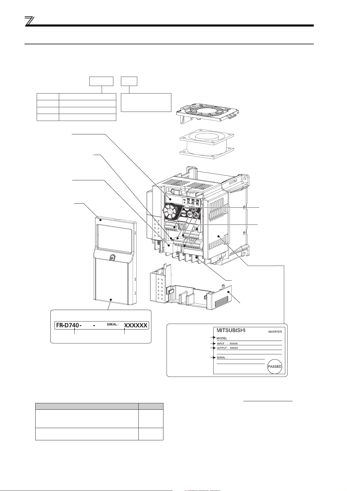
Product checking and parts identification
1.1 Product checking and parts identification
Unpack the inverter and check the capacity plate on the front cover and the rating plate on the inverter side face to ensure that
the product agrees with your order and the inverter is intact.
Inverter type
--
FR
D740 036
- NA
Symbol Voltage class
D720
D740
D720S
Operation panel
(Refer to page 52)
Voltage/current input switch
(Refer to page 20)
PU connector
(Refer to page 21)
Front cover
(Refer to page 5)
Three-phase 200V class
Three-phase 400V class
Single-phase 200V class
Displays the rated
current
Cooling fan
(Refer to page 267)
Control circuit terminal
block
(Refer to page 20)
Control logic switchover
jumper connector
(Refer to page 22)
Capacity plate
036 NA
Inverter type
Serial number
• Accessory
· Fan cover fixing screws (M3 × 35mm)
These screws are necessary for compliance with the European Directive
Type Number
FR-D720-070 to 165
FR-D740-036 to 080
FR-D720S-070, 100
FR-D720-120, 160
FR-D740-120, 160
1
2
Rating plate
Inverter type
Input rating
Output rating
Serial number
Main circuit
terminal block
(Refer to page 15)
Combed shaped
wiring cover
(Refer to page 7)
FR-D740-036-NA
(
Refer to Installation Guideline
)
2
Page 14
1.2 Inverter and peripheral devices
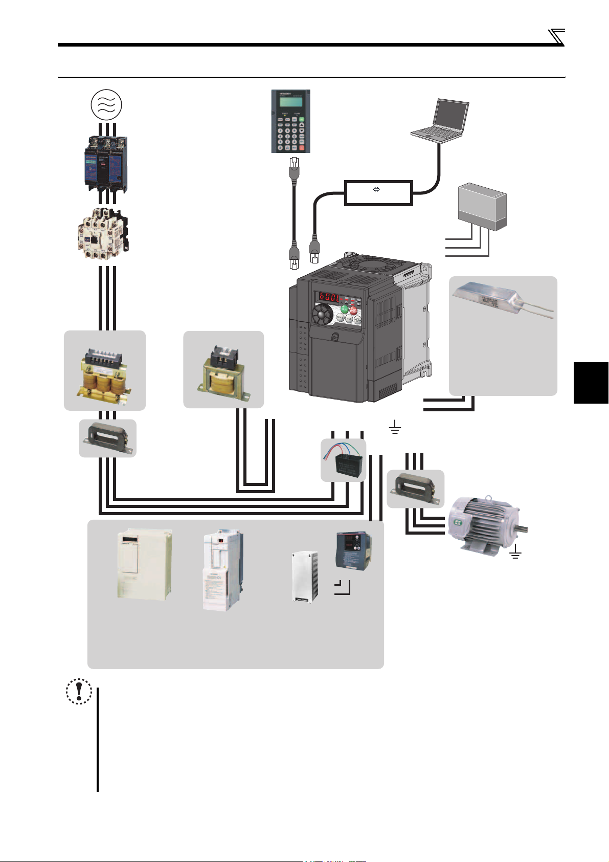
Inverter and peripheral devices
AC reactor (FR-HAL)
Three-phase AC power supply
Use within the permissible power supply
specifications of the inverter. To ensure
safety, use a moulded case circuit breaker,
earth leakage circuit breaker or magnetic
contactor to switch power ON/OFF.
(Refer to page 281)
Moulded case circuit breaker
(MCCB) or earth leakage circuit
breaker (ELB), fuse
The breaker must be selected carefully
since an in-rush current flows in the
inverter at power on.
(Refer to page 4)
Magnetic contactor (MC)
Install the magnetic contactor to ensure
safety. Do not use this magnetic contactor
to start and stop the inverter. Doing so will
cause the inverter life to be shorten.
(Refer to page 44)
Reactor (FR-HAL, FR-HEL option)
Reactors (option) must be used when
power harmonics measures are taken,
the power factor is to be improved or the
inverter is installed near a large power
supply system (500kVA or more). The
inverter may be damaged if you do not
use reactors. Select the reactor according
to the model. Remove the jumpers across
terminals P/+ and P1 to connect the DC reactor.
DC reactor (FR-HEL)
Noise filter
(FR-BSF01, FR-BLF)
Install a noise filter to reduce
the electromagnetic noise
generated from the inverter.
Effective in the range from
about 1MHz to 10MHz. When
more wires are passed
through, a more effective result
can be obtained. A wire should
be wound four turns or more.
P/+
P1
Parameter unit (FR-PU07)
By connecting the connection cable
(FR-CB2) to the PU connector,
operation can be performed from
FR-PU07.
(Refer to page 29)
Inverter (FR-D700)
Capacitor type
filter
(FR-BIF)
Reduces the
radio noise.
RS-485 RS-232C
R/L1 S/L2T/L3
Converter
Earth (Ground)
N/-
P/+
P/+
PR
UW
V
RS-232C - RS-485 converter is
required when connecting to PC
with RS-232C interface.
(Refer to page 180)
S1
S2
SC
Brake resistor (FR-ABR,
MRS type, MYS type)
Braking capability can be
improved.
(FR-D720-025 or more,
FR-D740-012 or more,
FR-D720S-025 or more)
(Refer to page 31)
Noise filter
(FR-BSF01, FR-BLF)
Install a noise filter to reduce the
electromagnetic noise generated
from the inverter.
Effective in the range from about
1MHz to 10MHz. A wire should be
wound four turns at a maximum.
Safety relay module
Required for
compliance with
safety standard.
Motor
1
OUTLINE
Brake unit
(FR-BU2)
Earth (Ground)
High power factor
converter (FR-HC)
Power supply harmonics
can be greatly suppressed.
Install this as required.
Power regeneration
common converter
(FR-CV)
Great braking capability
is obtained.
Install this as required.
PR
P/+
P/+
PR
Resistor unit (FR-BR)
Discharging resistor (GZG, GRZG)
The regenerative braking capability
of the inverter can be exhibited fully.
Install this as required.
Devices connected to the output
Do not install a power factor correction capacitor,
surge suppressor or capacitor type filter on the output
side of the inverter. When installing a moulded case
circuit breaker on the output side of the inverter,
contact each manufacturer for selection of the
moulded case circuit breaker.
Earth (Ground)
To prevent an electric shock, always earth (ground)
the motor and inverter. For reduction of induction noise
from the power line of the inverter, it is recommended
to wire the earth (ground) cable by returning it to the
earth (ground) terminal of the inverter.
NOTE
The life of the inverter is influenced by surrounding air temperature. The surrounding air temperature should be as low as
possible within the permissible range. This must be noted especially when the inverter is installed in an enclosure.
Wrong wiring might lead to damage of the inverter. The control signal lines must be kept fully away from the main
circuit to protect them from noise. (Refer to page 14)
Do not install a power factor correction capacitor, surge suppressor or capacitor type filter on the inverter output
side. This will cause the inverter to trip or the capacitor and surge suppressor to be damaged. If any of the above
devices are connected, immediately remove them.
Electromagnetic wave interference
The input/output (main circuit) of the inverter includes high frequency components, which may interfere with the
communication devices (such as AM radios) used near the inverter. In this case, install the FR-BIF optional capacitor type
filter (for use in the input side only) or FR-BSF01 or FR-BLF common mode filter to minimize interference.
Refer to the instruction manual of each option and peripheral devices for details of peripheral devices.
(
Refer to page 8
(Refer to page 40).
)
3
Page 15
Inverter and peripheral devices
1.2.1 Peripheral devices
Check the inverter type of the inverter you purchased. Appropriate peripheral devices must be selected according to the
capacity.
Refer to the following list and prepare appropriate peripheral devices:
Motor
Inverter Type
Output
(kW (HP))
FR-D720-008 0.1 (1/8) 30AF 5A 30AF 5A S-N10 S-N10
FR-D720-014 0.2 (1/4) 30AF 5A 30AF 5A S-N10 S-N10
FR-D720-025 0.4 (1/2) 30AF 5A 30AF 5A S-N10 S-N10
FR-D720-042 0.75 (1) 30AF 10A 30AF 5A S-N10 S-N10
FR-D720-070 1.5 (2) 30AF 15A 30AF 10A S-N10 S-N10
FR-D720-100 2.2 (3) 30AF 20A 30AF 15A S-N10 S-N10
FR-D720-165 3.7 (5) 30AF 30A 30AF 30A S-N20, S-N21 S-N10
Three-Phase 200V
FR-D720-238 5.5 (7.5) 50AF 50A 50AF 40A S-N20, S-N21 S-N20, S-N21
FR-D720-318 7.5 (10) 100AF 60A 50AF 50A S-N25 S-N20, S-N21
FR-D740-012 0.4 (1/2) 30AF 5A 30AF 5A S-N10 S-N10
FR-D740-022 0.75 (1) 30AF 5A 30AF 5A S-N10 S-N10
FR-D740-036 1.5 (2) 30AF 10A 30AF 10A S-N10 S-N10
FR-D740-050 2.2 (3) 30AF 15A 30AF 10A S-N10 S-N10
FR-D740-080 3.7 (5) 30AF 20A 30AF 15A S-N10 S-N10
FR-D740-120 5.5 (7.5) 30AF 30A 30AF 20A S-N20 S-N11, S-N12
Three-Phase 400V
FR-D740-160 7.5 (10) 30AF 30A 30AF 30A S-N20 S-N20
FR-D720S-008 0.1 (1/8) 30AF 5A 30AF 5A S-N10 S-N10
FR-D720S-014 0.2 (1/4) 30AF 5A 30AF 5A S-N10 S-N10
FR-D720S-025 0.4 (1/2) 30AF 10A 30AF 5A S-N10 S-N10
FR-D720S-042 0.75 (1) 30AF 15A 30AF 10A S-N10 S-N10
FR-D720S-070 1.5 (2) 30AF 30A 30AF 15A S-N10 S-N10
Single-Phase 200V
FR-D720S-100 2.2 (3) 30AF 40A 30AF 30A S-N20, S-N21 S-N10
Moulded Case Circuit Breaker (MCCB) ∗1
or Earth Leakage Circuit Breaker (ELB) ∗2
Reactor connection Reactor connection
without with without with
Magnetic Contactor (MC) ∗3
∗1 Select an MCCB according to the power supply capacity.
Install one MCCB per inverter.
∗2 For installations in the United States or Canada, use the class T type fuse certified by the UL and cUL.
∗3 Magnetic contactor is selected based on the AC-1 class. The electrical durability of magnetic contactor is 500,000 times. When the magnetic contactor is
used for emergency stop during motor driving, the electrical durability is 25 times.
When using the MC for emergency stop during motor driving or using on the motor side during commercial-power supply operation, select the MC with class
AC-3 rated current for the motor rated current.
MCCB INV
MCCB INV
IM
IM
NOTE
When the inverter capacity is larger than the motor capacity, select an MCCB and a magnetic contactor according to the inverter type
and cable and reactor according to the motor output.
When the breaker on the inverter primary side trips, check for the wiring fault (short circuit), damage to internal parts of the inverter,
etc. Identify the cause of the trip, then remove the cause and power on the breaker.
4
Page 16
Removal and reinstallation of the cover
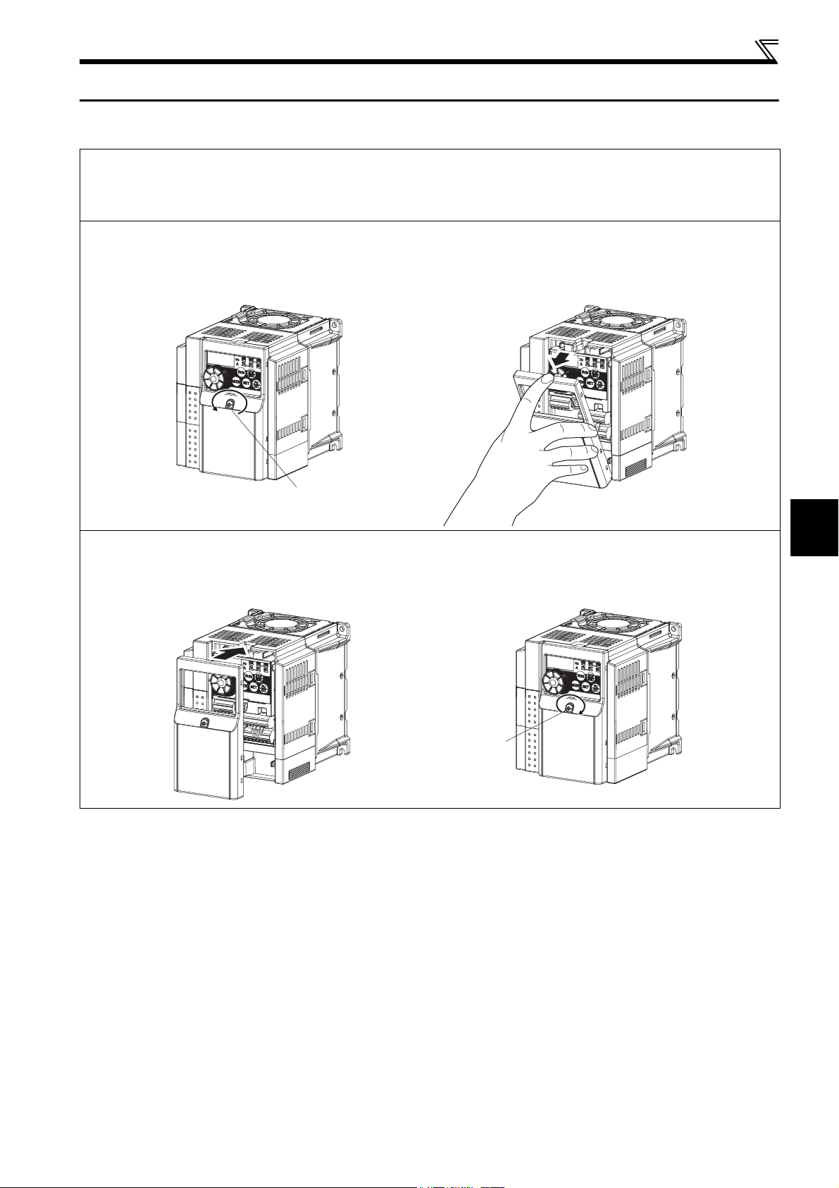
1.3 Removal and reinstallation of the cover
1.3.1 Front cover
FR-D720-165 or less
FR-D740-080 or less
FR-D720S-008 to 100
Removal (Example of FR-D740-036)
1) Loosen the installation screws of the front cover. (The screws cannot be removed.)
2) Remove the front cover by pulling it like the direction of arrow.
1)
Installation screw
Reinstallation (Example of FR-D740-036)
1) Place the front cover in front of the inverter, and install it straight.
2) Tighten the installation screws on the front cover.
1) 2)
2)
1
OUTLINE
Installation screw
5
Page 17
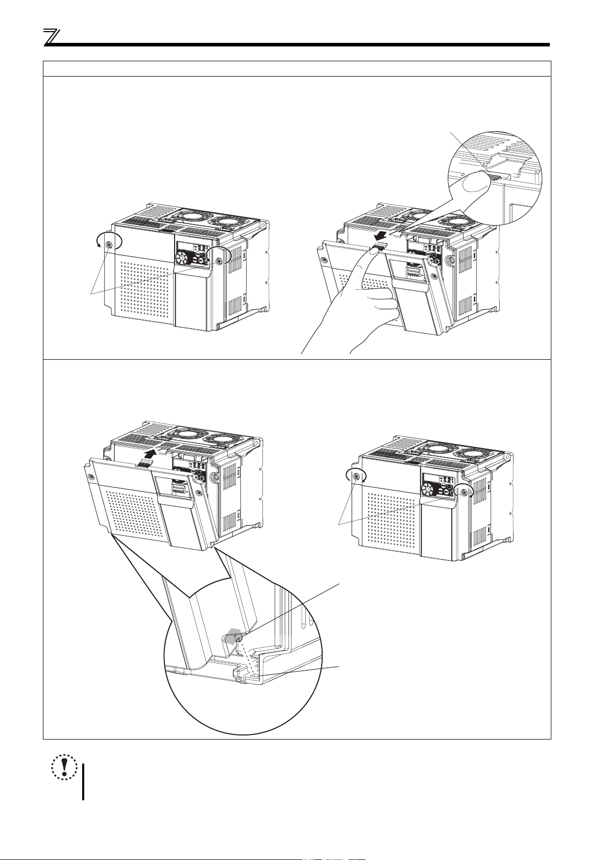
Removal and reinstallation of the cover
FR-D720-238, 318 and FR-D740-120, 160
Removal (Example of FR-D740-160)
1) Loosen the installation screws of the front cover. (The screws cannot be removed.)
2) Remove the front cover by pulling it like the direction of arrow with holding the installation hook on the front cover.
Installation hook
1) 2)
Installation
screw
Reinstallation (Example of FR-D740-160)
1) Insert the two fixed hooks on the lower side of the front cover into the sockets of the inverter.
2) Tighten the installation screws on the front cover.
1) 2)
Installation screw
Fixed hook
Socket of the inverter
NOTE
Fully make sure that the front cover has been reinstalled securely.
The same serial number is printed on the capacity plate of the front cover and the rating plate of the inverter. Since
these plates have the same serial numbers, always reinstall the removed cover onto the original inverter.
6
Page 18
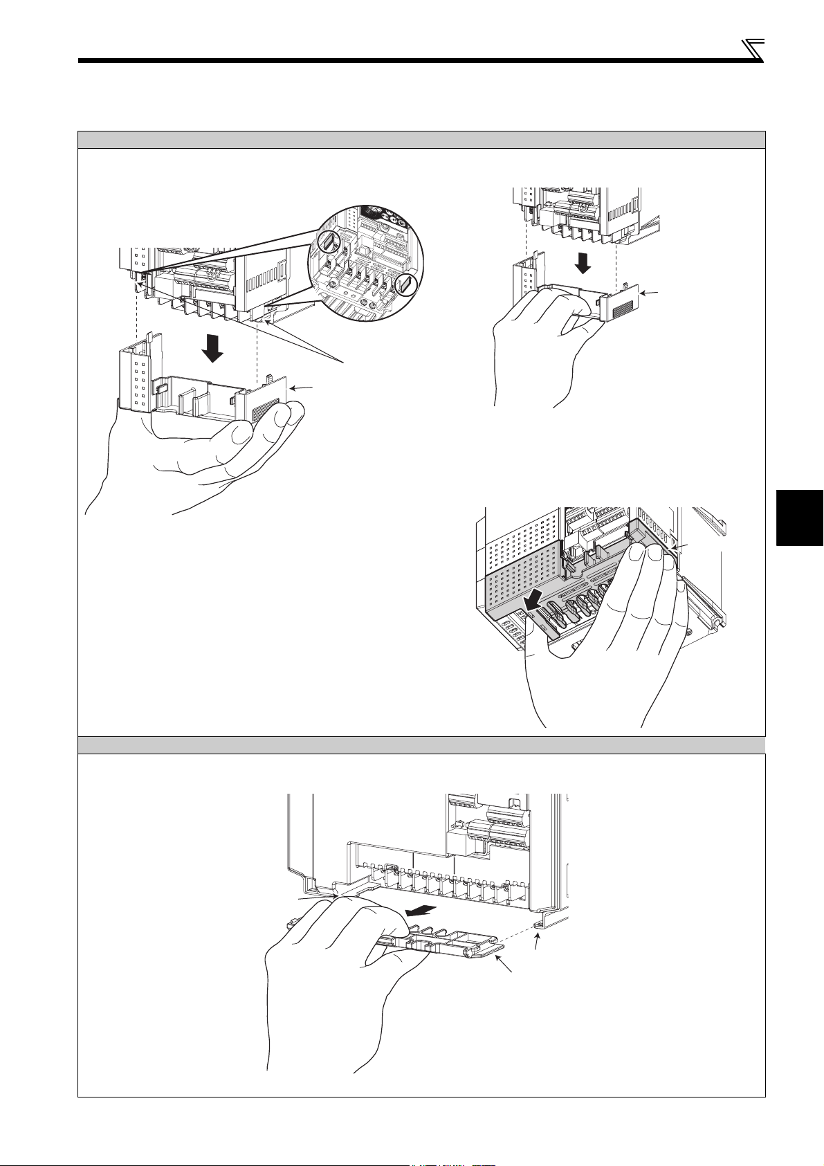
1.3.2 Wiring cover
r
r
r
Removal and reinstallation
FR-D720-165 or less and FR-D740-080 or less and FR-D720S-008 to 100
Hold the side of the wiring cover, and pull it downward for
removal.
To reinstall, fit the cover to the inverter along the guides.
Guide
Wiring cover
Example of FR-D740-036
Removal and reinstallation of the cover
Also pull the wiring cover downward with holding a
frontal part of the wiring cover.
Wiring cove
Example of FR-D740-036
See below diagram for wiring cover of FR-D720-165.
Hold the dent of the wiring cover (marked with an
arrow) with thumb and the side with other fingers and
pull downward for removal.
1
Wiring cove
FR-D720-238, 318 and FR-D740-120, 160
The cover can be removed easily by pulling it toward you.
To reinstall, fit the cover to the inverter along the guides.
Guide
OUTLINE
Guide
Wiring cove
Example of FR-D740-160
7
Page 19

Installation of the inverter and enclosure design
1.4 Installation of the inverter and enclosure design
When an inverter panel is to be designed and manufactured, heat generated by contained equipment, etc., the environment of
an operating place, and others must be fully considered to determine the panel structure, size and equipment layout. The
inverter unit uses many semiconductor devices. To ensure higher reliability and long period of operation, operate the inverter
in the ambient environment that completely satisfies the equipment specifications.
1.4.1 Inverter installation environment
As the inverter installation environment should satisfy the standard specifications indicated in the following table, operation in
any place that does not meet these conditions not only deteriorates the performance and life of the inverter, but also causes a
failure. Refer to the following points and take adequate measures.
Environmental standard specifications of inverter
Item Description
Surrounding air
temperature
Ambient humidity 90%RH maximum (non-condensing)
Atmosphere Free from corrosive and explosive gases, free from dust and dirt
Maximum altitude 1,000m (3280.80 feet) or less
Vibration
-10 to +50
5.9m/s
(1) Temperature
The permissible surrounding air temperature of the inverter is between -10 and +50°C
inverter within this temperature range. Operation outside this range will considerably shorten the service lives of the
semiconductors, parts, capacitors and others. Take the following measures so that the surrounding air temperature of the
inverter falls within the specified range.
1) Measures against high temperature
Use a forced ventilation system or similar cooling system. (Refer to page 10)
Install the panel in an air-conditioned electrical chamber.
Block direct sunlight.
Provide a shield or similar plate to avoid direct exposure to the radiated heat and wind of a heat source.
Ventilate the area around the panel well.
°C (14°F to 122°F)(non-freezing)
2
or less
(14°F to 122°F). Always operate the
2) Measures against low temperature
Provide a space heater in the enclosure.
Do not power off the inverter. (Keep the start signal of the inverter off.)
3) Sudden temperature changes
Select an installation place where temperature does not change suddenly.
Avoid installing the inverter near the air outlet of an air conditioner.
If temperature changes are caused by opening/closing of a door, install the inverter away from the door.
(2) Humidity
Normally operate the inverter within the 45 to 90% range of the ambient humidity. Too high humidity will pose problems of
reduced insulation and metal corrosion. On the other hand, too low humidity may produce a spatial electrical breakdown. The
insulation distance specified in JEM1103 "Control Equipment Insulator" is defined as humidity 45 to 85%.
1) Measures against high humidity
Make the panel enclosed, and provide it with a hygroscopic agent.
Take dry air into the enclosure from outside.
Provide a space heater in the enclosure.
2) Measures against low humidity
What is important in fitting or inspection of the unit in this status is to discharge your body (static electricity)
beforehand and keep your body from contact with the parts and patterns, besides blowing air of proper humidity into
the enclosure from outside.
3) Measures against condensation
Condensation may occur if frequent operation stops change the in-enclosure temperature suddenly or if the outside-
air temperature changes suddenly.
Condensation causes such faults as reduced insulation and corrosion.
Take the measures against high humidity in 1).
Do not power off the inverter. (Keep the start signal of the inverter off.)
8
Page 20

Installation of the inverter and enclosure design
(3) Dust, dirt, oil mist
Dust and dirt will cause such faults as poor contact of contact points, reduced insulation or reduced cooling effect due to
moisture absorption of accumulated dust and dirt, and in-enclosure temperature rise due to clogged filter. In the atmosphere
where conductive powder floats, dust and dirt will cause such faults as malfunction, deteriorated insulation and short circuit in
a short time.
Since oil mist will cause similar conditions, it is necessary to take adequate measures.
Countermeasures
Place in a totally enclosed enclosure.
Take measures if the in-enclosure temperature rises. (Refer to page 10)
Purge air.
Pump clean air from outside to make the in-enclosure pressure higher than the outside-air pressure.
(4) Corrosive gas, salt damage
If the inverter is exposed to corrosive gas or to salt near a beach, the printed board patterns and parts will corrode or the
relays and switches will result in poor contact.
In such places, take the measures given in Section 3.
(5) Explosive, flammable gases
As the inverter is non-explosion proof, it must be contained in an explosion proof enclosure. In places where explosion may be
caused by explosive gas, dust or dirt, an enclosure cannot be used unless it structurally complies with the guidelines and has
passed the specified tests. This makes the enclosure itself expensive (including the test charges). The best way is to avoid
installation in such places and install the inverter in a non-hazardous place.
(6) Highland
Use the inverter at the altitude of within 1000m (3280.80 feet). If it is used at a higher place, it is likely that thin air will reduce
the cooling effect and low air pressure will deteriorate dielectric strength.
Maximum 1000m (3280.80feet) above sea level for standard operation. After that derate by 3% for every extra 500m
(1640.40feet) up to 2500m (8202feet) (91%).
(7) Vibration, impact
The vibration resistance of the inverter is up to 5.9m/s2 at 10 to 55Hz frequency and 1mm amplitude. Vibration or impact, if
less than the specified value, applied for a long time may make the mechanism loose or cause poor contact to the connectors.
Especially when impact is imposed repeatedly, caution must be taken as the part pins are likely to break.
Countermeasures
Provide the panel with rubber vibration isolators.
Strengthen the structure to prevent the enclosure from resonance.
Install the enclosure away from sources of vibration.
1
OUTLINE
9
Page 21
Installation of the inverter and enclosure design
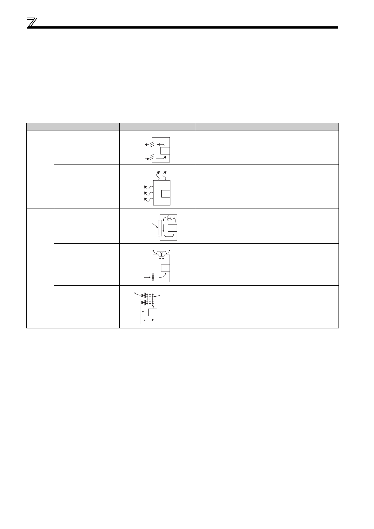
1.4.2 Cooling system types for inverter enclosure
From the enclosure that contains the inverter, the heat of the inverter and other equipment (transformers, lamps, resistors,
etc.) and the incoming heat such as direct sunlight must be dissipated to keep the in-enclosure temperature lower than the
permissible temperatures of the in-panel equipment including the inverter.
The cooling systems are classified as follows in terms of the cooling calculation method.
1) Cooling by natural heat dissipation from the enclosure surface (totally enclosed type)
2) Cooling by heat sink (aluminum fin, etc.)
3) Cooling by ventilation (forced ventilation type, pipe ventilation type)
4) Cooling by heat exchanger or cooler (heat pipe, cooler, etc.)
Cooling System Enclosure Structure Comment
Natural
cooling
Forced
cooling
Natural ventilation
(enclosed, open type)
Natural ventilation
(totally enclosed type)
Heatsink cooling
Forced ventilation
Heat pipe Totally enclosed type for enclosure downsizing.
Heatsink
INV
INV
INV
INV
Heat pipe
INV
Low in cost and generally used, but the enclosure size
increases as the inverter capacity increases. For relatively
small capacities.
Being a totally enclosed type, the most appropriate for hostile
environment having dust, dirt, oil mist, etc. The enclosure size
increases depending on the inverter capacity.
Having restrictions on the heatsink mounting position and
area, and designed for relative small capacities.
For general indoor installation. Appropriate for enclosure
downsizing and cost reduction, and often used.
10
Page 22
Installation of the inverter and enclosure design
1.4.3 Inverter placement
(1) Installation of the inverter
Enclosure surface mounting
Remove the front cover and wiring cover to fix the inverter to the surface.
FR-D720-008 to 042
FR-D720S-008 to 042
Front cover
FR-D720-070 or more
FR-D740-012 or more
FR-D720S-070, 100
Front cover
Wiring cover
Wiring cover
NOTE
When encasing multiple inverters, install them in parallel as a
cooling measure.
Install the inverter vertically.
Refer to the clearances below.
Vertical
(2) Clearances around inverter
To ensure ease of heat dissipation and maintenance, leave at least the shown clearances around the inverter. At least the
following clearances are required under the inverter as a wiring space, and above the inverter as a heat dissipation space.
Surrounding air temperature and humidity
Measurement
position
5cm
(1.97inches)
Measurement
Inverter
position
5cm
(1.97inches)
5cm (1.97inches)
Temperature: -10 C to +50 C
(14 F to 122 F)
Humidity: 90% RH maximum
Leave enough clearances and take
cooling measures.
Clearances (front)
10cm
(3.94inches)
1cm
(0.39inches)
* When using the inverters at the surrounding air
temperature of 40 C (
be installed without any clearance between them
0inch)
(0cm (
When surrounding air temperature exceeds 40 C
104 F)
, clearances between the inverters should be
(
(0.39inches)
1cm
for the FR-D720-238 or more and FR-D740-120 or
more).
or more*
clearance).
or more (5cm
or more
1cm
(0.39inches)
or more*
10cm
(3.94inches)
or more
104 F)
or less, the inverters can
(1.97inches)
or more
Clearances (side)
1cm
(0.39
Inverter
inches)
or more
*
* 5cm
(1.97inches)
the FR-D720-238 or more
and FR-D740-120 or more
or more for
1
OUTLINE
(3) Inverter mounting orientation
Mount the inverter on a wall as specified. Do not mount it horizontally or any other way.
(4) Above inverter
Heat is blown up from inside the inverter by the small fan built in the unit. Any equipment placed above the inverter should be
heat resistant.
11
Page 23
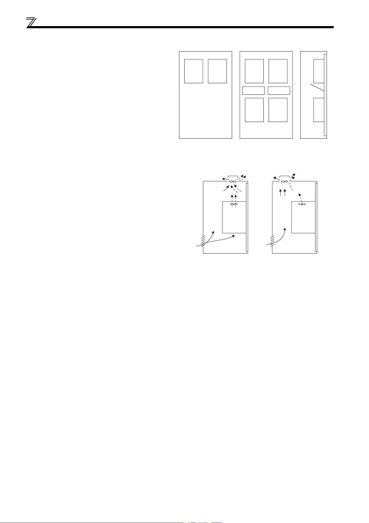
Installation of the inverter and enclosure design
(5) Arrangement of multiple inverters
When multiple inverters are placed in the same
enclosure, generally arrange them horizontally as shown
in the right figure (a). When it is inevitable to arrange
them vertically to minimize space, take such measures as
to provide guides since heat from the bottom inverters
can increase the temperatures in the top inverters,
causing inverter failures.
When mounting multiple inverters, fully take caution not
to make the surrounding air temperature of the inverter
higher than the permissible value by providing ventilation
and increasing the enclosure size.
(6) Arrangement of ventilation fan and inverter
Heat generated in the inverter is blown up from the bottom of
the unit as warm air by the cooling fan. When installing a
ventilation fan for that heat, determine the place of ventilation
fan installation after fully considering an air flow. (Air passes
through areas of low resistance. Make an airway and airflow
plates to expose the inverter to cool air.)
(a) Horizontal arrangement
InverterInverter
Enclosure Enclosure
Arrangement of multiple inverters
Inverter Inverter
Inverter
Guide Guide
Inverter
Inverter
Inverter
(b) Vertical arrangement
Guide
<Good example> <Bad example>
Arrangement of ventilation fan and inverter
12
Page 24

2 WIRING
This chapter describes the basic "WIRING" for use of this
product.
Always read the instructions before using the equipment
2.1 Wiring............................................................................................. 14
2.2 Main circuit terminal specifications............................................ 15
2.3 Control circuit specifications ...................................................... 20
2.4 Connection of stand-alone option unit ....................................... 31
1
2
3
4
5
13
6
7
Page 25
Wiring
2.1 Wiring
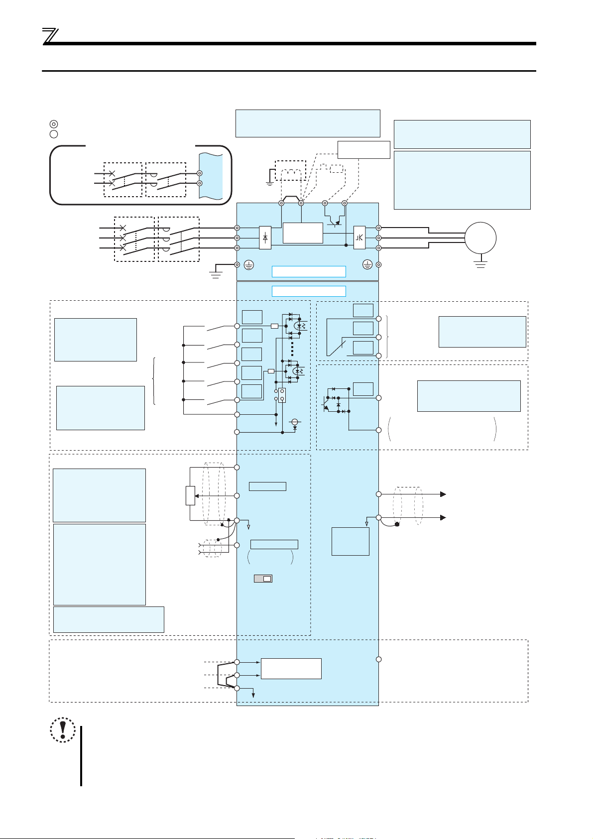
2.1.1 Terminal connection diagram
Sink logic
Main circuit terminal
Control circuit terminal
Single-phase power input
MCCB MC
Single-phase
AC power
supply
MCCB MC
Three-phase
AC power
supply
Earth
(Ground)
Control input signals (No voltage input allowed)
Terminal functions vary
with the input terminal
assignment (Pr. 178 to
Pr. 182)
Multi-speed selection
*2 When using terminals PC-
SD as a 24VDC power
supply, take care not to
short across terminals
PC-SD.
(Common for external power supply transistor)
Forward
rotation start
Reverse
rotation start
High
speed
Middle
speed
Low
speed
Contact input common
24VDC power supply
R/L1
S/L2
*1. DC reactor (FR-HEL)
When connecting a DC reactor, remove the
jumper across P1-P/+
Earth
(Ground)
Jumper
R/L1
S/L2
T/L3
*1
P1 P/+
Inrush current
limit circuit
R
*7
PR
*6
Main circuit
Control circuit
STF
STR
RH
RM
PC
RL
SD
*2
SOURCE
SINK
24V
N/-
Brake unit
(Option)
C
B
A
RUN
SE
*6 A brake transistor is not built-in to the
FR-D720-008, 014 and FR-D720S-008,
014.
*7 Brake resistor (FR-ABR, MRS type, MYS
type)
Install a thermal relay to prevent an
overheat and burnout of the brake resistor.
(The brake resistor can not be connected
to the FR-D720-008, 014 and FR-D720S008, 014.)
U
V
W
Relay output
Terminal functions vary
Relay output
(Fault output)
by Pr. 192 A,B,C terminal
function selection
Open collector output
Terminal functions vary by
Running
Pr. 190 RUN terminal function
selection
Open collector output common
Sink/source common
Motor
IM
Earth (Ground)
Frequency setting signals (Analog)
*3 Terminal input specifications
can be changed by analog
input specifications
switchover (Pr. 73).
Terminal 10 and terminal 2
are used as PTC input
terminal (Pr. 561).
*4 Terminal input
specifications can be
changed by analog input
specifications switchover
(Pr. 267). Set the
voltage/current input
switch in the "V" position
to select voltage input (0
to 5V/0 to10V) and "I"
(initial value) to select
current input (4 to 20mA).
*5 It is recommended to use 2W1kΩ
when the frequency setting signal
is changed frequently.
Frequency
setting
potentiometer
1/2W1kΩ
Safety stop signal
Output shutoff (Line 1)
Output shutoff (Line 2)
Common terminal
*5
Terminal 4
input
(Current
input)
3
2
1
(+)
(-)
Shorting
10(+5V)
2 0 to 5VDC
5(Analog common)
4 4 to 20mADC
VI
Voltage/current
input switch
S1
wire
S2
SC
(0 to 10VDC)
0 to 5VDC
0 to 10VDC
Output shutoff
circuit
*3
AM
5
(+)
Analog signal output
(-)
PU
connector
*4
*4
SO
Safety monitor output *8
For manufacturer setting
*8 Common terminal of
terminal SO is terminal SC.
(Connected to terminal SD
inside of the inverter.)
NOTE
To prevent a malfunction caused by noise, separate the signal cables more than 10cm (3.94inches) from the power
cables. Also separate the main circuit wire of the input side and the output side.
After wiring, wire offcuts must not be left in the inverter.
Wire offcuts can cause an alarm, failure or malfunction. Always keep the inverter clean. When drilling mounting holes
in an enclosure etc., take care not to allow chips and other foreign matter to enter the inverter.
The output of the single-phase power input specification is three-phase 200V.
(0 to 10VDC)
14
Page 26
Main circuit terminal specifications
r
2.2 Main circuit terminal specifications
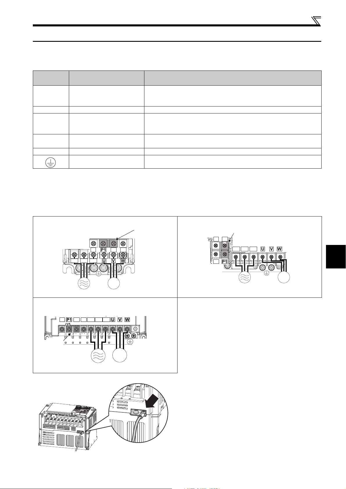
2.2.1 Specification of main circuit terminal
Ter mina l
Symbol
R/L1,
S/L2,
T/L3 *
U, V, W Inverter output Connect a three-phase squirrel-cage motor.
P/+, PR Brake resistor connection
P/+, N/- Brake unit connection
P/+, P1 DC reactor connection Remove the jumper across terminals P/+ and P1 and connect a DC reactor.
* When using single-phase power input, terminals are R/L1 and S/L2.
AC power input
Earth (Ground) For earthing (grounding) the inverter chassis. Must be earthed (grounded).
Terminal Name Description
Connect to the commercial power supply.
Keep these terminals open when using the high power factor converter (FR-HC) or
power regeneration common converter (FR-CV).
Connect a brake resistor (FR-ABR, MRS type, MYS type) across terminals P/+ and PR.
(The brake resistor can not be connected to the FR-D720-008 and 014 and FR-
D720S-008 and 014.)
Connect the brake unit (FR-BU2), power regeneration common converter (FR-CV)
or high power factor converter (FR-HC).
2.2.2 Terminal arrangement of the main circuit terminal, power supply and the motor wiring
Three-phase 200V class
FR-D720-008 to 042 FR-D720-070 to 165
Screw size (M3.5)
N/-
R/L1 S/L2 T/L3
Jumpe
N/-
P/+ PR
PR
P/+
R/L1 S/L2 T/L3
Jumper
Screw size (M4)
2
Screw size
(M4)
IM
Motor
FR-D720-238, 318
Screw size (M5)
N/-
Jumper
P/+ PR
Screw size
(M3.5)
R/L1 S/L2 T/L3
MotorPower supply
IM
Power supply
Screw size (M5)
IM
Power supply Motor
* For wiring to earth (ground) terminals of FR-D720-238 and 318, use the earthing cable wiring space (marked with an arrow) to route the wires.
WIRING
15
Page 27
Main circuit terminal specifications
r
Three-phase 400V class
FR-D740-012 to 080 FR-D740-120, 160
N/-
P/+
R/L1 S/L2 T/L3
Jumper
Screw size (M4)
Jumper
N/-
PR
Screw size
(M4)
IM
MotorPower supply
Single-phase 200V class
FR-D720S-008 to 042 FR-D720S-070, 100
Screw size (M3.5)
N/-
R/L1 S/L2
Screw size
(M3.5)
P/+ PR
IM
MotorPower supply
Jumpe
N/-
PR
NOTE
Make sure the power cables are connected to the R/L1, S/L2, T/L3. (Phase need not be matched.) Never connect the
power cable to the U, V, W of the inverter. Doing so will damage the inverter.
Connect the motor to U, V, W. Turning on the forward rotation switch (signal) at this time rotates the motor
counterclockwise when viewed from the load shaft.
P/+
R/L1 S/L2 T/L3
P/+
PR
Jumper
Screw size (M4)
R/L1 S/L2
Screw size (M4)
IM
MotorPower supply
Screw size
(M4)
Screw size
(M4)
IM
MotorPower supply
16
Page 28
Main circuit terminal specifications
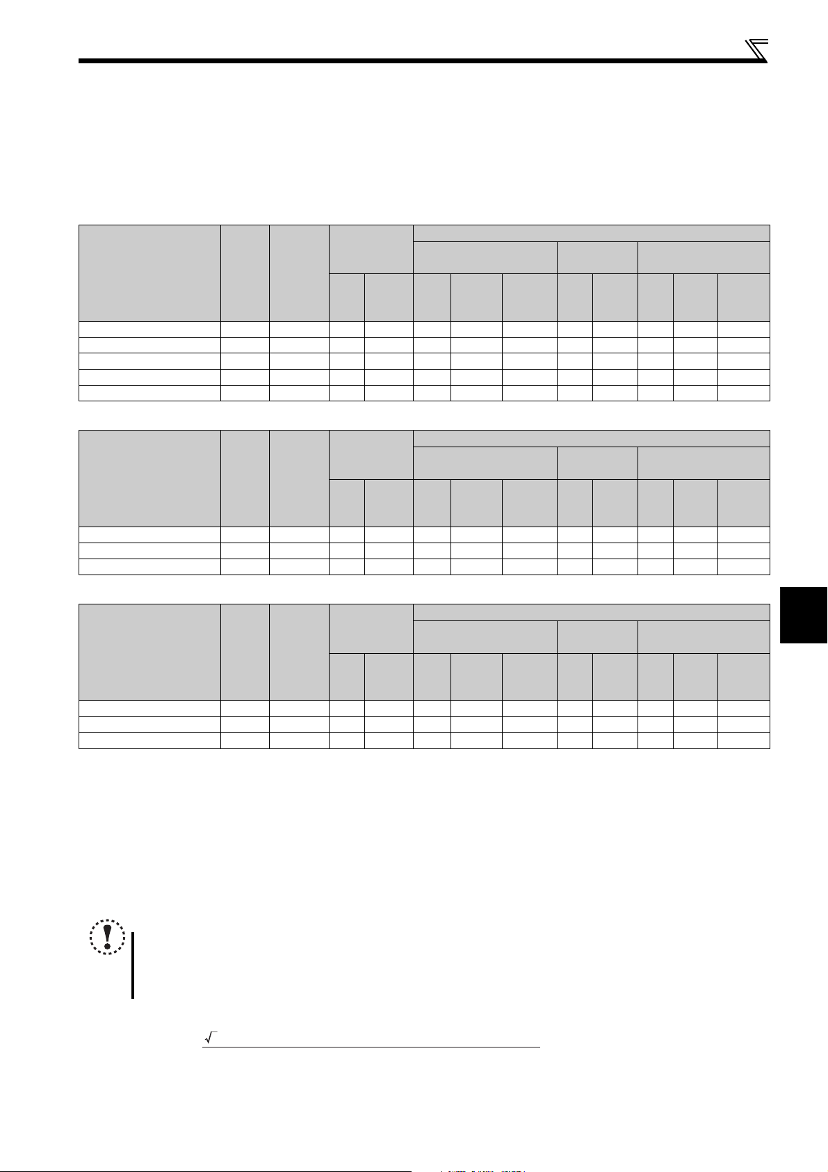
2.2.3 Cables and wiring length
(1) Applied wire size
Select the recommended cable size to ensure that a voltage drop will be 2% max.
If the wiring distance is long between the inverter and motor, a main circuit cable voltage drop will cause the motor torque to
decrease especially at the output of a low frequency.
The following table indicates a selection example for the wiring length of 20m (65.61feet).
Three-phase 200V class (when input power supply is 220V)
Crimping
Applicable Inverter
Model
FR-D720-008 to 042 M3.5 1.2 2-3.5 2-3.5 2 2 2 14 14 2.5 2.5 2.5
FR-D720-070, 100 M4 1.5 2-4 2-4 2 2 2 14 14 2.5 2.5 2.5
FR-D720-165 M4 1.5 5.5-4 5.5-4 3.5 3.5 3.5 12 12 4 4 4
FR-D720-238 M5 2.5 5.5-5 5.5-5 5.5 5.5 5.5 10 10 6 6 6
FR-D720-318 M5 2.5 14-5 8-5 14 8 5.5 6 8 16 10 6
Ter minal
Screw
Size ∗4
Tightening
Torqu e
·
m
N
Ter minal
R/L1
S/L2
T/L3
U, V, W
HIV Cables, etc. (mm2) ∗1
R/L1
S/L2
T/L3
U, V, W
Earth
(ground)
cable
Three-phase 400V class (when input power supply is 440V)
Crimping
Applicable Inverter
Model
FR-D740-012 to 080 M4 1.5 2-4 2-4 2 2 2 14 14 2.5 2.5 2.5
FR-D740-120 M4 1.5 5.5-4 2-4 3.5 2 3.5 12 14 4 2.5 4
FR-D740-160 M4 1.5 5.5-4 5.5-4 3.5 3.5 3.5 12 12 4 4 4
Ter minal
Screw
Size ∗4
Tightening
Torqu e
·
m
N
Ter minal
R/L1
S/L2
T/L3
U, V, W
HIV Cables, etc. (mm2) ∗1
R/L1
S/L2
T/L3
U, V, W
Earth
(ground)
cable
Cable Size
AWG ∗2
R/L1
U, V, W
S/L2
T/L3
Cable Size
AWG ∗2
R/L1
U, V, W
S/L2
T/L3
PVC Cables, etc. (mm2)
R/L1
S/L2
T/L3
PVC Cables, etc. (mm2)
R/L1
S/L2
T/L3
∗3
U, V, W
∗3
U, V, W
Earth
(ground)
cable
Earth
(ground)
cable
Single-phase 200V class (when input power supply is 220V)
Crimping
Applicable Inverter
Model
FR-D720S-008 to 042 M3.5 1.2 2-3.5 2-3.5 2 2 2 14 14 2.5 2.5 2.5
FR-D720S-070 M4 1.5 2-4 2-4 2 2 2 14 14 2.5 2.5 2.5
FR-D720S-100 M4 1.5 5.5-4 2-4 3.5 2 3.5 12 14 4 2.5 4
∗1 The cable size is that of the cable (HIV cable (600V class 2 vinyl-insulated cable) etc.) with continuous maximum permissible temperature of 75°C (167°F).
Assumes that the surrounding air temperature is 50°C (122°F) or less and the wiring distance is 20m (65.61feet) or less.
∗2 The recommended cable size is that of the cable (THHW cable) with continuous maximum permissible temperature of 75°C (167°F). Assumes that the
surrounding air temperature is 40°C (104°F) or less and the wiring distance is 20m (65.61feet) or less.
(Selection example for use mainly in the United States.)
∗3 The recommended cable size is that of the cable (THHW cable) with continuous maximum permissible temperature of 70°C (158°F). Assumes that the
surrounding air temperature is 40°C (104°F) or less and the wiring distance is 20m (65.61feet) or less.
(Selection example for use mainly in Europe.)
∗4 The terminal screw size indicates the terminal size for R/L1, S/L2, T/L3, U, V, W, PR, P/+, N/-, P1 and a screw for earthing (grounding).
For single-phase power input, the terminal screw size indicates the size of terminal screw for R/L1, S/L2, U, V, W, PR, P/+, N/-, P1 and a screw for earthing (grounding).
Ter minal
Screw
Size ∗4
Tightening
Torqu e
·
m
N
Ter minal
R/L1
S/L2
U, V, W
HIV Cables, etc. (mm2) ∗1
R/L1
S/L2
U, V, W
Earth
(ground)
cable
Cable Size
AWG ∗2
R/L1
U, V, W
S/L2
PVC Cables, etc. (mm2)
R/L1
S/L2
∗3
U, V, W
Earth
(ground)
cable
NOTE
Tighten the terminal screw to the specified torque. A screw that has been tightened too loosely can cause a short
circuit or malfunction. A screw that has been tightened too tightly can cause a short circuit or malfunction due to the
unit breakage.
Use crimping terminals with insulation sleeve to wire the power supply and motor.
2
WIRING
The line voltage drop can be calculated by the following formula:
line voltage drop [V]=
3 × wire resistance[mΩ/m] × wiring distance[m] × current[A]
1000
Use a larger diameter cable when the wiring distance is long or when it is desired to decrease the voltage drop (torque
reduction) in the low speed range.
17
Page 29
Main circuit terminal specifications
(2) Earthing (Grounding) precautions
Always earth (ground) the motor and inverter.
1) Purpose of earthing (grounding)
Generally, an electrical apparatus has an earth (ground) terminal, which must be connected to the ground before use.
An electrical circuit is usually insulated by an insulating material and encased. However, it is impossible to manufacture
an insulating material that can shut off a leakage current completely, and actually, a slight current flow into the case.
The purpose of earthing (grounding) the case of an electrical apparatus is to prevent operator from getting an electric
shock from this leakage current when touching it.
To avoid the influence of external noises, this earthing (grounding) is important to audio equipment, sensors, computers
and other apparatuses that handle low-level signals or operate very fast.
2) Earthing (grounding) methods and earthing (grounding) work
As described previously, earthing (grounding) is roughly classified into an electrical shock prevention type and a noise-
affected malfunction prevention type. Therefore, these two types should be discriminated clearly, and the following
work must be done to prevent the leakage current having the inverter's high frequency components from entering the
malfunction prevention type earthing (grounding):
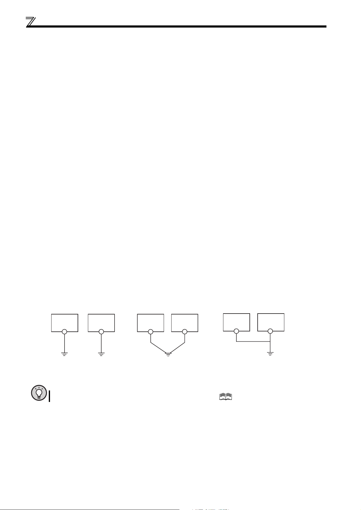
(a)Where possible, use independent earthing (grounding) for the inverter. If independent earthing (grounding) (I) is
impossible, use joint earthing (grounding) (II) where the inverter is connected with the other equipment at an
earthing (grounding) point. Joint earthing (grounding) as in (III) must be avoided as the inverter is connected with the
other equipment by a common earth (ground) cable.
Also a leakage current including many high frequency components flows in the earth (ground) cables of the inverter
and inverter-driven motor. Therefore, they must use the independent earthing (grounding) method and be separated
from the earthing (grounding) of equipment sensitive to the aforementioned noises.
In a tall building, it will be a good policy to use the noise malfunction prevention type earthing (grounding) with steel
frames and carry out electric shock prevention type earthing (grounding) in the independent earthing (grounding)
method.
(b)This inverter must be earthed (grounded). Earthing (Grounding) must conform to the requirements of national and
local safety regulations and electrical codes. (NEC section 250, IEC 536 class 1 and other applicable standards).
Use an neutral-point earthed (grounded) power supply for 400V class inverter in compliance with EN standard.
(c)Use the thickest possible earth (ground) cable. The earth (ground) cable should be of not less than the size indicated
in the table on the previous page 17.
(d)The earthing (grounding) point should be as near as possible to the inverter, and the earth (ground) cable length
should be as short as possible.
(e)Run the earth (ground) cable as far away as possible from the I/O wiring of equipment sensitive to noises and run
them in parallel in the minimum distance.
18
Inverter
(I)Independent earthing.......Best
Other
equipment
Inverter
(II)Common earthing.......Good
Other
equipment
Inverter
(III)Common earthing.......Not allowed
Other
equipment
POINT
To be compliant with the European Directive (Low Voltage Directive), refer to the Installation Guideline.
Page 30
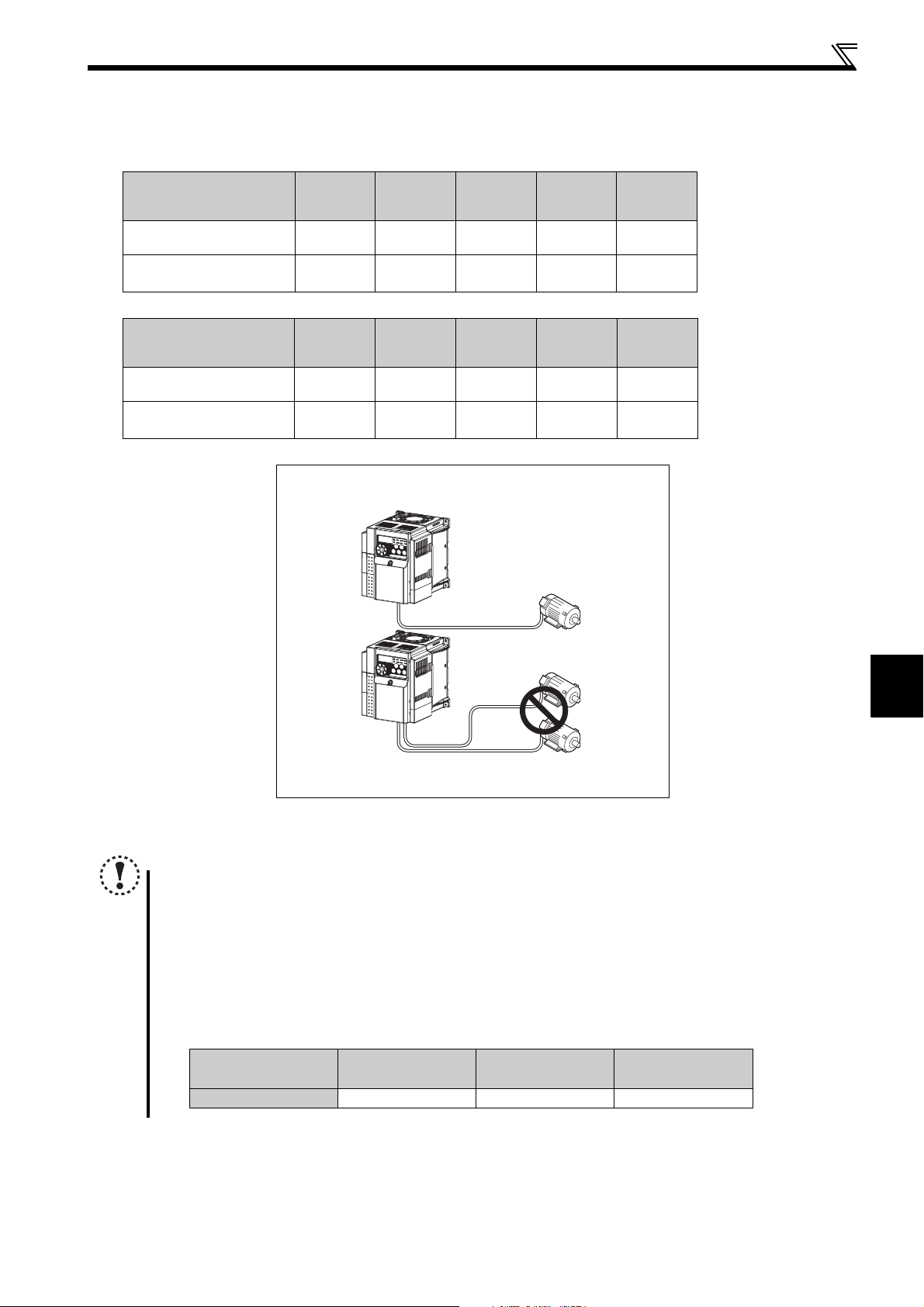
Main circuit terminal specifications
(3) Total wiring length
The overall wiring length for connection of a single motor or multiple motors should be within the value in the table
below.
200V class
Pr. 72 PWM frequency
selection Setting
(carrier frequency)
1 (1kHz) or less
2 to15
(2kHz to 14.5kHz)
400V class
Pr. 72 PWM frequency
selection Setting
(carrier frequency)
1 (1kHz) or less
2 to15
(2kHz to 14.5kHz)
008 014 025 042 070 or More
200m
(656.19feet)
30m
(98.42feet)
012 022 036 050
200m
(656.19feet)
30m
(98.42feet)
Total wiring length (FR-D720-070 or more, FR-D720S-070 or more,
FR-D740-080 or more)
200m
(656.19feet)
100m
(328.08feet)
200m
(656.19feet)
100m
(328.08feet)
300m
(984.25feet)
200m
(656.19feet)
300m
(984.25feet)
200m
(656.19feet)
500m
(1640.42feet)
300m
(984.25feet)
500m
(1640.42feet)
300m
(984.25feet)
500m
(1640.42feet)
500m
(1640.42feet)
or More
500m
(1640.42feet)
500m
(1640.42feet)
080
500m
(1640.42feet)
or less
300m
(984.25feet)
300m
(984.25feet)
300m(984.25feet) + 300m(984.25feet)
= 600m(1968.50feet)
When driving a 400V class motor by the inverter, surge voltages attributable to the wiring constants may occur at the
motor terminals, deteriorating the insulation of the motor.(Refer to page 83)
NOTE
Especially for long-distance wiring, the inverter may be affected by a charging current caused by the stray
capacitances of the wiring, leading to a malfunction of the overcurrent protective function, fast response current limit
function, or stall prevention function or a malfunction or fault of the equipment connected on the inverter output side.
If malfunction of fast-response current limit function occurs, disable this function. If malfunction of stall prevention
function occurs, increase the stall level. (Refer to page 79 for Pr. 22 Stall prevention operation level and Pr. 156 Stall prevention
operation selection )
Refer to page 148 for details of Pr. 72 PWM frequency selection. Refer to the manual of the option for details of surge
voltage suppression filter (FR-ASF-H/FR-BMF-H).
When using the automatic restart after instantaneous power failure function with wiring length exceeding below,
select without frequency search (Pr. 162 = "1, 11"). (Refer to page 136)
Motor capacity
(kW(HP))
Wiring length
0.1K(1/8) 0.2K(1/4) 0.4K(1/2) or more
20m (65.61feet) 50m (164.04feet) 100m (323.08feet)
2
WIRING
19
Page 31

Control circuit specifications
2.3 Control circuit specifications
2.3.1 Control circuit terminal
indicates that terminal functions can be selected using Pr. 178 to Pr. 182, Pr. 190, Pr. 192 (I/O terminal function selection).
(Refer to page 113).
(1) Input signal
Term inal
Typ e
Symbol
STF Forward rotation start
STR Reverse rotation start
RH,
RM,
RL
SD
Contact input
PC
10
2
4
Frequency setting
Terminal Name Description Rated Specifications
Turn on the STF signal to
start forward rotation and
turn it off to stop.
Turn on the STR signal to
start reverse rotation and
turn it off to stop.
Multi-speed selection
Contact input common
(sink) (initial setting)
External transistor
common (source)
24VDC power supply
common
External transistor
common (sink)
(initial setting)
Contact input common
(source)
24VDC power supply Can be used as 24VDC 0.1A power supply.
Frequency setting power
supply
Frequency setting
(voltage)
Frequency setting
(current)
Multi-speed can be selected according to the
combination of RH, RM and RL signals.
Common terminal for contact input terminal (sink
logic).
When connecting the transistor output (open collector
output), such as a programmable controller, when
source logic is selected, connect the external power
supply common for transistor output to this terminal to
prevent a malfunction caused by undesirable currents.
Common output terminal for 24VDC 0.1A power
supply (PC terminal).
Isolated from terminals 5 and SE.
When connecting the transistor output (open collector
output), such as a programmable controller, when sink
logic is selected, connect the external power supply
common for transistor output to this terminal to prevent
a malfunction caused by undesirable currents.
Common terminal for contact input terminal (source
logic).
Used as power supply when connecting potentiometer
for frequency setting (speed setting) from outside of
the inverter. (Refer to Pr. 73 Analog input selection.)
Inputting 0 to 5VDC (or 0 to 10V) provides the maximum
output frequency at 5V (10V) and makes input and output
proportional. Use
5VDC input (initial setting) and 0 to 10VDC.
Inputting 4 to 20mADC (or 0 to 5V, 0 to 10V) provides
the maximum output frequency at 20mA and makes
input and output proportional. This input signal is valid
only when the AU signal is on (terminal 2 input is
invalid). Use Pr. 267 to switch from among input 4 to
20mA (initial setting), 0 to 5VDC and 0 to 10VDC. Set
the voltage/current input switch in the "V" position to
select voltage input (0 to 5V/0 to 10V).
Pr. 73
When the STF and STR
signals are turned on
simultaneously, the stop
command is given.
to switch between input 0 to
Input resistance 4.7kΩ
Voltage when contacts are
open
21 to 26VDC
When contacts are shortcircuited
4 to 6mADC
——
Power supply voltage range
22 to 26.5VDC
permissible load current
100mA
5.0V ± 0.2VDC
permissible load current
10mA
Input resistance10kΩ ± 1kΩ
Permissible maximum
voltage 20VDC
Current input:
Input resistance 233Ω ± 5Ω
Maximum permissible
current 30mA
Voltage input:
Input resistance10kΩ ± 1kΩ
Permissible maximum
voltage 20VDC
Current input
(initial status)
Voltage input
Refer to
Page
117
89
23
150
150
150
20
5
10
2
PTC thermistor
Frequency setting
common
PTC thermistor input
Common terminal for frequency setting signal
(terminal 2 or 4) and analog output terminal AM. Do
not earth (ground).
For connecting PTC thermistor output.
When PTC thermistor protection is valid (Pr. 561 ≠
"9999"), terminal 2 is not available for frequency
setting.
——
Adaptive PTC thermistor
specification
Heat detection resistance :
500Ω to 30kΩ (Set by
Pr. 561
100
)
Page 32

NOTE
Set Pr. 267 and a voltage/current input switch correctly, then input analog signals in accordance with the settings.
Applying a voltage with voltage/current input switch in "I" position (current input is selected) or a current with switch in
"V" position (voltage input is selected) could cause component damage of the inverter or analog circuit of output
devices. (Refer to page 150 for details.)
(2) Output signal
Ter m inal
Typ e
Symbol
A, B, C
Relay
RUN Inverter running
Open collector
SE
AM Analog signal output
Analog
Terminal Name Description Rated Specifications
Relay output (fault
output)
Open collector output
common
Control circuit specifications
Reference
Page
1 changeover contact output indicates that the inverter
protective function has activated and the output stopped.
Fault: discontinuity across B-C (continuity across A-C),
Normal: continuity across B-C (discontinuity across A-C)
Switched low when the inverter output frequency is equal to
or higher than the starting frequency (initial value 0.5Hz).
Switched high during stop or DC injection brake operation.
(Low indicates that the open collector output transistor is on
(conducts).
High indicates that the transistor is off (does not conduct).)
Common terminal of terminal RUN. — —
Select one e.g. output
frequency from monitor
items. Not output during
inverter reset.
The output signal is
proportional to the magnitude
Output item:
Output frequency (initial
setting)
of the corresponding
monitoring item.
Contact capacity:230VAC
0.3A
(power factor =0.4)
30VDC 0.3A
Permissible load 24VDC
(maximum 27VDC) 0.1A
(a voltage drop is 3.4V
maximum when the signal
is on)
Output signal 0 to
10VDC
Permissible load current
1mA
(load impedance 10kΩ or
more)
Resolution 8 bit
119
119
128
(3) Communication
RS-485
Ter minal
Symbol
— PU connector
Terminal Name Description
With the PU connector, communication can be made through RS-485.
Conforming standard: EIA-485 (RS-485)
Transmission format: Multidrop link
Communication speed: 4800 to 38400bps
Overall length: 500m (1640.42feet)
Typ e
(4) Safety stop signal
Ter mina l
Symbol
S1
S2
SO For manufacturer setting
SC
Terminal Name Description
Inverter output shutoff
(Line 1)
Inverter output shutoff
(Line 2)
Output shutoff terminal
common
Inverter output is shutoff depending on shorting/opening between S1 and SC, S2 and SC.
At initial state, terminal S1 and S2 are shorted to terminal SC with a shorting wire.
When using the safety stop function, remove this shorting wire, and connect to a safety
relay module.
Common terminal for terminals S1, S2. Connected to terminal SD inside of the inverter.
Reference
Page
180
Reference
Page
—
2
WIRING
21
Page 33

Control circuit specifications
2.3.2 Changing the control logic
NOTE
Fully make sure that the front cover has been reinstalled securely.
The capacity plate is placed on the front cover and the rating plate is on the inverter. Since these plates have the
same serial numbers, always reinstall the removed cover onto the original inverter.
The sink-source logic change-over jumper connector must be fitted in only one of those positions. If it is fitted in both
positions at the same time, the inverter may be damaged.
The input signals are set to sink logic (SINK) when shipped from
the factory.
To change the control logic, the jumper connector above the
control terminal must be moved to the other position.
Change the jumper connector in the sink logic (SINK) position
to source logic (SOURCE) position using tweezers, a pair of
long-nose pliers etc. Change the jumper connector position
before switching power on.
22
Page 34

Control circuit specifications
(1) Sink logic type and source logic type
In sink logic, a signal switches on when a current flows from the corresponding signal input terminal.
Terminal SD is common to the contact input signals. Terminal SE is common to the open collector output signals.
In source logic, a signal switches on when a current flows into the corresponding signal input terminal.
Terminal PC is common to the contact input signals. Terminal SE is common to the open collector output signals.
Current flow concerning the input/output signal when sink logic is
selected
Sink logic
Current
STF
STR
SD
R
R
Sink
connector
Current flow concerning the input/output signal when source logic is
selected
Source logic
PC
Current
STF
R
STR
R
Source
connector
DC input (sink type)
Inverter
RUN
SE
24VDC
Current flow
<Example: QX40>
TB1
R
R
TB17
When using an external power supply for transistor output
Sink logic type
Use terminal PC as a common terminal, and perform
wiring as shown below. (Do not connect terminal SD of the
inverter with terminal 0V of the external power supply.
When using terminals PC-SD as a 24VDC power supply,
do not install an external power supply in parallel with the
inverter. Doing so may cause a malfunction in the inverter
due to undesirable currents.)
DC input (source type)
Inverter
RUN
SE
24VDC
Current flow
<Example: QX80>
TB1
R
TB18
R
Source logic type
Use terminal SD as a common terminal, and perform
wiring as shown below. (Do not connect terminal PC of the
inverter with terminal +24V of the external power supply.
When using terminals PC-SD as a 24VDC power supply,
do not install an external power supply in parallel with the
inverter. Doing so may cause a malfunction in the inverter
due to undesirable currents.)
2
WIRING
QY40P type transistor
output unit
Constant
voltage
circuit
TB1
TB2
TB17
TB18
24VDC
STF
STR
PC
SD
Current flow
Inverter
24VDC
(SD)
QY80 type transistor
output unit
Constant
voltage
circuit
Fuse
TB1
TB2
TB17
TB18
Current flow
PC
STF
STR
24VDC
SD
Inverter
24VDC
(SD)
23
Page 35

Control circuit specifications
2.3.3 Wiring of control circuit
(1) Standard control circuit terminal layout
Recommend wire size:
0.3mm
2
to 0.75mm
2
10 2 5 4
AM
RUN SE S1 S2 SCSO
CBA
SD
STF
PCSDRHRMRL
STR
(2) Wiring method
Wiring
Use a bar terminal and a wire with a sheath stripped off for the control circuit wiring. For a single wire, strip off the sheath of
the wire and apply directly.
Insert the bar terminal or the single wire into a socket of the terminal.
1) Strip off the sheath about the size below. If the length of the sheath peeled is too long, a short circuit may occur among
neighboring wires. If the length is too short, wires might come off.
Wire stripping size
Wire the stripped wire after twisting it to prevent it from
10mm
(0.39 inch)
becoming loose. In addition, do not solder it.
2) Crimp the bar terminal.
Insert wires to a bar terminal, and check that the wires come out for about 0 to 0.5 mm from a sleeve.
Wire
Shell
Sleeve
0 to 0.5mm (0.02 inch)
Check the condition of the bar terminal after crimping. Do not use a bar terminal of which the crimping is inappropriate, or
the face is damaged.
Unstranded
wires
Damaged
Crumpled tip
Wires are not inserted
into the shell
Introduced products on bar terminals :(as of Mar., 2008)
Wire Size (mm2)
0.3, 0.5 AI 0,5-10WH —
0.75 AI 0,75-10GY A 0,75-10
1 AI 1-10RD A1-10
1.25, 1.5 AI 1,5-10BK A1,5-10
0.75 (for two wires) AI-TWIN 2 x 0,75-10GY —
with insulation sleeve without insulation sleeve
Bar Terminal Model
Phoenix Contact Co.,Ltd.
Maker
Bar terminal crimping tool: CRIMPFOX ZA3 (Phoenix Contact Co., Ltd.)
24
Page 36

Control circuit specifications
r
r
3) Insert the wire into a socket.
When using a stranded wire without a bar terminal, push an open/close button all the way down with a flathead screw
driver, and insert the wire.
Open/close button
Flathead screwdrive
Note
When using a stranded wire without a bar terminal, twist enough to avoid short circuit with a nearby terminals or
wires.
Place the flathead screwdriver vertical to the open/close button. In case the blade tip slips, it may cause to damage of
inverter or injury.
Wire removal
Pull the wire with pushing the open/close button all the way down firmly with a flathead screwdriver.
Open/close button
Flathead screwdrive
Note
Use a small flathead screwdriver (Tip thickness: 0.4mm (0.02 inch)/tip width: 2.5mm (0.10 inch)).
If a flathead screwdriver with a narrow tip is used, terminal block may be damaged.
Place the flathead screwdriver vertical to the open/close button. In case the blade tip slips, it may cause to damage of
inverter or injury.
2
WIRING
25
Page 37

Control circuit specifications
(3) Control circuit common terminals (SD, 5, SE)
Terminals SD, SE and 5 are common terminals for I/O signals.(All common terminals are isolated from each other.) Do not
earth them. Avoid connecting the terminal SD and 5 and the terminal SE and 5.
Terminal SD is a common terminal for the contact input terminals (STF, STR, RH, RM, RL). The open collector circuit is
isolated from the internal control circuit by photocoupler
Terminal 5 is a common terminal for the frequency setting signals (terminals 2 or 4) and analog signal output (AM). It should
be protected from external noise using a shielded or twisted cable.
Terminal SE is a common terminal for the open collector output terminal (RUN). The contact input circuit is isolated from the
internal control circuit by photocoupler.
26
Page 38

(4) Signal inputs by contactless switches
The contacted input terminals of the inverter (STF, STR,
RH, RM, RL) can be controlled using a transistor
instead of a contacted switch as shown on the right.
Control circuit specifications
+24V
STF, etc.
Inverter
SD
External signal input using transistor
2
WIRING
27
Page 39

Control circuit specifications
2.3.4 Wiring instructions
1) Use shielded or twisted cables for connection to the control circuit terminals and run them away from the main and power
circuits (including the 200V relay sequence circuit).
2) Use two or more parallel micro-signal contacts or twin contacts to prevent
contact faults when using contact inputs since the control circuit input signals
are micro-currents.
3) Do not apply a voltage to the contact input terminals (e.g. STF) of the control
circuit.
4) Always apply a voltage to the fault output terminals (A, B, C) via a relay coil, lamp, etc.
2
5) It is recommended to use the cables of 0.3mm
If the cable gauge is 1.25mm2 or more, the front cover may be lifted when there are many cables running or the cables are
run improperly, resulting in a fall off of the front cover.
6) The maximum wiring length should be 30m (98.43feet).
7) Do not short terminal PC and SD. Inverter may be damaged.
to 0.75mm2 gauge for connection to the control circuit terminals.
Micro signal contacts Twin contacts
28
Page 40

Control circuit specifications
2.3.5 Connection to the PU connector
Using the PU connector, you can perform communication operation from the parameter unit (FR-PU07), enclosure surface
operation panel (FR-PA07), or a personal computer etc.
Remove the inverter front cover when connecting.
When connecting the parameter unit, enclosure surface operation panel using a connection cable
Use the optional FR-CB2 or connector and cable available on the market.
Insert the cable plugs securely into the PU connector of the inverter and the connection connector of the FR-PU07, FR-PA07
along the guide until the tabs snap into place.
Install the inverter front cover after connecting.
Parameter unit connection cable
(FR-CB2)(option)
PU connector
STF FWD PU
FR-PU07FR-PA07
REMARKS
Overall wiring length when the parameter unit is connected: max 20m (65.6feet)
Refer to the following when fabricating the cable on the user side.
Examples of product available on the market (as of February, 2008)
Product Typ e Maker
1) 10BASE-T cable
SGLPEV-T 0.5mm
× 4P
Mitsubishi Cable Industries, Ltd.
2
WIRING
29
Page 41

Control circuit specifications
RS-485 communication
When the PU connector is connected with a personal, FA or other computer by a communication cable, a user program can
run and monitor the inverter or read and write to parameters.
The protocol can be selected from Mitsubishi inverter and Modbus RTU.
PU connector pin-outs
Inverter
(receptacle side)
Viewed from bottom
8) 1)to
Pin
Number
1) SG
2) — Parameter unit power supply
3) RDA Inverter receive+
4) SDB Inverter send-
5) SDA Inverter send+
6) RDB Inverter receive-
7) SG
8) — Parameter unit power supply
Name Description
Earth (ground)
(connected to terminal 5)
Earth (ground)
(connected to terminal 5)
NOTE
Pins No. 2 and 8 provide power to the parameter unit. Do not use these pins for RS-485 communication.
When making RS-485 communication between the FR-D700 series, FR-E500 series and FR-S500 series, incorrect
connection of pins No.2 and 8 (parameter unit power supply) of the above PU connector may result in the inverter
malfunction or failure.
Do not connect the PU connector to the computer's LAN board, FAX modem socket or telephone modular connector.
The product could be damaged due to differences in electrical specifications.
For further details, refer to page 180.
Conforming standard: EIA-485 (RS-485)
Transmission form: Multidrop link
Communication speed: Maximum 38400 bps
Overall extension: 500m (1640feet)
30
Page 42
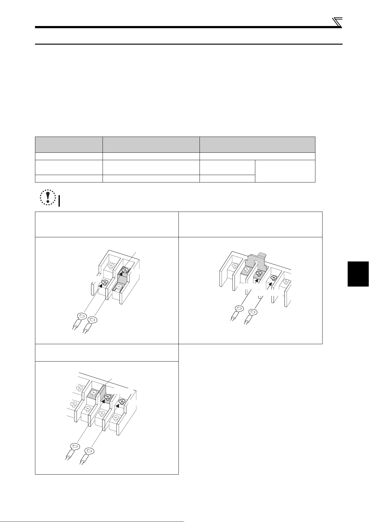
Connection of stand-alone option unit
2.4 Connection of stand-alone option unit
The inverter accepts a variety of stand-alone option units as required.
Incorrect connection will cause inverter damage or accident. Connect and operate the option unit carefully in accordance with
the corresponding option unit manual.
2.4.1 Connection of a dedicated external brake resistor (MRS type, MYS type, FR-ABR)
(FR-D720-025 or more, FR-D740-012 or more, FR-D720S-025 or more)
Install a dedicated brake resistor (MRS type, MYS type, FR-ABR) outside when the motor driven by the inverter is made to run
by the load, quick deceleration is required, etc. Connect a dedicated brake resistor (MRS type, MYS type, FR-ABR) to
terminal P/+ and PR. (For the locations of terminal P/+ and PR, refer to the terminal block layout (page 15).)
Set parameters below.
Connected Brake
Resistor
MRS type, MYS type 0 (initial value) —
MYS type (used at 100%
torque/6%ED)
FR-ABR 1 10%
Pr. 30 Regenerative function selection
Setting
16%
Pr. 70 Special regenerative brake duty Setting
NOTE
The brake resistor connected should only be the dedicated brake resistor.
FR-D720-070 to 165
FR-D740-012 to 080
FR-D720S-070, 100
Connect the brake resistor across terminals P/+ and PR.
Jumper
*1
Terminal P/+
Terminal PR
Connect the brake resistor across terminals P/+ and PR.
FR-D720-238, 318
FR-D740-120, 160
Terminal P/+
Brake resistor
Refer to page 110
Jumper
*1, *2
Terminal PR
2
WIRING
Brake resistor
FR-D720-025, 042
FR-D720S-025, 042
Connect the brake resistor across terminals P/+ and PR.
Jumper
*1
Terminal P/+
Terminal PR
Brake resistor
∗1 Do not remove a jumper across terminal P/+ and P1 except when connecting a DC reactor.
∗2 The shape of jumper differs according to capacities.
31
Page 43

Connection of stand-alone option unit
r
(1) When using the brake resistor (MRS type, MYS type) and high-duty brake resistor (FR-ABR)
It is recommended to configure a sequence, which shuts off power in the input side of the inverter by the external thermal
relay as shown below, to prevent overheat and burnout of the brake resistor (MRS type, MYS type) and high duty brake
resistor (FR-ABR) in case the regenerative brake transistor is damaged. (The brake resistor can not be connected to the
FR-D720-008 or 014 and FR-D720S-008 or 014.)
<Example 1>
Power supply
Inverter
Thermal relay
(OCR) (*1)
P/+
PR
MC
R/L1
S/L2
T/L3
*2
T
F
MC
OFF
ON
MC
OCR
Contact
High-duty brake
resistor (FR-ABR)
R
Power supply
<Example 2>
T
F
OFF
ON
MC
MC
R/L1
S/L2
MC
OCR
Contact
T/L3
B
C
*2
Inverter
P/+
PR
Thermal relay
(OCR) (*1)
∗1 Refer to the table below for the type number of each capacity of thermal relay and the diagram below for the connection.
∗2 When the power supply is 400V class, install a step-down transformer.
Power
Supply
Vol tag e
Brake Resistor
Thermal Relay Type
(Mitsubishi product)
Contact Rating
MRS120W200 TH-N20CXHZ-0.7A
110VAC 5A,
220VAC 2A(AC11 class)
110VDC 0.5A,
220VDC 0.25A(DC11class)
Contact Rating
200V
Power
Supply
Vol tag e
MRS120W100 TH-N20CXHZ-1.3A
MRS120W60 TH-N20CXHZ-2.1A
MRS120W40 TH-N20CXHZ-3.6A
MYS220W50
(two units in parallel)
High-duty
Brake Resistor
TH-N20CXHZ-5A
Thermal Relay Type
(Mitsubishi product)
FR-ABR-0.4K TH-N20CXHZ-0.7A
1/L1 5/L3
2/T1 6/T3
To the inverter
P/+ terminal
200V
400V
FR-ABR-0.75K TH-N20CXHZ-1.3A
FR-ABR-2.2K TH-N20CXHZ-2.1A
FR-ABR-3.7K TH-N20CXHZ-3.6A
FR-ABR-5.5K TH-N20CXHZ-5A
FR-ABR-7.5K TH-N20CXHZ-6.6A
FR-ABR-H0.4K TH-N20CXHZ-0.24A
FR-ABR-H0.75K TH-N20CXHZ-0.35A
FR-ABR-H1.5K TH-N20CXHZ-0.9A
FR-ABR-H2.2K TH-N20CXHZ-1.3A
110VAC 5A,
220VAC 2A(AC11 class)
110VDC 0.5A,
220VDC 0.25A(DC11 class)
FR-ABR-H3.7K TH-N20CXHZ-2.1A
FR-ABR-H5.5K TH-N20CXHZ-2.5A
FR-ABR-H7.5K TH-N20CXHZ-3.6A
High-duty brake
resistor (FR-ABR)
R
TH-N20
To a resisto
32
NOTE
Brake resistor can not be used with the brake unit, high power factor converter, power supply regeneration converter,
etc.
Do not use the brake resistor with a lead wire extended.
Do not connect a resistor directly to the DC terminals P/+ and N/-. This could cause a fire.
Page 44

Connection of stand-alone option unit
2.4.2 Connection of the brake unit (FR-BU2)
Connect the brake unit (FR-BU2(-H)) as shown below to improve the braking capability at deceleration. If the transistors in the
brake unit should become faulty, the resistor can be unusually hot. To prevent unusual overheat and fire, install a magnetic
contactor on the inverter's input side to configure a circuit so that a current is shut off in case of fault.
(1) Connection example with the GRZG type discharging resistor
OFFON
∗2
T
RR
MC
∗5
∗4
Three-phase AC
power supply
MCCB
MC
R/L1
S/L2
T/L3
MC
GRZG type
discharging resistor
U
V
W
Motor
IM
Inverter
P/+
∗1
N/-
(16.4feet or less)
∗1 Connect the inverter terminals (P/+ and N/-) and brake unit (FR-BU2) terminals so that their terminal names match
with each other.
(Incorrect connection will damage the inverter and brake unit.)
∗2 When the power supply is 400V class, install a step-down transformer.
∗3 The wiring distance between the inverter, brake unit (FR-BU2) and discharging resistor should be within 5m(16.4feet)
each. Even when the wiring is twisted, the cable length must not exceed 10m(32.8feet).
∗4 It is recommended to install an external thermal relay to prevent overheat of discharging resistor.
∗5 Refer to FR-BU2 manual for connection method of discharging resistor.
∗3
∗3
∗3
5m or less
FR-BU2
PR
P/+
∗1
N/-
BUE
SD
A
B
C
<Recommended external thermal relay>
Brake Unit Discharging Resistor
FR-BU2-1.5K GZG 300W-50Ω (one) TH-N20CXHZ 1.3A
FR-BU2-3.7K GRZG 200-10Ω (three in series) TH-N20CXHZ 3.6A
FR-BU2-7.5K GRZG 300-5Ω (four in series) TH-N20CXHZ 6.6A
FR-BU2-15K GRZG 400-2Ω (six in series) TH-N20CXHZ 1.1A
FR-BU2-H7.5K GRZG 200-10Ω (six in series) TH-N20CXHZ 3.6A
FR-BU2-H15K GRZG 300-5Ω (eight in series) TH-N20CXHZ 6.6A
Recommended External
Thermal Relay
2
WIRING
NOTE
Set "1" in Pr. 0 Brake mode selection of the FR-BU2 to use GRZG type discharging resistor.
Do not remove a jumper across terminal P/+ and P1 except when connecting a DC reactor.
33
Page 45
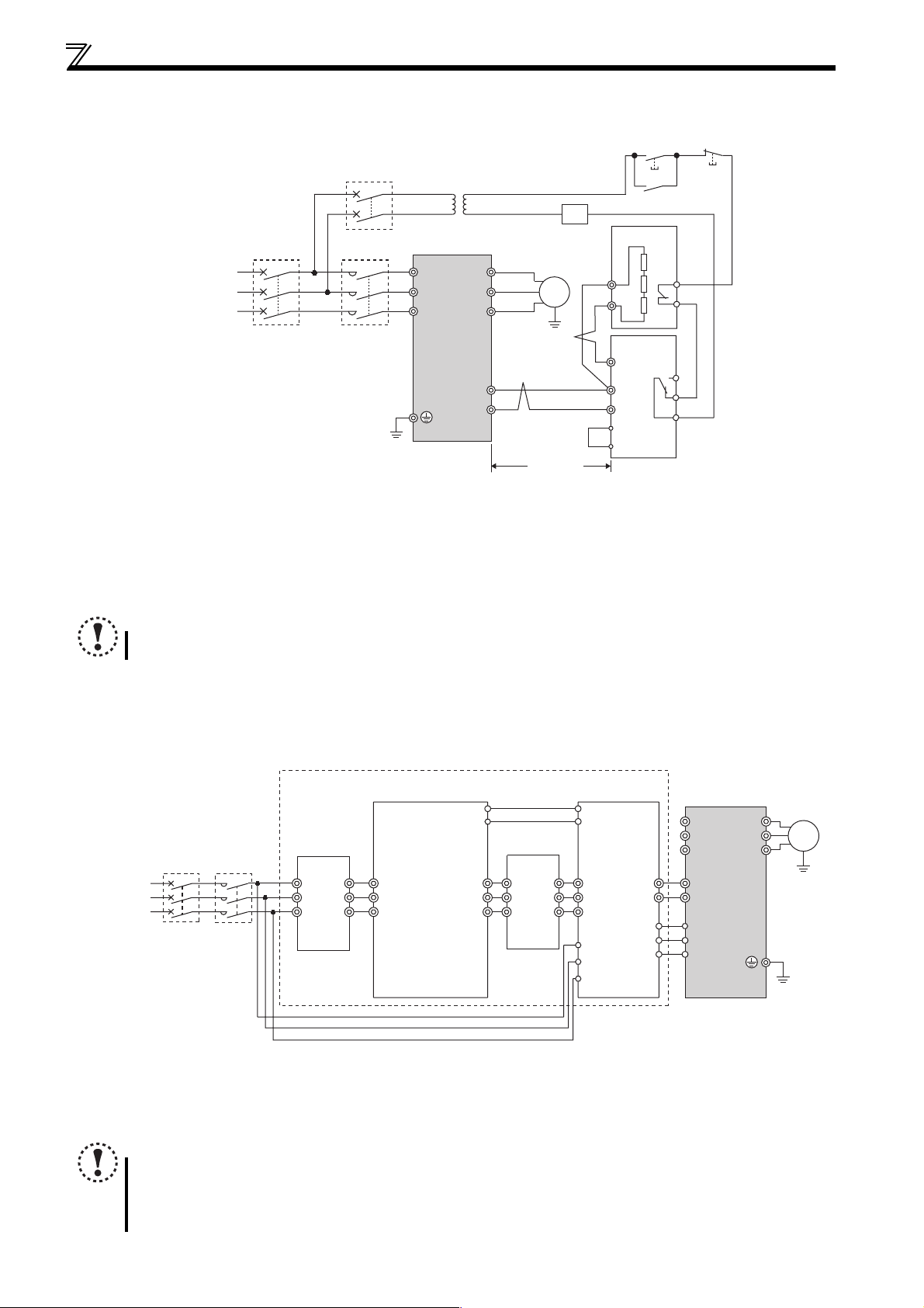
Connection of stand-alone option unit
r
(2) Connection example with the FR-BR(-H) type resistor
∗2
T
MCCB MC
Inverter
∗1
U
V
W
P/+
N/-
Three-phase AC
power supply
∗1 Connect the inverter terminals (P/+ and N/-) and brake unit (FR-BU2) terminals so that their terminal names match
with each other.
(Incorrect connection will damage the inverter and brake unit.)
∗2 When the power supply is 400V class, install a step-down transformer.
∗3 The wiring distance between the inverter, brake unit (FR-BU2) and resistor unit (FR-BR) should be within
5m(16.4feet) each. Even when the wiring is twisted, the cable length must not exceed 10m(32.8feet).
∗4 Normal: across TH1-TH2...close, Alarm: across TH1-TH2...open
∗5 A jumper is connected across BUE and SD in the initial status.
R/L1
S/L2
T/L3
MC
Motor
IM
∗3
∗3
5m or less
(16.4feet or less)
FR-BR
P
PR
FR-BU2
PR
P/+
∗1
N/-
BUE
SD
OFFON
MC
∗4
TH1
TH2
A
B
C
∗5
NOTE
Do not remove a jumper across terminal P/+ and P1 except when connecting a DC reactor.
2.4.3 Connection of the high power factor converter (FR-HC)
When connecting the high power factor converter (FR-HC) to suppress power harmonics, perform wiring securely as shown
below. Incorrect connection will damage the high power factor converter and inverter.
Outside box
(FR-HCB)
MC1
Reactor 1
MCCB
Three-phase
AC power
supply
∗1 Always keep the power input terminals R/L1, S/L2, T/L3 open. Incorrect connection will damage the inverter.
∗2 Do not insert an MCCB between the terminals P/+ and N/- (between P and P/+, between N and N/-). Opposite polarity of terminals N/- and P/+ will
damage the inverter.
∗3 Use Pr. 178 to Pr. 182 (input terminal function selection) to assign the terminals used for the X10, RES signal. (Refer to page 113)
∗4 Be sure to connect terminal RDY of the FR-HC to the X10 signal or MRS signal assigned terminal of the inverter, and connect terminal SE of the
FR-HC to terminal SD of the inverter. Without proper connecting, FR-HC will be damaged.
MC
(FR-HCL01)
R2
R
S2
S
T
T2
R2
S2
T2
MC2
R3
S3
T3
NOTE
The voltage phases of terminals R/L1, S/L2, T/L3 and terminals R4, S4, T4 must be matched.
Use sink logic (factory setting) when the FR-HC is connected. The FR-HC cannot be connected when source logic is
selected.
Do not remove a jumper across terminal P/+ and P1.
High power factor converter
Reactor 2
(FR-HCL02)
R3
R4
S4
S3
T4
T3
(FR-HC)
MC1
MC2
R4
S4
T4
R
Phase
S
detection
T
RDY
RSO
SE
Inverter
R/L1
∗1
S/L2
T/L3
P
N
P/+
∗2
N/-
∗4
X10
RES
SD
∗3
∗3
Moto
U
IM
V
W
34
Page 46
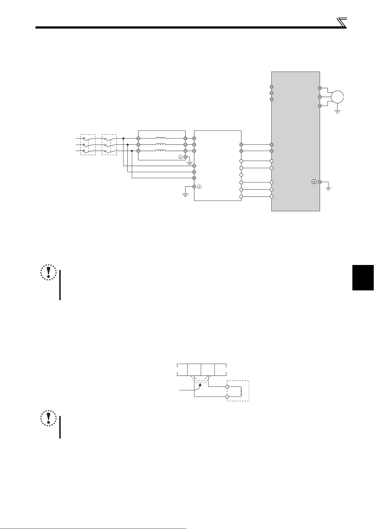
Connection of stand-alone option unit
A
2.4.4 Connection of the power regeneration common converter (FR-CV)
When connecting the power regeneration common converter (FR-CV), connect the inverter terminals (P/+ and N/-) and power
regeneration common converter (FR-CV) terminals as shown below so that their symbols match with each other.
R/L1
*1
S/L2
T/L3
Dedicated stand-alone
1
MCCB
Three-phase
C power supply
∗1 Always keep the power input terminals R/L1, S/L2, T/L3 open. Incorrect connection will damage the inverter.
∗2 Do not insert an MCCB between the terminals P/+ and N/- (between P/L+ and P/+, between N/L- and N/-). Opposite polarity of terminals
N/- and P/+ will damage the inverter.
∗3 Always connect the power supply and terminals R/L11, S/L21, T/MC1.
Operating the inverter without connecting them will damage the power regeneration common converter.
∗4 Use Pr. 178 to Pr. 182 (input terminal function selection) to assign the terminals used for the X10, RES signal. (Refer to page 113)
∗5 Be sure to connect terminal RDYB of the FR-CV to the X10 signal or MRS signal assigned terminal of the inverter, and connect terminal
SE of the FR-CV to terminal SD of the inverter. Without proper connecting, FR-CV will be damaged.
MC
reactor (FR-CVL)
R/L11
S/L
T/L31
21
R2/L12
S2/L22
T2/L32
FR-CV type power
regeneration common converter
R2/L1
S2/L2
T2/L3
R/L11
S/L21
T/MC1
P/L+
N/L-
P24
*3
SD
RDYA
RDYB
*5
RSO
SE
P/+
N/-
PC
SD
X10
RES
SD
Inverter
*2
*4
*4
NOTE
The voltage phases of terminals R/L11, S/L21, T/MC1 and terminals R2/L1, S2/L2, T2/L3 must be matched.
Use sink logic (factory setting) when the FR-CV is connected. The FR-CV cannot be connected when source logic is
selected.
Do not remove a jumper across terminal P/+ and P1.
U
V
IM
W
2
2.4.5 Connection of a DC reactor (FR-HEL)
WIRING
When using the DC reactor (FR-HEL), connect it across terminals P/+ and P1.
In this case, the jumper connected across terminals P/+ and P1 must be removed. Otherwise, the reactor will not exhibit its
performance.
P/+
P1
FR-HEL
Remove the jumper.
NOTE
The wiring distance should be within 5m (16.4feet).
The size of the cables used should be equal to or larger than that of the power supply cables (R/L1, S/L2, T/L3). (Refer
to page 17)
35
Page 47

MEMO
36
Page 48

3
PRECAUTIONS FOR USE
OF THE INVERTER
This chapter explains the "PRECAUTIONS FOR USE OF THE
INVERTER" for use of this product.
Always read the instructions before using the equipment
3.1 EMC and leakage currents .......................................................... 38
3.2 Installation of power factor improving reactor ......................... 43
3.3 Power-off and magnetic contactor (MC) .................................... 44
3.4 Inverter-driven 400V class motor ................................................ 45
3.5 Precautions for use of the inverter ............................................ 46
1
2
3.6 Failsafe of the system which uses the inverter ........................ 48
3
4
5
6
37
7
Page 49

EMC and leakage currents
3.1 EMC and leakage currents
3.1.1 Leakage currents and countermeasures
Capacitances exist between the inverter I/O cables, other cables and earth and in the motor, through which a leakage current
flows. Since its value depends on the static capacitances, carrier frequency, etc., low acoustic noise operation at the
increased carrier frequency of the inverter will increase the leakage current. Therefore, take the following measures. Select
the earth leakage current breaker according to its rated sensitivity current, independently of the carrier frequency setting.
(1) To-earth (ground) leakage currents
Leakage currents may flow not only into the inverter's own line but also into the other lines through the earth (ground) cable,
etc. These leakage currents may operate earth (ground) leakage circuit breakers and earth leakage relays unnecessarily.
Suppression technique
If the carrier frequency setting is high, decrease the Pr. 72 PWM frequency selection setting.
Note that motor noise increases. Selecting Pr. 240 Soft-PWM operation selection makes the sound inoffensive.
By using earth leakage circuit breakers designed for harmonic and surge suppression in the inverter's own line and other
line, operation can be performed with the carrier frequency kept high (with low noise).
To-earth (ground) leakage currents
Take caution as long wiring will increase the leakage current. Decreasing the carrier frequency of the inverter reduces the
leakage current.
Increasig the motor capacity increases the leakage current. The leakage current of the 400V class is larger than that of
the 200V class.
(2) Line-to-line leakage currents
Harmonics of leakage currents flowing in static capacitances between the inverter output cables may operate the external
thermal relay unnecessarily. When the wiring length is long (50m (164.04feet) or more) for the 400V class small-capacity model
(FR-D740-160 or less), the external thermal relay is likely to operate unnecessarily because the ratio of the leakage current to
the rated motor current increases.
Line-to-line leakage current data example
Motor Capacity
(kW (HP))
0.4 (1/2) 1.1 620 1000
0.75 (1) 1.9 680 1060
1.5 (2) 3.5 740 1120
2.2 (3) 4.1 800 1180
3.7 (5) 6.4 880 1260
5.5 (7.5) 9.7 980 1360
Rated Motor
Current (A)
Wiring length 50m
Leakage Current (mA) *
Wiring length 100m
(164.04feet)
*The leakage currents of the 200V class are about a half.
(328.08feet)
Motor: SF-JR 4P
Carrier frequency: 14.5kHz
Used wire: 2mm
Cabtyre cable
2
, 4 cores
Power
supply
MCCB MC
Inverter
Thermal relay
Motor
IM
Line-to-line static
capacitances
Line-to-line leakage currents path
Measures
Use Pr. 9 Electronic thermal O/L relay.
If the carrier frequency setting is high, decrease the Pr. 72 PWM frequency selection setting.
Note that motor noise increases. Selecting Pr. 240 Soft-PWM operation selection makes the sound inoffensive.
To ensure that the motor is protected against line-to-line leakage currents, it is recommended to use a temperature
sensor to directly detect motor temperature.
Installation and selection of moulded case circuit breaker
Install a moulded case circuit breaker (MCCB) on the power receiving side to protect the wiring of the inverter input side.
Select the MCCB according to the inverter input side power factor (which depends on the power supply voltage, output
frequency and load). Especially for a completely electromagnetic MCCB, one of a slightly large capacity must be selected
since its operation characteristic varies with harmonic currents. (Check it in the data of the corresponding breaker.) As an
earth leakage current breaker, use the Mitsubishi earth leakage current breaker designed for harmonics and surge
suppression.
38
Page 50

EMC and leakage currents
-
W
(3) Selection of rated sensitivity current of earth (ground) leakage current breaker
When using the earth leakage current breaker with the inverter circuit, select its rated sensitivity current as follows,
independently of the PWM carrier frequency.
Breaker designed for harmonic and
surge suppression
Rated sensitivity current:
I∆n≥10×(Ig1+Ign+Igi+Ig2+Igm)
Standard breaker
Rated sensitivity current:
I∆n≥10×{Ig1+Ign+Igi+3×(Ig2+Igm)}
Example of leakage current of
cable path per 1km during the
commercial power supply operation
when the CV cable is routed in
metal conduit
(200V 60Hz)
120
100
80
60
40
20
Leakage currents (mA)
0
2 3.5
8142230386080
5.5
Cable size (mm2)
100
150
Example of leakage current
of three-phase induction motor
during the commercial
power supply operation
(200V 60Hz)
1.0
0.7
0.5
0.3
0.2
0.1
0.07
0.05
0.03
Leakage currents (mA)
0.02
0.1 0.2
<Example>
5.5mm
ELB
Ig1 Ign
Noise
filter
2 ×
5m 5.5mm
Inverter
Igi
2 ×
60m
IM
Ig2 Igm
3φ
400V
2.2k
Ig1, Ig2: Leakage currents in wire path during commercial
power supply operation
Ign: Leakage current of inverter input side noise filter
Igm: Leakage current of motor during commercial power
supply operation
Igi: Leakage current of inverter unit
0.75
2.2
0.4
Motor capacity (kW)
5.5 11
1.5
3.7
Example of leakage current per 1km during
the commercial power supply operation
when the CV cable is routed in metal conduit
(Three-phase three-wire delta
connection 400V60Hz)
120
100
80
60
40
20
leakage currents (mA)
0
2 3.5
20
15
7.5
For " " connection, the amount of leakage current is appox.1/3 of the above value.
Cable
8142230386080
5.5
size (mm2)
100
150
Example of leakage current of three
phase induction motor during the
commercial power supply operation
(Totally-enclosed fan-cooled
type motor 400V60Hz)
2. 0
1. 0
0. 7
0. 5
0. 3
0. 2
leakage currents (mA)
0. 1
1.5 3.7
Motor capacity (kW)
7.5 15
2.2
Selection example (in the case of the left figure (400V class connection))
Breaker Designed for
Harmonic and Surge
Standard Breaker
Suppression
Leakage current Ig1 (mA)
1
×
66 ×
3
5m
1000m
Leakage current Ign (mA) 0 (without noise filter)
Leakage current Igi (mA) 1
Leakage current Ig2 (mA)
1
×
66 ×
3
60m
1000m
Motor leakage current Igm (mA) 0.36
Total leakage current (mA) 2.79 6.15
Rated sensitivity current (mA) (≥ Ig × 10) 30 100
11 205.5
= 0.11
= 1.32
3
NOTE
Install the earth leakage breaker (ELB) on the input side of the inverter.
In the connection earthed-neutral system, the sensitivity current is blunt against an earth (ground) fault in the
inverter output side. Earthing (Grounding) must conform to the requirements of national and local safety regulations
and electrical codes. (NEC section 250, IEC 536 class 1 and other applicable standards)
When the breaker is installed on the output side of the inverter, it may be unnecessarily operated by harmonics even
if the effective value is less than the rating.
In this case, do not install the breaker since the eddy current and hysteresis loss will increase, leading to temperature
rise.
General products indicate the following models. ...... BV-C1, BC-V, NVB, NV-L, NV-G2N, NV-G3NA, NV-2F earth leakage
relay (except NV-ZHA), NV with AA neutral wire open-phase protection
The other models are designed for harmonic and surge suppression ....NV-C/NV-S/MN series, NV30-FA, NV50-FA, BV-
C2, earth leakage alarm breaker (NF-Z), NV-ZHA, NV-H
39
PRECAUTIONS FOR USE OF THE INVERTER
Page 51
EMC and leakage currents
)
3.1.2 EMC measures
Some electromagnetic noises enter the inverter to malfunction it and others are radiated by the inverter to malfunction
peripheral devices. Though the inverter is designed to have high immunity performance, it handles low-level signals, so it
requires the following basic techniques. Also, since the inverter chops outputs at high carrier frequency, that could generate
electromagnetic noises. If these electromagnetic noises cause peripheral devices to malfunction, EMI measures should be
taken to suppress noises. These techniques differ slightly depending on EMI paths.
(1) Basic techniques
Do not run the power cables (I/O cables) and signal cables of the inverter in parallel with each other and do not bundle
them.
Use twisted shield cables for the detector connecting and control signal cables and connect the sheathes of the shield
cables to terminal SD.
Earth (Ground) the inverter, motor, etc. at one point.
(2) Techniques to reduce electromagnetic noises that enter and malfunction the inverter (Immunity measures)
When devices that generate many electromagnetic noises (which use magnetic contactors, magnetic brakes, many relays,
for example) are installed near the inverter and the inverter may be malfunctioned by electromagnetic noises, the following
measures must be taken:
Provide surge suppressors for devices that generate many electromagnetic noises to suppress electromagnetic noises.
Fit data line filters (page 41) to signal cables.
Earth (Ground) the shields of the detector connection and control signal cables with cable clamp metal.
(3) Techniques to reduce electromagnetic noises that are radiated by the inverter to malfunction peripheral devices (EMI
measures)
Inverter-generated electromagnetic noises are largely classified into those radiated by the cables connected to the inverter
and inverter main circuits (I/O), those electromagnetically and electrostatically induced to the signal cables of the peripheral
devices close to the main circuit power supply, and those transmitted through the power supply cables.
Inverter
generated
electromagnetic
noise
Air propagated
electromagnetic
noise
Electromagnetic
induction noise
Electrostatic
induction noise
Electrical path
propagated noise
Noise directly
radiated from inverter
Noise radiated from
power supply cable
Noise radiated from
motor connection cable
Path 4), 5)
Path 6)
Noise propagated through
power supply cable
Noise from earth (ground)
cable due to leakage
current
Path 1
Path 2)
Path 3)
Path 7)
Path 8)
(7)
Instrument Receiver
(2)
(1)
(3)
Motor
(5)
Inverter
IM
(7)
(4)
(6)
(3)
Telephone
Sensor
power supply
(1)
(8)
Sensor
40
Page 52

Propagation Path Measures
When devices that handle low-level signals and are liable to malfunction due to electromagnetic noises, e.g.
instruments, receivers and sensors, are contained in the enclosure that contains the inverter or when their signal
cables are run near the inverter, the devices may be malfunctioned by air-propagated electromagnetic noises. The
following measures must be taken:
(1)(2)(3)
(4)(5)(6)
(7)
(8)
Install easily affected devices as far away as possible from the inverter.
Run easily affected signal cables as far away as possible from the inverter and its I/O cables.
Do not run the signal cables and power cables (inverter I/O cables) in parallel with each other and do not bundle them.
Insert common mode filters into I/O and capacitors between the input lines to suppress cable-radiated noises.
Use shield cables as signal cables and power cables and run them in individual metal conduits to produce further effects.
When the signal cables are run in parallel with or bundled with the power cables, magnetic and static induction noises
may be propagated to the signal cables to malfunction the devices and the following measures must be taken:
Install easily affected devices as far away as possible from the inverter.
Run easily affected signal cables as far away as possible from the I/O cables of the inverter.
Do not run the signal cables and power cables (inverter I/O cables) in parallel with each other and do not bundle them.
Use shield cables as signal cables and power cables and run them in individual metal conduits to produce further effects.
When the power supplies of the peripheral devices are connected to the power supply of the inverter in the same line,
inverter-generated noises may flow back through the power supply cables to malfunction the devices and the
following measures must be taken:
Install the common mode filter (FR-BLF, FR-BSF01) to the power cables (output cable) of the inverter.
When a closed loop circuit is formed by connecting the peripheral device wiring to the inverter, leakage currents may
flow through the earth (ground) cable of the inverter to malfunction the device. In such a case, disconnection of the
earth (ground) cable of the device may cause the device to operate properly.
EMC and leakage currents
Data line filter
As immunity measures it may effective, provide a data line filter for the detector cable etc.
EMC measures
Install common mode filter
on inverter input side.
Install capacitor type FR-BIF filter
on inverter input side.
Separate inverter and power line by
more than 30cm (11.81inches) (at least
10cm (3.93inches) from sensor circuit.
FR- BLF
FR- BSF01
Inverter
power
supply
Control
power
supply
Do not earth (ground)
enclosure directly.
Do not earth (ground) control cable.
Enclosure
FRBSF01
for sensor
Decrease
carrier frequency
Inverter
FRBIF
Power
supply
Install common mode filter
on inverter output side.
FRBSF01
Use 4-core cable for motor
power cable and use one
cable as earth (ground) cable.
Use a twisted pair shielded cable
Sensor
Do not earth (ground) shield but
connect it to signal common cable.
NOTE
For compliance with the EU EMC directive, refer to the Installation Guideline.
IM
FR- BLF
FR- BSF01
Motor
3
41
PRECAUTIONS FOR USE OF THE INVERTER
Page 53

EMC and leakage currents
3.1.3 Power supply harmonics
The inverter may generate power supply harmonics from its converter circuit to affect the power generator, power capacitor
etc. Power supply harmonics are different from noise and leakage currents in source, frequency band and transmission path.
Take the following countermeasure suppression techniques.
The differences between harmonics and RF noises are indicated below:
Item Harmonics Noise
Frequency
Environment To-electric channel, power impedance To-space, distance, wiring path
Quantitative understanding Theoretical calculation possible Random occurrence, quantitative grasping difficult
Generated amount Nearly proportional to load capacity
Affected equipment immunity Specified in standard per equipment Different depending on maker's equipment specifications
Suppression example Provide reactor. Increase distance.
Suppression technique
The harmonic current generated from the inverter
to the input side differs according to various
conditions such as the wiring impedance, whether
a reactor is used or not, and output frequency and
output current on the load side.
For the output frequency and output current, we
understand that they should be calculated in the
conditions under the rated load at the maximum
operating frequency.
Normally 40th to 50th degrees or less
(up to 3kHz or less)
Power
supply
High frequency (several 10kHz to 1GHz order)
Change with current variation ratio (larger as switching
speed increases)
DC reactor
(FR-HEL)
MCCB MC
R
S
TZ
AC reactor
(FR-HAL)
X
Y
P/+
R/L1
S/L2
T/L3
Inverter
P1
U
V
W
Do not insert
power factor improving
capacitor.
IM
NOTE
The power factor improving capacitor and surge suppressor on the inverter output side may be overheated or damaged
by the harmonic components of the inverter output. Also, since an excessive current flows in the inverter to activate
overcurrent protection, do not provide a capacitor and surge suppressor on the inverter output side when the motor is
driven by the inverter. For power factor improvement, install a reactor on the inverter input side or in the DC circuit.
42
Page 54
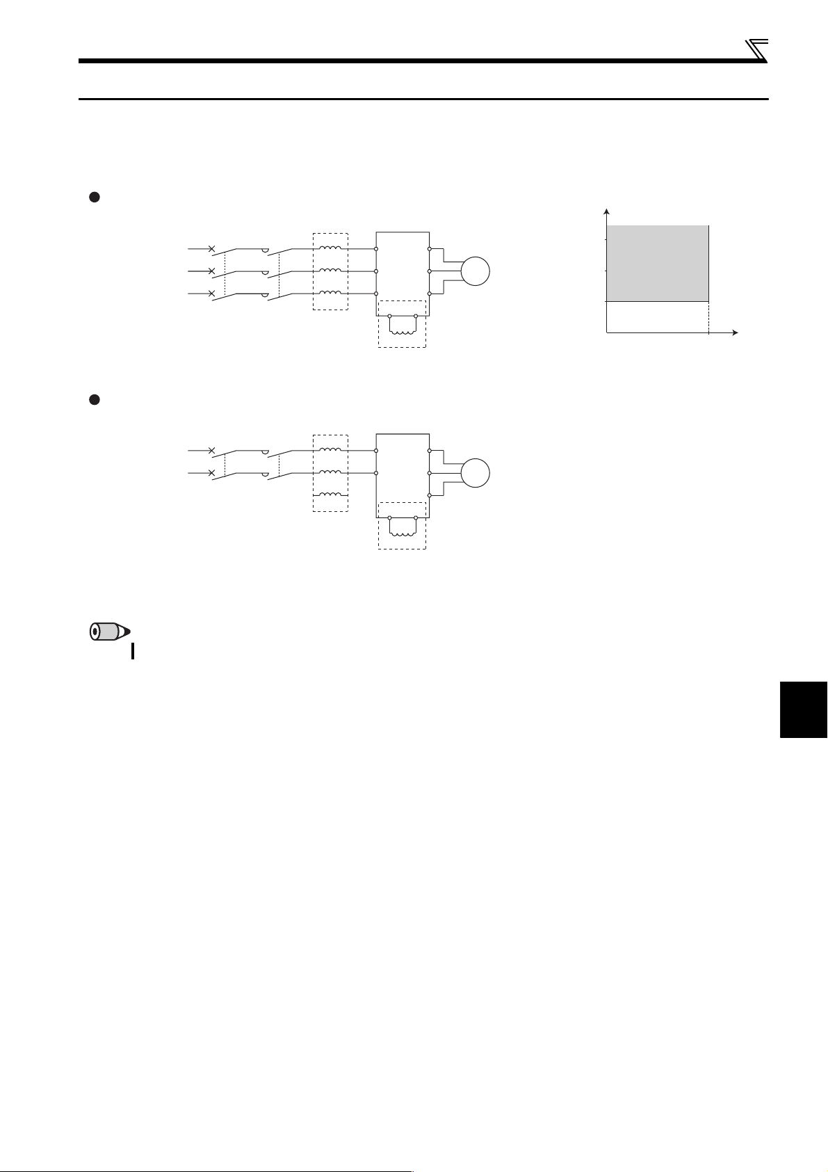
Installation of power factor improving reactor
3.2 Installation of power factor improving reactor
When the inverter is connected near a large-capacity power transformer (500kVA or more) or when a power capacitor is to be
switched over, an excessive peak current may flow in the power input circuit, damaging the converter circuit. To prevent this,
always install an optional reactor (FR-HAL, FR-HEL).
Three-phase power input
Power supply
MCCB MC
AC reactor
(FR-HAL)
R
S
TZ
X
Y
Inverter
U
R/L1
V
S/L2
W
T/L3
P1
P/+
DC reactor
(FR-HEL) *
IM
Single-phase power input
AC reactor
MCCB MC
Power supply
∗ When connecting the FR-HEL, remove the jumper across terminals P/+ and P1.
The wiring length between the FR-HEL and inverter should be 5m (16.4feet) maximum and minimized.
(FR-HAL)
R
S
TZ
X
Y
Inverter
R/L1
U
S/L2
V
W
P/+
P1
DC reactor
(FR-HEL) *
IM
1500
Range requiring
500
0
installation of
the reactor
Wiring length
1000
(kVA)
Power supply system capacity
(m)
10
(32.8feet)
REMARKS
Use the same wire size as that of the power supply wire (R/L1, S/L2, T/L3). (Refer to page 17)
3
43
PRECAUTIONS FOR USE OF THE INVERTER
Page 55

Power-off and magnetic contactor (MC)
r
3.3 Power-off and magnetic contactor (MC)
(1) Inverter input side magnetic contactor (MC)
On the inverter input side, it is recommended to provide an MC for the following purposes.
(Refer to page 4 for selection.)
1) To release the inverter from the power supply when the fault occurs or when the drive is not functioning (e.g. emergency
stop operation). When cycle operation or heavy-duty operation is performed with an optional brake resistor connected,
overheat and burnout of the discharging resistor can be prevented if a regenerative brake transistor is damaged due to
insufficient heat capacity of the discharging resistor and excess regenerative brake duty.
2) To prevent any accident due to an automatic restart at restoration of power after an inverter stop made by a power failure
3) The control power supply for inverter is always running and consumes a little power. When stopping the inverter for an
extended period of time, powering off the inverter will save power slightly.
4) To separate the inverter from the power supply to ensure safe maintenance and inspection work.
The inverter's input side MC is used for the above purpose, select class JEM1038-AC3 MC for the inverter input side
current when making an emergency stop during normal operation.
REMARKS
Since repeated inrush currents at power on will shorten the life of the converter circuit (switching life is about 1,000,000 times.),
frequent starts and stops of the MC must be avoided. Turn on/off the inverter start controlling terminals (STF, STR) to run/stop the
inverter.
Inverter start/stop circuit example
As shown on the left, always use the start signal
(ON or OFF across terminals STF or STR-SD) to
make a start or stop.
∗1 When the power supply is 400V class, install a step-down
transformer.
Three-phase AC
power supply
Operation preparation
OFF
Start/Stop
MC
Operation
Stop
ON
MC
RA
MCCB MC
T
MC
RA
Inverter
R/L1
S/L2
T/L3
*1
RA
STF(STR)
SD
U
V
W
C
B
A
Moto
(2) Handling of inverter output side magnetic contactor
Switch the magnetic contactor between the inverter and motor only when both the inverter and motor are at a stop. When the
magnetic contactor is turned on while the inverter is operating, overcurrent protection of the inverter and such will activate.
When an MC is provided for switching to the commercial power supply, for example, switch it on/off after the inverter and
motor have stopped.
44
Page 56

Inverter-driven 400V class motor
3.4 Inverter-driven 400V class motor
In the PWM type inverter, a surge voltage attributable to wiring constants is generated at the motor terminals. Especially for a
400V class motor, the surge voltage may deteriorate the insulation. When the 400V class motor is driven by the inverter,
consider the following measures:
Measures
It is recommended to take either of the following measures:
(1) Rectifying the motor insulation and limiting the PWM carrier frequency according to the wiring
length
For the 400V class motor, use an insulation-enhanced motor.
Specifically,
1) Specify the "400V class inverter-driven insulation-enhanced motor".
2) For the dedicated motor such as the constant-torque motor and low-vibration motor, use the "inverter-driven, dedicated
motor".
3) Set Pr. 72 PWM frequency selection as indicated below according to the wiring length
Wiring Length
50m (164.04feet) or less
Pr. 72 PWM frequency selection 15 (14.5kHz) or less 8 (8kHz) or less 2 (2kHz) or less
50m to 100m
(164.04feet to 328.09feet)
exceeding 100m
(328.09feet)
(2) Suppressing the surge voltage on the inverter side
Connect the surge voltage suppression filter (FR-ASF-H/FR-BMF-H) on the inverter output side.
NOTE
For details of Pr. 72 PWM frequency selection, refer to page 148.
For explanation of surge voltage suppression filter (FR-ASF-H/FR-BMF-H), refer to the manual of each option
3
45
PRECAUTIONS FOR USE OF THE INVERTER
Page 57

Precautions for use of the inverter
3.5 Precautions for use of the inverter
The FR-D700 series is a highly reliable product, but incorrect peripheral circuit making or operation/handling method may
shorten the product life or damage the product.
Before starting operation, always recheck the following items.
(1) Use crimping terminals with insulation sleeve to wire the power supply and motor.
(2) Application of power to the output terminals (U, V, W) of the inverter will damage the inverter. Never perform such wiring.
(3) After wiring, wire offcuts must not be left in the inverter.
Wire offcuts can cause an alarm, failure or malfunction. Always keep the inverter clean.
When drilling mounting holes in an enclosure etc., take care not to allow chips and other foreign matter to enter the
inverter.
(4) Use cables of the size to make a voltage drop 2% maximum.
If the wiring distance is long between the inverter and motor, a main circuit cable voltage drop will cause the motor torque
to decrease especially at the output of a low frequency.
Refer to page 17 for the recommended wire sizes.
(5) The overall wiring length should be 500m (1640.42feet) maximum.
Especially for long distance wiring, the fast-response current limit function may decrease or the equipment connected to
the secondary side may malfunction or become faulty under the influence of a charging current due to the stray capacity
of the wiring. Therefore, note the overall wiring length. (Refer to page 19)
(6) Electromagnetic wave interference
The input/output (main circuit) of the inverter includes high frequency components, which may interfere with the
communication devices (such as AM radios) used near the inverter. In this case, install the FR-BIF optional capacitor
type filter (for use in the input side only) or FR-BSF01 or FR-BLF common mode filter to minimize interference.
(7) Do not install a power factor correction capacitor, surge suppressor or capacitor type filter on the inverter output side.
This will cause the inverter to trip or the capacitor and surge suppressor to be damaged. If any of the above devices are
connected, immediately remove them. (When using capacitor type filter (FR-BIF) for single-phase power supply
specification, make sure of secure insulation of T/L3-phase, and connect to the input side of the inverter.)
(8) For some short time after the power is switched off, a high voltage remains in the smoothing capacitor. When accessing
the inverter for inspection, wait for at least 10 minutes after the power supply has been switched off, and then make sure
that the voltage across the main circuit terminals P/+ and N/- of the inverter is not more than 30VDC using a tester, etc.
The capacitor is charged with high voltage for some time after power off and it is dangerous.
(9) A short circuit or earth (ground) fault on the inverter output side may damage the inverter modules.
Fully check the insulation resistance of the circuit prior to inverter operation since repeated short circuits caused by
peripheral circuit inadequacy or an earth (ground) fault caused by wiring inadequacy or reduced motor insulation
resistance may damage the inverter modules.
Fully check the to-earth (ground) insulation and phase to phase insulation of the inverter output side before power-on.
Especially for an old motor or use in hostile atmosphere, securely check the motor insulation resistance etc.
(10) Do not use the inverter input side magnetic contactor to start/stop the inverter.
Always use the start signal (turn on/off STF and STR signals) to start/stop the inverter. (Refer to page 44)
(11) Across P/+ and PR terminals, connect only an external regenerative brake discharging resistor.
Do not connect a mechanical brake.
The brake resistor can not be connected to the FR-D720-008 and 014 and FR-D720S-008 and 014. Never short
between terminals P/+ and PR.
46
Page 58

Precautions for use of the inverter
(12) Do not apply a voltage higher than the permissible voltage to the inverter I/O signal circuits.
Application of a voltage higher than the permissible voltage to the inverter I/O signal circuits or opposite polarity may
damage the I/O devices. Especially check the wiring to prevent the speed setting potentiometer from being connected
incorrectly to short terminals 10-5.
(13) Provide electrical and mechanical interlocks for MC1 and MC2
which are used for bypass operation. When the wiring is
incorrect and if there is a bypass operation circuit as shown
right, the inverter will be damaged due to arcs generated at the
time of switch-over or chattering caused by a sequence error.
(14) If the machine must not be restarted when power is restored after a power failure, provide a magnetic contactor in the
inverter's input side and also make up a sequence which will not switch on the start signal.
If the start signal (start switch) remains on after a power failure, the inverter will automatically restart as soon as the
power is restored.
(15) Instructions for overload operation
When performing operation of frequent start/stop of the inverter, rise/fall in the temperature of the transistor element of
the inverter will repeat due to a repeated flow of large current, shortening the life from thermal fatigue. Since thermal
fatigue is related to the amount of current, the life can be increased by reducing current at locked condition, starting
current, etc. Decreasing current may increase the life. However, decreasing current will result in insufficient torque and
the inverter may not start. Therefore, choose the inverter which has enough allowance for current (up to 2 rank larger in
capacity).
(16) Make sure that the specifications and rating match the system requirements.
Power
supply
R/L1
S/L2
T/L3
Inverter
U
V
W
Undesirable current
MC1
MC2
Interlock
IM
(17) When the motor speed is unstable, due to change in the frequency setting signal caused by electromagnetic noises from
the inverter, take the following measures while applying the motor speed by the analog signal.
Do not run the signal cables and power cables (inverter I/O cables) in parallel with each other and do not bundle them.
Run signal cables as far away as possible from power cables (inverter I/O cables).
Use shield cables as signal cables.
Install a ferrite core on the signal cable (Example: ZCAT3035-1330 TDK).
3
47
PRECAUTIONS FOR USE OF THE INVERTER
Page 59

Failsafe of the system which uses the inverter
3.6 Failsafe of the system which uses the inverter
When a fault occurs, the inverter trips to output a fault signal. However, a fault output signal may not be output at an inverter
fault occurrence when the detection circuit or output circuit fails, etc. Although Mitsubishi assures best quality products,
provide an interlock which uses inverter status output signals to prevent accidents such as damage to machine when the
inverter fails for some reason and at the same time consider the system configuration where failsafe from outside the inverter,
without using the inverter, is enabled even if the inverter fails.
(1) Interlock method which uses the inverter status output signals
By combining the inverter status output signals to provide an interlock as shown below, an inverter alarm can be
detected.
No Interlock Method Check Method Used Signals Refer to Page
Inverter protective
1)
function operation
Inverter operating status Operation ready signal check
2)
Inverter running status
3)
Inverter running status
4)
Operation check of an alarm contact
Circuit error detection by negative logic
Logic check of the start signal and
running signal
Logic check of the start signal and
output current
Fault output signal
(ALM signal)
Operation ready signal
(RY signal)
Start signal
(STF signal, STR signal)
Running signal (RUN signal)
Start signal
(STF signal, STR signal)
Output current detection signal
(Y12 signal)
122
121
117, 121
117, 124
1) Check by the inverter fault output signal
When the fault occurs and the inverter trips, the fault output
signal (ALM signal) is output (ALM signal is assigned to
terminal ABC in the initial setting).
Check that the inverter functions properly.
In addition, negative logic can be set (on when the inverter is
normal, off when the fault occurs).
2) Checking the inverter operating status by the inverter
operation ready completion signal
Operation ready signal (RY signal) is output when the
inverter power is on and the inverter becomes operative.
Check if the RY signal is output after powering on the
inverter.
3) Checking the inverter operating status by the start signal
input to the inverter and inverter running signal.
The inverter running signal (RUN signal) is output when the
inverter is running (RUN signal is assigned to terminal RUN
in the initial setting).
Check if RUN signal is output when inputting the start signal
to the inverter (forward signal is STF signal and reverse
signal is STR signal). For logic check, note that RUN signal
is output for the period from the inverter decelerates until
output to the motor is stopped, configure a sequence
considering the inverter deceleration time.
ALM
(when output
at NC contact)
RES
Power
supply
STF
RH
Pr. 13 Starting frequency
Output frequency
RY
RUN
Inverter fault occurrence
(trip)
Output frequency
OFF
ON
OFF
ON
Reset processing
(about 1s)
Reset ON
ON OFF
ON OFF
ON
DC injection brake
operation point
DC injection
brake operation
Reset
processing
ON OFF
ON OFF
Time
Time
48
Page 60
Failsafe of the system which uses the inverter
4) Checking the motor operating status by the start signal input to the inverter and inverter output current detection signal.
The output current detection signal (Y12 signal) is output when the inverter operates and currents flows in the motor.
Check if Y12 signal is output when inputting the start signal to the inverter (forward signal is STF signal and reverse
signal is STR signal). Note that the current level at which Y12 signal is output is set to 150% of the inverter rated current
in the initial setting, it is necessary to adjust the level to around 20% using no load current of the motor as reference with
Pr.150 Output current detection level.
For logic check, as same as the inverter running signal (RUN signal), the inverter outputs for the period from the inverter
decelerates until output to the motor is stopped, configure a sequence considering the inverter deceleration time.
Output
Signal
ALM 99 199
RY 11 111
RUN 0 100
Y12 12 112
Pr. 190, Pr. 192 Setting
Positive logic Negative logic
When using various signals, assign functions to Pr.190, Pr.192
(output terminal function selection) referring to the table on the
left.
NOTE
Changing the terminal assignment using Pr. 190, Pr. 192 (output terminal function selection) may affect the other functions.
Make setting after confirming the function of each terminal.
(2) Backup method outside the inverter
Even if the interlock is provided by the inverter status signal, enough failsafe is not ensured depending on the failure
status of the inverter itself. For example, when the inverter CPU fails, even if the interlock is provided using the inverter
fault signal, start signal and RUN signal, there is a case where a fault signal is not output and RUN signal is kept output
even if an inverter fault occurs.
Provide a speed detector to detect the motor speed and current detector to detect the motor current and consider the
backup system such as checking up as below according to the level of importance of the system.
1) Start signal and actual operation check
Check the motor running and motor current while the start signal is input to the inverter by comparing the start signal to
the inverter and detected speed of the speed detector or detected current of the current detector. Note that the motor
current runs as the motor is running for the period until the motor stops since the inverter starts decelerating even if the
start signal turns off. For the logic check, configure a sequence considering the inverter deceleration time. In addition, it is
recommended to check the three-phase current when using the current detector.
2) Command speed and actual operation check
Check if there is no gap between the actual speed and commanded speed by comparing the inverter speed command
and detected speed of the speed detector.
Controller
System failure
Inverter
To the alarm detection sensor
Sensor
(speed, temperature,
air volume, etc.)
3
PRECAUTIONS FOR USE OF THE INVERTER
49
Page 61

MEMO
50
Page 62

4
V/F
GP
MFVC
PARAMETERS
This chapter explains the "PARAMETERS" for use of this
product.
Always read the instructions before using the equipment.
The abbreviations in the explanations below are as follows:
V/F
V/F
GP
GP
(Parameters without any indication are valid for both control)
......V/F control
MFVC
MFVC
......General-purpose magnetic-flux vector control
1
2
3
4
5
6
7
51
Page 63

Operation panel
4.1 Operation panel
4.1.1 Names and functions of the operation panel
The operation panel cannot be removed from the inverter.
Operation mode indication
PU: Lit to indicate PU operation mode.
EXT: Lit to indicate external operation
mode.
NET: Lit to indicate network operation
mode.
PU, EXT: Lit to indicate external/PU
combined operation mode 1, 2.
Unit indication
Hz: Lit to indicate frequency.
(Flickers when the set frequency
monitor is displayed.)
A: Lit to indicate current.
(Both "Hz" and "A" turn off when other
than the above is displayed.)
Monitor (4-digit LED)
Shows the frequency, parameter number,
etc.
Setting dial
(Setting dial: Mitsubishi inverter dial)
Used to change the frequency setting
and parameter values.
Press to display the following.
Displays the set frequency in the
monitor mode
Present set value is displayed during
calibration
Displays the order in the faults history
mode
Mode switchover
Used to change each setting mode.
Pressing simultaneously changes
the operation mode. (Refer to page 54)
Pressing for a while (2s) can lock
operation. (Refer to page 238)
Determination of each setting
If pressed during operation, monitor
changes as below;
Running frequency
Operating status display
Lit or flicker during inverter operation. ∗
* On: Indicates that forward rotation
operation is being performed.
Slow flickering (1.4s cycle):
Reverse rotation operation
Fast flickering (0.2s cycle):
When was pressed or the
start command was given, but the
operation can not be made.
When the frequency command is less
than the starting frequency.
When the MRS signal is input.
Parameter setting mode indication
Lit to indicate parameter setting mode.
Monitor indication
Lit to indicate monitoring mode.
Stop operation
Used to stop Run command.
Fault can be reset when protective
function is activated (fault).
Operation mode switchover
Used to switch between the PU and
external operation mode.
When using the external operation mode
(operation using a separately connected
frequency setting potentiometer and start
signal), press this key to light up the EXT
indication.
(Press simultaneously (0.5s)
page 54),
or change
to combined mode .)
PU: PU operation mode
EXT: External operation mode
Cancels PU stop also.
Start command
The rotation direction can be selected by
setting Pr. 40.
Pr. 79
setting to change
(Refer to
Output current
Output voltage
52
Page 64

4.1.2 Basic operation (factory setting)
Operation mode switchover
At powering on (external operation mode)
Operation panel
PU Jog operation mode
(Example)
PU operation mode
(output frequency monitor)
Parameter setting mode
Parameter settingFaults history Monitor/frequency setting
(Refer to page 55)
Value change
Output current monitor
Value change
STOP
and frequency flicker.
Frequency setting has been
written and completed!!
Output voltage monitor
Display the
current setting
(Example)
Parameter and a setting value
flicker alternately.
Parameter write is completed!!
Parameter clear All parameter
[Operation for displaying faults history]
Past eight faults can be displayed.
(The latest fault is ended by ".".)
When no fault history exists, is displayed.
clear
(Refer to page 244)
Faults history clear
4
Initial value
change list
PARAMETERS
53
Page 65

Operation panel
4.1.3 Easy operation mode setting (easy setting mode)
Setting of Pr. 79 Operation mode selection according to combination of the start command and speed command can be
easily made.
Changing
example
Start command: external (STF/STR), frequency command: operate with
Operation Display
1. Screen at powering on
The monitor display appears.
2. Press and for 0.5s.
3. Turn until appears.
(refer to the table below for other settings)
Operation Panel Indication
Flickering
Flickering
Flickering
Flickering
Flickering
Flickering
Flickering
Flickering
Start command
External
(STF, STR)
External
(STF, STR)
Flickering
Flickering
Flickering
Operation Method
Frequency command
Analog
voltage input
Analog
voltage input
54
4. Press to set.
Flicker ··· Parameter setting complete!!
The monitor display appears after 3s.
REMARKS
is displayed ... Why?
Parameter write is disabled with "1" set in Pr. 77.
is displayed ... Why?
Setting can not be made during operation. Turn the start switch ( , STF or STR) off.
Press before pressing to return to the monitor display without setting. In this case, the mode changes to external
operation mode when performed in the PU operation mode (PU JOG operation mode) and to PU operation mode when
performed in the external operation mode.
Reset can be made with .
The priorities of the frequency commands when Pr. 79 = "3" are "Multi-speed operation (RL/RM/RH/REX) > PID control (X14) >
terminal 4 analog input (AU) > digital input from the operation panel".
Page 66
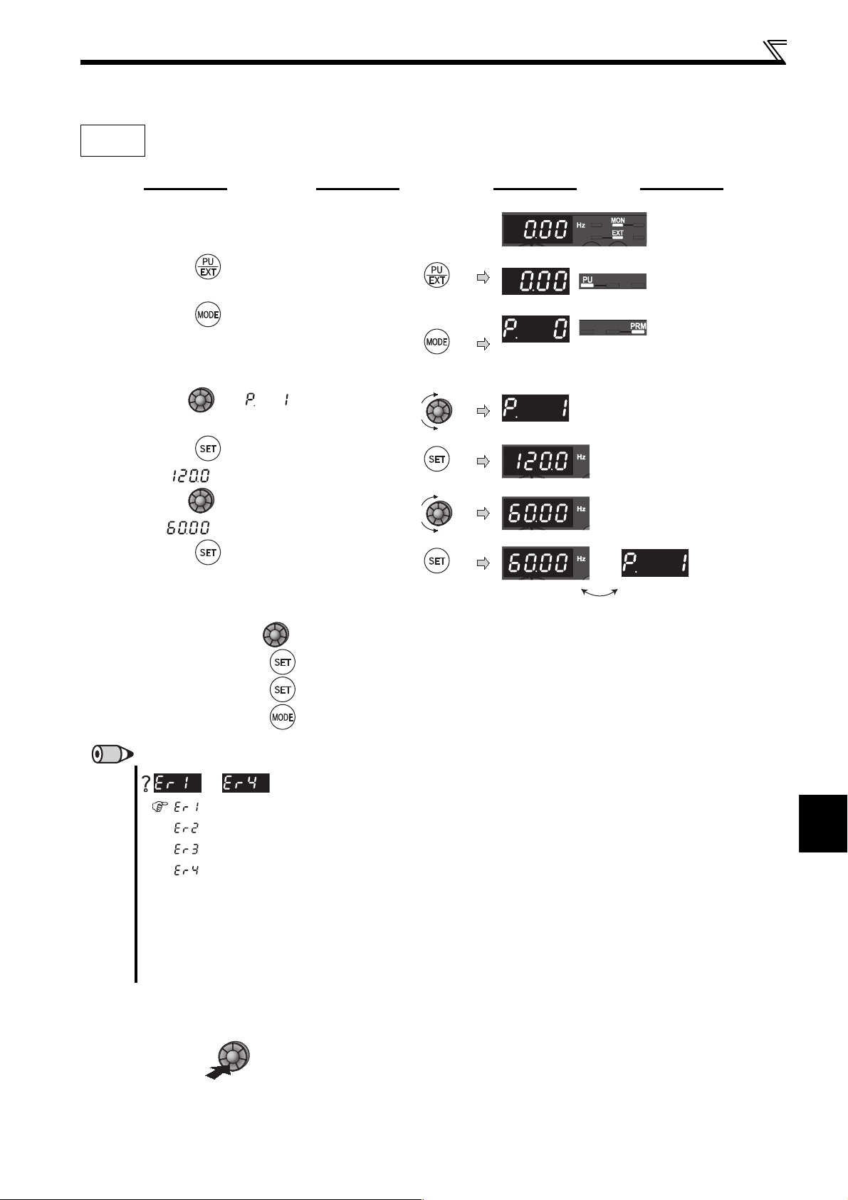
4.1.4 Change the parameter setting value
Operation panel
Changing
example
Change the Pr. 1 Maximum frequency setting.
Operation Display
1.
Screen at powering on
The monitor display appears.
2. Press to choose the PU operation mode.
3. Press to choose the parameter setting
mode.
4. Turn until (Pr. 1) appears.
5. Press to read the present set value.
" "(120.0Hz (initial value)) appears.
6. Turn to change the set value to
" " (60.00Hz).
PU indication is lit.
PRM indication is lit.
(The parameter number read previously
appears.)
7. Press to set.
Flicker...Parameter setting complete!!
Turn to read another parameter.
Press to show the setting again.
Press twice to show the next parameter.
Press twice to return to frequency monitor.
REMARKS
to
appears .................... Write disable error
appears .................... Write error during operation
appears .................... Calibration error
appears .................... Mode designation error
(For details, refer to page 250.)
The number of digits displayed on the operation panel is four. Only the upper four digits of values can be displayed and set. If the
values to be displayed have five digits or more including decimal places, the fifth or later numerals can not be displayed nor set.
(Example) For Pr. 1
When 60Hz is set, 60.00 is displayed.
When 120Hz is set, 120.0 is displayed and second decimal place is not displayed nor set.
is displayed...Why?
4
PARAMETERS
4.1.5 Setting dial push
Push the setting dial ( ) to display the set frequency* currently set.
* Appears when PU operation mode or external/PU combined operation mode 1 is selected (Pr. 79 ="3").
55
Page 67

4.2 Parameter list
V/F
GP
MFVC
4.2.1 Parameter list
For simple variable-speed operation of the inverter, the initial setting of the parameters may be used as they are. Set the
necessary parameters to meet the load and operational specifications. Parameter setting, change and check can be made
from the operation panel. For details of parameters, refer to the instruction manual.
REMARKS
indicates simple mode parameters.
The parameters surrounded by a black border in the table allow its setting to be changed during operation even if "0" (initial
value) is set in Pr. 77 Parameter write selection.
Parameter listParameter list
These instruction codes are used for parameter read and write by using Mitsubishi inverter protocol with the RS-485 communication.
(Refer to page 183 for RS-485 communication)
"" indicates valid and "×" indicates invalid of "control mode-based correspondence table", "parameter copy", "parameter clear", and "all parameter clear".
Parameter List
Func-
Parameter
tion
0 Torque boost 0 to 30% 0.1% 6/4/3% ∗1 73 0 00 80 0 ×
1 Maximum frequency 0 to 120Hz 0.01Hz 120Hz 83 1 01 81 0
2 Minimum frequency 0 to 120Hz 0.01Hz 0Hz 83 2 02 82 0
3 Base frequency 0 to 400Hz 0.01Hz 60Hz 85 3 03 83 0 ×
4 Multi-speed setting (high speed) 0 to 400Hz 0.01Hz 60Hz 89 4 04 84 0
5 Multi-speed setting (middle speed) 0 to 400Hz 0.01Hz 30Hz 89 5 05 85 0
6 Multi-speed setting (low speed) 0 to 400Hz 0.01Hz 10Hz 89 6 06 86 0
7 Acceleration time 0 to 3600s 0.1s 5/10s ∗2 96 7 07 87 0
Basic functions
8 Deceleration time 0 to 3600s 0.1s 5/10s
9 Electronic thermal O/L relay 0 to 500A 0.01A
10 DC injection brake operation frequency 0 to 120Hz 0.01Hz 3Hz 109 10 0A 8A 0
11 DC injection brake operation time 0 to 10s 0.1s 0.5s 109 11 0B 8B 0
brake
DC injection
— 13 Starting frequency 0 to 60Hz 0.01Hz 0.5Hz 98 13 0D 8D 0
— 14 Load pattern selection 0 to 3 1 0 87 14 0E 8E 0 ×
JOG
— 17 MRS input selection 0, 2, 4 1 0 115 17 11 91 0
— 18 High speed maximum frequency 120 to 400Hz 0.01Hz 120Hz 83 18 12 92 0
— 19 Base frequency voltage 0 to 1000V, 8888, 9999 0.1V 9999 85 19 13 93 0 ×
12 DC injection brake operation voltage 0 to 30% 0.1% 6/4%
15 Jog frequency 0 to 400Hz 0.01Hz 5Hz 91 15 0F 8F 0
16 Jog acceleration/deceleration time 0 to 3600s 0.1s 0.5s 91 16 10 90 0
operation
Name Setting Range
Minimum
Setting
Increments
Initial
Value
Rated
inverter
current
Refer
Page
∗2 96 8 08 88 0
∗3 109 12 0C 8C 0
Customer
to
Setting
100 9 09 89 0
Parameter
Remarks
Instruction Code
Read Write
Extended
Control Mode-based
Correspondence Table
GP
MFVC
GP
V/F
V/F
MFVC
Parameter
Copy Clear
All clear
4
Acceleration/
deceleration time
Stall
prevention
setting
Multi-speed
— 29
56
20
22 Stall prevention operation level 0 to 200% 0.1% 150% 79 22 16 96 0
23
24 Multi-speed setting (speed 4) 0 to 400Hz, 9999 0.01Hz 9999 89 24 18 98 0
25 Multi-speed setting (speed 5) 0 to 400Hz, 9999 0.01Hz 9999 89 25 19 99 0
26 Multi-speed setting (speed 6) 0 to 400Hz, 9999 0.01Hz 9999 89 26 1A 9A 0
27 Multi-speed setting (speed 7) 0 to 400Hz, 9999 0.01Hz 9999 89 27 1B 9B 0
Acceleration/deceleration reference
frequency
Stall prevention operation level
compensation factor at double speed
Acceleration/deceleration pattern
selection
1 to 400Hz 0.01Hz 60Hz 96 20 14 94 0
0 to 200%, 9999 0.1% 9999 79 23 17 97 0
0, 1, 2 1 0 99 29 1D 9D 0
PARAMETERS
Page 68

Parameter listParameter list
V/F
GP
MFVC
Func-
Parameter
tion
— 30 Regenerative function selection 0, 1, 2 1 0
31 Frequency jump 1A 0 to 400Hz, 9999 0.01Hz 9999 84 31 1F 9F 0
32 Frequency jump 1B 0 to 400Hz, 9999 0.01Hz 9999 84 32 20 A0 0
33 Frequency jump 2A 0 to 400Hz, 9999 0.01Hz 9999 84 33 21 A1 0
34 Frequency jump 2B 0 to 400Hz, 9999 0.01Hz 9999 84 34 22 A2 0
Frequency jump
— 37 Speed display 0, 0.01 to 9998 0.001 0 127 37 25 A5 0
— 40 RUN key rotation direction selection 0, 1 1 0 237 40 28 A8 0
Frequency
Second functions
35 Frequency jump 3A 0 to 400Hz, 9999 0.01Hz 9999 84 35 23 A3 0
36 Frequency jump 3B 0 to 400Hz, 9999 0.01Hz 9999 84 36 24 A4 0
41 Up-to-frequency sensitivity 0 to 100% 0.1% 10% 123 41 29 A9 0
42 Output frequency detection 0 to 400Hz 0.01Hz 6Hz 123 42 2A AA 0
43
detection
44 Second acceleration/deceleration time 0 to 3600s 0.1s 5/10s ∗2 96, 220 44 2C AC 0
45 Second deceleration time 0 to 3600s, 9999 0.1s 9999 96, 220 45 2D AD 0
46 Second torque boost 0 to 30%, 9999 0.1% 9999 73 46 2E AE 0 ×
47 Second V/F (base frequency) 0 to 400Hz, 9999 0.01Hz 9999 85 47 2F AF 0 ×
48
51 Second electronic thermal O/L relay 0 to 500A, 9999 0.01A 9999 100 51 33 B3 0
52 DU/PU main display data selection
55 Frequency monitoring reference 0 to 400Hz 0.01Hz 60Hz 133 55 37 B7 0
Output frequency detection for reverse
rotation
Second stall prevention operation
current
Name Setting Range
0 to 400Hz, 9999 0.01Hz 9999 123 43 2B AB 0
0 to 200%, 9999 0.1% 9999 79 48 30 B0 0
0, 5, 8 to 12, 14, 20,
23 to 25, 52 to 55, 61,
62, 64, 100
Minimum
Setting
Increments
10128 52 34 B4 0
Initial
Value
Refer
to
Page
110 ,
136
Customer
Setting
Parameter
30 1E 9E 0
Remarks
Read Write
Extended
Instruction Code
Control Mode-based
Correspondence Table
GP
MFVC
GP
V/F
V/F
MFVC
Parameter
Copy Clear
All clear
Parameter List
56 Current monitoring reference 0 to 500A 0.01A
Monitor functions
restart
Automatic
— 59 Remote function selection 0, 1, 2, 3 1 0 93 59 3B BB 0
— 60 Energy saving control selection 0, 9 1 0 147 60 3C BC 0 ×
— 65 Retry selection 0 to 5 1 0 144 65 41 C1 0
—66
Retry
— 70 Special regenerative brake duty 0 to 30% 0.1% 0% 110 70 46 C6 0
— 71 Applied motor
— 72 PWM frequency selection 0 to 15 1 1 148 72 48 C8 0
— 73 Analog input selection 0, 1, 10, 11 1 1 150 73 49 C9 0 ×
— 74 Input filter time constant 0 to 8 1 1 152 74 4A CA 0
— 75
— 77 Parameter write selection 0, 1, 2 1 0 161 77 4D CD ∗4 0
— 78 Reverse rotation prevention selection 0, 1, 2 1 0 162 78 4E CE 0
— 79 Operation mode selection 0, 1, 2, 3, 4, 6, 7 1 0
57 Restart coasting time 0, 0.1 to 5s, 9999 0.1s 9999 136 57 39 B9 0
58 Restart cushion time 0 to 60s 0.1s 1s 136 58 3A BA 0
functions
Stall prevention operation reduction
starting frequency
67 Number of retries at fault occurrence 0 to 10, 101 to 110 1 0 144 67 43 C3 0
68 Retry waiting time 0.1 to 600s 0.1s 1s 144 68 44 C4 0
69 Retry count display erase 0 1 0 144 69 45 C5 0
Reset selection/disconnected PU
detection/PU stop selection
0 to 400Hz 0.01Hz 60Hz 79 66 42 C2 0
0, 1, 3, 13, 23, 40, 43,
50, 53
0 to 3, 14 to 17 1 14 158 75 4B CB 0 × ×
1 0
Rated
inverter
current
133 56 38 B8 0
75,
103,
105,
165,
175
71 47 C7 0
79 4F CF ∗4 0
4
PARAMETERS
58
Page 69

Parameter listParameter list
V/F
GP
MFVC
Func-
Parameter
tion
80 Motor capacity 0.1 to 7.5kW, 9999 0.01kW 9999 75, 105 80 50 D0 0 ×
82 Motor excitation current 0 to 500A, 9999
83 Rated motor voltage 0 to 1000V 0.1V
84 Rated motor frequency 10 to 120Hz 0.01Hz 60Hz 105 84 54 D4 0 ×
90 Motor constant (R1) 0 to 50Ω , 9999 0.001Ω 9999 105 90 5A DA 0 ×
Motor constants
PU connector communication
— 125
— 126
PID operation
PU
— 146 Parameter for manufacturer setting. Do not set. 146 Parameter for manufacturer setting. Do not set.
Current
— 156 Stall prevention operation selection 0 to 31, 100, 101 1 0 79 156 38 B8 1
— 157 OL signal output timer 0 to 25s, 9999 0.1s 0s 79 157 39 B9 1
— 158 AM terminal function selection
— 160 Extended function display selection 0, 9999 1 0 162 160 00 80 2
— 161
96 Auto tuning setting/status 0, 11, 21 1 0
117 PU communication station number 0 to 31 (0 to 247) 1 0
118 PU communication speed 48, 96, 192, 384 1 192
119 PU communication stop bit length 0, 1, 10, 11 1 1 183 11 9 13 93 1 ∗7 ∗7
120 PU communication parity check 0, 1, 2 1 2
121 Number of PU communication retries 0 to 10, 9999 1 1 184 121 15 95 1 ∗7 ∗7
122 PU communication check time interval 0, 0.1 to 999.8s, 9999 0.1s 0
123 PU communication waiting time setting 0 to 150ms, 9999 1 9999 183 123 17 97 1 ∗7 ∗7
124 PU communication CR/LF selection 0, 1, 2 1 1 183 124 18 98 1 ∗7 ∗7
Terminal 2 frequency setting gain
frequency
Terminal 4 frequency setting gain
frequency
127
128 PID action selection 0, 20, 21, 40 to 43 1 0
129 PID proportional band 0.1 to 1000%, 9999 0.1% 100%
130 PID integral time 0.1 to 3600s, 9999 0.1s 1s
131 PID upper limit 0 to 100%, 9999 0.1% 9999
132 PID lower limit 0 to 100%, 9999 0.1% 9999
133 PID action set point 0 to 100%, 9999 0.01% 9999
134 PID differential time 0.01 to 10s, 9999 0.01s 9999
145 PU display language selection 0 to 7 1 1 237 145 2D AD 1 × ×
150 Output current detection level 0 to 200% 0.1% 150% 124 150 32 B2 1
151
152 Zero current detection level 0 to 200% 0.1% 5% 124 152 34 B4 1
detection
153 Zero current detection time 0 to 1s 0.01s 0.5s 124 153 35 B5 1
PID control automatic switchover
frequency
Output current detection signal delay
time
Frequency setting/key lock operation
selection
Name Setting Range
0.01A 9999 105 82 52 D2 0 × ×
0 to 400Hz 0.01Hz 60Hz 153 125 19 99 1 ×
0 to 400Hz 0.01Hz 60Hz 153 126 1A 9A 1 ×
0 to 400Hz, 9999 0.01Hz 9999 212 127 1B 9B 1
0 to 10s 0.1s 0s 124 151 33 B3 1
1 to 3, 5, 8 to 12, 14, 21,
24, 52, 53, 61, 62
0, 1, 10, 11 1 0 238 161 01 81 2 ×
Minimum
Setting
Increments
1 1 128 158 3A BA 1
Initial
Value
200V/400V
∗5
Refer
Page
Customer
to
Setting
105 83 53 D3 0 ×
105,
136
183,
200
183,
200
183,
200
184,
200
212,
220
212,
220
212,
220
212,
220
212,
220
212,
220
212,
220
Parameter
96 60 E0 0 ×
117 11 91 1 ∗7 ∗7
118 12 92 1 ∗7 ∗7
120 14 94 1 ∗7 ∗7
122 16 96 1 ∗7 ∗7
128 1C 9C 1
129 1D 9D 1
130 1E 9E 1
131 1F 9F 1
132 20 A0 1
133 21 A1 1
134 22 A2 1
Remarks
Instruction Code
Read Write
Extended
Control Mode-based
Correspondence Table
GP
MFVC
GP
V/F
V/F
MFVC
Parameter
Copy Clear
All clear
Parameter List
4
PARAMETERS
60
Automatic restart
162
functions
165
Automatic restart after instantaneous
power failure selection
Stall prevention operation level for
restart
0, 1, 10, 11 1 1 136 162 02 82 2
0 to 200% 0.1% 150% 136 165 05 85 2
Page 70

Parameter listParameter list
V/F
GP
MFVC
Func-
Parameter
tion
166
167
Current detection
— 168
— 169 169
170 Watt-hour meter clear 0, 10, 9999 1 9999 128 170 0A 8A 2 ×
Cumulative
Input terminal function
— 240 Soft-PWM operation selection 0, 1 1 1 148 240 30 B0 2
— 241 Analog input display unit switchover 0, 1 1 0 153 241 31 B1 2
— 244 Cooling fan operation selection 0, 1 1 1 228 244 34 B4 2
171 Operation hour meter clear 0, 9999 1 9999 128 171 0B 8B 2 × × ×
monitor clear
178 STF terminal function selection
179 STR terminal function selection
180 RL terminal function selection
assignment
181 RM terminal function selection 1 1 113 181 15 95 2 ×
182 RH terminal function selection 1 2 113 182 16 96 2 ×
190 RUN terminal function selection
192 A,B,C terminal function selection
Output terminal function assignment
232 Multi-speed setting (speed 8) 0 to 400Hz, 9999 0.01Hz 9999 89 232 28 A8 2
233 Multi-speed setting (speed 9) 0 to 400Hz, 9999 0.01Hz 9999 89 233 29 A9 2
234 Multi-speed setting (speed 10) 0 to 400Hz, 9999 0.01Hz 9999 89 234 2A AA 2
235 Multi-speed setting (speed 11) 0 to 400Hz, 9999 0.01Hz 9999 89 235 2B AB 2
236 Multi-speed setting (speed 12) 0 to 400Hz, 9999 0.01Hz 9999 89 236 2C AC 2
237 Multi-speed setting (speed 13) 0 to 400Hz, 9999 0.01Hz 9999 89 237 2D AD 2
238 Multi-speed setting (speed 14) 0 to 400Hz, 9999 0.01Hz 9999 89 238 2E AE 2
Multi-speed setting
239 Multi-speed setting (speed 15) 0 to 400Hz, 9999 0.01Hz 9999 89 239 2F AF 2
245 Rated slip 0 to 50%, 9999 0.01% 9999 78 245 35 B5 2
Output current detection signal
retention time
Output current detection operation
selection
Parameter for manufacturer setting. Do not set.
Name Setting Range
0 to 10s, 9999 0.1s 0.1s 124 166 06 86 2
0, 1 1 0 124 167 07 87 2
0 to 5, 7, 8, 10, 12,
14, 16, 18, 24, 25,
60, 62, 65 to 67, 9999
0 to 5, 7, 8, 10, 12,
14, 16, 18, 24, 25,
61, 62, 65 to 67, 9999
0 to 5, 7, 8, 10, 12,
14, 16, 18, 24, 25,
62, 65 to 67, 9999
0, 1, 3, 4, 7, 8, 11 to 16,
25, 26, 46, 47, 64, 70,
80, 90, 91, 93, 95, 96,
98, 99, 100, 101, 103,
104, 107, 108,
111 to 116, 125, 126,
146, 147, 164, 170, 180,
190, 191, 193, 195,
196, 198, 199, 9999
0, 1, 3, 4, 7, 8, 11 to 16,
25, 26, 46, 47, 64, 70,
80, 90, 91, 95, 96, 98,
99, 100, 101, 103, 104,
107, 108, 111 to 116,
125, 126, 146, 147, 164,
170, 180, 190, 191, 195,
196, 198, 199, 9999
Minimum
Setting
Increments
16011 3 178 12 92 2 ×
1 61 11 3 179 13 93 2 ×
1011 3 180 14 94 2 ×
1 0 119 190 1E 9E 2 ×
19911 9 192 20 A0 2 ×
Initial
Value
Refer
to
Page
Customer
Setting
Parameter
168
Remarks
Instruction Code
Read Write
Parameter for manufacturer setting. Do not set.
Extended
Control Mode-based
Correspondence Table
GP
MFVC
GP
V/F
V/F
MFVC
Parameter
Copy Clear
All clear
Parameter List
4
Slip
— 249 Earth (ground) fault detection at start 0, 1 1 0 146 249 39 B9 2
— 250 Stop selection
— 251 Output phase loss protection selection 0, 1 1 1 146 251 3B BB 2
246 Slip compensation time constant 0.01 to 10s 0.01s 0.5s 78 246 36 B6 2
247
compensation
Constant-power range slip
compensation selection
0, 9999 1 9999 78 247 37 B7 2
0 to 100s,
1000 to 1100s,
8888, 9999
0.1s 9999
112 ,
117
250 3A BA 2
62
PARAMETERS
Page 71

Parameter listParameter list
V/F
GP
MFVC
Func-
Parameter
tion
255 Life alarm status display (0 to 15) 1 0 229 255 3F BF 2 ×××
256 Inrush current limit circuit life display (0 to 100%) 1% 100% 229 256 40 C0 2 × × ×
257 Control circuit capacitor life display (0 to 100%) 1% 100% 229 257 41 C1 2 ×××
258 Main circuit capacitor life display (0 to 100%) 1% 100% 229 258 42 C2 2 × × ×
259 Main circuit capacitor life measuring 0, 1 (2, 3, 8, 9) 1 0 229 259 43 C3 2
Life diagnosis
— 260 PWM frequency automatic switchover 0, 1 1 0 148 260 44 C4 2
261 Power failure stop selection 0, 1, 2 1 0 142 261 45 C5 2
stop
Power failure
— 267 Terminal 4 input selection 0, 1, 2 1 0 150 267 4B CB 2 ×
— 268 Monitor decimal digits selection 0, 1, 9999 1 9999 128 268 4C CC 2
— 269 Parameter for manufacturer setting. Do not set. 269 Parameter for manufacturer setting. Do not set.
— 295 Magnitude of frequency change setting
296 Password lock level 1 to 6, 101 to 106, 9999 1 9999 163 296 68 E8 2 ×
297 Password lock/unlock
function
Password
— 298 Frequency search gain 0 to 32767, 9999 1 9999 136 298 6A EA 2 ×
— 299
338
339
340 Communication startup mode selection 0, 1, 10 1 0 175 340 28 A8 3 ∗7 ∗7
342
343 Communication error count — 1 0 200 343 2B AB 3 × × ×
RS-485 communication
Rotation direction detection selection
at restarting
Communication operation command
source
Communication speed command
source
Communication EEPROM write
selection
Name Setting Range
0, 0.01, 0.10, 1.00,
10.00
1000 to 9999 (0 to 5,
9999)
0, 1, 9999 1 0 136 299 6B EB 2
0, 1 1 0 176 338 26 A6 3 ∗7 ∗7
0, 1, 2 1 0 176 339 27 A7 3 ∗7 ∗7
0, 1 1 0 187 342 2A AA 3
Minimum
Setting
Increments
0.01 0 240 295 67 E7 2
1 9999 163 297 69 E9 2 ×
Initial
Value
Refer
to
Page
Customer
Setting
Parameter
Remarks
Instruction Code
Read Write
Extended
Control Mode-based
Correspondence Table
GP
MFVC
GP
V/F
V/F
MFVC
Parameter
Copy Clear
All clear
Parameter List
450 Second applied motor 0, 1, 9999 1 9999 103 450 32 B2 4
constant
Second motor
495 Remote output selection 0, 1, 10, 11 1 0 126 495 5F DF 4
496 Remote output data 1 0 to 4095 1 0 126 496 60 E0 4 ×××
Output
Remote
— 502
503 Maintenance timer 0 (1 to 9998) 1 0 233 503 03 83 5 ×××
504
Maintenance
549 Protocol selection 0, 1 1 0 200 549 31 B1 5 ∗7 ∗7
551
Communication
555 Current average time 0.1 to 1s 0.1s 1s 234 555 37 B7 5
556 Data output mask time 0 to 20s 0.1s 0s 234 556 38 B8 5
time monitor
Current average
— 561 PTC thermistor protection level 0.5 to 30kΩ , 9999 0.01Ω 9999 100 561 3D BD 5 ×
— 563 Energization time carrying-over times (0 to 65535) 1 0 128 563 3F BF 5 ×××
557
Stop mode selection at communication
error
Maintenance timer alarm output set
time
PU mode operation command source
selection
Current average value monitor signal
output reference current
0, 1, 2 1 0
0 to 9998, 9999 1 9999 233 504 04 84 5 ×
2, 4, 9999 1 9999 176 551 33 B3 5 ∗7 ∗7
0 to 500A 0.01A
Rated
inverter
current
184,
200
234 557 39 B9 5
502 02 82 5
4
PARAMETERS
64
Page 72

Parameter listParameter list
V/F
GP
MFVC
Func-
tion
Parameter
Name Setting Range
Minimum
Setting
Increments
Initial
Value
Refer
to
Page
Customer
Setting
Parameter
Remarks
Instruction Code
Read Write
Extended
Control Mode-based
Correspondence Table
GP
MFVC
GP
V/F
V/F
MFVC
Parameter
Copy Clear
All clear
— 564 Operating time carrying-over times (0 to 65535) 1 0 128 564 40 C0 5 × × ×
— 571 Holding time at a start 0 to 10s, 9999 0.1s 9999 98 571 47 C7 5
575 Output interruption detection time 0 to 3600s, 9999 0.1s 1s 212 575 4B CB 5
PID
576 Output interruption detection level 0 to 400Hz 0.01Hz 0Hz 212 576 4C CC 5
operation
577 Output interruption cancel level 900 to 1100% 0.1% 1000% 212 577 4D CD 5
— 611 Acceleration time at a restart 0 to 3600s, 9999 0.1s 9999 136 611 0B 8B 6
— 653 Speed smoothing control 0 to 200% 0.1% 0 149 653 35 B5 6
— 665
Regeneration avoidance frequency
gain
0 to 200% 0.1% 100 226 665 41 C1 6
872 ∗8 Input phase loss protection selection 0, 1 1 0 146 872 48 C8 8
functions
Protective
882
883
885
function
Regeneration avoidance operation
selection
Regeneration avoidance operation
level
Regeneration avoidance compensation
frequency limit value
0, 1, 2 1 0 226 882 52 D2 8
300 to 800V 0.1V
400VDC/
780VDC
226 883 53 D3 8
∗5
0 to 10Hz, 9999 0.01Hz 6Hz 226 885 55 D5 8
886 Regeneration avoidance voltage gain 0 to 200% 0.1% 100% 226 886 56 D6 8
Regeneration avoidance
Parameter List
888 Free parameter 1 0 to 9999 1 9999 236 888 58 D8 8 ××
Free
889 Free parameter 2 0 to 9999 1 9999 236 889 59 D9 8 × ×
parameter
— 891
C1
(901)
C2
(902)
C3
(902)
125
(903)
C4
(903)
C5
(904)
Calibration parameters
C6
(904)
126
(905)
C7
(905)
C22 to C25
—
(922 to 923)
990 PU buzzer control 0, 1 1 1 241 990 5A DA 9
PU
991 PU contrast adjustment 0 to 63 1 58 241 991 5B DB 9 ×
Cumulative power monitor digit shifted
times
AM terminal calibration — — — 134
∗6
Terminal 2 frequency setting bias
frequency
∗6
Terminal 2 frequency setting bias 0 to 300% 0.1% 0% 153
∗6
Terminal 2 frequency setting gain
frequency
∗6
Terminal 2 frequency setting gain 0 to 300% 0.1% 100% 153
∗6
Terminal 4 frequency setting bias
frequency
∗6
Terminal 4 frequency setting bias 0 to 300% 0.1% 20% 153
∗6
Terminal 4 frequency setting gain
frequency
∗6
Terminal 4 frequency setting gain 0 to 300% 0.1% 100% 153
∗6
0 to 4, 9999 1 9999 128 891 5B D8 8
0 to 400Hz 0.01Hz 0Hz 153
0 to 400Hz 0.01Hz 60Hz 153
0 to 400Hz 0.01Hz 0Hz 153
0 to 400Hz 0.01Hz 60Hz 153
Parameter for manufacturer setting. Do not set.
C1
(901)
C2
(902)
C3
(902)
125
(903)
C4
(903)
C5
(904)
C6
(904)
126
(905)
C7
(905)
C22 to C25
(922 to 923)
5D DD 1 ×
5E DE 1 ×
5E DE 1 ×
5F DF 1 ×
5F DF 1 ×
60 E0 1 ×
60 E0 1 ×
61 E1 1 ×
61 E1 1 ×
Parameter for manufacturer setting. Do not set.
4
PARAMETERS
66
Page 73

Parameter listParameter list
V/F
GP
MFVC
Func-
tion
Parameter
Name Setting Range
Minimum
Setting
Increments
Initial
Value
Refer
to
Page
Customer
Setting
Pr.CL Parameter clear 0, 1 1 0 242 Pr.CL — — — — — — — —
ALLC All parameter clear 0, 1 1 0 242 ALLC ——— — — — — —
Er.CL Faults history clear 0, 1 1 0 244 Er.CL — — — — — — — —
Clear parameters
Pr.CH Initial value change list — — — 243 Pr.CH ——— — — — — —
Initial value change list
∗1 Differ according to capacities.
6%: FR-D720-042 or less, FR-D740-022 or less, FR-D720S-042 or less
4%: FR-D720-070 to 165, FR-D740-036 to 080, FR-D720S-070 and 100
3%: FR-D720-238 and 318, FR-D740-120 and 160
∗2 Differ according to capacities.
5s: FR-D720-165 or less, FR-D740-080 or less, FR-D720S-008 to 100
10s: FR-D720-238 and 318, FR-D740-120 and 160
∗3 Differ according to capacities.
6%: FR-D720-008 and 014, FR-D720S-008 and 014
4%: FR-D720-025 or more, FR-D740-012 or more, FR-D720S-025 or more
∗4 Write is disabled in the communication mode (network operation mode) from the PU connector.
∗5 The initial value differs according to the voltage class. (200V class, 400V class)
∗6 The parameter number in parentheses is the one for use with the operation panel (PA02) for the FR-E500 series or parameter unit (FR-PU04/FR-PU07).
∗7 These parameters are communication parameters that are not cleared when parameter clear (all clear) is executed from RS-485 communication. (Refer to
page 180 for RS-485 communication)
∗8 Available only for the three-phase power input specification model.
Parameter
Remarks
Instruction Code
Read Write
Extended
Control Mode-based
Correspondence Table
GP
MFVC
GP
V/F
V/F
MFVC
Parameter
Copy Clear
All clear
Parameter List
4
PARAMETERS
68
Page 74

Parameters according to purposes
4.3 Adjust the output torque (current) of the motor 73
4.3.1 Manual torque boost (Pr. 0, Pr. 46) .............................................................................................. 73
4.3.2 Large starting torque and low speed torque are necessary (General-purpose magnetic flux vector
control (Pr. 71, Pr. 80)) ................................................................................................................. 75
4.3.3 Slip compensation (Pr. 245 to Pr. 247)......................................................................................... 78
4.3.4 Stall prevention operation (Pr. 22, Pr. 23, Pr. 48, Pr. 66, Pr. 156, Pr. 157) .................................. 79
4.4 Limit the output frequency 83
4.4.1 Maximum/minimum frequency (Pr. 1, Pr. 2, Pr. 18)...................................................................... 83
4.4.2 Avoid mechanical resonance points (frequency jumps) (Pr. 31 to Pr. 36).................................... 84
4.5 Set V/F pattern 85
4.5.1 Base frequency, voltage (Pr. 3, Pr. 19, Pr. 47) ............................................................................. 85
4.5.2 Load pattern selection (Pr. 14) ..................................................................................................... 87
4.6 Frequency setting by external terminals 89
4.6.1 Operation by multi-speed operation (Pr. 4 to Pr. 6, Pr. 24 to Pr. 27, Pr. 232 to Pr. 239).............. 89
4.6.2 Jog operation (Pr. 15, Pr. 16) ....................................................................................................... 91
4.6.3 Remote setting function (Pr. 59) ................................................................................................... 93
4.7 Setting of acceleration/deceleration time and acceleration/
deceleration pattern 96
4.7.1 Setting of the acceleration and deceleration time
(Pr. 7, Pr. 8, Pr. 20, Pr. 44, Pr. 45) .............................................................................................. 96
4.7.2 Starting frequency and start-time hold function (Pr. 13, Pr. 571).................................................. 98
4.7.3 Acceleration/deceleration pattern (Pr. 29) .................................................................................... 99
4.8 Selection and protection of a motor 100
4.8.1 Motor overheat protection (Electronic thermal O/L relay, PTC thermistor protection) (Pr. 9, Pr. 51,
Pr. 561) ....................................................................................................................................... 100
4.8.2 Applied motor (Pr. 71, Pr. 450) ................................................................................................... 103
4.8.3 To exhibit the best performance of the motor (offline auto tuning)
(Pr. 71, Pr. 80, Pr. 82 to Pr. 84, Pr. 90, Pr. 96) ........................................................................... 105
4.9 Motor brake and stop operation 109
4.9.1 DC injection brake (Pr. 10 to Pr. 12)........................................................................................... 109
4.9.2 Selection of a regenerative brake (Pr. 30, Pr. 70) ...................................................................... 110
4.9.3 Stop selection (Pr. 250) .............................................................................................................. 112
4.10 Function assignment of external terminal and control 113
4.10.1 Input terminal function selection (Pr. 178 to Pr. 182).................................................................. 113
4.10.2 Inverter output shutoff signal (MRS signal, Pr. 17) ..................................................................... 115
4.10.3 Condition selection of function validity by second function selection signal (RT) ....................... 116
4.10.4 Start signal operation selection (STF, STR, STOP signal, Pr. 250) ........................................... 117
4.10.5 Output terminal function selection (Pr. 190, Pr. 192).................................................................. 119
4.10.6 Detection of output frequency (SU, FU signal, Pr. 41 to Pr. 43)................................................. 123
4.10.7 Output current detection function
(Y12 signal, Y13 signal, Pr. 150 to Pr. 153, Pr. 166, Pr. 167) .................................................... 124
70
Page 75

4.10.8 Remote output selection (REM signal, Pr. 495, Pr. 496)............................................................ 126
4.11 Monitor display and monitor output signal 127
4.11.1 Speed display and speed setting (Pr. 37)................................................................................... 127
4.11.2 Monitor display selection of operation panel/PU and terminal AM
(Pr. 52, Pr.158, Pr. 170, Pr. 171, Pr. 268, Pr. 563, Pr. 564, Pr. 891) ......................................... 128
4.11.3 Reference of the terminal AM (analog voltage output) (Pr. 55, Pr. 56) ...................................... 133
4.11.4 Terminal AM calibration (calibration parameter C1 (Pr.901)) ..................................................... 134
4.12 Operation selection at power failure and instantaneous power
failure 136
4.12.1 Automatic restart after instantaneous power failure/flying start
(Pr. 30, Pr. 57, Pr. 58, Pr. 96, Pr. 162, Pr. 165, Pr. 298, Pr. 299, Pr. 611) ................................. 136
4.12.2 Power-failure deceleration stop function (Pr. 261) ..................................................................... 142
4.13 Operation setting at fault occurrence 144
4.13.1 Retry function (Pr. 65, Pr. 67 to Pr. 69) ...................................................................................... 144
4.13.2 Input/output phase loss protection selection (Pr. 251, Pr. 872) .................................................. 146
4.13.3 Earth (ground) fault detection at start (Pr. 249) .......................................................................... 146
4.14 Energy saving operation 147
4.14.1 Optimum excitation control (Pr. 60) ............................................................................................ 147
4.15 Motor noise, EMI measures, mechanical resonance 148
4.15.1 PWM carrier frequency and Soft-PWM control (Pr. 72, Pr. 240, Pr. 260)................................... 148
4.15.2 Speed smoothing control (Pr. 653)............................................................................................. 149
4.16 Frequency setting by analog input (terminal 2, 4) 150
4.16.1 Analog input selection (Pr. 73, Pr. 267)...................................................................................... 150
4.16.2 Response level of analog input and noise elimination (Pr. 74)................................................... 152
4.16.3 Bias and gain of frequency setting voltage (current)
(Pr. 125, Pr. 126, Pr. 241, C2 (Pr. 902) to C7 (Pr. 905)) ............................................................ 153
4.17 Misoperation prevention and parameter setting restriction 158
4.17.1 Reset selection/disconnected PU detection/PU stop selection (Pr. 75) ..................................... 158
4.17.2 Parameter write disable selection (Pr. 77).................................................................................. 161
4.17.3 Reverse rotation prevention selection (Pr. 78) ........................................................................... 162
4.17.4 Extended parameter display (Pr. 160)........................................................................................ 162
4.17.5 Password function (Pr. 296, Pr. 297).......................................................................................... 163
4.18 Selection of operation mode and operation location 165
Parameters according to purposes
4
4.18.1 Operation mode selection (Pr. 79).............................................................................................. 165
4.18.2 Operation mode at power-on (Pr. 79, Pr. 340) ........................................................................... 175
4.18.3 Start command source and frequency command source during communication
operation (Pr. 338, Pr. 339, Pr. 551) .......................................................................................... 176
4.19 Communication operation and setting 180
4.19.1 Wiring and configuration of PU connector .................................................................................. 180
4.19.2 Initial settings and specifications of RS-485 communication
(Pr. 117 to Pr. 120, Pr. 123, Pr. 124, Pr. 549) ............................................................................ 183
71
PARAMETERS
Page 76

4.19.3 Operation selection at communication error occurrence (Pr. 121, Pr. 122, Pr. 502) .................. 184
4.19.4 Communication EEPROM write selection (Pr. 342) ................................................................... 187
4.19.5 Mitsubishi inverter protocol (computer link communication)....................................................... 188
4.19.6 Modbus RTU communication specifications
(Pr. 117, Pr. 118, Pr. 120, Pr. 122, Pr. 343, Pr. 502, Pr. 549) .................................................... 200
4.20 Special operation and frequency control 212
4.20.1 PID control (Pr. 127 to Pr. 134, Pr. 575 to Pr. 577) .................................................................... 212
4.20.2 Dancer control (Pr. 44, Pr. 45, Pr. 128 to Pr. 134)...................................................................... 220
4.20.3 Regeneration avoidance function (Pr. 665, Pr. 882, Pr. 883, Pr. 885, Pr. 886).......................... 226
4.21 Useful functions 228
4.21.1 Cooling fan operation selection (Pr. 244) ................................................................................... 228
4.21.2 Display of the life of the inverter parts (Pr. 255 to Pr. 259)......................................................... 229
4.21.3 Maintenance timer alarm (Pr. 503, Pr. 504)................................................................................ 233
4.21.4 Current average value monitor signal (Pr. 555 to Pr. 557) ......................................................... 234
4.21.5 Free parameter (Pr. 888, Pr. 889) .............................................................................................. 236
4.22 Setting the parameter unit and operation panel 237
4.22.1 RUN key rotation direction selection (Pr. 40).............................................................................. 237
4.22.2 PU display language selection(Pr.145)....................................................................................... 237
4.22.3 Operation panel frequency setting/key lock operation selection (Pr. 161).................................. 238
4.22.4 Magnitude of frequency change setting (Pr. 295)....................................................................... 240
4.22.5 Buzzer control (Pr. 990).............................................................................................................. 241
4.22.6 PU contrast adjustment (Pr. 991) ............................................................................................... 241
4.23 Parameter clear/ All parameter clear 242
4.24 Initial value change list 243
4.25 Check and clear of the faults history 244
72
Page 77

Adjust the output torque (current) of the motor
V/F
P
P
4.3 Adjust the output torque (current) of the motor
Purpose Parameter that should be Set Refer to Page
Set starting torque manually Manual torque boost Pr. 0, Pr. 46
Automatically control output current
according to load
Compensate for motor slip to secure
low-speed torque
Limit output current to prevent
inverter trip
4.3.1 Manual torque boost (Pr. 0, Pr. 46)
Motor torque reduction in the low-speed range can be improved by compensating a voltage drop in the low-frequency range.
Motor torque in the low-frequency range can be adjusted to the load to increase the starting motor torque.
Two kinds of start torque boosts can be changed by switching between terminals.
General-purpose magnetic
flux vector control
Pr. 71, Pr. 80
Slip compensation Pr. 245 to Pr. 247
Stall prevention operation
V/F
V/F
Pr. 22, Pr. 23, Pr. 66, Pr. 156,
Pr. 157
73
75
78
79
Parameter
Number
0 Torque boost
46 ∗
* The above parameters can be set when Pr. 160 Extended function display selection = "0". (Refer to page 162)
Name Initial Value
FR-D720-042 or less
FR-D740-022 or less
FR-D720S-008 to 042
FR-D720-070 to 165
FR-D740-036 to 080
FR-D720S-070 and 100
FR-D720-238 and 318
FR-D740-120 and 160
Second torque
boost
6%
4%
3%
9999
Setting
Range
0 to 30% Set the output voltage at 0Hz as %.
0 to 30% Set the torque boost when the RT signal is on.
9999 Without second torque boost
Description
(1) Starting torque adjustment
On the assumption that Pr. 19 Base frequency voltage is 100%, set
the output voltage at 0Hz in % to Pr. 0 (Pr. 46).
Adjust the parameter little by little (about 0.5%), and check the
motor status each time. If the setting is too large, the motor will
overheat. The guideline is about 10% at the greatest.
r. 0
Setting range
r. 46
(2) Set two kinds of torque boosts (RT signal, Pr. 46)
When you want to change torque boost according to applications, switch multiple motors with one inverter, etc., use Second
torque boost.
Pr. 46 Second torque boost is valid when the RT signal is on.
For the terminal used for RT signal input, set "3" in any of Pr. 178 to Pr. 182 (input terminal function selection) to assign the function.
100%
Output voltage
0
Output frequency (Hz)
Base frequency
REMARKS
The RT signal acts as the second function selection signal and makes the other second functions valid. (Refer to page 116)
4
PARAMETERS
73
Page 78

Adjust the output torque (current) of the motor
NOTE
The amount of current flows in the motor may become large according to the conditions such as the motor
characteristics, load, acceleration/deceleration time, wiring length, etc., resulting in an overcurrent trip (OL (overcurrent
alarm) then E.OC1 (overcurrent trip during acceleration), overload trip (E.THM (motor overload trip), or E.THT (inverter
overload trip).
(When a fault occurs, release the start command, and decrease the Pr. 0 setting 1% by 1% to reset.) (Refer to page 248.)
The Pr. 0, Pr. 46 settings are valid only when V/F control is selected.
When using the inverter dedicated motor (constant torque motor) with the FR-D720-238 and 318, FR-D740-120 and 160, set torque
boost value to 2%.
Pr. 0
When
changes to 2%.
= "3%"(initial value), if
Changing the terminal assignment using Pr. 178 to Pr. 182 (input terminal function selection) may affect the other
functions. Make setting after confirming the function of each terminal.
Parameters referred to
Pr. 3 Base frequency, Pr. 19 Base frequency voltage Refer to page 85
Pr. 71 Applied motor Refer to page 103
Pr. 178 to Pr. 182 (input terminal function selection) Refer to page 113
Pr. 71
value is changed to the setting for use with a constant-torque motor, the
Pr. 0
setting
74
Page 79

Adjust the output torque (current) of the motor
GP
MFVC
4.3.2 Large starting torque and low speed torque are necessary (General-purpose
GP
MFVC
GP
magnetic flux vector control (Pr. 71, Pr. 80))
General-purpose magnetic flux vector control is available.
Large starting torque and low speed torque are available with General-purpose magnetic flux vector control.
What is General-purpose magnetic flux vector control ?
The low speed torque can be improved by providing voltage compensation to flow a motor current which meets the
load torque. With setting slip compensation (Pr. 245 to Pr. 247), output frequency compensation (slip compensation) is
made so that the actual motor speed goes closer to a speed command value. Effective when load fluctuates
drastically, etc.
General-purpose magnetic flux vector control is the same function as the FR-E500 series.
MFVC
Parameter
Number
Name
71 Applied motor
80 Motor capacity
The above parameters can be set when Pr. 160 Extended function display selection = "0". (Refer to page 162)
Initial
Value
0
9999
Setting Range Description
0,1, 3,
13, 23, 40, 43
50, 53
0.1 to 7.5kW
9999 V/F control
By selecting a standard motor or constant torque motor,
thermal characteristic and motor constants of each motor
are set.
Applied motor capacity. (General-purpose magnetic flux
vector control)
POINT
If the following conditions are not satisfied, select V/F control since malfunction such as insufficient torque and
uneven rotation may occur.
The motor capacity should be equal to or one rank lower than the inverter capacity. (note that the capacity
should be 0.1kW or more)
Motor to be used is any of Mitsubishi standard motor, high efficiency motor (SF-JR, SF-HR 0.2kW or more) or
Mitsubishi constant torque motor (SF-JRCA four-pole, SF-HRCA 0.4kW to 7.5kW). When using a motor other
than the above (other manufacturer's motor), perform offline auto tuning without fail.
Single-motor operation (one motor run by one inverter) should be performed.
The wiring length from inverter to motor should be within 30m (98.42feet). (Perform offline auto tuning in the
state where wiring work is performed when the wiring length exceeds 30m (98.42feet).)
Permissible wiring length between inverter and motor differs according to the inverter capacity and setting value
of Pr. 72 PWM frequency selection (carrier frequency). Refer to page 19 for the permissible wiring length.
(1) Control mode
V/F control (initial setting) and General-purpose magnetic flux vector control are available with this inverter.
V/F control is for controlling frequency and voltage so that the ratio of frequency (F) to voltage (V) is constant when
changing frequency.
General-purpose magnetic flux vector control divides the inverter output current into an excitation current and a torque
current by vector calculation, and makes voltage compensation to flow a motor current which meets the load torque.
(General-purpose magnetic flux vector control is the same function as the FR-E500 series.)
75
4
PARAMETERS
Page 80

Adjust the output torque (current) of the motor
(2) Selection method of General-purpose magnetic flux vector control
Perform secure wiring.
(Refer to page 14)
Display the extended function parameters.
(Pr. 160) (Refer to page 162)
Set "0" in Pr. 160 to display the extended function parameters.
Set the motor. (Pr. 71)
Motor Pr. 71 Setting ∗1 Remarks
Mitsubishi standard
motor
Mitsubishi high
efficiency motor
Mitsubishi constanttorque motor
Other standard motor
Other constanttorque motor
∗1 Refer to page 103 for other settings of Pr. 71.
∗2 Refer to page 105 for offline auto tuning.
SF-JR 0 (initial value)
SF-HR 40
Others 3
SF-JRCA 4P 1
SF-HRCA 50
Others (SF-JRC, etc.) 13
—
—
3
13
Offline auto tuning is necessary. ∗2
Offline auto tuning is necessary. ∗2
Offline auto tuning is necessary. ∗2
Offline auto tuning is necessary. ∗2
Set the motor capacity.
(Pr. 80) (Refer to page 74)
Set motor capacity (kW) in Pr. 80 Motor capacity.
(V/F control is performed when the setting is "9999" (initial value).
Set the operation command. (Refer to page 165)
Select the start command and speed command.
(1)Start command
1)Operation panel: Setting by pressing of the operation panel
2)External command: Setting by forward rotation or reverse rotation
command (terminal STF or STR)
(2)Speed command
1)Operation panel: Setting by turning of the operation panel
2)External analog command (terminal 2 or 4):
Give a speed command using the analog signal input to terminal 2 (or
terminal 4).
3)Multi-speed command:
The external signals (RH, RM, RL) may also be used to give speed
command.
Test r un
As required
Perform offline auto tuning. (Pr. 96) (Refer to page 105)
Set motor excitation current. (Pr. 82) (Refer to page 105)
Set slip compensation. (Pr. 245, Pr. 246, Pr. 247) (Refer to page 78)
76
NOTE
Uneven rotation slightly increases as compared to the V/F control. (It is not suitable for machines such as grinding
machine and wrapping machine which requires less uneven rotation at low speed.)
When a surge voltage suppression filter (FR-ASF-H/FR-BMF-H) is connected between the inverter and motor, output
torque may decrease.
Page 81

Adjust the output torque (current) of the motor
(3) Control method switching by external terminals (X18 signal)
Use the V/F switchover signal (X18) to change the control method (V/F control and General-purpose magnetic flux vector
control) with external terminal.
Turn the X18 signal on to change the currently selected control method (General-purpose magnetic flux vector control) to
V/F control.
For the terminal used for X18 signal input, set "18" in any of Pr. 178 to Pr. 182 (input terminal function selection) to assign the
function.
REMARKS
When V/F control is selected by V/F switchover (X18 signal), second function is also selected at the same time. Control between
V/F control and General-purpose magnetic flux vector control can not be switched while the inverter is running. In case control is
switched between V/F control and General-purpose magnetic flux vector control, only second function is selected.
NOTE
Changing the terminal assignment using Pr. 178 to Pr. 182 (input terminal function selection) may affect the other
functions. Make setting after confirming the function of each terminal.
Parameters referred to
Pr.3 Base frequency, Pr.19 Base frequency voltage Refer to page 85
Pr.71 Applied motor Refer to page 103
Pr.77 Parameter write selection Refer to page 161
Pr. 178 to Pr. 182 (input terminal function selection) Refer to page 113
77
4
PARAMETERS
Page 82
Adjust the output torque (current) of the motor
4.3.3 Slip compensation (Pr. 245 to Pr. 247)
Inverter output current may be used to assume motor slip to keep the motor speed constant.
Parameter
Number
245 Rated slip
246
Slip compensation time
constant
Constant-power range
247
slip compensation
selection
The above parameters can be set when Pr. 160 Extended function display selection = "0". (Refer to page 162)
Slip compensation is validated when the motor rated slip calculated by the following formula is set in Pr. 245. Slip
Name Initial Value Setting Range Description
9999
0.5s 0.01 to 10s
9999
0.01 to 50% Rated motor slip
0, 9999 No slip compensation
Slip compensation response time. When the
value is made smaller, response will be faster.
However, as load inertia is greater, a
regenerative overvoltage fault (E.OV) is more
liable to occur.
Slip compensation is not made in the constant
0
9999
power range. (frequency range above the
frequency set in Pr. 3)
Slip compensation is made in the constant power
range.
compensation is not made when Pr. 245 = "0" or "9999".
Rated slip
=
Synchronous speed at base frequency
× 100[%]
Synchronous speed at base frequency - rated speed
REMARKS
When performing slip compensation, the output frequency may become greater than the set frequency. Set the Pr. 1 Maximum
frequency value a little higher than the set frequency.
Parameters referred to
Pr. 1 Maximum frequency Refer to page 83
Pr. 3 Base frequency Refer to page 85
78
Page 83
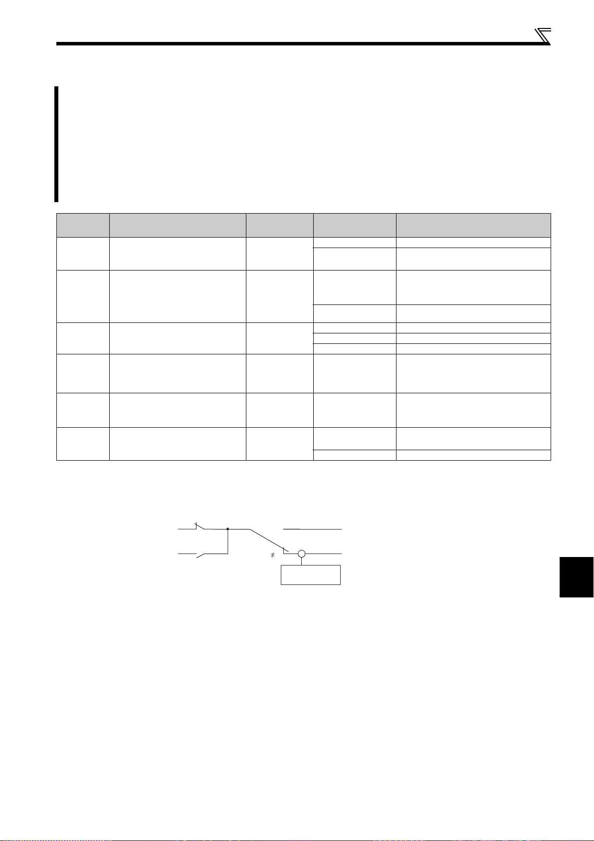
Adjust the output torque (current) of the motor
P
P
4.3.4 Stall prevention operation (Pr. 22, Pr. 23, Pr. 48, Pr. 66, Pr. 156, Pr. 157)
This function monitors the output current and automatically changes the output frequency to prevent the inverter from
coming to trip due to overcurrent, overvoltage, etc.
It can also limit stall prevention and fast-response current limit operation during acceleration/deceleration, driving or
regeneration.
Stall prevention
If the output current exceeds the stall prevention operation level, the output frequency of the inverter is
automatically changed to reduce the output current.
Fast-response current limit
If the current exceeds the limit value, the output of the inverter is shut off to prevent an overcurrent.
Parameter
Number
22
Stall prevention operation
level
Name Initial Value Setting Range Description
0 Stall prevention operation invalid
150%
0.1 to 200%
Stall prevention
23
48
operation level
compensation factor
at double speed
Second stall prevention
operation current
9999
9999
0 to 200%
9999 Constant according to Pr. 22.
0 Stall prevention operation invalid
0.1 to 200% Second stall prevention operation level
9999 Same level as Pr. 22.
Stall prevention
66
operation reduction
60Hz 0 to 400Hz
starting frequency
156
Stall prevention operation
selection
157 OL signal output timer
The above parameters can be set when Pr. 160 Extended function display selection = "0". (Refer to page 162)
0 0 to 31, 100, 101
0s
0 to 25s
9999 Without the OL signal output
(1) Block diagram
Set the current value to start the stall
prevention operation.
The stall operation level can be reduced
when operating at a high speed above the
rated frequency.
Set the frequency at which the stall
operation level is started to reduce.
Select whether stall prevention operation
and fast-response current limit operation
will be performed or not.
Output start time of the OL signal output
when stall prevention is activated.
r. 22
r. 48
RT
RT
= 0
+
0
-
Output frequency
Pr. 23, Pr. 66
Stall prevention operation invalid
Stall prevention operation level
4
PARAMETERS
79
Page 84
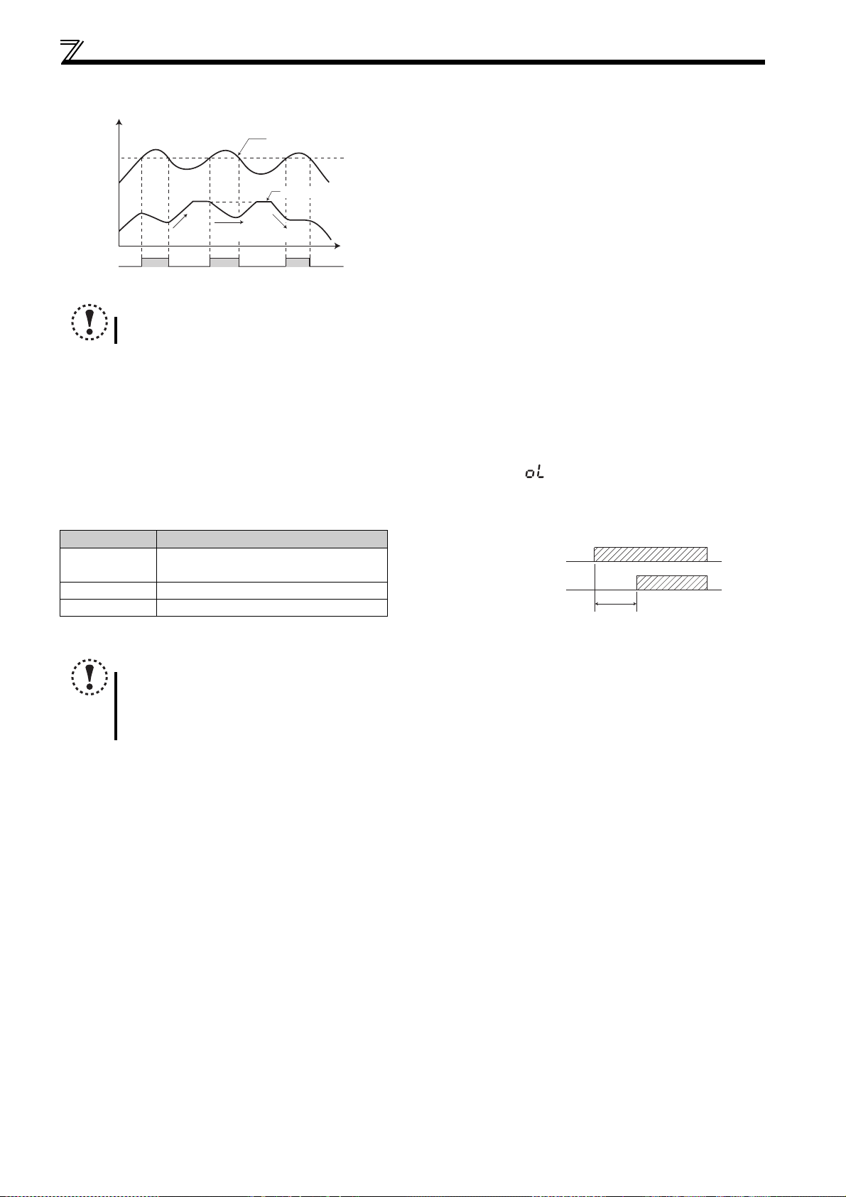
Adjust the output torque (current) of the motor
P
(2) Setting of stall prevention operation level (Pr. 22)
Set in Pr. 22 the percentage of the output current to the rated
Output current
r. 22
Output frequency
Deceleration
Constant
Acceleration
speed
OL
Stall prevention operation example
Time
NOTE
If an overload status lasts long, an inverter trip (e.g. electronic thermal O/L relay (E.THM)) may occur.
(3) Stall prevention operation signal output and output timing adjustment (OL signal, Pr. 157)
When the output current exceeds the stall prevention operation level and stall prevention is activated, the stall prevention
operation signal (OL signal) turns on for longer than 100ms. When the output current falls to or below the stall prevention
operation level, the output signal turns off.
Use Pr. 157 OL signal output timer to set whether the OL signal is output immediately or after a preset period of time.
This operation is also performed when the regeneration avoidance function or (overvoltage stall) is executed.
For the OL signal, set "3 (positive logic) or 103 (negative logic)" in Pr. 190 or Pr. 192 (output terminal function selection) and
assign functions to the output terminal.
inverter current at which stall prevention operation will be
performed. Normally set this parameter to 150% (initial value).
Stall prevention operation stops acceleration (makes
deceleration) during acceleration, makes deceleration during
constant speed, and stops deceleration (makes acceleration)
during deceleration.
When stall prevention operation is performed, the OL signal is
output.
Pr. 157 Setting Description
0
(initial value)
0.1 to 25 Output after the set time (s) has elapsed.
9999 Not output.
Output immediately.
NOTE
If the frequency has fallen to 1Hz by stall prevention operation and remains for 3s, a fault (E.OLT) appears to trip the
inverter output.
Changing the terminal assignment using Pr. 190, Pr. 192 (output terminal function selection) may affect the other functions.
Make setting after confirming the function of each terminal.
Overload state (OL operation)
OL output signal
Pr. 157 set time(s)
80
Page 85
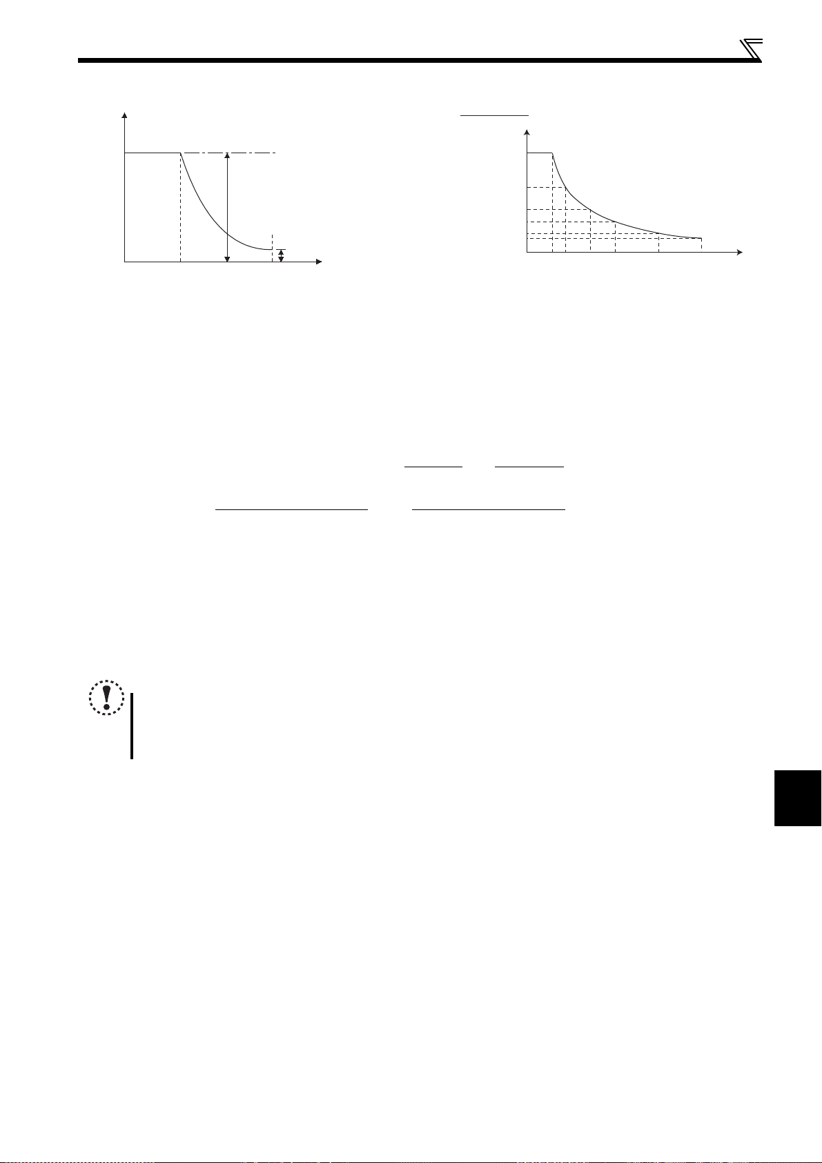
Adjust the output torque (current) of the motor
(4) Setting of stall prevention operation in high frequency range (Pr. 22, Pr. 23, Pr. 66)
Pr. 22
Stall prevention operation
level (%)
When Pr. 23 = 9999
Pr. 66
When Pr. 23 = "9999", the stall prevention
operation level is as set in Pr. 22 to 400Hz.
Stall prevention operation level
as set in Pr. 23
400Hz
Output frequency (Hz)
Setting example
Stall prevention
(Pr. 22 = 150%, Pr. 23 = 100%, Pr. 66 = 60Hz)
(%)
150
90
60
operation level
45
30
22.5
0 10060 200150 300 400
Output frequency (Hz)
During high-speed operation above the rated motor frequency, acceleration may not be made because the motor current
does not increase. If operation is performed in a high frequency range, the current at motor lockup becomes smaller than
the rated output current of the inverter, and the protective function (OL) is not executed even if the motor is at a stop.
To improve the operating characteristics of the motor in this case, the stall prevention level can be reduced in the high
frequency range. This function is effective for performing operation up to the high-speed range on a centrifugal separator,
etc. Normally, set 60Hz in Pr. 66 and 100% in Pr. 23.
Formula for stall prevention operation level
Stall prevention operation level
in high frequency range (%)
However, A =
Pr. 66 (Hz) × Pr. 22 (%)
Output frequency (Hz)
=A + B × [
,B=
Pr. 22 - A
Pr. 22 - B
Pr. 66 (Hz) × Pr. 22 (%)
] × [
400Hz
Pr. 23 - 100
100
]
By setting "9999" (initial value) in Pr. 23 Stall prevention operation level compensation factor at double speed, the stall
prevention operation level is constant at the Pr. 22 setting up to 400Hz.
(5) Set two types of stall prevention operation levels (Pr. 48)
Turning RT signal on makes Pr. 48 Second stall prevention operation current valid.
For the terminal used for RT signal input, set "3" in any of Pr. 178 to Pr. 182 (input terminal function selection) to assign the
function.
NOTE
Changing the terminal assignment using Pr. 178 to Pr. 182 (input terminal function selection) may affect the other
functions. Make setting after confirming the function of each terminal.
The RT signal acts as the second function selection signal and makes the other second functions valid.
(Refer to page 116)
4
PARAMETERS
81
Page 86

Adjust the output torque (current) of the motor
(6) Limit the stall prevention operation and fast-response current limit operation according to the
operating status (Pr. 156)
Refer to the following table and select whether stall prevention operation and fast-response current limit operation will be
performed or not and the operation to be performed at OL signal output.
Pr. 156
Setting
0
(initial
value)
1
2
3
4
5
6
7
8
9
10
11
12
13
14
15
Fast-Response
Current Limit
: Activated
:
Not activated
Stall Prevention
Operation Selection
: Activated
:
Not activated
speed
Constant
Acceleration
OL Signal
Output
:
continued
:
not continued
∗1
Deceleration
Operation
Operation
— ∗2 30
— ∗2 31
Pr. 156
Setting
16
17
18
19
20
21
22
23
24
25
26
27
28
29
Fast-Response
Current Limit
: Activated
:
Not activated
Stall Prevention
Operation Selection
: Activated
:
Not activated
speed
Constant
Acceleration
OL Signal
Output
:
continued
:
not continued
∗1
Deceleration
Operation
Operation
— ∗2
— ∗2
100
Power driving
∗3
Regeneration
∗1
When "Operation not continued for OL signal output" is selected, the fault (stopped by stall prevention) is displayed and operation is stopped.
∗2 Since stall prevention is not activated, OL signal and E.OLT are not output.
∗3 The settings "100" and "101" allow operations to be performed in the driving and regeneration modes, respectively. The setting "101" disables the fast-
response current limit in the driving mode.
— ∗2
101
∗3
Power driving
Regeneration
— ∗2
NOTE
When the load is heavy or the acceleration/deceleration time is short, stall prevention is activated and acceleration/
deceleration may not be made according to the preset acceleration/deceleration time. Set Pr. 156
operation level to the optimum values.
In vertical lift applications, make setting so that the fast-response current limit is not activated. Torque may not be
produced, causing a load drop due to gravity.
and stall prevention
CAUTION
Do not set a small value as the stall prevention operation current.
Otherwise, torque generated will reduce.
Test operation must be performed.
Stall prevention operation during acceleration may increase the acceleration time.
Stall prevention operation performed during constant speed may cause sudden speed changes.
Stall prevention operation during deceleration may increase the deceleration time, increasing the deceleration
distance.
82
Parameters referred to
Pr. 3 Base frequency Refer to page 85
Pr. 178 to Pr. 182 (input terminal function selection) Refer to page 113
Pr. 190, Pr. 192 (output terminal function selection) Refer to page 119
Page 87
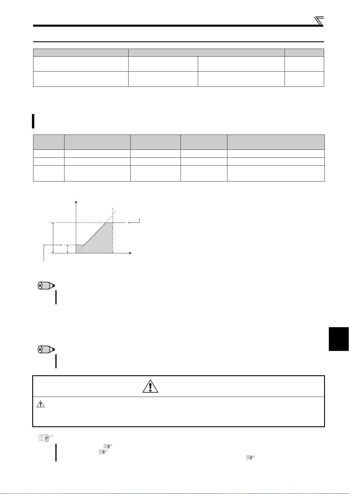
4.4 Limit the output frequency
Purpose Parameter that should be Set Refer to Page
Set upper limit and lower limit of
output frequency
Perform operation by avoiding
mechanical resonance points
4.4.1 Maximum/minimum frequency (Pr. 1, Pr. 2, Pr. 18)
Motor speed can be limited.
Clamp the upper and lower limits of the output frequency.
Maximum/minimum
frequency
Frequency jump Pr. 31 to Pr. 36
Limit the output frequency
Pr. 1, Pr. 2, Pr. 18
83
84
Parameter
Number
1 Maximum frequency
2 Minimum frequency
18 ∗
* The above parameters can be set when Pr. 160 Extended function display selection = "0". (Refer to page 162)
Output frequency
Pr. 1
Pr. 18
Clamped at the
minimum frequency
High speed maximum
frequency
(Hz)
Pr. 2
(4mA)
Name Initial Value Setting Range Description
120Hz 0 to 120Hz Upper limit of the output frequency.
0Hz 0 to 120Hz Lower limit of the output frequency.
120Hz 120 to 400Hz
Clamped at the
maximum frequency
(1) Set maximum frequency
Use Pr. 1 Maximum frequency to set the maximum frequency. If the
frequency of the frequency command entered is higher than the
setting, the output frequency is clamped at the maximum frequency.
To perform operation above 120Hz, set the upper limit of the output
Frequency setting
0
5, 10V
(20mA)
frequency to Pr. 18 High speed maximum frequency.
(When Pr. 18 is set, Pr. 1 automatically switches to the frequency of
Pr. 18. Also, when Pr. 1 is set, Pr. 18 is automatically changed to the
frequency set in Pr. 1.
REMARKS
When performing operation above 60Hz using the frequency setting analog signal, change Pr. 125 (Pr. 126) (frequency setting
gain).
Set when performing the operation at 120Hz
or more.
(2) Set minimum frequency
Use Pr. 2 Minimum frequency to set the minimum frequency.
If the set frequency is less than Pr. 2, the output frequency is clamped at Pr. 2 (will not fall below Pr. 2 ).
REMARKS
When Pr. 15 Jog frequency is equal to or less than Pr. 2, the Pr. 15 setting has precedence over the Pr. 2 setting.
When stall prevention is activated to decrease the output frequency, the output frequency may drop to Pr. 2 or below.
CAUTION
Note that when Pr. 2 is set to any value equal to or more than Pr. 13 Starting frequency, simply turning on the start
signal will run the motor at the preset frequency according to the set acceleration time even if the command
frequency is not input.
Parameters referred to
Pr. 13 Starting frequency Refer to page 98
Jog frequency Refer to page 91
Pr. 15
Pr. 125 Terminal 2 frequency setting gain frequency, Pr. 126 Terminal 4 frequency setting gain frequency Refer to page 153
4
PARAMETERS
83
Page 88
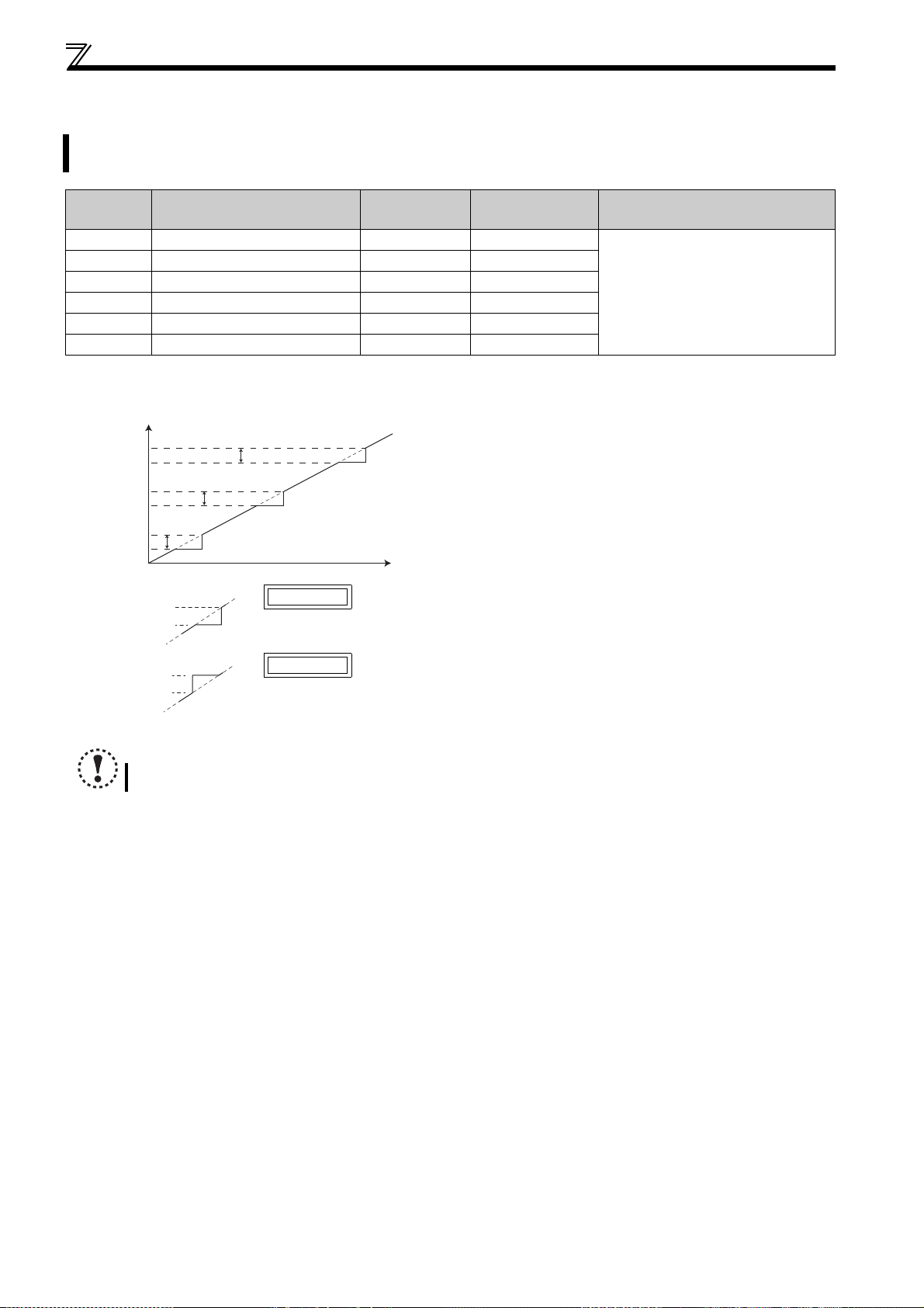
Limit the output frequency
P
P
P
P
4.4.2 Avoid mechanical resonance points (frequency jumps) (Pr. 31 to Pr. 36)
When it is desired to avoid resonance attributable to the natural frequency of a mechanical system, these parameters
allow resonant frequencies to be jumped.
Parameter
Number
31 Frequency jump 1A
32 Frequency jump 1B
33 Frequency jump 2A
34 Frequency jump 2B
35 Frequency jump 3A
36 Frequency jump 3B
The above parameters can be set when Pr. 160 Extended function display selection = "0". (Refer to page 162)
Name Initial Value Setting Range Description
9999 0 to 400Hz, 9999
9999 0 to 400Hz, 9999
9999 0 to 400Hz, 9999
9999 0 to 400Hz, 9999
9999 0 to 400Hz, 9999
9999 0 to 400Hz, 9999
Up to three areas may be set, with the jump frequencies set to
Pr. 36
Pr. 35
Pr. 34
Pr. 33
Set frequency (Hz)
Pr. 32
Pr. 31
r. 34: 35Hz
r. 33: 30Hz
Frequency jump
Example 1 To fix the frequency to 30Hz in the range of 30Hz to 35Hz, set 35Hz in Pr. 34
and 30Hz in Pr. 33.
either the top or bottom point of each area.
The value set to 1A, 2A or 3A is a jump point, and operation in
the jump zone is performed at these frequencies.
1A to 1B, 2A to 2B, 3A to 3B are
frequency jumps
9999: Function invalid
r. 33: 35Hz
r. 34: 30Hz
Example 2 To jump the frequency to 35Hz in the range of 30Hz to 35Hz, set 35Hz in Pr.
33 and 30Hz in Pr. 34.
NOTE
During acceleration/deceleration, the running frequency within the set area is valid.
84
Page 89

4.5 Set V/F pattern
V/F
Purpose Parameter that should be Set Refer to Page
Set motor ratings
Select a V/F pattern according to
applications.
4.5.1 Base frequency, voltage (Pr. 3, Pr. 19, Pr. 47)
Used to adjust the inverter outputs (voltage, frequency) to the motor rating.
Base frequency,
Base frequency voltage
Load pattern selection Pr. 14
Pr. 3, Pr. 19, Pr. 47
V/F
V/F
Set V/F pattern
85
87
Parameter
Number
3 Base frequency
19 ∗ Base frequency voltage
47 ∗
* The above parameters can be set when Pr. 160 Extended function display selection = "0". (Refer to page 162)
Second V/F (base
frequency)
Name Initial Value Setting Range Description
60Hz 0 to 400Hz Rated motor frequency (50Hz/60Hz)
0 to 1000V Base voltage
9999
9999
8888 95% of power supply voltage
9999 Same as power supply voltage
0 to 400Hz Base frequency when the RT signal is on
9999 Second V/F invalid
(1) Base frequency setting (Pr. 3)
When operating a standard motor, generally set the rated
frequency of the motor to Pr. 3 Base frequency. When running the
motor using commercial power supply-inverter switch-over
operation, set Pr. 3 to the same value as the power supply
frequency.
Pr. 19
Output voltage (V)
Output frequency
(Hz)
Pr. 3
Pr. 47
If the frequency given on the motor rating plate is "50Hz" only,
always set to "50Hz". Leaving the base frequency unchanged from
"60Hz" may make the voltage too low and the torque insufficient. It
may result in an inverter trip due to overload.
Special care must be taken when "1" (variable torque load) is set in
Pr. 14 Load pattern selection .
When using the Mitsubishi constant-torque motor, set Pr. 3 to
60Hz.
(2) Set two kinds of base frequencies (Pr. 47)
To change the base frequency when switching two types of motors with one inverter, use the Pr. 47 Second V/F (base
frequency).
4
Pr. 47 Second V/F (base frequency) is valid when the RT signal is on. Set "3" in any of Pr. 178 to Pr. 182 (input terminal function
selection) and assign the RT signal.
REMARKS
The RT signal acts as the second function selection signal and makes the other second functions valid. (Refer to page 116)
PARAMETERS
85
Page 90

Set V/F pattern
(3) Base frequency voltage setting (Pr. 19)
Use Pr. 19 Base frequency voltage to set the base voltage (e.g. rated motor voltage).
If the setting is less than the power supply voltage, the maximum output voltage of the inverter is as set in Pr. 19.
Pr. 19 can be utilized in the following cases.
(a) When regeneration is high (e.g. continuous regeneration)
During regeneration, the output voltage becomes higher than the reference and may cause an overcurrent trip
(E.OC) due to an increased motor current.
(b) When power supply voltage variation is large
When the power supply voltage exceeds the rated voltage of the motor, speed variation or motor overheat may be
caused by excessive torque or increased motor current.
NOTE
When General-purpose magnetic flux vector control is selected, Pr. 3, Pr. 47 and Pr. 19 are invalid and Pr. 83 and Pr. 84
are valid.
Note that Pr. 3 or Pr. 47 value is valid as inflection points of S-pattern when Pr. 29 Acceleration/deceleration pattern selection
= "1" (S-pattern acceleration/deceleration A).
Changing the terminal assignment using Pr. 178 to Pr. 182 (input terminal function selection) may affect the other
functions. Make setting after confirming the function of each terminal.
Parameters referred to
Pr. 14 Load pattern selection Refer to page 87
Pr. 29 Acceleration/deceleration pattern selection Refer to page 99
Pr. 83 Rated motor voltage, Pr. 84 Rated motor frequency
Pr. 178 to Pr. 182 (input terminal function selection)
General-purpose magnetic flux vector control Refer to page 75
Refer to page 113
Refer to page 105
86
Page 91

Set V/F pattern
V/F
V/F
4.5.2 Load pattern selection (Pr. 14)
Optimum output characteristic (V/F characteristic) for the application and load characteristics can be selected.
V/F
Parameter
Number
14 Load pattern selection
The above parameters can be set when Pr. 160 Extended function display selection = "0". (Refer to page 162)
Pr. 14 = 0
Name Initial Value Setting Range Description
0 For constant torque load
1 For variable torque load
0
2
3
(1) Constant-torque load application (setting "0", initial value)
At or less than the base frequency, the output voltage varies linearly with the output
100%
frequency.
Set this value when driving the load whose load torque is constant even if the speed
varies, e.g. conveyor, cart or roll drive.
Output voltage
Pr. 3 Base frequency
Output frequency (Hz)
POINT
If the load is a fan or pump, select for constant-torque load (setting "0") in any of the following cases.
When a blower of large inertia moment (J) is accelerated in a short time
For constant-torque load such as rotary pump or gear pump
When load torque increases at low speed, e.g. screw pump
For constant torque elevators
(at reverse rotation boost of 0%)
For constant torque elevators
(at forward rotation boost of 0%)
Pr. 14 = 1
100%
Output voltage
Output frequency (Hz)
(2) Variable-torque load application (setting "1")
At or less than the base frequency, the output voltage varies with the output frequency
in a square curve.
Set this value when driving the load whose load torque varies in proportion to the
square of the speed, e.g. fan or pump.
Pr. 3 Base frequency
4
PARAMETERS
87
Page 92
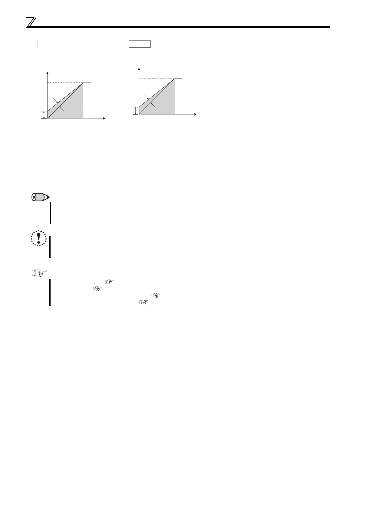
Set V/F pattern
Pr. 14 = 2
For vertical lift loads
At forward rotation boost...Pr. 0 (Pr. 46)
setting
At reverse rotation boost...0%
100%
Forward
rotation
Output voltage
Pr. 0
Pr. 46
Reverse
rotation
Base frequency
Output frequency (Hz)
REMARKS
When torque is continuously regenerated as vertical lift load, it is effective to set the rated voltage in Pr. 19 Base frequency voltage
to prevent trip due to current at regeneration.
When the RT signal is on, the other second functions are also valid.
Pr. 14 = 3
For vertical lift loads
At forward rotation boost...0%
At reverse rotation boost...
setting
100%
Reverse
rotation
Output voltage
Pr. 0
Pr. 46
Forward
rotation
Output frequency (Hz)
Pr. 0 (Pr. 46)
Base frequency
(3) Constant-torque load application
(setting "2, 3")
Set "2" when a vertical lift load is fixed as power
driving load at forward rotation and
regenerative load at reverse rotation.
Pr. 0 Torque boost is valid during forward rotation
and torque boost is automatically changed to
"0%" during reverse rotation. Pr. 46 Second
torque boost is valid when the RT signal turns
on.
Set "3" for an elevated load that is in the driving
mode during reverse rotation and in the
regenerative load mode during forward rotation
according to the load weight, e.g. counterweight
system.
For the RT signal, set "3" in any of Pr. 178 to Pr.
182 (input terminal function selection) to assign
the function.
NOTE
Load pattern selection does not function under General-purpose magnetic flux vector control.
Changing the terminal assignment using Pr. 178 to Pr. 182 (input terminal function selection) may affect the other
functions. Make setting after confirming the function of each terminal.
Parameters referred to
Pr. 0, Pr. 46 (Torque boost) Refer to page 73
Pr. 3 Base frequency Refer to page 85
Pr. 178 to Pr. 182 (input terminal function selection) Refer to page 113
General-purpose magnetic flux vector control Refer to page 75
88
Page 93

Frequency setting by external terminals
4.6 Frequency setting by external terminals
Purpose Parameter that should be Set Refer to Page
Make frequency setting by
combination of terminals
Multi-speed operation
Perform Jog operation Jog operation Pr. 15, Pr. 16
Infinitely variable speed setting by
terminals
Remote setting function Pr. 59
4.6.1 Operation by multi-speed operation (Pr. 4 to Pr. 6, Pr. 24 to Pr. 27, Pr. 232 to Pr. 239)
Can be used to change the preset speed in the parameter with the contact signals.
Any speed can be selected by merely turning on-off the contact signals (RH, RM, RL, REX signals).
Parameter
Number
4
5
6
Multi-speed setting (high
speed)
Multi-speed setting (middle
speed)
Multi-speed setting (low
speed)
24 ∗ Multi-speed setting (speed 4)
25 ∗ Multi-speed setting (speed 5)
26 ∗ Multi-speed setting (speed 6)
27 ∗ Multi-speed setting (speed 7)
232 ∗ Multi-speed setting (speed 8)
233 ∗ Multi-speed setting (speed 9)
234 ∗ Multi-speed setting (speed 10)
235 ∗ Multi-speed setting (speed 11)
236 ∗ Multi-speed setting (speed 12)
237 ∗ Multi-speed setting (speed 13)
238 ∗ Multi-speed setting (speed 14)
239 ∗ Multi-speed setting (speed 15)
The above parameters allow its setting to be changed during operation in any operation mode even if "0" (initial value) is set in Pr. 77 Parameter write selection.
* The above parameters can be set when Pr. 160 Extended function display selection = "0". (Refer to page 162)
Name Initial Value Setting Range Description
60Hz 0 to 400Hz Frequency when RH turns on
30Hz 0 to 400Hz Frequency when RM turns on
10Hz 0 to 400Hz Frequency when RL turns on
9999 0 to 400Hz, 9999
9999 0 to 400Hz, 9999
9999 0 to 400Hz, 9999
9999 0 to 400Hz, 9999
9999 0 to 400Hz, 9999
9999 0 to 400Hz, 9999
9999 0 to 400Hz, 9999
9999 0 to 400Hz, 9999
9999 0 to 400Hz, 9999
9999 0 to 400Hz, 9999
9999 0 to 400Hz, 9999
9999 0 to 400Hz, 9999
Pr. 4 to Pr. 6, Pr. 24 to Pr. 27,
Pr. 232 to Pr. 239
Frequency from 4 speed to 15 speed can
be set according to the combination of
the RH, RM, RL and REX signals.
9999: not selected
89
91
93
Speed 1
(High speed)
Speed 2
(Middle speed)
Speed 4
Speed 3
Output frequency (Hz)
ON ON ON ON
RH
RM
RL
(Low speed)
ON
REMARKS
In the initial setting, if two or three of multi-speed settings are simultaneously selected, priority is given to the set frequency of
the lower signal.
For example, when the RH and RM signals turn on, the RM signal (Pr. 5) has a higher priority.
The RH, RM, RL signals are assigned to the terminal RH, RM, RL in the initial setting. By setting "0 (RL)", "1 (RM)", "2 (RH)" in
any of Pr. 178 to Pr. 182 (input terminal function selection), you can assign the signals to other terminals.
Speed 5
ON ON
Speed 6
ON
ONONON
Speed 7
(1) 3-Speed setting (Pr. 4 to Pr. 6)
The inverter operates at frequencies set in Pr. 4 when RH signal is on,
Pr. 5 when RM signal is on and Pr. 6 when RL signal is on.
4
Time
PARAMETERS
89
Page 94

Frequency setting by external terminals
(2) Multi-speed setting for 4th speed or more (Pr. 24 to Pr. 27, Pr. 232 to Pr. 239)
Frequency from 4th speed to 15th speed can be set according to the combination of the RH, RM, RL and REX signals. Set the
running frequencies in Pr. 24 to Pr. 27, Pr. 232 to Pr. 239 (In the initial value setting, 4th speed to 15th speed are invalid).
For the terminal used for REX signal input, set "8" in any of Pr. 178 to Pr. 182 (input terminal function selection) to assign the
function.
Speed 10
Speed 11
Speed 9
Speed 8
Output frequency (Hz)
RH
RM
RL
REX
∗1 When "9999" is set in Pr. 232 Multi-speed setting (speed 8), operation is
ON ON ON ON
ONON ON ON ON ON ON ON
*1
performed at frequency set in Pr. 6 when RH, RM and RL are turned off and
REX is turned on.
Speed 12
Speed 13
Speed 14
ON ON ON ON
ON ON ON ON
Speed 15
Time
Forward rotation
Multi-speed
selection
Inverter
STF
REX
RH
RM
RL
SD
10
2
5
Multi-speed operation connection example
Frequency setting
potentiometer
REMARKS
The priorities of the frequency commands by the external signals are "Jog operation > multi-speed operation > terminal 4 analog
input > terminal 2 analog input".
(Refer to page 153 for the frequency command by analog input)
Valid in the external operation mode or PU/external combined operation mode (Pr. 79 = "3" or "4").
Multi-speed parameters can also be set in the PU or external operation mode.
Pr. 24 to Pr. 27 and Pr. 232 to Pr. 239 settings have no priority between them.
When Pr. 59 Remote function selection ≠ "0", multi-speed setting is invalid as RH, RM and RL signals are remote setting signals.
NOTE
Changing the terminal assignment using Pr. 178 to Pr. 182 (input terminal function selection) may affect the other
functions. Make setting after confirming the function of each terminal.
Parameters referred to
Pr. 15 Jog frequency Refer to page 91
Pr. 59 Remote function selection
Pr. 79 Operation mode selection
Pr. 178 to Pr. 182 (input terminal function selection) Refer to page 113
Refer to page 93
Refer to page 165
90
Page 95

Frequency setting by external terminals
P
4.6.2 Jog operation (Pr. 15, Pr. 16)
The frequency and acceleration/deceleration time for Jog operation can be set. Jog operation can be performed in either
of the external and the PU operation mode.
This operation can be used for conveyor positioning, test operation, etc.
Parameter
Number
15
16
These parameters are displayed as simple mode parameter only when the parameter unit (FR-PU04/FR-PU07) is connected. When the parameter unit is not
connected, the above parameters can be set by setting Pr. 160 Extended function display selection = "0". (Refer to page 162)
Name
Jog frequency
Jog acceleration/
deceleration time
Initial
Value
5Hz 0 to 400Hz Frequency for Jog operation.
0.5s 0 to 3600s
Setting Range Description
Acceleration/deceleration time for Jog operation. Acceleration/
deceleration time is the time taken to reach the frequency set in Pr. 20
Acceleration/deceleration reference frequency (initial value is 60Hz).
Acceleration/deceleration time can not be set separately.
(1) Jog operation from outside
When the JOG signal is on, a start and stop can be made by the start signal (STF, STR).
For the terminal used for Jog operation selection, set "5" in any of Pr.178 to Pr.182 (input terminal function selection) to assign
the function.
Output frequency (Hz)
Pr. 20
r. 15 Jog frequency
setting range
JOG signal
Forward rotation STF
Reverse rotation STR
Forward
rotation
Pr. 16
ON
ON
Reverse
rotation
ON
Time
Three-phase AC
power supply
Forward rotation
start
Reverse rotation
start
JOG signal
Connection diagram
for external Jog operation
Inverter
1
R/L
S/L2
T/L3
STF
STR
RH (JOG)*
SD
10
2
5
* When assigning the JOG signal to
the terminal RH
U
Motor
V
W
Operation Display
1. Screen at powering on
Confirm that the external operation mode is
selected. ([EXT] lit)
If not displayed, press to change to the
external (EXT) operation mode. If the
operation mode still does not change, set Pr.
79 to change to the external operation mode.
2. Turn on the JOG switch.
3. Turn the start switch (STF or STR) on.
The motor runs while the start switch (STF
or STR) is on.
The motor runs at 5Hz. (initial value of Pr.
15)
4. Turn the start switch (STF or STR) off.
REMARKS
When you want to change the running frequency, change Pr. 15 Jog frequency. (initial value "5Hz")
When you want to change the acceleration/deceleration time, change Pr. 16 Jog acceleration/deceleration time. (initial value "0.5s")
The acceleration time and deceleration time cannot be set separately for Jog operation.
Forward
rotation
ON
Forward
rotation
OFF
ON
JOG
Reverse
rotation
Reverse
rotation
4
Rotates while ON
Stop
PARAMETERS
91
Page 96
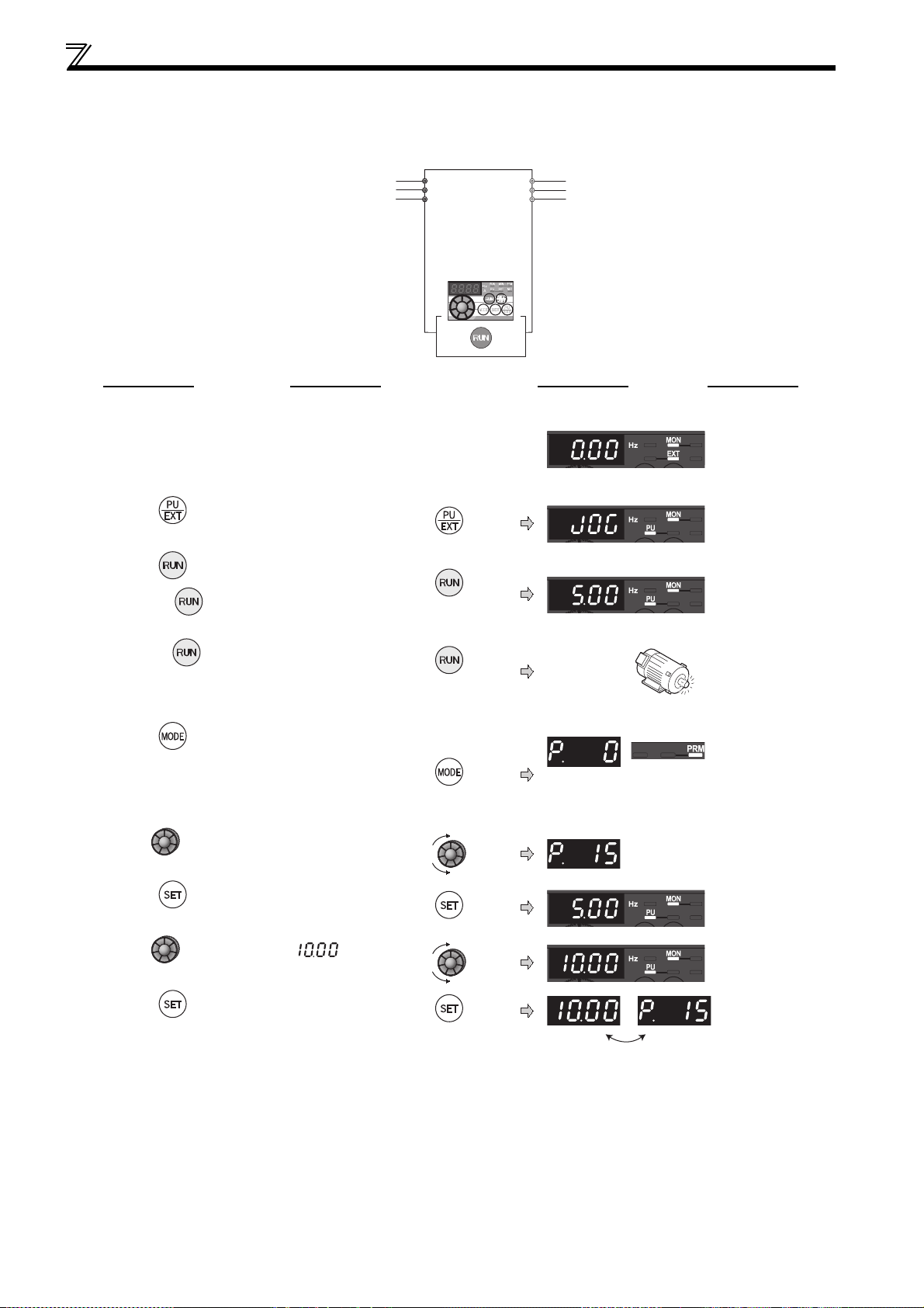
Frequency setting by external terminals
(2) Jog operation from PU
Selects Jog operation mode from the operation panel and PU (FR-PU04/FR-PU07). Operation is performed only while the
start button is pressed.
Inverter
Three-phase AC
power supply
R/L1
S/L2
T/L3
Operation panel
U
V
W
Motor
Operation Display
1. Confirmation of the RUN indication and
operation mode indication
The monitor mode should have been
selected.
The inverter should be at a stop.
2. Press to choose the PU Jog operation
mode.
3. Press .
While is pressed, the motor rotates.
The motor runs at 5Hz. (Pr. 15 initial value)
4. Release
[When changing the frequency of PU Jog operation]
5. Press to choose the parameter setting
mode.
6. Turn until Pr. 15 Jog frequency appears.
7. Press to show the present set value.
(5Hz)
8. Turn to set the value to " ".
(10Hz)
Press
Stop
Release
PRM indication is lit.
(The parameter number read previously
appears.)
9. Press to set.
10.Perform the operations in steps 1 to 4.
The motor rotates at 10Hz.
92
Flicker...Parameter setting complete!!
Page 97
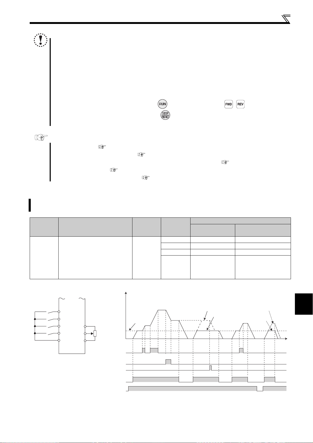
Frequency setting by external terminals
NOTE
When Pr. 29 Acceleration/deceleration pattern selection = "1" (S-pattern acceleration/deceleration A), the acceleration/
deceleration time is the period of time required to reach Pr. 3 Base frequency.
The Pr. 15 setting should be equal to or higher than the Pr. 13 Starting frequency.
The JOG signal can be assigned to the input terminal using any of Pr. 178 to Pr. 182 (input terminal function selection).
When terminal assignment is changed, the other functions may be affected. Please make setting after confirming the
function of each terminal.
During Jog operation, the second acceleration/deceleration via the RT signal cannot be selected. (The other second
functions are valid. (Refer to page 227))
When Pr. 79 Operation mode selection = "4", pressing of the operation panel and
(FR-PU04/FR-PU07) starts the inverter and pressing stops the inverter.
This function is invalid when Pr. 79 = "3".
/ of the parameter unit
Parameters referred to
Pr. 13 Starting frequency Refer to page 98
Pr. 29 Acceleration/deceleration pattern selection Refer to page 99
Pr. 20 Acceleration/deceleration reference frequency, Pr. 21 Acceleration/deceleration time increments Refer to page 96
Pr. 79 Operation mode selection Refer to page 165
Pr. 178 to Pr. 182 (input terminal function selection) Refer to page 113
4.6.3 Remote setting function (Pr. 59)
Even if the operation panel is located away from the enclosure, you can use contact signals to perform continuous
variable-speed operation, without using analog signals.
Parameter
Number
59
The above parameter can be set when Pr. 160 Extended function display selection = "0". (Refer to page 156)
Remote function selection
Name Initial Value
0
Setting
Range
0 Multi-speed setting —
1 Remote setting With
2 Remote setting Not used
3 Remote setting
RH, RM, RL signal
function
Description
Frequency setting
storage function
Not used
(Turning STF/STR off
clears remotely-set
frequency.)
Forward rotation
Acceleration
Deceleration
Clear
Connection diagram
for remote setting
STF
RH
RM
RL
SD
Inverter
10
4
ON
When Pr. 59 = 1
Time
PARAMETERS
ON
93
When Pr. 59 = 1, 2
When Pr. 59 = 3
*
2
5
Acceleration
Deceleration
Forward rotation
Power supply
Output frequency (Hz)
0Hz
0
ON
(RH)
(RM)
Clear (RL)
(STF)
* External running frequency (other than multi-speed) or PU running frequency
ON
ON
ON
ON
ON
ON ON
When Pr. 59 = 2, 3
ON
Page 98
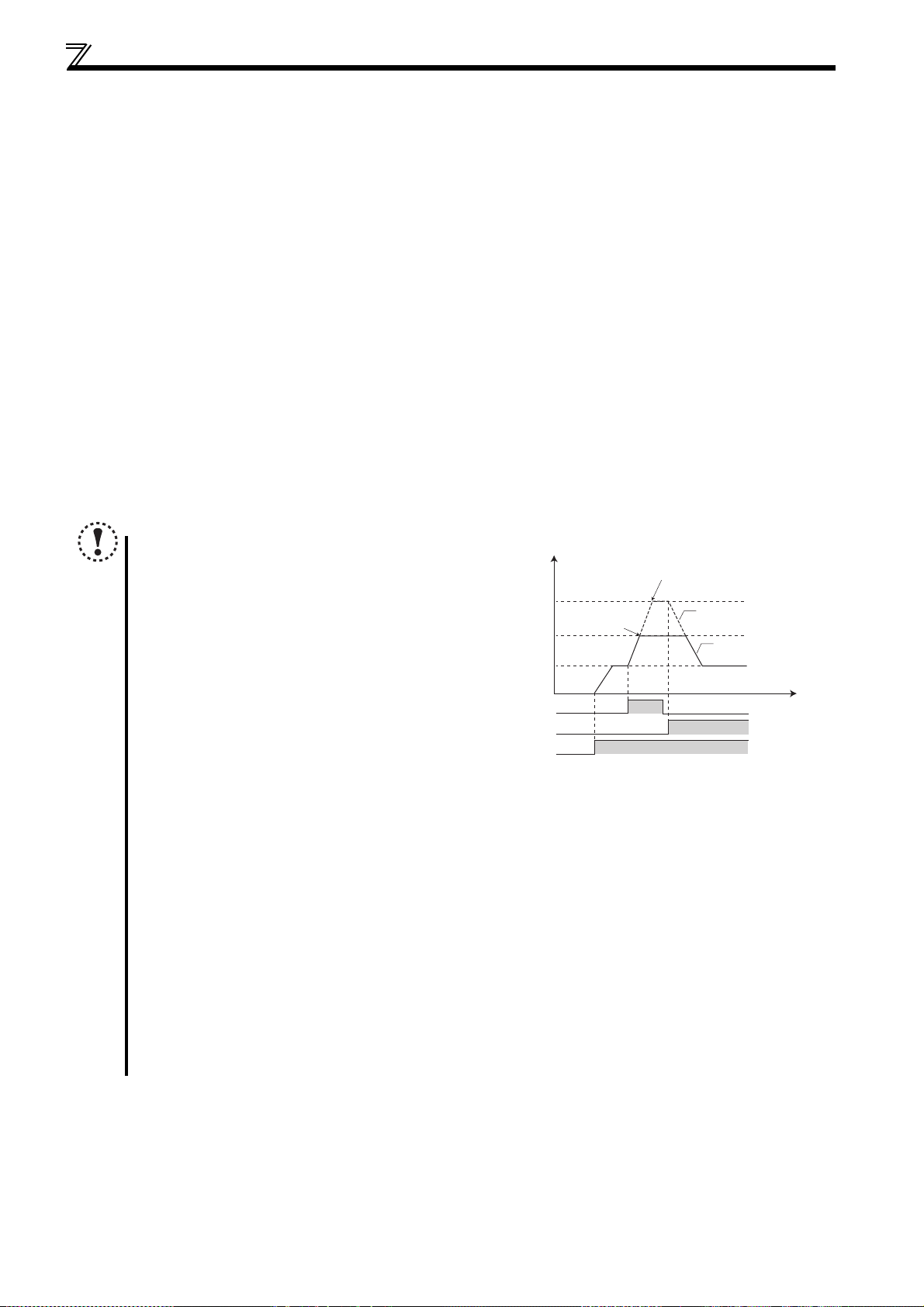
Frequency setting by external terminals
(1) Remote setting function
Use Pr. 59 to select whether the remote setting function is used or not and whether the frequency setting storage function
in the remote setting mode is used or not.
When Pr. 59 is set to any of "1 to 3" (remote setting function valid), the functions of the RH, RM and RL signals are
changed to acceleration (RH), deceleration (RM) and clear (RL).
When using the remote setting function, following frequencies can be compensated to the frequency set by RH and RM
operation according to the operation mode.
During external operation (including
During external operation and PU combined operation (
During PU operation ...............................................................................PU frequency command
(2) Frequency setting storage
The frequency setting storage function stores the remotely-set frequency (frequency set by RH/RM operation) into the
memory (EEPROM). When power is switched off once, then on, operation is resumed with that output frequency value.
(Pr. 59 = 1)
<Frequency setting storage conditions>
Frequency at the point when the start signal (STF or STR) turns off
Remotely-set frequency is stored every minute after turning OFF (ON) the RH (acceleration) and RM(deceleration)
signals together. (The frequency is overwritten if the latest frequency is different from the previous frequency when
comparing the two. The state of the RH signal does not affect writing.)
Pr. 79
= "4") ...................................external frequency command other than multi-speed
settings
Pr. 79
= "3") .....PU frequency command or terminal 4 input
NOTE
The range of frequency changeable by RH
(acceleration) and RM (deceleration) is 0 to
maximum frequency (Pr. 1 or Pr. 18 setting).
Note that the maximum value of set frequency
is (main speed + maximum frequency).
Main speed setting
Acceleration (RH)
Deceleration (RM)
Forward rotation (STF)
When the acceleration or deceleration signal switches ON, acceleration/deceleration time is as set in Pr. 44 Second
acceleration/deceleration time and Pr. 45 Second deceleration time. Note that when the time set in Pr. 7 or Pr. 8 is longer than
the time set in Pr. 44 or Pr. 45, the acceleration/deceleration time is as set in Pr. 7 or Pr. 8. (when RT signal is OFF)
When the RT signal is on, acceleration/deceleration is made in the time set in Pr. 44 and Pr. 45, regardless of the Pr. 7
or Pr. 8 setting.
Even if the start signal (STF or STR) is off, turning on the acceleration (RH) or deceleration (RM) signal varies the
preset frequency. (When Pr. 59 = "1" or "2")
When switching the start signal from ON to OFF, or changing frequency by the RH or RM signal frequently, set the
frequency setting value storage function (write to EEPROM) invalid (Pr. 59 = "2, 3"). If set valid (Pr. 59 = "1"), frequency
is written to EEPROM frequently, this will shorten the life of the EEPROM.
The RH, RM, RL signals can be assigned to the input terminal using any Pr. 178 to Pr. 182 (input terminal function
selection). When terminal assignment is changed, the other functions may be affected. Please make setting after
confirming the function of each terminal.
Also available for the network operation mode.
(Hz)
Output frequency is
clamped at Pr. 1
Pr. 1
0Hz
ON
The set frequency is clamped
at (main speed + Pr. 1)
Set frequency
Output frequency
Time
ON
ON
94
Page 99
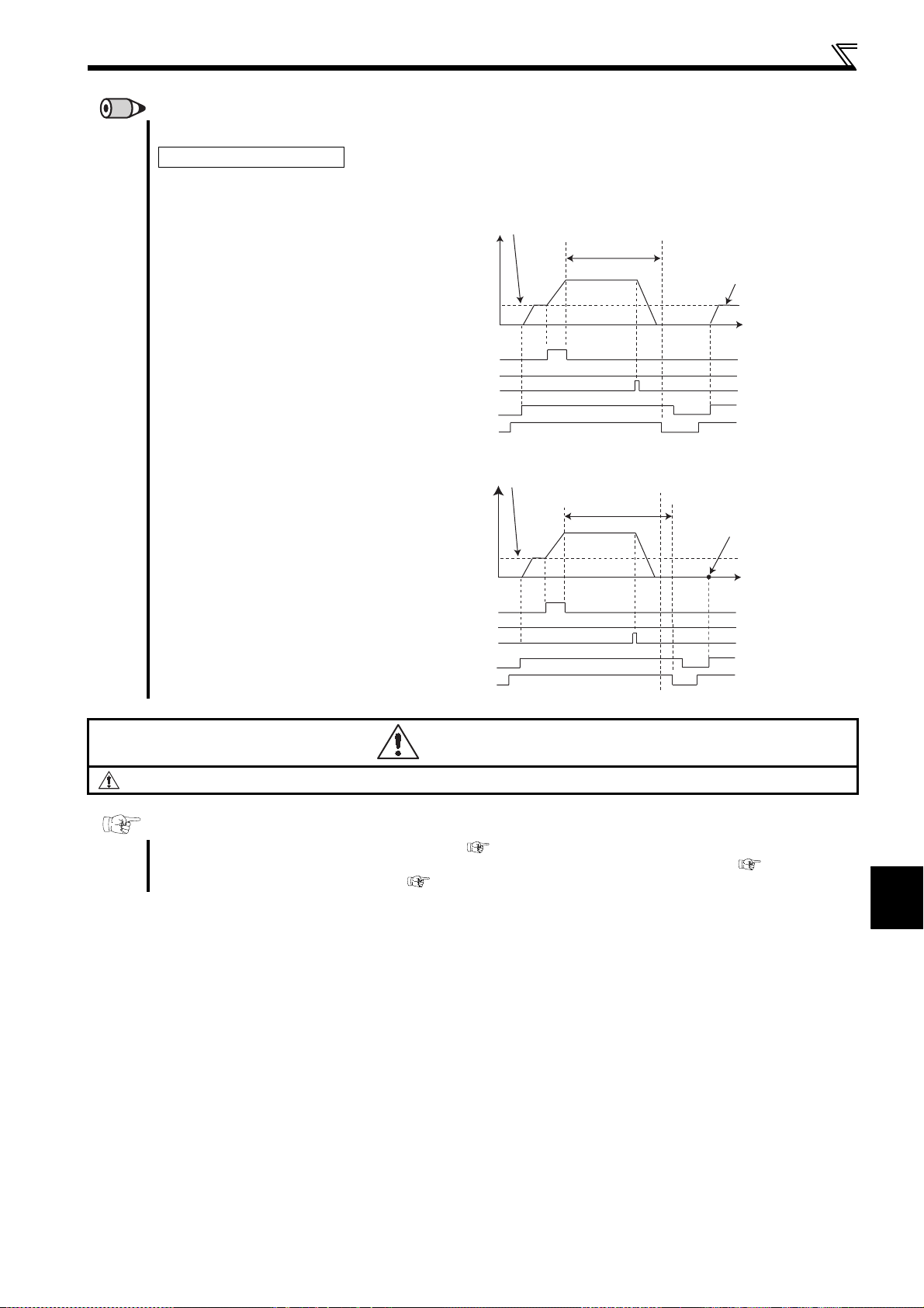
Frequency setting by external terminals
REMARKS
During Jog operation or PID control operation, the remote setting function is invalid.
Setting frequency is "0"
Even when the remotely-set
frequency is cleared by turning on
the RL (clear) signal after turn off
(on) of both the RH and RM
signals, the inverter operates at
the remotely-set frequency stored
in the last operation if power is
reapplied before one minute has
elapsed since turn off (on) of both
the RH and RM signals
Acceleration (RH)
Deceleration (RM)
Forward rotation (STF)
Power supply
When the remotely-set frequency
is cleared by turning on the RL
(clear) signal after turn off (on) of
both the RH and RM signals, the
inverter operates at the frequency
in the remotely-set frequency
cleared state if power is reapplied
after one minute has elapsed
since turn off (on) of both the RH
and RM signals.
Acceleration (RH)
Deceleration (RM)
Forward rotation (STF)
Power supply
Clear (RL)
Clear (RL)
(Hz)
Remotely-set frequency stored last time
Within 1 minute
Output frequency
OFF
Remotely-set frequency
(Hz)
stored last time
Output frequency
OFF
ON
ON
ON
ON
More than 1 minute
ON
ON
ON
ON
1 minute
Remotely-set frequency
stored last time
Time
ON
ON
Operation is performed
at the set frequency 0Hz.
Time
ON
ON
CAUTION
When selecting this function, re-set the maximum frequency according to the machine.
Parameters referred to
Pr. 1 Maximum frequency, Pr. 18 High speed maximum frequency Refer to page 83
Pr. 7 Acceleration time, Pr. 8 Deceleration time, Pr. 44 Second acceleration/deceleration time, Pr. 45 Second deceleration time Refer to page 96
Pr. 178 to Pr. 182 (input terminal function selection) Refer to page 113
4
PARAMETERS
95
Page 100

Setting of acceleration/deceleration time and acceleration/ deceleration pattern
4.7 Setting of acceleration/deceleration time and acceleration/ deceleration pattern
Purpose Parameter that should be Set Refer to Page
Motor acceleration/deceleration
time setting
Starting frequency
Set acceleration/deceleration
pattern suitable for application
4.7.1 Setting of the acceleration and deceleration time
(Pr. 7, Pr. 8, Pr. 20, Pr. 44, Pr. 45)
Used to set motor acceleration/deceleration time.
Set a larger value for a slower speed increase/decrease or a smaller value for a faster speed increase/decrease.
For the acceleration time at automatic restart after instantaneous power failure, refer to Pr. 611 Acceleration time at a
restart (page 136).
Acceleration/deceleration
times
Starting frequency and
start-time hold
Acceleration/deceleration
pattern
Pr. 7, Pr. 8, Pr. 20, Pr. 44, Pr. 45
Pr. 13, Pr. 571
Pr. 29
96
98
99
Parameter
Number
7 Acceleration time
8 Deceleration time
Name Initial Value
FR-D720-165 or less
FR-D740-080 or less
FR-D720S-008 to 100
FR-D720-238 or more
FR-D740-120 or more
FR-D720-165 or less
FR-D740-080 or less
FR-D720S-008 to 100
FR-D720-238 or more
FR-D740-120 or more
5s
10s
5s
10s
Acceleration/
20 ∗1
deceleration
60Hz 1 to 400Hz
reference frequency
FR-D720-165 or less
44 ∗1
45 ∗1
∗1 The above parameters can be set when Pr. 160 Extended function display selection = "0". (Refer to page 162)
Second acceleration/
deceleration time
Second deceleration
time
FR-D740-080 or less
FR-D720S-008 to 100
FR-D720-238 or more
FR-D740-120 or more
9999
5s
10s
Setting
Range
0 to 3600s Motor acceleration time.
0 to 3600s Motor deceleration time.
Frequency that will be the basis of
acceleration/deceleration time.
As acceleration/deceleration time, set the
frequency change time from stop to Pr. 20.
0 to 3600s
0 to 3600s Deceleration time when the RT signal is on.
9999 Acceleration time = deceleration time
Acceleration/deceleration time when the RT
signal is on.
Description
(1) Acceleration time setting (Pr. 7, Pr. 20)
Pr. 20
(60Hz)
(Hz)
Output
frequency
Acceleration time
Pr. 7, Pr. 44
Deceleration time
Running
frequency
Time
Pr. 8, Pr. 45
Example)When Pr. 20 = 60Hz (initial value), Pr. 13 = 0.5Hz, and acceleration can be
made up to the maximum operating frequency of 50Hz in 10s
Use Pr. 7 Acceleration time to set the acceleration time required to reach Pr. 20
Acceleration/deceleration reference frequency from 0Hz.
Set the acceleration time according to the following formula.
Acceleration
time setting
=
Pr. 20
Maximum operating
frequency - Pr. 13
96
Acceleration time from stop to maximum
×
operating frequency
Pr. 7 =
60Hz
50Hz - 0.5Hz
×
10s 12.1s
 Loading...