

Page 1

INVERTER
FR-D700
INSTRUCTION MANUAL (BASIC)
FR-D720-0.1K to 15K
FR-D740-0.4K to 15K
FR-D720S-0.1K to 2.2K
FR-D710W-0.1K to 0.75K
Thank you for choosing this Mitsubishi Inverter.
This Instruction Manual (B asic) provides handling info rmation and precautions for use of the equipment.
Please forward this Instru ction Manual (Basic) to the e nd user.
CONTENTS
OUTLINE ...................................................................................1
1
INSTALLATION AND WIRING ...................................................5
2
PRECAUTIONS FOR USE OF THE INVERTER.........................18
3
FAILSAFE OF THE SYSTEM WHICH USES THE INVERTER ...20
4
DRIVE THE MOTOR.................................................................21
5
ENERGY SAVING OPERATION FOR FANS AND PUMPS ........29
6
PARAMETERS .........................................................................30
7
TROUBLESHOOTING ..............................................................34
8
PRECAUTIONS FOR MAINTENANCE AND INSPECTION ........38
9
SPECIFICATIONS....................................................................40
10
To obtain the Instruction Manual (Applied) and the
Safety stop function instruction manual
Contact where you purchased the inverter, your Mitsubishi sales
representative, or the nearest Mitsubishi FA Center for the following
manuals:
y Instruction Manual (Applied) [IB(NA)-0600366ENG]
y Safety stop function instruction manual [BCN-A211508-000]
These manuals are required if you are going to utilize functions and
performance.
The PDF version of this manual is also available for download at
"MELFANS Web," the Mitsubishi Electric FA network service on the
world wide web (URL: http://www.MitsubishiElectric.co.jp/melfansweb)
700
1
2
3
4
5
6
7
8
9
10
Page 2
This Instruction Manual (Basic) provides handling information and precautions for use of the equipment.
Please forward this Instruction Manual (Basic) to the end user.
This section is specifically about safety matters
Do not attempt to install, operate, maintain or ins pect the
inverter until you have read through the Instruction Manual
(Basic) and appended documents carefully and can use the
equipment correctly. Do not use this product until you have a
full knowledge of the equipment, safety information and
instructions.
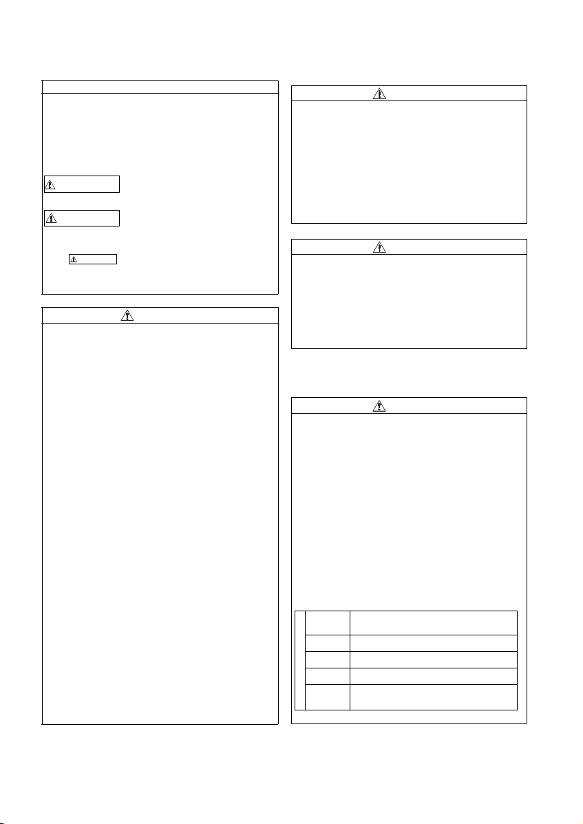
In this Instruction Manual (Basic), the safety instruction levels
are classified into "WARNING" an d "CAUTION".
WARNIN G
CAUTION
CAUTION
The level may even lead to a serious
consequence according to conditions. Both instruction levels
must be followed because these are important to personal
safety.
Incorrect handling may cause
hazardous conditions, resulting in
death or severe injur y.
Incorrect handling may cause
hazardous conditions, resulting in
medium or slight injury, or may cause
only material damage.
1. Electric Shock Prevention
WARNING
z While power is ON or when the inverter is running, do not
open the front cover. Otherwise you may get an electric
shock.
z Do not run the invert er with the front cover o r wiring cover
removed. Otherwise you may access the exposed highvoltage terminals or the ch arging part of the circuitry and
get an electric shock.
z Even if power is OFF, do not remove the front cover except
for wiring or periodic inspection. You may accidentally
touch the charged inverter circuits and get an electric
shock.
z Before wiring or insp ection, power must be sw itched OFF.
To confirm that, LED indication of the operation panel must
be checked. (It must b e OFF.) Any person who is involved in
wiring or inspect ion shall wait for at least 10 minutes after
the power supply has been switched OFF and check that
there are no residual voltage using a test er or the like. The
capacitor is charged with high voltage for some time after
power OFF, and it is dangerous.
This inverter must be earthed (grounded). Earthing
z
(grounding) must conform to the requirements of national and
local safety regu lations and elect rical code (NEC secti on 250,
IEC 536 class 1 and other applicable standards).
A neutral-point ear thed (grounded) power su pply for 400V
class inverter in compliance with EN standard must be u sed.
z Any person who is involved in wiring or inspection of this
equipment shall be f ully competent to do the wor k.
z The inverter must be installed before wiring. Otherwise you
may get an electric shock or be injured.
z Setting dial and key operations must be performed with dry
hands to prevent an electr ic shock. Otherwise you may g et
an electric shock.
z Do not subject the ca bles to scratches, exc essive stress,
heavy loads or pinching. O therwise you may get an electric
shock.
z Do not change the cooling fan while power is ON. It is
dangerous to change the cooling fan while power is ON.
z Do not touch the printed circuit boa rd or handle the cab les
with wet hands. Otherwise you may get an electric shock.
z When measuring th e main circuit capacitor ca pacity, the DC
voltage is applied to the motor for 1s at powering OFF.
Never touch the motor terminal, etc. right after powering
OFF to prevent an e lectric shock.
2. Fire Prevention
z Inverter must be installed on a nonflammable wall without
holes (so that nobody touches the inverter heatsink on the
rear side, etc.). Mounting it to or near flammable material
can cause a fire.
z If the inverter has become faulty, the inverter pow er must
be switched OFF. A continuous flow of large current could
cause a fire.
z
When using a brake resistor, a sequence that will turn OFF
power when a fault signal is outp ut must be configured.
Otherwise the brake resistor may overheat due to damage of
the brake transistor and possibly cause a fire.
z Do not connect a resistor di rectly to the DC terminal s P/+
and N/-. Doing so could cause a fire.
CAUTION
3.Injury Prevention
z T he voltage applied to each termi nal must be the ones
specified in the Instru ction Manual. Otherwise bu rst,
damage, etc. may occu r.
z T he cables must be connected to t he correct terminals.
Otherwise burst, damage, etc. may occur.
z Po larity must be correct. Otherwise b urst, damage, etc.
may occur.
z W hile power is ON or for some time after power-OFF, do not
touch the inverter sin ce the inverter will be extremely hot.
Doing so can cause burns.
4. Additional Instructions
Also the following points must be noted to prevent an
accidental failure, injury, electric shock, etc.
CAUTION
(1) Transportation and Mounting
CAUTION
z The product must be transported in correct method that
corresponds to the weight. Failure to do so may lead to
injuries.
z Do not stack the boxes containing inverters higher than the
number recommended.
z The product must be installed to the position where
withstands the weight of the product according to the
information in the In struction Manual.
z Do not install or operate the inverter if it is d amaged or has
parts missing.
z W hen carrying the inverter, do not hold it by the front cover
or setting dial; it may fall off or fail.
z Do not stand or rest heavy objects on the product.
z The inverter mounting orientation must be correct.
z Foreign conductive objects must be prevented from
entering the inverter. That includes screws and metal
fragments or other flam mable substance such as oil.
z As the inverter is a precision instrument, do not drop or
subject it to impact.
z The inverter must be used under the following
environment: Other wise the inverter may be damaged.
Surrounding
air
temperature
Ambient
humidity
Storage
temperature
Atmosphere
Environment
Altitude/
vibration
∗1 Temperature applicable for a short t ime, e.g. in transit.
-10°C to +50°C (non -freezing)
90%RH or less (non-condensing)
-20°C to +65°C *1
Indoors (free from corrosive gas, flammable gas,
oil mist, dust and di rt)
Maximum 1,000m above sea level.
2
or less at 10 to 55Hz (directions of X, Y, Z
5.9m/s
axes)
A-1
Page 3
(2) Wiring
z Do not install a power factor correction capacitor or surge
suppressor/capacitor type filter on the inverter output side.
These devices on the inverter output side may be
overheated or burn out.
z The connection orientation of the output cables U, V, W to
the motor affects the rotation direction of the motor.
CAUTION
(3) Trial run
z Be fore starting operation, each parameter must be
confirmed and adjuste d. A failure to do so may cause som e
machines to make unexpected motions .
CAUTION
(4) Usage
z An y person must stay away from the equ ipment when the
retry function is set as it will restart suddenly after trip.
z
Since pressing key may not stop output depending on
the function setting status, separate circuit and switch that
make an eme rgency stop (po wer OFF, mechanical bra ke
operation for emergency stop, etc.) must be provided.
z OFF status of the start signal must be confirmed before
resetting the inver ter fault. Resetting in verter alarm with the
start signal ON restarts the motor suddenly.
z The inverter must be used for three-phase induction
motors.
Connection of any other electrical equipment to the inverter
output may damage the equipment.
z Do not modify the equipment.
Do not perform parts removal which is not instructed in this
z
manual. Doi ng so may lead to fault or damage of the pr oduct.
z The electronic thermal relay function does not guarantee
protection of the motor from overheating. It is
recommended to install bo th an external thermal a nd PTC
thermistor for overh eat protection.
z Do not use a magnetic contactor on the inverter input for
frequent starting/stopping of the inverter. Otherwise, the
life of the inverter decreases.
z The effect of electromagnetic interference must be reduced
by using an EMC filter or by other means. Otherwise
nearby electronic equipment may be affected.
z Appr opriate measures must be taken to suppress
harmonics. Otherwise power supply harmonics from the
inverter may heat/da mage the power factor correction
capacitor and generator.
z W hen driving a 400V class motor by the inverter, the motor
must be an insulation-enha nced motor or measures mus t
be taken to suppress surge voltage. Surge voltage
attributable to the wirin g constants may occur at the mot or
terminals, deteriorating the insulation of the motor.
When parameter clear or all parameter clear is performed, the
z
required parameters must be set again before starting
operations because all parameters return to the initial value.
z T he inverter can be easi ly set for high-speed op eration.
Before changing its setting, the performances of the motor
and machine must be f ully examined.
z Stop status cannot be hold by the inverter's brake function.
In addition to the inverter's brake function, a holding device
must be installed to ensu re safety.
z Be fore running an inverter which had been stored for a
long period, inspection and test operation must be
performed.
z Static electricity in your body must be discharged before
you touch the product. Otherwise the product may be
damaged.
z If you are installing the inverter t o drive a three-phase
device while you are contracted for lighting and power
service, consult your electric power supplier.
WARNING
CAUTION
(5) Emergency stop
CAUTION
z A sa fety backup such as an emer gency brake must be
provided to prevent hazardous condition to the machine
and equipment in case of inverter failure.
z When the breaker on the inverter input side trips, the wiring
must be checked for fault (sho rt circuit), and internal parts
of the inverter for a damage, etc. The cause of the trip must
be identified and removed before turning ON the power of
the breaker.
z When any protective function is activated, appropriate
corrective action must be taken, and the inverter must be
reset before resuming operation.
(6) Maintenance, inspection and parts replacement
CAUTION
z Do not c arry out a megger (insulation resistance) test on
the control circuit of the inverter. It will cause a failure .
(7) Disposal
CAUTION
z The inverter must be treated as industrial waste.
General instruction
Many of the diagrams and drawings in this Instruction Manual
(Basic) show the inverter without a cover or partially ope n for
explanation. Never operate the inverter in this manner. The
cover must be always rein stalled and the instruction in this
Instruction Manual (Basic) must be followed when operating
the inverter.
<Abbreviation>
y PU: Operation panel and parameter unit (FR-PU04/FR-
PU07)
y Inverter: Mitsubishi inver ter FR-D700 series
y FR-D700: Mitsubishi inverter FR-D700 series
y Pr.: Parameter number (Number assigned to function)
y PU operation: Operation using the PU (operation panel/FR-
PU04/FR-PU07)
y External operation: Operation using the control circuit
signals
y Combined operation: Operation using both the PU
(operation panel/FR-PU04/FR-PU07) and External operation
y Standard motor : SF-JR
y Constant torque motor: SF-HRCA
<Trademark>
y Company and product names herein are the trademarks
and registered tradem arks of their respect ive owners.
<Mark>
REMARKS:Additional helpful contents and relations
with other functions are stated.
Note
: Contents requiring caution or cases when
set functions are not activated are stated.
POINT
: Useful contents and points are stated.
<Related document>
Refer to the Instruction Manual (Applied) for further
information on the following points.
y Removal and reinstallation of th e cover
y Connection of stand-alone option unit
y EMC and leakage curr ents
y Detailed explanation on parameters
y Troubleshooting
y Check first when you have a trouble
y Inspection items (life diagnosis, cooling fan replacement)
y Measurement of main circu it voltages, currents and powers
y For customers who are re placing the conventional mod el
with this inverter
A-2
Page 4
1 OUTLINE
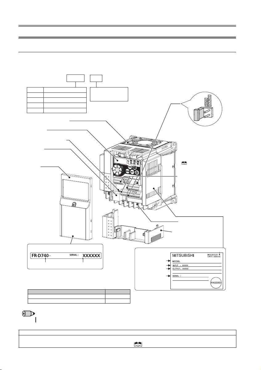
1.1 Product checking and parts identification
Unpack the inverter and check the capacity plate on the front cover and the rating plate on the inverter side face to ensure that
the product agrees with your order and the inverter is intact.
zInverter model
--
FR
D740 1.5
K
Symbol Voltage class
Three-phase 200V class
D720
Three-phase 400V class
D740
Single-phase 200V class
D720S
Single-phase 100V class
D710W
Cooling fan
Operation panel
(Refer to page 2)
Voltage/current input switch
(Refer to page 8)
PU connector
(Refer to page 8)
Front cover
Refer to the Instru ction
Manual (Applied) for
installation/removal.
The cooling f an is removable .
Represents the
inverter capacity [kW]
Capacity plate
1.5K
Inverter model
• Accessory
· Fan cover fixing screws (M3 × 35mm)
These screws are necessary for compliance with the
EU Directive. (
Serial number
Refer to page 43
Capacity Quantity
1.5K to 3.7K 1
5.5K to 15K 2
)
Rating plate
Inverter model
Input rating
Output rating
Serial number
Control logic switchover jumper
connector
The jumper connector is in the sink
logic (SINK) when shipped from the
factory. Move the jumper connector
to change to the source logic
(SOURCE). Always fit the jumper
connector to the either position.
( Refer to the Inst ruction Manual
(Applied))
Control circuit terminal block
(Refer to page 9)
Main circuit terminal block
(Refer to p age 9)
Combed shaped wiring cover
Refer to the Instruction Manual
(Applied) for installation /removal.
Production year and month
FR-D740-1.5K
REMARKS
·
For how to find the SERIA L number, refer to page 46.
Harmonic suppression guideline (when inverters are used in Japan)
All models of general -purpose inverters used by specific consumers are covered by "Harmonic Su ppression Guidelines for Con sumers
Who Receive High Voltage or Special High Voltage". (For fur ther details, refer to Chapter 3 of the Instruction Manual (Applied).)
1
Page 5
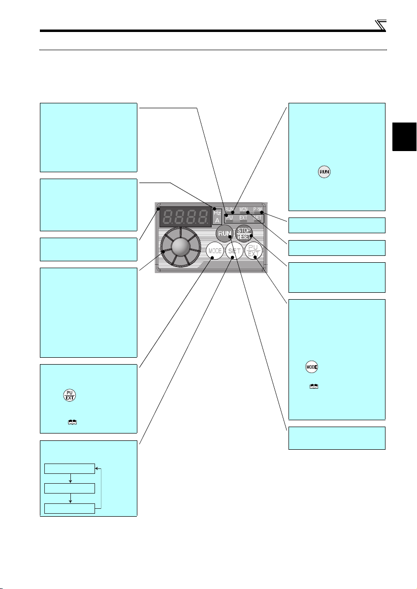
1.2 Operation panel
1.2.1 Names and functions of the operation panel
The operation panel cannot be removed from the inverter.
Operation panel
Operation mode indicator
PU: Lit to indicate P U operation mode.
EXT: Lit to indicate Extern al operation mode.
(Lit at power-ON at initial setting.)
NET: Lit to indicate Network operation mode.
PU, EXT: Lit to indicate External/PU
combined operation mode 1, 2.
These turn OFF whe n command source is
not on oper ation panel.
Unit indicator
Hz: Lit to indicate frequency.
(Flickers when the set frequency
monitor is displayed.)
A: Lit to indicate c urrent.
(Both "Hz" and "A" turn OFF when other
than the above is displayed.)
Monitor (4-digit LED)
Shows th e frequency, paramet er number,
etc.
Setting dial
(Setting dial: Mitsubishi inverter dial)
The setting dial is used to change the
frequency and parameter settings.
Press the setting dial to perform the
following operations:
y To display a set frequency in the
monitor mode
y To display the present setti ng during
calibration
y To display a fault history number in the
faults history mode
Mode switch over
Used to switch among different setting
modes.
Pressing simultaneously changes
the operation mode.
Pressing for a while (2s) can lock
operation. (
Manual (Applied))
Determination of each setting
If pressed during operation, monitor
changes as below:
Running frequency
Refer to the Instru ction
Operating status indicator
Lit or flicker during inverter operation.
* Lit: When the forward rotation operation
is being performed.
Slow flickering (1.4s cycle):
When the reverse rotation operation
is being performed.
Fast flickering (0.2s cycle):
yWhen was pressed or the start
command was given, but the
operation cannot be made.
yWhen the frequency command is less
than the starting frequency.
yWhen the MRS signal is input.
Parameter setting mode indicator
Lit to indicate paramete r setting mode.
Monitor indicator
Lit to indicate monitoring mode.
STOP operation
Used to stop operation commands.
Used to reset a fault when the protective
function (fault) is activated.
Operation mode switchover
Used to switch between the PU and
External operation modes.
To use the External operation mode
(operati on using a separat ely connecte d
frequency setting potentiometer and start
signal), press this key to lig ht up the EXT
indicator.
(Press simultaneously (0.5s), or
change
Pr. 79
mode .)
Manual (Applied))
PU: PU operation mode
EXT: External operation mode
Cancels PU stop also.
Start command
The rotation direction can be selected by
setting Pr. 40.
setting to change to c ombined
( Refer to the Instruction
∗
1
Output current
Output voltage
2
Page 6
Operation panel
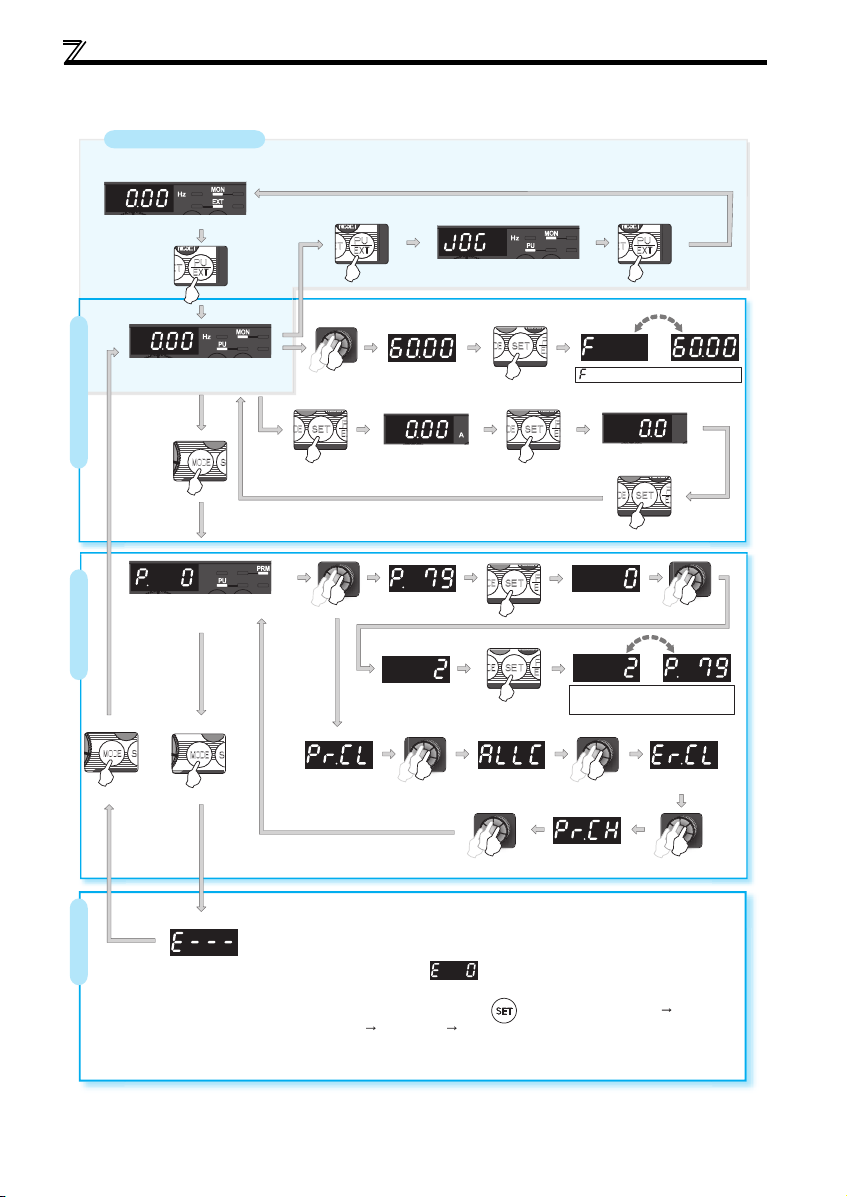
1.2.2 Basic operation (factory setting)
Operation mode switchover
At power-ON (External operation mode)
PU Jog operation mode
(Example)
PU operation mode
(output frequency monitor)
Parameter setting mode
Parameter settingFaults history Monitor/frequency setting
Value change
Output current monitor
Value change
Parameter clear All parameter
[Operation for displaying faults history]
The past eight faults can be displayed using the setting dial.
(The latest fault is ended by ".".)
When no fault history exists, is displayed.
While a fault is displayed:
The display shifts as follows by pressing : Output frequency at the fault
Output current Output voltage Energization time.
(After Energization time, it goes back to a fault display.)
Pressing the setting dial shows the fault history number.
STOP
clear
(Refer to page 35)
and frequency flicker alternately.
Frequency setting has been
written and completed!!
Output voltage monitor
Display the
present setting
(Example)
Parameter and a setting value
flicker alternately.
Parameter write is completed!!
Faults history clear
Initial value
change list
3
Page 7
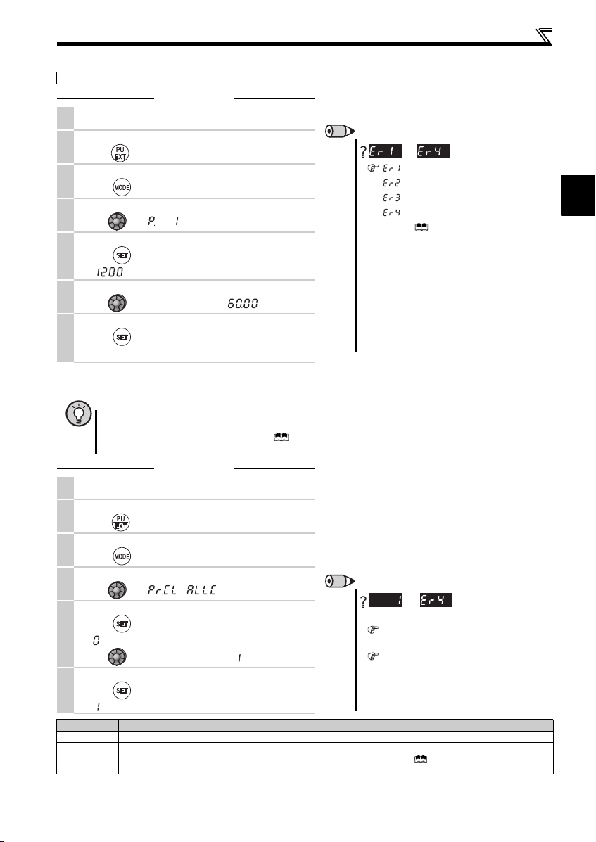
1.2.3 Changing the parameter setting value
Operation example Change the Pr. 1 Maximum frequency setting.
Operation
Screen at power-ON
1.
The monitor display app ears.
Operation mode change
2.
Press to choos e the PU operation mode. PU i ndicator is li t.
Parameter setting mode
3.
Press to choose the parameter sett ing mode.
Selecting the parameter number
4.
Turn until (Pr. 1) appears.
Reading the setting value
Press to read the present set value .
5.
" "(120.0Hz (initial value) ) appears.
Changing the setting value
6.
Turn to c hange the set value to " " (60.00Hz).
Setting the parameter
Press to set.
7.
The parameter number an d the setting value flicker alte rnately.
1.2.4 Parameter clear/all parameter clear
POINT
y Set "1" in Pr.CL Parameter clear or ALLC all parameter clear to initialize parameters. (Parameters are not cleared
when "1" is set in Pr. 77 Parameter write selection.)
y Refer to the extended parameter list of the Instruction Manual (Applied) for parameters cleared with this
operation.
Operation
Screen at power-ON
1.
The monitor display app ears.
Operation mode change
2.
Press to choose the PU operation mode. PU indicator is lit.
Parameter setting mode
3.
Press to choose the parameter sett ing mode.
Selecting Parameter Clear (All Parameter Clear)
4.
Turn until ( ) appe ars.
Selecting the setting value
Press to read the present set value .
5.
" "(initial value) appears.
Turn to c hange it to the set value " ".
Executing Parameter Clear
6.
Press to set.
" " and Pr. CL (ALLC) indications flicker alterna tely.
Setting Description
0 Clear is not executed.
Sets parameters back to th e initial values. (Parame ter clear sets back all paramete rs except calibrati on parameters,
1
terminal function selection parameters to the initial values.) Refer to the parameter list of the Instructi on Manual (Applied) for
availability of parameter clear and all parameter cle ar.
Operation panel
REMARKS
to
appears .....Write disable error
appears
appears .....Calibration error
appears .....Mode designatio n error
(For details, refer to the Inst ruction Manual
(Applied).)
y The number of digits displayed on the ope ration
panel is four. Only the upper four digits of values can
be displayed and set. If the values to be displayed
have five digits or more including decimal places, the
fifth or later numerals cannot be displayed nor set.
(Example) For Pr. 1
When 60Hz is set, 60.00 is d isplayed.
When 120Hz is set, 120.0 is displayed and s econd
decimal place is not displayed nor set.
REMARKS
and
Why?
The inverter is not in the PU operation mode.
(Refer to the step 2. )
PU connector is us ed (when a parameter unit
(FR-PU04/FR-PU07) is us ed).
y Stop the inverter. Parameter clear is unavailable
when the inverter is running, and will cause the write
disable error.
is displayed...Why?
..... Write error during operation
are displayed al ternately ...
1
4
Page 8
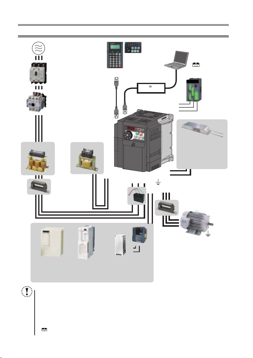
2 INSTALLATION AND WIRING
AC power supply
Use within the permissible power supply
specifications of the inverter. To ensure
safety, use a moulded case circuit breaker,
earth leakage circuit breaker or magnetic
contactor to switch power ON/OFF.
(Refer to page 40)
Moulded case circuit breaker
(MCCB) or earth leakage circuit
breaker (ELB), fuse
The breaker must be selected carefully
since an in-rush current flows in the
inverter at power on.
(Refer to page 6)
Magnetic contactor (MC)
Install the magnetic contactor to ensure
safety. Do not use this magnetic contactor
to start and stop the inverter. Doing so will
cause the inverter life to be shortened.
(Refer to page 6)
Reactor (FR-HAL, FR-HEL option)
Reactors (option) must be used when
power harmonics measures are taken,
the power factor is to be improved or the
inverter is installed near a large power
supply system (500kVA or more). The
inverter may be damaged if you do not
use reactors. Select the reactor according
to the model. Remove the jumpers across
AC reactor (FR-HAL)
* Filterpack (FR-BFP2), which contains DC reactor and noise filter in one package, is also available.
terminals P/+ and P1 to connect the DC reactor.
Install a noise filter (ferrite core)
to reduce the electromagnetic
noise generated from the
inverter. Effective in the range
from about 1MHz to 10MHz.
When more wires are passed
through, a more effective result
can be obtained. A wire should
be wound four turns or more.
High power factor
converter (FR-HC)
Power supply harmonics
can be greatly suppressed.
Install this as required.
DC reactor (FR-HEL) *
Noise filter (ferrite core) *
(FR-BSF01, FR-BLF)
Power regeneration
common converter
(FR-CV)
Great braking capability
is obtained.
Install this as required.
Parameter unit
(FR-PU07)
P/+
P1
Resistor unit (FR-BR)
Discharging resistor (GZG, GRZG)
The regenerative braking capability
of the inverter can be exhibited fully.
Install this as required.
NOTE
y
The life of the inverter is influenced by surrounding air temperature. The surrounding air temperature should be as low as
possible within the permissible range. This must be noted especially when the inverter is installed in an enclosure.
y Wrong wiring might lead to damage of the inverter. The control signal lines must be kept fully away from the main
circuit to protect them f rom noise. (Refer to page 8)
y Do not install a power factor correction capacitor, surge suppressor or noise filter (capacitor) on the inverter output
side. This will cause the inverter to trip or the capacitor and surge suppressor to be damaged. If any of the above
devices are connected, immediate ly remove them.
y Electromagnetic wave interference
The input/output (main circuit) of the inverter includes high frequency components, which may interfere with the
communication device s (such as AM radios) used near the inverter. In this case, install the FR-BIF optiona l
(capacitor)
(for use in the input side only) or FR-BSF01 or FR-BLF
(
Refer to Chapter 3 of the Instructio n Manual (Applied)
y Refer to the Instruction Manual of each option and peripheral devices for details of peripheral devices.
Enclosure surface operation
panel (FR-PA07)
By connecting the connection cable
(FR-CB2) to the PU connector,
operation can be performed from
FR-PU07, FR-PA07.
Inverter (FR-D700)
Brake unit
(FR-BU2)
R/L1 S/L2T/L3
P/+
PR
Noise filter
(capacitor) *
(FR-BIF)
Reduces the
radio noise.
).
RS-485 RS-232C
PR
P/+
RS-232C - RS-485 converter is
required when connecting to PC
with RS-232C interface.
( Refer to the
Instruction Manual (Applied))
Converter
S1
S2
SC
P/+
PR
Noise filter (ferrite core)
Earth (Ground)
UW
N/-
P/+
Devices connected to the output
Do not install a power factor correction capacitor,
surge suppressor or noise filter (capacitor) on the output
side of the inverter. When installing a moulded case
circuit breaker on the output side of the inverter,
contact each manufacturer for selection of the
moulded case circuit breaker.
Earth (Ground)
To prevent an electric shock, always earth (ground)
the motor and inverter. For reduction of induction noise
from the power line of the inverter, it is recommended
to wire the earth (ground) cable by returning it to the
earth (ground) terminal of the inverter.
(FR-BSF01, FR-BLF)
Install a noise filter (ferrite core)
to reduce the electromagnetic
V
noise generated from the inverter.
Effective in the range from about
1MHz to 10MHz. A wire should be
wound four turns at a maximum.
noise filter (ferrite core)
Approved safety
relay module
Required for
compliance with
safety standard.
Brake resistor (FR-ABR,
MRS type, MYS type)
Braking capability can be
improved. (0.4K o r higher)
Always install a thermal relay
when using a brake resistor
whose capacity is 11K or higher.
(Refer to page 17)
to minimize interference.
Motor
Earth (Ground)
(Refer to page 7)
noise filter
5
Page 9
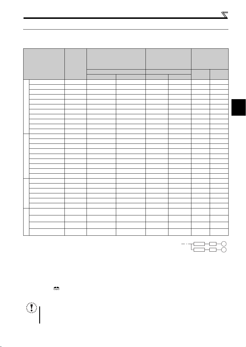
Peripheral devices
2.1 Peripheral devices
Check the inverter model of the inverter you purchased. Appropriate peripheral devices must be selected according to the capacity.
Refer to the following list and prepare appropriate peripheral devices.
Moulded Case Circuit Breaker
(MCCB) ∗1
(ELB) ∗2
(NF or NV type)
Reactor connection Reactor connection
Inverter Model
Motor
Output
(kW)
or Earth Leakage Circuit Breaker
without with without with
FR-D720-0.1K 0.1 5A 5A S-N10 S-N10 0.4K ∗5 0.4K ∗5
FR-D720-0.2K 0.2 5A 5A S-N10 S-N10 0.4K ∗5 0.4K ∗5
FR-D720-0.4K 0.4 5A 5A S-N10 S-N10 0.4K 0.4K
FR-D720-0.75K 0.75 10A 5A S-N10 S-N10 0.75K 0.75K
FR-D720-1.5K 1.5 15A 10A S-N10 S-N10 1.5K 1.5K
FR-D720-2.2K 2.2 20A 15A S-N10 S-N10 2.2K 2.2K
FR-D720-3.7K 3.7 30A 30A S-N20, S-N21 S-N10 3.7K 3.7K
FR-D720-5.5K 5.5 50A 40A S-N20, S-N21 S-N20, S-N21 5.5K 5.5K
Three-Phase 200V
FR-D720-7.5K 7.5 60A 50A S-N25 S-N20, S-N21 7.5K 7. 5K
FR-D720-11K 11 75A 75A S-N35 S-N35 11K 11K
FR-D720-15K 15 125A 100A S-N50 S-N50 15K 15K
FR-D740-0.4K 0.4 5A 5A S-N10 S-N10 H0.4K H0.4K
FR-D740-0.75K 0.75 5A 5A S-N10 S-N 10 H0.75K H0.75K
FR-D740-1.5K 1.5 10A 10A S-N10 S-N10 H1.5K H1.5K
FR-D740-2.2K 2.2 15A 10A S-N10 S-N10 H2.2K H2.2K
FR-D740-3.7K 3.7 20A 15A S-N10 S-N10 H3.7K H3.7K
FR-D740-5.5K 5.5 30A 20A S-N20, S-N21 S-N11, S-N12 H5.5K H5.5K
FR-D740-7.5K 7.5 30A 30A S-N20, S-N21 S-N20, S-N21 H7.5K H7.5K
Three-Phase 400V
FR-D740-11K 11 50A 40A S-N20, S-N21 S-N20, S-N21 H11K H 11K
FR-D740-15K 15 6 0A 50A S-N25 S-N20, S-N21 H15K H15K
FR-D720S-0.1K 0.1 5A 5A S-N10 S-N10 0 .4K ∗5 0.4K ∗5
FR-D720S-0.2K 0.2 5A 5A S-N10 S-N10 0 .4K ∗5 0.4K ∗5
FR-D720S-0.4K 0.4 10A 10A S-N10 S-N10 0.75K ∗5 0.75K ∗5
FR-D720S-0.75K 0.75 15A 10A S-N10 S-N 10 1.5K ∗5 1.5K ∗5
FR-D720S-1.5K 1.5 20A 20A S-N10 S-N10 2 .2K ∗5 2.2K ∗5
FR-D720S-2.2K 2.2 40A 30A S-N20, S-N21 S-N10 3.7K ∗5 3.7K ∗5
Single-Phase 200V
FR-D710W-0.1K 0.1 10A 5A S-N10 S-N10
FR-D710W-0.2K 0.2 10A 10A S-N10 S-N10 1 .5K ∗4, ∗5 — ∗6
FR-D710W-0.4K 0.4 15A 15A S-N10 S-N10 2 .2K ∗4, ∗5 — ∗6
FR-D710W-0.75K 0.75 30A 20A S-N10 S -N10 3.7K ∗4, ∗5 — ∗6
Single-Phase 100V
∗1 ySelect a MCCB according to the power supply capacity.
yInstall one MCCB per inverter.
∗2 For the use in the United States or Canada, select an UL and cUL certified fuse with Class T fuse equivalent cut-off
speed or faster with the appropriate rating for branch circuit protection. Alternatively, select a UL489 molded case circuit breaker (MCCB). (Refer to page 46)
∗3 Magnetic contactor is selected based on the AC-1 class. The electrical durability of magnetic contactor is 500,000 times. When the magnetic contactor is
used for emergency stop during motor driving, the electrical durability is 25 times.
If using an MC for emergency stop during motor driving, select an MC regarding the inverter input side current as JEM1038-AC-3 class rated current. When
using an MC on the inverter output side for commercial-power supply operation switching using a general purpose motor, select an MC regarding the motor
rated current as JEM1038-AC-3 class rated current.
∗4 When connecting a single-phase 100V power input model to a power transformer (50kVA or more), install an AC reactor (FR-HAL) so that the performance
is more reliable. ( Refer to Chapter 3 of the Instruction Manual (Applied))
∗5 The power factor may be slightly lower.
∗6 Single-phase 100V power input model is not compatible with DC reactor.
NOTE
y When the inverter capacity is larger than the motor capacity, select an MCCB and a magnetic contactor according to the inverter model,
and cable and reactor according to the motor output.
y When the breaker on the inverter input side trips, check for the wiring fault (short circuit), damage to internal parts of the inverter, etc.
Identify the cause of the trip, then remove the cause and power ON the breaker.
Magnetic Contactor (MC)
∗3
Reactor
FR-HAL FR-HEL
0.75K
∗4, ∗5
— ∗6
MCCB INV
MCCB INV
IM
IM
2
6
Page 10
Installation of the inverters and precautions
2.2 Installation of the inverters and precautions
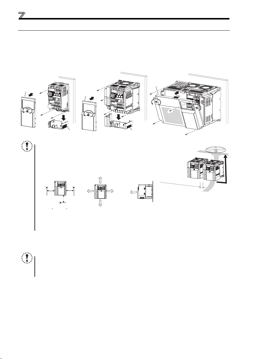
(1) Installation of the inverter
Enclosure surface mounting
Remove the front cover and wiring cover to mount the inverter to the surface. (Remove the covers in the directions of the
arrows.)
FR-D720-0.1K to 0.75K
FR-D720S-0.1K to 0.75K
FR-D710W-0.1K to 0.4K
Front cover
NOTE
y When encasing multiple inverters, install them in paral lel as a cooling
measure.
y Install the inverter vertically.
y For heat dissipation and maintenance, allow minimum clearance shown
in the figures below fro m the inverter to the other devices and to the
inner surface of the enclosure.
5cm
Measurement
position
-10 C to +50 C
(non-freezing)
∗1 Allow 5cm or more clearance for 5.5K or higher.
∗2 When using the inverters at the surrounding air temperature of 40°C or less, the inverters can be installed without any clearance between
them (0cm clearance).
5cm
(2) Environment
Before installation, che ck that the environment meets the specifications on page 41.
Note
y Install the inverter on a strong surface securely and vertically with bolts.
y Leave enough clearances and take cooling measures.
y Avoid places where the inverter is subjected to direct sunlight, high temperature and high humidity.
y Install the inverter on a nonflammable wall surface.
FR-D720-1.5K to 3.7K
FR-D740-0.4K to 3.7K
FR-D720S-1.5K, 2.2K
FR-D710W-0.75K
Front cover
Wiring cover Wiring cover
Measurement
position
5cm
1cm or
more
∗1, ∗2
10cm or more
1cm or
∗1, ∗2
more
10cm or more
1cm or
more
∗1
FR-D720-5.5K to 15K
FR-D740-5.5K to 15K
Front cover
Refer to the clearances below.
7
Page 11
2.3 Wiring
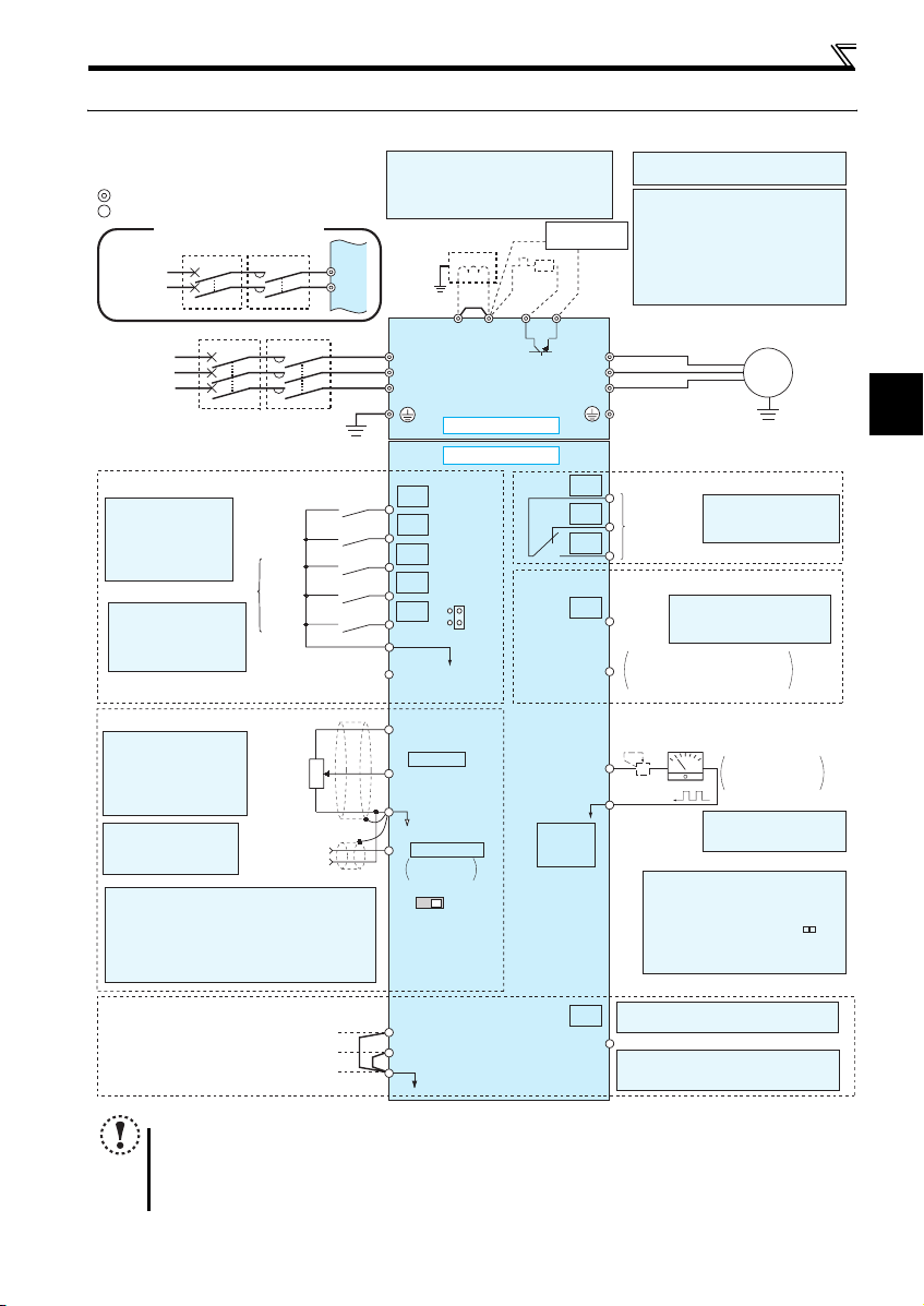
2.3.1 Terminal connection diagram
Sink logic
Main circuit terminal
Control circuit terminal
Single-phase power input
Single-phase
AC power
supply
Three-phase
AC power
supply
Control input signals (No voltage input allowed)
The function of these
terminals can be
changed to the reset
signal, etc. with the input
terminal assignment
(Pr. 178 to Pr. 182)
*2 When using terminals PC-
SD as a 24VDC power
supply, take care not to
short across terminals
PC and SD.
Frequency setting signals (Analog)
*3 Terminal input specifications
can be changed by analog
input specifications
switchover (Pr. 73).
Terminal 10 and terminal 2
are used as PTC input
terminal (Pr. 561).
*4 It is recommended to
use 2W1kΩ when the
frequency setting signal
is changed frequently.
*5 Terminal input specifications can be changed by analog
input specifications switchover (Pr. 267). Set the
voltage/current input switch in the "V" position to select
voltage input (0 to 5V/0 to10V) and "I" (initial value) to
select current input (4 to 20mA).
To use terminal 4 (initial setting is current input), set "4"
in any of Pr.178 to Pr.182 (input terminal function
selection) to assign the function, and turn ON AU signal.
MCCB MC
MCCB MC
Earth
(Ground)
Forward
rotation start
Reverse
rotation start
High
.
Multi-speed selection
speed
Middle
speed
Low
speed
Contact input common
(Common for external power supply transistor)
24VDC power supply
3
Frequency
setting
potentiometer
1/2W1kΩ
*4
1
Terminal 4
(+)
input
(-)
(Current
input)
R/L1
S/L2
(Ground)
2
*
1. DC reactor (FR-HEL)
When connecting a DC reactor, remove the
jumper across P1 and P/+.
Single-phase 100V power input model is not
compatible with DC reactor.
Earth
R/L1
S/L2
T/L3
Jumper
*1
P1 P/+
*6
R
*7
PR
N/-
Main circuit
Control circuit
STF
STR
RH
RM
RL
SD
PC
10(+5V)
2 0 to 5VDC
(0 to 10VDC)
5(Analog common)
4 4 to 20mADC
0 to 5VDC
0 to 10VDC
VI
Voltage/current
input switch
*2
SOURCE
*5
*3
SINK
*5
connector
Brake unit
(Option)
RUN
PU
*9
*6 Terminal P1 is not available for single-
phase 100V power input model.
*7 Brake resistor (FR-ABR, MRS type, MYS
type)
Install a thermal relay to prevent an
overheat and burnout of the brake resistor.
Always install a thermal relay when using
a brake resistor whose capacity is 11K or
higher.
(The brake resistor can not be connected
to the 0.1K and 0.2K.)
U
V
W
C
B
A
Relay output
(Fault output)
Relay output
Open collector output
Terminal functions vary by
Pr. 190 RUN terminal function
Running
selection
Open collector output common
SE
Sink/source common
Calibration resistor
+
-
FM
*8
SD
*9 Operation and parameter setting can be
done from the parameter unit (FRPU07) and the enclosure surface
operation panel (FR-PA07).
(Use the option cable (FR-CB2 ).)
RS-485 communication can be utilized
from a personal computer and other
devices.
Wiring
Motor
IM
Earth (Ground)
Terminal functions vary
by Pr. 192 A,B,C terminal
function selection
Indicator
(Frequency meter, etc.)
Moving-coil type
1mA full-scale
*8 It is not necessary when
calibrating the indicator
from the operation panel.
2
Safety stop signal
Safe stop input (Channel 1)
Safe stop input (Channel 2)
Safe stop input common
NOTE
y To prevent a malfunction caus ed by noise, separate the signal c ables more than 10cm from the power cables. Also
separate the main circuit w ire of the input side and t he output side.
y After wiring, wire off cuts must not be left in the inverter.
Wire offcuts can cause an alarm, failure or malfunction. Always keep the inverter clean. When drilling mounting holes
in an enclosure etc., take ca re not to allow chips and other foreign matter to enter the inverter.
y The output of the single-phase power input model is three-phase 200V.
Shorting
wire
Terminal functions vary by Pr. 197 SO
S1
S2
SC
SO
terminal function selection
Safety monitor output *10
*10 Common terminal of terminal SO is
terminal SC. (Connected to terminal SD
inside of the inverter.)
8
Page 12
Wiring
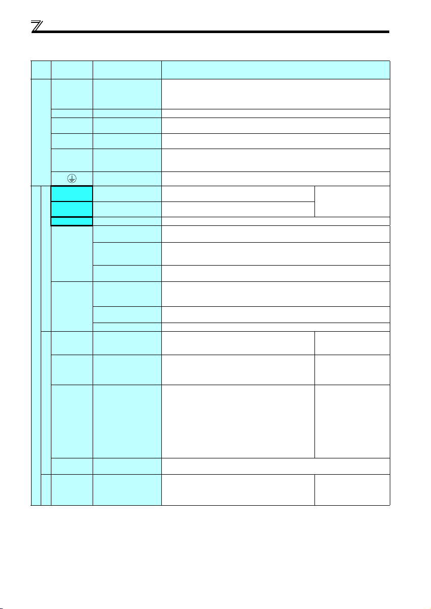
2.3.2 Terminal specifications
Terminal
Typ e
Symbol
R/L1, S/L2,
T/L3
U, V, W Inverter output
P/+, PR Brake resistor connection
P/+, N/- Brake unit connection
Main circuit terminal
P/+, P1 ∗ DC reactor connection
STF Forward rotation start
STR Reverse rotation start
RH, RM, RL Multi-speed selection
SD
Contact input
PC
10
2
Control circuit terminal/Inpu t signal
4
Frequency setting
5
10
2
Thermistor
Terminal Name Terminal Specification
∗
AC power input
Earth (Ground)
Contact input common
(sink) (initial setting)
External transistor
common (source)
24VDC power supply
common
External transistor
common (sink)
(initial setting)
Contact input common
(source)
24VDC power supply
Frequency setting power
supply
Frequency setting
(voltage)
Frequency setting
(current)
Frequency setting
common
PTC thermistor input
Connect to the commercial power supply.
Do not connect anything to these terminals when using the high power factor converter (FRHC) or power regeneration common converter (FR-CV).
* When using single-phase power inpu t, terminal s are R/L1 and S/L2.
Connect a three-phase squirrel-cage motor.
Connect a brake resistor (FR-ABR, MRS type, MYS type) across terminals P/+ and PR.
(The brake resistor can not be connected to the 0.1K and 0.2K.)
Connect the brake unit (FR-BU2), power regeneration common converter (FR-CV) or high
power factor converter (FR-HC).
Remove the jumper across terminals P/+ and P1 and connect a DC reactor. (Single-phase
100V power input model is not compatible with the DC reactor.)
* Terminal P1 is not available for single-phase 100V power input model.
For earthing (grounding) the inverter chassis. Must be earthed (grounded).
Turn ON the STF signal to start forward rotati on and turn it OFF
to stop.
Turn ON the STR signal to start reverse rotation and turn it
OFF to stop.
Multi-speed can be selected according to the combination of RH, RM and RL signals.
Common terminal for contact input terminal (sink logic) and terminal FM.
Connect this terminal to the power supply common terminal of a transistor output (open
collector output) device, such as a programmable controller, in the source logic to avoid
malfunction by undesirable current.
Common output terminal for 24VDC 0.1A power supply (PC terminal).
Isolated from terminals 5 and SE.
Connect this terminal to the power supply common terminal of a transistor output (open
collector output) device, such as a programmable controller, in the sink logic to avoid
malfunction by undesirable current.
Common terminal for contact input terminal (source logic).
Can be used as 24VDC 0.1A power supply.
Used as power supply when connecting potentiometer for
frequency setting (speed setting) from outside of the inverter.
Inputting 0 to 5VDC (or 0 to 10V) provides the maximum output
frequency at 5V (10V) and makes input and output
proportional. Use Pr. 73 to switch between input 0 to 5VDC
input (initial setting) and 0 to 10VDC.
Inputting 4 to 20mADC (or 0 to 5V, 0 to 10V) provides the
maximum output frequency at 20mA and makes input and
output proportional. This input signal is valid only when the AU
signal is ON (terminal 2 input is invalid). To use terminal 4
(initial setting is current input), set "4" in any of Pr.178 to Pr.182
(input terminal function selecti on) to assign the function, and turn
ON AU signal.
Use Pr. 267 to switch among input 4 to 20mA (initial setting), 0
to 5VDC and 0 to 10VDC. Set the voltage/current input switch
in the "V" posit ion to select volta ge input (0 to 5V/0 to 10V).
Frequency setting signal (terminal 2, 4) common terminal. Do not earth (ground).
For connecting PTC thermistor output.
When PTC thermistor protection is valid (Pr. 561 ≠ "9999"),
terminal 2 is not available for frequency setting.
When the STF and STR
signals are turned ON
simultaneously, the stop
command is given.
5VDC
permissible load current
10mA
Input resistance10kΩ ± 1kΩ
Permissible maximum voltage
20VDC
Current input:
Input resistance 249Ω ± 5Ω
Maximum permissible current
30mA
Voltage input:
Input resistance10kΩ ± 1kΩ
Permissible maximum voltage
20VDC
Adaptive PTC th ermistor
specification
Heat detection resistance :
500Ω to 30kΩ (Set by Pr. 561)
9
Page 13
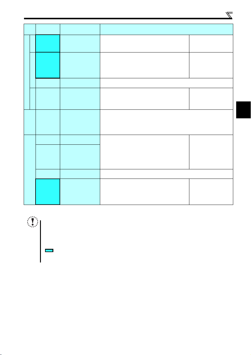
Wiring
Ter min al
Typ e
Symbol
A, B, C
Relay
RUN Inverter running
Open collector
SE
Control circuit terminal/Outp ut signal
FM For meter
Pulse
— PU co nnector
Communication
S1
S2
SC
Safety stop function *
SO
* For more details, refer to the Safety stop function instruction manual (BCN-A211508-000). (Please contact your sales representative for the manual.)
NOTE
y To change the input specification for terminal 4, set Pr. 267 and the voltage/current input switch correctly, then input
the analog signal relevant to the setting. Applying a voltage with voltage/current input switch in "I" position (current
input is selected) or a current with switch in "V" position (voltage input is selected) could cause component damage
to the inverter or analog circuit of output devices.
y Connecting the power supply to the inverter output terminals (U, V, W) will damage the inverter. Do not per form such
wiring.
y indicates that terminal functions can be selected using Pr. 178 to Pr. 182, Pr. 190, Pr. 192, Pr. 197 (I/O terminal
function selection).
y The terminal names and functions shown here are the initial settings.
Terminal Name Terminal Specification
Relay output
(fault output)
Open collector output
common
Safety stop input
(Channel 1)
Safety stop input
(Channel 2)
Safety stop input terminal
common
Safety monitor output
(open collector output)
1 changeover contact output indicates that the inverter
protective function has activated and the output stopped.
Fault: discontin uity across B-C ( continuity across A -C),
Normal: continuity across B-C (discontinuity across A-C)
Switched Low when the inverter output frequency is equal to or
higher than the starting frequency (initial value 0.5Hz).
Switched High during stop or DC injection brake operation.
(Low is when the open collector output transistor is ON
(conducts). High is when the transistor is OFF (does not
conduct).)
Common terminal of terminal RUN.
Used to output a selected monitored item (such as Output
frequency) among several monitored items.
(Not output during inverter reset.)
The output signal is proportional to the magnitude of the
corresponding monitored item.
With the PU connector, communication can be established through RS-485.
yConforming standard: EIA-485 (RS-485)
yTransmission format: Multidrop link
yCommunication speed: 4800 to 38400bps
yOverall length: 500m
Terminals S1 and S2 are for safety stop in put signals used with
the safety relay module. Terminals S1 and S2 are used
simultaneously (dual channel). Inverter output is shut off by
shortening/opening across terminals S1 and SC and across S2
and SC. In the initial status, term inals S1 and S2 are shorted
with terminal SC by shortening wire.
Remove the shortening wire and connect the safety relay
module when using the safety stop function.
Common terminal for terminals S1, S2 and SO. Connected to terminal SD inside of the
inverter.
The signal ind icates the stat us of safety stop i nput.
Low indicates safe state, and High indicates drive enabled or
fault detected.
(Low is when the open collector output transistor is ON
(conducts). High is when the transistor is OFF (does not
conduct).)
Contact capacity:230VAC
0.3A (power factor =0.4)
30VDC 0.3A
Permissible load 24VDC
(maximum 27VDC) 0.1A
(a voltage drop is 3.4V
maximum when the signal is
ON)
Permissible load current 1mA
1440 pulses/s at 60Hz
Input resistance 4.7kΩ
Voltage when contacts are
open
21 to 26VDC
When contacts are shortcircuited
4 to 6mADC
Permissible load 24VDC
(maximum 27VDC) 0.1A
(a voltage drop is 3.4V
maximum when the signal is
ON)
2
10
Page 14
Wiring
r
r
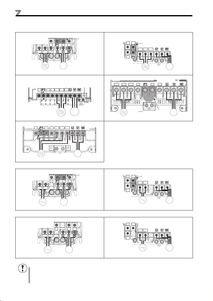
2.3.3 Terminal arrangement of the main circuit terminal, power supply and the motor wiring
zThree-phase 200V/400V class
FR-D720-0.1K to 0.75K FR-D720-1.5K to 3.7K
N/-
P/+ PR
R/L1 S/L2 T/L3
Jumpe
FR-D740-0.4K to 3.7K
N/-
PR
P/+
R/L1 S/L2 T/L3
Jumper
IM
MotorPower supply
FR-D720-5.5K, 7.5K
FR-D740-5.5K, 7.5K
N/-
Jumper
P/+ PR
R/L1 S/L2 T/L3
FR-D720-11K, 15K
R/L1 S/L2 T/L3
IM
FR-D740-11K, 15K
N/-
Jumper
Power supply
zSingle-phase 200V class
FR-D720S-0.1K to 0 .75K FR-D720S-1.5K, 2.2K
R/L1 S/L2
zSingle-phase 100V class
FR-D710W-0.1K to 0.4K FR-D710W-0.75K
P/+
N/-
R/L1 S/L2
PR
Power supply Motor
R/L1 S/L2 T/L3
P/+ PR
IM
MotorPower supply
N/-
P/+ PR
IM
Motor
Jumpe
N/-
PR
N/-
PR
Power supply
N/-
P/+
R/L1 S/L2
P/+
R/L1 S/L2
Jumper
P/+
PR
Jumper
IM
Motor
IM
MotorPower supply
IM
MotorPower supply
IM
MotorPower supply
NOTE
y Make sure the power cables are connected to the R/L1, S/L2, T/L3. (Phase need not be matched.) Never connect the
power cable to the U, V, W of the inverter. Doing so w ill damage the inverter.
y Connect the moto r to U, V, W. Turning ON the forward ro tation switch (signal) at t his time rotates the motor
counterclockwise when viewed from the load shaft.
11
IM
MotorPower supply
Page 15
Wiring
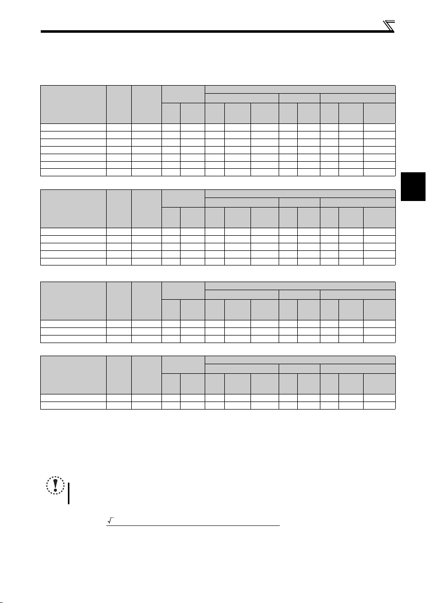
(1) Cable sizes etc., of the main control circuit terminals and earth (ground) terminals
Select the recommended cable size to ensure that a voltage drop will be 2% or less.
If the wiring distance is long between the inverter and motor, a main circuit cable voltage drop will cause the motor torque to
decrease especially at the output of a low frequency.
The following table indicates a selection example for the wiring length of 20m.
Three-phase 200V class (when input power supply is 220V)
N·m
Crimping
Terminal
R/L1
S/L2
T/L3
HIV Cables, etc. (mm2) ∗1
R/L1
U, V, W
S/L2
T/L3
U, V, W
Earthing
(grounding)
Ter mi nal
Applicable Inverter
Model
FR-D720-0.1K to 0.75K M3.5 1.2 2-3.5 2-3.5 2 2 2 14 14 2.5 2.5 2.5
FR-D720-1.5K, 2.2K M4 1.5 2-4 2-4 2 2 2 14 14 2.5 2.5 2.5
FR-D720-3.7K M4 1.5 5.5-4 5.5 -4 3.5 3.5 3.5 12 12 4 4 4
FR-D720-5.5K M5 2.5 5.5-5 5.5 -5 5.5 5.5 5.5 10 10 6 6 6
FR-D720-7.5K M5 2.5 14-5 8- 5 14 8 5.5 6 8 16 1 0 6
FR-D720-11K M5 2.5 14-5 14-5 14 14 14 6 6 1 6 16 16
FR-D720-15K M6 (M5) 4.4 22-6 22-6 22 22 14 4 4 25 25 16
Screw
Size ∗4
Tightening
Tor que
Three-phase 400V class (when input power supply is 440V)
N·m
Crimping
Terminal
R/L1
S/L2
T/L3
HIV Cables, etc. (mm2) ∗1
R/L1
U, V, W
S/L2
T/L3
U, V, W
Earthing
(grounding)
Ter mi nal
Applicable Inverter
Model
FR-D740-0.4K to 3.7K M4 1.5 2-4 2-4 2 2 2 14 14 2.5 2.5 2.5
FR-D740-5.5K M4 1.5 5.5-4 2-4 3.5 2 3.5 12 14 4 2.5 4
FR-D740-7.5K M4 1.5 5.5-4 5.5 -4 3.5 3.5 3.5 12 12 4 4 4
FR-D740-11K M4 1.5 5.5-4 5.5-4 5.5 5.5 8 10 10 6 6 10
FR-D740-15K M5 2.5 8-5 8-5 8 8 8 8 8 10 10 10
Screw
Size ∗4
Tightening
Tor que
Single-phase 200V class (when input power supply is 220V)
N·m
Crimping
Terminal
R/L1
S/L2
HIV Cables, etc. (mm2) ∗1
R/L1
U, V, W
S/L2
U, V, W
Earthing
(grounding)
Ter mi nal
Applicable Inverter
Model
FR-D720S-0.1K to 0.75K M3.5 1.2 2-3.5 2-3.5 2 2 2 14 14 2.5 2.5 2.5
FR-D720S-1.5K M4 1.5 2-4 2-4 2 2 2 14 14 2.5 2.5 2.5
FR-D720S-2.2K M4 1.5 5 .5-4 2-4 3 .5 2 3.5 12 14 4 2.5 4
Screw
Size ∗4
Tightening
Tor que
Single-phase 100V class (when input power supply is 100V)
N·m
Crimping
Terminal
R/L1
S/L2
HIV Cables, etc. (mm2) ∗1
R/L1
U, V, W
S/L2
U, V, W
Earthing
(grounding)
Ter mi nal
Applicable Inverter
Model
FR-D710W-0.1K to 0.4K M3.5 1.2 2- 3.5 2-3.5 2 2 2 14 14 2.5 2.5 2 .5
FR-D710W-0.75K M4 1.5 5.5-4 2-4 3.5 2 2 12 14 4 2.5 2 .5
∗1 The cable size is that of the cable (HIV cable (600V class 2 vinyl-insulated cable) etc.) with continuous maximum permissible temperature of 75°C. Assumes
that the surrounding air temperature is 50°C or less and the wiring distance is 20m or less.
∗2 The recommended cable size is that of the cable (THHW cable) with continuous maximum permissible temperature of 75°C. Assumes that the surrounding
air temperature is 40°C or less and the wiring distance is 20m or less. (Selection example for use mainly in the United States.)
∗3 The recommended cable size is that of the cable (PVC cable) with continuous maximum permissible temperature of 70°C. Assumes that the surrounding air
temperature is 40°C or less and the wiring distance is 20m or less. (Selection example for use mainly in Europe.)
∗4 The terminal screw size indicates the terminal size for R/L1, S/L2, T/L3, U, V, W, PR, P/+, N/-, P1 and a screw for earthing (grounding).
Screw size for earthing (grounding) the FR-D720-15K is indicated in parentheses.
For single-phase power input, the terminal screw size indicates the size of terminal screw for R/L1, S/L2, U, V, W, PR, P/+, N/-, P1 and a screw for earthing
(grounding).
Screw
Size ∗4
Tightening
Tor que
NOTE
y
Tighten the terminal screw to the specified torque. A screw that has been tightened too loosely can cause a short circuit or
malfunction. A screw that has been tightened too tightly can cause a short circuit or malfunction due to the unit breakage.
y Use crimping terminals with insulation sleeve to wire the power supply and motor.
The line voltage drop can be calculated by the following formula:
Line voltage drop [V]=
Use a larger diameter cable when the wiring distance is long or when it is desired to decrease the voltage drop (torque
reduction) in the low speed range.
3 × wire resistance[mΩ/m] × wiring distance[m] × current[A]
1000
cable
cable
cable
cable
Cable Size
AWG ∗2
R/L1
S/L2
U, V, W
T/L3
Cable Size
AWG ∗2
R/L1
S/L2
U, V, W
T/L3
Cable Size
AWG ∗2
R/L1
U, V, W
S/L2
Cable Size
AWG ∗2
R/L1
U, V, W
S/L2
PVC Cables, etc. (mm2) ∗3
R/L1
S/L2
T/L3
PVC Cables, etc. (mm2) ∗3
R/L1
S/L2
T/L3
PVC Cables, etc. (mm2) ∗3
R/L1
S/L2
PVC Cables, etc. (mm2) ∗3
R/L1
S/L2
U, V, W
U, V, W
U, V, W
U, V, W
Earthing
(grounding)
cable
Earthing
(grounding)
cable
Earthing
(grounding)
cable
Earthing
(grounding)
cable
2
12
Page 16
Wiring
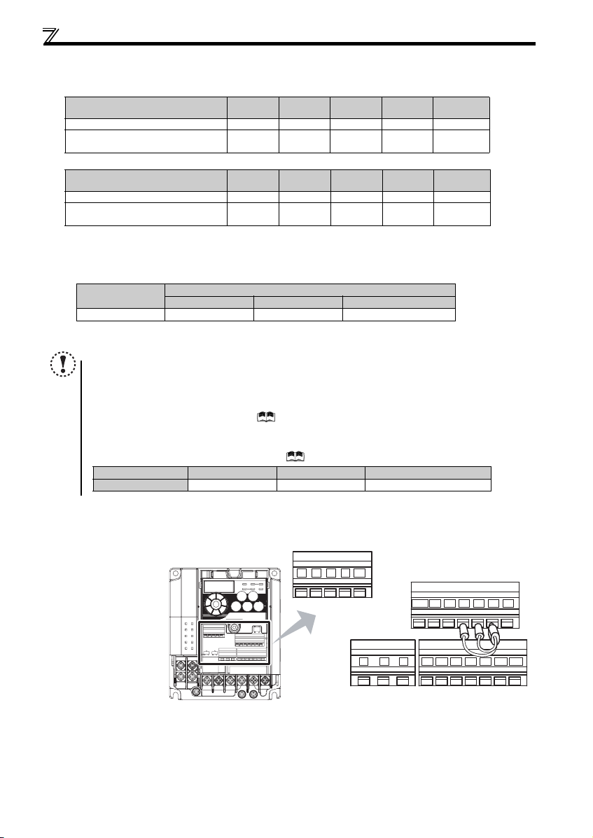
(2) Total wiring length
The overall wiring length for connection of a single motor or multiple motors should be within the value in the table below.
100V, 200V class
Pr. 72 PWM frequency selection Setting
(carrier frequency)
1 (1kHz) or less 200m 200m 300 m 500m 500m
2 to15
(2kHz to 14.5kHz)
0.1K 0.2K 0.4K 0.75K
30m 100m 200m 300m 500m
400V class
Pr. 72 PWM frequency selection Setting
(carrier frequency)
1 (1kHz) or less 200m 200m 300m 50 0m 500m
2 to15
(2kHz to 14.5kHz)
0.4K 0.75K 1.5K 2.2K
30m 100 m 200m 300m 500m
When driving a 400V class motor by the inverter, surge voltages attributable to the wiring constants may occur at the motor
terminals, deteriorating the insulation of the motor. Take the following measures 1) or 2) in this case.
1) Use a "400V class inverter-driven insulation-enhanced motor" and set frequency in Pr. 72 PWM frequency selection
according to wiring length
Wiring Length
50m or less 50m to 100m Exceeding 100m
Carrier frequency
14.5kHz or less 8kHz or less 2kHz or less
2) Connec t the surge voltage suppression filter (FR-A SF-H/FR-BMF -H) on the inverter output side.
NOTE
y Especially for long-distance wiring, the inverter may be affected by a charging current caused by the stray
capacitances of the wiring, leading to a malfunction of the overcurrent protective function, fast response current limit
function, or stall prevention function or a malfunction or fault of the equipment connected on the inverter output side.
If malfunction of fast-response current limit function occurs, disable this function. If malfunction of stall prevention
function occurs, increa se the stall level. ( Refer to Pr. 22 Stall prevention operation level and Pr. 156 Stall prevention
operation selection in the chapter 4 of the Instruction Manual (applied))
y When using the automatic restart after instantaneous power failure function with wiring length exceeding below,
select without frequen cy search (Pr. 162 = "1, 11"). (
Motor capacity 0.1kW 0.2kW 0.4kW or higher
Wiring length 20m 50m 100m
Refer to Chapter 4 of the Instruction M anual (Applied))
1.5K or
higher
3.7K or
higher
2.3.4 Wiring of control circuit
(1) Control circuit terminal layout
Recommend wire size:
0.3mm
2
to 0.75mm
2
13
10 2 5 4
FM
RUN SE S1 S2 SCSO
CBA
SD
STF
PCSDRHRMRL
STR
Page 17

Wiring
r
(2) Wiring method
zWiring
Use a blade terminal and a wire with a sheath stripped off for the control circuit wiring. For a single wire, strip off the sheath of
the wire and apply directly.
Insert the blade terminal or the single wire into a socket of the terminal.
1) Strip off the sheath about the length below. If the length of the sheath peeled is too long, a short circuit may occur
among neighboring wires. If the length is too short, wires might come off.
Wire the stripped wire after twisting it to prevent it from becoming loose. In addition, do not solder it.
Wire stripping length
2) Crimp the blade terminal.
Insert wires to a blade terminal, and check that the wires come out for about 0 to 0.5 mm from a sleeve.
Check the condition of the blade ter minal after crimping. Do not use a blade terminal of which the crimping is
inappropriate, or the face is damaged.
Wire
Shell
Sleeve
0 to 0.5mm
10mm
Damaged
Crumpled tip
Unstranded
wires
Wires are not inserted
into the shell
Blade terminals available on the market: (as of February 2012)
zPhoenix Contact Co.,Ltd.
Wire Size (mm2)
0.3 AI 0,5-10WH — —
0.5 AI 0,5-10WH — AI 0,5-10WH-GB
0.75 AI 0,75-10GY A 0,75-10 AI 0, 75-10GY-GB
1 AI 1-10RD A1-10 AI 1- 10RD/1000GB
1.25, 1.5 AI 1,5-10BK A1,5-10 AI 1,5 -10BK/1000GB
0.75 (for two wires) AI-TWIN 2 x 0, 75-10GY — —
∗1 A blade terminal with an insulation sleeve compatible with MTW wire which has a thick wire insulation
∗2 Applicable for terminal ABC.
with insulation sleeve without insulation sleeve for UL wire ∗1
Blade Terminal Model
∗2
zNICHIFU Co.,Ltd.
Wire Size (mm2)
0.3 to 0.75 BT 0.75-11 VC 0.75 NH 69
Blade terminal product
number
Insulation product number
Crimping tool
product number
3) Insert the wire into a socket.
When using a single wire or a stranded wire without a blade terminal, push an
open/close button all the way down with a flathead screw driver, and insert the wire.
Open/close button
Crimping Tool
Name
CRIMPFOX 6
2
Flathead screwdrive
NOTE
y When using a stranded wire without a blade terminal, twist enough to avoid short circuit with a nearby terminals or
wires.
y Place the f lathead screwdriver ve rtical to the open/clo se button. In case t he blade tip slips, it ma y cause damage to
inverter or injury.
14
Page 18

Wiring
r
zWire removal
Pull the wire with pushing the open/close button all the
way down firmly with a flat head screwdr iver.
Open/close button
Flathead screwdrive
(3) Control circuit common terminals (SD, 5, SE)
Terminals SD, SE and 5 are common terminals for I/O sign als.(All common terminals are isolated from each other.) Do not
earth them. Avoid connecting the terminals SD and 5 and the terminals SE and 5.
Terminal SD is a common terminal for the contact input terminals (STF, STR, RH, RM, RL) and frequency output signal (FM).
The open collector circuit is isolated from the internal control circuit by photocoupler.
Terminal 5 is a common terminal for the frequency setting signals (terminals 2 or 4). It should be protected from external noise
using a shielded or twisted cable.
Terminal SE is a common terminal for the open collector output terminal (RUN). The contact input circuit is isolated from the
internal control circuit by photocoupler.
(4) Wiring instructions
1) It is recommended to use the cables of 0.3mm2 to 0.75mm2 gauge for connection to the control circuit terminals.
2) The maximum wiring length should be 30m (200m for terminal FM).
3) Do not short across terminals PC and SD. Inverter may be damaged.
4) When using contact inputs, use two or more parallel micro-signal contacts or
twin contacts to prevent contact faults since the control circuit input signals are
micro-currents.
NOTE
y Pulling out the terminal block forcefully without pushing
the open/close button all the way down may damage the
terminal block.
y Use a small flathead scr ewdriver (Tip thickness: 0.4mm/
tip widt h: 2.5mm) .
If a flathead screwdriver with a narrow tip is used,
terminal block may be damaged.
Products available on the market :(as of Oct. 2008)
Product Ty pe Manufacturer
Flathead
screwdriver
y Place the flath ead screwdriver vertical t o the open/close
button. In case the blade tip slips, it may cause damage
to inverter or injury.
SZF 0- 0,4 x 2,5 Phoenix Contact Co.,Ltd.
5) Use shielded or twisted cables for connection to the control circuit terminals
and run them awa y from the main and power circu its (including the 200V relay
sequence circuit).
6) Do not apply a voltage to the contact input terminals (e.g. STF) of the control circuit.
7) Always apply a voltage to the fault output terminals (A, B, C) via a relay coil, lamp, etc.
Micro signal contacts Twin contacts
2.3.5 Assigning signals (output stop signal (MRS), reset signal (RES), etc.) to contact
input terminals
POINT
y Use Pr.178 to Pr.182 (input terminal function selection) to select and change the functions assigned to input
terminals.
To assign the output stop signal (MRS) to the terminal RH, for example, assign "24" to Pr.182 RH terminal
function selection. (Refer to page 4 to change a parameter setting value.)
Pr. Name
178
STF terminal function selection
179
STR terminal function selection
RL terminal function selection
180
RM terminal function selection
181
RH terminal function selection
182
NOTE
y Changing the terminal assignment using Pr.178 to Pr.182 (input terminal function selection) may affect the other functions.
Set parameters after confirming the function of each terminal.
Initial
Val ue
0: Low-speed operation com mand (RL)
60
1: Middle-speed operat ion command (RM)
2: High-speed operation command (RH)
3: Second function sele ction (RT)
61
4: Terminal 4 input selection (AU)
5: JOG operation selectio n (JOG)
0
7: External thermal relay input (OH)
8: Fifteen speed selection ( REX)
10: Inverter operation enable signal ( X10)
1
(FR-HC/FR-CV connection)
12: PU operation externa l interlock (X12)
14: PID control valid terminal (X14)
2
16: PU-External operatio n switchover (X16)
Range
18: V/F switchover (X1 8)
24: Output stop (MRS)
25: Start self-holding selection (STOP )
60: Forward rotation (STF )
61: Reverse rotation (STR) ∗2
62: Inverter reset (RES )
65: PU-NET operation s witchover (X65)
66: External-NET operation switc hover
(X66)
67: Command source swi tchover (X67)
9999: No function
∗1 Assigned to STF terminal (Pr. 178) only
∗2 Assigned to STR terminal (Pr. 179) only
∗1
15
Page 19

Wiring
2.3.6 Safety stop function
(1) Description of the function
The terminals related to the safety stop function are shown below.
Ter min al
Symbol
S1 ∗1 For input of safety stop c hannel 1. Between S1 and SC / S 2 and SC
S2
∗1 For input of safety stop channel 2.
For output of safety stop c ondition.
SAFE
SO
∗2
RUN
∗3
∗1 In the initial status, terminal S1 and S2 are shorted with terminal SC by shortening wire. Remove the shortening wire and connect the safety relay module
when using the safety stop function.
∗2
In the initial setting, safety monitor output signal (SAFE signal) is assigned to terminal SO. The function can be assigned to other terminals by setting "80 (positive
logic) or 180 (negative logic)" to any of
∗3 In the initial setting, inverter running (RUN signal) is assigned to terminal RUN. Set "81" to Pr. 190 RUN terminal function selection to assign SAFE2 signal. The
function can be assigned to other terminals by setting "81 (positive logic) or 181 (negative logic)" to any of Pr. 190, Pr. 192 or Pr. 197 (Output terminal function
selection). ( Refer to Chapter 4 of the Instruction Manual (Applied))
∗4 At an internal safety circuit fault, E.SAF or E.CPU is displayed on the operation panel.
The signal is output when i nverter output is shut off due to the safety stop
signal
function.
SC Common terminal for S1,S2,SO signals. (SC is co nnected terminal SD internally.) —
SAFE2
Outputs when an alarm or failure is detected
signal
Outputs when there is no inte rnal safety circuit fault
SE Com mon terminal for open collec tor outputs (terminal RUN) —
Pr. 190, Pr. 192 or Pr. 197 (Output terminal function selection)
NOTE
y Use SAFE signal for the purpose to monitor safety stop status. SAFE signal cannot be used as safety stop input
signal to other devices (other than the safety relay module.)
y SAFE2 signal can only be used to output an alarm or to prevent restart of an inverter. The signal cannot be used as
safety stop input sig nal to other devices.
(2) Wiring connection diagram
To prevent restart at fault occurrence,
connect terminals RUN (SAFE2 signal) and
SE to terminals XS0 and XS1, which are the
feedback input terminals of the safety relay
module.
By setting Pr.190 RUN terminal function
selection = "81 (SAFE2 signal)", terminal
RUN is turned OFF at fault occurrence.
∗1 Output signals differ by the setting of Pr. 190, Pr.
192 and Pr. 197 (Output terminal function selection).
∗2 Input signals differ by the setting of Pr. 178 to Pr.
182 (Input terminal function s election).
NOTE
y Changing the terminal assignment using Pr. 190, Pr. 192, and Pr. 197 (output terminal function selection) may affect the
other functions. Set parameters after confirming the function of each terminal.
(3) Safety stop function operation
Input power
O F F ----- ----- ----- O F F O F F O u tp u t sh u t of f ( Sa f e st a t e )
Input signal
S1-SC S2- SC SAFE∗3 SAFE2∗3
Short Short
ON
∗1 At an internal safety circuit fault, E.SAF or E.CPU is displayed on the operation panel.
∗2 SA is displayed on the operation panel when both the S1 and S2 signals are in the open state without any internal safety circuit fault (E.SAF, E.CPU).
∗3 ON: Transistor used for an open collector output is conducted.
OFF: Transistor used for an open collector output is not conducted.
For more details, refer to the Safety stop function instruction manual (BCN-A211508-000). (Please contact your sales representa tive
for the manual.)
Open Open
Short Open N/A OFF OFF Output s hutoff (Safe state)
Open
Internal safety
Short N/A OFF OFF Output shutoff (Safe state)
y
Pr. 178
y
Pr. 179
y
Pr. 190
y
Pr. 197
DC24V
MITSUBISHI MELSEC Safety relay module
" N/A " denotes a condi tion where circuit fault does not apply.
circuit∗1
No failure OFF ON Drive enabled
Detected O FF OFF Outp ut shutoff (Safe state)
No failure∗2 ON ON Output shutoff (Safe state)
Detected O FF OFF Outp ut shutoff (Safe state)
Description
∗4
= "60 (initial value)"
= "25"
= "81"
= "80 (initial value)"
START/RESET
Emergency
stop button
COM0
+24V
X0 X1
Internal
Safety
Circuit
24G
QS90SR2SN-Q
Output signal
Open: In safety stop mode.
Short: Other than safety stop mode.
OFF: Drive enabled, or drive stop (at
an internal safety circui t fault
ON: Drive stop (no internal safety
OFF: Internal safety cir cuit fault ∗4
ON: No internal safety circuit fault ∗4
. (
Refer to Chapter 4 of the Instruction Manual (Applied)
∗1
SO (SAFE)
monitor
∗1
RUN (SAFE2)
SE
STF
∗2
STF
STR(STOP)
STOP
COM1
XS0
XS1
Z10
Z00
K1
K2
Z11 Z01 Z21
S1
S2
SC
Z20
SD
circuit fault
I/O control
∗2
∗4)
Inverter
Output
shutoff
circuit
R/L1
S/L2 T/L3
U V W
∗4)
)
IM
Operation state
2
16
Page 20

Connection of a dedicated external brake resistor (MRS type, MYS type, FR-ABR)
r
2.4 Connection of a dedicated external brake resistor (MRS type, MYS type, FR-ABR)
Install a dedicated brake resistor (MRS type, MYS type, FR-ABR) outside when the motor driven by the inverter is made to run
by the load, quick deceleration is required, etc. Connect a dedicated brake resistor (MRS type, MYS type, FR-ABR) to
terminal P/+ and PR. (For the locations of terminal P/+ and PR, refer to the terminal block layout (page 11).)
Set parameters below. (
Connected Brake Resistor Pr. 30 Regenerative function selection Setting Pr. 70 Special regenerative brake duty Setting
MRS type, MYS type 0 (initial value) —
MYS type
(used at 100% torque/6%ED)
FR-ABR 1
z It is recommended to configure a sequence, which shuts off power in the input side of the inverter by the external thermal
relay as shown below, to prevent overheat and burnout of the brake resistor (MRS type, MYS type) and high duty brake
resistor (FR-ABR) in case the regenerative brake transistor is damaged. (The brake resistor cannot be connected to the
0.1K and 0.2K.)
<Example 1>
Power supply
ON
∗1 Refer to the table below for the type number of each capacity of thermal relay and the diagram below for the connection.
(Always install a thermal relay when using a brake resistor whose capacity is 11K or higher.)
∗2 When the power supply is 400V class, install a step-down transformer.
Power
Supply
Vol tag e
100V,
200V
Power
Supply
Vol tag e
100V,
200V
400V
MC
Brake Resistor
MRS120W200 TH-N 20CXHZ-0.7A
MRS120W100 TH-N 20CXHZ-1.3A
MRS120W60 TH-N20 CXHZ-2.1A
MRS120W40 TH-N20 CXHZ-3.6A
MYS220W50
(two units in para llel)
High-duty
Brake Resistor
FR-ABR-0.4K TH-N20CXHZ-0.7A
FR-ABR-0.75K TH-N20CXHZ-1.3A
FR-ABR-2.2K TH-N20CXHZ-2.1A
FR-ABR-3.7K TH-N20CXHZ-3.6A
FR-ABR-5.5K TH-N20CXHZ-5A
FR-ABR-7.5K TH-N20CXHZ-6.6A
FR-ABR-11K TH-N20CXHZ-11A
FR-ABR-15K TH-N20CXHZ-11A
FR-ABR-H0.4K T H-N20CXHZ-0.24A
FR-ABR-H0.75K TH-N20CXHZ-0.35A
FR-ABR-H1.5K T H-N20CXHZ-0.9A
FR-ABR-H2.2K T H-N20CXHZ-1.3A
FR-ABR-H3.7K T H-N20CXHZ-2.1A
FR-ABR-H5.5K T H-N20CXHZ-2.5A
FR-ABR-H7.5K T H-N20CXHZ-3.6A
FR-ABR-H11K TH-N20CXHZ-6.6A
FR-ABR-H15K TH-N20CXHZ-6.6A
NOTE
y The brake resistor connected should only be the dedicated brake resistor.
y Perform wiring and operation according to the Instruction Manual of each option unit.
Brake resistor cannot be used with the brake unit, high power factor converter, power supply regeneration converter, etc.
y
y Do not use the brake resistor with a lead wir e extended.
y Do not connect a resistor directly to termin als P/+ and N/-. This cou ld cause a fire.
Refer to the Instruction Manual (Applied) for the parameter details.)
16%
Thermal re lay
MC
Inverter
P/+
R/L1
S/L2
PR
T/L3
*2
T
F
MC
OFF
OCR
Contact
(Mitsubishi product)
High-duty brake
(OCR) (*1)
resistor (FR-ABR)
R
Thermal Relay Type
<Example 2>
Power supply
Contact Rating
110VAC 5A,
220VAC 2A(AC11 class)
110VDC 0.5A,
220VDC 0.25A(DC11class)
TH-N20CXHZ-5A
Thermal Relay Type
(Mitsubishi product)
Contact Rating
110VAC 5A,
220VAC 2A(AC11 class)
110VDC 0.5A,
220VDC 0.25A(DC11 class)
7.5K or lower 10%
11K or higher 6%
MC
Inverter
P/+
R/L1
S/L2
PR
T/L3
*2
T
F
ON
MC
B
MC
OFF
C
OCR
Contact
To the inverter
terminal P/+
Thermal relay
High-duty brake
(OCR) (*1)
resistor (FR-ABR)
R
1/L1 5/L3
TH-N20
2/T1 6/T3
To a resisto
17
Page 21

PRECAUTIONS FOR USE OF THE INVERTER
3 PRECAUTIONS FOR USE OF THE INVERTER
The FR-D700 series is a highly reliable product, but using incorrect peripheral circuits or incorrect operation/handling methods
may shorten the product life or damage the product.
Before starting operation, always recheck the following items.
(1) Use crimping terminals with insulation sleeve to wire the power supply and motor.
(2) Application of power to the output terminals (U, V, W) of the inverter will damage the inverter. Never perform
such wiring.
(3) After wiring, wire offcuts must not be left in the inverter.
Wire offcuts can cause an alarm, failure or malfunction. Always keep the inverter clean.
When drilling mounting holes in an enclosure etc., take care not to allow chips and other foreign matter to enter the
inverter.
(4) Use cables of the appropriate size to make a voltage drop of 2% or less.
If the wiring distance is long between the inverter and motor, a main circuit cable voltage drop will cause the motor torque
to decrease especially at the output of a low frequency. Refer to page 12 for the recommended wire sizes.
(5) The total wiring length should be within the prescribed length.
Especially for long distance wiring, the fast-response current limit function may decrease, or the equipment connected to
the output side may malfunction. This is caused by a charging current due to the stray capacity of the wiring. Therefore,
note the overall wiring length. (Refer to page 13)
(6) Electromagnetic wave interference
The input/output (main circuit) of the inverter includes high frequency components, which may interfer e with the
communication devices (such as AM radios) used near the in verter. In this c ase, install the FR-BIF optional ca pacitor
type filter (for use in the input side only) or FR-BSF01 or FR-BLF line noise filter to minimize interference.
3
(7) Do not install a power factor correction capacitor, surge suppressor or capacitor type filter on the inverter
output side.
This will cause the inverter to trip or the capacitor and surge suppressor to be damaged. If any of the above devices are
connected, immediately remove them. (When using capacitor type filter (FR-BIF) for a single-phase power input model,
make sure of secure insulation of T/L3-phase, and connect to the input side of the inverter.)
(8) For some short time after the power is switched OFF, a high voltage remains in the smoothing capacitor.
When accessing the inverter for inspection, wait for at least 10 minutes after the power supply has been switched OFF,
and then make sure that the voltage across the main circuit terminals P/+ and N/- of the inverter is no more than 30VDC
using a tester.
(9) A short circuit or earth (ground) fault on the inverter output side may damage the inverter modules.
y Fully check the insulation resistance of the circuit prior to inverter operation since repeated short circuits may damage
the inverter modules. These short circuits may be caused by peripheral circuit inadequacy, an earth (ground) fault
caused by wiring inadequacy, or reduced motor insulation resistance.
y Fully check the to-earth (ground) insulation and phase to phase insulation of the inverter output side before power-on.
Especially for an old motor or use in a hostile atmosphere, securely check the motor insulation resistance etc.
(10) Do not use the inverter input side magnetic contactor to start/stop the inverter.
Since repeated inrush currents at power ON will shorten the life of the converter circuit (switching life is about 1,000,000
times), frequent starts and stops of the MC must be avoided. Turn ON/OFF the inverter start controlling terminals (STF,
STR) to run/stop the inverter. ( Refer to the Instruction Manual (Applied))
(11) Across terminals P/+ and PR, connect only the brake resistor.
Do not connect a mechanical brake.
The brake resistor cannot be connected to the 0.1K and 0.2K. Do not connect anything to terminals P/+ and PR.
Also, never short between these terminals.
18
Page 22

PRECAUTIONS FOR USE OF THE INVERTER
k
(12) Do not apply a vo ltage higher than the permissible voltage to the inverter I/O signal circuits.
Application of a voltage higher than the pe rmissible vo ltage to the inverter I/O sign al circuits or opposite polarity may
damage the I/O devices. Especially check the wiring to prevent the speed setting potentiometer from being connected
incorrectly to short terminals 10 and 5.
(13) Provide electrical and mec hanical interlocks for MC1 a nd
MC2 which are used for bypass operation.
When the wiring is incorrect and if there is a bypass operation
circuit as shown right, the inverter will be damaged due to arcs
generated at the time of switch-over or chatt ering caused by a
sequence error.
(14) If the machine must not be restarted when power is restored after a power failure, provide a magnetic contactor
in the inverter's input side and also make up a sequence which will not switch ON the start signal.
If the start signal (start switch) remains ON after a power failure, the inverter will automatically restart as soon as the
power is restored.
(15) Inverter in put side magnetic contactor (MC)
On the inverter input side, connect a MC for the following purposes. (Refer to page 6 for selection.)
1)To release the inverter from the power supply when a fault occurs or when the drive is not functioning (e.g. emergency
stop operation). For example, MC avoids overheat or burnout of the brake resistor when heat capacity of the resistor is
insufficient or brake regenerative transistor is damaged with short while connecting an optional brake resistor.
2)To prevent any accident due to an autom atic restart at restoration of power after an inverter stop made by a power
failure
3)To separate the inverter from the power supply to ensure safe maintenance and inspection work.
If using an MC for emergency stop during operation, select an MC regarding the inverter input side current as JEM1038AC-3 class rated current.
(16) Handling of inverter output side magnetic contactor
Switch the magnetic contactor between the inverter and motor only when both the inverter and motor are at a stop. When
the magnetic contactor is turned ON while the inverter is operating, overcurrent protection of the inverter and such will
activate. When MC is provided for switching to th e commercial power supply, for example, switch it ON/OFF after the
inverter and motor have stopped.
(17) Countermeasures against inverter-generated EMI
If electroma gnetic noise generated from the inverter causes frequency setting signal to fluc tuate and motor rotation
speed to be unstable when changing motor speed with analog signal, the following countermeasures are effective.
y Do not run the signal cables and power cables (inverter I/O cables) in parallel with each other and do not bundle them.
y Run signal cables as far away as possible from power cables (inverter I/O cables).
y Use shield cables as signal cables.
y Install a ferrite core on the signal cable (Example: ZCAT3035-1330 TDK).
Power
supply
R/L1
S/L2
T/L3
Inverter
U
V
W
MC1
Interloc
IM
MC2
Undesirable current
(18) Instructions for overload operation
When performing operation of frequent start/stop of the inverter, rise/fall in the temperature of the transistor element of
the inverter will repeat due to a repeated flow of large current, shortening the life from thermal fatigue. Since thermal
fatigue is related to the amount of current, the life can be increased by reducing current at locked condition, starting
current, etc. Decreasing current may increase the life. However, decreasing current will result in insufficient torque and
the inverter may not start. Therefore, choose the inverter which has enough allowance for current (up to 2 rank larger in
capacity).
(19) Make sure that the specifications and rating match the sy stem requirements.
19
Page 23

4 FAILSAFE OF THE SYSTEM WHICH USES THE INVERTER
When a fault occurs, the inverter trips to output a fault signal. However, a fault output signal may not be output at an inverter
fault occurrence when the detection circuit or output circuit fails, etc. Although Mitsubishi assures best quality products,
provide an interlock which uses inverter status output signals to prevent accidents such as damage to machine when the
inverter fails for some reason and at the same time consider the system configuration where failsafe from outside the inverter,
without using the inverter, is enabled even if the inverter fails.
(1) Interlock method which uses the inverter status output signals
By combining the inverter status output signals to provide an interlock as shown below, an inverter alarm can be
detected.
No. Inte rlock Meth od Check Method Used Signals Refer to Page
Inverter protective function
1)
operation
2) Inverter operating status Operation ready signal check
3) Inverter running status
4) Inverter running status
Operation check of an alarm contact
Circuit error detection by negative logic
Logic check of the start signal and
running signal
Logic check of the start signal and output
current
Fault output signal
(ALM signal)
Operation ready signal
(RY signal)
Start signa l
(STF signal, STR signal)
Running signal (RUN signal)
Start signa l
(STF signal, STR signal)
Output current detection signal
(Y12 signal)
(2) Backup method outside the inverter
Even if the interlock is provided by the inverter status signal, enough failsafe is not ensured depending on the failure
status of the inverter itself. For example, when the inverter CPU fails, even if the interlock is provided using the inverter
fault signal, start signal and RUN signal, there is a case where a fault signal is not output and RUN signal is kept output
even if an inverter fault occurs.
Provide a speed detector to detect the motor speed and current detector to detect the motor current and consider the
backup system such as checking up as below according to the level of importance of the system.
1)Start signal and actual operation check
Check the motor running and motor current while the start signal is input to the inverter by comparing the start signal to
the inverter and detected speed of th e speed detector or dete cted current of the curre nt detector. Note that the motor
current runs as the motor is running for the period until the motor stops since the inverter starts decelerating even if the
start signal turns OFF. For the logic check, configure a sequence considering the inverter deceleration time. In addition, it
is recommended to check the three-phase current when using the current detector.
2)Command spee d and actual operation check
Check if there is no gap between the actual speed and commanded speed by comparing the inverter speed command
and detected speed of the speed detector.
Controller
System failure
Refer to Chapter 4 of
the Instruction
Manual (Applied).
Refer to Chapter 4 of
the Instruction
Manual (Applied).
Refer to Chapter 4 of
the Instruction
Manual (Applied).
Refer to Chapter 4 of
the Instruction
Manual (Applied).
4
Inverter
Sensor
(speed, temperature,
air volume, etc.)
To the alarm detection sensor
20
Page 24

Start/stop from the operation panel (PU operation)
5 DRIVE THE MOTOR
The inverter needs frequency command and start command.
Frequency command (set frequency) determines the rotatio n speed of the motor.
Turning ON the start command starts the motor to rotate.
REMARKS
y Set the required parameters according to the load and operating
conditions. (Refer to page 30.)
Frequency
(Hz)
Start command
5.1 Start/stop from the operation panel (PU operation)
POINT
From where is the frequency command given?
y
Operation at the frequency set in the frequency setting mode of the operation panel
y
Operation using the setting dial as the potentiometer Refer to 5.1.2 (Refer to page 22)
y Change of frequency with ON/OFF switches connected to terminals Refer to 5.1.3 (Refer to page 23)
y Perform frequency setting using voltage input signa l Refer to 5.1.4 (Refer to page 24)
y
Perform frequency setting using current input signal Refer to 5.1.4 (Refer to page 24)
5.1.1 Setting the frequency by the operation panel
Operation panel
Operation example O perate at 30Hz.
Operation
Screen at power-ON
1.
The monitor display app ears.
Operation mode change
2.
Press to choose the PU operation mode. PU indica tor is lit.
Frequency setting
Turn to show the frequen cy " " (30.00Hz) you want to set. The fr equency flickers for about 5s. While the v alue is
flickering, press to set the frequency. " " and " " flicker alternately. After about 3s of f lickering, the indication of
3.
the value goes back to " " (0.00Hz) (monitor di splay). (If is not pressed, the indication of the value goe s back to
" " (0.00Hz) after about 5 s of flickering. In that case, tur n again, a nd set the frequency.)
Start Æ acceleration Æ constant speed
Press to start operation.
4.
The frequency value on t he display increases in Pr. 7 Acceleration time, and " " (30.00Hz) ap pears.
(To change the set frequency, perform the operation in abov e step 3. Starting from the previously set frequency.)
Deceleration Æ stop
5.
Press to stop. The frequency vlue on the dis play decreases in Pr. 8 Deceleration time, and the motor stops rotating with
" " displayed.
Refer to 5.1.1 (Refer to page 21)
Frequency command
Inverter output
frequency
ON
Time (s)
REMARKS
y can also be used like a p otentiometer to perform oper ation. Refer to 5.1.2 (Refer to page 22.)
y When you always operate in the PU operation m ode at power-ON, set Pr. 79 Operation mode selection = "1" to choose the PU
operation mode always.
21
Page 25

Start/stop from the operation panel (PU operation)
5.1.2 Using the setting dial like a potentiometer to perform operation
POINT
y Set "0" (extende d parameter va lid) in Pr. 160 Extended function display selection.
y Set "1" (setting dial potentiometer mode) in Pr. 161 Frequency setting/key lock operation selection.
Operation example Change the frequency from 0Hz to 60Hz during operation
Operation
Screen at power-ON
1.
The monitor display app ears.
Operation mode change
2.
Press to choose the PU operation mode. PU indicat or is lit.
Selecting the setting dial mode
3.
Change the Pr. 160 setting to "0" and the Pr. 161 setting to "1".
(Refer to page 4 for change of the setting.)
Star t
4.
Press to start the inverter.
Frequency setting
Turn until " " (60 .00Hz) appears. The flick ering frequency is the set freq uency.
5.
You need not press .
REMARKS
y If flickering "60.0 0" turns to "0.00", the Pr. 161 Frequency setting/key lock operation selection setting may not be "1".
y Independently of whether the inverter is runn ing or at a stop, the frequ ency can be set by merely t urning the .
(Use Pr. 295 Magnitude of frequency change setting to change the frequen cy setting increments of .)
NOTE
y When setting frequency by turning setting dial, the frequency goes up to the set value of Pr. 1 Maximum frequency
(initial value: 120Hz).
Adjust Pr. 1 Maximum frequency setting according to the application.
5
22
Page 26

Start/stop from the operation panel (PU operation)
5.1.3 Setting the frequency by switches (three-speed setting) (Pr. 4 to Pr. 6)
POINT
y Use the operation panel ( ) to give a start command.
y Switch ON the RH, RM, or RL signal to give a frequency command.
y Set "4" (External/PU combined operation mode 2) in Pr. 79 Operation mode selection.
[Connection diagram]
High speed
Middle speed
Low speed
Operation example Operation at low speed (10Hz)
RH
RM
RL
SD
Inverter
Operation
panel
Speed 1
(High speed)
Output frequency (Hz)
ON
RH
RM
RL
Speed 2
(Middle speed)
Speed 3
(Low speed)
ON
ON
Operation
Screen at power-ON
1.
The monitor display app ears.
Easy operation mode setting
2.
Press and for 0.5s. " " appe ars, and the [PRM] indicator flickers.
Operation mode selection
3.
Turn until " " a ppears. [PU] and [PRM] indicato rs flicker.
Operation mode setting
Press to enter the s etting. (Set "4" in Pr. 79.)
4.
" " and " " flicker alternat ely. [PU] and [EXT] indicators are lit.
Start
5.
Turn ON the low-speed switch ( RL).
Acceleration Æ constant speed
Press to start running.
6.
The frequency value on t he display increases in Pr. 7 Acceleration time, and " " (10.00Hz) appears.
[RUN] indicator is lit durin g forward rotation operation and flickers slowly during reve rse rotation operation.
Deceleration
Press to stop.
7.
The frequency value on t he display decreases i n Pr. 8 Deceleration time, and the motor stops rotating wi th " " (0.00H z)
displayed .
Sto p
8.
Turn OFF the low-speed switch (RL).
Time
REMARKS
y The initial values of the terminals RH, RM, RL are 6 0Hz, 30Hz, and 10Hz. (Use Pr. 4, Pr. 5 and Pr. 6 to cha nge.)
y In the initial setting, whe n two or three of multi-speed settings are simultaneously selected, prior ity is given to the set frequency
of the lower signal.
For example, when the RH and RM signals turn ON, the RM signal (Pr. 5) has a higher priority.
y Maximum of 15-speed operation can be perfor med. ( Refer to Chapter 4 of the Instruction Manual (Applied).)
23
Page 27

Start/stop from the operation panel (PU operation)
5.1.4 Setting the frequency by analog input (voltage input/current input)
POINT
y Use the operation panel ( ) to give a start command.
y Use the potentiometer (frequency setting potentiometer) (voltage input) or 4-to-20mA input (current input) to
give a freque ncy command.
y Set "4" (External/PU combined op eration mode 2) in Pr. 79 Operation mode selection.
[Connection example for voltage input] [Connection example for current input]
(The inverter supplies 5V power to the frequency s etting
potentiometer. (terminal 10))
Frequency
setting
potentiometer
Operation example Operate at 60Hz.
Inverter
10
2
5
Operation
panel
Assign the AU signal in one of Pr. 178 to Pr. 182.
Inverter
AU signal
Current signal
source
(4 to 20mADC)
AU signal
(terminal RH)
SD
4(+)
5(-)
Operation
Screen at power-ON
1.
The monitor display app ears.
Assignment of the AU signal (current input) (Refer to the step 3 for voltage input.)
Set Pr. 160 to "0" to activate extended parameters.
2.
To assign the AU si gnal, set "4" in one of Pr. 178 to Pr. 182. (Refer to page 4 to change the setting.)
Turn ON the AU signal.
Easy operation mode setting
3.
Press and for 0.5s. " " appea rs, and the [PRM] indicator flickers.
Operation mode selection
4.
Turn until " " a ppears. [PU] and [PRM] indi cators flicker.
Operation mode setting
5.
Press to enter the setting. (Set "4" in Pr.79.)
" " and " " flicker alterna tely. [PU] and [EXT] indicators are lit.
Star t
6.
Press . [RUN] flickers fast as no frequency command is gi ven.
Acceleration Æ constant speed
For voltage input, turn the p otentiometer (frequency sett ing potentiometer) clockwis e slowly to full.
For current input, inpu t 20mA.
7.
The frequency value on th e display increases in Pr. 7 Acceleration time, and " " (60.00Hz) appear s.
[RUN] indicator is lit during forward rotation operation and f lickers slowly during revers e rotation operation.
Deceleration
For voltage input, turn the p otentiometer (frequency sett ing potentiometer) coun terclockwise slowly to full.
For current input, inpu t 4mA.
8.
The frequency value on the display decreases in
[RUN] flickers fast.
Stop
9.
Press . [RUN] indicator turns OFF.
Pr. 8 Deceleration time
, and the motor stops rotating with " " (0.00Hz) displayed.
Operation
panel
5
REMARKS
y For voltage input, the frequency (maximum poten tiometer setting) at the fu ll right turn of the (frequenc y setting) potentiometer is
60Hz in the initial setting. (To change the setting, u se Pr. 125.) (Refer to page 28.)
y For current inpu t, the frequency at 20mA input is 60Hz in the initial setting. (To change the setting, use Pr. 126.) ( Ref er to
Chapter 4 of the Instruction Manual (Applied.))
y To input 10VDC to the terminal 2, set Pr. 73 Analog input selection = "0". The in itial valu e is "1 (0 to 5V input)" ( Re fer to
Chapter 4 of the Instruction Manual (Applied.)).
24
Page 28

Start and stop using terminals (External operation)
5.2 Start and stop using terminals (External operation)
POINT
From where is the frequency command given?
y Operation at the frequency set in the frequency setting mode of the operation panel Refer to 5.2.1 (Refer to page 25)
y Give a frequency command by switch (multi-speed setting) Refer to 5.2.2 (Refer to page 26)
y Perform frequency setting by a voltage input signal Refer to 5.2.3 (Refer to page 27)
y Perform frequency setting by a current input signal Refer to 5.2.3 (Refer to page 27)
5.2.1 Setting the frequency by the operation panel (Pr. 79 = 3)
POINT
y Switch ON the STF(STR) signal to give a start command.
y Use the operation panel ( ) to give a frequency command.
y Set "3" (External/PU combined operation mode 1) in Pr. 79.
[Connection diagram]
Forward rotation start
Reverse rotation start
Operation example Operate at 30Hz.
STF
STR
SD
Inverter
Operation
panel
Operation
Screen at power-ON
1.
The monitor display app ears.
Easy operation mode setting
2.
Press and for 0.5s. " " appe ars, and the [PRM] indicator flickers.
Operation mode selection
3.
Turn until " " a ppears. [EXT] and [PRM] indicat ors flicker.
Operation mode setting
4.
Press to enter the s etting. (Set "3" in Pr. 79.)
" " and " " flicker altern ately. [PU] and [EXT] indicators are lit.
Frequency setting
Turn to show th e frequency " " you want to set. The frequency flickers for about 5 s. While the value is flickering ,
press to set the frequenc y. " " and " " flicker alternately. After about 3s of flick ering, the indication of the v alue
5.
goes back to " " (moni tor display). (If is not press ed, the indication of the valu e goes back to " " (0.00H z)
after about 5s of flickering. In that case, turn again, and set the frequency.)
Start Æ acceleration Æ constant speed
Turn the start switch (STF or STR) ON.
6.
The frequency value on t he display increases in Pr. 7 Acceleration time, and " " (30.00Hz) a ppears.
[RUN] indicator is lit durin g forward rotation operation and flickers during reverse ro tation operation.
(To change the set frequency, perform the operation in abov e step 5. Starting from the previously set frequency.)
Deceleration Æ stop
Turn OFF the start switch (STF or STR). The frequency valu e on the display decreases in Pr. 8 Deceleration time, and the motor
7.
stops rotating with " " (0.00Hz) displayed. [R UN] turns OFF.
25
Page 29

Start and stop using terminals (External operation)
5.2.2 Setting the frequency by switches (three-speed setting) (Pr. 4 to Pr. 6)
POINT
y Switch ON the STF (STR) signal to give a start comman d.
y Switch ON the RH, RM, or RL signal to give a frequency command.
[Connectio n diagram]
Inverter
Forward rotation start
Reverse rotation start
High speed
Middle speed
Low speed
Operation example Operation at high speed (60Hz)
STF
STR
RH
RM
RL
SD
Speed 1
(High speed)
Output frequency (Hz)
ON
RH
RM
RL
Speed 2
(Middle speed)
Speed 3
(Low speed)
ON
ON
Time
Operation
Screen at power-ON
1.
The monitor display app ears.
Star t
2.
Turn ON the high-speed switch (RH).
Acceleration Æ constant speed
Turn ON the start switch (STF or STR). The frequen cy value on the display increases in Pr. 7 Acceleration time, and " "
3.
(60.00Hz) appears.
[RUN] indicator is lit during forward rotation operation and flickers during reverse rotation operation.
z Wh en RM is turned ON, 30Hz is di splayed. When RL is turned ON, 10Hz is displayed.
Deceleration
Turn OFF the start switch (STF or STR). The frequency v alue on the display decreas es in Pr. 8 Deceleration time, and the motor
4.
stops rotating with " " (0.00Hz) displayed. [RUN] turns OFF.
Stop
5.
Turn OFF the high-speed switch ( RH)
REMARKS
y To always select the External operation m ode, set Pr. 79 Operation mode selection = "2 (External operation mode)".
y Initial values of terminals RH, RM, RL are 60Hz, 30 Hz, and 10Hz. (To change, set Pr. 4, Pr. 5 and Pr. 6.)
y In the initial setting , when two or three of multi-speed set tings are simultaneously selecte d, priority is given to the set frequenc y
of the lower signal.
For example, when the RH a nd RM signals turn ON, the R M signal (Pr. 5) has a higher priority.
y Maximum of 15- speed operation can be p erformed. ( Refer to Chapter 4 of the Instruction Manual (Applied).)
5
26
Page 30

Start and stop using terminals (External operation)
5.2.3 Setting the frequency by analog input (voltage input/current input)
POINT
y Switch ON the STF(STR) signal to give a start command.
y Use the potentiometer (frequency setting potentiometer) (voltage input) or 4-to-20mA input (current input) to
give a frequen cy command.
[Connection example for voltage input] [Connection example for current input]
(The inverter supplies 5V power to the frequency s etting
potentiometer. (terminal 10))
Forward rotation start
Reverse rotation start
Frequency setting
potentiometer
Operation example Operate at 60Hz.
STF
STR
SD
10
2
5
Inverter
Assign the AU signal in one of Pr. 178 to Pr. 182.
Forward rotation start
Reverse rotation start
AU signal
Current signal
source
(4 to 20mADC)
STF
STR
AU signal (terminal RH)
SD
4(+)
5(-)
Operation
Screen at power-ON
1.
The monitor display app ears.
Assignment of the AU signal (current input) (Refer to the step 3 for voltage input.)
Set Pr. 160 to "0" to activate extended param eters.
2.
To assign the AU signal, set "4" in one of Pr. 178 to Pr. 182. (Refer to page 4 to chang e the setting.)
Turn ON the AU signal.
Start
3.
Turn the start switch (STF or STR) ON.
[RUN] flickers fast because the frequency command is not given.
Acceleration Æ constant speed
For voltage input, turn the potentiometer (frequency setting potentiometer) clockwi se slowly to full.
For current input, input 20 mA.
4.
The frequency value on t he display increases in Pr. 7 Acceleration time, and " " (60.00Hz) ap pears.
[RUN] indicator is lit durin g forward rotation operation and flickers slowly during reve rse rotation operation.
Deceleration
For voltage input, turn the potentiometer (frequency setting potentiometer) counter clockwise slowly to full.
For current input, inpu t 4mA.
5.
The frequency value on t he display decreases i n
displayed .
[RUN] flickers fast.
Sto p
6.
Turn the start switch (STF or STR) OFF.
[RUN] turns OFF.
REMARKS
y To always select the External operation m ode, set Pr. 79 Operation mode selection = "2 (External ope ration mode)".
y For voltage input, the frequency (maximum potent iometer setting) at the full r ight turn of the (frequency se tting) potentiometer is
60Hz in the initial setting. (To change the setting, use Pr.125.) (Refer to page 28.)
y For current input, the frequency at 20mA input is 60Hz in the initial setting. (To change the setting, use Pr. 126.) ( Refer to
Chapter 4 of the Instruction Manual (Applied.))
y To input 10VDC to the terminal 2, set Pr.73 Analog input selection = "0". The initial value is "1 (0 to 5V inpu t)".
( Refer to Chapter 4 of the Instruction Manual (Applied).)
Pr. 8 Deceleration time
, and the motor stops rotating with " " (0.00Hz)
Inverter
27
Page 31

Start and stop using terminals (External operation)
5.2.4 Operating at 60Hz or higher using the external potentiometer
< How to change the maximum frequency>
Changing
example
When you want to use 0 to 5VDC input frequency setting pote ntiometer to change the frequency at 5V from 60Hz (ini tial value)
to 70Hz, make adjust ment to output "70Hz" at 5V voltage input. Set "70Hz" in Pr. 125.
Operation
Parameter selection
Turn u ntil " " (Pr. 125) appears.
1.
Press to show the present set val ue " " (60.00Hz).
Changing the maximum frequency
Turn t o change the set value to " "(70.00Hz).
2.
Press to enter. " " and " " flicker alternately.
Mode/monitor check
3.
Press
Star t
4.
Turn the start switch (STF or STR ) ON.
[RUN] flickers fast because t he frequency command is n ot given.
Acceleration Æ constant speed
Turn the potentiometer (freque ncy setting potentiometer) c lockwise slowly to full.
5.
The frequency value on th e display increases in Pr. 7 Acceleration time, and " " (70.00Hz) appea rs.
[RUN] indicator is lit during forward rotation operation and flickers slowly during revers e rotation operation.
Deceleration
Turn the potentiometer (freque ncy setting potentiometer) c ounterclockwise slowly to ful l.
6.
The frequency value on the
displayed
[RUN] flickers fast.
Stop
7.
Turn the start switch (STF or STR ) OFF.
[RUN] turns OFF.
twice to choose the monitor /frequency monitor.
display
.
decreases in
Pr. 8 Deceleration time
, and the motor stops rotating with
" " (0.00Hz)
5
REMARKS
y To change the value to 120Hz or more , the maximum frequency mu st be set to 120Hz or more.
y Use calibration parameter C2 to set frequency at 0V and
calibration parameter C0 to adjust the meter.
( Refer to Chapter 4 of the Instruction Manual (Applied)).
y To input 10VDC to the terminal 2, set Pr.73 Analog input
selection = "0". The initial val ue is "1 (0 to 5V input)".
( Refer to Chapter 4 of the Instruction Manual (Applied).)
y As other adjust ment methods of frequenc y setting voltage gain, ther e are methods to adjust with a voltage applied to acr oss
terminals 2-5 and a metho d to adjust at any point without a voltage applied. ( Refer to Chapter 4 of the Instruction Manual
(Applied) for the setting method of calibration parameter C4.)
Change the frequency (60 Hz) at the maximum curre nt input (20mA in the initia l setting)
Adjust it with Pr.126 Terminal 4 frequency setting gain frequency. ( Refer to Chapter 4 of the Instruction Manual (Applied).)
Change the frequency (0Hz ) at the minimum current in put (4mA in the initial settin g)
Adjust with the calibration parameter C5 Terminal 4 frequency setting bias frequency. ( Refer to Chapter 4 of the Instruction
Manual (Applied).)
Output
frequency
Bias
C2 (Pr. 902)
60Hz
(Hz)
0
05V
0
C3 (Pr. 902) C4 (Pr. 903)
Initial value
Frequency
setting signal
Gain
Pr. 125
100%
10V
28
Page 32

ENERGY SAVING OPERATION FOR FANS AND PUMPS
6 ENERGY SAVING OPERATION FOR FANS AND
PUMPS
Set the following functions to perform energy saving operation for fans and pumps.
(1) Load pattern selection (Pr. 14)
Select the optimum output characteristic (V/F characteristic) that is suitable for the
application and load characteristics.
y Set Pr.14 Load pattern selection = "1 (for variable-torque load)."
y When the output frequency is equal to or less than the base frequency, the output voltage
changes by its square in proportion to the output frequency.
Use this setting to drive a load whose load torque changes in proportion to the square of
the speed, such as a fan and a pu mp.
NOTE
y Load pattern selection is available only under V/F control. Load pattern selection is not available under General-
purpose magnetic flux vector control. ( Refer to Chapter 4 of the Instruction Manual (Applied).)
(2) Optimum excitation control (Pr. 60)
Without a detailed parameter setting, the inverter automatically performs energy saving operation.
y Set Pr.60 Energy saving control selection = "9 (Optimum excitation control mode)."
y The Optimum excitation control mode is a control system which controls excitation current to improve the motor efficiency
to the maximum and determines output voltage as an energy saving method.
REMARKS
y When the motor capacity is too small as com pared to the inverter capacity or two or more motors a re connected to one inver ter,
the energy saving effect is not expected.
Pr. 14 = 1
100%
Output voltage
Output frequency (Hz)
Pr. 3 Base frequency
NOTE
y When the Optimum excitation control mode is selected, deceleration time may be longer than the setting value. Sinc e
overvoltage alarm tends to occur as compared to the constant-torque load characteristics, set a longer deceleration
time.
y Optimum excitation control is available only under V/F control. Optimum excitation control is not available under
General-purpose mag netic flux vector cont rol. ( Refer to Chapter 4 of the Instruction Manual (Applied).)
y Optimum excitation con trol will not be perfor med during an automatic restart after instantaneous power failure .
y Since output voltage is c ontrolled by Optimum e xcitation control, output curren t may slightly increase.
29
Page 33

Simple mode parameters
7 PARAMETERS
Simple variable-speed operation can be performed with the inverter in the initial settings. Set the required parameters
according to the load and operating conditions. Use the operation panel to set or change a parameter. (Refer to Chapter 4
of the Instruction Manual (Applied) for the detailed description of par ameters.
7.1 Simple mode parameters
POINT
In the initial setting, only the simple mode parameters are displayed by the Pr.160 Extended function display selection
setting. Change the Pr.160 Extended function display selection setting as required. (Refer to page 57 to change the
parameter.
Parameter
Number
0 Torque boost 0.1%
1 Maximum frequency 0. 01Hz 1 20Hz 0 to 120Hz
2 Minimum frequency 0.01Hz 0Hz 0 to 120Hz
3 Base frequency 0.01Hz 60Hz 0 to 400Hz
4 Multi-speed setting (h igh speed) 0.01Hz 60Hz 0 to 400Hz
Multi-speed setting (middle
5
speed)
6 Multi-speed setting (low s peed) 0.01Hz 10Hz 0 to 400Hz
7 Acceleration time 0.1s 5s/10s/15s
8 Deceleration time 0.1s 5s/10s/15s* 0 to 3600s
9 Electronic thermal O/ L relay 0 .01A
79 Operation mode sele ction 1 0
Terminal 2 frequency setting
125
gain frequency
Terminal 4 frequency setting
126
gain frequency
Extended function d isplay
160
selection
Pr.CL P arameter clear 1 0 0, 1
ALLC All parameter c lear 1 0 0, 1 Setting "1" return s all parameters to the initial values.
Er.CL Fa ult history clear 1 0 0, 1 Setting "1" clears e ight past faults.
Pr.CH Initial value chan ge list ⎯⎯ ⎯
Name Unit
Initial
Valu e
6%/4%/3%/
0.01Hz 30Hz 0 to 400Hz
Rated
inverter
current
0.01Hz 60Hz 0 to 400Hz
0.01Hz 60Hz 0 to 400Hz
19999
Range Application
0 to 30%
*
2%
* 0 to 3600s Use these parameters to set the acceleration/deceleration
0 to 500A
0 External/PU switchover mode
1 Fixed to PU operation mode
2 Fixed to Ex ternal operation mode
3
4
6Switchover mode
7 External op eration mode (PU operatio n interlock)
0 Simple mod e + extended mode parameters are displa yed.
9999 On ly the simple mode parameters are displayed.
Use this parameter to inc rease starting torque under V /F
control. Use this when a l oaded motor cannot be dr iven
and the warning [OL] occurs, then the inverter t rips with
[OC1] under V/F contro l.
∗ Initial value depends on the inverter capacity.
(0.75K or lower/1.5K to 3.7K/5.5K, 7.5K/11K, 15K)
Use this parameter to set t he upper limit for the ou tput
frequency.
Use this parameter to set t he lower limit for the output
frequency.
Use this parameter when the rated motor frequency is 50Hz.
Check the rating plate of the motor.
Use these parameters t o change among pre-set operation
speeds with the termin als. The speeds are pre-set with
parameters.
time.
∗ Initial value depends on the inverter capacity.
(3.7K or lower/5.5K, 7.5K/11K, 15K)
With this par ameter, the inverte r protects the motor from
heat.
Set the rated motor current.
External/PU combined o peration mode 1
(Start command from External, fr equency command from
PU)
External/PU combined o peration mode 2
(Frequency command from External, start command from
PU)
Use this parameter to chan ge the frequency at the
maximum potentiome ter setting (5V in the initial setting)
Use this parameter to chan ge the frequency at the
maximum current input (20mA in the initial setting)
Setting "1" returns all parameters except calibration
parameters to the initi al values.
Displays and sets the parameters chang ed from the initial
value.
6
7
30
Page 34

Parameter list
7.2 Parameter list
REMARKS
y indicates simple mod e parameters.
y The parameters s urrounded by a black b order in the table allow its setting to be cha nged during operation even if "0" (initial
value) is s et in Pr. 77 Parameter write selection.
Pr.
Name Setting Range
0 Torque boost 0 to 30%
1 Maximum frequency 0 to 120Hz 120Hz
2 Minimum frequency 0 to 120Hz 0Hz
3 Base frequency 0 to 400Hz 60Hz
Multi-speed setting (hig h
4
speed)
Multi-speed setting (mid dle
5
speed)
Multi-speed setting (low
6
speed)
0 to 400Hz 60Hz
0 to 400Hz 30Hz
0 to 400Hz 10Hz
7 Acceleration time 0 to 3600s
8 Deceleration time 0 to 3600s
9 Electronic thermal O/L relay 0 to 500A
DC injection brake operati on
10
frequency
DC injection brake operati on
11
time
DC injection brake operati on
12
voltage
13 Starting frequency 0 to 60Hz 0.5Hz
14 Load pattern selection 0 to 3 0
15 Jog frequency 0 to 400Hz 5Hz
Jog acceleration/deceleration
16
time
17 MRS input selec tion 0, 2, 4 0
High speed maximum
18
frequency
19 Base frequency voltage
Acceleration/deceleration
20
reference frequency
22 Stall prevention operation level 0 to 2 00% 150%
Stall prevention operation level
23
compensation factor at double
0 to 120Hz 3Hz
0 to 10s 0.5s
0 to 30% 6/4/2%
0 to 3600s 0.5s
120 to 400Hz 120H z
0 to 1000V,
8888, 9999
1 to 400Hz 60Hz
0 to 200%, 9999 9 999
Initial
Valu e
6/4/3/2%
5/10/15s
5/10/15s
Rated
inverter
current
9999
speed
24 Multi-speed setting (speed 4) 0 to 400Hz, 9999 9999
25 Multi-speed setting (speed 5) 0 to 400Hz, 9999 9999
26 Multi-speed setting (speed 6) 0 to 400Hz, 9999 9999
27 Multi-speed setting (speed 7) 0 to 400Hz, 9999 9999
Acceleration/deceleration
29
pattern selection
Regenerative function
30
selection
31 Frequency jump 1A 0 to 400Hz, 9999 9999
32 Frequency jump 1B 0 to 400Hz, 9999 9999
33 Frequency jump 2A 0 to 400Hz, 9999 9999
34 Frequency jump 2B 0 to 400Hz, 9999 9999
35 Frequency jump 3A 0 to 400Hz, 9999 9999
36 Frequency jump 3B 0 to 400Hz, 9999 9999
37 Speed display
0, 1, 2 0
0, 1, 2 0
0,
0.01 to 9998
Pr.
40
∗1
41 Up-to- frequency sensitivity 0 t o 100% 10%
42 Output frequency detection 0 to 400Hz 6Hz
43
44
45 Second deceleration time 0 to 3600s, 9999 9999
46 Second torque boost 0 to 30%, 9999 9999
47 Second V/F (base frequency) 0 to 400Hz, 9999 9999
∗2
48
∗2
51
52
54 FM termi nal function selection
∗3
55
Name Setting Range
RUN key rotation direction
selection
Output frequency detection for
reverse rotation
Second acceleration/
deceleration time
Second stall prevention
operation current
Second electronic thermal O/L
relay
DU/PU main display data
selection
Frequency monitorin g
reference
0, 1 0
0 to 400Hz, 9999 9999
0 to 3600s
0 to 200%, 9999 99 99
0 to 500A, 9999 9999
0, 5, 8 to 12, 14,
20, 23 to 25,
52 to 55, 61, 62,
64, 100
1 to 3, 5, 8 to 12,
14, 21, 24, 52,
53, 61, 62
0 to 400Hz 60Hz
56 Current m onitoring reference 0 to 500A
57 Restart coasting time
58 Restart cus hion time 0 t o 60s 1s
59 Remote function selection 0, 1, 2, 3 0
Energy saving contro l
60
selection
65 Retry select ion 0 to 5 0
Stall prevention operation
66
reduction starting frequ ency
Number of retries at faul t
67
occurrence
68 Retry waiting time 0.1 to 6 00s 1s
69 Retry count display erase 0 0
Special regenerative brake
70
duty
71 Applied motor
72 PWM fr equency selection 0 t o 15 1
73 Analog input selection 0, 1, 10 , 11 1
74 Input filter time constant 0 to 8 1
Reset selection/discon nected
75
PU detection/PU stop
selection
77 Parameter write selection 0, 1, 2 0
Reverse rotation prevention
78
selection
79 Operation m ode selection 0, 1, 2, 3, 4, 6, 7 0
80 Motor capacity
0
82 Motor e xcitation current 0 to 500A, 9999 9999
0, 0.1 to 5s,
9999
0, 9 0
0 to 400Hz 60Hz
0 to 10,
101 to 110
0 to 30% 0%
0, 1, 3, 13, 23,
40, 43, 50, 53
0 to 3,
14 to 17
0, 1, 2 0
0.1 to 15kW,
9999
83 Rated motor voltage 0 to 10 00V
Initial
Valu e
5/10/15s
∗2
0
1
Rated
inverter
current
9999
0
0
14
9999
200V/
400V
∗4
31
Page 35

Parameter list
Pr.
84 Rated motor frequency 10 to 120Hz 60Hz
90 Motor constant (R1) 0 to 50Ω , 9999
96 Auto tuning setting/status 0, 11, 21 0
PU communication stati on
117
number
118 PU communic ation speed 48, 96, 192, 384 192
PU communication sto p bit
119
length
PU communication parity
120
check
Number of PU commun ication
121
retries
PU communication c heck time
122
interval
PU communication wai ting
123
time setting
PU communication CR/LF
124
selection
Terminal 2 frequency setting
125
gain frequency
Terminal 4 frequency setting
126
gain frequency
PID control automatic
127
switchover frequency
128 PID action sele ction
129 PID proportional band
130 PID integral time
131 PID upper limit 0 to 100%, 9999 99 99
132 PID lower limit 0 to 10 0%, 9999 9999
133 PID action set poin t 0 to 100%, 9999 9999
134 PID differential time
145 PU display language selection 0 to 7 0
Built-in potentiomete r
146 ∗5
switching
150 Output current de tection level 0 to 200% 150%
Output current detection signal
151
delay time
152 Zero current detection level 0 to 200% 5%
153 Zero current detection time 0 to 1s 0.5s
Stall prevention operation
156
selection
157 OL signal output timer 0 to 25s, 9999 0s
Extended function d isplay
160
selection
Frequency setting/ke y lock
161
operation selection
Automatic restart after
162
instantaneous power failu re
selection
Stall prevention operation le vel
165
for restart
Output current detection signal
166
retention time
Output current detection
167
operation selection
168
Parameter for manufactu rer setting. Do not set.
169
170 Watt-hour meter clear 0, 10, 9999 9999
171 Operation hour meter clear 0, 9999 9999
Name Setting Range
0 to 31
(0 to 247)
0, 1, 10, 11 1
0, 1, 2 2
0 to 10, 9999 1
0,
0.1 to 999.8s,
9999
0 to 150ms,
9999
0, 1, 2 1
0 to 400Hz 60Hz
0 to 400Hz 60Hz
0 to 400Hz, 9999 9999
0, 20, 21,
40 to 43
0.1 to 1000%,
9999
0.1 to 3600s,
9999
0.01 to 10s,
9999
0, 1 1
0 to 10s 0s
0 to 31, 100,
101
0, 9999 9999
0, 1, 10, 11 0
0, 1, 10, 11 1
0 to 200% 150%
0 to 10s, 9999 0.1 s
0, 1 0
9999
Initial
Valu e
0
0
9999
0
100%
1s
9999
0
Pr.
178 STF terminal function s election
179 STR terminal func tion selection 61
180 RL terminal function s election 0
181 RM terminal function sel ection 1
182 RH terminal function selection 2
RUN terminal function
190
selection
A,B,C terminal function
192
selection
197 SO terminal function selection 80
232 Multi-speed setting ( speed 8) 0 to 400Hz, 9999 9999
233 Multi-speed setting ( speed 9) 0 to 400Hz, 9999 9999
234 Multi-speed setting ( speed 10) 0 to 400Hz, 9999 9999
235 Multi-speed setting ( speed 11) 0 to 400Hz, 9999 9999
236 Multi-speed setting ( speed 12) 0 to 400Hz, 9999 9999
237 Multi-speed setting ( speed 13) 0 to 400Hz, 9999 9999
238 Multi-speed setting ( speed 14) 0 to 400Hz, 9999 9999
239 Multi-speed setting ( speed 15) 0 to 400Hz, 9999 9999
240 Soft-PWM operation se lection 0, 1 1
Analog input display uni t
241
switchover
244 Cooling fan operation s election 0, 1 1
245 Rated slip 0 to 50%, 9999 9999
Slip compensation ti me
246
constant
Constant-power range slip
247
compensation selecti on
Earth (ground) fault de tection
249
at start
250 Stop selection
Output phase loss protec tion
251
selection
255 Life alarm status disp lay (0 to 15) 0
Inrush current limit circui t life
256
display
Control circuit capacitor life
257
display
Main circuit capacitor life
258
display
Main circuit capacitor life
259
measuring
PWM frequency automa tic
260
switchover
261 Power fa ilure stop s election 0, 1, 2 0
267 Terminal 4 input selection 0, 1, 2 0
Monitor decimal digi ts
268
selection
269 Parameter for manufac turer setting. Do not set.
Magnitude of frequenc y
295
change setting
296 Password lock level
297 Password lock/unlock
298 Frequency search ga in 0 to 32767, 999 9 9999
Rotation direction detection
299
selection at restarting
Communication operati on
338
command source
Name Setting Range
0 to 5, 7, 8, 10,
12, 14, 16, 18,
24, 25, 60
∗7, 62,
61
65 to 67, 9999
0, 1, 3, 4, 7, 8, 11
to 16, 25, 26, 46,
47, 64, 70, 80,
81, 90, 91, 93
95, 96, 98, 99,
100, 101, 103,
104, 107, 108,
111 to 116, 125,
126, 146, 147,
164, 170, 180,
181, 190, 191,
∗8, 195, 196,
193
198, 199, 9999
∗9
0, 1 0
0.01 to 10s 0.5s
0, 9999 9999
0, 1 0
0 to 100s,
1000 to 1100s,
8888, 9999
0, 1 1
(0 to 100%) 100%
(0 to 100%) 100%
(0 to 100%) 100%
0, 1
(2, 3, 8, 9)
0, 1 0
0, 1, 9999 999 9
0, 0.01, 0.10,
1.00, 10.00
1 to 6,
101 to 106, 9999
1000 to 9998 (0
to 5, 9999)
0, 1, 9999 0
0, 1 0
Initial
Valu e
60
∗6,
∗8,
99
9999
9999
9999
0
7
0
0
32
Page 36

Parameter list
Pr.
339
340
342
343 Communication error cou nt — 0
450 Second applied mo tor 0, 1, 9999 9999
495 Remote output selection 0, 1, 10, 11 0
496 Remote output data 1 0 to 4095 0
502
503 Maintenance timer 0 (1 to 9 998) 0
504
549 Protocol selection 0, 1 0
551
555 Current average time 0.1 to 1s 1s
556 Data output mask time 0 to 20s 0s
557
561 PTC thermistor protection l evel
563
564
571 Holding time at a start 0 to 10s, 9999 9999
575
576
577
611 Acceleratio n time at a restart 0 to 3 600s, 9999 9999
653 Speed smoothing control 0 to 200% 0
665
872
∗10
882
883
885
886
888 Free parameter 1 0 to 9999 9999
889 Free parameter 2 0 to 9999 9999
891
C0
(900)
∗11
C2
(902)
∗11
C3
(902)
∗11
125
(903)
∗11
C4
(903)
∗11
Name Setting Range
Communication speed
command source
Communication startup mode
selection
Communication EEPROM
write selection
Stop mode selection at
communication error
Maintenance timer alarm
output set time
PU mode operation com mand
source selec tion
Current average value monitor
signal output reference c urrent
Energization time carr yingover times
Operating time carrying- over
times
Output interruption dete ction
time
Output interruption dete ction
level
Output interruption cance l
level
Regeneration avoidance
frequency gain
Input phase loss protectio n
selection
Regeneration avoidance
operation selection
Regeneration avoidance
operation level
Regeneration avoidance
compensation frequency l imit
value
Regeneration avoidance
voltage gain
Cumulative power monitor di git
shifted times
0, 1, 2 0
0, 1, 10 0
0, 1 0
0, 1, 2 0
0 to 9998, 9999 9999
2, 4, 9999 9 999
0 to 500A
0.5 to 30kΩ ,
9999
(0 to 65535) 0
(0 to 65535) 0
0 to 3600s, 9999 1s
0 to 400Hz 0Hz
900 to 1100% 1000%
0 to 200% 100
0, 1 0
0, 1, 2 0
300 to 800V
0 to 10Hz, 9999 6Hz
0 to 200% 100%
0 to 4, 9999 9999
FM terminal calibration — —
Terminal 2 frequency setting
bias frequency
Terminal 2 frequency setting
bias
Terminal 2 frequency setting
gain frequency
Terminal 2 frequency setting
gain
0 to 400Hz 0Hz
0 to 300% 0%
0 to 400Hz 60Hz
0 to 300% 100%
Initial
Valu e
Rated
inverter
current
9999
400VDC/
780VDC
Pr.
C5
(904)
∗11
C6
(904)
∗11
126
(905)
∗11
C7
(905)
∗11
C22
(922)
∗5∗11
C23
(922)
∗5∗11
C24
(923)
∗5∗11
C25
(923)
∗5∗11
990 PU buzzer control 0, 1 1
991 PU contrast adjustme nt 0 to 63 58
Pr.CL Parameter clear 0, 1 0
ALLC All parameter clear 0, 1 0
Er.CL Fault history clear 0, 1 0
Name Setting Range
Terminal 4 frequency setting
bias frequency
Terminal 4 frequency setting
bias
Terminal 4 frequency setting
gain frequency
Terminal 4 frequency setting
gain
Frequency setting vol tage bias
frequency (built-in
potentiometer)
Frequency setting vol tage bias
(built-in potentiometer)
Frequency setting v oltage gain
frequency (built-in
potentiometer)
Frequency setting v oltage gain
(built-in potentiometer)
0 to 400Hz 0Hz
0 to 300% 20%
0 to 400Hz 60Hz
0 to 300% 100%
0 to 400Hz 0
0 to 300% 0
0 to 400Hz 60Hz
0 to 300% 100%
Pr.CH Initial value c hange list — —
∗1 Differ according to capacities.
6%: 0.75K or lower
4%: 1.5K to 3.7K
3%: 5.5K, 7.5K
2%: 11K, 15K
∗2 Differ according to capacities.
5s: 3.7K or lower
10s: 5.5K, 7.5K
15s: 11K, 15K
∗3 Differ according to capacities.
6%: 0.1K, 0.2K
4%: 0.4K to 7.5K
2%: 11K, 15K
∗4 The initial value differs according to the voltage class. (100V class, 200V
class / 400V class)
∗5 Set this parameter when calibrating the operation panel built-in
potentiometer for the FR-E500 series operation panel (PA02) connected
with cable.
∗6 The setting value "60" is only available for Pr. 178.
∗7 The setting value "61" is only available for Pr. 179.
∗8 The setting value "93" and "193" are only available for Pr. 190 and Pr. 197.
∗9 The setting value "9999" is only available for Pr. 190 and Pr. 192.
∗10 Available only for the three-phase power input model.
∗4
∗11 The parameter number in parentheses is the one for use with the
operation panel (PA02) for the FR-E500 series or parameter unit (FRPU04/FR-PU07).
Initial
Valu e
33
Page 37

Reset method of protective function
8 TROUBLESHOOTING
When a fault occurs in the inverter, the inverter trips and the PU display automatically changes to one of the following fault or
alarm indications.
If the fault does not correspond to any of the following faults or if you have any other problem, please contact your sales
representa tive.
z
Retention of fault output signal
z Fault or alarm indication...........When a fault or alarm occurs, the operation panel display automatically switches to the fault
z Resetting method.....................When a fault occurs, the inverter output is kept stopped. Unless reset, therefore, the inverter
z When any fault occurs, take the appropriate corrective action, then reset the inverter, and resume operation.
Not doing so may lead to the inverter fault and damage.
Inverter fa ult or alarm indications are roughly categorized as below.
(1) Error message
A message regarding operational fault and setting fault by the operation panel and parameter unit (FR-PU04 /FR-PU07)
is displayed. The inverter does not trip.
(2) Warning
The inverter does not trip even when a warning is displayed. However, failure to take appropriate measures will lead to a fault.
(3) Alarm
The inverter does not trip. You can also output an alarm signal by making parameter setting.
(4) Fault
When a fault occurs, the inverter trips and a fault signal is output.
REMARKS
y For the details of f ault displays and other ma lfunctions, also refer to the Instruction Manual (Applied).
y Past eight faults can be displayed using the s etting dial. (Refer to page 3 for the operation.)
8.1 Reset method of protective function
.. When the magnetic contactor (MC) provided on the input side of the inverter is opened at a
fault occurrence, the inverter's control power will be lost and the fault output will not be held.
or alarm indication.
cannot restart. (Refer to page 34)
The inverter can be reset by performing any of the following operations. Note that the internal thermal integrated value of the
electronic thermal relay function and the number of r etries are cleared (erased) by resetting the inverter.
Inverter recovers about 1s after the reset is released.
Operation 1: ...... Using the operation panel, press to reset the inverter.
(This may only be performed when a fault occurs (Refer to page 35 for
fault.))
Operation 2: ....... Switch power OFF once. After the indicator of the operation panel
turns OFF, switch it ON again.
Operation 3: . ..... Turn ON the reset signal (RES) for more than 0.1s. (If the RES signal
is kept ON, "Err." appears (flickers) to indicate that the inverter is in a
reset status.)
ON
OFF
Inverter
RES
SD
NOTE
y OFF status of the start signal must be confirmed before resetting the inverter fault. Resetting inverter fault with the
start signal ON restarts the motor s uddenly.
34
8
Page 38

List of fault displays
8.2 List of fault displays
When a fault occurs in the inverter, the inverter trips and the PU display automatically changes to one of the following fault or
alarm indic ations.
The error message shows an oper ational er ror. The inverter output is not shut off.
Warnings are messages given before faults occur. The inverter output is not shut off.
Alarms warn the operator of failures with output signals. The inverter output is not shut off.
When faults occur, the protective functions are activated to the inverter trip and output the fault signals.
Function Name Descript ion Corrective action Display
Operation panel lock
Password locked
Write disable error
Write error during
operation
Error message
Calibratio n error
Mode designation error
Inverter reset
Stall prevention
(overcurrent)
Stall prevention
(overvoltage)
Regenerative brake prealarm ∗2
Warning
Electronic thermal relay
function pre-alarm
PU stop
Maintenance signal
output ∗2
Undervoltage
Safety stop
Fan alarm
Alarm
Operation has been attempted during the
operation panel lock.
Reading/writing of a password-restricted
parameter has been attempted.
y Parameter setting has been attempted
although parameter writing is set to be
disabled.
y Overlapping range has been set for the
frequency jump.
y PU and the inverter cannot make normal
communication.
Parameter writing has been attempted while a
value other than "2" is set in Pr. 77Parameter write
selection and the STF (STR) is O N.
Analog input bias and gain calibration values
have been set too close.
y Parameter setting has been attempted in the
External or NET operation mode when Pr. 77
Parameter write selection is not "2."
y Parameter writing has been attempted when
the command source is not at the operation
panel.
The reset signal (RES signal) is ON.
(Inverter output is shutoff.)
The overcurrent stall prevention has been
activated.
The overvoltage stall prevention function has
been activated.
(This warning is also output during the
regeneration avoidance operation.)
The regenerative brake duty has reached 85% of
the Pr. 70 Special regenerative brake duty setting or
higher.
The cumulative value of the electronic thermal
O/L relay has reached 85% of the Pr. 9 Electronic
thermal O/L relay setting or higher.
on the operation panel has been pressed
during the External operation.
The cumulative energization time has exceeded
the maintenance output timer set value.
The voltage at the main circuit power has been
lowered.
Safety stop function activating (Outputs are being
shut off.)
The cooling fan is at a standstill although it is
required to be operated. The cooling fan speed
has decelerated.
Press for 2s to release lock.
Enter the password in Pr. 297 Password lock/unlock to unlock the
password function before operating.
y Check the setting of Pr. 77 Parameter write selection
y Check the settings of Pr. 31 to Pr. 36 (frequency jump).
y Check the connection of PU and the inverter.
y Set "2" in Pr. 77 Parameter writ e selection.
y After stopping the operation, set parameters.
Check the settings of calibration parameters C3, C4, C6 and C7
(calibration functions).
y After setting the operation mode to the "PU operation mode,"
set parameters.
y Set "2" in Pr. 77 Parameter writ e selection
y Disconnect the parameter unit (FR-PU04/FR-PU07), then set
Pr. 551 PU mode operation command source selection = "9999
(initial setting)."
y Set Pr. 551 PU mode operation command source selection = "4."
y Turn OFF the reset command
y Increase or decrease the Pr. 0 Torque boost setting by 1% and
check the motor status.
y Set a larger value in Pr. 7 Acceleration time and Pr. 8 Deceleration
time.
y Reduce the load weight. Try General-purpose magnetic flux
vector control.
y Adjust the Pr. 13 Starting f requency setting. Change the Pr. 14
Load pattern selection setting.
y Set the stall prevention operation current in Pr. 22 Stall
prevention op eration level. (The acceleration/deceleration time
may change.) Increase the stall prevention operation level with
Pr. 22 Stall prevention o peration level, or disable stall prevention
with Pr. 156 Stall prevention operation selection. (Operation at OL
occurrence can be selected using Pr. 156 Stall prevention
operation selectio n.)
Set the deceleration time longer.
y Set the deceleration time longer.
y Check that the Pr. 30 Regenerative function selection and Pr. 70
Special regene rative brake duty settings.
y Reduce the load and frequency of operation.
y Set an appropriate value in Pr. 9 Electronic thermal O/L relay.
Turn the start signal OFF and release with .
Setting "0" in Pr. 503 Maintenance timer erases the signal.
Investigate the devices on the power supply line such as the
power supply itself.
y When not using the safety stop function, short across terminals
S1 and SC and across S2 and SC with shorting wire for the
inverter to run.
y
If is indicated when across S1 and SC and across S2 and
SC are both shorted while using the safety stop function (drive
enabled), internal failure might be the cause. Check the wiring
of terminals S1, S2 and SC and contact your sales
representative if the wiring has no fault.
Check for fan failure. Please contact your sales representative.
35
Page 39

List of fault displays
Function Name Description Cor rective action Display
Overcurrent trip during
acceleration
Overcurrent trip during
constant speed
Overcurrent trip during
deceleration or stop
Regenerative
overvoltage trip during
acceleration
Regenerative
overvoltage trip during
constant speed
Regenerative
overvoltage trip during
deceleration or stop
Fault
Inverter overload trip
(electronic thermal O/L
relay function) ∗1
Motor overload trip
(electronic thermal O/L
relay function)
Heatsink overheat The heatsink has overheated.
Input phase loss
Stall prevention stop
Brake transistor alarm
detection
Output side earth
(ground) fault
overcurrent at start ∗2
Output phase loss
External thermal relay
operation ∗2
PTC thermistor operation
∗2
Overcurrent has occurred during acceleration.
Overcurrent has occurred during constant speed
operation.
Overcurrent has occurred during deceleration or
at a stop.
Overvoltage has occurred during acceleration.
Overvoltage has occurred during constant speed
operation.
Overvoltage has occurred during deceleration or
at a stop.
The electronic thermal relay function for inverter
element protection has been activated.
The electronic thermal relay function for motor
protection has been activated.
∗1
One of the three phases on the inverter input side
has been lost. It may also appear if phase-to-
∗3
phase voltage of the three-phase power input
has become largely unbalanced.
The output f requency has dropped to 1Hz as a
result of deceleration due to the excess motor
load.
A fault has occurred in the brake circuit, such as
a brake transistor breakage. (In this case, the
inverter must be powered off immediately.)
An earth (ground) fault has occurred on the
inverter's output side (detected only at a start).
One of the three phases (U, V, W) on the
inverter's output side (load side) has been lost
during inverter operation.
The external thermal relay connected to the OH
signal has been activated.
Resistance of the PTC thermistor connected
between the terminal 2 and terminal 10 has
reached the Pr. 561 PTC thermistor protection level
setting value or higher.
y Set the acceleration time longer. (Shorten the downward
acceleration time in vertical lift application.)
y If "E.OC1" always appears at start, disconnect the motor once
and restart the inverter. If "E.OC1" still appears, the inverter
may be faulty. Contact your sales representative.
y Check the wiring for output short circuit and ground fault.
y When the rated motor frequency is 50Hz, set the Pr. 3 Base
frequency to 50Hz.
y Lower the stall prevention operation level.
y Activate the stall prevention operation and the fast-response
current limit operation. (Pr.156)
y For the operation with frequent regenerative driving, set the
base voltage (rated motor voltage, etc.) in Pr. 19 Base frequency
voltage.
y Keep the load stable.
y Check the wiring to avoid output short circuit or ground fault.
y Lower the stall prevention operation level.
y Activate the stall prevention operation and the fast-response
current limit operation. (Pr.156)
y Set the deceleration time longer.
y Check the wiring to avoid output short circuit or ground fault.
y Check if the mechanical brake is set to be activated too early.
y Lower the stall prevention operation level.
y Activate the stall prevention operation and the fast-response
current limit operation. (Pr.156)
y Set the acceleration time shorter.
y Use the regeneration avoidance function (Pr. 882, Pr. 883,
Pr. 885, Pr. 886).
y Set the Pr.22 Stall prevention operation level correctly.
y Keep the load stable.
y Use the regeneration avoidance function (Pr. 882, Pr. 883,
Pr. 885, Pr. 886).
y Use the brake resistor, brake unit or power regeneration
common converter (FR-CV) as required.
y Set the Pr.22 Stall prevention operation level correctly.
y Set the deceleration time longer. (Set the deceleration time
which matches the moment of inertia of the load)
Make the brake cycle longer.
y
y Use the regeneration avoidance function (Pr. 882, Pr. 883,
Pr. 885, Pr. 886).
y Use the brake resistor, brake unit or power regeneration
common converter (FR-CV) as required.
y Set the acceleration/deceleration time longer.
y Adjust the Pr. 0 Torque boost setting.
y Set the Pr. 14 Load pattern selection setting according to the load
pattern of the using machine.
y Reduce the load.
y Set the surrounding air temperature to within the specifications.
y Reduce the load.
y For a constant-torque motor, set the constant-torque motor in
Pr. 71 Applied motor.
y Set the stall prevention operation level accordingly.
y Set the surrounding air temperature to within the specifications.
y Clean the heatsink.
y Replace the cooling fan.
y Wire the cables properly.
y Repair a break portion in the cable.
y Check the Pr. 872 Input phase loss protection selection setting.
y Set Pr. 872 = "0" (without input phase loss protection) when
three-phase input voltage is largely unbalanced.
Reduce the load. (Check the Pr. 22 Stall prevention operation level
setting.)
Replace the inverter.
Remedy the ground fault portion.
y Wire the cables properly.
y If the motor capacity is smaller than the inverter capacity,
choose the inverter and motor capacities that match.
y Reduce the load and operate less frequently.
y Even if the relay contacts are reset automatically, the inverter
will not restart unless it is reset.
Reduce the load.
8
36
Page 40

Check first when you have a trouble
Function Name Descript ion Corrective action Display
Parameter storage
device fault
PU disconnection
Retry count excess ∗2
CPU fault
Output current detection
Fault
value exceeded ∗2
Inrush current limit
circuit fault
Analog input fault
Safety circuit fault
∗1 Resetting the inverter initializes the internal cumulative heat value of the electronic thermal relay function.
∗2 This protective function does not function in the initial status.
∗3 This protective function is available with the three-phase power input specification model only.
Operation of the component where parameters
are stored (control circuit board) has become
abnormal.
y A communication error has occurred between
the PU and the inverter.
y The communication interval has exceeded the
permissible time period during RS-485
communication via the PU connector.
y The number of communication errors has
exceeded the number of retries.
Operation restart within the set number of retries
has failed.
An error has occurred in the CPU and in the
peripheral circuits.
Output current has exceeded the output current
detection level, which was set in a parameter.
The resistor of the inrush current limit circuit has
overheated.
A voltage (current) has been input to terminal 4
when the setting in Pr. 267 Terminal 4 input
selection and the setting of voltage/current input
switch are different.
While a safety circuit fault is occurring, the
terminals across S1 and PC, or across S2 and
PC are opened.
Please contact your sales representative.
When performing parameter write frequently for communication
purposes, set "1" in Pr. 342 to enable RAM write. Note that
powering OFF returns the inverter to the status before RAM write.
y Connect the parameter unit cable securely.
y Check the communication data and communication settings.
y Increase the Pr. 122 PU communication chec k time interval setting.
Or set "9999" (no communication check).
Eliminate the cause of the error preceding this error indication.
y Take measures against noises if there are devices producing
excess electrical noises around the inverter.
y If the situation does not improve after taking the above
measure, please contact your sales representative.
Check the settings of Pr. 150 Output current detection level, Pr. 151
Output current detection signal delay time, Pr. 166 Output current
detection signal retention time, Pr. 167 Output current detection
operation selection.
Configure a circuit where frequent power ON/OFF is not
repeated.
If the situation does not improve after taking the above measure,
please contact your sales representative.
Give a frequency command by a current input or set Pr.267
Terminal 4 input selection, and set the voltage/current input switch
to voltage input.
y When not using the safety stop function, short across terminals
S1 and SC and across S2 and SC with shorting wire.
y When using the safety stop function, check that wiring of
terminal S1, S2 and SC is correct and the safety stop input
signal source such as safety relay module is operating properly.
Refer to the Safety stop function instruction manual (BCN-A211508-
000) for causes and countermeasures.
(Please contact your sales representative for the manual.)
/
8.3 Check first when you have a trouble
Description Countermeasure
Motor does not start.
Motor or machine is mak ing abnormal
acoustic noise.
Inverter generates a bnormal noise. Install the fan cover correct ly.
Motor generates heat ab normally. Clean th e motor fan. Improve the en vironment.
Motor rotates in the oppos ite direction.
Speed greatly differs from the setti ng.
Acceleration/deceler ation is not smooth. Reduce the load. Alte rnatively, increase the acceleration/decel eration time.
Speed varies during operation.
Operation mode is not changed properly.
Operation panel display is not operating. Check the wiring and the ins tallation.
Motor current is large.
Speed does not accelerate.
Unable to write parameter s etting. Check Pr.77 Parameter write selection setting.
* For further information on troubleshooting, refer to the Instr uction Manual (Appli ed).
37
Check start and frequen cy command sources and enter a start command (STF, etc.) and a
frequency command.
Take EMC measures if a steady operation ca nnot be performed due to E MI. Alternatively, set
the Pr.74 Input filter time constant setting higher.
Connect phase seque nce of the output cables (ter minal U, V, W) to the motor correctly.
Alternatively, check the connection o f the start signal. (STF: forwar d rotation, STR: reverse
rotation)
Check the settings of Pr.1 Maximum frequency, Pr.2 Minimum frequency, Pr.18 High speed maximum
frequency, and calibration parameters C2 to C7.
Check the frequency s etting signals. If the load f luctuates, select Genera l-purpose magnetic
flux vector control.
Turn OFF the start signal (STF or ST R). Check if Pr.79 Operation mode selection is set
appropriately.
Increase/decrease the Pr.0 Torque boost setting value by 0.5% increments so th at stall
prevention does not oc cur. Set the rated motor frequency to Pr.3 Base frequency.
Check the settings of Pr.1 Maximum frequency, Pr.2 Minimum frequency, and calibration parameters
C2 to C7. To operate at 120Hz or highe r, set Pr.18 High speed maximum frequency.
Page 41

Inspection items
9
PRECAUTIONS FOR MAINTENANCE AND INSPECTION
The inverter is a static unit mainly consisting of semiconductor devices. Daily inspection must be performed to prevent any
fault from oc curring due to the adverse effects of the operating environment, such as temperature, humidity, dust, dirt and
vibration, changes in the parts with time, service life, and other factors.
REMARKS
y For maintenan ce/inspection and parts life, also refer to the Instruction Manual (Applied).
zPrecautions for maintenance and inspection
For some short time after the power is switched OFF, a high voltage remains in the sm oothing capacitor. When accessing the
inverter for inspection, wait for at least 10 minutes after the power supply has been switched OFF, and then make sure that
the voltage ac ross the main circuit termin als P/+ and N/- of the inverter is not more than 30VDC usin g a tester, etc.
9.1 Inspection items
Area of
Inspection
General
Main circuit
Control
Protective
Cooling
system
Display
Load motor
∗1 It is recommended to install a device to monitor voltage for checking the power supply voltage to the inverter.
∗2 One to two years of periodic inspection cycle is recommended. However, it differs according to the installation environment.
Inspection
Item
Surrounding
environmen t
Overall unit
Power supply
voltage
General
Conductors,
cables
Terminal block Check for damage.
Smoothing
aluminum
electrolytic
capacitor
Relay
Operation
check
circuit,
circuit
Consult us for periodic inspection.
Overall
Aluminum
electrolytic
Parts check
capacitor
Cooling fan
Heatsink
Indication
Meter Check that reading is normal
Operation
check
Check the surrounding air temperature, humidity,
dirt, corrosive gas, oil mist, e tc.
Check for unusual vibration and noise.
Check for dirt, oil, and other foreign material.
Check that the main circuit voltages are
normal.∗1
(1) Check with megger (across main circuit
(2) Check for loose screws and bolts.
(3) Check for overheat traces on parts.
(4) Check for stains.
(1) Check conductors for distortion.
(2) Check cable sheaths for breakage and
(1) Check for liquid leakage.
(2) Check for safety valve projection and bulge.
(3) Visual check and judge by the life check of
Check that the operation is normal and no chatter
is heard.
(1)
(2) Check that no fault is found in protective and
(1) Check for un usual odor s and disco loration.
(2) Check for serious rust development
(1) Check for liquid leakage in a capacitor and
(2) Visual check and judge by the life check of
(1) Check for un usual vibr ation and noi se.
(2) Check for loose screws and bolts
(3) Check for stains.
(1) Check for cl ogging
(2) Check for stains.
(1) Check that display is normal.
(2) Check for stains.
Check for vibration and abnormal increase in
operation noise
Description
terminals and earth (ground) terminal).
deterioration (crack, discoloration, e tc.)
the main ci rcuit capac itor ( Refer to
Chapter 4 of the Instruction Manual (Ap plied).)
Check that the output voltages across phases
with the invert er operated alone is balanced
display circuits in a sequence protective
operation te st.
deformation trace
the main ci rcuit capac itor ( Refer to
Chapter 4 of the Instruction Manual (Ap plied).)
Daily
{
{
{
{
{
{
{
{
Interval
Periodic
Corrective Action at Alarm
∗2
{
{
{
{
{
{
{
{
{
Occurrence
Improve environment
Check alarm location and retighten
Clean
Inspect the power supply
Contact the manufacturer
Retighten
Contact the manufacturer
Clean
Contact the manufacturer
Contact the manufacturer
Stop the device and contact the
manufacturer.
Contact the manufacturer
Contact the manufacturer
{
Contact the manufacturer
{
Contact the manufacturer
{
Contact the manufacturer
{
Stop the device and contact the
{
manufacturer.
Contact the manufacturer
{
Contact the manufacturer
{
{
Replace the fa n
Fix with the fan cover fixing screws
{
Clean
{
Clean
{
Clean
{
Contact the manufacturer
Clean
{
Stop the device and contact the
manufacturer.
Stop the device and contact the
manufacturer.
Customer's
Check
38
9
Page 42

Replacement of parts
When using the safety stop function, periodic inspection is required to confirm that safety function of the safety system
operates correctly.
For more details, refer to the Safety stop function instruction manual (BCN-A211508-000). (Please contact your sa les representative
for the manual.)
9.2 Replacement of parts
The inverter consists of many electronic parts such as semiconductor devices.
The following parts may deteriorate with age because of their structures or physical characteristics, leading to reduced
performance or fault of the inverter. For preventive maintenance, the parts must be replaced periodically.
Use the life check function as a guidance of parts replace ment.
Part Name Estimated Lifespan ∗1 Description
Cooling fan 10 years Replace (as required )
Main circuit smoothin g
capacitor
On-board smoothing
capacitor
Relays — as required
∗1 Estimated lifespan for when the yearly average surrounding air temperature is 40°C
(without corrosive gas, flammable gas, oil mist, dust and dirt etc.)
∗2 Output current: 80% of the inverter rated current
NOTE
y For parts replacement, contact th e nearest Mitsubishi FA Center.
10 years ∗2 Replace (as required)
10 years ∗2 Replace the board (as require d)
39
Page 43

Rating
10 SPECIFICATIONS
10.1 Rating
z Three-phase 200V power supply
Model FR-D720-K 0.1 0.2 0.4 0.75 1.5 2.2 3.7 5.5 7.5 11 15
Applicable motor capac ity (kW)∗1 0.1 0.2 0.4 0 .75 1.5 2.2 3.7 5.5 7.5 11 15
Rated capacity (kVA)∗2 0.3 0.6 1.0 1.7 2.8 4.0 6.6 9 .5 12. 7 17.9 23.1
Rated current (A) 0.8 1.4 2.5 4.2 7.0 10.0 16.5 23.8 31.8 45.0 58.0
Overload current rati ng∗3 150% 60s, 200% 0.5s (inverse-time characteris tics)
Output
Rated voltage∗4 Three-phase 200 to 24 0V
Regenerative brakin g torque∗5 150% 100% 50% 20%
Rated input AC voltage/fre quency Three-phase 200 to 240V 50 Hz/60Hz
Permissible AC voltage
fluctuation
Permissible frequenc y fluctuation ±5%
Power supply
Power supply capacity (kVA)∗6 0.4 0.7 1.2 2.1 4.0 5.5 9.0 1 2.0 17.0 20.0 27.0
Protective structure (JEM10 30) Enclosed type (IP20)
Cooling system Self-cooling Forced air cooling
Approximate mass (kg) 0.5 0.5 0.8 1.0 1.4 1 .4 1.8 3.6 3.6
z Three-phase 400V power supply
Model FR-D740-K 0.4 0.75 1.5 2.2 3.7 5.5 7.5 11 15
Applicable motor capac ity (kW)∗1 0.4 0.75 1.5 2.2 3.7 5.5 7.5 11 15
Rated capacity (kVA)∗2 0.9 1.7 2.7 3.8 6.1 9.1 12.2 17.5 22.5
Rated current (A) 1.2 2.2 3.6 5.0 8.0 12.0 16.0 23 .0 29.5
Overload current rating ∗3 150% 60s , 200% 0.5s (inverse-ti me characteristics)
Output
Rated voltage∗4 Three-phase 380 to 480V
Regenerative braking t orque∗5 100% 50% 20%
Rated input AC voltage/fr equency Three-phase 38 0 to 480V 50Hz/60Hz
Permissible AC voltage flu ctuation 3 25 to 528V 50H z/60Hz
Permissible frequency fluctuation ±5%
Power supply capacity (kVA)∗6 1.5 2.5 4.5 5.5 9.5 12.0 17.0 20.0 28.0
Power supply
Protective structure (JEM1030) Enclosed type (IP20)
Cooling system Self-cooling Forced air cooling
Approximate mass (kg) 1.3 1.3 1.4 1.5 1.5 3.3 3.3 6.0 6.0
z Single-phase 200V power supply
Model FR-D720S-K 0.1 0.2 0.4 0.75 1.5 2.2
Applicable motor capacit y (kW)∗1 0.1 0.2 0.4 0.75 1.5 2.2
Rated capacity (kVA)∗2 0.3 0.6 1 .0 1 .7 2.8 4.0
Rated current (A) 0.8 1.4 2.5 4.2 7.0 10.0
Overload current rati ng∗3 150% 60 s, 200% 0.5s (inverse-time characteristics)
Output
Rated voltage∗4 Three-phase 200 to 240V
Regenerative brakin g torque∗5 150% 100% 50% 20%
Rated input AC voltage/fre quency Single-phase 2 00 to 240V 50Hz/60Hz
Permissible AC voltage flu ctuation 170 to 264V 50Hz/60Hz
Permissible frequency fluctuation ±5%
Power supply capacity (kVA)∗6 0.5 0.9 1.5 2.3 4.0 5.2
Power supply
Protective structure (JE M1030) Enclosed type (IP20)
Cooling system Self-cooling Forced air cooling
Approximate mass (kg) 0.5 0.5 0.9 1 .1 1.5 2.0
170 to 264V 50Hz/60 Hz
6.5
6.5
40
10
Page 44

Common specifications
z Single-phase 100V power supply
Model FR-D710W-K 0.1 0.2 0.4 0.75
Applicable motor capaci ty (kW)∗1 0.1 0.2 0.4 0.75
Rated capacity (kVA)∗2 0.30.61.01.7
Rated current (A) 0.8 1.4 2.5 4.2
Overload current rati ng∗3
Output
Rated voltage T hree-phase 200 to 230V∗7, ∗8
Regenerative brakin g torque∗5 150% 100%
Rated input AC voltage/f requency Single-phas e 100 to 115V 50Hz/60Hz
Permissible AC voltage fl uctuation 90 to 132V 50Hz/6 0Hz
Permissible frequency fluctuation ±5%
Power supply capacity (kVA)∗6 0.50.91.52.5
Power supply
Protective structure (JE M1030) Enc losed type (IP20)
Cooling system Self-cooling
Approximate mass (kg ) 0 .6 0.7 0.9 1.4
∗1 The applicable motor capacity indicated is the maximum capacity applicable for use of the Mitsubishi 4-pole standard motor.
∗2 The rated output capacity assumes the following output voltages: 230V for three-phase 200V/single-phase 200V/single-phase 100V, and 440V for three-
phase 400V.
∗3 The % value of the overload current rating indicated is the ratio of the overload current to the inverter's rated output current. For repeated duty, allow time for
the inverter and motor to return to or below the temperatures under 100% load. If the automatic restart after instantaneous power failure function (Pr. 57) or
power failure stop function (Pr. 261) is set and power supply voltage is low while load becomes bigger, the bus voltage decreases to power failure detection
level and load of 100% or more may not be available.
∗4 The maximum output voltage does not exceed the power supply voltage. The maximum output voltage can be changed within the setting range. However,
the pulse voltage value of the inverter output side voltage remains unchanged at about that of the power supply.
∗5 The braking torque indicated is a short-duration average torque (which varies with motor loss) when the motor alone is decelerated from 60Hz in the shortest
time and is not a continuous regenerative torque. When the motor is decelerated from the frequency higher than the base frequency, the average
deceleration torque will reduce. Since the inverter does not contain a brake resistor, use the optional brake resistor when regenerative energy is large.
(Option brake resistor cannot be used for 0.1K and 0.2K.) A brake unit (FR-BU2) may also be used.
∗6 The power supply capacity varies with the value of the power supply side inverter impedance (including those of the input reactor and cables).
∗7 For single-phase 100V power input model, the maximum output voltage is twice the amount of the power supply voltage and cannot b e exceeded.
∗8 In a single-phase 100V power input model, the output voltage may fall down when the load is heavy, and larger output current may flow compared to a three-
phase input model. Use the motor with less load so that the output current is within the rated motor current range.
150% 60s, 200% 0.5s
(inverse-time characte ristics)
2
10.2 Common specifications
Control method
Output frequency range 0.2 to 400Hz
Frequency setting
resolution
Frequency
accuracy
Voltage/frequenc y characteri stics Base frequency can be set from 0 t o 400Hz. Constant-torque/variable torque pattern can be selected
Starting torque 150% or more (at 1Hz)...when General-purpose magnetic flux vector control and slip c ompensation is set
Control specifications
Torque boost Manual torque boost
Acceleration/deceleration time setting
DC injection brake
Stall prevention operation level
Surrounding air temperature
Ambient humidity
Storage temperature∗2
Atmosphere
Environment
Altitude/vibration
∗1 When using the inverters at the surrounding air temperature of 40°C or less, the inverters can be installed closely attached (0cm clearance).
∗2 Temperatures applicable for a short time, e.g. in transit.
Analog input
Digital input 0.01Hz
Analog input Within ±1% of the maximum output frequency (25°C ±10°C)
Digital input Within 0.01% of the set output frequency
41
Soft-PWM control/high carrier frequency PWM control (V/F control, General-purpose magnetic flux vector control,
and Optimum excitation control are available)
0.06Hz/60Hz (terminal2, 4: 0 to 10V/10bit)
0.12Hz/60Hz (terminal2, 4: 0 to 5V/9bit)
0.06Hz/60Hz (terminal4: 0 to 20mA/10bit)
0.1 to 3600s (acceleration and deceleration can be set individually),
Linear and S-pattern acceleration/deceleration modes are available.
Operation frequency (0 to 120Hz), operation time (0 to 10s), and operation voltage (0 to 30%) can be changed
Operation current level (0 to 200%), and whether to use the function or not can be selected
-10°C to +50°C maximum (non-freezing) ∗1
90%RH or less (non-condensing)
-20°C to +65°C
Indoors (without corrosive gas, flammable gas, oil mist, dust and dirt etc.)
Maximum 1000m above sea level, 5.9m/s 2 or less at 10 to 55Hz (directions of X, Y, Z axes)
Page 45

10.3 Outline dimension drawings
Outline dimension drawings
zFR-D720-0.1K to 0.75K
zFR-D720S-0.1K to 0.75K
zFR-D710W-0.1K to 0.4K
φC
W1
W
φC
H
H1
zFR-D720-1.5K to 15K
zFR-D740-0.4K to 15K
zFR-D720S-1.5K, 2.2K
zFR-D710W-0.75K
W1
W
H
H1
D
• Three-phase 200V class
Inverter Model W W1 H H1 D C
FR-D720-0.1K
FR-D720-0.2K
FR-D720-0.4K 112 .5
FR-D720-0.75K 132.5
FR-D720-1.5K
FR-D720-2.2K
FR-D720-3.7K 170 1 58 142.5
FR-D720-5.5K
FR-D720-7.5K
FR-D720-11K
FR-D720-15K
68 56
128 118
108 96 135.5
208 150 138 155
220
195 260 244 190 6
80.5
• Three-phase 400V class
Inverter Model W W1 H H1 D C
FR-D740-0.4K
FR-D740-0.75K
FR-D740-1.5K 135.5
FR-D740-2.2K 155.5
FR-D740-3.7K 165.5
FR-D740-5.5K
FR-D740-7.5K
FR-D740-11K
FR-D740-15K
108 96 128 118
208 150 138 155
220
195 260 244 190 6
129.5
• Single-phase 200V class
Inverter Model W W1 H H1 D C
FR-D720S-0.1K
FR-D720S-0.2K
FR-D720S-0.4K 142.5
FR-D720S-0.75K 162.5
FR-D720S-1.5K 108 96 155.5
FR-D720S-2.2K 140 128 150 138 145
68 56
128 118
80.5
• Single-phase 100V class
Inverter Model W W1 H H1 D C
FR-D710W-0.1K
FR-D710W-0.2K 110 .5
FR-D710W-0.4K 142.5
FR-D710W-0.75K 108 96 149.5
68 56
128 118
80.5
(Unit:mm)
5
5
5
5
10
42
Page 46

Appendix 1 Instructions for Compliance with the EU Directives
The EU Directives are issued to standardize different national regulations of the EU Member States and to facilitate free
movement of the equipment, whose safety is ensured, in the EU territory.
Since 1996, compliance with the EMC Directive that is one of the EU Directives has been legally required. Since 1997,
compliance with the Low Voltage Directive, another EU Directive, has been also legally required. When a manufacturer
confirms its equipment to be compliant with the EMC Directive and the Low Voltage Directive, the manufacturer must declare
the conformity and affix the CE marking.
z The authorized representative in the EU
The authorized representative in the EU is show n below.
Name: Mitsub ishi Electric Europe B.V.
Address: Gothaer Strasse 8, 40880 Ratingen, Germany
z Note
We declare that this inverter, when equipped with the dedicated EMC filter, conforms with the EMC Directive in industrial
environments and affix the CE marking on the inverter.
When using the inverter in a residential area, take appropriate measures and ensure the conformity of the inverter used in
the residential area.
(1) EMC Directive
We declare that this inverter, when equipped with the EMC Directive compliant EMC filter, conforms with the EMC Directive
and affix the CE marking on the inverter (exc ept the single-phase 100V power supply model).
y EMC Directiv e: 2004/108/ EC
y Standard(s): EN61800-3:2004 (Second environment / PDS Category "C3")
Note: First environment
Environment including residential buildings. Includes building directly connected without a transformer to the low
voltage power supply network which supplies power to residential buildings.
Second environment
Environmen t including all buildings ex cept buildings directly connected without a transformer to the lower voltage
power supply network which supplies power to residential buildings.
z Note
∗ Set the EMC Directive compliant EMC filter to the inverter. Insert line noise filters and ferrite cores to the power and
control cabl es as required .
∗ Connect the inverter to an earthed power supply.
∗ Install a motor, the EMC Directive compliant EMC filter, and a control cable according to the instructions written in the
EMC Installation Guidelines (BCN-A21041-204). (Please contact your sales representative for the EMC Installation
Guidelines.)
∗ The cable length between the inverter and the motor is 5m maximum.
∗ Confirm that the final integrated system with the inverter conforms with the EMC Directive.
43
Page 47

(2) Low Voltage Directive
We have self-confirmed our inverters as products compliant to the Low Voltage Directive (Conforming standard EN 61800-
5-1) and affix the CE marking on the inver ters.
Outline of instructions
∗ Do not use an earth leakage circuit breaker as an electric shock protector without connecting the equipment to the earth.
Connect the equ ipment to the earth securely.
∗ Wire the earth (ground) terminal independently. (Do not connect two or more cables to one terminal.)
∗ Use the cable sizes on page 12 under the following co nditions.
y Surrounding air temperature: 40°C maximum
If conditions are different from above, select appropriate wire according to EN60204 ANNEX C TABLE 5.
∗ Use a tinned (plating should not include zinc) crimping terminal to connect the earth cable. When tightening the screw,
be careful not to damage the threads.
For use as a product compliant with the Low Voltage Directive, use PVC cable on page 12.
∗ Use the moulded case circuit breaker and magnetic contactor which conform to the EN or IEC Standard.
∗ When using an earth leakage circuit breaker, use a residual current operated protective device (RCD) of type B (breaker
which can detect both AC and DC). If not, provide double or reinforced insulation between the inverter and other
equipment, or put a transformer between the main power supply and inverter.
∗ Use the inverter under t he conditions of overvoltage category II (usable regardless of the earth (ground) condition of the
power supply), overvoltage category III (usable with the earthed-neutral system power supply, 400V class only) specified
in IEC664.
yTo use the inverter under the conditions of pollution degree 3, install it in the enclosure of IP54 or higher.
yTo use the inverter outside of an enclosure in the environment of pollution degree 2, fix a fan cover with fan cover fixing
screws enclosed.
3.7K or lower
Fan cover
fixing screw
Fan cover
Fan
Fan connection
connector
5.5K or higher
Fan cover
fixing screws
Fan cover
Fan
Fan connection
connector
Example for FR-D740- 1.5K
Example for FR-D740- 7.5K
Note, the protection structure of the Inverter units is considered to be an IP00.
∗ On the input and output of the inverter, use cables of the type and size set forth in EN60204 Appendix C.
∗ The operating capacity of the relay outputs (terminal symbols A, B, C) should be 30VDC, 0.3A. (Relay output has basic
isolation from the inverter internal circuit.)
∗ Control circuit terminals on page 8 are safely isolated from the main circuit.
∗ Environment
Running In Storage During Transportation
Surrounding air
temperature
Humidity 90% RH or less 90% RH or less 90% RH or less
Maximum Altitude 1000m 1000m 10000m
Details are given in th e technical information "Low Voltage Directive Co nformance Guide" (BCN-A21041-203). Pl ease contact your sales
representative for the man ual.
-10°C to +50°C -20°C to +65°C -20°C to +65°C
44
Page 48

∗ Select a UL and cUL certified fuse with Class T fuse equivalent cut-off speed or faster with the appropriate rating for
branch circui t protection, or a UL489 molded case circuit breaker (MCCB) in accordance with the table below.
∗ M aximum allowable rating by US National Electrical Code. Exact size must be chosen for each installation.
∗ When using the electronic thermal relay function as motor overload protection, set the rated motor current in Pr. 9
Electronic thermal O/L relay.
in this range
(min) unit display
(s) unit display in this range
FR-D720-K 0.1 0. 2 0. 4 0.75 1.5 2.2 3.7 5.5 7.5 11 15
Rated fuse voltage(V) 240V or more
Fuse maximum
allowable rating
(A)∗
Molded case circuit breaker (MCCB)
Maximum allowable rating (A)*
Rated fuse voltage(V) 480V or more
Fuse maximum
allowable rating
(A)∗
Molded case circuit breaker (MCCB)
Maximum allowable rating (A)*
Rated fuse voltage(V) 240V or more
Fuse maximum
allowable rating
(A)∗
Molded case circuit breaker (MCCB)
Maximum allowable rating (A)*
Rated fuse voltage(V) 115V or more
Fuse maximum
allowable rating
(A)∗
Molded case circuit breaker (MCCB)
Maximum allowable rating (A)*
Pr. 9 = 50% setting of inverter rating*1, 2
70
30Hz
or more
20Hz
60
10Hz
6Hz
0.5Hz
50
Operation time (min)
240
180
120
Operation time (s)
60
Inverter output current(%) (% to the rated inverter current)
Without power factor
improving reactor
With power fact or
improving reactor
FR-D740-K 0.4 0.75 1.5 2. 2 3.7 5.5 7.5 11 15
Without power factor
improving reactor
With power fact or
improving reactor
FR-D720S-K 0.1 0.2 0. 4 0.75 1.5 2.2
Without power factor
improving reactor
With power fact or
improving reactor
FR-D710W-K 0.1 0.2 0.4 0.75
Without power factor
improving reactor
With power fact or
improving reactor
Pr. 9 = 100% setting of inverter rating*2
*3
105%
52.5%
100
50
15 15 15 20 30 40 60 70 80 150 175
15 15 15 20 20 30 50 60 70 125 150
15 15 15 15 20 25 40 60 80 110 150
6 1015203040708090
6 1010152535607090
15 15 15 15 20 30 40 50 70
15 20 20 30 40 60
15 20 20 20 30 50
15 15 15 20 25 40
20 20 40 60
20 20 30 50
15 15 25 40
This function detects the overload (overheat)
30Hz or more
20Hz
10Hz
6Hz
0.5Hz
*3
Operation range
Range on the right of characteristic curve
Non-operation range
Range on the left of characteristic curve
Characteristic when electronic thermal
relay function for motor protection is turned OFF
(when Pr. 9 setting is 0(A))
Range for
transistor
protection
150
200
of the motor, stops the operation of the
inverter's output transistor, and stops the
output.
(The operation characteristic is shown on the
left)
y When using the Mitsubishi constant-torque
∗1 When 50% of the inverter rated output current
∗2
∗3 When you set the electronic thermal relay
motor
1) Set "1" or any of "13", "50 ", "53" in
(This provides a 100% continuous torque
characteristic in the low-speed range.)
2) Set the rated current of the motor in Pr. 9.
(current value) is set in Pr. 9
The % value denotes the percentage to the
inverter rated output current. It is not the
percentage to the motor rated current.
function dedicated to the Mitsubishi constanttorque motor, this characteristic curve applies
to operation at 6Hz or higher.
Pr. 71
.
NOTE
⋅ The internal therma l integrated value of the e lectronic thermal relay f unction is reset by inver ter power reset and
reset signal input. Avoid unnecessary reset and power-OFF.
⋅ Install an external thermal relay (OCR) between the inve rter and a motor when ope rating several motors by o ne
inverter, or when using a multi-po le motor or specialized mot or. In this case, set 0A to the electro nic thermal O/L relay
setting of the inver ter. For the external thermal rel ay, determine the setting value in co nsideration of the cu rrent
indicated on the motor' s rating plate and the line- to-line leakage current . Self-cooling ability of a mo tor is reduced at
low speed operation. U se a motor with a built-in t hermal protector.
⋅ When the difference bet ween the inverter and motor ca pacities is large and the setting is small, the p rotective
characteristics of the electron ic thermal relay function will be deteriora ted. In this case, use an external thermal relay.
⋅ A special motor cannot be protected by the electronic thermal relay function. Use the external thermal relay.
∗ Short circuit current ratings
y 100V class
Suitable For Use in A Circuit Capable of Delivering Not More Than 5 kA rms Symmetrical Amperes, 132V Maximum.
y 200V class
Suitable For Use in A Circuit Capable of Delivering Not More Than 5 kA rms Symmetrical Amperes, 264V Maximum.
y 400V class
Suitable For Use in A Circuit Capable of Delivering Not More Than 5 kA rms Symmetrical Amperes, 528V Maximum.
45
Page 49

Appendix 2 Instructions for UL and cUL
(Standard to comply with: UL 508C, CSA C22.2 No. 14)
1. General precaution
The bus capacitor discharge time is 10 minutes. Before starting wiring or inspection, switch power off, wait for more than 10 minutes,
and check for residual voltage between terminal P/+ and N/- with a meter etc., to avoid a hazard of electrical shock.
2. Environment
Before installation, check that the environment meets following specifications.
Surrounding Air
Temperature*
Ambient humidity 90%RH or less (non-condensing)
Storage temperature -20°C to + 65°C
Ambience
Altitude, vibration
* Surrounding Air Temperature is a temperature measured at a measurement position in an enclosure. Ambient Temperature is a temperature outside an
enclosure.
-10°C to + 50°C (non-freezing)
Indoors (No corrosive and flammable gases, oil mist, dust and dirt.)
Below 1000m, 5.9m/s2 or less at 10 to 55Hz (directions of X, Y, Z axes)
3. Installation
The below types of inverter have been approved as products for use in enclosure and approval tests were conducted under the
following conditions. Design the enclosure so that the surrounding air temperature, humidity and ambience of the inverter will satisfy
the specifications.
Wiring protection
Integral solid state short circuit protection does not provide branch circuit protection. Branch circuit protection must be provided in
accordance with the National Electrical Code for the U.S. or the Canadian Electrical Code for Canada and any additional codes. As
specified, UL Class T fuses or any faster acting fuse with the appropriate rating or Listed UL 489 Molded Case Circuit Breaker
(MCCB) must be employed. (Refer to page 45)
4. Short circuit ratings
y 100V class
Suitable For Use in A Circuit Capable of Delivering Not More Than 100 kA rms Symmetrical Amperes, 132 V Maximum.
y 200V class
Suitable For Use in A Circuit Capable of Delivering Not More Than 100 kA rms Symmetrical Amperes, 264 V Maximum.
y 400V class
Suitable For Use in A Circuit Capable of Delivering Not More Than 100 kA rms Symmetrical Amperes, 528 V Maximum.
5. Wiring
⋅ The cables used should be 75°C copper cables.
⋅ Tighten the terminal screws to the specified torques.
Undertightening can cause a short or misoperation.
Overtightening can cause the screws and unit to be damaged, resulting in a short or misoperation.
⋅ Use the UL approved round crimping terminals. Crimp the terminals with the crimping tool recommended by the terminal
manufacturer.
6. Motor overload protection
When using the electronic thermal relay function as motor overload protection, set the rated motor current to Pr. 9 "Electronic thermal
O/L relay". (Refer to page 45.)
enclosure
Inverter
5cm 5cm
Measurement
position
5cm
Measurement
position
REMARKS
y Safety stop func tion is not certified by U L.
Appendix 3 SERIAL number check
Check the SERIAL number indicated on the inverter rating plate or package. (Refer to page 1)
Rating plate example
The SERIAL consists of one symbol, two characters indicating the production year and month, and six characters indicating the control number.
Last digit of the production year is indicated as the Year, and the Month is indicated by 1 to 9, X (October), Y (November), and Z (December).
{ { {{{{{{
Symbol Year Month Control number
SERIAL (Serial No.)
46
Page 50

REVISIONS
Print Date
Aug. 2010 IB(NA)-0600438ENG-A First edition
Apr. 2012 IB(NA)-0600438ENG-B
*
Manual Number
Addition
y Safety stop function
y Energy saving operation for fans and pumps
*The manual number is given on the bottom left of the back cover.
Revision
For Maximum Safety
• Mitsubishi inverters are not designed or manufactured to be used in equipment or systems in situations that
can affect or endanger human life.
• When considering this product for operation in special applications such as machinery or systems used in
passenger transportation, medical, aerospace, atomic power, electric power, or submarine repeating
applications, please contact your nearest Mitsubishi sales representative.
• Although this product was manufactured under conditions of strict quality control, you are strongly advised to
install safety devices to prevent serious accidents when it is used in facilities where breakdowns of the product
are likely to cause a serious accident.
• Please do not use this product for loads other than three-phase induction motors.
47
IB(NA)-0600438ENG-B
Page 51

International FA Center
r
UK FA Center
German FA Center
Czech Republic FA Center
European FA Center
Russian FA Center
Beijing FA Center
Tianjin FA Center
Shanghai FA Center
Guangzhou FA Center
India FA Center
Thailand FA Center
ASEAN FA Center
Korean FA Center
Taiwan FA Center
North American FA Center
Brazil FA Cente
zShanghai FA Center
MITSUBISHI ELECTRIC AUTOMATION
(CHINA) LTD. Shanghai FA Center
3F, Mitsubishi Electric Automation Center,
No.1386 Hongqiao Road, Changning
District, Shanghai, China
TEL. 86-21-2322-3030
FAX. 86-21-2322-3000
zBeijing FA Center
MITSUBISHI ELECTRIC AUTOMATION
(CHINA) LTD. Beijing FA Center
9F, Office Tower 1, Henderson Centre, 18
Jianguomennei Avenue, Dongcheng
District, Beijing, China
TEL. 86-10-6518-8830
FAX. 86-10-6518-3907
zTianjin FA Center
MITSUBISHI ELECTRIC AUTOMATION
(CHINA) LTD. Tianjin FA Center
Unit 2003-2004B, Tianjin City Tower,
No.35, You Yi Road, He Xi District, Tianjin,
China
TEL. 86-22-2813-1015
FAX. 86-22-2813-1017
zGuangzhou FA Center
MITSUBISHI ELECTRIC AUTOMATION
(CHINA) LTD. Guangzhou FA Center
Room.1609, North Tower, The Hub
Center, No.1068, Xin Gang East Road,
Haizhu District, Guangzhou,China
TEL. 86-20-8923-6730
FAX. 86-20-8923-6715
zKorean FA Center
MITSUBISHI ELECTRIC AUTOMATION
KOREA CO., LTD. (Service)
B1F,2F, 1480-6, Gayang-Dong, GangseoGu, Seoul, 157-200, Korea
TEL. 82-2-3660-9630
FAX. 82-2-3663-0475
zTaiwan FA Center
SETSUYO ENTERPRISE CO., LTD.
3F., No.105, Wugong 3 rd, Wugu Dist,
New Taipei City 24889, Taiwan, R.O.C.
TEL. 886-2-2299-9917
FAX. 886-2-2299-9963
zASEAN FA Center
MITSUBISHI ELECTRIC ASIA PTE, LTD.
ASEAN Factory Automation Centre
307 Alexandra Road #05-01/02, Mitsubishi
Electric Building, Singapore
TEL. 65-6470-2480
FAX. 65-6476-7439
zIndia FA Center
MITSUBISHI ELECTRIC INDIA PV T. LTD.
India Factory Automation Centre
2nd Floor, Tower A & B, Cyber Greens,
DLF Cyber City, DLF Phase-III, Gurgaon122002 Haryana, India
TEL. 91-124-4630300
FAX. 91-124-4630399
zThailand FA Center
MITSUBISHI ELECTRIC AUTOMATION
(THAILAND) CO., LTD.
Bang-Chan Industrial Estate No.111, Soi
Serithai 54, T.Kannayao, A.Kannayao,
Bangkok 10230 Thailand
TEL. 66-2906-3238
FAX. 66-2906-3239
zNorth American FA Center
MITSUBISHI ELECTRIC AUTOMATION,
INC.
500 Corporate Woods Parkway, Vernon
Hills, IL 60061 U.S.A
TEL. 1-847-478-2334
FAX. 1-847-478-2253
zBrazil FA Center
MELCO-TEC Representacao Comercial e
Assessoria Tecnica Ltda.
Av. Paulista, 1439, cj74, Bela Vista, Sao
Paulo CEP: 01311-200 - SP Brazil
TEL. 55-11-3146-2200
FAX. 55-11-3146-2217
zEuropean FA Center
MITSUBISHI ELECTRIC E UROPE B.V.
Polish Branch
Krakowska 50, 32-083 Balice, Poland
TEL. 48-12-630-4700
FAX. 48-12-630-4701
zGerman FA Center
MITSUBISHI ELECTRIC EUROPE B.V. German Branch
Gothaer Strasse 8, D-40880 Ratingen,
Germany
TEL. 49-2102-486-0
FAX. 49-2102-486-1120
zUK FA Center
MITSUBISHI ELECTRIC EUROPE B. V.
UK Branch
Travellers Lane, Hatfield, Hertfordshire,
AL10 8XB, U.K.
TEL. 44-1707-27-6100
FAX. 44-1707-27-8695
zCzech Republic FA Center
MITSUBISHI ELECTRIC EUROPE B.V. o.s. Czech office
Avenir Business Park, Radlicka 714/
113a,158 00 Praha 5, Czech Republic
TEL. 420-251-551-470
FAX. 420-251-551-471
zRussian FA Center
MITSUBISHI ELECTRIC E UROPE B.V.
Russian Branch
St.Petersburg office
Piskarevsky pr. 2, bld 2, lit "Sch", BC
"Benua", office 720; 195027, St.
Petersburg, Russia
TEL. 7-812-633-3497
FAX. 7-812-633-3499
48
Page 52

HEAD OFFICE: TOKYO BUILDING 2-7-3, MA RUNOUCHI, CHIYODA-KU, TOKYO 100-831 0, JAPAN
MODEL
INSTRUCTION MANUAL (BASIC)
MODEL
CODE
IB(NA)-0600438ENG -B(1204)MEE Printed in Japan Specifications subject to chang e without notice.
FR-D700
1A2-P34
 Loading...