

Mitsubishi Electric FR-D720S SC EC, FR-D740 SC EC Instruction Manual

MITSUBISHI ELECTRIC
FR-D700
Frequency Inverter
Instruction Manual
Art. No: 260451
14 02 2013
Ver s i o n A
FR-D720S SC EC
FR-D740 SC EC
MITSUBISHI ELECTRIC
INDUSTRIAL AUTOMATION
Version check


Version Changes / Additions / Corrections
A 02/2013 akl —
Instruction Manual
Inverter FR-D700 SC EC
Art. no.: 260451


m
Thank you for choosing this Mitsubishi inverter.
This instruction manual provides instructions for advanced use of the FR-D700 SC series in-
verters. Incorrect handling might cause an unexpected fault. Before using the inverter, always
read this instruction manual to use the equipment to its optimum.
Safety instructions
Do not attempt to install, operate, maintain or inspect the inverter until you have read through
this instruction manual carefully and can use the equipment correctly. Do not use the inverter until you have a full knowledge of the equipment, safety information and instructions. In this instruction manual, the safety instruction levels are classified into "WARNING" and "CAUTION".
WARNING:
Assumes that incorrect handling may cause hazardous conditions, resulting in death
or severe injury.
b
CAUTION:
Assumes that incorrect handling may cause hazardous conditions, resulting in medium or slight injury, or may cause physical damage only.
Note that even the CAUTION level may lead to a serious consequence according to conditions.
Please follow strictly the instructions of both levels because they are important to personnel
safety.
FR-D700 SC EC I

m
Electric shock prevention
WARNING:
While power is on or when the inverter is running, do not open the front cover.
●
Otherwise you may get an electric shock.
●
Do not run the inverter with the front cover removed. Otherwise, you may access
the exposed high-voltage terminals or the charging part of the circuitry and get an
electric shock.
●
Even if power is off, do not remove the front cover except for wiring or periodic
inspection. You may access the charged inverter circuits and get an electric shock.
●
Before starting wiring or inspection, check to make sure that the operation panel
indicator is off, wait for at least 10 minutes after the power supply has been switched
off, and check that there are no residual voltage using a tester or the like. The
capacitor is charged with high voltage for some time after power off and it is
dangerous.
●
This inverter must be earthed. Earthing must conform to the requirements of
national and local safety regulations and electrical codes. (JIS, NEC section 250,
IEC 536 class 1 and other applicable standards)
Use a neutral-point earthed (grounded) power supply for 400V class inverter in
compliance with EN standard.
●
Any person who is involved in the wiring or inspection of this equipment should
be fully competent to do the work.
●
Always install the inverter before wiring. Otherwise, you may get an electric shock
or be injured.
●
If your application requires by installation standards an RCD (residual current
device) as up stream protection please select according to DIN VDE 0100-530 as
following:
Single phase inverter type A or B
Three phase inverter only type B
●
Perform setting dial and key operations with dry hands to prevent an electric shock.
Otherwise you may get an electric shock.
●
Do not subject the cables to scratches, excessive stress, heavy loads or pinching.
Otherwise you may get an electric shock.
●
Do not replace the cooling fan while power is on. It is dangerous to replace the
cooling fan while power is on.
●
Do no
t touch the printed circuit board with wet hands. You may get an electric shock.
●
When measuring the main circuit capacitor capacity, the DC voltage is applied to
the motor for 1s at powering off. Never touch the motor terminal, etc. right after
powering off to prevent an electric shock.
II

b
b
Fire prevention
CAUTION:
Mount the inverter to incombustible material. Install the inverter on a nonflammable
●
wall without holes (so that nobody can touch the inverter heatsink on the rear side,
etc.). Mounting it to or near combustible material can cause a fire.
●
If the inverter has become faulty, switch off the inverter power. A continuous flow
of large current could cause a fire.
●
When using a brake resistor, make up a sequence that will turn off power when an
alarm signal is output. Otherwise, the brake resistor may excessively overheat due
to damage of the brake transistor and such, causing a fire.
●
Do not connect a resistor directly to the DC terminals P/+, N/–. This could cause a
fire and destroy the inverter. The surface temperature of braking resistors can far
exceed 100°C for brief periods. Make sure that there is adequate protection against
accidental contact and a safe distance is maintained to other units and system
parts.
Injury prevention
CAUTION:
Apply only the voltage specified in the instruction manual to each terminal. Other-
●
wise, burst, damage, etc. may occur.
●
Ensure that the cables are connected to the correct terminals. Otherwise, burst,
damage, etc. may occur.
●
Always make sure that polarity is correct to prevent damage, etc. Otherwise, burst,
damage, etc. may occur.
●
While power is on or for some time after power-off, do not touch the inverter as it
is hot and you may get burnt.
FR-D700 SC EC III
b
Additional instructions
Also note the following points to prevent an accidental failure, injury, electric shock, etc.
Transport and installation
CAUTION:
Transport the product using the correct method that corresponds to the weight.
●
Failure to observe this could lead to injuries.
●
Do not stack the inverter boxes higher than the number recommended.
●
Ensure that installation position and material can withstand the weight of the
inverter. Install according to the information in the instruction manual.
●
Do not install or operate the inverter if it is damaged or has parts missing. This can
result in breakdowns.
●
When carrying the inverter, do not hold it by the front cover or setting dial; it may
fall off or fail.
●
Do not stand or rest heavy objects on the product.
●
Check the inverter mounting orientation is correct.
●
Prevent other conductive bodies such as screws and metal fragments or other
flammable substance such as oil from entering the inverter.
●
As the inverter is a precision instrument, do not drop or subject it to impact.
●
Use the inverter under the following environmental conditions. Otherwise, the
inverter may be damaged.
b
Operating Condition Specifications
Ambient temperature −10°C to +50°C (non-freezing)
Ambient humidity 90% RH or less (non-condensing)
Storage temperature −20°C to +65°C
Atmosphere Indoors (free from corrosive gas, flammable gas, oil mist, dust and dirt)
Altitude
Vibration
Temperature applicable for a short time, e.g. in transit.
Wiring
CAUTION:
Do not install assemblies or components (e. g. power factor correction capacitors)
●
on the inverter output side, which are not approved from Mitsubishi.
● The direction of rotation of the motor corresponds to the direction of rotation
commands (STF/STR) only if the phase sequence (U, V, W) is maintained.
Maximum 1000m above sea level for standard operation. After that derate by 3% for
every extra 500m up to 2500m (91%)
2
5.9m/s
or less at 10 to 55Hz (directions of X, Y, Z axes)
IV

b
m
Trial r u n
CAUTION:
●
Before starting operation, confirm and adjust the parameters. A failure to do so
may cause some machines to make unexpected motions.
Operation
WARNING:
When you have chosen the retry function, stay away from the equipment as it will
●
restart suddenly after an alarm stop.
●
Since pressing STOP/RESET key may not stop output depending on the function
setting status, provide a circuit and switch separately to make an emergency stop
(power off, mechanical brake operation for emergency stop, etc)
●
Make sure that the start signal is off before resetting the inverter alarm. A failure
to do so may restart the motor suddenly.
●
The load used should be a three-phase induction motor only. Connection of any
other electrical equipment to the inverter output may damage the equipment.
●
Do not modify the equipment.
● Do not perform parts removal which is not instructed in this manual. Doing so may
lead to fault or damage of the inverter.
FR-D700 SC EC V

b
CAUTION:
●
The electronic thermal relay function does not guarantee protection of the motor
from overheating. It is recommended to install both an external thermal and PTC
thermistor for overheat protection.
●
Do not use a magnetic contactor on the inverter input for frequent starting/stopping
of the inverter. Otherwise, the life of the inverter decreases.
●
Use a noise filter to reduce the effect of electromagnetic interference and follow
the accepted EMC procedures for proper installation of frequency inverters. Otherwise nearby electronic equipment may be affected.
●
Take appropriate measures regarding harmonics. Otherwise this can endanger
compensation systems or overload generators.
●
Use a motor designed for inverter operation. (The stress for motor windings is
bigger than in line power supply).
●
When parameter clear or all clear is performed, set again the required parameters
before starting operations. Each parameter returns to the initial value.
●
The inverter can be easily set for high-speed operation. Before changing its setting,
fully examine the performances of the motor and machine.
●
The DC braking function of the frequency inverter is not designed to continuously
hold a load. Use an electro-mechanical holding brake on the motor for this purpose.
●
Before running an inverter which had been stored for a long period, always perform
inspection and test operation.
●
For prevention of damage due to static electricity, touch nearby metal before
touching this product to eliminate static electricity from your body.
b
b
Emergency stop
CAUTION:
Provide a safety backup such as an emergency brake which will prevent the
●
machine and equipment from hazardous conditions if the inverter fails.
●
When the breaker on the inverter primary side trips, check for the wiring fault (short
circuit), damage to internal parts of the inverter, etc. Identify the cause of the trip,
then remove the cause and power on the breaker.
●
When the protective function is activated (i. e. the frequency inverter switches off
with an error message), take the corresponding corrective action as described in
the inverter manual, then reset the inverter, and resume operation.
Maintenance, inspection and parts replacement
CAUTION:
Do not carry out a megger (insulation resistance) test on the control circuit of the
●
inverter. It will cause a failure.
VI

b
Disposing the inverter
CAUTION:
●
Treat as industrial waste.
General instructions
Many of the diagrams and drawings in instruction manuals show the inverter without a cover, or
partially open. Never run the inverter in this status. Always replace the cover and follow this instruction manual when operating the inverter.
FR-D700 SC EC VII

Typographic conventions
Use of notes
Notes containing important information are clearly identified as follows:
NOTE Note text
Use of examples
Examples containing important information are clearly identified as follows:
Example 쑴 Example text 쑶
Numbering in figures and illustrations
Reference numbers in figures and illustrations are shown with white numbers in a black circle
and the corresponding explanations shown beneath the illustrations are identified with the same
numbers, like this:
Procedures
In some cases the setup, operation, maintenance and other instructions are explained with numbered procedures, which must be performed in the exact order shown:
The individual steps of these procedures are numbered in ascending order with black numbers
in a white circle.
Tex t
Tex t
Tex t
Footnotes in tables
Footnote characters in tables are printed in superscript and the corresponding footnotes shown
beneath the table are identified by the same characters, also in superscript.
If a table contains more than one footnote, they are all listed below the table and numbered in
ascending order with black numbers in a white circle, like this:
Tex t
Te xt
Tex t
VIII

Contents
1 Product checking and part identification
1.1 Inverter type . . . . . . . . . . . . . . . . . . . . . . . . . . . . . . . . . . . . . . . . . . . . . . . . . . . .1-1
1.2 Description of the case. . . . . . . . . . . . . . . . . . . . . . . . . . . . . . . . . . . . . . . . . . . .1-2
1.2.1 Accessory . . . . . . . . . . . . . . . . . . . . . . . . . . . . . . . . . . . . . . . . . . . . . . . 1-3
2 Installation
2.1 Removal and reinstallation of the front cover . . . . . . . . . . . . . . . . . . . . . . . . . . .2-1
2.1.1 FR-D720S-008SC to 100SC and FR-D740-012SC to 080SC . . . . . . .2-1
Contents
2.1.2 FR-D740-120SC and FR-D740-160SC. . . . . . . . . . . . . . . . . . . . . . . . . 2-2
2.2 Removal and reinstallation of the wiring cover. . . . . . . . . . . . . . . . . . . . . . . . . .2-4
2.3 Mounting. . . . . . . . . . . . . . . . . . . . . . . . . . . . . . . . . . . . . . . . . . . . . . . . . . . . . . . 2-5
2.4 Enclosure design . . . . . . . . . . . . . . . . . . . . . . . . . . . . . . . . . . . . . . . . . . . . . . . .2-7
2.4.1 Inverter installation environment . . . . . . . . . . . . . . . . . . . . . . . . . . . . . .2-7
2.4.2 Inverter placement . . . . . . . . . . . . . . . . . . . . . . . . . . . . . . . . . . . . . . .2-11
3 Wiring
3.1 Inverter and peripheral devices . . . . . . . . . . . . . . . . . . . . . . . . . . . . . . . . . . . . .3-1
3.1.1 Peripheral devices. . . . . . . . . . . . . . . . . . . . . . . . . . . . . . . . . . . . . . . . . 3-3
3.2 Terminal connection diagram . . . . . . . . . . . . . . . . . . . . . . . . . . . . . . . . . . . . . . .3-4
3.3 Main circuit connection. . . . . . . . . . . . . . . . . . . . . . . . . . . . . . . . . . . . . . . . . . . .3-6
3.3.1 Specification of main circuit terminal. . . . . . . . . . . . . . . . . . . . . . . . . . .3-6
3.3.2 Terminal layout and wiring . . . . . . . . . . . . . . . . . . . . . . . . . . . . . . . . . .3-6
3.4 Control circuit specifications. . . . . . . . . . . . . . . . . . . . . . . . . . . . . . . . . . . . . . . 3-13
3.4.1 Control circuit terminals. . . . . . . . . . . . . . . . . . . . . . . . . . . . . . . . . . . . 3-17
3.4.2 Wiring instructions. . . . . . . . . . . . . . . . . . . . . . . . . . . . . . . . . . . . . . . .3-21
3.4.3 Safety stop function. . . . . . . . . . . . . . . . . . . . . . . . . . . . . . . . . . . . . . . 3-22
3.4.4 Changing the control logic. . . . . . . . . . . . . . . . . . . . . . . . . . . . . . . . . . 3-27
FR-D700 SC EC IX

Contents
3.5 PU connector . . . . . . . . . . . . . . . . . . . . . . . . . . . . . . . . . . . . . . . . . . . . . . . . . . 3-30
3.5.1 Connecting the parameter unit . . . . . . . . . . . . . . . . . . . . . . . . . . . . . .3-30
3.5.2 RS485 communication . . . . . . . . . . . . . . . . . . . . . . . . . . . . . . . . . . . .3-31
3.6 Connection of stand-alone option units . . . . . . . . . . . . . . . . . . . . . . . . . . . . . .3-32
3.6.1 Magnetic contactors (MC) . . . . . . . . . . . . . . . . . . . . . . . . . . . . . . . . . .3-32
3.6.2 Connection of a dedicated external brake resistor FR-ABR
(FR-D720S-025SC or more, FR-D740-012SC or more) . . . . . . . . . . .3-34
3.6.3 Connection of a brake unit FR-BU2 . . . . . . . . . . . . . . . . . . . . . . . . . .3-37
3.6.4 Connection of the high power factor converter FR-HC . . . . . . . . . . . .3-40
3.6.5 Connection of the power regeneration common converter FR-CV . . .3-41
3.6.6 Connection of the power improving DC reactor FFR-HEL-(H)-E . . . .3-42
3.6.7 Installation of a reactor . . . . . . . . . . . . . . . . . . . . . . . . . . . . . . . . . . . .3-43
3.7 Electromagnetic compatibility (EMC) . . . . . . . . . . . . . . . . . . . . . . . . . . . . . . . .3-44
3.7.1 Leakage currents and countermeasures. . . . . . . . . . . . . . . . . . . . . . . 3-44
3.7.2 Inverter-generated noises and their reduction techniques . . . . . . . . .3-48
3.7.3 Power supply harmonics . . . . . . . . . . . . . . . . . . . . . . . . . . . . . . . . . . .3-51
3.7.4 Inverter-driven 400V class motor . . . . . . . . . . . . . . . . . . . . . . . . . . . .3-52
4 Operation
4.1 Precautions for use of the inverter . . . . . . . . . . . . . . . . . . . . . . . . . . . . . . . . . . .4-1
4.1.1 Failsafe of the system which uses the inverter . . . . . . . . . . . . . . . . . . .4-4
4.2 Drive the motor. . . . . . . . . . . . . . . . . . . . . . . . . . . . . . . . . . . . . . . . . . . . . . . . . .4-7
4.3 Operation panel . . . . . . . . . . . . . . . . . . . . . . . . . . . . . . . . . . . . . . . . . . . . . . . . .4-8
4.3.1 Parts of the operation panel . . . . . . . . . . . . . . . . . . . . . . . . . . . . . . . . .4-8
4.3.2 Basic operation (factory setting) . . . . . . . . . . . . . . . . . . . . . . . . . . . . . 4-10
4.3.3 Easy operation mode setting (easy setting mode) . . . . . . . . . . . . . . .4-11
4.3.4 Operation lock . . . . . . . . . . . . . . . . . . . . . . . . . . . . . . . . . . . . . . . . . . .4-13
4.3.5 Monitoring of output current and output voltage . . . . . . . . . . . . . . . . . 4-15
4.3.6 First priority monitor . . . . . . . . . . . . . . . . . . . . . . . . . . . . . . . . . . . . . .4-15
4.3.7 Digital dial push. . . . . . . . . . . . . . . . . . . . . . . . . . . . . . . . . . . . . . . . . .4-15
4.3.8 Change the parameter setting value . . . . . . . . . . . . . . . . . . . . . . . . . .4-16
4.3.9 Parameter clear/All Parameter clear . . . . . . . . . . . . . . . . . . . . . . . . . .4-17
4.3.10 Initial value change list . . . . . . . . . . . . . . . . . . . . . . . . . . . . . . . . . . . .4-18
X

5 Basic settings
5.1 Simple mode parameter list . . . . . . . . . . . . . . . . . . . . . . . . . . . . . . . . . . . . . . . . 5-1
5.1.1 Overheat protection of the motor by the inverter. . . . . . . . . . . . . . . . . . 5-2
5.1.2 When the rated motor frequency is 60Hz (Pr. 3) . . . . . . . . . . . . . . . . . 5-4
5.1.3 Increase the starting torque (Pr. 0) . . . . . . . . . . . . . . . . . . . . . . . . . . .5-5
5.1.4 Limit the maximum and minimum output frequency (Pr. 1, Pr. 2) . . . . .5-7
5.1.5 Change the acceleration/deceleration time (Pr. 7, Pr. 8) . . . . . . . . . . .5-9
5.1.6 Operation mode selection (Pr. 79) . . . . . . . . . . . . . . . . . . . . . . . . . . .5-11
5.1.7 Large starting torque and low speed torque are necessary
(General-purpose magnetic flux vector control)
(Pr. 9, Pr. 71, Pr. 80) . . . . . . . . . . . . . . . . . . . . . . . . . . . . . . . . . . . . .5-12
5.1.8 To exhibit the best performance of the motor performance
(offline auto tuning)
(Pr. 9, Pr. 71, Pr. 80, Pr. 82 to Pr. 84, Pr. 90, Pr. 96) . . . . . . . . . . . . . 5-14
5.2 PU operation mode. . . . . . . . . . . . . . . . . . . . . . . . . . . . . . . . . . . . . . . . . . . . . .5-21
Contents
5.2.1 Set the set frequency to operate . . . . . . . . . . . . . . . . . . . . . . . . . . . . .5-22
5.2.2 Use the digital dial like a potentiometer to perform operation . . . . . . .5-24
5.2.3 Use switches to give the frequency command (multi-speed setting) .5-25
5.2.4 Perform frequency setting by analog voltage input . . . . . . . . . . . . . . .5-27
5.2.5 Perform frequency setting by analog current input . . . . . . . . . . . . . . .5-29
5.3 External operation . . . . . . . . . . . . . . . . . . . . . . . . . . . . . . . . . . . . . . . . . . . . . .5-31
5.3.1 Use the set frequency set by PU (Pr. 79 = 3) . . . . . . . . . . . . . . . . . . .5-31
5.3.2 Use switches to give a start command and a frequency command
(multi-speed setting) (Pr. 4 to Pr. 6) . . . . . . . . . . . . . . . . . . . . . . . . . .5-33
5.3.3 Perform frequency setting by analog voltage input . . . . . . . . . . . . . . .5-36
5.3.4 Change the frequency (40Hz) of the maximum value
of potentiometer (at 5V) . . . . . . . . . . . . . . . . . . . . . . . . . . . . . . . . . . .5-39
5.3.5 Perform frequency setting by analog current input . . . . . . . . . . . . . . .5-40
5.3.6 Change the frequency (40Hz) of the maximum value
of potentiometer (at 20mA) . . . . . . . . . . . . . . . . . . . . . . . . . . . . . . . . .5-42
FR-D700 SC EC XI

Contents
6 Parameter
6.1 Parameter overview . . . . . . . . . . . . . . . . . . . . . . . . . . . . . . . . . . . . . . . . . . . . . .6-1
6.2 Adjust the output torque (current) of the motor. . . . . . . . . . . . . . . . . . . . . . . . .6-26
6.2.1 Manual torque boost (Pr. 0, Pr. 46) . . . . . . . . . . . . . . . . . . . . . . . . . .6-26
6.2.2 General-purpose magnetic flux vector control
(Pr. 9, Pr. 71, Pr. 80) . . . . . . . . . . . . . . . . . . . . . . . . . . . . . . . . . . . . .6-29
6.2.3 Slip compensation (Pr. 245 to Pr. 247) . . . . . . . . . . . . . . . . . . . . . . . .6-32
6.2.4 Stall prevention operation
(Pr. 22, Pr. 23, Pr. 48, Pr. 66, Pr. 156, Pr. 157) . . . . . . . . . . . . . . . . .6-33
6.3 Limit the output frequency . . . . . . . . . . . . . . . . . . . . . . . . . . . . . . . . . . . . . . . .6-40
6.3.1 Maximum and minimum frequency (Pr. 1, Pr. 2, Pr. 18) . . . . . . . . . . .6-40
6.3.2 Avoid mechanical resonance points (frequency jumps)
(Pr. 31 to Pr. 36) . . . . . . . . . . . . . . . . . . . . . . . . . . . . . . . . . . . . . . . . . 6-42
6.4 Set V/f pattern. . . . . . . . . . . . . . . . . . . . . . . . . . . . . . . . . . . . . . . . . . . . . . . . . .6-44
6.4.1 Base frequency, voltage (Pr. 3, Pr. 19, Pr. 47) . . . . . . . . . . . . . . . . .6-44
6.4.2 Load pattern selection (Pr. 14) . . . . . . . . . . . . . . . . . . . . . . . . . . . . . .6-46
6.5 Frequency setting by external terminals. . . . . . . . . . . . . . . . . . . . . . . . . . . . . . 6-48
6.5.1 Multi-speed setting operation
(Pr. 4 to Pr. 6, Pr. 24 to Pr. 27, Pr. 232 to Pr. 239) . . . . . . . . . . . . . . .6-48
6.5.2 Jog operation (Pr. 15, Pr. 16) . . . . . . . . . . . . . . . . . . . . . . . . . . . . . . .6-51
6.5.3 Remote setting function (Pr. 59) . . . . . . . . . . . . . . . . . . . . . . . . . . . . .6-55
6.6 Acceleration and deceleration . . . . . . . . . . . . . . . . . . . . . . . . . . . . . . . . . . . . .6-59
6.6.1 Acceleration and deceleration time
(Pr. 7, Pr. 8, Pr. 20, Pr. 44, Pr. 45) . . . . . . . . . . . . . . . . . . . . . . . . . . .6-59
6.6.2 Starting frequency and start-time hold function. . . . . . . . . . . . . . . . . . 6-62
6.6.3 Acceleration and deceleration pattern (Pr. 29) . . . . . . . . . . . . . . . . . . 6-64
6.7 Selection and protection of a motor . . . . . . . . . . . . . . . . . . . . . . . . . . . . . . . . . 6-66
6.7.1 Motor overheat protection (Electronic thermal O/L relay)
(Pr. 9, Pr. 51, Pr. 561) . . . . . . . . . . . . . . . . . . . . . . . . . . . . . . . . . . . . .6-66
6.7.2 Applied motor (Pr. 71, Pr. 450) . . . . . . . . . . . . . . . . . . . . . . . . . . . . . .6-72
6.7.3 To exhibit the best performance of the motor performance
(offline auto tuning)
(Pr. 71, Pr. 80, Pr. 82 to Pr. 84, Pr. 90, Pr. 96) . . . . . . . . . . . . . . . . . .6-74
XII
6.8 Motor brake and stop operation . . . . . . . . . . . . . . . . . . . . . . . . . . . . . . . . . . . .6-81
6.8.1 DC injection brake (Pr. 10 to Pr. 12) . . . . . . . . . . . . . . . . . . . . . . . . . .6-81
6.8.2 Selection of a regenerative brake (Pr. 30, Pr. 70). . . . . . . . . . . . . . . .6-84
6.8.3 Stop selection (Pr. 250). . . . . . . . . . . . . . . . . . . . . . . . . . . . . . . . . . . . 6-86

6.9 Function assignment of external terminals. . . . . . . . . . . . . . . . . . . . . . . . . . . . 6-88
6.9.1 Input terminal function selection (Pr. 178 to Pr. 182) . . . . . . . . . . . . .6-88
6.9.2 Inverter output shutoff signal (MRS signal, Pr. 17) . . . . . . . . . . . . . . .6-91
6.9.3 Condition selection of function validity by second function
selection signal (RT, Pr. 155) . . . . . . . . . . . . . . . . . . . . . . . . . . . . . . . 6-93
6.9.4 Start signal selection (Terminal STF, STR, STOP, Pr. 250) . . . . . . . .6-94
6.9.5 Output terminal function selection (Pr. 190, Pr. 192, Pr. 197). . . . . . . 6-98
6.9.6 Detection of output frequency (SU, FU, Pr. 41 to Pr. 43) . . . . . . . . .6-103
6.9.7 Output current detection function
(Y12, Y13, Pr. 150 to Pr. 153, Pr. 166, Pr. 167) . . . . . . . . . . . . . . . . 6-105
6.9.8 Remote output function (REM, Pr. 495, Pr. 496) . . . . . . . . . . . . . . .6-107
6.10 Monitor display and monitor output signals . . . . . . . . . . . . . . . . . . . . . . . . . . 6-109
6.10.1 Speed display and speed setting (Pr. 37) . . . . . . . . . . . . . . . . . . . . .6-109
6.10.2 Monitor display selection of DU/PU and terminal AM (Pr. 52,
Pr. 158, Pr. 170, Pr. 171, Pr. 268, Pr. 563, Pr. 564, Pr. 891) . . . . . .6-111
Contents
6.10.3 Reference of the terminal AM (analog voltage output)
(Pr. 55, Pr. 56). . . . . . . . . . . . . . . . . . . . . . . . . . . . . . . . . . . . . . . . . . 6-118
6.10.4 Terminal AM calibration [C1 (Pr.901)]. . . . . . . . . . . . . . . . . . . . . . . .6-120
6.11 Operation selection at power failure. . . . . . . . . . . . . . . . . . . . . . . . . . . . . . . . . . . .
Pr. 165, Pr. 298, Pr. 299, Pr. 611) . . . . . . . . . . . . . . . . . . . . . . . . . . . . . . . . . 6-123
6.11.1 Power failure-time deceleration-to-stop function (Pr. 261) . . . . . . . . 6-134
6.12 Operation setting at alarm occurrence . . . . . . . . . . . . . . . . . . . . . . . . . . . . . .6-138
6.12.1 Retry function (Pr. 65, Pr. 67 to Pr. 69). . . . . . . . . . . . . . . . . . . . . . .6-138
6.12.2 Input/output phase failure protection selection (Pr. 251, Pr. 872) . . .6-141
6.12.3 Earth (ground) fault detection at start (Pr. 249). . . . . . . . . . . . . . . . . 6-142
6.13 Energy saving operation. . . . . . . . . . . . . . . . . . . . . . . . . . . . . . . . . . . . . . . . .6-143
6.13.1 Optimum excitation control (Pr. 60) . . . . . . . . . . . . . . . . . . . . . . . . . 6-143
6.14 Motor noise, EMI measures, mechanical resonance . . . . . . . . . . . . . . . . . . .6-144
6.14.1 PWM carrier frequency and soft-PWM control
(Pr. 72, Pr. 240, Pr. 260) . . . . . . . . . . . . . . . . . . . . . . . . . . . . . . . . . .6-144
6.14.2 Speed smoothing control (Pr. 653) . . . . . . . . . . . . . . . . . . . . . . . . . .6-146
6.15 Frequency setting by analog input (terminal 2, 4) . . . . . . . . . . . . . . . . . . . . .6-147
6.15.1 Analog input selection (Pr. 73, Pr. 267) . . . . . . . . . . . . . . . . . . . . . .6-147
6.15.2 Input filter time constant (Pr. 74) . . . . . . . . . . . . . . . . . . . . . . . . . . . .6-152
6.15.3 Bias and gain of frequency setting voltage (current)
[Pr. 125, Pr. 126, Pr. 241, C2 (Pr. 902) to C7 (Pr. 905)] . . . . . . . . . .6-153
FR-D700 SC EC XIII

Contents
6.16 Misoperation prevention and parameter setting restriction. . . . . . . . . . . . . . .6-160
6.16.1 Reset selection/disconnected PU detection/PU stop selection
(Pr. 75) . . . . . . . . . . . . . . . . . . . . . . . . . . . . . . . . . . . . . . . . . . . . . . .6-160
6.16.2 Parameter write selection (Pr. 77). . . . . . . . . . . . . . . . . . . . . . . . . . . 6-165
6.16.3 Reverse rotation prevention selection (Pr. 78) . . . . . . . . . . . . . . . . .6-167
6.16.4 Extended parameter display (Pr. 160) . . . . . . . . . . . . . . . . . . . . . . .6-168
6.16.5 Password function (Pr. 296, Pr. 297) . . . . . . . . . . . . . . . . . . . . . . . .6-169
6.17 Selection of operation mode and operation location . . . . . . . . . . . . . . . . . . .6-172
6.17.1 Operation mode selection (Pr. 79) . . . . . . . . . . . . . . . . . . . . . . . . . .6-172
6.17.2 Operation mode at power on (Pr. 79, Pr. 340) . . . . . . . . . . . . . . . . .6-184
6.17.3 Start command source and frequency command source during
communication operation (Pr. 338, Pr. 339, Pr. 551) . . . . . . . . . . . .6-186
6.18 Communication operation and settings . . . . . . . . . . . . . . . . . . . . . . . . . . . . . 6-193
6.18.1 PU connector . . . . . . . . . . . . . . . . . . . . . . . . . . . . . . . . . . . . . . . . . .6-193
6.18.2 Initial settings and specifications of RS485 communication
(Pr. 117 to Pr. 120, Pr. 123, Pr. 124, Pr. 549). . . . . . . . . . . . . . . . . .6-198
6.18.3 Operation selection at communication error occurrence
(Pr. 121, Pr. 122, Pr. 502)6-199
6.18.4 Communication E²PROM write selection (Pr. 342) . . . . . . . . . . . . . .6-204
6.18.5 Mitsubishi inverter protocol (computer link communication) . . . . . . .6-205
6.18.6 Modbus-RTU communication
(Pr. 117, Pr. 118, Pr. 120, Pr. 122, Pr. 343, Pr. 549) . . . . . . . . . . . .6-224
6.19 Special operation . . . . . . . . . . . . . . . . . . . . . . . . . . . . . . . . . . . . . . . . . . . . . .6-242
6.19.1 PID control (Pr. 127 to Pr. 134, Pr. 575 to Pr. 577). . . . . . . . . . . . . . 6-242
6.19.2 Dancer control (Pr. 44, Pr. 45, Pr. 128 to Pr. 134) . . . . . . . . . . . . . .6-255
6.19.3 Traverse function (Pr. 592 to Pr. 597). . . . . . . . . . . . . . . . . . . . . . . .6-264
6.19.4 Regeneration avoidance function
(Pr. 665, Pr. 882, Pr. 883, Pr. 885, Pr. 886) . . . . . . . . . . . . . . . . . . .6-267
6.20 Useful functions . . . . . . . . . . . . . . . . . . . . . . . . . . . . . . . . . . . . . . . . . . . . . . . 6-270
6.20.1 Cooling fan operation selection (Pr. 244) . . . . . . . . . . . . . . . . . . . . .6-270
6.20.2 Display of the life of the inverter parts (Pr. 255 to Pr. 259) . . . . . . . .6-271
6.20.3 Maintenance timer alarm (Pr. 503, Pr. 504) . . . . . . . . . . . . . . . . . . .6-276
6.20.4 Current average value monitor signal (Pr. 555 to Pr. 557) . . . . . . . . 6-277
XIV
6.20.5 Free parameters (Pr. 888, Pr. 889) . . . . . . . . . . . . . . . . . . . . . . . . . .6-281

6.21 Setting for the parameter unit and operation panel . . . . . . . . . . . . . . . . . . . .6-282
6.21.1 RUN key rotation direction selection (Pr. 40) . . . . . . . . . . . . . . . . . .6-282
6.21.2 PU display language selection (Pr. 145) . . . . . . . . . . . . . . . . . . . . . .6-282
6.21.3 Operation panel frequency setting/key lock operation selection
(Pr. 161) . . . . . . . . . . . . . . . . . . . . . . . . . . . . . . . . . . . . . . . . . . . . . .6-283
6.21.4 Magnitude of frequency change setting (Pr. 295) . . . . . . . . . . . . . . .6-284
6.21.5 Buzzer control (Pr. 990) . . . . . . . . . . . . . . . . . . . . . . . . . . . . . . . . . .6-285
6.21.6 PU contrast adjustment (Pr. 991) . . . . . . . . . . . . . . . . . . . . . . . . . . .6-285
7 Troubleshooting
7.1 List of alarm display . . . . . . . . . . . . . . . . . . . . . . . . . . . . . . . . . . . . . . . . . . . . . . 7-2
7.2 Causes and corrective actions . . . . . . . . . . . . . . . . . . . . . . . . . . . . . . . . . . . . . .7-4
7.3 Reset method of protective function. . . . . . . . . . . . . . . . . . . . . . . . . . . . . . . . .7-17
Contents
7.4 LED display . . . . . . . . . . . . . . . . . . . . . . . . . . . . . . . . . . . . . . . . . . . . . . . . . . .7-18
7.5 Check and clear of the fault history . . . . . . . . . . . . . . . . . . . . . . . . . . . . . . . . .7-19
7.6 Check first when you have troubles . . . . . . . . . . . . . . . . . . . . . . . . . . . . . . . . .7-21
7.6.1 Motor does not start . . . . . . . . . . . . . . . . . . . . . . . . . . . . . . . . . . . . . .7-21
7.6.2 Motor or machine generates abnormal noise . . . . . . . . . . . . . . . . . . . 7-23
7.6.3 Inverter generates abnormal noise . . . . . . . . . . . . . . . . . . . . . . . . . . .7-23
7.6.4 Motor generates heat abnormally . . . . . . . . . . . . . . . . . . . . . . . . . . . .7-24
7.6.5 Motor rotates in opposite direction . . . . . . . . . . . . . . . . . . . . . . . . . . .7-24
7.6.6 Speed greatly differs from the setting . . . . . . . . . . . . . . . . . . . . . . . . .7-24
7.6.7 Acceleration/deceleration is not smooth . . . . . . . . . . . . . . . . . . . . . . .7-25
7.6.8 Speed varies during operation . . . . . . . . . . . . . . . . . . . . . . . . . . . . . .7-26
7.6.9 Operation mode is not changed properly . . . . . . . . . . . . . . . . . . . . . .7-27
7.6.10 Operation panel display is not operating. . . . . . . . . . . . . . . . . . . . . . . 7-27
7.6.11 Motor current is too large . . . . . . . . . . . . . . . . . . . . . . . . . . . . . . . . . .7-28
7.6.12 Speed does not accelerate . . . . . . . . . . . . . . . . . . . . . . . . . . . . . . . . .7-29
7.6.13 Unable to write parameter setting . . . . . . . . . . . . . . . . . . . . . . . . . . . .7-30
7.7 Meters and measuring methods. . . . . . . . . . . . . . . . . . . . . . . . . . . . . . . . . . . . 7-31
7.7.1 Measurement of powers . . . . . . . . . . . . . . . . . . . . . . . . . . . . . . . . . . . 7-32
7.7.2 Measurement of voltages and use of PT . . . . . . . . . . . . . . . . . . . . . .7-33
7.7.3 Measurement of currents . . . . . . . . . . . . . . . . . . . . . . . . . . . . . . . . . .7-33
7.7.4 Use of CT and transducer . . . . . . . . . . . . . . . . . . . . . . . . . . . . . . . . . .7-34
7.7.5 Measurement of inverter input power factor . . . . . . . . . . . . . . . . . . . . 7-34
7.7.6 Measurement of converter output voltage
(across terminals P/+ and N/–) . . . . . . . . . . . . . . . . . . . . . . . . . . . . . .7-34
FR-D700 SC EC XV

Contents
8 Maintenance and inspection
8.1 Inspection . . . . . . . . . . . . . . . . . . . . . . . . . . . . . . . . . . . . . . . . . . . . . . . . . . . . . .8-1
8.1.1 Daily inspection . . . . . . . . . . . . . . . . . . . . . . . . . . . . . . . . . . . . . . . . . . .8-1
8.1.2 Periodic inspection . . . . . . . . . . . . . . . . . . . . . . . . . . . . . . . . . . . . . . . .8-1
8.1.3 Daily and periodic inspection . . . . . . . . . . . . . . . . . . . . . . . . . . . . . . . .8-2
8.1.4 Display of the life of the inverter parts. . . . . . . . . . . . . . . . . . . . . . . . . . 8-4
8.1.5 Checking the inverter and converter modules. . . . . . . . . . . . . . . . . . . . 8-5
8.1.6 Cleaning . . . . . . . . . . . . . . . . . . . . . . . . . . . . . . . . . . . . . . . . . . . . . . . .8-6
8.1.7 Replacement of parts . . . . . . . . . . . . . . . . . . . . . . . . . . . . . . . . . . . . . .8-6
8.2 Measurements on the main circuit . . . . . . . . . . . . . . . . . . . . . . . . . . . . . . . . . .8-10
8.2.1 Insulation resistance test using megger . . . . . . . . . . . . . . . . . . . . . . .8-10
8.2.2 Pressure test . . . . . . . . . . . . . . . . . . . . . . . . . . . . . . . . . . . . . . . . . . . .8-10
8.2.3 Measurement of voltages and currents. . . . . . . . . . . . . . . . . . . . . . . .8-11
A Appendix
A.1 Specifications . . . . . . . . . . . . . . . . . . . . . . . . . . . . . . . . . . . . . . . . . . . . . . . . . A-1
A.1.1 1-phase, 200V class . . . . . . . . . . . . . . . . . . . . . . . . . . . . . . . . . . . . . . A-1
8.2.4 3-phase, 400V class . . . . . . . . . . . . . . . . . . . . . . . . . . . . . . . . . . . . . . A-2
A.2 Common specifications . . . . . . . . . . . . . . . . . . . . . . . . . . . . . . . . . . . . . . . . . . A-3
A.3 Outline dimension drawings . . . . . . . . . . . . . . . . . . . . . . . . . . . . . . . . . . . . . . A-5
A.3.1 FR-D720S-008SC to 042SC . . . . . . . . . . . . . . . . . . . . . . . . . . . . . . . A-5
A.3.2 FR-D720S-070SC and FR-D740-012SC to 080SC . . . . . . . . . . . . . . A-6
A.3.3 FR-D720S-100SC . . . . . . . . . . . . . . . . . . . . . . . . . . . . . . . . . . . . . . . A-7
A.3.4 FR-D740-120SC and 160SC . . . . . . . . . . . . . . . . . . . . . . . . . . . . . . . A-8
A.3.5 Parameter unit FR-PU07 . . . . . . . . . . . . . . . . . . . . . . . . . . . . . . . . . . A-9
A.3.6 Parameter unit FR-PA07 . . . . . . . . . . . . . . . . . . . . . . . . . . . . . . . . . A-10
A.4 Parameter list with instruction codes . . . . . . . . . . . . . . . . . . . . . . . . . . . . . . . A-11
A.5 Specification change . . . . . . . . . . . . . . . . . . . . . . . . . . . . . . . . . . . . . . . . . . . A-19
A.5.1 SERIAL number check . . . . . . . . . . . . . . . . . . . . . . . . . . . . . . . . . . . A-19
XVI
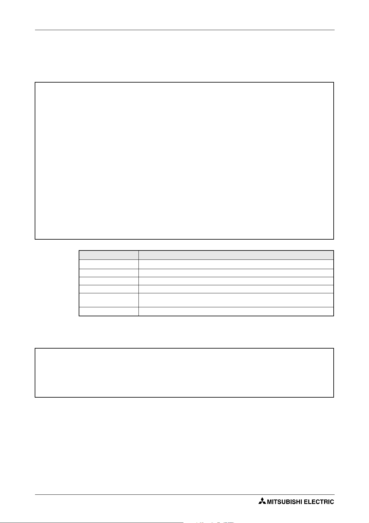
Product checking and part identification Inverter type
Symbol Voltage C l a s s
D720S Single-phase 230V
D740 Three-phase 400V class
Symbol Type N umb er
008
to
160
3-digit display
Symbol
Control Circuit Terminal
Specification
SC
Source-logic safety stop
function model
1 Product checking and part identification
Unpack the inverter and check the capacity plate on the front cover and the rating plate on the
inverter side face to ensure that the product agrees with your order and the inverter is intact.
1.1 Inverter type
FR - D740 - 036 SC - EC
I002080E
Fig. 1-1: Inverter type FR-D700 SC EC
FR-D700 SC EC 1 - 1
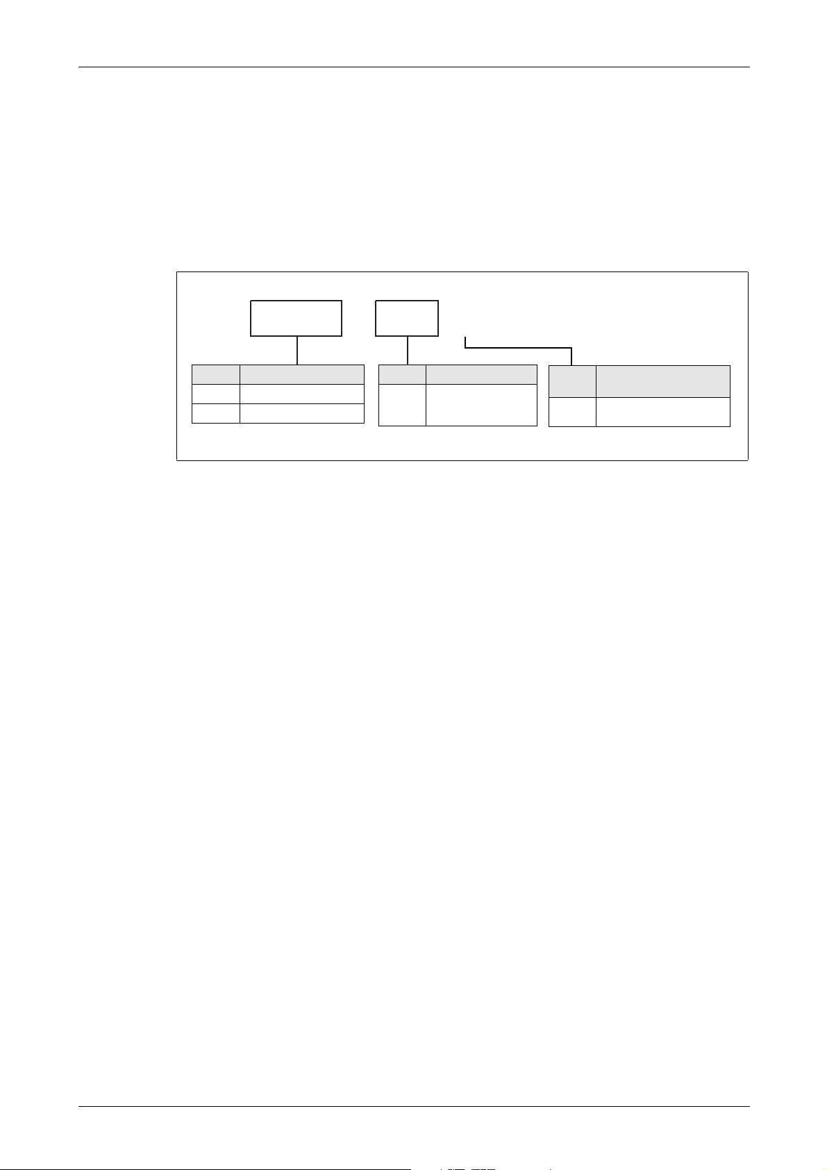
Description of the case Product checking and part identification
Capacity plate
Front cover
Inverter type
Inverter type
Serial number
PU connector
(refer to section 3.5)
Rating plate
Comb shaped
wiring cover
(refer to section 2.2)
Control circuit terminal
block
(refer to section 3.4)
Main circuit
terminal block
(
refer to section
3.3)
Voltage/current input switch
(refer to section 3.4)
Cooling fan
(refer to section 8.1.7)
Operation panel
(refer to section 4.3)
Changing the control
logic jumper connector
(refer to section 3.4.3)
Serial number
Input rating
Output rating
FR-D740-036SC-EC
FR-D740-036SC-EC
1.2 Description of the case
NOTE For removal and reinstallation of covers, refer to section 2.1.
1 - 2
Fig. 1-2: Appearance and structure
I002181E

Product checking and part identification Description of the case
1.2.1 Accessory
Fan cover fixing screws
Capacity Screw Size [mm] Number
FR-D720S-070SC and 100SC M3 × 35 1
FR-D740-036SC to 080SC M3 × 35 1
FR-D740-120SC and 160SC M3 × 35 2
Tab. 1-1: Fan cover fixing screws
NOTES
Inverters FR-D720S-008SC to 042SC and FR-D740-022SC or less are not provided with the
cooling fan. Therefore the fan cover fixing screws are not delivered with these models.
For removal and reinstallation of the cooling fans, refer to section 8.1.7.
FR-D700 SC EC 1 - 3

Description of the case Product checking and part identification
1 - 4
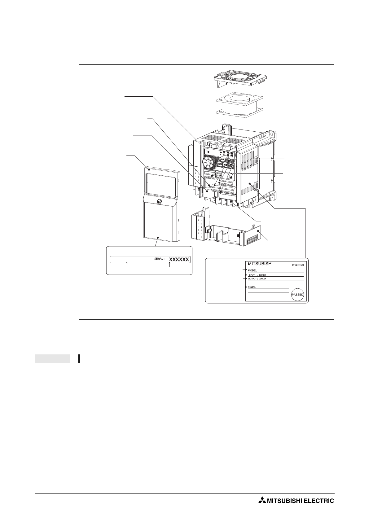
Installation Removal and reinstallation of the front cover
Example: FR-D740-036SC
Installation screw
Example: FR-D740-036SC
Installation screw
2 Installation
2.1 Removal and reinstallation of the front cover
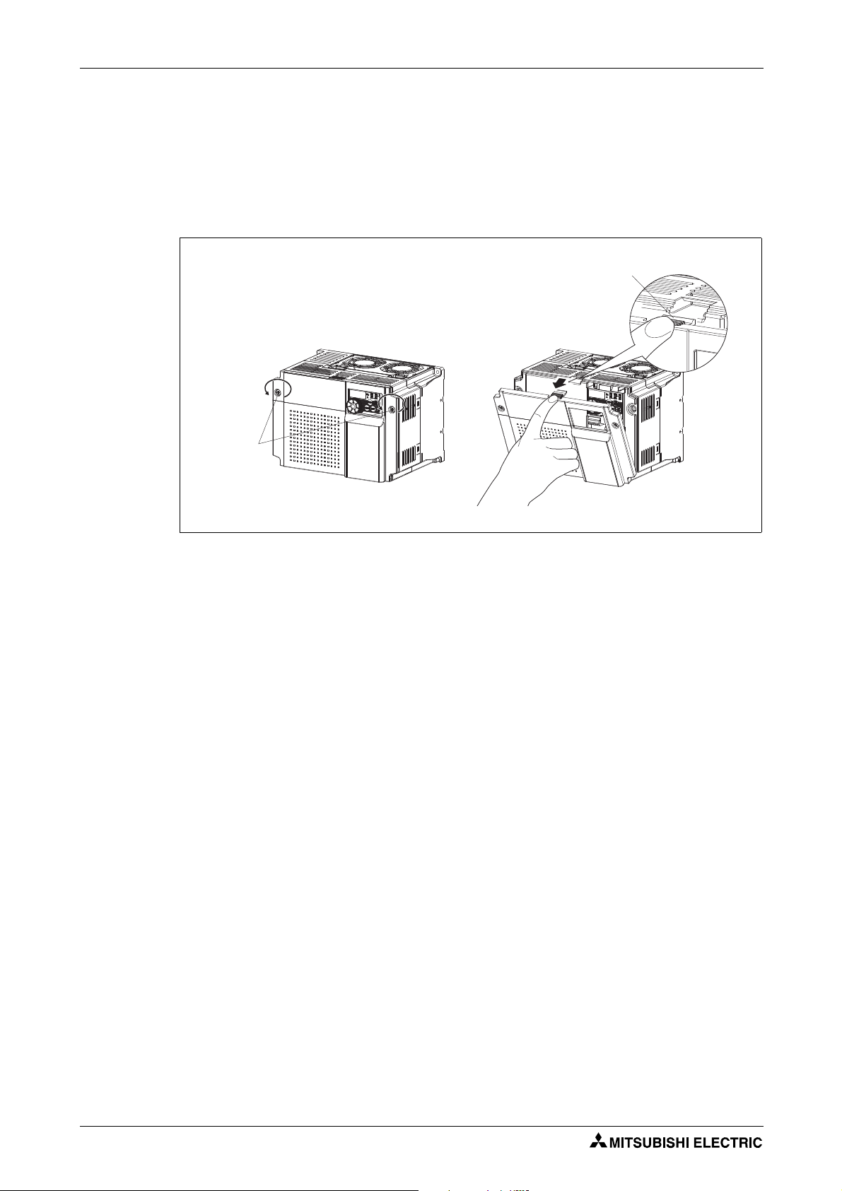
2.1.1 FR-D720S-008SC to 100SC and FR-D740-012SC to 080SC
Removal of the front cover
Loosen the installation screw of the front cover. (This screw cannot be removed.)
Remove the front cover by pulling it like the direction of arrow.
I001967E
Fig. 2-1: Removal of the front cover
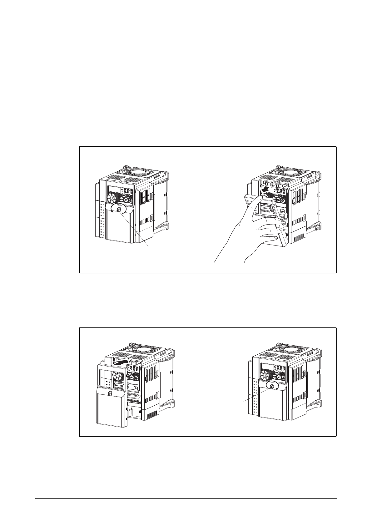
Reinstallation
To reinstall, match the cover to the inverter front and install it straight.
Tighten the installation screw.
I001968E
Fig. 2-2: Reinstallation of the front cover
FR-D700 SC EC 2 - 1
Removal and reinstallation of the front cover Installation
Front
cover 1
Front
cover 2
Installation
screws
Installation hook
Example: FR-D740-160SC
2.1.2 FR-D740-120SC and FR-D740-160SC
Removal of the front cover
Loosen the installation screws of the front cover. (The screws cannot be removed.)
Remove the front cover by pulling it like the direction of arrow with holding the installation
hook on the front cover.
I001969E
Fig. 2-3: Removal of the front cover
2 - 2

Installation Removal and reinstallation of the front cover
Installation
screws
Fixed hook
Socket of the inverter
Example: FR-D740-160SC
Reinstallation of the front cover
Insert the two fixed hooks on the lower side of the front cover into the sockets of the inverter.
Then press the cover against the device until it correctly locks on.
Tighten the installation screws.
NOTES
I001970E
Fig. 2-4: Reinstallation of the front cover
Fully make sure that the front cover has been reinstalled securely. Always tighten the installation screws of the front cover.
The same serial number is printed on the capacity plate of the front cover and the rating
plate of the inverter. Before reinstalling the front cover, check the serial numbers to ensure
that the cover removed is reinstalled to the inverter from where it was removed.
FR-D700 SC EC 2 - 3
Removal and reinstallation of the wiring cover Installation
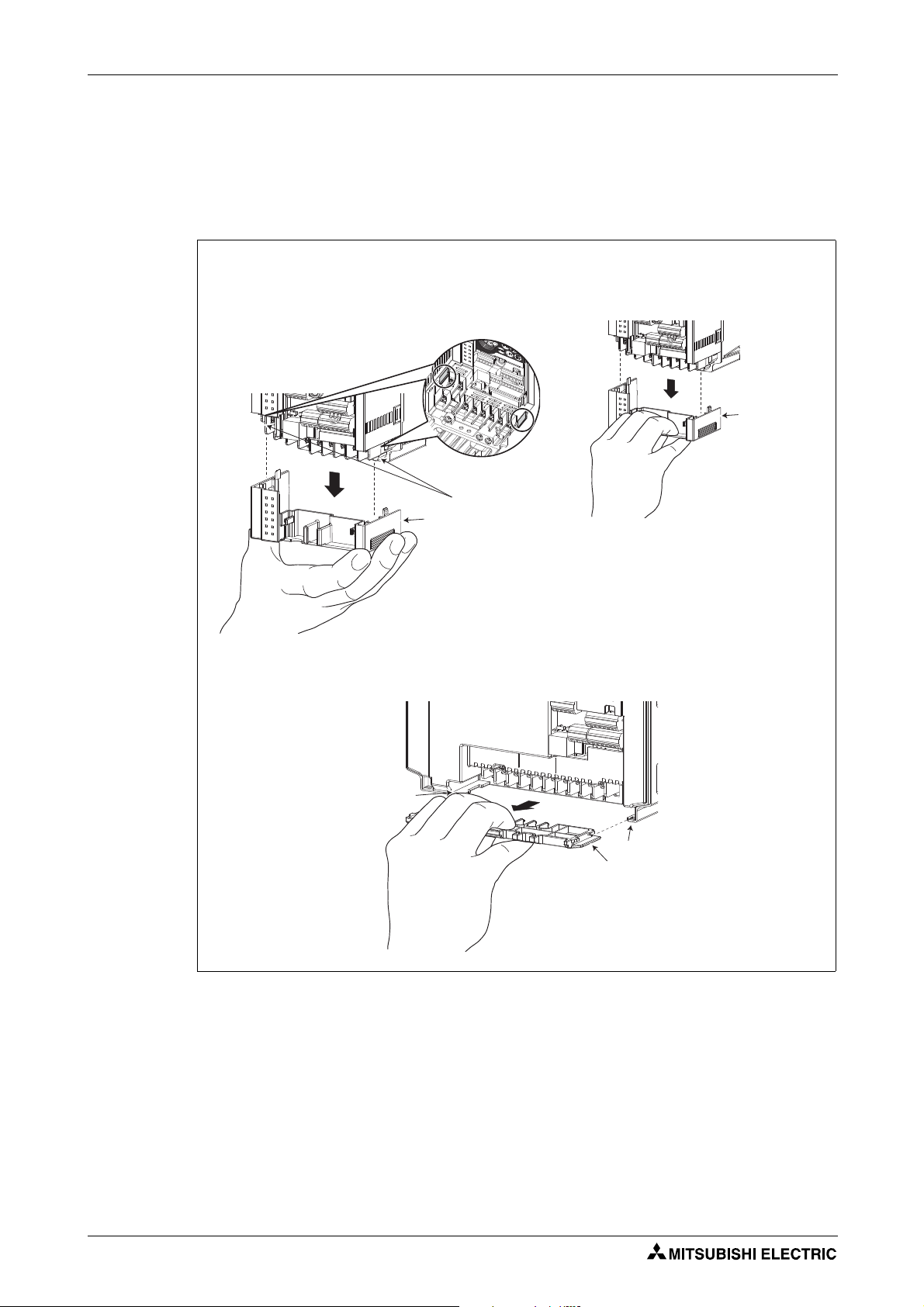
Inverter FR-D720S-008SC to 100SC and FR-D740-012SC to 080SC
Guides
Wiring cover
Inverter FR-D740-120SC and 160SC
Guide
Wiring cover
Guide
Hold the side of the wiring cover, and pull it
downward for removal.
Alternatively pull the wiring cover downward by
holding a frontal part of the wiring cover.
The cover can be removed easily by pulling it toward you.
2.2 Removal and reinstallation of the wiring cover
The cover can be removed easily by pulling it downward (FR-D720S-008SC to 100SC and
FR-D740-012SC to 080SC) or toward you (FR-D740-120SC and 160SC).
To reinstall, fit the cover to the inverter along the guides.
Fig. 2-5: Examples for removing the wiring cover
I002071E
2 - 4
Installation Mounting
Front cover
Wiring cover
Front cover
Wiring cover
FR-D720S-008SC to 042SC FR-D720S-070SC and 100SC,
FR-D740-012SC to 160SC
R
e
f
e
r
t
o
Fi
g
.
2
-
9
f
o
r
t
h
e
c
l
e
a
r
a
n
c
e
s
Ver ti cal
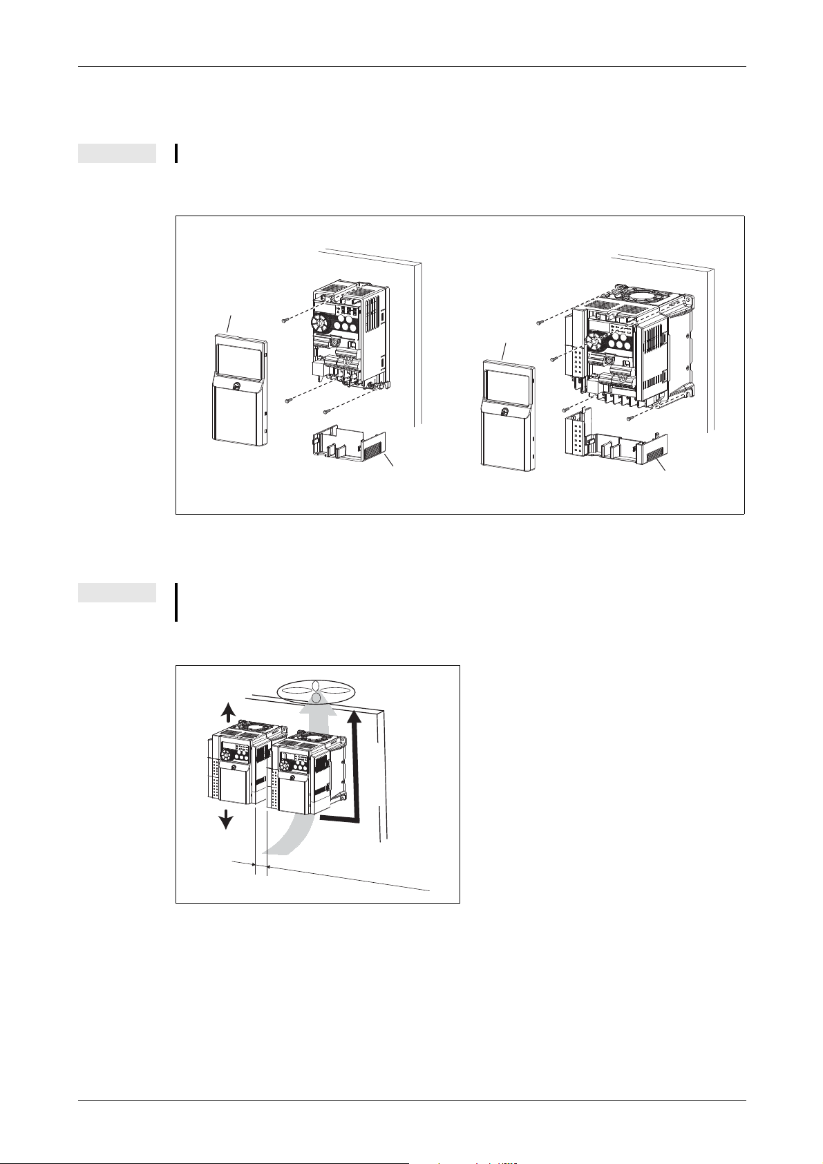
2.3 Mounting
NOTE Install the inverter vertically. Do not mount it horizontally or any other way.
Remove the front cover and wiring cover to fix the inverter to the surface.
Fig. 2-6: Installation on the panel
NOTE
When encasing multiple inverters, install them in parallel as a cooling measure. Leave
enough clearances around the inverter (refer to page 2-11).
Fig. 2-7:
Good heat dissipation is achieved through the
vertical alignment of the frequency inverter,
the side-by-side mounting and maintenance of
minimum clearances.
I002030E
I001973E
FR-D700 SC EC 2 - 5

Mounting Installation
Direct sunlight Vibration (≥ 5,9 m/s²) High temperature, high humidity Horizontal placement
(When mounted
inside enclosure)
Transportation by holding
the front cover or dial
Oil mist, flammable gas,
corrosive gas, fluff, dust, etc.
Mounting to
combustible material
The inverter consists of precision mechanical and electronic parts. Never install or handle it in
any of the following conditions as doing so could cause an operation fault or failure.
I001974E
Fig. 2-8: Conditions, that could cause an operation fault or failure
2 - 6
 Loading...