

Mitsubishi FR-D720-1.5K, FR-D720-0.1K, FR-D720-0.75K, FR-D720-0.2K, FR-D720-2.2K Instruction Manual
...
INVERTER
FR-D700
INSTRUCTION MANUAL (BASIC)
FR-D720-0.1K to 15K
FR-D740-0.4K to 15K
FR-D720S-0.1K to 2.2K
FR-D710W-0.1K to 0.75K
Thank you for choosing this Mitsubishi Inverter.
This Instruc tion Manual (Basic) is intended for users who "just want to run the inverter".
If you are going to utilize functions and performance, refer to the Instruction Manual (Applied) [IB-0600366ENG]. The
Instruction Manual (Applied) is separately available from where you purchased the inverter or your Mitsubishi sales
representa tive.
CONTENTS
PRODUCT CHECKING AND PARTS IDENTIFICATION ............................. 1
1
INSTALLATION AND WIRING ..................................................................... 2
2
2.1 Peripheral devices..................................................................................................... 3
2.2 Removal and reinstallation of the cover.................................................................... 4
2.3 Installation of the inverter and instructions ............................................................... 7
2.4 Wiring ........................................................................................................................ 9
2.5 When using the brake resistor (MRS type, MYS type, FR-ABR) ...........................26
2.6 Power-OFF and magnetic contactor (MC).............................................................. 27
2.7 Precautions for use of the inverter .......................................................................... 28
2.8 Failsafe of the system which uses the inverter ....................................................... 30
DRIVE THE MOTOR ................................................................................... 31
3
3.1 Step of operation..................................................................................................... 31
3.2 Operation panel....................................................................................................... 32
3.3 Before operation...................................................................................................... 40
3.4 Start/stop from the operation panel (PU operation)................................................ 54
3.5 Make a start and stop with terminals (External operation) ..................................... 62
3.6 Parameter list .......................................................................................................... 72
TROUBLESHOOTING ................................................................................ 96
4
4.1 Reset method of protective function ....................................................................... 96
4.2 List of fault or alarm indications .............................................................................. 97
4.3 Causes and corrective actions................................................................................ 98
4.4 Correspondences between digital and actual characters..................................... 107
4.5 Check and clear of the faults history..................................................................... 108
4.6 Check first when you have a trouble..................................................................... 110
PRECAUTIONS FOR MAINTENANCE AND INSPECTION..................... 117
5
5.1 Inspection items .................................................................................................... 117
SPECIFICATIONS..................................................................................... 125
6
6.1 Rating .................................................................................................................... 125
6.2 Common specifications......................................................................................... 127
6.3 Outline dimension drawings.................................................................................. 128
APPENDIX................................................................................................. 131
700
1
2
3
4
5
6
This Instruction Manual (Basic) provides handling information and precautions for use of the equipment.
Please forward this Instruction Manual (Basic) to the end user.
This section is specifically about safety matters
Do not attempt to install, operate, maintain or inspect the
inverter until you have read through the Instruction Manual
(Basic) and appended documents carefully and can use the
equipment correctly. Do not use this product until you have
a full knowledge of the equipment, safety in formation and
instructions.
In this Instruction Manu al (Basic), the safety in struction
levels are classified into "WARNING" and "CAUTION" .
WARNING
CAUTION
CAUTION
The level may even lead to a serious
consequence according to conditions. Both instruction
levels must be followe d because these are imp ortant to
personal safety.
Incorrect handling may cause
hazardous conditions, resulting in
death or severe injur y.
Incorrect handling may cause
hazardous conditions, resulting in
medium or slig ht injur y, or may cau se
only material damage.
1. Electric Shock Prevention
WARNING
z While power is ON or when the inverter is running, do not
open the front cover. Otherwise you may g et an electric
shock.
z Do not run the inverter with the front cover or wiring cover
removed. Otherwis e you may acces s the exposed highvoltage terminals or the charging part of the circuitry and
get an electric shock.
z Even if power is OFF, do not remove the front cover
except for wirin g or periodic in spection. You may access
the charged inver ter circuits and get an el ectric shock.
z Before wiring or insp ection, power must be switched OFF.
To confirm that, LED indication of the operation panel
must be checked. (It m ust be OFF.) Any person who is
involved in wiring o r inspection shall wa it for at least 10
minutes after the power supply has been switched OFF
and check that there are n o residual voltage using a teste r
or the like. The capacitor is charg ed with high vol tage for
some time after power OFF, and it is dangerous.
z This inverter must be earthed (grounded). Earthing
(grounding) must conform to the requirements of national
and local safety regulations an d electrical code (NEC
section 250, IEC 536 class 1 and other applicable
standards).
A neutral-point earthed (grounded) power supply for 400V
class inverter in comp liance with EN standard m ust be
used.
z Any person who is involved in wiring or inspection of this
equipment shall be fu lly competent to do the work.
z The inverter must be installed before wiring. Otherwise
you may get an electric shock or be injured.
z Setting dial and key operations must be performed with
dry hands to prevent an electric shock. Ot herwise you
may get an electric s hock.
z Do not subject the c ables to scratches, excessive stress,
heavy loads or pinching. Otherwise you may get an
electric shock.
z Do not change the cooling fan while power is ON. It is
dangerous to change the cooling fan while power is ON.
z Do not touch the printed circuit board with wet hands.
Otherwise you may g et an electric shock.
z When measuring t he main circuit capaci tor capacity, the
DC voltage is applied to t he motor for 1s at powering OFF.
Never touch the motor terminal, etc. right after powering
OFF to prevent an e lectric shock.
2. Fire Prevention
CAUTION
z Inverter must be installed on a nonflammable wall without
holes (so that nobody touches the inverter heatsink on the
rear side, etc.). M ounting it to or near flammable mat erial
can cause a fire.
z If the inverter h as become faulty, the inverte r power must
be switched OFF. A continuous flow of large current could
cause a fire.
z
When using a brake resistor, a sequence that will turn OFF
power when a fault s ignal is output mu st be configured.
Otherwise the brake resistor may excessively overheat due
to damage of the brake transistor and such, causing a fire.
z Do not connect a resi stor directly to the DC t erminals P/+
and N/-. Doing so could cause a fire.
A-1
3.Injury Prevention
CAUTION
z The voltage applied to each te rminal must be the ones
specified in the I nstruction Manual. O therwise burst,
damage, etc. may occur.
z The cables must be connected to the cor rect terminals.
Otherwise burst, damage, etc. may occur.
z Polarity must be co rrect. Otherwise b urst, damage, etc.
may occur.
z While power is ON or for some time after power-OFF, do
not touch the inverter since the inverter will be extremely
hot. Doing so can cause burns.
4. Additional Instructions
Also the following points must be noted to prevent an
accidental failure, injury, electric shoc k, etc.
(1) Transportation and Mounting
CAUTION
z The product must be transported in correct method that
corresponds to the weight. Failure to do so may lead to
injuries.
z Do not stack the boxes containing inv erters higher than
the number recommended.
z The product must be installed to the position where
withstands the weight of the product according to the
information in the In struction Manual.
z Do not install or operate the inverter if it is damaged or
has parts missing.
z When carrying the inverter, do not hold it by the front
cover or setting dial; it may fall off or fail.
z Do not stand or rest heavy objects on the product.
z The inverter mounting orientation must be correct.
z Foreign conductive bodies must be prevented to enter the
inverter. That includes screws and m etal fragments or
other flammable substance such as oil.
z As the inverter is a precision instrument, do not drop or
subject it to impact.
z The inverter must be used under the following
environment: Otherwise the inverter may be damaged.
Surrounding
air
temperature
Ambient
humidity
Storage
temperature
Atmosphere
Environment
Altitude/
vibration
∗1 Temperature app licable for a short ti me, e.g. in transit.
-10°C to +50°C (non -freezing)
(-10°C to +40°C for totally-enclosed structure
feature)
90%RH or less (non-condensing)
-20°C to +65°C *1
Indoors (free from corrosive gas, flammable gas,
oil mist, dust and di rt)
Maximum 1,000m above sea level.
2
or less at 10 to 55Hz (directions of X, Y, Z
5.9m/s
axes)
(2) Wiring
CAUTION
z Do not install a power fac tor correction capacitor or surge
suppressor/capacitor type filter on the inverter output
side. These devices on the inverter output side may be
overheated or burn out.
z The connection orientation of the output cables U, V, W to
the motor affects th e rotation direction of the motor.
(3) Trial run
CAUTION
z Before starting operation, each parameter must be
confirmed and adjusted. A failure to do so may cause
some machines to ma ke unexpected motions.
(4) Usage
WARNING
z Any person must s tay away from the equip ment when the
retry function is set as it will restart suddenly after trip.
z Since pressing key may not stop output dependi ng
on the function setting status, separate circuit and switch
that make an em ergency stop (power OFF, mechanical
brake operation for em ergency stop, etc.) must be
provided.
z OFF status of the start signal must be confirmed before
resetting the inverte r fault. Resetting inverte r alarm with
the start signal ON restarts the motor suddenly.
z The inverter must b e used for three- phase induction
motors.
Connection of any other electrical equipment to the
inverter output may damage the equipment.
z Do not modify the equipment.
z Do not perform parts removal which is not instructed in
this manual. Doing so may lead to fault or damage of the
product.
CAUTION
z The electronic thermal relay function does not guarantee
protection of the motor from overheating. It is
recommended to in stall both an external therm al and PTC
thermistor for over heat protection.
z Do not use a magnetic contactor on the inverter input for
frequent starting/stopping of the inverter. Otherwise, the
life of the invert er decreases.
z The effect of elect romagnetic interf erence must be
reduced by using an EMC filter or by other means.
Otherwise nearby electronic equipment may be affected.
z Appropriate measures must be taken to suppress
harmonics. Otherwise power supply harmonics from the
inverter may heat/d amage the power fac tor correction
capacitor and generator.
z When driving a 400V class mo tor by the inverter, the
motor must be an insulation-enhanced motor or measures
must be taken to suppress surge voltage. Surge voltage
attributable to the wiring constants may occur at the
motor terminals, deteriorating the insulation of the motor.
z When parameter clear or all parameter clear i s performed,
the required paramet ers must be set ag ain before starting
operations becaus e all parameters return t o the initial
value.
z The inverter can be easily set for high-speed operation.
Before changing its setting, the performances of the
motor and machine must be fully examined.
z Stop status cannot be hold by the inverter's brake
function. In addition to the inverter's brake function, a
holding device must be installed to ensure safety.
z Before running an inverter which had been stored for a
long period, inspection and test operation must be
performed.
z For prevention of damage due to static electricity, nearby
metal must be touched before touching this product to
eliminate static electricity from your body.
A-2
(5) Emergency stop
CAUTION
z A safety backup such as an em ergency brake must b e
provided to prevent hazardous condition to the machine
and equipment in ca se of inverter failure.
z When the breaker on the inverter input side trips, the
wiring must be checked for fault (short circuit), and
internal parts of the inverter for a damage, etc. Th e cause
of the trip must be identified and removed before turning
ON the power of the breaker.
z When any protective function is activated, appropriate
corrective action must be taken, and the inverter must be
reset before resuming operation.
(6) Maintenance, inspection and parts replacement
CAUTION
z Do not carry out a megger (insulation resistance) test on
the control circuit of the inverter. It will cause a fai lure.
(7) Disposal
CAUTION
z The inverter must be treated as industrial waste.
General instruction
Many of the diagrams and dr awings in this Instruction
Manual (Basic) show the inverter without a cover or partially
open for explanation. Never operate the inverter in this
manner. The cover must be alw ays reinstalled and the
instruction in this Instruct ion Manual (Basic) must be
followed when operating the inverter.
A-3

CONTENTS
1 PRODUCT CHECKING AND PARTS IDENTIFICATION 1
2 INSTALLATION AND WIRING 2
2.1 Peripheral devices ...................................................................................................3
2.2 Removal and reinstallation of the cover ............................................................... 4
2.2.1 Front cover..................................................................................................................................... 4
2.2.2 Wiring cover................................................................................................................................... 6
2.3 Installation of the inverter and instructions .........................................................7
2.4 Wiring ....................................................................................................................... 9
2.4.1 Terminal connection diagram ........................................................................................................ 9
2.4.2 Specification of main circuit terminal ........................................................................................... 10
2.4.3 Terminal arrangement of the main circuit terminal, power supply and the motor wiring.............. 10
2.4.4 Control circuit terminal ................................................................................................................. 15
2.4.5 Changing the control logic ........................................................................................................... 17
2.4.6 Wiring of control circuit ................................................................................................................ 19
2.4.7 Safety stop function ..................................................................................................................... 22
2.4.8 Connection to the PU connector.................................................................................................. 24
2.5 When using the brake resistor (MRS type, MYS type, FR-ABR) .......................26
2.6 Power-OFF and magnetic contactor (MC) ...........................................................27
2.7 Precautions for use of the inverter ......................................................................28
2.8 Failsafe of the system which uses the inverter .................................................. 30
3 DRIVE THE MOTOR 31
3.1 Step of operation ...................................................................................................31
3.2 Operation panel ..................................................................................................... 32
3.2.1 Names and functions of the operation panel ............................................................................... 32
3.2.2 Basic operation (factory setting) .................................................................................................. 33
3.2.3 Easy operation mode setting (easy setting mode)....................................................................... 34
3.2.4 Operation lock (Press [MODE] for a while (2s))........................................................................... 35
3.2.5 Monitoring of output current and output voltage .......................................................................... 36
3.2.6 First priority monitor ..................................................................................................................... 36
3.2.7 Setting dial push .......................................................................................................................... 36
I

3.2.8 Changing the parameter setting value......................................................................................... 37
3.2.9 Parameter clear/all parameter clear ............................................................................................ 38
3.2.10 Initial value change list ................................................................................................................ 39
3.3 Before operation ................................................................................................... 40
3.3.1 Simple mode parameter list......................................................................................................... 40
3.3.2 Overheat protection of the motor by the inverter (Pr. 9) .............................................................. 41
3.3.3 When the rated motor frequency is 50Hz (Pr. 3) ........................................................................ 43
3.3.4 Increasing the starting torque (Pr. 0) .......................................................................................... 44
3.3.5 Setting the maximum and minimum output frequency (Pr. 1, Pr. 2)............................................ 45
3.3.6 Changing acceleration and deceleration time of the motor (Pr. 7, Pr. 8)..................................... 46
3.3.7 Selection of the start command and frequency command locations (Pr. 79) .............................. 47
3.3.8 Acquiring large starting torque and low speed torque (General-purpose magnetic
flux vector control (Pr. 71, Pr. 80))............................................................................................... 48
3.3.9 Exhibiting the best performance for the motor (offline auto tuning)
(Pr. 71, Pr. 80, Pr. 82 to Pr. 84, Pr. 90, Pr. 96) ............................................................................ 50
3.4 Start/stop from the operation panel (PU operation) .......................................... 54
3.4.1 Setting the frequency by the operation panel.............................................................................. 54
3.4.2 Using the setting dial like a potentiometer to perform operation ................................................. 56
3.4.3 Setting the frequency by switches (three-speed setting) (Pr. 4 to Pr. 6) ..................................... 57
3.4.4 Setting the frequency by analog input (voltage input) ................................................................. 59
3.4.5 Setting the frequency by analog input (current input).................................................................. 60
3.5 Make a start and stop with terminals (External operation) ............................... 62
3.5.1 Setting the frequency by the operation panel (Pr. 79 = 3)............................................................ 62
3.5.2 Setting the frequency by switches (three-speed setting) (Pr. 4 to Pr. 6) ..................................... 64
3.5.3 Setting the frequency by analog input (voltage input) ................................................................. 66
3.5.4 Changing the output frequency (60Hz, initial value) at the maximum voltage input
(5V, initial value) .......................................................................................................................... 68
3.5.5 Setting the frequency by analog input (current input).................................................................. 69
3.5.6 Changing the output frequency (60Hz, initial value) at the maximum current input
(at 20mA, initial value) ................................................................................................................. 71
3.6 Parameter list ........................................................................................................ 72
3.6.1 List of parameters classified by the purpose ............................................................................... 72
3.6.2 Displaying the extended parameters........................................................................................... 74
3.6.3 Parameter list .............................................................................................................................. 75
CONTENTS
4 TROUBLESHOOTING 96
4.1 Reset method of protective function .................................................................. 96
II

4.2 List of fault or alarm indications ..........................................................................97
4.3 Causes and corrective actions ............................................................................98
4.4 Correspondences between digital and actual characters ............................... 107
4.5 Check and clear of the faults history ................................................................ 108
4.6 Check first when you have a trouble ................................................................. 110
4.6.1 Motor does not start................................................................................................................... 110
4.6.2 Motor or machine is making abnormal acoustic noise ............................................................... 112
4.6.3 Inverter generates abnormal noise............................................................................................ 113
4.6.4 Motor generates heat abnormally.............................................................................................. 113
4.6.5 Motor rotates in the opposite direction....................................................................................... 113
4.6.6 Speed greatly differs from the setting........................................................................................ 113
4.6.7 Acceleration/deceleration is not smooth .................................................................................... 114
4.6.8 Speed varies during operation................................................................................................... 114
4.6.9 Operation mode is not changed properly................................................................................... 115
4.6.10 Operation panel display is not operating ................................................................................... 115
4.6.11 Motor current is too large........................................................................................................... 115
4.6.12 Speed does not accelerate........................................................................................................ 116
4.6.13 Unable to write parameter setting .............................................................................................. 116
5 PRECAUTIONS FOR MAINTENANCE AND INSPECTION 117
5.1 Inspection items .................................................................................................. 117
5.1.1 Daily inspection.......................................................................................................................... 117
5.1.2 Periodic inspection..................................................................................................................... 117
5.1.3 Daily and periodic inspection ..................................................................................................... 118
5.1.4 Display of the life of the inverter parts ....................................................................................... 119
5.1.5 Cleaning..................................................................................................................................... 121
5.1.6 Replacement of parts................................................................................................................. 121
6 SPECIFICATIONS 125
6.1 Rating ...................................................................................................................125
6.2 Common specifications ......................................................................................127
6.3 Outline dimension drawings .............................................................................. 128
III
APPENDIX 131
V/F
GP
MFVC
Appendix1 For customers replacing the conventional model with this inverter ... 131
appendix 1-1 Replacement of the FR-S500 series ............................................................................. 131
Appendix 2 Instructions for Compliance with the EU Directives ............................ 133
Appendix 3 Instructions for UL and cUL.................................................................... 136
<Abbreviations and terms>
PU: Operation pan el and parameter unit (FR-PU04/FR-PU07 )
Inverter: Mitsubishi inverter FR-D700 series
D700: Mitsubishi inverter FR-D700 series
FR-
Pr.: Parameter number
PU operation: Operation usin g the PU (oper ation panel/FR -PU04/FR-PU07)
External operation: Operation using the control circuit signals
Combined operation: Operation using both the PU (operation panel/FR-PU04/FR-PU07) and External operation
Operation panel for E500, PA02: FR-E500 series operation panel
Mitsubishi standard motor: SF-JR
Mitsubishi constant-torque motor: SF-HRCA
<Trademarks>
Company and product names herein are the trademarks and registered trademarks of their respective owners.
<Marks>
V/F
V/F
: Indicates functions available during V/F control
GP
MFVC
GP
MFVC
: Indicates functions available during General-purpose magnetic flux vector control
REMARKS :Additional helpful contents and relations with other functions are stated
NOTE :Contents requiring caution or cases when set functions are not activated are stated.
POINT :Useful contents and points are stated.
CONTENTS
IV

MEMO
V

1 PRODUCT CHECKING AND PARTS IDENTIFICATION
Unpack the inverter and check the capacity plate on the front cover and the rating plate on the inverter side face to ensure that
the product agrees with your order and the inverter is intact.
zInverter model
--
FR
D740 1.5
K
Symbol Voltage class
Three-phase 200V class
D720
Three-phase 400V class
D740
Single-phase 200V class
D720S
Single-phase 100V class
D710W
Operation panel
(Refer to page 32)
Voltage/current input switch
(Refer to page 15)
PU connector
(Refer to page 16)
Front cover
(Refer to page 4)
Capacity plate
1.5K
Inverter model
Represents the
inverter capacity [kW]
Serial number
Rating plate
Inverter model
Input rating
Output rating
Serial number
Control circuit terminal
block
(Refer to page 15)
Control logic switchover
jumper connector
(Refer to page 17)
Main circuit
terminal block
(Refer to page 10)
Combed shap ed
wiring cover
(Refer to page 6)
FR-D740-1.5K
1
• Accessory
· Fan cover fixing screws (M3 × 35mm)
These screws are necessary for compliance with the EU Directive.
Harmonic suppression guideline (when inverters are used in Japan)
All models of general -purpose inverters us ed by specific consume rs are covered by "Har monic suppression guideline for consume rs who
receive high voltage or spe cial high voltage". (For fu rther details, refer to Chapter 3 of the Instruction Manual (Applied).)
Capacity Number
1.5K to 3.7K 1
5.5K to 15K 2
(
Refer to page 133
)
PRODUCT CHECKING AND PARTS IDENTIFICATION
1
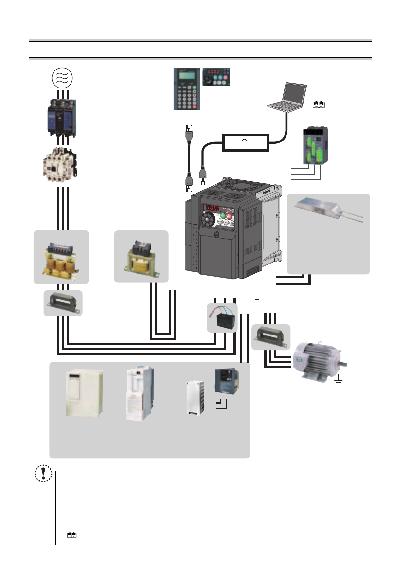
2 INSTALLATION AND WIRING
AC power supply
Use within the permissible power supply
specifications of the inverter. To ensure
safety, use a moulded case circuit breaker,
earth leakage circuit breaker or magnetic
contactor to switch power ON/OFF.
(Refer to page 125)
Moulded case circuit breaker
(MCCB) or earth leakage circuit
breaker (ELB), fuse
The breaker must be selected carefully
since an in-rush current flows in the
inverter at power on.
(Refer to page 3)
Magnetic contactor (MC)
Install the magnetic contactor to ensure
safety. Do not use this magnetic contactor
to start and stop the inverter. Doing so will
cause the inverter life to be shorten.
(Refer to page 3)
Reactor (FR-HAL, FR-HEL option)
Reactors (option) must be used when
power harmonics measures are taken,
the power factor is to be improved or the
inverter is installed near a large power
supply system (500kVA or more). The
inverter may be damaged if you do not
use reactors. Select the reactor according
to the model. Remove the jumpers across
AC reactor (FR-HAL)
* Filterpack (FR-BFP2), which contains DC reactor and EMC filter in one package, is also available.
terminals P/+ and P1 to connect the DC reactor.
Install an EMC filter (ferrite core)
to reduce the electromagnetic
noise generated from the
inverter. Effective in the range
from about 1MHz to 10MHz.
When more wires are passed
through, a more effective result
can be obtained. A wire should
be wound four turns or more.
High power factor
converter (FR-HC)
Power supply harmonics
can be greatly suppressed.
Install this as required.
DC reactor (FR-HEL) *
EMC filter (ferrite core) *
(FR-BSF01, FR-BLF)
Power regeneration
common converter
(FR-CV)
Great braking capability
is obtained.
Install this as required.
Parameter unit
(FR-PU07)
P/+
P1
Resistor unit (FR-BR)
Discharging resistor (GZG, GRZG)
The regenerative braking capability
of the inverter can be exhibited fully.
Install this as required.
NOTE
The life of the inverter is influenced by surrounding air temperature. The surrounding air temperature should be as low as
possible within the permissible range. This must be noted especially when the inverter is installed in an enclosure.
Wrong wiring might lead to damage of the inverter. The control signal lines must be kept fully away from the main
circuit to protect them f rom noise. (Refer to page 9)
Do not install a power factor correction capacitor, surge suppressor or EMC filter (capacitor) on the inverter output
side. This will cause the inverter to trip or the capacitor and surge suppressor to be damaged. If any of the above
devices are connected, immediate ly remove them.
Electromagnetic wave interference
The input/output (main circuit) of the inverter includes high frequency components, which may interfere with the
communication device s (such as AM radios) used ne ar the inverter. In this case, install the FR-BIF optional
(capacitor)
(for use in the input side only) or FR-BSF01 or FR-BLF
(
Refer to Chapter 3 of the Instructio n Manual (Applied)
Refer to the Instruction Manual of each option and peripheral devices for details of peripheral devices.
Enclosure surface operation
panel (FR-PA07)
By connecting the connection cable
(FR-CB2) to the PU connector,
operation can be performed from
FR-PU07, FR-PA07.
(Refer to page 24)
Inverter (FR-D700)
Brake unit
(FR-BU2)
R/L1 S/L2T/L3
P/+
PR
EMC filter
(capacitor) *
(FR-BIF)
Reduces the
radio noise.
).
RS-485 RS-232C
PR
P/+
RS-232C - RS-485 converter is
required when connecting to PC
with RS-232C interface.
( Refer to Chapter 4
of the Instruction Manual
(Applied))
Converter
S1
S2
SC
P/+
PR
EMC filter (ferrite core)
Earth (Ground)
UW
N/-
P/+
Devices connected to the output
Do not install a power factor correction capacitor,
surge suppressor or EMC filter (capacitor) on the output
side of the inverter. When installing a moulded case
circuit breaker on the output side of the inverter,
contact each manufacturer for selection of the
moulded case circuit breaker.
Earth (Ground)
To prevent an electric shock, always earth (ground)
the motor and inverter. For reduction of induction noise
from the power line of the inverter, it is recommended
to wire the earth (ground) cable by returning it to the
earth (ground) terminal of the inverter.
(FR-BSF01, FR-BLF)
Install an EMC filter (ferrite core)
to reduce the electromagnetic
V
noise generated from the inverter.
Effective in the range from about
1MHz to 10MHz. A wire should be
wound four turns at a maximum.
EMC filter (ferrite core)
Approved safety
relay module
Required for
compliance with
safety standard.
Brake resistor (FR-ABR,
MRS type, MYS type)
Braking capability can be
improved. (0.4K or more)
Always install a thermal relay
when using a br ake resistor
whose capacity is 11K or more.
(Refer to page 26)
to minimize interference.
Motor
Earth (Ground)
(Refer to page 7)
EMC filter
2
Peripheral devices
2.1 Peripheral devices
Check the inverter model of the inverter you purchased. Appropriate peripheral dev ices must be selected according to the capacity.
Refer to the following list and prepare appropriate peripheral devices:
Moulded Case Circuit Breaker
(MCCB) ∗1
(ELB) ∗2
Reactor connection Reactor connection
Inverter Model
Motor
Output
(kW)
or Earth Leakage Circuit Breaker
without with without with
FR-D720-0.1K 0.1 30A F 5A 30AF 5A S-N10 S-N10 0.4K ∗5 0.4K ∗5
FR-D720-0.2K 0.2 30A F 5A 30AF 5A S-N10 S-N10 0.4K ∗5 0.4K ∗5
FR-D720-0.4K 0.4 30A F 5A 30AF 5A S-N10 S-N10 0.4K 0.4K
FR-D720-0.75K 0.75 30AF 1 0A 30AF 5A S-N10 S-N10 0.75K 0.75K
FR-D720-1.5K 1.5 30AF 15A 30AF 10A S-N10 S-N10 1.5K 1.5K
FR-D720-2.2K 2.2 30AF 20A 30AF 15A S-N10 S-N10 2.2K 2.2K
FR-D720-3.7K 3.7 30AF 30A 30AF 30A S-N20, S-N21 S-N10 3.7K 3.7K
FR-D720-5.5K 5.5 50AF 50A 50AF 40A S-N20, S-N21 S-N20, S-N21 5.5K 5.5K
Three-Phase 200V
FR-D720-7.5K 7.5 100AF 60A 50AF 50A S-N25 S -N20, S-N21 7.5K 7.5K
FR-D720-11K 11 100AF 75A 100AF 75A S -N35 S-N35 11K 11K
FR-D720-15K 15 225AF 125A 100AF 100A S-N50 S-N50 15K 15K
FR-D740-0.4K 0.4 30A F 5A 30AF 5A S-N10 S-N10 H0.4K H0 .4K
FR-D740-0.75K 0.75 30AF 5A 30AF 5A S-N10 S-N10 H0.75K H0.75K
FR-D740-1.5K 1.5 30AF 10A 30AF 10A S-N10 S-N10 H1.5K H1 .5K
FR-D740-2.2K 2.2 30AF 15A 30AF 10A S-N10 S-N10 H2.2K H2 .2K
FR-D740-3.7K 3.7 30AF 20A 30AF 15A S-N10 S-N10 H3.7K H3 .7K
FR-D740-5.5K 5.5 30AF 30A 30AF 20A S-N20, S-N21 S-N11, S-N12 H5. 5K H5.5K
FR-D740-7.5K 7.5 30AF 30A 30AF 30A S-N20, S-N21 S-N20, S-N21 H7.5K H7.5K
Three-Phase 400V
FR-D740-11K 11 50AF 50A 50AF 40A S-N20, S-N21 S-N20, S-N21 H11K H11K
FR-D740-15K 15 100AF 60A 5 0AF 50A S-N25 S-N20, S-N21 H15K H15K
FR-D720S-0.1K 0.1 30A F 5A 30AF 5A S-N10 S-N10 0.4K ∗5 0.4K ∗5
FR-D720S-0.2K 0.2 30A F 5A 30AF 5A S-N10 S-N10 0.4K ∗5 0.4K ∗5
FR-D720S-0.4K 0.4 30AF 10A 30AF 10A S-N10 S-N10 0.75K ∗5 0.75K ∗5
FR-D720S-0.75K 0.75 30AF 15A 30AF 10A S-N10 S-N10 1.5K ∗5 1.5K ∗5
FR-D720S-1.5K 1.5 30AF 20A 30AF 20A S-N10 S-N10 2.2K ∗5 2.2K ∗5
FR-D720S-2.2K 2.2 50AF 40A 30AF 30A S-N20, S-N21 S-N10 3.7K ∗5 3.7K ∗5
Single-Phase 200V
FR-D710W-0.1K 0.1 30 AF 10A 30AF 5A S-N10 S-N10
FR-D710W-0.2K 0.2 30 AF 10A 30AF 10A S-N10 S-N10 1.5K ∗ 4, ∗5 — ∗6
FR-D710W-0.4K 0.4 30 AF 15A 30AF 15A S-N10 S-N10 2.2K ∗ 4, ∗5 — ∗6
FR-D710W-0.75K 0.75 30AF 3 0A 30AF 20A S-N10 S-N10 3.7K ∗4 , ∗5 — ∗6
Single-Phase 100V
∗1 Select an MCCB according to the power supply capacity.
Install one MCCB per inverter.
∗2 For the use in the United States or Canada, select a UL and cUL certified fuse with Class T fuse equivalent cut-off
speed or faster with the appropriate rating for branch circuit protection. Alternatively, select a UL489 molded case circuit breaker (MCCB). (Refer to page 136)
∗3 Magnetic contactor is selected based on the AC-1 class. The electrical durability of magnetic contactor is 500,000 times. When the magnetic contactor is
used for emergency stop during motor driving, the electrical durability is 25 times.
When using the MC for emergency stop during motor driving or using on the motor side during commercial-power supply operation, select the MC with cla ss
AC-3 rated current for the motor rated current.
∗4 When connecting a single-phase 100V power input model to a power transformer (50kVA or more), install an AC reactor (FR-HAL) so that the performance
is more reliable. ( Refer to Chapter 3 of the Instruction Manual (Applied))
∗5 The power factor may be slightly lower.
∗6 Single-phase 100V power input model is not compatible with DC reactor.
NOTE
y When the inverter capacity is larger than the motor capacity, select an MCCB and a magnetic contactor according to the inverter model
and cable and reactor according to the motor output.
y When the breaker on the inverter input side trips, check for the wiring fault (short circuit), damage to internal parts of the inverter, etc.
Identify the cause of the trip, then remove the cause and power ON the breaker.
Magnetic Contactor (MC)
∗3
Reactor
FR-HAL FR-H EL
0.75K
∗4, ∗5
— ∗6
MCCB INV
MCCB INV
IM
IM
2
INSTALLATION AND WIRING
3
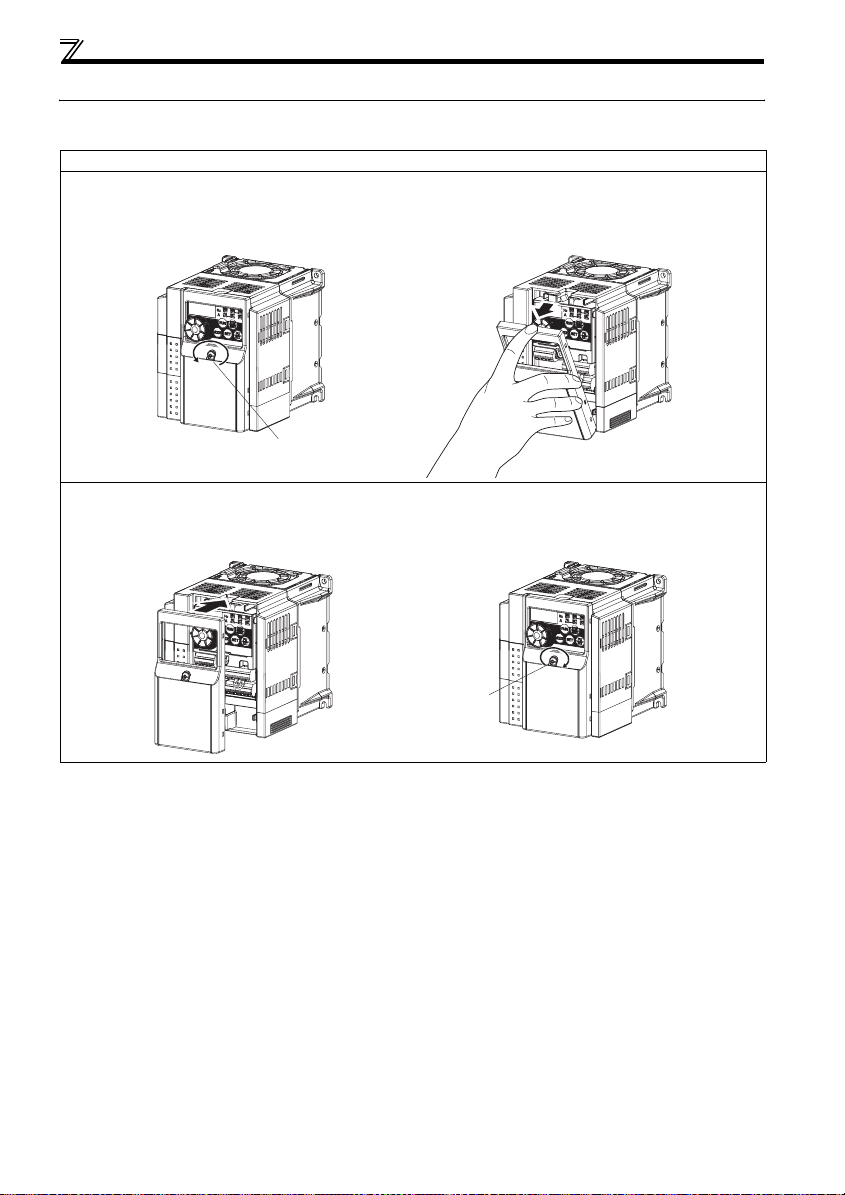
Removal and reinstallation of the cover
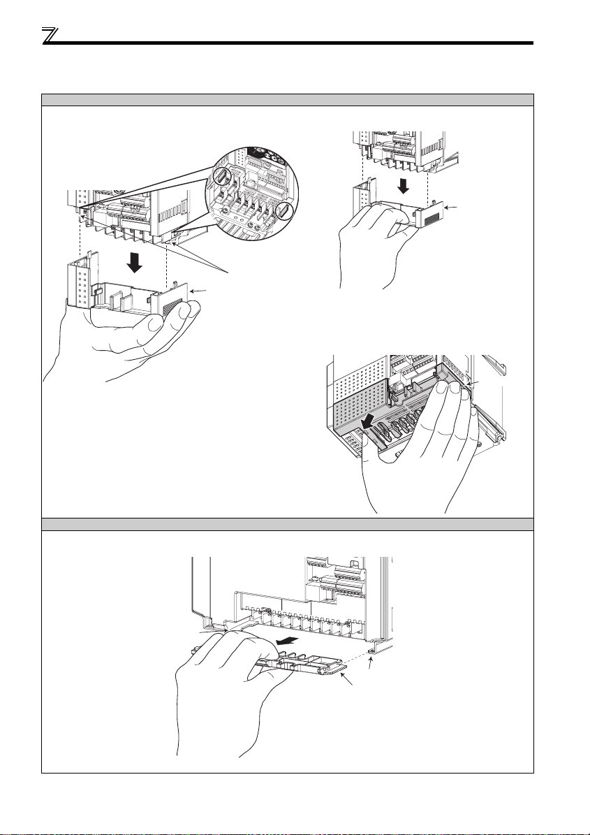
2.2 Removal and reinstallation of the cover
2.2.1 Front cover
3.7K or less
zRemoval (Example of FR-D740-1.5K)
1) Loosen the installation screws of the front cover. (The screws cannot be removed.)
2) Remove the front cover by pulling it like the direction of arrow.
1)
Installation screw
zReinstallation (Example of FR-D740-1.5K)
1) Place the front cover in front of the inverter, and install it straight.
2) Tighten the installation screws on the front cover.
1) 2)
2)
Installation screw
4
Removal and reinstallation of the cover
5.5K or more
zRemoval (Example of FR-D740-7.5K)
1) Loosen the installation screws of the front cover. (The screws cannot be removed.)
2) Remove the front cover by pulling it like the direction of arrow with holding the installation hook on the front cover.
Installation hook
1) 2)
Installation
screw
zReinstallation (Example of FR-D740-7.5K)
1) Insert the two fixed hooks on the lower side of the front cover into the sockets of the inverter.
2) Tighten the installation screws on the front cover.
1) 2)
Installation screw
Fixed hook
Socket of the inverter
NOTE
Fully make sure that th e front cover has bee n reinstalled securely.
The same serial num ber is printed on the capacity plate of th e front cover a nd the rating plate of the inverter. Since
these plates have the s ame serial numbers, a lways reinstall the remo ved cover onto the orig inal inverter.
2
INSTALLATION AND WIRING
5
Removal and reinstallation of the cover
r
r
r
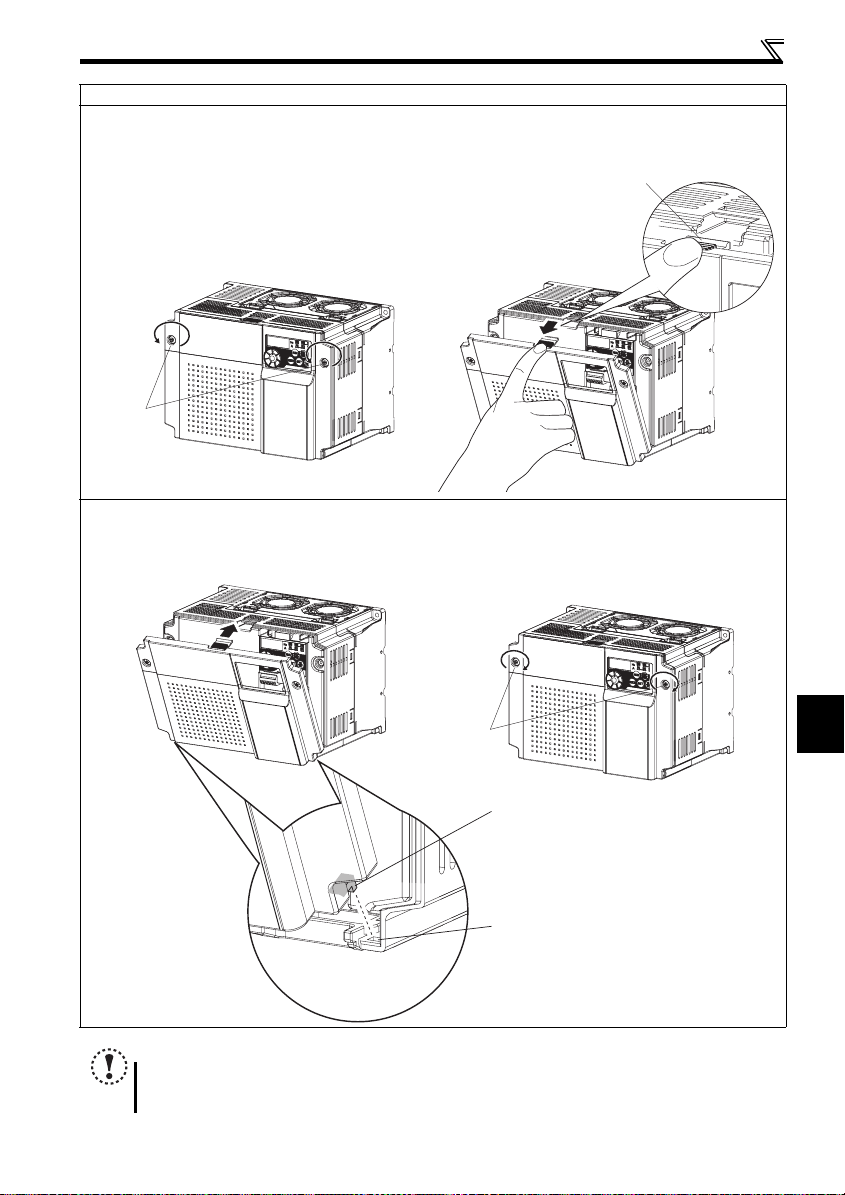
2.2.2 Wiring cover
zRemoval and reinstallation
3.7K or less
y Hold the side of the wiring cover, and pull it downward for
removal.
To reinstall, fit the cover to the inverter along the guides.
Guide
Wiring cover
y Also pull the wiring cover downward by holding a
frontal part of the wiring cover.
Wiring cove
Example of FR-D740 -1.5K
y See below diagram for wiring cover of FR-D720-3.7K.
Hold the dent of the wiring cover (marked with an
arrow) with thumb and the side with other fingers and
pull downward for removal.
Example of FR-D740-1.5K
5.5K or more
y The cover can be removed easily by pulling it toward you.
To reinstall, fit the cover to the inverter along the guides.
Guide
Example of FR-D740- 7.5K
Wiring cove
Guide
Wiring cove
6
Installation of the inverter and instructions
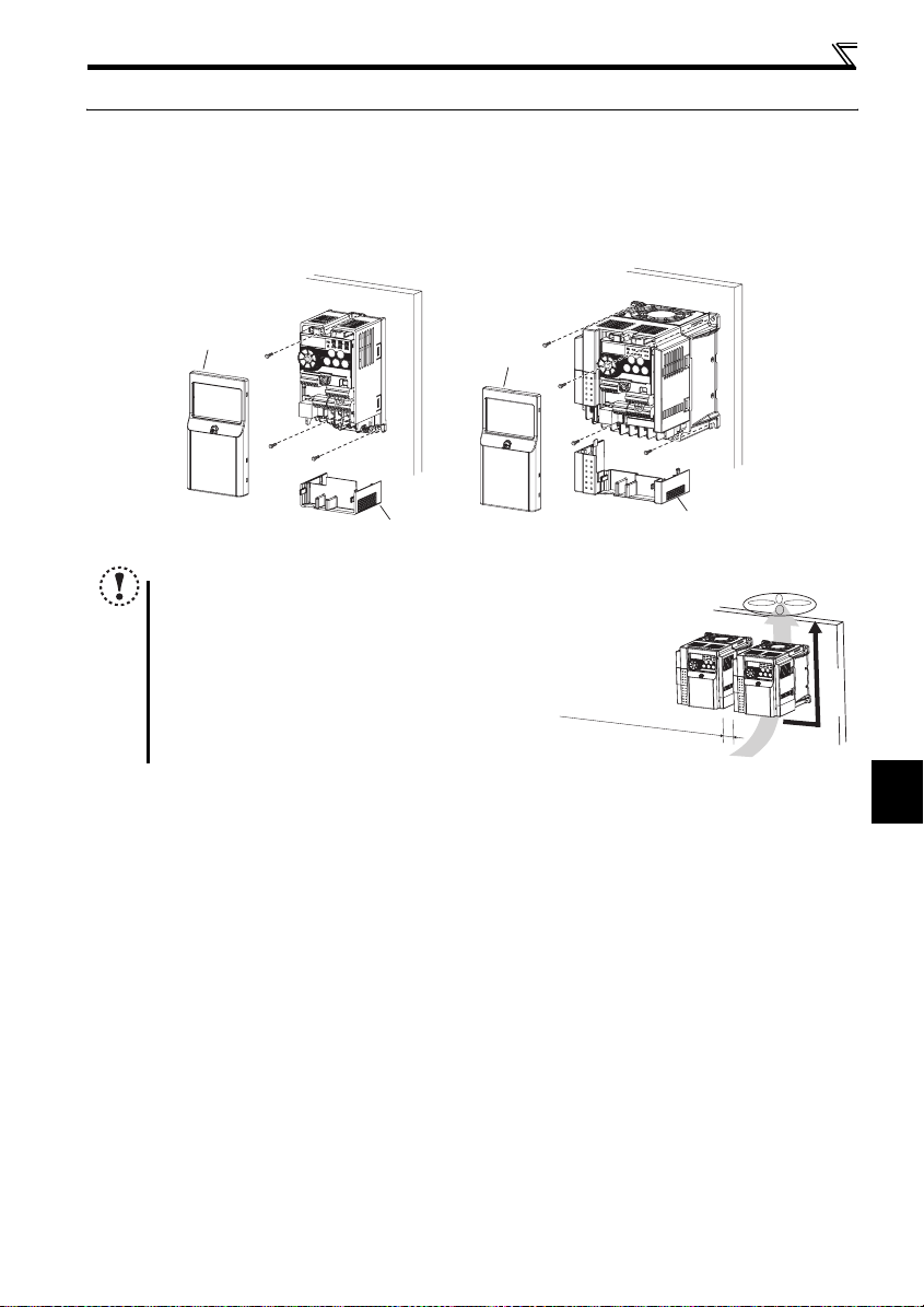
2.3 Installation of the inverter and instructions
Installation of the inverter
Enclosure surface mounting
Remove the front cover and wiring cover to fix the inverter to the surface.
FR-D720-0.1K to 0.75 K
FR-D720S-0.1K to 0.75K
FR-D710W-0.1K to 0 .4K
FR-D720-1.5K or more
FR-D740-0.4K or more
FR-D720S-1.5K, 2.2K
FR-D710W-0.75K
Front cover
Front cover
Wiring cover
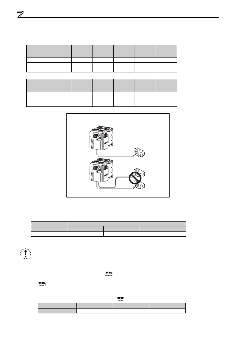
Note
When encasing multiple inv erters, install them in parallel as a
cooling measure.
Install the inverter vertical ly.
R
efer to the clea
ra
nces belo
Wiring cover
w
.
Vertical
2
INSTALLATION AND WIRING
7
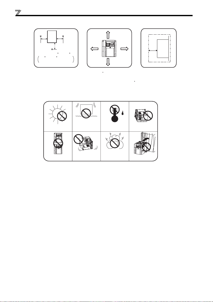
Installation of the inverter and instructions
Install the inverter under the following conditions.
Surrounding air temperature and humidity
Measurement
position
Inverter
5cm
5cm
Measurement
Temperature: -10 C to +50 C
-enclosed structure feature
Humidity: 90% RH maximum
Leave enough clearances and
take cooling measures.
The inverter consists of precision mechanical and electronic parts. Never install or handle it in any of the following
conditions as doing so could cause an operation fault or failure.
5cm
position
-10 C to +40 C for totally
Direct sunlight
When mounted inside
enclosure
* When using the inverters at the surrounding air
temperature of 40 C or less, the inverters can be
installed without any clearance between them (0cm
clearance).
When surrounding air temperature exceeds 40 C,
clearances between the inverters should be 1cm or
more (5cm or more for the 5.5K or more).
Vibration
2
(5.9m/s
10 to 55Hz (directions
of X, Y, Z axes))
Transportation by
holding front cover
or setting dial
1cm
or more*
or more at
Clearances (front)
10cm or more
10cm or more
High temperature,
high humidity
Oil mist, flammable
gas, corrosive gas,
fluff, dust, etc.
1cm
or more*
Horizontal placement
Mounting to
combustible material
Clearances (side)
Inverter
1cm
or more
*
* 5cm or more for the 5.5K
or more
8
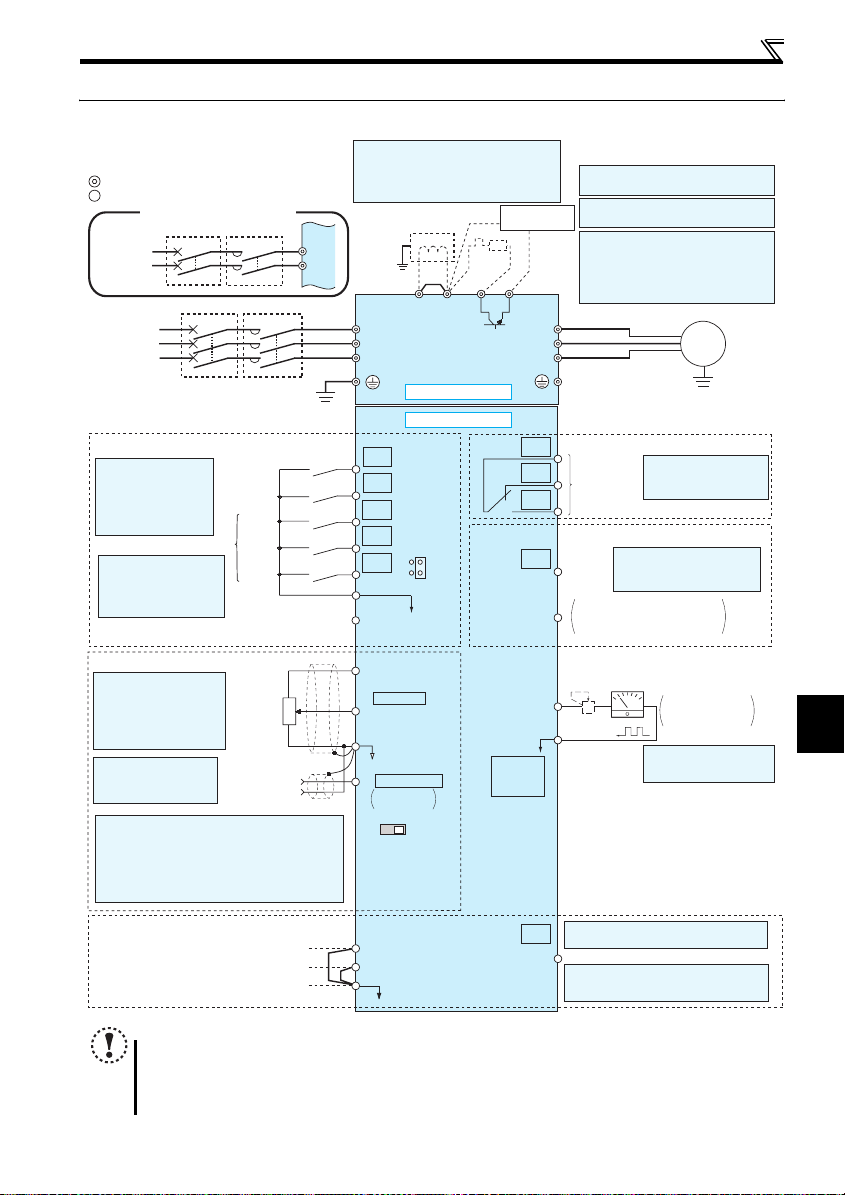
2.4 Wiring
2.4.1 Terminal connection diagram
Sink logic
Main circuit terminal
Control circuit terminal
Single-phase power input
Single-phase
AC power
supply
Three-phase
AC power
supply
MCCB MC
MCCB MC
R/L1
S/L2
(Ground)
*1. DC reactor (FR-HEL)
When connecting a DC reactor, remove the
jumper across P1 and P/+
Single-phase 100V power input model is not
compatible with DC reactor.
Earth
R/L1
S/L2
T/L3
Jumper
*1
P1 P/+
*6
R
*8
PR
N/-
*7
Brake unit
(Option)
*6 Terminal P1 is not available for single-
phase 100V power input model.
*7 A brake transistor is not built-in to the
0.1K and 0.2K.
*8 Brake resistor (FR-ABR, MRS type, MYS
type)
Install a thermal relay to prevent an
overheat and burnout of the brake resistor.
(The brake resistor can not be connected
to the 0.1K and 0.2K.)
U
V
W
Wiring
Motor
IM
Earth
(Ground)
Control input signals (No voltage input allowed)
The function of these
terminals can be
changed to the reset
signal, etc. with the input
terminal assignment
(Pr. 178 to Pr. 182)
Multi-speed selection
*2 When using terminals PC-
SD as a 24VDC power
supply, take care not to
short across terminals
PC and SD.
(Common for external power supply transistor)
Frequency setting signals (Analog)
*3 Terminal input specifications
can be changed by analog
input specifications
switchover (Pr. 73).
Terminal 10 and terminal 2
are used as PTC input
terminal (Pr. 561).
*4 It is recommended to
use 2W1kΩ when the
frequency setting signal
is changed frequently.
*5 Terminal input specifications can be changed by analog
input specifications switchover (Pr. 267). Set the
voltage/current input switch in the "V" position to select
voltage input (0 to 5V/0 to10V) and "I" (initial value) to
select current input (4 to 20mA).
To use terminal 4 (initial setting is current input), set "4"
in any of Pr.178 to Pr.182 (input terminal function
selection) to assign the function, and turn ON AU signal.
Safety stop signal
.
Forward
rotation start
Reverse
rotation start
High
speed
Middle
speed
Low
speed
Contact input common
24VDC power supply
3
Frequency
setting
potentiometer
1/2W1kΩ
*4
Terminal 4
input
(Current
input)
2
1
(+)
(-)
Shorting
Safe stop input (Channel 1)
Safe stop input (Channel 2)
Safe stop input common
wire
STF
STR
PC
Voltage/current
input switch
Main circuit
Control circuit
RH
RM
RL
SD
10(+5V)
2 0 to 5VDC
(0 to 10VDC)
5(Analog common)
4 4 to 20mADC
VI
S1
S2
SC
SOURCE
*2
0 to 5VDC
0 to 10VDC
SINK
*3
*5
Earth (Ground)
C
B
A
Relay output
(Fault output)
Relay output
Terminal functions vary
by Pr. 192 A,B,C terminal
function selection
Open collector output
RUN
SE
FM
SD
PU
connector
*5
SO
Terminal functions vary by
Pr. 190 RUN terminal function
Running
selection
Open collector output common
Sink/source common
Calibration resistor
*9
Terminal functions vary by Pr. 197 SO
terminal function selection
Safety monitor output *10
*10 Common terminal of terminal SO is
terminal SC. (Connected to terminal SD
inside of the inverter.)
+
-
*9 It is not necessary when
Indicator
(Frequency meter, etc.)
Moving-coil type
1mA full-scale
calibrating the indicator
from the operation panel.
2
INSTALLATION AND WIRING
NOTE
To prevent a malfunction caused by noise, separate the signal cables more than 10cm from the p ower cables. Also
separate the main circuit w ire of the input side an d the output side.
After wiring, wire offcuts must not be left in the inverter.
Wire offcuts can cause an alarm, failure or malfunction. Always keep the inverter clean. When drilling mounting holes
in an enclosure etc., take ca re not to allow chips and ot her foreign matter to enter the inverter.
The output of the single-phase power input model is three-phase 200V.
9
Wiring
r
2.4.2 Specification of main circuit terminal
Ter min al
Symbol
R/L1,
S/L2,
T/L3
∗1
U, V, W Inverter output Connect a three-phase s quirrel-cage motor.
P/+, PR Brake resistor con nection
P/+, N/- Brake unit connection
∗2 DC reactor connection
P/+, P1
∗1 When using single-phase power input, terminals are R/L1 and S/L2.
∗2 Terminal P1 is not available for single-phase 100V power input model.
Terminal Name Description
AC power input
Earth (Ground) For earthing (groundin g) the inverter chassis. Must be earthed (ground ed).
Connect to the commercia l power supply.
Keep these terminals op en when using the high p ower factor converter (F R-HC) or
power regeneration common converter (FR-CV).
Connect a brake resistor (FR-ABR, MRS type, MYS type) across terminals P/+ and PR.
(The brake resistor can no t be connected to the 0.1K and 0.2K.)
Connect the brake unit (FR-B U2), power regeneratio n common converter (FR-C V)
or high power factor conver ter (FR-HC).
Remove the jumper across terminals P/+ and P1 and connect a DC reactor.
Single-phase 100V power input model is not com patible with DC reactor.
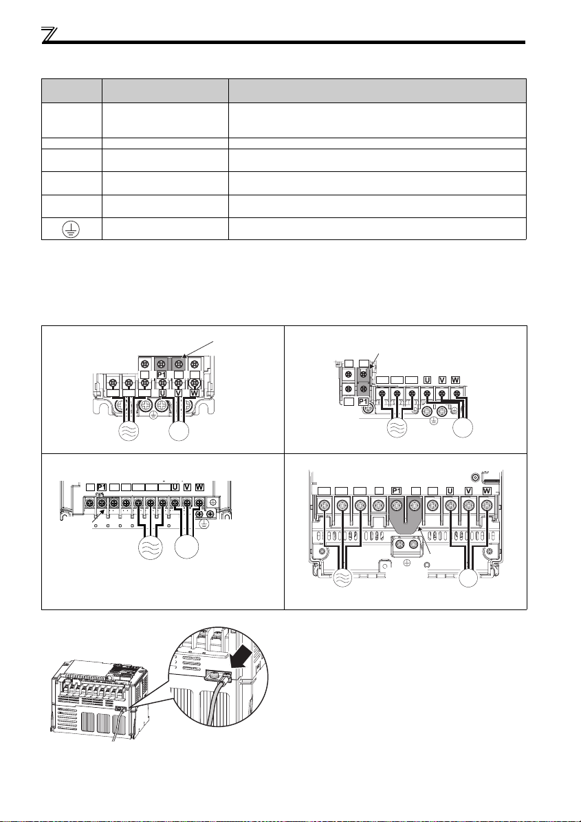
2.4.3 Terminal arrangement of the main circuit terminal, power supply and the motor wiring
zThree-phase 200V class
FR-D720-0.1K to 0.75K FR-D720-1.5K to 3.7K
Screw size (M3.5)
N/-
R/L1 S/L2 T/L3
Screw size
(M3.5)
IM
FR-D720-5.5K, 7.5K FR-D720-11K, 15K
Screw size (M5)
N/-
P/+ PR
MotorPower supply
R/L1 S/L2 T/L3
P/+ PR
Jumpe
Jumper
N/-
P/+
Screw size (M4)
R/L1 S/L2 T/L3
PR
Screw size
Power supply
Screw size (M5 for 11K, M6 for 15K)
R/L1 S/L2 T/L3
N/-
P/+
(M4)
PR
IM
Motor
Jumper
Power supply Motor
* For wiring to earth (ground) terminals of FR-D720-5.5K and 7.5K, use the earthing cable wiring space (marked with an arrow) to route the wires.
IM
Screw size (M5)
Power supply
Screw size
(M5)
Jumper
IM
Motor
10
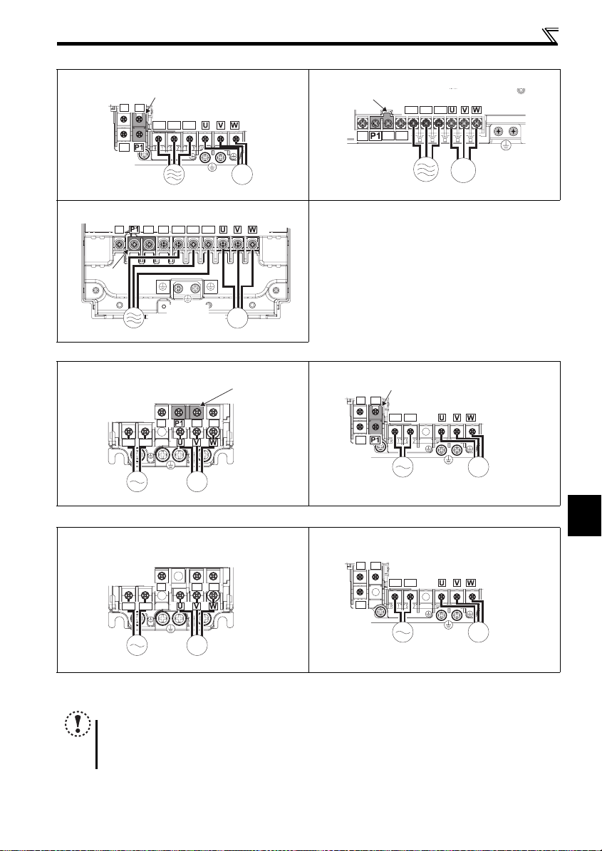
zThree-phase 400V class
r
FR-D740-0.4K to 3.7K FR-D740-5.5K, 7.5K
FR-D740-11K, 15K
N/-
Jumper
Power supply
Jumper
N/-
P/+
R/L1 S/L2 T/L3
PR
P/+
PR
(M4 for 11K, M5 for 15K)
Screw size (M4)
Screw size
Screw size (M4 for 11K, M5 for 15K)
R/L1 S/L2 T/L3
Screw size
(M4)
IM
MotorPower supply
IM
Motor
Jumper
N/-
zSingle-phase 200V class
FR-D720S-0.1K to 0. 75K FR-D720S-1.5K, 2.2K
Screw size (M3.5)
N/-
R/L1 S/L2
Jumpe
N/-
P/+ PR
PR
P/+
R/L1 S/L2 T/L3
P/+
PR
Jumper
Screw size (M4)
R/L1 S/L2
Screw size (M4)
IM
MotorPower supply
Wiring
Screw size
(M4)
Screw size
IM
(M3.5)
MotorPower supply
zSingle-phase 100V class
FR-D710W-0.1K to 0.4K FR-D710W-0.75K
Screw size (M3.5)
N/-
P/+ PR
R/L1 S/L2
Screw size
(M3.5)
IM
MotorPower supply
NOTE
Make sure the power cables are connected to the R/L1, S/L2, T/L3. (Phase need not be matched.) Never connect the
Connect the motor to U, V, W. Turning ON the forward rotation switch (signal) at this time rotates the motor
power cable to the U, V, W of the inverter. Doing so will damage the inverter.
counterclockwise when viewed from the load shaft.
Screw size
(M4)
IM
MotorPower supply
2
N/-
P/+
Screw size (M4)
R/L1 S/L2
PR
IM
Screw size
(M4)
MotorPower supply
INSTALLATION AND WIRING
11
Wiring
(1) Cable sizes etc., of the main control circuit terminals and earth (ground) terminals
Select the recommended cable size to ensure that a voltage drop will be 2% max.
If the wiring distance is long between the inverter and motor, a main circuit cable voltage drop will cause the motor torque to
decrease especially at the output of a low frequency.
The following table indicates a selection example for the wiring length of 20m.
Three-phase 200V class (when input power supply is 220V)
Crimping
Ter mi nal
Applicable Inverter
Model
FR-D720-0.1K to 0.75K M3.5 1.2 2-3.5 2-3 .5 2 2 2 14 14 2.5 2.5 2 .5
FR-D720-1.5K, 2.2K M4 1.5 2-4 2-4 2 2 2 14 14 2. 5 2.5 2.5
FR-D720-3.7K M4 1.5 5.5-4 5.5-4 3.5 3.5 3.5 12 12 4 4 4
FR-D720-5.5K M5 2.5 5.5-5 5.5-5 5.5 5.5 5.5 10 10 6 6 6
FR-D720-7.5K M5 2.5 14-5 8-5 14 8 5 .5 6 8 16 10 6
FR-D720-11K M5 2.5 14-5 14-5 14 14 14 6 6 16 16 16
FR-D720-15K M6 (M5) 4.4 22-6 22-6 22 22 14 4 4 25 2 5 16
Screw
Size ∗4
Tightening
Tor que
Ter min al
R/L1
·
m
N
S/L2
T/L3
HIV Cables, etc. (mm2) ∗1
R/L1
U, V, W
S/L2
T/L3
U, V, W
(ground)
Three-phase 400V class (when input power supply is 440V)
Crimping
N·m
Ter min al
R/L1
S/L2
T/L3
HIV Cables, etc. (mm2) ∗1
R/L1
U, V, W
S/L2
T/L3
U, V, W
(ground)
Ter mi nal
Applicable Inverter
Model
FR-D740-0.4K to 3.7K M4 1.5 2-4 2-4 2 2 2 1 4 14 2.5 2.5 2.5
FR-D740-5.5K M4 1.5 5.5-4 2-4 3.5 2 3.5 12 14 4 2.5 4
FR-D740-7.5K M4 1.5 5.5-4 5.5-4 3.5 3.5 3.5 12 12 4 4 4
FR-D740-11K M4 1.5 5.5-4 5.5-4 5.5 5.5 8 10 10 6 6 10
FR-D740-15K M5 2.5 8-5 8-5 8 8 8 8 8 10 10 10
Screw
Size ∗4
Tightening
Tor que
Single-phase 200V class (when input power supply is 220V)
Crimping
N·m
Ter min al
R/L1
S/L2
HIV Cables, etc. (mm2) ∗1
R/L1
U, V, W
S/L2
U, V, W
(ground)
Ter mi nal
Applicable Inverter
Model
FR-D720S-0.1K to 0.75 K M3.5 1.2 2- 3.5 2-3.5 2 2 2 14 14 2.5 2.5 2.5
FR-D720S-1.5K M4 1.5 2-4 2-4 2 2 2 14 14 2.5 2.5 2.5
FR-D720S-2.2K M4 1.5 5.5-4 2-4 3.5 2 3 .5 12 14 4 2.5 4
Screw
Size ∗4
Tightening
Tor que
Single-phase 100V class (when input power supply is 100V)
Crimping
N·m
Ter min al
R/L1
S/L2
HIV Cables, etc. (mm2) ∗1
R/L1
U, V, W
S/L2
U, V, W
(ground)
Ter mi nal
Applicable Inverter
Model
FR-D710W-0.1K to 0.4K M 3.5 1.2 2-3.5 2-3.5 2 2 2 14 14 2.5 2.5 2 .5
FR-D710W-0.75K M4 1.5 5.5-4 2-4 3.5 2 2 12 14 4 2.5 2.5
∗1 The cable size is that of the cable (HIV cable (600V class 2 vinyl-insulated cable) etc.) with continuous maximum permissible temperature of 75°C. Assumes
that the surrounding air temperature is 50°C or less and the wiring distance is 20m or less.
∗2 The recommended cable size is that of the cable (THHW cable) with continuous maximum permissible temperature of 75°C. Assumes that the surrounding
air temperature is 40°C or less and the wiring distance is 20m or less.
(Selection example for use mainly in the United States.)
∗3 The recommended cable size is that of the cable (THHW cable) with continuous maximum permissible temperature of 70°C. Assumes that the surrounding
air temperature is 40°C or less and the wiring distance is 20m or less.
(Selection example for use mainly in Europe.)
∗4 The terminal screw size indicates the terminal size for R/L1, S/L2, T/L3, U, V, W, PR, P/+, N/-, P1 and a screw for earthing (grounding).
Screw size for earthing (grounding) the FR-D720-15K is indicated in parenthesis.
For single-phase power input, the terminal screw size indicates the size of terminal screw for R/L1, S/L2, U, V, W, PR, P/+, N/-, P1 and a screw for earthing
(grounding).
Screw
Size ∗4
Tightening
Tor que
NOTE
Tighten the terminal screw to the specified torque. A screw that has been tightened too loosely can cause a short circuit or
malfunction. A screw that has been tightened too tightly can cause a short circuit or malfunction due to the unit breakage.
Use crimping terminals with insulation sleeve to wire the power supply and motor.
Earth
cable
Earth
cable
Earth
cable
Earth
cable
Cable Size
AWG ∗2
R/L1
S/L2
U, V, W
T/L3
Cable Size
AWG ∗2
R/L1
S/L2
U, V, W
T/L3
Cable Size
AWG ∗2
R/L1
U, V, W
S/L2
Cable Size
AWG ∗2
R/L1
U, V, W
S/L2
PVC Cables, etc. (mm2) ∗3
R/L1
S/L2
T/L3
U, V, W
Earth
(ground)
cable
PVC Cables, etc. (mm2) ∗3
R/L1
S/L2
T/L3
U, V, W
Earth
(ground)
cable
PVC Cables, etc. (mm2) ∗3
R/L1
S/L2
U, V, W
Earth
(ground)
cable
PVC Cables, etc. (mm2) ∗3
R/L1
S/L2
U, V, W
Earth
(ground)
cable
12
Wiring
The line voltage drop can be calculated by the following formula:
Line voltage drop [V]=
Use a larger diameter cable when the wiring distance is long or when it is desired to decrease the voltage drop (torque
reduction) in the low speed range.
(2) Earthing (Grounding) precautions
Leakage currents flow in the inverter. To prevent an electric shock, the inverter and motor must be earthed (grounded). This
inverter must be earthed (grounded). Earthing (Grounding) must conform to the requirements of national and local safety
regulations and electrical codes. (NEC section 250, IEC 536 class 1 and other applicable standards)
Use an neutral-point earthed (grounded) power supply for 400V class inverter in compliance with EN standard.
Use the dedicated earth (ground) terminal to earth (ground) the inverter. (Do not use the screw in the casing, chassis, etc.)
Use the thickest possible earth (ground) cable. Use the cable whose size is equal to or greater than that indicated on page
12 , and minimize the cable length. The earthing (grounding) point should b e as near as possible to the inverter.
POINT
To be compliant with the EU Directive (Low Voltage Directive), earth (ground) the inverter according to the
instructions on page 133.
3 × wire resistance[mΩ/m] × wiring distance[m] × current[A]
1000
13
2
INSTALLATION AND WIRING
Wiring
(3) Total wiring length
The overall wiring length for connection of a single motor or multiple motors should be within the value in the table
below.
100V, 200V class
Pr. 72 PWM frequency
400V class
Pr. 72 PWM frequency
selection Setting
(carrier frequency)
1 (1kHz) or less 200m 200m 300m 500m 500m
2 to15
(2kHz to 14.5kHz)
selection Setting
(carrier frequency)
1 (1kHz) or less 200m 200m 300 m 500m 500m
2 to15
(2kHz to 14.5kHz)
0.1K 0.2K 0.4K 0.75K
30m 100m 200m 300m 500m
0.4K 0.75K 1.5K 2.2K
30m 100m 200m 300m 500m
Total wiring length (FR-D720 -1.5K or more, FR-D72 0S-1.5K or more,
FR-D740-3.7K or more)
500m or less
300m
1.5K or
More
3.7K
or More
300m
300m+300m=600m
When driving a 400V class motor by the inverter, surge voltages attributable to the wiring constants may occur at the
motor terminals, deteriorating the insulation of the motor. Take the following measures 1) or 2) in this case.
1) Use a "400V class inverter-driven insulation-enhanced motor" and set frequency in Pr. 72 PWM frequency selection
according to wiring length
Wiring Length
50m or less 50m to 100m Exceeding 100m
Carrier frequency
14.5kHz or less 8kHz or less 2kHz or less
2) Connect the surge voltage suppression filter (FR-ASF-H/FR-BMF -H) on the inverter outpu t side.
NOTE
Especially for long-distance wiring, the inverter may be affected by a charging current caused by the stray
capacitances of the wiring, leading to a malfunction of the overcurrent protective function, fast response current limit
function, or stall prevention function or a malfunction or fault of the equipment connected on the inverter output side.
If malfunction of fast-response current limit function occurs, disable this function. If malfunction of stall prevention
function occurs, increa se the stall level. ( Refer to Pr. 22 Stall prevention operation level and Pr. 156 Stall prevention
operation selection in the chapter 4 of the Instruction Manual (applied))
Refer to Chapter 4 o f the Instruction Manual (Applied) for details of Pr. 72 PWM frequency selection. Refer to the manual
of the option for details of surge voltage suppression filter (FR-ASF-H/FR-BMF-H).
When using the automatic restart after instantaneous power failure function with wiring length exceeding below,
select without frequen cy search (Pr. 162 = "1, 11"). (
Refer to Chapter 4 of the Instruction Manual (Ap plied))
Motor capacity 0.1K 0.2K 0.4K or more
Wiring length 20m 50m 100m
14
2.4.4 Control circuit terminal
indicates that terminal functions can be selected using Pr. 178 to Pr. 182, Pr. 190, Pr. 192, Pr. 197 (I/O terminal function
selection). ( Refer to Chapter 4 of the Instruction Manual (Applied)).
(1) Input signal
Ter min al
Typ e
Symbol
STF Forward rotation start
STR Reverse rotatio n start
RH,
RM,
RL
SD
Contact input
PC
10
2
Frequency setting
4
5
10
2
PTC thermistor
Terminal Name Description Rated Specifications
Turn ON the STF signal to
start forward rotation and
turn it OFF to stop.
Turn ON the STR signal to
start reverse rotation and
turn it OFF to stop.
Multi-speed selection
Contact input common
(sink) (initial setting)
External transistor
common (source)
24VDC power supply
common
External transistor
common (sink)
(initial setting)
Contact input common
(source)
24VDC power supply Can be used as 24VDC 0.1A power supp ly.
Frequency setting pow er
supply
Frequency setting
(voltage)
Frequency setting
(current)
Frequency setting
common
PTC thermistor input
Multi-speed can be selec ted according to the
combination of RH, RM and RL signals.
Common terminal for co ntact input terminal (s ink logic)
and terminal FM.
When connecting the tran sistor output (open collector
output), such as a progra mmable controller, when
source logic is selected , connect the external po wer
supply common for trans istor output to this termin al to
prevent a malfunction c aused by undesirable c urrents.
Common output terminal for 24VDC 0.1A power
supply (PC terminal) .
Isolated from terminals 5 and SE.
When connecting the tran sistor output (open collector
output), such as a program mable controller, when sink
logic is selected, conne ct the external power s upply
common for transistor ou tput to this terminal to prevent
a malfunction caused by undesirable curren ts.
Common terminal for con tact input terminal (source
logic).
Used as power supply when connecting potentiometer
for frequency setting (spee d setting) from outside of
the inverter.
( Refer to Chapter 4 of the Instruction Manual
(Applied))
Inputting 0 to 5VDC (or 0 to 10V) provides the maximum
output frequency at 5V (10V) and makes input and output
proportional. Use
5VDC input (initial setting) and 0 to 10VDC.
Inputting 4 to 20mADC (or 0 to 5V, 0 to 10V) provides
the maximum output fre quency at 20mA and mak es
input and output proportio nal. This input signal is v alid
only when the AU signa l is ON (terminal 2 inpu t is
invalid). To use terminal 4 (initial setting is cu rrent
input), set "4" in any of Pr.178 to Pr.182 (input terminal
function selection) to assign the function, an d turn ON
AU signal.
Use Pr. 267 to switch from among input 4 to 20mA
(initial setting), 0 to 5VDC an d 0 to 10VDC. Set the
voltage/current input switc h in the "V" position to select
voltage input (0 to 5V/0 to 10V).
( Refer to Chapter 4 of the Instruction Manual
(Applied)).
Frequency setting signal (t erminal 2, 4) common
terminal. Do not earth (gro und).
For connecting PTC thermistor output.
When PTC thermistor protec tion is valid (Pr. 561 ≠
"9999"), terminal 2 is not a vailable for frequenc y
setting.
Pr. 73
When the STF and STR
signals are turned ON
simultaneously, the stop
command is given.
to switch between input 0 to
Input resistance 4.7kΩ
Voltage when contacts are
open
21 to 26VDC
When contacts are shortcircuited
4 to 6mADC
——
Power supply voltage rang e
22 to 26.5VDC
permissible load curre nt
100mA
5VDC
permissible load curre nt
10mA
Input resistance10kΩ ± 1kΩ
Permissible maximum
voltage 20VDC
Current input:
Input resistance 233Ω ± 5Ω
Maximum permissib le
current 30mA
Voltage input:
Input resistance10kΩ ± 1kΩ
Permissible maximum
voltage 20VDC
Current input
(initial status)
——
Adaptive PTC thermistor
specification
Heat detecti on resistanc e :
500
Ω
to 30kΩ (Set by
Voltage input
Pr. 561
Wiring
Refer to
Instruction
Manual
(applied)
)
Page
62
64
18
59, 66
2
59, 66
60, 69
INSTALLATION AND WIRING
15
Wiring
NOTE
Set Pr. 267 and a voltage/current input s witch correctly, then input analog signals in accordan ce with the settings.
Applying a voltage with voltage/current input switch in "I" position (current input is selected) or a current with switch in
"V" position (voltage input is selected) could cause component damage of the inverter or analog circuit of output
devices.
(2) Output signal
Ter min al
Typ e
A, B, C
Relay
RUN Inverter runn ing
Open collector
SE
FM For meter
Pulse
(3) Communication
Typ e
RS-485
(4) Safety stop signal
Ter min al
Symbol
S1
S2
SO
SC
Terminal Name Description Rated Specifications
Symbol
Relay output (fault
output)
Open collector
output common
Terminal
Symbol
— PU connector
Terminal Name Description Rated Specifications
Safety stop input
(Channel 1)
Safety stop input
(Channel 2)
Safety monitor output
(open collector output)
Safety stop input
terminal common
1 changeover contact o utput indicates that the inverter
protective function has activated and the outp ut stopped.
Fault: discontinuity a cross B-C (continuity a cross A-C),
Normal: continuity acr oss B-C (discontinuity across A-C)
Switched Low when the inverter output frequen cy is equal
to or higher than the starting fr equency (initial value 0.5H z).
Switched High during stop or DC injection br ake operation.
(Low is when the ope n collector output transi stor is ON
(conducts). High is when the transistor is OFF (does not
conduct).)
Common terminal of terminal RUN. — —
Select one e.g. output
frequency from monitor items.
Not output during inverter reset.
Not output during inverter reset.
The output signal is proportional
to the magnitude of the
corresponding monitoring item.
Output item:
Output frequency (init ial
setting)
Contact capacity:230VAC
0.3A
(power factor =0.4)
30VDC 0.3A
Permissible load 24VDC
(maximum 27VDC) 0.1A
(a voltage drop is 3.4V
maximum when the signal
is ON)
Permissible load curre nt
1mA
1440 pulses/s at 60Hz
Terminal Name Description
With the PU connecto r, communication can be made throu gh RS-485.
Conforming standard: EIA-48 5 (RS-485)
Transmission format: Multidrop lin k
Communication speed: 4800 to 38400bps
Overall length: 500m
Terminals S1 and S2 are for safety stop input signals used
with the safety relay modu le. Terminals S1 and S2 are used
simultaneously (dual ch annel). Inverter output is shut off by
shortening/opening ac ross terminals S1 and S C and across
S2 and SC. In the initi al status, terminals S1 and S2 are
shorted with terminal SC by shortening wire.
Remove the shortening w ire and connect the s afety relay
module when using the safety stop function.
The signal indicates the s tatus of safety stop input. L ow
indicates safe state, and High indi cates drive enabled or fault
detected.
(Low is when the open collector output transistor is ON
(conducts). High is when the transistor is OFF (do es not
conduct).)
If High is output when both of terminals S1 and S2 are open,
refer to the Safety stop function instruction manual (BCN-A211508-
000) for the cause and countermeasure.
Common terminal for termin als S1, S2 and SO. Connected to
terminal SD inside of the inverter.
Input resistance: 4.7kΩ
Current: 4 to 6 mA
(In case of shorted to
SC)
Voltage: 21 to 26 V
(In case of open from
SC)
Load: 24VDC/0.1A max.
Voltage drop: 3.4V max.
(In case of 'ON' state)
----------
Reference
Page
Instruction
Manual
(applied)
Instruction
Manual
(applied)
Instruction
Manual
(applied)
Reference
Page
24
Reference
Page
22
16
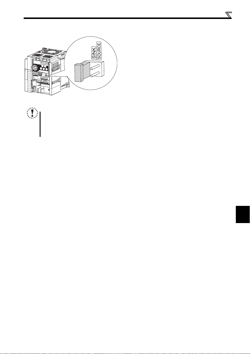
2.4.5 Changing the control logic
NOTE
Fully make sure that th e front cover has bee n reinstalled securely.
The capacity plate is placed on the front cover and the rat ing plate is on the invert er. Since these plates have the
same serial numbers, always reinstall the remove d cover onto the original inverter.
The sink-source logic change-over jumper connector must be fitted in only one of those positions. If it is fitted in both
positions at the same time, the inverter may be damaged.
Wiring
The input signals are set to sink logic (SINK) when shipped from
the factory.
To change the control logic, the jumper connector above the
control terminal must be moved to the other position.
Change the jumper connector in the sink logic (SINK) position
to source logic (SOURCE) position using tweezers, a pair of
long-nose pliers etc. Change the jumper connector position
before switching power ON.
17
2
INSTALLATION AND WIRING
Wiring
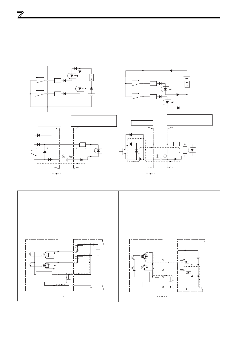
(1) Sink logic type and source logic type
In sink logic, a signal switches ON when a current flows from the corresponding signal input terminal.
Terminal SD is common to the contact input signals. Terminal SE is common to the open collector output signals.
In source logic, a signal switches ON when a current flows into the corresponding signal input terminal.
Terminal PC is common to the contact input signals. Terminal SE is common to the open collector output signals.
Current flow concerning t he input/output signa l when sink logic is
selected
Sink logic
Current
STF
STR
SD
R
R
Sink
connector
Current flow concerni ng the input/output sign al when source logic is
selected
Source logic
PC
Current
STF
R
STR
R
Source
connector
DC input (sink type)
24VDC
Current flow
<Example: QX40>
TB1
R
TB17
R
Inverter
RUN
SE
When using an external power supply for trans istor outpu t
Sink logic type
Use terminal PC as a common terminal, and perform
wiring as shown below. (Do not connect terminal SD of the
inverter with terminal 0V of the external power supply.
When using terminals PC-SD as a 24VDC power supply,
do not install an external power supply in parallel with the
inverter. Doing so may cause a malfunction in the inverter
due to undesirable currents.)
STF
STR
PC
SD
Current flow
Inverter
24VDC
(SD)
QY40P type transistor
output unit
Constant
voltage
circuit
TB1
TB2
TB17
TB18
24VDC
DC input (source type)
Inverter
RUN
SE
24VDC
Current flow
<Example: QX80>
TB1
R
TB18
R
Source logic type
Use terminal SD as a common terminal, and perform
wiring as shown below. (Do not connect terminal PC of the
inverter with terminal +24V of the external power supply.
When using terminals PC-SD as a 24VDC power supply,
do not install an external power supply in parallel with the
inverter. Doing so may cause a malfunction in the inverter
due to undesirable currents.)
PC
STF
STR
24VDC
SD
Current flow
Inverter
24VDC
(SD)
QY80 type transistor
output unit
Constant
voltage
Fuse
circuit
TB1
TB2
TB17
TB18
18
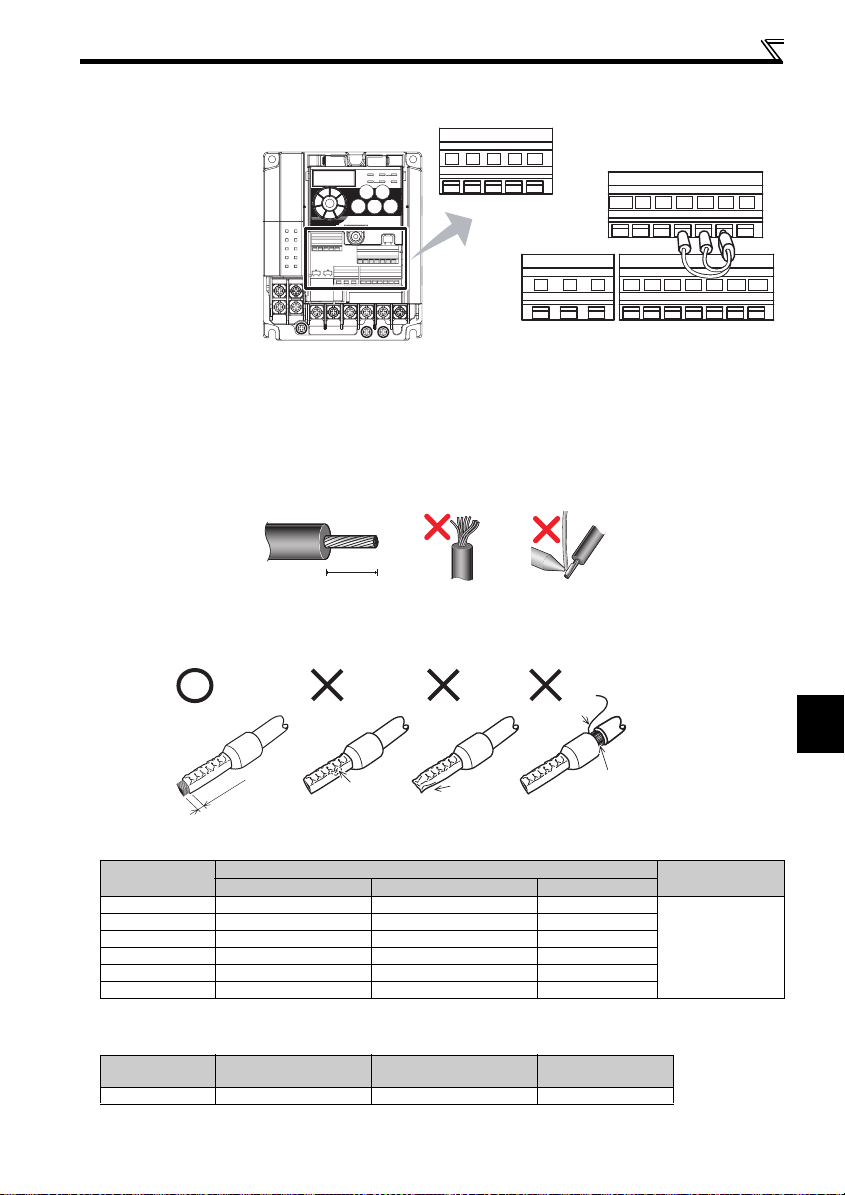
2.4.6 Wiring of control circuit
(1) Standard control circuit terminal layout
Recommend wire size:
0.3mm
2
to 0.75mm
2
10 2 5 4
Wiring
FM
RUN SE S1 S2 SCSO
CBA
SD
STF
PCSDRHRMRL
STR
(2) Wiring method
zWiring
Use a blade terminal and a wire with a sheath stripped off for the control circuit wiring. For a single wire, strip off the sheath of
the wire and apply directly.
Insert the blade terminal or the single wire into a socket of the terminal.
1) Strip off the sheath about the length below. If the length of the sheath peeled is too long, a short circuit may occur
among neighboring wires. If the length is too short, wires might come off.
Wire the stripped wire after twisting it to prevent it from becoming loose. In addition, do not solder it.
2) Crimp the blade terminal.
Insert wires to a blade terminal, and check that the wires come out for about 0 to 0.5 mm from a sleeve.
Check the condition of the blade terminal a fter crimping. Do not use a blade terminal of which th e crimping is
inappropriate, or the face is damaged.
Sleeve
0 to 0.5mm
Shell
Wire stripping length
10mm
Wire
Damaged
Crumpled tip
Unstranded
wires
Wires are not inserted
into the shell
2
Blade terminals available on the market: (as of Oct. 2008)
zPhoenix Contact Co.,Ltd.
Wire Size (mm2)
0.3 AI 0,5-10WH — —
0.5 AI 0,5-10 WH — AI 0,5-10WH-GB
0.75 AI 0,75-10GY A 0,75-10 AI 0,75-10GY-GB
1 AI 1-10RD A 1-10 AI 1-10RD/1000GB
1.25, 1.5 AI 1,5-10BK A1,5-10 AI 1,5-10B K/1000GB
0.75 (for two wires) AI-TWIN 2 x 0,75-10GY — —
*A blade terminal with an insulation sleeve compatible with MTW wire which has a thick wire insulation
with insulation sleeve without insulation sleeve for UL wire*
Blade Terminal Model
zNICHIFU Co.,Ltd.
Wire Size (mm2)
0.3 to 0.75 BT 0.75-11 VC 0.75 NH 67
Blade terminal product
number
Insulation product number
Blade terminal
crimping tool
Blade terminal
crimping t ool
CRIMPFOX ZA3
INSTALLATION AND WIRING
19
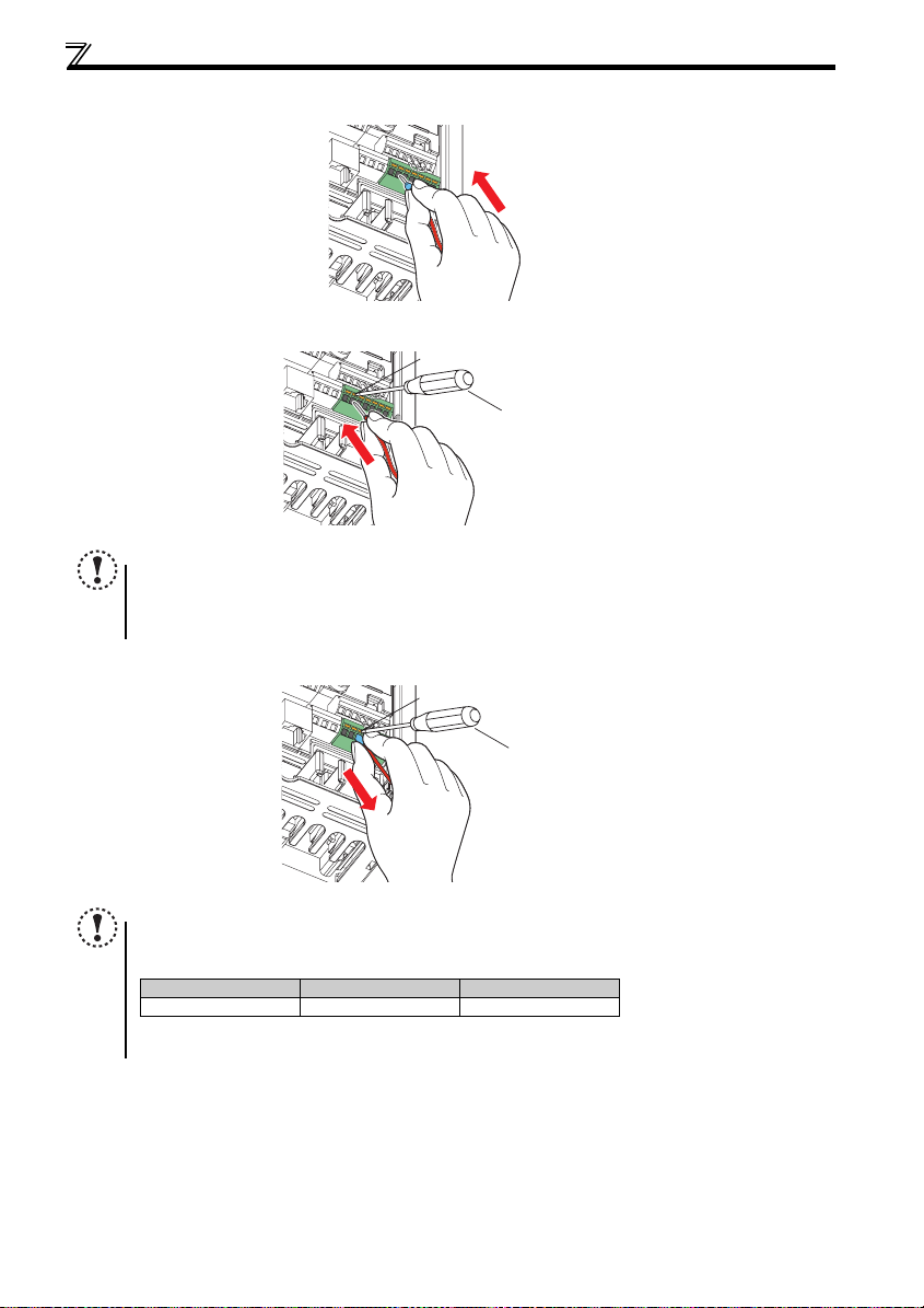
Wiring
r
r
3) Insert the wire into a socket.
When using a single wire or a stranded wire without a blade terminal, push an open/close button all the way down
with a flathead screw driver, and insert the wire.
NOTE
When using a stranded wire without a blade terminal, twist enough to avoid short circuit with a nearby terminals or
wires.
Place the flathead screwdriver vert ical to the open/clo se button. In case the blade tip slips, it may cause to d amage of
inverter or injury.
zWire removal
Pull the wire with pushing the open/close button all the way down firmly with a flathead screwdriver.
Open/close button
Flathead screwdrive
Open/close button
20
Flathead screwdrive
NOTE
Use a small flathead scr ewdriver (Tip thickness: 0.4mm/tip width: 2.5mm).
If a flathead screwdriver with a narrow tip is used, terminal block may be damaged.
Introduced products :(as of Oct. 2008)
Product Typ e Maker
Flathead screwdriver SZF 0- 0,4 x 2,5 Phoenix Contact Co.,Ltd.
Place the flathead screwdriver vert ical to the open/clo se button. In case the blade tip slips, it may cause to d amage of
inverter or injury.
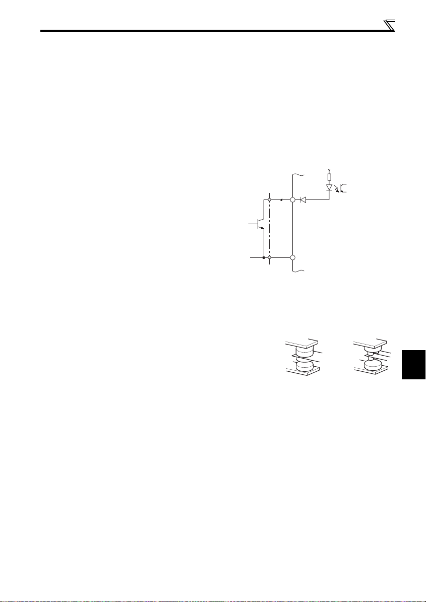
Wiring
(3) Control circuit common terminals (SD, 5, SE)
Terminals SD, SE and 5 are common terminals for I/O signals.(All common terminals are isolated from each other.) Do not
earth them. Avoid connecting the terminal SD and 5 and the terminal SE and 5.
Terminal is a common terminal for the contact input terminals (STF, STR, RH, RM, RL) and frequency output signal (FM). The
open collector circuit is isolated from the internal control circuit by photocoupler
Terminal 5 is a common terminal for the frequency setting signals (terminals 2 or 4). It should be protected from external nois e
using a shielded or twisted cable.
Terminal SE is a common terminal for the open collector output terminal (RUN). The contact input circuit is isolated from the
internal control circuit by photocoupler.
(4) Signal inputs by contactless switches
The contacted input terminals of the inverter (STF, STR,
RH, RM, RL) can be controlled using a transistor
instead of a contacted switch as shown on the right.
External signal input using transistor
(5) Wiring instructions
1) It is recommended to use the cables of 0.3mm2 to 0.75mm2 gauge for connection to the control circuit terminals.
2) The maximum wiring length should be 30m (200m for terminal FM).
3) Do not short across terminals PC and SD. Inverter may be damaged.
4) Use two or more parallel micro-signal contacts or twin contacts to prevent
contact faults when using contact inputs since the control circuit input signals
are micro-currents.
+24V
STF, etc.
Inverter
SD
2
Micro signal contacts Twin contacts
5) Use shielded or twisted cables for connection to the control circuit terminals
and run them away from the main and power circuits (including the 200V relay sequence circuit).
6) Do not apply a voltage to the contact input terminals (e.g. STF) of the control circuit.
7) Always apply a voltage to the fault output terminals (A, B, C) via a relay coil, lamp, etc.
INSTALLATION AND WIRING
21
 Loading...