

Page 1
INVERTER
MITSUBISHI
ELECTRIC
FR-D700 SC
INSTALLATION GUIDELINE
FR-D720S-008SC to 100SC-EC
FR-D740-012SC to 160SC-EC
Thank you for choosing this Mitsubishi Electric inverter.
Please read through this Installation Guideline and the enclosed CD ROM to operate this inverter
correctly.
Do not use this product until you have a full knowledge of the equipment, the safety information and the
instructions.
Please forward this Installation Guideline and the CD ROM to the end user.
CONTENTS
PRODUCT DESCRIPTION ................................................................................................... 1
1
INSTALLATION OF THE INVERTER AND INSTRUCTIONS................................................. 2
2
OUTLINE DIMENSION DRAWING...................................................................................... 4
3
WIRING ............................................................................................................................... 5
4
PRECAUTIONS FOR USE OF THE INVERTER ................................................................... 13
5
FAILSAFE OF THE SYSTEM WHICH USES THE INVERTER ..............................................15
6
PARAMETER ..................................................................................................................... 16
7
TROUBLESHOOTING........................................................................................................ 21
8
MAINTENANCE AND INSPECTION .................................................................................. 24
9
SPECIFICATIONS .............................................................................................................. 25
10
APPENDIX ........................................................................................................................ 26
A
Art. no.: 260530
14 02 2013
Version check
Version A
700
ORIGINAL INSTRUCTION
Page 2

Print Date Art. no. Revision
02/2013 akl 260530-A First edition
For Maximum Safety
앫
Mitsubishi Electric transistorized inverters are not designed or manufactured to be used in equipment or systems in situations that
can affect or endanger human life.
When considering this product for operation in special applications such as machinery or systems used in passenger transportation
앫
medical, aerospace, atomic power, electric power, or submarine repeating applications, please contact your nearest Mitsubishi
Electric sales representative.
앫 Although this product was manufactured under conditions of strict quality control, you are strongly advised to install safety
devices to prevent serious accidents when it is used in facilities where breakdowns of the product are likely to cause a serious
accident.
앫 Please do not use this product for loads other than three-phase induction motors.
앫 Please check upon receiving of the inverter whether this instruction manual corresponds to the delivered inverter. Compare the
specifications on the capacity plate with the specifications given in this manual.
,
Page 3
1About this Document
DANGER
CAUTION
CAUTION
DANGER
This document is the original mounting instruction.
1.1 Documentations for the FR-D700 SC Inverter
These manuals describe the mounting of the FR-D700 SC frequency inverter.
Mounting of any additional options is described in separated manuals. The installation, configuration and commissioning of the
FR-D700 SC inverter is described in the "Inverter FR-D700 SC Instruction Manual". This document provides guidance on the safe
use of the FR-D700 SC. Detailed technical information not included here can be found in manuals referred to in this document.
These can be obtained free of charge from our website at www.mitsubishi-automation.com.
The following manuals contain further information about the inverter:
앫 Inverter FR-D700 SC Instruction Manual,
앫 Transistorized Inverter FR-D700 SC Safety stop function Instruction Manual,
앫 Beginner‘s Manual of the Frequency Inverters FR-D700, FR-E700, FR-F700, and FR-A700,
앫 Manual for Frequency Inverters and EMC.
In addition mounting protective devices also requires specific technical skills which are not detailed in this documentation.
1.2 Function of this Document
These manuals instruct the technical staff of the machine manufacturer and/or of the machine operator on the safe mounting of
the FR-D700 SC inverter.
These manuals do not provide manuals for operating the machine in which the safety control system is, or will be, integrated.
Information of this kind will be found in the operating manuals for the machine.
2 Safety Instructions
Do not attempt to install, operate, maintain or inspect the inverter until you have read through this Installation Guideline and
appended documents carefully and can use the equipment correctly. Do not use the inverter until you have a full knowledge of
the equipment, safety information and instructions. In this Installation Guideline, the safety instruction levels are classified into
"DANGER" and "CAUTION".
Personnel health and injury warnings.
Failure to observe the precautions described here can result in serious health and injury hazards.
Equipment and property damage warnings.
Failure to observe the precautions described here can result in serious damage to the equipment or other
property.
Note that even the level may lead to a serious consequence according to conditions. Please follow strictly the instructions
of both levels because they are important to personnel safety.
2.1 Safety Persons
The FR-D700 SC inverter may only be mounted by safety persons. Safety persons are defined as persons who …
앫 ...have undergone the appropriate technical training. Please note appropriate technical training is available from your local
Mitsubishi Electric office.
Please contact your local office for locations and schedules.
앫 ...have been instructed by the responsible machine operator in the operation of the machine and the current valid safety
guidelines and
앫 ...have access to the operating manuals of the FR-D700 SC inverter and have read and familiarised themselves with them and
앫 ...have access to the operating manuals for the protective devices (e. g. light curtain) connected to the safety control system
and have read and familiarised themselves with them.
2.2 Applications of the Device
The FR-D700 SC is a variable speed drive, which can be used in safety installations.
The FR-D700 SC series inverter includes the safety functionality "Safe Torque Off", which can be used in accordance with
ISO13849-1/EN954-1 Category 3 IEC60204-1 Stop category 0.
For any use in safety installation we refer to the "Transistorized Inverter FR-D700 SC Safety stop function Instruction Manual".
The degree of safety actually attained depends on the external circuit, the realisation of the wiring, the parameter configuration,
the choice of the pick-ups and their location at the machine. Opto-electronic and tactile safety sensors (e. g. light curtains, laser
scanners, safety switches, sensors, emergency-stop buttons) are connected to the modular safety control system and are linked
logically. The corresponding actuators of the machines or systems can be switched off safely via the switching outputs of the
safety control system.
2.3 Correct Use
The FR-D700 SC inverter may only be used within specific operating limits (voltage, temperature, etc., refer to the technical data
and to the name plate on the device). It may only be used by specialist personnel and only at the machine at which it was mounted
and initially commissioned by specialist personnel in accordance with the "Inverter FR-D700 SC Instruction Manual" and "Transistorized
Inverter FR-D700 SC Safety stop function Instruction Manual".
Mitsubishi Electric Co. accepts no claims for liability if the equipment is used in any other way or if modifications are made to the
device, even in the context of mounting and installation.
The bus capacitor discharge time is 10 minutes. Before starting wiring or inspection, switch power off, wait for more than 10 minutes
and check for residual voltage between terminal P/+ and N/– with a meter etc., to avoid a hazard of electrical shock.
,
Page 4
3 General Protective Notes and Protective Measures
DANGER
CAUTION
CAUTION
Observe the protective notes and measures!
Please observe the following items in order to ensure proper use of the FR-D700 SC inverter.
앫 When mounting, installing and using the FR-D700 SC inverter, observe the standards and directives applicable in your country.
앫
The national rules and regulations apply to the installation, use and periodic technical inspection of the FR-D700 SC, in particular:
– Machinery Directive 98/37/EC (from 29.12.2009 Machinery Directive 2006/42/EC),
– EMC Directive 2004/108/EC,
– Provision and Use of Work Equipment Directive 89/655/EC,
– Low-Voltage Directive 2006/95/EC,
– Work safety regulations/safety rules.
앫 Manufacturers and owners of the machine on which a FR-D700 SC inverter is used are responsible for obtaining and observing
all applicable safety regulations and rules.
앫 It is imperative that the notices, in particular the test notices of the manuals be observed.
앫 The tests must be carried out by specialised personnel or specially qualified and authorised personnel and must be recorded
and documented to ensure that the tests can be reconstructed and retraced at any time by third parties.
3.1 Electric Shock Prevention
앫
While power is ON or when the inverter is running, do not open the front cover or wiring cover. Otherwise you may get an electric
앫
Do not run the inverter with the front cover removed. Otherwise you may access the exposed high-voltage terminals or the charging
part of the circuitry and get an electric shock.
앫
Even if power is OFF, do not remove the front cover except for wiring or periodic inspection. You may access the charged inverter
circuits and get an electric shock.
앫 Before starting wiring or inspection, check to make sure that the operation panel indicator is OFF, wait for at least 10 minutes
after the power supply has been switched off, and check that there are no residual voltage using a tester or the like. The capacitor
is charged with high voltage for some time after power OFF and it is dangerous.
앫 This inverter must be earthed (grounded). Earthing (Grounding) must conform to the requirements of national and local safety
regulations and electrical codes. (NEC section 250, IEC 536 class 1 and other applicable standards)
Use a neutral-point earthed (grounded) power supply for 400 V class inverter in compliance with EN standard.
앫 Any person who is involved in the wiring or inspection of this equipment should be fully competent to do the work.
앫 Always install the inverter before wiring. Otherwise you may get an electric shock or be injured.
앫 If your application requires by installation standards an RCD (residual current device) as up stream protection please select
according to DIN VDE 0100-530 as following:
Single phase inverter type A or B
Three phase inverter only type B
(Additional instructions on the use of a residual current device are contained on page 27.)
앫 Perform setting dial and key operations with dry hands to prevent an electric shock. Otherwise you may get an electric shock.
앫 Do not subject the cables to scratches, excessive stress, heavy loads or pinching. Otherwise you may get an electric shock.
앫 Do not replace the cooling fan while power is on. It is dangerous to replace the cooling fan while power is on.
앫 Do not touch the printed circuit board or handle the cables with wet hands. You may get an electric shock.
앫 When measuring the main circuit capacitor capacity, the DC voltage is applied to the motor for 1 s at powering off. Never touch
the motor terminal, etc. right after powering off to prevent an electric shock.
shock.
3.2 Fire Prevention
앫 Install the inverter on a nonflammable wall without holes (so that nobody can touch the inverter heatsink on the rear side, etc.).
Mounting it to or near flammable material can cause a fire.
앫 If the inverter has become faulty, switch off the inverter power. A continuous flow of large current could cause a fire.
앫 When using a brake resistor, make up a sequence that will turn off power when an alarm signal is output. Otherwise, the brake
resistor may excessively overheat due to damage of the brake transistor and such, causing a fire.
앫 Do not connect a resistor directly to the DC terminals P/+, N/–. This could cause a fire and destroy the inverter. The surface
temperature of braking resistors can far exceed 100 °C for brief periods. Make sure that there is adequate protection against
accidental contact and a safe distance is maintained to other units and system parts.
3.3 Injury Prevention
앫 Apply only the voltage specified in the instruction manual to each terminal. Otherwise, burst, damage, etc. may occur.
앫 Ensure that the cables are connected to the correct terminals. Otherwise, burst, damage, etc. may occur.
앫 Always make sure that polarity is correct to prevent damage, etc. Otherwise, burst, damage, etc. may occur.
앫 While power is on or for some time after power-off, do not touch the inverter as it is hot and you may get burnt.
Page 5
4 Additional Instructions
CAUTION
Operating Condition
Ambient temperature –10 °C to +50 °C (non-freezing)
Ambient humidity 90 % RH or less (non-condensing)
Storage temperature
–20 °C to +65 °C
햲
Atmosphere Indoors (free from corrosive gas, flammable gas, oil mist, dust and dirt)
Altitude
Maximum 1000m above sea level for standard operation. After that derate by 3 % for every extra 500 m up to
2500 m (91 %)
Vibration 5.9 m/s² or less at 10 to 55 Hz (directions of X, Y, Z axes)
CAUTION
CAUTION
DANGER
Also note the following points to prevent an accidental failure, injury, electric shock, etc.
4.1 Transportation and Installation
앫 Transport the product using the correct method that corresponds to the weight. Failure to observe this could lead to injuries.
앫 Do not stack the inverter boxes higher than the number recommended.
앫
Ensure that installation position and material can withstand the weight of the inverter. Install according to the information in the
instruction manual.
앫 Do not install or operate the inverter if it is damaged or has parts missing. This can result in breakdowns.
앫 When carrying the inverter, do not hold it by the front cover or setting dial; it may fall off or fail.
앫 Do not stand or rest heavy objects on the product.
앫 Check the inverter mounting orientation is correct.
앫 Prevent other conductive bodies such as screws and metal fragments or other flammable substance such as oil from entering
the inverter.
앫 As the inverter is a precision instrument, do not drop or subject it to impact.
앫 Use the inverter under the following environmental conditions. Otherwise, the inverter may be damaged.
햲
Temperature applicable for a short time, e.g. in transit.
4.2 Wiring
앫 Do not install assemblies or components (e. g. power factor correction capacitors) on the inverter output side, which are not
approved from Mitsubishi Electric.
앫 The direction of rotation of the motor corresponds to the direction of rotation commands (STF/STR) only if the phase sequence
(U, V, W) is maintained.
4.3 Test Operation and Adjustment
앫
Before starting operation, confirm and adjust the parameters. A failure to do so may cause some machines to make unexpected motions.
4.4 Operation
앫 When you have chosen the retry function, stay away from the equipment as it will restart suddenly after an alarm stop.
앫 Since pressing key may not stop output depending on the function setting status, provide a circuit and switch separately
to make an emergency stop (power off, mechanical brake operation for emergency stop, etc).
앫 Make sure that the start signal is off before resetting the inverter alarm. A failure to do so may restart the motor suddenly.
앫 The inverter can be started and stopped via the serial port communications link or the field bus. However, please note that
depending on the settings of the communications parameters it may not be possible to stop the system via these connections
if there is an error in the communications system or the data line. In configurations like this it is thus essential to install
additional safety hardware that makes it possible to stop the system in an emergency (e.g. controller inhibit via control signal,
external motor contactor etc). Clear and unambiguous warnings about this must be posted on site for the operating and
service staff.
앫 The load used should be a three-phase induction motor only. Connection of any other electrical equipment to the inverter
output may damage the inverter as well as the equipment.
앫 Do not modify the equipment.
앫 Do not perform parts removal which is not instructed in this manual. Doing so may lead to fault or damage of the inverter.
Page 6
앫
CAUTION
CAUTION
CAUTION
CAUTION
The electronic thermal relay function does not guarantee protection of the motor from overheating. It is recommended to install
both an external thermal and PTC thermistor for overheat protection.
앫 Do not use a magnetic contactor on the inverter input for frequent starting/stopping of the inverter. Otherwise, the life of the
inverter decreases.
앫 Use a noise filter to reduce the effect of electromagnetic interference and follow the accepted EMC procedures for proper
installation of frequency inverters. Otherwise nearby electronic equipment may be affected.
앫 Take appropriate measures regarding harmonics. Otherwise this can endanger compensation systems or overload generators.
앫 When a 400 V class motor is inverter-driven, please use an insulation-enhanced motor or measures taken to suppress surge
voltages. Surge voltages attributable to the wiring constants may occur at the motor terminals, deteriorating the insulation of
the motor.
앫 When parameter clear or all clear is performed, set again the required parameters before starting operations. Each parameter
returns to the initial value.
앫
The inverter can be easily set for high-speed operation. Before changing its setting, fully examine the performances of the motor
and machine.
앫
The DC braking function of the frequency inverter is not designed to continuously hold a load. Use an electro-mechanical holding
brake on the motor for this purpose.
앫 Before running an inverter which had been stored for a long period, always perform inspection and test operation.
For prevention of damage due to static electricity, touch nearby metal before touching this product to eliminate static electricity
앫
from your body.
앫 If you are installing the inverter to drive a three-phase device while you are contracted for lighting and power service, consult
your electric power supplier.
4.5 Emergency Stop
앫
Provide a safety backup such as an emergency brake which will prevent the machine and equipment from hazardous conditions
if the inverter fails.
앫
When the breaker on the inverter primary side trips, check for the wiring fault (short circuit), damage to internal parts of the inverter,
etc. Identify the cause of the trip, then remove the cause and power on the breaker.
앫
When the protective function is activated (i. e. the frequency inverter switches off with an error message), take the corresponding
corrective action as described in the inverter manual, then reset the inverter, and resume operation.
4.6 Maintenance, Inspection and Parts Replacement
앫 Do not carry out a megger (insulation resistance) test on the control circuit of the inverter. It will cause a failure.
It is recommended to make the following checks periodically:
앫 Check for loose screws in the terminal block. Retighten any loose screws.
앫 Check for dust accumulation on the inverter. Clean the heat sink and the cooling fan of the inverter.
앫 Check for unusual noise generated by the inverter. Retighten installation screw.
앫 Check for the operation condition. Keep the operation condition of inverter as written in the manual.
4.7 Disposal of the Inverter
앫 Disposal of unusable or irreparable devices should always occur in accordance with the applicable country-specific waste-
disposal regulations (e.g. European Waste Code 16 02 14).
5 General Instructions
Many of the diagrams and drawings in instruction manuals show the inverter without a cover, or partially open. Never run the
inverter in this status. Always replace the cover and follow instruction manuals when operating the inverter.
NOTES
앫
The FR-D700 SC complies to the EMC Directive 2004/108/EC and the relevant requirements of EN61800-3:2004 (Second environment/
PDS category "C3").
Therefore the FR-D700 SC is only suitable for use in an industrial environment and not for private use. If you want to use
FR-D700 SC inverter in first environment you will have to add an external RFI filter.
앫 The FR-D700 SC complies to the Low Voltage Directive 2006 and the relevant requirements of EN61800-5-1:2007.
Page 7
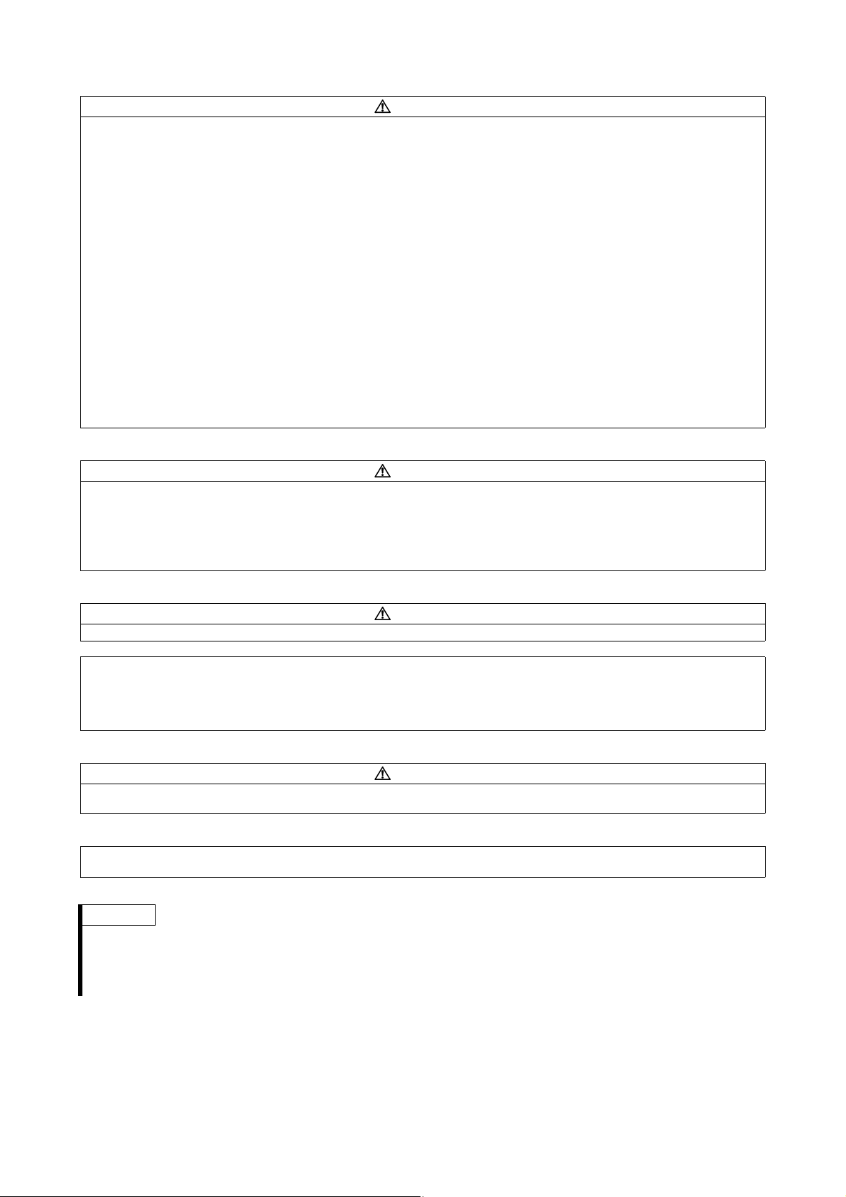
1 PRODUCT DESCRIPTION
LED-Display
4-digit 7-segment display for operational values,
parameter numbers, etc.
Unit Indication
LED to indicate the current unit
앫 Hz: Frequency
앫 A: Current
앫 Off: Voltage
앫 Flicker: Set frequency
Operation Status Display
Lit or flicker during inverter operation
앫 RUN is lit: Forward rotation
앫 RUN flickering slowly: Reverse rotation
앫 RUN flickering fast: Start command is given but the
frequency command is missing
Monitor Indication
Lit to indicate the monitoring mode.
Parameter Setting Mode
Lit to indicate the parameter setting mode.
Operation Mode Indication
LED to indicate the operation mode
앫 PU operation mode (PU)
앫 External operation mode (EXT)
앫 Network operation mode (NET)
앫 Combined operation mode (PU and EXT)
1.1 FR-D700 SC Inverter
An FR-D700 SC frequency inverter is a device that converts the fixed voltage and frequency of the mains power supply into a variable
voltage with a variable frequency. It is installed between the mains supply and the motor and makes continuously-variable speed
adjustment possible.
The adjustable frequency AC drive generates the rotational energy of the motor, which in turn generates the torque of the motor.
It controls induction motors for a variety of automation applications such as air conditioning, conveyor, washing machine, machine
tools, lift machines, etc.
1.2 Operation Panel
NOTE
For detailed description of the operation panel please refer to the "Inverter FR-D700 SC Instruction Manual".
1
Page 8

2 INSTALLATION OF THE INVERTER AND INSTRUCTIONS
FR - D740 - 036 SC - EC
FR-D740-036SC-EC
FR-D740-036SC-EC
Symbol Voltage Class
D720S Single-phase 200 V class
D740 Three-phase 400 V class
Symbol Type Number
008
to
160
3-digit display
Capacity plate example
Rating plate example
Capacity plate
Rating plate
Serial number
Inverter type
Input rating
Output rating
Serial number
Inverter type
Symbol Control Circuit Terminal Specification
SC Source-logic safety stop function model
Serial number description
A 0 X 123456
Product ID and Lot
Month of construction: 1 to 9 for Jan. to Sep., X to Z for Oct. to Dec.
Last digit of year of construction: 0 for 2010 for example
Alphabetical code of revision
DANGER
Unpack the inverter and check the capacity plate on the front cover and the rating plate on the inverter side face to ensure that
the product agrees with your order and the inverter is intact.
2.2 General Precaution
The bus capacitor discharge time is 10 minutes. Before starting wiring or inspection, switch power off, wait for more than 10 minutes,
and check for residual voltage between terminal P/+ and N/– with a meter etc., to avoid a hazard of electrical shock.
2.3 Environment
Before installation, check that the environment meets following specifications:
Ambient temperature –10 °C to +50 °C (non-freezing)
Ambient humidity
Atmos phere
Altitude
Vibra tion
CAUTION
앫 Install the inverter on a strong surface securely and vertically with bolts.
앫 Leave enough clearances and take cooling measures.
앫 Avoid places where the inverter is subjected to direct sunlight, high temperature and high humidity.
앫 Install the inverter on a non-combustible surface.
90 % RH or less (non-condensing)
Indoors (free from corrosive gas, flammable gas, oil mist, dust and dirt)
Maximum 1000 m above sea level for standard operation. After that derate by 3 % for every extra 500 m up to 2500 m (91 %)
5.9 m/s² or less at 10 to 55 Hz (directions of X, Y, Z axes)
2
Page 9
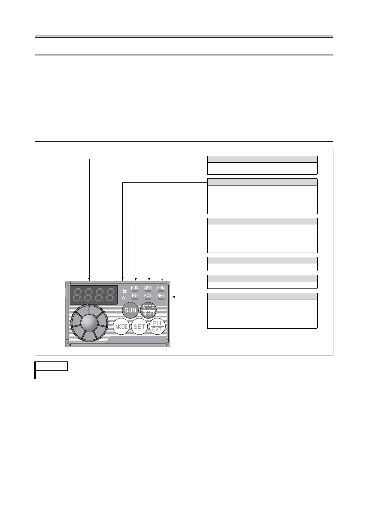
INSTALLATION OF THE INVERTER AND INSTRUCTIONS
Front cover
Wiring cover
Front cover
FR-D720S-008SC to 042SC FR-D720S-070SC and 100SC, FR-D740-012SC to 160SC
Wiring cover
NOTES
앫
When encasing multiple inverters,
install them in parallel and leave
clearance as a cooling measure
.
앫 Install the inverter vertically.
vertical
R
e
f
e
r
t
o
t
h
e
c
l
e
a
r
a
n
c
e
s
b
e
s
i
d
e
Ambient temperature and humidity Clearances (front)Clearances (side)
5 cm 5 cm
5 cm
Inverter
Measurement
position
Measurement
position
Temperature: –10 °C to +50 °C
Humidity: 90 % RH maximum
10 cm or more
1 cm
or more
*1
10 cm or more
1 cm
or more
*1
1 cm
or
more
*1
Leave enough clearances and
take cooling measures.
*1
When using the inverters at the
ambient temperature of 40 °C or less,
the inverters can be installed
closely attached (0 cm clearance).
When ambient temperature exceeds
40 °C, clearances between the inverter
should be 1 cm or more (5 cm or more
for the FR-D740-120SC or more).
*1
5 cm or more for the
FR-D740-120SC or more
Inverter
2.4 Installation of the Inverter
Enclosure surface mounting
Remove the front cover and wiring cover to fix the inverter to the surface.
3
Page 10
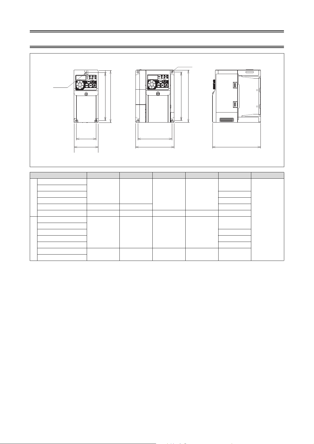
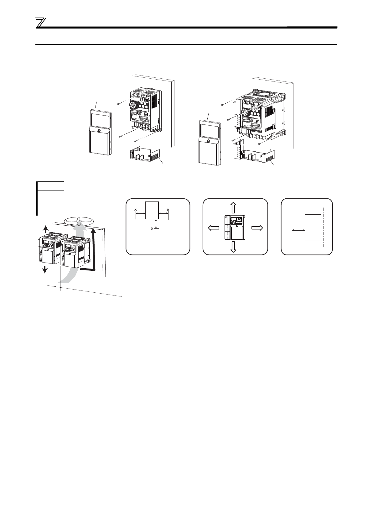
3 OUTLINE DIMENSION DRAWING
W1
W
H1
H
D
W
W1
H1
H
2-ØC hole
1-ØC hole
Inverter Type W W1 H H1 D C
FR-D720S-008SC
FR-D720S-014SC
FR-D720S-025SC 142.5
68 56
128 118
FR-D720S-042SC 162.5
200 V class
FR-D720S-070SC 108 96 155.5
FR-D720S-100SC 140 128 150 138 145
FR-D740-012SC
FR-D740-022SC
FR-D740-036SC 135.5
108 96 128 118
FR-D740-050SC 155.5
FR-D740-080SC 165.5
400 V class
FR-D740-120SC
FR-D740-160SC
220 208 150 138 155
80.5
129.5
(Unit: mm)
5
4
Page 11
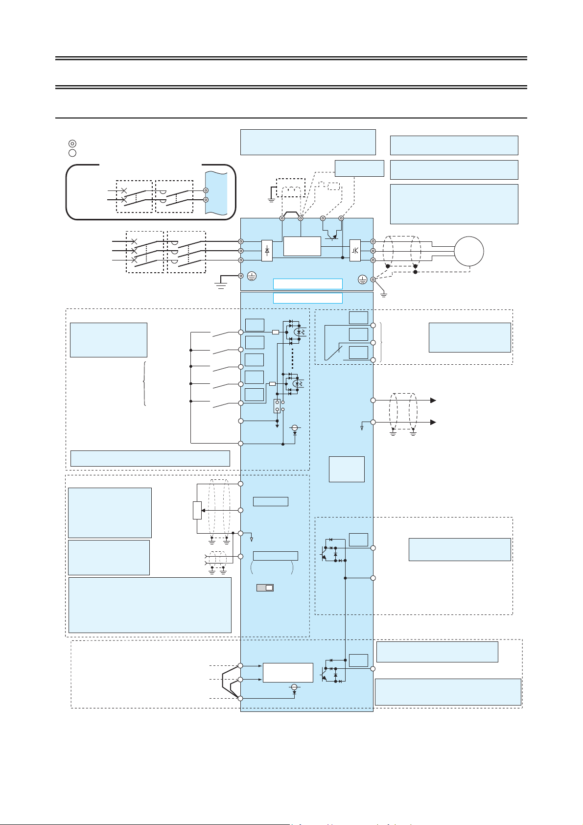
4WIRING
R/L1
P1 P/ +
PR
N/-
S/L2
T/L3
U
V
W
STR
STF
RH
RM
RL
SD
PC
RUN
SE
A
B
C
2
10(+5V)
2
3
1
4
(+)
(-)
5
*4
*1
*8
*2
*3
*5
SINK
SOURCE
VI
*5
AM
5
(+)
(-)
*7
*9
*6
*6
24V
L1
N
S1
S2
SC
SO
24V
Source logic
Main circuit terminal
Control circuit terminal
Jumper
*1 DC reactor
When connecting a DC reactor, remove the
jumper across P1 and P/+.
Earth
Motor
3-phase
AC power
supply
Main circuit
Control circuit
Terminal functions vary with
the input terminal
assignment.
(Pr. 178 to Pr. 182)
Forward
rotation start
Reverse
rotation start
High speed
Medium speed
Low speed
Multi-speed selection
*2 When using terminals PC-SD as a 24 V DC power supply, take
care not to short across terminals PC-SD.
Safety stop input common terminal
Frequency setting signals (analog)
Terminal 4
input
(Current inpu t)
0–5 V DC
0–5 V DC
0–10 V DC
PU
connector
*4 It is recommended to use
a 1 k 2 W potentiometer
when the frequency setting
signal is changed frequently.
Relay output
(Alarm outp ut)
Running
Terminal functions vary by
Pr. 192 "ABC terminal function
selection".
Terminal functions vary with the output
terminal assignment.
(Pr. 190)
Open collector output common
Safety monitor output common
Sink/source common
Frequency
setting
potentiometer
1 k,1/2 W
M
3~
Earth
Brake unit
(Option)
*8 Brake resistor (FR-ABR)
Install a thermal relay to prevent an overheat
and burnout of the brake resistor.
(The brake resistor can not be connected to
the FR-D720S-008SC and 014SC.)
*5 Terminal input specific ations can be changed by analog input
specifications switchover (Pr. 267) (in itial settings in frame).
Set the voltage/current input switch in the "V" position to
select voltage input (0–5 V/0–10 V) and "I" (initial value) to
select current input (0/4–20 mA.)
To use terminal 4 (initial setting is current input), set "4" in any
of Pr.178 to Pr.182 (input terminal function selec tion) to assign
the function, and turn ON AU signal.
Voltage/current
input switch
Relay output
Open collector output
Analog signal output
(0–10 V DC)
0–10 V DC
(Analog common)
4–20 mA DC
*3 Terminal input specifications
can be changed by analog
input specifications switchover (Pr. 73) (initial settings in
frame). Terminal 10 and terminal 2 are used as PTC input
terminal (Pr. 561).
Earth
1-phase
AC power
supply
*7 A brake transistor is not built-in to the
FR-D720S-008SC and 014SC.
Control input signals (no voltage input allowed)
Single-phase power input
Safety stop signal
Safety stop input (Channel 2)
Shorting wire
*6 FR-D720S-008SC to 100SC: +, –
FR-D740-012SC to 160SC: P/+, N/–
MCCB MC
MCCB MC
Inrush
current limit
circuit
Terminal functions vary with the output
terminal assignment. (Pr. 197)
Safety monitor output
*9 Common terminal of terminal SO is terminal SE.
Output shutoff
circuit
Safety stop input (Channel 1)
24 V DC power supply/max. 100 mA load current
Contact input common (Source*)
Contact input common (Sink*),
24 V DC power supply common
*(Common for external power supply transistor)
4.1 Terminal Connection Diagram
5
Page 12
WIRING
Screw size (M3,5)
Jumper
Screw size
(M3,5)
Motor
Power supply
M
3 ~
L1 N
Jumper
Power supply
Screw size
(M4)
Motor
M
3 ~
L1 N
Screw size (M4)
N/-
P/+
Screw size (M4)
Jumper
Screw size
(M4)
Motor
Power supply
M
3 ~
L1L2 L3
N/-
P/+
Jumper
Power supply
Screw size
(M4)
Motor
M
3 ~
L1 L2 L3
Screw size (M4)
CAUTION
앫 To prevent a malfunction due to noise, keep the signal cables more than 10 cm away from the power cables. Also separate the main circuit wire
of the input side and the output side.
앫 After wiring, wire offcuts must not be left in the inverter.
Wire offcuts can cause an alarm, failure or malfunction. Always keep the inverter clean. When drilling mounting holes in a control box etc., take
care not to allow chips and other foreign matter to enter the inverter.
앫 Set the voltage/current input switch in the correct position. An incorrect setting may cause a fault, failure or malfunction.
앫 The output of the single-phase power input specification is three-phase 230 V.
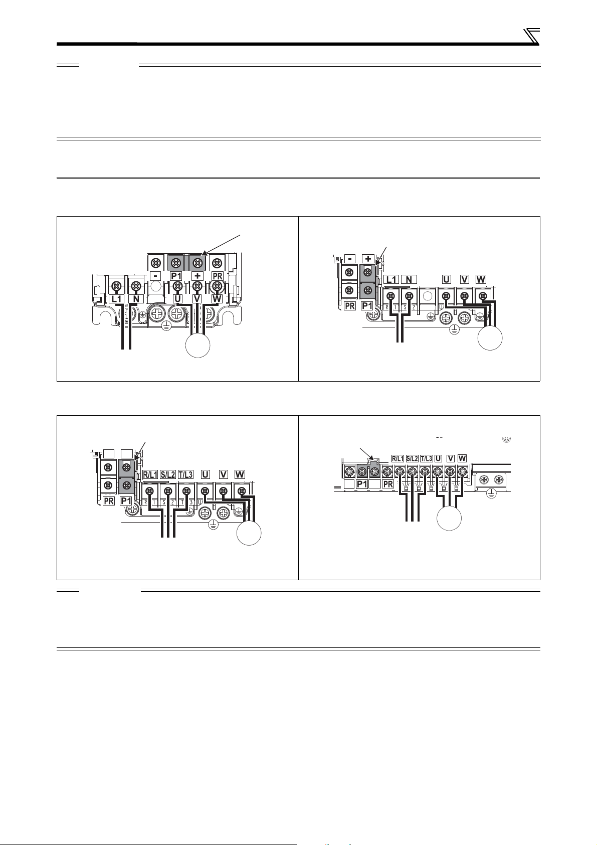
4.2 Main Circuit Terminal Specifications
4.2.1 Terminal Arrangement of the Main Circuit Terminal, Power Supply and the Motor Wiring
Single-Phase 200 V Class
FR-D720S-008SC to 042SC FR-D720S-070SC and 100SC
Three-Phase 400 V Class
FR-D740-012SC to 080SC FR-D740-120SC, 160SC
CAUTION
앫 Make sure the power cables are connected to the R/L1, S/L2, T/L3 (three-phase 400 V class) resp. to the L1, N (for single-phase
200 V class). Never connect the power cable to the U, V, W of the inverter. Doing so will damaged the inverter. (Phase sequence
needs not to be matched.)
앫 Connect the motor to U, V, W. At this time turning on the forward rotation switch (signal) rotates the motor in the clockwise
direction when viewed on the motor shaft.
6
Page 13

WIRING
3wire resistance [m /m wiring distance [m] current [A]
1000
--------------------------------------------------------------------------------------------------------------------------------------------------------------------------------------------
4.3 Cables and Wiring Length
4.3.1 Cable Size
Select the recommended cable size to ensure that a voltage drop will be 2 % max.
If the wiring distance is long between the inverter and motor, a main circuit cable voltage drop will cause the motor torque to
decrease especially at the output of a low frequency.
The following tables indicate a selection example for the wiring length of 20 m.
Single-phase 200 V class (when input power supply is 220 V)
Applicable Inverter Type
Terminal Screw Size
*4
Tightening Torque [Nm]
L1, N, P1, + U, V, W
FR-D720S-008SC to 042SC M3.5 1.2 2-3.5 2-3.5
FR-D720S-070SC M4 1.5 2-4 2-4
FR-D720S-100SC M4 1.5 5.5-4 2-4
Cable Sizes
Applicable Inverter Type
HIV [mm2]
L1, N, P1, + U, V, W
*1
Earth Cable
Gauge
L1, N, P1, + U, V, W L1, N, P1, + U, V, W
AWG
*2
FR-D720S-008SC to 042SC 2 2 2 14 14 2.5 2.5 2.5
FR-D720S-070SC 2 2 2 14 14 2.5 2.5 2.5
FR-D720S-100SC 3.5 2 3.5 12 14 4 2.5 4
Three-phase 400 V class (when input power supply is 440 V)
U, V, W
*4
Tightening Torque [Nm]
*1
Earth Cable
Gauge
Cable Sizes
R/L1, S/L,
T/L3, P/1,
P/+
R/L1, S/L2, T/L3, P/1, P/+ U, V, W
*2
AWG
U, V, W
Applicable Inverter Type
Terminal Screw Size
FR-D740-012SC to 080SC M4 1.5 2-4 2-4
FR-D740-120SC M4 1.5 5.5-4 2-4
FR-D740-160SC M4 1.5 5.5-4 5.5-4
Applicable Inverter Type
R/L1, S/L2,
HIV [mm2]
T/L3, P/1,
P/+
FR-D740-012SC to 080SC 2 2 2 14 14 2.5 2.5 2.5
FR-D740-120SC 3.5 2 3.5 12 14 4 2.5 4
FR-D740-160SC 3.5 3.5 3.5 12 12 4 4 4
*1
The recommended cable size is that of the HIV cable (600 V class 2 vinyl-insulated cable) with continuous maximum permissible temperature of 75 °C. Assumes that
the ambient temperature is 50 °C or less and the wiring distance is 20 m or less.
*2
The recommended cable size is that of the THHW cable with continuous maximum permissible temperature of 75 °C. Assumes that the ambient temperature is
40 °C or less and the wiring distance is 20 m or less.
(Selection example for use mainly in the United States.)
*3
The recommended cable size is that of the PVC cable with continuous maximum permissible temperature of 70 °C. Assumes that the ambient temperature is 40 °C
or less and the wiring distance is 20 m or less.
(Selection example for use mainly in Europe.)
*4
The terminal screw size indicates the terminal size for R/L1, S/L2, T/L3, U, V, W, PR, P/+, N/–, P1 and a screw for earthing.
For single-phase power input, the terminal screw size indicates the size of terminal screw for L1, N, U, V, W, PR, +, –, P1 and a screw for earthing (grounding).
Crimping Terminal
PVC [mm2]
Crimping Terminal
PVC [mm2]
R/L1,S/L2,
T/L3, P/1,
U, V, W
P/+
*3
Earth Cable
Gauge
*3
Earth Cable
Gauge
CAUTION
앫 Tighten the terminal screw to the specified torque. A screw that has been tightened too loosely can cause a short circuit or
malfunction. A screw that has been tightened too tightly can cause a short circuit or malfunction due to the unit breakage.
앫 Use crimping terminals with insulation sleeve to wire the power supply and motor.
The line voltage drop can be calculated by the following expression:
Line voltage drop [V] =
Use a larger diameter cable when the wiring distance is long or when it is desired to decrease the voltage drop (torque reduction)
in the low speed range.
7
Page 14

WIRING
500 m or less
300 m
300 m
300 m + 300 m = 600 m
Motor capacity 0.1 K 0.2 K 0.4 K
Wiring length 20 m 50 m 100 m
4.3.2 Maximum Permissible Motor Wiring Length
The maximum permissible length of the motor cables depends on the capacity of the inverter and the selected carrier frequency.
The lengths in the following table are for unshielded cables. When shielded cables are used divide the values listed in the table
by 2. Note that the values are for the total wiring length – if you connect more than one motor in parallel you must add the lengths
of the individual motor cables.
Single-phase 200 V class
Setting of Pr. 72 PWM Frequency selection
(Carrier Frequency)
1 (1 kHz) or less 200 m 200 m 300 m 500 m 500 m
2 to 15 (2 kHz to 14.5 kHz) 30 m 100 m 200 m 300 m 500 m
008SC 014SC 025SC 042SC 070SC
Three-phase 400 V class
Setting of Pr. 72 PWM Frequency selection
Total wiring length (FR-D720S-070SC or more, FR-D740-080SC or more)
(Carrier Frequency)
1 (1 kHz) or less 200 m 200 m 300 m 500 m 500 m
2 to 15 (2 kHz to 14.5 kHz) 30 m 100 m 200 m 300 m 500 m
012SC 022SC 036SC 050SC 080SC
FR-D720S-
FR-D740-
Note that the motor windings in three-phase AC motors are subject to far more stress when operated via frequency inverters than
with mains operation. The motor must have been approved by the manufacturer for operation on a frequency inverter.
In the PWM type inverter, a surge voltage attributable to wiring constants is generated at the motor terminals. Especially for a 400 V
class motor, the surge voltage may deteriorate the insulation. When the 400 V class motor is driven by the inverter, consider the
following measures:
앫 Use a "400 V class inverter-driven insulation-enhanced motor" and set frequency in Pr. 72 PWM frequency selection according to
wiring length.
Wiring Length
50 m 50 m–100 m 100 m
Carrier frequency 14.5 kHz 8 kHz 2 kHz
앫 Limiting the voltage rise speed of the frequency inverter output voltage (dV/dT):
If the motor requires a rise speed of 500 V/μs or less you must install a filter in the output of the inverter. Please contact your
Mitsubishi Electric dealer for more details.
CAUTION
앫
Especially for long-distance wiring (particularly when employing shielded motor cables), the inverter may be affected by a charging
current caused by the stray capacitances of the wiring, leading to a malfunction of the overcurrent protective function or fast
response current limit function, or stall prevention function or a malfunction or fault of the equipment connected
on the
inverter output side.
When the fast-response current limit function malfunctions, make the function invalid. When stall prevention function misoperates,
increase the stall level. (For Pr. 22 Stall prevention operation level and Pr. 156 Stall prevention operation selection, refer to the
Instruction Manual.)
앫 For details of Pr. 72 PWM frequency selection, refer to the Instruction Manual.
앫 When using the automatic restart after instantaneous power failure function with wiring length exceeding below, select
without frequency search (Pr. 162 = "1", "11"). (Refer to the instruction manual for further information to Pr. 162).
8
Page 15

4.4 Control Circuit Specification
Recommended wire size:
0.3mm
2
to 0.75mm
2
4.4.1 Terminal Assignment
Input Signal Output Signal
Type Terminal Name Type Terminal Name
STF Forward rotation start Relay A, B, C Relay output (alarm output)
Contact input
Reference
point
Frequency
setting
Communication Safety Stop Signal
Type Terminal Name Terminal Name
RS485 — PU connector S1 Safety stop input (Channel 1)
STR Reverse rotation start
RH, RM, RL Multi-speed selection
SD
PC
10 Frequency setting power supply
2 Frequency setting (voltage)
4 Frequency setting (current)
5 Frequency setting common
Contact input common (sink),
24 V DC power supply common
24 V DC power supply, contact
input common (source)
RUN Inverter running
Open collector
Analog output AM Analog voltage output
S2 Safety stop input (Channel 2)
S0
SC Safety stop input terminal common
SE
Safety monitor output
(Open collector output)
Open collector output common
Safety monitor output common
WIRING
NOTE
For detailed description and reference on any input or output signal refer to the "Inverter FR-D700 SC Instruction Manual" and the "Transistorized
Inverter FR-D700 SC Safety stop function Instruction Manual".
4.4.2 Control Circuit Terminal Layout
10 2 5 4
AM
RUN SE S1 S2 SCSO
CBA
SD
STF
PCSDRHRMRL
STR
9
Page 16
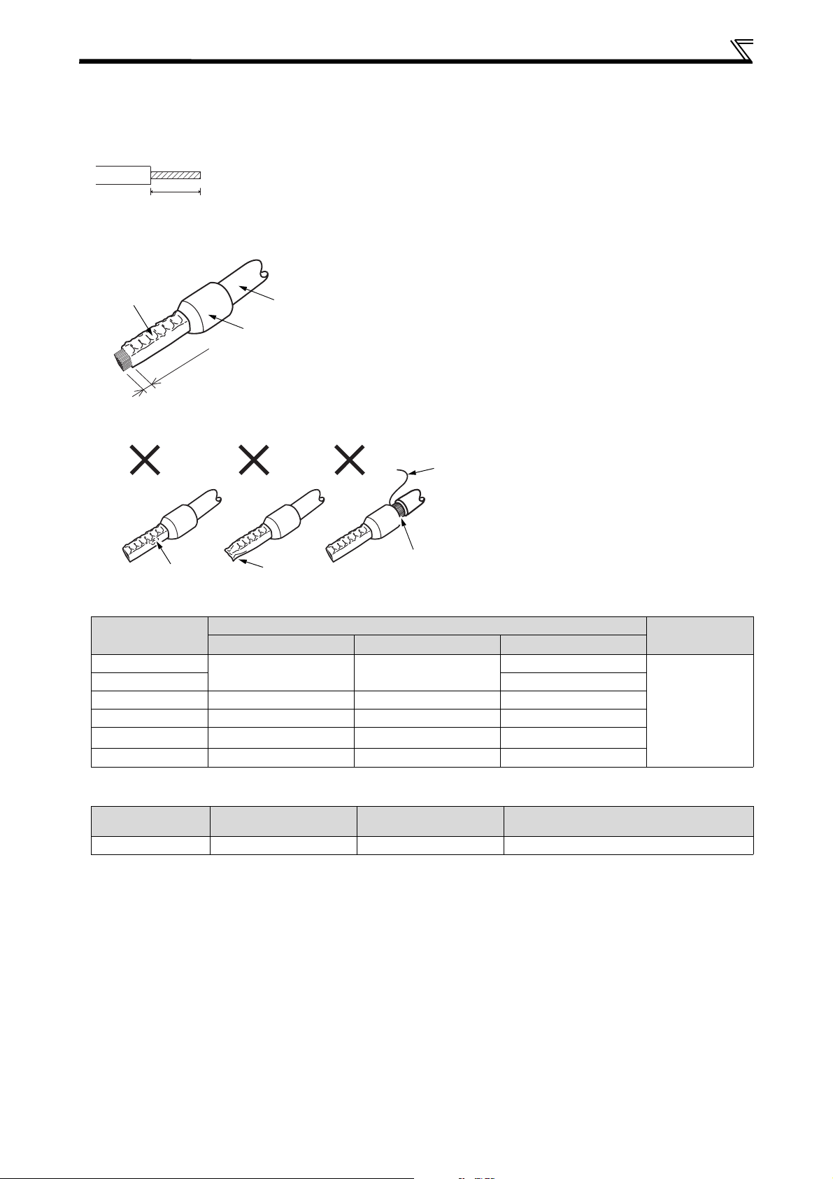
WIRING
10 mm
Shell
0
–
0
,
5
m
m
Cable
Sleeve
Wires are not inserted
into the shell
Crumpled tip
Unstranded
wires
Damaged
4.4.3 Wiring Method
Use a bar terminal and a cable with a sheath stripped off for the control circuit wiring. For a single wire, strip off the sheath of the
cable and apply directly. Insert the bar terminal or the single wire into a socket of the terminal.
앫 Strip off the sheath about the length below. Wire the stripped cable after twisting it to prevent it from becoming loose.
In addition, do not solder it.
앫 Crimp the bar terminal.
Insert wires to a bar terminal, and check that the wires come out for about 0 to 0.5 mm from a sleeve.
앫 Check the condition of the bar terminal after crimping. Do not use a bar terminal of which the crimping is inappropriate, or the
face is damaged.
앫 Introduced products on bar terminals:
Wire Size [mm²]
0.3
0.5 AI 0,5-10WH-GB
With Insulation Sleeve Without Insulation Sleeve
AI 0,5-10WH —
0.75 AI 0,75-10GY A 0,75-10 AI 0,75-10GY-GB
1 AI 1-10RD A 1-10 AI 1-10RD/1000GB
1.25/1.5 AI 1,5-10BK A 1,5-10
0.75 (for two cables)
*1
A bar terminal with an insulation sleeve compatible with MTW wire which has a thick wire insulation
*2
Applicable for terminal ABC
Wire Size [mm²]
AI-TWIN 2 × 0,75-10GY
Bar Terminal
Product Number
0.3 to 0.75 BT 0.75-11 VC 0.75 NH 67 (NICHIFU Co., Ltd.)
Bar Terminal Model
——
Insulation
Product Number
For UL Wire
*1
—
AI 1,5-10BK/1000GB
Bar Terminal Crimping Tool
Bar Terminal
Crimping Tool
CRIMPFOX 6
(Phoenix Contact
Co., Ltd.)
*2
10
Page 17
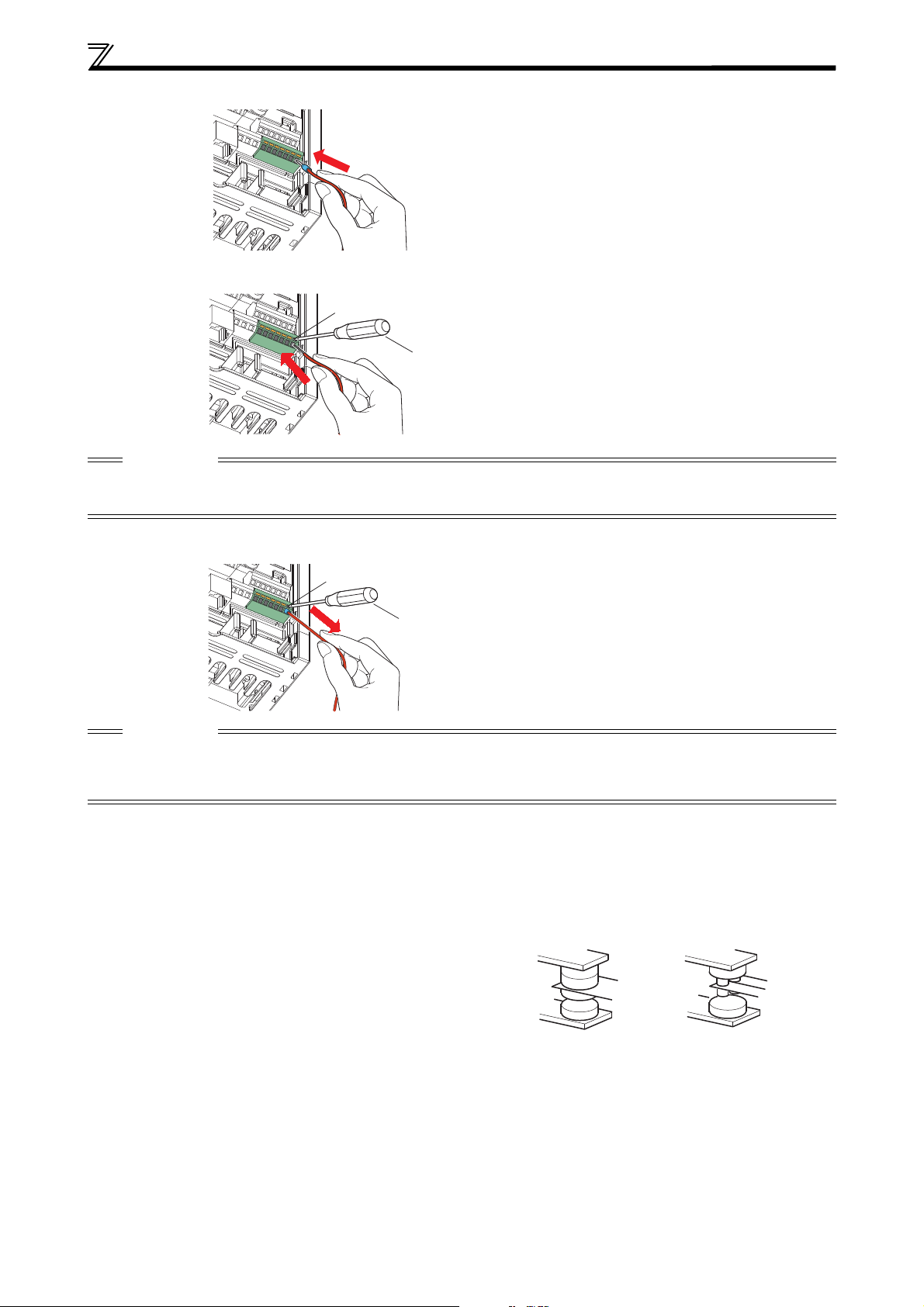
WIRING
Open/close button
Flathead screwdriver
Open/close button
Flathead screwdriver
Micro signal contacts Twin contacts
앫 Insert the wire into a socket.
When using a single wire or a stranded wire without a bar terminal, push an open/close button all the way down with a flathead
screw driver, and insert the wire.
CAUTION
앫 When using a stranded wire without a bar terminal, twist enough to avoid short circuit with a nearby terminals or wires.
앫 Place the flathead screwdriver vertical to the open/close button. In case the blade tip slips, it may cause to damage of inverter
or injury.
Wire removal
앫 Pull the wire with pushing the open/close button all the way down firmly with a flathead screwdriver.
CAUTION
앫 Use a small flathead screwdriver (Tip thickness: 0.4 mm/tip width: 2.5 mm, such as SZF 0-0,4x2,5 (Phoenix Contact Co., Ltd.)). If
a flathead screwdriver with a narrow tip is used, terminal block may be damaged.
앫 Place the flathead screwdriver vertical to the open/close button. In case the blade tip slips, it may cause to damage of inverter
or injury.
4.4.4 Wiring Instructions
앫 Terminals PC, 5, and SE are all common terminals (0 V) for I/O signals and are isolated from each other. Avoid connecting the
terminal PC and 5 and the terminal SE and 5 (ground). Terminal PC is a common terminal for the contact input terminals (STF,
STR, RH, RM and RL).
Use shielded or twisted cables for connection to the control circuit terminals and run them away from the main and power circuits
앫
(including the 230 V relay sequence circuit).
Use two or more parallel micro-signal contacts or twin
앫
contacts to prevent a contact faults when using contact inputs
since the control circuit input signals are micro-currents.
앫
Do not apply a voltage to the contact input terminals (e. g. STF)
of the control circuit.
앫 Always apply a voltage to the alarm output terminals (A, B, C)
via a relay coil, lamp, etc. In no way must a voltage be shortcircuited by these relay contacts.
앫 It is recommended to use the cables of 0.3mm² to 0.75mm² gauge for connection to the control circuit terminals.
The wiring length should be 30 m maximum.
앫 The level of the control signals can be switched over between positive (SOURCE) and negative (SINK) logic. The input signals are
set to source logic when shipped from the factory. To change the control logic, the jumper connector above the control circuit
terminal block must bemoved to the other position.
앫 Do not short terminal PC and SD. Inverter may be damaged.
11
Page 18

WIRING
24 V DC
M
3~
Emergency stop
button
STOP
START
AC Power supply
Motor
Safety relay module
MELSEC QS90SR2SN-Q
CAUTION
4.4.5 Safety Stop Function
Connection Diagram for Intended Use
This diagram shows the example connection diagram for intended use.
The safety relay module is necessary for the generating redundant safe stop signals which are connected to the S1 and S2 terminal
of FR-D700 SC.
To prevent restarting when the failure detected, output terminal of FR-D700 SC, RUN-SE as example in diagram, must be inserted
into reset circuit of safety relay module to disable the RESET button operation.
For detailed configuration please refer to the Instruction manual and the "Transistorized Inverter FR-D700 SC Safety stop function
Instruction Manual"
.
R/L1 S/L2 T/L3
RUN (SAFE2)
SE
STF
STOP
FR-D700SC
+24V X0 X1
24G
COM0 COM1
XS0 XS1 Z10 Z00 Z20
Z11 Z01 Z21
S2
S1
SC
PC
U V W
앫 Ensure the safety relay module and the D700 SC unit is mounted closely in enclosure meeting IP54 and all interconnection
wiring is short and protected against open and short circuit faults.
Refer to ISO/IEC13849-2.
앫
The approved safety relay module to ISO13849-1/EN954-1 safety category 3 or better shall be used in conjunction with FR-D700 SC
as shown in example.
In addition, all other components with in the safety stop loop shall be "safety approved" types.
앫 Combination availability when using the safety stop function
Inverter Model
(Safety stop terminal logic)
FR-D700 EC
(sink logic)
FR-D700 SC EC
(source logic)
FR-E700 SC EC
(source logic)
FR-D700 EC
(sink logic)
FR-D700 SC EC
(source logic)
FR-E700 SC EC
(source logic)
✔ ——
— ✔✔
— ✔✔
12
Page 19

5 PRECAUTIONS FOR USE OF THE INVERTER
The FR-D700 SC series is a highly reliable product, but incorrect peripheral circuit making or operation/handling method may shorten
the product life or damage the product.
Before starting operation, always recheck the following items.
앫 Use crimping terminals with insulation sleeve to wire the power supply and motor.
앫 Application of power to the output terminals (U, V, W) of the inverter will damage the inverter. Never perform such wiring.
앫 After wiring, wire offcuts must not be left in the inverter.
Wire offcuts can cause an alarm, failure or malfunction. Always keep the inverter clean. When drilling mounting holes in a control
box etc., take care not to allow chips and other foreign matter to enter the inverter.
앫 Use cables of the size to make a voltage drop 2 % maximum.
If the wiring distance is long between the inverter and motor, a main circuit cable voltage drop will cause the motor torque to decrease
especially at the output of a low frequency.
Refer to page 7 for the recommended cable size.
앫 The overall wiring length should be within the prescribed length.
Especially for long distance wiring, the fast-response current limit function may be reduced or the equipment connected to the
inverter output side may malfunction or become faulty under the influence of a charging current due to the stray capacity of
the wiring. Therefore, note the overall wiring length. (Refer to page 8)
앫 Electromagnetic Compatibility
Operation of the frequency inverter can cause electromagnetic interference in the input and output that can be propagated by
cable (via the power input lines), by wireless radiation to nearby equipment (e.g. AM radios) or via data and signal lines. Install
an optional filter if present to reduce air propagated interference on the input side of the inverter. Use AC or DC reactors to
reduce line propagated noise (harmonics). Use shielded motor power lines to reduce output noise.
For EMC correct installation refer to the Manual for Frequency Inverters and EMC.
앫 Do not install a power factor correction capacitor, varistor or arrester on the inverter output side. This will cause the inverter to
trip or the capacitor, varistor, or arrester to be damaged. If any of the above devices is installed, immediately remove it.
앫 Before starting wiring or other work after the inverter is operated, wait for at least 10 minutes after the power supply has been
switched off, and check that there are no residual voltage using a tester or the like. The capacitor is charged with high voltage
for some time after power off and it is dangerous.
앫 A short circuit or earth fault on the inverter output side may damage the inverter modules.
–
Fully check the insulation resistance of the circuit prior to inverter operation since repeated short circuits caused by peripheral
circuit inadequacy or an earth fault caused by wiring inadequacy or reduced motor insulation resistance may damage
inverter modules.
– Fully check the to-earth insulation and inter-phase insulation of the inverter output side before power-on.
Especially for an old motor or use in hostile atmosphere, securely check the motor insulation resistance etc.
앫 Do not use the inverter input side magnetic contactor to start/stop the inverter.
Since repeated inrush currents at power ON will shorten the life of the converter circuit (switching life is about 1,000,000 times),
frequent starts and stops of the MC must be avoided.
Always use the start signal (ON/OFF of STF and STR signals) to start/stop the inverter.
앫
Across P/+ and PR terminals, connect only an external regenerative brake discharge resistor. Do not connect a mechanical brake.
The brake resistor can not be connected to the FR-D720S-008SC and 014SC. Leave terminals P/+ and PR open.
Also, never short between P/+ and PR.
the
13
Page 20

PRECAUTIONS FOR USE OF THE INVERTER
Inverter
Undesirable Current
Interlock
Power
supply
M
3~
앫 Do not apply a voltage higher than the permissible voltage to the inverter I/O signal circuits.
Application of a voltage higher than the permissible voltage to the inverter I/O signal circuits or opposite polarity may damage
the I/O devices. Especially check the wiring to prevent the speed setting potentiometer from being connected incorrectly to
short terminals 10-5.
앫
Provide electrical and mechanical interlocks for MC1 and MC2 which are
used for bypass operation.
When the wiring is incorrect or if there is a bypass circuit as shown on
the right, the inverter will be damaged by leakage current from the
power supply due to arcs generated at the time of switch-over or chattering
caused by a sequence error.
If the machine must not be restarted when power is restored after a power
앫
failure, provide a magnetic contactor in the inverter's input side and also make up a sequence which will not switch ON the start
signal.
If the start signal (start switch) remains ON after a power failure, the inverter will automatically restart as soon as the power is
restored.
앫 Inverter input side magnetic contactor (MC)
On the inverter input side, connect a MC for the following purposes. (Refer to the Instruction Manual.)
– To release the inverter from the power supply when a fault occurs or when the drive is not functioning (e. g. emergency stop
operation). For example, MC avoids overheat or burnout of the brake resistor when heat capacity of the resistor is insufficient
or brake regenerative transistor is damaged with short while connecting an optional brake resistor.
– To prevent any accident due to an automatic restart at restoration of power after an inverter stop made by a power failure
– To separate the inverter from the power supply to ensure safe maintenance and inspection work. If using an MC for emergency
stop during operation, select an MC regarding the inverter input side current as JEM1038-AC-3 class rated current.
앫 Handling of inverter output side magnetic contactor
Switch the magnetic contactor between the inverter and motor only when both the inverter and motor are at a stop. When the
magnetic contactor is turned ON while the inverter is operating, overcurrent protection of the inverter and such will activate.
When MC is provided for switching to the commercial power supply, for example, switch it ON/OFF after the inverter and motor
have stopped.
앫 Instructions for overload operation
When performing operation of frequent start/stop of the inverter, increase/decrease in the temperature of the transistor
element of the inverter may repeat due to a continuous flow of large current, shortening the life from thermal fatigue. Since
thermal fatigue is related to the amount of current, the life can be increased by reducing bound current, starting current, etc.
Decreasing current may increase the life. However, decreasing current will result in insufficient torque and the inverter may not
start. Therefore, increase the inverter capacity to have enough allowance for current.
앫 Make sure that the specifications and rating match the system requirements.
앫 When the motor speed is unstable, due to change in the frequency setting signal caused by electromagnetic noises from the
inverter, take the following measures when applying the motor speed by the analog signal.
– Do not run the signal cables and power cables (inverter I/O cables) in parallel with each other and do not bundle them.
– Run signal cables as far away as possible from power cables (inverter I/O cables).
– Use shielded cables as signal cables.
– Install a ferrite core on the signal cable (Example: ZCAT3035-1330 TDK).
14
Page 21
6 FAILSAFE OF THE SYSTEM WHICH USES THE INVERTER
System failure
Controller
Inverter
Sensor
(speed, temperature,
air volume, etc.)
To the alarm detection sensor
When a fault occurs, the inverter trips to output a fault signal. However, a fault output signal may not be output at an inverter fault
occurrence when the detection circuit or output circuit fails, etc. Although Mitsubishi Electric assures best quality products, provide
an interlock which uses inverter status output signals to prevent accidents such as damage to machine when the inverter fails for
some reason.
At the same time consider the system configuration where failsafe from outside the inverter, without using the inverter, is enabled
even if the inverter fails.
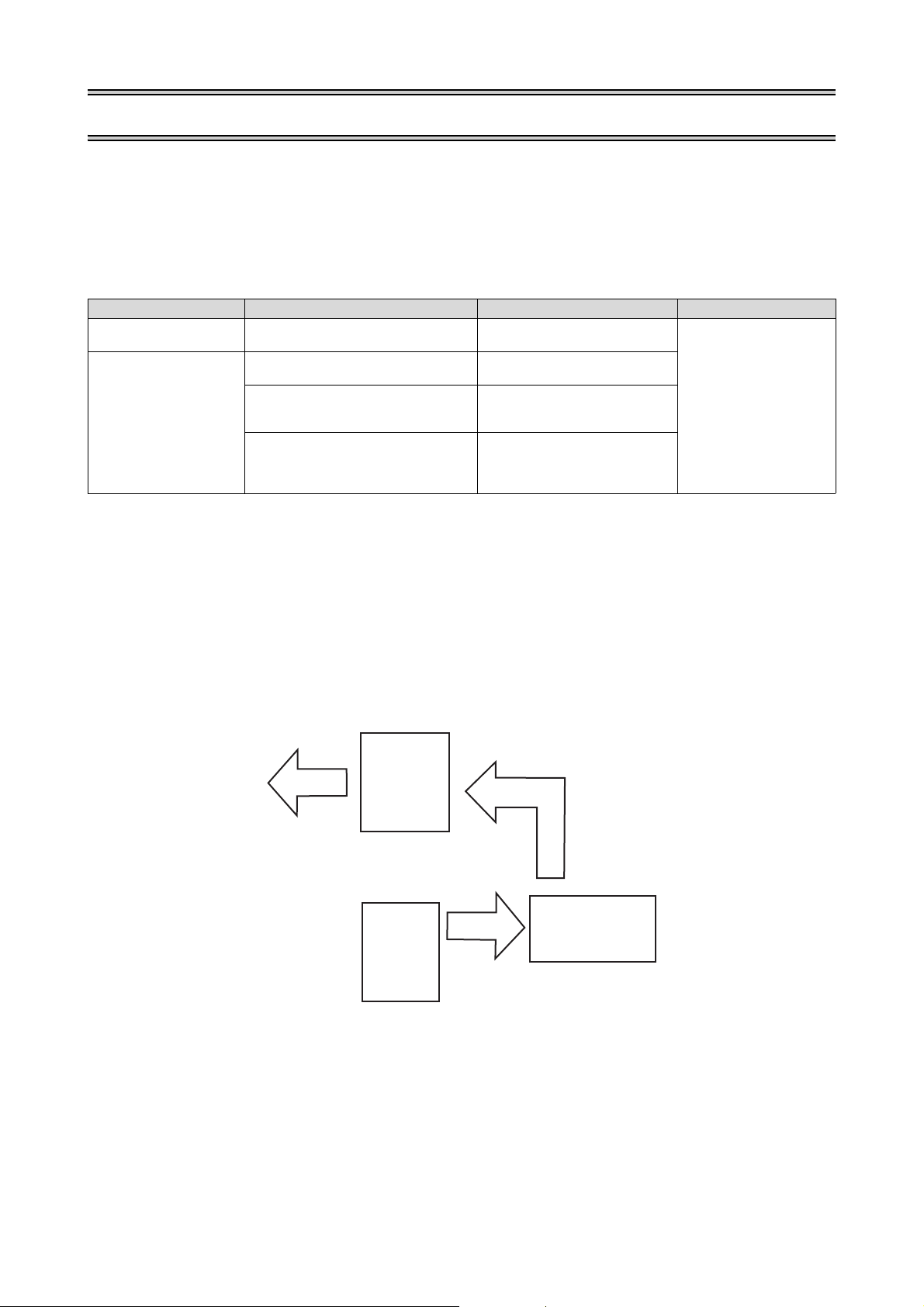
Interlock Method which uses the Inverter Status Output Signals
By combining the inverter status output signals to provide an interlock as shown below, an inverter alarm can be detected.
Interlock Method Check Method Used Signals Refer to
Inverter protective function
operation
Inverter runnning status
Backup Method Outside the Inverter
Even if the interlock is provided by the inverter status signal, enough failsafe is not ensured depending on the failure status of the
inverter itself. For example, even if the interlock is provided using the inverter fault output signal, start signal and RUN signal
output, there is a case where a fault output signal is not output and RUN signal is kept output even if an inverter fault occurs.
Provide a speed detector to detect the motor speed and current detector to detect the motor current and consider the backup
system such as checking up as below according to the level of importance of the system. Check the motor running and motor
current while the start signal is input to the inverter by comparing the start signal to the inverter and detected speed of the speed
detector or detected current of the current detector. Note that the motor current runs as the motor is running for the period until
the motor stops since the inverter starts decelerating even if the start signal turns off. For the logic check, configure a sequence
considering the inverter deceleration time. In addition, it is recommended to check the three-phase current when using the
current detector.
Operation check of an alarm contact
Circuit error detection by negative logic
Operation ready signal check
Logic check of the start signal and
running signal
Logic check of the start signal and
output current
Fault output signal
(ALM signal)
Operation ready signal
(RY signal)
Start signal
(STF signal, STR signal)
Running signal (RUN signal)
Start signal
(STF signal, STR signal)
Output current detection signal
(Y12 signal)
Refer to chapter
of the Instruction Manual
"
Parameter"
Check if there is no gap between the actual speed and commanded speed by comparing the inverter speed command and detected
speed of the speed detector.
15
Page 22
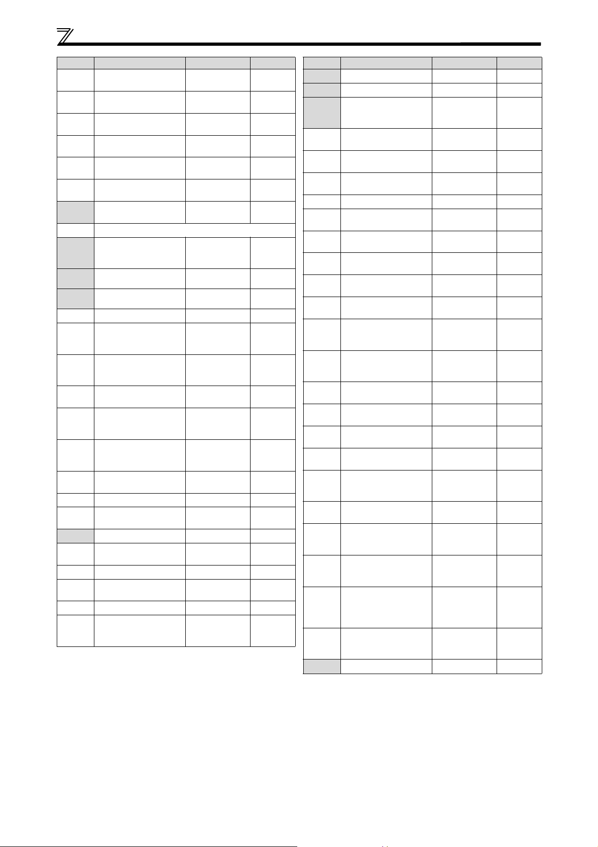
7 PARAMETER
For simple variable-speed operation of the inverter, the initial setting of the parameters may be used. Set the necessary parameters
to meet the load and operational specifications. Parameter setting, change and check can be made from the operation panel. For
details of parameters, refer to the instruction manual.
In the initial setting of Pr. 160 Extended function display selection, simple mode and extended mode parameters are displayed.
Parameter Name
160
Extended function
display selection
Initial
Val ue
0
NOTES
앫 The parameters marked are the simple mode parameters.
앫 The parameters marked with in the table allow its setting to be changed during operation even if "0" (initial
value) is set in Pr. 77 Parameter write selection.
Setting
Range
9999 Only the simple mode parameters can be displayed.
Remarks
0 Simple mode and extended mode parameters can be displayed.
Parame ter
0
1
2
3
4
5
6
7
8
9
10
11
12
13
14
15
16
Name Setting Range Initial Value
Torque boost
Maximum frequency
Minimum frequency
Base frequency
Multi-speed setting
(high speed)
Multi-speed setting
(middle speed)
Multi-speed setting
(low speed)
Acceleration time
Deceleration time
Electronic thermal
O/L relay
DC injection brake
operation frequency
DC injection brake
operation time
DC injection brake
operation voltage
Starting frequency
Load pattern selection
Jog frequency
Jog acceleration/
deceleration time
0 to 30 %
0 to 120 Hz 120 Hz
0 to 120 Hz 0 Hz
0 to 400 Hz 50 Hz
0 to 400 Hz 50 Hz
0 to 400 Hz 30 Hz
0 to 400 Hz 10 Hz
0 to 3600 s
0 to 3600 s
0 to 500 A
0 to 120 Hz 3 Hz
0 to 10 s 0.5 s
0 to 30 %
0 to 60 Hz 0.5 Hz
0 to 3 0
0 to 400 Hz 5 Hz
0 to 3600 s 0.5 s
6/4/3 % *
5 s/10 s *
5 s/10 s *
Rated
inverter
current
6/4 % *
3
1
2
2
Parameter
17
18
19
20
22
23
24 to 27
29
30
31
32
33
34
35
36
Name Setting Range Initial Value
MRS input selection
High speed maximum
frequency
Base frequency
voltage
Acceleration/
deceleration
reference frequency
Stall prevention
operation level
Stall prevention
operation level
compensation factor
at double speed
Multi-speed setting 4
speed to 7 speed
Acceleration/
deceleration
pattern selection
Regenerative function
selection
Frequency jump 1A
Frequency jump 1B
Frequency jump 2A
Frequency jump 2B
Frequency jump 3A
Frequency jump 3B
0, 2, 4 0
120 to 400 Hz 120 Hz
0 to 1000 V, 8888,
9999
1 to 400 Hz 50 Hz
0 to 200 % 150 %
0 to 200 %, 9999
0 to 400 Hz, 9999 9999
0, 1, 2 0
0, 1, 2 0
0 to 400 Hz, 9999
8888
9999
9999
9999
9999
9999
9999
9999
*1
Differs according to capacities.
6 %: FR-D720S-042SC or less, FR-D740-022SC or less
4 %: FR-D720S-070SC and 100SC, FR-D740-036SC to 080SC
3 %: FR-D740-120SC and 160SC
*2
Differs according to capacities.
5 s: FR-D720S-008SC to 100SC, FR-D740-080SC or less
10 s: FR-D740-120SC and 160SC
*3
Differs according to capacities.
6 %: FR-D720S-008SC and 014SC
4 %: FR-D720S-025SC and 100SC, FR-D740-012SC to 160SC
16
Page 23
PAR AM ET ER
Parame ter
37
40
41
42
43
44
45
46
47
48
51
52
55
56
57
58
59
60
65
66
67
68
69
Name Setting Range Initial Value
Speed display
RUN key rotation
direction selection
Up-to-frequency
sensitivity
Output frequency
detection
Output frequency
detection for reverse
rotation
Second acceleration/
deceleration time
Second deceleration
time
Second torque boost
Second V/F
(base frequency)
Second stall
prevention
operation current
Second electronic
thermal O/L relay
DU/PU main display
data selection
Frequency monitoring
reference
Current monitoring
reference
Restart coasting time
Restart cushion time
Remote function
selection
Energy saving control
selection
Retry selection
Stall prevention
operation reduction
starting frequency
Number of retries at
alarm occurrence
Retry waiting time
Retry count display
erase
0, 0.01 to 9998 0
0, 1 0
0 to 100 % 10 %
0 to 400 Hz 6 Hz
0 to 400 Hz, 9999 9999
0 to 3600 s
0 to 3600, 9999 9999
0 to 30 %, 9999 9999
0 to 400 Hz, 9999 9999
0 to 200 %, 9999 9999
0 to 500 A, 9999 9999
0, 5, 8 to 12, 14,
20, 23 to 25,
52 to 55, 61, 62,
64, 100
0 to 400 Hz 50 Hz
0 to 500 A
0, 0.1 to 5 s, 9999 9999
0 to 60 s 1 s
0, 1, 2, 3 0
0, 9 0
0 to 5 0
0 to 400 Hz 50 Hz
0 to 10,
101 to 110
0.1 to 600s 1s
00
5 s/10
0
Rated
inverter
current
0
*1
Parameter
70
71
72
73
74
75
77
78
79
80
82
83
84
90
96
117
118
119
120
121
122
123
124
125
126
127
Name Setting Range Initial Value
Special regenerative
brake duty
Applied motor
PWM frequency
selection
Analog input selection
Input filter time
constant
Reset selection/
disconnected PU
detection/PU stop
selection
Parameter write
selection
Reverse rotation
prevention selection
Operation mode
selection
Motor capacity
Motor excitation
current
Motor rated voltage
Rated motor
frequency
Motor constant (R1)
Auto tuning
setting status
PU communication
station number
PU communication
speed
PU communication
stop bit length
PU communication
parity check
Number of PU
communication retries
PU communication
check time interval
PU communication
waiting time setting
PU communication CR/
LF presence/absence
selection
Terminal 2 frequency
setting gain frequency
Terminal 4 frequency
setting gain frequency
PID control automatic
switchover
frequency
0 to 30 % 0 %
0, 1, 3, 13, 23, 40,
43, 50, 53
0 to 15 1
0, 1, 10, 11 1
0 to 8 1
0 to 3, 14 to 17 14
0, 1, 2 0
0, 1, 2 0
0, 1, 2, 3, 4, 6, 7 0
0.1 to 7.5 kW,
9999
0 to 500 A,
9999
0 to 1000 V
10 to 120 Hz 50 Hz
0 to 50 ,
9999
0, 11, 21 0
0 to 31
(0 to 247)
48, 96, 192, 384 192
0, 1, 10, 11 1
0, 1, 2 2
0 to 10, 9999 1
0, 0.1 to 999.8 s,
9999
0 to 150 ms, 9999 9999
0, 1, 2 1
0 to 400 Hz 50 Hz
0 to 400 Hz 50 Hz
0 to 400 Hz, 9999 9999
0
9999
9999
200 V/
400 V
9999
0
0
*2
*1
Differs according to capacities.
5 s: FR-D720S-008SC to 100SC, FR-D740-080SC or less
10 s: FR-D740-120SC and 160SC
*2
The initial value differs according to the voltage class:
200 V/400 V
17
Page 24
PARAMETER
Parame ter
128
129
130
131
132
133
134
145
146
150
151
152
153
156
157
158
160
161
162
165
166
167
168
169
170
171
178
Name Setting Range Initial Value
PID action selection
PID proportional band
PID integral time
PID upper limit
PID lower limit
PID action set point
PID differential time
PU display language
selection
Parameter for manufacturer setting. Do not set.
Output current
detection level
Output current
detection signal
delay time
Zero current
detection level
Zero current
detection time
Stall prevention
operation selection
OL signal output timer
AM terminal function
selection
Extended function
display selection
Frequency setting/
key lock operation
selection
Automatic restart
after instantaneous
power failure
selection
Stall prevention
operation level
for restart
Output current
detection signal
retention time
Output current
detection operation
selection
Parameter for manufacturer setting.
Do not set.
Watt-hour meter clear
Operation hour
meter clear
STF terminal function
selection
0, 20, 21,
40 to 43
0.1 to 1000 %,
9999
0.1 to 3600 s,
9999
0 to 100 %,
9999
0 to 100 %,
9999
0 to 100 %,
9999
0.01 to 10 s, 9999 9999
0 to 7 1
0 to 200 % 150 %
0 to 10 s 0 s
0 to 200 % 5 %
0 to 1 s 0.5 s
0 to 31, 100, 101 0
0 to 25 s, 9999 0 s
1 to 3, 5, 8 to 12,
14, 21, 24, 52, 53,
61, 62
0, 9999 0
0, 1, 10, 11 0
0, 1, 10, 11 1
0 to 200 % 150 %
0 to 10 s,
9999
0, 1 0
0, 10, 9999 9999
0, 9999 9999
0 to 5, 7, 8, 10, 12,
14, 16, 18, 24, 25,
37, 60, 62, 65 to
67, 9999
0
100 %
1 s
9999
9999
9999
1
0.1 s
60
Parameter
179
180
181
182
190
192
197
232
to
239
240
241
244
245
246
247
249
250
251
255
256
Name Setting Range Initial Value
STR terminal function
selection
RL terminal function
selection
RM terminal function
selection
RH terminal function
selection
RUN terminal function
selection
ABC terminal function
selection
SO terminal function
selection
Multi-speed setting
(speeds 8 to 15)
Soft-PWM operation
selection
Analog input display
unit switchover
Cooling fan operation
selection
Rated slip
Slip compensation
time constant
Constant-power range
slip compensation
selection
Earth (ground) fault
detection at start
Stop selection
Output phase loss
protection selection
Life alarm status
display
Inrush current
suppression circuit life
display
0 to 5, 7, 8, 10, 12,
14, 16, 18, 24, 25,
37, 61, 62, 65 to
67, 9999
0 to 5, 7, 8, 10, 12,
14, 16, 18, 24, 25,
37, 62, 65 to 67,
9999
0, 1, 3, 4, 7, 8, 11
to 16, 25, 26, 46,
47, 64, 70, 80, 81,
90, 91, 93, 95, 96,
98, 99, 100, 101,
103, 104, 107,
108, 111 to 116,
125, 126, 146,
147, 164, 170,
180, 181, 190,
191, 193, 195,
196, 198, 199,
9999
0, 1, 3, 4, 7, 8, 11
to 16, 25, 26, 46,
47, 64, 70, 80, 81,
90, 91, 95, 96, 98,
99, 100, 101, 103,
104, 107, 108, 111
to 116, 125, 126,
146, 147, 164,
170, 180, 181,
190, 191, 195,
196, 198, 199,
9999
0, 1, 3, 4, 7, 8, 11
to 16, 25, 26, 46,
47, 64, 70, 80, 81,
90, 91, 93, 95, 96,
98, 99, 100, 101,
103, 104, 107,
108, 111 to 116,
125, 126, 146,
147, 164, 170,
180, 181, 190,
191, 193, 195,
196, 198, 199
0 to 400 Hz, 9999 9999
0, 1 1
0, 1 0
0, 1 1
0 to 50 %, 9999 9999
0.01 to 10 s 0.5 s
0, 9999 9999
0, 1 0
0 to 100 s,
1000 to 1100 s,
8888, 9999
0, 1 1
(0 to 15) 0
(0 to 100 %) 100 %
61
0
1
2
0
99
80
9999
18
Page 25
PAR AM ET ER
Parame ter
257
258
259
260
261
267
268
269
295
296
297
298
299
338
339
340
342
343
450
495
496
502
503
504
549
551
Name Setting Range Initial Value
Control circuit
capacitor life display
Main circuit capacitor
life display
Main circuit capacitor
life measuring
PWM frequency
automatic switchover
Power failure stop
selection
Terminal 4 input
selection
Monitor decimal digits
selection
Parameter for manufacturer setting. Do not set.
Magnitude of
frequency change
setting
Password lock level
Password lock/unlock
Frequency search gain
Rotation direction
detection selection at
restarting
Communication
operation command
source
Communication speed
command source
Communication
startup mode
selection
Communication
EEPROM write
selection
Communication error
count
Second applied motor
Remote output
selection
Remote output data 1
Stop mode selection at
communication error
Maintenance timer
Maintenance timer
alarm output set time
Protocol selection
PU mode operation
command source
selection
(0 to 100 %) 100 %
(0 to 100 %) 100 %
0, 1 (2, 3, 8, 9) 0
0, 1 0
0, 1, 2 0
0, 1, 2 0
0, 1, 9999 9999
0, 0.01, 0.10, 1.00,
10.00
1 to 6, 101 to 106,
9999
1000 to 9998
(0 to 5, 9999)
0 to 32767, 9999 9999
0, 1, 9999 0
0, 1 0
0, 1, 2 0
0, 1, 10 0
0, 1 0
0, 1, 9999 9999
0, 1, 10, 11 0
0 to 4095 0
0,1, 2 0
0 (1 to 9998) 0
0 to 9998, 9999 9999
0, 1 0
2, 4, 9999 9999
0
9999
9999
0
Parameter
555
556
557
561
563
564
571
575
576
577
592
593
594
595
596
597
611
653
665
*1
872
882
883
885
886
888
Name Setting Range Initial Value
Current average time
Data output mask time
Current average value
monitor signal output
reference current
PTC thermistor
protection level
Energization time
carrying-over times
Operating time
carrying-over times
Holding time at a start
Output interruption
detection time
Output interruption
detection level
Output interruption
cancel level
Traverse function
selection
Maximum amplitude
amount
Amplitude
compensation amount
during deceleration
Amplitude
compensation amount
during acceleration
Amplitude
acceleration time
Amplitude
deceleration time
Acceleration time at a
restart
Speed smoothing
control
Regeneration
avoidance frequency
gain
Input phase loss
protection selection
Regeneration
avoidance operation
selection
Regeneration
avoidance operation
level
Regeneration
avoidance
compensation
frequency limit value
Regeneration
avoidance voltage
gain
Free parameter 1
0.1 to 1 s 1 s
0 to 20 s 0 s
0 to 500 A
0.5 to 30 k,
9999
(0 to 65535) 0
(0 to 65535) 0
0.0 to 10.0 s, 9999 9999
0 to 3600 s, 9999 1 s
0 to 400 Hz 0 Hz
900 to 1100 % 1000 %
0, 1, 2 0
0 to 25 % 10 %
0 to 50 % 10 %
0 to 50 % 10 %
0.1 to 3600 s 5 s
0.1 to 3600 s 5 s
0 to 3600 s,
9999
0 to 200 % 0
0 to 200 % 100
0, 1 1
0, 1, 2 0
300 to 800 V
0 to 10 Hz,
9999
0 to 200 % 100 %
0 to 9999 9999
Rated
inverter
current
9999
9999
400 V/
780 V DC
6 Hz
*2
*1
Available only for the three-phase power input specification model.
*2
The initial value differs according to the voltage class:
200 V/400 V
19
Page 26

PARAMETER
Parame ter
889
891
C1
*1
(901)
C2
*1
(902)
C3
*1
(902)
125
*1
(903)
C4
*1
(903)
C5
*1
(904)
C6
*1
(904)
Name Setting Range Initial Value
Free parameter 2
Cumulative power
monitor digit shifted
times
AM terminal
calibration
Terminal 2 frequency
setting bias frequency
Terminal 2 frequency
setting bias
Terminal 2 frequency
setting gain frequency
Terminal 2 frequency
setting gain
Terminal 4 frequency
setting bias frequency
Terminal 4 frequency
setting bias
0 to 9999 9999
0 to 4, 9999 9999
0 to 400 Hz 0 Hz
0 to 300 % 0 %
0 to 400 Hz 50 Hz
0 to 300 % 100 %
0 to 400 Hz 0 Hz
0 to 300 % 20 %
Parameter
126
*1
(905)
C7
*1
(905)
C22
*1
(922)
C23
*1
(922)
C24
*1
(923)
C25
*1
(923)
990
991
Pr.CL
ALLC
Er.CL
Pr.CH
Name Setting Range Initial Value
Terminal 4 frequency
setting gain frequency
Terminal 4 frequency
setting gain
Parameter for manufacturer setting. Do not set.
PU buzzer control
PU contrast
adjustment
Parameter clear
All parameter clear
Alarm history clear
Initial value
change list
0 to 400 Hz 50 Hz
0 to 300 % 100 %
0, 1 1
0 to 63 58
0, 1 0
0, 1 0
0, 1 0
——
*1
The parameter number in parentheses is the one for use with the operation panel (FR-PA02-02) for the FR-E500 series or parameter unit (FR-PU04/FR-PU07).
20
Page 27

8 TROUBLESHOOTING
The frequency inverter FR-D700 SC has a multitude of protective functions which protect the drive and the inverter from damage
in case of a fault. When a fault occurs in the inverter, the protective function is activated bringing the inverter to an alarm stop and
the PU display automatically changes to any of the following fault (alarm) indications.
If the fault does not correspond to any of the following faults or if you have any other problem, please contact your sales
representative.
앫
Retention of fault output signal..... When the magnetic contactor (MC) provided on the input side of the inverter is opened at
the activation of the protective function, the inverter's control power will be lost and the alarm
output will not be held.
앫
Fault or alarm display.........................When a fault or alarm occurs, the operation panel display automatically switches to the fault
or alarm indication.
앫
Resetting method ...............................When a protective function of the inverter is activated, the power output of the inverter is
blocked (motor is coasting). The inverter cannot start up again unless an automatic restart
has been configured or the inverter is reset. Please observe carefully the warnings contained
below in the configuration of an automatic restart or the execution of a reset.
앫 If protective functions were activated (i. e. the inverter switched off with an error message) follow the instructions for error correction
provided in the manual for the inverter. Especially in the case of short circuits or earth contacts in the inverter output and mains
overvoltages the cause of the fault must be determined prior to switching on again as a recurrence of such faults at short intervals can
lead to premature aging of components or even the complete breakdown of the device. After the cause of the fault has been found
and corrected the inverter can be reset and operations continue.
Inverter fault or alarm indications are roughly divided as below.
앫 Error Message
A message regarding operational fault and setting fault by the operation panel and parameter unit (FR-PU04/FR-PU07) is displayed
The inverter does not shut off output.
앫 Warning
The inverter does not shut off output even when a warning is displayed. However, failure to take appropriate measures will lead
to a major fault.
앫 Alarm
The inverter does not shut off output. You can also output an alarm signal by making parameter setting.
앫 Fault
When the protective function is activated, the inverter output is shut off and an fault signal is output.
.
NOTES
앫 For the details of fault displays and other malfunctions, also refer to the Instruction Manual.
앫 Past eight faults can be displayed using the setting dial.
21
Page 28

TROUBLESHOOTING
ON
OFF
RESET
RES
PC
Inverter
CAUTION
8.1 Reset Method of Protective Function
Resetting the Inverter
The inverter can be reset by performing any of the following operations. Note that the internal thermal integrated value of the
electronic thermal relay function and the number of retries are cleared (erased) by resetting the inverter.
Inverter recovers about 1s after reset is cancelled.
Three different methods can be used to reset an inverter.
앫 Using the operation panel, press the STOP/RESET key to reset the inverter.
(This may only be performed when a fault occurs.)
앫 Switch OFF the power once, then switch it ON again after the indicator
of the operation panel turns OFF.
앫 Turn ON the reset signal (RES) for more than 0.1 s. (If the RES signal is kept ON,
"Err." appears (flickers) to indicate that the inverter is in a reset status.)
OFF status of the start signal must be confirmed before resetting the inverter fault. Resetting inverter fault with the start signal
ON restarts the motor suddenly. This may cause injury.
22
Page 29

8.2 List of Alarm Display
to
to
/
TROUBLESHOOTING
Operation Panel Indication Meaning
E - - - Faults history
HOLD Operation panel lock
Er1 to 4 Parameter write error
Error messages
Warnings
LOCD Password locked
Err. Inverter reset
OL Stall Prevention (overcurrent)
oL Stall prevention (overvoltage)
RB Regenerative brake prealarm
Electronic thermal relay function
TH
prealarm
PS PU Stop
MT Maintenance signal output
UV Undervoltage
SA Safety stop
Operation Panel Indication Meaning
E.ILF* Input phase loss
E.OLT Stall prevention
E.BE Brake transistor alarm detection
Output side earth (ground) fault
E.GF
overcurrent protection
E.LF Output phase loss
E.OHT External thermal relay operation
E.PTC* PTC thermistor operation
E.PE Parameter storage device fault
Fau lt
E.PUE PU disconnection
E.RET Retry count excess
E. 5/E.CPU CPU fault
E.CDO*
E.IOH* Inrush current limit circuit fault
Output current detection value
exceeded
Alarm
Fau lt
FN Fan alarm
E.OC1
E.OC2
E.OC3
E.OV1
E.OV2
E.OV3
E.THM
Overcurrent shut-off during
acceleration
Overcurrent shut-off during constant
speed
Overcurrent shut-off during
deceleration or stop
Regenerative overvoltage
shut-off during acceleration
Regenerative overvoltage
shut-off during constant speed
Regenerative overvoltage
shut-off during deceleration or stop
Inverter overload shut-off
E.THT
(electronic thermal relay function)
Motor overload shut-off
(electronic thermal relay function)
E.FIN Fin overheat
* If an E.ILF, E.PTC, E.CDO, E,IOH, E.AIE, or E.SAF fault occurs when using
the FR-PU04, "Fault 14" is displayed on the FR-PU04.
E.AIE* Analog input fault
*
E.SAF
Safety circuit fault
23
Page 30

9 MAINTENANCE AND INSPECTION
CAUTION
CAUTION
9.1 Daily Inspection
Followings are the daily checking points during operation:
앫 Rotation speed of motor
앫 Environmental condition of the inverter drive
앫 Activation of cooling system
앫 Extraordinary vibration or airborne noise
앫 Over heating or discoloration
For detailed checking operation please refer to the Instruction manual of FR-D700 SC.
9.2 Periodic Inspection
It is recommended to make the following checks periodically:
앫 Check for loose screws in the terminal block. Retighten any loose screws.
앫 Check for dust accumulation on the inverter. Clean the heat sink and the cooling fan of the inverter.
앫 Check for unusual noise generated from the inverter. Retighten installation screw.
앫
Check for the operation condition. Keep the operation condition of inverter as written in the Inverter FR-D700 SC Instruction Manual.
앫 For detailed maintenance operation please refer to the Instruction manual of FR-D700 SC.
앫 To avoid an electric shock hazard, insert the magnetic contactor (MC) between AC power supply and FR-D700 SC.
Open the contact of MC and keep away from drive for discharging time (10 minutes) before performing any work on the drive.
And verify that the voltage on the bus capacitors has discharged before Measure the DC bus voltage at the P/+ and N/–
terminals or test points (refer to page 6 "Main circuit terminal specifications" for locations).
The voltage must be zero.
앫 Do not carry out a megger (insulation resistance) test on the control circuit of the inverter. It will cause a failure.
9.3 Checking and Testing of Restart Prevention
To avoid systematic faults, a test even for faulty demands of the safety function has to be performed in order to check the correct
function of the restart prevention.
This test shall be carried out at system installation, any software changes, parameterization changes, and/or at least once per year.
For detailed checking procedure refer to the "Transistorized Inverter FR-D700 SC Safety stop function Instruction Manual".
Any misuse of safety function could lead to personal injury or death, property damage, or economic loss.
To ensure that the system complies fully with requirement of safety, make a system-level risk assessment and adequate verification
for systematic failure.
24
Page 31

10 SPECIFICATIONS
Category of Safe Torque Off Function
The FR-D700 SC adjustable frequency AC drive family is suitable for emergency stop according to EN 60204-1, stop category 0
within safety related applications according to EN954-1 up to safety category 3.
200 V Class
Model FR-D720S-첸첸첸SC-EC 008 014 025 042 070 100
Rated motor capacity [kW]
Output capacity [kVA]
*1
*2
Rated current [A] 0.8 1.4 2.5 4.2 7.0 10.0
Overload current rating
Output
Voltage
*4
Regenerative braking torque
*3
*5
Power supply voltage 1-phase, 200–240 V AC
Voltage range 170–264 V AC at 50/60 Hz
Power supply frequency 50/60 Hz ± 5 %
Rated input capacity [kVA]
Power supply
*6
Protective structure IP20
Cooling system Self cooling Forced air cooling
Weight [kg] 0.5 0.5 0.9 1.1 1.5 2.0
400 V Class
Model FR-D740-첸첸첸SC-EC 012 022 036 050 080 120 160
Rated motor capacity [kW]
Output capacity [kVA]
Rated current [A]
Overload current rating
Output
Voltage
*4
Regenerative braking torque
Power supply voltage 3-phase, 380–480 V AC
Voltage range 325–528 V AC at 50/60 Hz
Power supply frequency 50/60 Hz ± 5 %
Rated input capacity [kVA]
Power supply
Protective structure IP20
Cooling system Self cooling Forced air cooling
Weight [kg] 1.31.31.41.51.53.33.3
*1
*2
*7
*3
*5
*6
0.1 0.2 0.4 0.75 1.5 2.2
0.3 0.6 1.0 1.7 2.8 4.0
200% of rated motor capacity for 0.5s; 150 % for 60 s
3-phase AC, 0 V to power supply voltage
150 % 100 % 50 % 20 %
0.5 0.9 1.5 2.3 4.0 5.2
0.4 0.75 1.5 2.2 3.7 5.5 7.5
0.91.72.73.86.19.112.2
1.2
(1.4)
2.2
(2.6)
3.6
(4.3)
5.0
(6.0)
8.0
(9.6)
12.0
(14.4)
16.0
(19.2)
200% of rated motor capacity for 0.5 s; 150% for 60 s
3-phase AC, 0 V to power supply voltage
100 % 50 % 20 %
1.5 2.5 4.5 5.5 9.5 12 17
*1
The applied motor capacity indicated is the maximum capacity applicable for use of the Mitsubishi Electric 4-pole standard motor.
*2
The rated output capacity indicated assumes that the output voltage is 230 V/440 V (200 V class/400 V class).
*3
The % value of the overload current rating indi cated is the ratio of the overload current to the inverter’s rated output current (ambient temperature of 50 °C for 400 V
class). For repeated duty, allow time for the inverter and motor to return to or below the temperatures under 100 % load.
*4
The maximum output voltage does not exceed the power supply voltage. The maximum output voltage can be changed within the setting range. However, the
pulse voltage value of the inverter output side voltage remains unchanged at about 2
*5
The braking torque indicated is a short-duration average torque (which varies with motor loss) when the motor alone is decelerated from 60 Hz in the shortest time
and is not a continuous regenerative torque. When the motor is decelerated from the frequency higher than the base frequency, the average deceleration torque will
reduce. Since the inverter does not contain a brake resistor, use the optional brake resistor when regenerative energy is large. A brake unit (FR-BU2) may also be used.
*6
The power supply capacity varies with the value of the power supply side inverter impedance (including those of the input reactor and cables).
*7
When operating the inverter with ambient temperature of 40 °C maximum, the rated output current is the value in parentheses.
that of the power supply.
25
Page 32

A APPENDIX
A.1 Instructions for Compliance with the EU Directives
The EU Directives are issued to standardize different national regulations of the EU Member States and to facilitate free movement
of the equipment, whose safety is ensured, in the EU territory.
Since 1996, compliance with the EMC Directive that is one of the EU Directives has been legally required. Since 1997, compliance
with the Low Voltage Directive, another EU Directive, has been also legally required. When a manufacturer confirms its equipment
to be compliant with the EMC Directive and the Low Voltage Directive, the manufacturer must declare the conformity and affix
the CE marking.
앫 The authorized representative in the EU
Name: Mitsubishi Electric Europe B.V.
Address: Gothaer Strasse 8, 40880 Ratingen, Germany
NOTE
We declare that this inverter, when equipped with the dedicated EMC filter, conforms with the EMC Directive in industrial
environments and affix the CE marking on the inverter. When using the inverter in a residential area, take appropriate measures
and ensure the conformity of the inverter used in the residential area.
A.1.1 EMC Directive
We declare that this inverter, when equipped with the EMC Directive compliant EMC filter, conforms with the EMC Directive and
affix the CE marking on the inverter.
앫 EMC Directive: 2004/108/EC
앫 Standard(s): EN61800-3:2004 (Second environment/PDS Category "C3")
NOTES
앫 First environment
Environment including residential buildings. Includes building directly connected without a transformer to the low voltage
power supply network which supplies power to residential buildings.
앫 Second environment
Environment including all buildings except buildings directly connected without a transformer to the lower voltage power
supply network which supplies power to residential buildings.
NOTES
앫 Set the EMC Directive compliant EMC filter to the inverter. Insert line noise filters and ferrite cores to the power and control
cables as required.
앫 Connect the inverter to an earthed power supply.
앫 Install a motor, the EMC Directive compliant EMC filter, and a control cable according to the instructions written in the EMC
Installation Guidelines (BCN-A21041-204). (Please contact your sales representative for the EMC Installation Guidelines.)
앫 The cable length between the inverter and the motor is 5 m maximum.
앫 Confirm that the final integrated system with the inverter conforms with the EMC Directive.
26
Page 33
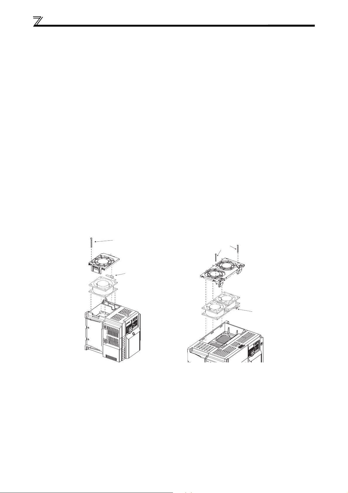
APPENDIX
Fan cover
fixing screws
Fan c over
Fan
Example for FR-D740-036SC
Example for FR-D740-160SC
Fan connec tor
Fan cover fixing screw
Fan cover
Fan
Fan connec tor
FR-D720S-070SC and 100SC, FR-D740-080SC or less FR-D740-120SC or more
A.1.2 Low Voltage Directive
We have self-confirmed our inverters as products compliant to the Low Voltage Directive (conforming standard EN 61800-5-1) and
placed the CE mark on the inverters.
Outline of Instructions
앫
If your application requires by installation standards an RCD (residual current device) as up stream protection please select according
to DIN VDE 0100-530 as following:
Single phase inverter type A or B
Three phase inverter only type B.
–
Additionally, when selecting a residual current device (RCD), leakage current caused by the mains filter, the length of the shielded
motor cable and the carrier frequency must be taken into consideration.
– When connecting AC current using switches without a step function, brief asymmetrical loads may result in unwanted
triggering of the residual current device (RCD). It is recommendable here to use a Type B residual current device (RCD) Type B
with delayed actuation or to switch on all three phases simultaneously using a main contactor.
앫 If you do not use a residual current operated protectice device, provide double or reinfo
other equipment, or put a transformer between the main power supply and inverter.
앫
Do not use a residual current operated protective device (RCD) as an electric shock protector without connecting the equipment
to the earth. Connect the equipment to the earth securely.
앫 Wire the earth terminal independently. (Do not connect two or more cables to one terminal.)
앫 Use the cable sizes on page 7 under the following conditions.
– Ambient temperature: 40 °C maximum
– If conditions are different from above, select appropriate wire according to EN 60204 ANNEX C TABLE 5.
앫
Use a tinned (plating should not include zinc) crimping terminal to connect the earth cable. When tightening the screw, be careful
not to damage the threads.
앫 For use as a product compliant with the Low Voltage Directive, use PVC cable whose size is indicated on page 8.
앫 Use the moulded case circuit breaker and magnetic contactor which conform to the EN or IEC Standard.
앫 Use the inverter under the conditions of overvoltage category II (usable regardless of the earth (ground) condition of the power
supply), overvoltage category III (usable with the earthed-neutral system power supply, 400 V class only) specified in IEC664.
앫 To use the inverter under the conditions of pollution degree 3, install it in the enclosure of IP54 or higher.
앫 To use the inverter (IP20) outside of an enclosure in the enviroment of pollution degree 2, fix a fan cover with the fan cover
fixing srews enclosed.
rced insulation between the inverter and
앫 On the input and output of the inverter, use cables of the type and size set forth in EN 60204 Appendix C.
앫 The operating capacity of the relay outputs (terminal symbols A, B, C) should be 30 V DC, 0.3 A. (Relay outputs are basically
isolated from the inverter internal circuit.)
앫 Control circuit terminals on page 5 are safely isolated from the main circuit.
27
Page 34
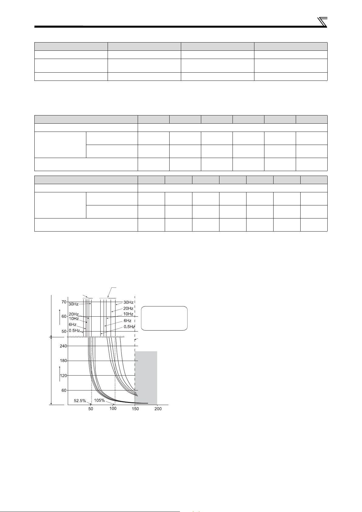
APPENDIX
앫 Operation region
Region on the right of
characteristic curve
앫 Non-operation region
Region on the left of
characteristic curve
Characteristic when electronic
thermal relay function for motor
protection is turned OFF
(Pr. 9 = 0 (A))
Region for
transistor
protection
Inverter output current (%)
(% to the rated inverter current)
Pr. 9 = 100 % setting of
inverter rating
*2
Pr. 9 = 50 % setting of
inverter rating
*1, 2
or more
*3
Operation time [s] Operation time [min]
[s] unit display in this region
[min] unit display
in this region
or more
*3
Environment
During Operation In Storage During Transportation
Ambient temperature –10 °C to +50 °C –20 °C to +65 °C –20 °C to +65 °C
Ambient humidity
90 % RH or less
(non condensing)
Maximum altitude 1000 m 1000 m 10000 m
Wiring protection
Select a UL and cUL certified fuse with Class T fuse equivalent cut-off speed or faster with the appropriate rating for branch circuit
protection, or a UL489 molded case circuit breaker (MCCB) in accordance with the tables below.
FR-D720S-SC-EC (C) 008 014 025 042 070 100
Rated fuse voltage [V] 240 V or more
Without power factor
Fuse maximum
allowable rating [A] *
Molded case circuit breaker (MCCB)
Maximum allowable rating [A] *
improving reactor
With power factor
improving reactor
FR-D740-SC-EC (C) 012 022 036 050 080 120 160
Rated fuse voltage [V] 480 V or more
Without power factor
Fuse maximum
allowable rating [A] *
improving reactor
With power factor
improving reactor
Molded case circuit breaker (MCCB)
Maximum allowable rating [A] *
* Maximum allowable rating by US National Electrical Code. Exact size must be chosen for each installation.
15 20 20 30 40 60
15 20 20 20 30 50
15 15 15 20 25 40
6 101520304070
6 101015253560
15 15 15 15 20 30 40
90 % RH or less
(non condensing)
90 % RH or less
(non condensing)
Motor Overload Protection
The frequency inverters FR-D700 SC are equipped with a UL certified internal electronic thermal relay function.
When using the electronic thermal relay as motor overload protection, set the rated motor current to Pr. 9
Electronic thermal O/L relay
Electronic thermal relay function operation characteristic
This function detects the overload (overheat) of the motor,
stops the operation of the inverter's output transistor, and
stops the output.
When using the Mitsubishi Electric constant-torque motor
set "1" or any of "13", "50" or "53" in Pr. 71. This provides
a 100 % continuous torque characteristic in the low-speed
range. Set the rated current of the motor in Pr. 9.
*1
When 50 % of the inverter rated output current (current value)
is set in Pr. 9.
*2
The % value denotes the percentage to the inverter rated output
current. It is not the percentage to the motor rated current.
*3
When you set the electronic thermal relay function dedicated
to the Mitsubishi Electric constant-torque motor, this characteristic
curve applies to operation at 6 Hz or higher.
.
28
Page 35

APPENDIX
CAUTION
앫
Protective function by electronic thermal relay function is reset by inverter power reset and reset signal input. Avoid unnecessary
reset and power-OFF.
앫 Install an external thermal relay (OCR) between the inverter and a motor when operating several motors by one inverter, or
when using a multi-pole motor or special motor. In this case, set 0A to the electronic thermal O/L relay setting of the inverter.
For the external thermal relay, determine the setting value in consideration of the current indicated on the motor's rating plate
and the line-to-line leakage current. Self-cooling ability of a motor is reduced at low speed operation. Use a motor with a builtin thermal protector.
앫 When the difference between the inverter and motor capacities is large and the setting is small, the protective characteristics
of the electronic thermal relay function will be deteriorated. In this case, use an external thermal relay.
앫 A special motor cannot be protected by the electronic thermal relay function. Use an external thermal relay.
A.1.3 Short Circuit Ratings
앫 200 V class
Suitable for use in a circuit capable of delivering not more than 5 kA rms symmetrical amperes, 264 V Maximum.
앫 400 V class
Suitable for use in a circuit capable of delivering not more than 5 kA rms symmetrical amperes, 528 V Maximum.
29
Page 36
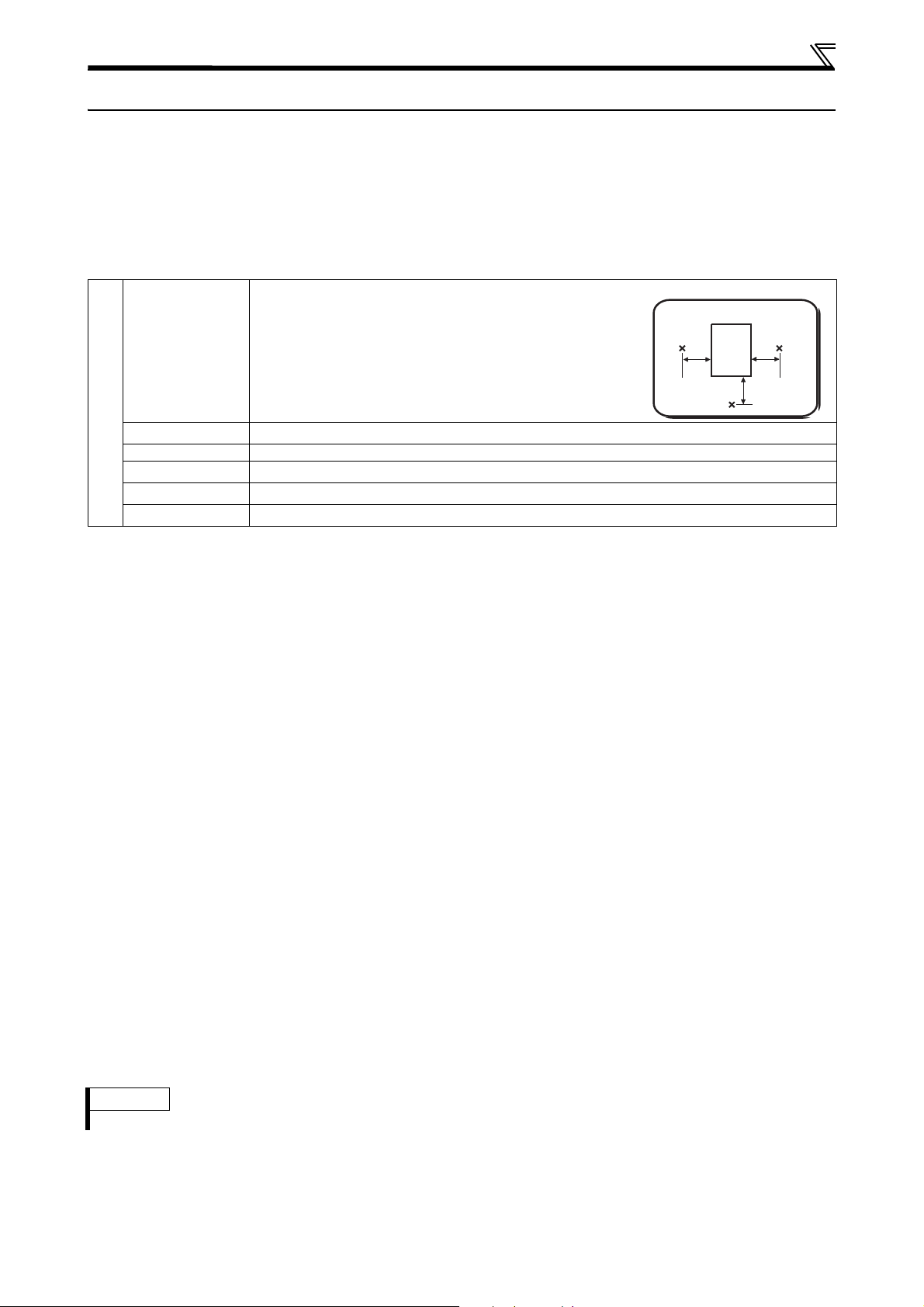
APPENDIX
Inverter
x = Measurement position
A.2 Instructions for UL and cUL
(UL 508C, CSA C22.2 No.14)
A.2.1 General Precaution
The bus capacitor discharge time is 10 minutes. Before starting wiring or inspection, switch power off, wait for more than 10 minutes,
and check for residual voltage between terminal P/+ and N/ with a meter etc., to avoid a hazard of electrical shock.
A.2.2 Environment
Before installation, check that the environment meets following specifications:
Enclosure
Ambient
temperature *
Ambient humidity
Environment
Storage temperature –20 °C to +65 °C
Atmosphere
Altitude
Vibration
* Temperature measured at a measurement position in an enclosure.
–10 °C to +50 °C (non-freezing)
90 % RH or less (non-condensing)
Indoors (free from corrosive gas, flammable gas, oil mist, dust and dirt)
Maximum 1000 m above sea level
5.9 m/s² or less at 10 to 55 Hz (directions of X, Y, Z axes)
5 cm
5 cm
5 cm5 cm
5 cm5 cm
A.2.3 Installation
According to the UL certification the frequency inverters FR-D700 SC have been approved as products for use in enclosure.
Design an enclosure so that the inverter ambient temperature, humidity and atmosphere satisfy the specifications of the above table.
Wiring protection
For installation in the United States, branch circuit protection must be provided in accordance with the National Electrical Code
and any applicable provincial codes.
For installation in Canada, branch circuit protection must be provided in accordance with the Canada Electrical Code and any applicable
provincial codes.
As specified, UL Class T fuses or any faster acting fuse with the appropriate rating or Listed UL 489 Molded Case Circuit Breaker
(MCCB) must be employed. (Refer to page 28)
A.2.4 Short Circuit Ratings
앫 200 V class
Suitable for use in a circuit capable of delivering not more than 100 kA rms symmetrical amperes, 264 V Maximum.
앫 400 V class
Suitable for use in a circuit capable of delivering not more than 100 kA rms symmetrical amperes, 528 V Maximum.
A.2.5 Wiring
For wiring the input (L1, N, R/L1, S/L2, T/L3) and output (U, V, W) terminals of the inverter, use the UL listed copper, stranded wires
(rated at 75 °C) and round crimping terminals. Crimp the crimping terminals with the crimping tool recommended by the terminal
maker.
A.2.6 Motor Overload Protection
The frequency inverters FR-D700 SC are equipped with a UL certified internal electronic thermal relay function.
When using the electronic thermal relay as motor overload protection, set the rated motor current to Pr. 9 Electronic thermal O/L
relay. (Refer to page 28)
NOTE
앫 Safety stop function is not certified by UL.
30
Page 37

APPENDIX
31
Page 38
HEADQUARTERS
MITSUBISHI ELECTRIC
German Branch
Gothaer Straße 8
D-40880 Ratingen
Phone: +49 (0)2102 / 486-0
Fax: +49 (0)2102 / 486-1120
Czech Branch
Avenir Business Park, Radlická 714/113a
CZ-158 00 Praha 5
Phone: +420 - 251 551 470
Fax: +420 - 251-551-471
French Branch
25, Boulevard des Bouvets
F-92741 Nanterre Cedex
Phone: +33 (0)1 / 55 68 55 68
Fax: +33 (0)1 / 55 68 57 57
Irish Branch
Westgate Business Park, Ballymount
IRL-Dublin 24
Phone: +353 (0)1 4198800
Fax: +353 (0)1 4198890
Italian Branch
Viale Colleoni 7
I-20041 Agrate Brianza (MB)
Phone: +39 039 / 60 53 1
Fax: +39 039 / 60 53 312
Poland Branch
Krakowska 50
PL-32-083 Balice
Phone: +48 (0)12 / 630 47 00
Fax: +48 (0)12 / 630 47 01
52, bld. 3 Kosmodamiansk
RU-115054 Мoscow
Phone: +7 495 721-2070
Fax: +7 495 721-2071
Spanish Branch
Carretera de Rubí 76-80
E-08190 Sant Cugat del Vallés (Barcelona)
Phone: 902 131121 // +34 935653131
Fax: +34 935891579
UK Branch
Travellers Lane
UK-Hatfield, Herts. AL10 8XB
Phone: +44 (0)1707 / 27 61 00
Fax: +44 (0)1707 / 27 86 95
Office Tower “Z” 14 F
8-12,1 chome
Tokyo 104-6212
Phone: +81 3 622 160 60
Fax: +81 3 622 160 75
500 Corporate Woods Parkway
Vernon Hills, IL 60061
Phone: +1 847 478 21 00
Fax: +1 847 478 22 53
aya nab 8 floor
, Harumi Chuo-Ku
EUROPEMITSUBISHI ELECTRIC EUROPE B.V.
CZECH REP.MITSUBISHI ELECTRIC EUROPE B.V.-org.sl.
FRANCEMITSUBISHI ELECTRIC EUROPE B.V.
IRELANDMITSUBISHI ELECTRIC EUROPE B.V.
POLANDMITSUBISHI ELECTRIC EUROPE B.V.
EUROPEAN REPRESENTATIVES
Wiener Straße 89
AT-2500 Baden
Phone: +43 (0)2252 / 85 55 20
Fax: +43 (0)2252 / 488 60
Oktyabrskaya 19, Off. 705
BY-220030 Minsk
Phone: +375 (0)17 / 210 46 26
Fax: +375 (0)17 / 210 46 26
Culliganlaan 3
BE-1831 Diegem
Phone: +32 (0)2 / 717 64 30
Fax: +32 (0)2 / 717 64 31
Woluwelaan 31
BE-1800 Vilvoorde
Phone: +32 (0)2 / 257 02 40
Fax: +32 (0)2 / 257 02 49
Aleja Lipa 56
BA-71000 Sarajevo
Phone: +387 (0)33 / 921 164
ITALYMITSUBISHI ELECTRIC EUROPE B.V.
Fax: +387 (0)33 / 524 539
4, Andrei Ljapchev Blvd., PO Box 21
BG-1756 Sofia
Phone: +359 (0)2 / 817 6000
Fax: +359 (0)2 / 97 44 06 1
Losinjska 4 a
HR-10000 Zagreb
Phone: +385 (0)1 / 36 940 - 01/ -02/ -03
Fax: +385 (0)1 / 36 940 - 03
RUSSIAMITSUBISHI ELECTRIC EUROPE B.V.
Technologická 374/6
CZ-708 00 Ostrava-Pustkovec
Phone: +420 595 691 150
Fax: +420 595 691 199
SPAINMITSUBISHI ELECTRIC EUROPE B.V.
Lykkegårdsvej 17
DK-4000 Roskilde
Phone: +45 (0)46/ 75 76 66
Fax: +45 (0)46 / 75 56 26
Pärnu mnt.160i
UKMITSUBISHI ELECTRIC EUROPE B.V.
EE-11317 Tallinn
Phone: +372 (0)6 / 51 81 40
Fax: +372 (0)6 / 51 81 49
Peltoie 37
FIN-28400 Ulvila
JAPANMITSUBISHI ELECTRIC CORPORATION
Phone: +358 (0)207 / 463 540
Fax: +358 (0)207 / 463 541
5, Mavrogenous Str.
GR-18542 Piraeus
Phone: +30 211 / 1206 900
USAMITSUBISHI ELECTRIC AUTOMATION, Inc.
Fax: +30 211 / 1206 999
Fertő utca 14.
HU-1107 Budapest
Phone: +36 (0)1 / 431-9726
Fax: +36 (0)1 / 431-9727
Ritausmas iela 23
LV-1058 Riga
Phone: +371 (0)784 / 2280
Fax: +371 (0)784 / 2281
Savanoriu Pr. 187
LT-02300 Vilnius
Phone: +370 (0)5 / 232 3101
Fax: +370 (0)5 / 232 2980
EUROPEAN REPRESENTATIVES
AUSTRIAGEVA
BELARUSTECHNIKON
BELGIUMESCO DRIVES & AUTOMATION
BELGIUMKoning & Har tman b.v.
BOSNIA AND HERZEGOVINAINEA RBT d.o.o.
BULGARIAAKHNATON
CROATIAINEA RBT d.o.o.
CZECH REPUBLICAutoCont C.S. s.r.o.
DENMARKBeijer Electronics A/S
ESTONIABeijer Electronics Eesti OÜ
FINLANDBeijer Electronics OY
HUNGARYMELTRADE Kft.
LITHUANIABeijer Electronics UAB
99, Paola Hill
Malta- Paola PLA 1702
Phone: +356 (0)21 / 697 816
Fax: +356 (0)21 / 697 817
bld. Traian 23/1
MD-2060 Kishinev
Phone: +373 (0)22 / 66 4242
Fax: +373 (0)22 / 66 4280
Wolweverstraat 22
NL-2984 CD Ridderkerk
Phone: +31 (0)180 – 46 60 04
Fax: +31 (0)180 – 44 23 55
Haarlerbergweg 21-23
NL-1101 CH Amsterdam
Phone: +31 (0)20 / 587 76 00
Fax: +31 (0)20 / 587 76 05
Postboks 487
NO-3002 Drammen
Phone: +47 (0)32 / 24 30 00
Fax: +47 (0)32 / 84 85 77
R. João Francisco do Casal 87/89
PT - 3801-997 Aveiro, Esgueira
Phone: +351 (0)234 / 303 900
Fax: +351 (0)234 / 303 910
Aleea Lacul Morii Nr. 3
RO-060841 Bucuresti, Sector 6
Phone: +40 (0)21 / 430 40 06
Fax: +40 (0)21 / 430 40 02
Izletnicka 10
SER-113000 Smederevo
Phone: +381 (0)26 / 615 401
Fax: +381 (0)26 / 615 401
Jána Derku 1671
SK-911 01 Trencín
Phone: +421 (0)32 743 04 72
Fax: +421 (0)32 743 75 20
Kúpelná 1/A
SK-080 01 Prešov
Phone: +421 (0)51 7580 611
Fax: +421 (0)51 7580 650
Stegne 11
SI-1000 Ljubljana
Phone: +386 (0)1 / 513 8116
Fax: +386 (0)1 / 513 8170
GREECEUTECO
Box 426
SE-20124 Malmö
Phone: +46 (0)40 / 35 86 00
Fax: +46 (0)40 / 93 23 01
Im Schörli 5
CH-8600 Dübendorf
Phone: +41 (0)44 / 802 28 80
Fax: +41 (0)44 / 802 28 28
LATVIABeijer Electronics SIA
Bayraktar Bulvari Nutuk Sok. No:5
TR-34775 Yukarı Dudullu-Ümraniye-İSTANBUL
Phone: +90 (0)216 526 39 90
Fax: +90 (0)216 526 3995
4-B, M. Raskovoyi St.
UA-02660 Kiev
Phone: +380 (0)44 / 494 33 55
Fax: +380 (0)44 / 494-33-66
MALTAALFATRADE Ltd.
MOLDOVAINTEHSIS srl
NETHERLANDSHIFLEX AUTOM.TECHNIEK B.V.
NETHERLANDSKoning & Hartman b.v.
NORWAYBeijer Electronics AS
PORTUGALFonseca S.A.
ROMANIASirius Trading & Services srl
SERBIAINEA RBT d.o.o.
SLOVAKIASIMAP s.r.o.
SLOVAKIAPROCONT, spol. s r.o. Prešov
SLOVENIAINEA RBT d.o.o.
SWEDENBeijer Electronics AB
SWITZERLANDOmni R ay AG
TURKEYGTS
UKRAINECSC Automation Ltd.
EURASIAN REPRESENTATIVES
Ul. Zhambyla 28
KAZ-100017 Karaganda
Phone: +7 7212 / 50 10 00
Fax: +7 7212 / 50 11 50
KAZAKHSTANTOO Kazpromavtomatika
MIDDLE EAST REPRESENTATIVE
23 Al-Saad-Al-Alee St.
EG-Sarayat, Maadi, Cairo
Phone: +20 (0) 2 / 235 98 548
Fax: +20 (0) 2 / 235 96 625
Rehov Hamerkava 19
IL-58851 Holon
Phone: +972 (0)3 / 559 54 62
Fax: +972 (0)3 / 556 01 82
Cebaco Center/Block A Autostrade DORA
Lebanon - Beirut
Phone: +961 (0)1 / 240 430
Fax: +961 (0)1 / 240 438
AFRICAN REPRESENTATIVE
Private Bag 2016
ZA-1600 Isando
Phone: + 27 (0)11 / 977 0770
Fax: + 27 (0)11 / 977 0761
SOUTH AFRICACBI Ltd.
EGYPTI.C. SYSTEMS LTD.
ISRAELSHERF Motion Techn. Ltd.
LEBANONCEG INTERNATIONAL
Mitsubishi Electric Europe B.V. /// FA - European Business Group /// Gothaer Straße 8 /// D-40880 Ratingen /// Germany
Tel.: +49(0)2102-4860 /// Fax: +49(0)2102-4861120 /// info@mitsubishi-automation.com /// www.mitsubishi-automation.com
 Loading...