

Mitsubishi FR-D720-15K, FR-D720-0.4K, FR-D720-0.75K, FR-D720-2.2K, FR-D720-5.5K Instruction Manual
...
INVERTER
1
2
3
4
5
6
7
8
9
10
FR-D700 INSTRUCTION MANUAL (BASIC)
1
FR-D720-0.1K to 15K
FR-D740-0.4K to 15K
FR-D720S-0.1K to 2.2K
2
FR-D710W-0.1K to 0.75K
Thank you for choosing this Mitsubishi Electric Inverter.
This Instruction Manual (Basic) provides handling information and precautions for use of the equipment.
Please forward this Instruction Manual (Basic) to the end user.
CONTENTS
OUTLINE ...................................................................................1
INSTALLATION AND WIRING ...................................................5
PRECAUTIONS FOR USE OF THE INVERTER.........................19
FAILSAFE OF THE SYSTEM WHICH USES THE INVERTER ...22
DRIVING THE MOTOR.............................................................23
ENERGY SAVING OPERATION FOR FANS AND PUMPS ........31
PARAMETERS .........................................................................32
TROUBLESHOOTING ..............................................................36
PRECAUTIONS FOR MAINTENANCE AND INSPECTION ........41
SPECIFICATIONS ....................................................................43
To obtain the Instruction Manual (Applied) and the
Safety stop function instruction manual
Contact where you purchased the inverter, your Mitsubishi Electric sales
representative, or the nearest Mitsubishi Electric FA Center for the
following manuals:
Instruction Manual (Applied) [IB(NA)-0600366ENG]
Safety stop function instruction manual [BCN-A211508-000]
These manuals are required if you are going to utilize functions and
performance.
The PDF manuals are also available for download at the Mitsubishi
Electric FA Global Website (URL: http://www.MitsubishiElectric.co.jp/fa/).
700
3
4
5
6
7
8
9
10
This Instruction Manual (Basic) provides handling information and precautions for use of this product.
WARNING
CAUTION
CAUTION
WARNING
CAUTION
CAUTION
CAUTION
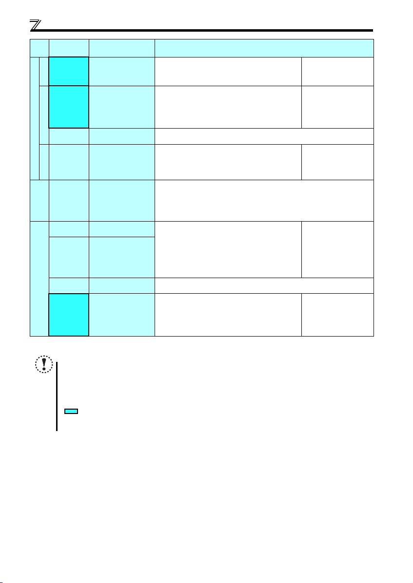
Environment
Surrounding
air
temperature
-10°C to +50°C (non-freezing)
Ambient
humidity
90%RH or less (non-condensing)
Storage
temperature
-20°C to +65°C
Atmosphere
Indoors (free from corrosive gas, flammable gas,
oil mist, dust and dirt)
Altitude/
vibration
Maximum 1000m
5.9m/s
2
or less at 10 to 55Hz (directions of X, Y, Z
axes)
Please forward this Instruction Manual (Basic) to the end user.
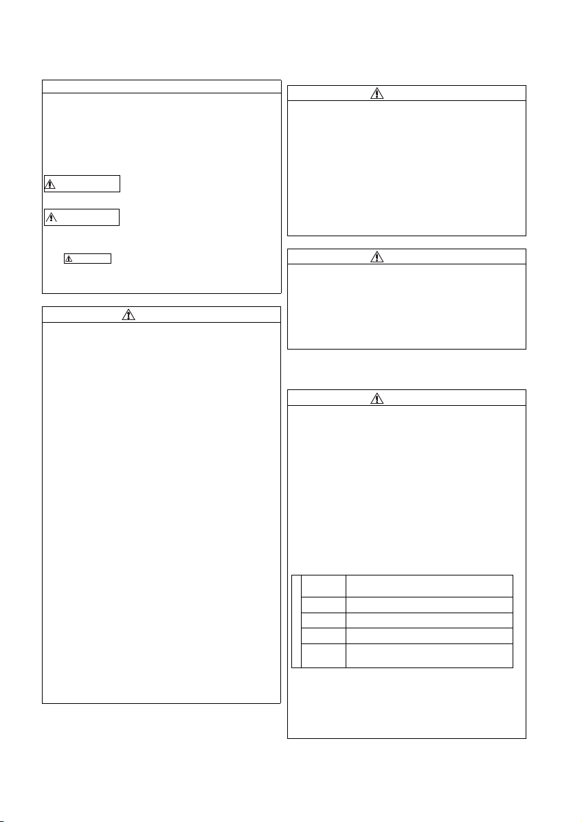
This section is specifically about safety matters
Do not attempt to insta ll, operate, maintain or i nspect this
product until you have read through the Instruction Manual
(Basic) and supplementary documents carefully and can use
the equipment correctly. Do not use this product until you
have a full knowledge of this product mechanism, safety
information and instructions.
In this Instruction Manual (Basic), the safety instruction levels
are classified into "WARNING" and "CAU TION".
Incorrect handling may cause hazardous
conditions, resulting in death or severe
injury.
Incorrect handling may cause hazardous
conditions, resulting in medium or slight
injury, or may cause only material
damage.
The level may even lead to a serious
consequence according to conditions. Both instruction levels
must be followed because these are important to personal
safety.
1. Electric Shock Prevention
While the power of this product is ON, do not remove the
front cover or the wiring cover. Do not run this product with
the front cover or the wiring cover removed. Otherwise you
may access the exposed hig h voltage terminals or the
charging part of the circuitry and get an electric shock.
Even if power is OFF, do not remove the front cover except
for wiring or periodic inspection. You may accidentally
touch the charged inverter circuits and get an electric
shock.
Before wiring or inspection, power must be switched OFF.
To confirm that, LED indication of the operation panel must
be checked. (It must be OFF.) Any person who is involved in
wiring or inspection shall wait for at least 10 minutes after
the power supply has been switched OFF and check that
there are no residual voltage using a tester or the like. The
capacitor is charged with high voltage for some time after
power OFF, and it is dangerous.
This product must be earthed (grounded). Earthing
(grounding) must conform to the requirements of national and
local safety regulations and electrical code (NEC section 250,
IEC 61140 class 1 and other applicable standards).
A neutral-point earthed (grounded) power supply for 400V
class of this product in compliance with EN standard must be
used.
Any person who is involved in wiring or inspection of this
product shall be fully competent to do the work.
This product body must be installed before wiring.
Otherwise you may get an electric shock or be injured.
Do not touch the setting dial or keys with wed hands. Doing
so may cause an electric shock.
Do not subject the cables to scratches, excessive stress,
heavy loads or pinching. Doing so may cause an electric
shock.
Do not change the cooling fan while power is ON, as it is
dangerous.
Do not touch the printed circuit board or handle the cables
with wet hands. Doing so may cause an electric shock.
Never touch the motor terminals, etc. right after powering
OFF as the DC voltage is applied to the motor for 1 second
at powering OFF if the main circuit capacitor capacity is
measured. Doing so may cause an electric shock.
A-1
2. Fire Prevention
This product must be installed on a nonflammable wall
without holes (so that nobody touches the inverter heatsink
on the rear side, etc.). Mounting it to or near flammable
material can cause a fire.
If this product becomes faulty, the product power must be
switched OFF. A continuous flow of large current could
cause a fire.
When using a brake resistor, a sequence that will turn OFF
power when a fault signal is output must be configured.
Otherwise the brake resi stor may overheat due to dam age of
the brake transistor and possibly cause a fire.
Do not connect a resistor directly to the DC terminals P/+
and N/-. Doing so could cause a fire.
Be sure to perform daily and periodic inspections as specified
in the Instruction Manual. If this product is used without
inspection, an explosion, failure, or fire may occur.
3.Injury Prevention
The voltage applied to each terminal must be the ones
specified in the Instruction Manual. Otherwise an explosion
or damage. may occur.
The cables must be connected to the correct terminals.
Otherwise an explosion or damage may occur.
Polarity must be correct. Otherwise an explosion or damage
may occur.
While power is ON or for some time after power-OFF, do not
touch this product since the inverter will be extremely hot.
Doing so can cause burns.
4. Additional Instructions
Also the following points must be noted to prevent an accidental
failure, injury, electric shock, etc.
(1) Transportation and Mounting
Use proper lifting techniques or a trolley when carrying
products. Failure to do so may lead to injuries.
Do not stack the boxes containing this product higher than
the number recommended.
This product must be installed to the position where
withstands the weight of the product according to the
information in the Instruction Manual.
Do not install or operate this product if it is damaged or has
parts missing.
When carrying this product, do not hold it by the front cover
or setting dial; it may fall off or fail.
Do not stand or rest heavy objects on the product.
Ensure the mounting orientation of this product is correct.
Foreign conductive objects must be prevented from
entering this product. That includes screws and metal
fragments or other flammable substance such as oil.
As this product is a precision instrument, do not drop or
subject it to impact.
This product must be used under the following
environment: Otherwise the product may be damaged.
Temperature applicable for a short time, e.g. in transit.
If halogens (including fluorine, chlorine, bromine, and
iodine) contained in fumigants for wood packages enter this
product, the product may be damaged. Prevent the entry of
fumigant residuals or use an alternative method such as
heat disinfection. Note that sterilization or disinfection of
wood packages should be performed before packing the
product.
(2) Wiring
CAUTION
CAUTION
WARNING
CAUTION
CAUTION
CAUTION
CAUTION
CAUTION
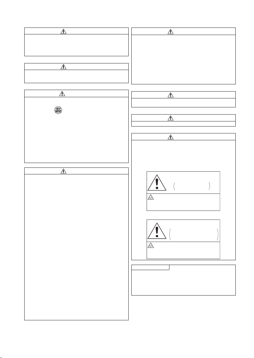
Stay away from the motor and machine.
They will start suddenly (after given
time has elapsed) when alarm occurs.
CAUTION
Retry Function Has
Been Selected
Stay away from the motor and machine.
They will start suddenly (after reset
time has elapsed) when
instantaneous power failure occurs.
CAUTION
Automatic Restart after
Instantaneous Power
Failure Has Been Selected
(5) Emergency stop
Do not install a power factor correction capacitor, surge
absorber, or radio noise filter on the output side of this
product. These devices may overheat or burn out.
The connection orientation of the output cables U, V, W to
the motor affects the rotation direction of the motor.
(3) Trial run
Before starting operation, each parameter must be
confirmed and adjusted. Failure to do so may cause some
machines to make unexpected motions.
(4) Usage
Stay away from the equipment when the retry function is set
as it will restart suddenly after trip.
Since pressing key may not stop output depending on
the function setting status, separate circuit and switch that
make an emergency stop (power OFF, mechanical brake
operation for emergency stop, etc.) must be provided.
OFF status of the start signal must be confirmed before
resetting the inverter fault. Resetting inverter alarm with the
start signal ON restarts the motor suddenly.
The inverter must be used for three-phase induction motors.
Connection of any other electrical equipment to the product
output may damage the equipment.
Do not modify the equipment.
Do not perform parts removal which is not instructed in this
manual. Doing so may lead to fault or damage of t he product.
The electronic thermal relay function does not guarantee
protection of the motor from overheating. It is
recommended to install both an external thermal and PTC
thermistor for overheat protection.
Do not use a magnetic contactor on the inverter input for
frequent starting/stopping of the inverter. Otherwise, the life
of the inverter decreases.
The effect of electromagnetic interference must be reduced
by using an EMC filter or by other means. Otherwise nearby
electronic equipment may be affected.
Appropriate precautions must be taken to suppress
harmonics. Otherwise power supply harmonics from the
inverter may heat/damage the power factor correction
capacitor and generator.
When driving a 400V class motor with the inv erter, the motor
must be an insulation-enhanced motor or measures must be
taken to suppress surge voltage. Otherwise surge voltage,
which is attributed to th e length and thickness o f wire, may
occur at the motor terminals, causing the motor insulation
to deteriorate.
When parameter clear or all parameter clear is performed, the
required parameters must be set again before starting
operations because all parameters return to the initial value.
The inverter can be easily set for high-speed operation.
Before changing its setting, the performances of the motor
and machine must be fully examined.
This product's brake function cannot be used as a
mechanical brake. Use a separate device instead.
Perform an inspection and test operation of this product if it
has been stored for a long period of time.
Static electricity in your body must be discharged before
you touch the product. Otherwise the product may be
damaged.
If you are installing the inverter to drive a three-phase
device while you are contracted for lighting and power
service, consult your electric power supplier.
A safety backup such as an emergency brake must be
provided for devices or equipment in a system to prevent
hazardous conditions in case of failure of this product or an
external device controlling this product.
If the breaker installed on the input side of this product trips,
check for wiring faults (short circuits etc.) and damage to
internal parts of this product. The cause of the trip must be
identified and removed before turning ON the power of the
breaker.
When any protective function is activated, appropriate
corrective action must be taken, and this product must be
reset before resuming operation.
(6) Maintenance, inspection and parts replacement
Do not carry out a megger (insulation resistance) test on the
control circuit of this product. It will cause a failure.
(7) Disposal
This product must be treated as industrial waste.
(8) Application of caution labels
Caution labels are used to ensure safety during use of
Mitsubishi Electric in verters.
Apply the following labels to the inverter if the "retry function"
and/or "automatic restart after instantaneous power failure"
have been enabled.
For the retry function
For automatic restart after instantaneous power failure
General instruction
Many of the diagrams and drawings in this Instruction Manual
(Basic) show the inverter without a cover or partially open for
explanation. Never operate the inverter in this manner. The
cover must be always reinstalled and the instr uction in this
Instruction Manual (Basic) must be followed when operating
the inverter.
A-2
<Abbreviation>
PU: Operation panel and parameter unit (FR-PU04/FR-PU07)
Inverter: Mitsubishi Electric inverter FR-D700 series
FR-D700: Mitsubishi Electric inverter FR-D700 series
Pr.: Parameter number (Number assigned to function)
PU operation: Operation using the PU (operation panel/FR-PU04/FR-PU07)
External operation: Operation using the control circuit signals
Combined operation: Operation using both the PU (operation panel/FR-PU04/FR-PU07) and External operation
Standard motor: SF-JR
Constant torque motor: SF-HRCA
<Trademark>
Company and product names herein are the trademarks and registered trademarks of their respective owners.
<Mark>
REMARKS: Additional helpful contents and relations with other functions are stated.
Note: Contents requiring caution or cases when set functions are not activated are stated.
POINT: Useful contents and points are stated.
<Notes on descriptions in this Instruction Manual>
Connection diagrams in this Instruction Manual appear with the control logic of the input terminals as sink logic, unless
otherwise specified. (For the control logic, refer to page 1.)
<Related document>
Refer to the Instruction Manual (Applied) for further information on the following points.
Removal and reinstallation of the cover
Connection of stand-alone option unit
EMC and leakage currents
Detailed explanation on parameters
Troubleshooting
Check first when you have a trouble
Inspection items (life diagnosis, cooling fan replacement)
Measurement of main circuit voltages, currents and powers
For customers who are replacing the conventional model with this inverter
Harmonic suppression guideline (when inverters are used in Japan)
All models of general-purpose inverters used by specific consumers are covered by "Harmonic Suppression Guidelines for Consumers Who
Receive High Voltage or Special High Voltage". (For further details,
refer to Chapter 3 of the Instruction Manual (Applied)
.)
A-3
1
1OUTLINE
ᴾ
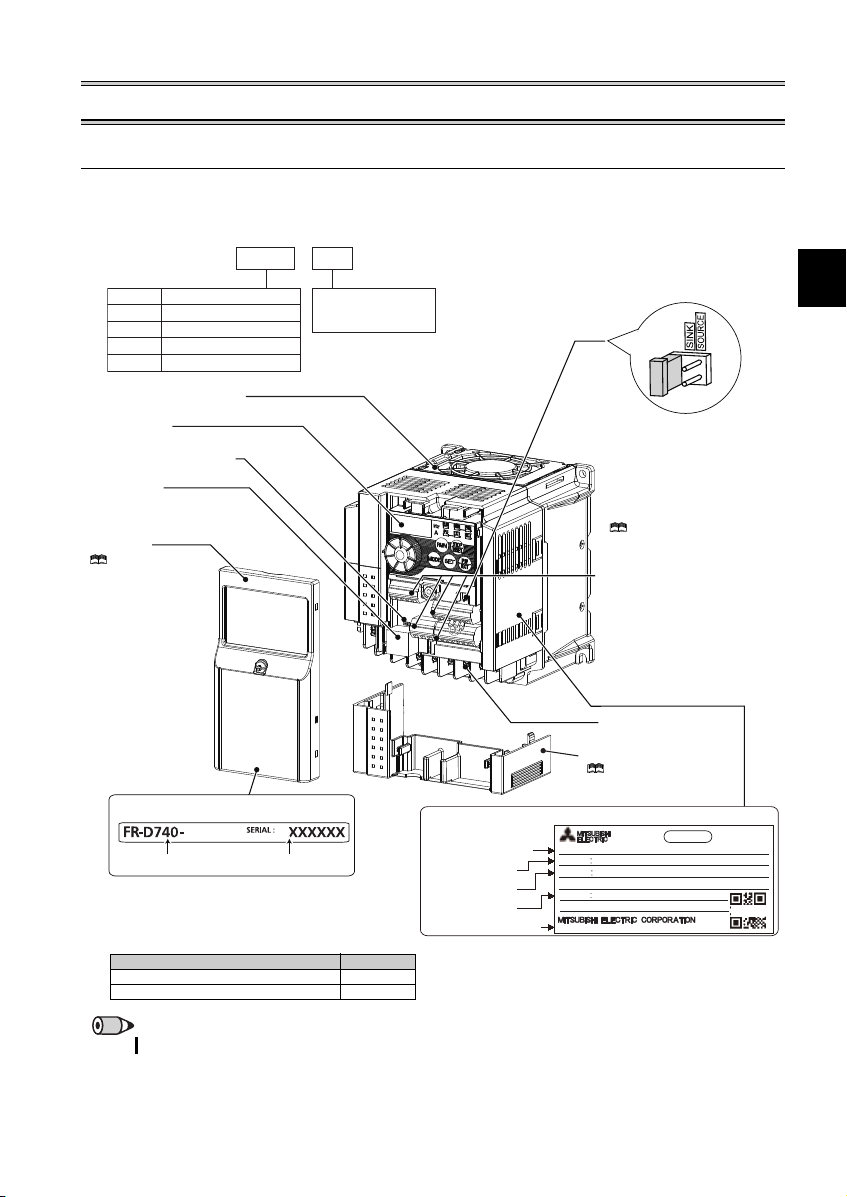
Control circuit terminal block
(Refer to page 9)
Control logic switchover jumper
connector
The jumper connector is in the sink
logic (SINK) when shipped from the
factory. Move the jumper connector
to change to the source logic
(SOURCE). Always fit the jumper
connector to the either position.
( Refer to the In struction Manual
(Applied))
Combed shaped wiring cover
Refer to the Instruction
Manual (Applied) for installation/
removal.
Main circuit termin al block
(Refer to page 9)
Front cover
Refer to the
Instruction Manual
(Applied) for installation/
removal.
PU connector
(Refer to page 8)
Voltage/current input switch
(Refer to page 8)
Operation panel
(Refer to page 2)
Cooling fan
The cooling fan is removable.
Accessory
· Fan cover fixing screws (M3 35mm)
These screws are necessary for compliance with
the EU Directive. (
Refer to page 46
)
Capacity Quantity
1.5K to 3.7K 1
5.5K to 15K 2
1.1 Product checking and parts identification
Unpack the inverter and check the capacity plate on the front cover and the rating plate on the inverter side face to ensure that
the product agrees with your order and the inverter is intact.
Inverter model
--
FR
D740 1.5
K
Symbol Voltage class
D720
D740
D720S
D710W
Capacity plate
Three-phase 200V class
Three-phase 400V class
Single-phase 200V class
Single-phase 100V class
1.5K
Inverter model
Represents the
inverter capacity [kW]
Serial number
Rating plate
Inverter model
Input rating
Output rating
Serial number
Country of origin
FR-D740-1.5K
MODEL
INPUT XXXXX
OUTPUT XXXXX
SERIAL
MADE IN JAPAN
PASS ED
INVERTER
SAMPLE
REMARKS
·
For how to find the SERIAL number, refer to page 50.
1
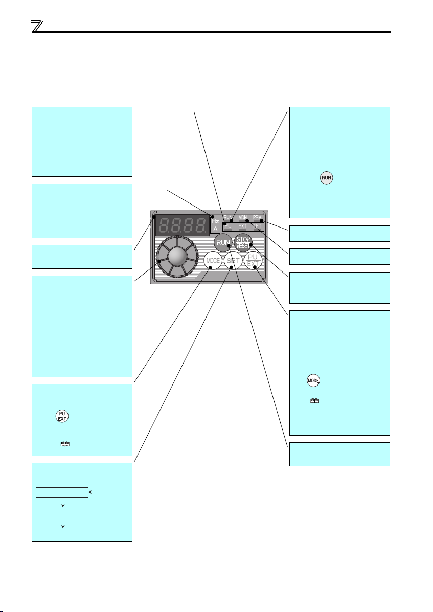
Operation panel
Operation mode indicator
PU: Lit to indicate PU operation mode.
EXT: Lit to indicate External operation mode.
(Lit at power-ON at initial setting.)
NET: Lit to indicate Network operation mode.
PU, EXT: Lit to indicate External/PU
combined operation mode 1, 2.
These turn OFF when command source is
not on operation panel.
Unit indicator
Hz: Lit to indicate frequency.
(Blinks when the set frequency
monitor is displayed.)
A: Lit to indicate current.
(Both "Hz" and "A" turn OFF when other
than the above is displayed.)
Monitor (4-digit LED)
Shows the frequency, parameter number,
etc.
Setting dial
(Setting dial: Mitsubishi Electric inverter
dial)
The setting dial is used to change the
frequency and parameter settings.
Press the setting dial to perform the
following operations:
To display a set frequency in the
monitor mode
To display the present setting during
calibration
To display a fault history number in the
fault history mode
Mode switchover
Used to switch among different setting
modes.
Pressing simultaneously changes
the operation mode.
Pressing for a while (2s) can lock
operation. (
Refer to the Instruction
Manual (Applied))
Determination of each setting
If pressed during operation, monitor
changes as below:
Operating status indicator
Lit or blink during inverter operation.
* Lit: When the forward rotation operation
is being performed.
Slow blinking (1.4s cycle):
When the reverse rotation operation
is being performed.
Fast blinking (0.2s cycle):
When was pressed or the start
command was given, but the
operation cannot be made.
When the frequency command is less
than the starting frequency.
When the MRS signal is input.
Parameter setting mode indicator
Lit to indicate param eter setting mode.
Monitor indicator
Lit to indicate monitoring mode.
STOP operation
Used to stop operation commands.
Used to reset a fault when the protective
function (fault) is activated.
Operation mode switchover
Used to switch between the PU and
External operation modes.
To use the External operation mode
(operation using a separately connected
frequency setting potentiometer and start
signal), press this key to light up the EXT
indicator.
(Press simultaneously (0.5s), or
change
Pr. 79
setting to change to combined
mode.)
( Refer to the Instruction
Manual (Applied))
PU: PU operation mode
EXT: External operation mode
Cancels PU stop also.
Start command
The rotation direction can be selected by
setting Pr. 40.
1.2 Operation panel
1.2.1 Names and functions of the operation panel
The operation panel cannot be removed from the inverter.
Running frequency
Output current
Output voltage
2
1
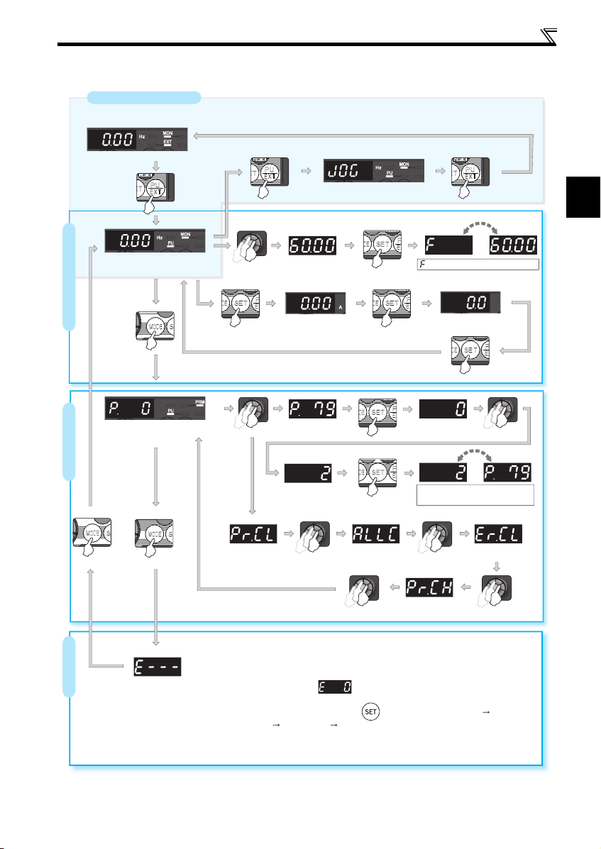
1.2.2 Basic operation (factory setting)
(Refer to page 37)
(Refer to page 4)
Operation mode switchover
At power-ON (External operation mode)
Operation panel
PU Jog operation mode
(Example)
PU operation mode
(output frequency monitor)
Parameter setting mode
Value change
Output current monitor
STOP
and frequency appear alternately.
Frequency setting has been
written and completed.
Output voltage monitor
Display the
present setting
(Example)
Parameter settingFault history Monitor/frequency setting
Value change
Parameter clear All parameter
clear
Parameter and a setting value
appear alternately.
Parameter write is completed.
Fault history clear
Initial value
change list
[Operation for displaying fault history]
The past eight faults can be displayed using the setting dial.
(The latest fault is ended by ".".)
When no fault history exists, is displayed.
While a fault is displayed:
The display shifts as follows by pressing : Output frequency at the fault
Output current Output voltage Energization time.
(After Energization time, it goes back to a fault display.)
Pressing the setting dial shows the fault history number.
3
Operation panel
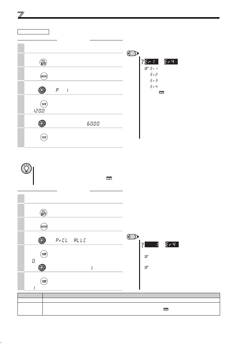
REMARKS
is displayed...Why?
appears .....Write disable error
appears
..... Write error during operation
appears .....Calibration error
appears .....Mode designation error
(For details, refer to the Instruction Manual (Appli ed).)
The number of digits displayed on the operation
panel is four. Only the upper four digits of values can
be displayed and set. If the values to be displayed
have five digits or more including decimal places, the
fifth or later numerals cannot be displayed nor set.
(Example) For Pr. 1
When 60Hz is set, 60.00 is displayed.
When 120Hz is set, 120.0 is displayed and second
decimal place is not displayed nor set.
to
REMARKS
are displayed alternately ...
Why?
The inverter is not in the PU operation mode.
(Refer to the step 2.)
PU connector is used (when a parameter unit
(FR-PU04/FR-PU07) is used ).
Stop the inverter. Parameter clear is unavailable
when the inverter is running, and will cause th e write
disable error.
and
1.2.3 Changing the parameter setting value
Operation example Change the Pr. 1 Maximum frequency setting.
Operation
Screen at power-ON
1.
The monitor display appears.
Operation mode change
2.
Press to choose the PU operation mo de. PU indicator is lit.
Parameter setting mode
3.
Press to choose the parameter set ting mode.
Selecting the parameter number
4.
Turn until " " (Pr. 1) appears.
Reading the setting value
Press to read the present set value.
5.
" "(120.0Hz (initial value)) appears.
Changing the setting value
6.
Turn to change the set value to " " (60.00Hz).
Setting the parameter
Press to set.
7.
The parameter number and the setting value blink alternately.
1.2.4 Parameter clear/all parameter clear
POINT
Set "1" in Pr.CL Parameter clear or ALLC All parameter clear to initialize parameters. (Parameters are not cleared
when "1" is set in Pr. 77 Parameter write selection.)
Refer to the extended parameter list of the Instruction Manual (Applied) for parameters cleared with this
operation.
Operation
Screen at power-ON
1.
The monitor display appears.
Operation mode change
2.
Press to choose the PU operation mode. PU indicator is lit.
Parameter setting mode
3.
Press to choose the parameter set ting mode.
Selecting Parameter Clear (All Parameter Clear)
4.
Turn until " " (" ") appears.
Selecting the setting value
Press to read the present set value.
5.
" "(initial value) appears.
Turn to change it to the set value " ".
Executing Parameter Clear
6.
4
Press to set.
" " and Pr. CL (ALLC) indications blink alternately.
Setting Description
0 Clear is not executed.
1
Sets parameters back to the initial values. (Parameter clear sets back all parameters except calibration parameters,
terminal function selection parameters to the initial valu es.) Refer to the parameter list of the Instruction Manual (Applied) for
availability of parameter clear and all parameter clear.
2
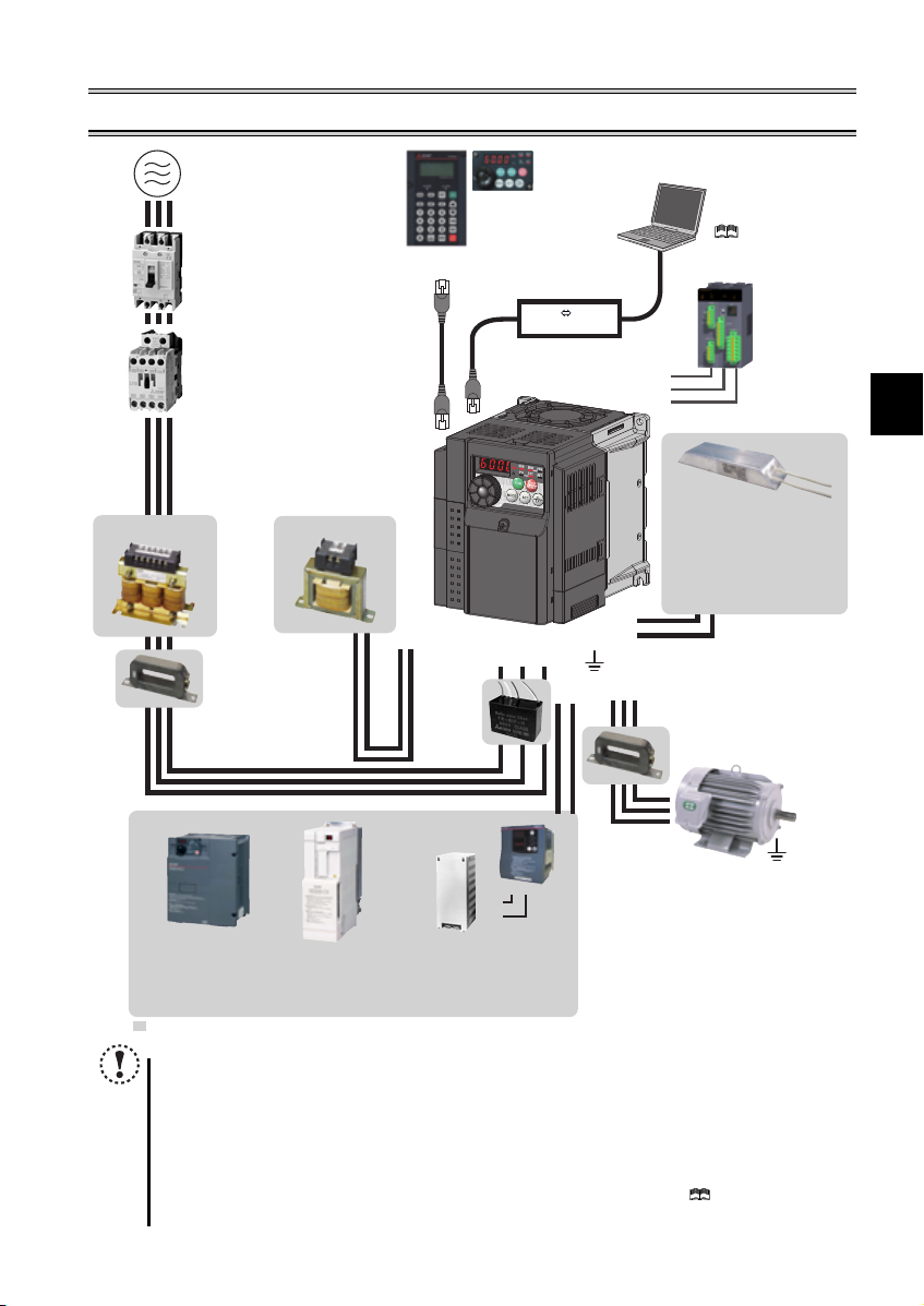
2 INSTALLATION AND WIRING
(Refer to page 43)
(Refer to page 6.)
(Refer to page 6.)
( Refer to the Instruction
Manual (Applied))
Brake resistor (FR-ABR,
MRS type, MYS type)
Braking capability can be
improved. (0.4K or higher)
Always install a thermal relay
when using a brake resistor
whose capacity is 11K or higher.
(Refer to page 18.)
AC power supply
Use within the permissible power supply
specifications of the inverter. To ensure
AC reactor (FR-HAL)
safety, use a molded case circuit breaker,
earth leakage circuit breaker or magnetic
contactor to switch power ON/OFF.
Molded case circuit breaker (MCCB)
or earth leakage circuit breaker
(ELB), fuse
The breaker must be selected carefully
since an in-rush current flows in the
inverter at power on.
Magnetic contactor (MC)
Install the magnetic contactor to ensure
safety. Do not use this magnetic contactor
to start and stop the inverter. Doing so will
cause the inverter life to be shortened.
Reactor (FR-HAL, FR-HEL option)
Reactors (option) must be used when
power harmonics measures are taken,
the power factor is to be improved or the
inverter is installed near a large power
supply system (500kVA or more). The
inverter may be damaged if you do not
use reactors. Select the reactor according
to the model. Remove the jumpers across
terminals P/+ and P1 to connect the DC reactor.
DC reactor (FR-HEL) *
Parameter unit
(FR-PU07)
Enclosure surface operation
panel (FR-PA07)
By connecting the connection cable
(FR-CB2) to the PU connector,
operation can be performed from
FR-PU07, FR-PA07.
RS-485 RS-232C
Converter
RS-232C - RS-485 converter is
required when connecting to PC
with RS-232C interface.
S1
S2
SC
Approved safety
relay module
Required for
compliance with
safety standard.
Noise filter (ferrite core) *
* Filterpack (FR-BFP2), which contains DC reactor and noise filter in one package, is also available.
(FR-BSF01, FR-BLF)
Install a noise filter (ferrite core)
to reduce the electromagnetic
noise generated from the
inverter. Effective in the range
from about 1MHz to 10MHz.
When more wires are passed
through, a more effective result
can be obtained. A wire should
be wound four turns or more.
High power factor
converter (FR-HC2)
Power supply harmonics
can be greatly suppressed.
: Install these options as required.
Power regeneration
common converter
(FR-CV)
Great braking capability
is obtained.
Inverter (FR-D700)
P1
P/+
Noise filter
(capacitor) *
(FR-BIF)
Reduces the
radio noise.
Resistor unit (FR-BR)
Discharging resistor (GZG, GRZG)
The regenerative braking capability
of the inverter can be exhibited fully.
Brake unit
(FR-BU2)
R/L1 S/L2T/L3
PR
P/+
P/+
PR
P/+
P/+
PR
Noise filter (ferrite core)
Earth (Ground)
N/-
Devices connected to the output
Do not install a power factor correction capacitor,
surge suppressor or noise filter (capacitor) on the output
side of the inverter. When installing a molded case
circuit breaker on the output side of the inverter,
contact each manufacturer for selection of the
molded case circuit breaker.
Earth (Ground)
To prevent an electric shock, always earth (ground)
the motor and inverter. For reduction of induction noise
from the power line of the inverter, it is recommended
to wire the earth (ground) cable by returning it to the
earth (ground) terminal of the inverter.
(FR-BSF01, FR-BLF)
Install a noise filter (ferrite core)
to reduce the electromagnetic
V
UW
noise generated from the inverter.
Effective in the range from about
1MHz to 10MHz. A wire should be
wound four turns at a maximum.
Motor
Earth (Ground)
NOTE
The life of the inverter is influenced by surrounding air temperature. The surrounding air temperature should be as
low as possible within the permissible range. This must be noted especially when the inverter is installed in an
enclosure. (
Wrong wiring might lead to damage of the inverter. The control signal lines must be kept fully away from the main
circuit to protect them from noise. (Refer to page 8.)
Do not install a power factor correction capacitor, surge suppressor or noise filter (capacitor) on the inverter output
side. This will cause the inverter to trip or the capacitor and surge suppressor to be damaged. If any of the above
devices are connected, immediately remove them.
Electromagnetic wave interference
The input/output (main circuit) of the inverter includes high frequency components, which may interfere with the communication
devices (such as AM radios) used near the inverter. In this case, install the FR-BIF optional noise filter (capacitor) (for use in the
input side only) or FR-BSF01 or FR-BLF noise filter (ferrite core) to minimize interference.
Instruction Manual (Applied)
Refer to the Instruction Manual of each option and peripheral devices for details of peripheral devices.
Refer to page 7
)
(
.)
Refer to Chapter 3 of the
5
Peripheral devices
MCCB INV
MCCB INV
IM
IM
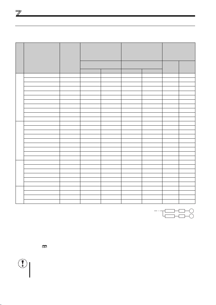
2.1 Peripheral devices
Check the inverter model of the inverter you purchased. Appropriate peripheral devices must be selected according to the capacity.
Refer to the following list and prepare appropriate peripheral devices.
Molded Case Circuit
Breaker (MCCB)
Applicable Inverter
Vol tag e
Model
Motor
Output
(kW)
or Earth Leakage Circuit
Breaker (ELB)
(NF or NV type)
Reactor or Filterpack
connection
without with without with
FR-D720-0.1K 0.1 5A 5A S-T10 S-T10 0.4K 0.4K
FR-D720-0.2K 0.2 5A 5A S-T10 S-T10 0.4K 0.4K
FR-D720-0.4K 0.4 5A 5A S-T10 S-T10 0.4K 0.4K
FR-D720-0.75K 0.75 10A 5A S-T10 S-T10 0.75K 0.75K
FR-D720-1.5K 1.5 15A 10A S-T10 S-T10 1.5K 1.5K
FR-D720-2.2K 2.2 20A 15A S-T10 S-T10 2.2K 2.2K
FR-D720-3.7K 3.7 30A 30A S-T21 S-T10 3.7K 3.7K
FR-D720-5.5K 5.5 50A 40A S-T35 S-T21 5.5K 5.5K
FR-D720-7.5K 7.5 60A 50A S-T35 S-T35 7.5K 7.5K
Three-Phase 200V class
FR-D720-11K 11 75A 75A S-T35 S-T35 11K 11K
FR-D720-15K 15 125A 100A S-T50 S-T50 15K 15K
FR-D740-0.4K 0.4 5A 5A S-T10 S-T10 H0.4K H0.4K
FR-D740-0.75K 0.75 5A 5A S-T10 S-T10 H0.75K H0.75K
FR-D740-1.5K 1.5 10A 10A S-T10 S-T10 H1.5K H1.5K
FR-D740-2.2K 2.2 15A 10A S-T10 S-T10 H2.2K H2.2K
FR-D740-3.7K 3.7 20A 15A S-T10 S-T10 H3.7K H3.7K
FR-D740-5.5K 5.5 30A 20A S-T21 S-T12 H5.5K H5.5K
FR-D740-7.5K 7.5 30A 30A S-T21 S-T21 H7.5K H7.5K
FR-D740-11K 11 50A 40A S-T21 S-T21 H11K H11K
Three-Phase 400V class
FR-D740-15K 15 60A 50A S-T35 S-T21 H15K H15K
FR-D720S-0.1K 0.1 5A 5A S-T10 S-T10 0.4K 0.4K
FR-D720S-0.2K 0.2 5A 5A S-T10 S-T10 0.4K 0.4K
FR-D720S-0.4K 0.4 10A 10A S-T10 S-T10 0.75K 0.75K
FR-D720S-0.75K 0.75 15A 10A S-T10 S-T1 0 1.5K 1.5K
FR-D720S-1.5K 1.5 20A 20A S-T10 S-T10 2.2K 2.2K
200V class
Single-Phase
FR-D720S-2.2K 2.2 40A 30A S-T21 S-T10 3.7K 3.7K
FR-D710W-0.1K 0.1 10A 5A S-T10 S-T10
FR-D710W-0.2K 0.2 10A 10A S-T10 S-T10 1.5K, —
FR-D710W-0.4K 0.4 15A 15A S-T10 S-T10 2.2K, —
100V class
FR-D710W-0.75K 0.75 30A 20A S-T10 S-T10 3.7K, —
Single-Phase
Select a MCCB according to the power supply capacity.
Install one MCCB per inverter.
For the use in the United States or Canada, refer to "Instructions for UL and cUL" in, and select an appropriate fuse
or molded case circuit breaker (MCCB).
Magnetic contactor is selected based on the AC-1 class. The electrical durability of magnetic contactor is 500,000 times. When the magnetic contactor is
used for emergency stop during motor driving, the electrical durability is 25 times.
If using an MC for emergency stop during motor driving, select an MC regarding the inverter input side current as JEM1038-AC-3 class rated current. When
using an MC on the inverter output side for commercial-power supply operation switching using a general-purpose motor, select an MC regarding the motor
rated current as JEM1038-AC-3 class rated current.
When connecting a single-phase 100V power input model to a power transformer (50kVA or more), install an AC reactor (FR-HAL) so that the performance
is more reliable. ( Refer to Chapter 3 of the Instruction Manual (Applied))
The power factor may be slightly lower.
Single-phase 100V power input model is not compatible with DC reactor.
NOTE
When the inverter capacity is larger than the motor capacity, select an MCCB and a magnetic contactor according to the inverter model,
and cable and reactor according to the motor output.
When the breaker on the inverter input side trips, check for the wiring fault (short circuit), damage to internal parts of the inverter, etc.
Identify the cause of the trip, then remove the cause and power ON the breaker.
Input Side Magnetic
Contactor (MC)
Reactor or Filterpack
connection
Reactor
FR-HAL FR-HEL
0.75K
,
—
6
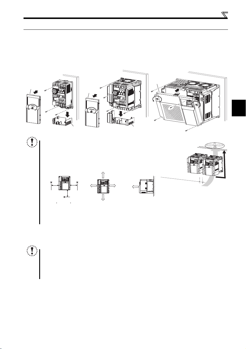
Installation of the inverters and precautions
2
Refer to the clearances below.
10cm or more
10cm or more
Measurement
position
Measurement
position
5cm
5cm
5cm
-10 C to +50 C
(non-freezing)
1cm or
more
∗1, ∗2
1cm or
more
∗1, ∗2
1cm or
more
∗1
2.2 Installation of the inverters and precautions
(1) Installation of the inverter
Enclosure surface mounting
Remove the front cover and wiring cover to mount the inverter to the surface. (Remove the covers in the directions of the
arrows.)
FR-D720-0.1K to 0.75K
FR-D720S-0.1K to 0.75K
FR-D710W-0.1K to 0.4K
Front cover
NOTE
When encasing multiple inverters, install them in parallel as a cooling
measure.
Install the inverter vertically.
For heat dissipation and maintenance, allow minimum clearance shown
in the figures below from the inverter to the other devices and to the
inner surface of the enclosure.
FR-D720-1.5K to 3.7K
FR-D740-0.4K to 3.7K
FR-D720S-1.5K, 2.2K
FR-D710W-0.75K
Front cover
Wiring cover Wiring cover
FR-D720-5.5K to 15K
FR-D740-5.5K to 15K
Front cover
Before installation, check that the environment meets the specifications on page 44.
(2) Environment
Allow 5cm or more clearance for 5.5K or higher.
When using the inverters at the surrounding air temperature of 40C or less, the inverters can be installed without any clearance between
them (0cm clearance).
Note
Install the inverter on a strong surface securely and vertically with bolts.
Leave enough clearances and take cooling measures.
Avoid places where the inverter is subjected to direct sunlight, high temperature and high humidity.
Install the inverter on a nonflammable wall surfa ce.
When designing or building an enclosure for the inverter, carefully consider influencing factors such as heat
generation of the contained devices and the operating environment.
7
Wiring
Earth
(Ground)
Motor
IM
Earth (Ground)
Three-phase
AC power
supply
MCCB MC
R/L1
P1 P/+
PR
N/-
S/L2
T/L3
U
V
W
Earth
(Ground)
*7 Brake resistor (FR-ABR, MRS type, MYS
type)
Install a thermal relay to prevent an
overheat and burnout of the brake resistor.
Always install a thermal relay when using
a brake resistor whose capacity is 11K or
higher.
(The brake resistor cannot be connected
to the 0.1K and 0.2K.)
*8 It is not necessary when
calibrating the indicator
from the operation panel.
*9 Operation and parameter setting can be
done from the parameter unit
(FR-PU07) and the enclosure surface
operation panel (FR-PA07).
(Use the option cable (FR-CB2 ).)
RS-485 communication can be utilized
from a personal computer and other
devices.
Forward
rotation start
Reverse
rotation start
Middle
speed
High
speed
Low
speed
Control input signals (No voltage input allowed)
24VDC power supply
(Common for external power supply transistor)
Contact input common
STR
STF
RH
RM
RL
SD
PC
Relay output
Running
Open collector output
Open collector output common
Sink/source common
RUN
SE
A
B
C
Frequency setting signals (Analog)
2 0 to 5VDC
10(+5V)
2
3
1
4 4 to 20mADC
Frequency
setting
potentiometer
1/2W1kΩ
Terminal 4
input
(Current
input)
(+)
(-)
5(Analog common)
*4 It is recommended to
use 2W1kΩ when the
frequency setting signal
is changed frequently.
*4
*2 When using terminals
PC-SD as a 24VDC
power supply, take care
not to short across
terminals PC and SD.
PU
connector
*1 DC reactor (FR-HEL)
When connecting a DC reactor, remove the
jumper across P1 and P/+.
Single-phase 100V power input model is
not compatible with DC reactor.
Control circuit terminal
Main circuit terminal
Sink logic
Jumper
*1
*7
*6
*2
*3
*5
The function of these
terminals can be
changed to the reset
signal, etc. with the input
terminal assignment
(Pr. 178 to Pr. 182)
.
Multi-speed selection
Terminal functions vary by
Pr. 190 RUN terminal function
selection
Terminal functions vary
by Pr. 192 A,B,C terminal
function selection
SINK
SOURCE
VI
*5
0 to 5VDC
(0 to 10VDC)
0 to 10VDC
*5 Terminal input specifications can be changed by analog
input specifications switchover (Pr. 267). Set the
voltage/current input switch in the "V" position to select
voltage input (0 to 5V/0 to10V) and "I" (initial value) to
select current input (4 to 20mA).
To use terminal 4 (initial setting is current input), set "4"
in any of Pr.178 to Pr.182 (input terminal function
selection) to assign the function, and turn ON AU signal.
Voltage/current
input switch
Main circuit
Control circuit
R
Relay output
(Fault output)
Brake unit
(Option)
FM
SD
Indicator
(Frequency meter, etc.)
+
-
Moving-coil type
1mA full-scale
Calibration resistor
*8
*9
*3 Terminal input specifications
can be changed by analog
input specifications
switchover (Pr. 73).
Terminal 10 and terminal 2
are used as PTC input
terminal (Pr. 561).
Safe stop input (Channel 1)
Safe stop input (Channel 2)
Safe stop input common
Safety stop signal
S1
S2
SC
SO
Shorting
wire
Single-phase
AC power
supply
MCCB MC
R/L1
S/L2
Single-phase power input
*6 Terminal P1 is not available for
single-phase 100V power input model.
*10 Common terminal of terminal SO is
terminal SC. (Connected to terminal SD
inside of the inverter.)
Safety monitor output *10
Terminal functions vary by Pr. 197 SO
terminal function selection
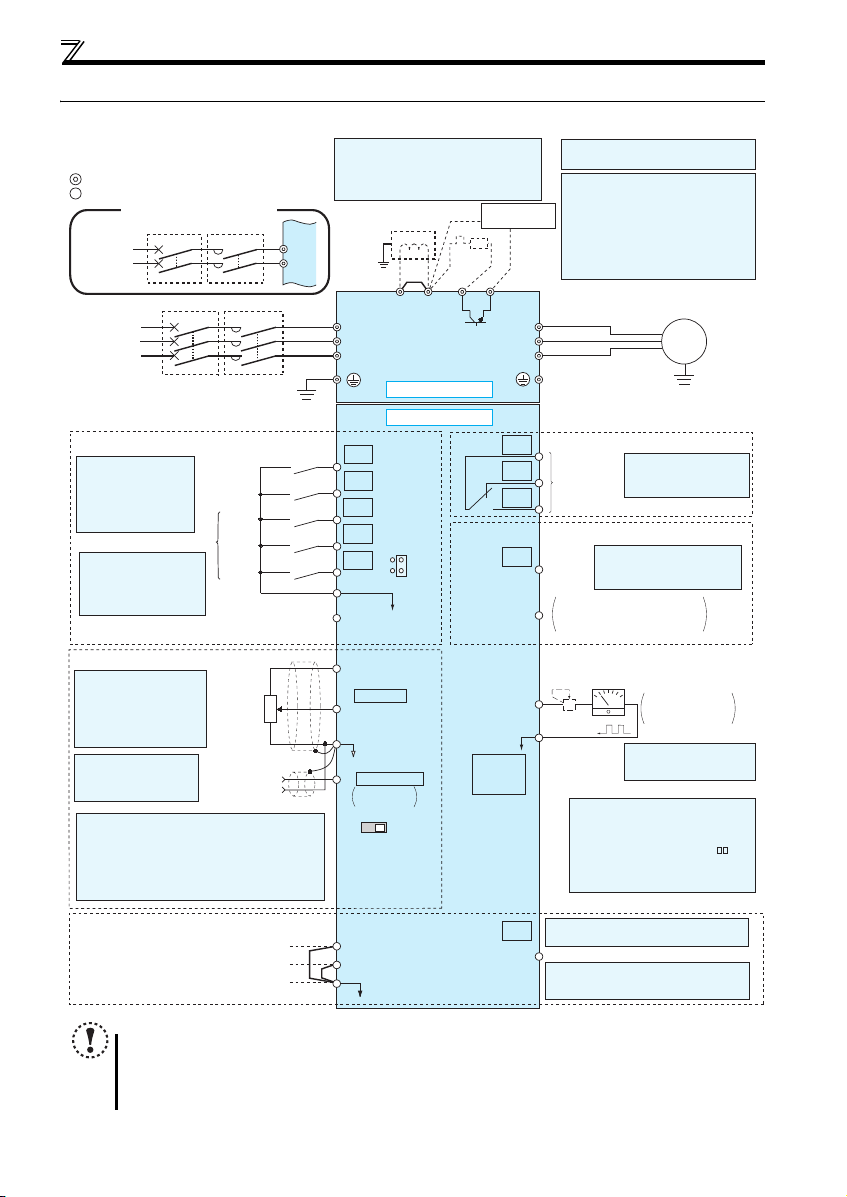
2.3 Wiring
2.3.1 Terminal connection diagram
NOTE
To prevent a malfunction caused by noise, separate the signal cables more than 10cm from the power cables. Also
separate the main circuit wire of the input side and the output side.
After wiring, wire offc uts must not be left in the inverter.
Wire offcuts can cause an alarm, failure or malfunction. Always keep the inverter clean. When drilling mounting holes
in an enclosure etc., take care not to allow chips and other foreign matter to enter the inverter.
The output of the single-phase power input model is three-phase 200V.
8
Wiring
2
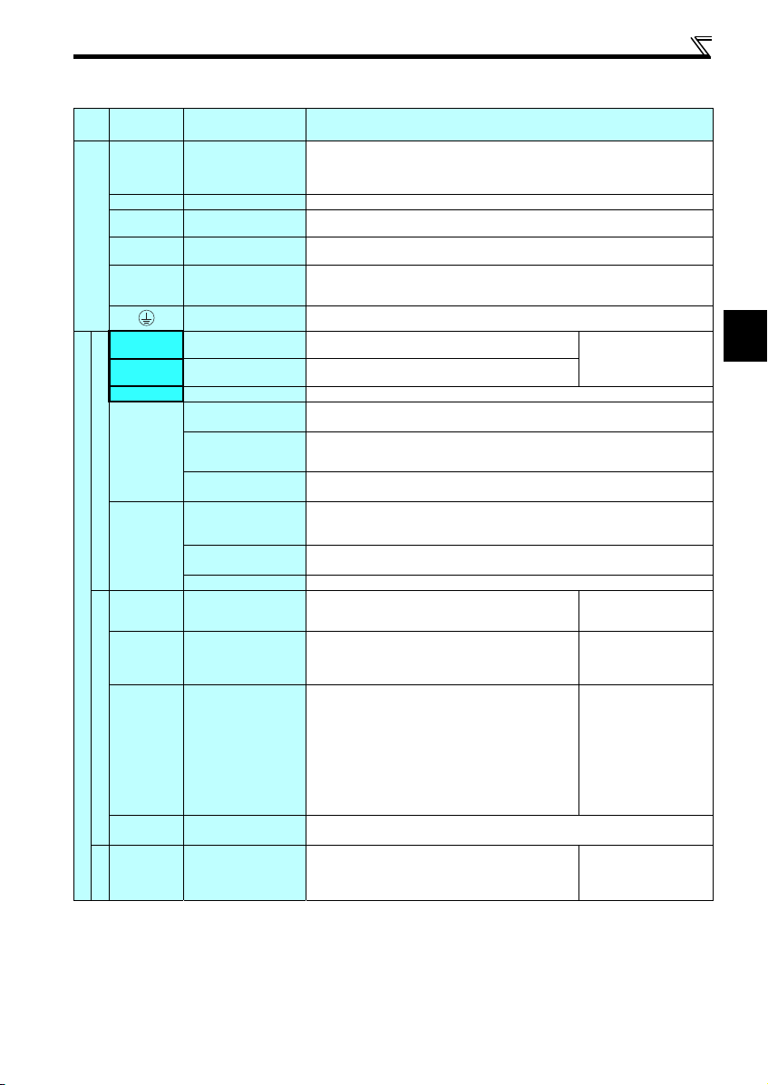
2.3.2 Terminal specifications
Terminal
Typ e
Symbol
R/L1, S/L2,
T/L3
U, V, W Inverter output
P/+, PR Brake resistor connection
P/+, N/- Brake unit connection
Main circuit terminal
P/+, P1 DC reactor connection
STF Forward rotation start
STR Reverse rotation start
RH, RM, RL Multi-speed selection
SD
Contact input
PC
10
2
Control circuit terminal/Input signal
4
Frequency setting
5
10
2
Thermistor
Terminal Name Terminal Specification
Connect to the commercial power supply.
AC power input
Earth (Ground)
Contact input common
(sink) (initial setting)
External transistor
common (source)
24VDC power supply
External transistor
common (sink)
(initial setting)
Contact input common
24VDC power supply
Frequency setting power
Frequency setting
Frequency setting
Frequency setting
PTC thermistor input
common
(source)
supply
(voltage)
(current)
common
Do not connect anything to these terminals when using the high power factor converter (FRHC2) or power regeneration common converter (FR-CV).
* When using single-phase power input, terminals are R/L1 and S/L2.
Connect a three-phase squirrel-cage motor.
Connect a brake resistor (FR-ABR, MRS type, MYS type) across terminals P/ + and PR.
(The brake resistor cannot be connect ed to the 0.1K and 0.2K.)
Connect the brake unit (FR-BU2), power regeneration common conve rter (FR-CV) or high
power factor converter (FR-HC2).
Remove the jumper across terminals P/+ and P1 and connect a DC reactor. (Single-phase
100V power input model is not compatible with the DC reactor.)
* Terminal P1 is not available for single-phase 100V power input model.
For earthing (grounding) the inverter chassis. Must be earthed (grounded).
Turn ON the STF signal to start forward rotation and turn it OFF
to stop.
Turn ON the STR signal to start reverse rotation and turn it
OFF to stop.
Multi-speed can be selected according to the combination of RH, RM and RL signals.
Common terminal for contact input terminal (sink logic) and terminal FM.
Connect this terminal to the power supply common terminal of a transistor output (open
collector output) device, such as a programmable controller, in the source logic to avoid
malfunction by undesirable current.
Common output terminal for 24VDC 0.1A power supply (PC terminal).
Isolated from terminals 5 and SE.
Connect this terminal to the power supply common terminal of a transistor output (open
collector output) device, such as a programmable controller, in the sink logic to avoid
malfunction by undesirable current.
Common terminal for contact input terminal (source logic).
Can be used as 24VDC 0.1A power supply.
Used as power supply when connecting potentiometer for
frequency setting (speed setting) from outside of the inverter.
Inputting 0 to 5VDC (or 0 to 10V) provides the maximum o utput
frequency at 5V (10V) and makes input and output
proportional. Use Pr. 73 to switch between input 0 to 5VDC
input (initial setting) and 0 to 10VDC.
Inputting 4 to 20mADC (or 0 to 5V, 0 to 10V) provides the
maximum output frequency at 20mA and makes input and
output proportional. This input signal is valid only when the AU
signal is ON (terminal 2 input is invalid). To use terminal 4
(initial setting is current input), set "4" in any of Pr.178 to Pr.182
(input terminal function selection) to assign the function, and turn
ON AU signal.
Use Pr. 267 to switch among input 4 to 20mA (initial setting), 0
to 5VDC and 0 to 10VDC. Set the voltage/current input switch
in the "V" position to select voltage input (0 to 5V/0 to 10V).
Frequency setting signal (terminal 2, 4) common terminal. Do not earth (ground) .
For connecting PTC thermistor output.
When PTC thermistor protection is valid (Pr. 561 "9999"),
terminal 2 is not available for frequency setting.
When the STF and STR
signals are turned ON
simultaneously, the stop
command is given.
5.0V0.2VDC
permissible load current
10mA
Input resistance10k1k
Permissible maximum voltage
20VDC
Current input:
Input resistance 2495
Maximum permissible current
30mA
Voltage input:
Input resistance10k 1k
Permissible maximum voltage
20VDC
Adaptive PTC thermistor
specification
Heat detection resistance :
500 to 30k (Set by Pr. 561)
9
Wiring
Terminal
Typ e
Symbol
A, B, C
Relay
RUN Inverter running
Open collector
SE
Control circuit terminal/Output signal
FM For meter
Pulse
— PU connecto r
Communication
S1
S2
SC
Safety stop function *
SO
* For more details, refer to the Safety stop function instruction manual (BCN-A211508-000). (Please contact your sales representative for the manual.)
NOTE
To change the input specification fo r terminal 4, set Pr. 267 and the voltage/current input switch correctly, then input
the analog signal relevant to the setting. Applying a voltage with voltage/current input switch in "I" position (current
input is selected) or a current with switch in "V" position (voltage input is selected) could cause component damage
to the inverter or analog circuit of output devices.
Connecting the power supply to the inverter output terminals (U, V, W) will damage the inverter. Do not perform such
wiring.
indicates that terminal functions can be selected using Pr. 178 to Pr. 182, Pr. 190, Pr. 192, Pr. 197 (I/O terminal
function selection).
The terminal names and functions shown here are the initial settings.
Terminal Name Terminal Specification
Relay output
(fault output)
Open collector output
common
Safety stop input
(Channel 1)
Safety stop input
(Channel 2)
Safety stop input terminal
common
Safety monitor output
(open collector output)
1 changeover contact output indicates that the inverter
protective function has activated and the output stopped.
Fault: discontinuity across B-C (continuity across A-C),
Normal: continuity across B-C (disco ntinuity across A-C)
Switched Low when the inverter output frequency is equal to or
higher than the starting frequency (initial value 0.5Hz).
Switched High during stop or DC injection brake operation.
(Low is when the open collector output transistor is ON
(conducts). High is when the transistor is OFF (does not
conduct).)
Common terminal of terminal RUN.
Used to output a selected monitored item (such as Output
frequency) among several monitored items.
(Not output during inverter reset.)
The output signal is proportional to the magnitude of the
corresponding monitored item.
With the PU connector, communication can be established through RS-485.
Conforming standard: EIA-485 (RS-485)
Transmission format: Multidrop link
Communication speed: 4800 to 38400bps
Overall length: 500m
Terminals S1 and S2 are for safety stop input signals used with
the safety relay module. Terminals S1 and S2 are used
simultaneously (dual channel). Inverter output is shut off by
shortening/opening across terminals S1 and SC and across S2
and SC. In the initial status, terminals S1 and S2 are shorted
with terminal SC by shortening wire.
Remove the shortening wire and connect the safety relay
module when using the safety stop function.
Common terminal for terminals S1, S2 and SO. Connected to terminal SD inside of the
inverter.
The signal indicates the status of safety stop input.
Low indicates safe state, and High indicates drive enabled or
fault detected.
(Low is when the open collector output transistor is ON
(conducts). High is when the transistor is OFF (does not
conduct).)
Contact capacity:230VAC
0.3A (power factor =0.4)
30VDC 0.3A
Permissible load 24VDC
(maximum 27VDC) 0.1A
(a voltage drop is 3.4V
maximum when the signal is
ON)
Permissible load current 1mA
1440 pulses/s at 60Hz
Input resistance 4.7k
Voltage when contacts are
open
21 to 26VDC
When contacts are shortcircuited
4 to 6mADC
Permissible load 24VDC
(maximum 27VDC) 0.1A
(a voltage drop is 3.4V
maximum when the signal is
ON)
10
Wiring
2
r
Motor
Power supply
N/-
P/+
PR
IM
R/L1 S/L2 T/L3
Jumper
MotorPower supply
N/-
P/+ PR
IM
Jumper
R/L1 S/L2
MotorPower supply
N/-
P/+ PR
IM
R/L1 S/L2
N/-
P/+
PR
R/L1 S/L2
MotorPower supply
IM
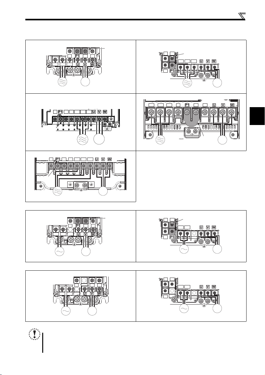
2.3.3 Terminal arrangement of the main circuit terminal, power supply and the motor wiring
Three-phase 200V/400V class
FR-D720-0.1K to 0.75K FR-D720-1.5K to 3.7K
N/-
P/+ PR
R/L1 S/L2 T/L3
Jumpe
FR-D740-0.4K to 3.7K
IM
MotorPower supply
FR-D720-5.5K, 7.5K
FR-D740-5.5K, 7.5K
N/-
Jumper
FR-D740-11K, 15K
N/-
Jumper
R/L1 S/L2 T/L3
P/+ PR
Power supply Motor
R/L1 S/L2 T/L3
P/+
PR
IM
FR-D720-11K, 15K
R/L1 S/L2 T/L3
N/-
P/+
PR
Jumper
IM
MotorPower supply
IM
Power supply
Single-phase 200V class
FR-D720S-0.1K to 0.75K FR-D720S-1.5K, 2.2K
Motor
P/+
Jumper
R/L1 S/L2
N/-
PR
Single-phase 100V class
FR-D710W-0.1K to 0.4K FR-D710W-0.75K
NOTE
Make sure the power cables are connected to the R/L1, S/L2, T/L3. (Phase need not be matched.) Never connect the
power cable to the U, V, W of the inverter. Doing so will damage the inverter.
Connect the motor to U, V, W. Turning ON the forward rotation switch (signal) at this t ime rotates the motor
counterclockwise when viewed from the load shaft.
IM
MotorPower supply
11
Wiring
3 × wire resistance [mΩ/m] × wiring distance [m] × current [A]
1000
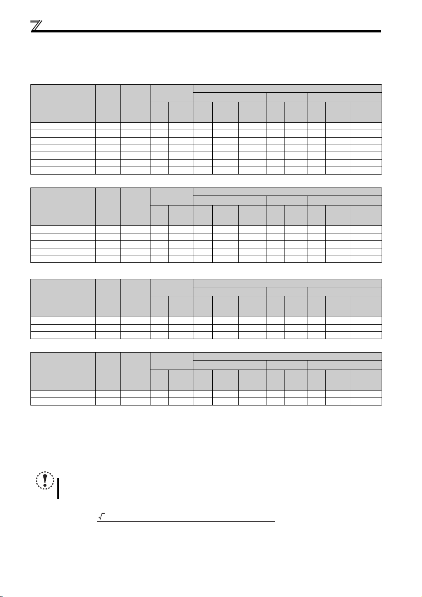
(1) Cable sizes etc., of the main control circuit terminals and earth (ground) terminals
Select the recommended cable size to ensure that a voltage drop will be 2% or less.
If the wiring distance is long between the inverter and motor, a main circuit cable voltage drop will cause the motor torque to
decrease especially at the output of a low frequency.
The following table indicates a selection example for the wiring length of 20m.
Three-phase 200V class (when input power supply is 220V)
Ter min al
Applicable Inverter
Model
FR-D720-0.1K to 0.75K M3.5 1.2 2-3.5 2-3.5 2 2 2 14 14 2.5 2.5 2.5
FR-D720-1.5K, 2.2K M4 1.5 2-4 2-4 2 2 2 14 14 2.5 2.5 2.5
FR-D720-3.7K M4 1.5 3.5-4 3.5-4 3.5 3.5 3.5 12 12 4 4 4
FR-D720-5.5K M5 2.5 5.5-5 5.5-5 5.5 5.5 5.5 10 10 6 6 6
FR-D720-7.5K M5 2.5 14-5 8-5 14 8 5.5 6 8 16 10 6
FR-D720-11K M5 2.5 14 -5 14-5 14 14 8 6 6 16 16 1 6
FR-D720-15K M6 (M5) 4.4 22-6 22-6 22 22 14 4 4 25 25 16
Screw
Size
Tightening
Tor que
N·m
Crimp
Terminal
R/L1
S/L2
T/L3
HIV Cables, etc. (mm2)
R/L1
U, V, W
S/L2
T/L3
U, V, W
Earthing
(grounding)
Three-phase 400V class (when input power supply is 440V)
Ter min al
Applicable Inverter
Model
FR-D740-0.4K to 3.7K M4 1.5 2-4 2-4 2 2 2 14 14 2.5 2.5 2.5
FR-D740-5.5K M4 1.5 3.5-4 2-4 3.5 2 3.5 12 14 4 2.5 4
FR-D740-7.5K M4 1.5 3.5-4 3.5-4 3.5 3.5 3.5 12 12 4 4 4
FR-D740-11K M4 1.5 5.5-4 5.5-4 5.5 5.5 5.5 10 10 6 6 10
FR-D740-15K M5 2.5 8-5 5.5-5 8 5.5 5.5 8 8 10 10 10
Screw
Size
Tightening
Tor que
N·m
Crimp
Terminal
R/L1
S/L2
T/L3
HIV Cables, etc. (mm2)
R/L1
U, V, W
S/L2
T/L3
U, V, W
Earthing
(grounding)
Single-phase 200V class (when input power supply is 220V)
Ter min al
Applicable Inverter
Model
FR-D720S-0.1K to 0.75K M3.5 1.2 2-3.5 2-3.5 2 2 2 14 14 2.5 2.5 2.5
FR-D720S-1.5K M4 1.5 2-4 2-4 2 2 2 14 14 2.5 2.5 2.5
FR-D720S-2.2K M4 1.5 3.5-4 2-4 3.5 2 3.5 12 14 4 2.5 4
Screw
Size
Tightening
Tor que
N·m
Crimp
Terminal
R/L1
S/L2
HIV Cables, etc. (mm2)
R/L1
U, V, W
S/L2
U, V, W
Earthing
(grounding)
Single-phase 100V class (when input power supply is 100V)
Ter min al
Applicable Inverter
Model
FR-D710W-0.1K to 0.4K M3.5 1.2 2-3.5 2- 3.5 2 2 2 14 14 2.5 2.5 2.5
FR-D710W-0.75K M4 1.5 3.5-4 2-4 3.5 2 2 12 14 4 2.5 2.5
The cable size is that of the cable (HIV cable (600V class 2 vinyl-insulated cable) etc.) with continuous maximum permissible temperature of 75°C. Assumes
that the surrounding air temperature is 50°C or less and the wiring distance is 20m or less.
The recommended cable size is that of the cable (THHW cable) with continuous maximum permissible temperature of 75°C. Assumes that the surrounding
air temperature is 40°C or less and the wiring distance is 20m or less. (For the use in the United States or Canada, refer to page 49.)
The recommended cable size is that of the cable (PVC cable) with continuous maximum permissible temperature of 70°C. Assumes that the surrounding air
temperature is 40°C or less and the wiring distance is 20m or less. (Selection example for use mainly in Europe.)
The terminal screw size indicates the terminal size for R/L1, S/L2, T/L3, U, V, W, PR, P/+, N/-, P1 and a screw for earthing (grounding).
Screw size for earthing (grounding) the FR-D720-15K is indicated in parentheses.
For single-phase power input, the terminal screw size indicates the size of terminal screw for R/L1, S/L2, U, V, W, PR, P/+, N/-, P1 and a screw for earthing
(grounding).
Screw
Size
Tightening
Tor que
N
Crimp
Terminal
R/L1
·
m
S/L2
HIV Cables, etc. (mm2)
R/L1
U, V, W
S/L2
U, V, W
Earthing
(grounding)
NOTE
Tighten the terminal screw to the specified torque. A screw that has been tightened too loosely can cause a short circuit or
malfunction. A screw that has been tightened too tightly can cause a short circuit or malfunction due to the unit breakage.
Use crimp terminals with insulation sleeve to wire the power supply and motor.
The line voltage drop can be calculated by the following formula:
Line voltage drop [V] =
Use a larger diameter cable when the wiring distance is long or when it is desired to decrease the voltage drop (torque
reduction) in the low speed range.
cable
cable
cable
cable
Cable Size
AWG
R/L1
S/L2
U, V, W
T/L3
Cable Size
AWG
R/L1
S/L2
U, V, W
T/L3
Cable Size
AWG
R/L1
U, V, W
S/L2
Cable Size
AWG
R/L1
U, V, W
S/L2
PVC Cables, etc. (mm2)
R/L1
S/L2
T/L3
PVC Cables, etc. (mm2)
R/L1
S/L2
T/L3
PVC Cables, etc. (mm2)
R/L1
S/L2
PVC Cables, etc. (mm2)
R/L1
S/L2
U, V, W
U, V, W
U, V, W
U, V, W
Earthing
(grounding)
cable
Earthing
(grounding)
cable
Earthing
(grounding)
cable
Earthing
(grounding)
cable
12
Wiring
2
Motor capacity 0.1kW 0.2kW 0.4kW or higher
Wiring length
20m 50m 100m
(2) Total wiring length
The overall wiring length for connection of a single motor or multiple motors should be within the value in the table below.
Cable
Typ e
Unshielded
cable
Shielded
cable
When driving a 400V class motor by the inverter, surge voltages attributable to the wiring constants may occur at the motor
terminals, deteriorating the insulation of the motor. Take the following measures 1) or 2) in this case.
1) Use a "400V class inverter-driven insulation-enhanced motor" and set frequency in Pr. 72 PWM frequency selection
2) Connect the surge voltage suppression filter (FR-ASF-H/FR-BMF-H) on the inverter output side.
Pr. 72 Setting
(carrier frequency)
1 (1kHz) or lower
2 (2kHz) or higher
1 (1kHz) or lower
2 (2kHz) or higher
Voltage Class 0.1K 0.2K 0.4K 0.75K 1.5K 2.2K
100V/200V 200m 200m 300m 500m 500m 500m 500m
400V - - 200m 200m 300m 500m 500m
100V/200V 30m 100m 200m 300m 500m 500m 500m
400V - - 30m 100m 200m 300m 500m
100V/200V 50m 50m 75m 100m 100m 100m 100m
400V - - 50m 50m 75m 100m 100m
100V/200V 10m 25m 50m 75m 100m 100m 100m
400V - - 10m 25m 50m 75m 100m
or Higher
according to wiring length
Wiring Length
50m or less 50m to 100m Exceeding 100m
Carrier frequency
14.5kHz or less 8kHz or less 2kHz or less
NOTE
Especially for long-distance wiring, the inverter may be affected by a charging current caused by the stray
capacitances of the wiring, leading to a malfunction of the overcurrent protective function, fast response current limit
function, or stall prevention function or a malfunction or fault of the equipment connected on the inverter output side.
If malfunction of fast-response current limit function occurs, disable this function. If malfunction of stall prevention
function occurs, increase the stall level. ( Refer to Pr. 22 Stall prevention operation level and Pr. 156 Stall prevention
operation selection in the chapter 4 of the Instruction Manual (applied))
When using the automatic restart after instantaneous power failure function with wiring length exceeding below,
select without frequency search (Pr. 162 = "1, 11"). (
Refer to Chapter 4 of the Instruction Manual (Applied))
3.7K
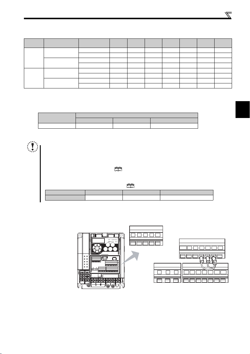
2.3.4 Wiring of control circuit
(1) Control circuit terminal layout
Recommend wire size:
2
0.3mm
to 0.75mm
2
10 2 5 4
FM
RUN SE S1 S2 SCSO
CBA
SD
STF
PCSDRHRMRL
STR
13
Wiring
10mm
Crumpled tip
Wires are not inserted
into the sleeve
Unstranded
wires
Damaged
WireWire
SleeveSleeve
0 to 0.5mm0 to 0.5mm
r
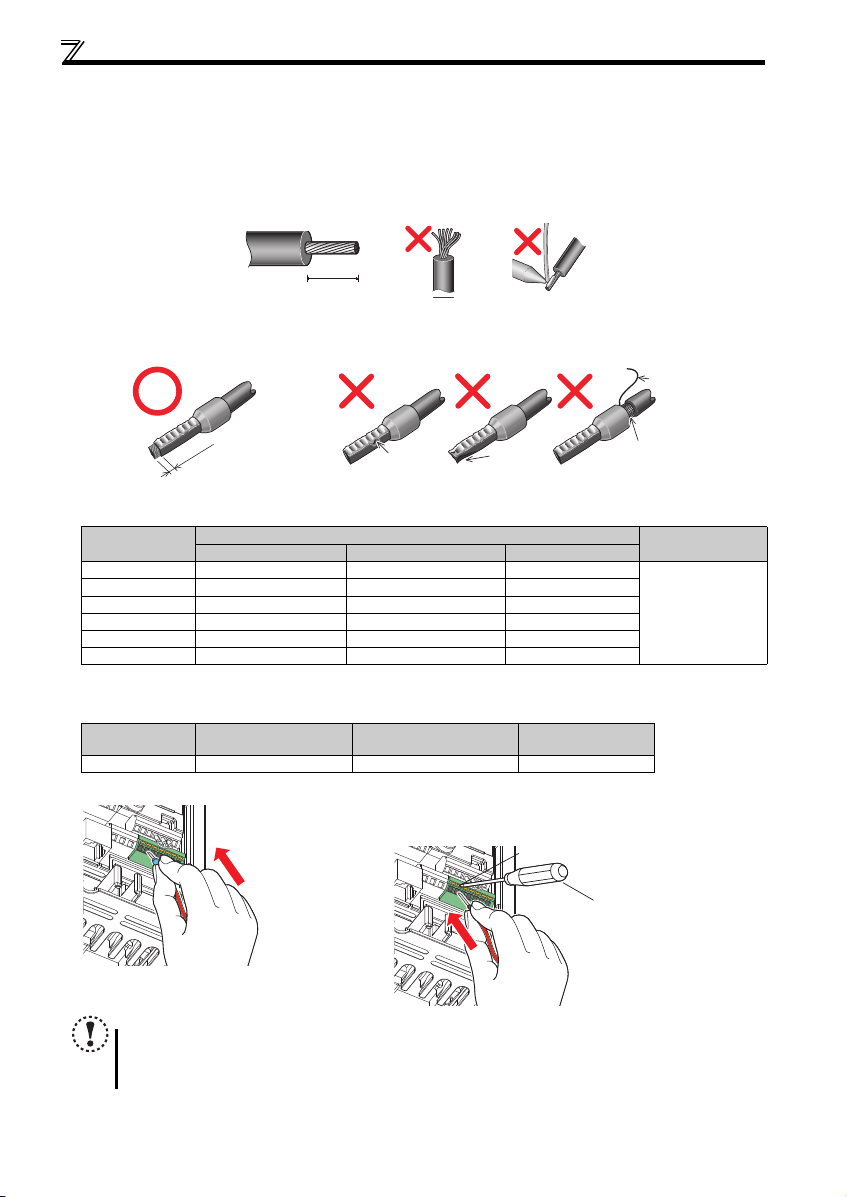
(2) Wiring method
Wiring
Use a blade terminal and a wire with a sheath stripped off for the control circuit wiring. For a single wire, strip off the sheath of
the wire and apply directly.
Insert the blade terminal or the single wire into a socket of the terminal.
1) Strip off the sheath about the length below. If the length of the sheath peeled is too long, a short circuit may occur
among neighboring wires. If the length is too short, wires might come off.
Wire the stripped wire after twisting it to prevent it from becoming loose. In addition, do not solder it.
2) Crimp the blade terminal.
Insert wires to a blade terminal, and check that the wires come out for about 0 to 0.5 mm from a sleeve.
Check the condition of the blade terminal after crimping. Do not use a blade terminal of which the crimping is
inappropriate, or the face is damaged.
Blade Terminals available on the market: (as of January 2017)
Phoenix Contact Co., Ltd.
Wire Size (mm2)
0.3 AI 0,34-10TQ — —
0.5 AI 0,5-10WH — AI 0,5-10WH-GB
0.75 AI 0,75-10GY A 0,75-10 AI 0,75-10GY-GB
1 AI 1-10RD A1-10 AI 1-10RD/1000GB
1.25, 1.5 AI 1,5-10BK A1,5-10 AI 1,5-10BK/1000GB
0.75 (for two wires) AI-TWIN 2 x 0,75-10GY — —
A ferrule terminal with an insulation sleeve compatible with MTW wire which has a thick wire insulation
Applicable for terminal ABC.
NICHIFU Co., Ltd.
Wire Size (mm2)
0.3 to 0.75 BT 0.75-11 VC 0.75 NH 69
3) Insert the wire into a socket.
Wire stripping length
Ferrule Terminal Model
With Insulation Sleeve Without Insulation Sleeve For UL Wire
Blade Terminal Product
Number
Insulation Cap Product
Number
Crimping Tool
Product Number
When using a single wire or a stranded wire without a
open/close button all the way down with a flathead screw driver, and insert the wire.
Open/close button
blade
Crimping Tool
Name
CRIMPFOX 6
terminal, push an
14
Flathead screwdrive
NOTE
When using a stranded wire without a blade terminal, twist enough to avoid short circuit with a nearby terminals or
wires.
Place the flathead screwdriver vertical to the open/close button. In case the blade tip slips, it may cause damage to
inverter or injury.
 Loading...