

Mitsubishi FR-D740-0.4K-G, FR-D720-1.5K-G, FR-D740-0.75K-G, FR-D740-1.5K-G, FR-D720-0.4K-G Instruction Manual
...
S-PM GEARED MOTOR DRIVE UNIT
FR-D700-G
INSTRUCTION MANUAL (Applied)
Simple and compact drive unit
FR-D720-0.2K to 3.7K-G
FR-D740-0.4K to 3.7K-G
According to the motor to be connected, perform PM
parameter initialization. Incorrect initial setting of parameters
may damage the motor. (Refer to page 73.)
The parameters for motor operation are initially set for an
S-PM geared motor.
PRECAUTIONS FOR USE
OF THE DRIVE UNIT
PARAMETERS
TROUBLESHOOTING
OUTLINE
WIRING
1
2
3
4
5
PRECAUTIONS FOR
MAINTENANCE AND INSPECTION
SPECIFICATIONS
6
7

Thank you for choosing this Mitsubishi Electric S-PM geared motor drive unit.
WARNING
CAUTION
CAUTION
WARNING
CAUTION
CAUTION
This Instruction Manual (Applied) provides instructions for advanced use of the FR-D700-G series drive units.
Incorrect handling might cause an unexpected fault. Before using the drive unit, always read this Instruction Manual
and the Instruction Manual (Basic) [IB-0600477ENG] packed with the product carefully to use the equipment to its
optimum performance.
2. Fire Prevention
This section is specifically about safety matters
Do not attempt to install, operate, maintain or inspect the drive
unit until you have read through the Instruction Manual and
appended documents carefully and can use the equipment
correctly. Do not use this product until you have a full
knowledge of the equipment, safety information and
instructions.
In this Instruction Manual, the safety instruction levels are
classified into "WARNING" and "CAUTION".
Incorrect handling may cause
hazardous conditions, resulting in death
or severe injury.
Incorrect handling may cause
hazardous conditions, resulting in
medium or slight injury, or may cause
only material damage.
The level may even lead to a serious
consequence according to conditions. Both instruction levels
must be followed because these are important to personal
safety.
1. Electric Shock Prevention
While the drive unit power is ON, do not remove the front
cover or the wiring cover. Do not run the drive unit with the
front cover or the wiring cover removed. Otherwise you may
access the exposed high voltage terminals or the charging
part of the circuitry and get an electric shock.
Even if power is OFF, do not remove the front cover except
for wiring or periodic inspection. You may accidentally
touch the charged drive unit circuits and get an electric
shock.
Before wiring or inspection, power must be switched OFF.
To confirm that, LED indication of the operation panel must
be checked. (It must be OFF.) Any person who is involved in
wiring or inspection shall wait for at least 10 minutes after
the power supply has been switched OFF and check that
there are no residual voltage using a tester or the like. The
capacitor is charged with high voltage for some time after
power OFF, and it is dangerous.
This drive unit must be earthed (grounded). Earthing
(grounding) must conform to the requirements of national
and local safety regulations and electrical code (NEC
section 250, IEC 61140 class 1 and other applicable
standards). A neutral-point earthed (grounded) power
supply for 400V class drive unit in compliance with EN
standard must be used.
Any person who is involved in wiring or inspection of this
equipment shall be fully competent to do the work.
The drive unit must be installed before wiring. Otherwise
you may get an electric shock or be injured.
Setting dial and key operations must be performed with dry
hands to prevent an electric shock. Otherwise you may get
an electric shock.
Do not subject the cables to scratches, excessive stress, heavy
loads or pinching. Otherwise you may get an electric shock.
Do not change the cooling fan while power is ON. It is
dangerous to change the cooling fan while power is ON.
Do not touch the printed circuit board or handle the cables
with wet hands. Otherwise you may get an electric shock.
When measuring the main circuit capacitor capacity, the DC
voltage is applied to the motor for 1s at powering OFF. Never
touch the motor terminal, etc. right after powering OFF to
prevent an electric shock.
A
PM motor is a synchronous motor with embedded
magnets. High-voltage is generated at motor terminals while
the motor is running even after the drive unit power is turned
OFF. Before wiring or inspection, the motor must be
confirmed to be stopped. For applications where the motor is
driven by the load, the low-voltage manual contactor, which
is installed at the drive unit's output side, must be opened
before wiring or inspection. Otherwise you may get an
electric shock.
The drive unit must be installed on a nonflammable wall
without holes (so that nobody touches the drive unit
heatsink on the rear side, etc.). Mounting it to or near
flammable material can cause a fire.
If the drive unit has become faulty, the drive unit power must
be switched OFF. A continuous flow of large current could
cause a fire.
When using a brake resistor, a sequence that will turn OFF
power when a fault signal is output must be configured.
Otherwise the brake resistor may overheat due to damage of
the brake transistor and possibly cause a fire.
Do not connect a resistor directly to the DC terminals P/+
and N/-. Doing so could cause a fire.
Be sure to perform daily and periodic inspections as
specified in the Instruction Manual. If a product is used
without any inspection, a burst, breakage, or a fire may
occur.
3.Injury Prevention
The voltage applied to each terminal must be the ones
specified in the Instruction Manual. Otherwise burst,
damage, etc. may occur.
The cables must be connected to the correct terminals.
Otherwise burst, damage, etc. may occur.
Polarity must be correct. Otherwise burst, damage, etc. may
occur.
While power is ON or for some time after power-OFF, do not
touch the drive unit since the drive unit will be extremely
hot. Doing so can cause burns.
A-1
4. Additional Instructions
CAUTION
Environment
Surrounding
air
temperature
-10°C to +50°C (non-freezing)
Ambient
humidity
90%RH or less (non-condensing)
Storage
temperature
-20°C to +65°C
Atmosphere
Indoors (free from corrosive gas, flammable gas,
oil mist, dust and dirt)
Altitude/
vibration
Maximum 1000 m.
5.9m/s
2
or less at 10 to 55Hz (directions of X, Y, Z
axes)
CAUTION
CAUTION
WARNING
CAUTION
Also the following points must be noted to prevent an accidental
failure, injury, electric shock, etc.
(1) Transportation and Mounting
The product must be transported in correct method that
Do not stack the boxes containing drive units higher than
The product must be installed to the position where
Do not install or operate the drive unit if it is damaged or has
When carrying the drive unit, do not hold it by the front
Do not stand or rest heavy objects on the product.
The drive unit mounting orientation must be correct.
Foreign conductive objects must be prevented from
As the drive unit is a precision instrument, do not drop or
The drive unit must be used under the following
If halogen-based materials (fluorine, chlorine, bromine,
(2) Wiring
Do not install a power factor correction capacitor or surge
The connection orientation of the output cables U, V, W to
PM motor terminals (U, V, W) hold high-voltage while the PM
Never connect a PM motor to the commercial power supply.
A-2
corresponds to the weight. Failure to do so may lead to
injuries.
the number recommended.
withstands the weight of the product according to the
information in the Instruction Manual.
parts missing.
cover or setting dial; it may fall off or fail.
entering the drive unit. That includes screws and metal
fragments or other flammable substance such as oil.
subject it to impact.
environment: Otherwise the drive unit may be damaged.
Temperature applicable for a short time, e.g. in transit.
iodine, etc.) infiltrate into a Mitsubishi Electric product, the
product will be damaged. Halogen-based materials are often
included in fumigant, which is used to sterilize or disinfest
wooden packages. When packaging, prevent residual
fumigant components from being infiltrated into Mitsubishi
Electric products, or use an alternative sterilization or
disinfection method (heat disinfection, etc.) for packaging.
Sterilization of disinfection of wooden package should also
be performed before packaging the product.
suppressor/capacitor type filter on the drive unit output
side. These devices on the drive unit output side may be
overheated or burn out.
the motor affects the rotation direction of the motor.
motor is running even after the power is turned OFF. Before
wiring, the PM motor must be confirmed to be stopped.
Otherwise you may get an electric shock.
Applying the commercial power supply to input terminals (U,
V, W) of a PM motor will burn the PM motor. The PM motor
must be connected with the output terminals (U, V, W) of the
drive unit.
(3) Trial run
Before starting operation, each parameter must be
confirmed and adjusted. A failure to do so may cause some
machines to make unexpected motions.
(4) Usage
A PM motor and the drive unit must be used in the specified
capacity combination.
Do not use multiple PM motors with one drive unit.
Any person must stay away from the equipment when the
retry function is set as it will restart suddenly after trip.
Since pressing the STOP/RESET key may not stop output
depending on the function setting status, separate circuit
and switch that make an emergency stop (power OFF,
mechanical brake operation for emergency stop, etc.) must
be provided.
OFF status of the start signal must be confirmed before
resetting the drive unit fault. Resetting drive unit alarm with
the start signal ON restarts the motor suddenly.
Do not use a PM motor in an application where a motor is
driven by its load and runs at a speed higher than the
maximum motor speed.
According to the motor to be connected, perform PM
parameter initialization. Incorrect initial setting of
parameters may damage the motor.
The parameters for motor operation are initially set for an SPM geared motor.
When other PM motors are used, set parameters according
to the motor.
Do not use the drive unit for a load other than the PM motor.
Connection of any other electrical equipment to the drive
unit output may damage the equipment.
Do not modify the equipment.
Do not perform parts removal which is not instructed in this
manual. Doing so may lead to fault or damage of the product.
The electronic thermal relay function does not guarantee
protection of the motor from overheating. It is recommended
to install an external thermal for overheat protection.
Do not use a magnetic contactor on the drive unit input for
frequent starting/stopping of the drive unit. Otherwise, the
life of the drive unit decreases.
The effect of electromagnetic interference must be reduced
by using an EMC filter or by other means. Otherwise nearby
electronic equipment may be affected.
Appropriate measures must be taken to suppress
harmonics. Otherwise power supply harmonics from the
drive unit may heat/damage the power factor correction
capacitor and generator.
When parameter clear or all parameter clear is performed,
the required parameters must be set again before starting
operations because all parameters return to the initial value.
The drive unit can be easily set for high-speed operation.
Before changing its setting, the performances of the motor
and machine must be fully examined.
Stop status cannot be hold by the drive unit's brake
function. In addition to the drive unit's brake function, a
holding device must be installed to ensure safety.
Before running a drive unit which had been stored for a long
period, inspection and test operation must be performed.
Static electricity in your body must be discharged before
you touch the product. Otherwise the product may be
damaged.
In the system with a PM motor, the drive unit power must be
turned ON before closing the contacts of the contactor at the
output side.
If you are installing the drive unit to drive a three-phase
device while you are contracted for lighting and power
service, consult your electric power supplier.
(5) Emergency stop
CAUTION
CAUTION
CAUTION
A safety backup such as an emergency brake must be
provided for devices or equipment in a system to prevent
hazardous conditions in case of failure of the drive unit or
an external device controlling the drive unit.
When the breaker on the drive unit input side trips, the
wiring must be checked for fault (short circuit), and internal
parts of the drive unit for a damage, etc. The cause of the trip
must be identified and removed before turning ON the power
of the breaker.
When any protective function is activated, appropriate
corrective action must be taken, and the drive unit must be
reset before resuming operation.
(6) Maintenance, inspection and parts replacement
Do not carry out a megger (insulation resistance) test on the
control circuit of the drive unit. It will cause a failure.
(7) Disposal
The drive unit must be treated as industrial waste.
General instruction
Many of the diagrams and drawings in this Instruction Manual
show the drive unit without a cover or partially open for
explanation. Never operate the drive unit in this manner. The
cover must be always reinstalled and the instruction in this
Instruction Manual must be followed when operating the drive
unit.
For more details on a PM motor, refer to the Instruction Manual of
the PM motor.
A-3

CONTENTS
1 OUTLINE 1
1.1 Product checking and parts identification......................................... 2
1.2 Drive unit and peripheral devices....................................................... 3
1.2.1 Peripheral devices .......................................................................................................................... 4
1.3 Removal and reinstallation of the cover ............................................ 6
1.3.1 Front cover...................................................................................................................................... 6
1.3.2 Wiring cover.................................................................................................................................... 7
1.4 Installation of the drive unit and enclosure design ........................... 8
1.4.1 Drive unit installation environment.................................................................................................. 8
1.4.2 Cooling system types for drive unit enclosure ..............................................................................10
1.5 Drive unit placement......................................................................... 11
1.5.1 Installation precautions ................................................................................................................. 12
2 WIRING 13
2.1 Wiring ................................................................................................ 14
2.1.1 Terminal connection diagram ....................................................................................................... 14
2.2 Main circuit terminal specifications ................................................ 15
2.2.1 Specification of main circuit terminal ............................................................................................ 15
2.2.2 Terminal arrangement of the main circuit terminal, power supply and the motor wiring............... 15
2.2.3 Cables and wiring length .............................................................................................................. 16
2.3 Control circuit specifications ........................................................... 18
2.3.1 Control circuit terminal .................................................................................................................. 18
2.3.2 Changing the control logic ............................................................................................................ 20
2.3.3 Wiring of control circuit ................................................................................................................. 22
2.3.4 Connection to the PU connector................................................................................................... 25
2.4 Connection of stand-alone option unit ............................................. 27
2.4.1 Connection of a dedicated external brake resistor
(MRS type, MYS type, FR-ABR) (0.4K or higher)......................................................................... 27
2.4.2 Connection of the brake unit (FR-BU2) ........................................................................................ 29
2.4.3 Connection of the high power factor converter (FR-HC2) ............................................................ 31
2.4.4 Connection of the power regeneration common converter (FR-CV) ............................................ 32
2.4.5 Connection of a DC reactor (FR-HEL).......................................................................................... 33
3 PRECAUTIONS FOR USE OF THE DRIVE UNIT 35
3.1 EMC and leakage currents................................................................ 36
I

3.1.1 Leakage currents and countermeasures ...................................................................................... 36
3.1.2 EMC measures ............................................................................................................................. 38
3.1.3 Power supply harmonics .............................................................................................................. 40
3.1.4 Harmonic suppression guideline in Japan....................................................................................41
3.2 Installation of power factor improving reactor ................................ 43
3.3 Power-OFF and magnetic contactor (MC)......................................... 44
3.4 Precautions for use of the drive unit ................................................ 45
3.5 Failsafe of the system which uses the drive unit ............................ 47
4 PARAMETERS 49
4.1 Operation panel ................................................................................. 50
4.1.1 Names and functions of the operation panel ................................................................................ 50
4.1.2 Basic operation (factory setting) ................................................................................................... 51
4.1.3 Easy operation mode setting (easy setting mode) ....................................................................... 52
4.1.4 Changing the parameter setting value.......................................................................................... 53
4.1.5 Displaying the set speed .............................................................................................................. 53
CONTENTS
4.2 Parameter list ....................................................................................54
4.2.1 parameter list ................................................................................................................................ 54
4.3 Test operation and gain adjustment of the PM sensorless vector
control............................................................................................... 73
4.3.1 Outline of the PM sensorless vector control ................................................................................ 73
4.3.2 Automatic parameter setting in accordance with the motor (Pr.998) .......................................... 73
4.3.3 Setting procedure of speed control.............................................................................................. 76
4.3.4 PM motor test operation (Pr. 800) ............................................................................................... 77
4.3.5 Adjusting the speed control gain (Pr. 820, Pr. 821) ..................................................................... 79
4.3.6 Gain adjustment of current controllers for the d axis and the q axis (Pr.824, Pr.825) ................. 81
4.4 Special adjustment function ............................................................ 82
4.4.1 Motor wiring resistance adjustment (Pr. 658) ............................................................................. 82
4.4.2 Adjustment for motor long-wiring (Pr. 643) ................................................................................. 82
4.5 Adjustment of the output torque (current) of the motor ................. 83
4.5.1 Stall prevention operation (Pr. 22, Pr. 48, Pr. 156, Pr. 157) ........................................................ 83
4.5.2 Start torque adjustment (Pr. 785) ................................................................................................ 86
4.6 Limiting the rotation speed.............................................................. 87
4.6.1 Maximum/minimum setting (Pr. 1, Pr. 2) ..................................................................................... 87
4.6.2 Avoiding mechanical resonance points (speed jumps) (Pr. 31 to Pr. 36) .................................... 88
4.7 Speed setting by external terminals................................................ 89
II

4.7.1 Operation by multi-speed operation (Pr. 4 to Pr. 6, Pr. 24 to Pr. 27, Pr. 232 to Pr. 239)............. 89
4.7.2 Jog operation (Pr. 15, Pr. 16) ...................................................................................................... 91
4.7.3 Remote setting function (Pr. 59) .................................................................................................. 93
4.8 Setting of acceleration/deceleration time and acceleration/
deceleration pattern ........................................................................ 97
4.8.1 Setting of the acceleration and deceleration time
(Pr. 7, Pr. 8, Pr. 20, Pr. 44, Pr. 45, Pr. 791, Pr. 792) .................................................................. 97
4.8.2 Minimum motor rotation speed (Pr. 13) ....................................................................................... 99
4.8.3 Acceleration/deceleration pattern (Pr. 29) ................................................................................. 100
4.9 Selection and protection of a motor ............................................. 101
4.9.1 Motor overheat protection (Electronic thermal O/L relay, PTC thermistor protection)
(Pr. 9, Pr. 561, Pr.600 to Pr.604)............................................................................................... 101
4.9.2 Applied motor (Pr.71) ................................................................................................................ 105
4.9.3 Offline auto tuning (Pr.9, Pr.71, Pr.80, Pr.81, Pr.83, Pr.84, Pr.90, Pr.92, Pr.93, Pr.96, Pr.672,
Pr.702, Pr.706, Pr.707, Pr.711, Pr.712, Pr.717, Pr.721, Pr.724 to Pr.726, Pr.859)................... 105
4.10 Motor brake and stop operation .................................................... 110
4.10.1 DC injection brake and pre-excitation (Pr. 10, Pr. 11, Pr. 795).................................................. 110
4.10.2 Brake opening request (BOF) signal (Pr. 281, Pr. 283) ............................................................ 112
4.10.3 Activating the electromagnetic brake (MBR signal, Pr. 736) ..................................................... 113
4.10.4 Selection of a regenerative brake (Pr. 30, Pr. 70) ..................................................................... 114
4.10.5 Stop selection (Pr. 250) ............................................................................................................. 116
4.11 Function assignment of external terminal and control ................ 117
4.11.1 Input terminal function selection (Pr. 178 to Pr. 182)................................................................. 117
4.11.2 Drive unit output shutoff (MRS) signal (Pr. 17) .......................................................................... 119
4.11.3 Condition selection of function validity by Second function selection (RT) signal ..................... 120
4.11.4 Start signal operation selection (STF, STR, STOP signal, Pr. 250) .......................................... 121
4.11.5 Output terminal function selection (Pr. 190, Pr. 192)................................................................. 123
4.11.6 Detection of rotation speed (SU, FU signal, Pr. 41 to Pr. 43, Pr. 870) ...................................... 127
4.11.7 Output current detection function
(Y12 signal, Y13 signal, Pr. 150 to Pr. 153, Pr. 166, Pr. 167) ................................................... 128
4.11.8 Remote output selection (REM signal, Pr. 495, Pr. 496) ........................................................... 130
4.11.9 Pulse train output of output power (Y79) signal (Pr. 799).......................................................... 131
4.12 Monitor display and monitor output signal ................................... 132
4.12.1 Speed display and speed setting (Pr. 37, Pr. 144, Pr. 505)....................................................... 132
4.12.2 Monitor display selection of DU/PU and terminal FM
(Pr. 52, Pr. 54, Pr. 170, Pr. 171, Pr. 268, Pr. 563, Pr. 564, Pr. 891).......................................... 134
4.12.3 Reference of the terminal FM (pulse train output) (Pr. 55, Pr. 56)............................................. 139
4.12.4 Terminal FM calibration (calibration parameter C0 (Pr. 900)) ................................................... 140
4.12.5 How to calibrate the terminal FM when using the operation panel ............................................ 141
4.13 Operation setting at fault occurrence........................................... 143
III

4.13.1 Retry function (Pr. 65, Pr. 67 to Pr. 69) ..................................................................................... 143
4.13.2 Input/output phase loss protection selection (Pr. 251, Pr. 872) ................................................. 145
4.13.3 Earth (ground) fault detection at start (Pr. 249) ......................................................................... 145
4.13.4 Overspeed protection (Pr. 374) ................................................................................................. 146
4.14 Speed setting by analog input (terminal 2, 4) ............................... 147
4.14.1 Analog input selection (Pr. 73, Pr. 267)..................................................................................... 147
4.14.2 Setting the speed by analog input (voltage input / current input) .............................................. 150
4.14.3 Response level of analog input and noise elimination (Pr. 74).................................................. 151
4.14.4 Bias and gain of speed setting voltage (current)
(Pr. 125, Pr. 126, Pr. 241, C2 (Pr. 902) to C7 (Pr. 905)) ........................................................... 152
4.14.5 Speed setting signal (current) bias/gain adjustment method..................................................... 154
4.15 Misoperation prevention and parameter setting restriction......... 157
4.15.1 Reset selection/disconnected PU detection/PU stop selection (Pr. 75) .................................... 157
4.15.2 Parameter write disable selection (Pr. 77)................................................................................. 160
4.15.3 Reverse rotation prevention selection (Pr. 78) .......................................................................... 161
4.15.4 Extended parameter display (Pr. 160)....................................................................................... 161
CONTENTS
4.15.5 Password function (Pr. 296, Pr. 297)......................................................................................... 162
4.16 Selection of operation mode and operation location .................... 164
4.16.1 Operation mode selection (Pr. 79)............................................................................................. 164
4.16.2 Setting the speed by the operation panel .................................................................................. 172
4.16.3 Setting the speed by the operation panel (Pr. 79 = 3) ............................................................... 174
4.16.4 Setting the speed by analog input (voltage input / current input) .............................................. 175
4.16.5 Operation mode at power-ON (Pr. 79, Pr. 340) ......................................................................... 176
4.16.6 Start command source and speed command source during communication
operation (Pr. 338, Pr. 339, Pr. 551) ......................................................................................... 177
4.17 Communication operation and setting .......................................... 181
4.17.1 Wiring and configuration of PU connector ................................................................................. 181
4.17.2 Initial settings and specifications of RS-485 communication
(Pr. 117 to Pr. 120, Pr. 123, Pr. 124, Pr. 549) ........................................................................... 184
4.17.3 Operation selection at communication error occurrence
(Pr. 121, Pr. 122, Pr. 502, Pr. 779) ............................................................................................ 185
4.17.4 Communication EEPROM write selection (Pr. 342) .................................................................. 190
4.17.5 Mitsubishi inverter protocol (computer link communication) ...................................................... 191
4.17.6 MODBUS RTU communication specifications
(Pr. 117, Pr. 118, Pr. 120, Pr. 122, Pr. 343, Pr. 502, Pr. 549, Pr. 779) ..................................... 203
4.18 Special operation and speed control ............................................. 216
4.18.1 PID control (Pr. 127 to Pr. 134, Pr. 553, Pr. 554, Pr. 575 to Pr. 577, C42 to C45).................... 216
4.18.2 Regeneration avoidance function (Pr. 665, Pr. 882, Pr. 883, Pr. 885, Pr. 886)......................... 228
4.19 Useful functions ............................................................................. 230
4.19.1 Cooling fan operation selection (Pr. 244) .................................................................................. 230
IV

4.19.2 Display of the lives of the drive unit parts (Pr. 255 to Pr. 259)................................................... 231
4.19.3 Maintenance timer alarm (Pr. 503, Pr. 504)............................................................................... 235
4.19.4 Current average value monitor signal (Pr. 555 to Pr. 557) ........................................................ 236
4.19.5 Free parameter (Pr. 888, Pr. 889) ............................................................................................. 238
4.19.6 Initiating a fault (Pr. 997)............................................................................................................ 238
4.19.7 Batch setting Mitsubishi Electric HMI (GOT) connection parameters (Pr. 999) ......................... 239
4.20 Setting the parameter unit and operation panel........................... 241
4.20.1 RUN key rotation direction selection (Pr. 40)............................................................................. 241
4.20.2 PU display language selection (Pr. 145).................................................................................... 241
4.20.3 Operation panel speed setting/key lock selection (Pr. 161)....................................................... 242
4.20.4 Magnitude of speed change setting (Pr. 295)............................................................................ 245
4.20.5 Buzzer control (Pr. 990)............................................................................................................. 246
4.20.6 PU contrast adjustment (Pr. 991) .............................................................................................. 246
4.21 Parameter clear/ All parameter clear............................................ 247
4.22 Initial value change list ................................................................. 248
4.23 Check and clear of the fault history.............................................. 249
5 TROUBLESHOOTING 251
5.1 Reset method of protective function ............................................. 252
5.2 List of fault or alarm indications .................................................... 253
5.3 Causes and corrective actions....................................................... 254
5.4 Correspondences between digital and actual characters ............ 264
5.5 Check first when you have a trouble.............................................. 265
5.5.1 Motor does not start.................................................................................................................... 265
5.5.2 Motor or machine is making abnormal acoustic noise ................................................................ 266
5.5.3 Drive unit generates abnormal noise .......................................................................................... 267
5.5.4 Motor generates heat abnormally ............................................................................................... 267
5.5.5 Motor rotates in the opposite direction........................................................................................ 267
5.5.6 Speed greatly differs from the setting ......................................................................................... 267
5.5.7 Acceleration/deceleration is not smooth ..................................................................................... 268
5.5.8 Speed varies during operation.................................................................................................... 268
5.5.9 Operation mode is not changed properly.................................................................................... 269
5.5.10 Operation panel display is not operating .................................................................................... 269
5.5.11 Motor current is too large............................................................................................................ 269
5.5.12 Speed does not accelerate ......................................................................................................... 270
5.5.13 Unable to write parameter setting............................................................................................... 270
6 PRECAUTIONS FOR MAINTENANCE AND INSPECTION 271
V

6.1 Inspection items.............................................................................. 272
6.1.1 Daily inspection .......................................................................................................................... 272
6.1.2 Periodic inspection ..................................................................................................................... 272
6.1.3 Daily and periodic inspection...................................................................................................... 273
6.1.4 Display of the life of the drive unit parts...................................................................................... 274
6.1.5 Checking the inverter and converter modules ............................................................................ 274
6.1.6 Cleaning ..................................................................................................................................... 275
6.1.7 Replacement of parts ................................................................................................................. 275
6.2 Measurement of main circuit voltages, currents and powers ....... 278
6.2.1 Measurement of powers ............................................................................................................. 280
6.2.2 Measurement of voltages and use of PT.................................................................................... 280
6.2.3 Measurement of currents............................................................................................................ 281
6.2.4 Use of CT and transducer .......................................................................................................... 281
6.2.5 Measurement of drive unit input power factor ............................................................................ 281
6.2.6 Measurement of converter output voltage (across terminals P/+ and N/-) ................................. 281
6.2.7 Measurement of drive unit output frequency .............................................................................. 281
6.2.8 Insulation resistance test using megger ..................................................................................... 282
6.2.9 Pressure test .............................................................................................................................. 282
CONTENTS
7 SPECIFICATIONS 283
7.1 Rating...............................................................................................284
7.2 Common specifications................................................................... 285
7.3 Outline dimension drawings............................................................286
7.4 Specifications of the S-PM geared motors .....................................288
7.4.1 Motor specifications.................................................................................................................... 288
7.4.2 Motor torque characteristic ......................................................................................................... 289
APPENDIX 291
Appendix 1 Options and products available on the market...................................... 292
Appendix 2 Precautions for use of the S-PM geared motor...................................... 294
Appendix 3 Specification change ................................................................................ 294
Appendix 4 Index........................................................................................................... 295
VI
<Abbreviations>
PU...................................................Operation panel and parameter unit (
Drive unit.........................................FR-D700-G series drive unit for Mitsubishi Electric S-PM geared motor
FR-D700-G.....................................FR-D700-G series drive unit for Mitsubishi Electric S-PM geared motor
Pr. ................................................... Parameter number (Number assigned to function)
PU operation...................................Operation using the PU (operation panel/FR-PU07)
External operation...........................Operation using the control circuit signals
Combined operation ....................... Operation using both the PU (operation panel/FR-PU07) and External operation
PM motor ........................................Permanent magnet motor: an IPM motor, an SPM motor, or the Mitsubishi Electric GV
series S-PM geared motor
<Trademarks>
Microsoft and Visual C++ are registered trademarks of Microsoft Corporation in the United States and/or other countries.
Company and product names herein are the trademarks and registered trademarks of their respective owners.
<Marks>
FR-PU07)
REMARKS :Additional helpful contents and relations with other functions are stated.
NOTE :Contents requiring caution or cases when set functions are not activated are stated.
POINT :Useful contents and points are stated.
Parameters referred to : Related parameters are stated.
<Notes on descriptions in this Instruction Manual>
Connection diagrams in this Instruction Manual appear with the control logic of the input terminals as sink logic, unless
otherwise specified. (For the control logic, refer to
Harmonic suppression guideline (when drive units are used in Japan)
All models of general-purpose drive units used by specific consumers are covered by "The Harmonic Suppression Guideline for Consumers
Who Receive High Voltage or Special High Voltage". (For further details, refer to page 41.)
page 20.)
VII

1 OUTLINE
This chapter explains the "OUTLINE" for use of this product.
Always read the instructions before using the equipment.
1.1 Product checking and parts identification ................................. 2
1.2 Drive unit and peripheral devices ............................................... 3
1.3 Removal and reinstallation of the cover..................................... 6
1.4 Installation of the drive unit and enclosure design ................... 8
1.5 Drive unit placement..................................................................... 11
1
2
3
4
5
6
7
1
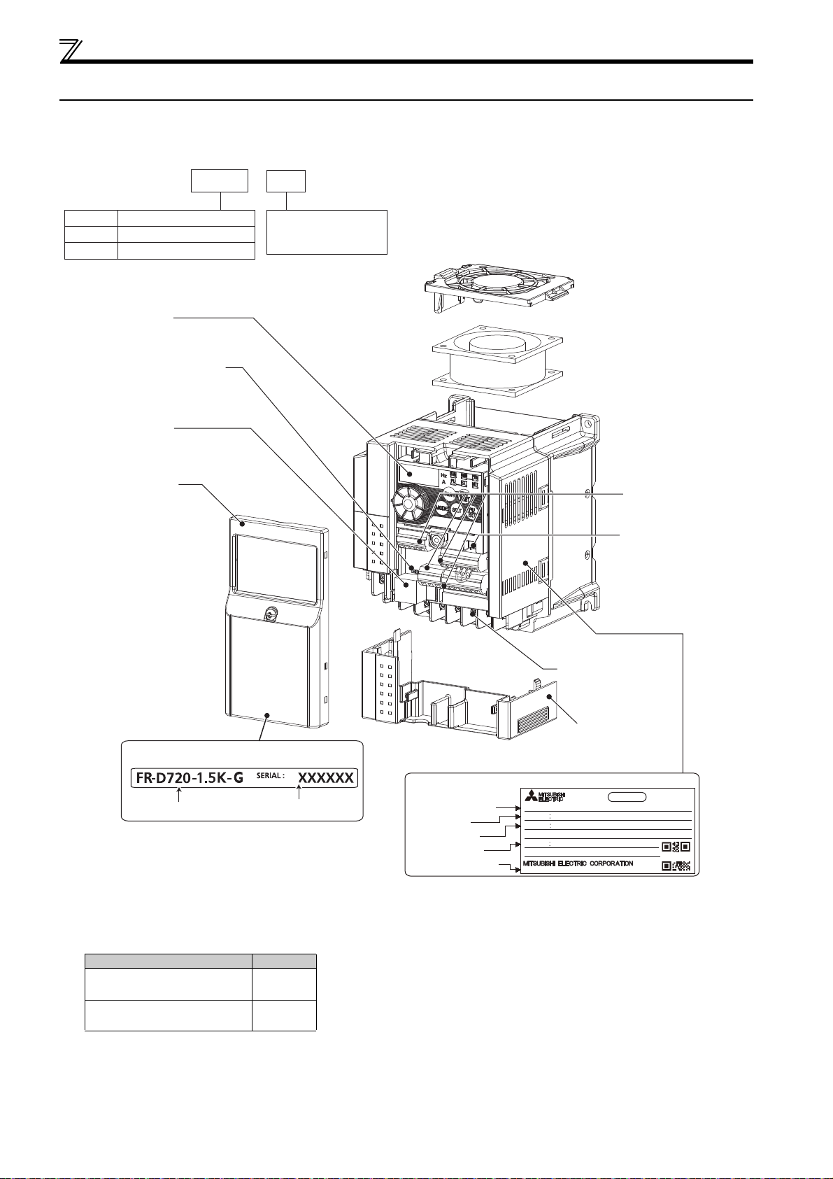
Product checking and parts identification
Capacity plate
Drive unit model
Serial number
Input rating
Output rating
Serial number
Rating plate
Drive unit model
ᴾ
MODEL FR-D720-1.5K-G
INPUT XXXXX
OUTPUT XXXXX
SERIAL
MADE IN JAPAN
PAS SE D
DRIVE UNIT
Country of origin
SAMPLE
FR
--
Symbol Voltage class
D720 1.5
Represents the drive
unit capacity [kW]
K
D720
D740
Three-phase 200V class
Three-phase 400V class
-
G
Control circuit terminal
block
(Refer to page 18.)
Control logic switchover
jumper connector
(Refer to page 20.)
Combed shaped
wiring cover
(Refer to page 7.)
Main circuit
terminal block
(Refer to page 15.)
Front cover
(Refer to page 6.)
PU connector
(Refer to page 25.)
Voltage/current input switch
(Refer to page 18.)
Operation panel
(Refer to page 50.)
Cooling fan
(Refer to page 275.)
1.1 Product checking and parts identification
Unpack the drive unit and check the capacity plate on the front cover and the rating plate on the drive unit side face to ensure
that the product agrees with your order and the drive unit is intact.
Drive unit model
Accessory
·Fan cover fixing screws (M3 35mm)
These screws are necessary for compliance with the EU Directive.
Capacity Quantity
D720-0.2K to 0.75K-G
D740-0.4K-G, 0.75K-G
D720-1.5K to 3.7K-G
D740-1.5K to 3.7K-G
none
1
2
1
OUTLINE
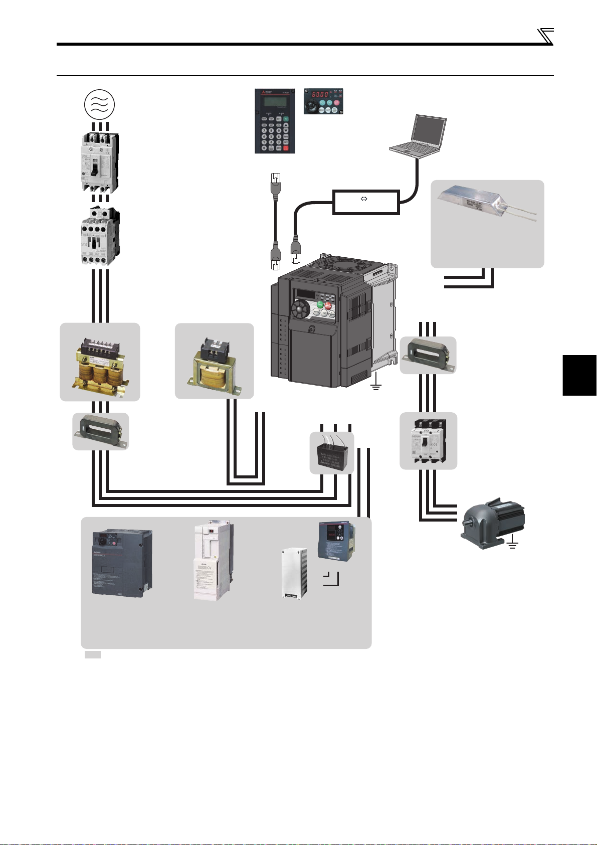
1.2 Drive unit and peripheral devices
(Refer to page 284.)
(Refer to page 4.)
(Refer to page 44.)
(Refer to page 181.)
Brake resistor (FR-ABR,
MRS type, MYS type)
Braking capability can be improved.
(0.4K or higher)
(Refer to page 27.)
(Refer to page 25.)
AC power supply
Use within the permissible power supply
specifications of the drive unit. To ensure
Reactor (FR-HAL, FR-HEL option)
Reactors (option) must be used when
power harmonics measures are taken,
the power factor is to be improved or the
drive unit is installed near a large power
supply system (500kVA or more). The
drive unit may be damaged if you do not
use reactors. Select the reactor according
to the model. Remove the jumpers across
AC reactor (FR-HAL)
terminals P/+ and P1 to connect the DC reactor.
safety, use a molded case circuit breaker,
earth leakage circuit breaker or magnetic
contactor to switch power ON/OFF.
Molded case circuit breaker (MCCB)
or earth leakage circuit breaker
(ELB), fuse
The breaker must be selected carefully
since an in-rush current flows in the
drive unit at power on.
Magnetic contactor (MC)
Install the magnetic contactor to ensure
safety. Do not use this magnetic contactor
to start and stop the drive unit. Doing so will
cause the drive unit life to be shorten.
DC reactor (FR-HEL) ∗
Parameter unit
(FR-PU07)
Noise filter (ferrite core) ∗
(FR-BSF01, FR-BLF)
Install a noise filter (ferrite core)
to reduce the electromagnetic
noise generated from the drive
unit. Effective in the range from
about 1MHz to 10MHz. When
more wires are passed through,
a more effective result can be
obtained. A wire should be
wound four turns or more.
P1
P/+
Noise filter
(capacitor) ∗
(FR-BIF)
Reduces the
radio noise.
Enclosure surface operation
panel (FR-PA07)
By connecting the connection
cable (FR-CB2) to the PU
connector, operation can be
performed from FR-PU07,
FR-PA07.
Drive unit
(FR-D700-G)
R/L1 S/L2T/L3
Drive unit and peripheral devices
RS-232C - RS-485 converter is
required when connecting to PC
with RS-232C interface.
RS-485 RS-232C
Converter
P/+
PR
Noise filter (ferrite core)
V
UW
Earth
(Ground)
N/-
P/+
(FR-BSF01, FR-BLF)
Install a noise filter (ferrite
core) to reduce the
electromagnetic
noise generated from the
drive unit. Effective in the
range from about 1MHz to
10MHz. A wire should be
wound four turns at a
maximum.
Contactor
Example: No-fuse switch
(DSN type)
Install a contactor in an
application where the PM
motor is driven by the load
even at power-OFF of the
drive unit. Do not open or
close the contactor while
the drive unit is running
(outputting).
∗ Filterpack (FR-BFP2), which contains DC reactor and noise filter in one package, is also available.
Brake unit
(FR-BU2)
PR
P/+
P/+
PR
High power factor
converter (FR-HC2)
Power supply harmonics
can be greatly suppressed.
: Install this as required.
Power regeneration
common converter
(FR-CV)
Great braking capability
is obtained.
Resistor unit (FR-BR)
Discharging resistor (GZG, GRZG)
The regenerative braking capability
of the drive unit can be exhibited fully.
Devices connected to the output
Do not install a power factor correction capacitor, surge
suppressor or noise filter (capacitor) on the output side
of the drive unit. When installing a molded case circuit
breaker on the output side of the drive unit, contact
each manufacturer for selection of the molded case
circuit breaker.
Earth (Ground)
To prevent an electric shock, always earth (ground) the
motor and drive unit. For reduction of induction noise
from the power line of the drive unit, it is recommended
to wire the earth (ground) cable by returning it to the
earth (ground) terminal of the drive unit.
Motor
Earth
(Ground)
3
Drive unit and peripheral devices
NOTE
The life of the drive unit is influenced by surrounding air temperature. Pay attention to the surrounding air
temperature. This must be noted especially when the drive unit is installed in an enclosure. (
Wrong wiring might lead to damage of the drive unit. The control signal lines must be kept fully away from the main
circuit to protect them from noise. (Refer to page 14.)
Do not install a power factor correction capacitor, surge suppressor or noise filter (capacitor) on the drive unit output
side. This will cause the drive unit to trip or the capacitor and surge suppressor to be damaged. If any of the above
devices are connected, immediately remove them.
Electromagnetic wave interference
The input/output (main circuit) of the drive unit includes high frequency components, which may interfere with the
communication devices (such as AM radios) used near the drive unit. In this case, install the FR-BIF optional noise
filter (capacitor) (for use in the input side only) or FR-BSF01 or FR-BLF noise filter (ferrite core) to minimize
interference. (
Refer to the Instruction Manual of each option and peripheral devices for details of peripheral devices.
A PM motor cannot be driven by the commercial power supply.
A PM motor is a magnet motor. High-voltage is generated at motor terminals while the motor is running even after the
drive unit power is turned OFF. Before closing the contactor on the output side, make sure that the drive unit power is
ON and the motor is stopped.
Refer to page 38
.)
Refer to page 8
.)
1.2.1 Peripheral devices
Check the drive unit model of the drive unit you purchased. Appropriate peripheral devices must be selected according to the
capacity.
Refer to the following list and prepare appropriate peripheral devices.
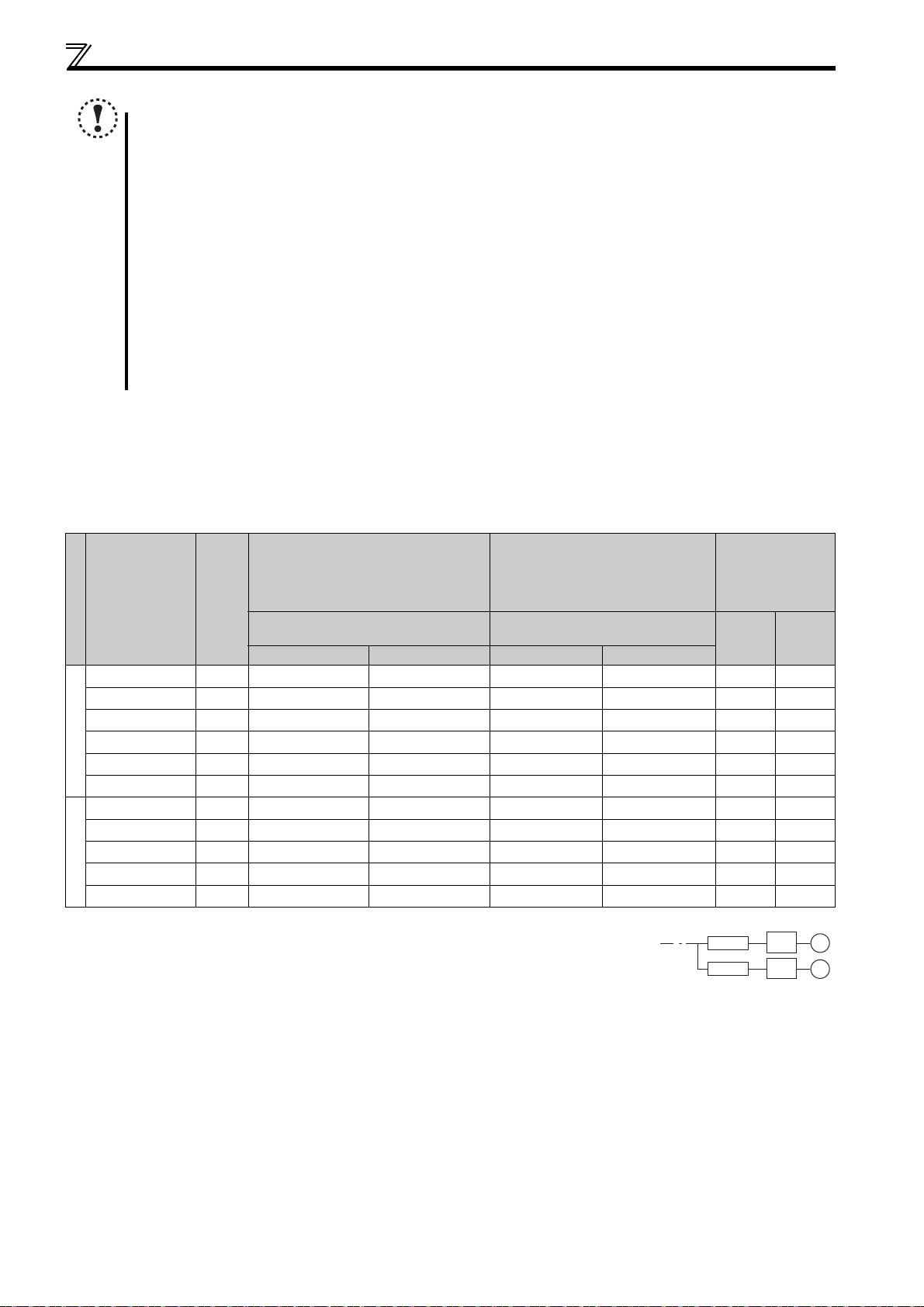
(1) S-PM geared motor
Molded Case Circuit Breaker
(MCCB) or
Input Side Magnetic Contactor Reactor
Power factor improving (AC or DC)
reactor connection
FR-HAL FR-HEL
Applicable Drive
Unit Model
Vol tage
Motor
Output
(kW)
Earth Leakage Circuit Breaker
(ELB)
(NF or NV type)
Power factor improving (AC or DC)
reactor connection
Without With Without With
FR-D720-0.2K-G 0.1 5A 5A S-T10 S-T10 0.4K 0.4K
FR-D720-0.4K-G 0.2 5A 5A S-T10 S-T10 0.4K 0.4K
FR-D720-0.75K-G 0.4 10A 5A S-T10 S-T10 0.4K 0.4K
FR-D720-1.5K-G 0.75 15A 10A S-T10 S-T10 0.75K 0.75K
200V class
FR-D720-2.2K-G 1.5 20A 15A S-T10 S-T10 1.5K 1.5K
FR-D720-3.7K-G 2.2 30A 30A S-T21 S-T10 2.2K 2.2K
FR-D740-0.4K-G 0.2 5A 5A S-T10 S-T10 H0.4K H0.4K
FR-D740-0.75K-G 0.4 5A 5A S-T10 S-T10 H0.4K H0.4K
FR-D740-1.5K-G 0.75 10A 10A S-T10 S-T10 H0.75K H0.75K
FR-D740-2.2K-G 1.5 15A 10A S-T10 S-T10 H1.5K H1.5K
400V class
FR-D740-3.7K-G 2.2 20A 15A S-T10 S-T10 H2.2K H2.2K
Select an MCCB according to the power supply capacity.
Install one MCCB per drive unit.
For the use in the United States or Canada, refer to "Instructions for UL and cUL" in the Instruction Manual (Basic),
and select an appropriate fuse or molded case circuit breaker (MCCB).
Magnetic contactor is selected based on the AC-1 class. The electrical durability of magnetic contactor is 500,000 times. When the magnetic contactor is
used for emergency stop during motor driving, the electrical durability is 25 times.
If using an MC for emergency stop during motor driving, select an MC regarding the drive unit input side current as JEM1038-AC-3 class rated current.
The power factor may be slightly lower.
MCCB
MCCB
Drive
unit
Drive
unit
M
M
4
1
OUTLINE
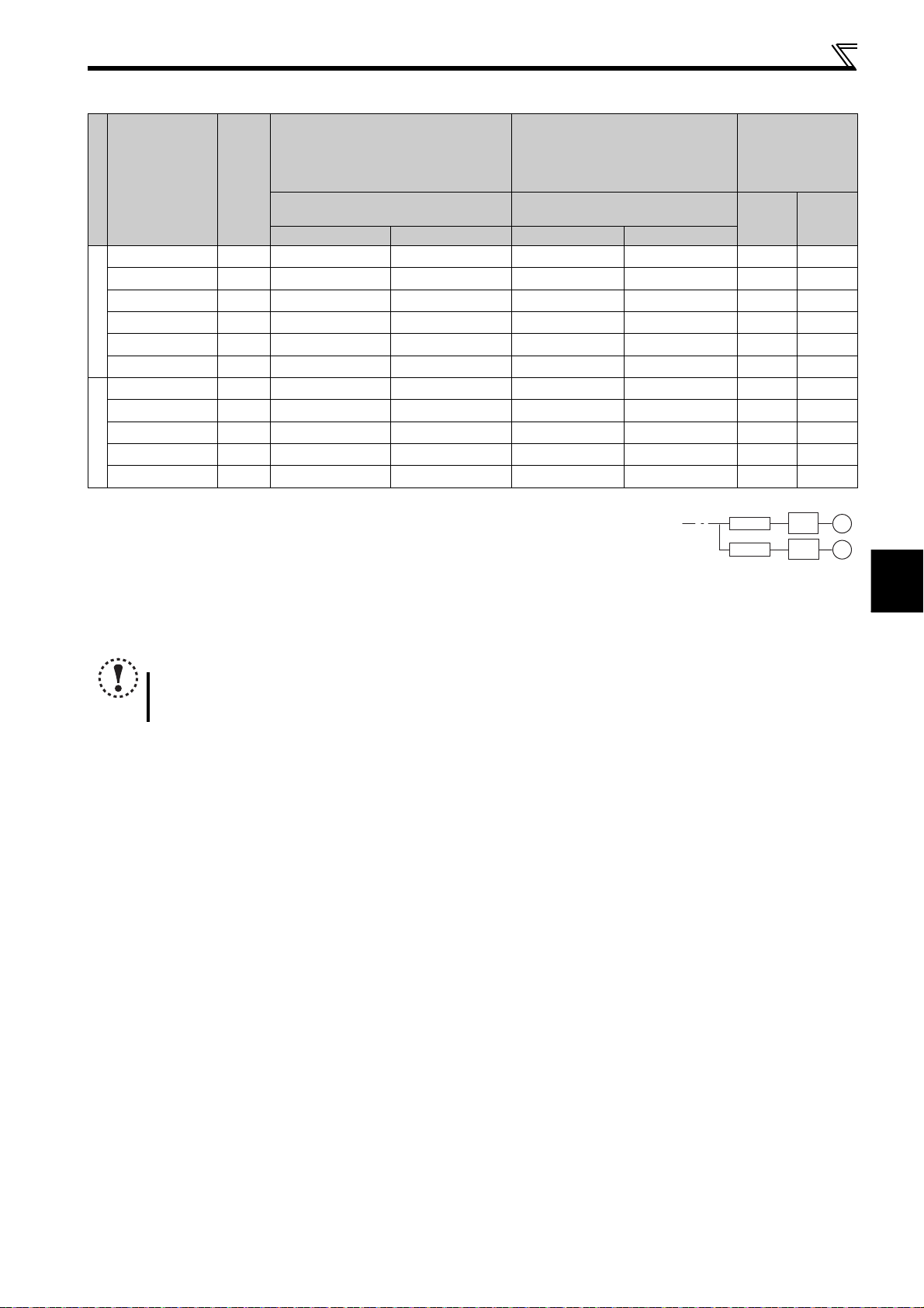
(2) Other PM motor (IPM or SPM)
MCCB
Drive
unit
Drive
unit
MCCB
M
M
Drive unit and peripheral devices
Molded Case Circuit Breaker
(MCCB) or
Input Side Magnetic Contactor Reactor
Power factor improving (AC or DC)
reactor connection
FR-HAL FR-HEL
Applicable Drive
Unit Model
Vol tage
Motor
Output
(kW)
Earth Leakage Circuit Breaker
(ELB)
(NF or NV type)
Power factor improving (AC or DC)
reactor connection
Without With Without With
FR-D720-0.2K-G 0.2 5A 5A S-T10 S-T10 0.4K 0.4K
FR-D720-0.4K-G 0.4 5A 5A S-T10 S-T10 0.4K 0.4K
FR-D720-0.75K-G 0.75 10A 5A S-T10 S-T10 0.75K 0.75K
FR-D720-1.5K-G 1.5 15A 10A S-T10 S-T10 1.5K 1.5K
200V class
FR-D720-2.2K-G 2.2 20A 15A S-T10 S-T10 2.2K 2.2K
FR-D720-3.7K-G 3.7 30A 30A S-T21 S-T10 3.7K 3.7K
FR-D740-0.4K-G 0.4 5A 5A S-T10 S-T10 H0.4K H0.4K
FR-D740-0.75K-G 0.75 5A 5A S-T10 S-T10 H0.75K H0.75K
FR-D740-1.5K-G 1.5 10A 10A S-T10 S-T10 H1.5K H1.5K
FR-D740-2.2K-G 2.2 15A 10A S-T10 S-T10 H2.2K H2.2K
400V class
FR-D740-3.7K-G 3.7 20A 15A S-T10 S-T10 H3.7K H3.7K
Select an MCCB according to the power supply capacity.
Install one MCCB per drive unit.
For the use in the United States or Canada, refer to "Instructions for UL and cUL" in the Instruction Manual (Basic),
and select an appropriate fuse or molded case circuit breaker (MCCB).
Magnetic contactor is selected based on the AC-1 class. The electrical durability of magnetic contactor is 500,000 times. When the magnetic contactor is
used for emergency stop during motor driving, the electrical durability is 25 times.
If using an MC for emergency stop during motor driving, select an MC regarding the drive unit input side current as JEM1038-AC-3 class rated current.
The power factor may be slightly lower.
NOTE
Select a MCCB and a magnetic contactor according to the drive unit model, and cable and reactor according to the motor output.
When the breaker on the drive unit input side trips, check for the wiring fault (short circuit), damage to internal parts of the drive unit,
etc. Identify the cause of the trip, then remove the cause and power ON the breaker.
5
Removal and reinstallation of the cover
1)
Mounting screw
2)
1.3 Removal and reinstallation of the cover
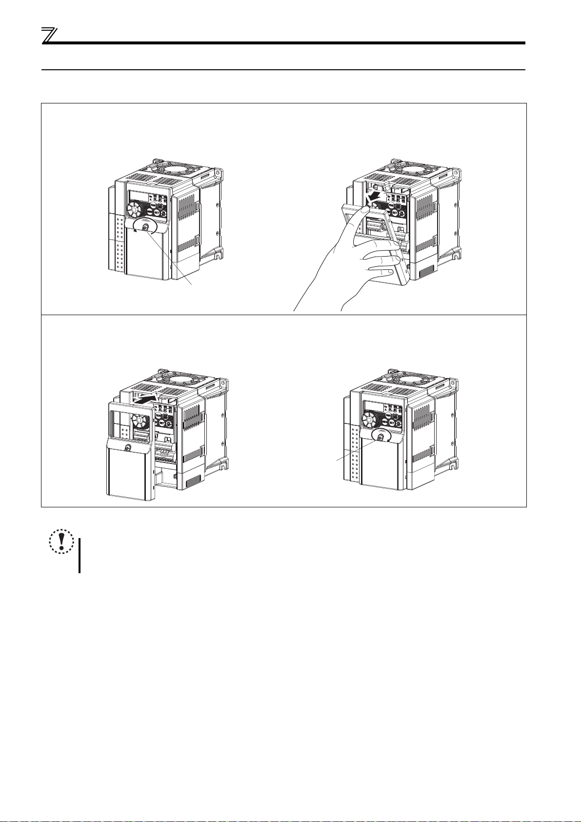
1.3.1 Front cover
Removal (Example of FR-D720-1.5K-G)
1) Loosen the mounting screws of the front cover. (The screws cannot be removed.)
2) Remove the front cover by pulling it like the direction of arrow.
Reinstallation (Example of FR-D720-1.5K-G)
1) Place the front cover in front of the drive unit, and install it straight.
2) Tighten the mounting screws on the front cover.
1) 2)
Mounting screw
NOTE
Fully make sure that the front cover has been reinstalled securely.
The same serial number is printed on the capacity plate of the front cover and the rating plate of the drive unit. Since
these plates have the same serial numbers, always reinstall the removed cover onto the original drive unit.
6
1
OUTLINE
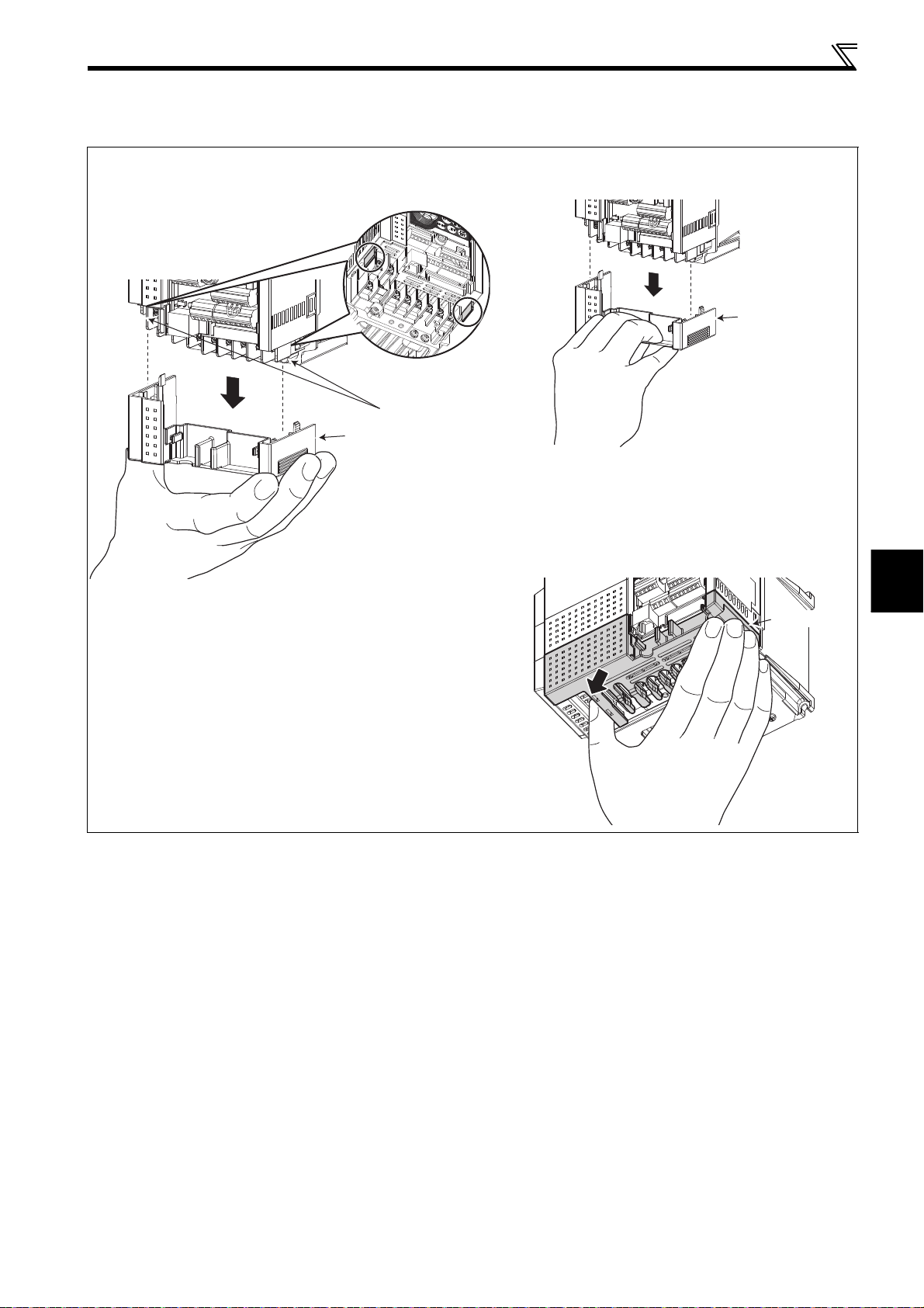
1.3.2 Wiring cover
r
Wiring cover
Removal and reinstallation
Removal and reinstallation of the cover
Hold the side of the wiring cover, and pull it downward for
removal.
To reinstall, fit the cover to the drive unit along the guides.
Guide
Wiring cover
Example of FR-D720-1.5K-G
Also pull the wiring cover downward by holding a
frontal part of the wiring cover.
Wiring cove
Example of FR-D720-1.5K-G
See below diagram for wiring cover of FR-D720-3.7K-
G. Hold the dent of the wiring cover (marked with an
arrow) with thumb and the side with other fingers and
pull downward for removal.
7

Installation of the drive unit and enclosure design
1.4 Installation of the drive unit and enclosure design
When a drive unit enclosure is to be designed and manufactured, heat generated by contained equipment, etc., the
environment of an operating place, and others must be fully considered to determine the enclosure structure, size and
equipment layout. The drive unit unit uses many semiconductor devices. To ensure higher reliability and long period of
operation, operate the drive unit in the ambient environment that completely satisfies the equipment specifications.
1.4.1 Drive unit installation environment
As the drive unit installation environment should satisfy the standard specifications indicated in the following table, operation
in any place that does not meet these conditions not only deteriorates the performance and life of the drive unit, but also
causes a failure. Refer to the following points and take adequate measures.
Environmental standard specifications of drive unit
Item Description
Surrounding air
temperature
Ambient humidity 90%RH or less (non-condensing)
Atmosphere Indoors (free from corrosive gas, flammable gas, oil mist, dust and dirt)
Maximum altitude 1,000m or less
Vibration
(1) Temperature
The permissible surrounding air temperature of the drive unit is between -10°C
within this temperature range. Operation outside this range will considerably shorten the service lives of the semiconductors,
parts, capacitors and others. Take the following measures so that the surrounding air temperature of the drive unit falls within
the specified range.
1) Measures against high temperature
Use a forced ventilation system or similar cooling system. (Refer to page 10.)
Install the panel in an air-conditioned electrical chamber.
Block direct sunlight.
Provide a shield or similar plate to avoid direct exposure to the radiated heat and wind of a heat source.
Ventilate the area around the panel well.
°C to +50°C
-10
5.9m/s
(non-freezing)
2
or less at 10 to 55Hz (directions of X, Y, Z axes)
and +50°C
. Always operate the drive unit
2) Measures against low temperature
Provide a space heater in the enclosure.
Do not power OFF the drive unit. (Keep the start signal of the drive unit OFF.)
3) Sudden temperature changes
Select an installation place where temperature does not change suddenly.
Avoid installing the drive unit near the air outlet of an air conditioner.
If temperature changes are caused by opening/closing of a door, install the drive unit away from the door.
(2) Humidity
Normally operate the drive unit within the 45 to 90% range of the ambient humidity. Too high humidity will pose problems of
reduced insulation and metal corrosion. On the other hand, too low humidity may produce a spatial electrical breakdown. The
insulation distance specified in JEM1103 "Control Equipment Insulator" is defined as humidity 45 to 85%.
1) Measures against high humidity
Make the panel enclosed, and provide it with a hygroscopic agent.
Take dry air into the enclosure from outside.
Provide a space heater in the enclosure.
2) Measures against low humidity
What is important in fitting or inspection of the unit in this status is to discharge your body (static electricity)
beforehand and keep your body from contact with the parts and patterns, besides blowing air of proper humidity into
the enclosure from outside.
3) Measures against condensation
Condensation may occur if frequent operation stops change the in-enclosure temperature suddenly or if the outside-
air temperature changes suddenly.
Condensation causes such faults as reduced insulation and corrosion.
Take the measures against high humidity in 1).
Do not power OFF the drive unit. (Keep the start signal of the drive unit OFF.)
8

1
OUTLINE
Installation of the drive unit and enclosure design
(3) Dust, dirt, oil mist
Dust and dirt will cause such faults as poor contact of contact points, reduced insulation or reduced cooling effect due to
moisture absorption of accumulated dust and dirt, and in-enclosure temperature rise due to clogged filter. In the atmosphere
where conductive powder floats, dust and dirt will cause such faults as malfunction, deteriorated insulation and short circuit in
a short time.
Since oil mist will cause similar conditions, it is necessary to take adequate measures.
Countermeasures
Place in a totally enclosed enclosure.
Take measures if the in-enclosure temperature rises. (Refer to page 10.)
Purge air.
Pump clean air from outside to make the in-enclosure pressure higher than the outside-air pressure.
(4) Corrosive gas, salt damage
If the drive unit is exposed to corrosive gas or to salt near a beach, the printed board patterns and parts will corrode or the
relays and switches will result in poor contact.
In such places, take the measures given in Section 3.
(5) Explosive, flammable gases
As the drive unit is non-explosion proof, it must be contained in an explosion proof enclosure. In places where explosion may
be caused by explosive gas, dust or dirt, an enclosure cannot be used unless it structurally complies with the guidelines and
has passed the specified tests. This makes the enclosure itself expensive (including the test charges). The best way is to
avoid installation in such places and install the drive unit in a non-hazardous place.
(6) Highland
Use the drive unit at the altitude of within 1000m. If it is used at a higher place, it is likely that thin air will reduce the cooling
effect and low air pressure will deteriorate dielectric strength.
(7) Vibration, impact
The vibration resistance of the drive unit is up to 5.9m/s2 at 10 to 55Hz frequency and 1mm amplitude for the directions of X,
Y, Z axes. Vibration or impact, if less than the specified value, applied for a long time may make the mechanism loose or
cause poor contact to the connectors.
Especially when impact is imposed repeatedly, caution must be taken as the part pins are likely to break.
Countermeasures
Provide the panel with rubber vibration isolators.
Strengthen the structure to prevent the enclosure from resonance.
Install the enclosure away from sources of vibration.
9
Installation of the drive unit and enclosure design
Drive
unit
Heat pipe
Drive
unit
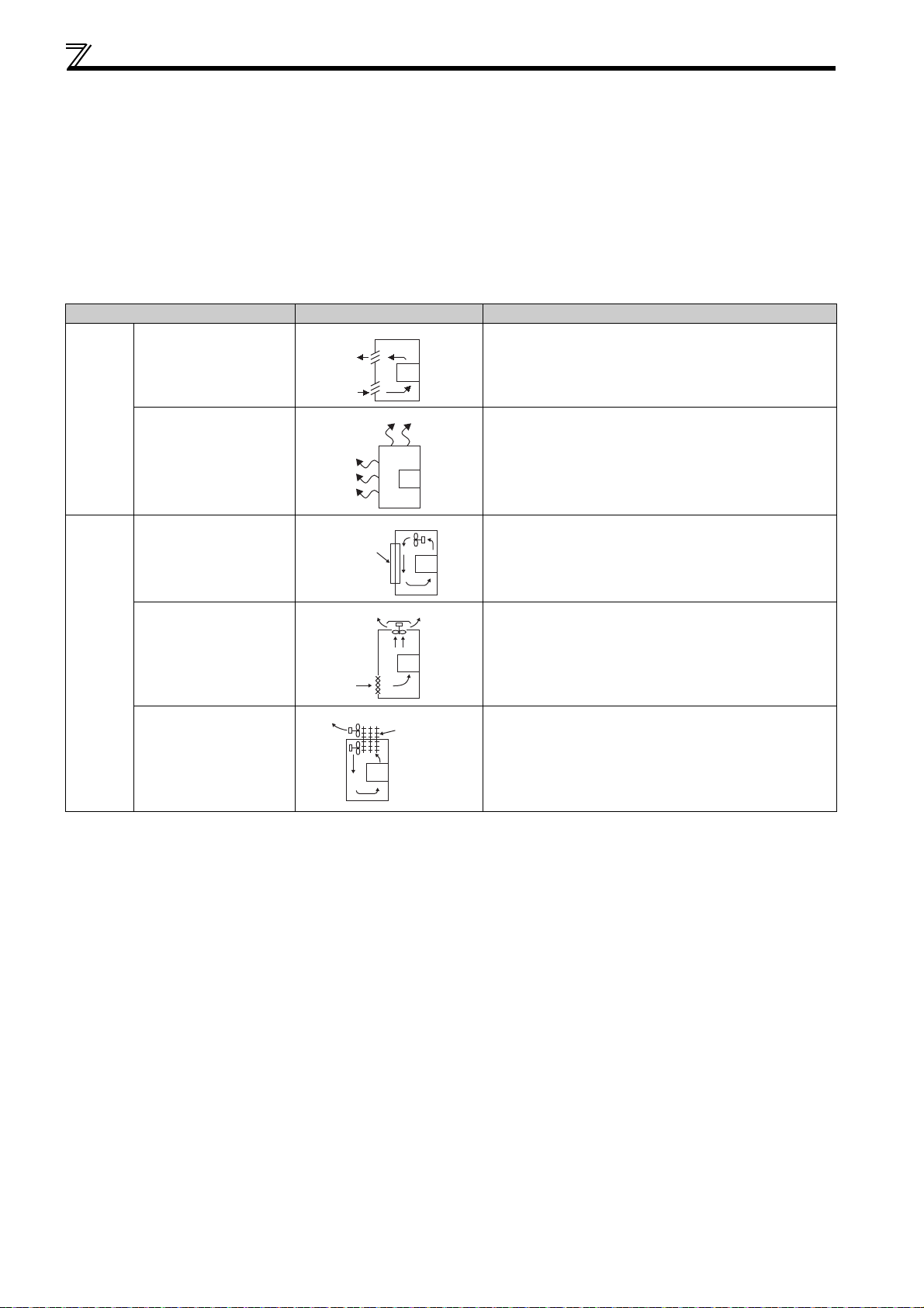
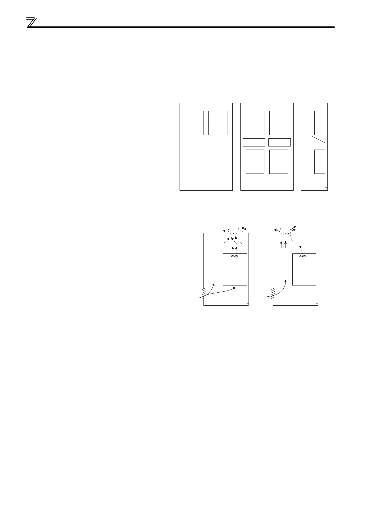
1.4.2 Cooling system types for drive unit enclosure
From the enclosure that contains the drive unit, the heat of the drive unit and other equipment (transformers, lamps, resistors,
etc.) and the incoming heat such as direct sunlight must be dissipated to keep the in-enclosure temperature lower than the
permissible temperatures of the in-enclosure equipment including the drive unit.
The cooling systems are classified as follows in terms of the cooling calculation method.
1) Cooling by natural heat dissipation from the enclosure surface (totally enclosed type)
2) Cooling by heat sink (aluminum fin, etc.)
3) Cooling by ventilation (forced ventilation type, pipe ventilation type)
4) Cooling by heat exchanger or cooler (heat pipe, cooler, etc.)
Cooling System Enclosure Structure Comment
Natural
cooling
Forced
cooling
Natural ventilation
(enclosed, open type)
Natural ventilation
(totally enclosed type)
Heatsink cooling
Forced ventilation
Heatsink
Drive
unit
Drive
unit
Drive
unit
Low in cost and generally used, but the enclosure size
increases as the drive unit capacity increases. For relatively
small capacities.
Being a totally enclosed type, the most appropriate for hostile
environment having dust, dirt, oil mist, etc. The enclosure size
increases depending on the drive unit capacity.
Having restrictions on the heatsink mounting position and
area, and designed for relative small capacities.
For general indoor installation. Appropriate for enclosure
downsizing and cost reduction, and often used.
Heat pipe Totally enclosed type for enclosure downsizing.
10
1
OUTLINE
Drive unit placement
Front cover
Front cover
Wiring cover Wiring cover
FR-D720-0.2K to 0.75K-G FR-D720-1.5K to 3.7K-G
FR-D740-0.4K to 3.7K-G
10cm or more
10cm or more
Measurement
position
Measurement
position
5cm
5cm
5cm
-10 C to +50 C
(non-freezing)
1cm or
more
∗
1cm or
more
∗
1cm or
more
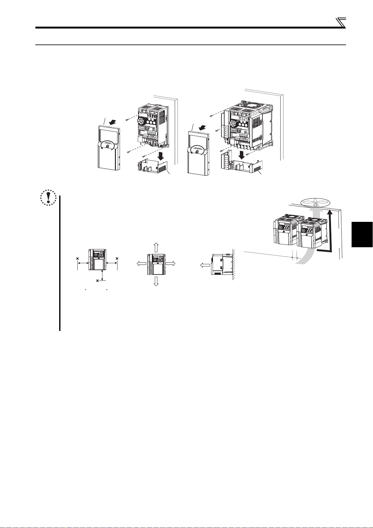
1.5 Drive unit placement
Enclosure surface mounting
Remove the front cover and wiring cover to mount the drive unit to the surface. (Remove the covers in the directions of the
arrows.)
NOTE
When encasing multiple drive units, install them in parallel as a
cooling measure.
Install the drive unit vertically.
For heat dissipation and maintenance, allow minimum clearance
shown in the figures below from the drive unit to the other devices
and to the inner surface of the enclosure.
Refer to the clearance
shown on the left.
Vertical
* When using the drive units at the surrounding air temperature of 40C or less, the drive units can be installed without any clearance between
them (0cm clearance).
When designing or building an enclosure for the drive unit, carefully consider influencing factors such as heat
generation of the contained devices and the operating environment.
11
Drive unit placement
Guide Guide
Enclosure Enclosure
Guide
(a) Horizontal arrangement
(b) Vertical arrangement
Drive
unit
Drive
unit
Drive
unit
Drive
unit
Drive
unit
Drive
unit
1.5.1 Installation precautions
(1) Above drive unit
Heat is blown up from inside the drive unit by the small fan built in the unit. Any equipment placed above the drive unit should
be heat resistant.
(2) Arrangement of multiple drive units
When multiple drive units are placed in the same
enclosure, generally arrange them horizontally as shown
in the right figure (a). When it is inevitable to arrange
them vertically to minimize space, take such measures as
to provide guides since heat from the bottom drive units
can increase the temperatures in the top drive units,
causing drive unit failures.
When mounting multiple drive units, fully take caution not
to make the surrounding air temperature of the drive unit
higher than the permissible value by providing ventilation
and increasing the enclosure size.
Arrangement of multiple drive units
(3) Arrangement of ventilation fan and drive unit
Heat generated in the drive unit is blown up from the bottom of
the unit as warm air by the cooling fan. When installing a
ventilation fan for that heat, determine the place of ventilation
fan installation after fully considering an air flow. (Air passes
through areas of low resistance. Make an airway and airflow
plates to expose the drive unit to cool air.)
Drive unit Drive unit
<Good example> <Bad example>
Arrangement of ventilation fan and drive unit
12

2 WIRING
This chapter describes the basic "WIRING" for use of this
product.
Always read the instructions before using the equipment.
2.1 Wiring............................................................................................. 14
2.2 Main circuit terminal specifications............................................ 15
2.3 Control circuit specifications ...................................................... 18
2.4 Connection of stand-alone option unit....................................... 27
1
2
3
4
5
13
6
7
Wiring
2.1 Wiring
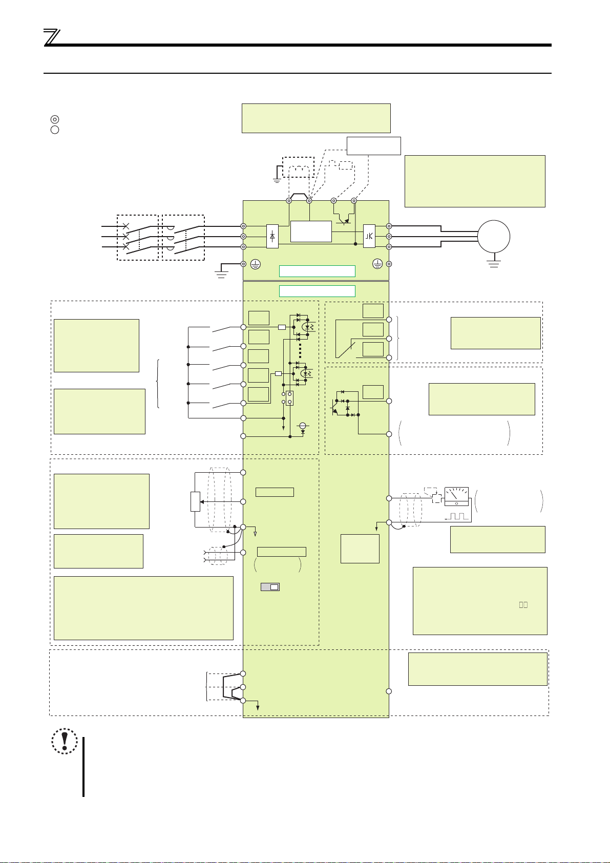
2.1.1 Terminal connection diagram
Sink logic
Main circuit terminal
Control circuit terminal
MCCB MC
Three-phase
AC power
supply
Earth
(Ground)
Control input signals (No voltage input allowed)
The function of these
terminals can be
changed to the reset
signal, etc. with the input
terminal assignment
(Pr. 178 to Pr. 182).
Multi-speed selection
*2 When using terminals
PC-SD as a 24VDC
power supply, take care
not to short across
terminals PC and SD.
(Common for external power supply transistor)
Forward
rotation start
Reverse
rotation start
High
speed
Middle
speed
Low
speed
Contact input common
24VDC power supply
*1. DC reactor (FR-HEL)
When connecting a DC reactor, remove the
jumper across P1 and P/+
Earth
*1
(Ground)
Jumper
R
*6
PR
P1 P/+
R/L1
S/L2
T/L3
Inrush current
limit circuit
Main circuit
Control circuit
STF
STR
RH
RM
PC
RL
SD
*2
SOURCE
SINK
24V
N/-
Brake unit
(Option)
U
V
W
C
B
A
RUN
SE
*6 Brake resistor (FR-ABR, MRS type, MYS
type)
Install a thermal relay to prevent an
overheat and burnout of the brake resistor.
(The brake resistor cannot be connected
to the 0.2K.)
Motor
M
Earth (Ground)
Relay output
Terminal functions vary
Relay output
(Fault output)
by Pr. 192 A,B,C terminal
function selection
Open collector output
Terminal functions vary by
Running
Pr. 190 RUN terminal function
selection
Open collector output common
Sink/source common
Speed setting signals (Analog)
*4
Terminal 4
input
(Current
input)
3
2
1
(+)
(-)
*3
Terminal input specifications
can be changed by analog
input specifications
switchover (Pr. 73).
Terminal 10 and terminal 2
are used as PTC input
terminal (Pr. 561).
*4 It is recommended to
use 2W1kΩ when the
speed setting signal is
changed frequently.
*5 Terminal input specifications can be changed by analog
input specifications switchover (Pr. 267). Set the
voltage/current input switch in the "V" position to select
voltage input (0 to 5V/0 to10V) and "I" (initial value) to
select current input (4 to 20mA).
To use terminal 4 (initial setting is current input), set "4"
in any of Pr. 178 to Pr. 182 (input terminal function
selection) to assign the function, and turn ON AU signal.
Speed
setting
potentiometer
1/2W1kΩ
For manufacturer *9
NOTE
To prevent a malfunction caused by noise, separate the signal cables more than 10cm from the power cables. Also
separate the main circuit wire of the input side and the output side.
After wiring, wire offcuts must not be left in the drive unit.
Wire offcuts can cause an alarm, failure or malfunction. Always keep the drive unit clean. When drilling mounting
holes in an enclosure etc., take caution not to allow chips and other foreign matter to enter the drive unit.
10(+5V)
2 0 to 5VDC
(0 to 10VDC)
*3
5(Analog common)
4 4 to 20mADC
0 to 5VDC
0 to 10VDC
VI
Voltage/current
input switch
*5
S1
S2
SC
Calibration resistor
FM
SD
*7
PU
connector
*5
*8
For manufacturer *9
SO
*8 Operation and parameter setting can be
done from the parameter unit
(FR-PU07) and the enclosure surface
operation panel (FR-PA07).
(Use the option cable (FR-CB2 ).)
RS-485 communication can be utilized
from a personal computer and other
devices.
*9 The terminals S1, S2, SC, and SO are for
manufacturer setting. Do not remove the
shortening wires across the terminals S1
and SC and the terminals S2 and SC.
Indicator
(Speed meter, etc.)
+
-
Moving-coil type
1mA full-scale
*7 It is not necessary when
calibrating the indicator
from the operation panel.
14
2
WIRING
Main circuit terminal specifications
r
2.2 Main circuit terminal specifications
2.2.1 Specification of main circuit terminal
Drive unit
Ter mina l
Symbol
R/L1,
S/L2,
T/L3
U, V, W Drive unit output Connect a PM motor. 15
P/+, PR Brake resistor connection
P/+, N/- Brake unit connection
P/+, P1 DC reactor connection
Ter m i n a l Name Description
Connect to the commercial power supply.
AC power input
Earth (Ground) For earthing (grounding) the drive unit chassis. Must be earthed (grounded). 17
Keep these terminals open when using the high power factor converter (FR-HC2)
or power regeneration common converter (FR-CV).
Connect a brake resistor (FR-ABR, MRS type, MYS type) across terminals P/+ and
PR. (The brake resistor cannot be connected to the 0.2K.)
Connect the brake unit (FR-BU2), power regeneration common converter (FR-
CV) or high power factor converter (FR-HC2).
Remove the jumper across terminals P/+ and P1 and connect a DC reactor.
When a DC reactor is not connected, the jumper across terminals P/+ and P1
should not be removed.
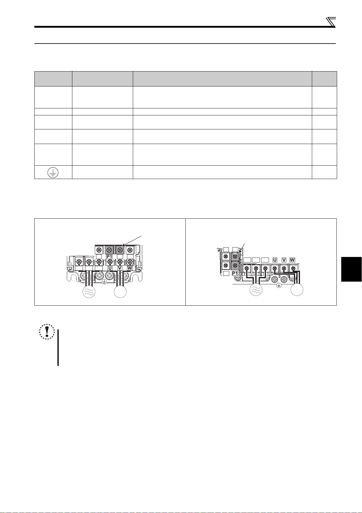
2.2.2 Terminal arrangement of the main circuit terminal, power supply and the motor wiring
Refer to
Page
15
27
29
33
FR-D720-0.2K to 0.75K-G FR-D720-1.5K to 3.7K-G
FR-D740-0.4K to 3.7K-G
Jumpe
N/-
P/+
N/-
R/L1 S/L2 T/L3
P/+ PR
PR
M
MotorPower supply
NOTE
Make sure the power cables are connected to the R/L1, S/L2, and T/L3. (Phase need not be matched.) Never connect
the power cable to the U, V, and W of the drive unit. Doing so will damage the drive unit.
Connect the motor to U, V, W. Turning ON the forward rotation switch (signal) at this time rotates the motor
counterclockwise when viewed from the load shaft. The rotation direction of the output shaft may differ depending on
the reduction gear. Check the motor specifications.
Jumper
R/L1 S/L2 T/L3
Power supply
M
Motor
15
Main circuit terminal specifications
3 × wire resistance[mΩ/m] × wiring distance[m] × current[A]
1000
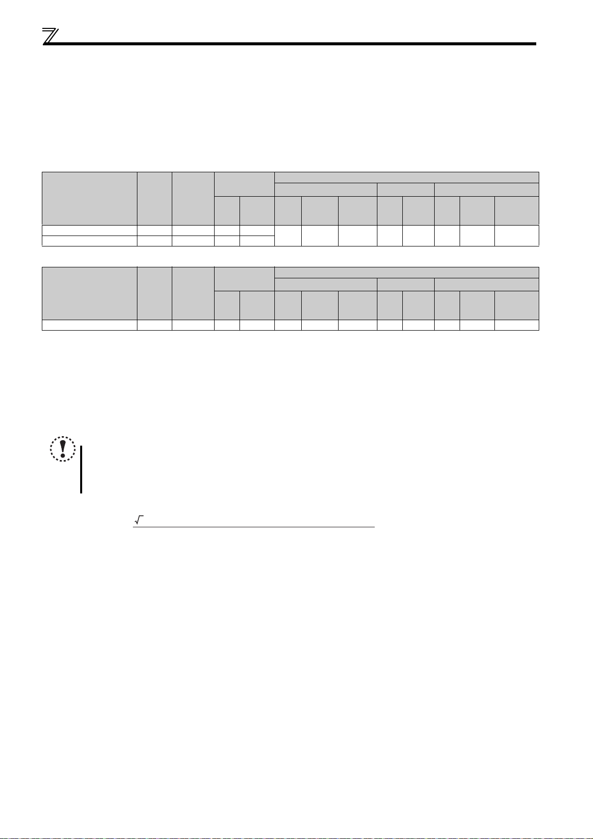
2.2.3 Cables and wiring length
(1) Applied wire size
Select the recommended cable size to ensure that a voltage drop will be 2% or less.
If the wiring distance is long between the drive unit and motor, a main circuit cable voltage drop will cause the motor torque to
decrease especially at the output of a low speed.
The following table indicates a selection example for the wiring length of 20m.
Three-phase 200V class (when input power supply is 220V)
Applicable Drive Unit
Model
FR-D720-0.2K to 0.75K-G M3.5 1.2 2-3.5 2-3.5
FR-D720-1.5K to 3.7K-G M4 1.5 2-4 2-4
Ter minal
Screw
Size
Tightening
Tor que
N
·
m
Crimp
Ter minal
R/L1
S/L2
T/L3
U, V, W
HIV Cables, etc. (mm2)
R/L1
U, V, W
S/L2
T/L3
2 2 2 14 14 2.5 2.5 2.5
Earthing
(grounding)
cable
Three-phase 400V class (when input power supply is 440V)
Applicable Drive Unit
Model
FR-D740-0.4K to 3.7K-G M4 1.5 2-4 2-4 2 2 2 14 14 2.5 2.5 2.5
The cable size is that of the cable (HIV cable (600V class 2 vinyl-insulated cable) etc.) with continuous maximum permissible temperature of 75°C. Assumes
that the surrounding air temperature is 50°C or less and the wiring distance is 20m or less.
The recommended cable size is that of the cable (THHW cable) with continuous maximum permissible temperature of 75°C. Assumes that the surrounding
air temperature is 40°C or less and the wiring distance is 20m or less. (For the use in the United States or Canada, refer to "Instructions for UL and cUL" in
the Instruction Manual (Basic).)
The recommended cable size is that of the cable (PVC cable) with continuous maximum permissible temperature of 70°C. Assumes that the surrounding air
temperature is 40°C or less and the wiring distance is 20m or less. (Selection example for use mainly in Europe.)
The terminal screw size indicates the terminal size for R/L1, S/L2, T/L3, U, V, W, PR, P/+, N/-, P1 and a screw for earthing (grounding).
Ter minal
Screw
Size
Tightening
Tor que
N
·
m
Crimp
Ter minal
R/L1
S/L2
T/L3
U, V, W
HIV Cables, etc. (mm2)
R/L1
S/L2
T/L3
U, V, W
Earthing
(grounding)
cable
Cable Size
AWG
R/L1
U, V, W
S/L2
T/L3
Cable Size
AWG
R/L1
U, V, W
S/L2
T/L3
PVC Cables, etc. (mm2)
R/L1
U, V, W
S/L2
T/L3
PVC Cables, etc. (mm2)
R/L1
U, V, W
S/L2
T/L3
Earthing
(grounding)
cable
Earthing
(grounding)
cable
NOTE
Tighten the terminal screw to the specified torque. A screw that has been tightened too loosely can cause a short
circuit or malfunction. A screw that has been tightened too tightly can cause a short circuit or malfunction due to the
unit breakage.
Use crimp terminals with insulation sleeve to wire the power supply and motor.
The line voltage drop can be calculated by the following formula:
Line voltage drop [V]=
Use a larger diameter cable when the wiring distance is long or when it is desired to decrease the voltage drop (torque
reduction) in the low speed range.
16
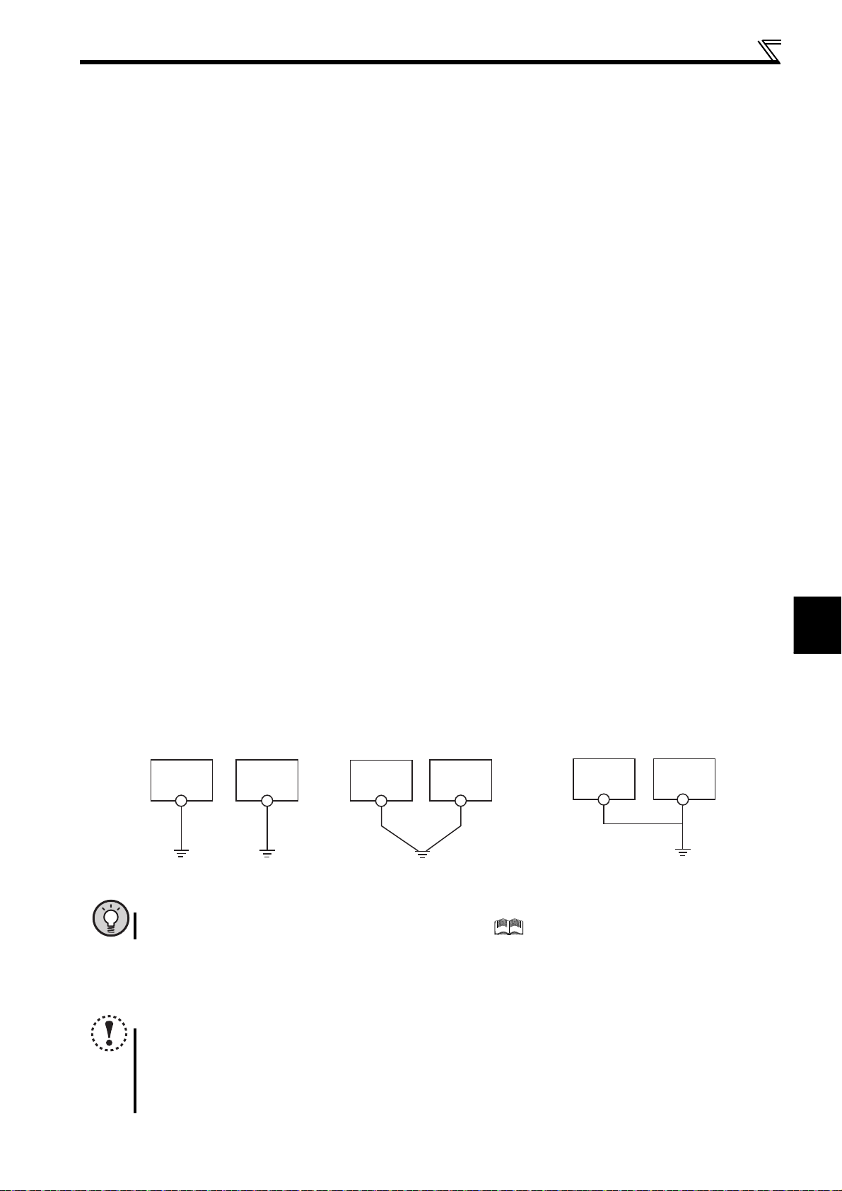
2
WIRING
Main circuit terminal specifications
Drive unit
Other
equipment
(I)Independent earthing (grounding).......Best
Drive unit
Other
equipment
(III)Common earthing (grounding) cable.......Not allowed
(2) Earthing (Grounding) precautions
Always earth (ground) the motor and drive unit.
1) Purpose of earthing (grounding)
Generally, an electrical apparatus has an earthing (grounding) terminal, which must be connected to the ground before
use.
An electrical circuit is usually insulated by an insulating material and encased. However, it is impossible to manufacture
an insulating material that can shut off a leakage current completely, and actually, a slight current flow into the case.
The purpose of earthing (grounding) the case of an electrical apparatus is to prevent operator from getting an electric
shock from this leakage current when touching it.
To avoid the influence of external noises, this earthing (grounding) is important to audio equipment, sensors, computers
and other apparatuses that handle low-level signals or operate very fast.
2) Earthing (grounding) methods and earthing (grounding) work
As described previously, earthing (grounding) is roughly classified into an electrical shock prevention type and a noise-
affected malfunction prevention type. Therefore, these two types should be discriminated clearly, and the following
work must be done to prevent the leakage current having the drive unit's high frequency components from entering the
malfunction prevention type earthing (grounding):
(a)If possible, use (l) independent earthing (grounding) in figure below for the drive unit. If independent earthing
(grounding) is not available, use (ll) common earthing (grounding) in the figure below where the drive unit is
connected with the other equipment at an earthing (grounding) point.
The (lll) common earthing (grounding) cable as in the figure below, which drive unit shares a common earthing
(grounding) cable with the other equipment, must be avoided.
A leakage current including many high frequency components flows in the earthing (grounding) cables of the drive
unit and drive unit-driven motor. Therefore, use the independent earthing (grounding) and separate the earthing
(grounding) cable of the drive unit from equipment sensitive to EMI.
In a high building, it may be effective to use the EMI prevention type earthing (grounding) connecting to an iron
structure frame, and electric shock prevention type earthing (grounding) with the independent earthing (grounding)
together.
(b)This drive unit must be earthed (grounded). Earthing (Grounding) must conform to the requirements of national and
local safety regulations and electrical codes. (NEC section 250, IEC 61140 class 1 and other applicable standards).
Use an neutral-point earthed (grounded) power supply for 400V class drive unit in compliance with EN standard.
(c)Use the thickest possible earthing (grounding) cable. The earthing (grounding) cable size should be no less than the
size indicated in the table on page 16.
(d)The earthing (grounding) point should be as close as possible to the drive unit, and the earthing (grounding) cable
length should be as short as possible.
(e)Run the earthing (grounding) cable as far away as possible from the I/O wiring of equipment sensitive to noises and
run them in parallel in the minimum distance.
POINT
To be compliant with the EU Directive (Low Voltage Directive), refer to the Instruction Manual (Basic).
(3) Total wiring length
Connect a PM motor within the total wiring length of 30m.
Use one PM motor for one drive unit. Multiple PM motors cannot be connected to a drive unit.
NOTE
Especially for long-distance wiring, the drive unit may be affected by a charging current caused by the stray
Drive unit
(II)Common earthing (grounding).......Good
capacitances of the wiring, leading to a malfunction of the overcurrent protective function or the stall prevention
function, or a malfunction or fault of the equipment connected on the drive unit's output side. If malfunction of stall
prevention function occurs, increase the stall level. (Refer to page 83 for Pr. 22 Stall prevention operation level and Pr. 156 Stall
prevention operation selection.)
Other
equipment
17
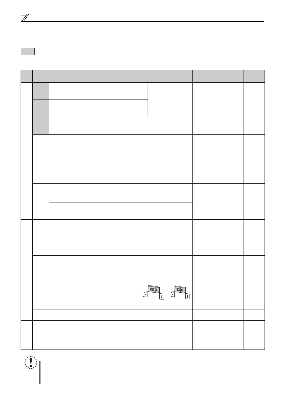
Control circuit specifications
Voltage input
Current input
(initial status)
2.3 Control circuit specifications
2.3.1 Control circuit terminal
indicates that terminal functions can be selected using Pr. 178 to Pr. 182, Pr. 190, Pr. 192 (I/O terminal function selection).
(Refer to page 117.)
(1) Input signal
Term inal
Typ e
Symbol
STF Forward rotation start
STR Reverse rotation start
RH,
RM,
RL
SD
Contact input
PC
10
2 Speed setting (voltage)
Speed setting
4 Speed setting (current)
5 Speed setting common
10
2
Thermistor
Terminal Name Description Rated Specifications
Turn ON the STF signal to
start forward rotation and
turn it OFF to stop.
Turn ON the STR signal to
start reverse rotation and
turn it OFF to stop.
Multi-speed selection
Contact input common
(sink) (initial setting)
External transistor
common (source)
24VDC power supply
common
External transistor
common (sink)
(initial setting)
Contact input common
(source)
24VDC power supply Can be used as 24VDC 0.1A power supply.
Speed setting power
supply
PTC thermistor input
Multi-speed can be selected according to the
combination of RH, RM and RL signals.
Common terminal for contact input terminal (sink logic)
and terminal FM.
Connect this terminal to the power supply common
terminal of a transistor output (open collector output)
device, such as a programmable controller, in the
source logic to avoid malfunction by undesirable
currents.
Common output terminal for 24VDC 0.1A power supply
(PC terminal).
Isolated from terminals 5 and SE.
Connect this terminal to the power supply common
terminal of a transistor output (open collector output)
device, such as a programmable controller, in the sink
logic to avoid malfunction by undesirable currents.
Common terminal for contact input terminal (source
logic).
Used as power supply when connecting potentiometer
for speed setting from outside of the drive unit.
(Refer to Pr. 73 Analog input selection.)
Inputting 0 to 5VDC (or 0 to 10V) provides the maximum
rotation speed at 5V (10V) and makes input and output
proportional. Use
input (initial setting) and 0 to 10VDC.
Inputting 4 to 20mADC (or 0 to 5V, 0 to 10V) provides
the maximum rotation speed at 20mA and makes input
and output proportional. This input signal is valid only
when the AU signal is ON (terminal 2 input is invalid).
Use Pr. 267 to switch
from among input 4 to
20mA (initial setting), 0
to 5VDC and 0 to
10VDC. Set the voltage/
current input switch in
the "V" position to select
voltage input (0 to 5V/0 to 10V).
Speed setting signal (terminal 2, 4) common terminal.
Do not earth (ground).
For connecting PTC thermistor output.
When PTC thermistor protection is valid (Pr. 561
"9999"), terminal 2 is not available for speed setting.
Pr. 73
When the STF and STR
signals are turned ON
simultaneously, the stop
command is given.
to switch between input 0 to 5VDC
Input resistance 4.7k
Voltage at opening
21 to 26VDC
Current at short-circuited
4 to 6mADC
——
Power supply voltage range
22 to 26.5VDC
permissible load current
100mA
5.0V0.2VDC
permissible load current
10mA
Input resistance10k1k
Permissible maximum
voltage 20VDC
Current input:
Input resistance 2495
Maximum permissible
current 30mA
Voltage input:
Input resistance10k 1k
Permissible maximum
voltage 20VDC
——
Adaptive PTC thermistor
specification
Heat detection resistance :
to 30k (Set by
500
)
561
Pr.
Refer to
Page
121
89
21
147
147
147
101
18
NOTE
Set Pr. 267 and a voltage/current input switch correctly, then input analog signals in accordance with the settings.
Applying a voltage with voltage/current input switch in "I" position (current input is selected) or a current with switch in
"V" position (voltage input is selected) could cause component damage of the drive unit or analog circuit of output
devices. (Refer to page 147 for details.)
2
WIRING
(2) Output signal
Ter min al
Typ e
Symbol
A, B, C
Relay
RUN Drive unit running
Open collector
SE
FM For meter
Pulse
Terminal Name Description Rated Specifications
Relay output (fault
output)
Open collector
output common
Control circuit specifications
Refer to
Page
1 changeover contact output indicates that the drive unit
protective function has activated and the output stopped.
Fault: discontinuity across B-C (continuity across A-C),
Normal: continuity across B-C (discontinuity across A-C)
Switched Low when the drive unit rotation speed is equal to
or higher than the 1r/min.
Switched High during stop or DC injection brake operation.
(Low is when the open collector output transistor is ON
(conducts). High is when the transistor is OFF (does not
conduct).)
Common terminal of terminal RUN. — —
Select one e.g. rotation speed from monitor items.
Not output during drive unit reset. Not output during drive
unit reset.
The output signal is proportional to the magnitude of the
corresponding monitoring item.
Use Pr. 55 and Pr. 56 to set full-scale values for monitoring
the rotation speed and the output current. (Refer to page
139.)
Contact capacity:230VAC
0.3A
(power factor =0.4)
30VDC 0.3A
Permissible load 24VDC
(maximum 27VDC) 0.1A
(a voltage drop is 3.4V
maximum when the signal is
ON)
Permissible load current
1mA
1440 pulses/s at 3000r/min
123
123
134
(3) Communication
Typ e
Ter minal
Symbol
— PU connector
Communication
NOTE
The terminals S1, S2, SC, and SO are for manufacturer setting. Do not connect anything to these. Doing so may cause a
drive unit failure.
Do not remove the shortening wires across the terminals S1 and SC and the terminals S2 and SC. Removing either
shortening wire disables the drive unit operation.
Terminal Name Description
With the PU connector, communication can be made through RS-485.
Conforming standard: EIA-485 (RS-485)
Transmission format: Multidrop link
Communication speed: 4800 to 38400bps
Overall length: 500m
Refer to
Page
181
19
 Loading...