

Mitsubishi Electric FR-D720-008, FR-D740-012, FR-D720S-008, FR-D710W-008 Installation Manuallines

INVERTER
FR-D700
INSTALLATION GUIDELINE
FR-D720-008 to 318-NA
FR-D740-012 to 160-NA
FR-D720S-008 to 100-NA
FR-D710W-008 to 042-NA
Thank you for choosing this Mitsubishi Inverter.
Please read through this Installation Guideline and the CD-ROM enclosed to operate this inverter
correctly.
Do not use this product until you have a full knowledge of the equipment, safety information and
instructions.
Please forward this Installation Guideline and the CD-ROM to the end user.
CONTENTS
PRODUCT CHECKING AND PARTS IDENTIFICATION ..........1
1
OUTLINE DIMENSION DRAWINGS........................................3
2
WIRING..................................................................................4
3
PRECAUTIONS FOR USE OF THE INVERTER.....................12
4
FAILSAFE OF THE SYSTEM WHICH USES THE INVERTER 14
5
PARAMETER LIST ...............................................................15
6
TROUBLESHOOTING...........................................................19
7
y Instruction Manual [IB(NA)-0600368ENG]
y Safety stop function instruction manual [BCN-A211508-000]
These manuals are required if you are going to utilize functions and
performance.
700
This Installation Guideline provides handling information and precautions for use of the equipment.
Please forward this In stallation Guideline to th e end user.
This section is specifically about safety matters
Do not attempt to install, operate, maintain or inspect the
inverter until you have read through the Installation
Guideline and appended documents carefully and can use
the equipment correctly. Do not use this product until you
have a full knowledge of the equipment, safety information
and instructions.
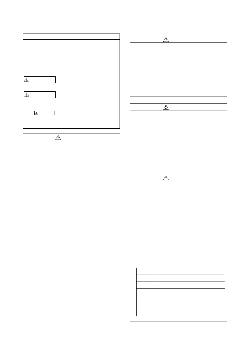
In this Installation Guideline, the safet y instruction levels
are classified into "WARNING" and "CAUTION".
WARNING
CAUTION
CAUTION
The level may even lead to a serious
consequence according to conditions. Both instruction
levels must be followe d because these are im portant to
personal safety.
1. Electric Shoc k Prevention
Incorrect handling may cause
hazardous conditions, resulting in
death or severe injur y.
Incorrect handling may cause
hazardous conditions, resulting in
medium or slig ht injur y, or may cau se
only material damage.
WARNING
z While power is ON or when the inverter is running, do not
open the front cover. Otherwise you may g et an electric
shock.
z Do not run the inverter with the front cover o r wiring cover
removed. Otherwise you may acces s the exposed hi ghvoltage terminals or the charging part of the circuitry and
get an electric shock.
z Even if power is OFF, do not remove the front cover
except for wiring or periodic in spection. You may
accidentally touch the charged inverter circuits and get an
electric shock.
z Before wiring or inspection, power must be switched OFF.
To confirm that, LED indication of the operation panel
must be checked. (It m ust be OFF.) Any person who is
involved in wiring o r inspection shall wait for at least 10
minutes after the po wer supply has been switched OFF
and check that there are n o residual voltage using a teste r
or the like. The capacitor is charged wit h high voltage for
some time after power OFF, and it is dangerous.
z This inverter must be earthed (grounded). Earthing
(grounding) must conform to the requirements of national
and local safety r egulations and elect rical code (NEC
section 250, IEC 536 class 1 and other applicable
standards). A neutral-point earthed (grounded) power
supply for 400V class inverter in compliance with EN
standard must be used.
z Any person who is involved in wiring or inspection of this
equipment shall be fu lly competent to do the work.
z The inverter must be installed before wiring. Otherwise
you may get an electric shock or be injured.
z Setting dial and key operations must be performed with
dry hands to prevent an electric shock. Ot herwise you
may get an electric s hock.
z Do not subject the cables to scr atches, excessive st ress,
heavy loads or pinching. Otherwise you may get an
electric shock.
z Do not change the cooling fan while power is ON. It is
dangerous to change the cooling fan while power is ON.
z Do not touch the printed circuit board or handle the
cables with wet hands. Otherwise you may get an electric
shock.
z When measuring the main c ircuit capacitor capacity, the
DC voltage is applied to the motor for 1s a t powering OFF.
Never touch the motor terminal, etc. right after powe ring
OFF to prevent an el ectric shock.
2. Fire Prevention
CAUTION
z Inverter must be installed on a nonflammable wall without
holes (so that nobody touches the inverter heatsink on the
rear side, etc.). M ounting it to or near flammable mat erial
can cause a fire.
z If the inverter has become faulty, the inverter power mu st
be switched OFF. A continuous flow of large current could
cause a fire.
z
When using a brake resistor, a sequence that will turn OFF
power when a fault s ignal is output mu st be configured.
Otherwise the brake resistor may overheat due to damage
of the brake transistor and possibly cause a fire.
z Do not connect a resistor directly to the DC terminals P/ +
and N/-. Doing so could cause a fire.
3.Injury Prevention
CAUTION
z The voltage applied to each terminal must be th e ones
specified in the Instruction Manual. Otherwise burst,
damage, etc. may occur.
z The cables must be connected t o the correct termina ls.
Otherwise burst, damage, etc. may occur.
z Polarity must be correct. Other wise burst, damage, etc.
may occur.
z While power is ON or for some time after power-OFF, do
not touch the in verter since th e inverter will be extremely
hot. Doing so can cause burns.
4. Additional Instructions
Also the following points must be noted to prevent an
accidental failure, injury, electric shoc k, etc.
(1) Transportation and mounting
CAUTION
z The product must be transported in correct method that
corresponds to the weight. Failure to do so may lead to
injuries.
z Do not stack the boxes containing inverters high er than
the number recommended.
z The product must be installed to the position where
withstands the weight of the product according to the
information in the In struction Manual .
z Do not install or operate the inverter if it is damaged or
has parts missing.
z When carrying the inverter, do not hold it by the front
cover or setting dia l; it may fall off or fail .
z Do not stand or rest heavy objects on the product.
z The inverter mounting orientation must be correct.
z Foreign conductive objects must be prevented from
entering the inverter. That includes screws and metal
fragments or other flammable substance such as oil.
z As the inverter is a precision instrument, do not drop or
subject it to impact.
z The inverter must be used under the following
environment: Oth erwise the inverter may be damaged.
Surrounding air
temperature
Ambient
humidity
Storage
temperature
Atmosphere
Environment
Altitude/
vibration
*1 Temperature applicable for a short time, e.g. in transit.
-10°C to +50°C (14°F to 122°F) (non-freezing)
90%RH or less (non-condensing)
-20°C to +65°C *1
Indoors (free from corrosive ga s, flammable
gas, oil mist, dust and dirt)
Maximum 1000m (3280.80feet) above sea level
for standard operation. After that derate by 3%
for every extra 500m (1640.40feet) up to 2500m
(8202feet) (91%) .
2
or less at 10 to 55Hz (directions of X, Y,
5.9m/s
Z axes)
(-4°F to 149°F)
A-1
(2) Wiring
G
CAUTION
z Do not install a power factor cor rection capacitor or surge
suppressor/capacitor type filter on the inverter output
side. These devices on the inverter output side may be
overheated or burn out.
z The connection orientation of the output cables U, V, W to
the motor affects th e rotation direction of the motor.
(3) Trial run
CAUTION
z Before starting operation, each parameter must be
confirmed and adjusted. A fa ilure to do so may cause
some machines to ma ke unexpected motions.
(4) Usage
WARNIN
z Any person must stay away from t he equipment when the
retry function is set as it will restart suddenly after trip.
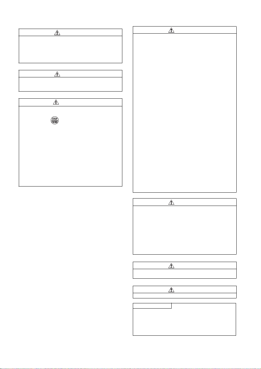
z Since pressing key may not stop output dependi ng
on the function s etting status, separate circuit and switch
that make an emerg ency stop (power OFF, mechanical
brake operation for em ergency stop, etc.) must b e
provided.
z OFF status of the start signal must be confirmed before
resetting the inverter fa ult. Resetting inverter alar m with
the start signal ON restarts the motor suddenly.
z The inverter must be used for three-phase induction
motors. Connection of any other electrical equipment to
the inverter output may damage the equipment.
z Do not modify the equipment.
z Do not perform parts removal which is not instructed in
this manual. Doing so may lead to fault or damage of the
product.
z The electronic thermal relay function does not guarantee
protection of the motor from overheating. It is
recommended to in stall both an external therm al and PTC
thermistor for over heat protection.
z Do not use a magnetic contactor on the inverter input for
frequent starting/stopping of the inverter. Otherwise the
life of the invert er decreases.
z The effect of electromag netic interference must be
reduced by using an EMC filter or by other means.
Otherwise nearby electronic equipment may be affected.
z Appropriate measures must be taken to suppress
harmonics. Otherwise power supply harmonics from the
inverter may heat/d amage the power fac tor correction
capacitor and generator.
z When driving a 400V class motor by the inver ter, the
motor must be an insulation-enhanced motor or measures
must be taken to suppress surge voltage. Surge voltage
attributable to the wiring constants may occur at the
motor terminals, deteriorating the insulation of the motor.
z When parameter clear or all param eter clear is perf ormed,
the required paramet ers must be set ag ain before starting
operations becaus e all parameters return t o the initial
value.
z The inverter can be easily set for high-speed operation.
Before changing its setting, the performances of the
motor and machine must be fully examined.
z Stop status cannot be hold by the inverter's brake
function. In addition to the inverter's brake function, a
holding device must be installed to ensure safety.
z Before running an inverter which had been stored for a
long period, inspection and test operation must be
performed.
z Static electricity in your body must be discharged before
you touch the product. Otherwise the product may be
damaged.
z If you are installing the invert er to drive a three-pha se
device while you are contracted for lighting and power
service, consult your electric power supplier.
(5) Emergency stop
CAUTION
CAUTION
z A safety backup such as an emerg ency brake must be
provided to prevent hazardous condition to the machine
and equipment in c ase of inverter failure.
z When the breaker on the inverter input side trips, the
wiring must be checked for fault (short circuit), and
internal parts of the inverter for a damage, etc. Th e cause
of the trip must be i dentified and remo ved before turning
ON the power of t he breaker.
z When any protective func tion is activated, ap propriate
corrective action must be taken, and the inverter must be
reset before resuming operation.
(6) Maintenance, inspection and parts replacement
CAUTION
z Do not carry out a megger (insulation resistance) test on
the control circuit of the inverter. It will cause a fa ilure.
(7) Disposal
CAUTION
z The inverter must be treate d as industrial waste.
General instruction
Many of the diagrams and drawings in this Installation
Guideline show the in verter without a co ver or partially
open for explanation. Never operate the inverter in t his
manner. The cover must be alwa ys reinstalled and the
instruction in this Installation Guideline m ust be followed
when operating the inverter.
A-2
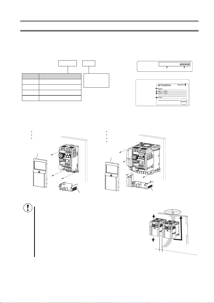
1 PRODUCT CHECKING AND PARTS IDENTIFICATION
Unpack the inverter and check the capacity plate on the front cover and the rating plate on the inverter side face to ensure that
the product agrees with your order and the inverter is intact.
Inverter model
---
FR D740 036
Symbol Voltage class
D720
D740
D720S
D710W
z Installation of the inverter
Three-phase 200V class
Three-phase 400V class
Single-phase 200V class
Single-phase 100V class
Represents
the rated
current
NA
Enclosure surface mounting
Remove the front cover and wiring cover to mount the inverter to the surface.
FR-D720-008 to 042
FR-D720S-008 to 042
FR-D710W-008 to 025
FR-D720-070 or higher
FR-D740-012 or higher
FR-D720S-070, 100
FR-D710W-042
Capacity plate
Rating plate
Rating plate
Inverter model
Input rating
Output rating
Serial number
FR-D740-036-NA
Inverter model
Production year and month
Serial number
DATE:XXXX-XX
FR-D740-036-NA
Front cover
Wiring cover
Front cover
Note
y When encasing multiple inverters, install them in parallel as a
cooling measure.
y When using the inverters at the surrounding air temperature of
40
°C (104°F)
clearance between them (0cm (0 inches) cl earance). When
surrounding air temp erature exceeds 40
between the inverters should be 1cm (0.39inches) or more (5cm
(1.96inches) or more fo r the FR-D720-238 and FR-D740-120 or
higher) .
y Install the in verter vertically.
or less, the inverters can be installed without any
°C (104°F)
, clearances
10cm(3.94inches)
or more
10cm(3.94inches)
or more
Wiring cover
Refer to the clearances
on the left.
Vertical
1
PRODUCT CHECKING AND PARTS IDENTIFICATION
)
z General Precau tion
The bus capacitor discharge time is 10 minutes. Before starting wiring or inspection, switch power OFF, wait for more than 10
minutes, and check for residual voltage between terminal P/+ and N/- with a meter etc., to avoid a hazard of electrical shock.
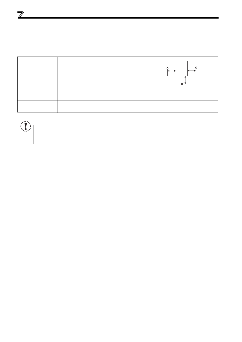
z Environment
Before installation, check that the environment meets the following specifications.
-10°C to +50°C (14°F to 122°F) (non-freezing)
Surrounding air
temperature
5cm
(1.97inches)
Ambient humidity 90% RH or less (non-condensing)
Storage temperature -20°C to +65°C
(
-4°F to 149°F) (Temperature applicable for a short time, e.g. in transit.)
Ambience Indoors (free from corrosive gas, flammable gas, oil mist, dust and dirt)
Maximum 1000m (3280.80feet) above sea level for standard operation. After that derate by 3% for every
Altitude, vibration
extra 500m (1640.40feet) up to 2500m (8202feet) (91%).
5.9m/s2 or less at 10 to 55Hz (directions of X, Y, Z axes)
Note
y Install the inverter on a strong surface securely and vertically with bolts.
y Leave enough clearances and take cooling measures.
y Avoid places where the inverter is subjected to direct sunlight, high temperature and high humidity.
y Install the inverter on a nonflammable wall surface.
Measurement
position
Inverter
Measurement
position
5cm
(1.97inches
5cm
(1.97inches)
2
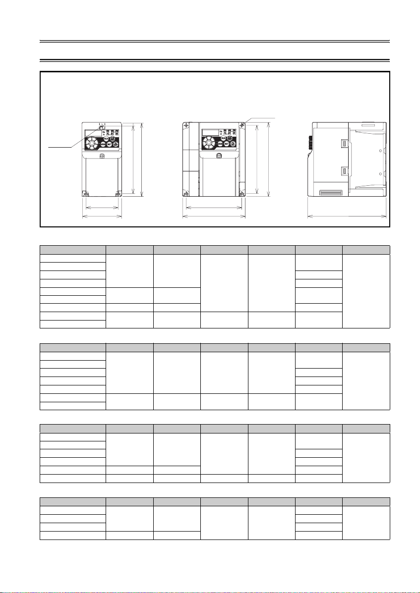
2 OUTLINE DIMENSION DRAWINGS
z FR-D720-008 to 042
z FR-D720S-008 to 042
z FR-D710W-008 to 025
z FR-D720-070 to 318
z FR-D740-012 to 160
z FR-D720S-070, 100
z FR-D710W-04 2
2-φC hole
1-φC hole
H
H1
W1
W
W1
W
H
H1
(Unit:mm(inches))
• Three-phase 200V class
Inverter Model W W1 H H1 D C
FR-D720-008
FR-D720-014
FR-D720-025
FR-D720-042 132.5(5.22)
FR-D720-070
FR-D720-100
FR-D720-165
FR-D720-238
FR-D720-318
68(2.68) 56(2.20)
128(5.04) 118(4.65)
108(4.25) 96(3.78) 135.5(5.34)
170(6.69) 158(6.22) 142.5(5.61)
220(8.66) 208(8.19) 150(5.91) 138(5.43) 155(6.10)
80.5(3.17)
112.5(4.43)
• Three-phase 400V class
Inverter Model W W1 H H1 D C
FR-D740-012
FR-D740-022
FR-D740-036
FR-D740-050
FR-D740-080
FR-D740-120
FR-D740-160
108(4.25) 96(3.78) 128(5.04) 118(4.65)
220(8.66) 208(8.19) 150(5.91) 138(5.43) 155(6.10)
129.5(5.10)
135.5(5.34)
155.5(6.12)
165.5(6.52)
• Single-phase 20 0V class
Inverter Model W W1 H H1 D C
FR-D720S-008
FR-D720S-014
FR-D720S-025
FR-D720S-042 162.5(6.40)
FR-D720S-070 108(4.25) 96(3.78) 155.5(6.12)
FR-D720S-100 140(5.51) 128(5.04) 150(5.91) 138(5.43) 145(5.71)
68(2.68) 56(2.20)
128(5.04) 118(4.65)
80.5(3.17)
142.5(5.61)
• Single-phase 10 0V class
Inverter Model W W1 H H1 D C
FR-D710W-008
FR-D710W-014
FR-D710W-025
FR-D710W-042
68(2.68) 56(2.20)
128(5.04) 118(4.65)
108(4.25) 96(3.78) 149.5(5.89)
80.5(3.17)
110.5(4.35)
142.5(5.61)
D
5(0.20)
5(0.20)
5(0.20)
5(0.20)
3
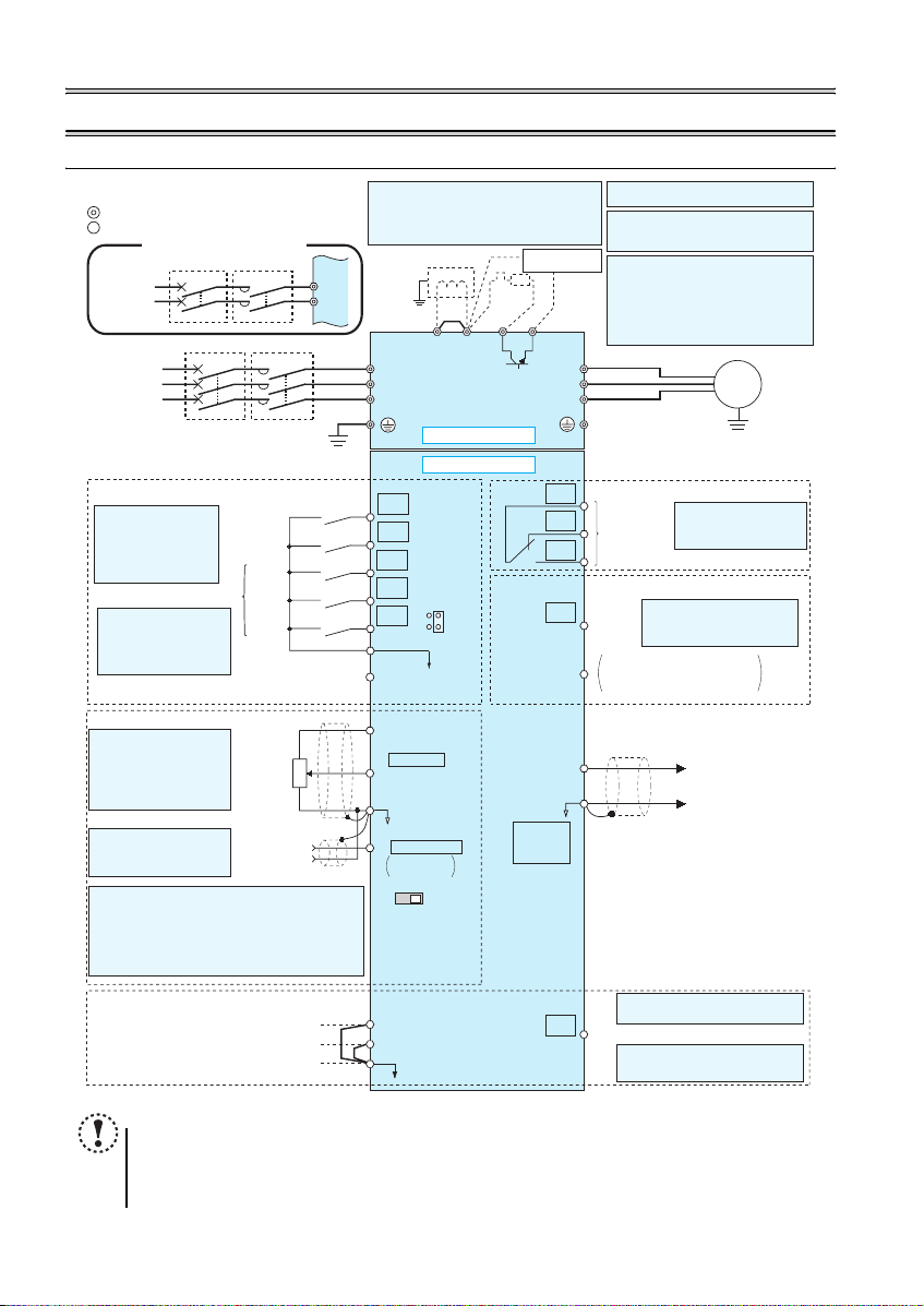
WIRING
3WIRING
3.1 Terminal connection diagram
*
R/L1
S/L2
1. DC reactor (FR-HEL)
When connecting a DC reactor, remove the
jumper across P1-P/+.
Single-phase 100V power input model is not
compatible with DC reactor.
Earth
(Ground)
Jumper
P1 P/+
*6
R/L1
S/L2
T/L3
Sink logic
Main circuit terminal
Control circuit terminal
Single-phase power input
Single-phase
AC power
supply
Three-phase
AC power
supply
MCCB MC
MCCB MC
*6 Terminal P1 is not available for single-
phase 100V power input model.
*7 A brake transistor is not built-in to the
FR-D720-008 and 014, FR-D720S-008
Brake unit
*1
(Option)
R
*8
PR
N/-
*7
and 014, FR-D710W-008 and 014.
*8 Brake resistor (FR-ABR, MRS type, MYS
type)
Install a thermal relay to prevent an
overheat and burnout of the brake resistor.
(The brake resistor can not be connected
to the FR-D720-008 and 014, FR-D720S008 and 014, FR-D710W-008 and 014.)
U
V
W
Motor
IM
Earth
(Ground)
Control input signals (No voltage input allowed)
The function of these
terminals can be changed
to the reset signal, etc.
with the input terminal
assignment (Pr.178 to
Pr.182).
Multi-speed selection
*2 When using terminals PC-
SD as a 24VDC power
supply, take care not to
short across terminals
PC-SD.
Frequency setting signals (Analog)
*3 Terminal input specifications
can be changed by analog
input specifications
switchover (Pr. 73).
Terminal 10 and terminal 2
are used as PTC input
terminal (Pr. 561).
*4 It is recommended to use
2W1kΩ when the
frequency setting signal is
changed frequently.
*5 Terminal input specifications can be changed by analog
input specifications switchover (Pr. 267). Set the
voltage/current input switch in the "V" position to select
voltage input (0 to 5V/0 to10V) and "I" (initial value) to
select current input (4 to 20mA).To use terminal 4 (initial
setting is current input), set "4" in any of Pr.178 to Pr.182
(input terminal function selection) to assign the function, and
turn ON AU signal.
Safety stop signal
Forward
rotation start
Reverse
rotation start
High
speed
Middle
speed
Low
speed
Contact input common
(Common for external power supply transistor)
24VDC power supply
3
Frequency
setting
potentiometer
1/2W1kΩ
*4
1
Terminal 4
input
(Current
input)
2
(+)
(-)
Shorting
Safety stop input (Channel 1)
Safety stop input (Channel 2)
Safety stop input common
STF
STR
PC
10(+5V)
2 0 to 5VDC
5(Analog common)
Voltage/current
input switch
S1
wire
S2
SC
Main circuit
Control circuit
RH
RM
RL
SD
SOURCE
*2
(0 to 10VDC)
4 4 to 20mADC
0 to 5VDC
0 to 10VDC
VI
Earth (Ground)
C
B
A
Relay output
(Fault output)
Relay output
Terminal functions vary
by Pr. 192 A,B,C terminal
function selection
Open collector output
SINK
*3
RUN
SE
AM
5
PU
connector
*5
Terminal functions vary by
Pr. 190 RUN terminal function
Running
selection
Open collector output common
Sink/source common
(+)
Analog signal output
(-)
(0 to 10VDC)
*5
Terminal functions vary by Pr. 197
SO
SO terminal function selection
Safety monitor output *9
*9 Common terminal of terminal SO is
terminal SC. (Connected to
terminal SD inside of the inverter.)
NOTE
y
To prevent a malfunction caused by noise, separate the signal cables more than 10cm (3.93inc h) from the power cables.
Also separate the main circuit wire of the input side and the output side.
y After wiring, wire offcuts must not be le ft in the inverter.
Wire offcuts can cause an alarm, failure or m alfunction. Always keep the inverter clean. W hen drilling mountin g holes
in an enclosure etc., take c are not to allow chips and oth er foreign matter to en ter the inverter.
y The output of the single-phase power input model is three-phase 200V.
4
WIRING
r
r
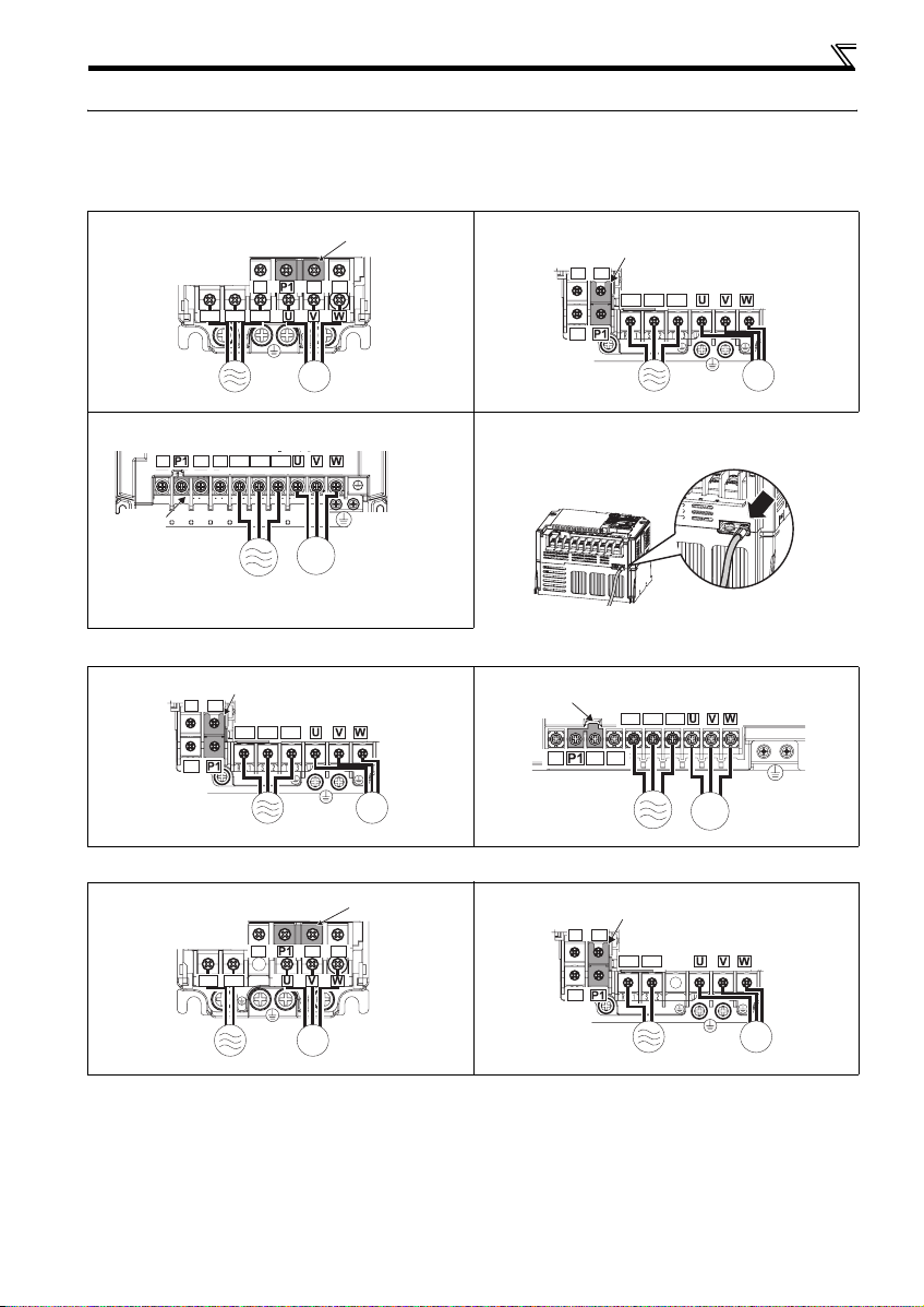
3.2 Main circuit terminal specifications
3.2.1 Terminal arrangement of the main circuit terminal, power supply and the motor wiring
z Three-phase 200V class
FR-D720-008 to 042 FR-D720-070 to 165
Screw size (M3.5)
N/-
R/L1 S/L2 T/L3
Screw size
(M3.5)
FR-D720-238, 318 * For wiring to earth (g round) terminals of FR-D 720-238 and 318,
Screw size (M5)
N/-
P/+ PR
R/L1 S/L2 T/L3
P/+ PR
IM
MotorPower supply
Jumpe
Jumper
N/-
P/+
Screw size (M4)
R/L1 S/L2 T/L3
PR
Screw size
IM
(M4)
Power supply
use earthing cable wiring s pace (marked with an arrow) to route the
wires.
Motor
Jumper
Screw size (M5)
IM
Power supply Motor
z Three-phase 400V class
FR-D740-012 to 080 FR-D740-120, 160
z Single-phase 200V class
FR-D720S-012 to 080 FR-D720S-120, 160
Jumper
N/-
P/+
Screw size (M4)
R/L1 S/L2 T/L3
PR
Screw size (M3.5)
N/-
R/L1 S/L2
Screw size
(M3.5)
Screw size
(M4)
P/+ PR
IM
MotorPower supply
Jumper
N/-
IM
MotorPower supply
Jumpe
Screw size (M4)
R/L1 S/L2 T/L3
P/+
PR
Screw size
(M4)
IM
MotorPower supply
Jumper
N/-
P/+
Screw size (M4)
R/L1 S/L2
PR
Screw size
(M4)
IM
MotorPower supply
5
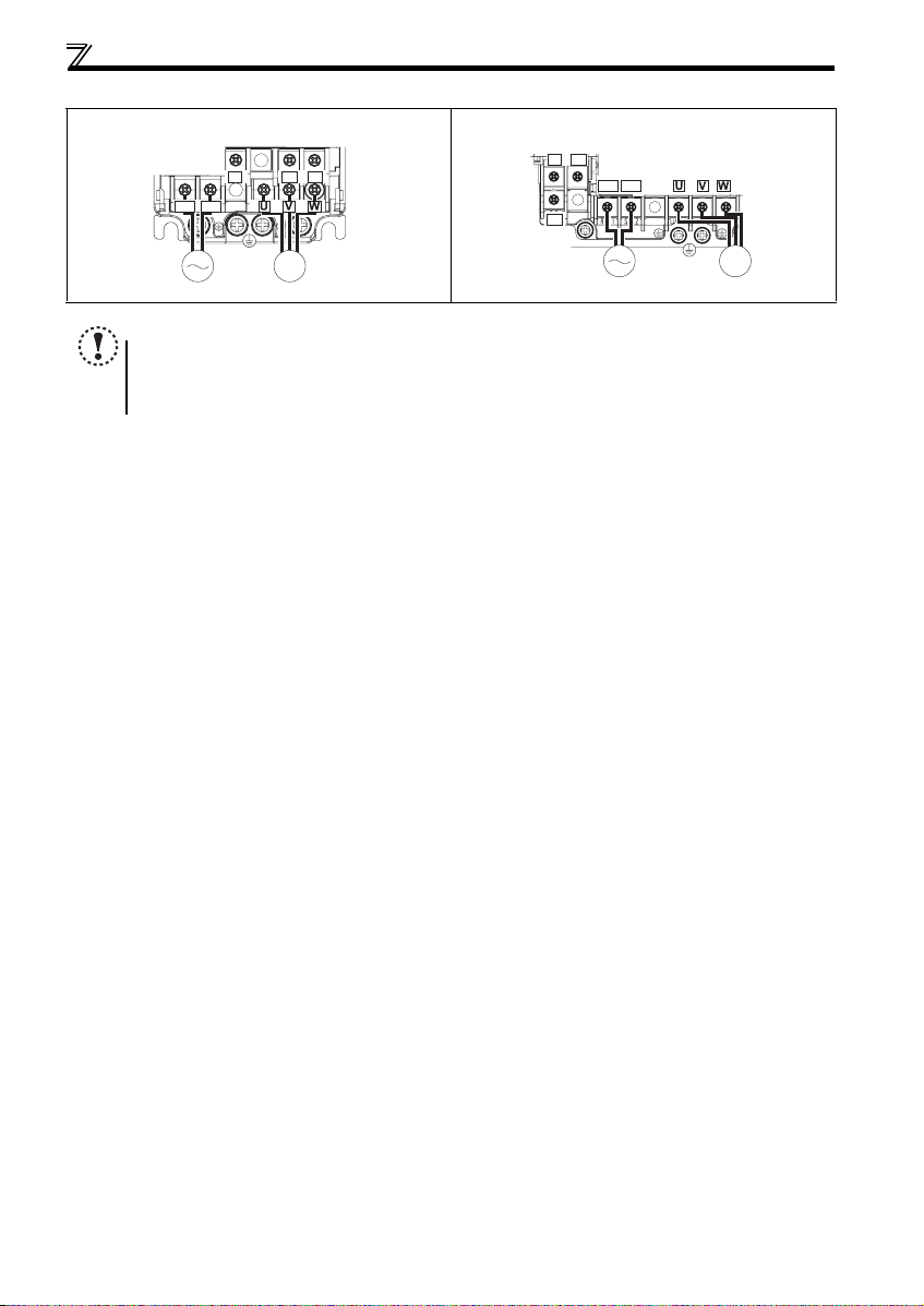
WIRING
z Single-phase 100V class
FR-D710W-008 to 025 FR-D710W-042
Screw size (M3.5)
N/-
P/+
Screw size (M4)
R/L1 S/L2
Power supply
Screw size
(M4)
R/L1 S/L2
N/-
Screw size
(M3.5)
P/+ PR
PR
IM
MotorPower supply
NOTE
y Make sure the power cables are connected to the R/L1, S/L2, T/L3. (Phase need not be matched.) Never connect the
power cable to the U, V, W of the inverter. Doing so w ill damage the inverter.
y Connect t he motor to U, V, W. Turning ON the forward rotation switch (signal) at this time rotates the motor
counterclockwise when viewed from the load shaft.
IM
Motor
6
 Loading...