

S-PM GEARED MOTOR DRIVE UNIT
FR-D700-G
INSTRUCTION MANUAL (BASIC)
FR-D720-0.2K to 3.7K-G
1
Thank you for choosing this Mitsubishi S-PM geared motor drive unit.
This Instruction Manual (Basic) provides handling informati on and precau tions for use of the equipment.
Please forward this Inst ruction Manual (Basic) to the end user.
CONTENTS
OUTLINE ...................................................................................1
1
INSTALLATION AND WIRING ...................................................5
2
PRECAUTIONS FOR USE OF THE DRIVE UNIT ......................16
3
FAILSAFE OF THE SYSTEM WHICH USES THE DRIVE UNIT .18
4
DRIVE THE MOTOR.................................................................19
5
PARAMETERS .........................................................................27
6
TROUBLESHOOTING ..............................................................31
7
PRECAUTIONS FOR MAINTENANCE AND INSPECTION ........36
8
SPECIFICATIONS....................................................................38
9
To obtain the Instruction Manual (Applied)
Contact where you purchased the drive unit, your Mitsubishi sales
representative, or the nearest Mitsubishi FA Center for the following
manuals:
y Instruction Manual (Applied) [IB(NA)-0600478ENG]
These manuals are required if you are going to utilize functions and
performance.
The PDF version of this manual is also available for download at the
"Mitsubishi Factory Automation Website", which is an information service
offered on the Internet.
(URL: www.MitsubishiElectric.co.jp/fa/)
700
2
3
4
5
6
7
8
9
This Instruction Manual (Basic) provides handling information and precautions for use of the equipment.
Please forward this Instruction Manual (Basic) to the end user.
This section is specifically about safety matters
Do not attempt to install, operat e, maintain or inspect the drive
unit until you have read through the Instruction Manual (Basic)
and appended documents carefully and can use the equipment
correctly. Do not use this product until you have a full
knowledge of the equi pment, safety informat ion and
instructions.
In this Instruction Manua l (Basic), the safety instructio n levels
are classified into "WARNING" an d "CAUTION".
WARNING
CAUTION
CAUTION
The level may even lead to a serious
consequence according to conditions. Both instruction levels
must be followed because these are important to personal
safety.
Incorrect handling may caus e
hazardous conditions, resulting in death
or severe injury.
Incorrect handling may caus e
hazardous conditions, resulting in
medium or slight injury, or may cause
only material damage.
1. Electric Shock Prevention
WARNING
While power is ON or when the drive unit is running, do not
z
open the front cover. Otherwise you may get an electric shock.
z Do not run the drive unit with the front cover or wiring cover
removed. Otherwise you may access the exposed highvoltage terminals or the charging part of the circuitry and
get an electric shock.
z Even if power is OFF, do not remove the front cover except
for wiring or periodic inspection. You may accidentally
touch the charged drive unit circuits and get an electric
shock.
z Before wiring or inspection, power must be switched OFF.
To confirm that, LED indication of the operation panel must
be checked. (It must be OFF.) Any person who is involve d in
wiring or inspection shall wait for at least 10 minutes after
the power supply has been switched OFF and check that
there are no residual voltage using a tester or the like. The
capacitor is charged with h igh voltage for some time a fter
power OFF, and it is dangerous.
z This drive unit must be earthed (grounded). Earthing
(grounding) must conform to the requirements of national
and local safety regulatio ns and electrical code (NEC
section 250, IEC 536 cl ass 1 and other appl icable standards).
z Any person who is involved in wiring or inspection of this
equipment shall be f ully competent to do the work.
z The drive unit must be installed before wiring. Otherwise
you may get an elect ric shock or be injured .
z Setting dial and key operations must be performed with dry
hands to prevent an ele ctric shock. Otherwise yo u may get
an electric shock.
Do not subject the cables to scratches, excessive stress, heavy
z
loads or pinching. Otherwise you may get an electric shock.
z Do not change the cooling fan while power is ON. It is
dangerous to change the cooling fan while power is ON.
z Do not touch the printed circuit bo ard or handle t he cables
with wet hands. Otherwise you may get an electric shock.
z When measuring the main ci rcuit capacitor capacity, the DC
voltage is applied to the motor for 1s at p owering OFF. Never
touch the motor terminal, etc. right after powering OFF to
prevent an electric shock.
PM motor is a synchronous motor with embedded
z A
magnets. High-voltage is generated at motor terminals while
the motor is running even after the drive unit power is turned
OFF. Before wiring or inspection, the motor must be
confirmed to be stopped. For applications where the motor is
driven by the load, the low-voltage manual contactor, which
is installed at the drive unit's output side, must be opened
before wiring or inspection. Otherwise you may get an
electric shock.
2. Fire Prevention
z Drive unit must be installed on a nonflammable wall without
holes (so that nobody touches the drive unit heatsink on the
rear side, etc.). Mounting it to or near flammable material
can cause a fire.
z If the drive unit has become faulty, the drive unit power must
be switched OFF. A continuous flow of large current could
cause a fire.
z
When using a brake resistor, a sequence that will turn OFF
power when a fault signal is output must be configured.
Otherwise the brake resistor may overheat due to damage of
the brake transistor and possibly cause a fire.
z Do not connect a resistor directly to the DC terminals P/+
and N/-. Doing so could cause a fire.
CAUTION
3.Injury Prevention
z The voltage applied to each terminal must be the ones
specified in the Instruction Manual. Otherwise burst,
damage, etc. may occu r.
z The cables must be connected to the co rrect terminals.
Otherwise burst, damage, etc. may occur.
z Polarity must be correct. Otherwise burst, damage, etc. may
occur.
z While power is ON or for some time after power-OFF, do not
touch the drive un it since the drive un it will be extremel y
hot. Doing so can cause burns.
CAUTION
4. Additional Instructio ns
Also the following points must be noted to prevent an a ccidental
failure, injury, electric shock, etc.
(1) Transportation and Mounting
CAUTION
z The product must be transported in correct method that
corresponds to the weight. Failure to do so may lead to
injuries.
z Do not stack the boxes containing drive units higher than
the number recommended.
z The product must be installed to the position where
withstands the weight of the product according to the
information in the Instruction Manual.
z Do not install or operate the drive unit if it is damaged or has
parts missing.
z When carrying the drive unit, do not hold it by the front
cover or setting dial; it may fall off or fail.
z Do not stand or rest heavy objects on the product.
z The drive unit mounting orientation must be correct.
z Foreign conductive objects must be prevented from
entering the drive unit. That includes screws and metal
fragments or other flammable substance such as oil.
z As the drive unit is a precision instrument, do not drop or
subject i t to impac t.
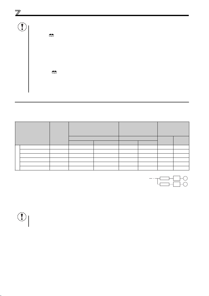
z The drive unit must be used under the following
environment: Otherwi se the drive unit may be damaged.
Surrounding
air
temperature
Ambient
humidity
Storage
temperature
Atmosphere
Environment
Altitude/
vibration
∗ Temperature applicable for a sho rt time, e.g. in transit.
-10°C to +50°C (non-freezing)
90%RH or less (non-condensing)
-20°C to +65°C ∗
Indoors (free from corrosive gas, flammable gas,
oil mist, dust and di rt)
Maximum 1,000m above sea level.
2
or less at 10 to 55Hz (directions of X, Y, Z
5.9m/s
axes)
A-1
(2) Wiring
z Do not install a power factor cor rection capacitor or surg e
suppressor/capacitor type filter on the drive unit output
side. These devices on the drive unit output side may be
overheated or burn out.
z The connection orientation of the output cables U, V, W to
the motor affects the rotation direction of the motor.
z PM motor terminals (U, V, W) hold high-voltage while the PM
motor is running even after the power is turned OFF. Before
wiring, the PM motor must be confirmed to be stopped.
Otherwise you may g et an electric shock.
z Never connect a PM motor to the commercial power supply.
Applying the commercial power supply to input terminals (U,
V, W) of a PM motor will burn the PM motor. The PM motor
must be connected with the o utput terminals (U, V, W) of the
drive unit.
CAUTION
(3) Trial run
z Before starting operation, each parameter must be
confirmed and adjust ed. A failure to do so may ca use some
machines to make unexpected motions .
CAUTION
(4) Usage
WARNING
z A PM motor and the drive unit m ust be used in the specified
capacity combination.
z Do not use multiple PM motors with one drive unit.
z Any person must stay away from the equipment when the
retry function is set as it will restart suddenly after trip.
z
Since pressing key may not stop output depending on
the function setting status, separate circuit and switch that
make an eme rgency stop ( power OFF, mechanica l brake
operation for emergency stop, etc.) must be provided.
z OFF status of the start signal must be confirmed before
resetting the drive unit fault. Resetting drive unit alarm with
the start signal ON restarts the motor suddenly.
z Do not use a PM motor in an applicati on where a motor is
driven by its load an d runs at a speed higher than the
maximum motor speed.
z Do not use a synchronized, induction, or induced-
synchronized motor, that is not a dedicated PM motor.
z Do not use the drive unit for a load other than the dedicated
PM motor.
Connection of any other electrical equipment to the drive
unit output may damage the equipment.
z Do not modify the equipment.
z
Do not perform parts removal which is not instructed in this
manual. Doi ng so may lea d to fault o r damage of the product .
z The electronic thermal relay function does not guarantee
protection of the motor from overheating. It is recommended
to install an external thermal for overheat protection.
z Do not use a magnetic contactor on the drive unit input for
frequent starting/stopping of the drive unit. Otherwise, the
life of the drive unit dec reases.
z The effect of electromagnetic interference must be reduced
by using an EMC filter or by other means. Otherwise nearby
electronic equipment may be affected.
z Appropriate measures must be taken to s uppress
harmonics. Otherwise power supply harmonics from the
drive unit may he at/damage the powe r factor correct ion
capacitor and generator.
When parameter clear or all parameter clear is performed, the
z
required parameters must be set again before starting
operations becaus e all param eters re turn to th e initia l value.
z The drive unit can be easily set for high- speed operation.
Before changing its setting, the performances of the motor
and machine must be fully examined.
z Stop status cannot be hold by the drive unit's brake
function. In addition to the drive unit's brake function, a
holding device must be installed to ensure safety.
z Before running a drive unit which had been stored for a long
period, inspection and test operation must be performed.
z Static electricity in your body must be discharged b efore
you touch the product. Otherwise the product may be
damaged.
z In the system with a PM motor, the drive unit pow er must be
turned ON before closing the contacts of the contactor at the
output side.
z If you are installing the dr ive unit to drive a thr ee-phase
device while you are contracted for lighting and power
service, consult your ele ctric power supplier.
CAUTION
(5) Emergency stop
CAUTION
z A safety backup such as an emergency brake must be
provided to prevent hazardous condition to the machine and
equipment in case of dr ive unit failure.
z When the breaker on the drive unit input side trips, the
wiring must be checked for fault (short circuit), and internal
parts of the drive unit for a damage, etc. The cause of the trip
must be identified and re moved before turn ing ON the power
of the breaker.
z When any protective function is activated, appropriate
corrective action mu st be taken, and the dr ive unit must be
reset before resuming operation.
(6) Maintenance, inspection and parts replacement
CAUTION
z Do not carry out a megger (insulation resistance) test on the
control circuit of the dri ve unit. It will cause a failure.
(7) Disposal
CAUTION
z The drive unit must be treated as industrial waste.
General instruction
Many of the diagrams and drawings in this Instruction Manual
(Basic) show the drive unit without a cover or partially open
for explanation. Never operate the drive unit in this manner.
The cover must be always reinstalled an d the instruction in
this Instruction Manua l (Basic) must be follow ed when
operating the drive unit.
For more details on a dedicated PM motor, refer to the
Instruction Manual of the dedicated PM motor.
A-2
<Abbreviation>
PU...................................................Operation panel and parameter unit (
Drive unit.........................................The FR-D700-G series drive unit for Mitsubishi S-PM geared motor
D700-G.....................................The FR-D700-G series drive unit for Mitsubishi S-PM geared motor
FR-
Pr. ...................................................Parameter number (Number assigned to function)
PU operation...................................Operation using the PU (operation panel/FR-PU07)
External operation...........................Operation using the control circuit signals
Combined operation .......................Operation using both the PU (operation panel/FR-PU07) and External operation
PM motor ........................................The S-PM series dedicated magnet (PM) motor
<Trademark>
y Company and product names herein are the trademarks and registered trademarks of their respective owners.
<Mark>
REMARKS :
Additional helpful contents and relations with other functions are stated.
FR-PU07)
NOTE :Contents requiring caution or cases when set functions are not activated are stated.
POINT :Useful contents and points are stated.
<Related document>
Refer to the Instruction Manual (Applied) for further information on the following points.
y Removal and reinstallation of the cover
y Connection of stand-alone option unit
y EMC and leakage currents
y Detailed explanation on parameters
y Troubleshooting
y Check first when you have a trouble
y Inspection items (life diagnosis, cooling fan replacement)
y Measurement of main circuit voltages, currents and powers
Harmonic suppression guideline (when drive units are used in Japan)
All models of general-pu rpose inverters used b y specific consumers a re covered by "The Har monic Suppression Gui deline for Consumers
Who Receive High Voltage or Special High Voltage". (For fur ther details, refer to Chapter 3 of the Instruction Manual (Applied).)
A-3

1 OUTLINE
1.1 Product checking and parts identification
Unpack the drive unit and check the capacity plate on the front cover and the rating plate on the drive unit side face to ensure
that the product agrees with your order and the drive unit is intact.
zDrive unit model
--
FR
D720 1.5
-
G
K
Symbol Voltage class
Three-phase 200V class
D720
Cooling fan
The cooling fan is removable.
( Refer to the Instruction
Manual (Applied))
Operation panel
(Refer to page 2)
Voltage/current input switch
(Refer to page 8)
PU connector
(Refer to page 8)
Front cover
Refer to the Instru ction
Manual (Applied) for
installation/removal.
Capacity plate
Drive unit model
Represents the drive
unit capacity [kW]
Serial number
Represents the S-PM
geared motor drive
Rating plate
Drive unit model
Input rating
Output rating
Serial number
Control logic switchover jumper
connector
The jumper connector is in the sink
logic (SINK) when shipped from the
factory. Move the jumper connector
to change to the source logic
(SOURCE). Always fit the jumper
connector to the either position.
( Refer to the I nstruction Manual
(Applied))
Control circuit terminal block
(Refer to page 9)
Main circuit terminal block
(Refer to p age 9)
Combed shaped wiring cover
Refer to the Instruc tion
Manual (Applied) for installatio n/
removal.
Production year and month
DRIVE UNIT
DATE:XXXX-XX
D720 G
1
• Accessory
· Fan cover fixing screws (M3 × 35mm)
Capacity Quantity
0.2K to 0.75K none
These screws are necessary for compliance with the EU Directive.
1.5K to 3.7K 1
(
Refer to page 41
)
REMARKS
y For how to find the SERIAL number, refer to page 44.
y Caution stickers are enclosed with this instruc tion manual. These cau tion stickers include sti ckers that are used f or the
automatic restart after instantaneous power failure function , which are not required for F R-D700-G.
1
Operation panel
1.2 Operation panel
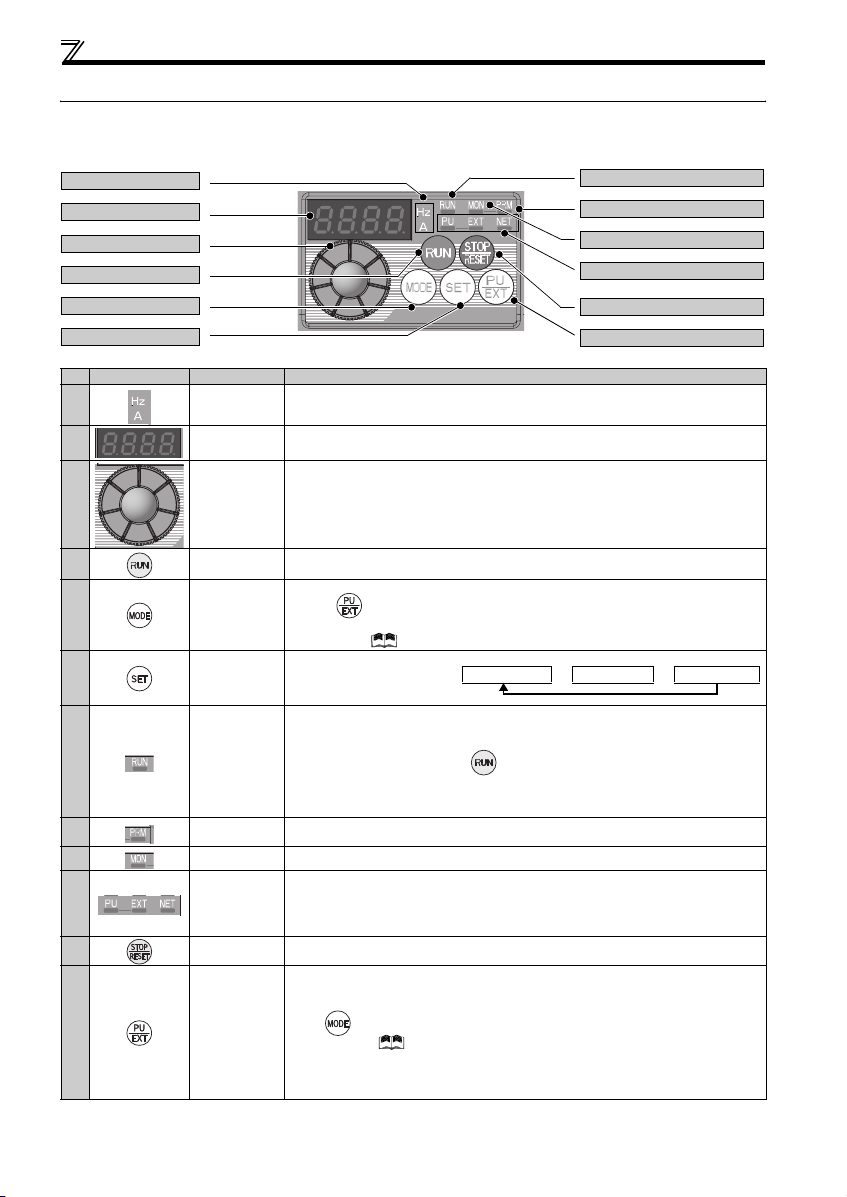
1.2.1 Names and functions of the operation panel
The operation panel cannot be removed from the drive unit.
(a) Unit indicator
(b) Monitor (4-digit LED)
(c) Setting dial
(d) Start command
(e) MODE key
(f) SET key
(g) Operation status in dicator
(h)
Parameter setting mode indicator
(i) Monito r indicat or
(j) Operation mode in dicator
(k) STOP/RESET key
(l) PU/EXT key
No. Component Name Description
(a)
(b)
Unit indicato r
Monitor (4-digit
LED)
(c) Setting dial
(d)
Start command Select the rotation direction in Pr. 40.
(e) MODE key
(f) SET key
(g)
(h)
(i)
(j)
(k)
(l)
Operation status
indicator
Parameter setting
mode indicator
Monitor indicator Lit to indicate the monitor mode.
Operation mode
indicator
STOP/RESET
key
PU/EXT key
Hz: Lit to indicate frequenc y. (Flickers when the set frequency mon itor is displayed.)
A: Lit to indicate curren t.
(Both "Hz" and "A" are lit to indicate a value o ther than frequency or current. )
Shows the speed, parame ter number, etc.
(To monitor the output power, the set speed and other items , set Pr. 52.)
The dial of the Mitsubishi drive unit. The settin g dial is used to change the speed and
parameter settings.
Press to display the following.
y Displays the set speed in the monitor mode
y Present set value is displayed during calibration
y Displays the order in the faults history mode
Used to switch among different setting modes.
Pressing simultaneously change s the operation mode.
Holding this key for 2 se conds locks the operati on. The key lock is invalid when Pr. 161 = "0
(initial setting)." Refer to the Instruction Manual (Applied)
Used to enter a setting.
If pressed during the o peration,
monitored item changes as the
following:
Lit or flickers during dri ve unit operation.
* Lit: When the forward r otation operation is being per formed.
Slow flickering (1.4s c ycle): When the rever se rotation operation is b eing performed.
Fast flickering (0.2s cy cle): When has been pressed or the start comm and has been
y When the speed comman d is less than the starting speed.
y When the MRS signal i s being input.
Lit to indicate the paramet er setting mode.
PU: Lit to indicate the PU operation mode.
EXT: Lit to indicate the External operation mode.( EXT is lit at power-ON in th e initial setting.)
NET: Lit to indicate the Network operation mode .
PU and EXT: Lit to indicate EXT/PU co mbined operation mode 1 and 2
All of these indicators are OFF when the comm and source is not at the operation panel.
Used to stop operation c ommands.
Used to reset a fault when the protective function (fault) is activated.
Used to switch between the PU and External op eration modes.
To use the External operation mode (operatio n using a separately con nected speed setting
potentiometer and start sign al), press this key to lig ht up the EXT indicator.
(Press simultaneously (0.5s), or ch ange the Pr .79 setting to change to th e combined
operation mode. ( Refer to the Instru ction Manual (Applied))
PU: PU operation mode
EXT: External operation mode
Used to cancel the PU stop also.
Rotation speed→Output current→Output voltage
*
given, but the opera tion cannot be made.
2
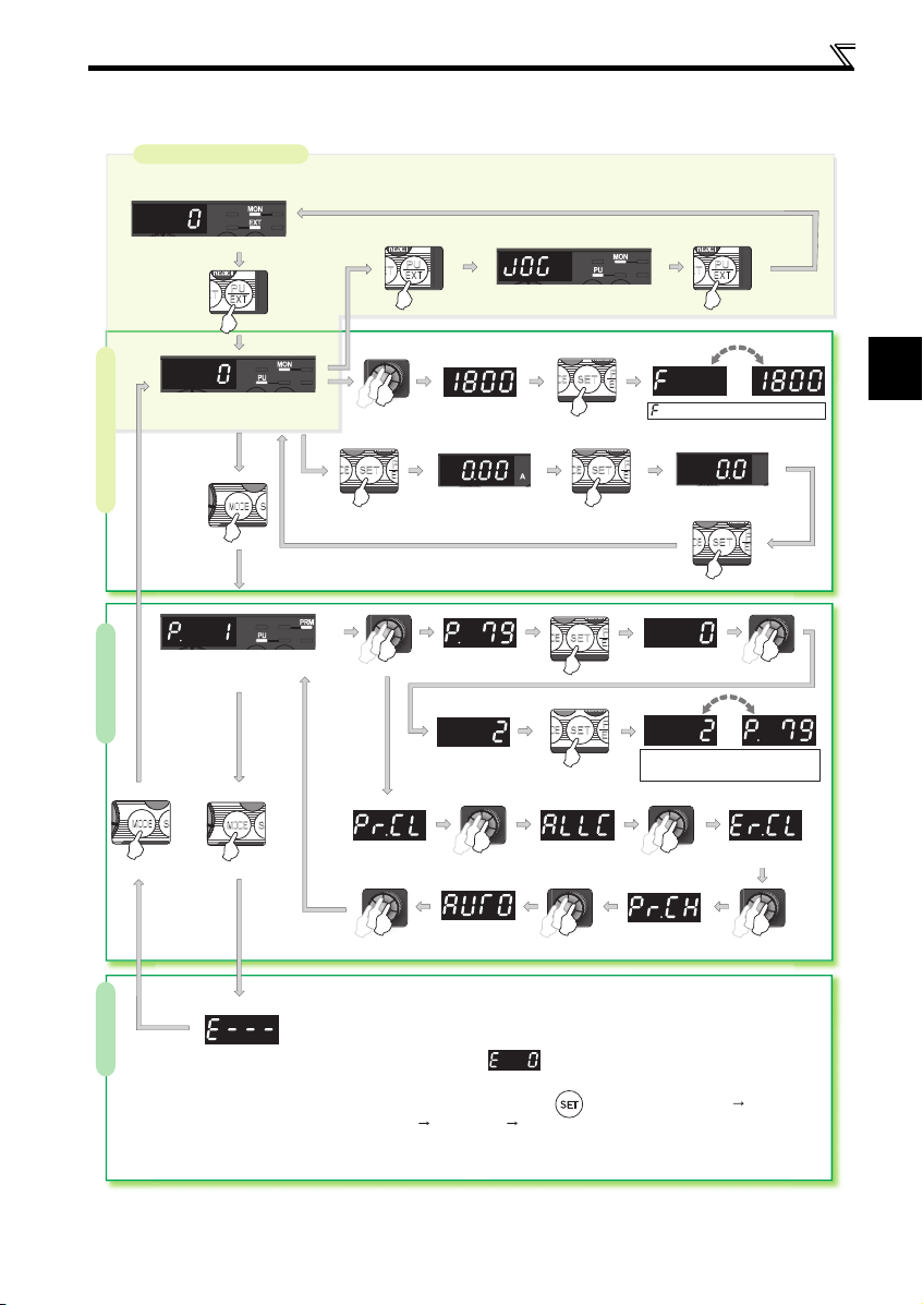
1.2.2 Basic operation (factory setting)
Operation mode switchover
At powering ON (External operation mode)
Operation panel
PU Jog operation mode
PU operation mode
(Rotation speed monitor)
Parameter setting mode
(Refer to page 4)
Parameter settingFaults history Monitor/speed setting
Value change
Output current monitor
Value change
Parameter clear All parameter
Automatic
parameter setting
STOP
clear
(Example)
and the speed flicker alternately.
The speed setting has been
written and completed!!
Output voltage monitor
Display the
present setting
(Example)
Parameter and a setting value
flicker alternately.
Parameter write is completed!!
Faults history clear
Initial value
change list
1
[Operation for displaying faults history]
The past eight faults can be displayed using the setting dial.
(The latest fault is ended by ".".)
When no fault history exists, is displayed.
While a fault is displayed:
The display shifts as follows by pressing : Rotation speed at the fault
Output current Output voltage Energization time.
(After Energization time, it goes back to a fault display.)
Pressing the setting dial shows the fault history number.
(Refer to Chapter 4 of the Instruc tion manual(Applied).)
3
Operation panel
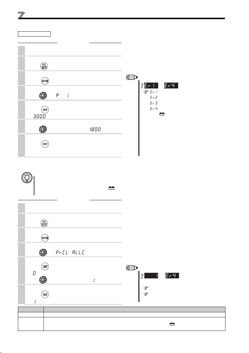
1.2.3 Changing the parameter setting value
Changing example Change the Pr. 1 Maximum setting.
Operation
Screen at power -ON
1.
The monitor display ap pears.
Changing the operation mode
2.
Press to choose the PU operation mode. [PU] indicator is lit.
Parameter setting mode
3.
Press to choose the parameter setting mo de.
Selecting the parameter number
4.
Turn unti l (Pr. 1) appears.
Reading the set value
Press to read the present set value.
5.
" "(3000r/min (initial valu e)) appears.
Changing the setting value
6.
Turn to chang e the set value to " "(1800r/min)
Setting the parameter
Press to set.
7.
The parameter number a nd the setting value flicke r
alternately.
1.2.4 Parameter clear/all parameter clear
POINT
y Set "1" in Pr.CL Parameter clear, ALLC all para meter clear to initialize all parameters. (Parameters are not cleared
when "1" is set in Pr. 77 Parameter write selection.)
y Refer to the extended parameter list of the Instruction Manual (Applied) for parameters cleared with this
operation.
Operation
Screen at power -ON
1.
The monitor display ap pears.
Changing the operation mode
2.
Press to choose the PU operation mode. [PU] indicator is lit.
Parameter setting mode
3.
Press to choose the parameter setting mo de.
Selecting Parameter Clear (All Parameter Clear)
4.
Turn unti l ( ) appears.
Selecting the setting value
Press to read the present set value.
5.
" "(initial value) appears.
Turn to c hange it to the set val ue " ".
Executing Parameter Clear
Press to set.
6.
" " and Pr. CL (ALLC) indications flicker alterna tely.
Setting Description
0 Clear is not executed.
Sets parameters back to t he initial values. (Parame ter clear sets back all parameters except cal ibration par ameters,
1
terminal function selection paramete rs to the initial values.) Refer to the parameter list of the Instruction Manual (Applied)
for availability of parameter clear and all paramete r clear.
REMARKS
to
appears ....... Write disable error
appears ....... Write error during operation
appears ....... Calibration error
(For details, refer to the Instruction Manual (Applied).)
y The number of digits displayed on the operation panel is
appears ....... Mode designation error
four. Only the upper four digits of values can be
displayed and set. If the values to be displayed have five
digits or more including decimal places, the fifth or later
numerals cannot be displayed nor set.
(Example) For Pr. 505
When 60Hz is set, 60.00 is d isplayed.
When 120Hz is s et, 120.0 is displayed and sec ond
decimal place is not displayed nor set.
is displayed...Why?
REMARKS
Why?
and
The drive unit is not in the PU operation mode.
PU connector is used.(Param eter unit (FR-PU07)
is in use.)
are displayed alternately ...
4
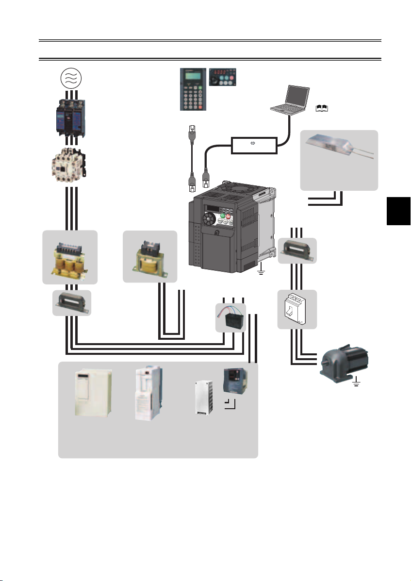
2 INSTALLATION AND WIRING
AC power supply
Use within the permissible power supply
specifications of the drive unit. To ensure
safety, use a moulded case circuit breaker,
earth leakage circuit breaker or magnetic
contactor to switch power ON/OFF.
(Refer to page 38)
Moulded case circuit breaker
(MCCB) or earth leakage circuit
breaker (ELB), fuse
The breaker must be selected carefully
since an in-rush current flows in the
drive unit at power on.
(Refer to page 6)
Magnetic contactor (MC)
Install the magnetic contactor to ensure
safety. Do not use this magnetic contactor
to start and stop the drive unit. Doing so will
cause the drive unit life to be shorten.
(Refer to page 6)
Reactor (FR-HAL, FR-HEL option)
Reactors (option) must be used when
power harmonics measures are taken,
the power factor is to be improved or the
drive unit is installed near a large power
supply system (500kVA or more). The
drive unit may be damaged if you do not
use reactors. Select the reactor according
to the model. Remove the jumpers across
AC reactor (FR-HAL)
* Filterpack (FR-BFP2), which contains DC reactor and noise filter in one package, is also available.
terminals P/+ and P1 to connect the DC reactor.
Install a noise filter (ferrite core)
to reduce the electromagnetic
noise generated from the drive
unit. Effective in the range from
about 1MHz to 10MHz. When
more wires are passed through,
a more effective result can be
obtained. A wire should be
wound four turns or more.
High power factor
converter (FR-HC)
Power supply harmonics
can be greatly suppressed.
Install this as required.
DC reactor (FR-HEL) *
Noise filter (ferrite core) *
(FR-BSF01, FR-BLF)
Power regeneration
common converter
(FR-CV)
Great braking capability
is obtained.
Install this as required.
Parameter unit
(FR-PU07)
P/+
Resistor unit (FR-BR)
Discharging resistor (GZG, GRZG)
The regenerative braking capability
of the drive unit can be exhibited fully.
Install this as required.
Enclosure surface operation
panel (FR-PA07)
By connecting the connection
cable (FR-CB2) to the PU
connector, operation can be
performed from FR-PU07, FRPA0 7.
Drive unit
(FR-D700-G)
P1
Noise filter
(capacitor) *
(FR-BIF)
Reduces the
radio noise.
Brake unit
(FR-BU2)
RS-485 RS-232C
R/L1 S/L2T/L3
PR
P/+
P/+
PR
RS-232C - RS-485 converter is
required when connecting to PC
with RS-232C interface.
( Refer to the
Instruction Manual (Applied))
Converter
Brake resistor (FR-ABR, MRS
type, MYS type)
Braking capability can be impr oved.
(0.4K or higher)
(Refer to page 15)
P/+
PR
Noise filter (ferrite core)
(FR-BSF01, FR-BLF)
V
UW
Earth
(Ground)
N/-
P/+
Devices connected to the output
Do not install a power factor correction capacitor,
surge suppressor or noise filter (capacitor) on the output
side of the drive unit. When installing a moulded case
circuit breaker on the output side of the drive unit,
contact each manufacturer for selection of the
moulded case circuit breaker.
Earth (Ground)
To prevent an electric shock, always earth (ground) the
motor and drive unit. For reduction of induction noise
from the power line of the drive unit, it is recommended
to wire the earth (ground) cable by returning it to the
earth (ground) terminal of the drive unit.
Install a noise filter (ferrite
core) to reduce the
electromagnetic
noise generated from the
drive unit. Effective in the
range from about 1MHz to
10MHz. A wire should be
wound four turns at a
maximum.
Contactor
Example: No-fuse switch
(DSN type)
Install a contactor in an
application where the PM
motor is driven by the load
even at power-OFF of the
drive unit. Do not open or
close the contactor while the
drive unit is running
(outputting).
Motor
Earth
(Ground)
2
5
Peripheral devices
NOTE
y The life of the drive unit is influenced by surrounding air temperature. The surrounding air temperature should be as
low as possible with in the permissible range. This must be noted especially w hen the drive unit i s installed in an
enclosure. ( Refer to Chapter1 of the Instruction Manual(Applied))
y Wrong wiring might lead to damage of the drive unit. The control signal lines must be kept fully away from the main
circuit to protect them f rom noise. (Refer to page 8)
y Do not install a power factor correction capacitor, surge suppressor or EMC filter (capacitor) on the drive unit output
side. This will cause the drive unit to trip or the capacitor and surge suppressor to be damaged. If any of the above
devices are connected, immediate ly remove them.
y Electromagnetic wave interference
The input/output (main circuit) of the drive unit includes high frequency components, which may interfere with the
communication devices (such as AM radios) used near the drive unit. In this case, ins tall the FR-BIF optional EMC
filter (capacitor) (for use in the input side only) or FR-BSF01 or FR-BLF EMC filter (ferrite core) to minimize
interference. ( Refer to Chapter 3 of the Instruction Manual (Applied)).
y Refer to the Instruction Manual of each option and peripheral devices for details of peripheral devices.
y A PM motor cannot be driven by the commercial power supply.
y A PM motor is a m agnet motor. High-voltage is generated at moto r terminals while t he motor is runni ng even after the
drive unit power is turned O FF. Before closing the contactor at the output side, make sure th at the drive unit power is
ON and the motor is stopped.
2.1 Peripheral devices
Check the drive unit model of the drive unit you purchased. Appropriate peripheral devices must be selected according to the
capacity.
Refer to the following lis t and prepare a ppropriate peripheral devices.
Moulded Case Circuit Breaker
(MCCB) ∗1
(ELB) ∗2
Reactor connection Reactor connection
Drive unit Model
Motor
Output
(kW)
or Earth Leakage Circuit Breaker
without with without with
FR-D720-0.2K-G 0.1 5A 5A S-N10 S-N10 0.4K ∗4 0.4K ∗4
FR-D720-0.4K-G 0.2 5A 5A S-N10 S-N10 0.4K ∗4 0.4K ∗4
FR-D720-0.75K-G 0.4 10A 5A S-N10 S-N10 0.4K 0.4K
FR-D720-1.5K-G 0.75 15A 10A S-N10 S-N10 0.75K 0.75K
FR-D720-2.2K-G 1.5 20A 15A S-N10 S- N10 1.5K 1.5K
FR-D720-3.7K-G 2.2 30A 30A S-N20, S-N21 S-N10 2.2K 2.2K
Three-Phase 200V
∗1 ySelect a MCCB according to the power supply capacity.
yInstall one MCCB per drive unit.
∗2 For the use in the United States or Canada, select a UL and cUL certified fuse with Class T fuse equivalent cut-off
speed or faster with the appropriate rating for branch circuit protection. Alternatively, select a UL489 molded case
circuit breaker (MCCB). (Refer to page 44)
∗3 Magnetic contactor is selected based on the AC-1 class. The electrical durability of magnetic contactor is 500,000 times. When the magnetic contactor is
used for emergency stop during motor driving, the electrical durability is 25 times.
If using an MC for emergency stop during motor driving, select an MC regarding the drive unit input side current as JEM1038-AC-3 class rated current.
∗4 The power factor may be slightly lower.
NOTE
y Select a MCCB and a magnetic contactor according to the drive unit model, and cable and reactor according to the motor output.
y When the breaker on the drive unit input side trips, check for the wiring fault (short circuit), damage to internal parts of the drive unit,
etc. Identify the cause of the trip, then remove the cause and power ON the breaker.
Magnetic Contactor (MC)
∗3
Reactor
FR-HAL FR-HEL
Drive
MCCB
unit
Drive
MCCB
unit
IM
IM
6
Installation of the drive units and precautions
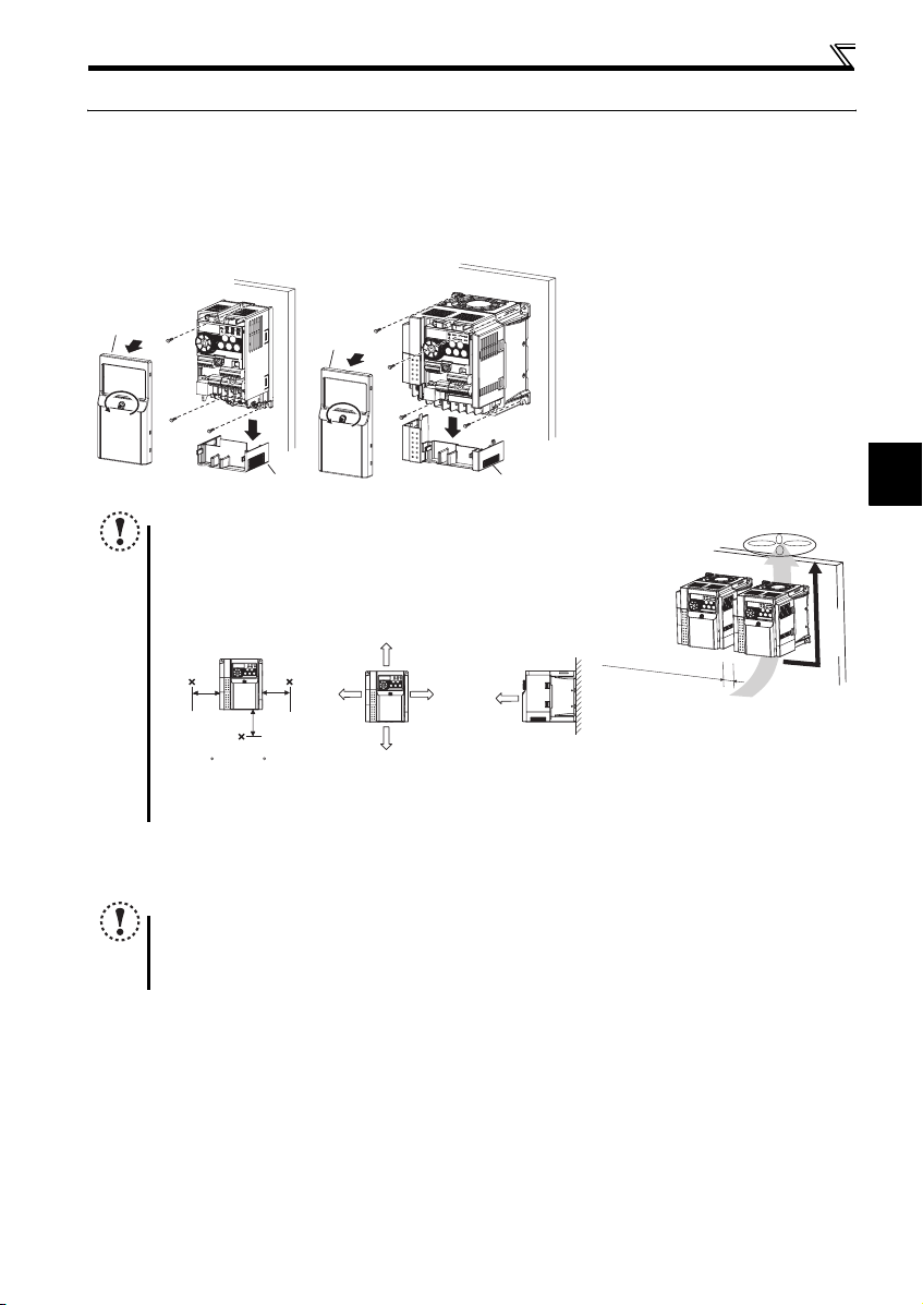
2.2 Installation of the drive units and precautions
(1) Installation of the drive unit
Enclosure surface mounting
Remove the front cover and wiring cover to mount the drive unit to the surface. (Remove the covers in the directions of the
arrows.)
FR-D720-0.2K to 0.75K-G FR-D720-1.5K to 3.7K-G
Front cover
Front cover
Wiring cover Wiring cover
NOTE
y When encasing multiple drive units, install them in paralle l as a cooling
measure.
y Install the drive unit vertically.
y For heat dissipation and maintenance, allow minimum clearance shown
in the figures below from the drive unit to the other devices and to the
inner surface of the enclosure.
Measurement
position
5cm
5cm
1cm or
more
5cm
Measurement
position
-10 C to +50 C
(non-freezing)
* When using the drive units at the surrounding air temperature of 40°C or less, the drive units can be installed without any clearance between
them (0cm clearance).
10cm or more
1cm or
∗
more
10cm or more
1cm or
∗
more
Refer to the clearance
shown on the left.
(2) Environment
Before installation, check that the environment meets the specifications on page 38.
Note
y Install the drive unit on a strong surface securely and vertically with bolts.
y Leave enough clearances and take cooling measures.
y Avoid places where the drive unit is subjected to direct sunlight, high temperature and high humidity.
y Install the drive unit on a nonflammable wall sur face.
2
Vertical
7
Wiring
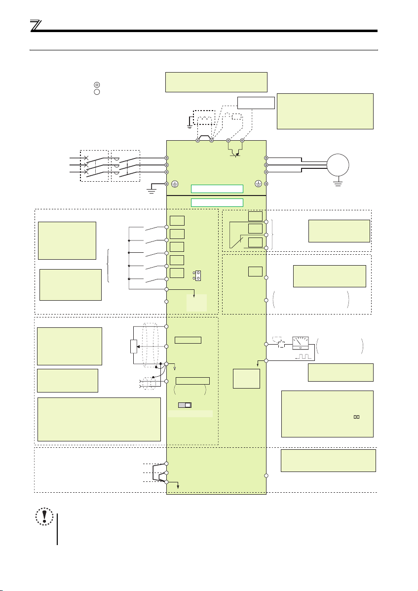
2.3 Wiring
2.3.1 Terminal connection diagram
Sink logic
Main circuit terminal
Control circuit terminal
MCCB MC
Three-phase
AC power
supply
Earth
(Ground)
Control input signals (No voltage input allowed)
The function of these
terminals can be
changed to the reset
signal, etc. with the input
terminal assignment
(Pr. 178 to Pr. 182)
Multi-speed selection
*2 When using terminals PC-
SD as a 24VDC power
supply, take care not to
short across terminals
PC and SD.
(Common for external power supply transistor)
Speed setting signals (Analog)
*3 Terminal input specifications
can be changed by analog
input specifications
switchover (Pr. 73).
Terminal 10 and terminal 2
are used as PTC input
terminal (Pr. 561).
*4 It is recommended to
use 2W1kΩ when the
speed setting signal is
changed frequently.
*5 Terminal input specifications can be changed by analog
input specifications switchover (Pr. 267). Set the
voltage/current input switch in the "V" position to select
voltage input (0 to 5V/0 to10V) and "I" (initial value) to
select current input (4 to 20mA).
To use terminal 4 (initial setting is current input), set "4"
in any of Pr.178 to Pr.182 (input terminal function
selection) to assign the function, and turn ON AU signal.
.
Forward
rotation start
Reverse
rotation start
High
speed
Middle
speed
Low
speed
Contact input common
24VDC power supply
3
Speed
setting
potentiometer
1/2W1kΩ
*4
1
Terminal 4
(+)
input
(-)
(Current
input)
2
For manufacturer *9
*1. DC reactor (FR-HEL)
When connecting a DC reactor, remove the
jumper across P1 and P/+.
Jumper
*1
*6
PR
Earth
(Ground)
P1 P/+
R/L1
S/L2
T/L3
Main circuit
Control circuit
STF
STR
RH
RM
RL
SD
PC
10(+5V)
2 0 to 5VDC
(0 to 10VDC)
5(Analog common)
4 4 to 20mADC
VI
Voltage/current
input switch
S1
S2
SC
SOURCE
*2
0 to 5VDC
0 to 10VDC
SINK
*3
*5
*5
Brake unit
(Option)
R
N/-
RUN
PU
connector
*8
*6 Brake resistor (FR-ABR, MRS type, MYS
type)
Install a thermal relay to prevent an
overheat and burnout of the brake resistor.
(The brake resistor cannot be connected
to the 0.2K.)
U
V
W
C
B
A
Relay output
(Fault output)
Relay output
Open collector output
Terminal functions vary by
Pr. 190 RUN terminal function
Running
selection
Open collector output common
SE
Sink/source common
Calibration resistor
+
-
FM
*7
SD
*8 Operation and parameter setting can be
done from the parameter unit (FRPU07) and the enclosure surface
operation panel (FR-PA07).
(Use the option cable (FR-CB2 ).)
RS-485 communication can be utilized
from a personal computer and other
devices.
*9 The terminals S1, S2, SC, and SO are for
manufacturer setting. Do not remove the
shortening wires across the terminals S1
and SC and the terminals S2 and SC.
For manufacturer *9
SO
Motor
M
Earth (Ground)
Terminal functions vary
by Pr. 192 A,B,C terminal
function selection
Indicator
(Speed meter, etc.)
Moving-coil type
1mA full-scale
*7 It is not necessary when
calibrating the indicator
from the operation panel.
NOTE
y To prevent a malfunction caused by noise , separate the signal cables m ore than 10cm from the p ower cables. Also
separate the main circuit wire of the input side and the output side.
y After wiring, wire offcuts must not be left in the drive unit.
Wire offcuts can cause an alarm, failure or malfunction. Always keep the drive unit clean. When drilling mounting
holes in an enclosure etc., take caution not to allow chips and other foreign matter to enter the drive unit.
8
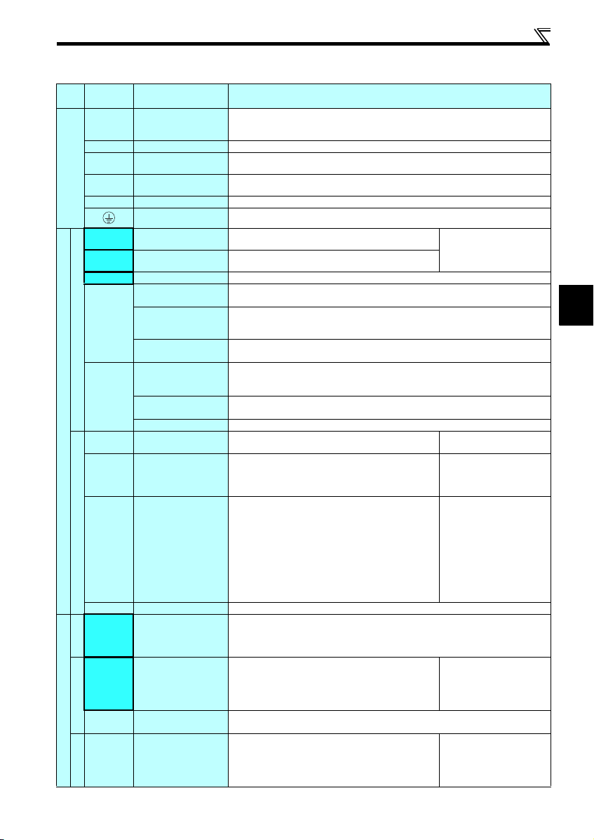
2.3.2 Terminal specifications
Ter min al
Typ e
Symbol
R/L1, S/L2,
T/L3
U, V, W Drive unit output
P/+, PR Brake resistor connectio n
P/+, N/- Brake unit connection
Main circuit terminal
P/+, P1 DC r eactor connection
STF Forward rotation start
STR Reverse rotation start
RH, RM, RL Mu lti-speed se lection Multi-speed can be selected according to the combination of RH, RM and RL signals.
SD
Contact input
PC
10
2 Speed setting (voltage)
Control circuit terminal /Input signal
Speed setting
4 Speed setting (current)
5 Speed setting common Speed setting signal (terminal 2, 4) common terminal. Do not earth (ground).
A, B, C
Relay
RUN Drive unit running
Open collector
SE
FM For mete r
Control circuit terminal/Ou tput signal
Pulse
Terminal Name Terminal Specification
Connect t o the comme rcial pow er supply.
AC power input
Do not connect anything to these terminals when using the high power factor converter (FR-HC)
or power regeneration common converter (FR-CV).
Connect a dedicated PM motor.
Connect a brake resistor (FR-ABR, MRS type, MYS type) across terminals P/+ and PR.
(The brake resistor can not be connected to the 0.2K.)
Connect the brake unit (FR-BU2), power regeneration common converter (FR-CV) or high power
factor converter (FR-HC).
Remove the jumper across terminals P/+ and P1 and connect a DC reactor.
Earth (Ground) For earthing (grounding) the drive unit chassis. Must be earthed (grounded).
Turn ON the STF sign al to start forward rotation an d turn it OFF
to stop.
Turn ON the STR sign al to start rever se rotation and turn it
OFF to stop.
Contact input common
(sink) (initial setting)
External transistor
common (source)
24VDC power supply
common
External transistor
common (sink)
(initial setting)
Contact input common
(source)
24VDC power supply
Speed setting power
supply
Relay output
(fault output)
Open collector output
common
Common terminal for contact input terminal (sink logic) and terminal FM.
Connect this terminal to the power supply common terminal of a transistor output (open collector
output) device, such as a programmable controller, in the source logic to avoid malfunction by
undesirable current.
Common output terminal for 24VDC 0.1A power supply (PC terminal).
Isolated fr om terminals 5 an d SE.
Connect this terminal to the power supply common terminal of a transistor output (open collector
output) device, such as a programmable controller, in the sink logic to avoid malfunction by
undesirable current.
Common terminal for contact input terminal (source logic).
Can be used as 24VDC 0.1A power supply.
Used as power supply when connecting potentiometer for
speed setting (speed setting) from outside of the drive unit.
Inputting 0 to 5VDC (or 0 to 10V) provides the maximum
rotation speed at 5V (10V) and makes input and output
proportional. Use Pr. 73 to switch between in put 0 to 5VDC
input (initial setting) and 0 to 10VDC.
Inputting 4 to 20mADC (or 0 to 5V, 0 to 10V) provides the
maximum rotation speed at 20mA and makes input and output
proportional. This input signal is valid only when the AU signal
is ON (terminal 2 input is invalid). To use terminal 4 (initial
setting is current input), set "4" in any of Pr.178 to Pr.182 (input
terminal function selection) to assign the function, and turn ON
AU signal.
Use Pr. 267 to switch among input 4 to 20mA (initial setting), 0
to 5VDC and 0 to 10VDC. Set the voltage/current input switch
in the "V" posit ion to select v oltage input (0 to 5V/0 to 10V).
1 changeover contact output indicates that the drive unit’s protective function has activated and
the output stopped.
Fault: discontinuity across B-C (continuity across A-C),
Normal: continuity across B-C (discontinuity across A-C)
Switched Low when the drive unit rotation speed is equal to or
higher than the 1r/min. Switched High during stop or DC
injection brake operation.
(Low is when the op en collector output tra nsistor is ON (conducts).
High is when the tr ansistor i s OFF (does not condu ct).)
Common terminal of terminal RUN.
Used to output a selected monitored item (such as Rotation
speed) among several monitored items.
(Not output during drive unit reset.)
The output signal is proportional to the magnitude of the
corresponding monitored item.
Wiring
When the STF and STR signals
are turned ON simultaneously,
the stop command is given.
5VDC
permissible load current 10mA
Input resistance10kΩ ± 1kΩ
Permissible maximum voltage
20VDC
Current input:
Input resistance 249Ω ± 5Ω
Maximum permissible current
30mA
Voltage input:
Input resistance10kΩ ± 1kΩ
Permissible maximum voltage
20VDC
Permissible load 24VDC
(maximum 27 VDC) 0.1A
(a voltage drop is 3.4V m aximum
when the signal is ON)
Permissible load current 1mA
1440 pulses/s at 3000r/min
2
9

Wiring
Terminal
Typ e
Symbol
— PU connecto r
Communication
NOTE
y To change the input specification for terminal 4, set Pr. 267 and the voltage/current input switch correctly, then input
the analog signal relevant to the setting. Applying a voltage with voltage/current input switch in "I" position (current
input is selected) or a current with switch in "V" position (voltage input is selected) could cause component damage
to the drive unit or analog circuit of output devices.
y Connecting the power supply to the drive unit output terminals (U, V, W) will damage the drive unit. Do not perform
such wiring.
y indicates that terminal functions can be selected using Pr. 178 to Pr. 182, Pr. 190, Pr. 192, Pr. 197 (I/O terminal
function selection).
y The terminal names and functions shown here are the initial settings.
y The terminals S1, S2, SC, and SO are for manufacturer setting. Do not connect anything to these. Doing so may cause
a drive unit failure.
Do not remove the shortenin g wires across the termina ls S1 and SC and the termina ls S2 and SC. Removing either of
these shortening wires disables the drive unit operation.
Terminal Name Terminal Specification
With the PU connector, communication can be established through RS-485.
yConforming standard: EIA-485 (RS-485)
yTransmission format: Multidrop link
yCommunication speed: 4800 to 38400bps
yOverall length: 500m
10
Wiring
r
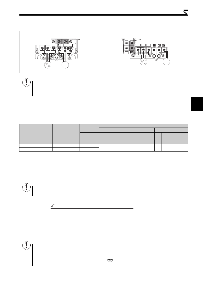
2.3.3 Terminal arrangement of the main circuit terminal, power supply and the motor wiring
zThree-phase 200V class
FR-D720-0.2K to 0.75K- G FR-D720-1.5K to 3.7K-G
N/-
PR
P/+
Jumper
R/L1 S/L2 T/L3
N/-
R/L1 S/L2 T/L3
Jumpe
P/+ PR
IM
MotorPower supply
Power supply
IM
Motor
NOTE
y Make sure the power cables are connected to the R/L1, S/L2, T/L3. (Phase need not be matched.) Never connect the
power cable to the U, V, W of the drive unit. Doing so will damage the drive unit.
y Connect the motor to U, V, W. Turning ON the forward rotation switch (signal) at this time rotates the motor
counterclockwise when viewed from the load shaft.
(1) Cable size and other specifications of the main circuit terminals and the earthing terminal
Select the recommended cable size to ensure that a voltage drop will be 2% or less.
If the wiring distance is long between the drive unit and motor, a main circuit cable voltage drop will cause the motor torque to
decrease especially at the output of a low speed.
The following table indicates a selection example for the wiring length of 20m.
Three-phase 200V class (when input power supply is 220V)
cable
Cable Size
AWG ∗2
R/L1
S/L2
U, V, W
T/L3
PVC Cables, etc. (mm2)
R/L1
S/L2
T/L3
U, V, W
Earthing
(grounding)
cable
Crimping
N·m
Ter min al
R/L1
S/L2
T/L3
HIV Cables, etc. (mm2) ∗1
R/L1
U, V, W
S/L2
T/L3
2 2 2 14 14 2.5 2.5 2.5
U, V, W
Earthing
(grounding)
Ter mi nal
Applicable Drive unit
Model
FR-D720-0.2K to 0.75K- G M 3.5 1 .2 2-3.5 2-3.5
FR-D720-1.5K, 3.7K-G M4 1.5 2-4 2-4
∗1 The cable size is that of the cable (HIV cable (600V class 2 vinyl-insulated cable) etc.) with continuous maximum permissible temperature of 75°C. Assumes
that the surrounding air temperature is 50°C or less and the wiring distance is 20m or less.
∗2 The recommended cable size is that of the cable (THHW cable) with continuous maximum permissible temperature of 75°C. Assumes that the surrounding
air temperature is 40°C or less and the wiring distance is 20m or less.
(Selection example for use mainly in the United States.)
∗3 The recommended cable size is that of the cable (PVC cable) with continuous maximum permissible temperature of 70°C. Assumes that the surrounding air
temperature is 40°C or less and the wiring distance is 20m or less.
(Selection example for use mainly in Europe.)
∗4 The terminal screw size indicates the terminal size for R/L1, S/L2, T/L3, U, V, W, PR, P/+, N/-, P1 and a screw for earthing (grounding).
Screw
Size ∗4
Tightening
Torque
NOTE
y
Tighten the terminal screw to the specified torque. A screw that has been tightened too loosely can cause a short circuit or
malfunction. A screw that has been tightened too tightly can cause a short circuit or malfunction due to the unit breakage.
y Use crimping terminals with insulation sleeve to wire the power supply and motor.
The line voltage drop can be calculated by the following formula:
Line voltage drop [V]=
Use a larger diameter cable when the wiring distance is long or when it is desired to decrease the voltage drop (torque
reduction) in the low speed range.
3 × wire resistance[mΩ/m] × wiring distance[m] × current[A]
1000
2
∗3
(2) Total wiring length
Connect a PM motor within the total wiring length of 30m.
Use one dedicated PM motor for one drive unit. Multiple PM motors cannot be connected to a drive unit.
NOTE
y Especially for long-distance wiring, the drive unit may be affected by a charging current caused by the stray
capacitances of the wiring, leading to a malfunction of the overcurrent protective function, fast response current limit
function, or stall prevention function or a malfunction or fault of the equipment connected on the drive unit output
side. If malfunction of fast-response current limit function occurs, disable this function. If malfunction of stall
prevention function occurs, in crease the stall level. ( Refer to Pr. 22 Stall prevention operation level and Pr. 156 Stall
prevention operation selection in Chapter 4 of the Instruction Manual (Applied))
11
Wiring
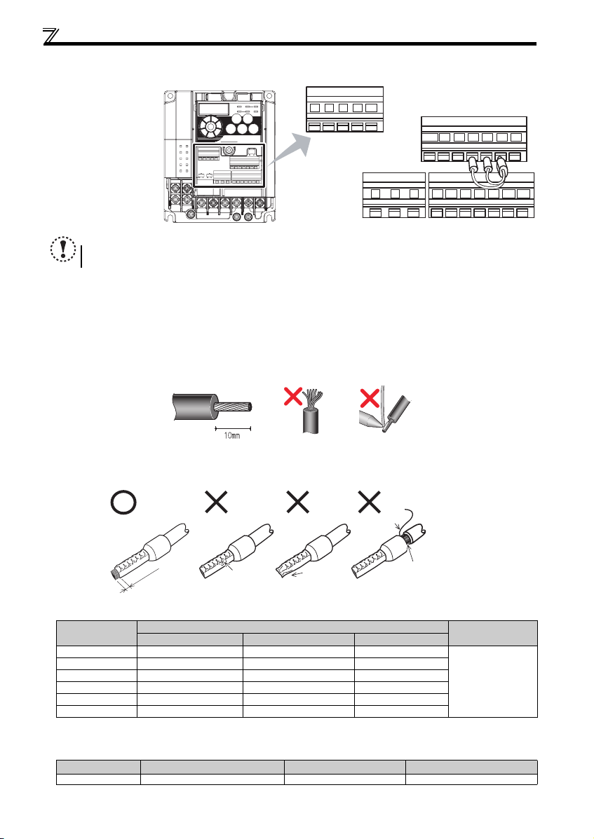
2.3.4 Wiring of control circuit
(1) Control circuit terminal layout
Recommend wire size:
0.3mm
2
to 0.75mm
2
10 2 5 4
FM
RUN SE S1 S2 SCSO
SD
CBA
STF
PCSDRHRMRL
STR
NOTE
y Do not remove the shortenin g wires across the termina ls S1 and SC and the termina ls S2 and SC. Removing either of
these shortening wires disables the drive unit operation.
(2) Wiring method
zWiring
Use a blade terminal and a wire with a sheath stripped off for the control circuit wiring. For a single wire, strip off the sheath of
the wire and apply directly.
Insert the blade terminal or the single wire into a socket of the terminal.
1) Strip off the sheath about the length below. If the length of the sheath peeled is too long, a short circuit may occur
among neighboring wires. If the length is too short, wires might come off.
Wire the stripped wire after twisting it to prevent it from becoming loose. In addition, do not solder it.
2) Crimp the blade terminal.
Insert wires to a blade terminal, and check that the wires come out for about 0 to 0.5 mm from a sleeve.
Check the condition of the blade terminal after crimping. Do not use a blade terminal of which the crimping is
inappropriate, or t he face is damage d.
Blade termin als available on the market: (as of Febr uary 2012)
zPhoenix Contact Co.,Ltd.
Wire Size (mm2)
0.3 AI 0,5-10WH — —
0.5 AI 0,5-10WH — AI 0,5-10WH-GB
0.75 AI 0,75-10G Y A 0,75-10 AI 0,75-10GY-GB
1 AI 1-10RD A1-10 AI 1-10RD/1000GB
1.25, 1.5 AI 1,5-10BK A1,5-10 AI 1,5-10BK/1000GB
0.75 (for two wires) AI-TWIN 2 x 0,75-10GY — —
∗1 A blade terminal with an insulation sleeve compatible with MTW wire which has a thick wire insulation
∗2 Applicable for terminal ABC.
zNICHIFU Co.,Ltd.
Wire Size (mm2)
0.3 to 0.75 BT 0.75-11 VC 0.75 NH 69
Wire stripping length
Unstranded
wires
Sleeve
0 to 0.5mm
Shell
e
ir
W
Damaged
Crumpled tip
Blade Terminal Model
with insulation sleeve without insulation sleeve for UL wire ∗1
Blade terminal product number Insulation product number
Wires are not inserted
into the shell
Crimping Tool
Name
CRIMPFOX 6
∗2
Crimping Tool Product Number
12
 Loading...