

Mitsubishi FR-CS84-230, FR-CS84-120, FR-CS84-295, FR-CS82S-025, FR-CS84-080 Instruction Manual
...
INVERTER
FREQROL-CS80
INSTRUCTION MANUAL (DETAILED)
FR-CS84-012 to 295
FR-CS82S-025 to 100

Safety instructions. . . . . . . . . . . . . . . . . . . . . . . . . . . . . . . . . . . . . . . . . . . . . . . . . . . . . . . . . . . . . . . . . 6
Chapter 1 INTRODUCTION . . . . . . . . . . . . . . . . . . . . . . . . . . . . . . 12
1.1 Product checking and accessories . . . . . . . . . . . . . . . . . . . . . . . . . . . . . . . . . . . . . . . . . . . . . 13
1.2 Component names . . . . . . . . . . . . . . . . . . . . . . . . . . . . . . . . . . . . . . . . . . . . . . . . . . . . . . . . . 14
1.3 About the related manuals. . . . . . . . . . . . . . . . . . . . . . . . . . . . . . . . . . . . . . . . . . . . . . . . . . . . 14
Chapter 2 INSTALLATION AND WIRING . . . . . . . . . . . . . . . . . . . 16
2.1 Peripheral devices . . . . . . . . . . . . . . . . . . . . . . . . . . . . . . . . . . . . . . . . . . . . . . . . . . . . . . . . . . 16
2.1.1 Inverter and peripheral devices. . . . . . . . . . . . . . . . . . . . . . . . . . . . . . . . . . . . . . . . . . . . . . . . . . . . . . . . . . . . . . . . . . . . . . 16
2.1.2 Peripheral devices. . . . . . . . . . . . . . . . . . . . . . . . . . . . . . . . . . . . . . . . . . . . . . . . . . . . . . . . . . . . . . . . . . . . . . . . . . . . . . . . 18
2.2 Removal and reinstallation of the wiring cover . . . . . . . . . . . . . . . . . . . . . . . . . . . . . . . . . . . . 20
CONTENTS
2.3 Installation of the inverter and enclosure design . . . . . . . . . . . . . . . . . . . . . . . . . . . . . . . . . . . 23
2.3.1 Inverter installation environment . . . . . . . . . . . . . . . . . . . . . . . . . . . . . . . . . . . . . . . . . . . . . . . . . . . . . . . . . . . . . . . . . . . . . 23
2.3.2 Amount of heat generated by the inverter. . . . . . . . . . . . . . . . . . . . . . . . . . . . . . . . . . . . . . . . . . . . . . . . . . . . . . . . . . . . . . 25
2.3.3 Cooling system types for inverter enclosure . . . . . . . . . . . . . . . . . . . . . . . . . . . . . . . . . . . . . . . . . . . . . . . . . . . . . . . . . . . . 26
2.3.4 Inverter installation . . . . . . . . . . . . . . . . . . . . . . . . . . . . . . . . . . . . . . . . . . . . . . . . . . . . . . . . . . . . . . . . . . . . . . . . . . . . . . . 27
2.4 Terminal connection diagrams. . . . . . . . . . . . . . . . . . . . . . . . . . . . . . . . . . . . . . . . . . . . . . . . . 29
2.5 Main circuit terminals . . . . . . . . . . . . . . . . . . . . . . . . . . . . . . . . . . . . . . . . . . . . . . . . . . . . . . . . 31
2.5.1 Details on the main circuit terminals . . . . . . . . . . . . . . . . . . . . . . . . . . . . . . . . . . . . . . . . . . . . . . . . . . . . . . . . . . . . . . . . . . 31
2.5.2 Terminal layout of the main circuit terminals, wiring of power supply and the motor . . . . . . . . . . . . . . . . . . . . . . . . . . . . . 31
2.5.3 Applicable cables and wiring length . . . . . . . . . . . . . . . . . . . . . . . . . . . . . . . . . . . . . . . . . . . . . . . . . . . . . . . . . . . . . . . . . . 32
2.5.4 Earthing (grounding) precautions . . . . . . . . . . . . . . . . . . . . . . . . . . . . . . . . . . . . . . . . . . . . . . . . . . . . . . . . . . . . . . . . . . . . 33
2.6 Control circuit. . . . . . . . . . . . . . . . . . . . . . . . . . . . . . . . . . . . . . . . . . . . . . . . . . . . . . . . . . . . . . 35
2.6.1 Details on the control circuit terminals . . . . . . . . . . . . . . . . . . . . . . . . . . . . . . . . . . . . . . . . . . . . . . . . . . . . . . . . . . . . . . . . 35
2.6.2 Control logic (sink/source) change . . . . . . . . . . . . . . . . . . . . . . . . . . . . . . . . . . . . . . . . . . . . . . . . . . . . . . . . . . . . . . . . . . . 36
2.6.3 Wiring of control circuit . . . . . . . . . . . . . . . . . . . . . . . . . . . . . . . . . . . . . . . . . . . . . . . . . . . . . . . . . . . . . . . . . . . . . . . . . . . . 38
2.6.4 Wiring precautions . . . . . . . . . . . . . . . . . . . . . . . . . . . . . . . . . . . . . . . . . . . . . . . . . . . . . . . . . . . . . . . . . . . . . . . . . . . . . . . 40
2.7 Communication connectors and terminals. . . . . . . . . . . . . . . . . . . . . . . . . . . . . . . . . . . . . . . . 41
2.7.1 PU connector . . . . . . . . . . . . . . . . . . . . . . . . . . . . . . . . . . . . . . . . . . . . . . . . . . . . . . . . . . . . . . . . . . . . . . . . . . . . . . . . . . . 41
2.8 Connection of stand-alone option units . . . . . . . . . . . . . . . . . . . . . . . . . . . . . . . . . . . . . . . . . . 42
2.8.1 Connection of the brake unit (FR-BU2) . . . . . . . . . . . . . . . . . . . . . . . . . . . . . . . . . . . . . . . . . . . . . . . . . . . . . . . . . . . . . . . . 42
2.8.2 Connection of the high power factor converter (FR-HC2). . . . . . . . . . . . . . . . . . . . . . . . . . . . . . . . . . . . . . . . . . . . . . . . . . 44
2.8.3 Connection of the power regeneration common converter (FR-CV). . . . . . . . . . . . . . . . . . . . . . . . . . . . . . . . . . . . . . . . . . 45
Chapter 3 PRECAUTIONS FOR USE OF THE INVERTER . . . . . 48
3.1 Electro-magnetic interference (EMI) and leakage currents . . . . . . . . . . . . . . . . . . . . . . . . . . . 48
1

3.1.1 Leakage currents and countermeasures. . . . . . . . . . . . . . . . . . . . . . . . . . . . . . . . . . . . . . . . . . . . . . . . . . . . . . . . . . . . . . . 48
3.1.2 Countermeasures against inverter-generated EMI . . . . . . . . . . . . . . . . . . . . . . . . . . . . . . . . . . . . . . . . . . . . . . . . . . . . . . . 50
3.2 Power supply harmonics . . . . . . . . . . . . . . . . . . . . . . . . . . . . . . . . . . . . . . . . . . . . . . . . . . . . .53
3.2.1 Power supply harmonics . . . . . . . . . . . . . . . . . . . . . . . . . . . . . . . . . . . . . . . . . . . . . . . . . . . . . . . . . . . . . . . . . . . . . . . . . . . 53
3.2.2 Harmonic suppression guidelines in Japan. . . . . . . . . . . . . . . . . . . . . . . . . . . . . . . . . . . . . . . . . . . . . . . . . . . . . . . . . . . . . 53
3.3 Installation of a reactor . . . . . . . . . . . . . . . . . . . . . . . . . . . . . . . . . . . . . . . . . . . . . . . . . . . . . . . 57
3.4 Power shutdown and magnetic contactor (MC) . . . . . . . . . . . . . . . . . . . . . . . . . . . . . . . . . . . . 58
3.5 Countermeasures against deterioration of the 400 V class motor insulation . . . . . . . . . . . . . . 59
3.6 Checklist before starting operation. . . . . . . . . . . . . . . . . . . . . . . . . . . . . . . . . . . . . . . . . . . . . .60
3.7 Failsafe system which uses the inverter. . . . . . . . . . . . . . . . . . . . . . . . . . . . . . . . . . . . . . . . . .62
Chapter 4 BASIC OPERATION . . . . . . . . . . . . . . . . . . . . . . . . . . 66
4.1 Operation panel . . . . . . . . . . . . . . . . . . . . . . . . . . . . . . . . . . . . . . . . . . . . . . . . . . . . . . . . . . . .66
4.1.1 Components of the operation panel . . . . . . . . . . . . . . . . . . . . . . . . . . . . . . . . . . . . . . . . . . . . . . . . . . . . . . . . . . . . . . . . . . 66
4.1.2 Basic operation of the operation panel . . . . . . . . . . . . . . . . . . . . . . . . . . . . . . . . . . . . . . . . . . . . . . . . . . . . . . . . . . . . . . . . 67
4.1.3 Digital characters and their corresponding printed equivalents . . . . . . . . . . . . . . . . . . . . . . . . . . . . . . . . . . . . . . . . . . . . . 68
4.1.4 Changing the parameter setting value . . . . . . . . . . . . . . . . . . . . . . . . . . . . . . . . . . . . . . . . . . . . . . . . . . . . . . . . . . . . . . . . 69
4.2 Monitoring the inverter . . . . . . . . . . . . . . . . . . . . . . . . . . . . . . . . . . . . . . . . . . . . . . . . . . . . . . .70
4.2.1 Monitoring of output current or output voltage . . . . . . . . . . . . . . . . . . . . . . . . . . . . . . . . . . . . . . . . . . . . . . . . . . . . . . . . . . 70
Chapter 5 PARAMETERS. . . . . . . . . . . . . . . . . . . . . . . . . . . . . . . 72
5.1 Parameter list . . . . . . . . . . . . . . . . . . . . . . . . . . . . . . . . . . . . . . . . . . . . . . . . . . . . . . . . . . . . . .72
5.1.1 Parameter list (by parameter number) . . . . . . . . . . . . . . . . . . . . . . . . . . . . . . . . . . . . . . . . . . . . . . . . . . . . . . . . . . . . . . . . 72
5.1.2 Use of a function group number for the identification of parameters . . . . . . . . . . . . . . . . . . . . . . . . . . . . . . . . . . . . . . . . . 79
5.1.3 Parameter list (by function group number) . . . . . . . . . . . . . . . . . . . . . . . . . . . . . . . . . . . . . . . . . . . . . . . . . . . . . . . . . . . . . 81
5.2 Control method. . . . . . . . . . . . . . . . . . . . . . . . . . . . . . . . . . . . . . . . . . . . . . . . . . . . . . . . . . . . .84
5.3 (E) Environment setting parameters. . . . . . . . . . . . . . . . . . . . . . . . . . . . . . . . . . . . . . . . . . . . .85
5.3.1 Reset selection / Disconnected PU detection / PU stop selection . . . . . . . . . . . . . . . . . . . . . . . . . . . . . . . . . . . . . . . . . . . 85
5.3.2 PU display language selection . . . . . . . . . . . . . . . . . . . . . . . . . . . . . . . . . . . . . . . . . . . . . . . . . . . . . . . . . . . . . . . . . . . . . . 87
5.3.3 Beep control . . . . . . . . . . . . . . . . . . . . . . . . . . . . . . . . . . . . . . . . . . . . . . . . . . . . . . . . . . . . . . . . . . . . . . . . . . . . . . . . . . . . 87
5.3.4 PU contrast adjustment. . . . . . . . . . . . . . . . . . . . . . . . . . . . . . . . . . . . . . . . . . . . . . . . . . . . . . . . . . . . . . . . . . . . . . . . . . . . 88
5.3.5 RUN key rotation direction selection . . . . . . . . . . . . . . . . . . . . . . . . . . . . . . . . . . . . . . . . . . . . . . . . . . . . . . . . . . . . . . . . . . 88
5.3.6 Frequency easy setting function selection/ key lock function selection . . . . . . . . . . . . . . . . . . . . . . . . . . . . . . . . . . . . . . . 88
5.3.7 Parameter write selection . . . . . . . . . . . . . . . . . . . . . . . . . . . . . . . . . . . . . . . . . . . . . . . . . . . . . . . . . . . . . . . . . . . . . . . . . . 89
5.3.8 Password . . . . . . . . . . . . . . . . . . . . . . . . . . . . . . . . . . . . . . . . . . . . . . . . . . . . . . . . . . . . . . . . . . . . . . . . . . . . . . . . . . . . . . 90
5.3.9 PWM carrier frequency and Soft-PWM control . . . . . . . . . . . . . . . . . . . . . . . . . . . . . . . . . . . . . . . . . . . . . . . . . . . . . . . . . . 92
5.4 (F) Setting of acceleration/deceleration time and acceleration/deceleration pattern . . . . . . . .93
5.4.1 Setting the acceleration and deceleration time . . . . . . . . . . . . . . . . . . . . . . . . . . . . . . . . . . . . . . . . . . . . . . . . . . . . . . . . . . 93
5.4.2 Acceleration/deceleration pattern . . . . . . . . . . . . . . . . . . . . . . . . . . . . . . . . . . . . . . . . . . . . . . . . . . . . . . . . . . . . . . . . . . . . 95
5.4.3 Remote setting function . . . . . . . . . . . . . . . . . . . . . . . . . . . . . . . . . . . . . . . . . . . . . . . . . . . . . . . . . . . . . . . . . . . . . . . . . . . 96
2

5.4.4 Starting frequency. . . . . . . . . . . . . . . . . . . . . . . . . . . . . . . . . . . . . . . . . . . . . . . . . . . . . . . . . . . . . . . . . . . . . . . . . . . . . . . . 99
5.5 (D) Operation command and frequency command . . . . . . . . . . . . . . . . . . . . . . . . . . . . . . . . 100
5.5.1 Operation mode selection . . . . . . . . . . . . . . . . . . . . . . . . . . . . . . . . . . . . . . . . . . . . . . . . . . . . . . . . . . . . . . . . . . . . . . . . . 100
5.5.2 Startup of the inverter in the Network operation mode at power-ON . . . . . . . . . . . . . . . . . . . . . . . . . . . . . . . . . . . . . . . . 104
5.5.3 Command interface/source for start command and frequency command during communication operation . . . . . . . . . . 105
5.5.4 Reverse rotation prevention selection . . . . . . . . . . . . . . . . . . . . . . . . . . . . . . . . . . . . . . . . . . . . . . . . . . . . . . . . . . . . . . . . 108
5.5.5 JOG operation. . . . . . . . . . . . . . . . . . . . . . . . . . . . . . . . . . . . . . . . . . . . . . . . . . . . . . . . . . . . . . . . . . . . . . . . . . . . . . . . . . 108
5.5.6 Operation by multi-speed setting . . . . . . . . . . . . . . . . . . . . . . . . . . . . . . . . . . . . . . . . . . . . . . . . . . . . . . . . . . . . . . . . . . . 109
5.6 (H) Protective function parameter . . . . . . . . . . . . . . . . . . . . . . . . . . . . . . . . . . . . . . . . . . . . . 112
5.6.1 Motor overheat protection (electronic thermal O/L relay) . . . . . . . . . . . . . . . . . . . . . . . . . . . . . . . . . . . . . . . . . . . . . . . . . 112
5.6.2 Earth (ground) fault detection at start . . . . . . . . . . . . . . . . . . . . . . . . . . . . . . . . . . . . . . . . . . . . . . . . . . . . . . . . . . . . . . . . 114
5.6.3 Inverter output fault detection enable/disable selection . . . . . . . . . . . . . . . . . . . . . . . . . . . . . . . . . . . . . . . . . . . . . . . . . . 114
5.6.4 Undervoltage detection enable/disable selection . . . . . . . . . . . . . . . . . . . . . . . . . . . . . . . . . . . . . . . . . . . . . . . . . . . . . . . 115
5.6.5 I/O phase loss protection selection . . . . . . . . . . . . . . . . . . . . . . . . . . . . . . . . . . . . . . . . . . . . . . . . . . . . . . . . . . . . . . . . . . 115
5.6.6 Retry function . . . . . . . . . . . . . . . . . . . . . . . . . . . . . . . . . . . . . . . . . . . . . . . . . . . . . . . . . . . . . . . . . . . . . . . . . . . . . . . . . . 115
5.6.7 Limiting the output frequency (maximum/minimum frequency). . . . . . . . . . . . . . . . . . . . . . . . . . . . . . . . . . . . . . . . . . . . . 117
5.6.8 Avoiding machine resonance points (frequency jump) . . . . . . . . . . . . . . . . . . . . . . . . . . . . . . . . . . . . . . . . . . . . . . . . . . . 118
5.6.9 Stall prevention operation . . . . . . . . . . . . . . . . . . . . . . . . . . . . . . . . . . . . . . . . . . . . . . . . . . . . . . . . . . . . . . . . . . . . . . . . . 119
5.7 (M) Item and output signal for monitoring . . . . . . . . . . . . . . . . . . . . . . . . . . . . . . . . . . . . . . . 124
5.7.1 Monitor item selection on operation panel or via communication . . . . . . . . . . . . . . . . . . . . . . . . . . . . . . . . . . . . . . . . . . . 124
5.7.2 Output terminal function selection. . . . . . . . . . . . . . . . . . . . . . . . . . . . . . . . . . . . . . . . . . . . . . . . . . . . . . . . . . . . . . . . . . . 126
5.7.3 Output frequency detection. . . . . . . . . . . . . . . . . . . . . . . . . . . . . . . . . . . . . . . . . . . . . . . . . . . . . . . . . . . . . . . . . . . . . . . . 129
5.7.4 Output current detection function . . . . . . . . . . . . . . . . . . . . . . . . . . . . . . . . . . . . . . . . . . . . . . . . . . . . . . . . . . . . . . . . . . . 129
CONTENTS
5.8 (T) Multi-function input terminal parameters . . . . . . . . . . . . . . . . . . . . . . . . . . . . . . . . . . . . . 131
5.8.1 Analog input selection. . . . . . . . . . . . . . . . . . . . . . . . . . . . . . . . . . . . . . . . . . . . . . . . . . . . . . . . . . . . . . . . . . . . . . . . . . . . 131
5.8.2 Response level of analog input and noise elimination . . . . . . . . . . . . . . . . . . . . . . . . . . . . . . . . . . . . . . . . . . . . . . . . . . . 134
5.8.3 Frequency setting voltage (current) bias and gain . . . . . . . . . . . . . . . . . . . . . . . . . . . . . . . . . . . . . . . . . . . . . . . . . . . . . . 134
5.8.4 Checking of current input on analog input terminal. . . . . . . . . . . . . . . . . . . . . . . . . . . . . . . . . . . . . . . . . . . . . . . . . . . . . . 139
5.8.5 Input terminal function selection . . . . . . . . . . . . . . . . . . . . . . . . . . . . . . . . . . . . . . . . . . . . . . . . . . . . . . . . . . . . . . . . . . . . 142
5.8.6 Inverter output shutoff . . . . . . . . . . . . . . . . . . . . . . . . . . . . . . . . . . . . . . . . . . . . . . . . . . . . . . . . . . . . . . . . . . . . . . . . . . . . 143
5.8.7 Start signal operation selection . . . . . . . . . . . . . . . . . . . . . . . . . . . . . . . . . . . . . . . . . . . . . . . . . . . . . . . . . . . . . . . . . . . . . 145
5.9 (C) Motor constant parameters . . . . . . . . . . . . . . . . . . . . . . . . . . . . . . . . . . . . . . . . . . . . . . . 147
5.9.1 Applied motor . . . . . . . . . . . . . . . . . . . . . . . . . . . . . . . . . . . . . . . . . . . . . . . . . . . . . . . . . . . . . . . . . . . . . . . . . . . . . . . . . . 147
5.9.2 Offline auto tuning . . . . . . . . . . . . . . . . . . . . . . . . . . . . . . . . . . . . . . . . . . . . . . . . . . . . . . . . . . . . . . . . . . . . . . . . . . . . . . . 147
5.10 (A) Application parameters . . . . . . . . . . . . . . . . . . . . . . . . . . . . . . . . . . . . . . . . . . . . . . . . . . 151
5.10.1 Traverse function . . . . . . . . . . . . . . . . . . . . . . . . . . . . . . . . . . . . . . . . . . . . . . . . . . . . . . . . . . . . . . . . . . . . . . . . . . . . . . . 151
5.10.2 PID control . . . . . . . . . . . . . . . . . . . . . . . . . . . . . . . . . . . . . . . . . . . . . . . . . . . . . . . . . . . . . . . . . . . . . . . . . . . . . . . . . . . . 152
5.10.3 Automatic restart after instantaneous power failure . . . . . . . . . . . . . . . . . . . . . . . . . . . . . . . . . . . . . . . . . . . . . . . . . . . . . 159
5.10.4 Power failure time deceleration-to-stop function . . . . . . . . . . . . . . . . . . . . . . . . . . . . . . . . . . . . . . . . . . . . . . . . . . . . . . . . 160
5.11 (N) Communication operation parameters. . . . . . . . . . . . . . . . . . . . . . . . . . . . . . . . . . . . . . . 163
5.11.1 Wiring and configuration of PU connector. . . . . . . . . . . . . . . . . . . . . . . . . . . . . . . . . . . . . . . . . . . . . . . . . . . . . . . . . . . . . 163
5.11.2 Initial setting of operation via communication . . . . . . . . . . . . . . . . . . . . . . . . . . . . . . . . . . . . . . . . . . . . . . . . . . . . . . . . . . 165
5.11.3 Initial settings and specifications of RS-485 communication . . . . . . . . . . . . . . . . . . . . . . . . . . . . . . . . . . . . . . . . . . . . . . 168
5.11.4 Mitsubishi inverter protocol (computer link communication) . . . . . . . . . . . . . . . . . . . . . . . . . . . . . . . . . . . . . . . . . . . . . . . 169
5.11.5 MODBUS RTU communication specification . . . . . . . . . . . . . . . . . . . . . . . . . . . . . . . . . . . . . . . . . . . . . . . . . . . . . . . . . . 182
5.12 (G) Control parameters . . . . . . . . . . . . . . . . . . . . . . . . . . . . . . . . . . . . . . . . . . . . . . . . . . . . . 193
5.12.1 Manual torque boost . . . . . . . . . . . . . . . . . . . . . . . . . . . . . . . . . . . . . . . . . . . . . . . . . . . . . . . . . . . . . . . . . . . . . . . . . . . . . 193
5.12.2 Base frequency voltage. . . . . . . . . . . . . . . . . . . . . . . . . . . . . . . . . . . . . . . . . . . . . . . . . . . . . . . . . . . . . . . . . . . . . . . . . . . 194
5.12.3 Energy saving control . . . . . . . . . . . . . . . . . . . . . . . . . . . . . . . . . . . . . . . . . . . . . . . . . . . . . . . . . . . . . . . . . . . . . . . . . . . . 195
5.12.4 Adjustable 3 points V/F . . . . . . . . . . . . . . . . . . . . . . . . . . . . . . . . . . . . . . . . . . . . . . . . . . . . . . . . . . . . . . . . . . . . . . . . . . . 195
5.12.5 DC injection brake. . . . . . . . . . . . . . . . . . . . . . . . . . . . . . . . . . . . . . . . . . . . . . . . . . . . . . . . . . . . . . . . . . . . . . . . . . . . . . . 197
5.12.6 Stop selection . . . . . . . . . . . . . . . . . . . . . . . . . . . . . . . . . . . . . . . . . . . . . . . . . . . . . . . . . . . . . . . . . . . . . . . . . . . . . . . . . . 198
3

5.12.7 Regeneration avoidance function . . . . . . . . . . . . . . . . . . . . . . . . . . . . . . . . . . . . . . . . . . . . . . . . . . . . . . . . . . . . . . . . . . . 199
5.12.8 Increased magnetic excitation deceleration . . . . . . . . . . . . . . . . . . . . . . . . . . . . . . . . . . . . . . . . . . . . . . . . . . . . . . . . . . . 200
5.12.9 Slip compensation. . . . . . . . . . . . . . . . . . . . . . . . . . . . . . . . . . . . . . . . . . . . . . . . . . . . . . . . . . . . . . . . . . . . . . . . . . . . . . . 202
5.13 Parameter clear / All parameter clear. . . . . . . . . . . . . . . . . . . . . . . . . . . . . . . . . . . . . . . . . . .203
5.14 Checking parameters changed from their initial values (initial value change list) . . . . . . . . . 204
Chapter 6 PROTECTIVE FUNCTIONS . . . . . . . . . . . . . . . . . . . . 206
6.1 Inverter fault and indication . . . . . . . . . . . . . . . . . . . . . . . . . . . . . . . . . . . . . . . . . . . . . . . . . .206
6.2 Reset method for the protective functions . . . . . . . . . . . . . . . . . . . . . . . . . . . . . . . . . . . . . . .207
6.3 Check and clear of the fault history . . . . . . . . . . . . . . . . . . . . . . . . . . . . . . . . . . . . . . . . . . . .208
6.4 List of fault indications . . . . . . . . . . . . . . . . . . . . . . . . . . . . . . . . . . . . . . . . . . . . . . . . . . . . . . 210
6.5 Causes and corrective actions . . . . . . . . . . . . . . . . . . . . . . . . . . . . . . . . . . . . . . . . . . . . . . . .211
6.6 Check first when you have a trouble . . . . . . . . . . . . . . . . . . . . . . . . . . . . . . . . . . . . . . . . . . . 219
6.6.1 Motor does not start . . . . . . . . . . . . . . . . . . . . . . . . . . . . . . . . . . . . . . . . . . . . . . . . . . . . . . . . . . . . . . . . . . . . . . . . . . . . . 219
6.6.2 Motor or machine is making abnormal acoustic noise . . . . . . . . . . . . . . . . . . . . . . . . . . . . . . . . . . . . . . . . . . . . . . . . . . . 222
6.6.3 Motor generates heat abnormally . . . . . . . . . . . . . . . . . . . . . . . . . . . . . . . . . . . . . . . . . . . . . . . . . . . . . . . . . . . . . . . . . . . 222
6.6.4 Motor rotates in the opposite direction . . . . . . . . . . . . . . . . . . . . . . . . . . . . . . . . . . . . . . . . . . . . . . . . . . . . . . . . . . . . . . . 222
6.6.5 Speed greatly differs from the setting . . . . . . . . . . . . . . . . . . . . . . . . . . . . . . . . . . . . . . . . . . . . . . . . . . . . . . . . . . . . . . . . 223
6.6.6 Acceleration/deceleration is not smooth . . . . . . . . . . . . . . . . . . . . . . . . . . . . . . . . . . . . . . . . . . . . . . . . . . . . . . . . . . . . . . 223
6.6.7 Speed varies during operation . . . . . . . . . . . . . . . . . . . . . . . . . . . . . . . . . . . . . . . . . . . . . . . . . . . . . . . . . . . . . . . . . . . . . 224
6.6.8 Operation mode is not changed properly . . . . . . . . . . . . . . . . . . . . . . . . . . . . . . . . . . . . . . . . . . . . . . . . . . . . . . . . . . . . . 224
6.6.9 The motor current is too large . . . . . . . . . . . . . . . . . . . . . . . . . . . . . . . . . . . . . . . . . . . . . . . . . . . . . . . . . . . . . . . . . . . . . . 225
6.6.10 Speed does not accelerate . . . . . . . . . . . . . . . . . . . . . . . . . . . . . . . . . . . . . . . . . . . . . . . . . . . . . . . . . . . . . . . . . . . . . . . . 225
6.6.11 Unable to write parameter setting . . . . . . . . . . . . . . . . . . . . . . . . . . . . . . . . . . . . . . . . . . . . . . . . . . . . . . . . . . . . . . . . . . . 226
Chapter 7 PRECAUTIONS FOR MAINTENANCE AND
INSPECTION . . . . . . . . . . . . . . . . . . . . . . . . . . . . . . . 228
7.1 Inspection item . . . . . . . . . . . . . . . . . . . . . . . . . . . . . . . . . . . . . . . . . . . . . . . . . . . . . . . . . . . .228
7.1.1 Daily inspection. . . . . . . . . . . . . . . . . . . . . . . . . . . . . . . . . . . . . . . . . . . . . . . . . . . . . . . . . . . . . . . . . . . . . . . . . . . . . . . . . 228
7.1.2 Periodic inspection . . . . . . . . . . . . . . . . . . . . . . . . . . . . . . . . . . . . . . . . . . . . . . . . . . . . . . . . . . . . . . . . . . . . . . . . . . . . . . 228
7.1.3 Daily and periodic inspection . . . . . . . . . . . . . . . . . . . . . . . . . . . . . . . . . . . . . . . . . . . . . . . . . . . . . . . . . . . . . . . . . . . . . . 228
7.1.4 Checking the inverter and converter modules. . . . . . . . . . . . . . . . . . . . . . . . . . . . . . . . . . . . . . . . . . . . . . . . . . . . . . . . . . 230
7.1.5 Cleaning . . . . . . . . . . . . . . . . . . . . . . . . . . . . . . . . . . . . . . . . . . . . . . . . . . . . . . . . . . . . . . . . . . . . . . . . . . . . . . . . . . . . . . 231
7.1.6 Lifespan. . . . . . . . . . . . . . . . . . . . . . . . . . . . . . . . . . . . . . . . . . . . . . . . . . . . . . . . . . . . . . . . . . . . . . . . . . . . . . . . . . . . . . . 231
7.2 Measurement of main circuit voltages, currents, and powers . . . . . . . . . . . . . . . . . . . . . . . .232
7.2.1 Measurement of powers . . . . . . . . . . . . . . . . . . . . . . . . . . . . . . . . . . . . . . . . . . . . . . . . . . . . . . . . . . . . . . . . . . . . . . . . . . 234
7.2.2 Measurement of voltages and use of PT . . . . . . . . . . . . . . . . . . . . . . . . . . . . . . . . . . . . . . . . . . . . . . . . . . . . . . . . . . . . . 234
7.2.3 Measurement of currents . . . . . . . . . . . . . . . . . . . . . . . . . . . . . . . . . . . . . . . . . . . . . . . . . . . . . . . . . . . . . . . . . . . . . . . . . 235
7.2.4 Use of CT and transducer. . . . . . . . . . . . . . . . . . . . . . . . . . . . . . . . . . . . . . . . . . . . . . . . . . . . . . . . . . . . . . . . . . . . . . . . . 235
7.2.5 Measurement of inverter input power factor . . . . . . . . . . . . . . . . . . . . . . . . . . . . . . . . . . . . . . . . . . . . . . . . . . . . . . . . . . . 235
7.2.6 Measurement of converter output voltage (between terminals P and N) . . . . . . . . . . . . . . . . . . . . . . . . . . . . . . . . . . . . . 235
7.2.7 Insulation resistance test using megger . . . . . . . . . . . . . . . . . . . . . . . . . . . . . . . . . . . . . . . . . . . . . . . . . . . . . . . . . . . . . . 236
7.2.8 Pressure test . . . . . . . . . . . . . . . . . . . . . . . . . . . . . . . . . . . . . . . . . . . . . . . . . . . . . . . . . . . . . . . . . . . . . . . . . . . . . . . . . . . 236
4

Chapter 8 SPECIFICATIONS . . . . . . . . . . . . . . . . . . . . . . . . . . . 238
8.1 Inverter rating. . . . . . . . . . . . . . . . . . . . . . . . . . . . . . . . . . . . . . . . . . . . . . . . . . . . . . . . . . . . . 238
8.2 Common specifications . . . . . . . . . . . . . . . . . . . . . . . . . . . . . . . . . . . . . . . . . . . . . . . . . . . . . 239
8.3 Outline dimension drawings. . . . . . . . . . . . . . . . . . . . . . . . . . . . . . . . . . . . . . . . . . . . . . . . . . 241
8.3.1 Inverter outline dimension drawings . . . . . . . . . . . . . . . . . . . . . . . . . . . . . . . . . . . . . . . . . . . . . . . . . . . . . . . . . . . . . . . . . 241
CONTENTS
5
Safety instructions
Thank you for choosing Mitsubishi Electric inverter.
This Instruction Manual (Detailed) provides detailed instructions for advanced settings of the FREQROL-CS80 series inverters.
Incorrect handling might cause an unexpected fault. Before using this product, carefully read this Instruction Manual (Detailed)
and the printed instructions supplied with this product to ensure proper use of this product.
Do not attempt to install, operate, maintain or inspect this product until you have read the Instruction Manuals and appended
documents carefully. Do not use this product until you have a full knowledge of this product mechanism, safety information and
instructions.
Installation, operation, maintenance and inspection must be performed by qualified personnel. Here, qualified personnel means
a person who meets all the following conditions:
• A person who possesses a certification in regard with electric appliance handling, or person took a proper engineering
training. Such training may be available at your local Mitsubishi Electric office. Contact your local sales office for schedules
and locations.
• A person who can access operating manuals for the protective devices (for example, light curtain) connected to the safety
control system, or a person who has read these manuals thoroughly and familiarized himself/herself with the protective
devices.
In this Instruction Manual, the safety instruction levels are classified into "WARNING" and "CAUTION".
WARNING
CAUTION
Note that even the level may lead to a serious consequence depending on conditions. Be sure to follow
the instructions of both levels as they are critical to personnel safety.
Incorrect handling may cause hazardous conditions, resulting in death or severe injury.
Incorrect handling may cause hazardous conditions, resulting in medium or slight injury,
or may cause only material damage.
6
Electric shock prevention
WARNING
Do not remove the front cover or the wiring cover while the inverter power is ON, and do not run the inverter with the
front cover or the wiring cover removed as the exposed high voltage terminals or the charging part of the circuitry can
be touched. Otherwise you may get an electric shock.
Even if power is OFF, do not remove the front cover except for wiring or periodic inspection as the inside of the inverter
is charged. Otherwise you may get an electric shock.
Before wiring or inspection, check that the LED display of the operation panel is OFF. Any person who is involved in
wiring or inspection shall wait for 10 minutes or longer after the power supply has been cut off, and check that there are
no residual voltage using a tester or the like. The capacitor is charged with high voltage for some time after power OFF,
and it is dangerous.
The inverter must be earthed (grounded). Earthing (grounding) must conform to the requirements of national and local
safety regulations and electrical code (NEC section 250, IEC 61140 class 1 and other applicable standards). A neutral-
point earthed (grounded) power supply must be used to be compliant with EN standard.
Any person who is involved in wiring or inspection of this product shall be fully competent to do the work.
The product body must be installed before wiring. Otherwise you may get an electric shock or be injured.
Key operations must be performed with dry hands to prevent an electric shock. Otherwise you may get an electric shock.
Do not subject the cables to scratches, excessive stress, heavy loads or pinching. Otherwise you may get an electric
shock.
Do not touch the printed circuit board or handle the cables with wet hands. Otherwise you may get an electric shock.
Fire prevention
CAUTION
The inverter must be installed on a nonflammable wall without any through holes so that nobody touches the heatsink,
etc. on the rear side of the inverter. Installing it on or near flammable material may cause a fire.
If the inverter has become faulty, the inverter power must be switched OFF. A continuous flow of large current may cause
a fire.
Do not connect a resistor directly to the DC terminals P/+ and N/-. Doing so could cause a fire.
Be sure to perform daily and periodic inspections as specified in the Instruction Manual. If this product is used without
any inspection, a burst, breakage, or a fire may occur.
Injury prevention
CAUTION
The voltage applied to each terminal must be as specified in the Instruction Manual. Otherwise burst, damage, etc. may
occur.
The cables must be connected to the correct terminals. Otherwise burst, damage, etc. may occur.
The polarity (+ and -) must be correct. Otherwise burst, damage, etc. may occur.
While power is ON or for some time after power-OFF, do not touch the inverter as it will be extremely hot. Touching these
devices may cause a burn.
7

Additional instructions
The following instructions must be also followed. If the product is handled incorrectly, it may cause unexpected fault, an injury,
or an electric shock.
CAUTION
Transportation and installing
Any person who is opening a package using a sharp object, such as a knife or cutter, must wear gloves to prevent injuries
caused by the edge of the sharp object.
The product must be transported in correct method that corresponds to the weight. Failure to do so may lead to injuries.
Do not stand or place any heavy object on the product.
Do not stack the boxes containing products higher than the number recommended.
When carrying the product, do not hold it by the front cover. Doing so may cause a fall or failure of the product.
During installation, caution must be taken not to drop the inverter as doing so may cause injuries.
The product must be installed on the surface that withstands the weight of the product.
Do not install the product on a hot surface.
The installing orientation of the inverter must be correct.
The inverter must be installed on a strong surface securely with screws so that it does not drop.
Do not install or operate the inverter if it is damaged or has parts missing.
Foreign conductive objects must be prevented from entering the inverter. That includes screws and metal fragments or
other flammable substance such as oil.
As the inverter is a precision instrument, do not drop or subject it to impact.
The surrounding air temperature must be between -10 and +40°C
damaged.
The ambient humidity must be 95% RH or less (non-condensing) for the inverter. Otherwise the inverter may be
damaged. (Refer to page 23 for details.)
The temporary storage temperature (applicable to a short limited time such as a transportation time) must be between -
20 and +65°C. Otherwise the inverter may be damaged.
The inverter must be used indoors (without corrosive gas, flammable gas, oil mist, dust and dirt). Otherwise the inverter
may be damaged.
The inverter must be used at an altitude of 2500 m or less, with 5.9 m/s
Y, Z axes). Otherwise the inverter may be damaged. (For the installation at an altitude above 1000 m, consider a 3%
reduction in the rated current per 500 m increase in altitude. Refer to page 23 for details.)
If halogen-based materials (fluorine, chlorine, bromine, iodine, etc.), included in fumigants to sterilize or disinfect wooden
packages, infiltrate into the product, the product may be damaged. Prevent residual fumigant components from being
infiltrated into the product when packaging, or use an alternative sterilization or disinfection method (heat disinfection,
etc.). Note that sterilization of disinfection of wooden package should be performed before packing the product.
Wiring
Do not install a power factor correction capacitor, surge absorber, or radio noise filter on the inverter's output side. These
devices on the inverter output side may be overheated or burn out.
The output of the inverter (output terminals U, V, W) must be correctly connected to a motor. Otherwise the motor rotates
inversely.
Test operation
Before starting the test operation, confirm or adjust the parameter settings. A failure to do so may cause some machines
to make unexpected motions.
*1
(non-freezing). Otherwise the inverter may be
2
or less vibration at 10 to 55 Hz (directions of X,
8
*1 40 to 50°C (non-freezing) at the rated current reduced by 15%.

WARNING
Usage
Any person must stay away from the motor or machinery when the retry function or the automatic restart after
instantaneous power failure function is set in the inverter as the motor or the machine will restart suddenly after an
inverter fault or instantaneous power failure.
It may happen depending on the inverter's function settings that the inverter does not stop its output even when the
STOP/RESET key on the operation panel is pressed. To prepare for it, provide a separate circuit and switch (to turn the
inverter power OFF, or apply a mechanical brake, etc.) for an emergency stop.
Be sure to turn OFF the start (STF/STR) signal before clearing the fault as the inverter will restart the motor suddenly
after a fault clear.
Use only a three-phase induction motor as a load on this product. Connection of any other electrical equipment to the
inverter output may damage the equipment.
Do not modify the product.
Do not remove any part which is not instructed to be removed in the Instruction Manuals. Doing so may lead to a failure
or damage of the product.
CAUTION
Usage
The electronic thermal O/L relay function may not be enough for protection of a motor from overheating. It is
recommended to install an external thermal relay for overheat protection.
Do not use a magnetic contactor on the inverter input side for frequent starting/stopping of the inverter. Otherwise the
life of the inverter decreases.
Use a noise filter or other means to minimize the electromagnetic interference with other electronic equipment used
nearby the inverter.
Appropriate measures must be taken to suppress harmonics. Otherwise harmonics in power systems generated from
the inverter may heat/damage a power factor correction capacitor or a generator.
For a 400 V class motor driven by the inverter, use an insulation-enhanced motor, or take measures to suppress surge
voltage. Otherwise surge voltage attributable to the line constants may occur at the motor terminals, deteriorating the
insulation of the motor.
As all parameters return to their initial values after the Parameter clear or All parameter clear is performed, the needed
parameters for the inverter operation must be set again before the operation is started.
The inverter can be easily set for high-speed operation. Therefore, consider all things related to the operation such as
the performance of a motor and equipment in a system before the setting change.
Before running an inverter which have been stored and not been operated for a long period, perform an inspection and
a test operation.
To avoid damage to the product due to static electricity, static electricity in your body must be discharged before you
touch the product.
Emergency stop
A safety backup such as an emergency brake must be provided for devices or equipment in a system to prevent
hazardous conditions in case of the inverter failure.
If a breaker on the inverter input side is tripped, the wiring must be checked for a fault (such as short circuit), and internal
parts of the inverter for a damage, etc. Identify and remove the cause of the trip before resetting the tripped breaker (or
before applying the power to the inverter again).
When any protective function is activated, take an appropriate corrective action before resetting the inverter to resume
the operation.
Maintenance, inspection and parts replacement
Do not carry out a megger (insulation resistance) test on the control circuit of the inverter. Doing so will cause a failure.
Disposal
The product must be treated as industrial waste.
9

General instruction
For clarity purpose, illustrations in this Instruction Manual may be drawn with covers or safety guards removed. Ensure
all covers and safety guards are properly installed prior to starting operation.
10

CHAPTER 1
CHAPTER 1
1.1 Product checking and accessories .........................................................................................................................13
1.2 Component names .................................................................................................................................................14
1.3 About the related manuals......................................................................................................................................14
INTRODUCTION
4
5
6
7
8
9
10
11

1 INTRODUCTION
The contents described in this chapter must be read before using this product.
Always read the instructions before use.
Abbreviations
Item Description
Operation panel Operation panel equipped on the inverter
Parameter unit Parameter unit (FR-PU07)
PU
Inverter Mitsubishi Electric FREQROL-CS80 series inverter
Pr. Parameter number (Number assigned to function)
PU operation Operation using the PU (operation panel/parameter unit)
External operation Operation using the control circuit signals
Combined operation Combined operation using the PU (operation panel/parameter unit) and External operation
Mitsubishi Electric standard
motor
Mitsubishi Electric constanttorque motor
Trademarks
• Microsoft and Visual C++ are registered trademarks of Microsoft Corporation in the United States and other countries.
• MODBUS is a registered trademark of SCHNEIDER ELECTRIC USA, INC.
• Other company and product names herein are the trademarks and registered trademarks of their respective owners.
Operation panel on the inverter / enclosure surface operation panel (FR-PA07) / LCD operation panel (FRLU08) / parameter unit
SF-JR
SF-HRCA
Notes on descriptions in this Instruction Manual
• Connection diagrams in this Instruction Manual appear with the control logic of the input terminals as source logic, unless
otherwise specified. (For the control logic, refer to page 36.)
Harmonic Suppression Guidelines
• All the models of the inverters used by specific consumers are covered by "the Harmonic Suppression Guidelines for
Consumers Who Receive High Voltage or Special High Voltage". (For details, refer to page 53.)
1. INTRODUCTION
12
1.1 Product checking and accessories
ᾜᾘᾣᾢᾤᾑᾘᾢᾗᾘẅᾔᾛᾔᾒᾣᾡᾘᾒẅᾓᾐᾛᾘᾐᾝ
ᾘᾝᾓᾤᾢᾣᾡᾘᾐᾛ
ᾔᾛᾔᾒᾣᾡᾘᾒ
ᾜᾘᾣᾢᾤᾑᾘᾢᾗᾘ
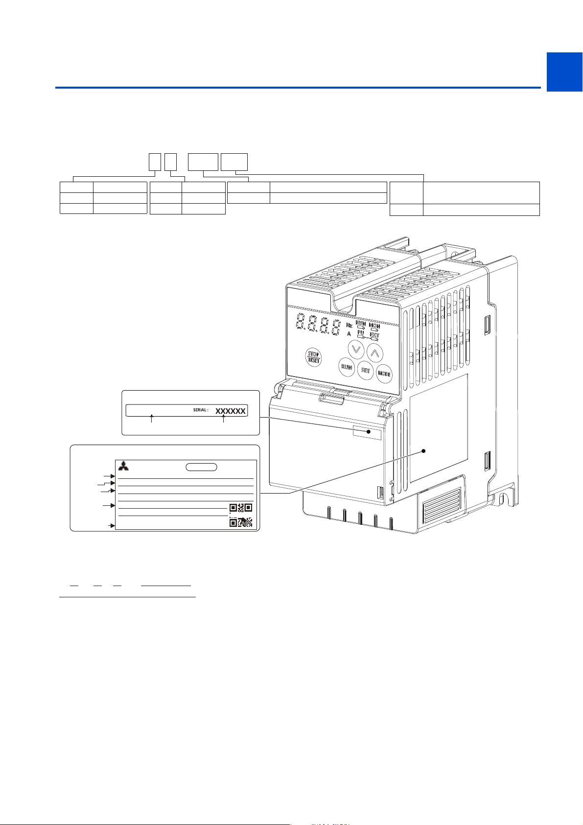
Unpack the product and check the rating plate and the capacity plate of the inverter to ensure that the model agrees with the
order and the product is intact.
Inverter model
1
2
FR--CS 8 4 -60080
Symbol
2
4
Voltage class
200 V class
400 V class
Symbol Voltage
None
S
Capacity plate
FR-CS84-080-60
Inverter model Serial number
Three-phase
Single-phase
Symbol Description
012 to 295 Inverter SLD rated current (A)
Symbol
3
Circuit board coating
(conforming to IEC60721-3-3 3C2/3S2)
With-60
3
5
6
7
8
9
Rating plate
INVERTER
SAMPLE
Inverter model
Input rating
Output rating
Serial number
Country of origin
ᾜᾘᾣᾢᾤᾑᾘᾢᾗᾘ
ᾔᾛᾔᾒᾣᾡᾘᾒ
MODEL FR-CS84-080-60
INPUT : XXXXX
OUTPUT :XXXXX
SERIAL :
ᾜᾘᾣᾢᾤᾑᾘᾢᾗᾘẅᾔᾛᾔᾒᾣᾡᾘᾒẅᾓᾐᾛᾘᾐᾝ
MADE IN CHINA
PASSED
ᾘᾝᾓᾤᾢᾣᾡᾘᾐᾛ
How to read the SERIAL number
Ratingplateexample
□ ○ ○ ○○○○○○
SymbolYearMonth Controlnumber
SERIAL
The SERIAL consists of one symbol, two characters indicating the production year and
month, and six characters indicating the control number.
The last digit of the production year is indicated as the Year, and the Month is indicated
by 1 to 9, X (October), Y (November), or Z (December).
10
1. INTRODUCTION
1.1 Product checking and accessories
13
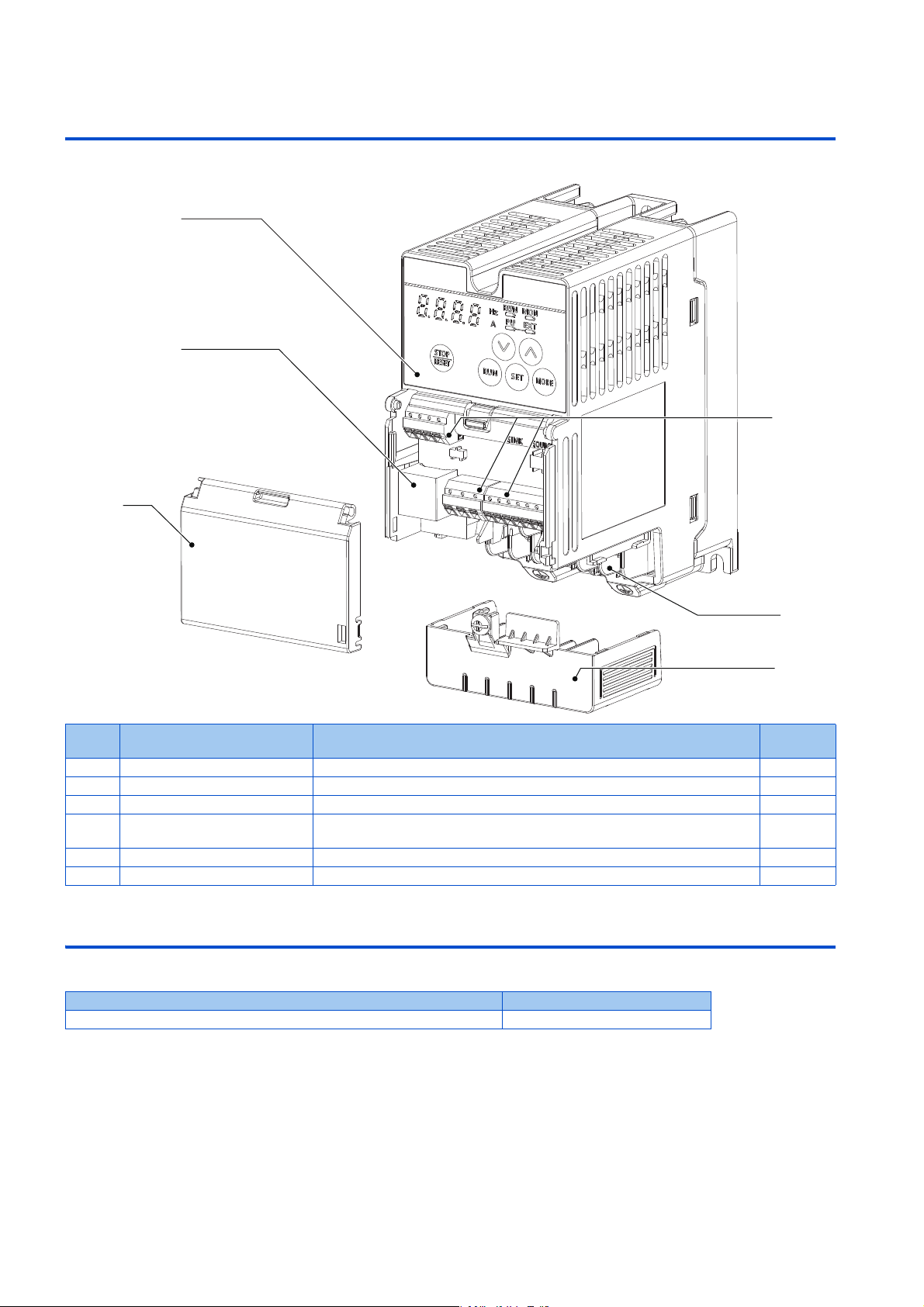
1.2 Component names
(a)
(d)
(f)
(b)
(c)
(e)
Component names are as follows.
Symbol Name Description
(a) Operation panel Operates and monitors the inverter. 41
(b) Control circuit terminal block Connects cables for the control circuit. 35
(c) Main circuit terminal block Connects cables for the main circuit. 31
(d) PU connector
(e) Wiring cover This cover is removable without unplugging cables. 20
(f) Front cover Open this cover for wiring. Do not remove this cover. 20
Connects the operation panel or the parameter unit. This connector also enables
the RS-485 communication.
1.3 About the related manuals
The manual related to FR-CS80 is as follows.
Manual name Manual number
FREQROL-CS80 Instructions and Cautions for Use of Inverters IB-0600720
Refer to
page
41
1. INTRODUCTION
14
1.2 Component names

CHAPTER 2
CHAPTER 2
INSTALLATION AND
WIRING
2.1 Peripheral devices ..................................................................................................................................................16
2.2 Removal and reinstallation of the wiring cover .......................................................................................................20
2.3 Installation of the inverter and enclosure design ....................................................................................................23
2.4 Terminal connection diagrams................................................................................................................................29
2.5 Main circuit terminals ..............................................................................................................................................31
2.6 Control circuit..........................................................................................................................................................35
2.7 Communication connectors and terminals..............................................................................................................41
2.8 Connection of stand-alone option units ..................................................................................................................42
4
5
6
7
8
9
10
15
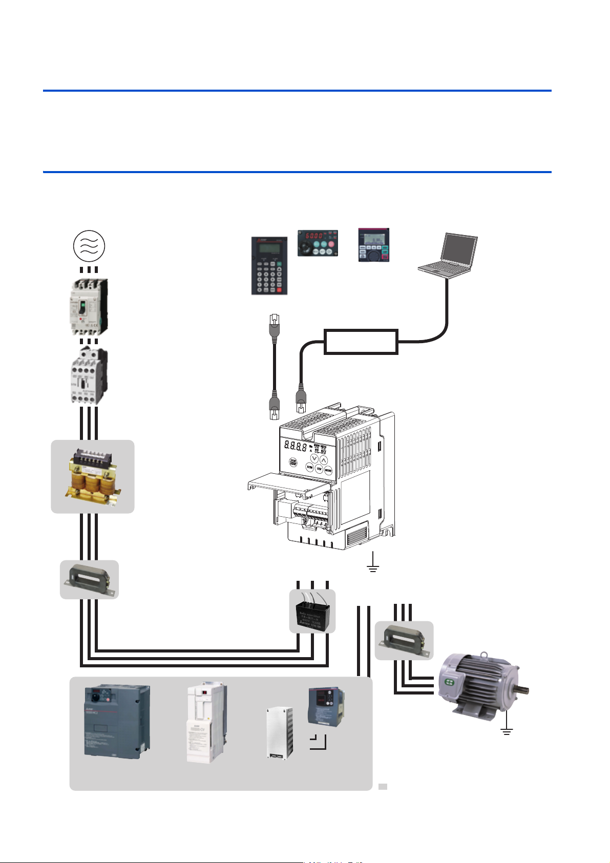
2 INSTALLATION AND WIRING
(a) Inverter
(b) AC power supply
(d) Magnetic contactor (MC)
(l) Noise filter (ferrite core)
(FR-BSF01, FR-BLF)
(m) Induction motor
Earth (Ground)
Earth (Ground)
(g) High power factor
converter (FR-HC2)
(h) Power regeneration
common converter (FR-CV)
(k) Resistor unit
(FR-BR, MT-BR5)
RS-232C - RS-485 converter is
required when connecting to PC
with RS-232C interface.
Earth (Ground)
R/L1 S/L2 T/L3
N/-P/+
UW
V
(e) AC reactor
(FR-HAL)
(f) Noise filter
(FR-BSF01, FR-BLF)
(c) Moulded case circuit breaker
(MCCB) or earth leakage circuit
breaker (ELB), fuse
To prevent an electric shock, always
earth (ground) the motor and inverter.
For reduction of induction noise from
the power line of the inverter, it is
recommended to wire the earth (ground)
cable by returning it to the earth (ground)
terminal of the inverter.
Enclosure surface
operation
panel (FR-PA07)
By connecting the connection
cable (FR-CB2) to the PU
connector, operation can be
performed from FR-PU07,
FR-PA07, FR-LU08.
(i) Radio noise filter
(FR-BIF)
P/+
P/+
PR
PR
(j) Brake unit
(FR-BU2)
RS-485RS-232C
Converter
Parameter unit
(FR-PU07)
: Install these options as required.
LCD operation
panel (FR-LU08)
This chapter explains the installation and the wiring of this product.
Always read the instructions before use.
2.1 Peripheral devices
2.1.1 Inverter and peripheral devices
2. INSTALLATION AND WIRING
16
2.1 Peripheral devices

SymbolName Overview Refer to
page
The life of the inverter is influenced by the surrounding air temperature.
The surrounding air temperature should be as low as possible within the
permissible range. This must be noted especially when the inverter is
(a) Inverter (FREQROL-CS80)
(b) AC power supply Must be within the permissible power supply specifications of the inverter. 238
Molded case circuit breaker (MCCB), earth
(c)
leakage circuit breaker (ELB), or fuse
(d) Magnetic contactor (MC)
(e) AC reactor (FR-HAL)
(f) Noise filter (FR-BLF)
(g) High power factor converter (FR-HC2)
Power regeneration common converter
(h)
(FR-CV)
(i) Radio noise filter (FR-BIF) Install this to reduce the radio noise. —
(j) Brake unit (FR-BU2)
(k) Resistor unit (FR-BR)
Noise filter (ferrite core) (FR-BSF01, FR-
(l)
BLF)
(m) Induction motor Connect a squirrel-cage induction motor. —
installed in an enclosure.
Incorrect wiring may lead to damage of the inverter. The control signal lines
must be kept fully away from the main circuit lines to protect them from
noise.
Must be selected carefully since an inrush current flows in the inverter at
power ON.
Install this to ensure safety.
Do not use this to start and stop the inverter. Doing so will shorten the life
of the inverter.
Install this to suppress harmonics and to improve the power factor.
An AC reactor (FR-HAL) (option) is required when installing the inverter
near a large power supply system (500 kVA or more). Under such condition,
the inverter may be damaged if you do not use a reactor.
Select a reactor according to the applied motor capacity.
Install this to reduce the electromagnetic noise generated from the inverter.
The noise filter is effective in the range from about 0.5 to 5 MHz. A wire
should be wound four turns at maximum.
Suppresses the power supply harmonics significantly. Install this as
required.
Provides a large braking capability. Install this as required. 45
Allows the inverter to provide the optimal regenerative braking capability.
Install this as required.
Install this to reduce the electromagnetic noise generated from the inverter.
The noise filter is effective in the range from about 0.5 to 5 MHz. A wire
should be wound four turns at maximum.
23, 29
18
58
57
50
44
42
—
1
2
3
5
5
6
7
8
9
NOTE
• To prevent an electric shock, always earth (ground) the motor and inverter.
• Do not install a power factor correction capacitor or surge suppressor or capacitor type filter on the inverter's output side. Doing
so will cause the inverter to be shut off or the capacitor and surge suppressor to be damaged. If any of the above devices is
connected, immediately remove it. When installing a molded case circuit breaker on the output side of the inverter, contact the
manufacturer of the molded case circuit breaker.
• Electromagnetic wave interference
The input/output (main circuit) of the inverter includes high frequency components, which may interfere with the
communication devices (such as AM radios) used near the inverter. In such a case, install the optional radio noise filter FR-
BIF (for use in the input side only) or line noise filter FR-BSF01 or FR-BLF to minimize interference. (Refer to page 52).
• For details of options and peripheral devices, refer to the respective Instruction Manual.
10
2. INSTALLATION AND WIRING
2.1 Peripheral devices
17
2.1.2 Peripheral devices
NOTE
Check the model of the inverter you purchased. Appropriate peripheral devices must be selected according to the capacity.
Refer to the following table to prepare appropriate peripheral devices.
Molded case circuit breaker / earth leakage circuit breaker
• This is a matrix showing the rated current of the molded case circuit breaker (MCCB) or earth leakage circuit breaker (ELB)
(NF or NV type) according to the selected inverter and rating.
Voltage Inverter model
FR-CS84-012 5 A 5 A
FR-CS84-022 5 A 5 A
Threephase
400 V
class
Singlephase
200V
class
FR-CS84-036 10 A 10 A
FR-CS84-050 15 A 10 A
FR-CS84-080 20 A 15 A
FR-CS84-120 30 A 20 A
FR-CS84-160 30 A 30 A
FR-CS84-230 50 A 40 A
FR-CS84-295 60 A 50 A
FR-CS82S-025 10 A 5 A
FR-CS82S-042 15 A 10 A
FR-CS82S-070 30 A 15 A
FR-CS82S-100 40 A 30 A
• Select an MCCB according to the power supply capacity.
• Install one MCCB per inverter. For the use in the United States or Canada, provide the appropriate UL and cUL listed fuse that
is suitable for branch circuit protection. (Refer to the FREQROL-CS80 Instructions and Cautions for Use of Inverters.)
MCCB
MCCB
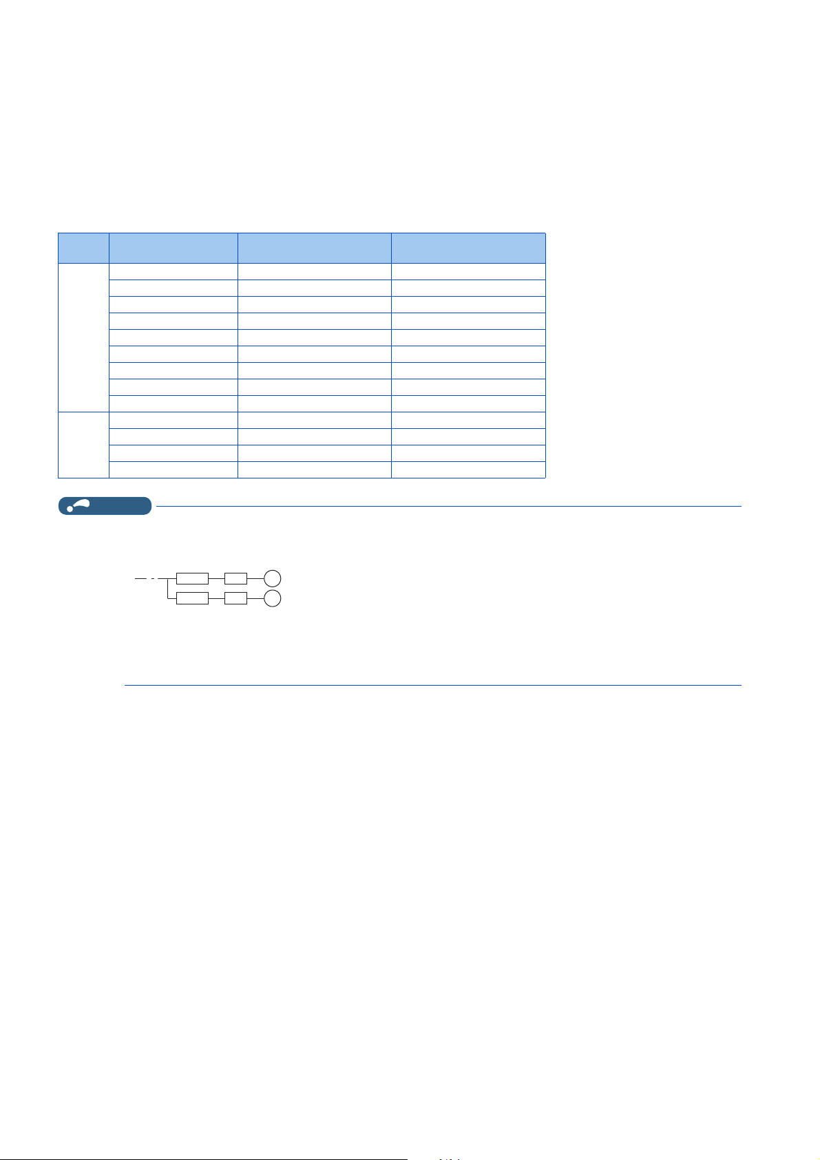
• When the inverter capacity is larger than the motor capacity, select an MCCB and a magnetic contactor according to the
inverter model, and select cables and reactors according to the motor output.
• When the breaker on the inverter's input side trips, check for the wiring fault (short circuit), damage to internal parts of the
inverter etc. The cause of the output shutoff must be identified and removed before turning ON the power of the breaker.
Without the power factor
improving reactor
M
INV
M
INV
With the power factor
improving reactor
2. INSTALLATION AND WIRING
18
2.1 Peripheral devices

Magnetic contactor at the inverter's input line
• This is a matrix showing the model name of the Mitsubishi magnetic contactor to be installed at the inverter's input line
according to the selected inverter and rating.
1
Voltage Inverter model
FR-CS84-012 S-T10 S-T10
FR-CS84-022 S-T10 S-T10
Threephase
400 V
class
Singlephase
200V
class
FR-CS84-036 S-T10 S-T10
FR-CS84-050 S-T10 S-T10
FR-CS84-080 S-T10 S-T10
FR-CS84-120 S-T21 S-T12
FR-CS84-160 S-T21 S-T21
FR-CS84-230 S-T21 S-T21
FR-CS84-295 S-T35 S-T21
FR-CS82S-025 S-T10 S-T10
FR-CS82S-042 S-T10 S-T10
FR-CS82S-070 S-T10 S-T10
FR-CS82S-100 S-T10 S-T10
NOTE
• The matrix shows the magnetic contactor selected according to the standards of Japan Electrical Manufacturers' Association
(JEM standards) for AC-1 class. The electrical durability of magnetic contactor is 500,000 times. When the magnetic contactor
is used for emergency stops during motor driving, the electrical durability is 25 times. If using an MC for emergency stop during
motor driving, select an MC for the inverter input current according to the rated current against JEM 1038 standards for AC-3
class. When installing an MC at the inverter output line to switch to the commercial-power supply operation while running a
general-purpose motor, select an MC for the rated motor current according to the rated current against JEM 1038 standards
for AC-3 class.
• When the inverter capacity is larger than the motor capacity, select an MCCB and a magnetic contactor according to the
inverter model, and select cables and reactors according to the motor output.
• When the breaker on the inverter's input side trips, check for the wiring fault (short circuit), damage to internal parts of the
inverter etc. The cause of the output shutoff must be identified and removed before turning ON the power of the breaker.
Without the power factor
improving reactor
With the power factor
improving reactor
2
3
5
5
6
7
8
9
10
2. INSTALLATION AND WIRING
2.1 Peripheral devices
19
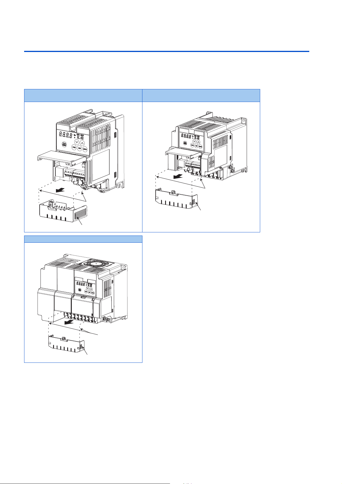
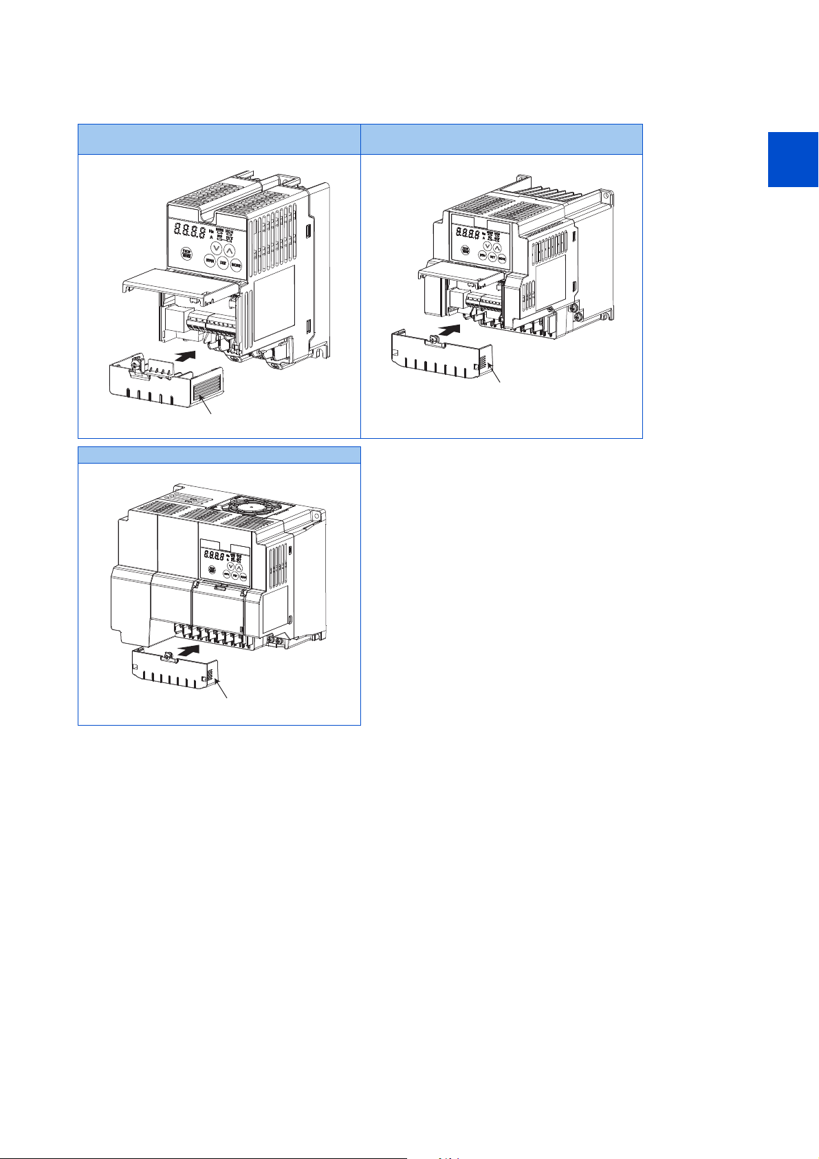
2.2 Removal and reinstallation of the wiring cover
Wiring cover
Guide
Wiring cover
Guide
Wiring cover
Guide
Removal for the FR-CS84-160 or lower and the FR-CS82S inverters
To remove the wiring cover, loosen the mounting screw of the cover, and pull out the cover. For the FR-CS84-012 to 080 or
the FR-CS82S inverter, open the front cover to remove the wiring cover.
FR-CS84-012 and 022
FR-CS82S-025, 042
FR-CS84-120 to 160
FR-CS84-036 to 080
FR-CS82S-070, 100
2. INSTALLATION AND WIRING
20
2.2 Removal and reinstallation of the wiring cover
Reinstallation for the FR-CS84-160 or lower and the FR-CS82S inverters
Wiring cover
Wiring cover
To reinstall the wiring cover, fit the cover to the inverter along the guides. Fasten the cover with the mounting screw.
FR-CS84-012 and 022
FR-CS82S-025, 042
FR-CS84-120 to 160
FR-CS84-036 to 080
FR-CS82S-070, 100
Wiring cover
1
2
3
5
5
6
7
8
9
10
2. INSTALLATION AND WIRING
2.2 Removal and reinstallation of the wiring cover
21
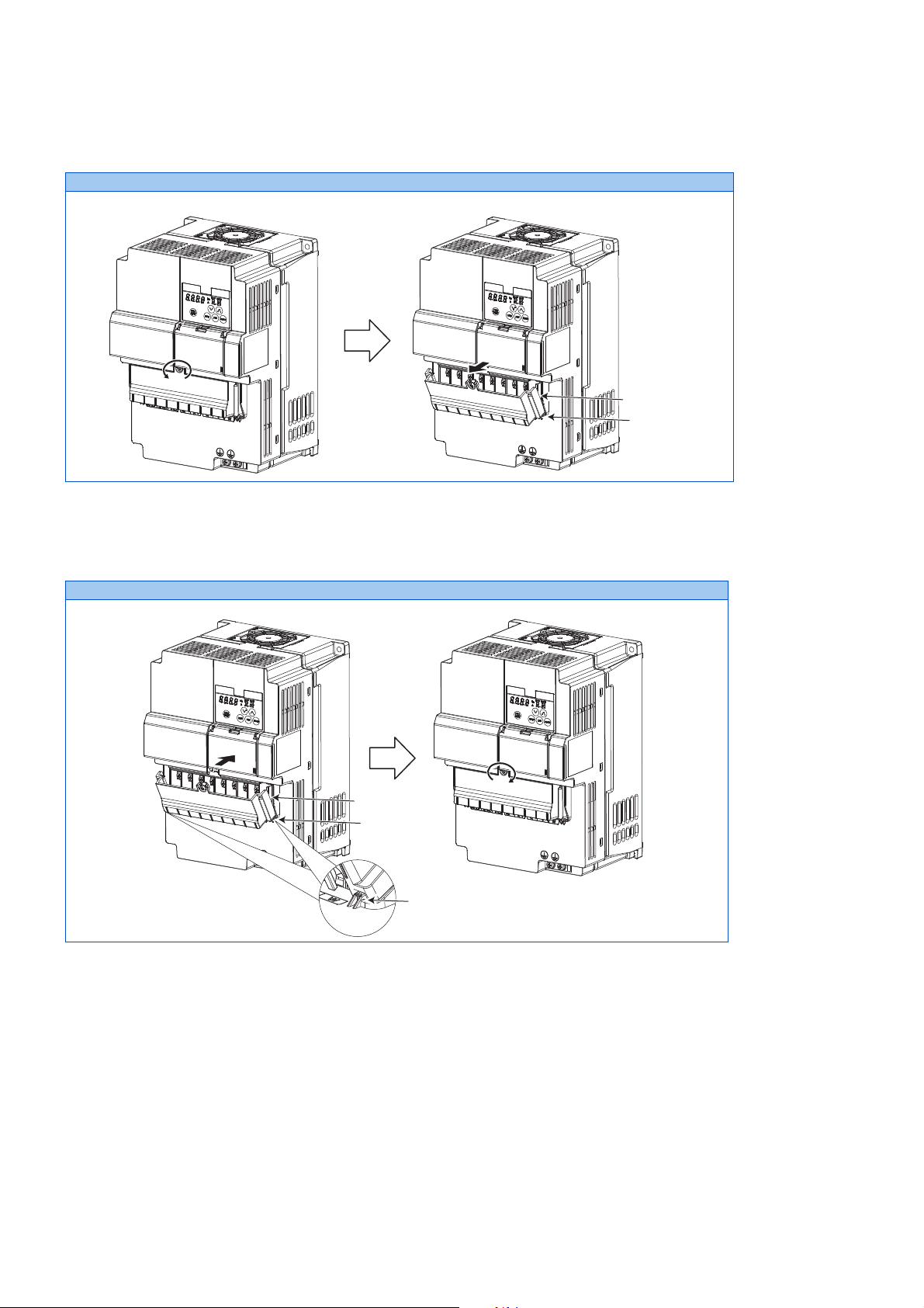
Removal for the FR-CS84-230 or higher inverters
Hook
Wiring cover
sockets
hooks
Wiring cover
To remove the wiring cover, loosen the mounting screw of the cover. While holding the hooks of the inverter, pull out and
remove the cover.
FR-CS84-230 and 295
Reinstallation for the FR-CS84-230 or lower and the FR-CS82S inverters
Fit the two sockets on the bottom of the cover to the hooks on the inverter, and install the cover to the inverter. Fasten the cover
with the mounting screw.
FR-CS84-230 and 295
2. INSTALLATION AND WIRING
22
2.2 Removal and reinstallation of the wiring cover
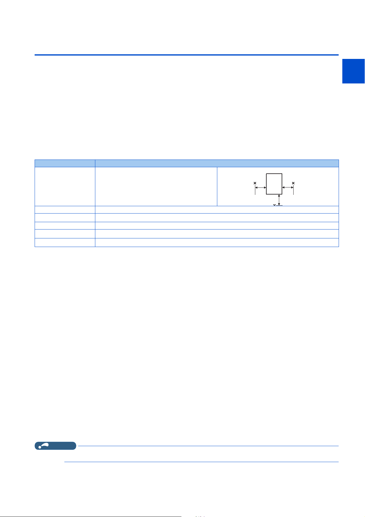
2.3 Installation of the inverter and enclosure design
Measurement
position
Measurement
Inverter
5 cm
5 cm
5 cm
When designing or manufacturing an inverter enclosure, determine the structure, size, and device layout of the enclosure by
fully considering the conditions such as heat generation of the contained devices and the operating environment. An inverter
unit uses many semiconductor devices. To ensure higher reliability and long period of operation, operate the inverter in the
ambient environment that completely satisfies the equipment specifications.
2.3.1 Inverter installation environment
1
2
3
The following table lists the standard specifications of the inverter installation environment. Using the inverter in an environment
that does not satisfy the conditions deteriorates the performance, shortens the life, and causes a failure. Refer to the following
points, and take adequate measures.
Standard environmental specifications of the inverter
Item Description
Surrounding air
temperature
Ambient humidity With circuit board coating (conforming to class 3C2/3S2 in IEC 60721-3-3): 95% RH or less (non-condensing)
Storage temperature
Atmosphere Indoors (free from corrosive gas, flammable gas, oil mist, dust and dirt)
Altitude
Vibration
*1 -40 to 50°C (non-freezing) at the rated current reduced by 15%.
*2 Temperature applicable for a short time, for example, in transit.
*3 For the installation at an altitude above 1000 m, consider a 3% reduction in the rated current per 500 m increase in altitude.
-10 to +40°C (non-freezing)
-20 to +65°C
2500 m or lower
5.9 m/s
*2
*3
2
or less at 10 to 55 Hz (directions of X, Y, Z axes)
*1
Temperature
The permissible surrounding air temperature of the inverter is between -10 and +40°C. Always operate the inverter within this
temperature range. Operation outside this range will considerably shorten the service lives of the semiconductors, parts,
capacitors and others. Take the following measures to keep the surrounding air temperature of the inverter within the specified
range.
5
5
6
7
8
9
10
Measures against high temperature
• Use a forced ventilation system or similar cooling system. (Refer to page 26.)
• Install the enclosure in an air-conditioned electric chamber.
• Block direct sunlight.
• Provide a shield or similar plate to avoid direct exposure to the radiated heat and wind of a heat source.
• Ventilate the area around the enclosure well.
Measures against low temperature
• Provide a space heater in the enclosure.
• Do not power OFF the inverter. (Keep the start signal of the inverter OFF.)
Sudden temperature changes
• Select an installation place where temperature does not change suddenly.
• Avoid installing the inverter near the air outlet of an air conditioner.
• If temperature changes are caused by opening/closing of a door, install the inverter away from the door.
NOTE
• For the amount of heat generated by the inverter unit, refer to page 25.
2.3 Installation of the inverter and enclosure design
2. INSTALLATION AND WIRING
23

Humidity
Operate the inverter within the ambient air humidity of usually up to 95% with circuit board coating. Too high humidity will pose
problems of reduced insulation and metal corrosion. On the other hand, too low humidity may cause a spatial electrical
breakdown. The humidity conditions for the insulation distance defined in JEM 1103 standard "Insulation Distance from Control
Equipment" is 45 to 85%.
Measures against high humidity
• Make the enclosure enclosed, and provide it with a hygroscopic agent.
• Provide dry air into the enclosure from outside.
• Provide a space heater in the enclosure.
Measures against low humidity
Air with proper humidity can be blown into the enclosure from outside. Also, when installing or inspecting the unit, discharge
your body (static electricity) beforehand, and keep your body away from the parts and patterns.
Measures against condensation
Condensation may occur if frequent operation stops change the in-enclosure temperature suddenly or if the outside air
temperature changes suddenly.
Condensation causes such faults as reduced insulation and corrosion.
• Take the measures against high humidity.
• Do not power OFF the inverter. (Keep the start signal of the inverter OFF.)
Dust, dirt, oil mist
Dust and dirt will cause such faults as poor contacts, reduced insulation and cooling effect due to the moisture-absorbed
accumulated dust and dirt, and in-enclosure temperature rise due to a clogged filter. In an atmosphere where conductive
powder floats, dust and dirt will cause such faults as malfunction, deteriorated insulation and short circuit in a short time.
Since oil mist will cause similar conditions, it is necessary to take adequate measures.
Countermeasure
• Place the inverter in a totally enclosed enclosure.
Take measures if the in-enclosure temperature rises. (Refer to page 26.)
• Purge air.
Pump clean air from outside to make the in-enclosure air pressure higher than the outside air pressure.
Corrosive gas, salt damage
If the inverter is exposed to corrosive gas or to salt near a beach, the printed board patterns and parts will corrode or the relays
and switches will result in poor contact.
In such places, take the measures given in the previous paragraph.
Explosive, flammable gases
As the inverter is non-explosion proof, it must be contained in an explosion-proof enclosure. In places where explosion may be
caused by explosive gas, dust or dirt, an enclosure cannot be used unless it structurally complies with the guidelines and has
passed the specified tests. This makes the enclosure itself expensive (including the test charges). The best way is to avoid
installation in such places and install the inverter in a non-hazardous place.
High altitude
Use the inverter at an altitude of within 2500 m. For use at an altitude above 1000 m, consider a 3% reduction in the rated
current per 500 m increase in altitude.
If it is used at a higher place, it is likely that thin air will reduce the cooling effect and low air pressure will deteriorate dielectric
strength.
Vibration, impact
The vibration resistance of the inverter is up to 5.9 m/s2 at 10 to 55 Hz frequency and 1 mm amplitude for the directions of X,
Y, Z axes. Applying vibration and impacts for a long time may loosen the structures and cause poor contacts of connectors,
even if those vibration and impacts are within the specified values.
Especially when impacts are applied repeatedly, caution must be taken because such impacts may break the installation feet.
2. INSTALLATION AND WIRING
24
2.3 Installation of the inverter and enclosure design

Countermeasure
• Provide the enclosure with rubber vibration isolators.
• Strengthen the structure to prevent the enclosure from resonance.
• Install the enclosure away from the sources of the vibration.
2.3.2 Amount of heat generated by the inverter
1
2
Installing the heatsink inside the enclosure
When the heatsink is installed inside the enclosure, the amount of heat generated by the inverter unit is shown in the following
tables.
Voltage Inverter model
FR-CS84-012 15
FR-CS84-022 25
FR-CS84-036 50
Three-phase
400 V class
Single-phase
200V class
NOTE
FR-CS84-050 75
FR-CS84-080 120
FR-CS84-120 140
FR-CS84-160 190
FR-CS84-230 425
FR-CS84-295 480
FR-CS82S-025 25
FR-CS82S-042 40
FR-CS82S-070 70
FR-CS82S-100 95
• The amount of heat generated shown assumes that the output current is inverter rated current, power supply voltage is 440 V
(400 V class), and carrier frequency is 2 kHz.
Amount of heat
generated (W)
3
5
5
6
7
8
9
10
2. INSTALLATION AND WIRING
2.3 Installation of the inverter and enclosure design
25

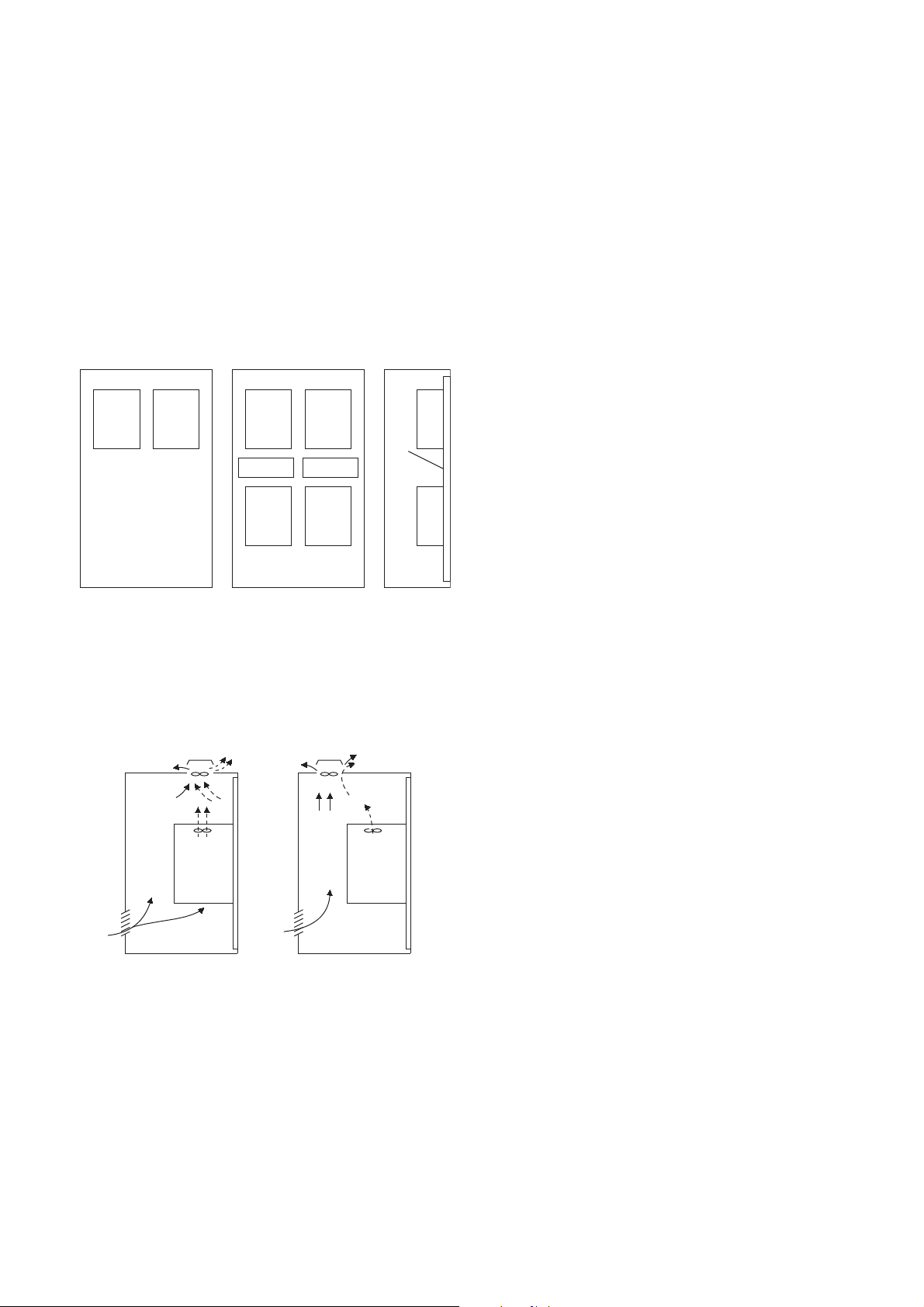
2.3.3 Cooling system types for inverter enclosure
INV
INV
INV
Heat
pipe
From the enclosure that contains the inverter, the heat of the inverter and other equipment (transformers, lamps, resistors, etc.)
and the incoming heat such as direct sunlight must be dissipated to keep the in-enclosure temperature lower than the
permissible temperatures of the in-enclosure equipment including the inverter.
The cooling systems are classified as follows in terms of the cooling calculation method.
• Cooling by natural heat dissipation from the enclosure surface (totally enclosed type)
• Cooling by heat sink (aluminum fin, etc.)
• Cooling by ventilation (forced ventilation type, pipe ventilation type)
• Cooling by heat exchanger or cooler (heat pipe, cooler, etc.)
Cooling system Enclosure structure Comment
Natural
Forced air
Natural ventilation (enclosed
ventilated type)
Natural ventilation (totally
enclosed type)
Heat sink cooling
Forced ventilation
Heat pipe This is a totally enclosed for enclosure downsizing.
Heatsink
INV
INV
This system is low in cost and generally used, but the
enclosure size increases as the inverter capacity
increases. This system is for relatively small capacities.
Being a totally enclosed type, this system is the most
appropriate for hostile environment having dust, dirt, oil
mist, etc. The enclosure size increases depending on
the inverter capacity.
This system has restrictions on the heat sink mounting
position and area. This system is for relatively small
capacities.
This system is for general indoor installation. This is
appropriate for enclosure downsizing and cost
reduction, and often used.
2. INSTALLATION AND WIRING
26
2.3 Installation of the inverter and enclosure design
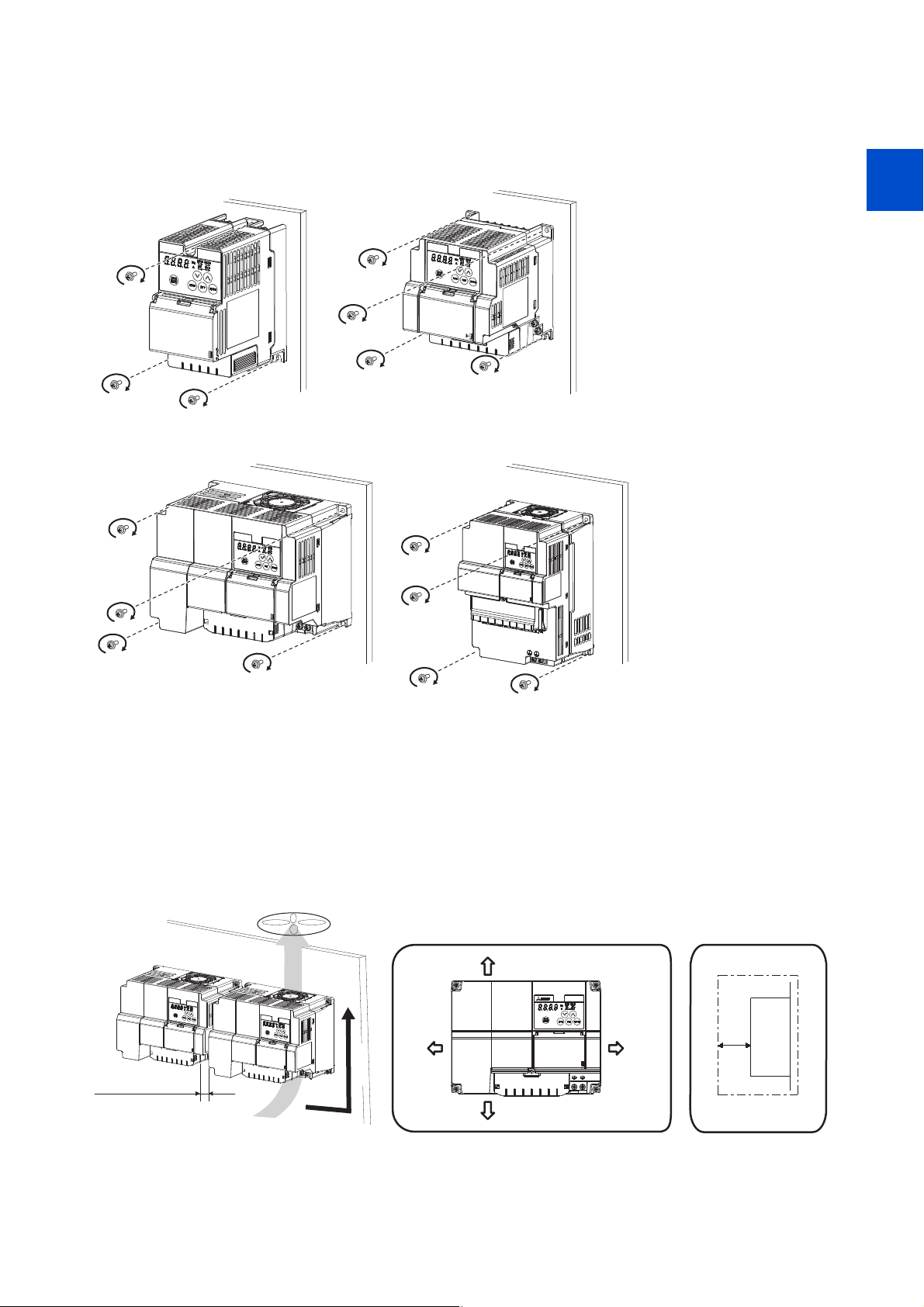
2.3.4 Inverter installation
FR-CS84-120, 160
FR-CS84-036 to 080
FR-CS82S-070, 100
FR-CS84-012, 022
FR-CS82S-025, 042
FR-CS84-230, 295
Clearances (side)Clearances (front)
10 cm or more
1 cm or more
*1*2
1 cm or more
*1*2
10 cm or more
1 cm
or more
*1*2
Inverter
Vertical
Refer to the
clearances below
Inverter placement
1
2
3
5
5
6
7
• Install the inverter on a strong surface securely with screws.
• Leave enough clearances and take cooling measures.
• Avoid places where the inverter is subjected to direct sunlight, high temperature and high humidity.
• Install the inverter on a nonflammable wall surface.
• When encasing multiple inverters in an enclosure, install them in parallel as a cooling measure.
• For heat dissipation and maintenance, keep clearance between the inverter and the other devices or enclosure surface.
The clearance below the inverter is required as a wiring space, and the clearance above the inverter is required as a heat
dissipation space.
• Install the inverter on the wall with no holes to prevent the cooling air from escaping.
8
9
10
*1 FR-CS84-120 or lower, allow 5 cm or more clearance.
*2 When using the inverters at the surrounding air temperature of 40°C or less, the inverters can be installed closely attached (0 cm clearance).
2.3 Installation of the inverter and enclosure design
2. INSTALLATION AND WIRING
27
Installation orientation of the inverter
Inverter Inverter
<Good example> <Bad example>
Install the inverter on a wall as specified. Do not mount it horizontally or in any other way.
Above the inverter
Heat is blown up from inside the inverter by the small fan built in the unit. Any equipment placed above the inverter should be
heat resistant.
Arrangement of multiple inverters
When multiple inverters are placed in the same enclosure, generally arrange them horizontally as shown in the figure (a). When
it is inevitable to arrange them vertically to minimize space, take such measures as to provide guides since heat from the bottom
inverters can increase the temperatures in the top inverters, causing inverter failures.
When mounting multiple inverters, fully take caution not to make the surrounding air temperature of the inverter higher than the
permissible value by providing ventilation and increasing the enclosure size.
InverterInverterInverter Inverter
Guide Guide
Inverter
Enclosure Enclosure
(a) Horizontal arrangement (b) Vertical arrangement
Arrangement of multiple inverters
Inverter
Guide
Arrangement of the ventilation fan and inverter
Heat generated in the inverter is blown up from the bottom of the unit as warm air by the cooling fan. When installing a
ventilation fan for that heat, determine the place of ventilation fan installation after fully considering an air flow. (Air passes
through areas of low resistance. Make an airway and airflow plates to expose the inverter to cool air.)
Arrangementoftheventilationfanandinverter
2. INSTALLATION AND WIRING
28
2.3 Installation of the inverter and enclosure design
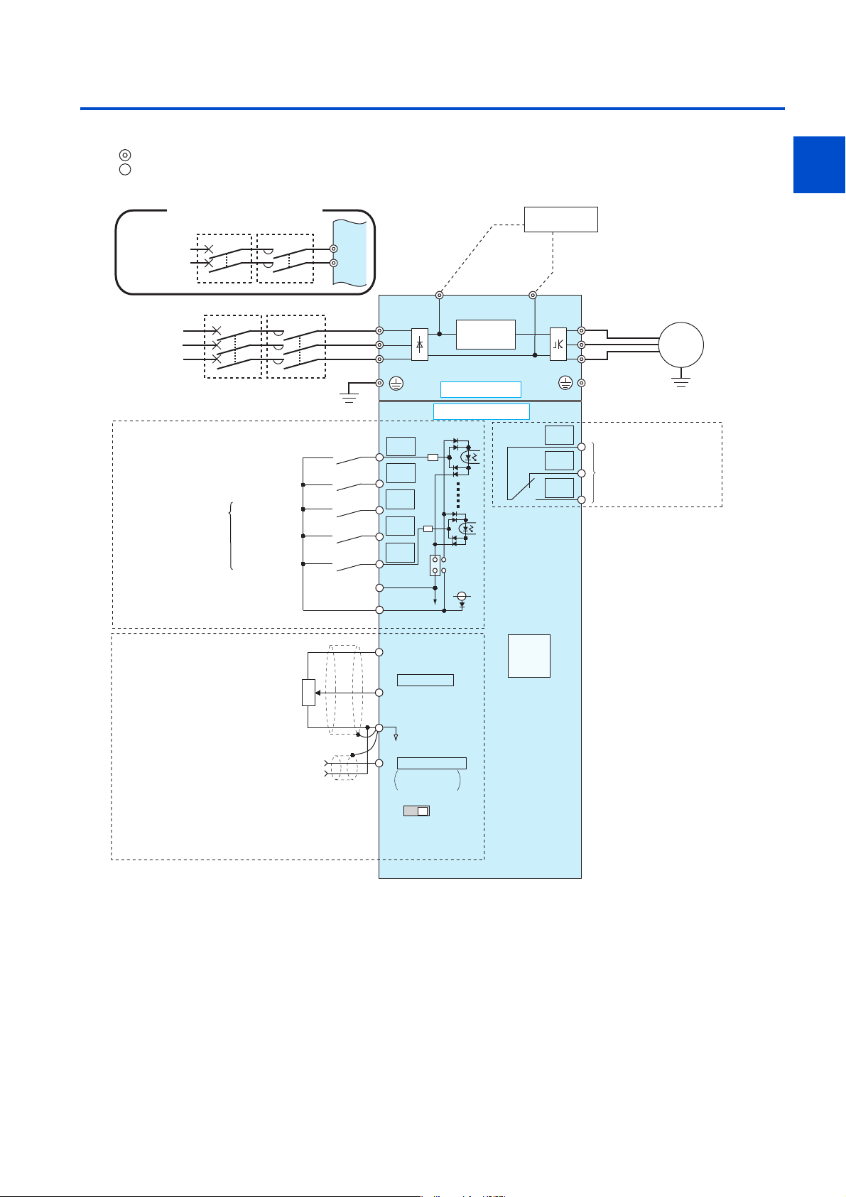
2.4 Terminal connection diagrams
Source logic
Main circuit terminal
Control circuit terminal
1
2
Single-phasepowerinput
MCCB MC
Single-phase
AC power
supply
MCCB MC
Three-phase
AC power
supply
Earth (Ground)
Control input signals
(No voltage input allowed)
Multi-speed
selection
Common for external power
(Common for external power supply transistor)
Frequency setting signals (Analog)
*1 *5
Forward rotation start
Reverse rotation start
High speed
Middle speed
Low speed
supply transistor
24VDC power supply
3
Frequency
setting
potentiometer
1/2W1kΩ
*4
2
1
R/L1
S/L2
P/+
R/L1
S/L2
T/L3
Main circuit
Control circuit
STF
STR
RH
RM
RL
SOURCE
SD
PC
*2
10(+5V)
2 0 to 5 VDC
(0 to 10 VDC)
5(Analog common)
*3
Inrush current
limit circuit
SINK
24V
PU
connector
Brake unit
(Option)
N/-
C
B
A
U
V
W
Relay output
Relay output
(Fault output)
Motor
M
3
5
5
Earth (Ground)
6
7
8
9
10
Terminal 4
input
(Current
input)
(+)
(-)
4 4 to 20 mADC
0 to 5 VDC
0 to 10 VDC
VI
Voltage/current
input switch
*3
*3
2. INSTALLATION AND WIRING
2.4 Terminal connection diagrams
29
 Loading...