

Mitsubishi FR-A540-0.4K-55K, FR-A540-0.4K, FR-A520-0.4K-55K-NA, FR-A540-0.4K-55K-NA, FR-A500 Instruction Manual
...Page 1

Artisan Technology Group is your source for quality
new and certied-used/pre-owned equipment
• FAST SHIPPING AND
DELIVERY
• TENS OF THOUSANDS OF
IN-STOCK ITEMS
• EQUIPMENT DEMOS
• HUNDREDS OF
MANUFACTURERS
SUPPORTED
• LEASING/MONTHLY
RENTALS
• ITAR CERTIFIED
SECURE ASSET SOLUTIONS
SERVICE CENTER REPAIRS
Experienced engineers and technicians on staff
at our full-service, in-house repair center
WE BUY USED EQUIPMENT
Sell your excess, underutilized, and idle used equipment
We also offer credit for buy-backs and trade-ins
www.artisantg.com/WeBuyEquipment
REMOTE INSPECTION
Remotely inspect equipment before purchasing with
our interactive website at www.instraview.com
LOOKING FOR MORE INFORMATION?
Visit us on the web at www.artisantg.com for more
information on price quotations, drivers, technical
specications, manuals, and documentation
Contact us: (888) 88-SOURCE | sales@artisantg.com | www.artisantg.com
SM
View
Instra
Page 2

HIGH FUNCTION
&
LOW ACOUSTIC NOISE
FR-A500
TRANSISTORIZED INVERTER
– INSTRUCTION MANUAL –
FR-A520-0.4K to 55K(-NA)
FR-A540-0.4K to 55K(-NA)(-EC)
Artisan Technology Group - Quality Instrumentation ... Guaranteed | (888) 88-SOURCE | www.artisantg.com
Page 3
A - 1
Thank you for choosing this Mitsubishi transistorized Inverter.
This instruction manual gives handling information and precautions for use of this
equipment.
Incorrect handling might cause an unexpected fault. Before using the inverter, please read
this manual carefully to use the equipment to its optimum.
Please forward this manual to the end user.
This section is specifically about safety matters
Do not attempt to install, operate, maintain or inspect the inverter until you have read through this
instruction manual and appended documents carefully and can use the equipment correctly.
Do not use the inverter until you have a full knowledge of the equipment, safety information and
instructions.
In this instruction manual, the safety instruction levels are classified into “WARNING” and “CAUTION”.
Assumes that incorrect handling may cause hazardous conditions, resulting in
death or severe injury.
Assumes that incorrect handling may cause hazardous conditions, resulting in
medium or slight injury, or may cause physical damage only.
Note that the CAUTION level may lead to a serious consequence according to conditions. Please follow
the instructions of both levels because they are important to personnel safety.
CAUTION
WARNING
Artisan Technology Group - Quality Instrumentation ... Guaranteed | (888) 88-SOURCE | www.artisantg.com
Page 4
A - 2
SAFETY INSTRUCTIONS
1. Electric Shock Prevention
WARNING
z
While power is on or when the inverter is running, do not open the f ront c over. You m ay get an electric
shock.
z
Do not run the inverter with the front cover removed. O therwise, you may access the exposed highvoltage terminals or the charging part of the circuitry and get an electric shock.
z
If power is off, do not remove the f ront cover except f or wiring or periodic inspection. You may access
the charged inverter circuits and get an electric shock.
z
Before starting wiring or inspection, switch power off, wait for more at least 10 minutes and c heck for
the presence of any residual voltage with a meter (check chapter 2 for further details.) etc.
z
Use class 3 (200V) or special class 3 (400V) or higher earthing method to earth the inverter.
z
Any person who is involved in the wiring or inspection of this equipment should be fully competent to do
the work.
z
Always install the inverter before wiring. Otherwise, you may get an electric shock or be injured.
z
Operate the switches with dry hands to prevent an electric shock.
z
Do not subject the cables to scratches, exc ess ive stress , heavy loads or pinching. Otherwise, you may
get an electric shock.
z
Do not change the cooling fan while power is on. To do so will invite a hazardous condition.
2. Fire Prevention
CAUTION
z
Mount the inverter on an incombustible surf ace. Inst alling the inverter dir ectly on or near a combustible
surface could lead to a fire.
z
If the inverter has become faulty, switch off the inverter power. A continuous flow of large curr ent could
cause a fire.
z
Do not connect a resistor directly to the DC terminals P, N. This could cause a fire.
3. Injury Prevention
CAUTION
z
Apply only the voltage specified in the instruction manual to each terminal to prevent damage etc.
z
Ensure that the cables are connected to the correct terminals. Otherwise, damage etc. may occur.
z
Always make sure that polarity is correct to prevent damage etc.
z
After the inverter has been operating for a relativly long period of time, do not touc h the inverter as it
may be hot and you may get burnt.
Artisan Technology Group - Quality Instrumentation ... Guaranteed | (888) 88-SOURCE | www.artisantg.com
Page 5
A - 3
4. Additional instructions
Also note the following points to prevent an accidental failure, injury, electric shock, etc.:
(1) Transportation and installation
CAUTION
z
When carrying products, use correct lifting gear to prevent injury.
z
Do not stack the inverter boxes higher than the number recommended.
z
Ensure that installation position and material can withstand the weight of the inverter. Install
according to the information in the Instruction Manual.
z
Do not operate if the inverter is damaged or has parts missing.
z
Do not hold the inverter by the front cover; it may fall off.
z
Do not stand or rest heavy objects on the inverter.
z
Check the inverter mounting orientation is correct.
z
Prevent screws, wire fragments, conductive bodies, oil or other flamm able substances from entering
the inverter.
z
Do not drop the inverter, or subject it to impact.
z
Use the inverter under the following environmental conditions:
Ambient temperature
Constant torque: -10°C to +50°C (14°F to 122°F) (non-freezing)
(-10°C to +40°C with FR-A5CV attachment)
Variable torque: -10°C to +40°C (14°F to 104°F) (non-freezing)
(-10°C to +30°C with FR-A5CV attachment)
Ambient humidity 90%RH or less (non-condensing)
Storage temperature -20°C to +65°C* (-4°F to 149°F)
Ambience Indoors (free from corrosive gas, flammable gas, oil mist, dust and dirt)
Environment
Altitude, vibration
Maximum 1000m (3280.80 feet.) above sea level for standard operation.
After that derate by 3% for every extra 500m up to 2500m (91%).
••*Temperatures applicable for a short time, e.g. in transit.
(2) Wiring
CAUTION
z
Do not fit capacitive equipment such as a power factor correction capacitor, noise filter or surge
suppressor to the output of the inverter.
z
The connection orientation of the output cables U, V, W to the motor will affect the direction of
rotation of the motor.
(3) Trial run
CAUTION
z
Check all parameters, and ensure that the machine will not be damaged by a sudden start-up.
(4) Operation
CAUTION
z
When you have chosen the retry function, stay away from the equipm ent as it will restart s uddenly
after an alarm stop.
z
The [STOP] key is valid only when the appropriate function setting has been made. Prepare an
emergency stop switch separately.
z
Make sure that the start signal is off bef ore r es etting the inverter alarm. A failure to do so may restart
the motor suddenly.
Artisan Technology Group - Quality Instrumentation ... Guaranteed | (888) 88-SOURCE | www.artisantg.com
Page 6
A - 4
CAUTION
z
The load used should be a three-phase induction motor only. Connection of any other electrical
equipment to the inverter output may damage the equipment.
z
The electronic overcurrent protection does not guarantee protection of the motor from overheating.
z
Do not use a magnetic contactor on the inverter input for frequent starting/stopping of the inverter.
z
Use a noise filter to reduce the effect of electromagnetic interference. Otherwise nearby electronic
equipment may be affected.
z
Take measures to suppress harmonics. Otherwise power harmonics from the inverter may
heat/damage the power capacitor and generator.
z
When a 400V class motor is inverter-driven, it should be insulation-enhanced or surge voltages
suppressed. Surge voltages attributable to the wiring constants may occur at the motor terminals,
deteriorating the insulation of the motor.
z
When parameter clear or all clear is per form ed, eac h param eter r eturns to the f actory setting. Re-set
the required parameters before starting operation.
z
The inverter can be easily set for high-speed operation. Before changing its setting, examine the
performance of the motor and machine.
z
In addition to the inverter's holding function, install a holding device to ensure safety.
z
Before running an inverter which had been stored for a long period, always perform inspection and
test operation.
(5) Emergency stop
CAUTION
z
Provide a safety backup such as an emergency brake which will prevent the machine and equipment
from hazardous conditions if the inverter fails.
(6) Maintenance, inspection and parts replacement
CAUTION
z
Do not carry out a megger (insulation resistance) test on the control circuit of the inverter.
(7) Disposing of the inverter
CAUTION
z
Treat as industrial waste.
(8) General instructions
Many of the diagrams and drawings in this instruction manual show the inverter without a cover, or partially
open. Never run the inverter like this. Always replace the cover and follow this instr uction manual when
operating the inverter.
Artisan Technology Group - Quality Instrumentation ... Guaranteed | (888) 88-SOURCE | www.artisantg.com
Page 7

CONTENTS
I
287/,1(
1.1 Pre-Operation Information.........................................................................................................................................1
1.1.1 Precautions for operation....................................................................................................................................1
1.2 Basic Configuration....................................................................................................................................................2
1.2.1 Basic configuration .............................................................................................................................................2
1.3 Structure....................................................................................................................................................................3
1.3.1 Appearance and structure ..................................................................................................................................3
1.3.2 Removal and reinstallation of the front cover .....................................................................................................4
1.3.3 Removal and reinstallation of the operation panel..............................................................................................6
,167$//$7,21 $1' :,5,1*
2.1 Installation..................................................................................................................................................................7
2.1.1 Instructions for installation..................................................................................................................................7
2.2 Wiring ........................................................................................................................................................................9
2.2.1 Terminal connection diagram .............................................................................................................................9
2.2.2 Wiring of the main circuit ..................................................................................................................................12
2.2.3 Wiring of the control circuit ...............................................................................................................................18
2.2.4 Connection to the PU connector.......................................................................................................................22
2.2.5 Connection of stand-alone option units ............................................................................................................24
2.2.6 Design information............................................................................................................................................28
2.3 Other wiring .............................................................................................................................................................29
2.3.1 Power harmonics..............................................................................................................................................29
2.3.2 Japanese harmonic suppression guidelines.....................................................................................................30
2.3.3 Inverter-generated noises and reduction techniques........................................................................................33
2.3.4 Leakage currents and countermeasures..........................................................................................................37
2.3.5 Inverter-driven 400V class motor......................................................................................................................38
2.3.6 Peripheral devices............................................................................................................................................39
2.3.7 Instructions for compliance with the UL and CSA standards............................................................................41
2.3.8 Instructions for compliance with the European standards................................................................................42
2.3.9 Earthing (EC version)........................................................................................................................................43
23(5$7,21
3.1 Pre-Operation Information.......................................................................................................................................45
3.1.1 Devices and parts to be prepared for operation ...............................................................................................45
3.1.2 Power on...........................................................................................................................................................47
3.1.3 Parameter check...............................................................................................................................................47
3.2 Operation.................................................................................................................................................................53
3.2.1 Pre-operation checks........................................................................................................................................53
3.2.2 External operation mode (Operation using external input signals)...................................................................54
3.2.3 PU operation mode (Operation using the operation panel (FR-DU04))...........................................................55
3.2.4 Combined operation mode (Operation using the external input signals and PU)............................................56
3$5$0(7(5
4.1 Parameter List .........................................................................................................................................................57
4.2 Parameter Function Details.....................................................................................................................................63
z
Torque boost (Pr. 0, Pr. 46, Pr. 112).......................................................................................................................63
z
Output frequency range (Pr. 1, Pr. 2, Pr. 18) ..........................................................................................................64
Artisan Technology Group - Quality Instrumentation ... Guaranteed | (888) 88-SOURCE | www.artisantg.com
Page 8
II
z
Base frequency, base frequency voltage (Pr. 3, Pr. 19, Pr. 47, Pr. 113).................................................................65
z
Multi-speed operation (Pr. 4 to Pr. 6, Pr. 24 to Pr. 27, Pr. 232 to Pr. 239)..............................................................66
z
Acceleration/deceleration time (Pr. 7, Pr. 8, Pr. 20, Pr. 21, Pr. 44, Pr. 45, Pr. 110, Pr. 111)..................................67
z
Electronic overcurrent protection (Pr. 9)..................................................................................................................68
z
DC dynamic brake (Pr. 10, Pr. 11, Pr. 12)...............................................................................................................69
z
Starting frequency (Pr. 13)......................................................................................................................................70
z
Load pattern selection (Pr. 14)................................................................................................................................70
z
Jog operation (Pr. 15, Pr. 16)..................................................................................................................................71
z
MRS input selection (Pr. 17) ...................................................................................................................................72
z
Stall prevention (Pr. 22, Pr. 23, Pr. 66, Pr. 148, Pr. 149, Pr. 154)...........................................................................73
z
Multi-speed input compensation (Pr. 28).................................................................................................................74
z
Acceleration/deceleration pattern (Pr. 29, Pr. 140 to Pr. 143).................................................................................75
z
Regenerative brake duty (Pr. 30, Pr. 70).................................................................................................................76
z
Frequency jump (Pr. 31 to Pr. 36)...........................................................................................................................77
z
Speed display (Pr. 37, Pr. 144)............................................................................................................................... 78
z
Up-to-frequency sensitivity (Pr. 41).........................................................................................................................79
z
Output frequency detection (Pr. 42, Pr. 43, Pr. 50, Pr. 116) ...................................................................................79
z
Second/third stall prevention (Pr. 48, Pr. 49, Pr. 114, Pr. 115)...............................................................................80
z
Monitor display/FM, AM terminal function selection (Pr. 52 to Pr. 54, Pr. 158).......................................................82
z
Monitoring reference (Pr. 55, Pr. 56).......................................................................................................................84
z
Automatic restart after instantaneous power failure (Pr. 57, Pr. 58, Pr. 162 to Pr. 165).........................................85
z
Remote setting function selection (Pr. 59) ..............................................................................................................87
z
Intelligent mode selection (Pr. 60)...........................................................................................................................88
z
Acceleration/deceleration reference current/lift mode starting frequency (Pr. 61 to Pr. 64)....................................90
z
Retry function (Pr. 65, Pr. 67 to Pr. 69)...................................................................................................................91
z
Applied motor (Pr. 71).............................................................................................................................................93
z
PWM carrier frequency (Pr. 72, Pr. 240).................................................................................................................94
z
Voltage input (Pr. 73) ..............................................................................................................................................95
z
Input filter time constant (Pr. 74).............................................................................................................................96
z
Reset selection/PU disconnection detection/PU stop selection (Pr. 75).................................................................96
z
Alarm code output selection (Pr. 76).......................................................................................................................98
z
Parameter write inhibit selection (Pr. 77) ................................................................................................................99
z
Reverse rotation prevention selection (Pr. 78)......................................................................................................100
z
Operation mode selection (Pr. 79) ........................................................................................................................101
z
Motor capacity/number of motor poles/speed control gain (Pr. 80, Pr. 81, Pr. 89) ...............................................104
z
Offline auto tuning function (Pr. 82 to Pr. 84, Pr. 90 to Pr. 94, Pr. 96)..................................................................105
z
Online auto tuning selection (Pr. 95).....................................................................................................................111
z
V/F control frequency (voltage) (Pr. 100 to Pr. 109)..............................................................................................113
z
Computer link operation (Pr. 117 to Pr. 124).........................................................................................................114
z
PID control (Pr. 128 to Pr. 134).............................................................................................................................124
z
Commercial power supply-inverter switch-over function (Pr. 135 to Pr. 139)........................................................131
z
Output current detection function (Pr. 150, Pr. 151)..............................................................................................135
z
Zero current detection (Pr. 152, Pr. 153)...............................................................................................................136
z
RT signal activated condition selection (Pr. 155)..................................................................................................137
z
Stall prevention function and current limit function (Pr. 156).................................................................................137
z
OL signal output timer (Pr. 157)............................................................................................................................ 139
z
User group selection (Pr. 160, Pr. 173 to Pr. 176)................................................................................................140
z
Watt-hour meter clear/actual operation hour meter clear (Pr. 170, Pr. 171).........................................................141
z
Input terminal function selection (Pr. 180 to Pr. 186)............................................................................................141
z
Output terminal function selection (Pr. 190 to Pr. 195) .........................................................................................144
Artisan Technology Group - Quality Instrumentation ... Guaranteed | (888) 88-SOURCE | www.artisantg.com
Page 9
III
z
User initial value setting (Pr. 199) .........................................................................................................................146
z
Programmed operation function (Pr. 200 to Pr. 231) ............................................................................................147
z
Cooling fan operation selection (Pr. 244)..............................................................................................................151
z
Stop selection (Pr. 250).........................................................................................................................................152
z
Power failure-time deceleration-to-stop function (Pr. 261 to Pr. 266) ...................................................................154
z
Stop-on-contact, load torque high-speed frequency selection (Pr. 270)...............................................................156
z
High-speed frequency control (Pr. 271 to Pr. 274)................................................................................................157
z
Stop on contact (Pr. 275, Pr. 276).........................................................................................................................161
z
Brake sequence function (Pr. 278 to Pr. 285).......................................................................................................164
z
Droop control (Pr. 286, Pr. 287)............................................................................................................................ 168
z
Meter (frequency meter) calibration (Pr. 900, Pr. 901)..........................................................................................169
z
Frequency setting voltage (current) bias and gain (Pr. 902 to Pr. 905).................................................................171
z
Buzzer control (Pr. 990) ........................................................................................................................................173
3527(&7,9( )81&7,216
5.1 Errors (alarms).......................................................................................................................................................174
5.1.1 Error (alarm) definitions..................................................................................................................................174
5.1.2 Correspondences between digital and actual characters...............................................................................177
5.1.3 Alarm code output...........................................................................................................................................178
5.1.4 Resetting the inverter......................................................................................................................................178
5.2 Troubleshooting.....................................................................................................................................................179
5.2.1 Checking the operation panel display at alarm stop.......................................................................................179
5.2.2 Faults and check points..................................................................................................................................180
5.3 Precautions for Maintenance and Inspection.........................................................................................................182
5.3.1 Precautions for maintenance and inspection..................................................................................................182
5.3.2 Check items....................................................................................................................................................182
5.3.3 Periodic inspection..........................................................................................................................................182
5.3.4 Insulation resistance test using megger .........................................................................................................183
5.3.5 Pressure test...................................................................................................................................................183
5.3.6 Replacement of parts......................................................................................................................................186
5.3.7 Inverter replacement.......................................................................................................................................187
5.3.8 Measurement of main circuit voltages, currents and power............................................................................188
63(&,),&$7,216
6.1 Standard Specifications.........................................................................................................................................190
6.1.1 Model specifications .......................................................................................................................................190
6.1.2 Common specifications...................................................................................................................................192
6.1.3 Outline drawings.............................................................................................................................................194
237,216
7.1 Option List..............................................................................................................................................................198
7.1.1 Stand-alone options........................................................................................................................................198
7.1.2 Inboard dedicated options ..............................................................................................................................200
$33(1',&(6
Appendix 1 Data Code List..........................................................................................................................................201
Appendix 2 List of Parameters Classified by Purposes of Use....................................................................................207
Appendix 3 Operating the Inverter Using a Single-Phase Power Supply....................................................................208
Artisan Technology Group - Quality Instrumentation ... Guaranteed | (888) 88-SOURCE | www.artisantg.com
Page 10

1
CHAPTER 1
OUTLINE
This chapter gives information on the basic "outline" of this
product.
Always read the instructions in this chapter before using the
equipment.
1.1 Pre-Operation Information........................................1
1.2 Basic Configuration..................................................2
1.3 Structure..................................................................3
<Abbreviations>
y
DU
Operation panel (FR-DU04)
y
PU
Operation panel (FR-DU04) and parameter unit (FR-PU04)
y
Inverter
Mitsubishi transistorized inverter FR-A500 series
y
Pr.
Parameter number
y
PU operation
Operation using the PU (FR-DU04/FR-PU04)
y
External operation
Operation using the control circuit signals
y
Combined operation
Operation using both the PU (FR-DU04/FR-PU04) and
external operation
y
FR-A200E
Mitsubishi transistorized inverter FR-A200 series
<EXCELLENT> series
CHAPTER 1 OUTLINE
CHAPTER 2 INSTALLATION AND WIRING
CHAPTER 3 OPERATION
CHAPTER 4 PARAMETERS
CHAPTER 5 PROTECTIVE FUNCTIONS
CHAPTER 6 SPECIFICATIONS
CHAPTER 7 OPTIONS
APPENDICES
Artisan Technology Group - Quality Instrumentation ... Guaranteed | (888) 88-SOURCE | www.artisantg.com
Page 11
1.1 Pre-Operation Information
OUTLINE
1
1 OUTLINE
1.1 Pre-Operation Information
1.1.1 Precautions for operation
Incorrect handling might cause the inverter to operate improperly, its life to be reduced considerably, or at the
worst, the inverter to be damaged. Handle the inverter properly in accordance with the information in each
section as well as the precautions and instructions of this manual to use it correctly.
This manual is written for the FR-A500 series transistorized inverters.
For handling information on the parameter unit ( FR- PU04), inboar d options , stand- alone options , etc ., ref er to
the corresponding manuals.
(1)
Unpacking and product check
Unpack the inverter and check the capacity plate on the front cover and the rating plate on the inverter side
face to ensure that the product agrees with your order and the inverter is intact.
1) Inverter type
FR-A520-0.4K/
MITSUBISHI
MODEL
FR-A520-0.4K
INVERTER
POWER
INPUT
OUTPUT
SERIAL
MITSUBISHI ELECTRIC CORPORATION
0.4kW
XXXXX
MADE IN JAPAN
XXXXX
Capacity plate
Inverter type Serial number
Capacity plate
Rating plate
Rating plate
Input rating
Output rating
Serial number
Inverter type
FR- A520 - 0.4K -
Symbol Voltage Class
A520
A540
200V class
400V class
Symbol Applicable Motor Capacity
0.4K to 55K Indicates capacity in "kW".
Symbol Specifications
NoneNAJapanese specifications
U.S. specifications
EC European specifications
Applicable moto
r
capacity
2) Accessory
Instruction manual
If you have found any discrepancy, damage, etc., please contact your sales representative.
(2)
Preparations of instruments and parts required for operation
Instruments and parts to be prepared depend on how the inverter is operated. Prepare equipment and parts
as necessary. (Refer to page 45.)
(3)
Installation
To operate the inverter with high performance f or a long time, install the inverter in a proper place, in the
correct direction, and with proper clearances. (Refer to page 7.)
(4)
Wiring
Connect the power supply, motor and operation signals (control signals) to the terminal block. Note that
incorrect connection may damage the inverter and peripheral devices. (See page 12.)
Artisan Technology Group - Quality Instrumentation ... Guaranteed | (888) 88-SOURCE | www.artisantg.com
Page 12
1.2 Basic Configuration
OUTLINE
2
1.2 Basic Configuration
1.2.1 Basic configuration
The following devices are required to operate the inverter. Pr oper peripheral devices must be selected and
correct connections made to ensure proper operation. Inc orrect system configuration and connections can
cause the inverter to operate improperly, its life to be reduced considerably, and in the worst case, the
inverter to be damaged.
Please handle the inverter properly in accordance with the information in each section as well as the
precautions and instructions of this manual. (For connections of the peripheral devices, refer to the
corresponding manuals.)
Name Description
Power supply
Use the power supply within the perm is si ble
power supply specifications of the in verter.
(Refer to page 39.)
Earth leakage
circuit breaker
(ELB) or no-fuse
breaker (NFB)
The breaker should be selected with care
since a large inrush current flows in the
inverter at power on. (Refer to page 39.)
Magnetic
contactor
The magnetic contactor need not be
provided. When installed, do not us e it to
start or stop the inverter. It might reduce the
inverter life.
(Refer to page 39.)
Reactors
The reactors must be used when t he power
factor is to be improved or the inverter is
installed near a large power supply system
(1000KVA or more and wiring distance
within 10m (32.81 feet)). Make selection
carefully.
Inverter
z
The inverter life is influenced by ambient
temperature. The ambient temperature
should be as low as possible within the
permissible range.
This must be noted especiall y when the
inverter is installed in an enclosure.
(Refer to page 7.)
z
Incorrect wiring might lead to inverter
damage. The control signal lines should
be kept away from the main circuit to
protect them from nois e. (Refer to page
9.)
Devices
connected to the
output
Do not connect a power capacitor, surge
suppressor or radio noise filter to the output
side.
(MC)
Ground
DC reactor
(FR-BEL)
Ground
(NFB)
or
(ELB)
AC reactor
(FR-BAL)
Ground
To prevent an electric shock, always ground
the motor and inverter.
Japanese Harmonic Suppression Guideline
The "harmonic suppression guideline for household appliances and general-purpose products" was issued
by the Ministry of International Trade and Industry in September, 1994. This
g
uideline applies to the
FR-A520-0.4K to 3.7K. By connection of the power factor im provin
g
reactor (FR-BEL or FR-BAL), this
product conforms to the "harm onic suppr ession technique f or transistor ized inverters (input c urrent 20A or
less)" set forth by the Japan Electrical Manufactures' Association.
Artisan Technology Group - Quality Instrumentation ... Guaranteed | (888) 88-SOURCE | www.artisantg.com
Page 13
1.3 Structure
OUTLINE
3
1.3 Structure
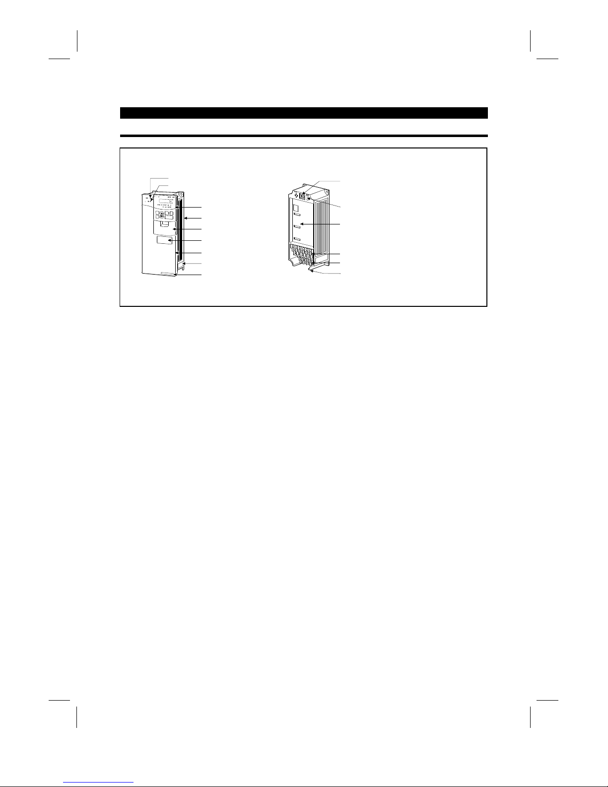
1.3.1 Appearance and structure
(1) Front view (2) Without front cover
POWER lamp
ALARM lamp
Operation panel (FR-DU04)
Brake resistor* (Fitted to the back)
Accessory cover
Wiring port cover for option
Front cover
Rating plate
Capacity plate
Wiring cover
PU connector
(Provided with modular jack type relay connector)
(For use of RS-485 cable)
Modular jack type relay connector compartment
Inboard option mounting position
Control circuit terminal block
Main circuit terminal block
*7.5K or less inverters are equipped with an inboard brake resistor.
Note: The "EC" version of the FR-A500 uses pheonix type connectors f or the control circuit terminal
block.
Artisan Technology Group - Quality Instrumentation ... Guaranteed | (888) 88-SOURCE | www.artisantg.com
Page 14
OUTLINE
4
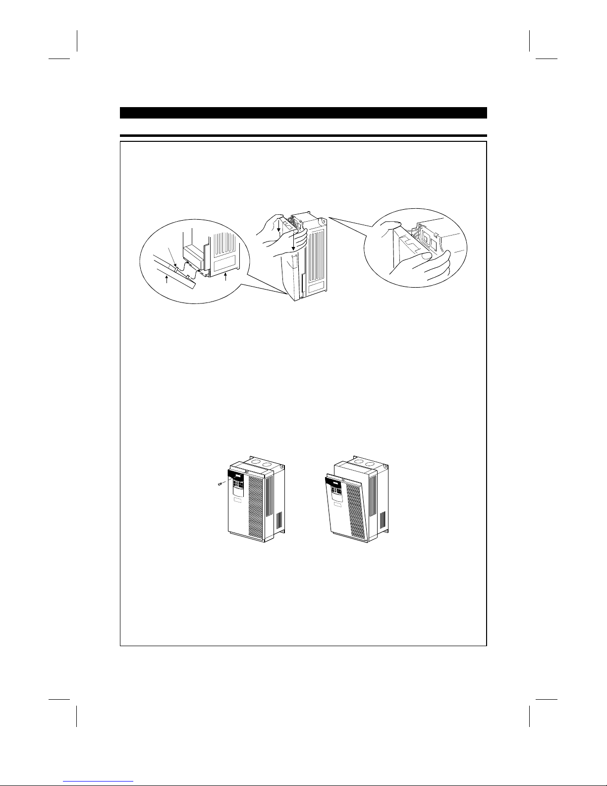
1.3.2 Removal and reinstallation of the front cover
FR-A520-0.4K to 11K, FR-A540-0.4K to 7.5K
•
Removal
1) Hold both sides of the front cover top and push the front cover down.
2) Hold down the front cover and pull it toward you to remove.
(The front cover may be removed with the PU (FR-DU04/FR-PU04) on.)
Front cover
Inverter
Catch
•
Reinstallation
1) Insert the catches at the bottom of the front cover into the sockets of the inverter.
2) Using the catches as supports, securely press the front cover against the inverter.
Note: When the operation panel is mounted and the front c over is removed, remove the operation
panel before reinstalling the front cover.
FR-A520-15K to 22K, FR-A540-11K to 22K
•
Removal
1) Remove the installation screw at top of the front cover.
2) Hold both ends of the front cover top.
3) Pull the front cover toward you to remove.
(The front cover may be removed with the PU (FR-DU04/FR-PU04) on.)
•
Reinstallation
1) Insert the catches at the front cover bottom into the sockets of the inverter.
2) Using the catches as supports, securely press the front cover against the inverter.
3) Fix the front cover with the top screw.
Note: When the operation panel is m ounted on the front cover removed, rem ove the operation panel
before reinstalling the front cover.
Artisan Technology Group - Quality Instrumentation ... Guaranteed | (888) 88-SOURCE | www.artisantg.com
Page 15
OUTLINE
5
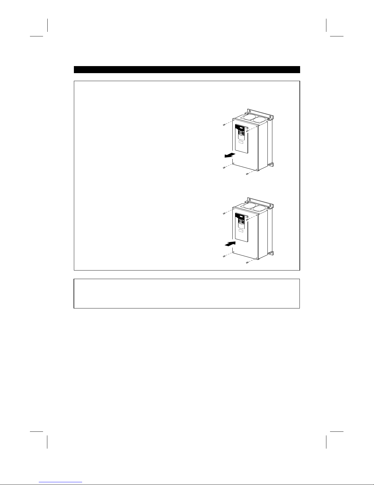
FR-A520-30K to 55K, FR-A540-30K to 55K
•
Removal
1) Remove the front cover mounting screws.
•
Reinstallation
1) Fix the front cover with the mounting screws.
Note: 1. Make sure that the front cover has been reinstalled securely.
2. The sam e ser ial number is printed on the capacity plate of the front c over and the r ating plate of
the inverter. Before reinstalling the front cover, c heck the serial number to ensure that the cover
removed is reinstalled to the inverter from where it was removed.
Artisan Technology Group - Quality Instrumentation ... Guaranteed | (888) 88-SOURCE | www.artisantg.com
Page 16
OUTLINE
6
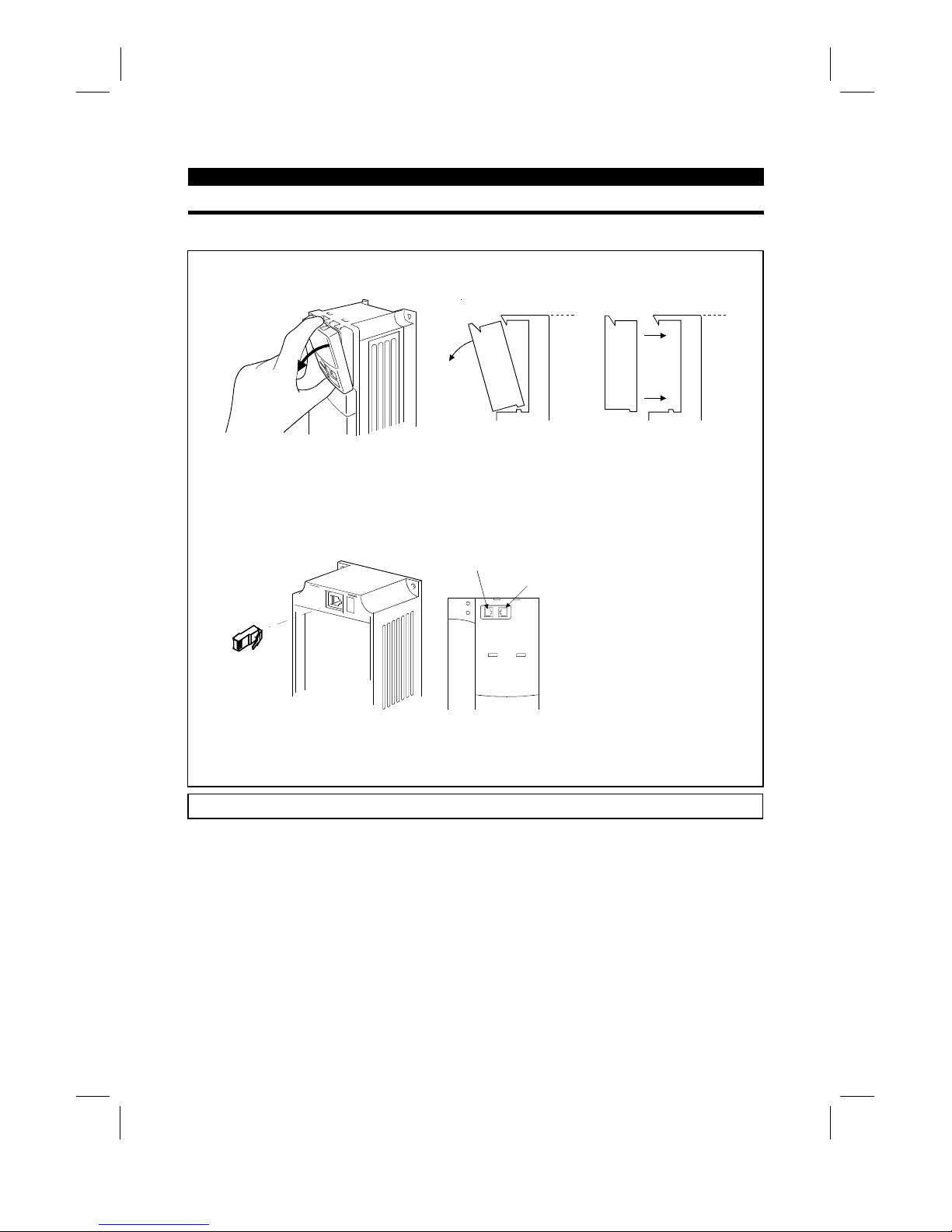
1.3.3 Removal and reinstallation of the operation panel
To ensure safety, remove and reinstall the operation panel after switching power off.
•
Removal
Hold down the top button of the operation panel and pull the operation panel toward you to remove.
Removal
Reinstallation
To reinstall, insert straight and mount securely.
•
Reinstallation using the connection cable
1) Remove the operation panel.
2) Disconnect the modular jack type relay connector. (Place the disconnec ted m odular j ack type relay
connector in the modular jack type relay connector compartment.)
Modular jack type relay connector compartment
Modular jack type relay connector
3) Securely plug one end of the connection cable into the PU connector (m odular jack type relay
connector) of the inverter and the other end into the operation panel.
Note: Install the operation panel only when the front cover is on the inverter.
Artisan Technology Group - Quality Instrumentation ... Guaranteed | (888) 88-SOURCE | www.artisantg.com
Page 17

2
CHAPTER 2
INSTALLATION AND WIRING
This chapter gives information on the basic "installation and
wiring" of this product.
Always read the instructions in this chapter before using the
equipment.
2.1 Installation................................................................ 7
2.2 Wiring ...................................................................... 9
2.3 Other wiring .............................................................29
CHAPTER 1 OUTLINE
CHAPTER 2 INSTALLATION AND WIRING
CHAPTER 3 OPERATION
CHAPTER 4 PARAMETERS
CHAPTER 5 PROTECTIVE FUNCTIONS
CHAPTER 6 SPECIFICATIONS
CHAPTER 7 OPTIONS
APPENDICES
Artisan Technology Group - Quality Instrumentation ... Guaranteed | (888) 88-SOURCE | www.artisantg.com
Page 18
2.1 Installation
INSTALLATION AND WIRING
7
2 INSTALLATION AND WIRING
2.1 Installation
2.1.1 Instructions for installation
1) Handle the unit carefully.
The inverter uses plastic parts. Handle it gently to protect it from damage. Also, hold the unit with even
strength and do not apply too much strength to the front cover alone.
2) Install the inverter in a place where it is immune to vibration. (5.9 m/s
2
{0.6G} or less)
Also note the cart, press, etc.
3) Note on ambient temperature
The inverter life is under great influence of ambient temperature. In the place of installation, ambient
temperature must be within the permissible range (depending upon the operation mode and conditions
(see ambient temperature specifications on page 190). Check that the ambient temperature is within that
range in the positions shown in figure 3).
4) Install the inverter on a non-combustible surface.
The inverter will be very hot (maximum about 150°C). Install it on a non-combustible surface (e.g. metal).
Also leave sufficient clearances around the inverter.
5) Avoid high temperature and high humidity.
Avoid places where the inverter is subjected to direct sunlight, high temperature and high humidity.
6) The amount of heat generated in an enclosure can be reduced c onsiderably by placing the heat sink
outside the enclosure.
Note: 1. Use the option (FR-A5CN
) for installation. The mounting area should be cut to the panel
cutting dimensions.
2. The cooling section outside the enclosure has the cooling fan. Do not use the inverter in any
environment where it is exposed to waterdrops, oil mist, dust, etc.
7) Avoid places where the inverter is exposed to oil mist, flammable gases, fluff, dust, dirt etc.
Install the inverter in a clean place or inside a "totally enclosed" panel which does not accept any
suspended matter.
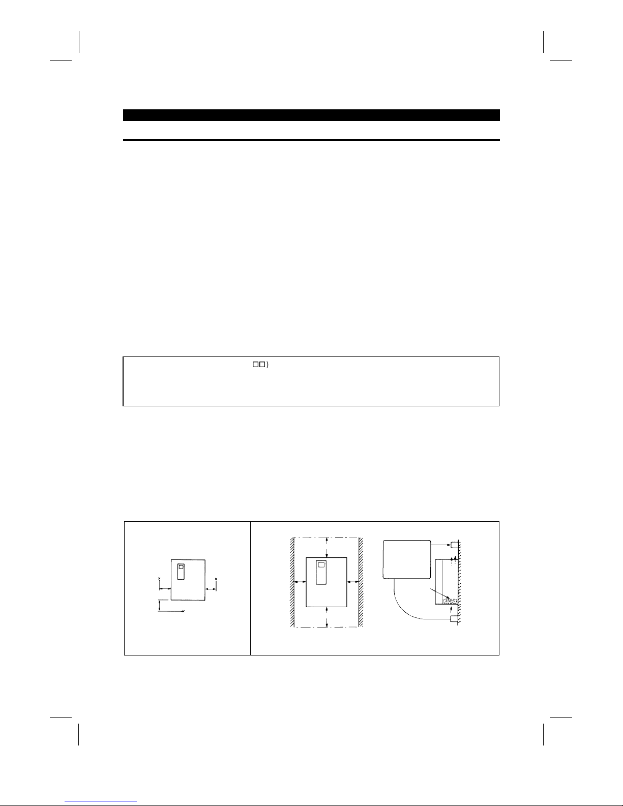
8) Note the cooling method when the inverter is installed in an enclosure.
When two or more inverters are installed or a ventilation fan is mounted in an enclosure, the inverters and
ventilation fan must be installed in proper positions with extreme care taken to keep the ambient
temperatures of the inverters below the permissible value. If they are installed in improper positions, the
ambient temperatures of the inverters will rise and ventilation effect will be reduced.
9) Install the inverter securely with screws or bolts in the vertical direction.
3) Note on ambient temperature
Measurement
position
Measurement
position
5cm
(1.97 inches)
5cm
(1.97 inches)
5cm
(1.97 inches)
4) Clearances around the inverter
10cm (3.94 inches)
5cm (1.97 inches)
or more *
*: 1cm (0.39 inches) or more for model 3.7K or less
Leave sufficient
clearances above
and under the
inverter to ensure
adequate ventilation.
Cooling fan built
in the inverter
Cooling air
5cm (1.97 inches)
or more *
or more
10cm (3.94 inches)
or more
Artisan Technology Group - Quality Instrumentation ... Guaranteed | (888) 88-SOURCE | www.artisantg.com
Page 19

INSTALLATION AND WIRING
8
8) For installation in an enclosure
Ventilation fan
(Correct example)
Position of Ventilat ion Fan
Inveter Inveter
Inveter
(Correct example) (Incorrect example)
Built-in cooling fan
Inveter
Inveter
Inveter
Accommodation of two or more inv erters
(Incorrect example)
9) Vertical mounting
(1)
Wiring cover and handling (22K or less
)
1) When cable conduits are not connected
Cut the protective bushes of the wiring cover with nippers or a cutter before running the cables.
Wiring cover
Protective bush
WARNING
Do not remove the protective bushes. Otherwise, the cable sheathes may be scratched by the wiring cover
edges, resulting in a short circuit or ground fault.
2) When cable conduits are connected
Remove the corresponding protective bushes and connect the cable conduits.
Artisan Technology Group - Quality Instrumentation ... Guaranteed | (888) 88-SOURCE | www.artisantg.com
Page 20
2.2 Wiring
INSTALLATION AND WIRING
9
2.2 Wiring
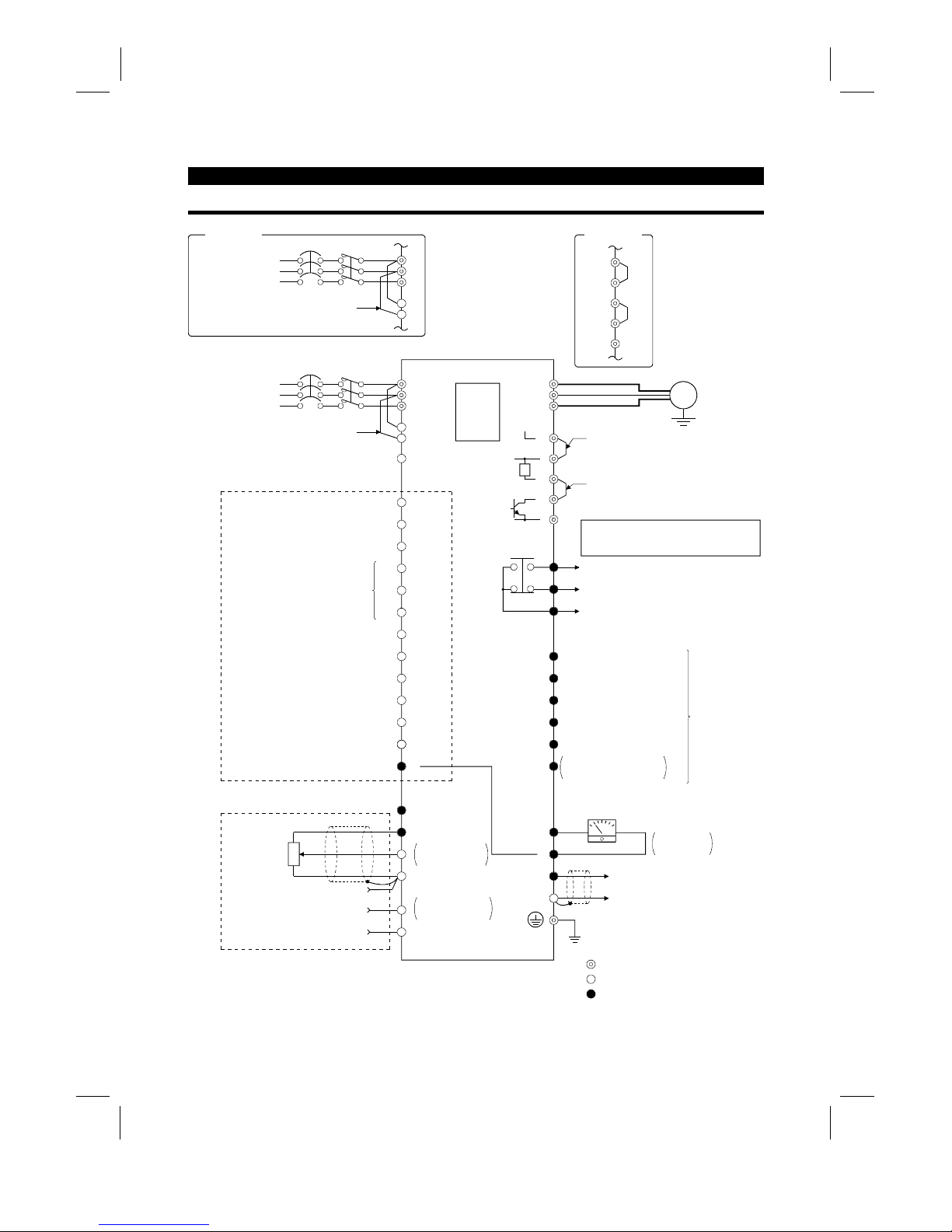
2.2.1 Terminal connection diagram
NFB
R
S
T
R1
S1
PC
STF
STR
STOP
RH
RM
RL
JOG
RT
MRS
RES
AU
CS
SD
10E(+10V)
10(+5V)
2
5
2
3
1
1
4 (4 to 20mADC)
Frequency setting
potentiometer
1/2W1k
Ω
RUN
SU
IPF
OL
FU
SE
FM
SD
IM
A
B
C
U
V
W
P1
P
PX
PR
N
+−
(
−
)
(
+
)
AM
5
R
Ground
Main circuit terminal
Control circuit input terminal
Control circuit output terminal
3-phase AC power supply
Jumper
24VDC power output and external transistor common
(Contact input common for source logic)
Forward rotation start
Reverse rotation start
Start self-holding selection
High
Middle
Low
Jog mode
Second acceleration/deceleration time selection
Output stop
Reset
Current input selection
Selection of automatic restart
after instantaneous power failure
(Contact input common for sink logic)
Control input signals (no voltage input allowed)
Frequency setting signals (analog)
Common
Auxiliary input
Current input
0 to 5VDC
0 to 10VDC
Selected
(Analog common)
0 to ± 5VDC
0 to ±10VDC
Selected
PU
connector
(Note)
(Note)
Motor
Ground
Jumper
Remove this jumper when using FR-BEL.
Jumper
Remove this jumper when using FR-ABR.
Note: Terminals PR, PX are provided for
FR-A520-0.4K to 7.5K.
FR-A540-0.4K to 7.5K
Alarm detection
Running
Up to frequency
Instantaneous power failure
Overload
Frequency detection
Open collector output common
Common to sink and source
Open collector
outputs
Meter
(e.g. frequency meter)
Moving-coil type
1mA full-scale
Analog signal output
(0 to 10VDC)
Multi-speed selection
(RS-485)
NFB
L
1
L
2
L
3
L
11
L
21
3-phase AC power supply
Jumper
EC version
P1
+
PX
PR
–
EC version
Artisan Technology Group - Quality Instrumentation ... Guaranteed | (888) 88-SOURCE | www.artisantg.com
Page 21
INSTALLATION AND WIRING
10
(1)
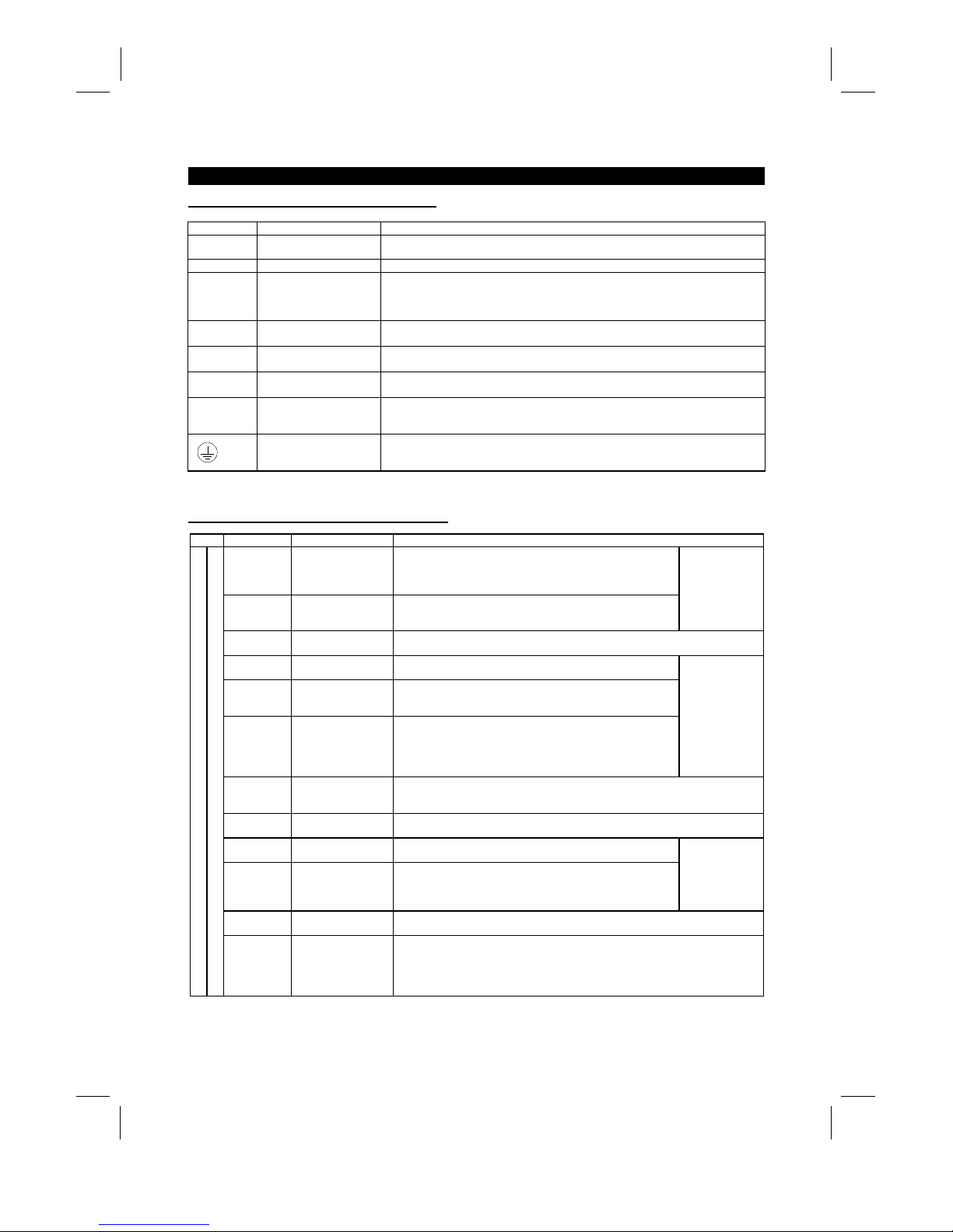
Description of main circuit terminals
Symbol Terminal Name Description
R, S, T
〈
L
1
, L2, L
3
〉
AC power input
Connect to the commerci al power supply. Keep these t erminals unconnected when
using the high power factor converter (FR-HC).
U, V, W Inverter output Connect a three-phase squirrel-cage motor.
R1, S1
〈
L
11
, L
21
〉
Power supply for control
circuit
Connected to the AC power supply terminals R and S 〈L
1
and L
2
〉
. To retain the alarm
display and alarm output or when using the high power factor converter (FR-HC),
remove the jumpers from terminals R-R1 and S-S1 〈L
1
-
L11 and L
2
-
L
21
〉
and apply
external power to these terminals.
P, PR
〈+
, PR
〉
Brake resistor connection
Disconnect the jumper from terminals PR-PX and connect the optional brak e resistor
(FR-ABR) across terminal s P-PR.
P, N
〈+, −〉
Brake unit connection
Connect the optional FR-BU brake unit, power return convert er (FR-RC) or high power
factor converter (FR-HC).
P, P1
〈+
, P1
〉
Power factor improving
DC reactor connection
Disconnect the jumper from terminals P-P1
〈+
-P1〉 and connect the optional power
factor improving reactor (FR-BEL).
PR, PX
Built-in brake circuit
connection
When the jumper is c onnected across terminals PX-PR (factory setting),
the built-in brake circuit is val i d.
(Provided for 7.5K or less.)
Ground For grounding the inverter chassis. Must be earthed.
Note: 〈 〉 Terminal names in parentheses are those of the EC version.
(2)
Description of control circuit terminals
Type Symbol Terminal Name Description
STF Forward rotation start
Turn on the STF signal to start forward rotation and t urn i t off to
stop. Acts as a programmed operation start signal in the
programmed operation mode. (Turn on to s tart and turn off to
stop.)
STR Reverse rotation start
Turn on the STR signal to start reverse rot at i on and turn it off to
stop.
When the STF
and STR signals
are turned on
simultaneously,
the stop
command is
given.
STOP
Start self-holding
selection
Turn on the STOP signal to select t he self-holding of the start signal.
RH•RM•RL Multi-speed selection
Use the RH, RM and RL signals as appropriate to select multiple
speeds.
JOG JOG mode selecti on
Turn on the JOG signal to select jog operati on (factory setting).
Jog operation can be performed with the start signal (STF or
STR).
RT
Second acceleration/
deceleration time
selection
Turn on the RT signal to select the sec ond acceleration/
deceleration time. When the second functions such as "second
torque boost" and "second V/F (base frequency)" functions have
been set, these functions c an al so be selected by turning on the
RT signal.
Input terminal
function selection
(Pr. 180 to
Pr. 186) change
terminal
functions.
MRS Output stop
Turn on the MRS signal (20ms or longer) to stop t he i nverter output.
Used to shut off the inverter output to bring the motor to a stop by the magnetic
brake.
RES Reset
Used to reset the protective circuit activated. Turn on the RES signal for more than
0.1 second, then turn it off.
AU
Current input
selection
Only when the AU signal is turned on, the inverter can be
operated with the 4-20mADC frequency setting signal.
CS
Automatic restart after
instantaneous power
failure selection
With the CS signal on, restart can be made automatically when
the power is restored after an instantaneous power failure. Note
that this operation requires restart parameters to be set. When
the inverter is shipped from t he factory, it is set to disallow restart.
In
put terminal
function selection
(Pr. 180 to
Pr. 186) change
terminal
functions.
SD
Contact input
common (sink)
Common to the contact i nput terminals and terminal FM. Common output term i nal f or
24VDC 0.1A power (PC terminal).
Input signals
Contacts, e.g. start (S TF), stop (STOP) etc.
PC
24VDC power and
external transistor
common
Contact input
common (source)
When transistor output (open collector output), such as a programmable controller, is
connected, connect the external power supply common for transistor output to this
terminal to prevent a fault caus ed by l eakage current. This terminal can be used as a
24VDC, 0.1A power output. When source logic has been selected, this terminal
serves as a contact input common.
Artisan Technology Group - Quality Instrumentation ... Guaranteed | (888) 88-SOURCE | www.artisantg.com
Page 22
INSTALLATION AND WIRING
11
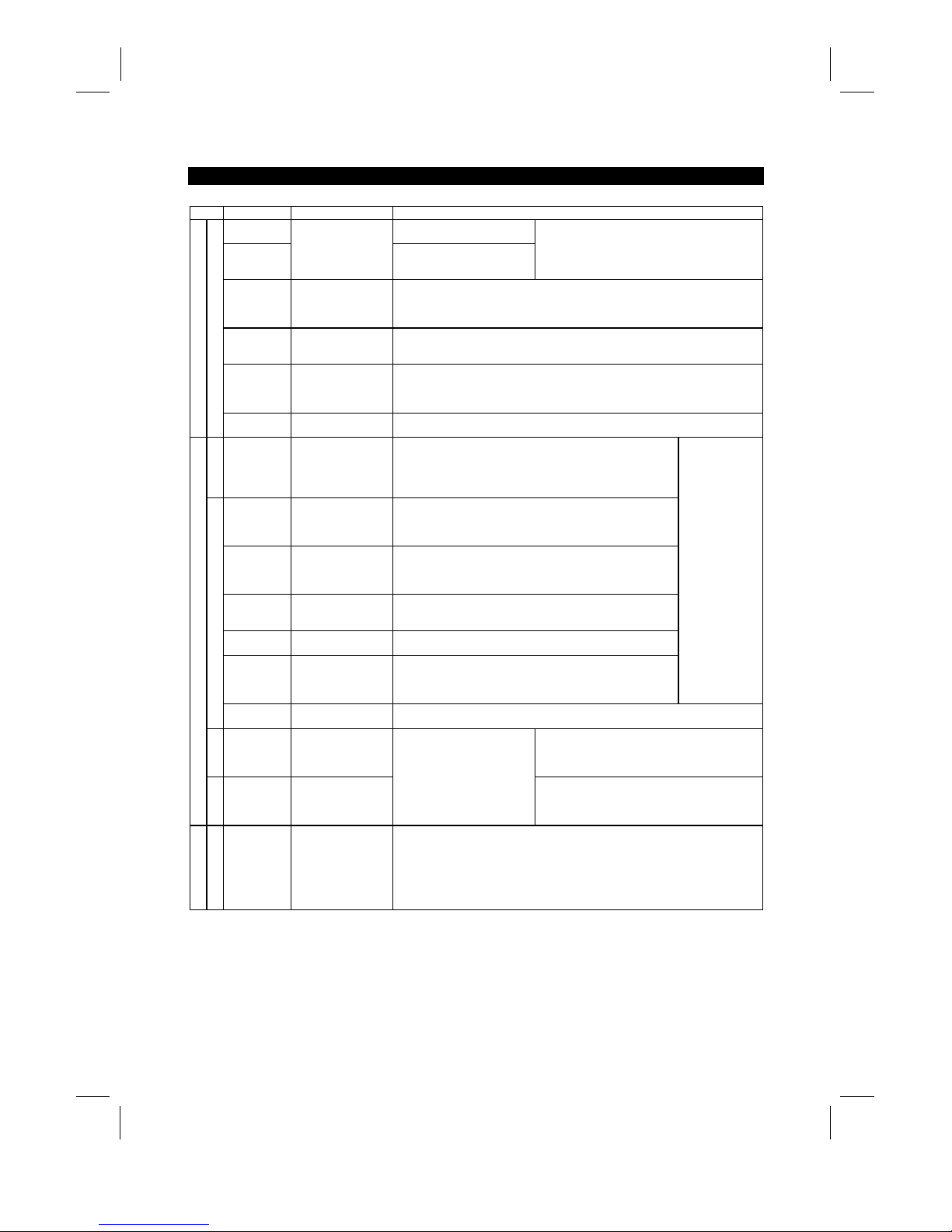
Type Symbol Terminal Name Description
10E
10VDC, permissible load
current 10mA
10
Frequency setting
power supply
5VDC, permissible load current
10mA
When the frequency setti ng potentiometer is
connected in the factory-set s tate, connect it to
terminal 10.
When it is connect ed t o terminal 10E, change the
input specifications of terminal 2.
2
Frequency setting
(voltage)
By entering 0 to 5VDC (0 to 10VDC), the maxim um output frequency is reached at 5V
(or 10V) and I/O are proportional. Switch between input 0 to 5V DC (f actory setting)
and 0 to 10VDC from the operation panel. Input resistance 10kΩ. Maximum
permissible voltage 20V.
4
Frequency setting
(current)
By entering 4 to 20mADC, the maxim um output frequency is reached at 20mA and
I/O are proportional. This input signal i s valid only when the AU signal is on. Input
resistance 250Ω. Maximum permissible current 30mA.
1
Auxiliary frequency
setting
By entering 0 to ±5VDC 0 to ±10VDC, this signal is added to the frequency setting
signal of terminal 2 or 4. Switch between input 0 to ±5VDC and 0 to ±10VDC (factory
setting) from the operation panel. I nput resistance 10kΩ. Maximum permissible
voltage ±20V.
Input signals
Analog frequency setting
5
Frequency setting
input common
Common to the frequency setting signal (terminal 2, 1 or 4) and analog output
terminal AM. Do not earth.
Contact
A, B, C Alarm output
Change-over contact output indicating t hat the output has been
stopped by the inverter protective function activated.
200VAC 0.3A, 30VDC 0.3A. Alarm: discontinuity across B-C
(continuity across A-C), norm al : continuity across B-C
(discontinuity across A-C).
RUN Inverter running
Switched low when the inverter output frequency is equal to or
higher than the starting frequency (factory set to 0.5Hz, variable).
Switched high during stop or DC dynamic brake operat i on (*2).
Permissible load 24VDC 0.1A.
SU Up to frequency
Switched low when the output frequency has reached within
±
10% of the set frequency (fact o ry setting, variable). Switched
high during acceleration, deceleration or s t op (*2). Permissible
load 24VDC 0.1A.
OL Overload alarm
Switched low when the stall prevention function has c aus ed stall
prevention to be activated. Switched high when stall prevention is
reset (*2). Permissible load 24VDC 0.1A.
IPF
Instantaneous power
failure
Switched low when instantaneous power failure or undervoltage
protection is activated (*2). P ermissible load 24VDC 0.1A.
FU Frequency detection
Switched low when the output frequency has reached or
exceeded the detection frequency set as appropriate. Switched
high when below the detection frequency (*2). Permiss i bl e l oad
24VDC 0.1A
Output terminal
function selection
(Pr. 190 to
Pr. 195) change
terminal
functions.
Open collector
SE
Open collector output
common
Common to the RUN, SU, OL, I P F and F U t erminals.
Pulse
FM For meter
Factory setting of output item:
Frequency
Permissible load current 1mA
1440 pulses/second at 60Hz
Output signals
Analog
AM Analog signal output
One selected from 16
monitoring items, s uch as
output frequency, is output. (*3)
The output signal is
proportional to the magnitude
of each monitoring item.
Factory setting of output item:
Frequency
Output signal 0 to 10VDC
Permissible load current 1mA
Communication
RS-485
PU connector
With the operation panel connector, communication can be made through RS-485.
·
Conforming Standard : EIA Standard RS -485
·
Transmission format : Multi-drop link
·
Communication speed : Maximum 19200 baud rat es
·
Overall length : 500m
*1: Terminals PR and PX are provided for the FR-A520-0.4K to 7.5K, FR-A540-0.4K to 7.5K.
*2: Low indicates that the open collector outputting transistor is on (conducts). High indicates that the
transistor is off (does not conduct).
*3: Not output while the inverter is reset.
Artisan Technology Group - Quality Instrumentation ... Guaranteed | (888) 88-SOURCE | www.artisantg.com
Page 23
INSTALLATION AND WIRING
12
2.2.2 Wiring of the main circuit
(1)
Wiring instructions
1) Crimping terminals with insulation sleeves are recommended for use with the power and motor cables.
2) Cut the protective bushes of the wiring cover when running the cables. (22K or less)
3) Power must not be applied to the output terminals (U, V, W) of the inverter . Otherwise the inverter will be
damaged.
4) After wiring, wire off-cuts must not be left in the inverter.
Wire off-cuts can cause an alarm, failure or malfunction. Always keep the inverter clean.
When drilling mounting holes in a control box etc., exercise care to prevent chips and other foreign matter
from entering the inverter.
5) Use cables of the recommended size for wiring to make the voltage drop 2% or less.
If the wiring distance is long between the inverter and motor, a main circuit cable voltage drop will cause
the motor torque to decrease especially at the output of a low frequency.
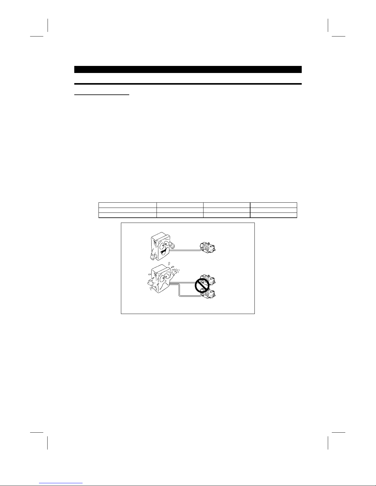
6) The overall wiring length should be 500m (1640.40feet) maximum.
Especially for long distance wiring, the overcurrent protection may be misactivated or the devices connected to the
output side may misoperate or become faulty under the influence of a charging current due to the stray capacitance
of the wiring. Therefore, the maximum overall wiring length should be as indicated in the following table. (When two
or more motors are connected to the inverter, the total wiring length should be within the indicated value.)
Inverter Capacity 0.4K 0.75K 1.5K or more
Non-low acoustic noise mode 300m (984.24 feet) 500m (1640.40 feet) 500m (1640.40 feet)
Low acoustic noise mode 200m (656.16 feet) 300m (984.24 feet) 500m (1640.40 feet)
Overall wiring length (1.5K or more)
300m (984.24 feet) + 300m (984.24 feet) = 600m (1968.48 feet)
500m
(1640.40 feet) maximum
300m
(984.24 feet)
300m
(984.24 feet)
7) Connect only the recommended optional brake resistor between the terminals P and PR 〈+ and PR〉.
These terminals must not be shorted.
8) Electromagnetic wave interference
The input/output (main circuit) of the inverter includes harmonic components, which may interfere with the
communication devices (such as AM radios) used near the inverter. In this case, install the FR-BIF optional radio
noise filter (for use in the input side only) or FR-BSF01 or FR-BLF line noise filter to minimize interference.
9) Do not install a power capacitor, surge suppressor or radio noise filter (FR-BIF option) in the output side of the
inverter.
This will cause the inverter to trip or the capacitor and surge suppressor to be damaged. If any of the above devices
are installed, immediately remove them. (If the FR-BIF radio nois e filter is connected, switching power off during
motor operation may result in E.UVT. In this case, connect the radio noise filter in the primary side of the
electromagnetic contactor.)
Artisan Technology Group - Quality Instrumentation ... Guaranteed | (888) 88-SOURCE | www.artisantg.com
Page 24
INSTALLATION AND WIRING
13
10) When rewiring after operation, m ake sure that the POW ER lam p has gone off, and when more than 10
minutes have elapsed after power-off, chec k with a tester that the voltage is zero. After that, s tart rewiring
work. For some time after power-off, there is a dangerous voltage in the capacitor.
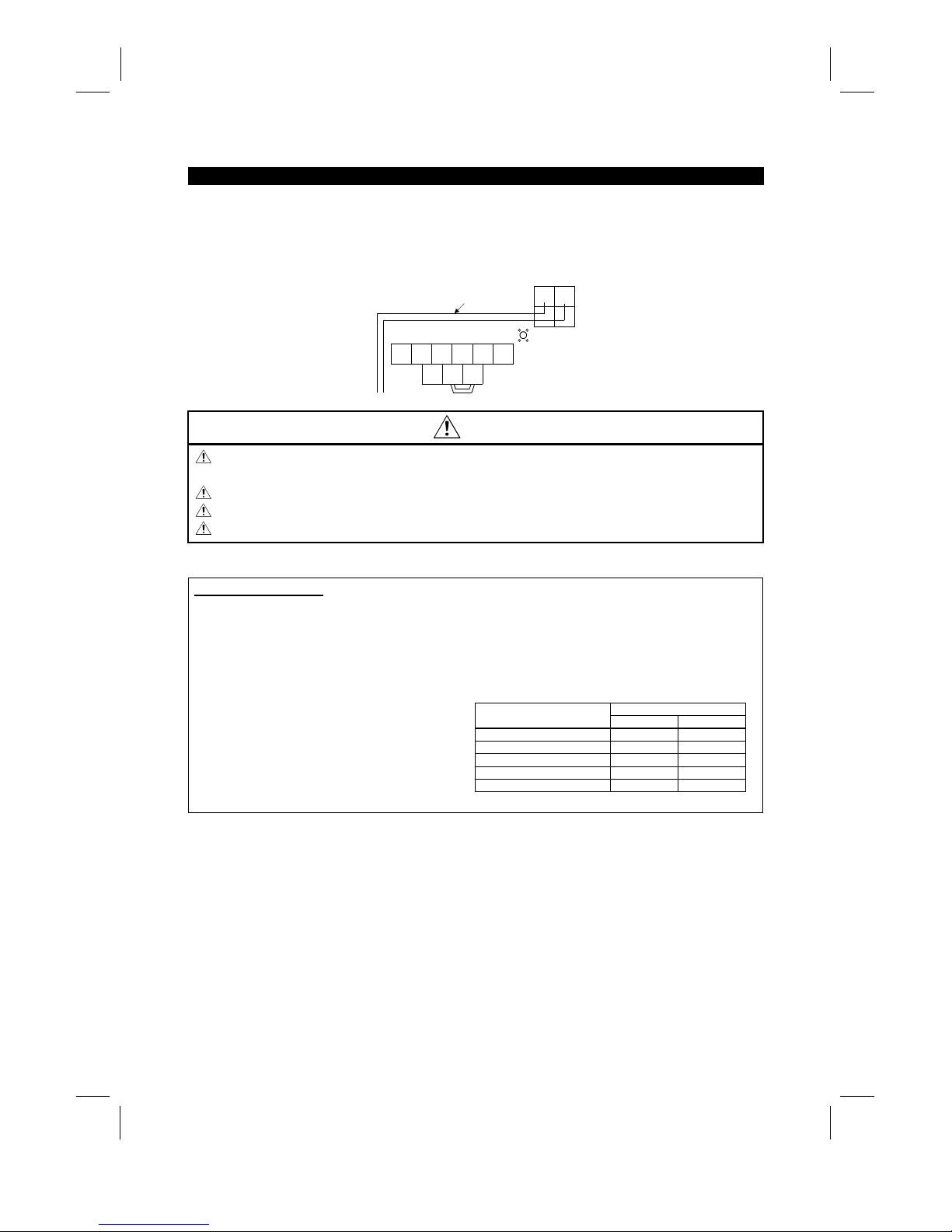
11) Use the space on the left-hand side of the m ain circuit terminal block to run the cable for c onnection of
the control circuit power terminals R1, S1 〈L
11
, L
21
〉
of the FR-A520-11K.
N
UVW
P1
R1 S1
P
Screw size (M5)
Connection cable
Charge lamp
T
〈L3〉
R
〈L1〉S〈L2〉
〈−〉 〈+〉
〈L11〉〈L21〉
CAUTION
Do not use residual current protective device as the only protection against indirect contact.
Protective earth connection essential.
Do not connect more than 2 wires on the protective earth terminal.
Use contactor and no fuse breaker EN/IEC standard compliant.
Use transformer or surge absorber EN/IEC standard compliant.
Notes on Grounding
•
Leakage currents flow in the inverter. To prevent an electric shock, the inverter and motor must be
grounded (200V class...class 3 grounding, grounding resis tance 100Ω maximum), (400V clas s... special
class 3 grounding, grounding resistance 10Ω or less.).
•
Use the dedicated ground terminal to ground the inverter. (Do not us e the screw in the case, chass is,
etc.)
(Unit: mm2)
Ground Cable Gauge
Motor Capacity
200V class 400V class
3.7kW (5HP) or less 3.5 2
5.5k, 7.5Kw (7.5HP, 10HP) 5.5 3.5
11 to 15Kw (15 to 20HP) 14 8
18.5 to 37kW (25 to 50HP) 22 14
45, 55Kw (60, 75HP) 38 22
•
The ground cable should be as thick as possible.
Its gauge should be equal to or larger than those
indicated in the following table. The grounding
point should be as near as possible to the inverter
to minimize the ground cable length.
•
Ground the motor on the inverter side using one
wire of the 4-core cable.
Artisan Technology Group - Quality Instrumentation ... Guaranteed | (888) 88-SOURCE | www.artisantg.com
Page 25
INSTALLATION AND WIRING
14
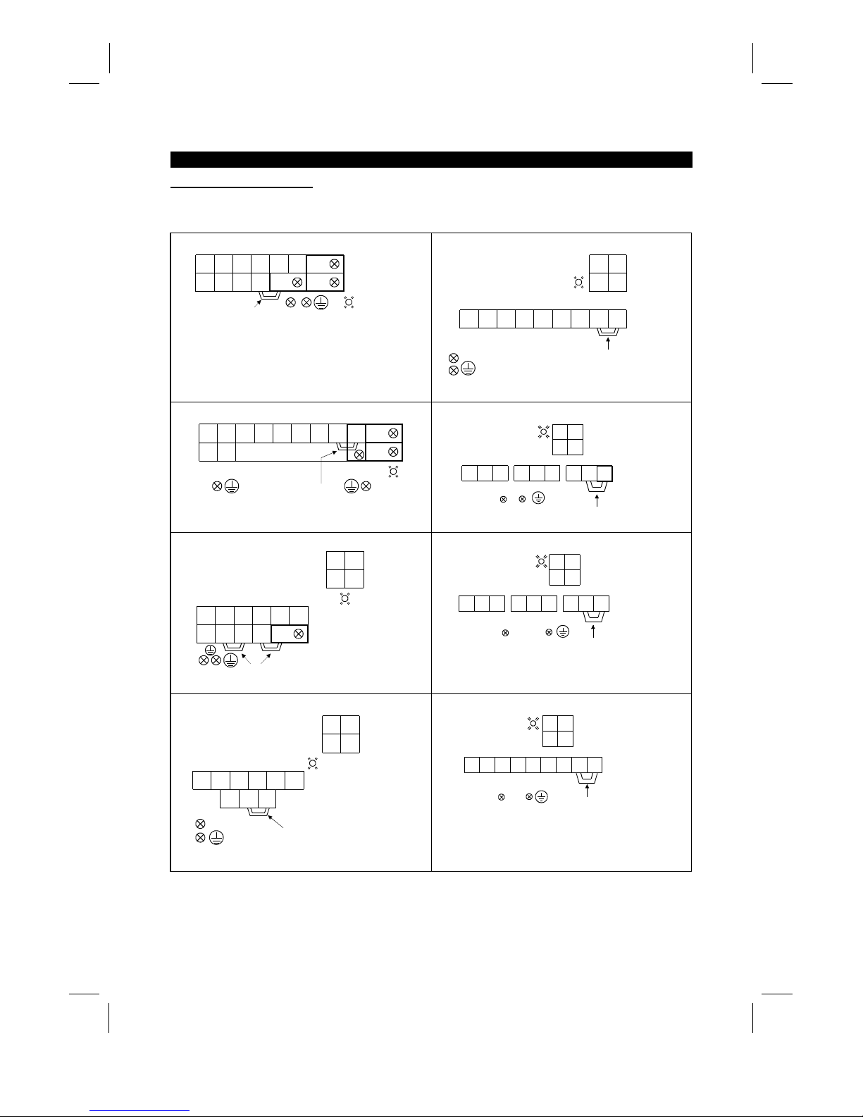
(2)
Terminal block layout
In the main circuit of the inverter, the terminals are arranged as shown below:
1) 200V class
FR-A520-0.4K, 0.75K
RR1STUVWPR
S1 N P1 P
(M4)
PX
Jumper
Screw size(M4)
Charge lamp
FR-A520-15K, 18.5K, 22K
RSTUVWNP1P
RS
R1 S1
Screw size
15K(M6)
18.5K,22K(M8)
Jumper
Charge lamp
Screw size (M4)
Screw size (M6)
FR-A520-1.5K, 2.2K, 3.7K
RR1STUVW PR
S1
NP1P
PX
(M4)
Jumper
Screw size (M4)
Charge lamp
FR-A520-30K
RST UVW
R1 S1
N P1 P
RS
Charge lamp
Screw size (M4)
Screw size (M8)
Screw size (M6) Jumper
FR-A520-5.5K, 7.5K
RNSTUVW
P1 P PR PX
R1RS1
S
(M5)
Jumpers
Charge lamp
Screw size
(M4)
Screw size(M5)
FR-A520-37K, 45K
RST UVW
R1 S1
N P1 P
RS
Charge lamp Screw size (M4)
Screw size (M10)
Screw size (M8)
Jumper
FR-A520-11K
RNSTUVW
P1 P
R1RS1
S
Jumper
Screw size (M4)
Charge lamp
Screw size (M5)
S
crew size (M5)
FR-A520-55K
RSTUVW
R1 S1
N P1 P
RS
Charge lamp
Screw size (M4)
Screw size (M12)
Screw size (M8)
Jumper
Artisan Technology Group - Quality Instrumentation ... Guaranteed | (888) 88-SOURCE | www.artisantg.com
Page 26
INSTALLATION AND WIRING
15
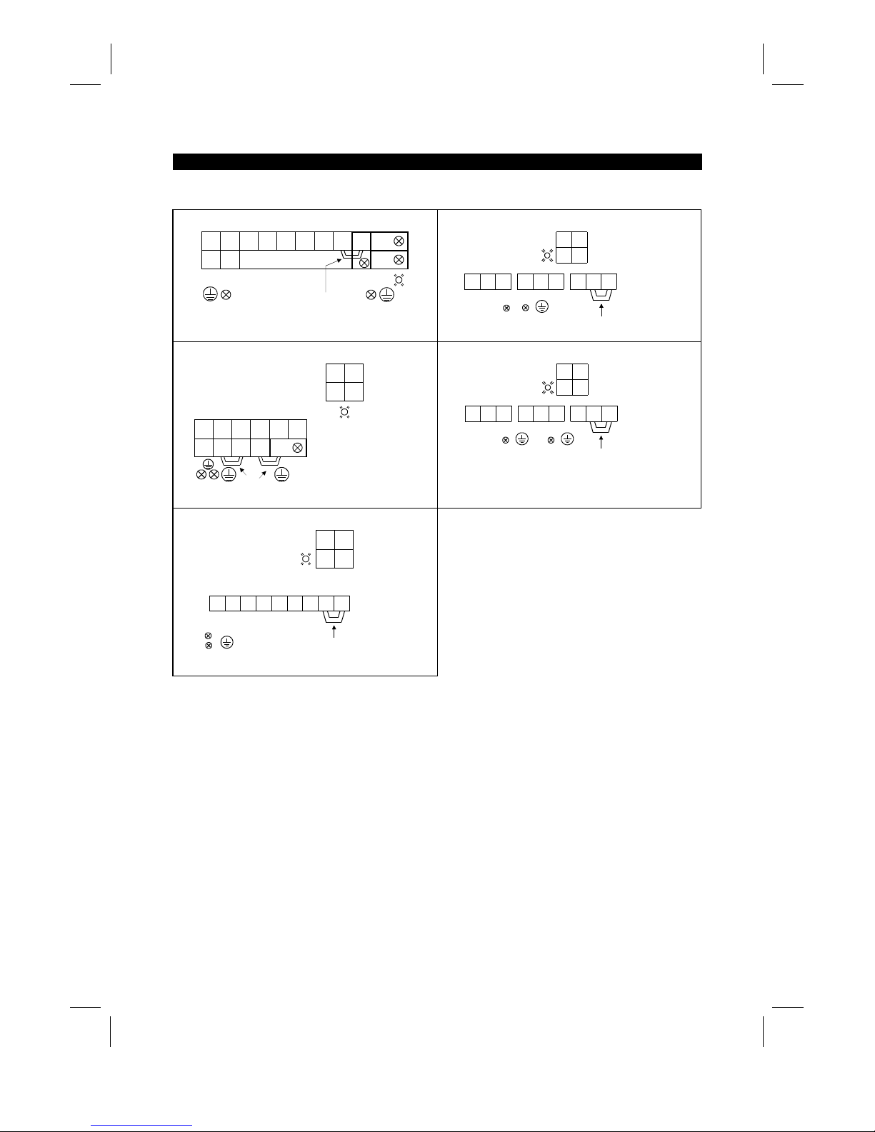
2) 400V class
FR-A540-0.4K, 0.75K, 2.2K, 3.7K
UVW PRP1
PX
(M4)
Screw size (M4)
Jumper
Charge lamp
R
〈L1〉S〈L2〉T〈L3〉
N
〈–〉P〈+〉
R1
〈
L
11
〉S1〈
L
21
〉
FR-A540-30K
UVW P1
Jumper
Screw size (M4)
Screw size (M6)
Screw size (M6)
Charge lamp
S
〈L2〉R〈L1〉T〈L3〉
R
〈L1〉S〈L2〉
R1
〈L11〉S1〈L12〉
N
〈–〉P〈+〉
FR-A540-5.5K, 7.5K
UVW
P1 PR PX
(M5)
Screw size (M4)
Charge lamp
Screw size (M4)
Jumpers
R
〈
L
1
〉S〈
L
2
〉T〈
L
3
〉
N
〈–〉
P
〈+〉
R
〈L1〉S〈L2〉
R1
〈L11〉S1〈L12〉
FR-A540-37K, 45K, 55K
S
〈
L
2
〉R〈
L
1
〉
UVW P1
Jumper
Screw size (M4)
Screw size (M8)
Screw size (M8)
Charge lamp
T
〈
L
3
〉
R
〈L1〉S〈L2〉
R1
〈L11〉S1〈L12〉
N
〈–〉P〈+〉
FR-A540-11K, 15K, 18.5K, 22K
S
〈
L
2
〉
UVW P1
Jumper
Screw size (M4)
Charge lamp
Screw size (M6)
Screw size (M6)
R
〈
L
1
〉T〈
L
3
〉
R
〈L1〉S〈L2〉
R1
〈L11〉S1〈L12〉
N
〈–〉P〈+〉
Note: 〈 〉 Terminal names in parentheses are those of the EC version.
Artisan Technology Group - Quality Instrumentation ... Guaranteed | (888) 88-SOURCE | www.artisantg.com
Page 27
INSTALLATION AND WIRING
16
(3)
Cables, crimping terminals, etc.
The following table lists the cables and crim ping terminals used with the inputs (R, S, T) 〈L1, L2, L
3
〉
and
outputs (U, V, W) of the inverter and the torques for tightening the screws:
Cables (Note 1)
Crimping Terminals
mm
2
AWG PVC
Applicable Inverter Type
Terminal
Screw
Size
Tightening
Torque
Kgf⋅cm
(N⋅m)
R, S, T
〈
L1, L2, L3
〉
U, V, W
R, S, T
〈
L1, L2, L3
〉
U, V, W
R, S, T
〈
L1, L2, L3
〉
U, V, W
R, S, T
〈
L1, L2, L3
〉
U, V,
W
FR-A520-0.4K to 2.2K M4 15 (1) 2-4 〈2.5-4〉2-4 〈2.5-4
〉
2 2 14 14 2.5 2.5
FR-A520-3.7K M4 15 (1) 5.5-4 〈4-4〉5.5-4 〈2.5-4
〉
3.5 3.5 12 12 4 2.5
FR-A520-5.5K M5 26 (2) 5.5-5 〈6-5〉5.5-5 〈4-5
〉
5.5 5.5 10 10 6 4
FR-A520-7.5K M5 26 (2) 14-5 〈16-5〉8-5 〈6-5
〉
14 8 6 8 16 6
FR-A520-11K M5 26 (2) 14-5 〈16-5〉14-5 〈16-5
〉
14 14 6 6 16 10
FR-A520-15K M6 45 (4) 22-6 〈35-6〉22-6 〈16-6
〉
22 22 4 4 35 16
FR-A520-18.5K M8 80 (7) 38-8 〈35-8〉38-8 〈25-8
〉
38 38 2 2 35 25
FR-A520-22K M8 80 (7) 38-8 〈70-8〉38-8 〈35-8
〉
38 38 2 2 70 35
FR-A520-30K M8 80 (7) 60-8 〈95-8〉60-8 〈30-8
〉
60 60 1/0 1/0 95 50
FR-A520-37K M10 150 (14) 100-10 〈95-8〉100-10 〈70-8〉100 100 4/0 4/0 75 70
FR-A520-45K M10 150 (14) 100-10 100-10 〈95-40〉100 100 4/0 4/0
−−
FR-A520-55K M12 250 (24) 150-12 150-12 〈110-12〉150 150 MCM300 MCM300
−−
FR-A540-0.4K to 3.7K M4 15 (1) 2-4 〈2.5-4〉2-4 〈2.5-4
〉
2 2 14 14 2.5 2.5
FR-540-5.5K M4 15 (1) 5.5-4 〈4-4〉2-4 〈2.5-4
〉
3.5 2 12 14 4 2.5
FR-540-7.5K M4 15 (1) 5.5-4 〈4-4〉5.5-4 〈4-4
〉
3.5 3.5 12 12 4 4
FR-540-11K M6 45 (4) 5.5-6 〈6-6〉5.5-6 〈6-6
〉
5.5 5.5 10 10 6 6
FR-540-15K M6 45 (4) 14-6 〈16-6〉8-6 〈10-6
〉
14 8 6 8 16 10
FR-540-18.5K M6 45 (4) 14-6 〈16-6〉8-6 〈10-6
〉
14 8 6 8 16 10
FR-540-22K M6 45 (4) 22-6 〈25-6〉14-6 〈16-6
〉
22 14 4 6 25 16
FR-540-30K M6 45 (4) 22-6 〈25-6〉22-6 〈25-6
〉
22 22 4 4 25 25
FR-540-37K M8 80 (7) 38-8 〈37-8〉22-8 〈25-8
〉
38 22 2 4 35 25
FR-540-45K M8 80 (7) 38-8 〈50-8〉38-8 〈35-8
〉
38 38 2 2 50 35
FR-540-55K M8 80 (7) 60-8 〈70-8〉60-8 〈50-8
〉
60 60 1/0 1/0 70 50
Note: 1. The cables used should be 75°C (167°F) copper cables.
2. Tighten the terminal screws to the specified torques.
Undertightening can cause a short or misoperation.
Overtightening can cause the screws and unit to be damaged, resulting in a short or
misoperation.
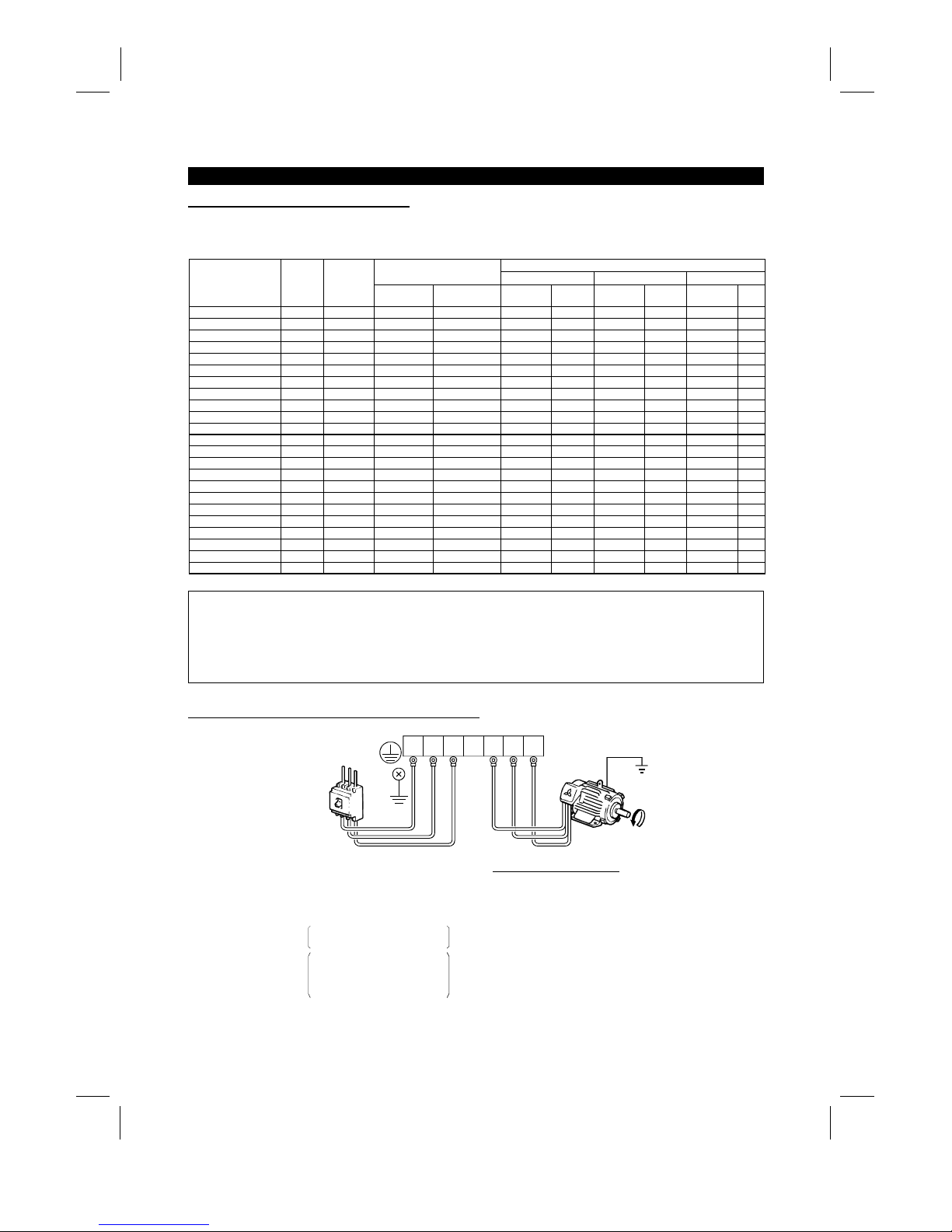
(4)
Connection of the power supply and motor
Ground
Ground
Ground
terminal
Power
supply
UVW
UVW
Motor
No-fuse
breaker
The power supply cables
must be connected to R, S, T
〈
L
1
, L2, L
3
〉
.
If they are connected to U, V,
W, the inverter will be damaged.
Phase sequence need not be
matched.
For use with a single-phase
power supply,the power supply
cables must be connected to
R and S 〈L
1
and L
2
〉
.
Connect the motor to U, V, W.
In the above connection,
turning on the forward rotation
switch (signal) rotates the motor
in the counterclockwise (arrow)
direction when viewed from
the load shaft.
R
〈
L
1
〉S〈
L
2
〉T〈
L
3
〉
R
〈
L
1
〉S〈
L
2
〉T〈
L
3
〉
Artisan Technology Group - Quality Instrumentation ... Guaranteed | (888) 88-SOURCE | www.artisantg.com
Page 28

INSTALLATION AND WIRING
17
(5)
Connecting the control circuit to a power supply separately from the main circuit
If the magnetic contactor (MC) in the inverter power supply is opened when the protective circuit is oper ated,
the inverter control circuit power is lost and the alarm output signal cannot be k ept on. To keep the alarm
signal on terminals R1 and S1 are available. In this case, c onnec t the power supply terminals R1 and S1 〈L
11
and L
21
〉
of the control circuit to the primary side of the MC.
• Model FR-A520-0.4K to 3.7K, FR-A540-0.4K to 3.7K
<Connection procedure>
R
〈L1〉
S
〈L2〉
T
〈L3〉
R1 〈L11〉
S1 〈L21〉
4) Connect the separate power supply cables for control circuit to the
lower terminals (R1, S1 〈L11, L21〉). (Note 4)
Terminal block for main circuit
1) Loosen the upper screws
2) Remove the lower screws.
3) Remove the jumpers.
• Model FR-A520-5.5K to 55K, FR-A540-5.5K to 55K
<Connection procedure>
M
C
1) Loosen the upper screws.
2) Remove the lower screws.
3) Pull out and remove the jumper.
4) Connect the separate power supply
cables for control circuit to the
upper terminals (R1, S1 〈L11, L21〉). (Note 4)
Power supply terminal
block for control circuit
Main power supply
Power supply terminal
block for control circuit
R
〈
L
1
〉S〈
L
2
〉T〈
L
3
〉
R1
〈
L
11
〉S1〈
L
21
〉
Note: 1. When the main circuit power (R, S, T ) 〈L1 L2, L
3
〉
is on, do not switch off the control power
(terminals R1, S1 〈L
11
, L
21
〉
). Otherwise the inverter may be damaged.
2. W hen using a separate power supply, the jumpers acros s R-R1 and S-S1 〈L
1
-
L
11
and L
2
-
L
21
〉
must be removed. Otherwise the inverter may be damaged.
3. For a diff erent power supply system which takes the power of the control c ircuit from other than
the primary side of the MC, the voltage should be equal to the main circuit voltage.
4. For the FR-A520-5.5K to 55K, FR-A540-5.5K to 55K, the power supply cables must not be
connected to the lower terminals. If connected, the inverter may be damaged.
Artisan Technology Group - Quality Instrumentation ... Guaranteed | (888) 88-SOURCE | www.artisantg.com
Page 29

INSTALLATION AND WIRING
18
2.2.3 Wiring of the control circuit
(1)
Wiring instructions
1) Terminals SD, SE and 5 are com mon to the I/O signals and isolated from each other . These common
terminals must not be connected to each other or earthed.
2) Use shielded or twisted cables for connection to the control circuit terminals and run them away from the
main and power circuits (including the 200V relay sequence circuit).
3) The frequency input signals to the control circuit are m icro currents . W hen contacts are required, use two
or more parallel micro signal contacts or a twin contact to prevent a contact fault.
4) It is recommended to use the cables of 0.75mm
2
gauge for connection to the control circuit term inals.
If the cable gauge used is 1.25mm
2
or more, the front cover may be lifted when there are many cables
running or the cables are run improperly, resulting in an operation panel or parameter unit contact fault.
(2)
Terminal block layout
•
Japanese and NA version
In the control circuit of the inverter, the terminals are arranged as shown below:
Terminal screw size: M3.5
A
RL
SE RUN SU IPF OL FU SD STF STR JOG CS
RM RH RT AU STOP MRS RES SD FM
B C PC AM 10E 10 2 5 4 1
•
EC version
Terminal screw size: M3.5
A
SE RUN SU LPF OL STOP MRS RES PC STF
B C SD AM 10E 10 2 5 4 1 RL RM RH RT AU
STR JOG CS FM SDFU
<Wiring procedure>
1) For the wiring of the control circuit, strip the sheaths of the cables and use them as they are.
Strip the sheath to the following dimension. A too long stripping dimens ion may cause a short circuit with
the neighboring cable. A too short dimension may cause cable disconnection.
6mm ± 1mm
2) Loosen the terminal screw and insert the cable into the terminal.
3) Tighten the screw to the specified torque.
Undertightening can cause cable disconnection or malfunction. Overtightening can cause a short circuit or
malfunction due to the screw or unit damaged.
Tightening torque: 5 to 6 kgf⋅cm
Note: Wire the stripped cable by twisting it to prevent it from becoming loose. (Do not plate the cable with
solder.)
Note: 1. Use a NFB (No fuse breakers) or fuse on the inverter input (primary) side.
2. Make sure that the control circuit terminal wiring does not touch power circuit terminals (or
screws) or conducting power circuit.
Artisan Technology Group - Quality Instrumentation ... Guaranteed | (888) 88-SOURCE | www.artisantg.com
Page 30
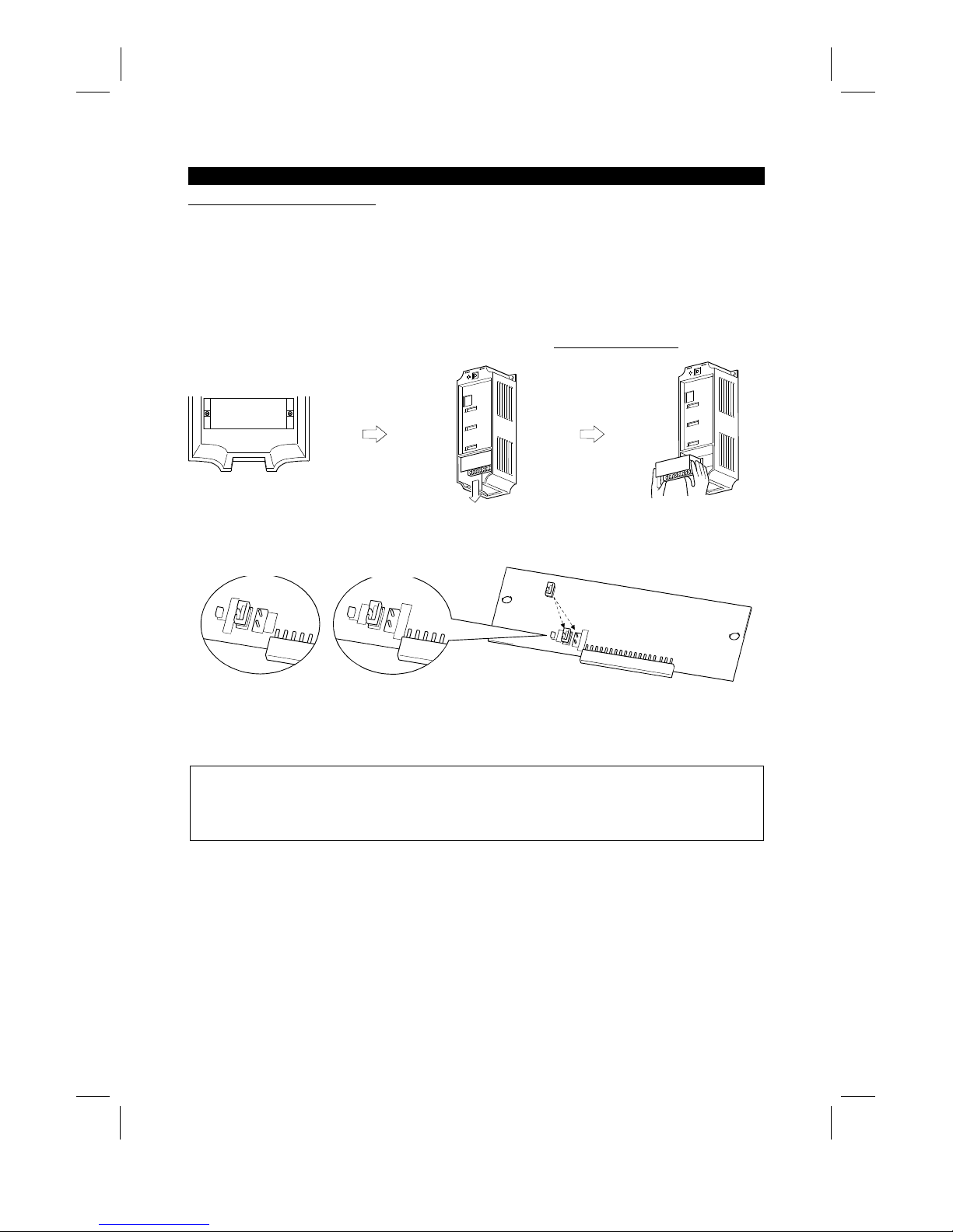
INSTALLATION AND WIRING
19
(3)
Changing the control logic
The input signals are set to sink logic f or the Japanese and NA version, and to source Logic for the EC
version.
To change the control logic, the connector on the back of the control circuit terminal block must be moved to
the other position.
(The output signals may be used in either the sink or source logic independently of the connector position.)
1) Loosen the two mounting screws in both ends of the control c ircuit terminal bloc k. (T he screws cannot be
removed.)
With both hands, pull down the terminal block from the back of the control circuit terminals.
2) Remove the connector from the rear surface of the control c ircuit terminal block and place in required
Logic position (either Sink or Source).
SOURCE
CON3
CON2
SINK
CON1
SINK
CON3
CON2
SOURCE
SINK
CON3
CON2
SOURCE
EC version
NA and Japanese version
3) Using care not to bend the pins of the control circuit c onnector, reinstall the control circuit ter minal block
and fix it with the mounting screws.
Note: 1. Make sure that the control circuit connector is fitted correctly.
2. While power is on, never disconnect the control circuit terminal block.
3. The sink -source logic change-over connec tor mus t be fitted in only one of those positions. If it is
fitted in both positions at the same time, the inverter may be damaged.
Artisan Technology Group - Quality Instrumentation ... Guaranteed | (888) 88-SOURCE | www.artisantg.com
Page 31

INSTALLATION AND WIRING
20
4) Sink logic type
•
In this logic, a signal switches on when a current flows out of the corresponding signal input terminal.
Terminal SD is com mon to the contact input signals. Terminal SE is com mon to the open collector
output signals.
R
R
STF
STR
SD
Current
RUN
SE
EX. A current flows out of
the corresponding signal RUN
•
When using an external power supply for trans istor output, use terminal PC as a common to prevent
misoperation caused by leakage current. (Do not connec t terminal SD of the inverter with term inal 0V of
the external power supply.)
1
2
3
4
5
6
9
10
DC24V
SD
PC
RES
RL
RM
RH
STR
STF
DC24V
(SD)
AY40 type
transistor outp ut
module
Inverter
Artisan Technology Group - Quality Instrumentation ... Guaranteed | (888) 88-SOURCE | www.artisantg.com
Page 32

INSTALLATION AND WIRING
21
5) Source logic type
•
In this logic, a signal switches on when a current flows into the corresponding s ignal input terminal.
Terminal PC is com mon to the contact input signals. Terminal SE is comm on to the open collector
output signals.
PC
STF
STR
R
R
Current
RUN
SE
EX. A current flows out of
the corresponding signal RUN
•
When using an external power supply for trans istor output, use terminal SD as a comm on to prevent
misoperation caused by leakage current.
AY-80
9
1
2
10
PC
STF
STR
SD
DC24V
(SD)
DC24V
Inverter
(4)
How to use terminals "STOP", "CS" and "PC"
1) Using the "STOP" terminal
A connection example (for sink logic) for self-holding the start signal (forward
rotation, reverse rotation) is shown on the right.
2) Using the "CS" terminal
This terminal is used to perform automatic restart after instantaneous power failure
and commercial power supply-inverter switch-over operation.
<Example: Automatic restart after instantaneous power failure in sink logic>
Connect terminals CS-SD and set a value other than "9999" in Pr. 57 "coasting time
for automatic restart after instantaneous power failure".
MRS
RES
SD
STF
STR
STOP
Reverse
rotation
Stop
Forward
rotation
CS SD
(Short)
3) Using the "PC" terminal
This terminal can be used as 24VDC power output using SD as a common terminal.
Specifications: 18V to 26VDC, 0.1A permissible current
Note that the wiring length should be within 30m.
Do not short terminals PC-SD.
When terminal PC is used as a 24V power supply, leakage current from transistor output cannot be
prevented.
Artisan Technology Group - Quality Instrumentation ... Guaranteed | (888) 88-SOURCE | www.artisantg.com
Page 33

INSTALLATION AND WIRING
22
2.2.4 Connection to the PU connector
(1)
When connecting the operation panel or parameter unit using a connection cable
<Recommended cable connector>
•
Parameter unit connection cable (FR-CB2) (option) or the following connector and cable.
•
Connector: RJ45 connector
Example: 5-554720-3, Nippon AMP
•
Cable: Cable conforming to EIA568 (e.g. 10BASE-T cable)
Example: SGLPEV 0.5mm×4P, MITSUBISHI CABLE INDUSTRIES, LTD.
Note: The maximum wiring length is 20m (65.62 feet).
(2)
For RS-485 communication
With the operation panel disconnected, the PU c onnector can be used f or communic ation operation from a
personal computer etc.
When the PU connector is connected with a personal, FA or other computer by a comm unication cable, a
user program allows the inverter to be run and monitored and the parameter values to be read and written.
<PU connector pin-outs>
Viewed from the inverter (receptacle side) front
1) SG
2) P5S
3) RDA
4) SDB
5) SDA
6) RD
B
7) SG
8) P5S
1)
8)
Note: 1. Do not connect the PU connector to the computer's LAN board, FAX modem socket or
telephone modular connector. Otherwise, the product may be damaged due to electrical
specification differences.
2. Pins 2 and 8 (P5S) provide power to the operation unit or parameter unit. Do not use these pins
for RS-485 communication.
<System configuration example>
1) When a computer having a RS-485 interface is used with several inverters
PU connectorPU connector
Computer
Inverter
Station 1
PU connector
Inverter
Station 2
Inverter
Station n
RS-485
interface/terminal
C
omputer
10BASE-T
cable
Terminal resistor jumper
Distribution terminal
Note: 1. Use the connector and cables which are available on the market.
x
Connector: RJ45 connector
Example: 5-554720-3, Nippon AMP Co., Ltd.
x
Cable: Cable conforming to EIA568B (such as 10BASE-T cable)
Example: SGLPEV 0.5mm×4P, Mitsubishi Cable Industries, Ltd.
Artisan Technology Group - Quality Instrumentation ... Guaranteed | (888) 88-SOURCE | www.artisantg.com
Page 34

INSTALLATION AND WIRING
23
2) When a computer having a RS-232C interface is used with inverters
Computer
Inverter
Station 1
PU connector
Inverter
Station 2
PU connector
Inverter
Station n
PU connector
Terminal resistor jumper
Max. 15m
RS-232C connector
RS-232C cable
RS-485 terminal
*Converter
*Converter available on the market is required.
10BASE-T cable
Distribution terminal
Note: 1. Use the connector, cables and converter which are available on the market.
x
Connector: RJ45 connector
Example: Nippon AMP Co., Ltd.
x
Cable: Cable conforming to EIA568B (such as 10BASE-T cable)
Example: SGLPEV 0.5mm×4P, Mitsubishi Cable Industries, Ltd.
x
RS-485/RS-232C converter
Example: FA-T-RS40, Industrial System Div., Mitsubishi Electric Engineering Co., Ltd.
or
: Cable with built-in interface DAFXI-CAB series, Connector conversion cable
DINV-485CAB, Dia Trend Co., Ltd.
<Wiring method>
1) Wiring of one computer and one inverter
Computer Side Terminals
Signal name Description
RDA
RDB
SDA
SDB
RSA
RSB
CSA
CSB
SG
FG
Receive data
Receive data
Send data
Send data
Request to send
Request to send
Clear to send
Clear to send
Signal ground
Frame ground
PU connector
SDA
SDB
RDA
RDB
RDR
SG
*2
∗1 Terminal resistor
jumper
0.3mm or more
2
Cable connection and signal direction
10BASE-T Cable
Inverter
2) Wiring of one computer and "n" inverters (several inverters)
*2
Computer
RDA
RDB
SDA
SDB
RSA
RSB
CSA
CSB
SG
FG
Station 1
SG
RDB
RDA
SDB
SDA
Station 2
SG
RDB
RDA
SDB
SDA
Station 3
SG
RDR
RDB
RDA
SDB
SDA
Terminal
resistor
jumper (*1)
Inverter
Inverter Inverter
Note: 1. Connect the terminal resistor jumper only to the inverter remotest from the computer.
(Terminal resistor: 100 Ω)
2. Make connections in accordance with the instruction manual of the computer used.
Fully check the terminal numbers of the computer as they differ between models.
Artisan Technology Group - Quality Instrumentation ... Guaranteed | (888) 88-SOURCE | www.artisantg.com
Page 35

INSTALLATION AND WIRING
24
2.2.5 Connection of stand-alone option units
The inverter accepts a variety of stand-alone option units as required.
Incorrect connection will cause inverter dam age or accident. Connect and operate the option unit car efully in
accordance with the corresponding option unit manual.
(1)
Connection of the dedicated external brake resistor (option)
The built-in brake resistor is connected across terminals P 〈+〉 and PR. Fit the external dedicated brake
resistor (option) instead when the built-in brake resistor does not have enough therm al c apability for high-duty
operation. Remove the jumper from across terminals PR-PX and connect the dedicated brake resistor
(option) across terminals P-PR 〈+ -PR〉.
(For the positions of terminals P and PR, refer to the terminal block arrangement (page14 and 15).)
Note: 1. The brake resistor connected should only be the dedicated brake resistor.
2. The jumper across terminals PR-PX must be disconnected before connecting the dedicated
brake resistor. A failure to do so may damage the inverter.
• Model...............FR-A520-0.4K to 3.7K, FR-A540-0.4K to 3.7K
1) Remove the screws in terminals PR and PX and remove the jumper.
2) Connect the brake resistor across terminals P-PR 〈+ -PR〉.
(The jumper should remain disconnected.)
Removal of jumper FR-A520-0.4K, 0.75K
FR-A520-1.5K to 3.7K
FR-A540-0.4K to 3.7K
Terminal PX
Terminal PR
Jumpe
r
Terminal PR
Terminal P
Terminal P
R
Terminal P
• Model ...............FR-A520-5.5K, 7.5K, FR-A540-5.5K, 7.5K
1) Remove the screws in terminals PR and PX and remove the jumper.
2) Connect the brake resistor across terminals P-PR 〈+ -PR〉.
(The jumper should remain disconnected.)
Removal of jumper
FR-A520-5.5K, 7.5K
FR-A540-5.5K, 7.5K
Jumper
T
erminal PR
Terminal PX
Terminal PR
Terminal PR
Artisan Technology Group - Quality Instrumentation ... Guaranteed | (888) 88-SOURCE | www.artisantg.com
Page 36

INSTALLATION AND WIRING
25
(2)
Connection of the FR-BU brake unit (option)
Connect the optional FR-BU brake unit as shown below to improve the braking capability during deceleration.
MC
R 〈L1〉
S 〈L2〉
T 〈L3〉
U
V
W
〈+〉 P
〈–〉
N
PR
PX
IM
PR
P/+
N/-
HA
HB
HC
Brake unit
FR-BU-(H)
Resistor unit
FR-BR-(H)
THS TH2
TH1
PPR
ON
MC
OFF
MC
Remove jumper.
Inverter
Motor
T (Note 4)
Note: 1. Connect the inverter terminals (P, N) 〈+, −〉 and FR-BU brake unit terminals so that their term inal
signals match with each other. (Incorrect connection will damage the inverter.) For model 7.5K or
less, the jumper across terminals PR-PX must be removed.
2. The wiring distance between the inverter, br ake unit and r esistor unit should be within 5m ( 16.40
feet). If twisted wires are used, the distance should be within 10m (32.8 feet).
3. If the transistors in the brake unit should fail, the resis tor will be extremely hot, causing a fire.
Therefore, install a magnetic c ontac tor on the inver ter's power s upply side to shut off a current in
case of failure.
4. For the power supply of 400V class, install a voltage-reducing transformer.
Artisan Technology Group - Quality Instrumentation ... Guaranteed | (888) 88-SOURCE | www.artisantg.com
Page 37

INSTALLATION AND WIRING
26
(3)
Connection of the conventional BU brake unit (option)
Connect the BU brake unit correctly as shown on the right. Incorrect connection will damage the inverter.
MC
R 〈L
1
〉
S 〈L2〉
T 〈L
3
〉
U
V
W
IM
Inverter
HCHBHA TB
HC HB
ON
MC
MC
OFF
P 〈+〉 N 〈–〉
P
OCR
PR
OCR
N
NFB
PC
Brake unit
Remove jumpers.
Discharge resistor
Constant-voltage
power supply
BU brake unit
Comparator
Motor
T (Note 4)
+
-
Note: 1. For models 7.5K or less, remove the jumper across terminals PR-PX.
2. The wiring distance between the inverter, brake unit and discharge resistor should be within
2m (6.56 feet).
If twisted wires are used, the distance should be within 5m (16.40 feet).
3. If the transistors in the brake unit should fail, the resis tor will be extremely hot, causing a fire.
Therefore, install a magnetic c ontactor on the inverter's power supply side to shut off curr ent in
case of failure.
4. For the power supply of 400V class, install a voltage-reducing transformer.
(4)
Connection of the FR-HC high power factor converter (option)
When connecting the high power factor converter ( FR-HC) to suppress power harmonics, wire as shown
below. Wrong connection will damage the high power factor converter and inverter.
After making sure that the wiring is correct, set "2" in Pr. 30 "regenerative function selection".
X10 (Note 3)
X11 (Note 3)
N 〈–
〉
P 〈+〉
R1 〈L
11
〉
S1 〈L21〉
RES
SD
T 〈L
3
〉
S 〈L2〉 (Note 1)
R 〈L1〉
NFB
R S T R4 S4 T4 N P Y1 or Y2 RDY RSO SE
Inverter
(FR-A500)
(Note 1)
High power factor converter
From FR-HCL02
Power
supply
Artisan Technology Group - Quality Instrumentation ... Guaranteed | (888) 88-SOURCE | www.artisantg.com
Page 38

INSTALLATION AND WIRING
27
Note: 1. Remove the jumpers across the R-R1 and S-S1 〈L
1
-
R1 and L
2
-
S1〉 terminals of the inverter, and
connect the control circuit power supply across the R1-S1 〈L
11
-
L
21
〉
terminals. The power input
terminals R, S, T 〈L
1
, L2, L
3
〉
must be open.
Incorrect connection will damage the inverter. Reverse polarity of terminals N (−), P (+) will
damage the inverter.
2. The voltage phases of term inals R, S, T 〈L
1
, L2, L
3
〉
and terminals R4, S4, T4 mus t be matched
before connection.
3. Use Pr. 180 to Pr. 186 (input ter minal function selection) to assign the term inals used with the
X10 and X11 signals.
4. W hen the FR-HC is connected, use sink logic (factory setting). For source logic, the FR-HC
cannot be connected. (For the EC version, select the sink logic.)
(5)
Connection of the FR-RC power return converter (option)
(For power coordination, always install the power factor improving reactor (FR-BAL).)
When connecting the FR- RC power return conver ter, connec t the inverter term inals (P, N) and F R-RC power
return converter terminals as shown below so that their signals match with each other. Af ter m ak ing sur e that
the wiring is correct, set "0" in Pr. 30 "regenerative function selection".
NP
NFB FR-BAL
R/L1 S/L2 T/L3
P/+
N/−
FR-RC power return converter
Power supply
Inverter
R
〈
L
1
〉S〈
L
2
〉T〈
L
3
〉
Note: 1. For models 11K or less, the jumper across terminals PR-PX must be removed.
2. How to connect the FR-BAL power factor improving AC reactor (option)
When using two or more inverters in the same system, small impedance between the inverters
will cause a regenerative current from the power return converter to leak into the other inverters,
resulting in overcurrent alarm of the other inverters. To prevent this, install a power factor
improving AC reactor on the power supply side for all the inverters.
(6)
Connection of the power factor improving DC reactor (option)
Connect the FR-BEL power factor improving DC
reactor between terminals P1-P 〈P1-
+〉
. In this
case, the jumper connected acros s terminals P1-P
〈
P1
- +〉
must be removed. Otherwise, the reactor
will not function.
•
<Connection method>
P1
P
FR-BEL
Remove
the jumper.
〈+〉
Note: 1. The wiring distance should be within 5m.
2. The size of the cables used should be equal to or larger than that of the power supply cables
(R, S, T) 〈L
1
, L2, L
3
〉
.
Artisan Technology Group - Quality Instrumentation ... Guaranteed | (888) 88-SOURCE | www.artisantg.com
Page 39

INSTALLATION AND WIRING
28
2.2.6 Design information
1) For commercial power supply-inverter switch-over operation, provide electrical and mechanical interlocks
for MC1 and MC2 designed for commercial power supply-inverter switch-over.
When there is a commercial power supply-inverter switch-over circuit as shown below, the inverter will be
damaged by leakage current from the power supply due to arcs generated at the time of switch-over or
chattering caused by a sequence error.
2) If the machine must not be restarted when power is restored after a power failure, pr ovide a magnetic
contactor in the inverter's primar y circuit and also make up a sequence which will not switch on the s tart
signal.
If the start signal (start switch) rem ains on after a power failure, the inver ter will automatically restart as
soon as the power is restored.
3) When the power supply used with the control circuit is dif ferent from the one used with the main c ircuit,
make up a circuit which will switch off the main circ uit power supply terminals R, S, T 〈L
1
, L2, L
3
〉
when the
power supply terminals R1, S1 〈L
11
, L
21
〉
for the control circuit are switched off.
4) Since the input signals to the control circuit are on a low level, use two parallel micro signal contac ts or a
twin contact for contact inputs to prevent a contact fault.
5) Do not apply a large voltage to the contact input terminals (e.g. STF) of the control circuit.
6) Do not apply a voltage directly to the alarm output signal terminals (A, B, C).
Always apply a voltage to these terminals via a relay coil, lamp, etc.
7) Make sure that the specifications and rating match the system requirements.
1) Commercial power supply-inverter switch-over
U
V
W
R (L1)
S (L
2
)
T (L
3
)
IM
MC2
MC1
Interloc
k
Leakage current
Inverter
Power
supply
4) Low-level signal contacts
Twin contact
L
ow-level signal contacts
Artisan Technology Group - Quality Instrumentation ... Guaranteed | (888) 88-SOURCE | www.artisantg.com
Page 40

2.3 Other wiring
INSTALLATION AND WIRING
29
2.3 Other wiring
2.3.1 Power harmonics
Power harmonics may be generated from the converter section of the inverter, affecting power supply
equipment, power capacitors, etc. Power harmonics are different in generation source, frequency and
transmission path from radio frequency (RF) noise and leakage currents. Take the following measures.
•
The differences between harmonics and RF noise are indicated below:
Item Harmonics RF Noise
Frequency Normally 40 to 50th degrees, 3kHz or les s High frequency (several 10k Hz to MHz order)
Environment To wire paths, power impedance Acc ros s spaces, distance, laying paths
Quantitative understanding Logical computation is possible Occurs randomly, quantitative understandi ng i s difficult.
Generated amount Approximately proportional to load capacity
According to current fluctuat ion rate (larger with faster
switching)
Immunity of affected device Specified in standards for each device. Differs according to m aker’s device specifications.
Example of safeguard Inst al l a reactor Increase the distance.
•
Safeguard
The harmonic current generated from the inverter to the
power supply differs according to various conditions such as
the wiring impedance, whether a power factor improving
reactor is used or not, and output frequency and output
current on the load side.
For the output frequency and output current, the adequate
method is to obtain them under rated load at the m aximum
operating frequency.
NFB
IMInverter
Power factor
improving DC
reactor
Motor
Do not insert power factor
improving capacitor
Power factor
improving AC
reactor
Note: A power factor im proving capacitor or sur ge suppressor on the inverter’s output may overheat or be
damaged due to the harmonics of the inverter output. Also, when an overcurrent flows in the inverter,
the overcurrent protection is activated, Hence, when the motor is driven by the inverter, do not install
a capacitor or surge suppressor on the inverter’s output. To im prove the power fac tor, inser t a power
factor improving reactor in the inverter’s input or DC circuit.
Artisan Technology Group - Quality Instrumentation ... Guaranteed | (888) 88-SOURCE | www.artisantg.com
Page 41

INSTALLATION AND WIRING
30
2.3.2 Japanese harmonic suppression guidelines
Harmonic currents flow from the inverter to a power receiving point via a power trans former. The harm onic
suppression guidelines were established to protect other consumers from these outgoing harmonic currents.
1) "Harmonic suppression guideline for household appliances and general-purpose products"
This guideline was issued by the Ministry of International Trade and Industries in Septem ber, 1994 and
applies to 200V class inverters of 3.7k W (5HP) and less. By installing the FR-BEL or FR-BAL power f actor
improving reactor, inverters comply with the "harmonic suppres sion techniques for transis torized inverters
(input current 20A or less)" established by the Japan Electrical Manufacturers' Association. Therefore
install the optional reactor for the 200V class, 3.7kW (5HP) or less inverter.
2) "Harmonic suppression guideline for specific consumers"
This guideline sets forth the maximum values of harmonic currents outgoing from a high-voltage or
especially high-voltage consumer who will install, add or renew harmonic generating equipment. If any of
the maximum values are exceeded, this guideline requires that consumer to take certain suppression
measures.
Table 1 Maximum Values of Outgoing Harmonic Currents per 1kW Contract Power
Received Power
Voltage
5th 7th 11th 13th 17th 19th 23rd Over 23rd
6.6kV 3.5 2.5 1.6 1.3 1.0 0.9 0.76 0.70
22kV 1.8 1.3 0.82 0.69 0.53 0.47 0.39 0.36
33kV 1.2 0.86 0.55 0.46 0.35 0.32 0. 26 0.24
(1)
Application of the harmonic suppression guideline for specific consumers
New installation/addition/renewal of equipment
Sum of equivalent capacities
Over reference capacity
Is outgoing harmonic cur-
rent equal to or lower than
maximum value
?
Over maximum value
Not more than
maximum value
Not more than
reference capacity
Calculation of equivalent capacity sum
Calculation of outgoing harmomic current
Harmomic suppression technique is required.
Harmomic suppression technique is not required.
Table 2 Conversion Factors for FR-A500 Series
Class Circuit Type Conversion Factor
Without reactor K31 = 3.4
With reactor (AC side) K32 = 1.8
With reactor (DC side) K33 = 1.8
3
3-phase bridge
(Capacitor-smoothed)
With reactors (AC, DC sides) K34 = 1.4
5 Self-exciting 3-phase bridge When high power factor converter is used K5 = 0
Artisan Technology Group - Quality Instrumentation ... Guaranteed | (888) 88-SOURCE | www.artisantg.com
Page 42

INSTALLATION AND WIRING
31
Table 3 Equivalent Capacity Limits
Received Power Voltage Reference Capacity
6.6kV 50kVA
22/33kV 300kVA
66kV or more 2000kVA
Table 4 Harmonic Content (Values at the fundamental current of 100%)
Reactor 5th 7th 11th 13th 17th 19th 23rd 25th
Not used 65 41 8.5 7.7 4.3 3.1 2.6 1.8
Used (AC side) 38 14. 5 7.4 3.4 3.2 1.9 1.7 1.3
Used (DC side) 30 13 8.4 5.0 4.7 3.2 3.0 2.2
Used (AC, DC sides) 28 9.1 7.2 4.1 3.2 2.4 1.6 1.4
1) Calculation of equivalent capacity (P0) of harmonic generating equipment
The “equivalent capacity” is the capacity of a 6-pulse converter converted from the capacity of consumer’s
harmonic generating equipment and is calculated with the following equation. If the sum of equivalent
capacities is higher than the limit in Table 3, harmonics must be calculated with the following procedure:
P0 = Σ (Ki × Pi) [kVA]
Ki: Conversion factor (refer to Table 2)
Pi: Rated capacity of harmonic generating equipment* [kVA]
I : Number indicating the conversion circuit type
*: Rated capac
ity: Determined by the capacity
of the applied motor and found in Table 5. It
should be noted that the rated capacity
used here is used to calculate generated
harmonic amount and is different from the
power supply capacity required for actual
inverter d
rive.
2) Calculation of outgoing harmonic current
Outgoing harmonic current = fundamental wave current (value converted from received power voltage)
×
operation ratio × harmonic content
•
Operation ratio: Operation ratio = actual load factor × operation time ratio during 30 minutes
•
Harmonic content: Found in Table 4.
Table 5 Rated Capacities and Outgoing Harmonic Currents for Inverter Drive
Rated Current [A]
Fundamental
Wave Current
Converted from
6.6kV
Rated
Capacity
Fundamental Wave Current Converted f rom 6.6kV
(No reactor, 100% operation ratio)
Applied
Motor
(kW (HP))
200V 400V (mA) (kVA) 5th 7th 11th 13th 17th 19th 23rd 25th
0.4 (0.5) 0. 81 49 0.57 31.85 20.09 4. 165 3.773 2.107 1.519 1.274 0.882
0.75 (1) 1.37 83 0.97 53.95 34.03 7.055 6.391 3.569 2.573 2.158 1.494
1.5 (2) 2.75 167 1.95 108.6 68.47 14.20 12.86 7.181 5.177 4.342 3.006
2.2 (3) 3.96 240 2.81 156.0 98.40 20.40 18.48 10.32 7.440 6.240 4.320
3.7 (5)
Not
applied
6.50 394 4.61 257.1 161.5 33.49 30.34 16.94 12.21 10.24 7.092
5.5 (7.5) 19.1 9.55 579 6.77 376.1 237.4 49.22 44.58 24.90 17.95 15.05 10.42
7.5 (10) 25.6 12.8 776 9.07 504.4 318.2 65. 96 59.75 33.37 24.06 20.18 13.97
11 (15) 36. 9 18.5 1121 13.1 728.7 459.6 95.29 86.32 48.20 34.75 29.15 20.18
15 (20) 49. 8 24.9 1509 17.6 980.9 618.7 128.3 116.2 64.89 46.78 39.24 27.16
18.5 (25) 61.4 30.7 1860 21.8 1209 762.6 158.1 143.2 79.98 57.66 48.36 33.48
22 (30) 73. 1 36.6 2220 25.9 1443 910.2 188.7 170.9 95.46 68.82 57.72 39.96
30 (40) 98. 0 49.0 2970 34.7 1931 1218 252.5 228.7 127.7 92.07 77.22 53.46
37 (50) 121 60.4 3660 42.8 2379 1501 311.1 281.8 157.4 113.5 95.16 65.88
45 (60) 147 73.5 4450 52.1 2893 1825 378.3 342.7 191.4 138.0 115.7 80.10
55 (75) 180 89.9 5450 63.7 3543 2235 463.3 419.7 234.4 169.0 141.7 98.10
3) Harmonic suppression technique requirement
If the outgoing harmonic current is higher than; maximum value per 1kW (contract power) × contract
power, a harmonic suppression technique is required.
Artisan Technology Group - Quality Instrumentation ... Guaranteed | (888) 88-SOURCE | www.artisantg.com
Page 43

INSTALLATION AND WIRING
32
4) Harmonic suppression techniques
No. Item Description
1
Reactor installation
(ACL, DCL)
Install a reactor (ACL) in the AC side of the inverter or a react or (DCL) in its DC si de or both to
suppress outgoing harmonic current s .
2
High power factor
converter
(FR-HC)
The converter circuit is switched on-off t o convert an input current waveform into a si ne wave,
suppressing harmonic currents substantially. The high power factor converter (FR-HC) is used
with the standard accessory.
3
Installation of power
factor improving
capacitor
When used with a series reactor, the power factor improving capacitor has an effect of absorbing
harmonic currents.
4
Transformer multiphase operation
Use two transformers with a phase angle dif ferenc e of 30° as in Y-∆, ∆-∆ combination to provide
an effect corresponding to 12 pulses, reducing low-degree harmonic currents.
5 AC filter
A capacitor and a reactor are used together to reduce impedance at specific frequencies,
producing a great effect of absorbing harmonic currents.
6 Active filter
This filter detects the current of a circuit generating a harmonic current and generates a
harmonic current equivalent to a difference between that current and a fundamental wave
current to suppress a harmonic current at a detecti on point, providi ng a great eff ect of abs orbing
harmonic currents.
Artisan Technology Group - Quality Instrumentation ... Guaranteed | (888) 88-SOURCE | www.artisantg.com
Page 44

INSTALLATION AND WIRING
33
2.3.3 Inverter-generated noises and reduction techniques
Some noises enter the inverter causing it to misoperate and others are radiated by the inverter causing
misoperation of peripheral devices. Though the inverter is designed to be insusceptible to noise, it handles
low-level signals, so it requires the following basic m easures to be taken. Also, since the inver ter chops the
output at a high carrier frequency, it could generate noise. If these noises cause peripheral devices to
misoperate, measures s hould be taken to suppress the noise. The measures differ slightly depending on
noise propagation paths.
1) Basic measures
•
Do not run the power cables (I/O cables) and signal cables of the inverter in parallel with each other and
do not bundle them.
•
Use twisted shielded cables for the detector connection and control signal cables and connect the
sheathes of the shielded cables to terminal SD.
•
Ground the inverter, motor, etc. at one point.
2) Measures against noises which enter and cause misoperation of the inverter
When devices which generate many noises (which use magnetic contactors, magnetic brakes, many
relays, for example) are installed near the inverter and the inverter may be effected by noise, the following
measures must be taken:
•
Provide surge suppressors for devices that generate noise to suppress noise.
•
Fit data line filters to signal cables.
•
Ground the shields of the detector connection and control signal cables with cable clamp metal.
3) Measures against noise which is radiated by the inverter causing misoperation of peripheral devices.
Inverter-generated noise is largely classified into those radiated by the cables connected to the inverter and
inverter main circuit (I/O), those electromagnetic ally and electrostatically inducted to the signal cables of
the peripheral devices close to the main circuit power s upply, and those transmitted through the power
supply cables.
Air-propagated
noise
Magnetic induction
noise
Static induction
noise
Cable-propagated
noise
Noise directly radiated by inverter
Noise radiated by
power cables
Noise radiated by
motor cables
Noise propagated
through power
cables
Noise from ground
cable due to
leakage current
Path 4),5)
Path 6)
Path 1)
Path 2)
Path 3)
Path 7)
Path 8)
Inverter-generated
noise
Artisan Technology Group - Quality Instrumentation ... Guaranteed | (888) 88-SOURCE | www.artisantg.com
Page 45

INSTALLATION AND WIRING
34
IM
In-
verter
Sensor power supply
Receiver
Instrument
Telephone
Motor
Sensor
5)
7)
2)
1)
7)
3)
2)
8)
3)
4)
6)
Noise Path Measures
1) 2) 3)
When devices which handle low-level signals and are susceptible to misoperation due to noise (such as
instruments, receivers and sensors) are installed near t he inverter and their si gnal cables are cont ained in the
same panel as the inverter or are run near the inverter, the devi ces may be ef fected by air-propagat ed noises
and the following measures must be taken:
(1) Install easily affected devi c es as far away as possible from the inverter.
(2) Run easily affected signal cables as far away as possible from the inverter.
(3) Do not run the signal cables and power cables (inverter I/O cables) in parallel with each other and do not
bundle them.
(4) Inset line noise filters i nt o I/O and radio noise filters into input side to suppress cable-radiated noises.
(5) Use shielded cables for signal cabl es and power cables and run them in individual metal conduits to reduce
further effects.
4) 5) 6)
When the signal cables are run in parallel with or bundled with t he power cables, m agnet ic and s tat ic induc tion
noise may be propagated to the signal cabl es to effect the devices and the following measures must be t aken:
(1) Install easily affected devi c es as far away as possible from the inverter.
(2) Run easily affected signal cables as far away as possible form the inverter.
(3) Do not run the signal cables and power cables (inverter I/O cables) in parallel with each other and do not
bundle them.
(4) Use shield cables for signal cabl es and power cables and run them in individual metal conduits t o reduce
further effects.
7)
When the power supplies of the peripheral devices are connected to t he power supply of t he invert er within the
same line, inverter-generated noise may flow back through the power supply c ables to m isoperat e the devic es
and the following measures must be taken:
(1) Install the radio noise filter (FR-BIF) to the power cables (input cables) of the inverter.
(2) Install the line noise filt er (FR-BLF, FR-BSF01) to the power cables (I/O cables) of the inverter.
8)
When a closed loop circuit is formed by c onnect ing t he peripheral devic e wiring to t he invert er, leak age current
may flow through the ground cable of the inverter to ef fect the device. In such a case, dis connection of the
ground cable of the device may cause the devi ce to operate properly.
Artisan Technology Group - Quality Instrumentation ... Guaranteed | (888) 88-SOURCE | www.artisantg.com
Page 46

INSTALLATION AND WIRING
35
•
Data line filter
Noise entry can be prevented by providing a data line filter for the detector cable etc.
Example Data line filter: ZCAT3035-1330 (TDK make)
ESD-SR-25 (Tokin make)
Impedance specifications (ZCAT3035-1330)
Impedance (Ω)
10 to 100MHz 100 to 500MHz
80 150
The above impedance values are reference val ues
and not guaranteed values.
34±1
TDK
39±1
Product name Lot number
φ
30
±
1
Cable fixing band
mounting section
φ
13
±
1
Outline Dimension Drawing (ZCAT303 5-1330)
[Unit : mm]
•
Data examples
By decreasing the carrier frequency, the nois e terminal voltage*
can be reduced. Use Pr. 72 to set t he carrier frequency t o a low
value (1kHz).
Though motor noise increases at a low carrier frequency,
selection of Soft-PWM in Pr. 240 will mak e it unof f ending.
Differences between Noise Terminal Voltages
at Different Carrier Frequencies
0.1 0.3 0.5 1 3 5 10 30
20
60
80
100
120
0
FR-A520-3.7K
fc=0.7kHz
fc=14.5kHz
fc=2.0kHz Soft-PWM(Factory setting)
FR-A220E-3.7k fc=(14.5kHz)
Conditions
Motor: 3.7kW (5HP)
Average terminal voltage 0dB=1µV
120dB=1V
Noise terminal voltage (dB)
Noise frequency (MHz)
By decreasing the carrier frequency, noise will be about as low
as that of our conventional FR-Z200 series.
By using shielded cables as signal cabl es, induction noise can
be reduced greatly (to 1/10 - 1/100). Induction noise can also be
reduced by moving the signal cables away from the inverter
output cables. (Separation of 30cm (11.81 inc hes ) reduces nois e
to 1/2-1/3.)
By fitting the FR-BSF01 or BLF on the inverter output side,
induction noise to the signal cabl es can be reduced.
Noise Terminal Voltage of Inverter and Example
of Its Reduction by Noise ilters
0.1 0.3 0.5 1 3 5 10 3
0
20
60
80
100
120
0
FR-A520-3.7k(fc=0.7kHz)
FR-Z220-3.7K
Noise frequency (M H z)
Noise terminal voltage (dB)
Conditions
Motor:3.7kW ( 5HP)
Average terminal voltage 0dB=1µV
120dB=1V
Noise Induced to Signal Cables by Inverter Output Cables
20
40
60
80
100
10020 30 40 50
5cm
d(cm)
FR-BLF
FR-BSF01
(4T)
Line-to-li ne distance, d (cm)
Induction voltage (dB)
Parallel cable
Twisted pair cable
Coaxial cable
Conditions
Inverter: FR-A520-3.7K
Motor: FR-JR 4P 3.7kW (5HP)
Output frequency: 30Hz
Noise form: Normal mode
Inverter
Motor
Terminal
Measuring instrument
*Noise terminal voltage: Represents the magnitude of noise propagated from the inverter to the power supply.
Artisan Technology Group - Quality Instrumentation ... Guaranteed | (888) 88-SOURCE | www.artisantg.com
Page 47

INSTALLATION AND WIRING
36
z
Example of measures against noises
FR-
BLF
FRBIF
FRBLF
Install filter (FR-BLF,FRBSF01) to inverter input side.
Control box
Reduce carrier
frequency.
Install filter (FR-BLF,FR-BSF01)
to inverter output side.
Use 4-core cable for motor
power cable and use one
cable as ground cable.
Use twisted pair
shielded cable.
Sensor
Do not ground shield but connect
it to signal common cable.
Do not ground control box directly.
Do not ground control cable.
Control power
supply
Separate inverter and power line
30cm (11.81 inches) or more
(at least 10cm (3.94 inches))
from sensor circuit.
Install filter FR-BIF to
inverter input side.
Inverter power
supply
Power
supply for
sensor
Inverter
Motor
Artisan Technology Group - Quality Instrumentation ... Guaranteed | (888) 88-SOURCE | www.artisantg.com
Page 48

INSTALLATION AND WIRING
37
2.3.4 Leakage currents and countermeasures
Due to the static capacitance existing in the inverter I/O wiring and motor, leak age currents flow through
them. Since their values depend on the static capacitance, carrier frequency, etc., take the following
measures.
(1)
To-ground leakage currents
Leakage currents may flow not only into the inverter's own line but also into the other line through the ground
cable, etc. These leakage currents may operate earth leakage circuit breakers and earth leakage relays
unnecessarily.
•
Countermeasures
⋅
Decrease the carrier frequency (Pr. 72) of the inverter.
Note that motor noise increases. Selection of Soft-PWM (Pr. 240) will make it unoffending.
⋅
By using earth leakage circuit breakers designed for harmonics and surges (e.g. Mitsubishi's Progressive
Super Series) in the inverter's own line and other line, operation can be perform ed with low noise (with
the carrier frequency kept high)
•
To-ground leakage current
⋅
Note that a long wiring length will increase leakage currents. Decrease the carrier frequency of the
inverter to reduce leakage currents.
⋅
Higher motor capacity leads to larger leakage currents. Larger leakage currents oc cur in 400V c lass than
in 200V class.
(2)
Line-to-line leakage currents
Harmonics of leakage currents flowing in static capacities between the inverter output cables may operate the
external thermal relay unnecessarily. When the wiring length is long (50m (164.04 feet) or more) for the 400V
class small-capacity model (7.5kW (10HP) or less), the external thermal relay is likely to operate
unnecessarily because the ratio of the leakage current to the rated motor current increases.
•
Line-to-Line Leakage Current Data Example (200V class)
Leakage Current (mA)
Motor Capacity
(kW (HP))
Rated Motor
Current (A)
Wiring length 50m
(164.04 feet)
Wiring length 100m
(328.08 feet)
0.4 (0.5) 1.8 310 500
0.75 (1) 3.2 340 530
1.5 (2) 5.8 370 560
2.2 (3) 8.1 400 590
3.7 (5) 12.8 440 630
5.5 (7.5) 19.4 490 680
7.5 (10) 25.6 535 725
Motor: SF-J 4P
Carrier frequency: 14.5Hz
Cable used: 2mm
2
4-core
cable
* Leakage current of the 400V class is about twice larger.
IM
NFB
Line-to-Line Leakage Current Path
Power
s
upply
Inverter
Thermal relay
Line static capacitances
Motor
•
Countermeasures
⋅
Use the electronic overcurrent protection (Pr. 9) of the inverter.
⋅
Decrease the carrier frequency. Note that motor noise increases. Selection of Soft-PWM (Pr. 240) will
make it unoffending.
To ensure that the motor is protected against line-to-line leakage currents, it is recommended to use a
temperature sensor to directly detect motor temperature.
Artisan Technology Group - Quality Instrumentation ... Guaranteed | (888) 88-SOURCE | www.artisantg.com
Page 49

INSTALLATION AND WIRING
38
2.3.5 Inverter-driven 400V class motor
In the PWM type inverter, a surge voltage attributable to wiring cons tants is generated at the motor terminals.
Especially for a 400V class motor, the surge voltage may deteriorate the insulation. W hen the 400V class
motor is driven by the inverter, consider the following measures:
•
Measures
It is recommended to take either of the following measures:
(1) Rectifying the motor insulation
For the 400V class motor, use an insulation-rectified motor. Specifically,
1) Specify the “400V class inverter-driven, insulation-rectified motor”.
2) For the dedicated motor such as the constant-torque motor and low-vibration motor, use the
“inverter-driven, dedicated motor”.
(2) Suppressing the surge voltage on the inverter side
On the secondary side of the inverter, connect the optional surge voltage suppression filter (FR-ASF-H).
Artisan Technology Group - Quality Instrumentation ... Guaranteed | (888) 88-SOURCE | www.artisantg.com
Page 50

INSTALLATION AND WIRING
39
2.3.6 Peripheral devices
(1)
Selection of peripheral devices
Check the capacity of the motor to be used with the inverter you purchased. Appropriate peripher al devices
must be selected according to the capacity.
Refer to the following list and prepare appropriate peripheral devices:
1) 200V class
No-Fuse Breaker or Earth Leakage Circuit Break er
Inverter Type
Motor Output
(kW (HP))
Power Supply
Capacity
(kVA)
Standard
With power factor
improving reactor
Magnetic
Contactor
FR-A520-0.4K 0.4 (0.5) 1.5 Type NF30, NV30 5A Type NF30, NV30 5A S-N10
FR-A520-0.75K 0.75 (1) 2.5 Type NF30, NV30 10A Type NF30, NV30 10A S-N10
FR-A520-1.5K 1.5 (2) 4.5 Type NF30, NV30 15A Type NF30, NV30 15A S-N10
FR-A520-2.2K 2.2 (3) 5.5 Type NF30, NV30 20A Type NF30, NV30 15A S-N11,N12
FR-A520-3.7K 3.7 (5) 9 Type NF30, NV30 30A Type NF30, NV30 30A S-N20
FR-A520-5.5K 5.5 (7.5) 12 Type NF50, NV50 50A Type NF50, NV50 40A S-N25
FR-A520-7.5K 7.5 (10) 17 Type NF100, NV100 60A Type NF50, NV50 50A S-N35
FR-A520-11K 11 (15) 20 Type NF100, NV100 75A Type NF100, NV100 75A S-K50
FR-A520-15K 15 (20) 28 Type NF225, NV225 125A Type NF100, NV100 100A S-K65
FR-A520-18.5K 18.5 (25) 34 Type NF225, NV225 150A Type NF225, NV225 125A S-K80
FR-A520-22K 22 (30) 41 Type NF225, NV225 175A Type NF225, NV225 150A S-K95
FR-A520-30K 30 (40) 52 Type NF225, NV225 225A Type NF225, NV225 175A S-K125
FR-A520-37K 37 (50) 66 Type NF400, NV400 250A Type NF225, NV225 225A S-K150
FR-A520-45K 45 (60) 80 Type NF400, NV400 300A Type NF400, NV400 300A S-K180
FR-A520-55K 55 (75) 100 Type NF400, NV400 400A Type NF400, NV400 350A S-K220
2) 400V class
No-Fuse Breaker or Earth Leakage Circuit Break er
Inverter Type
Motor Output
(kW (HP))
Power Supply
Capacity
(kVA)
Standard
With power factor
improving reactor
Magnetic
Contactor
FR-A540-0.4K 0.4 (0.5) 1.5 Type NF30, NV30 5A Type NF30, NV30 5A S-N10
FR-A540-0.75K 0.75 (1) 2.5 Type NF30, NV30 5A Type NF30, NV30 5A S-N10
FR-A540-1.5K 1.5 (2) 4.5 Type NF30, NV30 10A Type NF30, NV30 10A S-N10
FR-A540-2.2K 2.2 (3) 5.5 Type NF30, NV30 15A Type NF30, NV30 10A S-N11,S-N12
FR-A540-3.7K 3.7 (5) 9 Type NF30, NV30 20A Type NF30, NV30 15A S-N20
FR-A540-5.5K 5.5 (7.5) 12 Type NF30, NV30 30A Type NF30, NV30 20A S-N20
FR-A540-7.5K 7.5 (10) 17 Type NF30, NV30 30A Type NF30, NV30 30A S-N20
FR-A540-11K 11 (15) 20 Type NF50, NV50 50A Type NF50, NV50 40A S-N20
FR-A540-15K 15 (20) 28 Type NF100, NV100 60A Type NF50, NV50 50A S-N25
FR-A540-18.5K 18.5 (25) 34 Type NF100, NV100 75A Type NF100, NV100 60A S-N35
FR-A540-22K 22 (30) 41 Type NF100, NV100 100A Type NF100, NV100 75A S-K50
FR-A540-30K 30 (40) 52 Type NF225, NV225 125A Type NF100, NV100 100A S-K65
FR-A540-37K 37 (50) 66 Type NF225, NV225 150A Type NF225, NV225 125A S-K80
FR-A540-45K 45 (60) 80 Type NF225, NV225 175A Type NF225, NV225 150A S-K80
FR-A540-55K 55 (75) 100 Type NF225, NV225 200A Type NF225, NV225 175A S-K125
Artisan Technology Group - Quality Instrumentation ... Guaranteed | (888) 88-SOURCE | www.artisantg.com
Page 51

INSTALLATION AND WIRING
40
(2)
Selection the rated sensitivity current for the earth leakage circuit breaker
When using the earth leakage circuit breaker with the inverter circ uit, select its rated sensitivity current as
follows, independent of the carrier frequency setting:
• Progressive Super Series (Type SP, CP)
Rated sensitivity current:
l∆n ≥ 10 × (lg
1
+ lgn + lg2 + lgm)
• Conventional NV series (Type CA, CS, SS)
Rated sensitivity current:
l∆n ≥ 10 × {lg
1
+ lgn + 3 × (lg2+lgm)}
lg
1
, lg2: leakage currents of cable path
during commercial power supply
operation
lgn* : leakage current of noise filter on
inverter input side
lgm : leakage current of motor during
commercial power supply operation
0
20
40
60
80
100
120
23.5
5.5
8142230386080
100
150
0.1
1.5 3.7
2.2
7.5 152211373055
45
0.2
0.3
0.5
0.7
1.0
2.0
5.5 18.5
Leakage current example
of 3-phase induction motor
during commercial power
supply operation
(200V 60Hz)
Leakage current (mA)
Leakage current (mA)
Cable size (mm )
2
Motor capacity (kW)
Example of leakage current
per 1kW in cable path during
commercial power supply
operation when the CV
cable is routed in metal
conduit (200V 60Hz)
<Example>
NV
Ig1 Ign Ig2 Igm
5.5mm
2
•~
5m
(16.40 feet)
5.5mm
2
•~
70m
(229.66 feet)
IM
3
ƒÓ
200V 2.2kW (3HP)
Inverter
Noise
filter
Progressive Super
Series
(Type SP, CP)
Conventional NV
(Type CA, CS, SS)
5m (16.40 feet)
Leakage current Ig1
33
×
1000m (3280.80 feet)
= 0.17
Leakage current Ign
0 (without noise filter)
70m (229.66 feet)
Leakage current Ig2
33
×
1000m (3280.80 feet)
= 2.31
Motor leakage current Igm 0.18
Total leakage current 2.66 7.64
Note 1. The NV should be installed to the
primary (power supply) side of the
inverter.
2. Ground fault in the secondary side of the
inverter can be detected at the running
frequency of 120Hz or lower.
3. If the Y connection neutral point ground
fault in the inverter secondary side.
The protective ground resistance of the
load equipment should be 10Ω or less.
Reted sensitivity current
( ≥Ig × 10)
30 100
4. When the breaker is grounded on the secondary side of the inverter, it may be unnecessarily
operated by harmonics if the effective value is less than the r ating. In this case, note that the eddy
current and hysteresis loss increase and temperature rises.
* For the leakage current value of the noise filter installed on the inverter input side, contact the
corresponding filter manufacturer.
Artisan Technology Group - Quality Instrumentation ... Guaranteed | (888) 88-SOURCE | www.artisantg.com
Page 52

INSTALLATION AND WIRING
41
2.3.7 Instructions for compliance with the UL and CSA standards
(Since we obtained the approval of the UL and CSA Standards from the UL, the products conform ing to the
Standards carry the UL and cUL marks.)
(1)
Installation
The above types have been approved as products for use in enclosure and approval tests were conducted
under the following conditions. In enclosure design, refer to these c onditions so that the am bient tem peratur e
of the inverter becomes 50°C or less.
Inverter Type Control Box Size (Unit: mm (inches)) Vent Hole Area Cooling Fan
FR-A520-0.75K
W H D
210 × 360 × 175
(8.27 × 14.17 × 6.89)
W D
160 × 60
(6.29 × 2.36)
(top and bottom)
Not required
FR-A520-11K
W H D
320 × 400 × 240
(12.60 × 15.75 × 9.45)
W D
130 × 70
(5.12 × 2.76)
(bottom)
Install a cooling fan at top of the
enclosure to suck internal air to the
outside.
(Fan air flow: 1.72m
3
/min. or more)
FR-A520-22K
Control box having
the size of the
inverter size plus
100mm (3.94) in W,
100mm (3.94) in H
and 50mm in D
W H D
350 × 600 × 240
(13.78 × 23.62 × 9.45)
W D
330 × 70
(12.99 × 2.76)
(bottom)
Install a cooling fan at top of the
enclosure to suck internal air to the
outside.
(Fan air flow: 3.44m
3
/min. or more)
FR-A520-55K
W H D
580 × 815 × 300
(
22.83 × 32.09 × 11.81
)
W D
123 × 492 (bottom)
(4.84 × 19.37)
123 × 126 (bottom × 2
)
(4.84 × 4.96)
123 × 300 (bottom × 2
)
(4.84 × 1.18)
Install cooling fans at top of the enclosure
to suck internal air to the outs i de.
(Fan air flow: 2 × 3.24m
3
/min. or more)
FR-A540-5.5K
W H D
310 × 460 × 220
(12.20 × 18.11 × 8.66)
W D
100 × 210 (top)
(3.94 × 8.27)
160 × 480 (bottom)
(2.36 × 1.89)
Not required.
FR-A540-22K
W H D
350 × 600 × 240
(13.78 × 23.62 × 9.45)
W D
330 × 70 (bottom)
(12.99 × 2.76)
Install cooling fans at top of the enclosure
to suck internal air to the outs i de.
(Fan air flow: 2 × 1.72m
3
/min. or more)
FR-A540-55K
Inverter size plus
100mm (3.94) in W,
100mm (3.94) in H
and 50mm (1.97) in
D
W H D
550 × 665 × 300
(
21.65 × 26.18 × 11.81
)
W D
123 × 126
(4.84 × 4.96)
(lower section has 2
ventilation ports)
Install at the upper section of the panel
so that the air in the panel is blown out of
the panel.
(Fan capacity: 2 × 3.24m
3
/min. or more)
(2)
Wiring of the power supply and motor
Use the UL-approved power supply and round crimping terminals to wire the input (R, S, T) 〈L1, L2, L
3
〉
and output
(U, V, W) terminals of the inverter. Crimp the terminals with the crimping tool recommended by the terminal
manufacturer.
(3)
Fuse
On the input side, use any of the UL Class K5 fuses having the ratings as listed below:
Applicable Inverter Type Rating (A) Appli cable Inverter Type Rating (A)
FR-A520-0.4K 7.5 to 10 FR-A540-0.4K 5
FR-A520-0.75K 15 to 20 FR-A 540-0.75K 8
FR-A520-1.5K 25 to 30 FR-A540-1.5K 10
FR-A520-2.2K 30 to 40 FR-A540-2.2K 20
FR-A520-3.7K 45 to 60 FR-A540-3.7K 35
FR-A520-5.5K 75 to 90 FR-A540-5.5K 45
FR-A520-7.5K 90 to 125 FR-A540-7.5K 60
FR-A520-11K 115 to 175 FR-A540-11K 90
FR-A520-15K 190 to 225 FR-A540-15K 110
FR-A520-18.5K 225 to 300 FR-A540-18.5K 125
FR-A520-22K 265 to 350 FR-A540-22K 150
FR-A520-30K 340 to 450 FR-A540-30K 225
FR-A520-37K 375 to 500 FR-A540-37K 250
FR-A520-45K 450 to 600 FR-A540-45K 300
FR-A520-55K 600 FR-A540-55K 350
(4)
Short-circuit rating
Having been put to the short-circuit test of the UL in the AC circuit whose peak current is limited to ∗ A max.,
this inverter conforms to this circuit.
Inverter Type
*
1.5kW to 37kW (2HP to 50HP) 5,000
45kW, 55kW (60, 75HP) 10,000
Artisan Technology Group - Quality Instrumentation ... Guaranteed | (888) 88-SOURCE | www.artisantg.com
Page 53

INSTALLATION AND WIRING
42
2.3.8 Instructions for compliance with the European standards
(The products conforming to the Low Voltage Directive carry the CE mark.)
(1)
EMC Directive
1) Our view of transistorized inverters for the EMC Directive
A transistorized inverter does not function independently. It is a component designed for installation in
a control box and for use with the other equipment to control the equipment/device. Therefore, we
understand that the EMC Directive does not apply directly to transistorized inverters. For this reason,
we do not place the CE mark on the transistorized inverters themselves. (The CE mark is placed on
inverters in accordance with the Low Voltage Directive.) The European power drive manufacturers'
organization (CEMEP) also holds this point of view.
2) Compliance
We understand that the transistorized inverters themselves are not covered directly by the EMC
Directive. However, the EMC Directive applies to machines/equipment into which transistorized
inverters have been incorporated, and these machines and equipment must carry the CE marks.
Hence, we prepared the technical information "EMC Installation Guidelines" (information number BCNA21041-202) so that machines and equipment incorporating transistorized inverters may conform to
the EMC Directive more easily.
3) Outline of installation method
Install an inverter using the following methods:
* Use the inverter with an European Standard-compliant noise filter.
* For wiring between the inverter and motor, use shielded cables or run them in a metal piping and
ground the cables on the inverter and motor sides with the shortest possible distance.
* Insert a line noise filter and ferrite core into the power and control lines as required.
Full information including the European Standard-compliant nois e filter specifications are written in
the technical information "EMC Installation Guidelines" (information number BCN-A21041-202).
Please contact your sales representative.
(2)
Low Voltage Directive
1) Our view of transistorized inverters for the Low Voltage Directive
Transistorized inverters are covered by the Low Voltage Directive.
2) Compliance
We have self-confirmed our inverters as products compliant to the Low Voltage Directive and place
the CE mark on the inverters.
3) Outline of instructions
* In the 400V class inverters, the rated input voltage range is three-phase, 380V to 415V, 50Hz/60Hz.
* Connect the equipment to the earth securely. Do not use an earth leakage circuit br eaker as an
electric shock protector without connecting the equipment to the earth.
* Wire the earth terminal independently. (Do not connect two or more cables to one terminal.)
* On the input side, use the recommended no- fuse break er and magnetic contactor which conform to
the EN or IEC Standard.
* Use the inverter under the conditions of overvoltage category II and c ontam ination level 2 or less s et
forth in IEC664.
(a) To meet the overvoltage category II, insert an EN or IEC s tandard- c ompliant isolation transformer
or surge suppressor in the input of the inverter.
(b) To meet the contam ination level 2, ins tall the inver ter in a c ontr ol box pr otec ted agains t ingres s of
water, oil, carbon, dust, etc. (IP54 or higher).
*
In the input and output of the inverter, use cables of the type and size set forth in EN60204 Appendix
C.
* The operating capacity of the relay outputs (terminal symbols A, B, C) should be 30VDC, 0.3A. ( The
relay outputs are basically isolated from the inverter's internal circuitry.)
Details are given in the technical information "Low Voltage Direc tive Conf orm anc e Guide" (inf orm ation
number BCN-A21041-203). Please contact your sales representative.
Artisan Technology Group - Quality Instrumentation ... Guaranteed | (888) 88-SOURCE | www.artisantg.com
Page 54

INSTALLATION AND WIRING
43
2.3.9 Earthing (EC version)
(1)
Earthing and Earth Leakage Current
(a) Purpose of Earthing
Electrical equipment usually has an Earthing Terminal, this must be connected to earth before using
equipment.
For protection, electric circuits are normally housed inside an insulated case. However it is impossible
to manufacture insulating materials that prevent all current from leaking across them, therefore it is the
function of the earth (safety earth) to prevent electric shocks when touching the case.
There is however, another important earthing function, which is to prevent equipment that uses very
weak signals (Audio equipment, sensors, transducers, etc.) or micro processors from being affected
by Radio Frequency Interference, (RFI) from external sources.
(b) Points to remember when Earthing
As detailed above there are two entirely different types of earthing and to attempt to use the same
earth for both will lead to problems. It is necessary to separate the “safety” earthing (a yellow/green
wire to prevent electric shocks) from the “FRI” earthing (a braided wire strap to counter radio noise).
The inverter output voltage does not take the form of a sine wave but of a modulated pulse wave form
causing “noisy” leakage current due to the capacitance of the insulation.
The same type of leakage current will occur in the motor due to the charging and discharging of the
insulation from the high frequency wave form. This trend becomes more pronounced with higher
carrier frequencies.
To solve this problem it is necessary to use separate “dirty” earthing for inverter and motor installations
an “clean” earting for equipment such as sensors, computers and audio equipment.
(2)
Earthing methods
Two main types of earth
1-To prevent electrical shocks
Yellow and green cable
2-To prevent RFI induced malfunction
Braided strap
It is important to make a c lear distinction between these two, and to keep them separate by following the
measures below.
a) When possible earth the inverter independently of other equipment.
If independent earthing is not possible, use a common earthing point.
Avoid connecting earthing wires together particularly on high power equipment such as motors and
inverters.
Independent earthing should always be used between sensitive equipment and inverters.
Other
equipment
Inverter
(a) Independent grounding
Other
equipment
Inverter
(b) common grounding (c) Grounding wire of
other e
q
uipment
Other
equipment
Inverter
b) Safety earths should be...
For 400V duty - Special class 3, 10Ω or less
For 200V duty - Class 3, 100Ω or less
Artisan Technology Group - Quality Instrumentation ... Guaranteed | (888) 88-SOURCE | www.artisantg.com
Page 55

INSTALLATION AND WIRING
44
c) The safety earth should be as thick as possible, minimum thickness as stated in below table.
d) The earthing point should be as close to the inverter as possible, and the wire as short as possible.
e) The RFI earth should be a braided strap with a 10mm
2
minimum cross sectional area, and as short as
possible.
f) The earths should be as far away from input and output cables (particularly to equipment sens itive to
RFI) as possible, and any distance where they are parallel should be kept to a minimum.
g) Design in RFI prevention before installation.
(Unit: mm2)
Earth Wire Size
Motor Size
400V Class
3.7kW or less 2
5.5kW, 7.5kW 3.5
11kW to 15kW 8
18.5kW to 37kW 14
45kW, 55kW 22
Artisan Technology Group - Quality Instrumentation ... Guaranteed | (888) 88-SOURCE | www.artisantg.com
Page 56

3
CHAPTER 3
OPERATION
This chapter provides the basic "operation" for use of this
product.
Always read this chapter before using the equipment.
3.1 Pre-Operation Information........................................45
3.2 Operation.................................................................53
CHAPTER 1 OUTLINE
CHAPTER 2 INSTALLATION AND WIRING
CHAPTER 3 OPERATION
CHAPTER 4 PARAMETERS
CHAPTER 5 PROTECTIVE FUNCTIONS
CHAPTER 6 SPECIFICATIONS
CHAPTER 7 OPTIONS
APPENDICES
Artisan Technology Group - Quality Instrumentation ... Guaranteed | (888) 88-SOURCE | www.artisantg.com
Page 57

3.1 Pre-Operation Information
OPERATION
45
3 OPERATION
3.1 Pre-Operation Information
3.1.1 Devices and parts to be prepared for operation
The inverter can be operated in any of the "external operation mode", "PU operation mode", "combined
operation mode" and "communication operation mode". Prepare required instruments and parts according to
the operation mode.
(1)
External operation mode (factory setting
)
The inverter is operated under the control of external
operation signals (frequency setting potentiometer,
start switch, etc.) connected to the terminal block.
With input power on, switch on the s tart signal (STF,
STR) to start operation.
Preparation
·
Start signal..................................Switch, relay, etc.
DU04
PU04
Potentiometer
Inverter
Start switch
·
Frequency setting signal .............0 to 5V, 0 to 10V, 4 to 20mA DC signals from a potentiom eter or outs ide
the inverter
Note: 1. Both the start signal and frequency setting signal are required to run the inverter.
(2)
PU operation mode
The inverter is operated from the keypad of the PU
(FR-DU04/FR-PU04).
This mode does not require the operation signals to
be connected and is useful for an immediate start of
operation.
Preparation
DU04
PU04
Inverter
·
Operation unit..............................Operation panel (FR-DU04), parameter unit (FR-PU04)
·
Connection cable ........................To be prepared for use of the operation unit away from the inverter.
FR-CB2 (option) or the following connector and cable available on the
market:
Connector : RJ45 connector
Cable : Cable conforming to EIA568 (e.g. 10BASE-T cable)
(3)
External/PU combined operation mode
The inverter is operated with the external operation
and PU operation modes combined in any of the
following ways:
1) The start signal is set with the external signal and
the frequency setting signal set from the PU; or
2) The start signal is set with the run com m and k ey of
the PU (FR-DU04/FR-PU04) and the frequenc
y
setting signal set with the external frequency setting
potentiometer.
3) Set "3" in Pr. 79 "operation mode selection".
PU PU
Potentiometer
Inverter
Start swit ch
Artisan Technology Group - Quality Instrumentation ... Guaranteed | (888) 88-SOURCE | www.artisantg.com
Page 58

OPERATION
46
Preparation
·
Start signal ..................................Switch, relay, etc. (for 1)
·
Frequency setting signal .............0 to 5V, 0 to 10V, 4 to 20mA DC signals from a potentiom eter or outs ide
the inverter (for 2)
·
Operation unit..............................Operation panel (FR-DU04), parameter unit (FR-PU04)
·
Connection cable ........................To be prepared for use of the operation unit away from the inverter
FR-CB2 (option) or the following connector and cable available on the
market:
Connector : RJ45 connector
Cable : Cable conforming to EIA568 (e.g. 10BASE-T cable)
3) Combined operation mode
Change the setting of Pr. 79 "operation mode selection" as follows:
Description
Setting
Running frequency setting Start signal
3
PU (FR-DU04/FR-PU04)
· Direct setting and [UP/DOWN] key setting
Terminal signal
· STF
· STR
4
Terminal signal
·0 to 5VDC across 2-5
·0 to 10VDC across 2-5
·4 to 20mADC across 4-5
·Multi-speed selection (Pr. 4 to P r. 6, Pr. 24
to Pr. 27, Pr. 232 to Pr. 239)
·Jog frequency (Pr. 15)
Parameter unit
· [FWD] key
· [REV] key
(4)
Communication operation mode
Communication operation can be perf ormed by connecting a personal com puter and the PU connector with
the RS-485 communication cable.
The inverter setup software is available as an FR-A500 inverter start-up support software package.
Preparation
·
Connection cable ........................Connector : RJ45 connector
Cable : Cable conforming to EIA568
(e.g. 10BASE-T cable)
·
Personal computer
<Inverter setup software operating environment>
OS ................................................Windows 3.1, Windows 95
RAM..............................................1MB or more
Floppy disk drive........................... One or more 3.5 inch flopp
y
disk drives
Mouse...........................................Mouse connectable to the
personal computer
Artisan Technology Group - Quality Instrumentation ... Guaranteed | (888) 88-SOURCE | www.artisantg.com
Page 59

OPERATION
47
3.1.2 Power on
Before switching power on, check the following:
•
Installation check
Make sure that the inverter is installed correctly in a correct place. (Refer to page 7.)
·
Wiring check
Make sure that the main and control circuits are wired correctly.
Make sure that the options and peripheral devices are selected and connected correctly.
(Refer to page 9.)
•
Switch power on.
Power-on is complete when the POWER lamp is lit correctly and the operation panel (FR-DU04) dis plays
correct data.
3.1.3 Parameter check
The inverter is designed to perform simple variable-speed operation with the factory settings of the
parameters. Set the necessary parameters according to the load and operation specifications. Use the
operation panel (FR-DU04) to set, change and confirm the parameter values. For full information on the
parameters, refer to "CHAPTER 4 PARAMETERS" (page 57).
(1)
Operation panel (FR-DU04
)
With the operation panel (FR-DU04), you can set the running frequency, monitor the operation com mand
display, set parameters, display an error, and copy parameters.
1) Names and functions of the operation panel (FR-DU04)
Display
LED ×4 digits
[MODE] key
[SET] key
Unit indication
Hz (frequency)
A (current)
V (voltage)
Operation status indication
[Operation command] keys
[REV] (reverse rotation) key
[FWD] (forward rotation) key
[STOP/RESET] key
FR-DU04
Hz
A
V
MON EXT PU
CONTROL PANEL
FWD
MODE
SET
REV FWD
STOP
RESET
REV
Key Description
[MODE] key Y ou can select the operation mode or setting mode.
[SET] key You can determine the frequency and parameter setting.
[UP/DOWN] key
(
key)
· Used to increase or decrease the running frequency consecut ively. Hold down this key t o change the
frequency.
· Press this key in the setting mode to change the parameter setting consecutively.
[REV] key Used to give a reverse rotation command.
[FWD] key Used to give a forward rotation command.
[STOP/RESET] key
· Used to stop operation.
· Used to reset the inverter when its output is s t opped by the protective function activated (major fault).
Artisan Technology Group - Quality Instrumentation ... Guaranteed | (888) 88-SOURCE | www.artisantg.com
Page 60

OPERATION
48
2) Monitor display changed by pressing the [MODE] key
MODE MODE
MODE MODE
MODE
z
Help mode
z
Monitoring mode
z
Parameter setting mode
z
Operation mode
FR-DU04
CONTROL PANEL
Hz
MON EXT PU
A
V
REV FWD
z
Frequency setting mode (Note)
FR-DU04
CONTROL PANEL
Hz
MON EXT PU
A
V
REV FWD
FR-DU04
CONTROL PANEL
Hz
MON EXT PU
A
V
REV FWD
FR-DU04
CONTROL PANEL
Hz
MON EXT PU
A
V
REV FWD
FR-DU04
CONTROL PANEL
Hz
MON EXT PU
A
V
REV FWD
Note: The frequency setting mode is displayed only in the PU operation mode.
(2)
Key operation
1) Monitoring mode
·
Operation command indications in the monitoring mode
EXT is lit to indicate external operation.
PU is lit to indicate PU operation.
Both EXT and PU are lit to indicate PU/external combined operation mode.
·
The monitor display can also be changed during operation.
MODE
SET SET SET
SET
SET
SET
*1
SET
*1
SET
*1
*2
To 2) Frequency setting mode (Note 3)
z
Frequency monitor
z
Current monitor
z
Voltage monitor
z
Alarm monitor
Alarm present
Alarm absent
FR-DU04
CONTROL PANEL
Hz
MON EXT PU
A
V
REV FWD
FR-DU04
CONTROL PANEL
Hz
MON EXT PU
A
V
REV FWD
FR-DU04
CONTROL PANEL
Hz
MON EXT PU
A
V
REV FWD
FR-DU04
CONTROL PANEL
Hz
MON EXT PU
A
V
REV FWD
Note: 1. Hold down the [SET] key marked *1 for more than 1.5 sec onds to change the current m onitor to
the power-on monitor.
2. Hold down the [SET] k ey marked *2 for more than 1.5 seconds to display four errors including the
most recent one.
3. Shifts to the parameter setting mode when in the external operation mode.
2) Frequency setting mode
·
Used to set the running frequency in the PU operation mode.
MODE
SET
MODE
To 3) Parameter setting mode
z
Set frequency write
z
Set frequency change
Press to change the set frequency.
To frequency monitor
FR-DU04
CONTROL PANEL
Hz
MON EXT PU
A
V
REV FWD
FR-DU04
CONTROL PANEL
Hz
MON EXT PU
A
V
REV FWD
FR-DU04
CONTROL PANEL
Hz
MON EXT PU
A
V
REV FWD
Artisan Technology Group - Quality Instrumentation ... Guaranteed | (888) 88-SOURCE | www.artisantg.com
Page 61

OPERATION
49
3) Parameter setting mode
·
A parameter value may either be set by updating its parameter number or setting the value digit-by-digit
using the [UP/DOWN] key.
·
To write the setting, change it and press the [SET] key 1.5 seconds.
Set "0" or "4" (factory setting) in Pr. 79 "operation mode selection" or select the PU operation mode.
MODE SET
SET SET
SET SET
MODE
SET
0 ∼ 90 ∼ 90 ∼ 9
SET
To 4) Operation mode
z
Parameter number change
z
Setting change
Press for
1.5 sec.
z
Setting write
Flicker
Press
to change the setting.
Simultaneous input
Most significant digit flickers Middle digit flickers Least significant digit flickers
z
hanging the parameter number
to change the parameter number.
Press
FR-DU04
CONTROL PANEL
Hz
MON EXT PU
A
V
REV FWD
FR-DU04
CONTROL PANEL
Hz
MON EXT PU
A
V
REV FWD
FR-DU04
CONTROL PANEL
Hz
MON EXT PU
A
V
REV FWD
FR-DU04
CONTROL PANEL
Hz
MON EXT PU
A
V
REV FWD
FR-DU04
CONTROL PANEL
Hz
MON EXT PU
A
V
REV FWD
FR-DU04
CONTROL PANEL
Hz
MON EXT PU
A
V
REV FWD
FR-DU04
CONTROL PANEL
Hz
MON EXT PU
A
V
REV FWD
FR-DU04
CONTROL PANEL
Hz
MON EXT PU
A
V
REV FWD
FR-DU04
CONTROL PANEL
Hz
MON EXT PU
A
V
REV FWD
FR-DU04
CONTROL PANEL
Hz
MON EXT PU
A
V
REV FWD
FR-DU04
CONTROL PANEL
Hz
MON EXT PU
A
V
REV FWD
4) Operation mode
MODE MODEMODE
To 5) Help mode
z
External operation
z
PU operation
z
PU jog operation
FR-DU04
CONTROL PANEL
Hz
MON EXT PU
A
V
REV FWD
FR-DU04
CONTROL PANEL
Hz
MON EXT PU
A
V
REV FWD
FR-DU04
CONTROL PANEL
Hz
MON EXT PU
A
V
REV FWD
5) Help mode
MODE
To 1) Monitoring mode
z
Alarm history
z
Alarm history
clear
z
Parameter clear
z
All clear
z
User clear
z
Software version
read
FR-DU04
CONTROL PANEL
Hz
MON EXT PU
A
V
REV FWD
Artisan Technology Group - Quality Instrumentation ... Guaranteed | (888) 88-SOURCE | www.artisantg.com
Page 62

OPERATION
50
·
Alarm history
Four past alarms can be displayed with the [UP/DOWN] key.
("." is appended to the most recent alarm.)
E.HIS
SET
Shows an alarm. (When no alarm exists, E._ _0 is displayed.)
Alarm display
SET
Frequency at alarm occurrence is displayed.
·
Alarm history clear
Clears all alarm history.
SET SET
SET
Flicker
Cancel
FR-DU04
CONTROL PANEL
Hz
MON EXT PU
A
V
REV FWD
FR-DU04
CONTROL PANEL
Hz
MON EXT PU
A
V
REV FWD
FR-DU04
CONTROL PANEL
Hz
MON EXT PU
A
V
REV FWD
FR-DU04
CONTROL PANEL
Hz
MON EXT PU
A
V
REV FWD
·
Parameter clear
Initialises the parameter values to the factory settings. The calibration values are not initialized.
(Parameter values are not cleared by setting "1" in Pr. 77 "parameter write disable selection).)
SET SET
SET
Flicker
Cancel
FR-DU04
CONTROL PANEL
Hz
MON EXT PU
A
V
REV FWD
FR-DU04
CONTROL PANEL
Hz
MON EXT PU
A
V
REV FWD
FR-DU04
CONTROL PANEL
Hz
MON EXT PU
A
V
REV FWD
FR-DU04
CONTROL PANEL
Hz
MON EXT PU
A
V
REV FWD
·
All clear
Initialises the parameter values and calibration values to the factory settings.
SET SET
SET
Flicker
Cancel
FR-DU04
CONTROL PANEL
Hz
MON EXT PU
A
V
REV FWD
FR-DU04
CONTROL PANEL
Hz
MON EXT PU
A
V
REV FWD
FR-DU04
CONTROL PANEL
Hz
MON EXT PU
A
V
REV FWD
FR-DU04
CONTROL PANEL
Hz
MON EXT PU
A
V
REV FWD
·
User clear
Initialises the user-set parameters.
The other parameters are initialized to the factory settings.
SET SET
SET
Flicker
Cancel
FR-DU04
CONTROL PANEL
Hz
MON EXT PU
A
V
REV FWD
FR-DU04
CONTROL PANEL
Hz
MON EXT PU
A
V
REV FWD
FR-DU04
CONTROL PANEL
Hz
MON EXT PU
A
V
REV FWD
FR-DU04
CONTROL PANEL
Hz
MON EXT PU
A
V
REV FWD
Artisan Technology Group - Quality Instrumentation ... Guaranteed | (888) 88-SOURCE | www.artisantg.com
Page 63

OPERATION
51
6) Copy mode
By using the operation panel (FR-DU04), the parameter values can be copied to another inverter (only the
FR-A500 series).
1) Operation procedure
After reading the parameter values from the copy source inverter, connect the operation panel to the
copy destination inverter, and write the parameter values.
After writing the parameters to the inverter of copy destination, always reset the inverter, e.g. switch
power off once, before starting operation.
SET SET SET
SET
Connect to copy destination inverter.
z
Parameter setting mode
(Note 1)
(Note 1)
(Note 1)
z
Parameter read
z
Parameter writ e
z
Parameter verify
Press for
1.5 sec.
Press for
1.5 sec.
Press for
1.5 sec.
FR-DU04
CONTROL PANEL
Hz
MON EXT PU
A
V
REV FWD
FR-DU04
CONTROL PANEL
Hz
MON EXT PU
A
V
REV FWD
FR-DU04
CONTROL PANEL
Hz
MON EXT PU
A
V
REV FWD
FR-DU04
CONTROL PANEL
Hz
MON EXT PU
A
V
REV FWD
FR-DU04
CONTROL PANEL
Hz
MON EXT PU
A
V
REV FWD
FR-DU04
CONTROL PANEL
Hz
MON EXT PU
A
V
REV FWD
FR-DU04
CONTROL PANEL
Hz
MON EXT PU
A
V
REV FWD
FR-DU04
CONTROL PANEL
Hz
MON EXT PU
A
V
REV FWD
FR-DU04
CONTROL PANEL
Hz
MON EXT PU
A
V
REV FWD
After writing the parameters,
always reset the inverter before
operation.
Note: 1. While the copy function is being activated, the monitor display flick ers. T he display returns to the
lit-up state on completion of the copy function.
2. If a read error occurs during parameter read, "read error (E.rE1)" is displayed.
3. If a write error occurs during parameter write, "write error (E.rE2)" is displayed.
4. If a data disc repancy occurs during parameter verify, the cor responding parameter num ber and
"verify error (E.rE3)" are displayed alternately. If the direct frequency setting or jog frequency
setting is discrepant, "verify error (E.rE3)" flickers. To ignore this display and continue verify,
press the [SET] key.
5. When the copy destination inverter is not the FR-A500 series, "model error (E.rE4)" is displayed.
Reference:
It is recommended to read the parameter values after completion of parameter setting.
By writing the parameter values from the operation panel fitted to a new inverter after inverter
replacement, parameter setup can be completed.
Artisan Technology Group - Quality Instrumentation ... Guaranteed | (888) 88-SOURCE | www.artisantg.com
Page 64

OPERATION
52
(3)
Parameter setting check
We recommend the following parameters to be set by the user.
Set them according to the operation specifications, load, etc. (Refer to page 57.)
Parameter
Number
Name Application
1 Maximum frequency
2 Minimum frequenc y
Used to set the maximum and minimum output frequencies.
7 Acceleration time
8 Deceleration tim e
44
Second acceleration/deceleration
time
45 Second decelerati on time
110
Third acceleration/deceleration
time
111 Third decelerat i on t i me
Used to set the acceleration and decel eration times.
9 Electronic thermal O/L relay
Used to set the current of the elec tronic overcurrent protection to protect
the motor from overheat.
14 Load pattern selec t i on
Used to select the optimum output characteristics which match the
application and load characteristi cs.
71 Applied mot or
Used to set the thermal characteristics of the electronic overcurrent
protection according to the motor used.
73 0-5V/0-10V selection
Used to select the specifications of t he frequency setting signal entered
across terminal 2-5 to perform operation with the voltage input signal.
900 FM terminal calibration
901 AM term i nal calibration
Used to calibrate the meters connected across terminals FM-SD and AM-5.
902 Frequency set t i ng vol tage bias
903 Frequency set t i ng vol tage gain
904 Frequency set t i ng current bias
905 Frequency set t i ng current gain
Used to set the magnitude (slope) of the output frequency relative to the
frequency setting signal (0 to 5V, 0 t o 10V or 4 to 20mA DC) as desired.
Artisan Technology Group - Quality Instrumentation ... Guaranteed | (888) 88-SOURCE | www.artisantg.com
Page 65

3.2 Operation
OPERATION
53
3.2 Operation
3.2.1 Pre-operation checks
Before starting operation, check the followi ng:
•
Safety
Perform test operation after making sure that safety is ensured if the machine should become out of
control.
•
Machine
Make sure that the machine is free of damage.
•
Parameters
Set the parameter values to match the operating machine system environment.
•
Test operation
Perform test operation and make sure that the machine operates safely under light load at a low frequency.
After that, start operation.
Artisan Technology Group - Quality Instrumentation ... Guaranteed | (888) 88-SOURCE | www.artisantg.com
Page 66

OPERATION
54
3.2.2 External operation mode (Operation using external input signals)
(1)
Operation at 60Hz
Step Description Image
1
Power-on → Operation mode check
Switch power on and make sure that the operation command
indication "EXT" is lit.
(If it is not lit, switch to the external operation mode.)
ON
FR-DU04
CONTROL PANEL
Hz
MON EXT PU
A
V
REV FWD
2
Start
Turn on the start switch (STF or STR).
The operation status indication "FWD" or "REV" flickers.
Note: The motor does not start if both the forward and reverse
rotation switches are turned on.
If both switches are turned on during operation, the motor
decelerates to a stop.
Reverse
rotation
Forward
rotation
FR-DU04
CONTROL PANEL
Hz
MON EXT PU
A
V
REV FWD
3
Acceleration → Constant speed
Slowly turn the potentiometer (frequency setting potentiometer) full
clockwise.
The frequency shown on the display increases gradually to 60.00Hz.
FR-DU04
CONTROL PANEL
Hz
MON EXT PU
A
V
REV FWD
4
Deceleration
Slowly turn the potentiometer (frequency setting potentiometer) full
counterclockwise.
The frequency shown on the display decreases gradually to 0.00Hz.
The motor stops running.
REV FWD
5
Stop
Turn off the start switch (STF or STR).
OFF
Stop
Forward
rotation
Reverse
rotation
(2)
External jog operation
Keep the start switch (STF or STR) on to perform operation, and switch it off to stop.
1) Set Pr. 15 "jog frequency" and Pr. 16 "jog acceleration/deceleration".
2) Select the external operation mode.
3) Switch on the jog signal. Keep the start switch (STF or STR) on to perform operation.
Artisan Technology Group - Quality Instrumentation ... Guaranteed | (888) 88-SOURCE | www.artisantg.com
Page 67

OPERATION
55
3.2.3 PU operation mode
(Operation using the operation panel (FR-DU04))
(1)
Operation at 60Hz
While the motor is running, repeat the following steps 2 and 3 to vary the speed:
Step Description Image
1
Power-on → Operation mode check
Switch power on and make sure that the operation command
indication "PU" is lit.
(If it is not lit, switch to the PU operation mode.)
ON
REV FWD
2
Running frequency setting
Set the running frequency to 60Hz.
First, press the [MODE] key to select the frequency setting mode.
Then, press the [UP/DOW N] key to change the setting, and press
the [SET] key to write the frequency.
(or)
FR-DU04
CONTROL PANEL
Hz
MON EXT PU
A
V
REV FWD
3
Start
Press the [FWD] or [REV] key.
The motor starts running. The monitoring mode is automatically
selected and the output frequency is displayed.
REVFWD
(or)
REV FWD
4
Stop
Press the [STOP] key.
The motor is decelerated to a stop.
FR-DU04
CONTROL PANEL
Hz
MON EXT PU
A
V
REV FWD
(2)
PU jog operation
Hold down the [FWD] or [REV] key to perform operation, and release it to stop.
1) Set Pr. 15 "jog frequency" and Pr. 16 "jog acceleration/deceleration".
2) Select the PU jog operation mode.
3) Hold down the [FWD] or [REV] key to perform operation.
(If the motor remains stopped, check Pr. 13 "starting frequency". The motor will not start if its setting is
lower than the starting frequency.)
Artisan Technology Group - Quality Instrumentation ... Guaranteed | (888) 88-SOURCE | www.artisantg.com
Page 68

OPERATION
56
3.2.4 Combined operation mode
(Operation using the external input signals and PU)
When entering the start signal from outside the inverter and setting the running frequency from the PU
(Pr. 79 = 3)
The external frequency setting signals and the PU's FWD, REV and STOP keys are not accepted.
Step Description Image
1
Power-on
Switch power on.
ON
2
Operation mode selection
Set "3" in Pr. 79 "operation mode selection".
The combined operation mode is selected and the operation status
indication "EXT" and "PU" are lit.
FR-DU04
CONTROL PANEL
Hz
MON EXT PU
A
V
REV FWD
3
Start
Turn on the start switch (STF or STR).
Note: The motor does not start if both the forward and rever se
rotation switches are turned on. If both switches are
turned on during operation, the motor decelerates (when
Pr. 250 = "9999") to a stop.
ON
Reverse
rotation
Forward
rotation
FR-DU04
CONTROL PANEL
Hz
MON EXT PU
A
V
REV FWD
4
Running frequency setting
Using the parameter unit, set the running frequency to 60Hz.
The operation command indication "REV" or "FWD" is lit.
·
Select the frequency setting mode and make step setting.
Note: Step setting is the way of changing the frequency
consecutively by pressing the [UP/DOWN] key.
Hold down the [UP/DOWN] key to change the frequency.
<Step setting>
5
Stop
Turn off the start switch (STF or STR).
The motor stops running.
FR-DU04
CONTROL PANEL
Hz
MON EXT PU
A
V
REV FWD
Artisan Technology Group - Quality Instrumentation ... Guaranteed | (888) 88-SOURCE | www.artisantg.com
Page 69

4
CHAPTER 4
PARAMETERS
This chapter explains the "parameters" of this product.
Always read the instructions before using the equipment.
4.1 Parameter List .........................................................57
4.2 Parameter Function Details......................................63
Note: By making parameter settings, you can change the functions of contact input
terminals RL, RM, RH, RT, AU, JOG, CS and open collector output terminals
RUN, SU, IPF, OL, FU. Therefore, signal names corresponding to the functions
are used in the description of this chapter (except in the wiring examples). Note
that they are not terminal names.
Note: The settings in brackets refer to the “EC” version default settings.
CHAPTER 1 OUTLINE
CHAPTER 2 INSTALLATION AND WIRING
CHAPTER 3 OPERATION
CHAPTER 4 PARAMETERS
CHAPTER 5 PROTECTIVE FUNCTIONS
CHAPTER 6 SPECIFICATIONS
CHAPTER 7 OPTIONS
APPENDICES
Artisan Technology Group - Quality Instrumentation ... Guaranteed | (888) 88-SOURCE | www.artisantg.com
Page 70

4.1 Parameter List
PARAMETERS
57
4 PARAMETER
4.1 Parameter List
Func-
tion
Parameter
Number
Name Setting Range
Minimum
Setting
Increments
Factory Setting
〈
EC Version
〉
Refer
To
Page:
0 Torque boost (Not e 1) 0 to 30% 0.1%
6%/4%/3%/2%
(Note 9)
63
1 M aximum frequency 0 to 120Hz 0.01Hz 120Hz 64
2 M inim um frequency 0 to 120Hz 0.01Hz 0Hz 64
3 Bas e f r equenc y 0 to 400Hz 0.01Hz 60Hz 〈50Hz
〉
65
4 M ult i-s peed setting (high speed) 0 to 400Hz 0.01Hz 60Hz 66
5 M ult i-s peed setting (middle speed) 0 to 400Hz 0.01Hz 30Hz 66
6 M ult i-s peed setting (low speed) 0 to 400Hz 0.01Hz 10Hz 66
7 Acceleration time
0 to 3600 s/
0 to 360 s
0.1 s/
0.01 s
5 s/15 s
(Note 6)
67
8 Decelerat ion time
0 to 3600 s/
0 to 360 s
0.1 s/
0.01 s
5 s/15 s
(Note 6)
67
Basic functions
9 Elec t ronic thermal O/L relay 0 to 500A 0.01A
Rated output
current
68
10 DC injection brake operation f requenc y 0 to 120Hz, 9999 0.01Hz 3Hz 69
11 DC injection brake operation t im e 0 to 10 s, 8888 0. 1 s 0.5 s 69
12 DC injection brake voltage 0 to 30% 0.1% 4%/2% (Note 6) 69
13 Starting frequency 0 to 60Hz 0.01Hz 0.5Hz 70
14 Load pattern select ion (Note 1) 0 to 5 1 0 70
15 Jog frequency 0 to 400Hz 0.01Hz 5Hz 71
16 Jog acceleration/ dec elerat ion t im e
0 to 3600 s/
0 to 360 s
0.1 s/
0.01 s
0.5 s 71
17 MRS input selection 0,2 1 0 72
18 High-speed maximum frequency 120 to 400Hz 0.01Hz 120Hz 72
19 Base frequency v olt age (Note 1) 0 to 1000V, 8888, 9999 0.1V 9999 〈8888
〉
72
20
Acceleration/deceleration reference
frequency
1 to 400Hz 0.01Hz 60Hz 〈50Hz
〉
72
21
Acceleration/deceleration time
increments
0,1 1 0 72
22 Stall prevention operat ion level 0 to 200%, 9999 0.1% 150% 73
23
Stall prevention operation level at double
speed
0 to 200%, 9999 0.1% 9999 73
24 Multi-speed set t ing (s peed 4) 0 to 400Hz, 9999 0.01Hz 9999 74
25 Multi-speed set t ing (s peed 5) 0 to 400Hz, 9999 0.01Hz 9999 74
26 Multi-speed set t ing (s peed 6) 0 to 400Hz, 9999 0.01Hz 9999 74
27 Multi-speed set t ing (s peed 7) 0 to 400Hz, 9999 0.01Hz 9999 74
28 Multi-speed input c om pens at ion 0, 1 1 0 74
29 Acceleration/dec elerat ion pat t ern 0, 1, 2, 3 1 0 75
30 Regenerative func t ion s elec t ion 0, 1, 2 1 0 76
31 Frequency jump 1A 0 to 400Hz, 9999 0.01Hz 9999 77
32 Frequency jump 1B 0 to 400Hz, 9999 0.01Hz 9999 77
33 Frequency jump 2A 0 to 400Hz, 9999 0.01Hz 9999 77
34 Frequency jump 2B 0 to 400Hz, 9999 0.01Hz 9999 77
35 Frequency jump 3A 0 to 400Hz, 9999 0.01Hz 9999 77
36 Frequency jump 3B 0 to 400Hz, 9999 0.01Hz 9999 77
Standard operation functions
37 Speed display 0,1 to 9998 1 0 78
41 Up-to-frequency sensitivity 0 to 100% 0.1% 10% 79
42 Output frequency detec t ion 0 to 400Hz 0.01Hz 6Hz 79
Output
terminal
functions
43
Output frequency detection for reverse
rotation
0 to 400Hz, 9999 0.01Hz 9999 79
44 Second acceleration/ dec elerat ion t im e
0 to 3600 s/
0 to 360 s
0.1 s/0.01 s 5 s 80
45 Second deceleration tim e
0 to 3600 s/0 to 360 s,
9999
0.1 s/0.01 s 9999 80
46 Second torque boost (Note 1) 0 to 30%, 9999 0.1% 9999 80
47 Second V/F (base frequency) (Note 1) 0 to 400Hz, 9999 0.01Hz 9999 80
48 Second stall prev ention operation current 0 to 200% 0.1% 150% 80
49
Second stall prevention operation
frequency
0 to 400Hz, 9999 0.01 0 80
Second functions
50 Second output frequenc y detec t ion 0 to 400Hz 0.01Hz 30Hz 81
Parameter List
Artisan Technology Group - Quality Instrumentation ... Guaranteed | (888) 88-SOURCE | www.artisantg.com
Page 71

PARAMETERS
58
Func-
tion
Parameter
Number
Name Setting Range
Minimum
Setting
Increments
Factory Setting
〈
EC Version
〉
Refer
To
Page:
52 DU/PU main display data selection
0 to 20, 22, 23, 24, 25,
100
1082
53 PU lev el dis play dat a s elec t ion 0 to 3, 5 to 14, 17, 18 1 1 82
54 FM terminal function selection
1 to 3, 5 to 14,
17, 18, 21
1182
55 Frequency monit oring ref erenc e 0 to 400Hz 0.01Hz 60Hz 〈50Hz
〉
84
Display functions
56 Current monit oring reference 0 to 500A 0.01A Rated output current 84
57 Restart coasting time 0, 0.1 to 5 s, 9999 0.1 s 9999 85
Automatic
restart
functions
58 Restart cushion time 0 to 60 s 0.1 s 1.0 s 85
Additional
function
59 Remote setting function selection 0, 1, 2 1 0 87
60 Int elligent m ode selection 0 to 8 1 0 88
61 Reference I for intelligent mode 0 t o 500A, 9999 0.01A 9999 90
62 Ref. I for intelligent mode accel. 0 to 200%, 9999 0.1% 9999 90
63 Ref. I for intelligent mode decel. 0 to 200%, 9999 0.1% 9999 90
64 Start ing f r equenc y for elevator mode 0 to 10Hz, 9999 0.01Hz 9999 90
65 Retry selection 0 to 5 1 0 91
66
Stall prevention operation level reduction
starting frequency
0 to 400Hz 0.01Hz 60Hz 〈50Hz
〉
92
67 Number of ret ries at alarm occurrence 0 to 10,101 to 110 1 0 91
68 Retry waiting time 0 to 10 s 0.1 s 1 s 91
69 Retry count dis play erasure 0
091
70 Special regenerat ive brake duty
0 to 15%/0 to 30%/0%
(Note 10)
0.1% 0% 92
71 Applied mot or
0 to 8, 13 to 18, 20, 23,
24
1093
72 PWM frequency selection 0 to 15 1 2 94
73 0-5V/0-10V s elec t i on 0 to 5, 10 t o 15 1 1 95
74 Filter time constant 0 to 8 1 1 96
75
Reset selection/disconnected PU
detection/PU stop selection
0 to 3, 14 to 17 1 14 96
76 Alarm c ode out put selection 0, 1, 2, 3 1 0 98
77 Paramet er write disable select ion 0, 1, 2 1 0 99
78 Rev ers e rot ation prevention selection 0, 1, 1 0 100
Operation selection functions
79 Operation m ode s elec tion 0 to 8 1 0 101
80 Mot or c apac ity 0.4 to 55kW, 9999 0.01kW 9999 104
81 Number of m otor poles 2, 4, 6, 12, 14, 16, 9999 1 9999 104
82 Mot or exci t ing c urrent (Note 4) 0 to , 9999 1 9999 105
83 Rated mot or voltage 0 to 1000V 0.1V 200/400V (Note 2) 105
84 Rated mot or frequency 50 to 120Hz 0.01Hz 60Hz 〈50Hz
〉
105
89 Speed cont rol gain 0 to 200.0% 0.1% 100% 111
90 Mot or c ons tant (R1) (Note 4) 0 to, 9999 9999 105
91 Mot or c ons tant (R2) (Note 4) 0 to, 9999 9999 105
92 Mot or c ons tant (L1) (Note 4) 0 t o, 9999 9999 105
93 Mot or c ons tant (L2) (Note 4) 0 t o, 9999 9999 105
94 Mot or c ons tant (X) 0 to, 9999 9999 105
95 Online auto t uning s elec tion 0, 1 1 0 111
Advanced magnetic flux vectorc ont rol
96 Auto tuning setting/status 0, 1, 101 1 0 112
100 V/F1 (first frequency) (Note 1) 0 to 400Hz, 9999 0. 01Hz 9999 113
101 V/F1 (first frequency volt age) (Note 1) 0 to 1000V 0.1V 0 113
102 V/F2 (second frequency) (Note 1) 0 to 400Hz, 9999 0. 01Hz 9999 113
103 V/F2 (second frequency voltage) (Note 1) 0 to 1000V 0.1V 0 113
104 V/F3 (third frequency) (Note 1) 0 to 400Hz, 9999 0.01Hz 9999 113
105 V/F3 (third frequency voltage) (Note 1) 0 to 1000V 0. 1V 0 113
5-point flexible V/F
characteristics
106 V/F4 (fourth frequency) (Note 1) 0 to 400Hz, 9999 0.01Hz 9999 113
Parameter List
Artisan Technology Group - Quality Instrumentation ... Guaranteed | (888) 88-SOURCE | www.artisantg.com
Page 72

PARAMETERS
59
Func-
tion
Parameter
Number
Name Setting Range
Minimum
Setting
Increments
Factory Setting
〈
EC Version
〉
Refer
To
Page:
107
V/F4 (fourth frequency voltage)
(Note 1)
0 to 1000V 0.1V 0 113
108 V/F5 (fifth frequency) (Note 1) 0 to 400Hz, 9999 0.01Hz 9999 113
5-point flexible V/F
characteristics
109
V/F5 (fifth frequency voltage)
(Note 1)
0 to 1000V 0.1V 0 113
110 Third acceleration/deceleration time
0 to 3600 s/0 to 360 s,
9999
0.1 s/0.01 s 9999 114
111 Third deceleration time
0 to 3600 s/0 to 360 s,
9999
0.1 s/0.01 s 9999 114
112 Third torque boost (Note 1) 0 to 30.0%, 9999 0.1% 9999 114
113 Third V/F (base frequency) (Note 1) 0 to 400Hz, 9999 0.01Hz 9999 114
114 Third stall prevention operation current 0 to 200% 0.1% 150% 114
115
Third stall prevention operation
frequency
0 to 400Hz 0.01Hz 0 114
Third functions
116 Third output frequency detection 0 t o 400Hz, 9999 0.01Hz 9999 114
117 Station number 0 to 31 1 0 114
118 Communication speed 48, 96, 192 1 192 114
119 Stop bit length/data length
0, 1 (data length 8)
10, 11 (data length 7)
1 1 114
120 Parity check presence/absence 0, 1, 2 1 2 114
121 Number of communication retries 0 to 10, 9999 1 1 114
122 Communication check time interval 0, 0.1 to 999.8 s, 9999 0.1 s 0 〈9999
〉
114
123 Waiting time setting 0 to 150ms, 9999 1ms 9999 114
Communication functions
124 CR, LF presence/absence selection 0,1, 2 1 1 114
128 PID action selection 10, 11, 20, 21
10 124
129 PID proportional band 0.1 to 1000%, 9999 0.1% 100% 124
130 PID integral time 0.1 to 3600 s, 9999 0.1 s 1 s 124
131 Upper limit 0 to 100%, 9999 0.1% 9999 124
132 Lower limit 0 to 100%, 9999 0.1% 9999 124
133 PID action set point for PU operation 0 to 100% 0.01% 0% 124
PID control
134 PID differential time 0.01 to 10.00 s, 9999 0.01 s 9999 124
135
Commercial power supply-inverter
switch-over sequence output terminal
selection
0, 1 1 0 131
136 MC switch-over interlock time 0 t o 100. 0 s 0. 1 s 1.0 s 131
137 Start waiting time 0 to 100. 0 s 0. 1 s 0.5 s 131
138
Commercial power supply-inverter
switch-over selection at alarm
occurrence
0, 1 1 0 131
Commercial power supply-
inverter switch-over
139
Automatic inverter-commercial power
supply switch-over frequency
0 to 60.00Hz, 9999 0.01Hz 9999 131
140
Backlash acceleration stopping
frequency (Note 7)
0 to 400Hz 0.01Hz 1.00Hz 134
141
Backlash acceleration stopping time
(Note 7)
0 to 360 s 0.1 s 0.5 s 134
142
Backlash deceleration stopping
frequency (Note 7)
0 to 400Hz 0.01Hz 1.00Hz 134
Backlash
143
Backlash deceleration stopping time
(Note 7)
0 to 360 s 0.1 s 0.5 s 134
Display
144 Speed setting switch-over
0, 2, 4, 6, 8, 10, 102,
104, 106, 108, 110
1 4 134
148 Stall prevention level at 0V input 0 to 200% 0.1% 150% 134
Additional
functions
149 Stall prevention level at 10V input 0 to 200% 0.1% 200% 134
Parameter List
Artisan Technology Group - Quality Instrumentation ... Guaranteed | (888) 88-SOURCE | www.artisantg.com
Page 73

PARAMETERS
60
Func-
tion
Parameter
Number
Name Setting Range
Minimum
Setting
Increments
Factory Setting
〈
EC Version
〉
Refer
To
Page:
150 Output current detection lev el 0 to 200% 0.1% 150% 135
151 Output current detection period 0 to 10 s 0.1 s 0 135
152 Zero current detection level 0 to 200.0% 0.1% 5.0% 136
Current
detection
153 Zero current detection period 0 to 1 s 0.01 s 0.5 s 136
154
Voltage reduction selection during stall
prevention operation
0, 1 1 1 136
155 RT activated condition 0, 10 1 0 137
156 Stall prevention operation selection 0 to 31, 100 1 0 137
157 OL signal waiting time 0 to 25 s , 9999 0.1 s 0 139
Sub functions
158 AM terminal function selection
1 to 3, 5 to 14,
17, 18, 21
1 1 139
Additional
function
160 User group read selection 0, 1, 10, 11 1 0 140
162
Automatic restart after instantaneous
power failure selection
0, 1 1 0 140
163 First cushion time for restart 0 to 20 s 0.1 s 0 s 140
164 First cushion voltage for rest art 0 to 100% 0.1% 0% 140
Automatic restart
after instantaneous
power failure
165 Restart stall prevention operation level 0 to 200% 0.1% 150% 140
170 Watt-hour meter c lear 0
0 141
Initial
monitor
171 Actual operation hour meter clear 0
0 141
173
User group 1 registration 0 to 999
10
141
174
User group 1 deletion 0 to 999, 9999
10
141
175
User group 2 registration 0 to 999
10
141
User functions
176
User group 2 deletion 0 to 999, 9999
10
141
180
RL terminal function selection 0 to 99, 9999
10
141
181
RM terminal function selection 0 to 99, 9999
11
141
182
RH terminal function selection 0 to 99, 9999
12
141
183
RT terminal function selection 0 to 99, 9999
13
141
184
AU terminal function selection 0 to 99, 9999
14
141
185
JOG terminal function selection 0 to 99, 9999
15
141
186
CS terminal function selection 0 to 99, 9999
16
141
190 RUN terminal function selecti on 0 to 199, 9999 1 0 144
191
SU terminal function selection 0 to 199, 9999 1 1 144
192
IPF terminal function selection 0 to 199, 9999 1 2 144
193
OL terminal function selection 0 to 199, 9999 1 3 144
194
FU terminal function selection 0 to 199, 9999 1 4 144
Terminal assignment functions
195
ABC terminal function selection 0 to 199, 9999 1 99 144
Additi-
onal
function
199
User's initial value setting 0 to 999, 9999 1 0 146
Parameter List
Artisan Technology Group - Quality Instrumentation ... Guaranteed | (888) 88-SOURCE | www.artisantg.com
Page 74

PARAMETERS
61
Func-
tion
Parameter
Number
Name Setting Range
Minimum
Setting
Increments
Factory Setting
〈
EC Version
〉
Refer
To
Page:
200
Programmed operation minute/second
selection
0, 2: Minute, second
1, 3: Hour, minute
1 0 147
201
Program set 1
1 to 10
0-2: Rotation direction
0-400, 9999: Frequency
0-99.59: Time
1
0.1Hz
Minute or
second
0
9999
0
147
211
Program set 2
11 to 20
0-2: Rotation direction
0-400, 9999: Frequency
0-99.59: Time
1
0.1Hz
Minute or
second
0
9999
0
147
221
Program set 3
21 to 30
0-2: Rotation direction
0-400, 9999: Frequency
0-99.59: Time
1
0.1Hz
Minute or
second
0
9999
0
147
Programmed operation
231
Timer setting 0 to 99.59
0 147
232
Multi-speed setting (speed 8) 0 to 400Hz, 9999 0.01Hz 9999 151
233
Multi-speed setting (speed 9) 0 to 400Hz, 9999 0.01Hz 9999 151
234
Multi-speed setting (speed 10) 0 to 400Hz, 9999 0.01Hz 9999 151
235
Multi-speed setting (speed 11) 0 to 400Hz, 9999 0.01Hz 9999 151
236
Multi-speed setting (speed 12) 0 to 400Hz, 9999 0.01Hz 9999 151
237
Multi-speed setting (speed 13) 0 to 400Hz, 9999 0.01Hz 9999 151
238
Multi-speed setting (speed 14) 0 to 400Hz, 9999 0.01Hz 9999 151
Multi-speed operation
239
Multi-speed setting (speed 15) 0 to 400Hz, 9999 0.01Hz 9999 151
240
Soft-PWM setting
0, 1
1 1 151
Sub functions
244
Cooling fan operation selection
0, 1
1 0 151
Stop selection
function
250
Stop selection 0 to 100 s, 9999 0.1 s 9999 152
251
Output phase failure protection selection 0,1
1 1 153
252
Override bias 0 to 200%
0.1% 50% 153
Additional
function
253
Override gain 0 to 200%
0.1% 150% 153
261
Power failure stop selection 0, 1
1 0 154
262
Subtracted frequency at deceleration
start
0 to 20Hz
0.01Hz 3Hz 154
263
Subtraction starting frequency 0 t o 120Hz, 9999
0.01Hz 60Hz
〈50Hz
〉
154
264
Power-failure deceleration time 1 0 to 3600/0 to 360 s 0.1 s/0.01 s 5 s
154
265
Power-failure deceleration time 2
0 to 3600/0 to 360 s,
9999
0.1 s/0.01 s
9999 154
Power failure stop function
266
Power-failure deceleration time switchover frequency
0 to 400Hz
0.01Hz 60Hz
〈50Hz
〉
154
Selection
function
270
Stop-on-contact/load torque high-speed
frequency control selection
0, 1, 2, 3 1 0 156
271
High-speed setting maximum current 0 to 200% 0.1% 50% 157
272
Mid-speed setting minimum current 0 t o 200% 0.1% 100% 157
273
Current averaging range 0 to 400Hz, 9999 0.01Hz 9999 157
High-speed
frequency
control
274
Current averaging filter constant 1 to 4000 1 16 157
275
Stop-on-contact exciting current lowspeed multiplying factor
0 to 1000%, 9999 1% 9999 (Note 5) 161
Stop on
contact
276
Stop-on-contact PWM carrier frequency 0 to 15, 9999 1 9999 (Note 5) 161
Parameter List
Artisan Technology Group - Quality Instrumentation ... Guaranteed | (888) 88-SOURCE | www.artisantg.com
Page 75

PARAMETERS
62
Func-
tion
Parameter
Number
Name Setting Range
Minimum
Setting
Increments
Factory Setting
〈
EC Version
〉
Refer
To
Page:
278
Brake opening frequency (Note 3) 0 to 30Hz 0.01Hz 3Hz 164
279
Brake opening current (Note 3) 0 to 200% 0.1% 130% 164
280
Brake opening current detection time
(Note 3)
0 to 2 s 0.1 s 0.3 s 164
281
Brake operation time at start (Note 3) 0 t o 5 s 0.1 s 0.3 s 164
282
Brake operation frequency (Note 3) 0 to 30Hz 0.01Hz 6Hz 164
283
Brake operation time at stop (Note 3) 0 to 5 s 0.1 s 0.3 s 164
284
Deceleration detection function selection
(Note 3)
0, 1 1 0 164
285
Overspeed detection frequency 0 to 30Hz, 9999 0.01Hz 9999 164
286
Droop gain 0 to 100% 0.1% 0% 168
Brake sequence functions
287
Droop filler constant 0.00 to 1.00 s 0.01s 0.3s 168
900
FM terminal calibration
169
901
AM terminal calibration
169
902
Frequency setting voltage bias 0 to 10V 0 to 60Hz 0.01Hz 0V 0Hz 171
903
Frequency setting voltage gain 0 to 10V
1 to
400Hz
0.01Hz 5V
60Hz
〈50Hz
〉
171
904
Frequency setting current bias 0 to 20mA 0 to 60Hz 0.01Hz 4mA 0Hz 171
Calibration functions
905
Frequency setting current gain 0 to 20mA
1 to
400Hz
0.01Hz 20m A
60Hz
〈
50Hz
〉
171
Additional
function
990
Buzzer control 0, 1 1 1 173
Note: 1. Indicates the parameter settings which are ignored when the advanced magnetic flux vector
control mode is selected.
2. The factory setting of the FR-A540 (400V class) is 400V.
3. Can be set when Pr. 80, Pr. 81 ≠ 9999, Pr. 60 = 7 or 8.
4. Can be accessed when Pr. 80, Pr. 81 ≠ 9999, Pr. 77 = 801.
5. Can be accessed when Pr. 270 = 1 or 3, Pr. 80, Pr. 81 ≠ 9999.
6. The setting depends on the inverter capacity.
7. Can be accessed when Pr. 29 = 3.
8. The half-tone screened parameters allow their settings to be changed during operation if 0
(factory setting) has been set in Pr. 77. (Note that the Pr. 72 and Pr. 240 settings cannot be
changed during external operation.)
9. The setting depends on the inverter capacity: (0.4K)/(1.5K to 3.7K)/(5.5K, 7.5K)/(11K).
10. The setting depends on the inverter capacity: (0.4K to 1.5K)/(2.2K to 7.5K)/(11K or more).
Parameter List
Artisan Technology Group - Quality Instrumentation ... Guaranteed | (888) 88-SOURCE | www.artisantg.com
Page 76

4.2 Parameter Function Details
PARAMETERS
63
Pr. 3 "base frequency"
Pr. 19 "base frequency voltage"
Pr. 71 "applied motor"
Pr. 80 "motor capacity"
Pr. 81 "number of motor poles"
Pr. 180 to Pr. 186
(input terminal function selection)
Related parameters
4.2 Parameter Function Details
z
Torque boost (Pr. 0, Pr. 46, Pr. 112)
Pr. 0 "torque boost"
Pr. 46 "second torque boost"
Pr. 112 "third torque boost"
You can compensate for a voltage drop in the low frequency
range to
improve motor torque reduction in the low speed range.
z
Motor torque in the low-frequency range can be adjusted to the load to increase the starting motor torque.
z
You can select any of the three different starting torque boosts by terminal switching.
Parameter
Number
Factory
Setting
Setting Range Remarks
0.4K, 0.75K 6%
1.5K to 3.7K 4%
5.5K, 7.5K 3%
0
11K or more 2%
0 to 30%
46 9999 0 to 30%, 9999 9999: Function invalid
112 9999 0 to 30%, 9999 9999: Function invalid
Pr.0
Pr.46
Pr.112
0
100%
Base frequenc
y
Output voltage
Setting range
Output frequency (Hz)
<Setting>
x
Assuming that the base frequency voltage is 100%, set the 0Hz voltage in %.
x
A large setting will cause the motor to overheat. The guideline for maximum value is about 10%.
x
Pr. 46 is valid when the RT signal is on. Pr. 112 is valid when the X9 signal is on. Use any of Pr. 180 to
Pr. 186 to assign the terminal used to input the X9 signal.
Note: 1. When using a constant-torque motor, change the setting of this parameter as follows:
0.4K, 0.75K...6%, 1.5K to 3.7k, 4%, 5.5K or more...2%
2. This param eter setting is ignored when Pr. 80 and Pr. 81 have been set to select the advanced
magnetic flux vector control mode.
3. When the Pr. 0 setting is either of the following values for 5.5K and 7.5K, it is automatically
changed when the Pr.71 setting is changed:
(1) When Pr. 0 setting is 3% (factory setting)
The Pr. 0 setting is changed to 2% automatically when the Pr. 71 setting is changed from
[general-purpose motor selection value (0, 2 to 8, 20, 23, 24)] to [constant-torque motor
selection value (1, 13 to 18)].
(2) When Pr. 0 setting is 2%
The Pr. 0 setting is changed to 3% (factory setting) automatically when the Pr. 71 setting is
changed from [constant-torque motor selection value (1, 13 to 18)] to [general-purpose motor
selection value (0, 2 to 8, 20, 23, 24)].
4. Increase the s etting when the inverter-to-motor distance is long or m otor torque in the low-speed
range is insufficient, for example. A too large setting may result in an overcurrent trip.
5. When the RT (X9) signal is on, the other second (third) functions such as second (third)
acceleration/deceleration time are also selected.
6. W hen term inal assignm ent is changed using Pr. 180 to Pr. 186 during us e of the second or third
functions, the other functions may be affected. Check the functions of the corresponding
terminals before making setting.
Artisan Technology Group - Quality Instrumentation ... Guaranteed | (888) 88-SOURCE | www.artisantg.com
Page 77

PARAMETERS
64
Pr. 903 "frequency setting voltage gain"
Pr. 905 "frequency setting current gain"
Related parameters
z
Output frequency range (Pr. 1, Pr. 2, Pr. 18)
Pr. 1 "maximum frequency"
Pr. 2 "minimum frequency"
Pr. 18 "high-speed maximum frequency"
Used to clamp the upper and lower limits of the output frequency. Used for high-speed operation at or over
120Hz.
z
Can be used to set the upper and lower limits of motor speed.
Parameter
Number
Factory Setting Setting Range
1 120Hz 0 to 120Hz
2 0Hz 0 to 120Hz
18 120Hz 120 to 400Hz
Pr.1
Pr.18
Pr.2
5,10V
0
Frequency setting
Output frequency
20mA, etc.
<Setting>
·
Use Pr. 1 to set the upper limit of the output frequency. If the frequency of the frequency command entered
is higher than the setting, the output frequency is clamped at the maximum frequency.
To perform operation over 120Hz, set the upper limit of the output frequency in Pr. 18.
(When the Pr. 18 value is set, Pr. 1 automatically changes to the frequency in Pr. 18.)
·
Use Pr. 2 to set the lower limit of the output frequency.
Note: When the frequency setting analog signal is used to run the motor beyond 60Hz, change the Pr. 903
and Pr. 905 values. If Pr. 1 or Pr. 18 is only changed, the motor cannot run beyond 60Hz.
CAUTION
When the Pr. 2 setting is higher than the Pr. 13 value, note that the motor will run at the set
frequency by merely switching the start signal on, without ent ering the command frequency.
Artisan Technology Group - Quality Instrumentation ... Guaranteed | (888) 88-SOURCE | www.artisantg.com
Page 78

PARAMETERS
65
Pr. 71 "applied motor"
Pr. 80 "motor capacity"
Pr. 81 "number of motor poles"
Pr. 83 "rated motor voltage"
Pr. 84 "rated motor frequency"
Pr. 180 to Pr. 186 (input terminal
function selection)
Related parameters
z
Base frequency, base frequency voltage (Pr. 3, Pr. 19, Pr. 47, Pr. 113)
Pr. 3 "base frequency"
Pr. 19 "base frequency voltage"
Pr. 47 "second V/F (base frequency)
Pr. 113 "third V/F (base frequency)
Used to adjust the inverter outputs (voltage, frequency) to the motor rating.
z
When running a standard motor, gener ally set the frequency rating to 60Hz. W hen running the m otor using
the commercial power supply-inverter switch-over, set the bas e frequency to the same value as the power
supply frequency.
Parameter
Number
Factory Setting Setting Range Remarks
3 60Hz 〈50Hz
〉
0 to 400Hz
19 9999 〈8888
〉
0 to 1000V,
8888•9999
8888: 95% of power
supply voltage
9999: Same as power
supply voltage
47 9999 0 to 400Hz, 9999 9999: Function invalid
113 9999 0 to 400Hz, 9999 9999: Functi on i nval i d
Pr.19
Pr.3
Pr.47
Pr.113
Output frequency
Output voltage
<Setting>
·
Use Pr. 3, Pr. 47 and Pr. 113 to set the base frequency (rated motor frequency). Three different base
frequencies can be set and the required frequency can be selected from among them.
·
Pr. 47 is valid when the RT signal is on, and Pr. 113 is valid when the X9 signal is on. Use any of Pr. 180 to
Pr. 186 to assign the terminal used to input the X9 signal.
·
Use Pr. 19 to set the base voltage (e.g. rated motor voltage).
Note: 1. Set the base frequency to 60Hz when using a constant-torque motor.
2. When the advanced magnetic flux vector control mode has been selected using Pr. 80 and
Pr. 81, Pr. 3, Pr. 47, Pr. 113 and Pr. 19 are made invalid and Pr. 84 and Pr. 83 are made valid.
3. W hen "2" (5-point flexible V/F characteristic s) is set in Pr. 71, the Pr. 47 and Pr. 113 settings are
made invalid.
4. When the RT (X9) signal is on, the other second (third) functions such as second (third)
acceleration/deceleration time are also selected.
5. W hen term inal assignm ent is changed using Pr. 180 to Pr. 186 during us e of the second or third
functions, the other functions may be affected. Check the functions of the corresponding
terminals before making setting.
Artisan Technology Group - Quality Instrumentation ... Guaranteed | (888) 88-SOURCE | www.artisantg.com
Page 79

PARAMETERS
66
Pr. 1 "maximum frequency"
Pr. 2 "minimum frequency"
Pr. 15 "jog frequency"
Pr. 28 "multi-speed input compensation"
Pr. 29 "acceleration/deceleration
pattern"
Pr. 79 "operation mode selection"
Pr. 180 to Pr. 186 (input terminal
function selection)
Related parameters
z
Multi-speed operation (Pr. 4 to Pr. 6, Pr. 24 to Pr. 27, Pr. 232 to Pr. 239)
Pr. 4 "3-speed setting (high speed)"
Pr. 5 "3-speed setting (middle speed)"
Pr. 6 "3-speed setting (low speed)"
Pr. 24 to Pr. 27 "multi-speed setting
(speeds 4 to 7)"
Pr. 232 to Pr. 239 "multi-speed setting
(speeds 8 to 15)"
Used to preset the running speeds in parameters and switch between them using terminals.
z
Any speed can be selected by switching on-off the contact signal (RH, RM, RL or REX signal).
z
By using these functions with jog frequency (Pr. 15), maxim um f requency (Pr. 1) and minimum frequency
(Pr. 2), up to 18 speeds can be set.
z
Valid in the external operation mode or PU/external combined operation mode (Pr. 79 = 3 or 4).
Parameter
Number
Factory Setting Setting Range Remarks
4 60Hz 0 to 400Hz
5 30Hz 0 to 400Hz
6 10Hz 0 to 400Hz
24 to 27 9999 0 to 400Hz, 9999 9999: Not selected
232 to 239 9999 0 to 400Hz, 9999 9999: Not selected
ON
ON ON ON ON
ON ON
ONONON
ON
RH
RM
RL
REX
Speed 7
Output frequency
Speed 1
(high speed)
Speed 2
(middle speed)
Speed 3
(low speed)
Speed 4
Time
Speed 5
Speed 6
ONON ON ON ON ON ON ON
ON ON ON ON
ON ON ON ON
ON ON ON ON
RH
RM
RL
REX
Speed 15
Output frequency
Time
Speed 9
Speed 8
Speed 10
Speed 11
Speed 12
Speed 13
Speed 14
<Setting>
·
Set the running frequencies in the corresponding parameters.
·
Each speed (frequency) can be set as desired between 0 and 400Hz during inverter operation.
After the required multi-speed setting param eter has been read, the setting can be changed by pressing
the [UP/DOWN] k ey. (In this case, when you release the [UP/DOWN] key, press the [SET] key to store the
set frequency. When using the FR-PU04 (option), press the [WRITE] key.)
·
Use any of Pr. 180 to Pr. 186 to assign the terminal used to input the REX signal.
Note: 1. The multi-speed settings override the main speeds (across terminals 2-5, 4-5).
2. The multi-speeds can also be set in the PU or external operation mode.
3. For 3-speed s etting, if two or three speeds are simultaneously selected, priority is given to the
frequency setting of the lower signal.
4. Pr. 24 to Pr. 27 and Pr. 232 to Pr. 239 settings have no priority between them.
5. The parameter values can be changed during operation.
6. W hen terminal assignment is changed using Pr. 180 to Pr. 186, the other functions may be
affected. Check the functions of the corresponding terminals before making setting.
Artisan Technology Group - Quality Instrumentation ... Guaranteed | (888) 88-SOURCE | www.artisantg.com
Page 80

PARAMETERS
67
Pr. 3 "base frequency"
Pr. 29 "acceleration/deceleration
pattern"
Pr. 180 to Pr. 186 (input terminal
function selection)
Related parameters
z
Acceleration/deceleration time (Pr. 7, Pr. 8, Pr. 20, Pr. 21, Pr. 44, Pr. 45, Pr. 110, Pr. 111)
Pr. 7 "acceleration time"
Pr. 8 "deceleration time"
Pr. 20 "acceleration/deceleration reference
frequency"
Pr. 21 "acceleration/deceleration time increments"
Pr. 44 "second acceleration/deceleration time"
Pr. 45 "second deceleration time"
Pr. 110 "third acceleration/deceleration time"
Pr. 111 "third deceleration time"
Used to set motor acceleration/deceleration time.
Set a larger value for a slower speed increase/decrease or a smaller value for a faster speed
increase/decrease.
Parameter Number
Factory
Setting
Setting Range Remark s
7.5K or less 5 s
7
11K or more 15 s
0 to 3600 s/0 to 360 s
7.5K or less 5 s
8
11K or more 15 s
0 to 3600 s/0 to 360 s
20 60Hz 〈50Hz
〉
1 to 400Hz
21 0 0, 1 0: 0 to 3600 s, 1: 0 to 360 s
7.5K or less
44
11K or more
5 s 0 to 3600 s/0 to 360 s
7.5K or less
45
11K or more
9999 0 to 3600 s/0 to 360 s, 9999
9999: Acceleration time =
deceleration time
7.5K or less
110
11K or more
9999 0 to 3600 s/0 to 360 s, 9999 9999: Function invalid
7.5K or less
111
11K or more
9999 0 to 3600 s/0 to 360 s, 9999
9999: Acceleration time =
deceleration time
Pr.20
Pr.7
Pr.44
Pr.110
Pr.8
Pr.45
Pr.111
Deceleration
time
Output frequency
Running frequency
Time
Acceleration
time
<Setting>
·
Use Pr. 21 to set the acceleration/deceleration time and minimum setting increments:
Set value "0" (factory setting)........0 to 3600 seconds (minimum setting increments: 0.1 second)
Set value "1".................................. 0 to 360 seconds (minimum setting increments: 0.01 second)
·
Use Pr. 7, Pr. 44 and Pr. 110 to set the acceleration time required to reach the frequency set in Pr. 20 from
0Hz.
·
Use Pr. 8, Pr. 45 and Pr. 111 to set the deceleration time required to reach 0Hz from the frequency set in
Pr. 20.
·
Pr. 44 and Pr. 45 are valid when the RT signal is on, and Pr. 110 and Pr. 111 are valid when the X9 signal
is on. When both RT and X9 are on, Pr. 110 and Pr. 111 are valid.
·
Use any of Pr. 180 to Pr. 186 to assign the terminal used to input the X9 signal.
·
Set "9999" in Pr. 45 and Pr. 111 to make the deceleration time equal to the acceleration time (Pr. 44, Pr. 110).
·
When "9999" is set in Pr. 110, the function is made invalid.
Artisan Technology Group - Quality Instrumentation ... Guaranteed | (888) 88-SOURCE | www.artisantg.com
Page 81

PARAMETERS
68
Pr. 71 "applied motor"
Related parameter
Note: 1. In S-shaped acceleration/deceleration pattern A (refer to page 75), the set time is a period
required to reach the base frequency set in Pr. 3.
·
Acceleration/deceleration time calculation expression when the set frequency is the base
frequency or higher
t =
4
9
×
T
(Pr.3)
2
× f2 +
5
9
T
T: Acceleration/deceleration time setting (seconds)
f: Set frequency (Hz)
·
Guideline for acceleration/deceleration time at the base frequency of 60Hz (0Hz to set
frequency)
Frequency setting (Hz)
Acceleration/
decelerationtime (seconds)
60 120 200 400
5 5 12 27 102
15 15 35 82 305
2. If the Pr. 20 setting is changed, the settings of calibration functions Pr. 903 and Pr. 905
(frequency setting signal gains) remain unchanged. To adjust the gains, adjust calibration
functions Pr. 903 and Pr. 905.
3. When the setting of Pr. 7, Pr. 8, Pr. 44, Pr. 45, Pr. 110 or Pr. 111 is "0", the
acceleration/deceleration time is 0.04 seconds. At this time, set 120Hz or less in Pr. 20.
4. When the RT (X9) signal is on, the other second (third) functions such as second (third) torque
boost are also selected.
5. If the shortest acceleration/deceleration time is set, the actual motor acceleration/deceleration
time cannot be made shorter than the shortest acceleration/deceleration time determined by the
mechanical system's GD
2
and motor torque.
z
Electronic overcurrent protection (Pr. 9)
Pr. 9 "electronic overcurrent protection"
Set the current of the electronic overcurrent protection to protect the motor from overheat. This feature
provides the optimum protective characteristics, including reduced motor cooling capability, at low speed.
Parameter
Number
Factory Setting Setting Range
9 Rat ed output current* 0 to 500A
*0.4K and 0.75K are set to 85% of the rated inverter current.
<Setting>
·
Set the rated current [A] of the motor.
(Normally set the rated current value at 50Hz.)
·
Setting of "0" makes the electronic overcurrent protection (motor protective function) invalid. (The inverter's
output transistor protective function is valid.)
·
When Mitsubishi's constant-torque motor is used, set "1" or any of "13" to "18" in Pr. 71 to select the 100%
continuous torque characteristic in the low speed range. Then, set the rated motor current in Pr. 9.
Note: 1. When two or more motors are connected to the inverter, they cannot be protected by the
electronic overcurrent protection. Install an external thermal relay to each motor.
2. When a difference between the inverter and motor capacities is large and the setting is s mall, the
protective characteristics of the electronic overcurr ent protection will be deteriorated. In this case,
use an external thermal relay.
3. A special m otor cannot be protected by the electronic overcurrent protection. Use an external
thermal relay.
Artisan Technology Group - Quality Instrumentation ... Guaranteed | (888) 88-SOURCE | www.artisantg.com
Page 82

PARAMETERS
69
Pr. 13 "starting frequency"
Pr. 71 "applied motor"
Related parameters
z
DC dynamic brake (Pr. 10, Pr. 11, Pr. 12)
Pr. 10 "DC dynamic brake operation frequency"
Pr. 11 "DC dynamic brake operation time"
Pr. 12 "DC dynamic brake voltage"
By setting the stopping DC dynamic brake voltage (torque), operation time and operation s tarting frequency,
the stopping accuracy of positioning operation, etc. or the timing of operating the DC dynamic brak e to stop
the motor is adjusted according to the load.
Parameter
Number
Factory
Setting
Setting Range Remarks
10 3Hz 0 t o 120Hz, 9999
9999: Operated at
or below Pr. 13
value.
11 0.5 s 0 to 10 s, 8888
8888: Operated
when X13 signal
switches on.
7.5K or less 4%
12
11K or more 2%
0 to 30%
Pr.10
Pr.12
Pr.11 Operation time
Output freque ncy
Operation frequency
Time
DC dynamic
brake voltage
Operation voltage
Time
<Setting>
·
Use Pr. 10 to set the frequency at which the DC dynamic brake application is started.
By setting "9999" in Pr. 10, the motor is decelerated to the frequency set in Pr. 13 and braked.
·
Use Pr. 11 to set the period during when the brake is operated. By setting “8888” in Pr. 11, the DC dynamic
brake is operated while the X13 signal is on.
·
Use any of Pr. 180 to Pr. 186 to assign the terminal used to input the X13 signal.
·
Use Pr. 12 to set the percentage of the power supply voltage.
·
When using the inverter dedicated motor (cons tant-torque motor), change the Pr. 12 setting as follows:
3.7K or less...4%, 5.5K or more...2%
Note: 1. When the Pr. 12 setting is either of the following values f or 5.5K and 7.5K, it is automatically
changed when the Pr. 71 setting is changed:
(1) When Pr. 12 setting is 4% (factory setting)
The Pr. 12 setting is changed to 2% automatically when the Pr. 71 setting is changed from
[general-purpose motor selection value (0, 2 to 8, 20, 23, 24)] to [constant-torque motor
selection value (1, 13 to 18)].
(2) When Pr. 12 setting is 2%
The Pr. 12 setting is changed to 4% (factory setting) automatically when the Pr. 71 setting is
changed from [constant-torque motor selection value (1, 13 to 18)] to [general-purpose motor
selection value (0, 2 to 8, 20, 23, 24)].
2. When Pr. 11 = "0 or 8888" or Pr. 12 = 0, DC dynamic brake operation cannot be performed.
CAUTION
In the orientation (using option) mode, do not set "8888" in Pr. 11.
The motor may not be stopped in the correct position.
Install a mechanical brake. No holding torque is provided.
Artisan Technology Group - Quality Instrumentation ... Guaranteed | (888) 88-SOURCE | www.artisantg.com
Page 83

PARAMETERS
70
Pr. 0 "torque boost"
Pr. 80 "motor capacity"
Pr. 81 "number of motor poles"
Pr. 180 to Pr. 186
(input terminal function selection)
Related parameters
z
Starting frequency (Pr. 13)
Pr. 13 "starting frequency"
You can set the starting frequency between 0 and 60Hz.
z
Set the starting frequency at which the start signal is switched on.
Parameter
Number
Factory Setting Setting Range
13 0. 5Hz 0.01 to 60Hz
<Setting>
60
Pr.13
ON
0
Forward
rotation
Output freq uency
(Hz)
Setting range
Frequency setting signal (V)
Time
Note: The inverter will not start if the frequency setting signal is less than the value set in Pr . 13 "starting
frequency".
For example, when 5Hz is set in Pr. 13, the motor will start running when the fr equenc y setting signal
reaches 5Hz.
z
Load pattern selection (Pr. 14)
Pr. 14 "load pattern selection"
You can select the optimum output characteristic (V/F characteristic) for the application and load
characteristics.
Parameter
Number
Factory Setting Setting Range
14 0 0 to 5
100%
Pr.14=0
Output frequency (Hz)
For constant-torque loads
(e.g. conveyor, cart)
Output voltage
Base frequency
Output frequency (Hz)
For variable-torque loads
(Fan, pump)
100%
Output voltage
Base frequenc
y
Pr.14=1
Output frequency (Hz)
For lift
B
oost for forward rotation...Pr. 0 setting
B
oost for reverse rotation...0%
100%
Pr.0
Output voltage
Forward
rotation
Reverse
rotation
Base frequency
Pr.14=2
100%
Pr.0
Pr.14=3
Output frequency (Hz)
For lift
Boost for forward rotation...0%
Boost for reverse rotation...Pr. 0 setting
Output voltage
Reverse
rotation
Forward
rotation
Base frequency
Artisan Technology Group - Quality Instrumentation ... Guaranteed | (888) 88-SOURCE | www.artisantg.com
Page 84

PARAMETERS
71
Pr. 20 "acceleration/deceleration
reference frequency"
Pr. 21 "acceleration/deceleration time
increments"
Pr. 79 "operation mode selection"
Pr. 180 to Pr. 186
(input terminal function selection)
Related parameters
Setting Output Characteristics Application
0 For constant-torque load Conveyor, cart, etc.
1 For variable-torque load Fan, pump
2 Boost for reverse rotation 0% Boost for forward rotation...Pr. 0 setting
3
For constant-
torque lift
Boost for forward rotation 0% Boost for reverse rotation...Pr. 0 setting
For lift load
ON...For constant-torque load (same as in setting = 0)
4 RT signal
OFF...For constant-torque lift, boost for reverse rotation 0% (same as in
setting = 2)
ON...For constant-torque load (same as in setting = 0)
5 RT signal
OFF...For constant-torque lift, boost for forward rotation 0% (same as in
setting = 3)
Load pattern selection
switching function using
RT signal
Note: 1. This parameter setting is ignored when Pr. 80 and Pr. 81 have been set to select the advanced
magnetic flux vector control mode.
2. W hen the RT signal is on, the other second f unctions such as s econd acceleration/deceleration
time and second torque boost are also selected.
3. W hen the setting is 4 or 5, X17 signal may be used instead of the RT signal. Us e any of Pr. 180
to Pr. 186 to assign the terminal used to input the X17 signal.
z
Jog operation (Pr. 15, Pr. 16)
Pr. 15 "jog frequency"
Pr. 16 "jog acceleration/deceleration time"
In the external operation mode, jog operation can be started and stopped with the start signal (STF, STR)
after selection of the jog mode (JOG signal ON). In the PU operation mode, jog operation can also be
performed using the PU (FR-DU04/FR-PU04).
z
Set the frequency and acceleration/deceleration time for jog operation
Parameter
Number
Factory Setting Setting Range Remarks
15 5Hz 0 to 400Hz
0 to 3600 s When Pr. 21 = 0
16 0.5 s
0 to 360 s When Pr. 21 = 1
Pr.20
Pr.15
Pr.16
ON
ON
ON
JOG
Reverse rotation STR
Output frequency (Hz)
Jog frequency
setting range
Reverse
rotation
Time
Forward
rotation
Forward rotation STF
Note: 1. In S-shaped acceleration/deceleration pattern A, the set time is a period of tim e r equired to reach
Pr. 3 "base frequency".
2. The acceleration time and deceleration time cannot be set separately for jog operation.
Artisan Technology Group - Quality Instrumentation ... Guaranteed | (888) 88-SOURCE | www.artisantg.com
Page 85

PARAMETERS
72
z
MRS input selection (Pr. 17)
Pr. 17 "MRS input selection"
Used to select the logic of the MRS signal.
When the MRS signal switches on, the inverter shuts off the output.
Parameter
Number
Factory Setting Setting Range
17 0 0, 2
<Setting>
Pr. 17 Setting Specifi cations of MRS Signal
0
Normally open input
2
Normally closed input (N/C contac t input specifications)
<Wiring example>
·
For sink logic
MRS
SD
MRS
SD
Setting 0 (factory setting) Setting 2
Output stop Output stop
Inverter Inverter
Pr.
18
Î
Refer to Pr. 1, Pr. 2.
Pr. 19 Î Refer to Pr. 3.
Pr. 20, Pr. 21 Î Refer to Pr.15, Pr. 1
6.
Artisan Technology Group - Quality Instrumentation ... Guaranteed | (888) 88-SOURCE | www.artisantg.com
Page 86

PARAMETERS
73
Pr. 48 "second stall prevention
operation current"
Pr. 49 "second stall prevention operation
frequency"
Pr. 73 "0-5V/0-10V selection"
Pr. 114 "third stall prevention operation
current"
Pr. 115 "third stall prevention operation
frequency"
Pr. 156 "stall prevention operation
selection"
Related parameters
z
Stall prevention (Pr. 22, Pr. 23, Pr. 66, Pr. 148, Pr. 149, Pr. 154)
Pr. 22 "stall prevention operation level"
Pr. 23 "stall prevention operation level
at double speed"
Pr. 66 "stall prevention operation level
reduction starting frequency"
Pr. 148 "stall prevention operation level
at 0V input"
Pr. 149 "stall prevention operation level
at 10V input"
Pr. 154 "voltage reduction selection during stall
prevention operation"
z
You can set the stall prevention operation levels.
z
For high-speed operation at or over 60Hz, acceleration may not be made because the motor c urrent does
not increase. To improve the operation characteristics of the motor in such a case, the stall prevention level
in the high-frequency range can be reduced. This is effective for operation of a centrifugal s eparator up to
the high-speed range. Normally, set 60Hz 〈50Hz〉 in Pr. 66 and 100% in Pr. 23.
z
For operation in the high-frequency range, the current in the locked motor s tate is smaller than the rated
output current of the inverter and the inverter does not result in an alarm (protective function is not
activated) if the motor is at a stop. To im prove this and activate the alar m, the s tall prevention level can be
reduced.
z
In order to provide torque during stall prevention, Pr. 154 is fac tory-set not to reduce the output voltage.
The setting of reducing the output voltage further decreases the probability of overcurrent trip occurrence.
z
The stall prevention operation level can be varied by entering the analog signal into terminal 1.
Parameter
Number
Factory Setting Setting Range Remarks
22 150% 0 to 200%, 9999 9999: Analog variable
23 9999 0 to 200%, 9999 9999: Constant according to Pr. 22
66 60Hz 〈50Hz
〉
0 to 400Hz
148 150% 0 to 200% (Bias)
149 200% 0 to 200% (Gain)
154 1 0, 1
0: Output voltage reduced
1: Output voltage not reduced
Pr.22
Pr.23
Pr.66
400Hz
Output frequency (Hz)
Stall prevention operation level (%)
Pr. 23 = 9999
Reduction ratio
compensation factor (%)
150
90
60
45
30
22.5
600 100 200 300 400
Output freque ncy (Hz)
Setting example (Pr.22=150%, Pr.23=100%, Pr.66=60Hz)
Stall prevention operation level (%)
(170%)
(130%)
0%
0V
Pr.148
Pr.149
10(5)V
Input voltage (V)
(across frequency setting terminals 1-5)
Stall prevention operation level (%)
Artisan Technology Group - Quality Instrumentation ... Guaranteed | (888) 88-SOURCE | www.artisantg.com
Page 87

PARAMETERS
74
Pr. 59 "remote setting function"
Pr. 73 "0-5V/0-10V selection"
Related parameters
<Setting>
·
In Pr. 22, set the stall prevention operation level. Normally set it to 150% (factory setting). Set "0" in Pr. 22
to disable the stall prevention operation.
·
To reduce the stall prevention operation level in the high-frequency range, set the reduction starting
frequency in Pr. 66 and the reduction ratio compensation factor in Pr. 23.
Calculation expression for stall prevention operation level
Stall prevention operation level (%) = A + B × [
Pr.22-A
Pr.22-B
] × [
Pr.23-100
100
]
where, A =
Pr.66 (Hz) × Pr.22 (%)
output frequency (Hz)
, B =
Pr.66 (Hz) × Pr.22(%)
400Hz
·
By setting "9999" (factory setting) in Pr. 23, the stall prevention operation level is constant at the Pr. 22
setting up to 400Hz.
·
Set "9999" in Pr. 22 to vary the stall prevention operation level using the analog signal (0-5V/0-10V) entered
to the frequency setting auxiliary input terminal [1]. (Use Pr. 73 to select between 10V and 5V.)
·
Use Pr. 148 and Pr. 149 to adjust the gain and bias of the analog signal.
·
Set "0" in Pr. 154 to reduce the output voltage during stall prevention operation.
Note: 1. When Pr. 22 = "9999", terminal 1 is ex clusively used for setting the stall prevention operation
level. The auxiliary input and override functions are not activated.
CAUTION
Do not set a too small value as the stall prevention operation current. Ot herw ise, torque
generated will reduce.
Test operation must be performed. Stall prevention operation during acceleration may
increase the acceleration time.
Stall prevention operation during constant speed may change the speed suddenly.
Stall prevention operation during deceleration may increase the deceleration time, increasing
the deceleration distance.
Pr. 24 to Pr. 27 Î Refer to Pr. 4 to Pr. 6.
z
Multi-speed input compensation (Pr. 28)
Pr. 28 "multi-speed input compensation"
By entering a compensation signal into the frequency setting auxiliary input terminal 1 (Note 2), the s peeds
(frequencies) of multi-speed settings or the speed setting made by remote setting function can be
compensated for.
Parameter
Number
Factory Setting Setting Range Remarks
28 0 0, 1
0: Not compensated,
1: Compensated
Note: 1. Use Pr. 73 to select the compensation input voltage between 0 to ±5V and 0 to ±10V.
2. When any of "4, 5, 14 and 15" is set in Pr. 73, the compensation signal is entered into terminal 2.
(Override functions)
Artisan Technology Group - Quality Instrumentation ... Guaranteed | (888) 88-SOURCE | www.artisantg.com
Page 88

PARAMETERS
75
Pr. 3 "base frequency"
Pr. 7 "acceleration time"
Pr. 8 "deceleration time"
Pr. 20 "acceleration/deceleration
reference frequency"
Pr. 44 "second acceleration/
deceleration time"
Pr. 45 "second deceleration time"
Pr. 110 "third acceleration/
deceleration time"
Pr. 111 "third deceleration time"
Related parameters
z
Acceleration/deceleration pattern (Pr. 29, Pr. 140 to Pr. 143)
Pr. 29 "acceleration/deceleration pattern"
Pr. 140 "backlash acceleration stopping frequency"
Pr. 141 "backlash acceleration stopping time"
Pr. 142 "backlash deceleration stopping frequency"
Pr. 143 "backlash deceleration stopping time"
Set the acceleration/deceleration pattern.
Also, you can suspend acceleration/deceleration at set frequencies and for the time period set in the
parameters.
Parameter
Number
Factory Setting Setting Range Remarks
29 0 0, 1, 2, 3 3: Bac k l ash compensation
140 1.00Hz 0 to 400Hz Valid when Pr. 29 = 3.
141 0.5 s 0 to 360 s Valid when Pr. 29 = 3.
142 1.00Hz 0 to 400Hz Valid when Pr. 29 = 3.
143 0 s 0 to 360 s Valid when Pr. 29 = 3.
t
Time
[Linear acceleration/deceleration]
Output frequency (Hz)
Set value 0
fb
t
[S-shaped acceleration/deceleration A]
Time
Output frequency (Hz)
Set value 1
f1
t
f2
[S-shaped acceleration/deceleration B]
Output frequency (Hz)
Time
Set value 2
t
∆f2
Pr.142
∆t2 Pr.143∆t1 Pr.141
∆
f1 Pr.140
Output frequency (Hz)
Set value 3
[Backlash compensation function]
Time
<Setting>
Pr. 29
Setting
Function Description
0
Linear
acceleration/
deceleration
Linear acceleration/deceleration is made up/down to the preset frequency (factory setting).
1
S-shaped
acceleration/
deceleration A
(Note 1)
For machine tool spindles
This setting is used when it is nec essary to make acceleration/ deceleration in a short tim e up to the
60Hz or higher speed range. In this acceleration/ dec elerati on patt ern, f b (base f requency) is always t he
inflection point of an S shape, and you can set the acceleration/ deceleration time according to the
reduction in motor torque in the 60Hz or higher constant-output operation range.
2
S-shaped
acceleration/
deceleration B
Prevention of cargo collapse on conveyor, et c.
This setting provides S-shaped acceleration/deceleration from f2 (current frequency) to f1 (target
frequency), easing an acceleration/dec eleration shock. This pattern has an effect on the prevention of
cargo collapse, etc.
3
Backlash
compensation
(Note 2, 3)
Backlash compensation for reduction gear, etc.
This function stops the speed c hange temporarily during acceleration/decel eration, reducing a shock
generated when a reduction gear backlash is elim inated suddenly. Use Pr. 140 to Pr. 143 to set the
stopping times and stopping f requencies in accordance with the above diagrams.
Note: 1. For the acceleration/deceleration time, set the time required to reach the "base frequency" in
Pr. 3, not the "acceleration/deceleration reference frequency" in Pr. 20. For details, refer to Pr. 7 and
Pr. 8.
2. Pr. 140 to Pr. 143 is accessible when "3" is set in Pr. 29.
3. The acceleration/deceleration time is increased by the stopping time.
Artisan Technology Group - Quality Instrumentation ... Guaranteed | (888) 88-SOURCE | www.artisantg.com
Page 89

PARAMETERS
76
Pr. 180 "RL terminal function selection"
Pr. 181 "RM terminal function selection"
Pr. 182 "RH terminal function selection"
Pr. 183 "RT terminal function selection"
Pr. 184 "AU terminal function selection"
Pr. 185 "JOG terminal function selection"
Pr. 186 "CS terminal function selection"
Related parameters
z
Regenerative brake duty (Pr. 30, Pr. 70)
Pr. 30 "regenerative function selection"
Pr. 70 "special regenerative brake duty"
z
When mak ing frequent starts/stops with a 7.5K or less inverter, us e the optional "high-duty brake resistor"
(FR-ABR) to increase the regenerative brake duty.
z
Use the optional "high power factor converter (FR-HC)" to reduce har monics, im prove the power fact or, or
continue the regenerative mode.
Parameter
Number
Factory
Setting
Setting Range Remarks
30 0 0 to 2
0 to 15% 0.4K t o 1.5K
0 to 30% 2.2K t o 7.5K70 0%
0% 11K or more
<Setting>
(1)
When using the built-in brake resistor, brake unit, power return converter
·
Set "0" in Pr. 30.
The Pr. 70 setting is made invalid.
At this time, the regenerative brake duty is as follows:
*FR-A520-0.4K to 3.7K ...............3%
*FR-A520-5.5K to 7.5K ...............2%
*FR-A540-0.4K to 7.5K ...............2%
(2)
When using the high-duty brake resistor (FR-ABR)
·
Set "1" in Pr. 30.
·
Set "10%" in Pr. 70.
(3)
When using the high power factor converter (FR-HC)
1) Set "2" in Pr. 30.
2) Use any of Pr. 180 to Pr. 186 to assign the following signals to the contact input terminals.
·
X10: FR-HC connection (inverter operation enable signal) (Note 3)
To make protective coordination with the high power factor converter (FR-HC), use the inverter
operation enable signal to shut off the inverter output. Enter the RDY signal of the high power factor
converter.
·
X11: FR-HC connection (instantaneous power failure detection signal)
When the computer link inboard option (FR-A5NR) is used and the setting is made to hold the preinstantaneous power failure mode, use this signal to hold that mode. Enter the instantaneous power
failure detection signal of the high power factor converter.
3) The Pr. 70 setting is made invalid.
Set "10" and "11" in any of Pr. 180 to Pr. 186 to allocate the terminals used to input the X10 and X11
signals.
Artisan Technology Group - Quality Instrumentation ... Guaranteed | (888) 88-SOURCE | www.artisantg.com
Page 90

PARAMETERS
77
Note: 1. The Pr. 70 setting is invalid for the inverter of 11K or more.
2. Pr. 70 "regenerative brake duty" indicates the %ED of the built-in brak e transistor operation. Its
setting should not be higher than the setting of the brake resis tor used. Otherwise, the brake
resistor can overheat.
3. The X10 signal may be replaced by the MRS signal.
4. W hen terminal assignment is changed using Pr. 180 to Pr. 186, the other functions may be
affected. Check the functions of the corresponding terminals before making setting.
WARNING
The Pr. 70 setting must not exceed the setting of the brake resistor used. Otherwise, the
brake resistor can overheat.
z
Frequency jump (Pr. 31 to Pr. 36)
Pr. 31 "frequency jump 1A"
Pr. 32 "frequency jump 1B"
Pr. 33 "frequency jump 2A"
Pr. 34 "frequency jump 2B"
Pr. 35 "frequency jump 3A"
Pr. 36 "frequency jump 3B"
z
When it is desired to avoid res onance attributable to the natural f requency of a m echanical system, thes e
parameters allow resonant frequencies to be jumped. Up to three areas may be set, with the jump
frequencies set to either the top or bottom point of each area.
z
The value set to 1A, 2A or 3A is a jump point and operation is performed at this frequency.
Parameter
Number
Factory
Setting
Setting Range Remarks
31 9999 0 to 400Hz, 9999 9999: Function invalid
32 9999 0 to 400Hz, 9999 9999: Function invalid
33 9999 0 to 400Hz, 9999 9999: Function invalid
34 9999 0 to 400Hz, 9999 9999: Function invalid
35 9999 0 to 400Hz, 9999 9999: Function invalid
36 9999 0 to 400Hz, 9999 9999: Function invalid
Pr.31
Pr.32
Pr.33
Pr.34
Pr.35
Pr.36
Frequency jump
Running frequency
<Setting>
·
To fix the frequency at 30Hz between Pr. 33 and Pr. 34 (30Hz and 35Hz), set
35Hz in Pr. 34 and 30Hz in Pr. 33.
Pr.34:35Hz
Pr.33:30Hz
·
To jump to 35Hz between 30 and 35Hz, set 35Hz in Pr. 33 and 30Hz in Pr. 34.
Pr.33:35Hz
Pr.34:30Hz
Note: 1. During acceleration/deceleration, the running frequency within the set area is valid.
Artisan Technology Group - Quality Instrumentation ... Guaranteed | (888) 88-SOURCE | www.artisantg.com
Page 91

PARAMETERS
78
Pr. 52 "PU main display data selection"
Pr. 53 "PU level display data selection"
Pr. 80 "motor capacity"
Pr. 81 "number of motor poles"
Related parameters
z
Speed display (Pr. 37, Pr. 144)
Pr. 37 "speed display"
Pr. 144 "speed setting switch-over"
The units of the running speed monitor display of the PU (FR-DU04/FR-PU04), the running speed setting in
the PU operation mode, and the parameter setting used for frequency setting can be changed from the
frequency to the motor speed or machine speed.
Parameter
Number
Factory Setting S etting Range Remarks
37 0 0, 1 to 9998 0: Frequency setting added
144 4
0, 2, 4, 6, 8, 10, 102,
104, 106, 108, 110
<Setting>
·
To display the machine speed, set in Pr. 37 the machine speed for 60Hz operation.
·
To display the motor speed, set the number of motor poles (2, 4, 6, 8, 10) or the number of motor poles
plus 100 (102, 104, 106, 108, 110) in Pr. 144.
·
When values have been set in both Pr. 37 and Pr. 144, priority is as follows:
Pr. 144 = 102 to 110 > Pr. 37 = 1 to 9998 > Pr. 144 = 2 to 10
Hence, the half-tone screened settings in the following list become valid.
·
When the running speed m onitoring has been selected, the parameter setting unit and the running speed
setting unit in the PU operation mode depend on the combination of the Pr. 37 and Pr. 144 settings as
indicated below:
Running Speed
Monitor Display
Parameter Setting Unit
Running Speed Setting Unit
Pr. 37 Setting Pr. 144 Setting
Speed of 4-pole motor (r/min) 0 0
0 2 to 10Hz
1 to 9998
102 to 110Motor speed (r/min)
r/min 0
102 to 110
Hz 1 to 9998 0
Machine speed
r/min
1 to 9998 2 to 10
Note: 1. In the V/F control mode, the motor speed is converted from the output frequency and does not
match the actual speed. When the advanced magnetic flux vector control mode has been
selected in Pr. 80 and 81, this display shows the calculated speed (estim ated value found by
motor slippage calculation).
2. During PLG feedbac k control, the data displayed is the same as in advanced magnetic flux vector
control. Note that the speed displayed is the actual speed from the PLG.
3. W hen the running speed display has been selected with "0" set in Pr. 37 and "0" in Pr . 144, the
monitor display shows the speed reference for a 4-pole motor (1800r/min is displayed at 60Hz).
4. To change the PU m ain monitor (PU m ain display) or PU level meter (PU level display), refer to
Pr. 52 and Pr. 53.
5. As the operation panel display is 4 digits, "----" is displayed when the monitored value exceeds
"9999".
CAUTION
Make sure that the running speed and number of poles set are correct.
Otherwise, the motor might run at extremely high speed, damaging the machine.
Artisan Technology Group - Quality Instrumentation ... Guaranteed | (888) 88-SOURCE | www.artisantg.com
Page 92

PARAMETERS
79
Pr. 190 "RUN terminal function
selection"
Pr. 191 "SU terminal function selection"
Pr. 192 "IPF terminal function selection"
Pr. 193 "OL terminal function selection"
Pr. 194 "FU terminal function selection"
Pr. 195 "ABC terminal function
selection"
Related parameters
z
Up-to-frequency sensitivity (Pr. 41)
Pr. 41 "up-to-frequency sensitivity"
The ON range of the up-to-frequency signal (SU) output when the output frequency reaches the running
frequency can be adjusted between 0 and ±100% of the running frequency.
This parameter can be used to ensure that the running frequency has been reached or used as the operation
start signal etc. for related equipment.
Parameter
Number
Factory Setting Setting Range
41 10% 0 to 100%
Output frequency
ON
Running frequency
Adjustable range
Pr.41
Output signal
SU
Time
OFFOFF
z
Output frequency detection (Pr. 42, Pr. 43, Pr. 50, Pr. 116)
Pr. 42 "output frequency detection"
Pr. 43 "output frequency detection for reverse rotation"
Pr. 50 "second output frequency detection"
Pr. 116 "third output frequency detection"
The output frequency signal (FU, FU2, FU3) is output when the output frequency reaches or exceeds
the setting. This function can be used for electromagnetic brake operation, open signal, etc.
z
You can also set the detection of the frequency used exclusively for reverse rotation. This function is
effective for switching the timing of electromagnetic brak e operation between forward rotation (rise) and
reverse rotation (fall) during vertical lift operation, etc.
Parameter
Number
Factory Setting Set ting Range Remarks
42 6Hz 0 to 400Hz
43 9999 0 to 400Hz, 9999
9999: Same as Pr. 42
setting
50 30Hz 0 to 400Hz
116 9999 0 t o 400Hz, 9999 9999: Function invalid
Artisan Technology Group - Quality Instrumentation ... Guaranteed | (888) 88-SOURCE | www.artisantg.com
Page 93

PARAMETERS
80
Pr. 22 "stall prevention operation level"
Pr. 23 "stall prevention operation level
at double speed"
Pr. 66 "stall prevention operation level
reduction starting frequency"
Pr. 154 "voltage reduction selection
during stall prevention operation"
Pr. 180 to Pr. 186
(input terminal function selection)
Related parameters
<Setting>
Refer to the figure below and set the corresponding parameters:
·
When Pr. 43 ≠ 9999, the Pr. 42 setting applies to forward rotation and the Pr. 43 setting applies to reverse
rotation.
Pr.50
Pr.42
Pr.116
Pr.50
Pr.43
Pr.11
6
Output signal
FU,FU2,FU3
Output frequency
Forward
rotation
Reverse
rotation
Time
OFF OFF OFFON ON
Output Signal
Parameter Number Output Signal
42
43
FU1
50 FU2
116 FU3
Use Pr. 190 to Pr. 195 to assign the terminals used to output the FU2 and FU3 signals.
Note: 1. W hen the inboard option unit is used to exercise PLG feedback control, use the RUN (running)
signal. (If the FU1, FU2 or FU3 signal is used, the brake may not be opened.)
2. W hen terminal assignment is changed using Pr. 190 to Pr. 195, the other functions may be
affected. Check the functions of the corresponding terminals before making setting.
Pr. 44, Pr. 45 Î Refer to Pr. 7.
Pr. 46 Î Refer to Pr. 0.
Pr. 47 Î Refer to Pr. 3.
z
Second/third stall prevention (Pr. 48, Pr. 49, Pr. 114, Pr. 115)
Pr. 48 "second stall prevention operation current"
Pr. 49 "second stall prevention operation
frequency"
Pr. 114 "third stall prevention operation
current"
Pr. 115 "third stall prevention operation
frequency"
z
The stall prevention operation level can be changed within the range from 0Hz to the frequency set in
Pr. 49 or Pr. 115.
z
The stall prevention operation level can be changed by switching the external input signal on-off.
Parameter
Number
Factory Setting Setting Range
48 150% 0 to 200%
49 0 0 to 400Hz, 9999
114 150% 0 to 200%
115 0 0 to 400Hz
Running frequenc
y
Stall prevention
operation current
Acceleration
Deceleration/constant speed
Pr.49
Pr.115
Pr.114
Pr.48
Artisan Technology Group - Quality Instrumentation ... Guaranteed | (888) 88-SOURCE | www.artisantg.com
Page 94

PARAMETERS
81
<Setting>
·
Set the stall prevention operation level in Pr. 48 and Pr. 114.
·
Refer to the following list to set values in Pr. 49 and Pr. 115.
·
Pr. 114 and Pr. 115 are made valid by switching on the X9 signal. Set "9" in any of Pr. 180 to Pr. 186 to
allocate the terminal used to input the X9 signal.
Pr. 49 Setting Pr. 115 Setting Operation
0
Second (third) stall prevention function is not activated.
0.01Hz to 400Hz
Second (third) stall prevention function is activated according to the
frequency as shown above.
9999
Cannot be set.
Second stall prevention function i s activated according to the RT signal.
RT signal ON..........Stall level Pr. 48
RT signal OFF ........Stall level Pr. 22
Note: 1. W hen Pr. 49 = "9999", setting "0" in Pr. 48 disables the stall prevention function when the RT
signal switches on. When Pr. 49 ≠ "9999" and Pr. 48 = "0", the stall prevention operation level is
0% when the frequency is equal to or less than the value set in Pr. 49.
2. W hen the stall prevention operation level signal input function is selected ( Pr. 22 = 9999), setting
"9999" in Pr. 49 changes the stall prevention operation level from the value of the stall prevention
operation level signal (terminal 1 input) to the value set in Pr. 48 when the RT signal switches on.
3. When both the RT and X9 signals are on, the third stall prevention function is selected.
4. When the RT (X9) signal is on, the second (third) functions such as second (third)
acceleration/deceleration time are also selected.
5. W hen terminal assignment is changed using Pr. 180 to Pr. 186, the other functions may be
affected. Check the functions of the corresponding terminals before making setting.
CAUTION
Do not set a too small value to the second (third) stall prevention operation current.
Otherwise, torque generated will decrease.
Pr. 50 Î Refer to Pr. 42.
Artisan Technology Group - Quality Instrumentation ... Guaranteed | (888) 88-SOURCE | www.artisantg.com
Page 95

PARAMETERS
82
Pr. 37 "speed display"
Pr. 55 "frequency monitoring reference"
Pr. 56 "current monitoring reference"
Pr. 170 "watt-hour meter clear"
Pr. 171 "actual operation hour meter
clear"
Pr. 900 "FM terminal calibration"
Pr. 901 "AM terminal calibration"
Related parameters
z
Monitor display/FM, AM terminal function selection (Pr. 52 to Pr. 54, Pr. 158)
Pr. 52 "DU/PU main display screen data selection"
Pr. 53 "PU level display data selection"
Pr. 54 "FM terminal function selection"
Pr. 158 "AM terminal function selection"
z
You can select the signals shown on the operation panel (FR-DU04)/parameter unit (FR-PU04) main
display screen and on the parameter unit (FR-PU04) level m eter and signals output to the FM and AM
terminals.
z
There are two different signal outputs: FM pulse train output terminal and AM analog output terminal.
Select the signals using Pr. 54 and Pr. 158.
Parameter
Number
Factory Setting Setting Range
52 0 0 to 20, 22 to 25, 100
53 1 0 to 3, 5 to 14, 17, 18
54 1 1 to 3, 5 to 14, 17, 18, 21
158 1 1 to 3, 5 to 14, 17, 18, 21
<Setting>
Set Pr. 52 to Pr. 54 and Pr. 158 in accordance with the following table:
Parameter Setting
Pr.52 Pr.53 Pr.54 Pr.158
Signal Type
Display
Unit
DU
LED
PU
main
monitor
PU level
meterFMterminalAMterminal
Full-Scale Value of
FM, AM, Level Meter
No display
× ×
0
××
Output frequency Hz 0/ 100 0/100 1 1 1 Pr. 55
Output current A 0/100 0/100 2 2 2 Pr. 56
Output voltage V 0/100 0/100 3 3 3 400V or 800V
Alarm display
0/100 0/100
×××
Frequency setting Hz 5 * 5 5 5 Pr. 55
Running speed r/ min 6 * 6 6 6
Pr. 55 value converted into Pr. 37
value
Motor torque % 7 * 7 7 7 Rated torque of applied motor × 2
Converter output voltage V 8 * 8 8 8 400V or 800V
Regenerative brake duty % 9 * 9 9 9 Pr. 70
Electronic overcurrent
protection load factor
% 10 * 10 10 10 Protection operation level
Output current peak
value
A 11 * 11 11 11 Pr. 56
Converter output voltage
peak value
V 12 * 12 12 12 400V or 800V
Input power kW 13 * 13 13 13 Rated power of inverter rating × 2
Output power kW 14 * 14 14 14 Rated power of inverter rat i ng × 2
Input terminal status
×
*
×××
Output terminal status
×
*
×××
Load meter ** % 17 17 17 17 17 Pr. 56
Motor exciting current A 18 18 18 18 18 Pr. 56
Position pulse
19 19
×××
Cumulative operation
time
hr 20 20
×××
Reference voltage
output
× × ×
21 21
1440Hz is output to FM terminal.
Full-scale voltage is output to AM
terminal.
Orientation status
22 22
×××
Actual operation time hr 23 23
×××
Motor load factor % 24 24
×××
Rated inverter current × 2
Cumulative power kW 25 25
×××
Artisan Technology Group - Quality Instrumentation ... Guaranteed | (888) 88-SOURCE | www.artisantg.com
Page 96

PARAMETERS
83
When 100 is set in Pr. 52, the m onitored values during stop and during operation differ as indicated below:
(The LED on the left of Hz flickers during a stop and is lit during running.)
Pr. 52
0 100
During operation/during
stop
During stop During operation
Output frequency Output frequency Set frequency Output f requenc y
Output current Output current
Output voltage Output voltage
Alarm display Alarm display
Note: 1. During an error, the output frequency at error occurrence is displayed.
2. During MRS, the values are the same as during a stop. During of fline auto tuning, the tuning status
monitor has priority.
Note: 1. The monitoring of items marked × cannot be selected.
2. By setting "0" in Pr. 52, the monitoring of "output frequenc y to alarm display" can be selected in
sequence by the SHIFT key.
3. *"Frequency setting to output terminal status" on the PU main monitor are selected by "other
monitor selection" of the parameter unit (FR-PU04).
4. **The load meter is displayed in %, with the current set in Pr. 56 regarded as 100%.
5. The motor torque display is valid only in the advanced magnetic flux vector control mode.
6. The actual operation time displayed by setting "23" in Pr. 52 is calculated using the inverter
operation time. (Inverter stop time is not included.) Set "0" in Pr. 171 to clear it.
7. When Pr. 53 = "0", the level meter display of the parameter unit can be erased.
8. By setting "1, 2, 5, 6, 11, 17 or 18" in Pr. 53, the full-scale value can be set in Pr. 55 or Pr. 56.
9. The cumulative operation time and actual operation time are calculated from 0 to 65535 hours,
then cleared, and recalculated from 0.
When the operation panel (FR-DU04) is used, the display shows "----" after 9999 or more hours
have elapsed.
Whether 9999 or more hours have elapsed or not can be confirmed on the parameter unit
(FR-PU04).
10. The actual operation time is not calculated unless the inverter has operated for longer than one
hour continuously.
11. When the operation panel (FR-DU04) is used, the display unit is Hz, V or A only.
12. The orientation status func tions when the FR-A5AP option is used. If the option is not us ed, "22"
may be set in Pr. 52 and the value displayed remains "0" and the function is invalid.
Artisan Technology Group - Quality Instrumentation ... Guaranteed | (888) 88-SOURCE | www.artisantg.com
Page 97

PARAMETERS
84
Pr. 37 "speed display"
Pr. 53 "PU level display data selection"
Pr. 54 "FM terminal function selection"
Pr. 158 "AM terminal function selection"
Pr. 900 "FM terminal calibration"
Pr. 901 "AM terminal calibration"
Related parameters
z
Monitoring reference (Pr. 55, Pr. 56)
Pr. 55 "frequency monitoring reference"
Pr. 56 "current monitoring reference"
Set the frequency or current which is referenced for dis play when the frequency or current is selected for the
FM and AM terminals and PU level meter display.
Parameter
Number
Factory Setting S et ting Range
55 60Hz 〈50Hz
〉
0 to 400Hz
56
Rated output
current
0 to 500A
Pr.56Pr.55
1440 pulses/second. (terminal FM)
10VDC (terminal AM)
Full scale (PU level monitor)
Output or display
Output or display
Output frequency
Frequency setting
Running speed
Output current
Output current peak value
Load meter
1440 pulses/second. (terminal FM)
10VDC (terminal AM)
Full scale (PU level monitor)
<Setting>
Referring to the above figures and following table, set Pr. 55 and Pr. 56:
Monitoring Reference
Setting Parameter
Monitored Data Selection
PU Level Display
Selection
Pr. 53 Setting
FM Terminal Function
Selection
Pr. 54 Setting
AM Terminal Function
Selection
Pr. 158 Setting
Output frequency (Hz)) 1 1 1
Frequency setting (Hz) 5 5 5
Frequency monitoring
reference Pr. 55
Running speed (Pr. 37) 6 6 6
Output current (A) 2 2 2
Output current peak value
(A)
11 11 11
Load meter (%) 17 17 17
Current monitoring
reference Pr. 56
Motor exciting current (A) 18 18 18
Setting using Pr. 55, Pr. 56
Set to make the PU
level meter indication
to be in full-scale.
Set to make the
terminal FM pulse train
output to be 1440
pulses/second.
Set to make the
terminal AM output
voltage to be 10V.
Note: 1. T he maximum pulse train output of term inal FM is 2400 pulses/s econd. If Pr. 55 is not adjusted,
the output of terminal FM will be filled to capacity. Therefore, adjust Pr. 55.
2. The maximum output voltage of terminal AM is 10VDC.
Artisan Technology Group - Quality Instrumentation ... Guaranteed | (888) 88-SOURCE | www.artisantg.com
Page 98

PARAMETERS
85
z
Automatic restart after instantaneous power fail ure (Pr. 57, Pr. 58, Pr. 162 to Pr. 165)
Pr. 57 "coasting time for automatic restart after instantaneous power
failure/commercial power supply-inverter switch-over"
Pr. 58 "cushion time for automatic restart after instantaneous power
failure/commercial power supply-inverter switch-over"
Pr.162 "Automatic restart after instantaneous power failure selection"
Pr.163 "First cushion time for restart"
Pr.164 "First cushion voltage for restart"
Pr.165 "Restart stall prevention operation level"
z
You can restart the inverter without stopping the motor (with the motor coasting) when the commercial
power supply is switched to the inverter operation or when the power is restored after an instantaneous
power failure. (When autom atic restart operation is set to be enabled, UVT and IPF among the alarm
output signals will not be output at occurrence of an instantaneous power failure.)
Parameter
Number
Factory Setting Setting Range Remarks
57 9999 0, 0.1 to 5 s, 9999 9999: No restart
58 1.0 s 0 to 60 s
162 0 0, 1
0: Frequency search, 1: No frequency
search
163 0 s 0 to 20 s
164 0% 0 to 100%
165 150% 0 to 200%
(Pr.163)
Pr.58
Pr.164
STF
IM
NFB
CS
SD
CS
SD
S1 〈L21〉
R1 〈L
11
〉
T 〈L3〉
S 〈L2〉
R 〈L1〉
MC1
MC2
×
MC3
W
V
U
Connect CS-SD for use of only
automatic restart after instantaneous
power failure.
Voltage
Time
Voltage rise time
MC switching sequence
Artisan Technology Group - Quality Instrumentation ... Guaranteed | (888) 88-SOURCE | www.artisantg.com
Page 99

PARAMETERS
86
<Setting>
Refer to the above figures and following table, and set the parameters:
Parameter
Number
Setting Description
0
Frequency search made
Frequency search is made after detec tion of an instantaneous power failure.
162
1
No frequency search
Independently of the motor coasting speed, the output voltage i s gradually increased
with the frequency kept as preset.
0.4K to 1.5K 0.5 s coasti ng time
2.2K to 7.5K 1.0 s coasti ng time
0
11K or more 3.0 s coasti ng time
Generally use this setting.
0.1 to 5 s
Waiting time f or invert er-triggered res tart aft er power is res tored from an ins tant aneous
power failure. (Set this time bet ween 0.1 s and 5 s according to the inertia moment
(GD
2
) and torque of the load.)
57
9999
No restart
58
0 to 60 s
163
0 to 20 s
164
0 to 100%
165
0 to 200%
Normally the motor may be run with the f actory settings . These values are adjustable
to the load (inertia moment, torque).
Note: 1. W hen restart operation is selected, UVT and IPF am ong the alarm output signals are not output
at occurrence of an instantaneous power failure.
2. If the inverter c apacity is more than one rank higher than the motor capacity, an overcurrent
(OCT) alarm may take place, disabling the motor from starting.
3. When Pr. 57 ≠ 9999, the inverter will not run if the CS signal remain off.
4. W hen Pr. 162 = "0", connection of two or more motors to one inverter will make the inverter
function improperly. (The inverter will not start properly.)
5. W hen Pr . 162 = "0", the DC dynamic brake is operated instantly on detection of restarting speed.
Therefore, if the inertia moment (GD
2
) of the load is small, the speed may reduce.
6. W hen Pr. 162 = "1", the output frequency before an instantaneous power failure is stor ed and
output at the time of restart. If the power of the inverter c ontrol circ uit is lost, the f requenc y before
an instantaneous power failure cannot be stored and the inverter will start at 0Hz.
7. The SU and FU s ignals are not output during restart but are output af ter the res tart cushion time
has elapsed.
CAUTION
Provide mechanical interlocks for MC1 and MC2.
The inverter will be damaged if power is entered into the inverter output section.
When automatic restart after instantaneous power failure has been selected, the motor and
machine will start suddenly (after the reset time has elapsed) after occurrence of an
instantaneous power failure. Stay away from the motor and machine.
When you have selected automatic restart after instantaneous power failure, apply the
supplied CAUTION seals in easily visible places.
Artisan Technology Group - Quality Instrumentation ... Guaranteed | (888) 88-SOURCE | www.artisantg.com
Page 100

PARAMETERS
87
•••••••
Pr. 1 "maximum frequency"
Pr. 7 "acceleration time"
Pr. 8 "deceleration time"
Pr. 18 "high-speed maximum frequency"
Pr. 28 "multi-speed input compensation"
Pr. 44 "second acceleration/deceleration
time"
Pr. 45 "second deceleration time"
Related parameters
z
Remote setting function selection (Pr. 59)
Pr. 59 "remote setting function selection"
If the operator panel is located away from the control box, you can use contact signals to perfor m c ontinuous
variable-speed operation, without using analog signals.
z
By merely setting this parameter, you can use the acceleration, deceleration and setting clear func tions of
the motorized speed setter (FR-FK).
z
When the remote function is used, the output frequency of the inverter can be compensated for as follows:
External operation mode Frequency set by RH/RM operation plus external running frequency other
than multi-speeds
(Set "1" in Pr. 28 to select the compensation input (terminal 1).)
PU operation mode Frequency set by RH/RM operation plus PU running frequency
Parameter
Number
Factory Setting Sett i ng Range
59 0 0, 1, 2
Output frequency
Acceleration (RH)
Deceleration (RM)
Clear (RL)
Forward rotation (STF)
Time
ON ON
<Setting>
Refer to the following table and set the parameter:
Operation
Pr. 59 Setting
Remote setting function
Frequency setting storage
function
0No
1Yes Yes
2Yes No
·
Use Pr. 59 to select whether the remote setting function is used or not and whether the fr equency setting
storage function in the remote setting mode is used or not. When "remote setting function - yes" is
selected, the functions of terminals RH, RM and RL are changed to acceleration (RH), dec eleration (RM)
and clear (RL).
Note: 1. The frequency can be varied by RH (acceleration) and RM (deceleration) between 0 and the
maximum frequency (Pr. 1 or Pr. 18 setting).
2. W hen the acceleration or deceleration signal switches on, the set frequency varies acc ording to
the slope set in Pr. 44 or Pr. 45. The output frequency acceleration/deceleration tim es are as set
in Pr. 7 and Pr. 8, respectively. Therefore, the longer preset tim es are used to vary the actual
output frequency.
3. The frequenc y setting storage function stores in memory the rem otely-set frequency (frequency
set by RH/RM operation) when the acceleration and deceleration signals remain off for more than
1 minute or as soon as the start signal (STF or STR) switches off. W hen power is switched off,
then on, operation is resumed with that value.
Artisan Technology Group - Quality Instrumentation ... Guaranteed | (888) 88-SOURCE | www.artisantg.com
 Loading...