

Page 1

LARGE CAPACITY INVERTER
FR-A500L
HIGH PERFORMANCE
HIGH-FUNCTIONS
FR-A560L-375K~900K-NA
- INSTRUCTION MANUAL -
Supplementary Manual
Refer to Operation/Instruction
Manual for FR-A500L.
MITSUBISHI
ELECTRIC
Page 2
Thank you for choosing this Mitsubishi Large Capacity Inverter.
This instruction manual gives handling information and precautions for use of this
equipment.
Incorrect handling might cause an unexpected f ault. Before using the inverter, please read
this manual carefully to use the equipment to its optimum.
This manual describes the parts which are different from the FR-A500L chassis driv e, up to
280kw. Please refer to the FR-A500L instruction manual for further details.
This section is specifically about safety matters
Do not attempt to install, operate, maintain or inspect the inverter until you have read through this instruction
manual and appended documents carefully and can use the equipment correctly.
Do not use the inverter until you have a full knowledge of the equipment, safety information and instructions.
In this instruction manual, the safety instruction levels are classified into “WARNING” and “CAUTION”.
WARNING
CAUTION
Note that the CAUTION level may lead to a serious consequence according to conditions. Please follow the
instructions of both levels because they are important to personnel safety.
Assumes that incorrect handling may cause hazardous conditions, resulting in
death or severe injury.
Assumes that incorrect handling may cause hazardous conditions, resulting in
medium or slight injury, or may cause physical damage only.
A‑1
Page 3
SAFETY INSTRUCTIONS
1. Electric Shock Prevention
WARNING
z
While power is on or when the inverter is running, do not open the front door. You may get an electric
shock.
z
Do not run the inverter with the front door opened. Contact with the exposed high-voltage term inals or
charging part of circuitry will cause an electric shock.
z
If power is off, do not open the front door except for wiring or periodic inspection. You may access the
charged inverter circuits and get an electric shock.
z
Before starting wiring or inspection, switch power off, wait for more at least 10 minutes and check for the
presence of any residual voltage with meter (see chapter 2 for-further details.) etc.
z
Any person who is involved in the wiring or inspection of this equipment should be fully com petent to do
the work.
z
Always install the inverter before wiring. Otherwise, you may get an electric shock or be injured.
z
Operate the switches with dry hands to prevent an electric shock.
z
Do not subject the cables to sc ratches, exc essive stres s, heavy loads or pinching. Other wise, you may
get an electric shock.
2. Fire Prevention
CAUTION
z
Install the inverter on an incombustible cubic le. Installing the inverter directly on or near a combus tible
surface could lead to a fire.
z
If the inverter has becom e faulty, switch off the inverter power. A continuous f low of lar ge curr ent could
cause a fire.
z
Do not connect the resistor directly to the DC terminals +(P), -(N). This could cause a fire.
3. Injury Prevention
CAUTION
z
Apply only the voltage specified in the instruction manual to each terminal to prevent damage, etc.
z
Ensure that the cables are connected to the correct terminals. Otherwise, damage, etc. may occur.
z
Always make sure that polarity is correct to prevent damage, etc.
z
After the inverter has been operating for a relatively long period of time, do not touch the inverter as it
may be hot and you may get burnt.
A‑2
Page 4
4. Additional instructions
Also note the following points to prevent an accidental failure, injury, electric shock, etc.:
(1) Transportation and installation
CAUTION
z
When carrying products, use correct lifting gear to prevent injury.
z
Ensure that installation position and material can withstand the weight of the inverter. Install according
to the information in the Instruction Manual.
z
Do not operate if the inverter is damaged or has parts missing.
z
Do not stand or rest heavy objects on the inverter.
z
Check the inverter mounting orientation is correct.
z
Prevent screws, wire fragments, conduc tive bodies, oil or other flamm able substances f rom entering
the inverter.
z
Do not drop the inverter, or subject it to impact.
z
Use the inverter under the following environmental conditions:
Ambient
temperature
Ambient humidity
Storage
temperature
Ambience
Altitude, vibration
*For transportation
Temperature -20°C to 65°C (-4°F to 149°F)
Relative fumidity 90% or less
Air pressure 70kPa to 106kPa
-10°C to +40°C (14°F to 104°F) (non-freezing) for 530K-900K
-10°C to +40°C (14°F to 104°F) (non-freezing) at VT rating for 375K, 450K
-10°C to +50°C (14°F to 122°F) (non-freezing) at CT rating for 375K, 450K
90%RH or less (non-condensing)
-20°C to +65°C (-4°F to 149°F)
Indoors (free from corrosive gas, flammable gas, oil mist, dust and dirt)
Maximum 1000m (3280.80feet.) above sea level for standard operation.
After 1000 derate by 3% for every extra 500m up to 2500m (91%).
(2) Wiring
CAUTION
z
Do not fit capacitive equipment such as power factor correction capacitor, noise filter or surge
suppressor to the output of the inverter.
z
The connection orientation of the output cables U, V, W to the motor will affect the direction of rotation
of the motor.
(3) Trial run
CAUTION
z
Check all parameters, and ensure that the machine will not be damaged by sudden start-up.
A‑3
Page 5
(4) Operation
CAUTION
z
When you have chosen the retry function, stay away from the equipment as it will res tart suddenly
after an alarm stop.
z
The [STOP] key is valid only when the appropriate function setting has been made. Prepare an
emergency stop switch separately.
z
Make sure that the start s ignal is of f bef or e r esetting the inver ter alarm. A failure to do s o may restart
the motor suddenly.
z
The load used should be a three-phase induction motor only. Connection of any other electrical
equipment to the inverter output may damage the equipment.
z
The electronic overcurrent protection does not guarantee protection of the motor from overheat.
z
Do not use a magnetic contactor on the inverter input for frequent starting/stopping of the inverter.
z
Use a noise filter to reduce the effect of elec tromagnetic interference. Otherwise nearby electronic
equipment may be affected.
z
Take measures to suppress harmonics. Otherwise power harmonics from the inverter may
heat/damage the power capacitor and generator.
z
When an over 400V class motor is inverter-driven, it should be insulation-enhanced or surge voltages
suppressed. Surge voltages attributable to the wiring constants may occur at motor terminals,
deteriorating the insulation of the motor.
z
When param eter c lear or all clear is perf orm ed, each parameter returns to the factory setting. Re-set
the required parameters before starting operation.
z
The inverter can be easily set f or high- s peed operation. Before changing its setting, f ully exam ine the
performances of the motor and machine.
z
In addition to the inverter's holding function, install a holding device (e. g. mechanical brake) to ensure
safety.
z
Before running the inverter which had been stored f or a long period, always perform inspection and
test operation.
(5) Emergency stop
CAUTION
z
Provide a safety backup such as an emergency brake which will prevent the machine and equipm ent
from hazardous conditions if the inverter fails.
(6) Maintenance, inspection and parts replacement
CAUTION
z
Do not carry out a megger (insulation resistance) test on the control circuit of the inverter.
(7) Disposing of the inverter
CAUTION
z
Treat as industrial waste.
(8) General instructions
Many of the diagrams and drawings in this instruction manual show the inverter without a cover, or par tially
open. NEVER run the inverter like this. Always replace the cover and follow this ins truction manual when
operating the inverter.
A‑4
Page 6

CONTENTS
1 OUTLINE .........................................................................................................................................1
1.1 Pre-Operation Information..............................................................................................................1
1.1.1 Precautions for operation.........................................................................................................1
1.2 Basic Configuration.........................................................................................................................2
1.2.1 Basic configuration...................................................................................................................2
2 INSTALLATION AND WIRING .......................................................................................................3
2.1 Installation.......................................................................................................................................3
2.1.1 Instructions for installation .......................................................................................................3
2.2 Wiring .............................................................................................................................................5
2.2.1 Terminal connection diagram .................................................................................................. 5
2.2.2 Wiring of the main circuit .........................................................................................................8
2.2.3 Wiring of the control circuit ....................................................................................................12
2.2.4 Connection to the PU connector............................................................................................ 16
2.2.5 Design information.................................................................................................................17
3 OPERATION..................................................................................................................................17
4 PARAMETER ................................................................................................................................18
4.1. Parameter list................................................................................................................................18
5 PROTECTIVE FUNCTIONS..........................................................................................................24
5.1 Errors (Alarms) .............................................................................................................................24
5.1.1 Error (alarm) definitions .........................................................................................................24
5.1.2 Correspondences between digital and actual characters......................................................28
5.1.3 Alarm code output..................................................................................................................29
5.1.4 Resetting the inverter.............................................................................................................29
5.2 Troubleshooting............................................................................................................................30
5.2.1 Checking the operation panel display at alarm stop ..............................................................30
5.2.2 Faults and check points.........................................................................................................32
5.3 Precautions for Maintenance and Inspection ............................................................................... 34
5.3.1 Precautions for maintenance and inspection.........................................................................34
5.3.2 Check items...........................................................................................................................34
5.3.3 Periodic inspection.................................................................................................................34
5.3.4 Insulation resistance test using megger ................................................................................ 35
5.3.5 Dielectric strength test ...........................................................................................................35
5.3.6 Replacement of parts.............................................................................................................38
5.3.7 Measurement of main circuit voltages, currents and power .................................................. 39
6 SPECIFICATIONS.........................................................................................................................41
6.1 Standard Specifications................................................................................................................41
6.1.1 Model specifications...............................................................................................................41
6.1.2 Common specifications..........................................................................................................42
6.1.3 Outline drawings....................................................................................................................44
APPENDICES...................................................................................................................................45
Appendix3............................................................................................................................................47
Appendix4............................................................................................................................................49
Appendix5............................................................................................................................................50
Page 7

CHAPTER 1
OUTLINE
This chapter gives information on the basic "outline" of this
product.
Always read the instructions in this chapter before using the
equipment.
1.1 Pre-Operation Information
1.2 Basic Configuration
<Abbreviations>
y
DU
Operation panel (FR-DU04)
y
PU
Operation panel (FR-DU04) and parameter unit (FR-PU04)
y
Inverter
Mitsubishi Large Capacity inverter FR-A500L series
y
FR-A500L
Mitsubishi Large Capacity inverter FR-A500L series
y
Pr.
Parameter number
y
PU operation
Operation using the PU (FR-DU04/FR-PU04)
y
External operation
Operation using the control circuit signals
y
Combined operation
Operation using both the PU (FR-DU04/FR-PU04) and
external operation
y
MT-A100E
Mitsubishi large capacity inverter MT-A100 series
<EXCELLENT> series
・・・・・・・・・・・・・・・・・・・・・・・・
・・・・・・・・・・・・・・・・・・・
1
2
CHAPTER 1 OUTLINE
CHAPTER 2 INSTALLATION AND WIRING
CHAPTER 3 OPERATION
CHAPTER 4 PARAMETERS
CHAPTER 5 PROTECTIVE FUNCTIONS
CHAPTER 6 SPECIFICATIONS
APPENDICES
1
Page 8
1.1 Pre-Operation Information
OUTLINE
1.1.1 Precautions for operation
Incorrect handling might cause the inverter to operate improperly, its life to be reduced considerably, or at the
worst, the inverter to be damaged. Handle the inverter properly in accordance with the information in each
section as well as the precautions and instructions of this manual to use it correctly.
This manual is written for the FR-A500L series large capacity inverters.
For handling information on the parameter unit (FR-PU04), inboard options, stand-alone options, etc., refer to
the corresponding manuals.
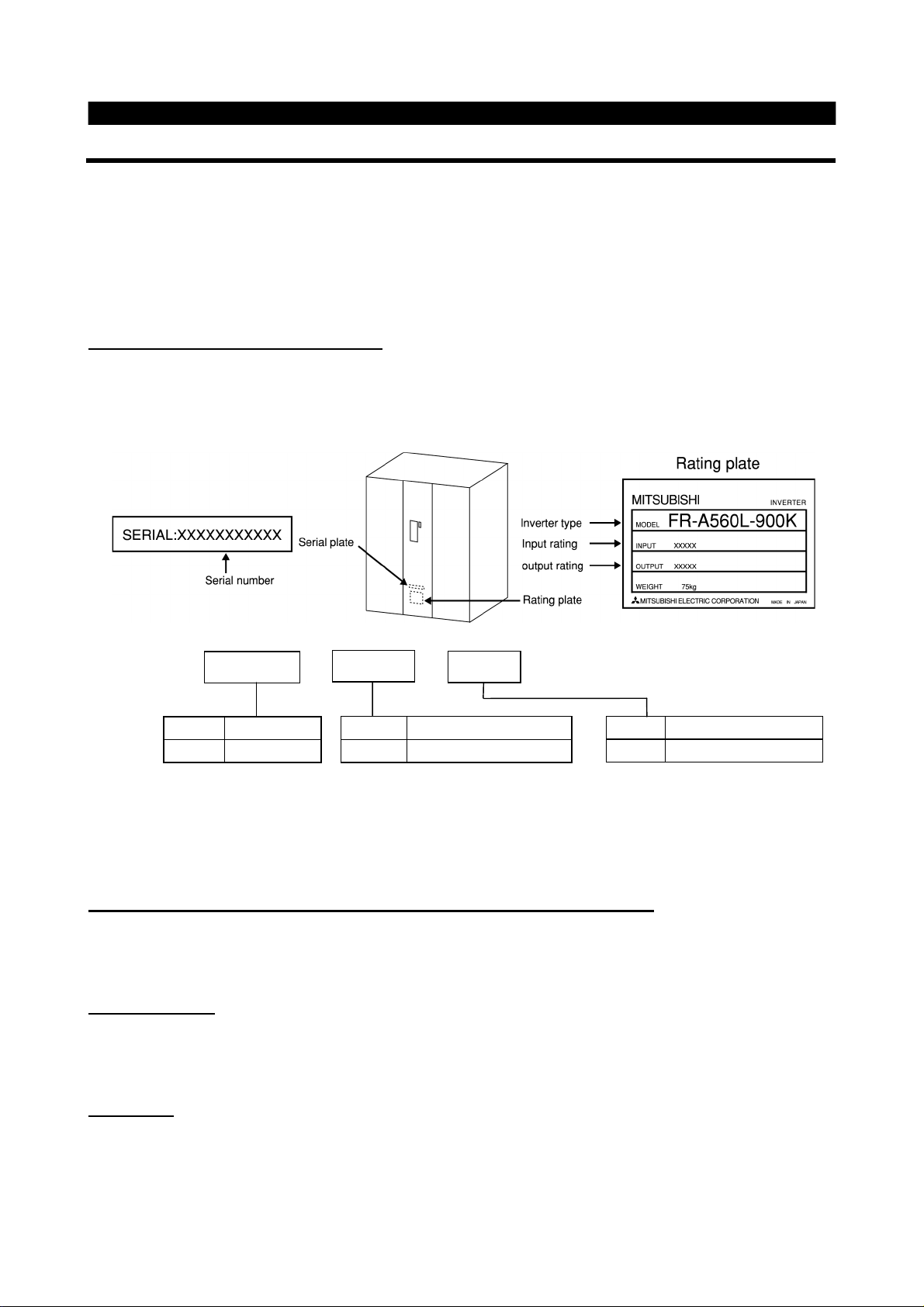
(1)
Unpacking and product check
Unpack the inverter and check the capacity plate on the front cover and the rating plate on the inverter side
face to ensure that the product agrees with your order and the inverter is intact
1) Inverter type
FR - A560L - 900K -
2) Accessory
Instruction manual
If you have found any discrepancy, damage, etc., please contact your sales representative.
(2)
Preparations of instruments and parts required for operation
Instruments and parts to be prepared depend on how the inverter is operated. Prepare equipment and parts
as necessary.
(3)
Installation
Symbol Voltage Class
A560L 600V class
Symbol Applicable Motor Capacity
900K Indicates capacity in “kW”
Symbol Specifications
NA U.S. specifications
To operate the inverter with high performance for a long time, install the inverter in a proper place, in a
correct direction, and with proper clearances.
(4)
Wiring
Connect the power supply, motor and operation signals (control signals) to the terminal block. Note that
incorrect connection may damage the inverter and peripheral devices. (See page 8.)
1
Page 9
1.2 Basic Configuration
E
OUTLIN
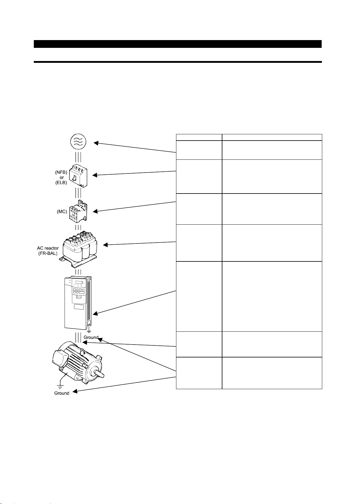
1.2.1 Basic configuration
The following devices are required to operate the inverter. Proper peripheral devices must be selected and
correct connections made to ensure proper operation. Incorrect system configuration and connections can
cause the inverter to operate improperly, its life to be reduced considerably, and in the worst case, the
inverter to be damaged.
Please handle the inverter properly in accordance with the information in each section as well as the
precautions and instructions of this manual. (For connections of the peripheral devices, refer to the
corresponding manuals.)
Name
Power supply
Earth leakage
circuit breaker
(ELB) or no-fuse
breaker (NFB)
Magnetic
contactor
Reactors
Use the power supply within the permissible
power supply specifications of the inverter.
The breaker should be selected with care
since a large inrush current flows in the
inverter at power on.
The breaker must have overcurrent
protection and earth leakage protection.
The magnetic contactor need not be
provided. When installed, do not use
it to start or stop the inverter. It might reduce
the inverter life.
The reactors must be used when the power
factor is to be improved or the inverter is
installed near a large power supply system
(ten times or more of Inverter Output, and
wiring distance within 10m (32.81 feet) ).
Make selection carefully.
Description
z
The inverter life is influenced by ambient
temperature. The ambient temperature
should be as low as possible within the
permissible range.
Inverter
Devices
connected to the
output
Ground
This must be noted especially when the
inverter is installed in an enclosure.
z
Incorrect wiring might lead to inverter
damage. The control signal lines must be
kept fully away from the main circuit to
protect them from noise.
Do not connect a power capacitor, surge
suppressor or radio noise filter to the output
side.
To prevent an electric shock, always ground
the motor and inverter.
2
Page 10

CHAPTER 2
INSTALLATION AND WIRING
This chapter gives information on the basic "installation and
wiring" of this product.
Always read the instructions in this chapter before using the
equipment.
2.1 Installation
2.2 Wiring
・・・・・・・・・・・・・・・・・・・・・・・・・・・・・・・・
・・・・・・・・・・・・・・・・・・・・・・・・・・・・・・・・・・・・
CHAPTER 1 OUTLINE
CHAPTER 2 INSTALLATION AND WIRING
CHAPTER 3 OPERATION
CHAPTER 4 PARAMETERS
3
5
CHAPTER 5 PROTECTIVE FUNCTIONS
CHAPTER 6 SPECIFICATIONS
APPENDICES
2
Page 11

2.1 Installation
INSTALLATION AND WIRING
2.1.1 Instructions for installation
1) Handle the unit carefully.
The inverter uses plastic parts. Handle it gently to protect it from damage. Also, hold the unit with even strength
and do not apply too much strength to the front cover alone.
2) Install the inverter where it is not subjected to vibration.
Note the vibration of a cart, press, etc.
3) Note on ambient temperature
The inverter life is under great influence of ambient temperature. In the place of installation, ambient temperature
must be within the permissible range (-10°C to +40°C (14°F to 104°F) ). Check that the ambient temperature is
within that range in the positions shown in figure 3).
*For FR-A560L-375, 450K at constant torque (CT) rating maximum ambient temperature can be 50°C (122°F).
4) Install the inverter on a non-combustible surface.
The inverter will be very hot (maximum. about 150°C (302°F) ). Install it on a non-combustible surface (e.g.
metal). Also leave sufficient clearances around the inverter.
5) Avoid high temperature and high humidity.
Avoid places where the inverter is subjected to direct sunlight, high temperature and high humidity.
Note: The cooling section outside the enclosure has the cooling fan. Do not use the inverter in any environment
where it is exposed to waterdrops, oil mist, dust, etc.
6) Avoid places where the inverter is exposed to oil mist, flammable gases, fluff, dust, dirt, etc.
Install the inverter in a clean place or inside a "totally enclosed" panel which does not accept any suspended
matter.
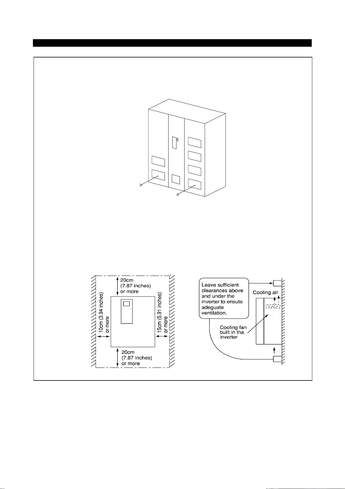
7) Note the cooling method when the inverter is installed in an enclosure.
When an inverter is mounted in an enclosure, the ventilation fans of the inverter and enclosure must be carefully
positioned to keep the ambient temperature of the inverter below the permissible value. If they are installed in
improper positions, the rise in ambient temperature will result in reduced performance of the inverter.
8) Secure the inverter vertically, with bolts.
Install the inverter on an installation surface securely and vertically with screws or bolts.
3
Page 12
3) Note on ambient temperatures
FR-A560L-530〜900K
FR-A560L-375, 450K
40°C at 5cm (1.97 inch)
INSTALLATION AND WIRING
4
Page 13
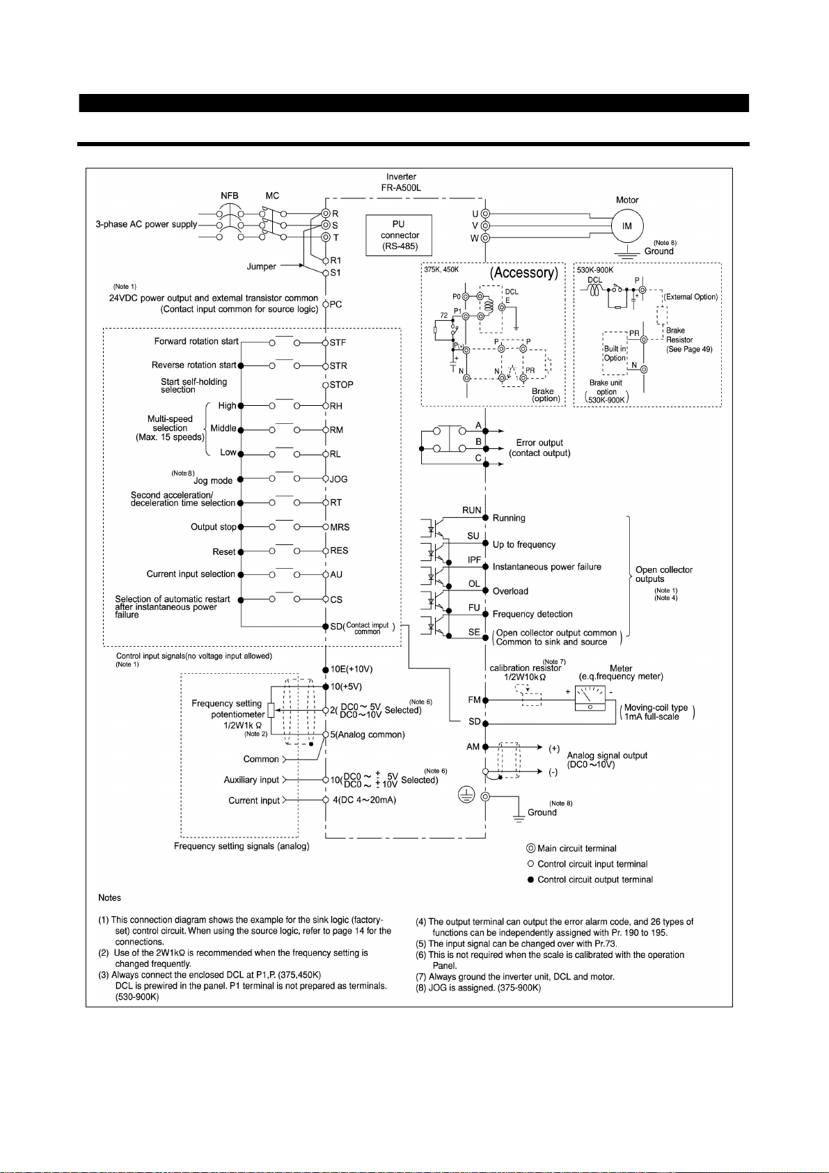
2.2 Wiring
2.2.1 Terminal connection diagram
INSTALLATION AND WIRING
5
Page 14
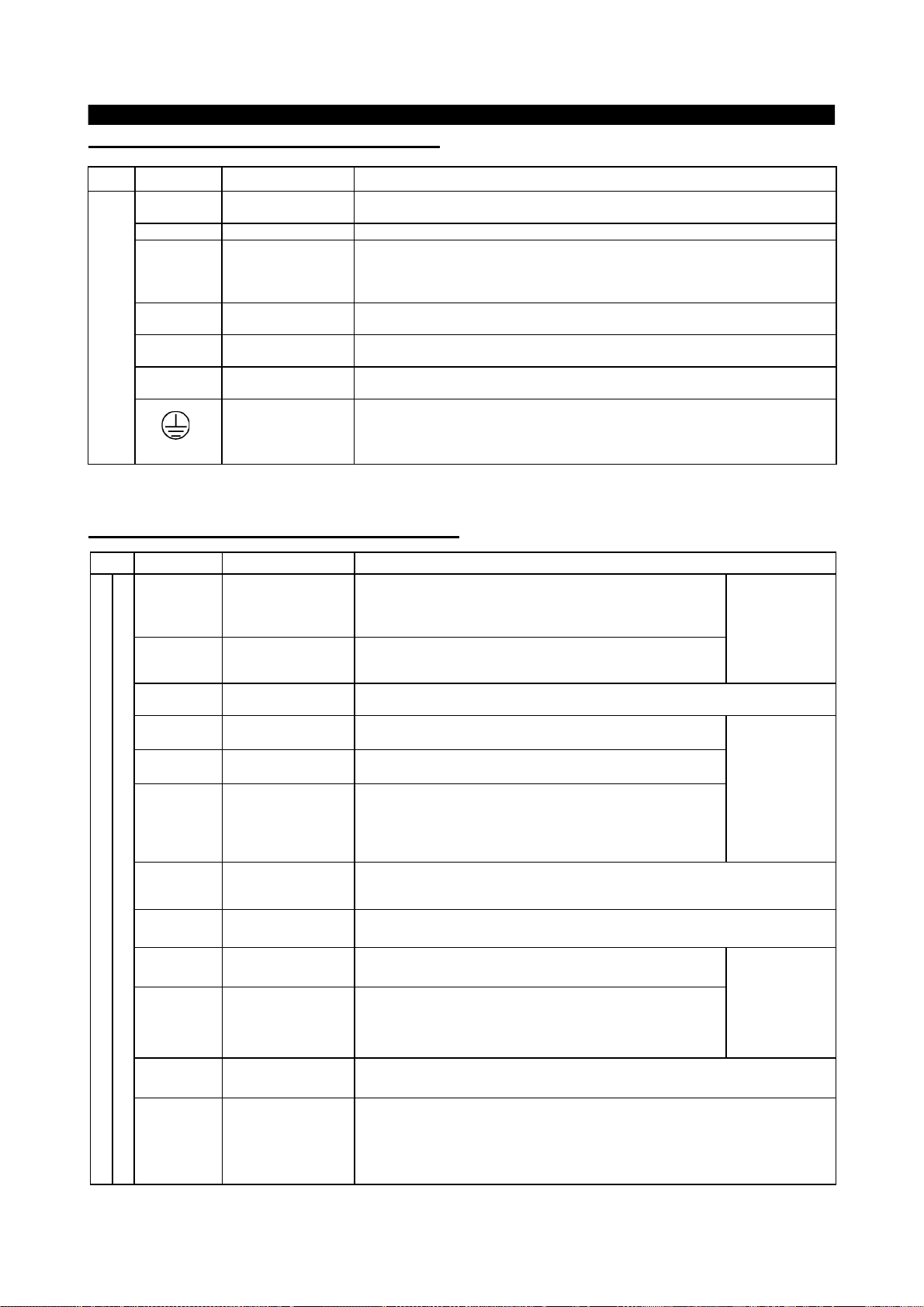
(1)
Description of main circuit terminals
INSTALLATION AND WIRING
Type
Main
circuit
Symbol
R, S, T
<L
, L2, L3>
1
U, V, W Inverter output Connect a three-phase squirrel-cage motor.
R1, S1
<L
, L21>
11
P, N
<+,->
P, P1
P, PR
<+, PR>
Terminal Name
AC power input
Power supply for
control circuit
Optional converter
connection
DC reactor
connection
Brake resistor
connection
Ground For grounding the inverter chassis. Must be earthed.
Connect to the commercial power supply. Keep these terminals unconnected when
using the high power factor converter (MT-HC).
Connected to the AC power supply terminals R and S. To retain the alarm display
and alarm output or when using the high power factor converter (MT-HC), remove
the jumpers from terminals R-R1 and S-S1 and apply external power to these
terminals.
Connect the optional power return converter (MT-RC) or high power factor converter
(MT-HC).
Connect the enclosed DC reactor. (375, 450K)
DC reactor is prewired in 530-900K sizes.
Connect the optional FR-BR5 brake resistor.
Description
Note:<>Terminal names in parentheses are those of the EC version.
(2)
Description of control circuit terminals
Type
Input signals
Symbol
STF Forward rotation start
STR Reverse rotation start
STOP
RH,RM,RL Multi-speed selection
(JOG) JOG mode selection
RT
MRS Output stop
RES Reset
AU
Contacts, e.g. start, function setting
CS
SD
PC
Terminal Name
Start self-holding
selection
Second acceleration/
deceleration time
selection
Current input
selection
Automatic restart after
instantaneous power
failure selection
Contact input
common (sink)
24VDC power and
external transistor
common
Contact input
common (source)
Turn on the STF signal to start forward rotation and turn it off to
stop. Acts as a programmed operation start signal in the
programmed operation mode. (Turn on to start and turn off to
stop.)
Turn on the STR signal to start reverse rotation and turn it off to
stop.
Turn on the STOP signal to select the self-holding of the start signal.
Use the RH, RM and RL signals as appropriate to select multiple
speeds.
This terminal connected internally, can not be used by the
customer. (530-900KW :this signal is assigned in Factory.)
Turn on the RT signal to select the second acceleration/
deceleration time. W hen the second functions such as "second
torque boost" and "second V/F (base frequency)" functions have
been set, these functions can also be selected by turning on the
RT signal.
Turn on the MRS signal (20ms or longer) to stop the inverter output.
Used to shut off the inverter output to bring the motor to a stop by the magnetic
brake.
Used to reset the protective circuit activated. Turn on the RES signal for more than
0.1 sec, then turn it off.
Only when the AU signal is turned on, the inverter can be
operated with the 4-20mADC frequency setting signal.
With the CS signal on, restart can be made automatically when
the power is restored after an instantaneous power failure. Note
that this operation requires restart parameters to be set. When
the inverter is shipped from the factory, it is set to disallow restart.
Common terminal for the terminal FM.
Common output terminal for 24VDC 0.1A power (PC terminal).
When transistor output (open collector output), such as a programmable controller, is
connected, connect the external power supply common for transistor output to this
terminal to prevent a fault caused by leakage current. This terminal can be used as a
24VDC, 0.1A power output. When source logic has been selected, this terminal
serves as a contact input common.
Description
When the STF
and STR signals
are turned on
simultaneously,
the stop
command is
given.
Input terminal
function selection
(Pr. 180 to
Pr. 186) change
terminal
functions.
Input terminal
function selection
(Pr. 180 to Pr.
186) change
terminal
functions.
6
Page 15

INSTALLATION AND WIRING
Type
Symbol
Terminal Name
Description
10E
10VDC, permissible load current
10mA10Frequency setting
power supply
5VDC, permissible load current
10mA
When the frequency setting potentiometer is
connected in the factory-set state, connect it to
terminal 10.
When it is connected to terminal 10E, change the
input specifications of terminal 2.
2
Frequency setting
(voltage)
By entering 0 to 5VDC (0 to 10VDC), the maximum output frequency is reached at
5V (or 10V) and I/O are proportional. Switch between input 0 to 5VDC (factory
setting) and 0 to 10VDC from operation terminal. Input resistance 10kΩ. Maximum
permissible voltage 20V.
4
Frequency setting
(current)
By entering 4 to 20mADC, the maximum output frequency is reached at 20mA and
I/O are proportional. This input signal is valid only when the AU signal is on. Input
resistance 250Ω. Maximum permissible current 30mA.
1
Auxiliary frequency
setting
By entering 0 to ±5VDC 0 to ±10VDC, this signal is added to the frequency setting
signal of terminal 2 or 4. Switch between input 0 to ±5VDC and 0 to ±10VDC
(factory setting) from operation terminal. Input resistance 10kΩ. Maximum
permissible voltage ±20V.
5
Frequency setting
input common
Common to the frequency setting signal (terminal 2, 1 or 4) and analog output
terminal AM. Do not earth.
A,B,C
Alarm output
Change-over contact output indicating that the output has been
stopped by the inverter protective function activated.
200VAC 0.3A, 30VDC 0.3A. Alarm: discontinuity across B-C
(continuity across A-C), normal: continuity across B-C
(discontinuity across A-C).
RUN
Inverter running
Switched low when the inverter output frequency is equal to or
higher than the starting frequency (factory set to 0.5Hz,
variable).
Switched high during stop or DC dynamic brake operation
Permissible load 24VDC 0.1A.
SU
Up to frequency
Switched low when the output frequency has reached within
±
10% of the set frequency (factory setting, variable). Switched
high during acceleration, deceleration or stop
. Permissible
load 24VDC 0.1A.
OL
Overload alarm
Switched low when the stall prevention function has caused
stall prevention to be activated. Switched high when stall
prevention is reset
. Permissible load 24VDC 0.1A.
IPF
Instantaneous power
failure
Switched low when instantaneous power failure or
undervoltage protection is activated
. Permissible load
24VDC 0.1A.
FU
Frequency detection
Switched low when the output frequency has reached or
exceeded the detection frequency set as appropriate. Switched
high when below the detection frequency
. Permissible load
24VDC 0.1A
Output terminal
function selection
(Pr. 190 to Pr.
195) change
terminal
functions.
SE
Open collector output
common
Common to the RUN, SU, OL, IPF and FU terminals.
FM
For meter
Factory setting of output item:
Frequency
Permissible load current 1mA
1440 pulses/second. at 60Hz
AM
Analog signal output
One selected from 16 monitoring
items, such as output
frequency, is output
.
The output signal is proportional
to the magnitude of each
monitoring item.
Factory setting of output item:
Frequency
Output signal 0 to 10VDC
Permissible load current 1mA
PU connector
With the operation panel connector, communication can be made through RS-485.
·
Conforming Standard : EIA Standard RS-485
·
Transmission format : Multi-drop link
·
Communication speed : Maximum 19200 baud rates
·
Overall length : 500m
Input signals
Analog frequency setting
Contact
Open collector
Output signals
Pulse
Analog
(note1)
(note 1)
(note 1)
(note 1)
(note 1)
(note 2)
RS485
Communication
Note1: Low indicates that the open collector outputting transistor is on (conducts). High indicates that the
transistor is off (does not conduct).
Note2: Not output while the inverter is reset.
7
Page 16

INSTALLATION AND WIRING
2.2.2 Wiring of the main circuit
(1)
Wiring instructions
1) Power must not be applied to the output terminals (U, V, W) of the inverter. Otherwise the inverter will be
damaged.
2) After wiring, wire off-cuts must not be left in the inverter.
Wire off-cuts can cause an alarm, failure or malfunction. Always keep the inverter clean.
3) Use thick cables to make a voltage drop of 2% or less.
If the wiring distance is long between the inverter and motor, a main circuit cable voltage drop will cause the
motor torque to decrease especially at the output of a low frequency.
4) Electromagnetic wave interference
The input/output (main circuit) of the inverter includes harmonic components, which may interfere with the
communication devices (such as AM radios) used near the inverter. In this case, use shielded wire cables as
the power cable.
5) Do not install a power capacitor, surge suppressor or radio noise filter (FR-BIF option) in the output side of the
inverter.
This will cause the inverter to trip or the capacitor and surge suppressor to be damaged. If any of the above
devices are installed, immediately remove them.
6) When rewiring after operation, make sure that the POWER lamp has gone off, and when more than 10minutes
have elapsed after power-off, check with a tester that the DC bus voltage is zero. After that, start rewiring work.
For some time after power-off, there is a dangerous voltage in the capacitor.
7) Top attachments should be removed before operating because of Air exhaust. Side attachments can be used
for fixing the unit. (See page 44)
Notes on Grounding
• Leakage currents flow in the inverter. To prevent an electric shock, the inverter and motor must be grounded
(grounding resistance: 10Ω or less.)
• Use the dedicated ground terminal to ground the inverter. (Do not use the screw in the case, chassis, etc.)
• The ground cable should have a thickness of 38mm2, or more, and be as short as possible. The grounding
point should be as close to the inverter as possible.
8
Page 17
INSTALLATION AND WIRING
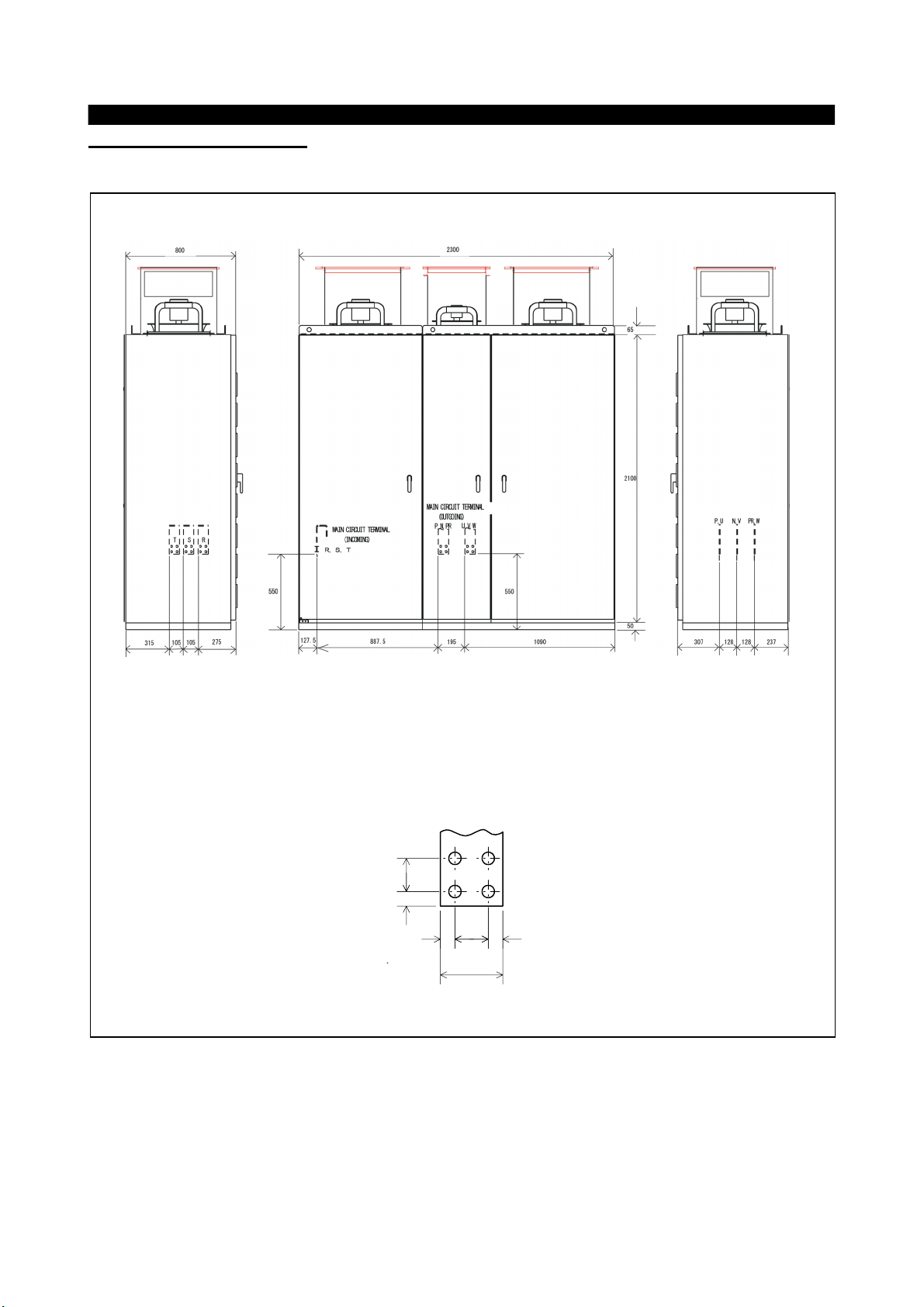
(2)
Terminal block layout
In the main circuit of the inverter, the terminals are arranged as shown below:
FR-A560L-530K〜900K
Left Side
MAIN CIRCUIT TERMINAL (Detail)
40
17.5
Front
4017.5 17.5
75
Right Side
Units
<mm>
9
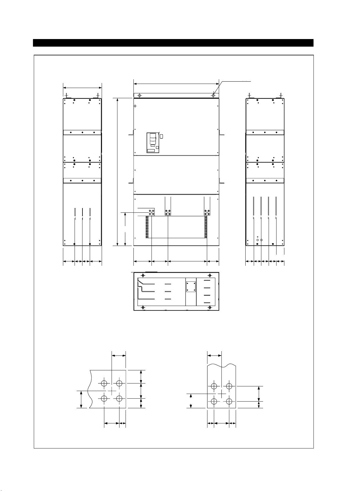
Page 18
)
)
FR-A560L-375K, 450K
500
TSR
P1 N P
1900
INSTALLATION AND WIRING
1100
Rg[ pl
4‑φ 30
4 - 30
P0WVU
1569696152
R, S, T
TERMINAL (Detail
[q
45
430
37.5
35
40
35
230
505210
P
R
N
S
P1
T
P0
155
U
V
W
108 96 96 96 104
(Bottom View)
U, V, W, P0
P1, P, N
[q
TERMINAL (Detail
40
40
37.5
17.5
40
17.5
Units<mm
17.517.5 40
>
10
Page 19
INSTALLATION AND WIRING
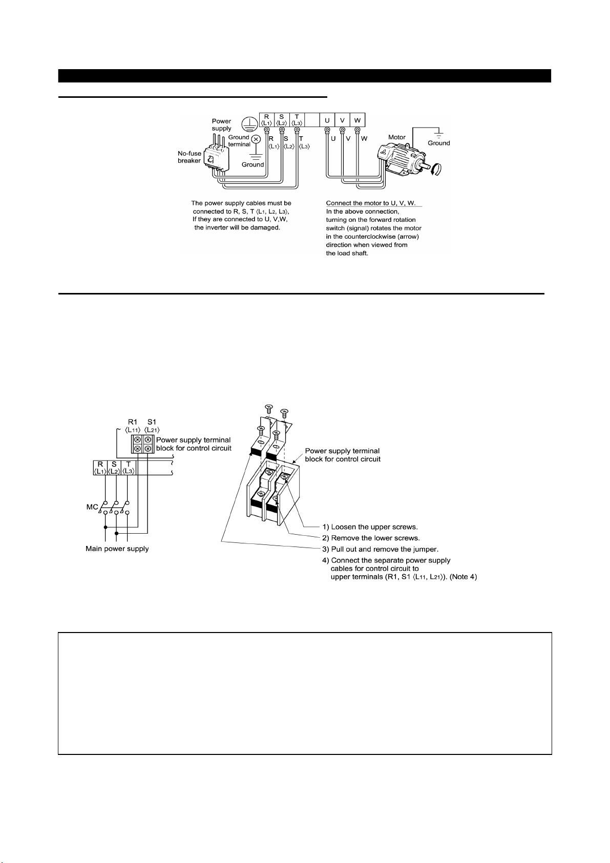
(3)
Connection of the power supply and motor
(4)
Connecting the control circuit to a power supply separately from the main circuit
If the magnetic contactor (MC) in the inverter power supply is opened when the protective circuit is operated,
the inverter control circuit power is lost and the alarm output signal cannot be kept on. To keep the alarm
signal on terminals R1 and S1 are available. In this case, connect the power supply terminals R1 and S1 <L
and L
> of the control circuit to the primary side of the MC.
21
<Connection procedure>
11
Note: 1. W hen the main circuit power (R, S, T) <L
(terminals R1, S1<L
2. W hen using a separate power supply, the jumpers across R-R1 and S-S1 <L
L
>must be removed. Otherwise the inverter may be damaged.
2-L21
3. For a different power supply system which takes the power of the control circuit from other than
the primary side of the MC, the voltage should be equal to the main circuit voltage.
4. The power supply cables must not be connected to the lower terminals. If connected, the inverter
may be damaged.
, L21>). Otherwise the inverter may be damaged.
11
, L2, L3,> is on, do not switch off the control power
1
and
1-L11
11
Page 20
INSTALLATION AND WIRING
2.2.3 Wiring of the control circuit
(1)
Wiring instructions
1) Terminals SD, SE and 5 are common to the I/O signals and isolated from each other. These common terminals
must not be connected to each other or earthed.
2) Use shielded or twisted cables for connection to the control circuit terminals and run them away from the main
and power circuits (including the 200V relay sequence circuit).
3) The frequency input signals to the control circuit are micro currents. When contacts are required, use two or
more parallel micro signal contacts or a twin contact to prevent a contact fault.
4) It is recommended to use the cables of 0.75mm2 gauge for connection to the control circuit terminals.
If the cable gauge used is 1.25mm2 or more, the front cover may be lifted when there are many cables running
or the cables are run improperly, resulting in an operation panel or parameter unit contact fault.
(2)
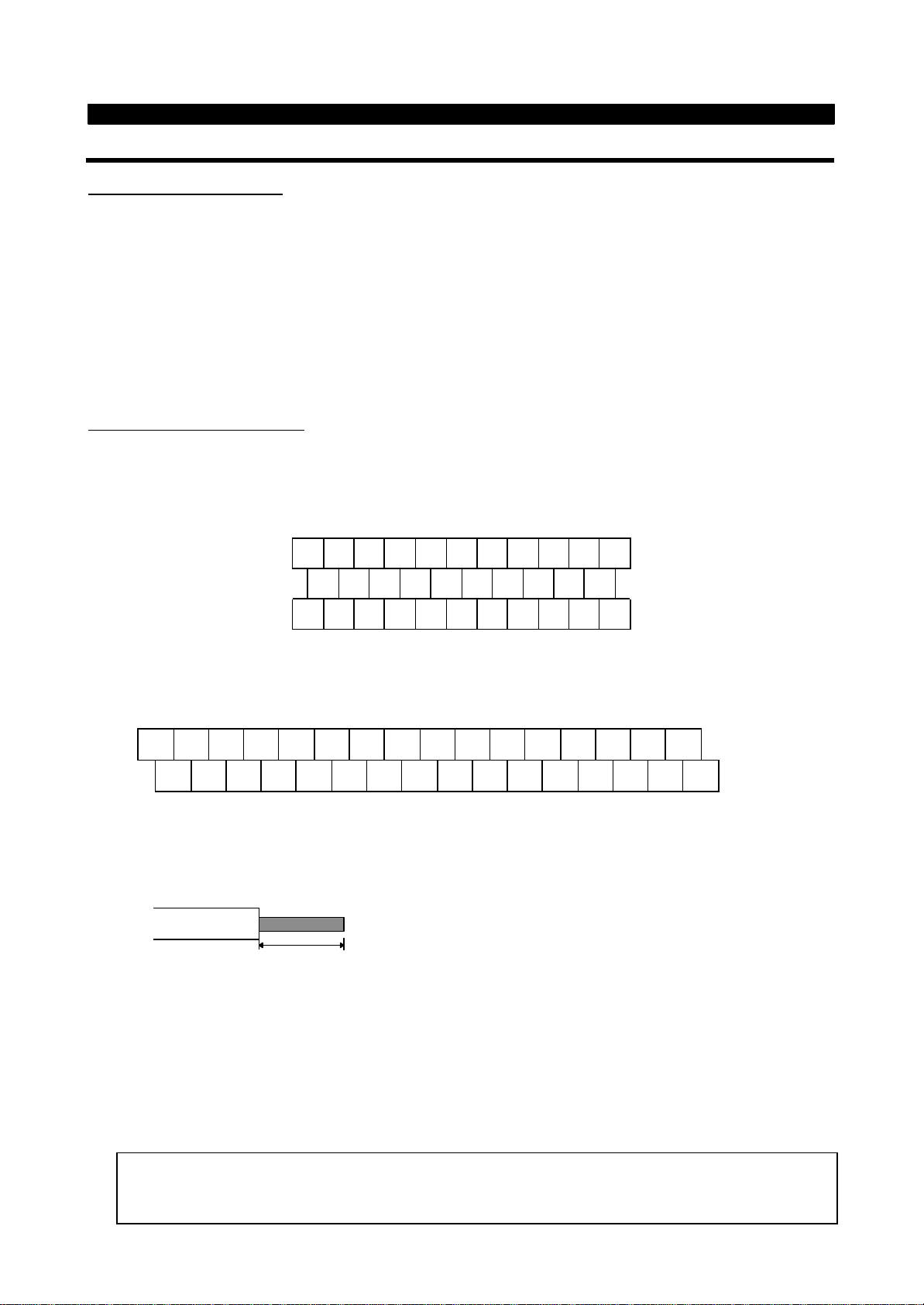
Terminal block layout
l
NA version(OR Version
In the control circuit of the inverter, the terminals are arranged as shown below:
Terminal screw size: M3.5
)
A
B C PC AM 10 E 1 0 2 5 4 1
RL
RM RH RT AU STOP MRS RES SD FM
SE RUN SU IPF OL FU SD STF STR JOG CS
l
EC version
Terminal screw size : M3
A B C SD AM 10E 10 2 5 4 1 RL RM RH RT AU
SE RUN SU LPF OL FU STOP MRS RES PC STF STR JOG CS FM SD
<Wiring procedure>
1) For the wiring of the control circuit, strip the sheaths of the cables and use them as they are.
Strip the sheath to the following dimension. If too much is stripped this may cause a short circuit with
the neighboring cable. If too little stripped this may cause cable disconnection.
6mm ± 1mm
2) Loosen the terminal screw and insert the cable into the terminal.
3) Tighten the screw to the specified torque.
Undertigthening can cause cable disconnection or malfunction. Overtightening can cause a short circuit or
malfunction due to the screw or unit damaged.
Tightening torque : 5 to 6 kgf・cm
Note : Wire the stripped cable by twisting it to prevent it from becoming loose. (Do not plate the cable with
solder.)
Note : 1. Use a NFB (No fuse breakers) or fuse on the inverter input (primary) side.
2. Make sure that the control circuit terminal wiring does not touch power circuit terminals (or
screws) or conducting power circuit.
12
Page 21

INSTALLATION AND WIRING
(3)
Changing the control logic
The input signals are set to sink logic for the NA version, and to source logic for the EC version.
To change the control logic, the connector on the back of the control circuit terminal block must be moved to
the other position.
(The output signals may be used in either the sink or source logic independently of the connector position.)
1) Loosen the two mounting screws in both ends of the control circuit terminal block. (The screws cannot be
removed.)
With both hands, pull down the terminal block from the back of the control circuit terminals.
2) Remove the connector in the sink logic position on the back surface of the control circuit terminal block
and fit it to the source logic position.
3) Using care not to bend the pins of the control circuit connector, reinstall the control circuit terminal block
and fix it with the mounting screws.
Note: 1. Make sure that the control circuit connector is fitted correctly.
2. While power is on, never disconnect the control circuit terminal block.
3. The sink-source logic change-over connector must be fitted in only one of those positions. If it is
fitted in both positions at the same time, the inverter may be damaged.
13
Page 22

INSTALLATION AND WIRING
4) Sink logic type
• In this logic, a signal switches on when a current flows out of the corresponding signal input terminal.
Terminal SD is common to the contact input signals. Terminal SE is common to the open collector
output signals.
AX40
RUN
SU
SE
DC24V
Current
R
STF
R
STR
SD
• When using an external power supply for transistor output, use terminal PC as a common to prevent
misoperation caused by leakage current. (Do not connect terminal SD of the inverter with terminal 0V of
the external power supply.)
STF
STR
RH
RM
RL
RES
PC
SD
Inverter
DC24V
(SD)
AY40 type
transistor ou tput
module
1
2
3
4
5
6
9
10
DC24V
1
2
9
R
R
R
R
8
14
Page 23

INSTALLATION AND WIRING
5) Source logic type
• In this logic, a signal switches on when a current flows into the corresponding signal input terminal.
Terminal PC is common to the contact input signals. Terminal SE is common to the open collector
output signals.
PC
Current
STF
STR
R
R
• When using an external power supply for transistor output, use terminal SD as a common to prevent
misoperation caused by leakage current.
SE
RUN
SU
DC24V
AX80
1
2
8
9
R
R
R
R
DC24V
PC
STF
STR
SD
Inverter
DC24V
(SD)
AY-80
9
1
2
10
(4)
How to use terminals “STOP”, “CS” and “PC”
1) Using the “STOP” terminal
A connection example (for sink logic) for self-holding the start signal (forward
rotation, reverse rotation) is shown on the right.
2) Using the “CS” terminal
This terminal is used to perform automatic restart after instantaneous power failure
and commercial power supply-inverter switch-over operation.
<Example: Automatic restart after instantaneous power failure in sink logic>
Connect terminals CS-SD and set a value other than “9999” in Pr. 57 “coasting time
for automatic restart after instantaneous power failure”.
3) Using the “PC” terminal
This terminal can be used as 24VDC power output using SD as a common terminal.
Specifications: 18V to 26VDC, 0.1A permissible current
Note that the wiring length should be within 30m.
Do not short terminals PC-SD.
When terminal PC is used as a 24V power supply, leakage current from transistor
output cannot be prevented.
STOP
Stop
Forward
rotation
Reverse
rotation
CS SD
(Short)
MRS
RES
SD
STF
STR
15
Page 24

A
B
INSTALLATION AND WIRING
2.2.4 Connection to the PU connector
(1)
When connecting the operation panel or parameter unit using a connection
cable
<Recommended cable connector>
• Parameter unit connection cable (FR-CB2) (option) or the following connector and cable.
• Connector: RJ45 connector
Example: 5-554720-3, Nippon AMP
• Cable: Cable conforming to EIA568 (e.g. 10BASE-T cable)
Example: SGLPEV 0.5mm×4P, MITSUBISHI CABLE INDUSTRIES, LTD.
Note: The maximum wiring length is 20m (65.62 feet).
(2)
For RS-485 communication
With the operation panel disconnected, the PU connector can be used for communication operation from a
personal computer etc.
<PU connector pin-outs>
Viewed from the inverter (receptacle side) front
①
⑧
①
②
③
④
SG
P5S
RDA
SDB
⑤
⑥
⑦
⑧
SD
RD
SG
P5S
Note: 1. Do not connect the PU connector to the computer’s LAN board, FAX modem socket or
telephone modular connector. Otherwise, the product may be damaged due to electrical
specification differences.
2. Pins 2 and 8 (P5S) provide power to the operation unit or parameter unit. Do not use these pins
for RS-485 communication.
Use the connector and cable as detailed below.
• Connector: RJ45 connector
Example: 5-554720-3, Nippon AMP
• Cable: Cable conforming to EIA568 (e.g. 10BASE-T cable)
Example: SGLPEV 0.5mm×4P, MITSUBISHI CABLE INDUSTRIES, LTD.
When the communication board of the personal computer has the RS-232C specifications, prepare an
RS-485, RS-232C converter.
Example of converter.
1) Model: FA-T-RS40
Converter
Industrial Systems Division Mitsubishi Electric Engineering Co., Ltd.
2) Model: DINV-485CAB
Interface built-in cable
Dia Trend Co., Ltd.
16
Page 25

L
INSTALLATION AND WIRING
2.2.5 Design information
1) For commercial power supply-inverter switch-over operation, provide electrical and mechanical interlocks
for MC1 and MC2 designed for commercial power supply-inverter switch-over.
When there is a commercial power supply-inverter switch-over circuit as shown below, the inverter will be
damaged by leakage current from the power supply due to arcs generated at the time of switch-over or
chattering caused by a sequence error.
2) If the machine must not be restarted when power is restored after a power failure, provide a magnetic
contactor in the inverter’s primary circuit and also make up a sequence which will not switch on the start
signal.
If the start signal (start switch) remains on after a power failure, the inverter will automatically restart as
soon as the power is restored.
3) When the power supply used with the control circuit is different from the one used with the main circuit,
make up a circuit which will switch off the main circuit power supply terminals R, S, T<L
power supply terminals , R1, S1<L
, L21> for the control circuit are switched off.
11
4) Since the input signals to the control circuit are on a low level, use two parallel micro signal contacts or a
twin contact for contact inputs to prevent a contact fault.
5) Do not apply a large voltage to the contact input terminals (e.g. STF) of the control circuit.
6) Do not apply a voltage directly to the alarm output signal terminals (A, B, C).
Always apply a voltage to these terminals via a relay coil, lamp, etc.
7) Make sure that the specifications and rating match the system requirements.
1) Commercial power supply-inverter switch-over
MC1
Interlock
2) Low-level signal contacts
, L2, L3 > when the
1
Inverter
U
V
W
MC2
Sneak current
IM
ow-level signal contacts
Twin contact
Power
supply
R, <L1>
S, <L2>
T, <L3>
17
Page 26

CHAPTER 3
OPERATION
This chapter provides the basic "operation" information for
use of this product.
Always read this chapter before using the equipment.
3.1 Pre-Operation Information
3.2 Operation
・・・・・・・・・・・・・・・・・・・・・・
・・・・・・・・
Refer to FR-A540L/A560L
Refer to FR-A540L/A560L
CHAPTER 1 OUTLINE
CHAPTER 2 INSTALLATION AND WIRING
CHAPTER 3 OPERATION
CHAPTER 4 PARAMETERS
CHAPTER 5 PROTECTIVE FUNCTIONS
CHAPTER 6 SPECIFICATIONS
APPENDICES
3
Page 27

CHAPTER 4
PARAMETERS
This chapter explains the "parameters" of this product.
Always read the instructions before using the equipment.
4.1 Parameter List
4.2 Parameter Function Details
Note: By making parameter settings, you can change the functions of contact input
terminals RL, RM, RH, RT, AU, CS and open collector output terminals RUN, SU,
IPF, OL, FU. Therefore, signal nam es cor responding to the functions are used in
the description of this chapter (except in the wiring exam ples). Note that they are
not terminal names.
The setting in brackets refer to the “EC” versions default settings.
・・・・・・・・・・・・・・・・・・
・・・・・・・
18
Refer to FR-A540L/A560L
CHAPTER 1 OUTLINE
CHAPTER 2 INSTALLATION AND WIRING
CHAPTER 3 OPERATION
CHAPTER 4 PARAMETERS
CHAPTER 5 PROTECTIVE FUNCTIONS
CHAPTER 6 SPECIFICATIONS
APPENDICES
4
Page 28

4.1 Parameter List
PARAMETERS
Minimum
Setting
Increments
0
Torque boost (Note 1)
0 to 30%
0.1%
1%
481Maximum frequency
0 to 60Hz
0.01Hz
60Hz
492Minimum frequency
0 to 120Hz
0.01Hz
0Hz
493Base frequency
0 to 400Hz
0.01Hz
60Hz<50Hz>
504Multi-speed setting (high speed)
0 to 400Hz
0.01Hz
60Hz
515Multi-speed setting (middle speed)
0 to 400Hz
0.01Hz
30Hz
516Multi-speed setting (low speed)
0 to 400Hz
0.01Hz
10Hz
517Acceleration time
0 to 3600 sec/
0 to 360 sec
0.1 sec/
0.01 sec
15 sec
528Deceleration time
0 to 3600 sec/
0 to 360 sec
0.1 sec/
0.01 sec
15 sec
52
9
Electronic thermal O/L relay
0 to 3600A
0.1A
Rated output cur-
rent
5210DC injection brake operation frequency
0 to 120Hz, 9999
0.01Hz
3Hz
5411DC injection brake operation time
0 to 10 sec, 8888
0.1 sec
0.5 sec
5412DC injection brake voltage
0 to 30%
0.1%
1%
5413Starting frequency
0 to 60Hz
0.01Hz
0.5Hz
5514Load pattern selection (Note 1)
0 to 510
5515Jog frequency
0 to 400Hz
0.01Hz
5Hz
5616Jog acceleration/deceleration time
0 to 3600 sec/
0 to 360 sec
0.1 sec/
0.01 sec
0.5 sec
5617MRS input selection
0,210
5718High-speed maximum frequency
0 to 400Hz
0.01Hz
60Hz
5719Base frequency voltage (Note 1)
0 to 1000V, 8888, 9999
0.1V
9999<8888>
5720Acceleration/deceleration reference
frequency
1 to 400Hz
0.01Hz
60Hz<50Hz>
5721Acceleration/deceleration time
increments
0,110
57
*22
Stall prevention operation level
0 to 150%, 9999
0.1%
150%
58
*23
Stall prevention operation level at
double speed
0 to 150%, 9999
0.1%
9999
5824Multi-speed setting (speed 4)
0 to 400Hz, 9999
0.01Hz
9999
5925Multi-speed setting (speed 5)
0 to 400Hz, 9999
0.01Hz
9999
5926Multi-speed setting (speed 6)
0 to 400Hz, 9999
0.01Hz
9999
5927Multi-speed setting (speed 7)
0 to 400Hz, 9999
0.01Hz
9999
5928Multi-speed input compensation
0, 110
5929Acceleration/deceleration pattern
0, 1, 2, 3
1
0
6030Regenerative function selection
0, 1, 2
1
0
6131Frequency jump 1A
0 to 400Hz, 9999
0.01Hz
9999
6232Frequency jump 1B
0 to 400Hz, 9999
0.01Hz
9999
6233Frequency jump 2A
0 to 400Hz, 9999
0.01Hz
9999
6234Frequency jump 2B
0 to 400Hz, 9999
0.01Hz
9999
6235Frequency jump 3A
0 to 400Hz, 9999
0.01Hz
9999
6236Frequency jump 3B
0 to 400Hz, 9999
0.01Hz
9999
62
37
Speed display
0,1 to 9998
1
0
6341Up-to-frequency sensitivity
0 to 100%
0.1%
10%
6442Output frequency detection
0 to 400Hz
0.01Hz
6Hz
64
43
Output frequency detection for reverse
rotation
0 to 400Hz, 9999
0.01Hz
9999
6444Second acceleration/deceleration time
0 to 3600 sec/
0 to 360 sec
0.1 sec/
0.01 sec
5 sec
6545Second deceleration time
0 to 3600 sec/
0 to 360 sec, 9999
0.1 sec/
0.01 sec
9999
6546Second torque boost (Note 1)
0 to 30%, 9999
0.1%
9999
6547Second V/F (base frequency) (Note 1)
0 to 400Hz, 9999
0.01Hz
9999
65
*48
Second stall prevention operation
current
0 to 150%
0.1%
150%
6549Second stall prevention operation
frequency
0 to 400Hz, 9999
0.01Hz
0
65
50
Second output frequency detection
0 to 400Hz
0.01Hz
30Hz
64
PARAMETER
Func-
tion
Parameter
Number
Basic functions
Name Setting Range
Factory Setting
Refer To
Page:
<Note9>
Standard operation functions
Output
terminal
functions
Second functions
18
Page 29

PARAMETERS
Minimum
Setting
Increments
52
DU/PU main display data selection
0, 5 to 14, 17, 18, 20,
23, 24, 25, 100
1
0
6753PU level display data selection
0 to 3, 5 to 14, 17, 18
1
1
6754FM terminal function selection
1 to 3, 5 to 14,
17, 18, 21
1
1
6755Frequency monitoring reference
0 to 400Hz
0.01Hz
60Hz<50Hz>
69
56
Current monitoring reference
0 to 3600A
0.1A
Rated output
current
6957Restart coasting time
0 to 30 sec, 9999
0.1 sec
9999
70
58
Restart cushion time
0 to 60 sec
0.1 sec
1.0 sec
70
59
Remote setting function selection
0, 1, 2
1
0
7260Intelligent mode selection
0 to 810
7361Reference I for intelligent mode
0 to 3600A, 9999
0.1A
9999
75
*62
Ref. I for intelligent mode accel.
0 to 150%, 9999
0.1%
9999
75
*63
Ref. I for intelligent mode decel.
0 to 150%, 9999
0.1%
9999
7564Starting frequency for elevator mode
0 to 10Hz, 9999
0.01Hz
9999
7565Retry selection
0 to 510
7666Stall prevention operation level
reduction starting frequency
0 to 400Hz
0.01Hz
60Hz<50Hz>
7767Number of retries at alarm occurrence
0 to 10,101 to 110
1
0
7668Retry waiting time
0 to 10 sec
0.1 sec
1 sec
7669Retry count display erasure
00
7670Special regenerative brake duty
0 to 100%
0.1%
0%
7771Applied motor
0 to 8, 13 to 18
1
0
7872PWM frequency selection
0, 1, 2
1
1
79730-5V/0-10V selection
0 to 5, 10 to 15
1
1
8074Filter time constant
0 to 811
8175Reset selection/disconnected PU
detection/PU stop selection
0 to 3, 14 to 17
1
14
8176Alarm code output selection
0, 1, 2, 3
1
0
8377Parameter write disable selection
0, 1, 2
1
0
8478Reverse rotation prevention selection
0, 1, 2
1
0
85
79
Operation mode selection
0 to 810
8680Motor capacity
0 to 3600kW, 9999
0.1kW
9999
8981Number of motor poles
2, 4, 6, 12, 14, 16, 9999
1
9999
8982Motor exciting current (Note 6)
0 to , 9999
1
9999
90
*83
Rated motor voltage
0 to 1000V
0.1V
575V
9084Rated motor frequency
50 to 120Hz
0.01Hz
60Hz<50Hz>
9089Speed control gain
0 to 200%
0.1%
100%
8990Motor constant (R1) (Note 6)
(Note 6)
(Note 6)
9999
9091Motor constant (R2) (Note 6)
(Note 6)
(Note 6)
9999
9092Motor constant (L1) (Note 6)
(Note 6)
(Note 6)
9999
9093Motor constant (L2) (Note 6)
(Note 6)
(Note 6)
9999
9094Motor constant (X) (Note 6)
(Note 6)
(Note 6)
9999
9095Online auto tuning selection
0, 110
96
96
Auto tuning setting/status
0, 1, 101
1
0
90
100
V/F1 (first frequency) (Note 1)
0 to 400Hz, 9999
0.01Hz
9999
98
101
V/F1 (first frequency voltage)
(Note 1)
0 to 1000V
0.1V
0
98
102
V/F2 (second frequency) (Note 1)
0 to 400Hz, 9999
0.01Hz
9999
98
103
V/F2 (second frequency voltage)
(Note 1)
0 to 1000V
0.1V
0
98
104
V/F3 (third frequency) (Note 1)
0 to 400Hz, 9999
0.01Hz
9999
98
105
V/F3 (third frequency voltage) (Note 1)
0 to 1000V
0.1V
0
98
106
V/F4 (fourth frequency) (Note 1)
0 to 400Hz, 9999
0.01Hz
9999
98
Func-
Parameter
tion
Automatic
Number
Display functions
restart
functions
function
Additional
Name Setting Range
Factory Setting
Refer To
Page:
<Note9>
Operation selection functions
Motor constants
characteristics
5-point flexible V/F
19
Page 30

Minimum
Setting
Increments
107
V/F4 (fourth frequency voltage)
(Note 1)
0 to 1000V
0.1V
0
98
108
V/F5 (fifth frequency) (Note 1)
0 to 400Hz, 9999
0.01Hz
9999
98
109
V/F5 (fifth frequency voltage)
(Note 1)
0 to 1000V
0.1V
0
98
110
Third acceleration/deceleration time
0 to 3600 sec/
0 to 360 sec, 9999
0.1 sec/
0.01 sec
9999
99
111
Third deceleration time
0 to 3600 sec/
0 to 360 sec, 9999
0.1 sec/
0.01 sec
9999
99
112
Third torque boost (Note 1)
0 to 30.0%, 9999
0.1%
9999
99
113
Third V/F (base frequency) (Note 1)
0 to 400Hz, 9999
0.01Hz
9999
99
*114
Third stall prevention operation current
0 to 150%
0.1%
150%
99
115
Third stall prevention operation
frequency
0 to 400Hz
0.01Hz
0
99
116
Third output frequency detection
0 to 400Hz, 9999
0.01Hz
9999
99
117
Station number
0 to 31
1
0
99
118
Communication speed
48, 96, 192
1
192
99
119
Stop bit length/data length
0, 1 (data length 8)
10, 11 (data length 7)
1
1
99
120
Parity check presence/absence
0, 1, 2
1
2
99
121
Number of communication retries
0 to 10, 9999
1
1
99
122
Communication check time interval
0, 0.1 to 999.8 sec,
9999
0.1
0<9999>
99
123
Waiting time setting
0 to 150ms, 9999
10ms
9999
99
124
CR, LF presence/absence selection
0,1,211
99
128
PID action selection
10, 11, 20, 21
1
10
109
129
PID proportional band
0.1 to 1000%, 9999
0.1%
100%
109
130
PID integral time
0.1 to 3600 sec, 9999
0.1 sec
1 sec
109
131
Upper limit
0 to 100%, 9999
0.1%
9999
109
132
Lower limit
0 to 100%, 9999
0.1%
9999
109
133
PID action set point for PU operation
0 to 100%
0.01%
0%
109
134
PID differential time
0.01 to 10.00 sec, 9999
0.01 sec
9999
109
135
Commercial power supply-inverter
switch-over sequence output terminal
selection
0, 1, 2
1
0
116
136
MC switch-over interlock time
0 to 100.0 sec
0.1 sec
1.0 sec
116
137
Start waiting time
0 to 100.0 sec
0.1 sec
0.5 sec
116
138
Commercial power supply-inverter
switch-over selection at alarm
occurrence
0, 110
116
139
Automatic inverter-commercial power
supply switch-over frequency
0 to 60.00Hz, 9999
0.01Hz
9999
116
140
Backlash acceleration stopping
frequency (Note 7)
0 to 400Hz
0.01Hz
1.00Hz
119
141
Backlash acceleration stopping time
(Note 7)
0 to 360 sec
0.1 sec
0.5 sec
119
142
Backlash deceleration stopping
frequency (Note 7)
0 to 400Hz
0.01Hz
1.00Hz
119
143
Backlash deceleration stopping time
(Note 7)
0 to 360 sec
0.1 sec
0.5 sec
119
144
Speed setting switch-over
0, 2, 4, 6, 8, 10, 102,
104, 106, 108, 110
1
4
119
*148
Stall prevention level at 0V input
0 to 150%
0.1%
120%
58
*149
Stall prevention level at 10V input
0 to 150%
0.1%
150%
58
PARAMETERS
Func-
Parameter
tion
Number
characteristics
5-point flexible V/F
Third functions
Name Setting Range
Factory Setting
Refer To
Page:
<Note9>
Communication functions
PID control
inverter switch-over
Commercial power supply-
Backlash
Display
functions
Additional
20
Page 31

PARAMETERS
Minimum
Setting
Increments
150
Output current detection level
0 to 200%
0.1%
150%
120
151
Output current detection period
0 to 10 sec
0.1 sec
0
120
152
Zero current detection level
0 to 200%
0.1%
5.0%
121
153
Zero current detection period
0 to 1 sec
0.01 sec
0.5 sec
121
154
Voltage reduction selection during stall
prevention operation
0, 111
121
155
RT activated condition
0, 1010
122
*156
Stall prevention operation selection
0 to 31 (Odd), 100
1
0
122
157
OL signal waiting time
0 to 25 sec, 9999
0.1 sec
0
124
158
AM terminal function selection
1 to 3, 5 to 14,
17, 18, 21
1
1
124
160
User group read selection
0, 1, 10, 11
1
0
125
162
Automatic restart after instantaneous
power failure selection
0, 1, 2
1
0
125
163
First cushion time for restart
0 to 20 sec
0.1 sec
0 sec
125
164
First cushion voltage for restart
0 to 100%
0.1%
0%
125
*165
Restart stall prevention operation level
0 to 150%
0.1%
150%
125
170
Watt-hour meter clear
00
126
171
Actual operation hour meter clear
00
126
173
User group 1 registration
0 to 999
1
0
125
174
User group 1 deletion
0 to 999, 9999
1
0
125
175
User group 2 registration
0 to 999
1
0
125
176
User group 2 deletion
0 to 999, 9999
1
0
125
180
RL terminal function selection
0 to 99, 9999
1
0
126
181
RM terminal function selection
0 to 99, 9999
1
1
126
182
RH terminal function selection
0 to 99, 9999
1
2
126
183
RT terminal function selection
0 to 99, 9999
1
3
126
184
AU terminal function selection
0 to 99, 9999
1
4
126
*185
JOG terminal function selection
Already Assigned
126
186
CS terminal function selection
0 to 99, 9999
1
6
126
190
RUN terminal function selection
0 to 199, 9999
1
0
128
191
SU terminal function selection
0 to 199, 9999
1
1
128
192
IPF terminal function selection
0 to 199, 9999
1
2
128
193
OL terminal function selection
0 to 199, 9999
1
3
128
194
FU terminal function selection
0 to 199, 9999
1
4
128
195
A, B, C terminal function selection
0 to 199, 9999
1
99
128
199
User's initial value setting
0 to 999, 9999
1
0
130
Func-
Parameter
tion
Automatic restart after
Number
Current
detection
Sub functions
function
Additional
failure
instantaneous power
Name Setting Range
Factory Setting
Refer To
Page:
<Note9>
Initial
monitor
User functions
Terminal assignment functions
function
Additional
* Pr.185 : This terminal is already assigned in Factory. User can not use.
21
Page 32

PARAMETERS
Minimum
Setting
Increments
200
Programmed operation minute/second
selection
0 to 310
131
201
Program set 1
1 to 10
0 to 2: Rotation direction
0 to 400,
9999:Frequency
0 to 99.59: Time
1
0.1Hz
0
9999
0
131
211
Program set 2
11 to 20
0 to 2: Rotation direction
0 to 400,
9999:Frequency
0 to 99.59: Time
1
0.1Hz
0
9999
0
131
221
Program set 3
21 to 30
0 to 2: Rotation direction
0 to 400,
9999:Frequency
0 to 99.59: Time
1
0.1Hz
0
9999
0
131
231
Timer setting
0 to 99.590
131
232
Multi-speed setting (speed 8)
0 to 400Hz, 9999
0.01Hz
9999
135
233
Multi-speed setting (speed 9)
0 to 400Hz, 9999
0.01Hz
9999
135
234
Multi-speed setting (speed 10)
0 to 400Hz, 9999
0.01Hz
9999
135
235
Multi-speed setting (speed 11)
0 to 400Hz, 9999
0.01Hz
9999
135
236
Multi-speed setting (speed 12)
0 to 400Hz, 9999
0.01Hz
9999
135
237
Multi-speed setting (speed 13)
0 to 400Hz, 9999
0.01Hz
9999
135
238
Multi-speed setting (speed 14)
0 to 400Hz, 9999
0.01Hz
9999
135
239
Multi-speed setting (speed 15)
0 to 400Hz, 9999
0.01Hz
9999
135
240
Soft-PWM setting
1
1
135
244
Cooling fan operation selection
1
0
135
250
Stop selection
0 to 100 sec, 9999
0.1 sec
9999
135
251
Start holding time
0 to 10 sec, 9999
0.1 sec
9999
136
261
Power failure stop selection
0, 1
1
0
137
262
Subtracted frequency at deceleration
start
0 to 20Hz
0.01Hz
3Hz
137
263
Subtraction starting frequency
0 to 120Hz, 9999
0.01Hz
60Hz<50Hz>
137
264
Power-failure deceleration time 1
0 to 3600/
0 to 360 sec
0.1 sec/
0.01 sec
5 sec
137
265
Power-failure deceleration time 2
0 to 3600/
0 to 360 sec, 9999
0.1 sec/
0.01 sec
9999
137
266
Power-failure deceleration time switch-
over frequency
0 to 400Hz
0.01Hz
60Hz
137
270
Stop-on-contact/load torque high-speed
frequency control selection
0, 1, 2, 3
1
0
139
271
High-speed setting maximum current
0 to 200%
0.1%
50%
140
272
Mid-speed setting minimum current
0 to 200%
0.1%
100%
140
273
Current averaging range
0 to 400Hz, 9999
0.01Hz
9999
140
274
Current averaging filter constant
1 to 4000
1
16
140
275
Stop-on-contact exciting current low-
speed multiplying factor (Note 5)
0 to 1000%, 9999
1%
9999
143
276
Stop-on-contact PWM carrier frequency
(Note 5)
0, 1, 2, 9999
1
9999
143
Func-
Parameter
tion
Number
Programmed operation
Multi-speed operation
Name Setting Range
0, 1
Minute or second
Minute or second
Minute or second
Factory Setting
Refer To
Page:
<Note9>
Sub functions
function
Stop selection
Sub
functions
Power failure stop function
function
Selection
control
frequency
High-speed
0, 1
contact
Stop on
22
Page 33

PARAMETERS
Minimum
Setting
Increments
278
Brake opening frequency (Note 3)
0 to 30Hz
0.01Hz
3Hz
142
279
Brake opening current (Note 3)
0 to 200%
0.1%
130%
142
280
Brake opening current detection time
(Note 3)
0 to 2 sec
0.1 sec
0.3 sec
142
281
Brake operation time at start (Note 3)
0 to 5 sec
0.1 sec
0.3 sec
142
282
Brake operation frequency (Note 3)
0 to 30Hz
0.01Hz
6Hz
142
283
Brake operation time at stop (Note 3)
0 to 5 sec
0.1 sec
0.3 sec
142
284
Deceleration detection function
selection (Note 3)
0, 110
142
285
Overspeed detection frequency
0 to 30Hz, 9999
0.01Hz
9999
142
*570
CT/VT Selection
0, 110
151
900
FM terminal calibration
152
901
AM terminal calibration
152
902
Frequency setting voltage bias
0 to 10V
0 to 60Hz
0.01Hz
0V
0Hz
154
903
Frequency setting voltage gain
0 to 10V
1 to
400Hz
0.01Hz
5V
60Hz
<50Hz>
154
904
Frequency setting current bias
0 to 20mA
0 to 60Hz
0.01Hz
4mA
0Hz
154
905
Frequency setting current gain
0 to 20mA
1 to
400Hz
0.01Hz
20mA
60Hz
<50Hz>
154
990
Buzzer control
0, 111
156
991
Parameter unit parameters
Refer to the parameter unit instruction manual for details.
Func-
Parameter
tion
Number
Brake sequence functions
Calibration functions
l function
Additiona
Name Setting Range
Factory Setting
Refer To
Page:
<Note9>
Note: 1. Indicates the parameter settings which are ignored when the advanced magnetic flux vector control
mode is selected.
2. The half-tone screened parameters allow their settings to be changed during operation if 0 (factory
setting) has been set in Pr. 77. (Note that the Pr. 72 and Pr. 240 settings cannot be changed during
external operation.)
3. Can be set when Pr. 80, 81 ≠ 9999, Pr. 60 = 7 or 8.
4. Can be accessed when Pr. 80, 81 ≠ 9999, Pr. 77 = 801.
5. Can be accessed when Pr. 270 = 1 or 3, Pr. 80, 81 ≠ 9999.
6. The setting range and min. setting unit will differ according to the Pr. 71 "applied motor" setting value.
7. Can be accessed when Pr. 29 = 3.
8. Parameters marked asterisk (*) on top are different setting range, factory setting or function from
FR-A540L.
9. Page numbers correspond to A540/A560L instruction manual, IB07401-0x.
23
Page 34

CHAPTER 5
PROTECTIVE FUNCTIONS
This chapter explains the "protective functions" of this
product.
Always read the instructions before using the equipment.
5.1 Errors (Alarms)
5.2 Troubleshooting
5.3 Precautions for Maintenance and Inspection
・・・・・・・・・・・・・・・・・・・・・・・・・・・・
・・・・・・・・・・・・・・・・・・・・・・・・・・・
24
30
・・・
34
CHAPTER 1 OUTLINE
CHAPTER 2 INSTALLATION AND WIRING
CHAPTER 3 OPERATION
CHAPTER 4 PARAMETERS
CHAPTER 5 PROTECTIVE FUNCTIONS
CHAPTER 6 SPECIFICATIONS
APPENDICES
5
Page 35

5.1 Errors (Alarms)
PROTECTIVE FUNCTIONS
Operatio
n Panel
Display
(FR-DU04)
Paramete
r Unit
(FR-PU04)
Name
Description
E.OC1
OC During
During
E.OC2
Stedy Spd
During
constant
E.OC3
OC During
During
Overcurrent
shut-off
When the inverter output current reaches or exceeds approx. 200% of
the rated current, the protective circuit is activated to stop the inverter
output.
E.OV1
OV During
During
E.OV2
Stedy Spd
During
constant
E.OV3
OV During
During
Regenerative
overvoltage
shut-off
If regenerative energy from the running motor causes the inverter's
internal main circuit DC voltage to reach or exceed the specified value,
the protective circuit is activated to stop the inverter output.
This may also be activated by a surge voltage generated in the power
supply system.
E.THM
Motor
Ovrload
Motor
The electronic overcurrent protection in the inverter detects motor
overheat due to overload or cooling capability reduced during constant-
speed operation. When 85% of the preset value is reached, pre-alarm
(TH indication) occurs. When the specified value is reached, the
protective circuit is activated to stop the inverter output. When a special
motor such as a multi-pole motor or more than one motor is run, the
motor cannot be protected by the electronic overcurrent protection.
Provide a thermal relay in the inverter output circuit.
E.THT
Inv.
Overload
Overload
shut-off
(electronic
overcurrent
protection)
Inverter
If a current not less than 150% of the rated output current flows and
overcurrent shut-off (OC) does not occur (200% or less), inverse-time
characteristics cause the electronic overcurrent protection to be
activated to stop the inverter output. (Overload immunity: 150%, 60 sec)
At low-speed regions, the operation time may be short.
E.IPF
Inst.Pwr.
Loss
Instantaneous power failure
protection
If a power failure has occurred in excess of 15msec (this applies also
to inverter input shut-off), this function is activated to stop the inverter
output to prevent the control circuit from misoperation. At this time, the
alarm output contacts are opened (across B-C) and closed (across A-
C).
(Note 1) If a power failure persists for more than 100ms, the alarm
output is not provided, and if the start signal is on at the time of power
restoration, the inverter will restart. (If a power failure is instantaneous
within 15msec, the control circuit operates properly.)
E.UVT
Under
Voltage
Undervoltage protection
If the inverter power supply voltage drops, the control circuit will not
operate properly. Furthermore, the motor torque could drop and the heat
generated may increase. The inverter output will be stopped if the
power supply voltage drops to 150V (approx. 300V for 400V class) or
less.
The undervoltage protection function will activate if the DC reactor
accessory is not used.
E.FIN
H/Sink
O/Temp
Fin overheat
If the cooling fin overheats, the temperature sensor is activated to stop
the inverter output.
If any fault has occurred in the inverter, the corresponding protective function is activated and the error (alarm)
indication appears automatically on the PU display. When the protective function is activated, refer to "5.2
Troubleshooting" and clear up the cause by taking proper action. If an alarm stop has occurred, the inverter must
be reset to restart it.
5.1.1 Error (alarm) definitions
Acc
OC
Dec
Acc
OV
Dec
acceleration
speed
deceleration
During stop
acceleration
speed
deceleration
During stop
24
Page 36

PROTECTIVE FUNCTIONS
Operatio
n Panel
Display
(FR-DU04)
Paramete
r Unit
(FR-PU04)
Name
Description
Ground
Output side ground fault
This function stops the inverter output if a ground fault occurs in the
inverter's output (load) side and a ground fault current flows. A ground
fault occurring at low ground resistance may activate the overcurrent
External thermal relay
If the external thermal relay designed for motor overheat protection or
the internally mounted temperature relay in the motor switches on (relay
contacts "open"), the inverter output can be stopped if those contacts
had been entered into the inverter. If the relay contacts are reset
If a current not less than 150% (Note 4) of the rated inverter current
flows in the motor, this function lowers the frequency until the load
current reduces to prevent the inverter from resulting in overcurrent
shut-off. When the load current has reduced below 150%, this function
increases the frequency again to accelerate and operate the inverter up
During constant-speed
If a current not less than 150% (Note 4) of the rated inverter current
flows in the motor, this function lowers the frequency until the load
current reduces to prevent overcurrent shut-off. When the load current
has reduced below 150%, this function increases the frequency up to
E.OLT
(When
stall
prevention
operation
has
reduced
the
running
frequency
to 0. OL
during stall
prevention
Stll Prev
(OL
shown
during stall
prevention
If the regenerative energy of the motor has increased above the brake
capability, this function increases the frequency to prevent overvoltage
shut-off. If a current not less than 150% (Note 4) of the rated inverter
current flows in the motor, this function increases the frequency until
the load current reduces to prevent the inverter from resulting in
overcurrent shut-off. When the load current has reduced below 150%,
Option
Stops the inverter output if the dedicated inboard option used in the
When the high power factor converter connection is selected, this
E.OP1 to
Option slot
Stops the inverter output if a functional fault (such as communication
error of the communication option) occurs in the inboard option loaded in
Corrupt
Stops the output if a fault occurs in E2PROM which stores parameter
PU Leave
PU disconnection
This function stops the inverter output if communication between
inverter and PU is suspended, e.g. the operation panel or parameter unit
is disconnected, when "2", "3", "16" or "17" is set in Pr. 75 "reset
selection/PU disconnection detection/PU stop selection". This function
stops the inverter output if the number of successive communication
errors is greater than the number of permissible retries when Pr. 121
This function stops the inverter output if communication is broken for a
Retry No
If operation cannot be resumed within the number of retries set, this
Open output phase
This function stops the inverter output when any of the three phases
If the arithmetic operation of the built-in CPU does not end within a
predetermined period, the inverter self-determines it has an alarm and
24VDC power output short
When 24VDC power output from the PC terminal is shorted, this function
shuts off the power output. At this time, all external contact inputs
switch off. The inverter cannot be reset by entering the RES signal. To
E. GF
E.OHT OH Fault
operation)
E.OPT
Fault
STP
operation)
Fault
overcurrent protection
operation (Note 3)
During acceleration
operation
During deceleration
Option alarm
protection (OC1 to OC3).
automatically, the inverter will not restart unless it is reset.
to the set frequency.
the set value.
this function decreases the frequency again.
・
inverter results in setting error or connection (connector) fault.
・
alarm is displayed if AC power is connected to R, S, T.
OP3
E. PE
E.PUE
E.RET
E.LF
E.CPU CPU Fault CPU error
E.P24
alarm
1 to 3
Memry
Out
Over
Option slot alarm
Parameter error
occurrence
Retry count exceeded
protection
circuit
any slot.
settings.
value is "9999" for RS-485 communication from PU connector.
period of time set in Pr. 122.
function stops the inverter output.
(U, V, W) on the inverter's output side (load side) opens.
stops the output.
reset, use the operation panel or switch power off, then on again.
25
Page 37

PROTECTIVE FUNCTIONS
Operatio
n Panel
Display
(FR-DU04)
Paramete
r Unit
(FR-PU04)
Name
Description
Operation panel power
When the operation panel power (P5S of the PU connector) is shorted,
this function shuts off the power output. At this time, the operation
panel (parameter unit) cannot be used and RS-485 communication from
the PU connector cannot be made. To reset, enter the RES signal or
Brake resistor overheat
Inverters of 7.5K or less contains a brake resistor. When the
regenerative brake duty from the motor has reached 85% of the
specified value, pre-alarm (RB indication) occurs. If the specified value
is exceeded, the brake circuit operation is stopped temporarily to protect
the brake resistor from overheating. (If the brake is operated in this
state, regenerative overvoltage shut-off will occur.) When the brake
E.MB1 to
This function stops the inverter output if a sequence error occurs
Brake unit cooling fin overheat, control board ambient temperature error,
output overcurrent, cooling fan power supply error, capacitor
overcurrent, cooling fin overheat, gate power supply error.
Refer to the next page (page 27) for details.
E.CTE
MB7
E.14 E.14 DC fuse blown The inverter output will stop if the DC fuse blows.
E.15 E.15 Main circuit error
short circuit
protection
Brake sequence error
switch power off, then on again.
resistor has cooled, the brake operation is resumed.
during the use of the brake sequence function (Pr. 278 to Pr. 285).
Note: 1. If Pr. 195 (A, B, C terminal function selection) is as set in the factory.
2. The terminals used must be allocated using Pr. 190 to Pr. 195.
3. External thermal relay operation is only activated when "OH" is set in any of Pr. 180 to Pr. 186 (input
terminal function selection).
4. Indicates that the stall prevention operation level has been set to 150% (factory setting). If this value
is changed, stall prevention is operated at the new value.
5. Resetting method
When the protective function is activated and the inverter stops its output (the motor is coasted to a
stop), the inverter is kept stopped. Unless reset, the inverter cannot restart. To reset the inverter, use
any of the following methods: switch power off once, then on again; short reset terminal RES-SD for
more than 0.1 seconds, then open; press the [RESET] key of the parameter unit (use the help
function of the parameter unit). If RES-SD is kept shorted, the operation panel will show "Err." or the
parameter unit will show that the inverter is being reset.
26
Page 38

Main circuit error [E,15] details
PROTECTIVE FUNCTIONS
Name Details
Brake unit cooling fin overheating
Control board ambient temperature error
Output overcurrent
Cooling fan power supply error The inverter output will stop if the cooling fan's power drops below the specified value.
Capacitor overcurrent
Cooling fin overheat
Gate power supply error
The inverter output will stop if the brake unit's cooling fin temperature rises above the
specified value.
The inverter output will stop if the ambient temperature of the control board rises above
the specified value.
The inverter output will stop if the inverter's output current flows above the specified
value.
The inverter will stop if a current exceeding the specified value flows to the main circuit
smoothing capacitor.
The inverter output will stop if the cooling fin's temperature rises above the specified
value.
The inverter output will stop if the gate power supply voltage drops below the specified
value.
27
Page 39

PROTECTIVE FUNCTIONS
●●●●
To know the operating status at the occurrence of alarm
When any alarm has occurred, the display automatically switches to the indication of the corresponding
protective function (error). By pressing the [MODE] key at this point without resetting the inverter, the display
shows the output frequency. In this way, it is possible to know the running frequency at the occurrence of the
alarm. It is also possible to know the current in the same manner. However, these values are not stored in
memory and are erased when the inverter is reset.
5.1.2 Correspondences between digital and actual characters
There are the following correspondences between the actual alphanumeric characters and the digital
characters displayed on the operation panel:
Actual Digital
0
1
2
3
Actual Digital
A
B
C
E
Actual Digital
M
N
O
o
4
5
6
7
8
9
F
G
H
I
J
L
P
T
U
V
r
-
28
Page 40

PROTECTIVE FUNCTIONS
Output Terminal Signal On-Off
Operation Panel
Display
FR-DU04
SU
IPFOLFU
Alarm Code
Alarm Output (across B-C)
E.OC100011E.OC200102E.OC300113Provided (Open)
E.OV1
E.OV2
E.OV301004Provided (Open)
E.THM01015E.THT01106Provided (Open)
E.IPF01117Provided (Open)
E.UVT10008Provided (Open)
E.FIN10019Provided (Open)
E. 151010AProvided (Open)
E. GF1011BProvided (Open)
E.OHT1100CProvided (Open)
E.OLT1101DNot provided (Provided when OLT
is displayed) (Open)
E.OPT1110EProvided (Open)
E.OP1 to E.OP3
1110E
Provided (Open)
E. PE
Provided (Open)
E.PUE
Provided (Open)
E.RET
Provided (Open)
E.LF
Provided (Open)
E.CPU
Provided (Open)
E.141111FProvided (Open)
5.1.3 Alarm code output
By setting Pr. 76 "alarm code output selection", an alarm definition can be output as a 4-bit digital signal. This
signal is output from the open collector output terminals equipped as standard on the inverter.
Correlations between alarm definitions and alarm codes are as follows.
(
)
(Note) 0: Output transistor OFF, 1: Output transistor ON (common terminal SE)
The alarm output assumes that Pr. 195 setting is "99" (factory setting).
5.1.4 Resetting the inverter
The inverter can be reset by performing any of the following operations. Note that the electronic overcurrent
protection's internal heat calculation value and the number of retries are cleared (erased) by resetting the inverter.
Operation 1: Using the operation panel (FR-DU04), press the [RESET] key to reset the inverter.
Operation 2: Switch power off once, then switch it on again.
Operation 3: Switch on the reset signal (RES).
29
Page 41

5.2 Troubleshooting
PROTECTIVE FUNCTIONS
Operation
Panel Display
Check Point
Remedy
E.OC1
Acceleration too fast?
Check for output short circuit or ground fault.
Increase acceleration time.
E.OC2
Sudden load change?
Check for output short circuit or ground fault.
Keep load stable.
E.OC3
Deceleration too fast?
Check for output short circuit or ground fault.
Mechanical brake of motor operating too fast?
Increase deceleration time.
Check brake operation.
E.OV1
Acceleration too fast?
Increase acceleration time.
E.OV2
Sudden load change?
Keep load stable.
E.OV3
Deceleration too fast?
Increase deceleration time. (Set deceleration time
which matches load GD2.)
Reduce braking duty.
E.THM
E.THT
Motor used under overload?
Reduce load.
Increase motor and inverter capacities.
E.IPF
Check the cause of instantaneous power failure.
Restore power.
E.UVT
Large-capacity motor started?
Jumper or DC reactor connected across terminals P-
P1?
Check power system equipment such as power
supply.
Connect jumper or DC reactor across terminals P-P1.
E.FIN
Ambient temperature too high?
Set ambient temperature within specifications.
E. GF
Check motor and cables for ground fault.
Resolve ground faults.
E.OHT
Check motor for overheat.
Reduce load and frequency of operation.
E.OLT
Motor used under overload?
Reduce load.
Increase motor and inverter capacities.
E.OPT
Check for loose connectors.
Connect securely
E.OP1 to E.OP3
Option function setting or operation proper?
(1 to 3 indicate the option slot numbers.)
Check the option function setting, etc.
E. PE
Number of parameter write times too many?
Control card
E.PUE
DU or PU fitted securely?
Fit DU or PU securely.
E.RET
Check cause of alarm.
E.LF
Check for open output phase.
Repair open phase.
E.CPU
Check for loose connectors.
Change inverter.
Connect securely.
E.P24
Check PC terminal output for short.
Repair short.
E.CTE
Check PU connector cable for short.
Check PU and cable.
E.MB1 to MB7
Check brake sequence.
PS
STOP key of operation panel pressed during external
operation to stop?
Check load status.
Refer to Pr.75.
RB
Brake resistor used too often?
Increase deceleration time.
TH
Load too large? Sudden acceleration?
Reduce load amount or frequency of running.
OL
Motor used under overload?
Sudden deceleration?
oL: Overvoltage stall
OL: Overcurrent stall
Lighten load.
Reduce frequency of braking.
E.14(DC fuse)
Is the DC circuit short circuited?
Repair the short-circuited section, and replace the DC
fuse.
If any function of the inverter is lost due to occurrence of a fault, clear up the cause and make correction in
accordance with the following procedure. Contact your sales representative if the corresponding fault is not found
below, the inverter has failed, parts have been damaged, or any other fault has occurred.
5.2.1 Checking the operation panel display at alarm stop
The alarm code is displayed on the operation panel to indicate the cause of a faulty operation. Clear up the cause
and take proper action in accordance with the following table:
30
Page 42

PROTECTIVE FUNCTIONS
Operation Panel
Display
Check Point
Remedy
Brake unit
cooling fin
overheating
Is the usage frequency of the
brake unit appropriate?
Are the cooling fins clogged?
Is there any error in the inverter
unit cooling fan?
Reduce the load GD2. Reduce the braking frequency.
Clean the cooling fins.
Replace the cooling fan.
Control board
ambient
temperature
error
Is there an error in the cooling fan?
Is the ambient temperature too
high?
Replace the cooling fan.
Keep the ambient temperature within the
specifications.
Output over
current
Is there an output short circuit or
ground fault? (Check the motor
winding and insulation resistance.)
Was rapid acceleration attempted?
Did the load fluctuate suddenly?
Was rapid deceleration attempted?
Were the motor's mechanical
brakes applied too quickly?
Repair the output short circuit and ground fault.
(Repair or replace the motor.)
Lengthen the deceleration time.
Eliminate the sudden fluctuate in the load.
Lengthen the deceleration time.
Investigate the braking operation.
Cooling fan
power supply
error
Is the cooling fan's power supply
output short circuited?
Is the cooling fan's power supply
abnormal?
Is the fuse blown?
Repair the short-circuited section.
Replace the cooling fan power supply.
Replace the fuse.
Capacitor
overcurrent
Is the DC circuit short circuited?
Is there an output short circuit or
ground fault? (Check the motor
winding and insulation resistance.)
Repair the short-circuited section, and replace the
DC fuse.
Repair the output short circuit and ground fault.
(Repair or replace the motor.)
Cooling fin
overheat
Is there an error in the cooling fan?
Are the cooling fins clogged?
Is the ambient temperature too
high?
Replace the cooling fan.
Clean the cooling fins.
Keep the ambient temperature within the
specifications.
E.15
Gate power
supply error
Is the gate output short circuited?
Is there an error in the control
power supply board?
Repair the short-circuited section.
Replace the control power supply board.
l When the protective function is activated, take proper corrective action, reset the inverter, then resume
operation.
31
Page 43

PROTECTIVE FUNCTIONS
5.2.2 Faults and check points
POINT: Check the corresponding areas. If the cause is still unknown, it is recommended to initialize the
parameters (return to factory settings), re-set the required parameter values, and check again.
(1)
Motor remains stopped.
1) Check the main circuit
Check that a proper power supply voltage is applied (operation panel display is provided).
·
Check that the motor is connected properly.
·
2) Check the input signals
Check that the start signal is input.
·
Check that both the forward and reverse rotation start signals are not input.
·
Check that the frequency setting signal is not zero.
·
Check that the AU signal is on when the frequency setting signal is 4 to 20mA.
·
Check that the output stop signal (MRS) or reset signal (RES) is not on.
·
Check that the CS signal is not off when automatic restart after instantaneous power failure is selected
·
(Pr. 57 = other than "9999").
3) Check the parameter settings
Check that the reverse rotation prevention (Pr. 78) is not selected.
·
Check that the operation mode (Pr. 79) setting is correct.
·
Check that the bias and gain (Pr. 902 to Pr. 905) settings are correct.
·
Check that the starting frequency (Pr. 13) setting is not greater than the running frequency.
·
Check that various operational functions (such as three-speed operation), especially the maximum
·
frequency (Pr. 1), are not zero.
4) Check the load
Check that the load is not too heavy.
·
Check that the shaft is not locked.
·
5) Others
Check that the ALARM lamp is not lit.
·
Check that the Pr. 15 "jog frequency" setting is not lower than the Pr. 13 "starting frequency" value.
·
(2)
Motor rotates in opposite direction.
Check that the phase sequence of output terminals U, V and W is correct.
·
Check that the start signals (forward rotation, reverse rotation) are connected properly.
·
(3)
Speed greatly differs from the setting.
Check that the frequency setting signal is correct. (Measure the input signal level.)
·
Check that the following parameter settings are proper: Pr. 1, Pr. 2, Pr. 902 to Pr. 905, Pr. 19.
·
Check that the input signal lines are not affected by external noise. (Use shielded cables)
·
Check that the load is not too heavy.
·
(4)
Acceleration/deceleration is not smooth.
Check that the acceleration and deceleration time settings are not too short.
·
Check that the load is not too heavy.
·
Check that the torque boost (Pr. 0, Pr. 46, Pr. 112) setting is not too large to activate the stall function.
·
32
Page 44

PROTECTIVE FUNCTIONS
(5)
Motor current is large.
Check that the load is not too heavy.
·
Check that the torque boost (Pr. 0, Pr. 46, Pr. 112) setting is not too large.
·
(6)
Speed does not increase.
Check that the maximum frequency (Pr. 1) setting is correct.
·
Check that the load is not too heavy. (In agitators, etc., load may become heavy in winter.)
·
Check that the torque boost (Pr. 0, Pr. 46, Pr. 112) setting is not too large to activate the stall prevention
·
function.
(7)
Speed varies during operation.
During operation under advanced magnetic flux vector control, the output frequency varies with load fluctuation
between 0 and 2Hz. This is a normal operation and is not a fault.
1) Inspection of load
Check that the load is not varying.
·
2) Inspection of input signal
Check that the frequency setting signal is not varying.
·
Check that the frequency setting signal is not affected by induced noise.
·
3) Others
Check that the settings of the applied motor capacity (Pr. 80) and the number of applied motor poles (Pr.
·
81) are correct for the inverter and motor capacities in advanced magnetic flux vector control.
Check that the wiring length is within 30m in advanced magnetic flux vector control.
·
Check that the wiring length is correct in V/F control.
·
(8)
Operation mode is not changed properly.
If the operation mode is not changed properly, check the following:
1. External input signal ・・・・・・ Check that the STF or STR signal is off.
When it is on, the operation mode cannot be changed.
2. Parameter setting ・・・・・・・・ Check the Pr. 79 setting.
When the setting of P r. 79 "operation mode selection" is "0" (factory
setting), switching input power on places the inverter in the external
operation mode. Press the operation panel's [MODE] key three times and
press the [UP] key (press the [PU] key for the parameter unit
(FR-PU04)). This changes the external operation mode into the PU
operation mode. For any other setting (1 to 8), the operation mode is
limited according to the setting.
(9)
Operation panel (FR-DU04) display is not provided.
Make sure that the operation panel is connected securely with the inverter.
·
(10) POWER lamp is not lit.
Make sure that the wiring and installation are correct.
·
33
Page 45

5.3 Precautions for Maintenance and Inspection
PROTECTIVE FUNCTIONS
The transistorized inverter is a static unit mainly consisting of semiconductor devices. Daily inspection must be
performed to prevent any fault from occurring due to adverse influence by the operating environment, such as
temperature, humidity, dust, dirt and vibration, changes in the parts with time, service life, and other factors.
5.3.1 Precautions for maintenance and inspect ion
For some short time after the power is switched off, a high voltage remains in the smoothing capacitor. When
accessing the inverter for inspection, switch power off. When more than 10 minutes have elapsed, make sure that
the voltage across the main circuit terminals P-N of the inverter is 30VDC or less using a tester, etc.
5.3.2 Check items
(1)
Daily inspections
• Check the following:
1) Motor operation fault
2) Improper installation environment
3) Cooling system fault
4) Unusual vibration and noise
5) Unusual overheating and discoloration
• During operation, check the inverter input voltages using a tester.
(2)
Cleaning
Always run the inverter in a clean state.
When cleaning the inverter, gently wipe dirty areas with a soft cloth immersed in neutral detergent or ethanol.
Note: Do not use solvent, such as acetone, benzene, toluene and alcohol, as they will cause the inverter surface
paint to peel off.
Do not use detergent or alcohol to clean the display and other sections of the operation panel (FR-DU04) or
parameter unit (FR-PU04) as these sections will deform.
5.3.3 Periodic inspection
Check the areas inaccessible during operation and requiring periodic inspection. For periodic inspection, consult
us.
1) Cooling system:・・・・・・・・・・・ Clean the air filter, etc.
2) Screws and bolts: ・・・・・・・・・ These parts may become loose due to vibration, temperature changes, etc.
Check that they are tightened securely and retighten as necessary.
3) Conductors and insulating materials: Check for corrosion and damage.
4) Insulation resistance: Measure.
5) Cooling fan, smoothing capacitor, relay: Check and change if necessary.
34
Page 46

PROTECTIVE FUNCTIONS
5.3.4 Insulation resistance test using megger
1) Before performing the insulation resistance test using a megger on the external circuit, disconnect the
cables from all terminals of the inverter so that the test voltage is not applied to the inverter.
2) For the continuity test of the control circuit, use a tester (high resistance range) and do not use the megger
or buzzer.
3) For the inverter, conduct the insulation resistance test on the main circuit only as shown below and do not
perform the test on the control circuit. (Use a 500VDC megger.)
Motor
IM
Power
supply
DC500V
megger
Inverter
R<L1>
S<L2>
T<L3>
Ground terminal
U
V
M
5.3.5 Dielectric strength test
Do not conduct a dielectric strength test. The inverter's main circuit uses semiconductors, which may be
deteriorated if a pressure test is made.
Daily and Periodic Inspection
Area of
Inspec-
tion
General
Main
circuit
Inspection
Item
Surrounding
environment
Overall unit
Power
supply
voltage
General
Description
Check ambient
temperature, humidity,
dust, dirt, etc.
Check for unusual
vibration and noise.
Check that main circuit
voltage is normal.
(1) Check with megger
(across main circuit
terminals and
ground terminal).
(2) Check for loose
screws and bolts.
(3) Check for
overheat-ing of
each part.
(4) Clean.
Interval
Daily
{
{
{
Periodic
1
year 2 years
{
{
{
Method Criterion Instrument
(Refer to page 3)
Visual and auditory
checks.
Measure voltage
across inverter
terminals R-S-T
<L
(1) Disconnect all
{
(2) Re-tighten.
(3) Visual check.
>.
1-L2-L3,
cables from
inverter and
measure across
terminals R, S, T,
U, V, W <L
L
3,
ground terminal
with megger.
1
U, V, W>, and
Ambient
temperature:
−10°C to +40°C,
non-freezing.
Ambient humidity:
90% or less,
non-condensing.
No fault.
Within permissible
AC voltage
fluctuation
(Refer to page 40)
(1) 5M Ω or more.
(2), (3) No fault.
, L2,
Thermometer,
hygrometer,
recorder
Tester, digital
multimeter
500VDC class
megger
Conductors,
cables
Terminal
block
(1) Check conductors
for distortion.
(2) Check cable
sheaths for
breakage.
Check for damage.
{
{
{
(1), (2) Visual check. (1), (2) No fault.
Visual check. No fault
35
Page 47

PROTECTIVE FUNCTIONS
Interval
Periodic
Area of
Inspec-
tion
Inspection
Item
Description
Daily
1
Method
Criterion
Instrument
Inverter
module,
Converter
module
Check resistance
across terminals.
Disconnect cables
from inverter and
measure across
terminals R, S, T, P, N
and U, V, W, P, N <L1,
L2, L
3,
+, -, and U, V,
W, +, -> with tester
range of 100Ω.
(See the following
pages)
Analog tester
Smoothing
capacitor
(1) Check for liquid
leakage.
(2) Check for safety
valve projection
and bulge.
(3) Measure
electrostatic
capacity.
(1), (2) Visual check.
(3) Measure with
capacity meter.
(1), (2) No fault.
(3) 85% or more
of rated capacity.
Capacity
meter
Relay
(1) Check for chatter
during operation.
(2) Check for rough
surface on
contacts.
(1) Auditory check.
(2) Visual check.
(1) No fault.
(2) No fault.
Main
circuit
Resistor
(1) Check for crack in
resistor insulation.
(2) Check for open
cable.
(1) Visual check.
Cement resistor,
wire-wound
resistor.
(2) Disconnect one
end and measure
with tester.
(1) No fault.
(2) Error should
be within
±
10% of
indicated
resistance
value.
Tester, digital
multimeter
Control
circuit
Protective
circuit
Operation
check
(1) Check balance of
output voltages
across phases
with inverter
operated
independently.
(2) Perform sequence
protective operation
test to make sure of
no fault in
protective and
display circuits.
(1) Measure voltage
across inverter
output terminals U-
V-W.
(2) Simulatively
connect or
disconnect
inverter protective
circuit output
terminals.
(1) Phase-to-
phase voltage
balance within
8V for 400V.
(2) Fault must
occur
because of
sequence.
Digital
multimeter,
rectifier type
voltmeter
Cooling fan
(1) Check for unusual
vibration and noise.
(2) Check for loose
connection.
(1) Turn by hand with
power off.
(2) Re-tighten
(1) Smooth
rotation.
(2) No fault.
Cooling
system
Cooling fan
power
supply
Is the power supply's
output voltage correct?
Measure with a
tester.
24V±2.4V
Tester
Display
(1) Check if LED lamp
is blown.
(2) Clean.
(1) Light indicator
lamps on panel.
(2) Clean with rag.
(1) Check that
lamps are lit.
Display
Meter
Check that reading is
normal.
Check reading of
meters on panel.
Must satisfy
specified and
management
values.
Voltmeter,
ammeter, etc.
General
(1) Check for unusual
vibration and noise.
(2) Check for unusual
odor.
(1) Auditory, sensory,
visual checks.
(2) Check for unusual
odor due to
overheating,
damage, etc.
(1), (2) No fault.
Motor
Insulation
resistance
(1) Check with megger
(across terminals
and ground
terminal).
(1) Disconnect cables
from U, V, W,
including motor
cables.
(1) 5M Ω or more
500V megger
Daily and Periodic Inspection
year2years
¡
¡
¡
¡
¡
¡
¡
¡
¡
¡
¡
¡
¡
¡
¡
¡
¡
¡
¡
36
Page 48

PROTECTIVE FUNCTIONS
z
Checking the inverter and converter modules
<Preparation>
(1) Disconnect the external power supply cables (R, S, T) <L1, L2, L3> and motor cables (U, V, W).
(2) Prepare a tester. (Use 100Ω range.)
<Checking method>
Change the polarity of the tester alternately at the inverter terminals R, S, T, U, V, W, P and N <L1, L2, L
W, + and ->, and check for continuity.
Note: 1. Before measurement, check that the smoothing capacitor is discharged.
2. At the time of continuity, the measured value is several to several ten’s-of ohms depending on the
module type, circuit tester type, etc. If all measured values are almost the same, the modules are
without fault.
3,
<Module device numbers and terminals to be checked>
Converter module
Inverter module
Tester Polarity Tester Polarity
R<L1> P<+> Discontinuity R<L1> N<-> Continuity
D1
P<+> R<L
S<L2> P<+> Discontinuity S<L2> N<-> Continuity
D2
P<+> S<L
T<L3> P<+> Discontinuity T<L3> N<-> Continuity
D3
P<+> T<L
TR1
TR2
TR5
U P<+> Discontinuity U N<-> Continuity
P<+> U Continuity
V P<+> Discontinuity V N<-> Continuity
P<+> V Continuity
W P<+> Discontinuity W N<-> Continuity
P<+> W Continuity
Measured
Value
> Continuity
1
> Continuity
2
> Continuity
3
P<+>
Inverter moduleConverter module
D4
D5
D6
TR4
TR6
TR2
N<-> R<L1> Discontinuity
N<-> S<L2> Discontinuity
N<-> T<L3> Discontinuity
N<-> U Discontinuity
N<-> V Discontinuity
N<-> W Discontinuity
Measured
Value
U, V,
TR1 TR3 TR5
D1 D2 D3
R
<L1>
S
<L2>
T
<L3>
D4 D5 D6
C
TR4 TR6 TR2
N
<->
U
V
W
37
Page 49

PROTECTIVE FUNCTIONS
Part Name
Standard Replacement
Interval
Description
Cooling fan
5 years
Change (as required)
Smoothing capacitor in main circuit
5 years
Change (as required)
Smoothing capacitor on control board
5 years
Change the board (as required)
Smoothing capacitor on cooling fan power supply
5 years
Change the power supply (as required)
Relays
Change as required
5.3.6 Replacement of parts
The inverter consists of many electronic parts such as semiconductor devices.
The following parts may deteriorate with age because of their structures or physical characteristics, leading to
reduced performance or failure of the inverter. For preventive maintenance, the parts must be changed periodically.
(1)
Cooling fan
The cooling fan cools heat-generating parts such as the main circuit semiconductor devices. The life of the cooling
fan bearing is usually 10,000 to 35,000 hours. Hence, the cooling fan must be changed every 2 to 3 years if the
inverter is run continuously. When unusual noise and/or vibration is noticed during inspection, the cooling fan must
be changed immediately.
(2)
Smoothing capacitors
A large-capacity aluminum electrolytic capacitor is used for smoothing the DC in the main circuit, and an
aluminum electrolytic capacitor is also used for stabilizing the control power in the control circuit. Their
characteristics are adversely affected by ripple current, etc. When the inverter is operated in an ordinary, airconditioned environment, change the capacitors about every 5 years. When 5 years have elapsed, the capacitors
will deteriorate more rapidly.
Check the capacitors at least every year (less than six months if their life will be expired soon).
Check the following:
1) Case (side faces and bottom face for expansion)
2) Sealing plate (for remarkable warping and extreme cracks)
3) Explosion-proof valve (for excessive valve expansion and operation)
4) Appearance, external cracks, discoloration, leakage. When the measured capacitance of the capacitor has
reduced below 85% of the rating, change the capacitor.
(3)
Relays
To prevent a contact fault, etc., relays must be changed according to the number of accumulative switching times
(switching life).
See the following table for the inverter parts replacement guide. Lamps and other short-life parts must also be
changed during periodic inspection.
Replacement Parts of the Inverter
38
Page 50

e
t
PROTECTIVE FUNCTIONS
5.3.7 Measurement of main circuit voltages, currents and power
●●●●
Measurement of voltages and currents
Since the voltages and currents on the inverter power supply and output sides include harmonics,
accurate measurement depends on the instruments used and circuits measured.
When instruments for commercial frequency are used for measurement, measure the following circuits
using the instruments given on the next page.
Input voltage
Input current
Output voltag
Output curren
Inverter
R<L1>
U
S<L2>
V
T<L3>
W
P<+>2<->N
5
V
+-
Au
Av
Aw
Vu
Vv
Vw
12
W
To motor
22
W
3-phase
power
supply
Instrument
types
Ar
Vr
As
Vs
At
Vt
11
W
12
W
13
W
Typical Measuring Points and Instruments
Note: Use an FFT to measure the output voltage accurately. Accurate measurement cannot be made if you
use a tester or general measuring instruments.
39
Page 51

PROTECTIVE FUNCTIONS
Item
Measuring Point
Measuring Instrument
Remarks
(Reference Measured Value)
Power supply voltage
V1Across R-S, S-T and T-R
<Across L1-L2, L2-L3 and L3-L1>
Moving-iron type AC voltmeter
Commercial power supply
Within permissible AC voltage
fluctuation(Refer to Page 40
Power supply side
current I
R, S and T line currents
<L1, L2, and L3 line currents>
Moving-iron type AC ammeter
Power supply side
power P
At R, S and T, and across R-S,
S-T and T-R
<At L1, L2 and L3, and across
L1-L2, L2-L3 and L3-L1>
Electrodynamic type single-
phase wattmeter
P1 = W11 + W12 + W
(3-wattmeter method)
Power supply side
power factor Pf
Calculate after measuring power supply voltage, power supply side current and power supply side
power.
100%
3 V
I1P1Pf1 =
Output side voltage V
Across U-V, V-Wand W-U
Rectifier type AC voltmeter
(Note 1) (Not moving-iron
type)
Difference between phases is
within ±1% of maximum output
voltage.
Output side current I
U, V and W line currents
Moving-iron type AC ammeter
Current should be equal to or less
than rated inverter current.
Difference between phases is
10% or lower.
Output side power P
At U, V and W, and across U-V
and V-W
Electrodynamic type single-
phase wattmeter
P2 = W21 + W
2-wattmeter method (or 3-
wattmeter method)
Output side power
factor Pf
Calculate in similar manner to power supply side power factor.
100%
3 V
I2P2Pf2 =
Converter output
Across P-N< Across + and - >
Moving-coil type (such as
tester)
POWER lamp lit
1.35 × V
Maximum 760V during
regenerative operation
Across 2 (+) −5
0 to 5V/0 to 10VDC
Across 1 (+) −5
0 to ±5V/0 to ±10VDC
Frequency setting signal
Across 4 (+) −5
4 to 20mADC
Across 10 (+) −5
5VDC
Frequency setting
power supply
Across 10E (+) −5
10VDC
Across FM (+) −SD
Approximately. 5VDC at
maximum frequency
(without frequency meter)
Frequency meter signal
Across AM (+) −5
Approximately 10DVC at
maximum frequency
(without frequency meter)
Start signal
Select signal
Across STF, STR, RH, RM, RL,
RT, AU, STOP, CS (+) −SD
Reset
Across RES (+) −SD
Output stop
Across MRS (+) −SD
Moving-coil type (Tester, etc.
may be used) (Internal
resistance: 50kΩ or larger)
20 to 30VDC when open.
ON voltage: 1V or less
Alarm signal
Across A-C
Across B-C
Moving-coil type
(such as tester)
Continuity check (Note 2)
Measuring Points and Instruments
1
*
)
1
1
2
2
2
2
×
1
・
×
2
・
1
13
22
“5” is
common.
Note 1. Accurate data will not be obtained by a tester.
2. When Pr. 195 "A, B, C terminal function selection" setting is positive logic.
40
T1
DC8V
T2
Pulse width T1:
Adjusted by Pr.900
Pulse cycle T2: Set by Pr.55
(Valid for
frequency
monitoring only)
<At OFF> <At ON>
Across A-C: Discontinuity Continuity
Across B-C: Continuity
Discontinuity
SD is common.
Page 52

CHAPTER 6
SPECIFICATIONS
This chapter provides the "specifications" of this product.
Always read the instructions before using the equipment.
6.1 Standard Specifications
・・・・・・・・・・・・・・・・・・・・・
CHAPTER 1 OUTLINE
CHAPTER 2 INSTALLATION AND WIRING
41
CHAPTER 3 OPERATION
CHAPTER 4 PARAMETERS
CHAPTER 5 PROTECTIVE FUNCTIONS
CHAPTER 6 SPECIFICATIONS
APPENDICES
6
Page 53

6.1 Standard specification
SPECIFICATIONS
150% 60 sec., 200%
0.5 sec (inverse-time
characteristics)
120% 60 sec., 150%
0.5 sec (inverse-time
characteristics)
6.1.1 Model specifications
Model FR-A560L-
capacity (kW)
(Note 2)
Rated current (A)
Output
Overload capacity
Voltage Three phase, 575V 50/60Hz
Rated input AC voltage, frequency
Tolerable AC voltage fluctuation
Tolerable frequency fluctuation
Power facility
Power supply
capacity (kVA)
Protective structure (JEM 1030) Open type (IP00) Open type (IP20)
Ambient temperature
Cooling method
Approx. weight (kg (lb) )
(Note 1)
□□□
K-NA
Constant torque 375 450 530 600 670 750 800 900Applicable motor
Variable torque 450 530 600 670 750 800 900 950
Constant torque 550 650 750 800 900 1000 1100 1200Rated capacity (HP)
Variable torque 650 750 800 900 1000 1100 1200 1300
Constant torque 552 663 773 800 880 990 1100 1210
Variable torque 663 773 800 880 990 1100 1210 1320
Constant torque
Variable torque
Constant torque 550 660 770 797 896 986 1095 1205
Variable torque 660 770 797 896 986 1095 1205 1315
375 450 530 600 670 750 800 900K
150% 60 sec. (inverse-time characteristics)
120% 60 sec. (inverse-time characteristics)
Three phase, 575V 50/60Hz
488 to 632V 50/60Hz
±5%
-10°C to 40°C
(14°F to 104°F) at
VT
-10°C to 50°C
(14°F to 122°F) at
CT
490
(1078)
500
(1100)
-10°C to 40°C (14°F to 104°F)
Forced air cooling
1060
(2332)
1060
(2332)
1100
(2420)
1100
(2420)
1200
(2640)
1200
(2640)
Note: 1. The applicable motor capacity indicated is the maximum capacity applicable when Mitsubishi 4-pole
standard motor is used For A540K. (When National Electric Code based motor is used for A560L)
2. The rated output capacity indicated is based on National Electric Code for 460V for A540L. (575V for
A560L)
3. The overload capacity indicated in % is the ratio of the overload current to the inverter’s rated current.
For repeated duty, allow time for the inverter and motor to return to or below the temperatures under
100% load.
4. The maximum output voltage cannot exceed the power supply voltage. The maximum output voltage
may be set as desired below the power supply voltage.
5. The power supply capacity changes with the values of the power supply side inverter impedance
(including those of the input reactor and cables).
6. For use in Variable torque mode, refer to Pr. 570.
7. For inverter environmental conditions (including ambient temperature) please check page A-3.
41
Page 54

SPECIFICATIONS
Control system
Soft-PWM control/high carrier frequency PWM control (V/F control or advanced magnetic flux
Output frequency range
Analog input
0.015Hz/60Hz (terminal 2 input: 12 bits/0 to 10V, 11 bits/0 to 5V, terminal 1 input: 12 bits/−10
Frequency
setting
resolution
Digital input
Frequency accuracy
Within ±0.2% of maximum output frequency (25°C ±10°C ) for analog input, within 0.01% of
Voltage/frequency
characteristic
Base frequency set as required between 0 and 400Hz. Constant torque or variable torque
Starting torque
Torque boost
Acceleration/deceleration
time setting
0 to 3600 sec (acceleration and deceleration can be set individually), linear or S-pattern
DC dynamic brake
Stall prevention operation
level
Operation current level can be set (0 to 150% variable), presence or absence can be
Analog input
Frequency
setting
signal
Digital input
Start signal
Forward and reverse rotation, start signal automatic self-holding input (3-wire input) can be
Multi-speed selection
Up to 15 speeds can be selected. (Each speed can be selected in the range of 0 to 400Hz.
The operation speed can be changed from the operation panel or parameter unit during
Second, third
acceleration/
deceleration time
selection
Current input selection
Output stop
Alarm reset
Operation functions
Maximum/minimum frequency setting, frequency jump operation, external thermal relay input
selection, polarity reversible operation, automatic restart operation after instantaneous power
failure, commercial power supply-inverter switch-over operation, forward/reverse rotation
prevention, slip compensation, operation mode selection, offline auto tuning function, online
Operating status
5 different signals can be selected from inverter running, up to frequency, instantaneous
power failure (undervoltage), frequency detection, second frequency detection, third
frequency detection, during program mode operation, during PU operation, overload alarm,
regenerative brake pre-alarm, electronic overcurrent protection pre-alarm, zero current
detection, output current detection, PID lower limit, PID upper limit, PID forward/reverse
rotation, commercial power supply-inverter switch-over MC1, 2, 3, operation ready, brake
Alarm (inverter trip)
For meter
1 signal can be selected from output frequency, motor current (steady or peak value), output
voltage, frequency setting, running speed, motor torque, converter output voltage (steady or
peak value), regenerative brake duty, electronic overcurrent protection load factor, input
power, output power, load meter, and motor exciting current. Pulse train output (1440
6.1.2 Common specifications
vector control can be selected)
0.2 to 400Hz
to +10V, 11 bits/−5 to +5V)
0.01Hz
set output frequency for digital input
pattern can be selected.
150%: At 0.5Hz (for advanced magnetic flux vector control)
Control specifications
Manual torque boost
acceleration/deceleration mode can be selected.
Operation frequency (0 to 120Hz), operation time (0 to 10 sec), voltage (0 to 30%) variable
selected.
0 to 5VDC, 0 to 10VDC, 0 to ±10VDC, 4 to 20mADC
Input signals
Operational specifications
Output signals
3-digit BCD or 12-bit binary using operation panel or parameter unit
(when the FR-A5AX option is used)
selected.
operation.)
0 to 3600 sec (up to three different accelerations and decelerations
can be set individually.)
Input of frequency setting signal 4 to 20mADC (terminal 4) is selected.
Instantaneous shut-off of inverter output (frequency, voltage)
Alarm retained at the activation of protective function is reset.
auto tuning function, PID control, programmed operation, computer link operation (RS-485)
release request, fan fault and fin overheat pre-alarm minor fault. Open collector output.
Contact output...change-over contact (230VAC 0.3A, 30VDC 0.3A)
Open collector...alarm code (4 bit) output
pulses/sec./full scale) and analog output (0 to 10VDC).
42
Page 55

SPECIFICATIONS
Operating
status
Selection can be made from output frequency, motor current (steady or peak value), output
voltage, frequency setting, running speed, motor torque, converter output voltage (steady or
peak value), electronic overcurrent protection load factor, input power, output power, load
meter, motor exciting current, cumulative energization time, actual operation time, watt-hour
Display on
operation panel
FR-DUO4 or
parameter unit
FR-PU04
Alarm
definition
Alarm definition is displayed when protective function is activated. 8 alarm definitions are
stored.
Operating
status
Input terminal signal states, output terminal signal states, option fitting status, terminal
Alarm
definition
Additional
display on
parameter unit
(FR-PU04)
only
Interactive
guidance
Protective/alarm functions
Overcurrent shut-off (during acceleration deceleration, constant speed) regenerative
overvoltage shut-off, undervoltage, instantaneous power failure, overload shut-off
(electronic overcurrent protection), ground fault overcurrent, stall prevention, overload
warning, fin overheat, option error, parameter error, PU disconnection, No. of retries over,
output open phase, CPU error, 24VDC power supply output short circuit, operation panel
Ambient temperature
Ambient humidity
Storage temperature
Ambience
Altitude, vibration
Display
Environment
meter, regenerative brake duty and motor load factor.
(Four alarm definitions are only displayed on the operation panel.)
assignment status
Output voltage/current/frequency/cumulative energization time
immediately before protective function is activated
Operation guide and troubleshooting by help function
power supply short circuit, main circuit error
(1)
(2)
C to +40°C (non-freezing)
−10°
90%RH or less (non-condensing)
C to +65°C
−20°
Indoors. (No corrosive and flammable gases, oil mist, dust and dirt.)
Max. 1000m (3280.80 feet) above sea level, 5.9m/s2 {0.6G} or less (conforms to JIS C 0911)
Note: 1. For FR-A560L-375K, 450K at constant torque (CT) rating maximum ambient temperature can be 50°C
(122°F).
2. Temperature applicable for a short period in transit, etc.
43
Page 56

SPECIFICATIONS
45
450±10
410±5
240 over
215
150
2-M12 bolt
2-terminal (4-φ15hole)
UXUEarth terminal (M6 screw)
4-hole (M10 screw)
Control Panel
Cabling Hole
6.1.3 Outline drawings
l
FR-A560L-450K, 375K
Air inlet
Air exhaust
This (Top attachment)
should be removed at
operating because of air
exhaust.
These (Side attachments)
can be used for fixing this
inverter unit.
(For main circuit)
l
Accessory
DC REACTOR (for FR-A560L-450K, 375K)
Bottom View
XU
330 over
4.5
X
44
Page 57

S
z
FR-A560L-530K
DC reactor is internally mounted and wired.
〜〜〜〜
900K
SPECIFICATION
45
Page 58

S
SPECIFICATION
46
Page 59

APPENDICES
This chapter provides the "appendices" for use of this
product.
Always read the instructions before using the equipment.
Appendix 1 Data Code List
・・・・・・・・・・・・・
Refer to FR-A540L/A560L
Appendix 2 List of Parameters Classified by Purpose of Use
Appendix 3 Installation Procedure for Cooling Fan
Appendix 4 Installation Procedure for Brake Unit (Option)
Appendix 5 Shipment Case
・・・・・・・・・・・
・・・・・・・・・・・・・・・・・・・・・・・・・・・・・・
Refer to FR-A540L/A560L
・・・・・・・・・・
・・・・
CHAPTER 1 OUTLINE
CHAPTER 1 OUTLINE
CHAPTER 2 INSTALLATION AND WIRING
CHAPTER 2 INSTALLATION AND WIRING
CHAPTER 3 OPERATION
CHAPTER 3 OPERATION
CHAPTER 4 PARAMETERS
CHAPTER 4 PARAMETERS
47
49
50
CHAPTER 5 PROTECTIVE FUNCTIONS
CHAPTER 5 PROTECTIVE FUNCTIONS
CHAPTER 6 SPECIFICATIONS
CHAPTER 6 SPECIFICATIONS
APPENDICES
APPENDICES
7
Page 60

Appendix 3
Appendix 3
Installation procedure for cooling fan (FR-A560L-530K
1. Install and fix bolts and screws.
Step1
Step2
Step3
Put cooling fans and fan covers.
Fix cooling fans and fan covers by M12 bolts.
Put cooling fan ceilings and fix by M4 screws.
Cooling fan ceilings
Fan cover
900K)
〜〜〜〜
Screw
M12 bolt
APPENDICES
Cooling fan wires
Terminal
FRONT
47
Page 61

G
INSTALLATION AND WIRIN
2. Wiring between cooling fan and terminals is as follows;
K GRW
Step 4
EF-40ETB
E
21
CONVERTER
4
3
Connect cooling fan wires as above drawing.
K GRW
EF-30ETB
E
21
3
CONTROL
EF-40ETB
K GRW
4
21
INVERTER
3. Check the air flow direction
E
K : Black
W : White
R : Red
G : Green
4
3
OKOK OK
48
Page 62

Appendix 4
Appendix 4
Installation procedure for brake unit (option) (FR-A560L-530K
Step1
Connect wires as the next drawing.
Wiring between FR-A500L and MT-BR5 (option)
900K)
〜〜〜〜
APPENDICES
Step2
Step3
Set parameter 30 : when brake unit is used, set to 1.
Set parameter 70 : when brake unit is used, set to 10%.
This brake unit and brake resistor are designed at 10%.
49
Page 63

Appendix 5
Appendix 5
Shipment case example
APPENDICES
50
Page 64

MITSUBISHI ELECTRIC CORPORATION
HEAD OFFICE : MITSUBISHI DENKI BLDG MARUNOUCHI TOKYO 100-8310
IB-T7260-06 (200203) Printed in Japan Specifications subject to change without notice.
ST036F(200203)長MEE
 Loading...