

Owner’s Manual
Pub. No. MH998789
Owner’s Manual
2006 Model
2006 Model
OWNER AND VEHICLE INFORMATION
OWNER NAME:
USER/COMPANY NAME:
MAILING ADDRESS:
CITY, STATE: ZIP:
VEHICLE IDENTIFICATION NUMBER:
DATE OF DELIVERY (WARRANTY START DATE):
MO. DAY YR.
/ /
SELLING DEALER IMPRINT HERE


Foreword
Thank you for purchasing a Mitsubishi Fuso FK/FM series truck.
This owner’s manual explains proper vehicle handling, simple maintenance practices, and the periodical
maintenance schedule to ensure that you are able to drive your vehicle safely and comfortably.
As improper use of the vehicle may result in a breakdown or cause an accident, we urge you to read this
manual thoroughly before operating the vehicle.
Please keep this manual in the vehicle so it is always available for reference. If you sell the vehicle, make
sure the next owner receives this manual and is aware of its contents.
© 2005 Mitsubishi Fuso Truck & Bus Corporation Printed in Japan
Reading the handbook
Q The information in this manual is accurate as of the time of printing. Because of differences in specifica-
tions and improvements that may be added after preparation of this manual, some of the explanations
and illustrations in this manual may not apply to your vehicle.
Q The following symbols are used throughout this manual:
: optional equipment
: requests that reader should refer to the page of the number indicated.
Q This manual contains important cautionary instructions and supplementary information under the follow-
ing four headings which identify the nature of the instructions and information:
Precautions that should be taken when handling dangerous sub-
DANGER
WARNING
CAUTION
NOTE: Suggestions or supplementary information for more efficient use of
Q California Proposition 65 Warning
stances such as battery fluid in order to prevent a serious injury.
Precautionary instructions, which, if not observed, could result in
serious injury or death.
Precautionary instructions, which, if not observed, could result in
damage to or destruction of equipment or parts.
equipment or better understanding.
DANGER
THIS PRODUCT CONTAINS OR EMITS CHEMICALS KNOWN TO THE STATE OF CALIFORNIA TO
CAUSE CANCER AND BIRTH DEFECTS OR OTHER REPRODUCTIVE HARM.

CONTENTS
1. Recommendation to drivers . . . . . . . . . . . . . . . . . . . . . . . . . . . . . . . . . . . . . . . . . . . . . . . . . . . . . . . 1-1
2. Warning labels . . . . . . . . . . . . . . . . . . . . . . . . . . . . . . . . . . . . . . . . . . . . . . . . . . . . . . . . . . . . . . . . . . 2-1
3. Opening and closing . . . . . . . . . . . . . . . . . . . . . . . . . . . . . . . . . . . . . . . . . . . . . . . . . . . . . . . . . . . . . 3-1
4. Seat and steering wheel adjustments . . . . . . . . . . . . . . . . . . . . . . . . . . . . . . . . . . . . . . . . . . . . . . . 4-1
5. Switches and controls . . . . . . . . . . . . . . . . . . . . . . . . . . . . . . . . . . . . . . . . . . . . . . . . . . . . . . . . . . . . 5-1
6. Instruments and warning lamps . . . . . . . . . . . . . . . . . . . . . . . . . . . . . . . . . . . . . . . . . . . . . . . . . . . . 6-1
7. Starting and driving . . . . . . . . . . . . . . . . . . . . . . . . . . . . . . . . . . . . . . . . . . . . . . . . . . . . . . . . . . . . . . 7-1
8. ABS – driving hints . . . . . . . . . . . . . . . . . . . . . . . . . . . . . . . . . . . . . . . . . . . . . . . . . . . . . . . . . . . . . . 8-1
9. Heating and air conditioning . . . . . . . . . . . . . . . . . . . . . . . . . . . . . . . . . . . . . . . . . . . . . . . . . . . . . . . 9-1
10. Interior equipment and accessories . . . . . . . . . . . . . . . . . . . . . . . . . . . . . . . . . . . . . . . . . . . . . . . . 10-1
11. In cold weather . . . . . . . . . . . . . . . . . . . . . . . . . . . . . . . . . . . . . . . . . . . . . . . . . . . . . . . . . . . . . . . . . 11-1
12. Simple inspection and service . . . . . . . . . . . . . . . . . . . . . . . . . . . . . . . . . . . . . . . . . . . . . . . . . . . . 12-1
13. Useful advice for emergencies . . . . . . . . . . . . . . . . . . . . . . . . . . . . . . . . . . . . . . . . . . . . . . . . . . . . 13-1
14. Service data . . . . . . . . . . . . . . . . . . . . . . . . . . . . . . . . . . . . . . . . . . . . . . . . . . . . . . . . . . . . . . . . . . . 14-1
15. Maintenance schedule . . . . . . . . . . . . . . . . . . . . . . . . . . . . . . . . . . . . . . . . . . . . . . . . . . . . . . . . . . . 15-1
16. Alphabetical index . . . . . . . . . . . . . . . . . . . . . . . . . . . . . . . . . . . . . . . . . . . . . . . . . . . . . . . . . . . . . . 16-1
17. Maintenance record . . . . . . . . . . . . . . . . . . . . . . . . . . . . . . . . . . . . . . . . . . . . . . . . . . . . . . . . . . . . . . 17-1
Each chapter has a table of contents on its first page.


1-1
1. Recommendation to drivers
Chassis and engine numbers . . . . . . . . . . . . . . . . . . . . . . . . . . . . . . . . . . . . . . . . . . . . . . . . . . . . . . . . . . 1-2
Powerline label . . . . . . . . . . . . . . . . . . . . . . . . . . . . . . . . . . . . . . . . . . . . . . . . . . . . . . . . . . . . . . . . . . . . . . 1-2
Vehicle identification number (VIN) . . . . . . . . . . . . . . . . . . . . . . . . . . . . . . . . . . . . . . . . . . . . . . . . . . . . . . 1-3
Maintenance . . . . . . . . . . . . . . . . . . . . . . . . . . . . . . . . . . . . . . . . . . . . . . . . . . . . . . . . . . . . . . . . . . . . . . . 1-4
Fuels . . . . . . . . . . . . . . . . . . . . . . . . . . . . . . . . . . . . . . . . . . . . . . . . . . . . . . . . . . . . . . . . . . . . . . . . . . . . . 1-5
Handling of the new vehicle . . . . . . . . . . . . . . . . . . . . . . . . . . . . . . . . . . . . . . . . . . . . . . . . . . . . . . . . . . . . 1-7
Reporting safety defects . . . . . . . . . . . . . . . . . . . . . . . . . . . . . . . . . . . . . . . . . . . . . . . . . . . . . . . . . . . . . . 1-7
Obtaining service . . . . . . . . . . . . . . . . . . . . . . . . . . . . . . . . . . . . . . . . . . . . . . . . . . . . . . . . . . . . . . . . . . . . 1-8
1-2 Recommendation to drivers
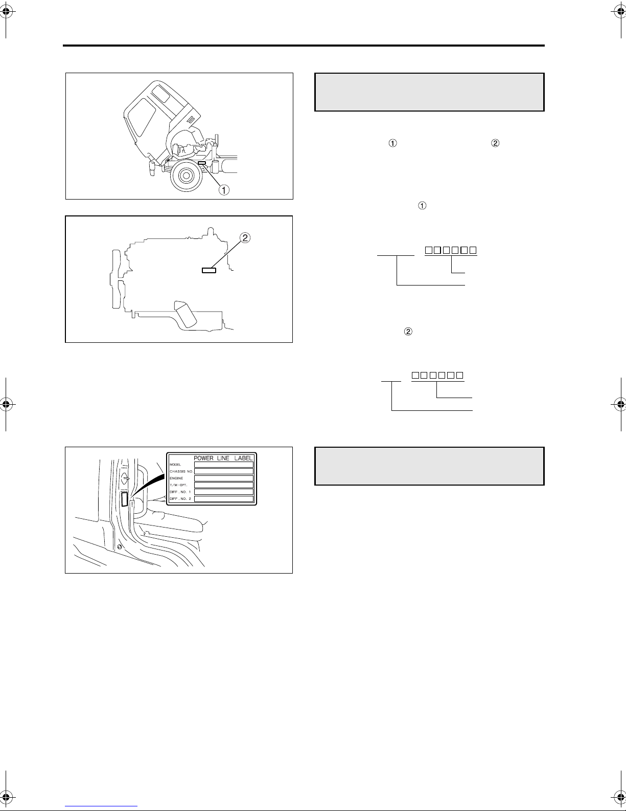
Chassis and engine numbers
If presented at the time of repair or parts order, the
chassis number and engine number will facilitate the quick and smooth processing of your
requests.
Z11685
Z11660
1 Chassis number
The chassis number is indicated on the left
frame, near the left front wheel.
Example: FK61FH -
Chassis number
Vehicle model
2 Engine number
The engine number is indicated on the left side of
the crankcase.
Example: 6M6 -
Engine number
Engine model
Powerline label
The powerline label located in the position shown
indicates the vehicle model, chassis number and
information relevant to the vehicle’s power transmission components.
Z11686
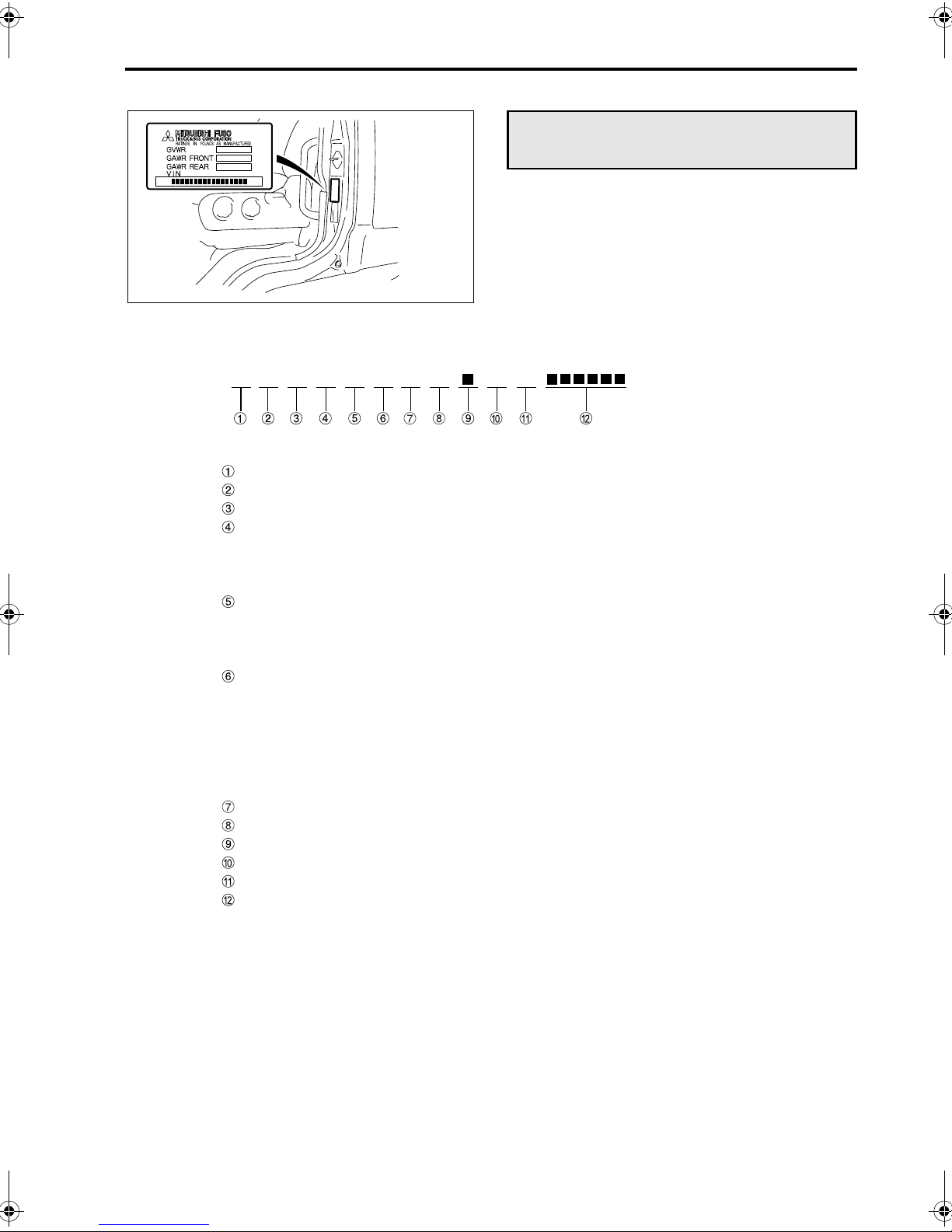
Vehicle identification number (VIN)
The VIN is stamped on a plate that is located as
shown in the illustration.
The VIN comprises 17 numbers and letters, the
meanings of which are listed below.
Z10244
J FD6L H 6E1 K
Country J: Japan
Make L: Mitsubishi Fuso
Type 6: Incomplete vehicle
Gross vehicle weight/Brake system
D: 19‚501 to 26‚000 lbs./Air over hydraulic
F: 26‚001 to 33‚000 lbs./Full air
G: 16,001 to 19,500 lbs./Air over hydraulic
Line F: FK61F
G: FM61F
H: FM64F
J: FM65F
Series (Wheel base) F: 3.5 to 3.79 m (11.48 to 12.43 ft.)
H: 4.1 to 4.39 m (13.45 to 14.40 ft.)
J: 4.4 to 4.69 m (14.43 to 15.38 ft.)
K: 4.7 to 4.99 m (15.41 to 16.37 ft.)
L: 5.0 to 5.29 m (16.40 to 17.35 ft.)
M: 5.3 to 5.59 m (17.38 to 18.33 ft.)
P: 5.9 to 6.19 m (19.35 to 20.30 ft.)
Cab/chassis type 1: Chassis cab
Engine E: 7.545 L diesel turbo charged and charge air cooled
Check digit
Model year 6: 2006
Plant K: Kawasaki
Plant sequential No.
1-3
1-4 Recommendation to drivers
Z00011
Maintenance
Checking your vehicle at regular intervals is very
important for maximizing performance and extending service life. It is recommended that you make a
habit of performing the following inspections.
This manual describes simple maintenance checks
and procedures that can be carried out by the
owner. If you have difficulty or your vehicle needs
maintenance work that is not shown in this manual,
please refer to an authorized dealer.
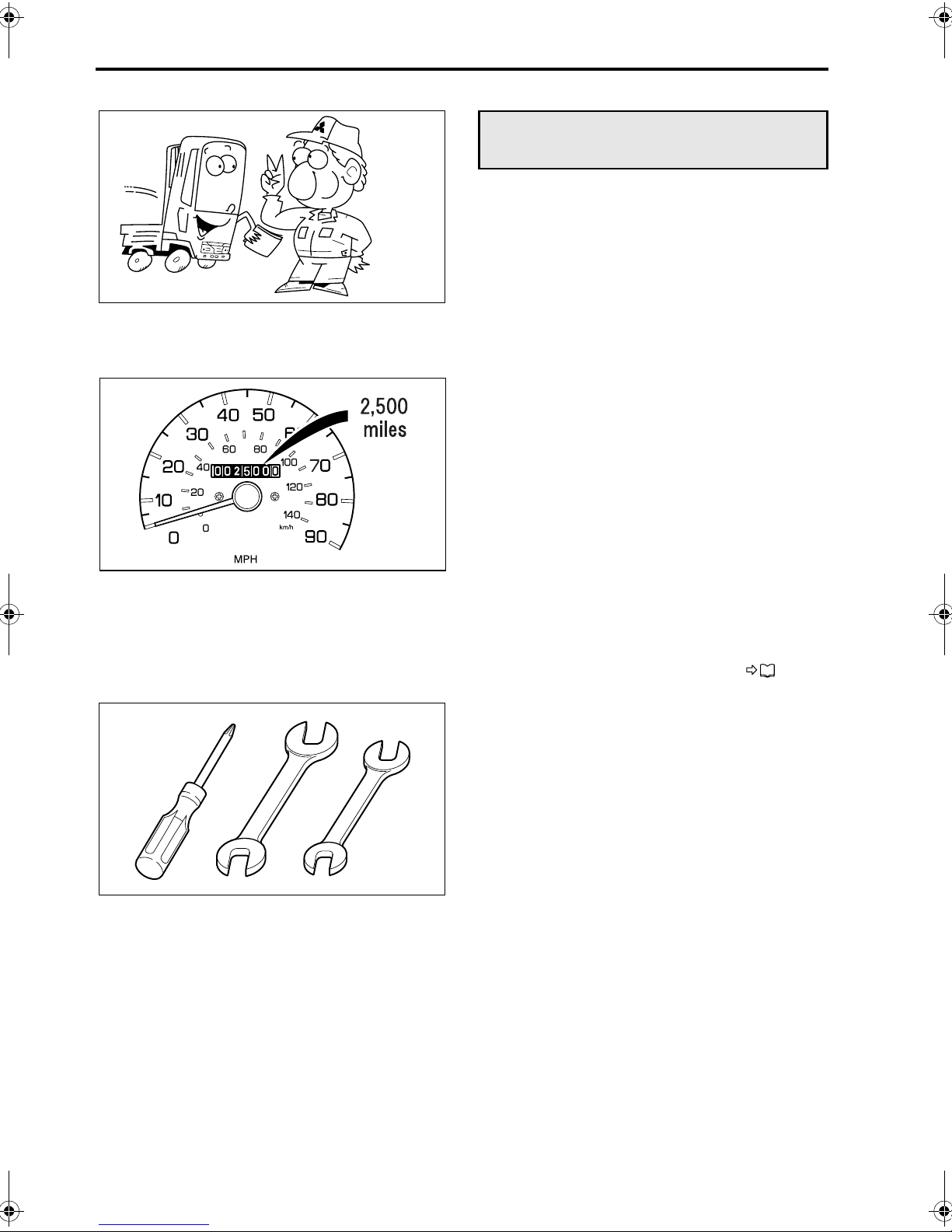
1 New vehicle inspection
After you have driven the first 4‚000 km (2‚500
miles), your vehicle requires a special inspection
and adjustments to compensate for the initial run-in
of various parts. When the distance has been
reached, have your vehicle inspected by an authorized dealer by showing them this Owner’s Manual.
Z13615
Z01367
NOTE:
The cost of oil, Lubricants, parts and any work that
is not included in the new vehicle inspection must
be borne by the owner.
2 Pre-operational check
Make a habit of checking your vehicle at the start of
every day’s operation. This will ensure safe and
comfortable operation. P. 12-8
3 Periodic inspection
In addition to maximizing the vehicle’s working
•
life, regular inspections also help prevent accidents.
Periodic inspection is based on either the distance traveled (odometer reading) or period of
use (months/years).
• The intervals between and content of periodic
inspections are as shown in the Maintenance
Schedule section.
Please adhere to the maintenance schedule
carefully.

Z01368
1-5
Fuels
Use only diesel fuel, without any additives, for diesel engines installed in Mitsubishi Fuso trucks.
1 Diesel-fuel properties
The following recommendations concerning diesel
fuel used with Mitsubishi Fuso diesel engines are
given for optimum fuel economy and performance.
Use condition Recommendation
Normal operation at
temperatures above
–12°C (10°F)
Operation at temperatures below –12°C
(10°F), or long-hour noload operation.
NOTE:
* ASTM is an acronym for the American Society for
Testing and Materials which recommends fuel containing 0.05% or less sulfur content.
Note that a sulfur content exceeding 0.05% deteriorates the performance of emission control device.
To meet fuel requirements exactly, it is necessary to
obtain cooperation from a reputable fuel oil supplier.
Both fuel suppliers and users are responsible for
keeping fuel clean.
ASTM D-975
Grade Low Sulfur
Grade 2-D*
ASTM D-975
Grade Low Sulfur
Grade 1-D*
2 Danger of fire and explosion by using
mixed fuel
Do not use diesel fuel mixed with gasoline, gasohol
and/or alcohol. Fuel containing 5% gasoline has a
flash point as low as 0°C (32°F), which can lead to a
fire or explosion while the engine is running.
DANGER
• NEVER MIX DIESEL FUEL WITH GASO-
LINE, GASOHOL OR ALCOHOL.
USE OF FUEL MIXED WITH ONE OR MORE
OF THESE COULD LEAD TO A FIRE OR
EXPLOSION INVOLVING SERIOUS
INJURY, DEATH OR PROPERTY DAMAGE.
• IF YOU MISTAKENLY FILL THE FUEL
TANK WITH A MIXED FUEL, DRAIN OUT
ALL THE FUEL FROM THE FUEL SYSTEM.
1-6 Recommendation to drivers
3 Adverse effects of mixed fuel on engine
Using diesel fuel mixed with gasoline, alcohol, or
both, has the following adverse effects on the
engine:
• Fuel viscosity becomes lower, resulting in
excessive wear, damage, and failure of fuel system parts.
• Difficulty in starting the engine will result due to
a reduced cetane number.
CAUTION
The lower the cetane number, the more likely
internal engine damage will occur.
4 Refueling
WARNING
• Stop the engine before fueling.
• Never smoke when fueling since diesel
fuel could ignite or explode. Never operate
lighters or other items that emit sparks.
Z11794
CAUTION
When refueling the vehicle, take care to prevent
dirt and water from entering the fuel tank.
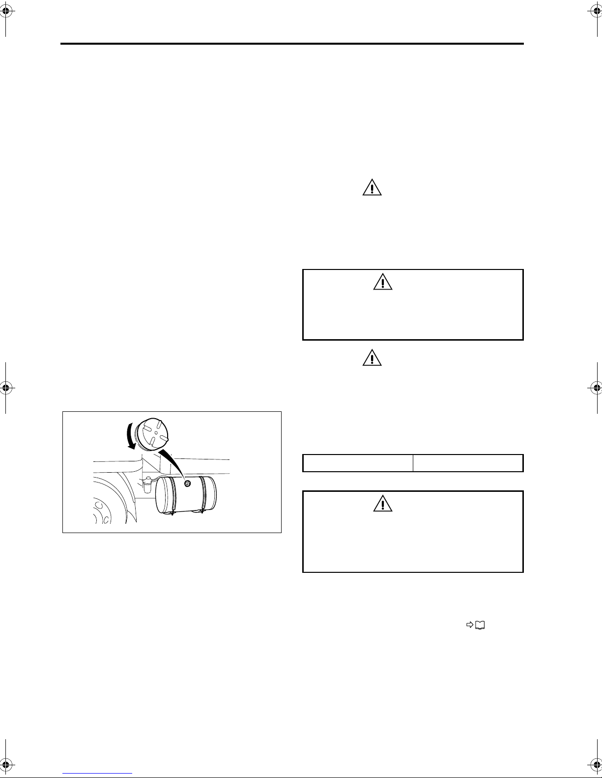
The fuel tank is on the left-hand side of the vehicle.
To open the cap, slowly turn it counterclockwise. To
close the cap, turn it fully clockwise.
Fuel tank capacity 200 liters (52.8 gallons)
WARNING
If you inadvertently put gasoline in the fuel
tank, pump it all out. Running the engine with
gasoline in the tank could cause a fire or
explosion endangering your or other people’s lives.
NOTE:
If you run out of fuel, refuel the tank. After refueling
an empty tank, be sure to air bleed the fuel system.
Otherwise, the engine will not start. P. 13-17
1-7
Handling of the new vehicle
The way the vehicle is handled when new greatly
affects its subsequent performance and service life.
Observe the following precautions when handling
the new vehicle.
Z08648
Z02858
1 Maintenance
The “new vehicle inspection” is very important for
extending the service life of your vehicle. We
strongly recommend that you have this inspection
carried out by an authorized dealer. Be sure to give
the dealer this manual at that time.
During the initial run-in period, oil is quickly contaminated. Replace the following oils at the time of the
“new vehicle inspection”.
At 4‚000 km (2‚500 miles)
• Power steering fluid
• Power steering fluid filter element
• Engine oil
• Manual transmission gear oil
• Axle housing gear oil
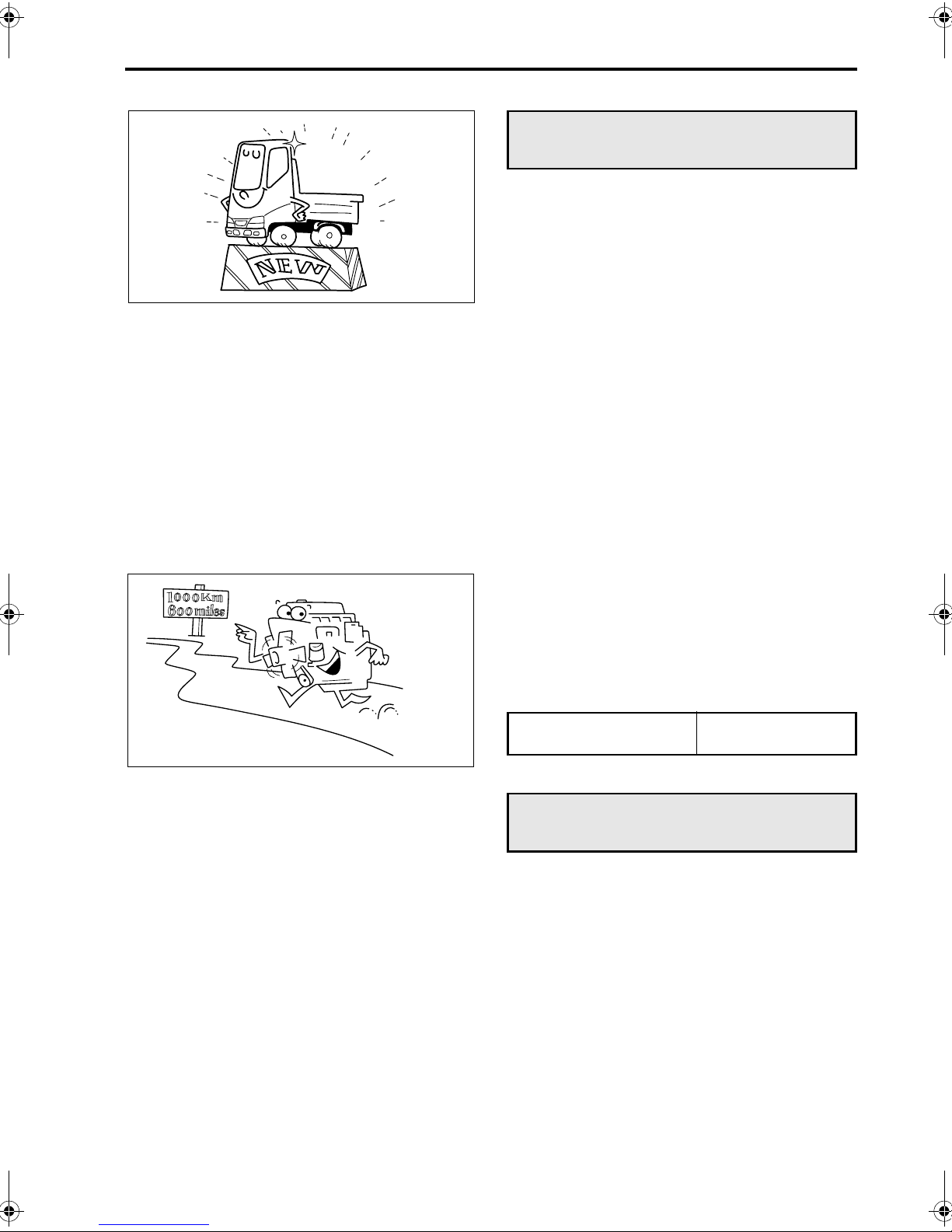
2 Maximum engine speed during run-in
period
To avoid overburdening the new engine, limit
engine RPM to those listed below for the first 1‚000
km (600 miles).
Then, run in your vehicle step by step at various
speeds, beginning with low gears.
Maximum engine speed
during run-in period
2‚000 rpm
Reporting safety defects
If you believe that your vehicle has a defect that
could cause a crash or could cause injury or death,
you should immediately inform both the National
Highway Traffic Safety Administration (NHTSA) and
Mitsubishi Fuso Truck of America, Inc. (MFTA).
If NHTSA receives similar complaints, it may open
an investigation, and if it finds that a safety defect
exists in a group of vehicles, it may order a recall
and remedy campaign. However, NHTSA cannot
become involved in individual problems between
you, your dealer, or MFTA.
To contact NHTSA, you may either call the Auto
Safety Hotline toll-free at 1-800-424-9393 (or 1-202366-0123 in Washington, D.C. area) or write to:
NHTSA, U.S. Department of Transportation, Washington, D.C. 20590.
You can also obtain other information about motor
vehicle safety from the Auto Safety Hotline.

1-8 Recommendation to drivers
Obtaining service
At Mitsubishi Fuso Truck of America, Inc. (MFTA),
we are proud of the quality and workmanship that is
built into every MFTA Truck. We are equally proud
of our corporate commitment to promote the highest
possible degree of customer satisfaction with our
products and services.
Today’s trucks are extremely complex and are comprised of an enormous number of individual parts.
Occasionally, a failure of one of these parts may
occur. Should you experience such a failure, we are
confident that you will find an Authorized Dealer
prepared to provide you with high quality service.
Every Authorized Dealer has trained personnel,
plus the tools and equipment necessary to provide
for your various service needs. In the event that a
problems arises, we ask you to follow the procedure
outlined as follows, and in the sequence listed:
STEP 1: Contact your Nearest Authorized Dealer
This is the most direct and expedient way to obtain
service. Each Authorized Dealer has the ultimate
responsibility for providing the services and repairs
you may need. We recommend that you contact the
Service Manager of your nearest Authorized Dealer
for assistance. In the event that you feel additional
assistance is required, ask to speak to the General
Manager of the Authorized Dealer.
STEP 2: Contact MFTA
After the completion of Step 1, and in the event that
your nearest Authorized Dealer has been unable to
satisfactorily resolve the problem, please contact
MFTA’s Customer Service Representative at 1-877-
711-0707.
Please be prepared to provide the following information when you call:
• Your Name, Company Name, Address, Tele-
phone Number
• Vehicle Model
• Vehicle Model Year
• Vehicle Identification Number
• Mileage
• Name of Dealer contacted under Step 1, if appli-
cable
• Details of the Complaint/Comment
You also may correspond with the Customer Service Representative in writing, addressed to:
MITSUBISHI FUSO TRUCK OF AMERICA, INC.
CUSTOMER SERVICE REPRESENTATIVE
2015 CENTER SQUARE RD.
LOGAN TOWNSHIP, NJ 08085

2-1
2. Warning labels
Locations in cab . . . . . . . . . . . . . . . . . . . . . . . . . . . . . . . . . . . . . . . . . . . . . . . . . . . . . . . . . . . . . . . . . . . . . 2-2
Locations outside cab . . . . . . . . . . . . . . . . . . . . . . . . . . . . . . . . . . . . . . . . . . . . . . . . . . . . . . . . . . . . . . . . 2-4
2-2 Warning labels
• The caution and warning labels show important
information. Be sure to read them before using
the vehicle.
• If any label has peeled so it is difficult to read, is
scratched or otherwise damaged, or has peeled
off completely, please inform an authorized
dealer. The warning and caution labels apply
only to the vehicle itself, not to any equipment
mounted on the vehicle. For information on caution and warning labels that apply to equipment
mounted on the vehicle, please refer to the
Owner’s Manual supplied by the manufacturer
of the equipment.
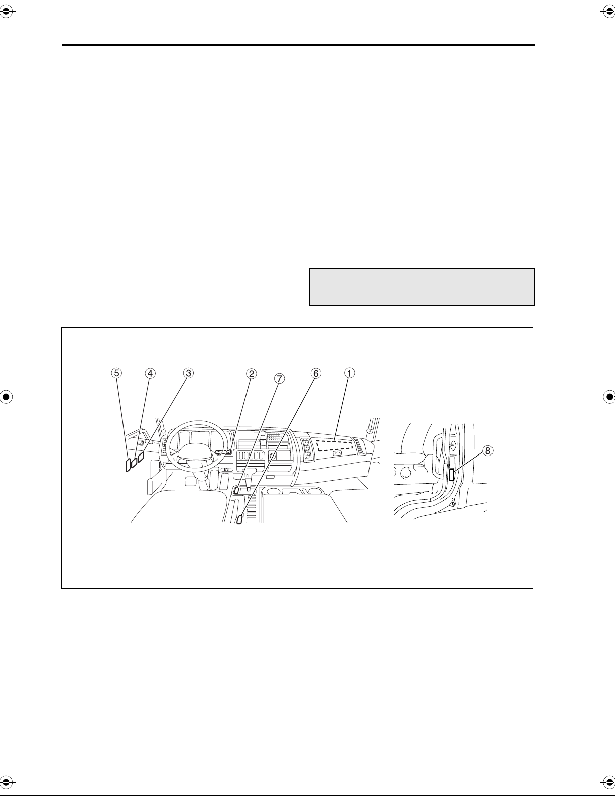
• The caution and warning labels are located in
the cab as shown below. Samples of these
labels are indicated in this and following pages.
Locations in cab
Z11661
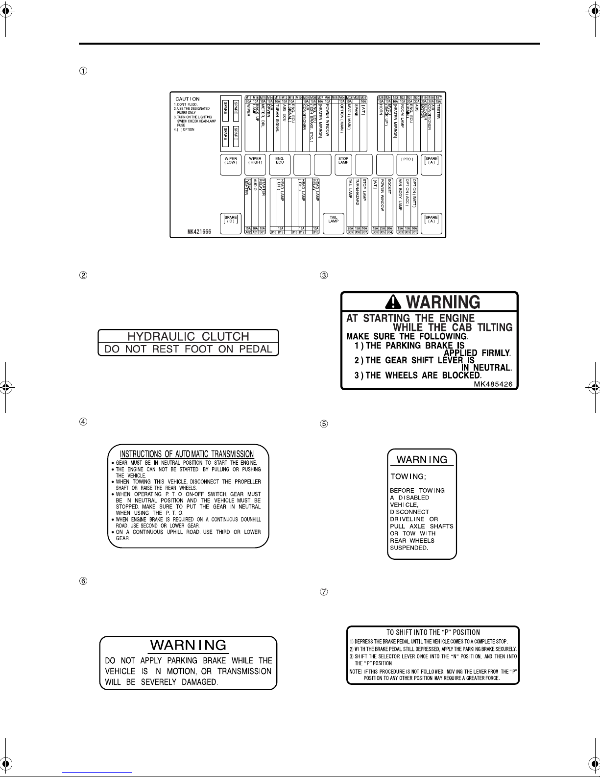
Fuse
2-3
Z11662
Clutch pedal <Manual transmission vehicles>
Z11663
Automatic transmission
<Automatic transmission vehicles>
Z11665
Starting the engine while the cab is tilting
Z11664
Towing
<Automatic transmission vehicles>
Z11666
Parking brake
<Automatic transmission vehicles>
Z11667
To shift into the “P” position
Z12206
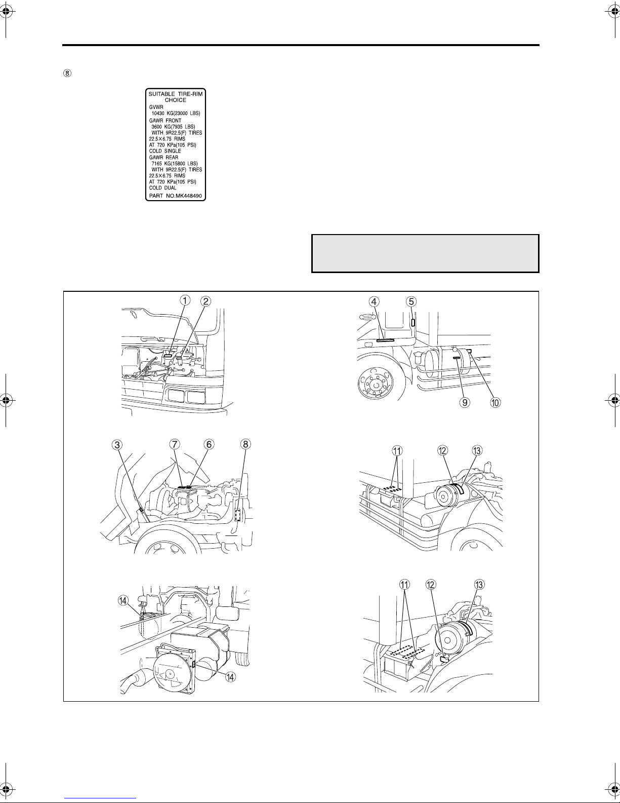
2-4 Warning labels
Tire and rim
Z11668
Locations outside cab
<FM65F automatic transmission vehicles>
Z11669
Z11670
Z12299
Z11730
<FK>
Z11671
<FM>
Z11731
2-5
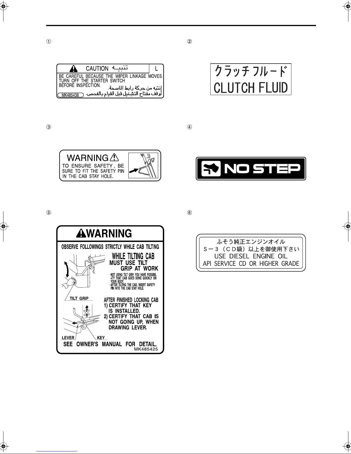
Wiper linkage
Tilting the cab
Z11672
Z11673
Clutch fluid <Manual transmission vehicles>
Z11683
No step <FM>
Z11674
Tilting the cab
Engine oil
Z10084
Z11675
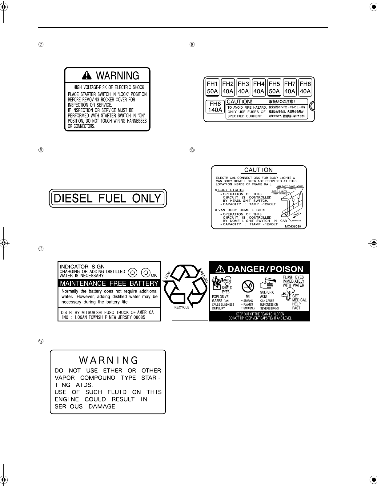
2-6 Warning labels
High voltage
Fuel
Z11676
High current fuses
(This applies to the vehicles other than FM65F
automatic transmission vehicles)
Z11677
Connectors for body lights and van body dome
lights
Battery
Starting the engine
Z11678
Z11679
Z11680
Z11681
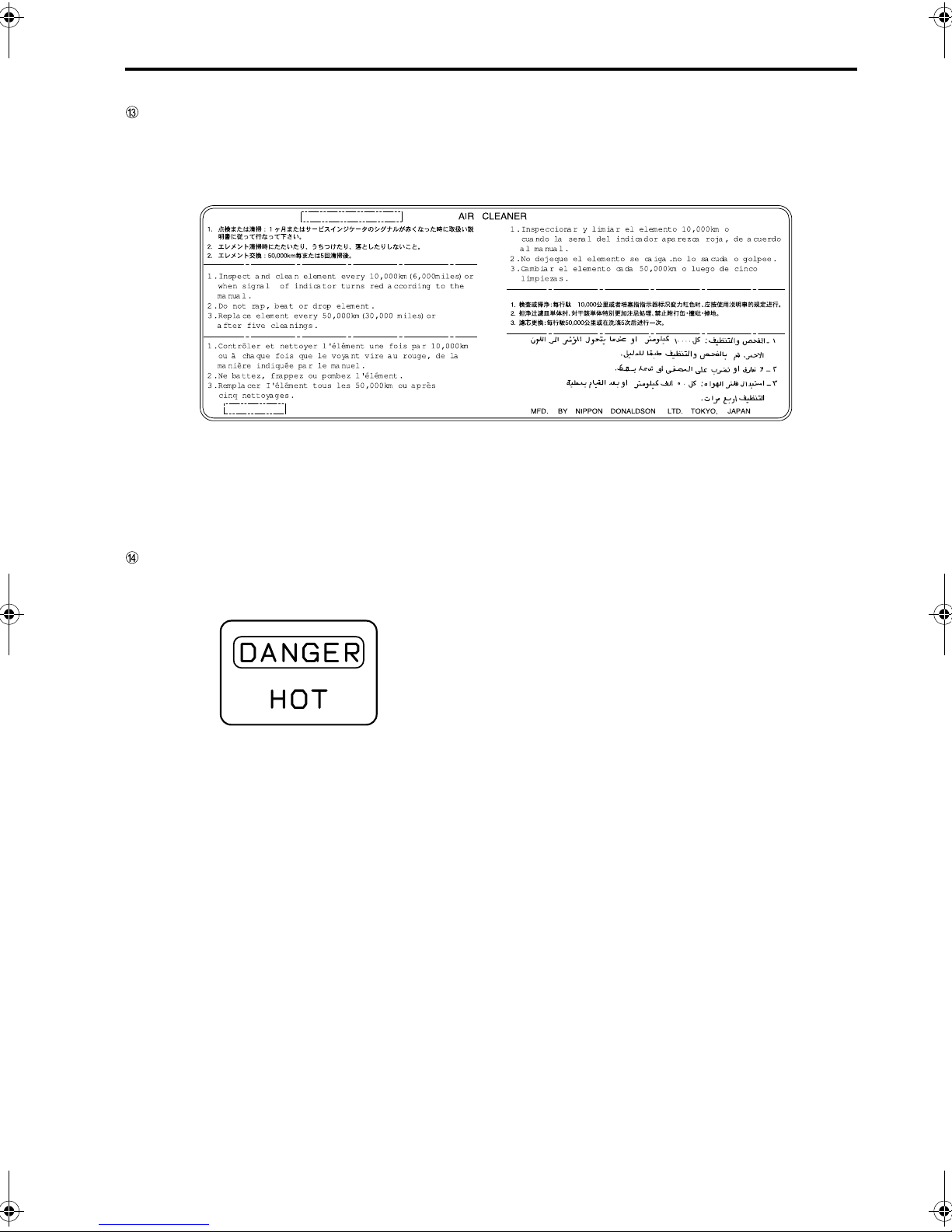
Air cleaner
2-7
Automatic transmission oil cooler
<FM65F automatic transmission vehicles>
Z09802
Z12300


3-1
3. Opening and closing
Starter key . . . . . . . . . . . . . . . . . . . . . . . . . . . . . . . . . . . . . . . . . . . . . . . . . . . . . . . . . . . . . . . . . . . . . . . . . 3-2
Doors . . . . . . . . . . . . . . . . . . . . . . . . . . . . . . . . . . . . . . . . . . . . . . . . . . . . . . . . . . . . . . . . . . . . . . . . . . . . . 3-2
Central door locks . . . . . . . . . . . . . . . . . . . . . . . . . . . . . . . . . . . . . . . . . . . . . . . . . . . . . . . . . . . . . . . . . . . 3-4
Entering and leaving the vehicle . . . . . . . . . . . . . . . . . . . . . . . . . . . . . . . . . . . . . . . . . . . . . . . . . . . . . . . . 3-4
Door window glass . . . . . . . . . . . . . . . . . . . . . . . . . . . . . . . . . . . . . . . . . . . . . . . . . . . . . . . . . . . . . . . . . . . 3-5
Rear quarter window . . . . . . . . . . . . . . . . . . . . . . . . . . . . . . . . . . . . . . . . . . . . . . . . . . . . . . . . . . . . . . . . . 3-6
3-2 Opening and closing
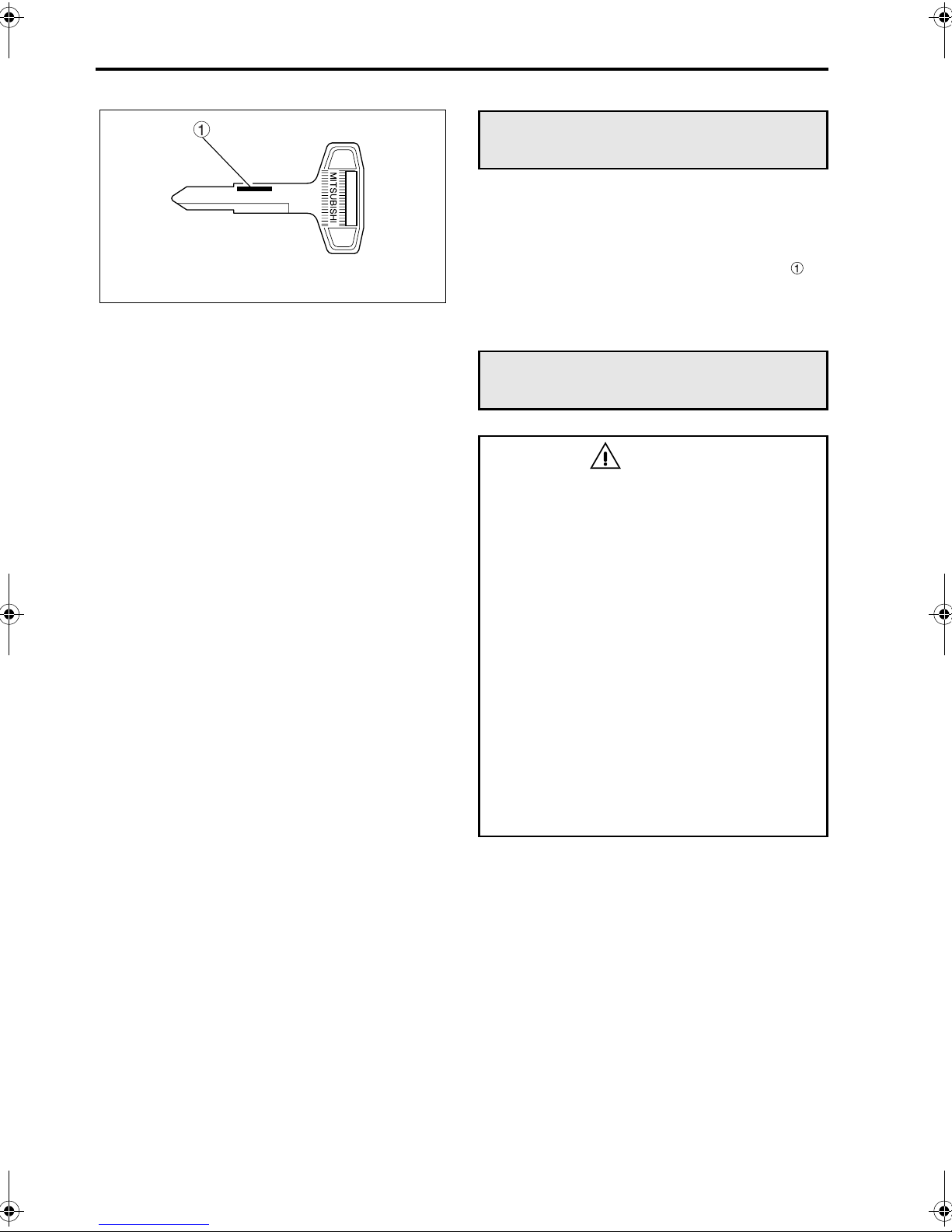
Z11687
Starter key
• Your vehicle is provided with two identical starter
keys.
• The starter key can be used to start and stop the
engine and lock and unlock the doors.
• Make a note of your starter key number so
that you can order a replacement key from an
authorized dealer in the event that it is lost.
Doors
WARNING
• To help prevent accidents, always check
for vehicles and pedestrians approaching
from behind before opening the doors.
• Driving with a door ajar can be very dan-
gerous. Make sure the doors are completely closed before starting.
• Exercise caution when opening a door in
strong wind. Otherwise, the wind could
catch the door and suddenly blow it open.
• Exercise caution when opening a door on
a downward slope. Otherwise, the inclination of the vehicle could cause the door to
suddenly fall open.
• When leaving the vehicle, take with you
any child who was riding in the cab. Never
leave a child in the cab. A child left in the
cab could interfere with the vehicle, causing it to move or catch fire. Also, the cab
gets extremely hot in sunshine and in hot
weather so a child left in the cab could suffer heatstroke.
Z11688
Z11704
Z11689
3-3
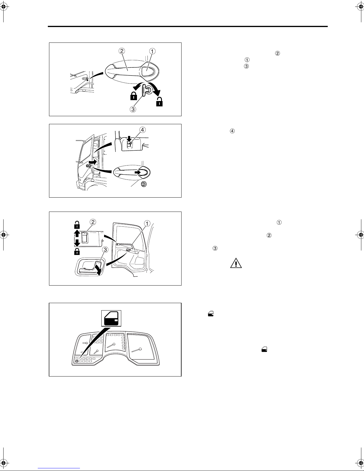
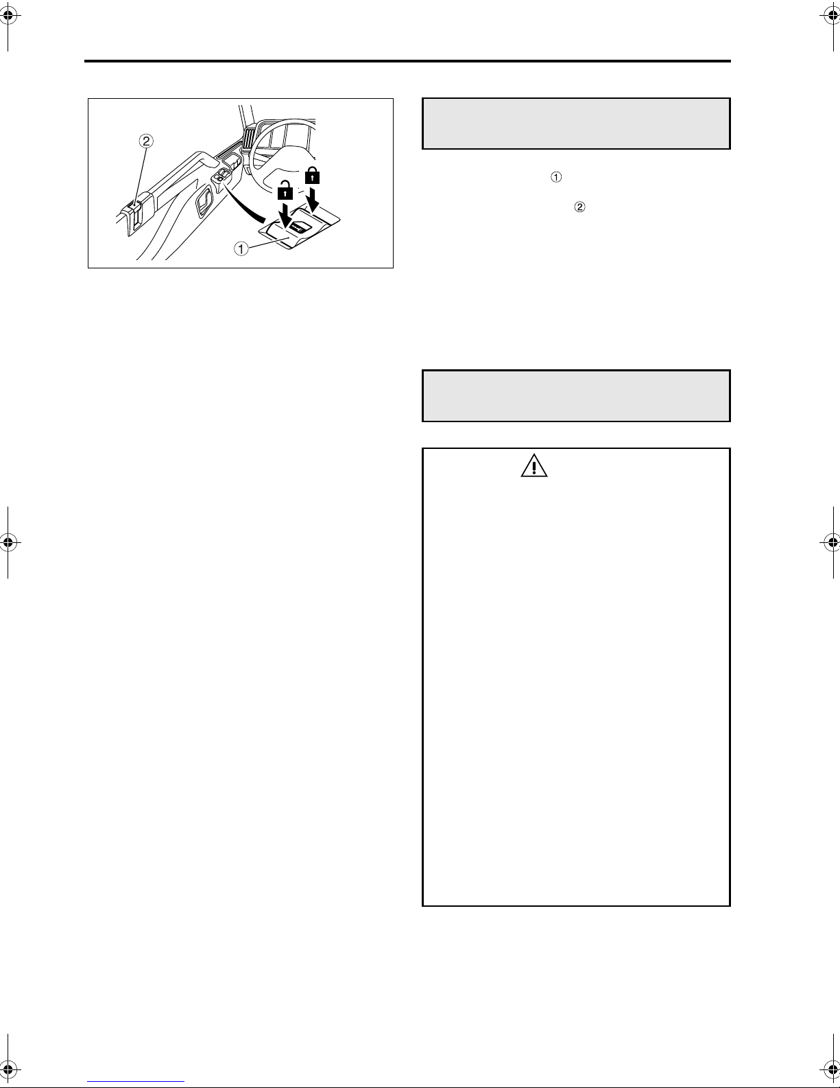
1 From the outside
To open, pull outer handle toward you while
•
pressing button .
• Use starter key to lock or unlock the door.
• To lock the door without using starter key, press
lock knob to the lock position and then, while
pressing the button, close the door.
NOTE:
• When you lock the driver’s door using the starter
key or by lowering the lock knob, the passenger’s door is automatically also locked.
• When you leave your vehicle, be sure to remove
the starter key from the starter switch and lock
all doors to prevent theft.
• Be careful not to lock the doors with the starter
key inside the vehicle.
Z11704
Z11705
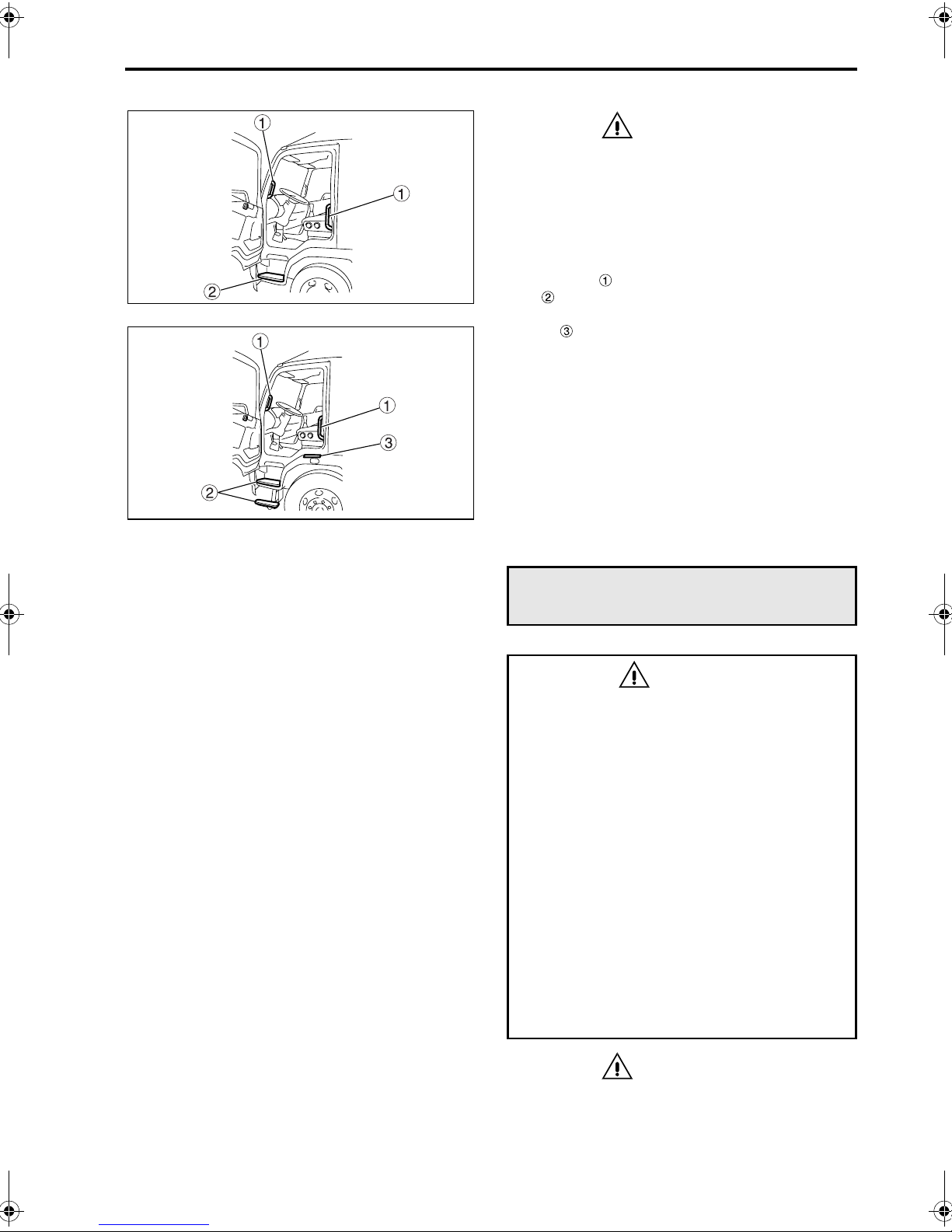
2 From the inside
To close, pull door waist bar .
•
Be sure to close the door completely.
• To lock, press lock knob .
• To open, raise the lock knob and pull inner han-
dle .
CAUTION
Closing the door by pulling any part other than
the waist bar could damage the door mechanism.
3 When the door is open
The indicator lamp illuminates when the door is
opened or not closed completely with the starter key
in the ON position. If the door does not close completely, close it again properly.
NOTE:
If the interior lamp button is pressed, the interior
lamp illuminates whenever the door is opened.
3-4 Opening and closing
Z05906
Central door locks
• When the switch is pressed, both doors are
locked or unlocked simultaneously.
• When the lock knob on the driver’s door is
lowered, the passenger’s door is also automatically locked. If the lock knob on either door is
subsequently lifted, only that door is unlocked.
• When the driver’s door is locked from the out-
side using the starter key, the passenger’s door
is automatically also locked. If the starter key is
subsequently used to unlock either door, the
other door remains locked.
Entering and leaving the vehicle
WARNING
• Always use the step to climb into or down
from the vehicle. Never put your foot on
the wheel or tire since it could easily slip
off.
• The step can become slippery in rain or
snow. Firmly hold the grip while climbing
into or down from the vehicle. Holding the
grip is particularly important when snow
has settled and frozen on the step.
• If the soles of your shoes are oily or
greasy, you could slip when climbing
down from the vehicle or when operating
the brake or clutch pedal. Wipe any oil and
grease off the soles of your shoes before
entering or leaving the vehicle.
• When putting your foot on the step, make
sure your body is supported in three
places for safety.
• Do not hold luggage or other items in your
hands when entering or leaving the vehicle since this can be dangerous.
• Do not jump down from the vehicle. Jump-
ing down from the vehicle could cause you
to fall or sustain an injury.
• Take care when entering or leaving the
vehicle on a slope or in a strong wind
since the door could open or close suddenly.
3-5
<FK>
<FM>
Z11732
Z11733
CAUTION
• Hold onto the grip when entering or leaving
the vehicle. Do not grasp any other part of the
vehicle since it could break.
• Do not step on a fender. Doing so not only
may damage the fender but also can be dangerous as it is slippery.
Hold the grip tightly and put your foot fully on the
step when entering or leaving the vehicle. If you
place your hand on the fender, put it on the non-slip
section .
Door window glass
WARNING
• Do not put your hands or head outside a
window or let anyone in your vehicle do
so. Serious injury could result from external objects or in the event of sudden braking. Be particularly careful when carrying a
child in your vehicle.
• Always make sure that no one has their
head or hands out of the window when
closing it.
A body part could be injured if caught in a
closing window.
Never allow a child to open or close the
window.
• When a child is in the cab, be sure to press
the power window lock switch to prevent
the child from opening and closing the
assistant driver’s window. Otherwise, the
child may accidentally operate the power
window switch and get its hands or head
trapped.
CAUTION
Do not keep any door or window open in rainy
weather, and be careful not to spill a drink on
any of the window switches. If water or any
other liquid gets on a window switch, it can
cause a malfunction.
3-6 Opening and closing
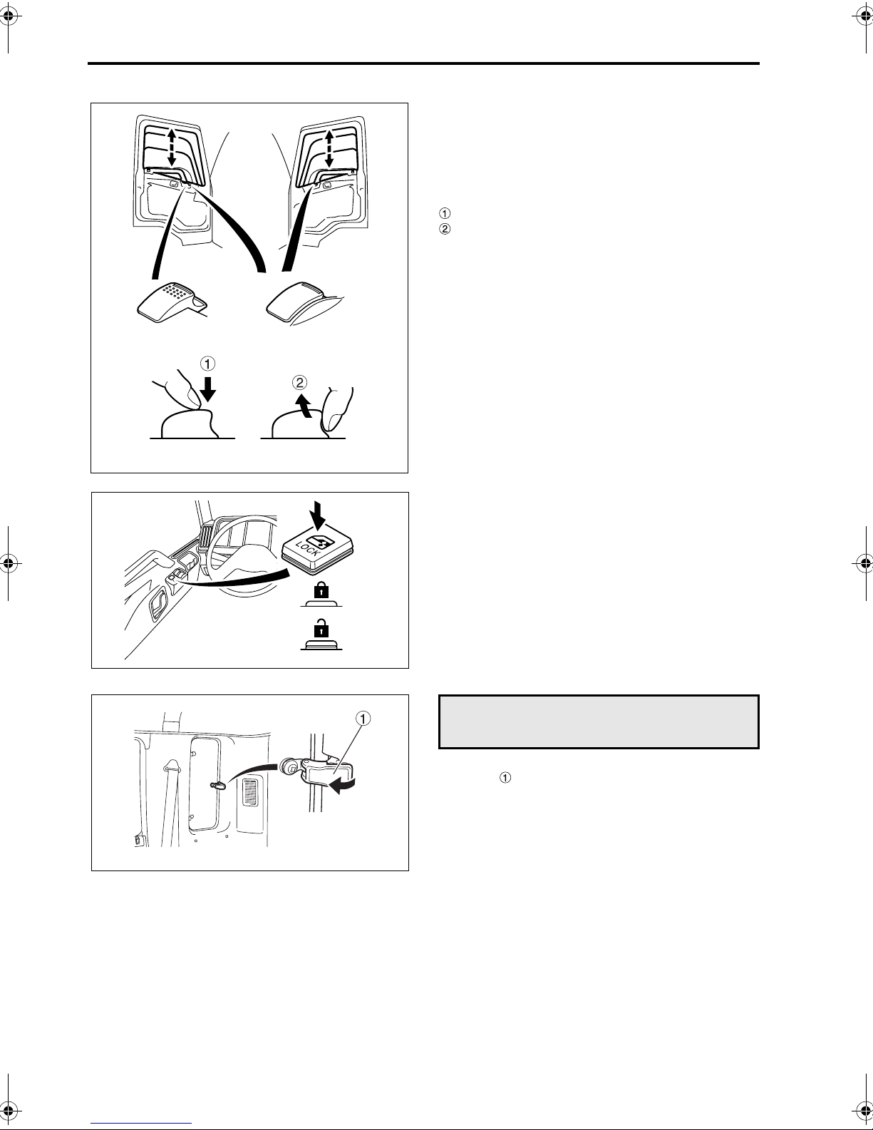
1 Power window switches
The power window switches function only when the
starter switch is in the “ON” position.
On the driver’s door, there are two switches: one for
controlling the driver’s window and the other for
controlling the passenger’s window.
Press the switch to open the window.
Raise the switch to close the window.
Z05907
Z05908
Z11708
2 Power window lock switch
Press the power window lock switch to prevent the
passenger’s window from being opened or closed.
Pressing the switch a second time releases the
lock.
NOTE:
If a child is in your vehicle, it is important for safety’s
sake to press the power window lock switch to prevent the child from opening or closing the passenger’s window.
Rear quarter window
Pull latch , and push it outward to open.

4-1
4. Seat and steering wheel adjustments
Seats . . . . . . . . . . . . . . . . . . . . . . . . . . . . . . . . . . . . . . . . . . . . . . . . . . . . . . . . . . . . . . . . . . . . . . . . . . . . . 4-2
Seat belts . . . . . . . . . . . . . . . . . . . . . . . . . . . . . . . . . . . . . . . . . . . . . . . . . . . . . . . . . . . . . . . . . . . . . . . . . . 4-5
Steering wheel . . . . . . . . . . . . . . . . . . . . . . . . . . . . . . . . . . . . . . . . . . . . . . . . . . . . . . . . . . . . . . . . . . . . . . 4-9

4-2 Seat and steering wheel adjustments
Seats
WARNING
• Avoid adjusting the seat while the vehicle
is moving since the seat may move more
than you intend and cause an accident by
impeding operation of the vehicle. Be sure
to stop the vehicle and set the parking
brake before performing any adjustment of
the seat.
• After you have adjusted the seat, gently
move or rock the seat to ensure that it is
locked in the desired position.
• When adjusting the seat, keep your hands
away from the bottom of the seat and from
moving parts of the seat. Otherwise, you
could suffer an injury by getting your
hands and fingers trapped.
Z11715
1 Correct driving position
•
Before driving the vehicle, adjust the driver’s
seat with reference to the following points:
Your back must touch the seatback, and you
must be able to see the warning lamps and
gauges.
You must be able to reach and firmly press
the pedals.
You must be able to operate the steering
wheel and switches with ease.
You must be able to operate the gearshift
lever or range selector lever with ease.
You must be able to fasten the seat belt correctly. P. 4-5
• Adjust the steering wheel to a position at which
you can operate it comfortably with your arms
slightly bent. P. 4-9
2 Driver’s seat
Slide lever
Reclining lever
Front height adjustment knob
Rear height adjustment knob
Head restraint
Lumbar support knob
Z11716

Z11717
4-3
2.1 Front/rear slide adjustment
With the slide lever pulled, slide the seat forward or
backward to the desired position.
2.2 Recline adjustment
WARNING
When adjusting the recline angle, sit back
against the seatback or place your hand on it.
Unless restrained, the seatback could return
forward suddenly and injure your face or
other body parts.
Z11718
Z11719
Pull the reclining lever and set the seatback at the
desired angle.
2.3 Seat height adjustment
Adjust the height and angle of the seat cushion by
turning the front height adjustment knob and rear
height adjustment knob .
2.4 Head restraint
WARNING
Before driving, adjust the head restraint to
the correct position and make sure it is
locked.
• Up/down adjustment
Make up/down adjustments so that the middle of
the head restraint is behind your head.
To raise or lower the head restraint: Slide it while
pressing the head restraint knob .
Z11720
• Removing and refitting the head restraint
To remove the head restraint: Press the head
restraint knob and pull the head restraint off the
seat.
To refit the head restraint: Slide it into the seat,
press the head restraint knob, and lower the head
restraint in position.

4-4 Seat and steering wheel adjustments
30 mm
2.5 Lumbar support
Turn the lumbar support knob to adjust the firmness
with which the seatback supports your lower back.
Z11721
2.6 Air suspension seat
<Standard on FM65F>
• Adjusting the seat suspension air pressure to
your body weight is important to ensure the best
seating comfort.
Adjust the air pressure as follows:
1. Rotate the front and rear height adjusting
knobs to bring the seat into its lowest position.
2. Place yourself in the seat and move air pressure adjusting lever until the seat top surface is approx. 30 mm below the edge of
seat belt buckle .
3. Now the air pressure has been adjusted to
your body weight.
Adjust the seat height as desired by using
the front and rear height adjusting knobs.
Z03527
Z11722
CAUTION
Without a proper air pressure adjustment, you
may experience uncomfortable riding under certain road conditions.
• The following two seat suspension settings can
be selected using adjustment lever according
to the road conditions:
SOFT:
For a soft ride on normal roads.
HARD:
For minimizing bumpy ride on rough roads.
3 Passenger’s seat
WARNING
During vehicle operation, the seatback must
not be reclined further than necessary. In the
event of sudden braking, the occupant could
slide forward and suffer severe injuries.

Z11723
4-5
Reclining lever
Head restraint
For front/rear adjustments of the seat, up/down
adjustments of the head restraint, and removal and
installation of the head restraint, follow the same
procedures as for the driver’s seat.
4 Center seat
The seatback can be folded down by moving lever
. Secure the folded seatback with strap .
Z11724
Z11725
Seat belts
• To help prevent injury in the event of a sudden
stop or accident, the driver and all passengers
must wear their seat belts correctly.
• When wearing your seat belt, sit back in your
seat with your back straight. If a seat belt is used
incorrectly, its effectiveness is greatly diminished and it could aggravate injuries in the event
of accident.
• For details of seat belt usage for children and
pregnant women, refer to page 4-8.

4-6 Seat and steering wheel adjustments
WARNING
• Passenger’s must never be in the cargo
area while the vehicle is in motion. Unless
seated and properly belted up, the risk of
injury is greatly increased.
• Seat belts should be worn as low as possi-
ble over the hips. Wearing a seat belt
across the abdomen could be dangerous
since undue pressure would be placed on
internal organs in the event of a collision.
• Make sure that the seat belt is not twisted
when fastening it. A twisted seat belt could
be dangerous since its reduced width will
apply a larger force to a smaller part of
your body in the event of impact.
• Replace any seat belt that is cut or frayed,
or if its buckle does not work properly.
• Never use a single seat belt for more than
one person.
• It is dangerous to fasten or unfasten your
seat belt while driving since the momentary diversion of your attention could lead
to a serious accident. Always stop the
vehicle first.
Z10760
• The seats feature 3-point lap and shoulder belts
with Emergency Locking Retractor (ELR).
1 Three-point ELR seat belt
NOTE:
It is not necessary to adjust the length of these seat
belts.
An ELR seat belt extends and retracts automatically
as its wearer moves but locks automatically for protection in the event of a sudden stop or shock.
The belt’s tightness should be adjusted automatically. If there is any looseness, lift the shoulder belt
gently and the mechanism will take up the slack.
With the belt properly tightened, the risk of it slipping off in a collision is reduced.
• Fastening
WARNING
The shoulder belt can be dangerous if worn
across the neck. Adjust its position so that it
does not cross over the neck.
1. Hold tang and gently extend the belt. If the
belt locks or is difficult to extend, let it retract and
pull it gently again.
2. Take care that the belt does not become twisted.
Insert the tang into the buckle until you hear a
click.
3. Pull on the tang to confirm that it is locked in.

Z11726
4-7
4. Adjust the belt so it is across your hips and
shoulder.
• Unfastening
1. Press the red button to unlock the buckle.
2. The belt automatically retracts when unlocked.
To prevent the tang causing damage or injury,
hold it while the belt retracts.
3. Adjust the tang stopper to locate the tang in
an easy-to-reach position and prevent it from
slipping.
Z01351
Z08774
2 2-point seat belt
WARNING
For maximum protection in the event of an
accident, the belt must not be loose. A loose
belt could even aggravate injuries.
Fastening
•
1. Take care that the belt does not become twisted.
Inset the tongue into the buckle until you
hear a click.
2. Pull on the tongue to confirm that it is locked in.
3. Adjust the belt so it is low across you hips.
4. To adjust the belt’s length, hold the tongue at
90° to the belt.
Pull the belt end to shorten the belt or the
tongue to lengthen it.
• Unfastening
Press the red button on the buckle to separate
the tongue and buckle.
• Insert tongue into buckle until you hear a
click.
• Press red button to unlock the belt buckle.
• To adjust the seat belt length, hold the tongue at
right angles to the belt. Pull the belt end to
shorten or the tongue to lengthen the belt as
desired.

4-8 Seat and steering wheel adjustments
3 Children and babies
When carrying children or babies, they must be
•
restrained properly to minimize the risk of injury
in the event of a sudden stop or accident. Never
allow children to stand or kneel on the seats. For
maximum safety, we recommend fitting and
using a restraint system that complies with Federal Motor Vehicle Safety Standards. The use of
child and/or baby restraint systems is mandatory
in some states. Please abide by your state’s
regulations.
• Older children may sit on the regular seats and
use the regular seat belts. However, make sure
that the shoulder belts do not cross their necks
or faces.
4 Pregnant women
Since a seat belt could exert undue pressure on the
abdomen in the event of an accident, pregnant
women should consult a doctor about the use of
seat belts before riding in the vehicle. A pregnant
woman should wear her seat belt as low as possible
across the hips, not across her abdomen.
5Seat belt care
•
Periodically, check the action of the mechanical
parts such as the buckles, tangs, and ELR units.
Check also for any damage that could stop the
seat belts from functioning properly.
Replace seat belt unit if there is any malfunction
or damage.
• Replace any webbing that is cut, rayed, or other-
wise damaged.
• Replace any seat belt that has received a shock
due to a collision.
• Keep sharp or other potentially damaging
objects away from the seat belts, especially the
webbing.
• Keep the seat belts clean and dry. Use a mild
soap and lukewarm water to clean seat belts.
Such solvents as gasoline and thinner may seriously affect the strength of webbing.
• Never attempt to bleach or dye the seat belts, as
this could weaken them considerably.
• Do not attempt to remove the seat belts or dis-
assemble the ELR units.

4-9
Steering wheel
The steering wheel can be adjusted to the preferred
height and tilted forward/backward. Adjust the
steering wheel as well as the seat to the best positions for easy, safe driving.
WARNING
• After every adjustment, try to move the
steering wheel back and forth to make
sure that it is securely locked.
Unless the lever returns to the locking
position, the steering wheel may move
while the vehicle is in motion and cause an
accident.
• Adjusting the steering wheel while driving
is dangerous since it could detract from
your concentration or cause the steering
wheel to move more than desired.
Z11727
1. Raise lock lever to adjustment position ,
and adjust the steering wheel to the desired
height and angle.
2. After performing the adjustments, firmly push
the lock lever down to lock the steering wheel
in position.


5-1
5. Switches and controls
Arrangement of switches and controls . . . . . . . . . . . . . . . . . . . . . . . . . . . . . . . . . . . . . . . . . . . . . . . . . . . . 5-2
Starter switch . . . . . . . . . . . . . . . . . . . . . . . . . . . . . . . . . . . . . . . . . . . . . . . . . . . . . . . . . . . . . . . . . . . . . . . 5-3
Cold start switch . . . . . . . . . . . . . . . . . . . . . . . . . . . . . . . . . . . . . . . . . . . . . . . . . . . . . . . . . . . . . . . . . . . . . 5-4
Engine idling control volume . . . . . . . . . . . . . . . . . . . . . . . . . . . . . . . . . . . . . . . . . . . . . . . . . . . . . . . . . . . 5-5
Starting the engine . . . . . . . . . . . . . . . . . . . . . . . . . . . . . . . . . . . . . . . . . . . . . . . . . . . . . . . . . . . . . . . . . . . 5-6
Warming up the engine . . . . . . . . . . . . . . . . . . . . . . . . . . . . . . . . . . . . . . . . . . . . . . . . . . . . . . . . . . . . . . 5-10
Stopping the engine . . . . . . . . . . . . . . . . . . . . . . . . . . . . . . . . . . . . . . . . . . . . . . . . . . . . . . . . . . . . . . . . . 5-12
Pedals . . . . . . . . . . . . . . . . . . . . . . . . . . . . . . . . . . . . . . . . . . . . . . . . . . . . . . . . . . . . . . . . . . . . . . . . . . . 5-13
Gearshift lever . . . . . . . . . . . . . . . . . . . . . . . . . . . . . . . . . . . . . . . . . . . . . . . . . . . . . . . . . . . . . . . . . . . . . 5-14
9-speed transmission . . . . . . . . . . . . . . . . . . . . . . . . . . . . . . . . . . . . . . . . . . . . . . . . . . . . . . . . . . . . . . . . 5-15
Allison automatic transmission LCT 1000/2400 series . . . . . . . . . . . . . . . . . . . . . . . . . . . . . . . . . . . . . . 5-17
Allison automatic transmission MD3060P series . . . . . . . . . . . . . . . . . . . . . . . . . . . . . . . . . . . . . . . . . . . 5-20
Parking brake . . . . . . . . . . . . . . . . . . . . . . . . . . . . . . . . . . . . . . . . . . . . . . . . . . . . . . . . . . . . . . . . . . . . . . 5-22
Combination switch . . . . . . . . . . . . . . . . . . . . . . . . . . . . . . . . . . . . . . . . . . . . . . . . . . . . . . . . . . . . . . . . . 5-24
Van body dome light switch . . . . . . . . . . . . . . . . . . . . . . . . . . . . . . . . . . . . . . . . . . . . . . . . . . . . . . . . . . . 5-28
Brightness control switch . . . . . . . . . . . . . . . . . . . . . . . . . . . . . . . . . . . . . . . . . . . . . . . . . . . . . . . . . . . . . 5-28
Power take-off switch . . . . . . . . . . . . . . . . . . . . . . . . . . . . . . . . . . . . . . . . . . . . . . . . . . . . . . . . . . . . . . . 5-28
Cruise control . . . . . . . . . . . . . . . . . . . . . . . . . . . . . . . . . . . . . . . . . . . . . . . . . . . . . . . . . . . . . . . . . . . . . . 5-29
Air suspension height control . . . . . . . . . . . . . . . . . . . . . . . . . . . . . . . . . . . . . . . . . . . . . . . . . . . . . . . . . . 5-33
5-2 Switches and controls
<Manual transmission vehicles>
<Automatic transmission vehicles>
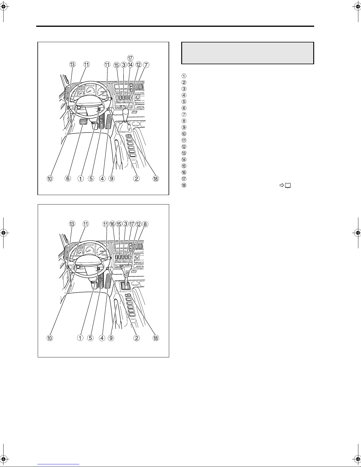
Arrangement of switches and
controls
Starter switch
Engine idling control volume
Cold start switch
Accelerator pedal
Brake pedal
Clutch pedal
Gearshift lever
Range selector lever
Parking brake lever <other than FM65F>
Parking brake control valve <FM65F>
Combination switch
Van body dome light switch
Brightness control switch
Power take-off switch <option>
Cruise control main switch
Power mode switch <other than FM65F>
Height control switch <Air suspension vehicle>
Oil level check switch P. 12-20
Z02466
Z02467
5-3
Starter switch
WARNING
Never turn the starter switch to any position
other than the “ON” position while driving
the vehicle. Turning the starter switch to the
“ACC” position would be dangerous because
the engine would stop and the following
problems would occur:
• The compressed air used to enhance brak-
ing ceases to be generated. This could significantly reduce the effectiveness of the
brakes.
• The power steering system becomes inop-
erative, rendering steering dangerously
sluggish.
• The electrical circuits of the warning
lamps, meters, etc. become inoperative,
causing electric components to malfunc-
tion.
Removing the starter key causes the steering
wheel to lock, making it impossible to steer
the vehicle.
CAUTION
• If you attempt to turn the starter key from the
“ACC” to “LOCK” position without pressing
the reset button, the key will turn only to the
position midway between the “ACC” and
“LOCK” positions (marked “•”). Do not force
the key.
When the reset button is pressed while in
this position, the starter key can be turned to
the “LOCK” position and then removed from
the switch. Once the reset button is pressed,
you need not keep it pressed to be able to
turn the key.
• Do not turn the key to the “S” position while
the engine is running since this could damage the starter.
• If is not possible to move the vehicle with
only the starter. If the engine stops while the
vehicle is on the road, turning the starter
switch to the “S” position will have no effect.
• If you park the vehicle over an extended
period of time, always place the starter key
in the “LOCK” position and remove it from
the starter switch, or keep it in the position
midway between the “ACC” and “LOCK”
positions (marked “•”). Leaving the key in
the “ON” or “ACC” position could run down
the battery.
5-4 Switches and controls
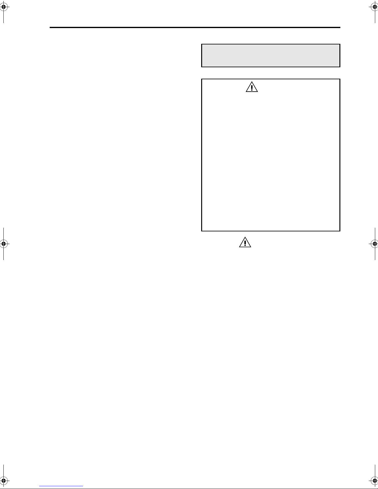
Z11728
Z00046
• LOCK:
Starter key can be inserted and removed only
when it is in this position. To return the starter
key to the “LOCK” position, first turn the key to
the position midway between the “ACC” and
“LOCK” positions (marked “•”), and after holding
down reset button , turn it the rest of the way
back to the “LOCK” position. When the key is
removed, the steering wheel locks.
The light switch, brightness control switch, hazard warning lamps, interior lamp, spot lamp,
horn, and central door lock can be used.
• ACC:
The engine is shut off or is not running in this
position.
The turn signal lamp, wipers, washer, power
windows and cigarette lighter can be used. Any
audio system (such as a radio) that has been
installed in the vehicle and correctly wired can
also be used.
• ON:
The engine is running in this position.
All electrical circuits are operable.
• S:
The engine is turned over and started in this
position.
Once the engine is running, release the starter
key and the switch will automatically return to
the “ON” position.
NOTE:
• Insert the starter key fully in the starter switch
before turning it.
• If you are unable to turn the starter key, gently
turn the steering wheel clockwise and counterclockwise as you turn the key.
Z11734
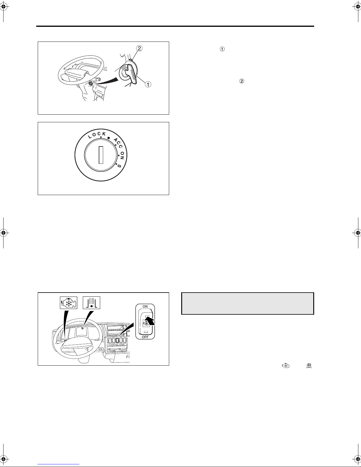
Cold start switch
When starting the engine in freezing temperatures,
or when you want to shorten the warm-up time or
boost interior heating during parking, press this
switch to ON.
When the switch is turned to ON, the exhaust brake
will be applied. This makes the engine warm up
quicker after start-up. Indicator lamps and
light up.
NOTE:
• Be sure to press the switch to OFF before start-
ing your vehicle.
• In cold-temperature environments, white smoke
in the exhaust gas may decrease for several
minutes after pressing the cold start switch ON,
then increase again after a while.

5-5
Engine idling control volume
CAUTION
• Be sure to set the engine idling control vol-
ume to the AUTO position during driving.
If you drive with the engine speed raised by
the volume, abrupt starting or premature
wear of the clutch may occur.
• Turn the engine control knob gently, as forc-
ing it could damage the internal mechanism.
• If the idling speed is set too low using man-
ual control, the engine may become excessively noisy. Make sure the idling speed is
correct.
NOTE:
If the engine speed is raised by the engine idling
control volume with the cold start switch set to the
ON position, black smoke may be produced. Before
turning on the cold start switch, be sure to set the
engine idling control volume to the AUTO position.
Z11729
Automatic control
The engine is warmed up with the speed being
automatically controlled according to the engine
coolant temperature. (The engine speed automatically decreases as the coolant temperature
rises.)
Manual control
Turn the knob counterclockwise to reduce the
engine speed.
Turn it clockwise to increase the engine speed.
The engine idling control knob should normally
be placed in the automatic control position.
Engine idling speed
575 to 625 rpm

5-6 Switches and controls
Z11775
Starting the engine
WARNING
• Do not warm up the engine in a garage or
other closed area. When starting the
engine or entering or leaving a garage, do
not run the engine for longer than is necessary as the accumulation of exhaust gas
in closed areas is very dangerous.
Exhaust emissions contain carbon monoxide (CO), which if breathed can cause
unconsciousness or death.
• If you smell exhaust gases inside the cab,
inspect the exhaust pipe and check
whether exhaust gases are leaking
through holes or cracks caused by corrosion or damage. If exhaust gases are leaking, have the exhaust pipe inspected by an
authorized dealer.
If exhaust gases that have leaked from the
exhaust pipe come into the cab, ventilate
the cab with fresh air by opening the windows fully or by opening the doors.
• Make sure that there are no flammables
such as dry grass under or behind the
parked vehicle, especially close to the
exhaust pipe. A fire could be started by the
heat from the engine or exhaust pipe.
• When you start the engine, be sure to sit in
the correct position on the driver’s seat to
wait for the engine to warm up. If you are
leaning out of the door window or otherwise incorrectly seated and the vehicle
suddenly moves, a serious accident could
occur.
CAUTION
• It is dangerous to push-start the engine
since, at the time of start, sufficient assist
power is not available for both braking and
steering. Only push-start the engine when it
is unavoidable.
• It is impossible to push-start an automatic
transmission vehicle, and attempting to do
so could damage the transmission.
• Do not use ether or other vapor compound
type starting aids. Use of such fluid on this
engine could result in serious damage.

5-7
NOTE:
• In cold weather, keep the accelerator pedal
depressed until the engine is running.
• Do not continue to turn over the starter for more
than 15 seconds as this could damage the
starter or wear down the battery.
• If you operate the starter continuously for 15
seconds and the engine still does not start, turn
the starter switch to the “ACC” position and wait
30 seconds before trying again to start the
engine.
• Do not rev the engine after it starts.
If you are depressing the accelerator pedal to
help start the engine and once the engine starts,
reduce the foot pressure on the pedal properly
to prevent the engine from running at excessively high speeds.
• If the engine does not start in cold weather,
check if the preheating circuit fuse has blown.
P. 13-10
• On a vehicle that has not been operated for a
long period, or after replacement of engine oil or
engine oil filter element, be sure to crank the
engine before turning it over. P. 5-9
Z11776
Z11777
1 Pre-starting steps
1. Pull parking brake lever or parking brake control
valve to fully apply the parking brake.
2. Manual transmission vehicle:
Place gearshift lever in the neutral position.
Automatic transmission vehicle:
Place range selector lever in the “P” position
<other than FM65F> or “N” position <FM65F>.
3. Turn the engine idling control volume to the
automatic control position.
Z11778

5-8 Switches and controls
NOTE:
• For safety, the engine in a manual transmission
vehicle cannot be started unless the gearshift
lever is in the neutral position.
• In an automatic transmission vehicle other than
FM65F, the engine cannot be started unless the
range selector lever is in “P” or “N” position. It is
safer to start the engine with the range selector
lever in the “P” position. Start the engine with the
range selector lever in the “N” position only
when absolutely necessary, for example, if the
engine stops while the vehicle is on a level
crossing.
• In an automatic transmission vehicle of the
FM65F, the engine cannot be started unless the
range selector lever is in the “N” position.
2 Starting procedure
1. Turn the starter key to the “ON” position.
NOTE:
If a buzzer sounds when the starter key is turned to
the “ON” position, activate the parking brake.
Should the buzzer still continue sounding with the
parking brake activated, the air tank pressure or the
brake fluid level is too low. P. 6-7, P. 6-8
Z00043
Z11779
Z02640
2. Check whether the indicator lamp illuminates or not.
• If the lamp does not illuminate:
With the clutch pedal depressed, turn the starter
switch to the “S” position to start the engine. You
need not depress the accelerator pedal.

Z00045
5-9
• If the lamp illuminates:
Wait until the lamp goes out. Pump the
accelerator pedal several times while waiting.
When the lamp goes out, turn the starter
switch to the “S” position to start the engine with
both the clutch pedal and accelerator pedal
depressed.
NOTE:
To start the engine in cold weather, press the cold
start switch to “ON”. This shortens the engine
warm-up time, but be sure to press this switch to
“OFF” before driving.
3 Starting the engine when vehicle has
been parked over an extended period
When a vehicle sits idle over an extended period of
time, its engine becomes oil starved and should be
cranked using the following method to distribute oil
throughout the engine:
CAUTION
• For safety, apply the parking brake fully and
chock the wheels to prevent the vehicle from
moving.
• Cranking the engine as described here is
essential for protection of the turbocharger.
1. Pull the parking brake lever or knob to fully
apply the parking brake.
2. Manual transmission vehicle:
Place the gearshift lever in the neutral position.
On automatic transmission vehicle other than
FM65F, place the range selector lever in the “P”
position.
On FM65F, place the range selector lever in the
“N” position.
3. Without pressing the accelerator pedal, turn the
starter switch to the “S” position and crank the
engine for about 15 seconds.
If the engine starts, release the starter key and
do not depress the accelerator pedal for roughly
15 seconds.

5-10 Switches and controls
4 Starting engine with the cab tilted
When you need to start the engine with the cab
tilted for inspection or servicing purposes, be sure
to observe the following safety precautions:
• Set the parking brake firmly, chock the wheels,
and take other necessary measures to prevent
the vehicle from moving.
• With a manual transmission vehicle, check that
the gear shift lever is in the neutral position.
With an automatic transmission vehicle other
than FM65F, check that the range selector lever
is in the “P” position.
With the FM65F automatic transmission vehicle,
check that the range selector lever is in the “N”
position.
• Place the starter switch in the “S” position to
start the engine.
Warming up the engine
Z11775
Do not drive the vehicle immediately after starting
the engine. Allow the engine to warm up at least
until the needle moves in the water temperature
gauge.
WARNING
• Do not warm up the engine in a garage or
other closed area. When starting the
engine or entering or leaving a garage, do
not run the engine for longer than is necessary as the accumulation of exhaust gas
in closed areas is very dangerous.
Exhaust emissions contain carbon monoxide (CO), which if breathed can cause
unconsciousness or death.
• If you smell exhaust gases inside the cab,
inspect the exhaust pipe and check
whether exhaust gases are leaking
through holes or cracks caused by corrosion or damage. If exhaust gases are leaking, have the exhaust pipe inspected by an
authorized dealer.
If exhaust gases that have leaked from the
exhaust pipe come into the cab, ventilate
the cab with fresh air by opening the windows fully or by opening the doors.
• Make sure that there are no flammables
such as dry grass under or behind the
parked vehicle, especially close to the
exhaust pipe. A fire could be started by the
heat from the engine or exhaust pipe.

5-11
CAUTION
Racing the engine immediately after starting
may cause rapid wear of cylinders and pistons,
leading to engine failure. Be sure to follow the
following warming up procedure.
NOTE:
• Immediately after starting, ignition is somewhat
harder to take place due to the low temperature
of the engine, which may cause knock, especially in cold regions.
• Idling the engine for long time wastes fuel, and
is therefore detrimental to environmental protection and resource conservation. So shut down
the engine whenever you leave the vehicle,
even for a short period.
After the engine has been idling for a relatively
long time, white smoke may be given off from
the muffler when driving off from a standstill and
accelerating. This is a normal effect of the catalytic converter that is located in the muffler, and
does not indicate any abnormality.
1. When the engine has started, remove your foot
from the clutch pedal. If you started the engine
with the accelerator pedal depressed, gradually
release the accelerator.
If the engine idling control volume is placed in
the automatic control position, it automatically
adjusts the engine speed.
Z11781
Z11782
Z11783
2. If you want to shorten the warm-up time, turn the
cold start switch to ON.
NOTE:
If the engine speed is raised by the engine idling
control volume with the cold start switch set to the
ON position, black smoke may be produced. Before
turning on the cold start switch, be sure to set the
engine idling control volume to the AUTO position.
3. Continue warming up the engine until the water
temperature gauge needle moves.

5-12 Switches and controls
4. If you placed the engine idling control volume in
the manual control position before starting the
vehicle, place it in the automatic control position.
Turn the cold start switch to OFF if the switch
was turned to ON in step 2.
Z11784
Stopping the engine
WARNING
• Never allow the vehicle to coast with the
engine stopped as braking may be ineffective and steering difficult when engine is
not running. This may also cause trouble
in the fuel injection system.
• The engine and exhaust pipe are
extremely hot just after stopping the vehicle. Avoid parking the vehicle where the
exhaust pipe could set fire to materials
such as dry grass.
Z11776
CAUTION
• Allow the engine to idle for at least 3 minutes
before stopping it. Not doing so could result
in an engine malfunction.
• The engine should only be stopped from an
idle. Stopping it at a high RPM could result in
an engine malfunction.
• After stopping the engine, do not leave the
starter switch in the “ON” or “ACC” position
since this could drain the battery. Turn the
switch to the “LOCK” position or to the position between the “ACC” and “LOCK” positions (marked with a “•”).
1. Apply the parking brake while depressing the
brake pedal.

Z11777
5-13
2. Manual transmission vehicle:
Place gearshift lever in the neutral position.
Automatic transmission vehicle:
Place range selector lever in the “P” position
<other than FM65F> or “N” position <FM65F>.
3. Allow the engine to idle for more than 3 minutes
before stopping it.
When the vehicle is in motion, engine parts
become extremely hot. This is particularly true
during uphill or high-speed driving. Therefore,
let the engine cool down sufficiently by allowing
it to idle for a time before stopping it.
Z11785
Z00056
Z11787
4. Turn the starter switch to the “ACC” position to
stop the engine.
Pedals
Accelerator pedal
Racing the engine also increases fuel consumption.
WARNING
If you use a floor mat, lay it correctly and
make sure it is suitable for the size of the
vehicle. It is dangerous for a floor mat to
cover the accelerator pedal or for floor mats
to be laid in multiple layers since the accelerator pedal may be prevented from returning
when released.

5-14 Switches and controls
Brake pedal
Use the brake pedal correctly. P. 7-7
WARNING
Do not allow the floor mat, gravel, or empty
beverage cans or bottles to get under the
brake pedal as they will interfere with brake
pedal movement.
Keep the floor free of any objects obstructive
to operation of the pedal. Mud, dust or floor
mat, if caught in the pedal, may also cause
dragging of brakes.
Clutch pedal
<Manual transmission vehicles>
Do not operate the vehicle with your foot on the
clutch pedal as doing so can shorten the service life
of the clutch. It may also cause the engine braking
and exhaust braking performance to deteriorate.
For details of clutch pedal usage when pulling away,
refer to “Precautions when setting the vehicle in
motion” on page 7-2.
For details of clutch pedal usage while driving, refer
to “Precautions for driving” on page 7-3.
Z11788
Gearshift lever
<Manual transmission vehicles>
CAUTION
• Shifting from a forward gear to the reverse
gear or vice versa, should be done only after
the vehicle has come to a complete stop.
When backing up, always double check to
make sure that there is nothing in your path.
• When the gearshift lever is in the neutral
position, never keep your hand on the lever,
as a forward or backward pressure resulting
from this practice could cause malfunction
of the transmission.
• When shifting, fully depress the clutch pedal
and then operate the gearshift lever. Otherwise, damage to the transmission may
result.
• The gear pattern is inscribed on gearshift lever.
• When the gearshift lever is placed in the reverse
“R” position, the backup lamps light up and the
backup buzzer sounds simultaneously.
• Refer to the following pages for instructions on
using the 9-speed transmission.

HIGH range
LOW range
Range selection lever
Z11789
5-15
9-speed transmission
<Manual transmission vehicles>
The 9-speed transmission has two speed ranges:
LOW and HIGH. The “LO” and reverse gears can
be used only in the LOW range, and the other gears
can be used in both the LOW and HIGH ranges.
1 Gearshift lever
The range selection lever on the gearshift lever
allows selection of the LOW and HIGH ranges.
The indicator lamp comes on when the LOW
range is selected, and the lamp comes on when
the HIGH range is selected.
Read the “Gearshifting” section for information on
appropriate use of the ranges.
Z08244
2Shift pattern
The shift pattern is indicated on the top of the gearshift lever knob.
LOW range: LO – 1 – 2 – 3 – 4 Reverse “R”
HIGH range: 5 – 6 – 7 – 8
N: Neutral position
3Gearshifting
Standing start
•
1. Select the LOW range with the range selection
lever.
2. Make sure the indicator lamp is illuminated.
3. Depress the clutch pedal fully.
4. Move the gearshift lever from the neutral position to the “LO” or 1st position.
5. Release the clutch pedal slowly and depress the
accelerator pedal.
CAUTION
The LOW range must be selected when the “LO”
gear is used. Make sure the indicator lamp
is illuminated before moving the gearshift lever
to the “LO” position.

5-16 Switches and controls
• Upshifts and downshifts
(LO
↔ 4th; 5th ↔ 8th)
Operate the gearshift lever and pedals in the same
way as with a standard manual transmission.
• Range changes from 4th to 5th
1. While driving in the 4th gear, move the range
selection lever to the HIGH range position.
2. Depress the clutch pedal fully.
3. Move the gearshift lever to the neutral position.
4. Make sure the indicator lamp is illuminated,
then move the gearshift lever to the 5th position.
5. Release the clutch pedal and depress the accelerator pedal.
• Range change from 5th to 4th
1. While driving in the 5th gear, move the range
selection lever to the “LOW” range.
2. Depress the clutch pedal fully.
3. Move the gearshift lever to the neutral position.
4. Make sure the indicator lamp is illuminated,
then move the gearshift lever to the 4th position.
5. Release the clutch pedal and depress the accelerator pedal.
CAUTION
• Range changes from LOW to HIGH and vice
versa take place when the gearshift lever
passes through the neutral position after the
range selection lever has been moved to the
HIGH or LOW position.
• Whenever you change the range, move the
range selection lever to the LOW or HIGH
position first and then move the gearshift
lever as desired.
• When the gearshift lever is in the neutral
position, never keep your hand on the lever,
as a forward or backward pressure resulting
from this practice could cause malfunction
of the transmission.
• Reversing
1. With the gearshift lever in the neutral position,
move the range selection lever to the LOW
range position. Make sure the indicator
lamp is illuminated.
2. Depress the clutch pedal fully.
3. Move the gearshift lever to the reverse position.
The backup lamp will illuminate and the buzzer
will sound.
4. Release the clutch pedal slowly and depress the
accelerator pedal.
5-17
CAUTION
• The LOW range must be selected when the
vehicle is reversed. Make sure the indicator lamp is illuminated before moving the
gearshift lever to the “R” position.
• Never move the range selection lever to the
HIGH position while reversing the vehicle.
The vehicle speed would be dangerously
high with the HIGH range selected.
• Shifting from a forward gear to the reverse
gear or vice versa, should be done only after
the vehicle has come to a complete stop.
When backing up, always double check to
make sure that there is nothing in your path.
• Skipshifting
You can skip gears when upshifting or downshifting
to a desired gear. With a downshift, first make sure
the engine speed is low enough for the engine not
to overrev.
Z11790
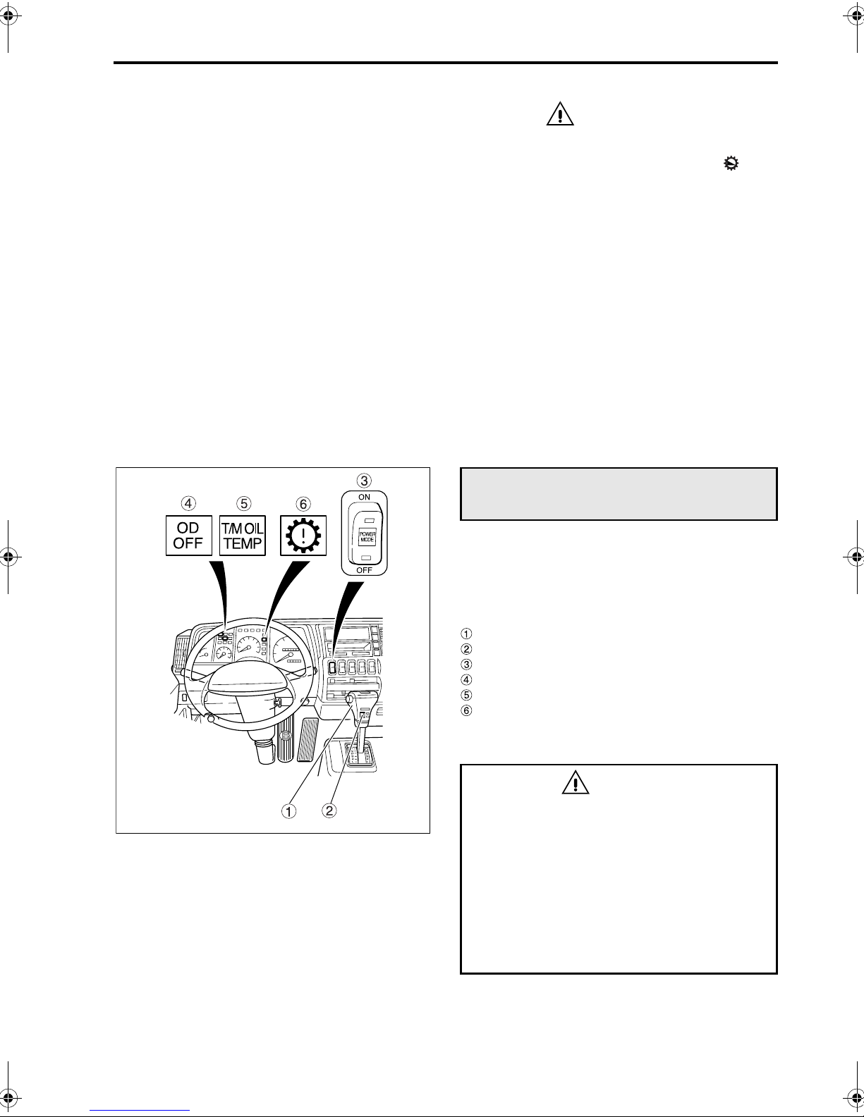
Allison automatic transmission
LCT 1000/2400 series
<All models except FM65F with automatic transmission>
Please refer to the attached Allison Operator’s Manual for instructions not covered in this Owner’s Manual.
Range selector lever
Overdrive switch
Power mode switch
Overdrive off indicator lamp
Transmission fluid temperature warning lamp
Transmission warning lamp
1 How to use the range selector lever
WARNING
• When shifting from the “P” or “N” position
to other positions, be sure to keep the
brake pedal depressed or set the parking
brake.
• Do not move the range selector lever to
the “D” or “R” position when the engine
speed is high during engine warm up,
operation of the air conditioner, or depression of the accelerator pedal. Shifting
under this condition is highly dangerous
as the vehicle will jerk.

5-18 Switches and controls
Button
The range selector lever is used to select gear
ranges.
Select lever positions carefully to ensure proper
engagement of each gear.
When the gearshift lever is placed in the reverse “R”
position, the backup lamps light up and the backup
buzzer, if provided, sounds simultaneously.
Push the button and move the lever.
Move the lever without pushing the button.
Z11791
NOTE:
• Before starting to move the vehicle forward or
backward, you must depress the brake pedal
and wait until the engine speed reaches a regular idling speed before placing the range selector lever in the “D” or “R” position.
If you try to move the range selector lever to the
“D” or “R” position while the engine is running
faster than a regular idling speed or the vehicle
is in motion, the safety system may cause the
transmission to remain in neutral. If this happens, a buzzer will sound and you must then
perform the range selector lever operation
again.
• To place the range selector lever in the “P” posi-
tion, proceed as follows. Depress the foot brake
pedal to bring the vehicle to a halt, then apply
the parking brake. Move the lever from either
the forward or reverse range, whichever the
gear is in at that time, to the “N” position. Then,
finally move the lever to the “P” position. If this
process is not followed, it may require great
effort to move the range selector lever out of the
“P” position and back to other ranges.
2 Overdrive switch
Pressing the switch to the down position will turn it
off and pressing it again to the up position will turn it
on.
The indicator lamp will light up when the switch
is pressed to the OFF position.
ON: Place the switch in this position for normal
driving. Make sure the switch is in this position during high-speed driving. When the
overdrive switch is ON, the transmission
will operate in the 5-speed mode, which
makes driving more economical.
OFF: Use this position for downhill driving requir-
ing engine braking and long uphill driving.
The transmission will operate in the 4speed mode.
Z11792

Z11793
Z10987
5-19
3 Power mode switch
A choice of two driving modes is available to suit the
road conditions and the load being carried.
Press the ON side of this switch to activate the
power mode. Pressing the OFF side of the switch
will cause the transmission to revert to the normal
mode.
The lamp inside the switch will light up when the
power mode is selected.
• Power mode
This is used when a powerful driving force is
needed, such as in mountainous areas, when
carrying heavy loads, and when overtaking
safely on expressways.
• Normal mode
This is used for normal driving, and provides a
smoother, quieter, and more economical ride.
4 If a warning lamp illuminates
Transmission fluid temperature warning
•
lamp
This lamp illuminates if the automatic transmission
fluid becomes excessively hot. If the lamp illuminates while the vehicle is in motion, pull over at the
nearest safe place, put the range selector lever in
the “P” position, and run the engine at slightly
higher than idling speed to cool down the transmission.
If the warning lamp goes out, it is safe to continue
driving.
If the warning lamp does not go out, or if it repeatedly lights up, you must have your vehicle repaired
by an authorized dealer.
While cooling the transmission, check the automatic
transmission for fluid leakage. If any leakage is
found, call an authorized dealer for repair.
Z10839
• Transmission warning lamp
• This lamp illuminates when there is something
wrong in the transmission’s electronic control
system.
If it illuminates when the starter key is moved to
the “ON” position, but then goes out after a few
seconds, this means the electronic control system is working properly.
If the lamp illuminates while the vehicle is moving, drive to a safe place and stop.
• If the electronic control system fails, the fail-safe
feature kicks in and the vehicle goes into backup mode. In this mode, the vehicle can still be
driven to a safe place. If it is not possible to shift
between gears, do it manually as follows to drive
the vehicle to a safe place.

5-20 Switches and controls
• Manually driving the vehicle to a safe place
If a failure in the electronic control system disables gear shifting, remove the 2 “A/T” fuses in
the sub-fuse box. This will enable driving using
the range selector lever as follows.
For the locations of the “A/T” fuses, refer to the
decal on the back of the glove box lid.
P. 1 3- 8
Range selector
lever position
PPark
RReverse
N Neutral
D Fixed in 3rd
3 Fixed in 3rd
2 Fixed in 3rd
L Fixed in 3rd
Corresponding range/
gear in manual mode
• Wait 10 seconds after stopping the engine, then
start it again. If the fault was only temporary, the
system may return to normal.
If the warning lamp does not go out, or if it keeps
illuminating from time to time, the system needs
repairing. Contact an authorized dealer.
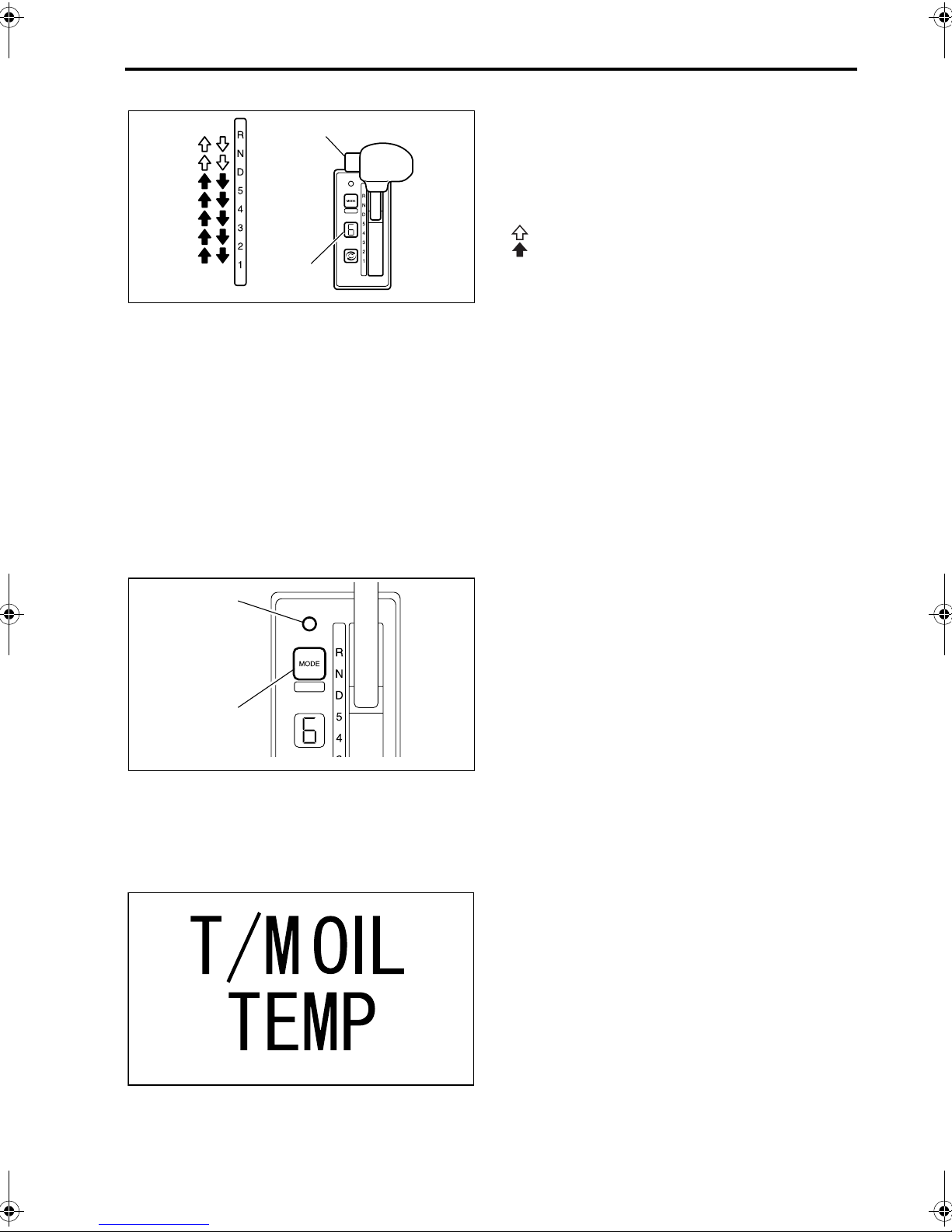
Allison automatic transmission
MD3060P series
Z11968
<FM65F model with automatic transmission>
Please refer to the attached Allison Operator’s Manual for instructions not covered in this manual.
Range selector lever
Digital display
Mode button
Mode indicator
Transmission oil temperature warning lamp
Transmission warning lamp
1 How to use the range selector lever
WARNING
• When shifting from the “N” position to
other positions, be sure to keep the brake
pedal depressed or set the parking brake.
• Do not move the range selector lever to
the “D” or “R” position when the engine
speed is high during engine warm-up,
operation of the air conditioner, or depression of the accelerator pedal. Shifting
under this condition is highly dangerous
as the vehicle will jerk.
5-21
Button
Digital
display
Z06630
The range selector lever is used to select gear
ranges. Select lever positions carefully to ensure
proper engagement of each gear.
When the gearshift lever is placed in the reverse “R”
position, the backup lamps light up and the backup
buzzer, if provided, sounds simultaneously.
Push the button and move the lever.
Move the lever without pushing the button.
• The digital display will indicate the selected
range.
NOTE:
Before starting to move the vehicle forward or backward, you must depress the brake pedal and wait
until the engine speed reaches a regular idling
speed before placing the range selector lever in the
“D” or “R” position.
If you try to move the range selector lever to the “D”
or “R” position while the engine is running faster
than a regular idling speed or the vehicle is in
motion, the safety system may cause the transmission to remain in neutral. If this happens, a buzzer
will sound and you must then perform the range
selector lever operation again.
Mode indicator
Mode button
Z06631
Z10987
2 Mode button
A choice of two driving modes is available to suit the
road conditions and the load being carried.
Pressing the mode button changes the mode back
and forth between Power mode and Normal mode.
When the transmission is in Power mode, the mode
indicator illuminates.
• Power mode
This is used when a powerful driving force is
needed, such as in mountainous areas, when
carrying heavy loads, and when overtaking
safely on expressways.
• Normal mode
This is used for normal driving, and provides a
smoother, quieter, and more economical ride.
3 If a warning lamp illuminates
•
Transmission fluid temperature warning
lamp
This lamp illuminates if the automatic transmission
fluid becomes excessively hot. If the lamp illuminates while the vehicle is in motion, pull over at the
nearest safe place, put the range selector lever in
the “N” position, and run the engine at slightly
higher than idling speed to cool down the transmission.
If the warning lamp goes out, it is safe to continue
driving.
If the warning lamp does not go out, or if it repeatedly lights up, you must have your vehicle repaired
by an authorized dealer.

5-22 Switches and controls
Z10839
While cooling the transmission, perform the following inspection:
1. Check that the electric fans on both sides of
vehicle are operating.
WARNING
Never touch the fan even if it is not turning.
The fan could suddenly start operating and
cause injury.
2. If the fan is not operating, check the fuse;
replace it if blown.
Check the oil cooler for mud or other dirt, and
clean it if necessary. P. 12-65
3. Check the automatic transmission for fluid leakage. If any leakage is found, call an authorized
dealer for repair.
• Transmission warning lamp
This lamp illuminates when there is something
wrong in the transmission’s electronic control system.
If it illuminates when the starter key is moved to the
“ON” position, but then goes out after a few seconds, this means the electronic control system is
working properly.
If the lamp illuminates while the vehicle is moving,
drive to a safe place and stop.
NOTE:
Do not stop the engine until the vehicle is in a safe
place. If the engine is stopped, the gear will automatically go into the neutral, and the vehicle will not
be able to move.
Wait 10 seconds after stopping the engine, then
start it again. If the fault was only temporary, the
system may return to normal.
If the warning lamp does not go out, or if it keeps
illuminating from time to time, the system needs
repairing. Contact an authorized dealer.
Parking brake
WARNING
Do not use the parking brake when driving
except in an emergency, link if the service
brakes have failed. Such use of the parking
brake may make the vehicle spin or, at worst,
roll over. It may also cause faults in vehicle
components.

Z02468
5-23
1 Parking brake lever
<All models except FM657F>
• To set for parking
The parking brake is activated when the parking
brake lever is pulled. At the same time, indicator
lamp lights up.
• To release
To release the parking brake, press the button at
the end of the lever while raising the latter slightly.
Then, with the button pressed, return the lever to its
original position.
• How to park P. 7-12
Z02812
CAUTION
• Illumination of indicator lamp does not
necessarily indicate that the parking brake
has been fully activated. Be sure to pull the
lever all the way.
• Before putting the vehicle in motion, check
that indicator lamp is not illuminated.
• Do not drive with the parking brake applied.
Doing so will not only degrade the parking
brake performance but also cause the parking brake to overheat, possibly resulting in a
fire.
2 Parking brake control valve
<FM65F>
• To set for parking
Pull knob of the parking brake control valve; the
rear wheels are blocked and the indicator lamp
lights up.
• To release
Make sure that the warning lamp is not illuminated. Push the knob and confirm that the indicator lamp goes out.
Parking
• How to park P. 7-12
Release
Z11796

5-24 Switches and controls
CAUTION
• Brake line air pressure may temporarily drop
after a release of the parking brake. Always
check the air pressure before driving.
• When the warning lamp is illuminated,
the brakes are not completely released even
if the knob is pressed. Driving under such a
condition may cause the brakes to drag.
If the air pressure in the parking brake system
falls due to factors like damage to the brake
line, the brake might not release even when the
brake control valve knob is pressed.
P. 1 3- 14
Combination switch
Z11797
Z05251
1 Arrangement of switches
Lighting switch
Turn signal lamp switch
Passing signal/dimmer switch
Auto cruise cancel switch and set/
resume switch P. 5-29
Wiper and washer switch
Hazard warning lamp switch
Exhaust brake switch
2 Lighting switch
The lighting switch can be used with the starter
switch in any position.
Turning the knob at the end of the lever controls the
illumination of lamps as follows:
Clearance/side marker
Switch
position
OFF Off On*
lamps, identification lamps,
parking lamps, rear combina-
tion lamps, backup lamps,
license plate lamp, and meter
illumination lamps
On On*
On On
Headlamps
*: Illuminated by daytime running light system
CAUTION
Keeping the headlamps on for a long period
without the engine running can drain the battery, making the engine impossible to start.

HIGH
LOW
PASS
Z11798
Z05252
5-25
NOTE:
Even when the vehicle is operated with the lighting
switch in the “OFF” or position, the daytime
running light system causes the low-beam headlamps to be lit. (The headlamps are dimmer than
when activated using the lighting switch.) The
indicator lamp is also lit. When the parking brake is
applied or the engine is stopped, the headlamps
and the indicator lamp go off.
3 Passing signal/dimmer switch
Passing signal
Pulling the lever up activates the high beams.
Use this to flash a signal when overtaking
another vehicle.
Dimmer
With the headlamps illuminated, pushing the
lever down activates the headlamp high beams
and pulling it back to the original position reactivates the low beams. When the high beams are
on, indicator lamp lights up.
Z05253
Z11799
4 Turn signal lamp switch
Turn signal
•
Moving the lever forward or backward activates
the corresponding turn signal causing it to flash.
At the same time, the corresponding indicator
lamp or flashes.
When the steering wheel is returned to the neutral position after a right or left turn, the switch
automatically moves back to the neutral position
and the lamp stops flashing. After making a
moderate turn, however, the switch will sometimes not return automatically. In this case, put
the switch in the neutral position by hand.
• Lane changer
Lightly pushing the lever forward or backward
causes the corresponding turn signal lamp to
flash while the lever is held in this position.
5 Hazard warning lamp switch
The hazard warning lamps may be used as a warning to other vehicles when you suddenly find it necessary to stop your vehicle in emergencies.
The lamps can flash in any of the starter switch
positions.
Pulling the lever up causes all turn signal lamps to
flash simultaneously. At the same time, indicator
lamps start flashing. Pulling the lever
another time causes the lamps to stop flashing.

5-26 Switches and controls
CAUTION
The battery may be discharged and the engine
impossible to restart if the hazard warning
lamps are operated for an extended period of
time.
6 Exhaust brake switch
WARNING
Using the exhaust brake on a wet, frozen,
snow-covered, or otherwise slippery road
surface when the vehicle is lightly loaded or
not loaded can cause the tires to slip on the
road surface, resulting in a skid. Do not use
the exhaust brake on slippery road surfaces.
Z11800
The exhaust brake enhances engine braking. Use it
as an auxiliary braking means on downhill stretches
or during high-speed driving.
NOTE:
Do not keep the exhaust brake switch in the activation position at all times. Frequent use of the
exhaust brake reduces fuel economy. Move the
exhaust brake switch between the activation and
non-activation positions as necessary according to
road and traffic conditions.
Pushing the lever forward activates the exhaust
brake. While the exhaust brake activated, indicator
lamp stays illuminated.
The exhaust brake is temporarily deactivated if any
of the actions listed below are performed. It will
become active again as soon as the vehicle returns
to its previous state.
• Depressing the accelerator pedal
• Depressing the clutch pedal <manual transmis-
sion models>
• Moving the gearshift lever or selector lever to
the neutral position
• Operating the anti-lock brake system
• Driving at a very low speed or reversing
<automatic transmission models>
NOTE:
In an FM65F automatic transmission vehicle, activating the exhaust brake while the vehicle is running in 6th gear causes the transmission to shift
down to 5th gear.

5-27
7 Wiper and washer switch
WARNING
• Do not operate the windshield wipers or
washer when you are servicing your vehicle with the front panel opened as the
wiper link inside is potentially dangerous.
• In cold weather, warm the windshield with
the heater before operating the washer
since washer fluid could otherwise freeze
onto the windshield and obstruct your
vision.
CAUTION
• Operating the wipers when the windshield is
dry damages the windshield glass. Always
squirt the glass with washer fluid before
operating the wipers.
• Never operate the wipers and washer with
the wiper arms raised. The arms could be
damaged.
• Do not operate the wipers when the rubber
parts of the wiper blades are frozen onto the
windshield or otherwise stuck to the windshield. The wiper blades could get damaged,
and the wiper motor could fail.
• When the wipers are not used for a long
time, dust, sand, and other substances can
collect between the wiper blades and windshield. Clean the wipers before using them.
Otherwise, the windshield may get
scratched.
• Operating the washer continuously for more
than 20 seconds or when there is no fluid in
the reservoir could burn out the washer
motor.
• Rotating the grip at the end of the lever activates
the windshield wipers in one of the following
three modes:
INT: Wipers operate intermittently at 3 to 5 sec-
ond intervals.
LO: Wipers operate at a slow speed.
HI: Wipers operate at a rapid speed.
• To activate the windshield washer, push the
button at the end of the lever; the washer fluid
will be sprayed and the wiper will operate one or
two strokes automatically.
• Refill the washer fluid reservoir if the fluid level
is low. P. 12-60
Z12423

5-28 Switches and controls
Z11824
Van body dome light switch
This switch operates the lighting inside the van
body. With the starter switch in the “ON” position,
operate the van body dome light switch to turn the
van body interior lighting on or off. An indicator lamp
comes on in the switch when it is in the “ON” position.
CAUTION
Leaving the van body interior lighting on for an
extended period without the engine running can
drain the battery.
Brightness control switch
Z11825
Z11826
Use the brightness control switch to adjust the
intensity of the meter cluster illumination lamps.
With the meter cluster lamps on, press and hold
either side of the switch to set the lamps to your
desired brightness, then release the switch.
To brighten: Press upper side of the switch
To darken: Press lower side of the switch
Power take-off switch
This switch is used to engage and disengage the
power take-off device that transfers engine power
through the transmission.
CAUTION
• To engage power take-off, turn on the switch
only after depressing the clutch pedal.
• Never attempt to engage the power take-off
while the vehicle is in motion.
• Disengage the power take-off before driving
the vehicle. It is dangerous to drive the vehicle with the power take-off engaged because
vehicle-mounted equipment that is driven
through the power take-off could operate.
Also, the vehicle-mounted equipment could
fail.
• Pressing switch to the ON position with the
clutch pedal depressed engages the power
take-off. When the power take-off is engaged,
the lamp inside the switch and the indicator
lamp light up.
• To disengage the power take-off, turn the switch
OFF.

5-29
Cruise control
Cruise control memorizes any desired speed above
the speeds given below and maintains that speed
automatically without operating the accelerator
pedal. It is especially useful for freeway driving that
involves almost no chances of pulling over and
stopping.
Speeds above which cruise
control functions
Manual transmis-
sion vehicle
Automatic trans-
mission vehicle
NOTE:
For the sake of safety, do not use the cruise control
in the following driving conditions:
Approx. 40 km/h (25 mph)
Approx. 57 km/h (35 mph)
• In heavy traffic which does not allow sufficient
vehicle to vehicle distance
• On roads with sharp turns or poor visibility
• On icy, snow-covered, or otherwise slippery
roads
• Steep downhill road
The vehicle speed may become higher than the set
speed on a steep downhill road. Stop using the
cruise control if this occurs.
Main switch
This switch is used to activate and deactivate
the cruise control function. The lamp inside the
switch illuminates when the cruise control is on.
WARNING
For safety, turn off the main switch when the
cruise control is not in use.
Z11827
Cancel switch
Used to terminate cruise-control operation.
SET/RESUME switch
SET position:
Used to set a desired speed and to reduce the
set speed.
RESUME position:
Used to increase the set speed and to return to
a previously memorized speed.
Cruise control indicator lamp
If the cruise control is activated, this lamp illuminates during driving.
NOTE:
The indicator lamp will light up when the starter
switch is turned to the ON position and the engine is
not running. It will go out in a few seconds if there
are no problems.

5-30 Switches and controls
1 To set a desired speed
1. Check that the exhaust brake switch is in the
OFF position. If the switch is in the ON position,
place it in the OFF position.
Press the ON side of the main switch. The lamp
inside the switch will illuminate.
Z11828
2. Depress the accelerator pedal until the desired
speed is reached.
Z11829
Z11830
3. When the desired speed is reached, turn the
“SET/RESUME” switch to the “SET” position.
The indicator lamp will illuminate indicating
that the cruise control is activated. Now the
desired speed is memorized, so release the
accelerator pedal. The vehicle will run maintaining that speed automatically.
NOTE:
• When setting the desired speed, the gearshift
lever in a manual transmission vehicle must be
in the 4th or higher gear position and in an automatic transmission vehicle, the selector lever
must be in the “D” position.
• Before pressing the ON side of the main switch
to set a desired speed, make sure the exhaust
brake switch is in the OFF position. You will not
be able to set the speed if the exhaust brake
switch is in the ON position. When driving with
the cruise control active, exhaust braking can be
used as usual, but the cruise control function will
be deactivated while exhaust braking is being
used.

Z11831
5-31
2 To increase the set speed in cruise con-
trol mode
•
By using the resume switch
Turn the “SET/RESUME” switch to the “RESUME”
position. The vehicle will accelerate. When the
desired speed is reached, release the switch. The
vehicle will cruise at the new, higher speed.
• By using the accelerator pedal and speed set
switch
1. Use the accelerator pedal to reach the desired
speed.
Z11829
Z11832
Z11832
2. When the desired speed is reached, turn the
“SET/RESUME” switch to the “SET” position.
The vehicle will cruise at the current speed.
3 To decrease the set speed in cruise con-
trol mode
Turn the “SET/RESUME” switch to the “SET” position. The vehicle will decelerate. When the desired
speed is reached, release the switch. The vehicle
will cruise at the new, lower speed.

5-32 Switches and controls
4 To accelerate temporarily in cruise con-
trol mode
Depress the accelerator pedal as you do in normal
accelerating. When the pedal is released, the vehicle will cruise at the set speed again.
Z11829
5 Automatic deactivation of the cruise
control
The cruise control is deactivated automatically and
the indicator lamp also goes out in the following
conditions:
• When the cancel switch is pushed
• When the brake pedal is depressed
• When the exhaust brake is activated
• When the clutch pedal is depressed
<Manual transmission vehicles>
• When the gearshift lever is placed in the neutral
position <Manual transmission vehicles>
• When the range selector lever is placed in the
“N” position <Automatic transmission vehicles>
Z13616
Z11833
CAUTION
In an automatic transmission vehicle, placing
the range selector lever in the “N” position temporarily deactivates the cruise control. However, such practice is dangerous during driving
because engine braking will no longer be possible. It will also cause malfunction of the automatic transmission.
6 To reactivate the temporarily deacti-
vated cruise control
To reactivate the cruise control, turn the “SET/
•
RESUME” switch to the “RESUME” position.
The indicator lamp will illuminate again and
the vehicle will resume running at the set speed.
• To reactivate the cruise control with a different
speed specified, turn the “SET/RESUME” switch
to the “SET” position when the vehicle reaches
your desired speed. The indicator lamp will
light up, and the vehicle will continue running at
the set speed.
NOTE:
Under any of the following conditions, you cannot
resume the set speed by performing the above
operation. In these situations, perform the speed
setting procedure from the beginning.
• The vehicle speed is lower than 30 km/h (18
mph).
• The 3rd or lower speed gear is selected.

Z13617
5-33
7 To deactivate the cruise control
Press the OFF side of the main switch.
CAUTION
• Consult an authorized dealer if you wish to
install a radio transmitter/receiver equipment. Proper operation of the cruise control
cannot be ensured if this equipment is
installed in an inappropriate location or is
incorrectly adjusted.
• If the (red) or warning lamp illumi-
nates, turn off the cruise control main switch
and have the vehicle inspected by an authorized dealer.
• When there is a problem with the engine
control system, the cruise control cannot be
used.
Air suspension height control
Z12401
<Rear air suspension vehicles>
It is possible to lower the cargo bed while the vehicle is stationary. This function can be used with the
starter switch in “ON” or “ACC” position.
NOTE:
• The height control switch should be turned off
when adjustment of the cargo bed height is not
being performed.
• Compressed air will be required to move the
cargo bed back to driving height. It is important,
therefore, that the engine be started up.
• Extended periods of use while the engine is not
running can be the cause of flat batteries.
1 Lowering the cargo bed
1. Set the starter switch in “ON” or “ACC” position.
2. Apply the parking brake securely. In a manual
transmission vehicle, set the gearshift lever in
neutral. In an automatic transmission vehicle,
set the range selector lever in “P” or “N” range.

5-34 Switches and controls
3. Push the DOWN side of the height control
switch to lower the cargo bed.
Z11836
NOTE:
• The system will prevent the cargo bed from low-
ering if the vehicle is in any of the following conditions.
• The parking brake is not applied.
• The starter switch is not in the “ON” or “ACC”
position.
• The gear shift lever is not in “NEUTRAL”
(vehicle with manual transmission).
• The range selector lever is not in the “P” or
“N” range (vehicle with automatic transmission).
• If either of the following operations are per-
formed during the lowering process, the cargo
bed will automatically return to driving height.
The height control switch will automatically
return to OFF.
• The parking brake is released.
• The starter switch is turned to positions other
than “ON” or “ACC”.
• The gear shift lever is moved out of “NEU-
TRAL” (vehicle with manual transmission).
• The range selector lever is moved out of the
“N” or “P” range (vehicle with automatic
transmission).
Z11837
2 Returning the cargo bed to driving
height
Push the OFF side of the height control switch to
automatically return the cargo bed to driving height.
NOTE:
Be sure to push the OFF side of the height control
switch before the vehicle is driven.
WARNING
The air suspension height control system
uses compressed air from the brake system.
It is important to confirm that the warning
lamp is not lit and that no buzzer is sounding
before the vehicle is driven.

6-1
6. Instruments and warning lamps
Arrangement of instruments and warning lamps . . . . . . . . . . . . . . . . . . . . . . . . . . . . . . . . . . . . . . . . . . . . 6-2
Speedometer . . . . . . . . . . . . . . . . . . . . . . . . . . . . . . . . . . . . . . . . . . . . . . . . . . . . . . . . . . . . . . . . . . . . . . . 6-2
Tachometer . . . . . . . . . . . . . . . . . . . . . . . . . . . . . . . . . . . . . . . . . . . . . . . . . . . . . . . . . . . . . . . . . . . . . . . . 6-2
Air pressure gauge . . . . . . . . . . . . . . . . . . . . . . . . . . . . . . . . . . . . . . . . . . . . . . . . . . . . . . . . . . . . . . . . . . . 6-3
Water temperature gauge . . . . . . . . . . . . . . . . . . . . . . . . . . . . . . . . . . . . . . . . . . . . . . . . . . . . . . . . . . . . . 6-3
Fuel gauge . . . . . . . . . . . . . . . . . . . . . . . . . . . . . . . . . . . . . . . . . . . . . . . . . . . . . . . . . . . . . . . . . . . . . . . . . 6-4
Warning/indicator lamps . . . . . . . . . . . . . . . . . . . . . . . . . . . . . . . . . . . . . . . . . . . . . . . . . . . . . . . . . . . . . . 6-4

6-2 Instruments and warning lamps
Z11838
Z02091
Arrangement of instruments and
warning lamps
Speedometer
Tachometer
Air pressure gauge
Water temperature gauge
Fuel gauge
Warning/indicator lamps
Speedometer
• The speedometer indicates vehicle speed in
MPH and km/h.
The outer numbers denote MPH, and the inner
numbers denote km/h.
• The odometer indicates in miles the total dis-
tance covered by the vehicle. Black figures represent one-tenth of miles.
Z11839
Tachometer
• The tachometer indicates engine speed in revo-
lutions per minute.
• The red zone indicates that engine is over-
reved. Reduce the vehicle speed sufficiently so
that the needle does not enter this range during
downhill driving or downshifting.
CAUTION
The term “overrev” refers to an operational
state of the engine in which it turns at an RPM
exceeding the maximum limit. Persistent overrevving could lead to an engine failure.
• Tachometer with overrevving alarm
<Vehicles with 9-speed transmission>
When the engine speed exceeds 3‚400 rpm, warning lamp lights up and a buzzer sounds.

Z11840
6-3
Air pressure gauge
The air pressure gauge indicates the amount of air
pressure in the air tank. Red zone indicates that air
pressure is either too low or too high.
If the needle deflects into the red zone , warning
lamp lights up and a buzzer sounds. The outer
needle indicates the rear brake line air pressure,
while the inner needle indicates the front brake line
air pressure. Whenever the warning lamp illuminates, pull off the road as soon as you can safely
do so, and let the engine rotate at a speed in the
intermediate range until air pressure builds to a normal level. If air pressure fails to build or takes longer
to return to a normal level than it should, or again, if
the needle indicates a high pressure over 130 lb./
2
in
, call an authorized dealer.
WARNING
Never operate the vehicle if warning lamp
is lit up as brakes may be inoperative.
Z11841
Water temperature gauge
This gauge indicates the temperature of the engine
coolant.
With the engine running normally, the needle should
be in the center of the gauge.
If the needle points in the red zone , the engine
has overheated. The warning lamp will light up
and a buzzer will sound simultaneously. Should this
occur, pull off the road as soon as you can safely do
so and let the engine rotate at a speed above idling
speed to cool it down.
If the vehicle has an air conditioner, switch it off.
P. 13-7
CAUTION
• Be sure to stop the engine only after letting it
run at a speed slightly above the idling RPM
until the coolant cools down. Turning off the
engine immediately after stopping will cause
the coolant temperature to rise quickly and
may cause the engine to seize up.

6-4 Instruments and warning lamps
Z00541
Fuel gauge
The fuel gauge indicates the amount of fuel still
remaining in the fuel tank.
F: Full
E: Empty
When the needle approaches the “E” mark, refuel
as soon as possible. P. 1-5
CAUTION
The fuel injection system may fail if the engine
stops due to lack of fuel.
NOTE:
The fuel gauge needle constantly follows the fuel
level; it remains set even when the starter switch is
in the “ACC” or “LOCK” position, indicating the fuel
level at that time.
The reading may, however, change slightly over a
long period even if the actual fuel level does not
change.
Warning/indicator lamps
1 Arrangement of warning/indicator lamps
The illustrations below show the standard arrangement of the warning and indicator lamps. Some
lamps may not be included depending on vehicle
specifications.
CAUTION
The red warning lamps, if illuminated, warn you
of vehicle component failures and possible danger of accident. Never drive the vehicle while a
red warning lamp is illuminated. If any of them
light up, stop the vehicle as soon as it is safe to
do so and make checks for locating the cause. If
necessary, have your vehicle repaired by an
authorized dealer.

6-5
Lamp
symbol
Z11842
Warning/indicator lamp If illuminated Ref. page
Charge warning lamp Problem in battery charging system 6-9
Open door warning lamp Door not completely closed 3-2
Cab tilt lock warning lamp Cab is tilting or incompletely locked 12-8
Low coolant level/engine overheating
warning lamp
Engine oil pressure/clogged oil filter
warning lamp
Engine oil level warning lamp
Brake warning lamp
<other than FM65F>
• Coolant is at an excessively low level (*)
• Engine is overheating (*)
• Excessively low engine oil pressure (*)
• Clogged oil level (*)
Engine oil level is correct (when oil level
check switch is operated)
• Brake fluid at an excessively low level (*)
• Excessive brake shoe clearance (*)
6-7
12-38
6-9
12-31
12-20
6-7
Air pressure warning lamp Low air pressure in air tank (*) 6-8
Transmission fluid temperature
warning lamp
<Automatic transmission vehicles>
Transmission warning lamp
<Automatic transmission vehicles>
Automatic transmission fluid
excessively hot
Fault in electronic control circuitry of automatic transmission
5-19
5-21
5-19
5-22
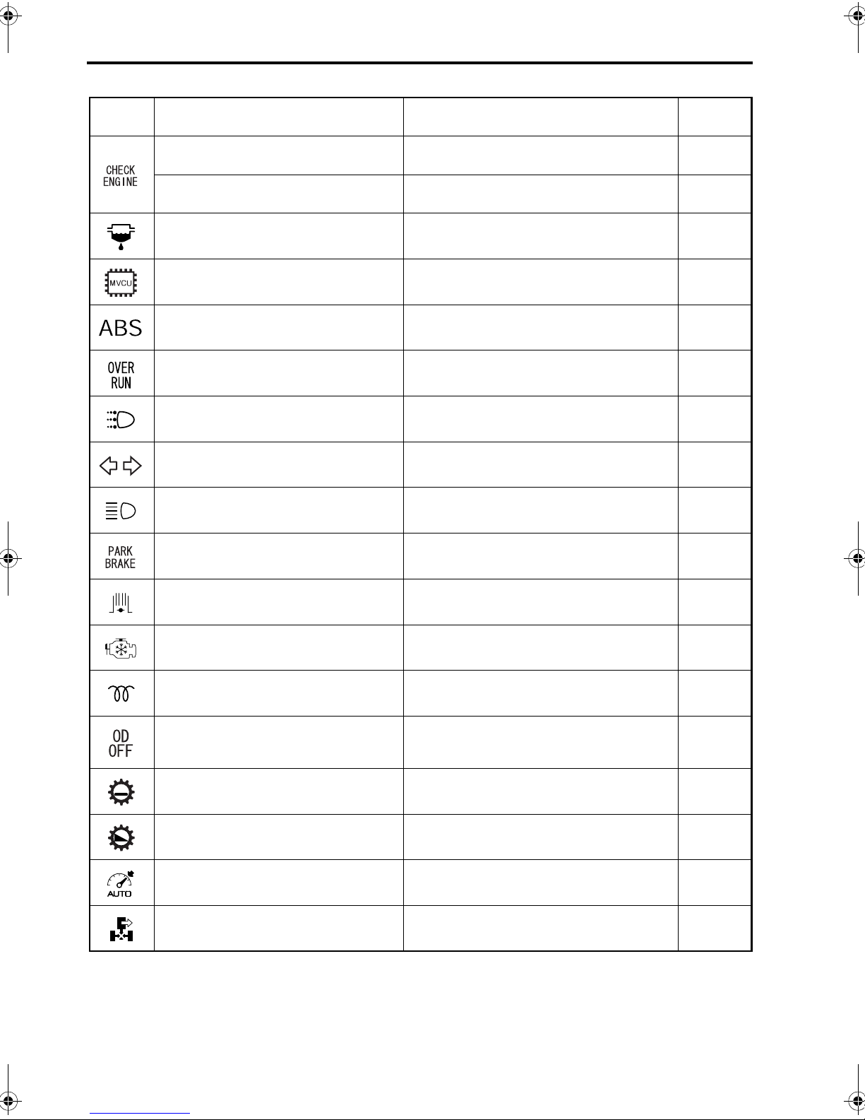
6-6 Instruments and warning lamps
Lamp
symbol
Warning/indicator lamp If illuminated Ref. page
(Red) Engine control warning lamp
(Amber) Engine control warning lamp
Fuel filter warning lamp Water level in fuel filter is high 12-37
Vehicle control warning lamp Malfunction in electrical control system 6-11
ABS warning lamp
Overrunning warning lamp <9-speed
manual transmission vehicles>
Daytime running light indicator lamp
Turn signal indicator lamp Turn signals activated 5-25
Headlamp high beam indicator lamp Headlamp high beams illuminated 5-25
Fault in electronic control circuitry of fuel
injection system
Fault in electronic control circuitry of fuel
injection system (functionality reduced)
Malfunction in anti-lock brake system
(ABS)
Engine speed exceeding 3,400 rpm (*) 6-2
Headlamps (low-beam) illuminated by
daytime running light system
6-10
6-10
8-4
5-25
Parking brake indicator lamp Parking brake activated 5-22
Exhaust brake indicator lamp Exhaust brake activated 5-26
Cold start indicator lamp Cold start switch ON 5-4
Engine preheat indicator lamp Engine being preheated 5-8
Overdrive OFF indicator lamp <Allison
automatic transmission LCT1000/2400
series>
High gear indicator lamp <9-speed
manual transmission vehicles>
Low gear indicator lamp <9-speed
manual transmission vehicles>
Cruise control indicator lamp Cruise control activated 5-29
Power take-off indicator lamp Power take-off engaged 5-28
Overdrive switch OFF 5-18
Transmission in HIGH range 5-15
Transmission in LOW range 5-15
NOTE:
(*): Warning lamps illumination of which is accompanied by a buzzer sounding.

Z10486
6-7
2 Low coolant level/engine overheating
warning lamp
•
This lamp illuminates and a buzzer sounds if
there is insufficient engine coolant or if the
engine overheats.
NOTE:
The buzzer stops sounding when the vehicle is
stopped and the parking brake is activated.
• If the water temperature gauge’s needle enters
the red zone, the engine has overheated. Pull
off the road as soon as it is safe to do so and run
the engine slightly faster than idling speed until it
cools down and then take necessary action
against overheating. P. 13-7
WARNING
Driving with an overheated engine can damage the engine or even cause a fire.
CAUTION
Be sure to stop the engine only after letting it
run at a speed slightly above the idling RPM
until the coolant cools down. Turning off the
engine immediately after stopping will cause the
coolant temperature to rise quickly and may
cause the engine to seize up.
• If the water temperature gauge’s needle does
not point to the red zone, there is insufficient
engine coolant. Check the coolant level and add
the coolant.
WARNING
Driving with insufficient coolant will cause
overheating, which can damage the engine
and even cause a fire.
3 Brake warning lamp
<Other than FM65F>
The brake warning lamp will light up and a buzzer
will sound if the brake fluid in the brake fluid reservoir tank falls below the predetermined level, or if
the brake shoe clearance exceeds the predetermined value.
Z10912
WARNING
Never continue driving if the warning
lamp is illuminated. The brakes are dangerously ineffective and could cause an accident.

6-8 Instruments and warning lamps
NOTE:
With the starter switch in the “ON” position and the
engine not running, the warning lamp will illuminate. It is normal if the lamp will go out when the
engine is started.
• If the warning lamp stays illuminated
1. Check the level of the fluid in the brake fluid reservoir tank.
2. If fluid level is found to be low, check for leaks.
3. If leaks are detected, call an authorized dealer.
4. If fluid leaks are not detected, fill with fluid to the
normal level.
5. If the lamp illuminates even when the brake fluid
level is correct or after fluid has been added,
have the brakes inspected by an authorized
dealer as soon as possible.
• If the warning lamp illuminates when the
brake pedal is depressed
Brake shoe clearance (the clearance between the
brake drum and brake shoe lining) is adjusted automatically. If the brake performance has deteriorated
and warning lamp illuminates together with the
buzzer sounding when the brake pedal is
depressed, the brake shoe clearance has become
excessive. Have the brakes inspected by an authorized dealer as soon as possible.
Z10913
CAUTION
Although the brake shoe clearance is adjusted
automatically, unexpected failure of the automatic adjuster can result in excessive clearance
and poor brake performance. Regularly check
the brake shoe clearance and how much the
brake lining is worn to confirm that the automatic adjuster is functioning correctly.
4 Air pressure warning lamp
This lamp lights up and the buzzer sounds when the
brake air pressure has dropped to an unsafe level
at which sufficient braking performance is not
ensured. Pull off the road as soon as it is safe to do
so, and perform the following checks.
WARNING
• The brakes become completely inopera-
tive when the compressed air in the air
tank is exhausted.
• When the warning lamp is illuminated, the
brakes are dangerously sluggish and
could cause an accident. Never continue
driving with the vehicle in this condition.
NOTE:
With the starter switch in the “ON” position and the
engine not running, the warning lamp will illuminate. It is normal if the lamp will go out if the engine
is started.

Z10484
6-9
1. Let the engine run at an intermediate RPM until
the warning lamp goes out.
2. Check piping and its connections for air leaks.
3. If the lamp does not go out or goes on again
soon after it has gone out, the system must be
repaired. Call an authorized dealer.
5 Charge warning lamp
The charge warning lamp lights up when the starter
switch is turned to the “ON” position and goes out
as soon as the alternator starts charging the battery
after the engine has turned over.
The lamp also lights up if a problem occurs in the
battery charging system while the engine is running.
If this occurs, pull off the road as soon as it is safe to
do so, and perform the following checks.
NOTE:
• The warning lamp will light up if the starter
switch is turned to the “ON” position when the
engine is not running. It goes out after the
engine is started if there are no problems.
• If the alternator is malfunctioning, the and
warning lamps may light up simultaneously
with the warning lamp.
• The buzzer stops sounding when the vehicle is
stopped and the parking brake is activated.
1. Check for a broken V-belt. Also check belt tension. P. 12-44
2. Check for a blown high-current fuse in the battery charging circuit. If blown, replace with a new
one. P. 13-8
3. If both the above checks have turned out normal, the problem is probably in the battery
charging system. Call an authorized dealer.
Z10476
6 Engine oil pressure/clogged oil filter
warning lamp
The engine oil pressure/clogged oil filter warning
lamp lights up when the oil filter element is clogged
or the engine oil pressure becomes abnormally low.
Pull off the road as soon as it is safe to do so, stop
the engine, and perform the following inspection.
NOTE:
The warning lamp will light up when the starter
switch is turned to the “ON” position and the engine
is not running. It goes out after the engine is started
if there are no problems. In cold climates, the warning lamp may remain illuminated for a while after
starting the engine due to high viscosity of the
engine oil.
• If the lamp lights up without buzzer sounding
The oil filter element is clogged. Replace the element as early as possible. P. 12-31
CAUTION
Continued driving with the lamp illuminated
may cause engine to seize up. Replace the element as early as possible.

6-10 Instruments and warning lamps
Z11795
• If the lamp lights up and buzzer sounds
The engine oil pressure is abnormally low.
1. Check the engine oil level. Add if insufficient.
P. 12 -1 9
2. Check the engine for any trace of oil leaks.
3. If the oil level is normal and there is no trace of
oil leaks, there is probably a problem in the lubricating system. Call an authorized dealer.
CAUTION
Never continue driving with the lamp illuminated. The engine could seize up.
NOTE:
The buzzer stops sounding when the vehicle is
stopped and the parking brake is activated.
7 Engine control warning lamp
Illumination of red lamp
•
Illumination of the red engine control warning lamp
indicates a fault in the electronic control circuitry of
the fuel injection system. The engine output may be
limited depending on the location of the fault. If the
lamp illuminates, stop the vehicle at a safe place.
Place the starter switch in “ACC” or “LOCK” position
for 5 seconds or longer to reset the computer and
then restart the engine. If the lamp stays off, there is
no problem. If the lamp illuminates again, stop the
engine and contact the nearest authorized dealer.
NOTE:
The warning lamp will light up when the starter
switch is turned to the “ON” position and the engine
is not running. It goes out after the engine is started
if there are no problems.
• Illumination of amber lamp
Illumination of the amber engine control warning
lamp indicates a fault in the electronic control circuitry of the fuel injection system that has caused
the system’s functionality to decrease. If the lamp
illuminates, stop the vehicle at a safe place. Place
the starter switch in “ACC” or “LOCK” position for 5
seconds or longer to reset the computer and then
restart the engine. If the lamp stays off, there is no
problem. If the lamp illuminates again, have your
vehicle inspected at an authorized dealer in the earliest opportunity.
NOTE:
The warning lamp will light up when the starter
switch is turned to the ON position and the engine is
not running. It goes out after the engine is started if
there are no problems.

Z11859
6-11
8 Vehicle control warning lamp
The vehicle control warning lamp lights up when
problems occur in the vehicle’s electrical control
system. If it lights up, pull off the road as soon as it
is safe to do so.
Place the starter switch to the “ACC” or “LOCK”
position for more than five seconds, then restart the
engine. If the warning lamp goes out, there are no
problems. If it remains on, have your vehicle
inspected by an authorized dealer as soon as possible.
NOTE:
The warning lamp will light up when the starter
switch is turned to the “ON” position and the engine
is not running. If it goes out after a few seconds,
there are no problems.


7-1
7. Starting and driving
Precautions when setting the vehicle in motion . . . . . . . . . . . . . . . . . . . . . . . . . . . . . . . . . . . . . . . . . . . . . 7-2
Precautions for driving . . . . . . . . . . . . . . . . . . . . . . . . . . . . . . . . . . . . . . . . . . . . . . . . . . . . . . . . . . . . . . . . 7-3
Precautions when driving on a manual transmission vehicle . . . . . . . . . . . . . . . . . . . . . . . . . . . . . . . . . . . 7-5
Precautions when driving on an automatic transmission vehicle . . . . . . . . . . . . . . . . . . . . . . . . . . . . . . . . 7-5
Tips for improving fuel economy . . . . . . . . . . . . . . . . . . . . . . . . . . . . . . . . . . . . . . . . . . . . . . . . . . . . . . . . 7-6
Braking . . . . . . . . . . . . . . . . . . . . . . . . . . . . . . . . . . . . . . . . . . . . . . . . . . . . . . . . . . . . . . . . . . . . . . . . . . . . 7-7
On uphill and downhill roads . . . . . . . . . . . . . . . . . . . . . . . . . . . . . . . . . . . . . . . . . . . . . . . . . . . . . . . . . . . 7-9
On rough roads and in bad weather . . . . . . . . . . . . . . . . . . . . . . . . . . . . . . . . . . . . . . . . . . . . . . . . . . . . 7-10
Parking . . . . . . . . . . . . . . . . . . . . . . . . . . . . . . . . . . . . . . . . . . . . . . . . . . . . . . . . . . . . . . . . . . . . . . . . . . . 7-12
Loading cargo . . . . . . . . . . . . . . . . . . . . . . . . . . . . . . . . . . . . . . . . . . . . . . . . . . . . . . . . . . . . . . . . . . . . . 7-14

7-2 Starting and driving
Z11316
Precautions when setting
the vehicle in motion
• Do not carry containers of fuel or spray cans in
the cabin.
WARNING
Carrying fuel in the cabin is extremely dangerous because an increase in the cabin temperature could cause fuel vapor to catch fire
or cause the container to rupture.
• Do not attach any decorative panels or similar
items to the windshield.
WARNING
Attaching a decorative panel or similar item
to the windshield could impede driving and
visibility. In addition, any suction cup on
such an item could cause a fire by acting as a
lens.
• Check the immediate area around the vehicle,
using mirrors as necessary: there should be no
persons or obstacles under, in front of, on either
side, or behind the vehicle. Be particularly careful when backing up. If you cannot see behind
the vehicle in the mirrors, get out of the vehicle
and check that it is safe to start moving the vehicle.
• Check that none of the red warning lamps are
illuminated. The warning lamp will go out
when the parking brake is released.
• Fully release the parking brake.
• In a manual transmission vehicle, put it in the
first gear and set it in motion carefully. When
pulling away, avoid racing the engine and suddenly engaging the clutch. Sudden starts place
undue strain on the vehicle and should be
avoided. Also, avoid slipping the clutch for
extended periods since this can damage it.
• In an automatic transmission vehicle, depress
the brake pedal and move the range selector
lever out of the “P” or “N” position. If the engine’s
idling speed is too high, selecting the “D” or “R”
ranges may make the vehicle lurch. Normalize
the engine’s idling speed before pulling away.
Running the air conditioner, if fitted, raises the
engine’s idling speed and may make the vehicle
pull away faster than expected.
NOTE:
If the range selector lever is operated with the
engine speed too high, the intended gear may not
be selected properly. If this happens, a buzzer will
sound.

Z01410
7-3
Precautions for driving
Observe the following precautions while driving.
Should you notice anything unusual about the vehicle, immediately stop the vehicle in a safe place and
inspect the relevant sections to find the cause of the
trouble. If you are unable to identify the cause of the
trouble or unable to do the repairs yourself, call an
authorized dealer.
• Do not stop the engine while the vehicle is mov-
ing.
WARNING
Never place the starter switch in any position
other than the “ON” position while operating
the vehicle.
If you turn the starter switch to the “ACC”
position, the engine will stop. This is highly
dangerous.
If the engine stops during driving:
• The compressed air used to enhance brak-
ing ceases to be generated. This could significantly reduce the effectiveness of the
brakes. Also, the exhaust brake ceases to
function.
• The power steering system becomes inop-
erative, rendering steering dangerously
sluggish.
• The electrical circuits of the warning
lamps, meters, etc. become inoperative,
causing electric components to malfunc-
tion.
Removing the starter key causes the steering
wheel to lock, making it impossible to steer
the vehicle.
• Should the engine stall while the vehicle is in
motion, do not panic. Simply depress the brake
pedal to slow the vehicle, and pull off the road
as soon as it is safe to do so.
• When any of the red warning lamps light up or a
buzzer sounds, pull the vehicle off the road as
soon as it is safe to do so and take the necessary measures. Contact an authorized dealer if
the cause of the problem is unclear or if the
problem requires complex repair work.
P. 6 -4
• Avoid making sharp turns and braking hard
except in emergencies. Doing so during highspeed driving could cause the vehicle to tip over.
• Avoid accelerating sharply on slippery roads
since this could make the tires slip and impair
directional stability.
• If you notice a strange noise, vibration, or smell,
or if steering or braking feels unusual, pull the
vehicle off the road as soon as it is safe to do so
and check for the source of the trouble.

7-4 Starting and driving
Z01413
• When driving on narrow streets or when making
a turn, keep in mind that the tracking of the front
and rear inner wheels is different, and also
make sure of rearward safety using the rearview
mirrors.
• Remember that the mirrors protrude from the
vehicle body. Be careful not to hit pedestrians
and obstructions with the mirrors when driving
on narrow roads.
Looking at the mirrors while driving causes your
line of vision to move significantly. Be sure to
keep paying attention to safety ahead of the
vehicle.
• Continuous high-speed driving burdens the
engine and other vehicle parts. Allow yourself
enough time that you do not need to push the
vehicle too hard.
• Perform your pre-operation checks with particu-
lar care when you expect to drive at high
speeds.
When continuously driving at high speeds, your
sense of speed may become dull. Pay constant
attention to your speed, and maintain an adequate distance from the preceding vehicle.
• If a tire bursts or gets punctured while you are
driving at high speed, do not panic. Keep a firm
grip on the steering wheel and gradually reduce
your speed. Stop the vehicle in the nearest safe
place. Do not brake sharply. Braking sharply
would be dangerous because the steering wheel
would be pulled to one side with great force.
• Do not keep the steering wheel turned to the
right or left stop for more than 10 seconds as
doing so could lead to a failure of the power
steering system.
• When driving at high speeds in the rain, it some-
times happens that the tires ride on a film of
water and lose contact with the road surface.
This is known as “hydroplaning”. If this should
happen, you will lose control of both steering
and braking. Therefore, be sure to maintain
moderate speeds on rainy days.
The hydroplaning can easily occur if tire tread is
worn to the point where the tread pattern is very
shallow.
• Using the exhaust brake on a wet, frozen, snow-
coverd, or otherwise slippery road surface when
the vehicle is lightly loaded or not loaded can
cause the tires to slip on the road surface,
resulting in a skid. Do not use the exhaust brake
on slippery road surfaces.
• Do not use a mobile telephone while driving. if
you wish to use a mobile telephone, first stop
the vehicle in a safe place. Using a mobile telephone while driving could distract your attention
from the vehicle and from the vehicle and from
the road ahead, resulting in an accident.
• Operate the radio and other items of equipment
in the cab when the vehicle is stationary. It is
dangerous to operate such items of equipment
or use a carphone (other than a hands-free
type) while driving.

Z11317
7-5
• Do not allow a child to touch the driver’s controls
and other equipment. A child’s interference
could cause a fault or accident.
Precautions when driving on a
manual transmission vehicle
• Avoid slipping the clutch excessively. Partially
depressing the clutch pedal while the vehicle is
in motion causes the clutch to slip and shortens
the service life of the clutch.
• Avoid suddenly releasing the clutch pedal since
this places undue stress on the vehicle and
shortens the service life of the clutch.
• Do not operate the vehicle with the clutch
disengaged or the gearshift lever in neutral.
Doing so will render the engine braking and
exhaust brake features ineffective, forcing you
to rely only on the service brakes and overusing
them in the process.
• Before shifting down, wait for the tachometer
needle to drop below 1‚600 rpm (1,800 rpm on
9-speed transmission vehicles) or decelerate
until the vehicle speed comes within the next
gear’s range. Not shifting down in this manner
could cause the engine to overrev.
NOTE:
“Overrev” refers to an operating state of the engine
in which it rotates at an RPM higher than the recommended maximum RPM. Overrevving the engine
could lead to an engine failure.
Precautions when driving on an
automatic transmission vehicle
• Select the “D” range for normal driving. Other
than FM65F, it is also possible to pull away
using the range selector lever in the same way
as a manual gearshift lever, starting in “L”, then
upshifting position by position to “D”.
On FM65F, it is also possible to pull away using
the range selector lever in the same way as a
manual gearshift lever, starting in “1”, then
upshifting position by position to “D”.
• Do not push the range selector lever into the “N”
position while the vehicle is in motion. This
would make engine braking and exhaust braking
impossible and force you to overuse the service
brakes. It could also damage the transmission.
• For safety, the transmission will automatically
refuse to shift down if the vehicle is moving too
fast. Decelerate sufficiently by depressing the
brake pedal before you can manually select a
lower speed range.
7-6 Starting and driving
Z11318
• If you stop the vehicle momentarily, for example,
at a red light, keep the brake pedal firmly
depressed. If you must wait for longer than
expected, select the “N” or “P” range (“N” range
on FM65F) and activate the parking brake.
• If you stop temporarily when driving uphill,
depress the brake pedal and activate the parking brake. Do not attempt to stop the vehicle
from rolling backwards with the accelerator
pedal.
Tips for improving fuel economy
Observe the following precautions to achieve maximum fuel economy and to extend tire life.
• Continue warming up the engine only to the
point at which the water temperature gauge
needle begins to move.
• Avoid racing the engine as doing so not only
wastes fuel but also harms the engine.
• Avoid sudden starts, sudden acceleration, and
sudden braking.
• When accelerating, do not allow the tachometer
needle to approach the red zone before changing gears; instead, change gears before engine
speed reaches a high RPM.
• Once cruising speed has been reached, select
the appropriate gear so that the engine will
rotate around the maximum torque generating
RPM (1‚400 rpm). Moreover, unnecessary
acceleration and deceleration wastes fuel.
• Do not keep the exhaust brake switch in the
activation position at all times. Frequent use of
the exhaust brake reduces fuel economy. Move
the exhaust brake switch between the activation
and non-activation positions as necessary for
road and traffic conditions.
• Always keep the air pressure in tires correctly
adjusted.
• Try to load cargo in a way that minimizes wind
resistance. P. 7-14
• Be sure to perform the pre-operational checks
and periodic inspections.
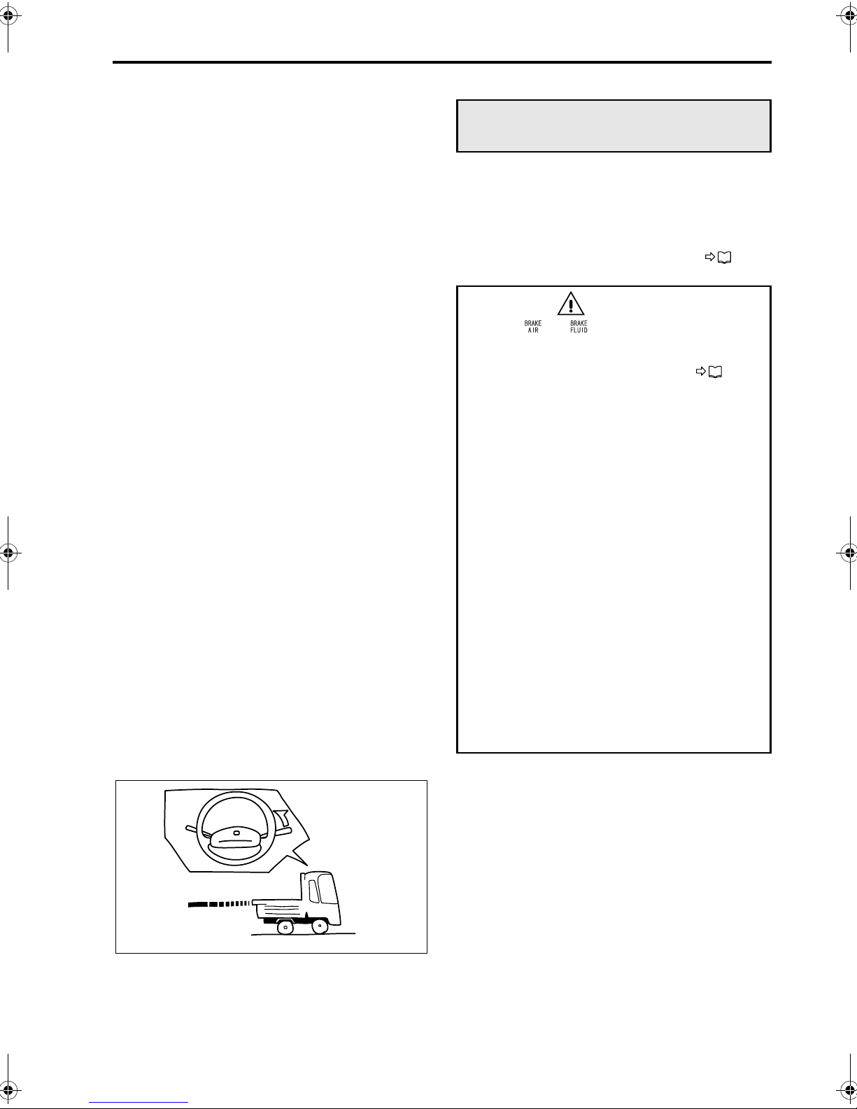
7-7
Braking
Applying even a light pressure to the brake pedal
provides powerful braking. Therefore, do not step
hard on the brake pedal except in emergencies.
When driving downhill, use engine braking as well
as exhaust braking in combination with the foot
brake. P. 7-9
WARNING
• If the or warning lamp illuminates
while the vehicle is in motion, stop at the
nearest safe place and identify the prob-
lem. P. 6-5
• If you release the brake pedal completely,
the vehicle will coast past the point at
which you wish to come to a halt.
• Do not pump the brake pedal as doing so
reduces the air pressure, which in turn
could reduce braking power.
• Using the exhaust brake on a wet, frozen,
snow-covered, or otherwise slippery road
surface when the vehicle is lightly loaded
or not loaded can cause the tires to slip on
the road surface, resulting in a skid. Do
not use the exhaust brake on slippery road
surfaces.
• Sudden braking will wear down tires and
could cause malfunctions in other sec-
tions of the vehicle.
Sudden braking could also result in an
injury due to shocks.
• Do not use the parking brake when driving
except in an emergency, like if the service
brakes have failed. Such use of the park-
ing brake may make the vehicle spin or, at
worst, roll over. It may also cause faults in
vehicle components.
1. The distance needed for braking varies with
speed, load weight, and road conditions. Make
effective use of engine braking and exhaust
braking to decelerate sufficiently before applying
the brakes.
NOTE:
Engine braking is a braking effect realized when the
accelerator pedal is released during vehicle operation. The lower the transmission gear, the more
powerful the engine braking.
Z11864

7-8 Starting and driving
2. Depress the brake pedal halfway when you are
nearby the place at which you wish to stop.
Z05577
3. Slowly release the pedal (half or one-third of the
stroke which you have used until then).
Z05578
Z11865
4. Just before reaching the point at which you wish
to come to halt, depress the pedal again very
slightly to stop the vehicle.

Z11320
Z11321
7-9
On uphill and downhill roads
1 Uphill roads
Downshift early when the speed begins to drop
•
to minimize the load on the engine.
• With an automatic transmission vehicle, down-
shifting can be performed either with the range
selector lever or by depressing the accelerator
pedal hard. If you depress the accelerator pedal
to maintain a constant speed when driving
uphill, the transmission may shift down and the
engine speed increase.
2 Downhill roads
If you are going to drive down a steep road or a
•
road with a long downhill grade, test the service
brake and exhaust brake in advance to make
sure that they are functioning well.
• Place the vehicle in the gear used when driving
uphill and use engine braking and exhaust
brake to help slow the vehicle. Never drive
downhill at high speeds.
If your vehicle is equipped with an automatic
transmission, leaving the range selector lever in
the “D” position will result in insufficient engine
braking, causing the vehicle to speed up too
much. Add engine braking as required by shifting down the gears.
Other than FM65F:
Shift down to “3”, “2” or “L” position. Use the service brakes to prevent engine overrev when
shifting to “2” or “L” position.
FM65F:
Shift down to “5”, “4”, “3”, “2” or “1” position. Use
the service brakes to prevent engine overrev
when shifting to “2” or “1” position.
• On slippery roads, avoid sudden engine braking
since this could cause a skid.
• Never coast downhill with the gearshift lever in
neutral (manual transmission vehicles) or the
range selector lever in the “N” position (automatic transmission vehicles). Doing so makes
both engine braking and exhaust brake inoperative, which in turn excessively burdens the service brakes. This also causes the brakes to
overheat and the brake linings to wear out prematurely.
In an automatic transmission vehicle, this can
also cause damage to the transmission.
• Avoid overusing the service brakes as the
resultant overheating could cause undesirable
vapor lock (other than FM65F) and fading, both
of which contribute to poor braking.

7-10 Starting and driving
NOTE:
• “Vapor lock” refers to the condition in which the
brake system overheats, causing the brake fluid
to boil and form bubbles that weaken hydraulic
pressure, resulting in poor braking.
• “Fading” refers to the condition in which the
brake linings overheat to the point where friction
with the brake drum is significantly reduced.
This also results in poor braking.
• First decelerate the engine sufficiently before
downshifting.
Downshifting more than two gears at a time or
downshifting at a high engine speed could
cause the engine to overrev.
Generally speaking, you should decelerate to
roughly 1‚600 rpm (1,800 rpm on 9-speed transmission vehicles) before downshifting.
For safety in an automatic transmission vehicle,
the transmission will automatically refuse to shift
down if the vehicle is moving too fast. Depress
the brake pedal to decelerate.
NOTE:
“Overrev” refers to an operating state of the engine
in which it rotates at an RPM higher than the recommended maximum RPM. Overrevving the engine
could lead to an engine failure.
Z11323
On rough roads and in bad weather
• Use a low gear and try to drive at a constant
speed when driving on gravel roads or muddy
roads.
• Do not race the engine when attempting to
move out of mud. Racing the engine is useless
and even worsens the condition as the spinning
wheels will make ruts deeper. Instead, place
thick waste cloth, gravel or the like under tires,
and engage the 1st and reverse gears alternately or, in an automatic transmission vehicle,
select the “D” and “R” positions alternately to
move the vehicle back and forth until you can
drive out.
When shifting from “D” or “R” or vise versa,
release the accelerator pedal to lower the
engine speed to idle.
CAUTION
Do not operate an automatic transmission in
this way for more than 5 minutes since it causes
the automatic transmission fluid to heat up rapidly.

7-11
• Drive very slowly on bumpy roads and try to
avoid bumps to prevent bottoming out of the
undercarriage.
If the muffler strikes a rock or other obstacle, its
catalyst or other internal elements may be damaged. Have it checked by an authorized dealer.
• Avoid sudden steering and sudden braking on
roads which are slippery from rain. Conditions
are especially dangerous just after it begins to
rain. Use engine braking and the exhaust brake
together with the wheel brakes to decelerate.
Note, however, that sudden engine braking can
cause a skid. Drive at a speed at which you can
stay comfortably in control of the vehicle.
• Brake performance may deteriorate when the
vehicle is driven through puddles or washed and
if water enters the brake drums. If this happens,
drive slowly while paying careful attention to surrounding traffic and keeping light pressure on
the brake pedal to dry the brake shoes and
drums.
• If you cannot avoid driving the vehicle into water
(for example, when the road is covered with
water because of torrential rain), first check the
depth of the water. If water gets into the engine,
it can cause engine damage. After driving
through water, check whether water has entered
the high-current fuse box. If water has entered
the high-current fuse box, remove the water and
have the vehicle inspected by an authorized
dealer. Water in the high-current fuse box could
cause a short circuit that results in a fire.
• In fog, drive carefully at low speeds, paying
attention to the center line and the vehicle
ahead of you.
• When driving in snow or on frozen roads, use
tire chains or snow tires and drive at moderate
speeds. Avoid sudden braking and sharp turns.

7-12 Starting and driving
Z11324
Z01422
Parking
WARNING
• Park the vehicle on the flattest available
surface.
Avoid parking on slopes.
When you cannot avoid parking on a
slope, apply chocks to the wheels. You
can further improve safety by leaving the
steering wheel turned so the vehicle will
roll toward an obstacle (for example, a
curbstone) in the unlikely event of movement.
• The engine and exhaust pipe are
extremely hot immediately after the vehicle has been driven. Do not park the vehicle in any place where there is dry grass,
waste paper, or other flammable material.
• Always stop the engine before sleeping in
the cabin. You could otherwise cause an
accident by unintentionally moving the
accelerator pedal or shift lever while sleeping. Also, you could suffer carbon-monoxide poisoning from exhaust gases if the
vehicle is parked in a closed space.
• Never leave lighters, cans of carbonated
drink, and spectacles in the cabin when
parking the vehicle in hot sunshine. The
cabin will become extremely hot, so lighters and other flammable items may catch
fire and unopened drink cans (including
beer cans) may rupture. The heat may also
affect plastic spectacle lenses and other
spectacle parts that are made of plastic.
For example, the coating on the lenses
may crack and the lenses themselves may
become deformed.
• Do not open the door suddenly when get-
ting out of the vehicle. This is dangerous,
as the door may obstruct the passage of
vehicles, motorcycles, bicycles, or pedestrians coming from behind the vehicle.
Always use the mirrors to check that it is
safe to open the door.

7-13
1. Depress the brake pedal to bring the vehicle to a
complete halt.
2. Parking procedures vary depending on the type
of transmission used on the vehicle. Proceed as
follows.
• On a vehicle with manual transmission,
move the gear shift lever to the “NEUTRAL”
position and apply the parking brake.
• On a vehicle with automatic transmission
(excluding FM65F), apply the parking brake
and then operate the range selector lever as
follows.
Move the lever from the forward or reverse
range, whichever the vehicle is in at that
time, to the “N” position, and then set the
lever to the “P” position. If this process is not
followed, it may require great effort to move
the range selector lever out of the “P” position and back to other ranges.
CAUTION
Do not park the vehicle only by setting the range
selector lever to the “P” position. Be sure to
also apply the parking brake at the same time.
• On a vehicle with automatic transmission
(FM65F), apply the parking brake and then
set the range selector lever to the “N” position.
WARNING
Illumination of the indicator lamp does
not necessarily mean that the parking brake
is sufficiently activated. Always activale fully
the parking brake.
3. Stop the engine by turning the starter switch to
the “ACC” position. P. 5-12
4. To help prevent theft and needless consumption
of electricity from the battery, be sure to remove
the starter key and lock the doors.
CAUTION
• Leaving the starter switch in the “ON” posi-
tion or “ACC” position for an extended
period may drain the battery.
• Be sure to turn off all lights after parking to
prevent drainage of the battery.
5. If parking on a slope is unavoidable, block the
wheels securely with chocks and take other necessary measures to prevent the vehicle from
moving.

7-14 Starting and driving
7,935 lbs.
23,735 lbs.
Z11869
15,800 lbs.
Z02404
Loading cargo
1 Do not overload the vehicle.
Overloading places undue stress on the vehicle
•
and shortens its service life.
The vehicle is designed to perform best when
loaded within its Gross Vehicle Weight Rating
(GVWR) and within its front and rear Gross Axle
Weight Ratings (GAWRs). Try not to exceed
these ratings.
• The vehicle’s GVWR, front GAWR, and rear
GAWR are listed on the VIN plate on the upper
section of driver’s door.
NOTE:
Loading to a weight almost equal to a total of the
front and rear GAWRs may exceed the GVWR. For
example, a vehicle with a GVWR of 23‚000 lb.
(10‚430 kg) has a front GAWR of 7,935 lb. (3‚600
kg) and a rear GAWR of 15,800 lb. (7‚165 kg).
Added together, the GAWRs total 23,735 lb.
(10,765 kg), thus exceeding the GVWR. Be sure
neither the GAWRs nor GVWR are exceeded.
Z11325
WARNING
• Overloading the vehicle can damage the
vehicle and make safe driving difficult. For
safety, never overload.
• The GVWR and GAWRs pertain to the max-
imum load the vehicle can physically
carry. Please also abide by state and
regional loading limit requirements.
• Do not carry passengers in the cargo area
while the vehicle is in motion.
2 How to load cargo
Improperly loaded cargo not only is unstable but
also may result in uneven weight distribution which
could damage the cargo deck and frame.
WARNING
• When roping up cargo or covering it with a
tarpaulin, make sure that neither the rope
nor the end of the tarpaulin hang down
between the cab and the cargo deck as a
loosely hanging rope or tarpaulin could
catch fire from the engine heat.
• When spreading the tarpaulin, take care
not to let it cover or be drawn into the
engine air intake duct.
• When loading heavy cargo, take adequate
measures to stop it from slipping. Also
use wire to secure it.

Z11326
7-15
• Place the cargo evenly on deck.
• If cargo is piled high, the vehicle is at risk of roll-
ing over upon being hit with a side wind or making a turn.
• If you place supports under the cargo, position
them at equal intervals.
• Use suitable supports when loading long
objects. Avoid supporting long objects only with
the gate and the rear edge of the cargo deck.
• To prevent cargo from falling, strap it down
securely and cover it with a tarpaulin. Secure
the tarpaulin ends neatly so they do not flap.
 Loading...