

Page 1

HARDWARE MANUAL
F940GOT-SWD-E/LWD-E
Page 2

F940GOT-SWD-E/LWD-E
Foreword
• This manual contains text, diagrams and explanations which will guide the reader in the
correct installation and operation of the communication facilities of FX series.
• Before attempting to install or use the communication facilities of FX series this manual
should be read and understood.
• If in doubt at any stage of the installation of the communication facilities of FX series
always consult a professional electrical engineer who is qualified and trained to the local
and national standards which apply to the installation site .
Page 3

F940GOT-SWD-E/LWD-E
F940GOT-SWD-E/LWD-E
HARDWARE MANUAL
Manual number : JY992D77901
Manual revision : D
Date : February 2000
i
Page 4

F940GOT-SWD-E/LWD-E
Guidelines for the safety of the user and protection of the F940GOT-SWD-E/LWD-E
This manual provides infor mation for the installation and use of the Graphic Operation Terminal F940GOT.
The manual has been written to be used by trained and competent personnel. The definition of such a person
or persons is as follows;
a ) Any engineer who is responsible for the planning, design and construction of automatic equipment
using the product associated with this manual should be of a competent nature , (tr ai ned and qualified
to the local and national standards required to fulfill that role). These engineers should be fully aware
of safety with regards to automated equipment.
b ) Any commissioning or service engineer must be of a competent nature, trained and qualified to the
local and national standards required to fulfill that job. These engineers should also be trained in the
use and maintenance of the completed product. This includes being completely familiar with all associated documentation for the said product. All maintenance should be carried out in accordance with
established safety practices.
c ) All operators of the compliance product should be trained to use that product in a safe and coordi-
nated manner in compliance to established safety practices. The operators should also be familiar
with all documentation which is connected with the actual operation of the completed equipment.
Note:
The term ‘completed equipment’ refers to a third party constructed device which contains or uses the
product associated with this manual.
ii
Page 5

F940GOT-SWD-E/LWD-E
Note’s on the symbology used in this manual
At various times through out this manual certain symbols will be used to highlight points of information which
are intended to ensure the users personal safety and protect the integrity of the equipment. Whenever any of
the following symbols are encountered, its as sociated note must be read and unders tood. Each of the symbols used will now be listed with a brief description of its meaning.
Hardware warnings
1 ) Indicates that the identified danger
2 ) Indicates that the identified danger
3 ) Indicates a point of further interest or further explanation.
Software warnings
1 ) Indicates special care must be taken when using this element of software.
2 ) Indicates a special point of which the user of the as sociate softw are element should be a ware.
WILL
POSSIBLY
cause physical and property damage.
cause physical and property damage.
3 ) Indicates a point of interest or further explanation.
iii
Page 6

F940GOT-SWD-E/LWD-E
Memo
iv
Page 7

F940GOT-SWD-E/LWD-E
CONTENTS
1. INTRODUCTION...................................................................................1-1
1.1 Outline of product................................................................................................1-2
1.2 Product configuration...........................................................................................1-8
1.3 System configuration.........................................................................................1-14
2. Installation, Wiring and General Specifications.....................................2-1
2.1 Installation of main body......................................................................................2-1
2.2 Wiring of power supply........................................................................................2-4
2.3 Functions of operation keys and connectors.......................................................2-9
2.4 Outside dimensions...........................................................................................2-12
2.5 General specificationsl ......................................................................................2-13
2.6 Connection to personal computer......................................................................2-15
2.7 CPU port connection .........................................................................................2-18
2.8 Computer link port connection (MELSEC A Series)..........................................2-26
2.9 Connection to SYSMAC C Series .....................................................................2-29
2.10 Connection to FLEX-PC N Series .....................................................................2-32
2.11 Connection by general-purpose communication ...............................................2-35
3. Startup...................................................................................................3-1
3.1 Startup procedure................................................................................................3-2
3.2 Operation environment setting ............................................................................3-5
4. Extension Module...... ... .. ..................... ... ..................... .. ...................... ..4-1
4.1 Data transfer adaptor...........................................................................................4-1
v
Page 8

F940GOT-SWD-E/LWD-E
5. Maintenance..........................................................................................5-1
5.1 Outline of maintenance........................................................................................5-1
5.2 Replacement of battery .......................................................................................5-3
5.3 Replacement of backlight....................................................................................5-5
6. Troubleshooting.....................................................................................6-1
6.1 Power indication..................................................................................................6-1
7. Additional Functions (in Ver3.00 or later)..............................................7-1
7.1 Applicable Versions and Models .........................................................................7-1
7.2 Connection to MELSEC QnA Series PC.............................................................7-2
7.3 Connection to SLC 500 Series............................................................................7-3
7.4 Connection to Bar Code Reader .........................................................................7-5
7.5 Screen Hard Copy Function................................................................................7-7
7.6 Additional Function in Alarm History Display.......................................................7-8
7.7 Specification of Ten-Key Window Initial Display Position....................................7-8
8. Additional Functions (in V3.10 or later) .................................................8-1
8.1 Applicable Versions and Models .........................................................................8-1
9. Additional Functions (in V4.00 or later) .................................................9-1
9.1 Applicable Versions and Models .........................................................................9-1
Note to User
This manual describes installation, wiring and the specifications of the F940GOT.
For handling and operating procedures of the F940GOT main body, refer to the
F940GOT Operation Manual
offered separately.
vi
Page 9

F940GOT-SWD-E/LWD-E
1. INTRODUCTION
This section describes the product configuration and the system configuration of the graphic
operation terminal.
Confirm various functions of each unit.
INTRODUCTION 1.
1-1
Page 10

F940GOT-SWD-E/LWD-E INTRODUCTION 1.
FX or
A Series PLC
Program
connector
GOT main body
1.1 Outline of product
The graphic operation termin al (which may be hereafter
abbreviated as "GOT") is attached on the panel face of a
control panel or an operation pane l, and connected to a
program connector in an FX or A Series programmable
controller (which may be hereafter abbreviated as "PLC")
(except the A0J2) inside the control panel.
Not only the CPU port connection method but also the
computer link port connection method is available so that
the GOT can be connected to a PLC other than MELSEC
or a micro computer board.
You can monitor various devices and change the data of
the PLC while checking the screen of the GOT.
There are several display screens built in the GOT which
offer various functions. In addition, you can create display
screens.
The built-in screens (system screens) and the screens
made by the user (user screens) have the following functions respectively.
1-2
Page 11

F940GOT-SWD-E/LWD-E INTRODUCTION 1.
User screens
1) Screen display function
The screens created by the user can be displ a y ed. The following functions can be assigned
to each screen. And the screens to be displayed can be limited using the security function.
a) Display function
-Up to 500 screens created by the user can be displayed. The screens can be created
using the FX-PCS-DU/WIN-E V2.00 for the DU or using the SWoD5C-GOTRE-PACK
("o" indicates a numeric not less than 1.) for the GOT. Two or more screens can be
overlaid or changed over.
-Not only characters such as alphabets, numerics, Hiragana, Katakana and Kanji but
also simple graphics such as straight lines, circles and rectangles can be displayed. In
the F940GOT-SWD-E, screens can be displayed in 8 colors.
b) Monitor function
-Set values and current values of word devices in the PLC can be displayed in numerics
or bar graphs for monitoring.
-The specified range of the screen can be displayed reversely in accordance with the
ON/OFF status of bit devices in the PLC.
1-3
Page 12

F940GOT-SWD-E/LWD-E INTRODUCTION 1.
c) Data change function
-The numeric data being monitored can be changed.
d) Switch function
-By manipulating the operation keys in the GOT, bit devices in the PLC can be set to ON
and OFF. The displa y panel face can be assigned as touch keys to offer the switch fu nction.
Make sure to press a touch key by fingers.
If a touch key is pressed by a hard or sharp object, it may become failed.
1-4
Page 13

F940GOT-SWD-E/LWD-E INTRODUCTION 1.
System screens
1) Monitor function
a) List program (only in the FX Series)
- Programs can be read, written and monitored in the form of instruction list program.
b) Buffer memory (only in the FX
2N
and FX
2NC
Series)
-The contents of buffer memories (BFMs) of special blocks can be read, written and
monitored.
c) Device monitor
-The ON/OFF status of each device and the set value and the current value of each
timer, counter and data register in the PLC can be monitored and changed.
-Specified bit devices can be forcedly set to ON and OFF.
Different from the monitor function in the screen display function described in the previous page, the s cre en c an be displayed only inp uttin g a des ired device No. from the keyboard.
1-5
Page 14

F940GOT-SWD-E/LWD-E INTRODUCTION 1.
d) Data sampling function
The current v alue of specified data regi sters are acquired in a const ant cycle or when the
trigger condition is satisfied.
-The sampling data can be displayed in the form of list or graph.
-The sampling data can be output to a printer in the form of list.
e) Alarm function
Alarm messages can be assigned to up to 256 consecutive bit devices in the PLC.
When a bit de vice becomes ON, the assi gned message is displa y ed (ov erlapped) on the
user screen.
In addition, a specified user screen can be displayed by setting a corresponding bit
device to ON.
-When a bit device becomes ON, a corresponding message is displayed on the user
screen. The message list can be also displayed.
-Up to 1,000 alarms (turning ON of bit devices) can be stored as the alarm history.
-The number of alarms occurred in each device can be stored.
*As to 2], the alarm history can be output to a printer using the screen creation soft-
ware.
1-6
Page 15

F940GOT-SWD-E/LWD-E INTRODUCTION 1.
f) Other functions
Many other functions are built in.
-The real-time clock is built in, and the current time can be set and displayed.
-The GOT can function as an interface to enable data communication between the PLC
and a personal computer in which the relay ladder creation software is started up. At
this time, the GOT screen can be displayed also.
-The screen contrast and the buzzer sound volume can be adjusted.
1-7
Page 16
F940GOT-SWD-E/LWD-E INTRODUCTION 1.
1.2 Product configuration
The GOT is equipped with accessories (1) to (3) below.
Parts (4) to (8) are offered as options.
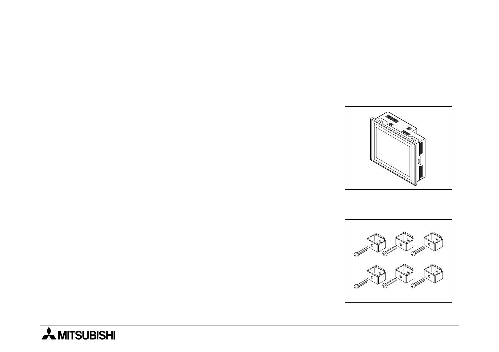
1) F940GOT (main body)
F940GOT-SWD-E: 5.7" STN type LCD (with eight colors)
F940GOT-LWD-E: 5.7" STN type LCD (with black and white)
2) Metal fixtures
Metal fixtures used to attach the GOT to a control panel
- Metal fixture 6 pieces
- Tightening bolt 6 pieces (M3 x 20)
1-8
Page 17

F940GOT-SWD-E/LWD-E INTRODUCTION 1.
3) Packing
Packing to prevent dusts and water
Used to attach the GOT to a control panel
1-9
Page 18

F940GOT-SWD-E/LWD-E INTRODUCTION 1.
Optional parts
4) Software to create user screens (3.5" FD)
FX-PCS-DU/WIN-E V2.10 or later
(in accordance with the Windows95)
SWoD5C-GOTRE-PACK
("o" indicates a numeric not less than 1.)
(in accordance with the Windows95 and the WindowsNT)
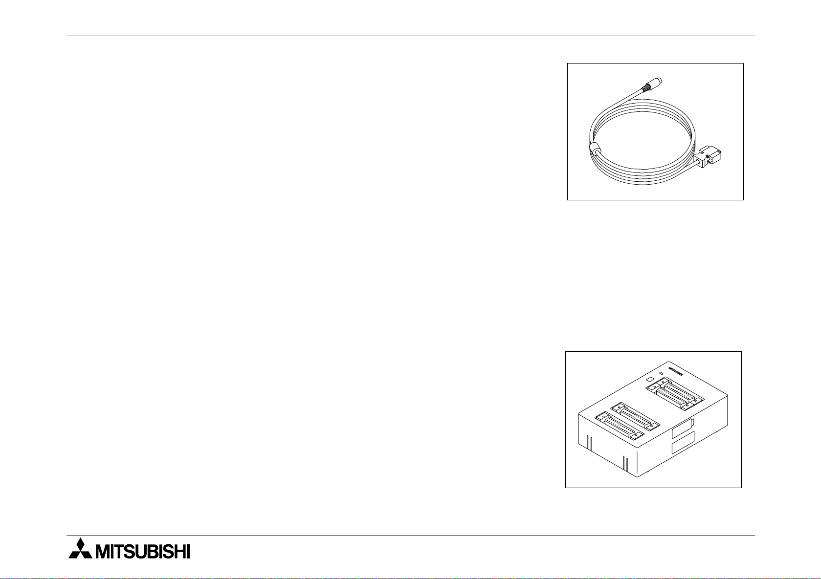
5) Connection cable FX-40DU-CAB (3 m, 9.84 ft)
Connection cable FX-40DU-CAB-10M (10 m, 32.81 ft)
Connection cable FX-50DU-CABL
(3m, 9.84 ft, with L-shape connector on the GOT side)
Each of them is an optional cab le to connect the GOT and the
FX/FX
2C
/A Series PLC.
1-10
Page 19
F940GOT-SWD-E/LWD-E INTRODUCTION 1.
6) Connection cable FX-50DU-CAB0 (3 m, 9.84 ft)
Connection cable FX-50DU-CAB0-1M (1 m, 3.28 ft)
Connection cable FX-50DU-CAB0-10M (10 m, 32.81 ft)
Connection cable FX-50DU-CAB0-20M (20 m, 65.62 ft)
Connection cable FX-50DU-CAB0-30M (30 m, 98.43 ft)
Connection cable FX-50DU-CAB0L
(3 m, 9.84 ft, with L-shape connector on the GOT side)
Each of them is an optional cable to connect the GOT and
the FX
0
/FX0S/FX0N/FX2N/FX
2NC
Series PLC.
By using either one, the GOT can be directly connected to
the PLC.
7) Two-port interface FX-2PIF
This is an optional interface to use the GOT and a periph-
eral unit to create sequence programs at the same time.
This is not required when the GOT is connected to a gener-
alpurpose personal computer or connected to a peripheral
unit via a computer link unit.
1-11
Page 20

F940GOT-SWD-E/LWD-E INTRODUCTION 1.
8) Battery PM-20BL (spare part)
This is used to bac k up the alarm history data, the real-time
clock, etc.
This is attached when the GOT is delivered.
9) EPROM memory to store the user screen data FX-EPROM4M
This is an optional EPR OM memory (M27C4002-**F (4 MB)
manuf actured b y SGS-THOMSON) to save the user screen
data.
The user screen data can be written using a general-purpose ROM writer connected to the screen creation software.
1-12
Page 21

F940GOT-SWD-E/LWD-E INTRODUCTION 1.
10) Data transfer adaptor F9GT-40UMB
This is an optional adaptor to connect the FX-EPROM-4M
9) and transfer the user scre en data to the flush memor y
inside the GOT.
When a same screen is to be transferred to two or more
GOT u nits, transfer can be performed quickly and easily
using this adaptor compared with the s creen creation s oftware.
11) Protection sheet F9GT-40PSC (5 sheets)
This optional sheet protects the display screen against
dirt.
Adhere it on the screen.
12) Replacement backlight F9GT-40LTS
This is a spare part of the display screen backlight.
The backlight is built in when the GOT is delivered.
1-13
Page 22
F940GOT-SWD-E/LWD-E INTRODUCTION 1.
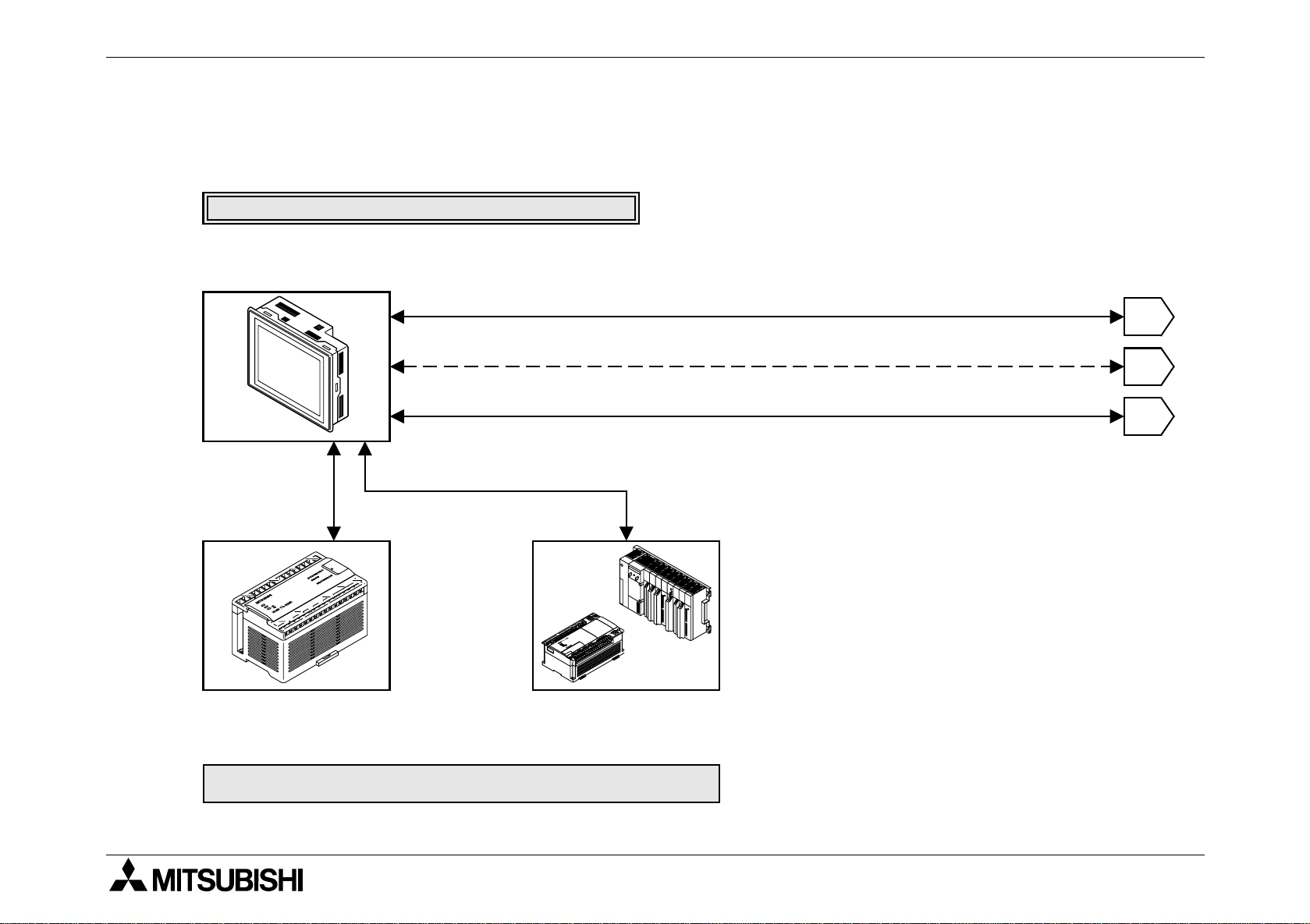
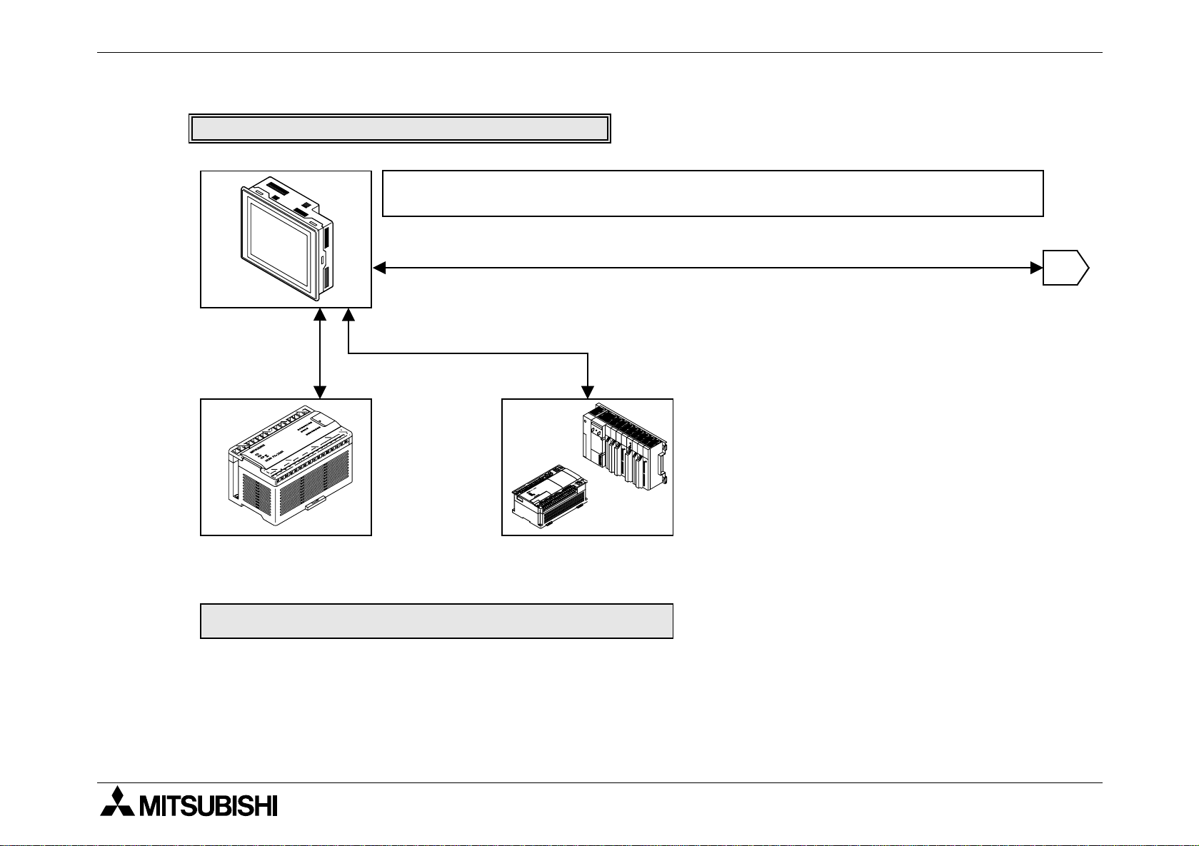
1.3 System configuration
The system configuration to use the GOT is described below.
When the GOT is directly connected to the PLC
F940GOT-SWD-E/LWD-E
Connection cable FX50DU-CAB0 for CPU
port connection*1
:When the GOT is connec ted via a computer link unit, refer to
Section 2.
Data transfer cable FX -232CAB-1 (when the RS -232C c onnector in the personal
computer is 9-pin t ype) or Dat a transfer cable FX-232CAB-2 (when the RS-232C
connector in the pers onal computer is half-pitch,14-pi n type)
Attach a ROM to the F9GT-40UMB, then connect it to a connec tor provided on the rear
face of the GOT.
Data transfer cable F2-232CA B-1
It cannot be used when a computer link (RS-232C communication) is used.
Connection cable FX-40DU-CAB *1
*1 Connection cables of different lengt h are av ai l abl e.
(Refer to the options in "1. 2 P roduct configuration".)
1
2
3
FX0/FX0S/FX0N/FX2N/
2NC
FX
Series
PC
FX/FX
A Series (except QnA)
Motion controller
Series
2C
1-14
Page 23
F940GOT-SWD-E/LWD-E INTRODUCTION 1.
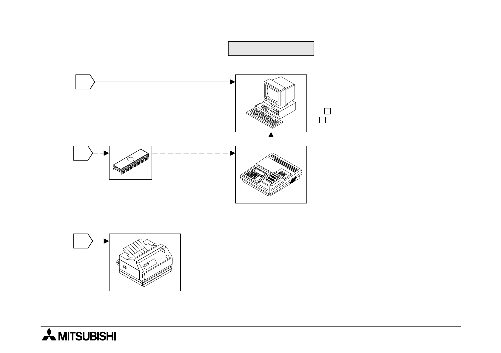
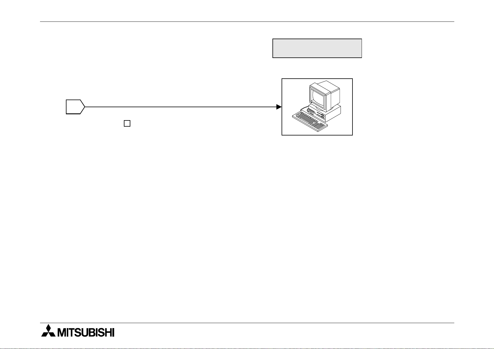
Peripheral units for GOT
General-purpose personal computer
(screen creation software)
1
Data transfer cable F2-232CA B -1
(when the RS-232C connector in the
personal computer is 25-pin type)
Connected to RS-232C connec tor in GOT
2
EPROM memory
FX-EPROM-4M
(User screen data can be written
using a general-purpose ROM writ er.)
3
Screen creation sof tware for DU FXPCS-DU/WIN-E (V2.10 or later)
Screen creation sof tware for A900GOT
SW D5C-GOTRE-PACK
(" " is a numeric not less than 1.)
ROM writer
General-purpose ROM writer
Printer
< Dedicated printers >
GT-10A
K6PR(-K), A7(N)PR
< General-purpose printers >
ESC/P
Printer equipped with RS-232C interface
(Prints out sampling data, alarm history and alarm mes sages.)
1-15
Page 24
F940GOT-SWD-E/LWD-E INTRODUCTION 1.
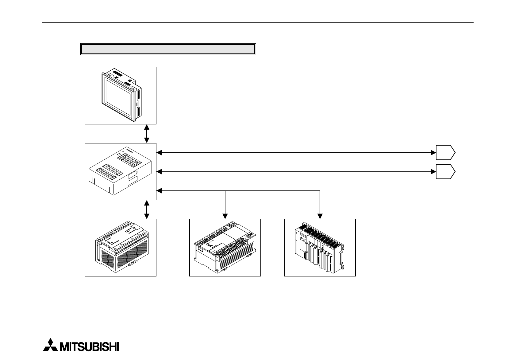
The figure below shows connection to peripheral units used to create sequence programs.
When built-in two-port interfa ce function is used
F940GOT-SWD-E/LWD-E
When the two-port interface f unction is used, the operation environment should be set.
(Refer to the description on "SERIAL PORT" on the SET-UP MODE screen.)
Data transfer cable FX -232CAB-1
Connection cable FX50DU-CAB0 for CPU
port connection*1
(when the RS-232C connector in the pers onal computer is 9-pin type)
Data transfer cable F2-232CA B-2
(when the RS-232C connector in the pers onal computer is half-pitch, 14-pin type)
Connected to RS-232C connector in GOT
Connection cable FX-40DU-CAB *1
*1 Connection cables of different lengt h are av ai l abl e.
(Refer to the options in "1. 2 P roduct configuration".)
1
FX0/FX0S/FX0N/FX2N/
2NC
Series
FX
FX/FX2C Series
A Series (except QnA)
Motion controller
PC
1-16
Page 25
F940GOT-SWD-E/LWD-E INTRODUCTION 1.
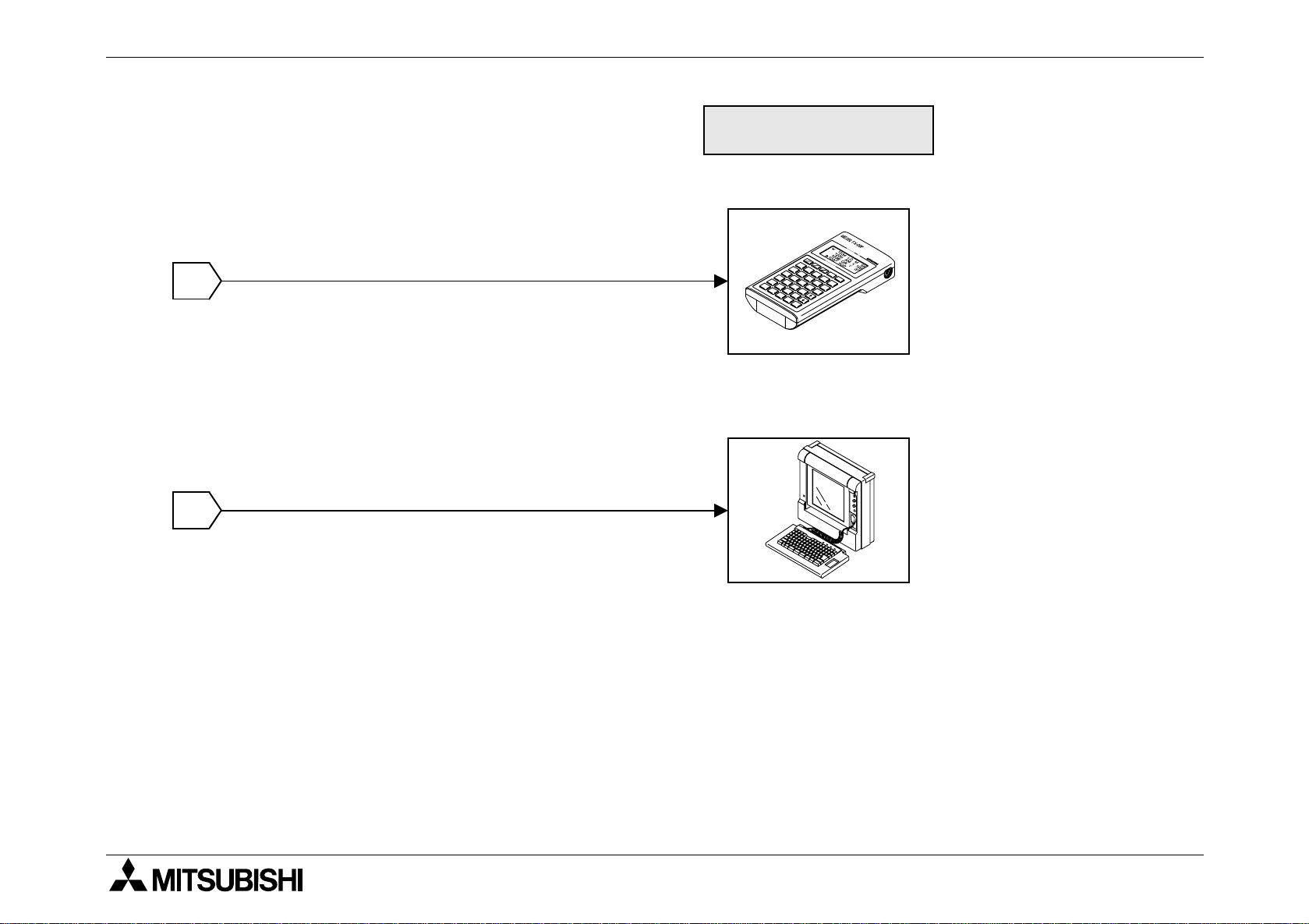
Peripheral unit to create
sequence programs
General-purpose
personal computer
* A general-purpose computer can be directly connected, and
both the GOT and the personal computer can be used at
the same time (without using the FX-2PIF).
1
When the two-port interface f unction is used using the sof tware
package SW D5C(F)-GPPW-E, make sure to use the
connection cabl e having the model name shown on the left to
connect a personal computer.
Note:
This two-port inte rface function is effective in CPU port connection ( via the RS-422). This
function is not a v ailab le in computer link connec tion (via the RS-422 or the RS-232C) and CPU
port connection (via the RS-232C).
And even in CPU po r t connect ion (via the RS-422 ), this funct ion is not available when two or
more GOT units are connected (Refer to Paragraph 2.7.).
1-17
Page 26
F940GOT-SWD-E/LWD-E INTRODUCTION 1.
When the two-port interface FX-2PIF is used
F940GOT-SWD-E/LWD-E
Two-port interface
FX-2PIF
Data transfer cable
FX-422CAB0
2NC
FX
Series
Connection cable FX-40DU-CAB/EN
Program cable FX-20P-CAB
Data transfer cable AC30R4
Data transfer cable FX-422CAB or
Data transfer cable FX-422CAB-150
FX/FX
2C
/ SeriesFX0/FX0S/FX0N/FX2N/
1
2
A Series (except QnA)
1-18
Page 27
F940GOT-SWD-E/LWD-E INTRODUCTION 1.
Peripheral unit to create
sequence programs
Handy programming
panel FX-10P -E/20P-E
1
(A Series cannot be used.)
A7PHP/A7HGP
A6GPP/A6PHP
The FX2N/FX
can be used in the
instruction/device
2
range of the F X Series.
2NC
Series
Note:
The two-port interface FX-2PIF is available in CPU por t connection (via the RS-422). This
interface is not available in computer link connection (via the RS-422 or the RS-232C) and
CPU port connection (via the RS-232C).
And even in CPU port connection (via the RS-422), this interface is not available when two or
more GOT units are connected (Refer to Paragraph 2.7.).
1-19
Page 28

F940GOT-SWD-E/LWD-E INTRODUCTION 1.
1-20
Page 29

F940GOT-SWD-E/LWD-E
Installation, Wiring and General Specifications 2.
2. Installation, Wiring and General Specifications
This section describes installation of the GOT and wiring of the power supply.
2.1 Installation of main body
Caution on installation
• Use the unit in the environment for the general specifications described in the manual.
Never use the unit in a place with dusts, soot, conductive dusts, corrosiv e gas or flam mable gas, place exposed to high temperature, condensation or wind and rain or a place
subject to vibrations or impacts.
If the unit is used in an unfa v or ab le place described above, electrical shoc k, fire, malfunction, damages of the unit or deterioration of the unit may be caused.
• Never drop cutting chips and wiring chips into the vent ila tion wind ow of the graphic oper-
ation terminal when you drill screw holes or perform the wiring work.
Fire, failure or malfunction may be caused.
• Connect a connection cable and mount an extension module securely to the specified
connectors respectively while the power is turned off.
Imperfect connection may cause malfunction.
2-1
Page 30
F940GOT-SWD-E/LWD-E Installation, Wiring and General Specifications 2.
153 (6.02 )
+1
- 0
mm
(inches)
121 (4.76 )
+1
-0
+0.04
- 0.00
+0.04
- 0.00
a)
b)
c)
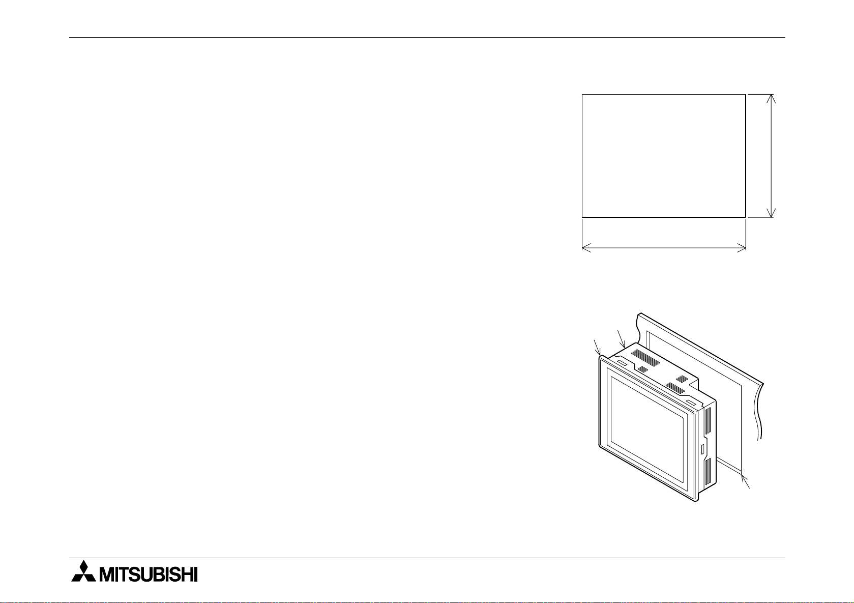
The GOT is to be embedded in a panel. Perform the installation procedure described below.
1) Machining the mounting panel face
On the panel face, drill a mounting hole of the dimensions
shown on the right.
* Make sure that the plate thic kness of the mounting pa nel
is 5 mm (0.2 inches) or less.
2) Inserting the GOT into the panel face
Attach a packing to the GOT. Insert the GOT from the fro nt
of the panel face.
a) GOT
b) Packing
c) Mounting hole
2-2
Page 31

F940GOT-SWD-E/LWD-E Installation, Wiring and General Specifications 2.
Enlarged view
a)
b)
a)
b)
-
+
24VDC
5 (0.20)
or less
57 (2.24)
152 (5.98)
120 (4.72)
mm
(inches)
3) Fixing the GOT
Hang the hook of each metal fixture (offered as accessory)
to a mounting hook hole in the GOT. Tighten a mounting
bolt (offered as accessory) securely in each position.
The GOT can be fixed in four positions at corners.
However, to prevent dusts and water, fix the GOT in six
positions.
a) Metal fixture
b) Tightening bolt
* Make sure that the tightening torque for each tightening
bolt is 0.3 to 0.5 N m.
4) Inside dimensions of the panel required for installation
When installing the GOT, make sure that the inside dimen-
sions shown on the right are assured in the panel.
a) PLC connection cable
b) Packing
2-3
Page 32

F940GOT-SWD-E/LWD-E Installation, Wiring and General Specifications 2.
2.2 Wiring of power supply
Cautions on Wiring
• Make sure to shut down the power supply outside the unit before starting installation or
wiring.If the power supply is not shut down outside, electrical shock or damages of the
unit may be caused.
CAUTION
• Connect the DC power cable to a dedicated terminal as described in this manual.
If the AC power supply is connected to a DC power terminal or an I/O terminal, the
graphic operation terminal may be burnt.
• Attach a fuse of 2A to the 24V DC po wer supply. Connect the + side and the - side of the
DC power supply correctly as described in this manual.
If the power supply is connected reversely, failures may be caused.
• Use wires of 1.25 mm
2
or more for a ground terminal in the graphic operation terminal.
When supplying the po wer from a prog ramm abl e controller, connect a ground terminal in
the graphic operation terminal to a ground terminal in the programmable controller and
perform Class 3 grounding. When supplying the power from the outside, connect a
ground terminal in the graphic operation terminal to a ground terminal in the connected
external power supply unit and perform Class 3 grounding.
Never perform common grounding with strong electrical systems.
2-4
Page 33

F940GOT-SWD-E/LWD-E Installation, Wiring and General Specifications 2.
The power is supplied to the GOT from a PLC or an external power supply unit.
• Connection examples
1) When the power is supplied from an FX Series PLC (Refer to "Cautions on connection" in
the next page.)
Connect the power terminal in the GOT to the 24V DC service power supply in the PLC
basic unit or PLC extension unit.
2A
Class 3
Class 3
grounding
grounding
24V 0V S/S RUN X0 X1 X2
PLC GOT
- +
DC
24V
2-5
Page 34

F940GOT-SWD-E/LWD-E Installation, Wiring and General Specifications 2.
2) When the power is supplied from an external power supply unit
Connect the power terminal provide d on the rear face of the GO T to the 24V DC terminal in
the external power supply unit.
Class 3
grounding
24V 0V S/S RUN X0 X1 X2
PLC GOT
Class 3
grounding
2A
- +
DC
24V
2-6
Page 35

F940GOT-SWD-E/LWD-E Installation, Wiring and General Specifications 2.
• Specifications of power supply unit
Specifications
Item
F940GOT-LWD F940GOT-SWD
Supply voltage 24V DC
+10%
-15%
Power ripple 200mV or less
Current consumption 390mA / 24V DC 410mA / 24V DC
Allowable instantaneous
power interruption duration
Operation shall be continued against instantaneous
power interruption for less than 5 ms.
2-7
Page 36

F940GOT-SWD-E/LWD-E Installation, Wiring and General Specifications 2.
Cautions on connection
• The current consumption of the GOT is as shown in the table above. When supplying the
power to the GOT from the 24V DC service po wer in the FX Series PLC basic unit or extension unit, take into account the total current supplied to proximity switches and extension
blocks. If the total current exceeds the capacity of the ser vice power, the GOT should
obtain the power from an exter nal power supply unit. In the case of the FX
0
/FX0S/FX
0N
Series PLC, an external power supply unit is required.
• Even if instantaneous power interruption for less than 5 ms occurs in the power supply unit,
the GOT continues its operation.
When power interruption for 5 ms or more or the voltage drop occurs, the GOT stops its
operation. However, when the power is recovered, the GOT automatically restarts operation. (The screen displayed after recover y is deter mined by the operation environment setting.)
• For wir ing of the power supply, use electric wires of 0.75 mm
2
or more so that voltage drop
does not occur. Use crimp-style terminals of M3 size, and tighten them securely with the
torque of 0.5 to 0.8 N m so that troubles will not occur.
2-8
Page 37

F940GOT-SWD-E/LWD-E Installation, Wiring and General Specifications 2.
POWER
162 (6.38)
130 (5.12)
a)
mm (inches)
2.3 Functions of operation keys and connectors
1) Front panel
a) Display unit
Allows graphic display of 320 × 240 dots.
Character string: 20 full-width characters × 15 lines
40 half-width characters × 15 lines
Alphabets, numerics, Katakana characters and Kanji
characters (JIS Level 1) can be displayed in the size of
1 to ×4 in each of the vertical and horizontal directions.
×
Alphabets, numerics and Katakana characters can be
displayed also in the size of ×1/4.
2-9
Page 38

F940GOT-SWD-E/LWD-E Installation, Wiring and General Specifications 2.
-
+
24VDC
152 (5.98)
b)c)
a)
mm (inches)
2) Rear panel
a) Power terminal
Supplies the power to the GOT, and allows grounding.
b) Battery PM-20BL
Backs up the sampling data, the alarm history and the
current time.
The screen data is stored in the built-in flush memory,
and does not require the battery.
c) Extension interface
Connects an optional e x tension equipment.
Connects the data transfer adopter F9GT-40UMB to
transfer the screen data stored in the EPROM.
2-10
Page 39

F940GOT-SWD-E/LWD-E Installation, Wiring and General Specifications 2.
RS232C
RS422
a)
b)
3) Connectors provided on the side
Used when a printer is connected or when a PLC is con-
nected via a computer link unit.
a) Connector for personal computer (RS-232C connector):
D-sub 9-pin, male
b) Connects a personal computer to transfer to the PLC
the screen data created by the screen creation software
and sequence programs using the two-port interface
function.
2-11
Page 40

F940GOT-SWD-E/LWD-E Installation, Wiring and General Specifications 2.
2.4 Outside dimensions
57 (2.24)
5
(0.20)
RS232C RS422
120 (4.72)
152 (5.98)
162 (6.38)
POWER
130 (5.12)
Outside painting color: Munsell 0.08GY 7.64/0.81
Mass: Approximately 1.0 kg including metal fixtures (0.1 kg)
Panel cut dimensions: 153 × 121 (6.02 × 4.76 )
-0
+1
+1
-0
+0.04
-0.00
+0.04
-0.00
Unit: mm (inches)
2-12
Page 41

F940GOT-SWD-E/LWD-E Installation, Wiring and General Specifications 2.
2.5 General specificationsl
Ambient temperature
Ambient humidity
Vibration resistance
Impact resistance
Noise resistance
During operation: 0 to +50°C (0 to +40°C when extension interface is used)
During storage: -20 to +60°C
During operation: 35 to 85%RH (Condensation shall not be allowed.)
Frequency Acceleration Amplitude
When inter-
In accor-
mittent
10-57Hz - 0.075mm
10 times in
each of X,
dance with
JIS B3501
vibrations
are applied
57-150Hz
9.8m/s
2
-
Y and Z
directions
and IEC
1131-2
When continuous
vibrations
10-57Hz - 0.035mm
57-150Hz 4.9m/s
2
-
(for 80
minutes)
are applied
In accordance with JIS B3501 and IEC 1131-2 (147 m/s
2
, three times in
each of X, Y and Z directions)
By noise simulator whose noise voltage is 1,000 Vp-p, noise width is 1µs and
cycle is 30 to 100 Hz
Withstand voltage
Insulation resistance
Grounding
Operating atmosphere
Protection structure
500V AC for 1 minute
500V DC, 5MΩ or more by megger
Class 3 grounding
Corrosive gas and much dusts shall not be detected.
IP65F
Between all power terminals as a whole
and ground terminal
2-13
Page 42

F940GOT-SWD-E/LWD-E Installation, Wiring and General Specifications 2.
24V DC +10%, -15%
Supply voltage
Current consumption: 390 mA/24V DC (F940GOT-LWD-E)
410 mA/24V DC (F940GOT-SWD-E)
Display element
Screen
Service life
Backlight
Key
Interface
STN type full-dot matrix LCD, m onochrome (F940GOT-LWD-E) or color
(F940GOT-SWD-E)
LCD of 320 x 240 dots, 20 full-width characters × 15 lines,
Effective display size: 115 × 86 mm (5.7 inches)
LC: Approximately 50,000 hours
Cold cathode tube (Service life: 25,000 times or more)
50 touch keys maximum/screen, 20 × 12 matrix
One channel in conformance to RS-422 for communication with PLC
One channel in conformance to RS-232C for transfer of screen data
Extension interface for connection of optional extension unit
2-14
Page 43

F940GOT-SWD-E/LWD-E Installation, Wiring and General Specifications 2.
2.6 Connection to personal computer
Use the following cable to connect a personal computer.
b)
a)
c)
a) F940GOT
b) Personal computer
c) FX-232CAB-1, FX-232CAB-2 or F2-232CAB-1
2-15
Page 44

F940GOT-SWD-E/LWD-E Installation, Wiring and General Specifications 2.
Pin assignment and connection diagram of transfer cables
- Transfer cable FX-232CAB-1
D-sub
(female)
9-pin
5
4
3
2
1
9
8
7
6
Personal
computer
side
- Transfer cable FX-232CAB-2
7
Half
pitch
9-pin
1
14
Personal
computer
side
8
2
3
6
8
5
4
1
2
4
9
11
14
12
13
2
3
6
8
5
4
3
4
2
6
8
5
GOT side
GOT side
5
4
3
2
1
5
4
3
2
1
9
8
7
6
9
8
7
6
D-sub
(female)
9-pin
D-sub
(female)
9-pin
2-16
Page 45

F940GOT-SWD-E/LWD-E Installation, Wiring and General Specifications 2.
- Transfer cable F2-232CAB-1
D-sub
(male)
25-pin
13
12
11
10
9
8
7
6
5
4
3
2
1
25
24
23
22
21
20
19
18
17
16
15
14
Personal
computer
side
1
2
3
5
6
7
20
2
3
GOT
8
side
4
5
6
5
4
3
2
1
9
8
7
6
D-sub
(female)
9-pin
2-17
Page 46

F940GOT-SWD-E/LWD-E Installation, Wiring and General Specifications 2.
OUT
I N
OUT
CPU¥E
PROG¥E
5
4
3
2
1
0
7
6
5
4
3
2
1
0
X7
X6
X5
X4
X3
X2
X1
X0
COM
N
L
Y5
Y4
Y3
Y2
COM2
Y1
COM1
Y0
COM0
COM
24+
RUN
POWER
c)
f)
a)
2.7 CPU port connection
Use either of the following cables to connect the PLC directly.
2C
1) When connecting the FX/FX
/A Series
2) When connecting the FX
0
/FX0S/FX0N/FX2N/FX
2NC
Series
1) 2)
a)
b)
d)
e), g)
* When the screen mode is selected while a cable is not connected, a communication
error occurs.
2-18
Page 47

F940GOT-SWD-E/LWD-E Installation, Wiring and General Specifications 2.
a) F940GOT
b) FX-40DU-CAB, FX-40DU-CAB-10M or FX-50DU-CABL
c) FX-50DU-CAB0, FX-50DU-CAB0-1M, FX-50DU-CAB0-10M,
FX-50DU-CAB0-20M, FX-50DU-CAB0-30M or FX-50DU-CAB0L
2C
d) FX/FX
Series PLC
e) A Series PLC
AnN, AnA, AnS, AnSJ, AnSH, A1SJH, A2C, A2CJ, A0J2H, AnU, AnUS, A2USH or A1FX
CPU
f) FX
0
/FX0S/FX0N/FX2N/FX
2NC
Series PLC
g) Motion controller
A171SCPU-S3, A171SHCPU, A172SHCPU or A272UHCPU
2-19
Page 48

F940GOT-SWD-E/LWD-E Installation, Wiring and General Specifications 2.
Pin assignment and connection diagram of connection cables (The connection cables are
offered as options.)
- Connection cable FX-40DU-CAB (L, -10M) or FX-50DU-CABL
D-sub
(male)
25-pin
13
12
11
10
9
8
7
6
5
4
3
2
1
25
24
23
22
21
20
19
18
17
16
15
14
PLC
side
2
3
4
5
7
15
16
17
18
8
21
1
2
3
4
5
6
7
8
9
GOT
side
5
4
3
2
1
- Connection cable FX-50DU-CAB0 (L, -1M, -10M, -20M, -30M)
MINI-DIN
(male)
8-pin
3
4
6
1
7
2
8
5
PLC
side
2
7
6
3
1
4
5
1
2
4
5
6
7
9
GOT
side
5
4
3
2
1
9
8
7
6
9
8
7
6
D-sub
(male)
25-pin
D-sub
(male)
9-pin
2-20
Page 49

F940GOT-SWD-E/LWD-E Installation, Wiring and General Specifications 2.
• When the CPU in the FX/A Series PLC is directly connected, up to four GOT units can be
connected to one PLC (1-to-N connection).
As the connection type, select "CPU PORT (RS232C)" or "CPU PORT (RS422)" in "CONNECTION" on the PLC TYPE screen.
System configuration
Side of GOTFX/A Series
1st unit 2nd unit 3rd unit 4th unit
RS-422 communication
Maximum extension
distance: 30 m (98.4 ft)
RS-232C
communication
15 m (49.2 ft)
RS-422C
communication
30 m (98.4 ft)
RS-232C
communication
15 m (49.2ft)
Note:
While the GO T display is used, peripheral units of the GOT and peripheral units used to cre-
ate sequence programs cannot be used except when the following system configuration is
realized using the FX
2N
-422-BD in the FX2N Series. Cables to connect such peripheral
units should be disconnected while the GOT display is used.
2-21
Page 50

F940GOT-SWD-E/LWD-E Installation, Wiring and General Specifications 2.
Connection diagram
1
2
3
4
5
6
7
8
9
1
2
3
4
5
6
7
8
9
Connection cable examples:
1st GOT: FX-50DU-CAB0
(equivalent to connection cable for PLC)
2nd GOT: FX-232CAB-1
3rd GOT: Cable created by user
(Refer to the connection diagram.)
4th GOT: FX-232CAB-1
Communication speed: The communication speed with the PLC becomes slower as the
number of connected GOT units becomes larger.
When the speed in the case one GOT unit is connected is regarded as "1",
Speed in 1st unit x 2 = Speed in 2nd unit (1/2 of speed in 1st unit)
Speed in 2nd unit x 2 = Speed in 3rd unit (1/4 of speed in 1st unit)
Speed in 3rd unit x 2 = Speed in 4th unit (1/8 of speed in 1st unit)
• In this case, peripheral units used to create sequence programs can be connected using
programming connectors in the FX
2N
unit.
2-22
Page 51

F940GOT-SWD-E/LWD-E Installation, Wiring and General Specifications 2.
• In the case of the FX2N Series, communication can be performed by CPU port connection
2N
(RS-232C communication) using the FX
-232-BD.
In this case also, In the case of the FX
port connection (RS-232C communication) using the FX
2N
Series, communication can be performed by CPU
2N
-232-BD.
In this case also, up to four GOT units can be connected to one PLC (1-to-N connection).
Up to four GOT units can be connected to one PLC (1-to-N connection).
To connect peripheral units used to create sequence programs, use programming connectors in the FX
2N
main unit.
System configuration
Series
FX
2N
RS-232C communication
Maximum extension
distance: 15 m (49.2 ft)
FX
-232-BD
2N
RS-422
communication
30m (98.4ft)
RS-232
communication
15m (49.2 ft)
RS-422
communication
30m (98.4 ft)
2-23
Page 52

F940GOT-SWD-E/LWD-E Installation, Wiring and General Specifications 2.
Connection cable examples:
1st GOT: FX-232CAB-1
2nd GOT: Cable created by user
(Refer to the connection diagram.)
3rd GOT: FX-232CAB-1
4th GOT: Cable created by user
(Refer to the connection diagram.)
Connection diagram
1
2
3
4
5
6
7
8
9
1
2
3
4
5
6
7
8
9
Communication speed: The communication speed with the PLC becomes slower as the
number of connected GOT units becomes larger.
When the speed in the case one GOT unit is connected is regarded as "1",
Speed in 1st unit x 2 = Speed in 2nd unit (1/2 of speed in 1st unit)
Speed in 2nd unit x 2 = Speed in 3rd unit (1/4 of speed in 1st unit)
Speed in 3rd unit x 2 = Speed in 4th unit (1/8 of speed in 1st unit)
2-24
Page 53

F940GOT-SWD-E/LWD-E Installation, Wiring and General Specifications 2.
<Cautions on connection of two or more GOT units>
When two or more GOT units are connect ed to the FX/ A/QnA Ser ies PLC, communication is
performed in the location sequence from the GOT unit nearest to the CPU (th at is, in the
sequence of the 1st, 2nd, 3rd and 4th GOT units). Accordingly, when turning on the power of
the GOT units for the first time, turn on the power from the one nearest to the CPU.
If the power cannot be turned on in the GOT units from the one nearest to the CPU, set the
GOT units (in "SET-UP MODE") or the screen creation software so that communication is performed while the title screen display time is different by 2 to 3 seconds in each GOT unit.
Setting example: The title screen display time is different by 2 seconds in each GOT unit, and
communication is started from the GOT unit nearest to the CPU.
FX/A/QnA Title screen display time (initial value: 4 sec)
1st GOT: 4 sec 2nd COT: 6 sec 3rd COT: 8 sec 4th COT: 10 sec
* Perform the same setting without regard to the conn ecti on type (RS-232C or RS-4 22) of two
or more GOT units.
2-25
Page 54

F940GOT-SWD-E/LWD-E Installation, Wiring and General Specifications 2.
2.8 Computer link port connection (MELSEC A Series)
The GOT can be connected to the MELSEC A Series via a computer link unit as shown below.
• Applicable PLC units and computer link units
< A Series >
AJ71UC24 A1SJ71UC24-R2/R4/PRF A1SJ71C24-R2/R4/PRF
A1SCPU24-R2 A2CCPUC24 (PRF)
For the communication setting f or the computer link unit, re f er to the F940GOT Operation Manual offered separately.
• System configuration
Programming
connector
is not used.
RS232C
RS232C
RS422
RS422
For the connection diagram, refer to the next page.
To computer link unit
2-26
Page 55

F940GOT-SWD-E/LWD-E Installation, Wiring and General Specifications 2.
• Connect the GOT to the computer link unit (PLC) as shown below.
< For RS-422 communication >
1
6
GOT
2
side
7
5
5
4
3
2
1
9
D-sub
8
(male)
7
9-pin
6
Terminal
block
Computer link
unit side
(PLC side)
RDA
RDB
SDA
SDB
SG
< For RS-232C communication > The connection cable F2-232CAB is also available.
D-sub
25-pin
13
12
11
10
9
8
7
6
5
4
3
2
1
25
24
23
22
21
Computer link
20
19
18
17
16
15
14
unit side
(PLC side)
FG
SD
RD
RS
CS
DSR
SG
CD
DTR
1
2
3
4
5
6
7
8
20
1
2
3
7
GOT
8
side
6
5
4
5
4
3
2
1
9
8
7
6
D-sub
(female)
9-pin
2-27
Page 56

F940GOT-SWD-E/LWD-E Installation, Wiring and General Specifications 2.
< For RS-232C communication >
D-sub
9-pin
CD
1
RD
2
5
4
3
2
1
9
Computer link
8
7
6
unit side
(PLC side)
SD
DTR
SG
DSR
RS
CS
3
4
5
6
7
8
1
2
3
GOT
4
5
6
7
8
side
5
4
3
2
1
9
8
7
6
D-sub
(female)
9-pin
2-28
Page 57

F940GOT-SWD-E/LWD-E Installation, Wiring and General Specifications 2.
2.9 Connection to SYSMAC C Series
The GO T can be connecte d to the SYSMAC C Series manufactured b y OMR O N via a host link
unit as shown below.
• Applicable PLC units and host link units
< SYSMAC C Series >
A host link unit or a CPU equipped with an interface for host link is required.
For the setting of the host link unit, refer to the F940GOT Operation Manual offered
separately.
• System configuration
To host link unit
RS232C
RS232C RS422
RS422
2-29
Page 58

F940GOT-SWD-E/LWD-E Installation, Wiring and General Specifications 2.
• Connect the GOT to the host link unit (SYSMAC C Series) as shown below.
For connection of a model not shown in the examples below, refer to the manual of the C
Series link unit.
< For RS-422 communication > Example of connection to C200H-LK202-V1
1
6
GOT
2
7
5
side
5
4
3
2
1
9
8
7
6
D-sub
9-pin
1
5
4
3
2
1
9
8
7
6
Host link
unit side
(C200H side)
RDB
RDA
SDB
SDA
SG
6
5
9
3
< For RS-232C communication > Example of connection to C200H-LK201-V1
D-sub
25-pin
13
12
11
10
9
8
7
6
5
4
3
2
1
25
24
23
22
21
20
19
18
17
16
15
14
Host link
unit side
(C200H side)
FG
SD
RD
RS
CS
SG
1
2
3
4
5
7
1
2
GOT
3
7
side
8
5
5
4
3
2
1
9
8
7
6
D-sub
(male)
9-pin
D-sub
(female)
9-pin
2-30
Page 59

F940GOT-SWD-E/LWD-E Installation, Wiring and General Specifications 2.
< For RS-232C communication >
Example of connection to CQM1 (in which RS-232C port is built in)
D-sub
9-pin
FG
1
5
4
3
2
1
9
8
7
6
COM1
side
SD
RD
RS
CS
SG
2
3
4
5
9
1
2
GOT
3
7
side
8
5
5
4
3
2
1
9
8
7
6
D-sub
(female)
9-pin
2-31
Page 60

F940GOT-SWD-E/LWD-E Installation, Wiring and General Specifications 2.
2.10 Connection to FLEX-PC N Series
The GOT can be connected to the FLEX-PC N Series manufactured by FUJI Electric via a link
unit shown below.
• Connection type
Link port connection (RS-422)
Link port connection (RS-232C)
CPU port connect ion (RS-232C)
Select the connection type using
the operation envir onment setting
described in the nex t section or
the screen creation software.
• Applicable PLC units and link units
< FLEX-PC N Series >
A link unit (general-purpose RS-232C/RS485 interface module) is required to be connected. Or a CPU in which an RS-232C interface is built in is required.
• System configuration
RS232C
RS232C
RS422
RS422
To link unit or built-in RS-232C interface
2-32
Page 61

F940GOT-SWD-E/LWD-E Installation, Wiring and General Specifications 2.
• Link unit
- NB Series
NB-RS1-AC, NB-RS1-DC
-NJ Series
NJ-RS2, NJ-RS4
- NS Series
NS-RS1
- CPU in which RS-232C interface is built in NJ-CPU-B16
• Connection diagram
Connect the GOT and the link unit (PLC) as shown below.
< For link port connection (RS-422) >
RDA
Terminal
block
Link unit side
(PLC side)
RDB
SDA
SDB
SG
1
6
GOT
2
side
7
5
5
4
3
2
1
9
D-sub
8
(male)
7
9-pin
6
2-33
Page 62

F940GOT-SWD-E/LWD-E Installation, Wiring and General Specifications 2.
< For link port connection (RS-232C) >
D-sub
25-pin
13
12
11
10
9
8
7
6
5
4
3
2
1
25
24
23
22
21
Link unit side
20
19
18
17
16
15
14
(PLC side)
FG
SD
RD
RS
CS
DSR
SG
DTR
1
2
3
4
5
6
7
20
< For connection of built-in RS-232C interface >
D-sub
15-pin
8
7
6
5
4
3
2
1
15
14
13
12
11
10
9
PLC side
RD
SD
RS
CS
SG
2
3
4
5
7
1
2
3
7
8
6
5
4
2
3
7
8
5
GOT
side
GOT
side
5
4
3
2
1
5
4
3
2
1
9
8
7
6
9
8
7
6
D-sub
(female)
9-pin
D-sub
(female)
9-pin
2-34
Page 63

F940GOT-SWD-E/LWD-E Installation, Wiring and General Specifications 2.
2.11 Connection by general-purpose communication
The GOT can be connected to a general controller such as micro computer board.
(The connected controller is hereafter referred to as "host (unit)".)
• Outline
In genera-purpose communication, the host unit is connected to the GOT via the RS-232C
and functions as the parent station in communication. Inside the GOT, there is a data area
to hold word data and bit data. The host unit can read and write the data area using communication commands.
The contents of display and control in the GOT are determined by the screen data created
using the screen creatio n softw are in the pers onal compu ter. The screen data specifies the
lay out of objects dis pla yed on the screen, and sp ecifies actions to be perf ormed by pressin g
of touch keys.
The GOT is equipped with the function to display the word data in the form of numbers and
bar graphs, the function to access the data for changing the status of the bit data using
switches, etc.
The target of access is the data area inside the GOT. The data location to be accessed is
specified by the screen data.
2-35
Page 64

F940GOT-SWD-E/LWD-E Installation, Wiring and General Specifications 2.
Accordingly, to display the data stored in the host unit on the screen, the host unit should
transfer the data to the data area inside the GOT using write commands. The transfer destination is a location specified by the screen data. The data change result by manipulation
of ke ys can be tr a nsferred from the data area inside the GOT to the host unit if the host unit
gives read commands. In general-purpose communication, interrupt codes can be sent as
change triggers.
GOT
Screen data
Display/Input Internal data
Host unit
(micro computer board, etc.)
RS232C
2-36
Page 65

F940GOT-SWD-E/LWD-E Installation, Wiring and General Specifications 2.
• Connection diagram
Connect the GOT and the host unit as shown below.
FG
SD
RD
Host side
SG
1
2
3
GOT
7
8
side
6
4
5
5
4
3
2
1
9
D-sub
8
(male)
7
9-pin
6
* The control lines RTS, CTS, DTR and DSR are not used.
2-37
Page 66

F940GOT-SWD-E/LWD-E Installation, Wiring and General Specifications 2.
• Communication setting
The setting related to communication can be performed using the screen creation software
or the GOT main body.
To use general-purpose communication,
- Screen creation software: Set the connected personal computer to "General-Purpose
Communication".
- GOT main body: Select "SET-UP MODE", "PLC SYSTEM" and "GENERAL-PURPOSE
COMMUNICATION" in this order.
To set the baud rate, the data length, the stop bit length and the parity,
- Screen creation software: Sel ect "Others ", " S yst em Settin gs" an d "DU Serial Printer Set-
tings"
- GOT main body: Select "SET-UP MODE" and "SERIAL PORT (RS-232C)" in this order.
Set each parameter to an either value shown below.
Baud rate
Data length
Stop bit length
Parity
19,200 / 9,600 / 4,800 / 2,400 / 1,200 / 600 or 300 bps
8 or 7 bits
1 or 2 bits
Even, odd or none
2-38
Page 67

F940GOT-SWD-E/LWD-E
3. Startup
This section describes the startup procedure from turning on of the power of the GOT to selection of the mode.
This section describes also the environment setting important to use of the GO T. Make sure to
read this section carefully.
Startup 3.
3-1
Page 68

F940GOT-SWD-E/LWD-E Startup 3.
3.1 Startup procedure
This paragraph describes the star tup procedure from tur ning on of the power of the GOT to
selection of the mode.
Perform wiring of the
power supply unit of t he GOT .
Connect the PLC.
Turn on the
power without
pressing the
touch key.
The OPENING SCREEN is displayed.
The SET-UP MODE screen
is displayed.
Turn on the
power while
pressing the
touch key.
•Perform wiring of the power supply unit of the GOT.
(Refer to Section 2.)
•Connect the GOT and the PLC with an optional connection
cable.
•Turn on the power of the GOT. When the power is turned on
while the upper l eft cor ner (which fun ctions as a touch key)
of the screen of th e GOT is pressed and he ld for 1 second or
more, the SET-UP MODE screen is displayed.
(Refer to "3.2 Operation environment setting".)
•The OPENING SCREEN screen indicating the model name,
etc. is displayed for the period set in "OPENING SCREEN"
on the SET-UP MODE screen.
•On the SET-UP MODE screen, set the used mode, the connected PLC name, etc.
The operation environment can be set on the OTHER
1
MODE screen.
3-2
Page 69

F940GOT-SWD-E/LWD-E Startup 3.
1
A user screen is displayed.
When there is no screen data
The SELECT MODE
screen is displayed.
The selected mode
screen is displayed.
•A user screen is displayed. If any user screen has not been
created, the SELECT MODE screen is displayed as follows.
•The SELECT MODE screen is displ ayed. Each menu item on
2
the screen functions as a touch key. When a desired one is
pressed, the corresponding mode is selected.
* This SELECT MODE screen can be called also by press-
ing a corner of the screen set in "MAIN MENU CALL
KEY" on the SET-UP MODE screen.
•The selected mode screen is displayed.
2
The screen mode is
selected.
•If the menu call key is not set in "MAIN M ENU CAL L KEY " on
the SET-UP MODE screen, the user screen mode is
selected.
3-3
Page 70

F940GOT-SWD-E/LWD-E Startup 3.
[ SELECT MODE screen ]
[ SELECT MODE ]
USER SCREEN MODE
HPP MODE
SAMPLING MODE
ALARM MODE
TEST MODE
OTHER M O DE
END
3-4
Page 71

F940GOT-SWD-E/LWD-E Startup 3.
3.2 Operation environment setting
The operation environment setting function performs initial setting important to operation of the
GO T. The SET-UP MODE screen can be displa yed by turning on the power while pres sing and
holding the upper left corner of the screen in accordance with "3.1 Startup procedure" or by
selecting "SET-UP MODE" on the OTHER MODE screen.
If an entry code has been registered using the secur ity function (described in the F940GOT
Operation Manual offered separately), however, the operation environment can be set only
when an entry code input by the user is equivalent to the registered entry code.
Turn on the power while pressing and
holding the upper left c orner of the screen.
Set the system language (Refer to p. 44.).
Press the END key.
The SET-UP MODE screen is displayed.
a)
b)
c)
d)
e)
f)
g)
h)
i )
j )
[ SET-UP MODE screen ]
[ SET-UP MODE ]
LANGUAGE
PLC TYPE
SERIAL PORT
OPENING SCREEN
MAIN MENU CALL KEY
SET CLOCK
SET BACKLIGHT
BUZZER
LCD CONTRAST
CLEAR USER DATA
END
k)
l )
l )
3-5
Page 72

F940GOT-SWD-E/LWD-E Startup 3.
The areas enclosed with broken lines function as touch keys.
(Broken lines are not actually displayed on the screen.)
a) LANGUAGE
Allows to set the language displayed on the system screens such as Japanese and
English.
b) PLC TYPE
Allows to set the connected PLC type.
c) SERIAL PORT
To be selected when a pr inter is connected to the GOT or when communication is performed between the GOT and a micro computer board.
d) OPENING SCREEN
Allows to set the duration in which the OPENING SCREEN screen is displayed immediately after the power is turned on.
e) MAIN MENU CALL KEY
Allows to set the position of the touch key which calls the SELECT MODE screen from
the screen mode (in which a user screen is displayed).
f) SET CLOCK
Allows to set the time used in the time switch and the time display.
g) SET BACKLIGHT
Allows to set the time at which the backlight becomes extinguished.
3-6
Page 73

F940GOT-SWD-E/LWD-E Startup 3.
h) BUZZER
Allows to set the buzzer sound issued when a key is pressed.
i) LCD CONTRAST
Allows to set the LCD brightness.
j) CLEAR USER DATA
Deletes the user screen data.
k) END
Exits the SET-UP MODE screen.
l) Cursors
Change over the menu item on the SET-UP MODE screen.
3-7
Page 74

F940GOT-SWD-E/LWD-E Startup 3.
Each setting screen is displayed as shown below. On each screen, when the END key at the
upper righ t corne r is pressed after se tting is completed, the SET-UP MODE s creen is displayed.
[ PLC TYPE screen ]
[ PLC TYPE ]
SYSTEM LANGUAGE:
ENGLISH
CHARACTER
SET:
ENGLISH
END
a)
b)
• Set the language used on the system screens and the
user screens.
a) SYSTEM LANGUAGE
Allows to set the language displayed on the system
screens and in error messages.
JAPANESE and ENGLISH are available.
b) CHARACTER SET
Allows to set the language displayed on the user
screens. JAPANESE, CHINESE and KOREAN are
available. Only one language can be selected at a
time.
(CHINESE and KOREAN will be available in a few
days.)
3-8
Page 75

F940GOT-SWD-E/LWD-E Startup 3.
[ PLC TYPE screen ]
[ PLC TYPE ]
PLC TYPE:
CONNECTION:
STATION #:
FX SERIES
CPU PORT
* *
END
a)
b)
c)
• Select the connected PLC ty pe .
• The areas on the screen
enclosed with solid li nes function as touch keys. Every time
a touch key is pressed, the displayed contents a re changed
over.
a) PLC TYPE
Allows to select either one among FX SERIES, A
SERIES, C SERIES (manufactured by OMRON), N
SERIES (manufactured by FUJI Electric) and UNIVERSAL (general-purpose communication).
b) CONNECTION
Allows to set the connection method of the PLC
selected in 1] above.
- CPU PORT: The GOT is connected directly to the
program connector in the PLC.
The FX Series and the A Series are available.
- LINK PORT (RS422): The GOT performs communication in accordance with the RS-422 v ia a link unit.
The A Series, the C Series and the N Series are
available.
- LINK PORT (RS232C): The GOT perf orms communication with the DU in accordance with the RS232C via a link unit.
The A Series, the C Series and the N Series are
available.
3-9
Page 76

F940GOT-SWD-E/LWD-E Startup 3.
c) STATION #
Allows to set the station No. of the link unit connected
to the GO T when "LINK PORT" is selected in 2] abov e .
3-10
Page 77

F940GOT-SWD-E/LWD-E Startup 3.
[ SERIAL PORT]
[ SERIAL PORT]
SPEED
DATA BIT
STOP BIT
PARITY
HANDSHAKING
PRINTAER
9600 bps
:
7 bit
:
1 bit
:
Even
:
XON/XOFF
:
NOT USED
:
END
•Set the serial communication parameters for the printer
used to print out alarm messages and sampling data.
•Make sure to set "PRINTER" to "USE" when a printer is
connected.
When it is set to "USE", the two-port interface
function is not available.
•The areas enclosed with broken lines function as touch
keys.
Every time a touch key is pressed, the displayed contents are changed over.
•When "LINK PORT (RS232C)" is selected on the PLC
TYPE screen, any printer cannot be connected.
3-11
Page 78

F940GOT-SWD-E/LWD-E Startup 3.
[ OPENNING SCREEN ]
[ OPENNING SCREEN ]
DISPRAY TIME 20 SEC.
5 6 7 8 9 CLR
0 1 2 3 4 ENT
END
•Set the duration in the unit of second in which the
OPENING SCREEN screen indicating the model
name, the version, etc. is displayed when the power is
turned on.
•When the touch key "DISPLAY TIME" is pressed, the
time can be set using the ten-key pad displayed at the
bottom of the screen.
•Enter the desired display time using the ten-key pad displa y ed at the botto m of the scre en, then p ress the ENT
key to register the input time.
* When "DISPLAY TIME" is set to "0", the OPENING
SCREEN screen indicating only the version is displayed for 4 seconds.
It is recommended to set 1 second or more for the
FX Series and 4 seconds or more for the A Series.
3-12
Page 79

F940GOT-SWD-E/LWD-E Startup 3.
[ MENU CALL ]
[ MENU CALL KEY screen ]
SELECT CALL KEY LOCATION
END
•Set the menu call key which changes over the screen
mode (in which a user screen is displayed) to the
SELECT MODE screen.
The menu call key is mesh type, and 2 x 2 in size.
• One or two corners can be selected among the
four corners of the screen.
• When the menu call key is not set, only the screen
mode is available. Any other mode is not available.
• If another touch key is assigned to the corners to
which the menu call key has been assigned, the menu
call function is disabled.
3-13
Page 80

F940GOT-SWD-E/LWD-E Startup 3.
[ SET CLOCK ]
[ SET CLOCK ]
DATE 1 / 3 / 1999
TIME 10: 10: 10
5 6 7 8 9 CLR
0 1 2 3 4 ENT
END
• Set the time used in the time switch, the sampling
mode and the alarm mode.
•When "DATE" or "TIME" is selected, date or time can be
entered using the ten-key pad displayed at the bottom
of the screen. Enter the desired da te or time, and
press the ENT key to register it.
3-14
Page 81

F940GOT-SWD-E/LWD-E Startup 3.
[ SET BACKLIGHT ]
[ SET BACKLIGHT ]
OFF TIME 10 MIN.
5 6 7 8 9 CLR
0 1 2 3 4 ENT
END
•Set the time at which the backlight of the display screen
becomes extinguished. When a touch key is not
pressed or the user screen is not changed over within
the specified OFF time, the backlight becomes extinguished.
•When "OFF TIME" is pressed, the OFF time can be set
within the range of 0 to 99 minutes usi ng the ten-key
pad displayed at the bottom of the screen. Enter the
desired time, and press the ENT key to register it.
•The service life is 25,000 hours in the backlight.
•The control device b2 should be set to ON so that the
backlight OFF function is enabled. (Refer to the
F940GOT Operation Manual.)
3-15
Page 82

F940GOT-SWD-E/LWD-E Startup 3.
[ BUZZER ]
[ BUZZER ]
BUZZER ON
BUZZER OFF
[ LCD CONTRAST ]
[ LCD CONTRAST ]
END
END
•Set whether or not the buzzer sound is to be issued
when a key is pressed or an error occurs.
•Select "BUZZER ON" or "BUZZER OFF".
•The LCD brightness can be set in 15 steps.
When the key is pressed, the LCD becomes darker.
When the key is pressed, the LCD becomes
brighter.
3-16
Page 83

F940GOT-SWD-E/LWD-E Startup 3.
[ CLEAR USER DATA]
[ CLEAR USER DATA]
OK TO CLEAR USER DATA?
YES
NO
•The screen data stored in the GOT can be cleared.
END
•When "YES" is selected, the message "NOW CLEARING USER DATA" is displayed and no key is accepted.
When the message "COMPLETED!" is displayed, the
data is cleared completely.
3-17
Page 84

F940GOT-SWD-E/LWD-E Startup 3.
3-18
Page 85

F940GOT-SWD-E/LWD-E
4. Extension Module
This section descr ibes handling of the extension module interface provided on the rear face of
the GOT.
4.1 Data transfer adaptor
The data transfer adaptor F9GT-40UMB is used to store the user screen data stored in the
EPROM for user screen data FX-EPROM-4M to the flush memor y in the GOT. (The user
screen data can be written to the EPROM using the screen creation software.)
This adaptor is useful when a same screen is transferred to two or more GOT units.
Extension Module 4.
4-1
Page 86

F940GOT-SWD-E/LWD-E Extension Module 4.
b)
a)
d)
c)
Operating procedure
a)FX-EPROM-4M
b)F9GT-40UMB
c)User screen/system screen selector switch
d)Extension module interface
1)Attach the FX-EPROM-4M a) in which user screens are saved to
the F9GT-40UMB b).
Pay rigid attention not to bend leads of the FX-EPROM-4M a) nor
touch them with bare fingers.
2)Put upward the user screen/system screen selector switch c).
If this switch is put downward by mistake and data is transferred,
user screens will not be displayed normally.
In this case, put the selector switch c) upward and transfer the
data again.
3)Attach the F9GT-40UMB to the extension module interface d).
Make sure that the power of the GOT has been turned off preliminarily.
4)Turn on the power of the GOT. Then, the screen data will be automatically transferred to the GOT in 2 to 3 minutes.
4-2
Page 87

F940GOT-SWD-E/LWD-E Extension Module 4.
5)When transfer is finished, make sure to turn off the power of
the GOT and remove the adaptor b).
4-3
Page 88

F940GOT-SWD-E/LWD-E Extension Module 4.
4-4
Page 89

F940GOT-SWD-E/LWD-E
5. Maintenance
This section describes maintenance such as replacement of the battery and the backlight.
5.1 Outline of maintenance
Cautions on startup and maintenance
• Connect correctly the battery for m emory back up. Never charge, disassemb le , h eat, put
into fire nor short-circuit the battery for memory backup.
If the battery for memory backup is handled in such a way, it may be burst or take fire.
• Before replacing the backlight, turn off the power and remove the graphic operation terminal main body from the panel.
If the backli ght is replaced while the graphic operation te rminal is attached on the pa nel,
Maintenance 5.
it may drop and injure you.
If the backlight is replaced while the power is supplied, you may get electrical shock.
5-1
Page 90

F940GOT-SWD-E/LWD-E Maintenance 5.
CAUTION
• Make sure to turn off the power before attaching or removing an extension module.
If an extension module is attached/removed while the power is supplied, the contents
stored in the memory or the EPROM memory itself may be damaged.
• Never disassemble nor modify the unit.
If the unit is disassembled or modified, failure, malfunction or fire may be caused.
* For repair, contact MITSUBISHI ELECTRIC SYSTEM SERVICE.
• Turn off the power before connecting or disconnecting a connection cable.
If a connection cable is connected/disconnected while the power is supplied, failure or
malfunction may be caused.
Cautions on disposal
• When disposing of the unit, handle it as industrial waste.
Consumable parts which may shorten the service life are not built in the GOT.
However, the service life is 5 years in the battery, approximately 50,000 hours in the LCD
and 25,000 hours or more in the backlight.
It is recommended to replace these parts periodically using the procedure described
below.
In addition, inspect other equipment and pay rigid attention to the following points.
5-2
Page 91

F940GOT-SWD-E/LWD-E Maintenance 5.
5.2 Replacement of battery
When the battery voltage drops, the control de vices f or system information set by the screen creation software becomes ON. The control devices are interloc king with auxiliary relays in the PLC.
It is recommended to attac h a lamp us ing the o utput of the PLC so that th e ON/OFF st atus of th e
7th bit can be monitored from the outside.
For the details of control devices, refer to the Operation Manual.
Example :When the FX-PCS-DU/WIN are used.
When the head No. of the control devices is set to M0.
M6: Battery voltage drop Becomes ON when the battery voltage drops.
This control device is used in a sequence program as follows.
Battery voltage drop
M6
Y
Indication outside PLC
Example :When the SW1D5C-GOTR-PACK are used.
When the system information of the write device is set D20.
D24 b3: Battery voltage drop Becomes ON when the battery voltage drops.
This control device is used in a sequence program as follows.
M8000
M0V D24 K1M20
Battery voltage drop
M23
Y
Indication outside PLC
5-3
Page 92

F940GOT-SWD-E/LWD-E Maintenance 5.
The alarm history and the sampling data are held for approximately 1 month after the control dev ic e for battery voltage drop becomes ON. After 1 mon th, the se da ta can not be held.
It is recommended to replace the battery soon.
a)
a) Battery PM-20BL
1) Turn off the power of the GOT.
2) Open the small window provided on the rear panel.
3) Remove the current b attery from the holder. Disconnect
the connector.
4) Within 30 seconds, connect the connector of a new battery.
5) Inser t the new battery into the holder. Close the small
window.
* The battery backs up the alarm history, the sampling data and the current tim e. Because
the screen data is stored in the flush memory, it is held even if the battery becomes disabled.
5-4
Page 93

F940GOT-SWD-E/LWD-E Maintenance 5.
5.3 Replacement of backlight
Replace the backlight F9GT-40LTS using the following procedure.
b)
a)
c)
d)
Replacement procedure
a)Mounting screw
b)Backlight connector
c)Backlight F9GT-40LTS
d)Backlight fixing holder
1) Make sure that the power of the GOT is turned off.
Remove the mounting screws a) located at four corners, and slowly remove the rear panel.
Note:If the rear panel is pulled with an excessive
force, the cable connecting the rear panel and
the front panel may be disconnected or the PCB
may be damaged. Be careful.
2) Disconnect the backlight connector b).
3) Remove the backlight F9GT-40LTS c) from the backlight fixing holder d).
It is recommended to insert a screwdriver into the
holder. Then, the backlight can be taken out easily.
4) Attach a new backlight F9GT-40LTS c). Put it into the
GO T b y perf orming the steps a) to c) in the re v erse order
5-5
Page 94

F940GOT-SWD-E/LWD-E Maintenance 5.
5-6
Page 95

F940GOT-SWD-E/LWD-E
6. Troubleshooting
This section describes troubleshooting during operation.
6.1 Power indication
When an abnormality has occurred, check the following points.
The PO WER LED in the GOT is lit by the 5 V pow er supply inside the GOT. When the PO WER
LED is extinguished, nothing is displayed on the screen or no key is accepted, the power supply may be insufficient.
Especially when the power is supplied from the FX Series PLC, the following points are suspected.
Troubleshooting 6.
1) Much sensor current is used.
2) Many extension blocks are used.
Disconnect all equipmen t except the GOT from the +24 terminal in the FX Serie s PLC, and
check whether the GOT operates normally.
When the display screen is dark, adjust "LCD CONTRAST" on the SET-UP MODE screen.
When the screen is still dark, it is recommended to replace the backlight (F9GT-40LTS).
6-1
Page 96

F940GOT-SWD-E/LWD-E Troubleshooting 6.
The table below shows the list of error messages displayed during manipulation and operation
of the GOT.
Confirm the contents of an error, and take appropriate actions.
Error me ssage Contents Actions
CAN NOT
WRITE TO PLC
MEMORY.
PLC IS
RUNNING.
DATA IS NOT
FOUND.
DISPLAY
SCREEN IS NO T
A VAILABLE.
The PLC is running in the EPROM mode.
Or the protect switch of the EEPROM is
set to ON.
A program is tried to be wr itten from the
personal comp uter using "DATA T RANSFER" on the OTHER MODE screen while
the PLC is running.
Or an entry code has been registered.
There are no screen data nor data files.
The screen No. 0 or 1 has not been cre-
ated.
There is not a screen (the scr een No. 0 in
the FX-PCS-DU/WIN-E or the screen No.
1 in the SW1D5C-GOTR-PACK) specified
as the screen changeover destination by
the screen creation software.
Set the PLC to the RAM mode.
Or set to OFF the protect switch of the
EEPROM.
Stop the PLC.
Create the data using the screen creation
software.
Create the screen No. 0 or 1.
Change the screen changeover destination or create the specified screen.
6-2
Page 97

F940GOT-SWD-E/LWD-E Troubleshooting 6.
Error me ssage Contents Actions
The power supply of the PLC is set to OFF. Set to ON the power of the PLC.
COMMUNICA-
TION ERROR
OCCURS.*1
SET NUMBER IS
INCORRECT .
DEVICE ERROR.
The cable is imperfectly connected or
defective.
The power of the PLC was set to OFF
while communication was performed.
The CPUÅEE LED on the PLC started to
flash while communication was performed.
The input value is outsi de the allowable
set range.
The input device is outside the allowable
set range.
Example: A word device was specified
though a bit device had to be specified.
Connect the cable correctly.
Or replace the cable with a new one.
Manipulate the personal computer again.
Remove the cause of flashing of the LED,
then manipulate the personal computer
again.
Refer to the manual, and input a value
within the set range.
Refer to the manual, and specify a device
within the set range.
6-3
Page 98

F940GOT-SWD-E/LWD-E Troubleshooting 6.
Error me ssage Contents Actions
CAN NOT USE
THE FUNCTION.
An entry code has been registered in the
PLC.
The created screen data is destroyed. Clear all data by pressing the ACK key.
Unlock or delete the entry code in "ENTRY
CODE" on the OTHER MODE
screen.
* When it is difficult to search the changed data, it is recommended to write the data again to
the GOT from the screen data backup file created using the screen creation software.
*1 When the cause of the communication error is removed, the error message automatically
disappears (and the GOT automatically recovers to the normal status.).
6-4
Page 99

F940GOT-SWD-E/LWD-E
7. Additional Functions (in Ver3.00 or later)
7.1 Applicable Versions and Models
Table 7.1 :
Model name Version
Additional Functions (in Ver3.00 or later) 7.
F940GOT-SWD-E,
F940GOT-LWD-E
Unit manufactured in July, 1999 or later
(whose manufacturer’s serial No. is "97***" or later)
Ver. 3.00 or later
Contents of Additional Functions
1) MELSEC QnA Series PC can be connected.
CPU direct connection (RS-422) and comput er link connection ( RS-422, RS-232C) are
available.
2) PC manufactured by Allen-Bradley can be connected.
3) Bar code reader can be connected.
4) Display screen hard copy function.
The screen being displayed can be output to a printer by pressing a touch key or by setting
to ON/OFF a bit device in the PC.
5) Key codes are added for touch keys available to display the alarm history.
6) The initial display position of the ten-key window available to input numerics and ASCII
codes can be specified.
* The additional functions 1) to 4) above are effective from the following software version.
SW2D5C-GOTR-PACK-E Ver. A manufactured in July, 1999 or later.
7-1
Page 100

F940GOT-SWD-E/LWD-E Additional Functions (in Ver3.00 or later) 7.
7.2 Connection to MELSEC QnA Series PC
• Applicable PCs
QnA, Q2AS CPU direct connect i on ( RS-422)
Computer link cor r ect i on (RS -4 22, RS- 232 C)
AJ71QC24, AJ71QC24-R2, AJ 71QC2 4- R4
A1SJ71QC24, A1SJ71QC24- R2
* Connection is same as that of the A Ser ies except computer link connection via the RS-
422 interface whose connector is D-sub, 25-pin type.
Refer to connection diagrams of the A Series.
<Communication via RS-422>
When the RS-422 interface for computer link connection is D-sub, 25-pin connector
D-sub
(female),
25-pin
connector
13
12
11
10
9
8
7
6
5
4
3
2
1
25
24
23
22
21
Computer link
20
19
18
17
16
15
14
unit side
(PC side)
‚
15
ƒ
16
ˆ
21
•
†
‚
‡
…
GOT
side
5
4
3
2
1
D-sub
9
(female),
8
7
9-pin
6
connector
Caution: When a personal computer is connected using the two-port interface function built in
the F940GOT during CPU communication, only the personal computer software
SWoD5C(F)-GPPW is available for communication.
7-2
 Loading...