

Mitsubishi Electric EW-50A, EW-50E Installation And Instruction Manual
Air Conditioning Control System
Centralized Controller
EW-50A/EW-50E
Before installing the controller, please read this Installation Manual carefully to ensure proper operation.
Retain this manual for future reference.
Installation and Instructions Manual
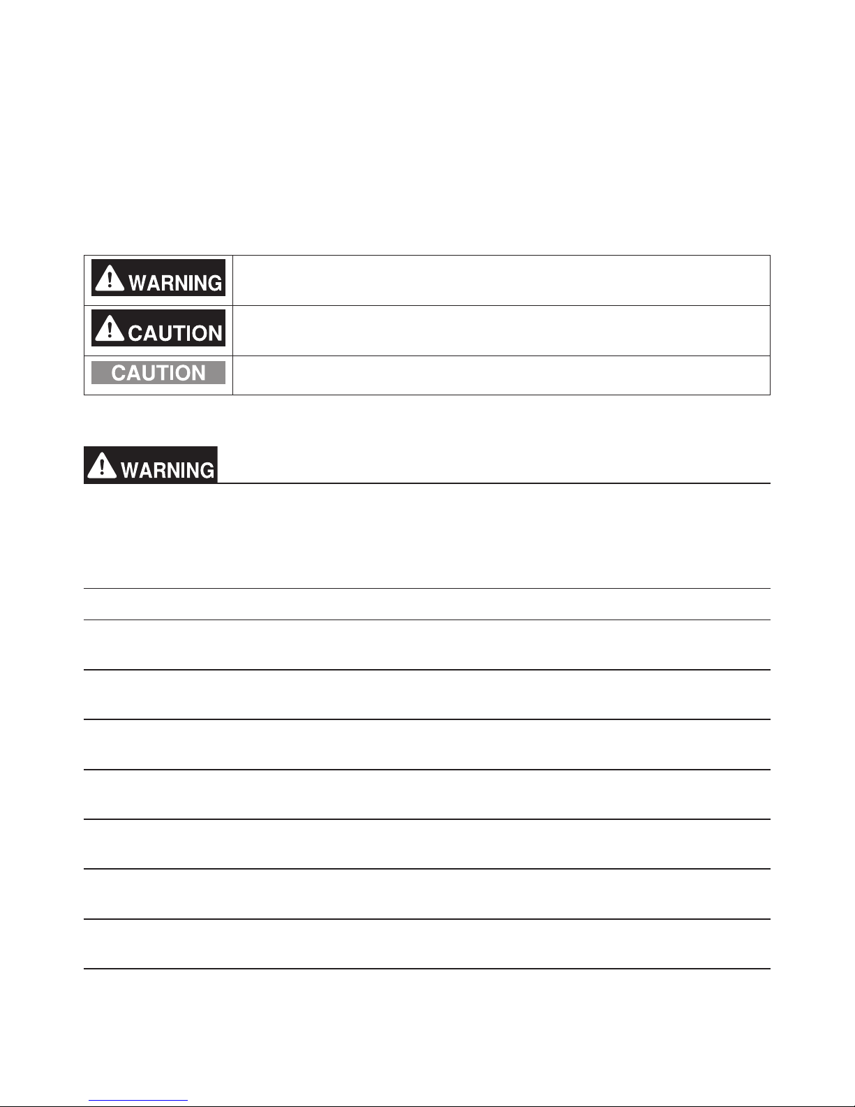
Safety notes are marked with WARNING
or
CAUTION, depending on the severity
of possible consequences that may result
when the instructions are not followed
exactly as stated.
Proper installation is important for your
safety and proper functioning of the units.
Thoroughly read the following safety
precautions prior to installation.
Contents
1. Safety precautions .......................................................................2
1-1. General precautions ....................................................................................... 2
1-2. Precautions for unit installation ....................................................................... 3
1-3. Precautions for electrical wiring ...................................................................... 3
1-4. Precautions for relocating or repairing the unit ............................................... 4
1-5. Additional precautions .................................................................................... 4
2. Introduction ..................................................................................6
2-1. Part names ..................................................................................................... 6
3. Package contents .........................................................................8
4. Specifications ...............................................................................9
4-1. Product specifications ..................................................................................... 9
4-2. External dimensions ..................................................................................... 10
4-3. Product features ............................................................................................11
5. System configuration ..................................................................14
5-1. System restrictions ....................................................................................... 14
5-2. M-NET power feeding coefficient .................................................................. 15
5-3. System configuration example ..................................................................... 16
5-4. Number of connectable units ........................................................................ 20
5-5. Setting M-NET address for various devices ................................................. 21
6. Installation ..................................................................................23
6-1. Items not included ........................................................................................ 24
6-2. Items sold separately .................................................................................... 24
6-3. M-NET transmission cable length ................................................................. 25
6-4. Installation space .......................................................................................... 26
6-5. Installation procedures ................................................................................. 27
7. Wiring connections .....................................................................30
7-1. Removing/reinstalling the service cover ....................................................... 30
7-2. Connecting AC power cables and M-NET transmission cables.................... 32
7-3. Connecting the LAN cable ............................................................................ 34
7-4. Confirming the LAN transmission delay time ................................................ 34
8. Initial settings .............................................................................36
8-1. Logging in to the Web Browser for Initial Settings ........................................ 36
8-2. Initial settings on the Web browser ............................................................... 36
8-3. Quick IP address setting ............................................................................... 37
8-4. Network settings on the Web browser .......................................................... 38
9. Test run ......................................................................................39
9-1. Collective operation ON/OFF ....................................................................... 39
10. External input/output ..................................................................40
10-1. External signal input/output function ........................................................... 40
10-2. Pulse signal input function .......................................................................... 44
11. Maintenance ...............................................................................45
11-1. Inspection and maintenance ....................................................................... 45
11-2. Back up/import settings data.......................................................................46
11-3. Software update .......................................................................................... 48
11-4. Software information ................................................................................... 51
12. Error code list .............................................................................52
12-1. M-NET errors .............................................................................................. 52
12-2. Errors between AE-200 and AE-50 (EW-50) .............................................. 54
2
WT07417X01
1. Safety precautions
►Thoroughly read the following safety precautions prior to installation.
►Observe these precautions carefully to ensure safety.
►After reading this manual, pass the manual on to the end user to retain for future
reference.
►The user should keep this manual for future reference and refer to it as necessary. This
manual should be made available to those who repair or relocate the units. Make sure
that the manual is passed on to any future air conditioning system user.
►All electrical work must be performed by qualified personnel.
: indicates a hazardous situation which, if not avoided, could result in
death or serious injury.
: indicates a hazardous situation which, if not avoided, could result in
minor or moderate injury.
: addresses practices not related to personal injury, such as product
and/or property damage.
1-1. General precautions
Do not install the controller in areas where large amounts of oil, steam, organic solvents,
or corrosive gases (such as ammonia, sulfuric compounds, or acids), or areas where
acidic/alkaline solutions or special chemical sprays are used frequently. These substances
may significantly reduce the performance and corrode the internal parts, resulting in
electric shock, malfunction, smoke, or fire.
To reduce the risk of injury, electric shock, or fire, do not alter or modify the controller.
To reduce the risk of electric shock, malfunction, smoke, or fire, do not touch the electrical
parts or USB memory with wet fingers.
To reduce the risk of injury or electric shock, before spraying a chemical around the
controller, stop the operation and cover the controller.
To reduce the risk of burns, do not touch the electrical parts with bare hands during and
immediately after operation.
To reduce the risk of injury, keep children away while installing, inspecting, or repairing the
controller.
Test runs, inspection, and service must be performed by qualified personnel in accordance
with this manual. Incorrect use may result in injury, electric shock, malfunction, or fire.
If you notice any abnormality, stop the operation and turn off the controller. Continuing the
operation may result in electric shock, malfunction, or fire.
Properly install all required covers to keep moisture and dust out of the controller. Dust
accumulation and the presence of water may result in electric shock, smoke, or fire.
To reduce the risk of frostbite, burns, injury, or electric shock, keep the equipment out of
the reach of children.
3
WT07417X01
To reduce the risk of fire or explosion, do not place flammable materials or use flammable
sprays around the controller.
To reduce the risk of electric shock or malfunction, do not touch the switches or buttons
with a sharp object.
To reduce the risk of injury, electric shock, or malfunction, avoid contact with the sharp
edges of certain parts.
To reduce the risk of injury, wear protective gear when working on the controller.
Wear protective gear when working on the controller. High-voltage parts pose a risk of
electric shock, and high-temperature parts pose a risk of burns.
1-2. Precautions for unit installation
Do not install the controller where there is a risk of flammable gas leaks. If flammable gas
accumulates around the controller, it may ignite and cause a fire or explosion.
Properly dispose of the packing materials. Plastic bags pose a suffocation hazard to
children.
Take appropriate safety measures against earthquakes to prevent the controller from
causing injury.
To prevent injury, install the controller on a flat surface strong enough to support its
weight.
To reduce the risk of short circuits, current leakage, electric shock, malfunction, smoke, or
fire, do not install the controller in a place exposed to water or in a condensing
environment.
The controller must be installed by qualified personnel according to the instructions
detailed in this manual. Improper installation may result in electric shock or fire.
1-3. Precautions for electrical wiring
To reduce the risk of malfunction, smoke, fire, or damage to the controller, do not connect
the power cable to the signal terminal block.
To reduce the risk of malfunction, smoke, fire, or damage to the controller, do not apply a
power supply voltage in excess of that specified.
Properly secure the cables in place and provide adequate slack in the cables so as not to
stress the terminals. Improperly connected cables may break, overheat, and cause smoke
or fire.
To reduce the risk of injury or electric shock, switch off the main power before performing
electrical work.
4
WT07417X01
Electrical work must be performed by qualified personnel in accordance with local
regulations and the instructions provided in this manual. Only use specified cables and
dedicated circuits. Inadequate power source capacity or improper electrical work will
result in electric shock, malfunction, or fire.
To reduce the risk of electric shock, install an overcurrent breaker and an earth leakage
breaker on the power supply. To reduce the risk of electric shock, smoke, or fire, install an
overcurrent breaker for each controller.
Only use properly rated breakers (earth leakage breaker, local switch <switch + fuse that
meets local electrical codes>, moulded case circuit breaker, or overcurrent breaker). The
use of improperly rated breakers or the substitution of fuses with steel or copper wire may
result in electric shock, malfunction, smoke, or fire.
To reduce the risk of current leakage, overheating, smoke, or fire, use properly rated
cables with adequate current carrying capacity.
Proper grounding must be provided by qualified personnel. Do not connect the protective
ground wire to a gas pipe, water pipe, lightning rod, or telephone wire. Improper grounding
may result in electric shock, smoke, fire, or malfunction due to electrical noise
interference.
To reduce the risk of short circuits, electric shock, or malfunction, keep wire pieces and
sheath shavings out of the terminal block.
To reduce the risk of short circuits, current leakage, electric shock, or malfunction, keep
the cables out of contact with controller edges.
To reduce the risk of electric shock, malfunction, or fire, seal the gap between the cable
and the end of the conduit tube with putty.
To reduce the risk of injury, do not touch the burrs of the knockout holes.
1-4. Precautions for relocating or repairing the unit
The controller must be repaired or moved only by qualified personnel. Do not disassemble
or modify the controller. Improper installation or repair may result in injury, electric shock,
or fire.
To reduce the risk of short circuits, electric shock, malfunction, or fire, do not touch the
circuit board with tools or with your hands, and do not allow dust to accumulate on the
circuit board.
1-5. Additional precautions
To avoid damage to the controller, use appropriate tools to install, inspect, or repair the
controller.
To prevent unauthorized access, always use a security device such as a VPN router when
connecting to the Internet.

5
WT07417X01
Take appropriate measures against electrical noise interference when installing the
controller in hospitals or radio communication facilities. Inverter, high-frequency medical,
or wireless communication equipment as well as power generators may cause the air
conditioning system to malfunction. The air conditioning system may also adversely affect
the operation of these types of equipment by creating electrical noise.
To avoid malfunction, do not bundle power cables and signal cables together or place
them in the same metallic conduit.
To avoid damage to the controller, do not overtighten the screws.
To avoid deformation and malfunction, do not install the controller in direct sunlight or
where the ambient temperature may exceed 55°C (131°F) or drop below -10°C (14°F).
This appliance is not intended for use by persons (including children) with reduced
physical, sensory or mental capabilities, or lack of experience and knowledge, unless they
have been given supervision or instruction concerning use of the appliance by a person
responsible for their safety. Children should be supervised to ensure that they do not play
with the appliance.
6
WT07417X01
2. Introduction
EW-50A/EW-50E is a total management system.
Any connected air conditioning systems can be operated or monitored on the Web browser. EW-50A/EW-50E can
also be used as an expansion controller of AE-200A/AE-200E.
By connecting AE-200A/AE-200E, up to 200 indoor units and other equipment can be controlled.
Hereafter, AE-200A and AE-200E, unless otherwise specified, will be called “AE-200.”
Hereafter, AE-50A and AE-50E, unless otherwise specified, will be called “AE-50.”
Hereafter, EW-50A and EW-50E, unless otherwise specified, will be called “EW-50.”
Note: A PC is required to monitor and operate the air conditioning units.
Note: The required licenses vary, depending on the functions to be used. Consult your dealer.
Note: For how to use the Web browser, refer to the Web browser instruction books (separate volume).
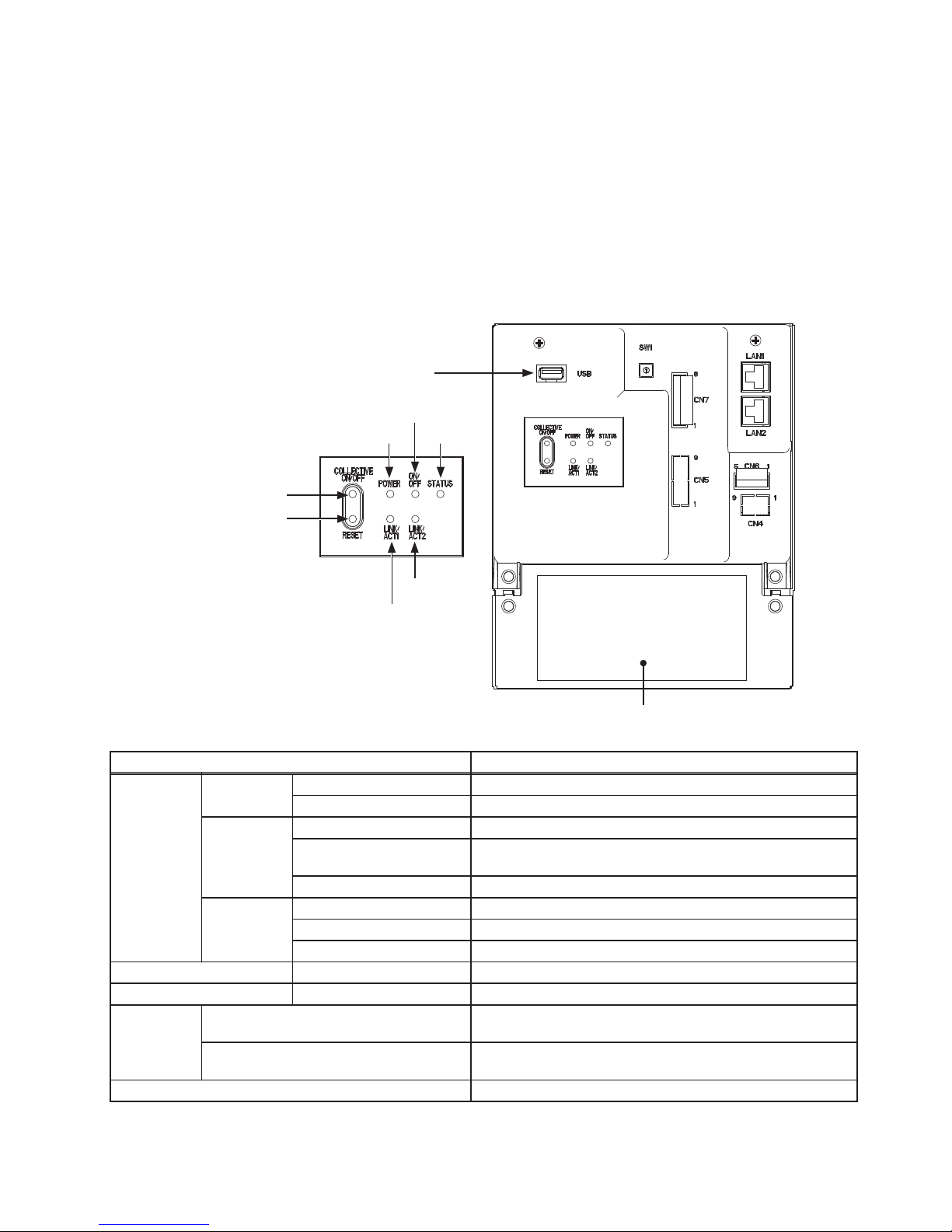
2-1. Part names
Item Description
LED
Power
Lit in green Power ON
Unlit Power OFF
ON/OFF
Lit in green One or more air conditioning units are ON.
*1
Blink in green
One or more air conditioning units or other related equipment
are in error.
Unlit All air conditioning units are OFF.
*1
Status
Blink in orange Startup error
Blink in blue Software update in progress
Blink in pink Software update failed
LINK/ACT1 Blink in orange Data transmission in progress (LAN1)
LINK/ACT2 – Unused
Push switch
ON/OFF
Used to turn the connected air conditioning units and the other
related equipment ON and OFF all at once.
Reset
Used to reboot the EW-50. (This will not affect the operation
status of the air conditioning units.)
USB port Unused
*1 The operation status of the other equipment are excluded.
USB port
(unused)
Power
LINK/ACT1
ON/OFF
LINK/ACT2
Status
Push switch ON/OFF
Service cover
Push switch Reset
7
WT07417X01
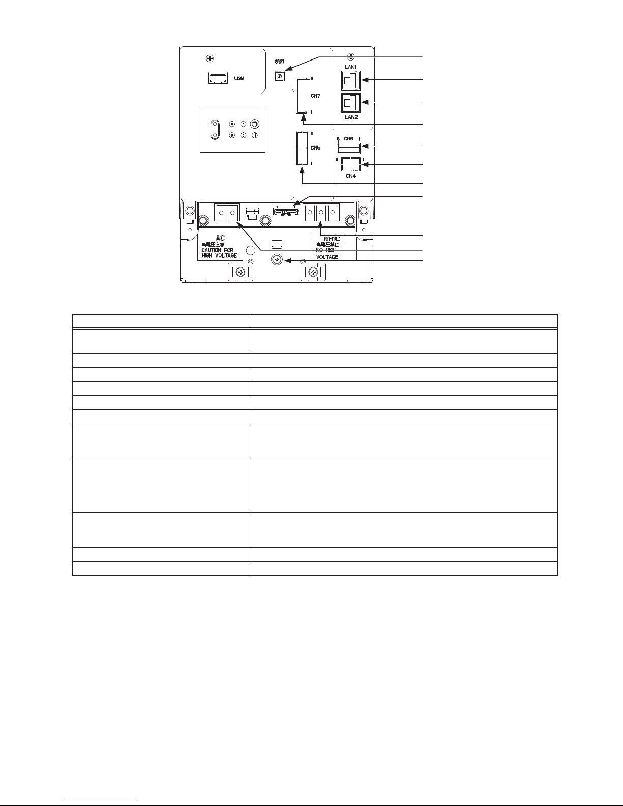
Item Description
SW1
IP addresses can be easily set with SW1. Refer to section 8-3 “Quick IP
address setting” for details.
LAN1 Connects to other units of equipment over the LAN via a HUB.
LAN2 Unused
CN7 (Pulse Input)
*1
Connects to metering devices using the supplied connector.
CN6 Unused
CN4 Unused
CN5 (External I/O)
*1
Connects to an external input/output adapter PAC-YG10HA-E.
(When connecting an external input/output adapter PAC-YG10HA-E, cut out
the knockout hole.)
CN21 (M-NET power jumper)
Connects to the M-NET power jumper to supply power (default).
* If another system controller is connected to the same M-NET system and the power
consumption coefficient is 1.5 or above, disconnect the M-NET power jumper to supply
power from the separately-sold power supply unit. (Refer to section 5-2 “M-NET power
feeding coefficient” for details.)
TB3 (M-NET A, B, S) (M3.5)
M-NET transmission terminal block
Connects to M-NET transmission cables from the outdoor unit.
(A, B: Non-polarized, S: Shield)
TB1 (Power source AC L/L1, N/L2) (M3.5) Connects to the power cable.
Ground (M4) Connects to the protective ground wire.
*1 Refer to chapter 10 “External input/output” for details.
* Back side with the service cover removed
LAN1
LAN2
(Unused)
CN7
CN6
(Unused)
CN4
(Unused)
CN5
TB3
Ground
CN21
TB1
SW1
8
WT07417X01
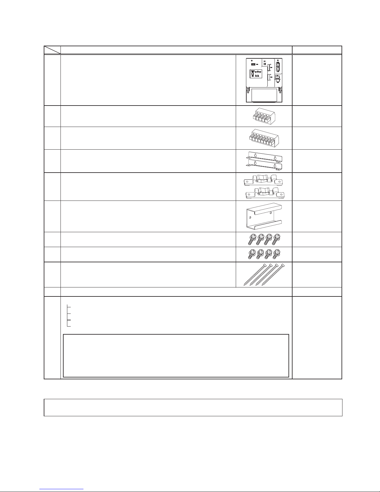
3. Package contents
The following items are included in the package.
Package contents Qty.
(1)
EW-50 1
(2)
Connector (CN6)
(Unused)
1
(3)
Connector (CN7)
(Used for pulse input)
1
(4)
L-fitting
2
(5)
DIN rail attachment
(for attaching DIN rail of 35 mm (1-7/16 in) width)
2
(6)
DIN rail auxiliary bracket 1
(7)
Roundhead screw (M3 × 12)
*1
(for fixing DIN rail attachment)
4
(8)
Roundhead screw (M3 × 6)
*1
(for fixing DIN rail auxiliary bracket or L-fitting)
4
(9)
Cable tie
4
(Two are spare.)
(10)
Installation and Instructions Manual (this manual)
*2
1
(11)
CD-ROM
*2
Installation and Instructions Manual (this manual)
Instruction Book (Web Browser for Initial Settings)
Instruction Book (Web Browser for System Maintenance Engineer)
Instruction Book (Web Browser for User)
Note
● The CD-ROM can only be played on a CD-drive or a DVD-drive. Do not attempt to play the
CD-ROM on an audio CD player as this may damage your ears and/or speakers.
● Each document is in PDF format. Viewing documents requires a computer with Adobe
®
Reader
®
or Adobe® Acrobat® installed. “Adobe® Reader®” and “Adobe® Acrobat®” are
registered trademarks of Adobe Systems Incorporated.
1
*1 ISO metric screw thread
*2 For details about the apportioned electricity billing function, refer to the Instruction Book that comes with the “Charge” license.
Notes on the SD card installed on the EW-50
● Do not use the SD card installed on the EW-50 for any other equipment.
9
WT07417X01
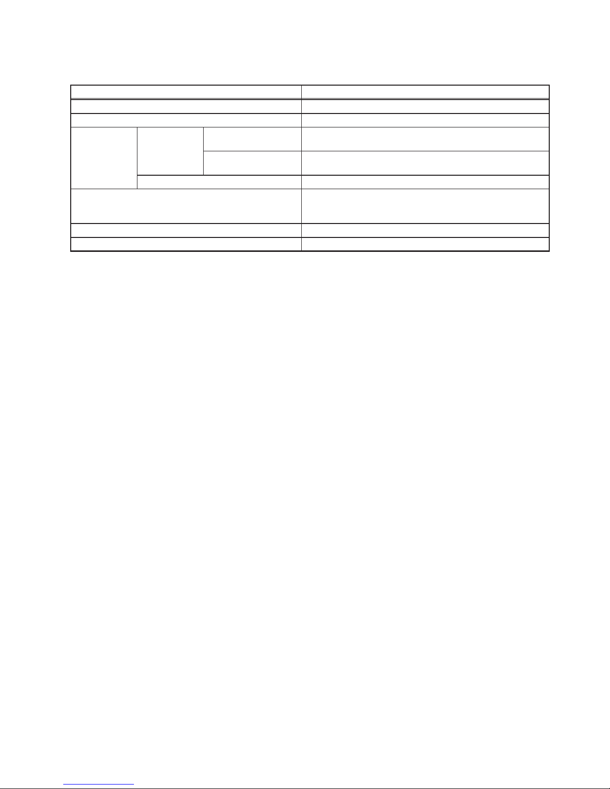
4. Specifications
4-1. Product specifications
Item Specifications
Power supply 100–240 VAC ± 10%; 50/60 Hz Single-phase
M-NET power feeding coefficient 1.5
Ambient
conditions
Temperature
Operating temperature
range
-10°C – +55°C (+14°F – +131°F)
Storage temperature
range
-20°C – +60°C (-4°F – +140°F)
Humidity 30%–90% RH (Non-condensing)
Dimensions (W × H × D)
172 × 209 × 92 mm
(6-13/16 × 8-4/16 × 3-10/16 in)
* 253 × 172 × 92 mm (10 × 6-13/16 × 3-10/16 in) when using L-fittings
Weight 1.7 kg (4 lbs)
Installation conditions Only in a metal control box indoors
10
WT07417X01
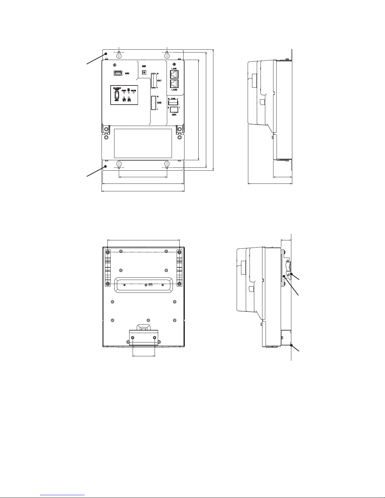
4-2. External dimensions
(1) When using L-fittings
(2) When using DIN rail
Unit: mm (in)
100 (3-15/16)
169 (6-11/16)
172 (6-13/16)
209 (8-4/16)
240 (9-8/16)
252 (9-15/16)
92 (3-10/16)
38
(1-8/16)
L-fitting
(supplied)
L-fitting
(supplied)
DIN rail attachment
(supplied)
46 (1-13/16)
DIN rail auxiliary
bracket
(supplied)
DIN rail
23 (15/16)
150 (5-15/16)

11
WT07417X01
4-3. Product features
The table below summarizes the available functions and settings on the Web browser. Refer to the Web browser
instruction books (separate volume) for details.
Function Description
User's operation functions
Operation
*1
ON/OFF The ON/OFF operation can be performed collectively or for each group or block.
Operation mode
The operation mode can be switched collectively or for each group or block. (The
available operation modes depend on the unit model.)
Set temperature
The set temperature can be set collectively or for each group or block. (The
available set temperatures depend on the unit model.)
Air direction
The air direction can be changed collectively or for each group or block. (The
available air directions depend on the unit model.)
Fan speed
The fan speed can be changed collectively or for each group or block. (The number
of available fan speeds depend on the unit model.) Auto mode is available only on
the models that support Auto mode.
Fan speed
(LOSSNAY unit)
The fan speed (3 speeds and Auto) can be changed.
Fan mode (HWHP
unit)
The fan can be set to keep rotating even while the unit is stopped to avoid snow
accumulation on the fan guard during the winter.
Ventilation mode
(LOSSNAY unit)
The ventilation mode can be switched.
Interlocked ventilator
(LOSSNAY unit)
ON/OFF
Interlocked LOSSNAY units (if any) can be operated or stopped collectively or for
each group or block.
Prohibition of local
remote controller
operation
Some operations or settings from the local remote controllers can be prohibited
collectively or for each group or block.
Filter sign reset Filter sign can be reset collectively or for each group or block.
Schedule
Weekly, annual, and today’s schedules can be set collectively or for each group or
block.
Schedule (Available/
Not Avail.)
The scheduled operations can be enabled or disabled.
Malfunction reset Displayed errors can be reset.
Clear malfunction
log
Displayed unit errors and communication errors can be cleared.
External input
Using external contact signals, the following collective operations can be controlled:
Demand level, Emergency stop, ON/OFF operation, and Prohibit/Permit local
remote controller operation.
* A separately-sold external input/output adapter (PAC-YG10HA-E) is required.
* Connect the external input/output adapter to each AE-200/AE-50/EW-50.
Monitor
*1
Energy Use Status
Displays and compares the energy-control-related status, such as electric energy
consumption, operation time, and outdoor temperature, in a graph.
Ranking
Displays the rankings in electric energy consumption and the fan operation time of
given indoor units in a bar graph.
Target Value Setting
Sets the target electric energy consumption values for the entire system for the
current year, each month, each day of the week, and each block. The set values
will be displayed in the graph on the [Energy Use Status] screen and the [Ranking]
screen.
Peakcut Control
Status
Displays the average electric power consumption and the control level.
Condition List Displays the operation status of each group.
Prohibition of local
remote controller
operation
Displays the icon to indicate that the operation is prohibited by the EW-50.
Measurement List
Displays the readings of the temperature sensor, humidity sensor, and metering
device.
12
WT07417X01
Function Description
User’s operation functions
Monitor
*1
Malfunction List Displays the address of the unit in error and error code.
Filter sign Indicates that the filter on the unit in a given group is due for cleaning.
AHC List Displays the input and output status of Advanced HVAC CONTROLLERs.
Free Contact List Displays the ON/OFF status of the indoor unit free contact.
Malfunction Log Displays unit errors and communication errors.
Send Mail Log Displays a list of error notification e-mail that have been sent.
Outdoor unit status
Displays outdoor unit capacity value, high pressure, and low pressure of each
outdoor unit.
External output
Outputs signals (ON/OFF, Error) to an external device.
* A separately-sold external input/output adapter (PAC-YG10HA-E) is required.
* The operation status of general equipment (via a DIDO controller (PAC-YG66DCA)) will not
be output.
Initial settings
Operation
*1
Date and time Sets the current date/time and daylight savings time.
License Registers license for optional functions.
Basic System
Sets unit name, unit ID, IP address, subnet mask, gateway, display format, M-NET
address, range of prohibited controllers, external input setting, and advanced
setting.
Groups
Registers air conditioning units, Air To Water (PWFY) units, LOSSNAY units, general
equipments, remote controllers, and sub system controllers to a group.
Interlocked
LOSSNAY
Interlocks the operation of indoor units and LOSSNAY units.
Blocks Registers groups to a block.
Function settings
Functions 1
*1
E-Mail
The e-mail server information, EW-50 e-mail information, and e-mail settings for the
error notification e-mail function and e-mail communication function can be set.
Peak Cut The Peak Cut method and control settings for outdoor and indoor units can be set.
Measurement
AI and PI controllers, temperature sensor, humidity sensor, and metering device can
be registered. The trend data format, error notification e-mail function settings, and
e-mail alarm function settings can be set.
Energy
Management
Settings
The settings related to energy-use-status display can be made.
Functions 2
*1
Set Temperature
Range Limit
The settable temperature range can be set.
Night Mode
Schedule
The start/end times for the Night mode (quiet operation) for outdoor units can be set.
System-changeover
This function switches the operation modes of the indoor units connected to the
same outdoor unit between cooling and heating based on the room temperature and
the set temperature. The target outdoor units and details for this function can be set.
Functions 3
*1
External
Temperature
Interlock
This function adjusts the set temperature based on the temperature difference
between the set temperature and the outdoor temperature. A maximum temperature
value to be added to the set temperature can be set for each group.
Night Setback
Control
This function performs cooling or heating operation when the room temperature
goes outside of the specified temperature range. The start/end times and
temperature range can be set for each group.
Interlock control
Interlock control between the connected devices can be performed by making
various settings. Up to 150 interlocking conditions can be set.
AHC Port Name
Settings
The names of the AHC analog/digital input/output ports can be set.
User settings
User settings
Maintenance user User name and password for maintenance users can be set.
Building manager User name, password, and available functions to building managers can be set.
13
WT07417X01
Function Description
Miscellaneous
Back up settings data Backed-up settings data can be restored from the PC.
Import settings data Backed-up settings data can be restored from a PC.
Group setting information/
Interlocked LOSSNAY information
The group setting information and interlocked LOSSNAY information are retained in
the hardware, even if power is turned off.
Malfunction log The malfunction log is retained in the hardware, even if power is turned off.
Scheduled operations
The scheduled operations set for each group are retained in the hardware, even if
power is turned off.
Current date and time
The current date and time are retained by the built-in capacitor when power is
turned off.
CSV output
The operation data, such as apportioning parameters and power consumption, can
be output.
Software Update
The software can be updated by inserting a CD or USB memory device in which the
update file is stored to a PC.
Time synchronization
Clocks on the controllers and the units that are under the control of the main system
controller are synchronized once a day (applicable only to the ones that support this
function).
*1 The item and range that can be operated or monitored depend on the unit model.
14
WT07417X01
5. System configuration
5-1. System restrictions
The software version of the AE-200, AE-50, and EW-50 units in a system must be the same. For details about how
to update the software, refer to section 11-3 “Software update”.
The restrictions vary, depending on the number of the controlled units, model of the connected units, and the
functions in use.
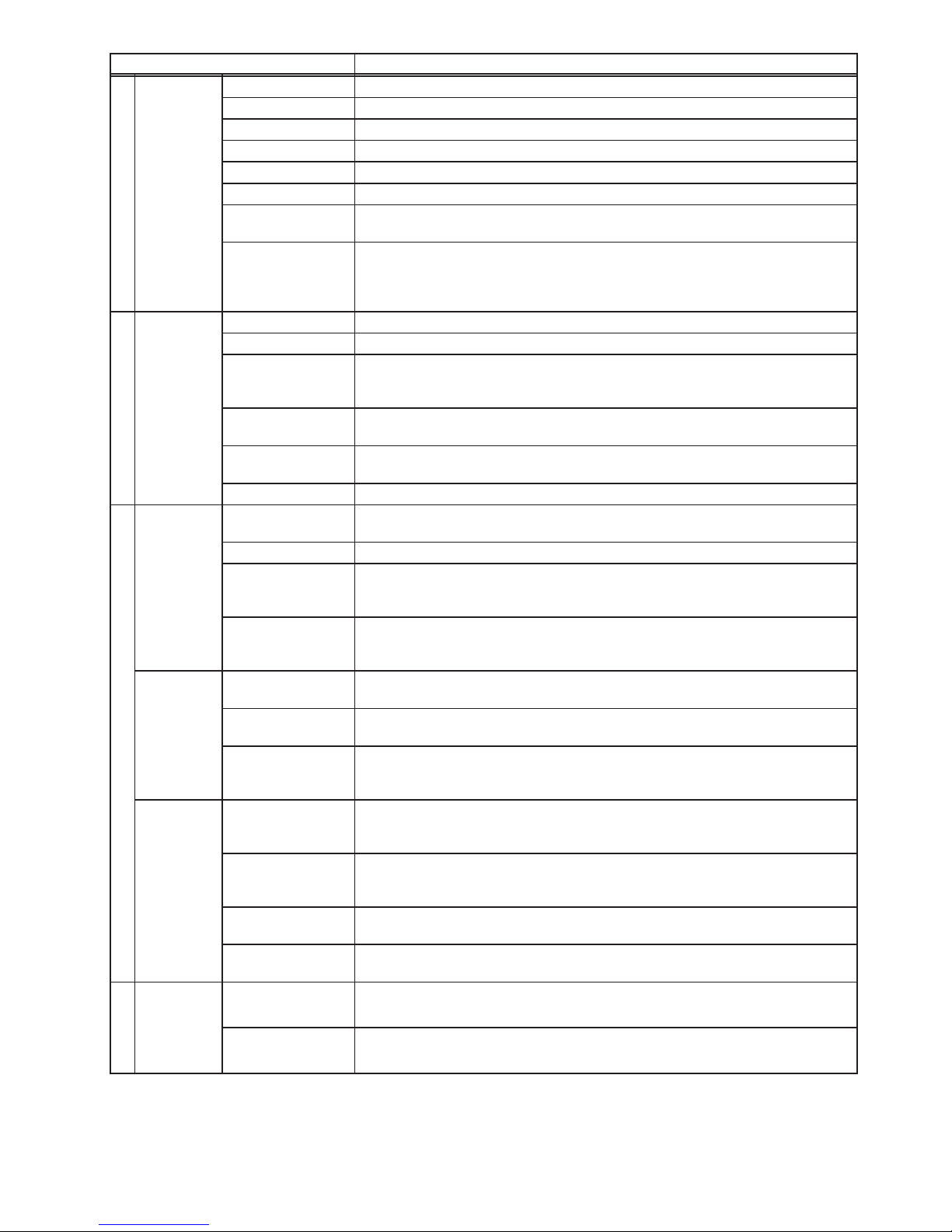
5-1-1. When not using an apportioned electricity billing function
Note: AE-200 is required when using AE-50.
(1) Controlling 50 or fewer units of equipment
1. AE-200
2. EW-50
M-NET
AE-200
M-NET
EW-50
(2) Controlling more than 50 units of equipment (with connection to an AE-200 controller)
M-NET
M-NET
M-NET
M-NET
AE-200
AE-50
EW-50
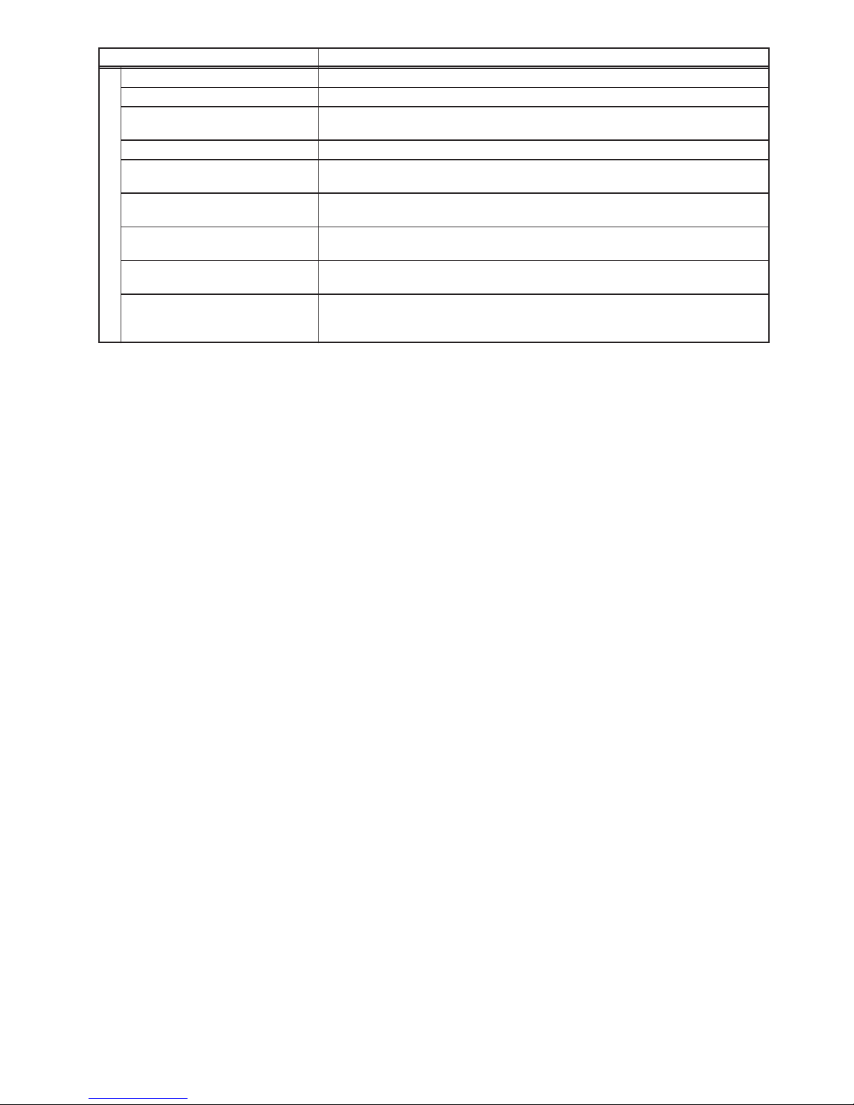
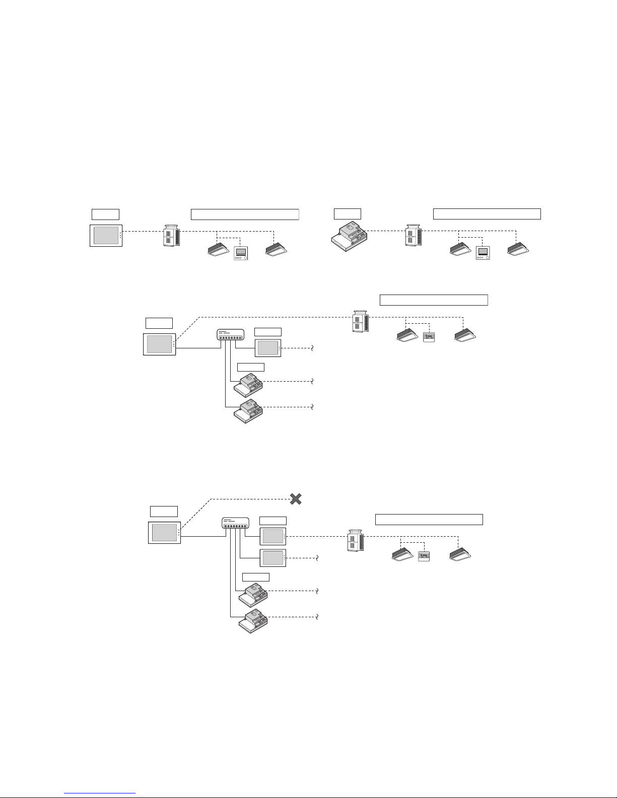
5-1-2. When using an apportioned electricity billing function
Note: AE-200 is required to use a billing function.
Note: AE-200 M-NET cannot be used when a billing function is used.
Note: “Charge” license is required to use a billing function.
M-NET
M-NET
M-NET
M-NET
M-NET
AE-200
AE-50
EW-50
Outdoor unit
Indoor unit
Remote controller
Outdoor unit
City Multi system
City Multi system
Remote controller
Indoor unit
Outdoor unit
Indoor unit
Remote controller
HUB
City Multi system
City Multi system
HUB
Remote controller
Outdoor unit
Indoor unit
15
WT07417X01
5-2. M-NET power feeding coefficient
The EW-50’s power feeding coefficient is 1.5.
A power supply unit is not required when the power consumption coefficient of the M-NET equipment (e.g. system
controller, PI controller) that will be connected to the centralized control transmission cables is 1.5 or below.
Power feeding coefficient
Product Power feeding coefficient
EW-50 1.5
Power supply unit (PAC-SC51KUA) 5
Power consumption coefficient
Product Power consumption coefficient
DIDO controller (PAC-YG66DCA) 1/4
PI controller (PAC-YG60MCA) 1/4
AI controller (PAC-YG63MCA) 1/4
System controller
(North America: TC-24B, Europe: AT-50B)
1.5
ON/OFF remote controller (PAC-YT40ANRA) 1
Use a power supply unit and connect the M-NET power jumper as shown in the table below, depending on the
system configuration and the power consumption coefficient of the M-NET equipment that will be connected to the
centralized control transmission cables.
Power supply unit M-NET power jumper (CN21)
System with connection to a
sub system controller or other
related equipment
Power consumption
coefficient ≤ 1.5
Not required
Connect
(Connected at factory shipment)
Power consumption
coefficient > 1.5
Required Disconnect
* Leave the M-NET power jumper connected to CN41 on all outdoor units.
* Provide a single point ground for the shield of the centralized control transmission cable. (Provide the appropriate grounding according to
local standards.) Refer to section 7-2-2 “M-NET transmission cables (Centralized control transmission cables)” for details.
* Set the centralized control switch (SW5-1 (or SW2-1, depending on the unit model)) on the outdoor unit connected to the M-NET
transmission cable to ON.
* Refer to section 2-1 “Part names” for the location of CN21.
16
WT07417X01
5-3. System configuration example
Note
● The figures in (1) through (3) below only show the transmission cable connections. Power cables are omitted.
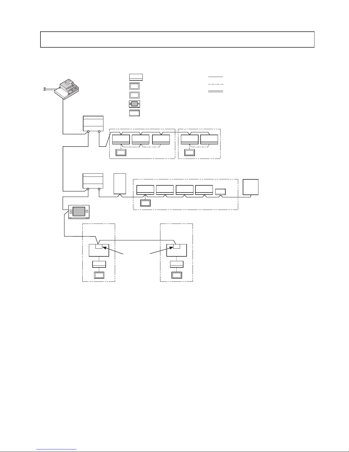
(1) When the power consumption coefficient of the M-NET equipment that will be connected to the
centralized control transmission cables is 1.5 or below
TB7 TB3
TB7 TB3
MA
ME
MA
[051]
[056
]
[11] [12]
MA
M-NET
M-NET
EW-50
[000]
[057]
LOSSNAY
MA
[004] [005][001] [002] [003]
[006] [007] [008] [009] [010]
[106]
[201]
ME
MA
AHC
AHC
[201]
*1 Leave the M-NET power jumper connected to CN21 on the EW-50.
*2 Leave the M-NET power jumper connected to CN41 on all outdoor units.
*3 An M-NET adapter (sold separately) is required to connect the Mr. Slim model of units to the M-NET.
LAN
*1
Outdoor unit (Y)
*2
Group 1
Outdoor unit (R2)
*2
BC controller
Mr. Slim
outdoor unit
Group 2
Group 3
M-NET adapter
Indoor unit
Local remote controller (MA R/C type)
Local remote controller (ME R/C type)
M-NET transmission cable
MA remote controller cable
Numbers in parentheses indicate address
numbers.
Sub system controller
*3
LAN cable
Mr. Slim
outdoor unit
Group 4
*3
Group 5
Advanced HVAC CONTROLLER
17
WT07417X01
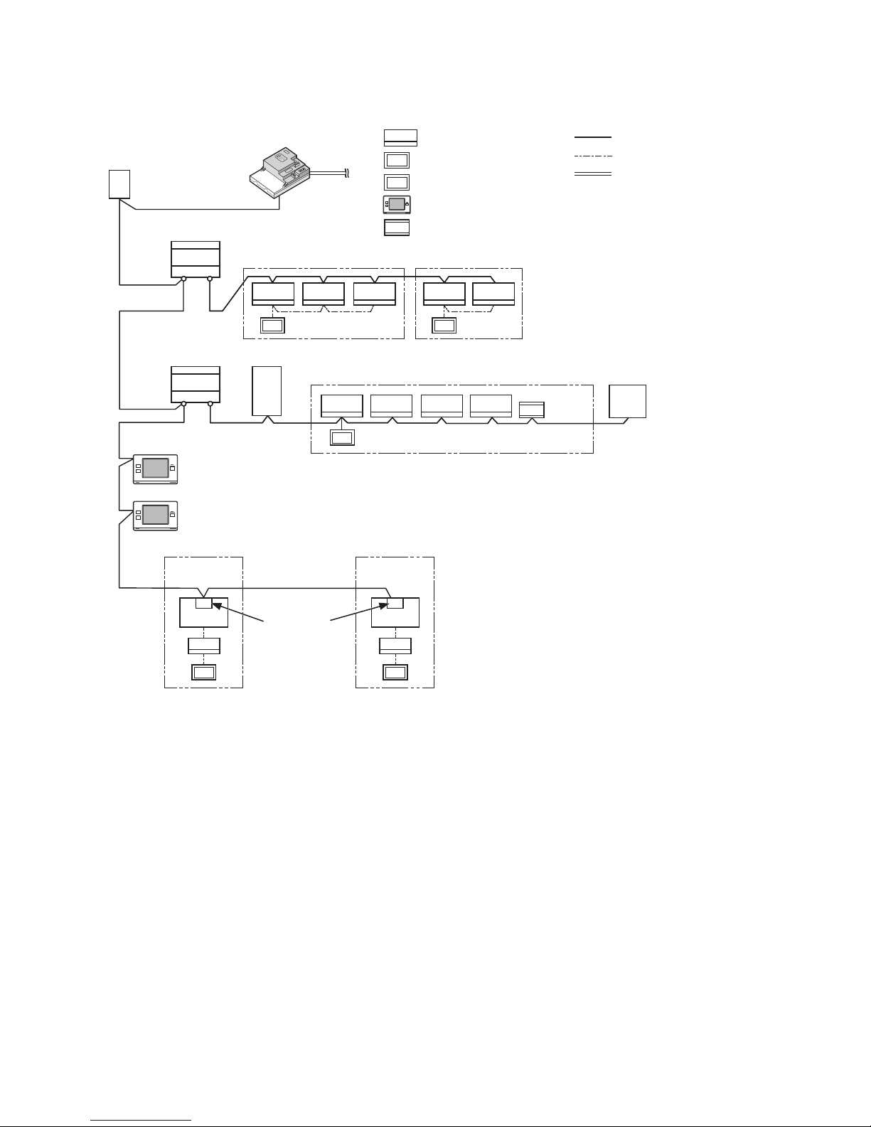
(2) When the power consumption coefficient of the M-NET equipment that will be connected to the
centralized control transmission cables is greater than 1.5
Example: When two system controllers (North America: TC-24B, Europe: AT-50B) (power consumption coefficient: 1.5
each) are connected, the power consumption coefficient is 3. In this case, use a power supply unit.
[201]
[202]
LAN
EW-50
[000]
LOSSNAY
TB7 TB3
TB7 TB3
M-NET
[051]
[056]
ME
[006] [007] [008] [009] [010]
[106]
MAMA
[004] [005][001] [002] [003]
[11]
MA
[057]
M-NET
M-NET
[12]
MA
ME
MA
AHC
AHC
[201]
*1 Disconnect the M-NET power jumper (CN21) from the EW-50.
*2 Leave the M-NET power jumper connected to CN41 on all outdoor units.
*3 An M-NET adapter (sold separately) is required to connect the Mr. Slim model of units to the M-NET.
*1
Outdoor unit (Y)
*2
Group 1
Outdoor unit (R2)
*2
BC controller
Mr. Slim
outdoor unit
Group 2
Group 3
M-NET adapter
Indoor unit
Local remote controller (MA R/C type)
Local remote controller (ME R/C type)
M-NET transmission cable
MA remote controller cable
Numbers in parentheses indicate address
numbers.
Sub system controller
*3
LAN cable
Mr. Slim
outdoor unit
Group 4
*3
Group 5
Power supply unit
PAC-SC51KUA
(sold separately)
Advanced HVAC CONTROLLER
18
WT07417X01
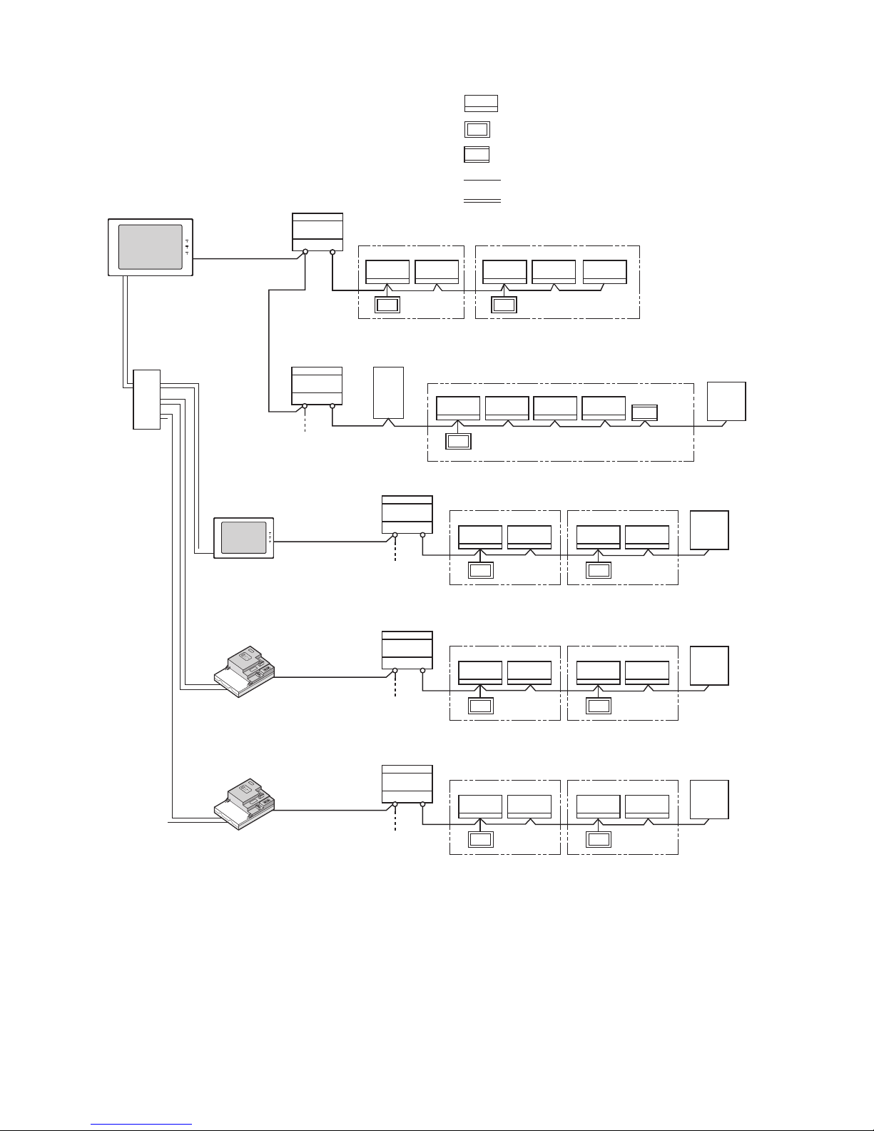
(3) When connecting AE-50/EW-50 controllers (up to four controllers) to an AE-200
1. When not using an apportioned electricity billing function
LOSSNAY
LOSSNAY
TB7 TB3
TB7 TB3
ME ME
ME
[051]
[056] [057]
[001] [002] [003] [004] [005]
[006] [007] [008] [009] [010]
[106]
M-NET
LAN
LAN
LAN
LAN
M-NET
M-NET
TB7 TB3
ME
[051]
[001] [002] [003] [004] [005]
[101]
TB7 TB3
ME
[051]
[001] [002] [003] [004] [005]
[101]
ME
[103]
[101] [103]
ME
[103]
LOSSNAY
M-NET
TB7 TB3
ME
[051]
[001] [002] [003] [004] [005]
[101]
ME
[103]
LOSSNAY
AE-200
[000]
AE-50
[000]
EW-50
[000]
EW-50
[000]
ME
AHC
AHC
[201]
*1 Leave the M-NET power jumper connected to CN21 on the AE-200 and EW-50.
*2 Leave the M-NET power jumper connected to CN41 on all outdoor units.
LAN1 IP: 192.168.1.001
*1
Switching
HUB
Outdoor unit (Y)
Outdoor unit (R2)
Group 1
LAN1 IP: 192.168.1.211
BC controller
Outdoor unit
Group 2
Group 3
Group 1
LAN1 IP: 192.168.1.212
Indoor unit
Local remote controller (ME R/C type)
M-NET transmission cable
Outdoor unit
Numbers in parentheses indicate address
numbers.
Group 2
Group 1
LAN1 IP: 192.168.1.213
Outdoor unit
Group 2
Group 1 Group 2
*1
LAN cable
*1
*1
*2
*2
*2
*2
Advanced HVAC CONTROLLER
*2
 Loading...