

Page 1

Air Conditioning Control System
Centralized Controller
AE-200A/AE-50A/EW-50A
AE-200E/AE-50E/EW-50E
–Apportioned Electricity Billing Function–
Contents
Safety precautions .......................................................................................... 5
1. Parts to be used ......................................................................................7
1-1. Supplied parts ................................................................................................ 7
1-2. Separately sold parts ..................................................................................... 7
1-3. Commercially available parts ......................................................................... 7
1-4. PC requirements ............................................................................................ 8
1-5. Version restrictions ......................................................................................... 8
2. Introduction .............................................................................................. 9
2-1. About apportioned electricity billing function .................................................. 9
2-2. System overview ...........................................................................................11
2-3. Selecting the operation method ................................................................... 12
2-4. Function list .................................................................................................. 13
2-5. System restrictions ....................................................................................... 14
2-6. Notes on using the apportioned electricity billing function ........................... 14
3. Basic operations .................................................................................... 16
3-1. Specified date calculation (LAN connection) ............................................... 16
3-2. Specified date calculation (USB) ................................................................. 18
3-3. Closing date calculation (automatic output) ................................................. 25
3-4. Displaying charge calculation results ........................................................... 30
3-5. Printing the charge calculation results ......................................................... 32
3-6. Examples of charge calculation results CSV output .................................... 34
4. Practical operations ............................................................................... 36
4-1. Settings for the Charge Calculation Tool ...................................................... 36
4-2. Calculating the charges for 2 months ago or earlier .................................... 40
4-3. Other setting changes and precautions ....................................................... 41
4-4. Displaying energy management data .......................................................... 43
5. Preparation of the software (installation) ............................................... 45
5-1. Installation procedures of the Charge Calculation Tool ................................ 45
5-2. Installation procedures of the Initial Setting Tool .......................................... 47
5-3. Setting the PC’s IP address ......................................................................... 49
5-4. Installation procedures of .NET Framework ................................................. 51
6. Initial settings ......................................................................................... 52
6-1. General descriptions .................................................................................... 52
6-2. Settings on the AE-200 for billing function ................................................... 55
6-3. Settings on the Initial Setting Tool ................................................................ 58
6-4. General descriptions of Initial Setting Tool ................................................... 61
6-5. Basic settings ............................................................................................... 68
6-6. Unit settings ................................................................................................. 74
6-7. Billing function settings ................................................................................ 84
6-8. Settings on the Charge Calculation Tool ...................................................... 98
7. Billing function trial run ..........................................................................99
7-1. Flow of the billing function trial run ............................................................. 100
7-2. Checking the billing function settings (check before billing function
trial run) ..................................................................................................... 102
7-3. Billing function trial run checks ................................................................... 108
Before using the controller,
please read this Instruction
Book carefully to ensure proper
operation.
Retain this manual for future
reference.
7-4. Final checks ................................................................................................114
8. Troubleshooting ................................................................................... 11 5
8-1. Troubleshooting ..........................................................................................115
8-2. Logging in to the Maintenance screen ........................................................118
8-3. Replacing the AE-200 .................................................................................119
8-4. Replacing the AE-50/EW-50 ......................................................................120
8-5. Replacing the PI controller ......................................................................... 122
8-6. Other Tasks ................................................................................................ 123
Appendix 1. Using the AE-200 Charge Calculation Support Tool ...............125
Instruction Book
Page 2

Contents
Safety precautions ..................................................................................................... 5
1. Parts to be used .................................................................................................. 7
1-1. Supplied parts ......................................................................................................... 7
1-2. Separately sold parts .............................................................................................. 7
1-3. Commercially available parts .................................................................................. 7
1-4. PC requirements ..................................................................................................... 8
1-5. Version restrictions .................................................................................................. 8
2. Introduction .........................................................................................................9
2-1. About apportioned electricity billing function ........................................................... 9
2-2. System overview ................................................................................................... 11
2-3. Selecting the operation method ............................................................................ 12
2-4. Function list ........................................................................................................... 13
2-5. System restrictions ................................................................................................ 14
2-6. Notes on using the apportioned electricity billing function .................................... 14
3. Basic operations ................................................................................................ 16
3-1. Specified date calculation (LAN connection) ........................................................ 16
3-1-1. Preparation of the PC ................................................................................. 16
3-1-2. Making the settings for the Charge Calculation Tool ..................................16
3-2. Specified date calculation (USB) .......................................................................... 18
3-2-1. Preparation of the PC ................................................................................. 18
3-2-2. Data acquisition using USB memory .......................................................... 18
3-2-3. Making the settings for the Charge Calculation Tool ..................................21
3-3. Closing date calculation (automatic output) .......................................................... 25
3-3-1. Preparation of the PC ................................................................................. 25
3-3-2. Making the settings for the Charge Calculation Tool ..................................26
3-3-3. Settings on the Charge Calculation Tool ....................................................27
3-4. Displaying charge calculation results .................................................................... 30
3-4-1. Systems where electric energy is metered (with-metering-device
method)....................................................................................................... 30
3-4-2. Systems where electric energy is entered manually (no-metering-device
method)....................................................................................................... 31
3-5. Printing the charge calculation results .................................................................. 32
3-5-1. Systems where electric energy is metered (with-metering-device
method)....................................................................................................... 32
3-5-2. Systems where electric energy is entered manually (no-metering-device
method)....................................................................................................... 33
3-6. Examples of charge calculation results CSV output ............................................. 34
3-6-1. Systems where electric energy is metered (with-metering-device
method)....................................................................................................... 34
3-6-2. Systems where electric energy is entered manually (no-metering-device
method)....................................................................................................... 35
WT07442X02
2
Page 3

4. Practical operations ........................................................................................... 36
4-1. Settings for the Charge Calculation Tool ...............................................................36
4-1-1. Making the settings for the Charge Calculation Tool ..................................36
4-1-2. Charge Calculation Tool settings ................................................................ 37
4-1-3. Saving the settings ..................................................................................... 39
4-2. Calculating the charges for 2 months ago or earlier ............................................. 40
4-2-1. Periodically saving USB output to a PC ..................................................... 40
4-3. Other setting changes and precautions ................................................................ 41
4-3-1. Changing the closing date .......................................................................... 41
4-3-2. Changing the unit price (special day, seasonal) ......................................... 41
4-3-3. Changing the tenant name ......................................................................... 41
4-3-4. Changing the tenant (energy management block) floor plan ..................... 42
4-4. Displaying energy management data ................................................................... 43
5. Preparation of the software (installation) ...........................................................45
5-1. Installation procedures of the Charge Calculation Tool .........................................45
5-2. Installation procedures of the Initial Setting Tool ...................................................47
5-3. Setting the PC’s IP address .................................................................................. 49
5-3-1. For Windows 7............................................................................................ 49
5-3-2. For Windows 8.1......................................................................................... 50
5-4. Installation procedures of .NET Framework ..........................................................51
6. Initial settings .................................................................................................... 52
6-1. General descriptions ............................................................................................. 52
6-1-1. Flow of the initial settings and billing function trial run ............................... 52
6-1-2. Required settings to use an apportioned electricity billing function ............ 53
6-2. Settings on the AE-200 for billing function ............................................................55
6-2-1. Settings on the AE-200 ............................................................................... 55
6-2-2. AE-200 unit settings.................................................................................... 56
6-3. Settings on the Initial Setting Tool ......................................................................... 58
6-3-1. Setting items ............................................................................................... 59
6-3-2. Flow of the initial settings on Initial Setting Tool .........................................60
6-4. General descriptions of Initial Setting Tool ............................................................ 61
6-4-1. Starting up the Initial Setting Tool ............................................................... 61
6-4-2. Screen configurations and common items ................................................. 62
6-4-3. List of tool bar operations ........................................................................... 63
6-4-4. Unit address selection screen .................................................................... 66
6-4-5. Other settings ............................................................................................. 66
6-4-6. Preparation and flow of the Initial Setting Tool ...........................................67
6-5. Basic settings ........................................................................................................ 68
6-5-1. System Configuration settings .................................................................... 68
6-5-2. Basic System settings ................................................................................ 69
WT07442X02
3
Page 4

6-6. Unit settings .......................................................................................................... 74
6-6-1. Group settings ............................................................................................ 74
6-6-2. Refrigerant System settings ....................................................................... 76
6-6-3. Interlocked LOSSNAY settings ................................................................... 77
6-6-4. Block settings ............................................................................................. 78
6-6-5. Energy management block settings ........................................................... 79
6-6-6. PI controller settings ................................................................................... 81
6-6-7. AI controller settings ................................................................................... 82
6-7. Billing function settings ......................................................................................... 84
6-7-1. Billing function settings ............................................................................... 84
6-7-2. Outdoor unit settings .................................................................................. 87
6-7-3. Indoor unit settings ..................................................................................... 88
6-7-4. Measurement settings ................................................................................ 90
6-7-5. Charges settings......................................................................................... 92
6-8. Settings on the Charge Calculation Tool ............................................................... 98
7. Billing function trial run ......................................................................................99
7-1. Flow of the billing function trial run ...................................................................... 100
7-2. Checking the billing function settings (check before billing function trial run) ..... 102
7-2-1. Billing-related item sheet .......................................................................... 102
7-2-2. Unit-related item sheet ............................................................................. 105
7-2-3. Entering the electric energy ...................................................................... 107
7-3. Billing function trial run checks ............................................................................ 108
7-3-1. 1st run check (after air conditioning unit continuous operation) ............... 108
7-3-2. 2nd run check (at least 10 days after 1st billing function trial run) ........... 113
7-3-3. 3rd run check (at least 1 month after the 2nd billing function trial run) ..... 113
7-4. Final checks ........................................................................................................ 114
7-4-1. Final checks for the operation settings ..................................................... 114
7-4-2. Final report ............................................................................................... 114
8. Troubleshooting ............................................................................................... 115
8-1. Troubleshooting .................................................................................................. 115
8-2. Logging in to the Maintenance screen ................................................................ 118
8-3. Replacing the AE-200 ......................................................................................... 119
8-4. Replacing the AE-50/EW-50 ............................................................................... 120
8-5. Replacing the PI controller .................................................................................. 122
8-6. Other Tasks ......................................................................................................... 123
Appendix 1. Using the AE-200 Charge Calculation Support Tool .......................... 125
WT07442X02
4
Page 5
Safety precautions
►Observe these precautions carefully to ensure safety.
►After reading this manual, pass the manual on to the end user to retain for future
reference.
►The user should keep this manual for future reference and refer to it as necessary. This
manual should be made available to those who repair or relocate the units. Make sure
that the manual is passed on to any future air conditioning system user.
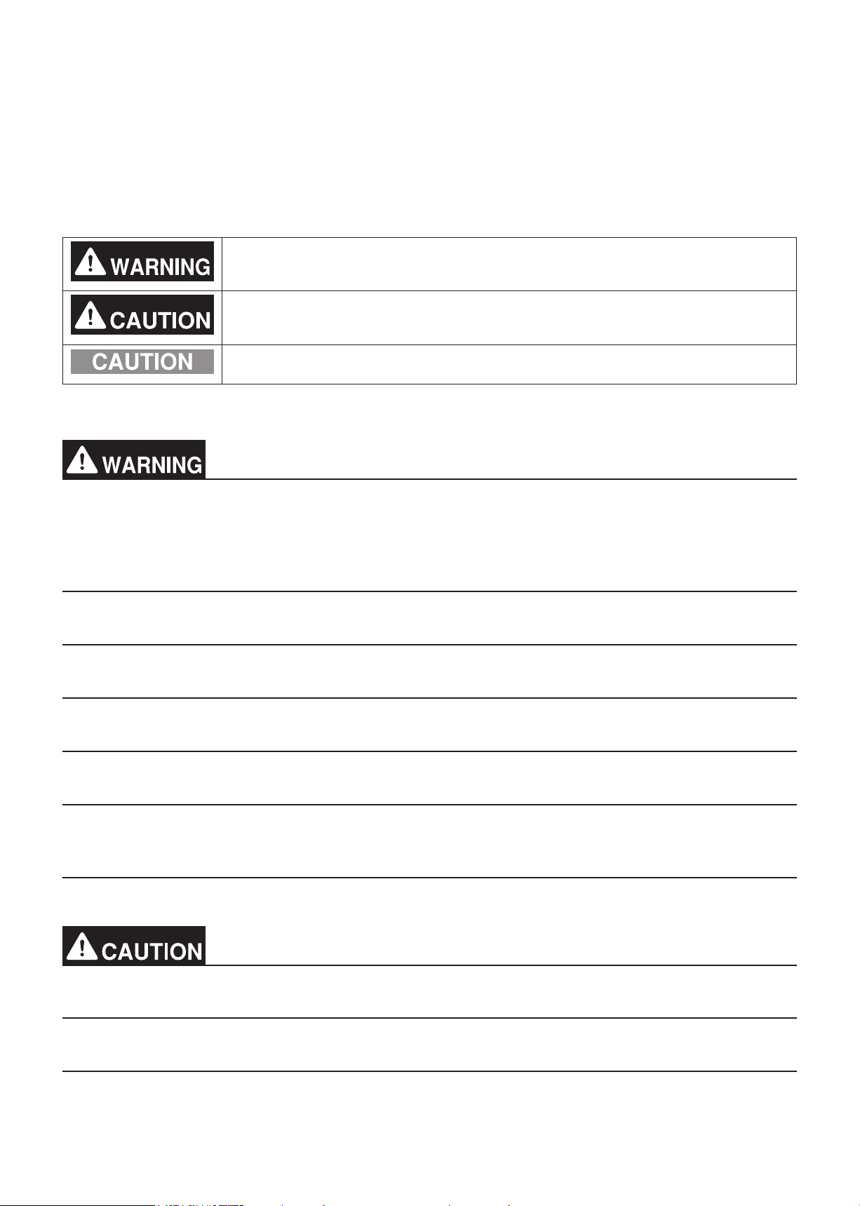
: indicates a hazardous situation which, if not avoided, could result in
death or serious injury.
: indicates a hazardous situation which, if not avoided, could result in
minor or moderate injury.
: addresses practices not related to personal injury, such as product
and/or property damage.
General precautions
Do not install the controller in areas where large amounts of oil, steam, organic solvents,
or corrosive gases (such as ammonia, sulfuric compounds, or acids), or areas where
acidic/alkaline solutions or special chemical sprays are used frequently. These substances
may significantly reduce the performance and corrode the internal parts, resulting in
electric shock, malfunction, smoke, or fire.
To reduce the risk of short circuits, current leakage, electric shock, malfunction, smoke, or
fire, do not wash the controller with water or any other liquid.
To reduce the risk of electric shock, malfunction, smoke, or fire, do not touch the electrical
parts, USB memory, or touch panel with wet fingers.
To reduce the risk of injury or electric shock, before spraying a chemical around the
controller, stop the operation and cover the controller.
To reduce the risk of injury, keep children away while installing, inspecting, or repairing the
controller.
If you notice any abnormality (e.g., burning smell), stop the operation, turn off the
controller, and consult your dealer. Continuing the operation may result in electric shock,
malfunction, or fire.
Properly install all required covers to keep moisture and dust out of the controller. Dust
accumulation and the presence of water may result in electric shock, smoke, or fire.
To reduce the risk of fire or explosion, do not place flammable materials or use flammable
sprays around the controller.
To reduce the risk of electric shock or malfunction, do not touch the touch panel, switches,
or buttons with a sharp object.
To avoid injury from broken glass, do not apply excessive force to the glass parts.
WT07442X02
5
Page 6

To reduce the risk of injury, electric shock, or malfunction, avoid contact with the sharp
edges of certain parts.
Consult your dealer for the proper disposal of the controller. Improper disposal will pose a
risk of environmental pollution.
Precautions for relocating or repairing the unit
The controller must be repaired or moved only by qualified personnel. Do not disassemble
or modify the controller. Improper installation or repair may result in injury, electric shock,
or fire.
Additional precautions
To avoid discoloration, do not use benzene, thinner, or chemical rag to clean the controller.
When the controller is heavily soiled, wipe the controller with a well-wrung cloth that has
been soaked in water with mild detergent, and then wipe off with a dry cloth.
This appliance is not intended for use by persons (including children) with reduced
physical, sensory or mental capabilities, or lack of experience and knowledge, unless they
have been given supervision or instruction concerning use of the appliance by a person
responsible for their safety. Children should be supervised to ensure that they do not play
with the appliance.
Terms used in this manual
- “Microsoft® Windows® 7 Home Premium” is referred to as “Windows 7”, and “Microsoft® Windows® 8.1” is referred
to as “Windows 8.1”.
- “Centralized Controller AE-200A/AE-200E” is referred to as “AE-200”.
- “Centralized Controller AE-50A/AE-50E” is referred to as “AE-50”.
- “Centralized Controller EW-50A/EW-50E” is referred to as “EW-50”.
- “DIDO controller (PAC-YG66DCA)” is referred to as “DIDO controller”.
- “PI controller (PAC-YG60MCA)” is referred to as “PI controller”.
- “AI controller (PAC-YG63MCA)” is referred to as “AI controller”.
- “OA Processing unit (LOSSNAY with heater and humidifier)” is referred to as “LOSSNAY with heater and
humidifier”.
- “Booster unit” and “Water HEX unit” are referred to as “Air To Water (PWFY) unit”.
- “Advanced HVAC CONTROLLER” is referred to as “AHC”.
- “Hot Water Heat Pump unit” is referred to as “HWHP (CAHV, CRHV) unit”.
WT07442X02
6
Page 7
1. Parts to be used
1-1. Supplied parts
Before using this product, check that the parts listed below are included with your product.
No. Item Qty
(1) Instruction Book (this manual) 1
(2) “Charge” license 1 for each AE-200/AE-50/EW-50
(3) Initial Setting Tool 1
(4) Charge Calculation Tool 1
1-2. Separately sold parts
Use only genuine Mitsubishi Electric products for the components listed below.
Item Model Qty
PI controller PAC-YG60MCA Required number
Surface cover with USB port PAC-YG72CWL-J 1 for each AE-200 unit
1-3. Commercially available parts
Where necessary, prepare the commercially available parts listed below.
Item Qty Remarks
Electricity meter Required number
Pulse width: 100-300 ms
Pulse weight: 0.1 kWh/pulse, 1.0 kWh/pulse
recommended
Pulse detector Required number
DC power unit
AC power cable As appropriate For DC power units
For PI controller
Communicationrelated
*1 When using an external 24 VDC power unit, specify and use a product that meets the UL60950-1 or EN60950-1 safety standard. (Product
with enhanced insulation for the primary/secondary withstand voltage (3 kV, 1 min.)
M-NET transmission
cable
DC power cable As appropriate
Signal wire As appropriate
Sleeved ring terminal Required number
PC 1
Printer 1 For printing charge calculation results
USB memory 1
LAN cable As appropriate
Switching HUB Required number
*1
Required number
As appropriate
If the electricity meter is equipped with a
pulse transmitter that complies with the
pulse width and pulse weight listed above,
pulse detector is not required.
24 VDC±10%, 5 W
Ripple noise: 200 mVp-p or less
For running Charge Calculation Tool and
Initial Setting Tool
For retrieving CSV data (apportioned
results)
WT07442X02
7
Page 8

1-4. PC requirements
Charge Calculation Tool and Initial Setting Tool
Item Requirements
CPU 1 GHz or better (at least 2 GHz recommended)
Memory 2 GB or more
Screen resolution 1024 x 768 or better
OS Windows 7, Windows 8.1 (32bit/64bit)
The system should meet the minimum requirements for Windows 7 or
System requirements
Internal LAN port or LAN card 100 BASE-TX or better
Pointing device Mouse, etc.
USB 1 port or more
Windows 8.1
• .NET Framework 4.5.2 or later
1-5. Version restrictions
Initial Setting Tool versions that can be used vary with the AE-200/AE-50/EW-50 version.
AE-200/AE-50/EW-50 version Initial Setting Tool version .NET Framework version
Ver. 7.2 * Ver. 1.00 or later Ver. 4.5 or later
Ver. 7.3 * Ver. 1.10 or later Ver. 4.5.2 or later
Note
• Make sure to unify the versions of AE-200/AE-50/EW-50.
• Refer to the AE-200/AE-50/EW-50 Installation Manual or the Instruction Book (Initial Settings) for how to
check the AE-200/AE-50/EW-50 versions and how to update the software.
WT07442X02
8
Page 9
2. Introduction
Before using an apportioned electricity billing function (AE-200 Apportion), initial settings and trial run must
be completed beforehand by authorized personnel on site. Please receive an explanation from your dealer or
contractor on how to use the function.
* For dealers and contractors
Install the software (tool), make initial settings, and perform trial runs according to the procedures in the order of sections
5, 6, and 7 in this manual. Provide sufficient explanation about an apportioned electricity billing function to the customer,
referring to section 2 (2-6).
2-1. About apportioned electricity billing function
If an outdoor unit is used by a single tenant, the amount of electric energy consumption for each tenant can be
ascertained by installing electricity meters on the indoor and outdoor units in each system. However, if the indoor
units in the same system are installed to multiple tenants, the electric energy consumption for each tenant cannot
be calculated with the electricity meter. Consequently, an apportioned electricity billing function is required.
The apportioned electricity billing function is our original electric energy apportionment system that apportions
electric energy using input from electricity meters with a pulse generator function. Rather than directly
measuring the electric energy used by each air conditioner, pulses are input based on the air conditioner usage
by determining the air conditioner operating status from the content of its communication with the indoor and
outdoor units.
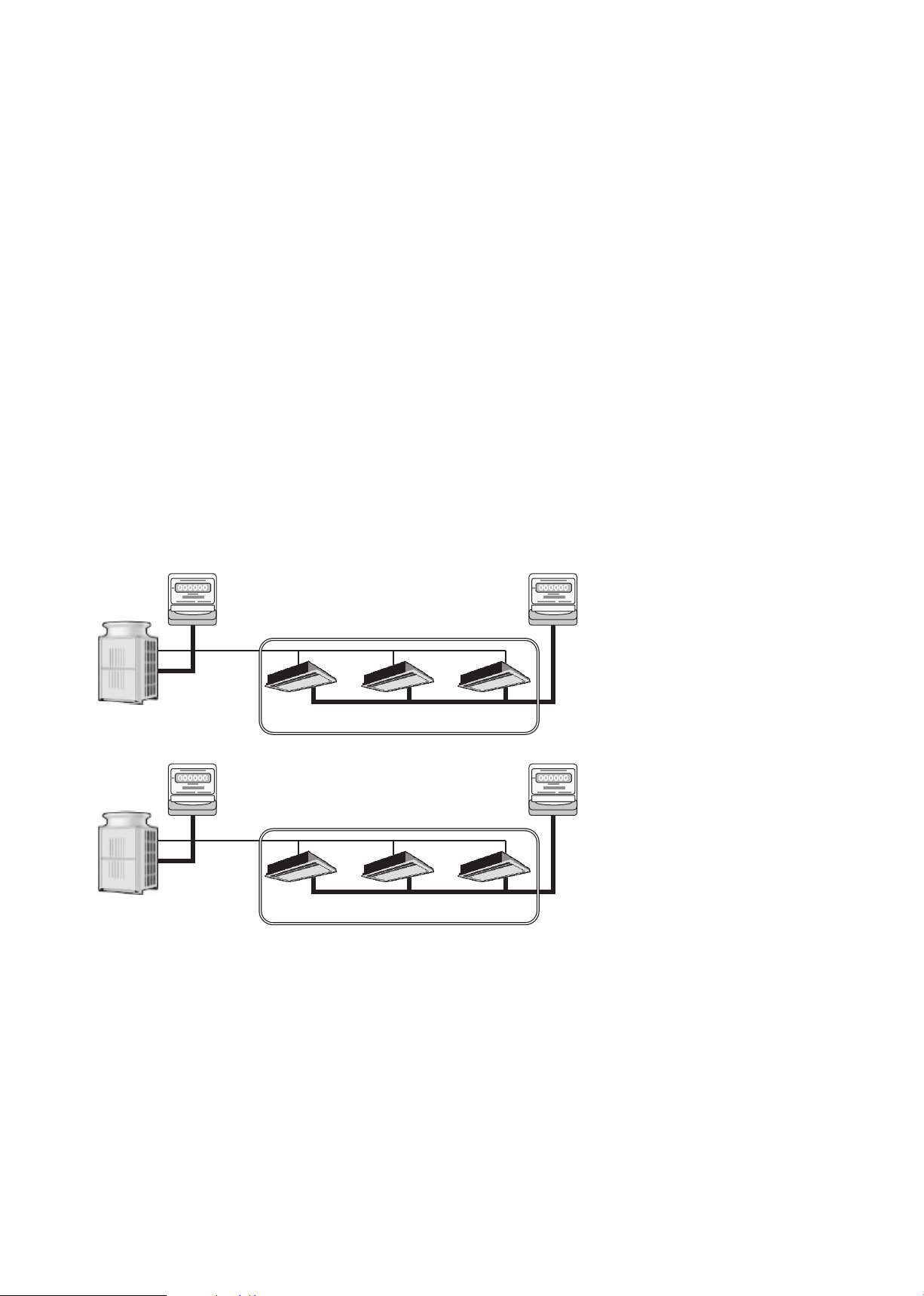
(Example 1) A configuration where the apportioned electricity billing function is not required (where the outdoor
units are each used by just one tenant)
Electricity meter
1-1
Electricity meter
2-1
Outdoor unit A
Outdoor unit B
M-NET
Electricity meter
1-2
M-NET
Tenant A = [Electricity meter 1-1] + [Electricity meter 2-1]
Indoor unit
A1
Tenant B = [Electricity meter 1-2] + [Electricity meter 2-2]
Indoor unit
B1
Indoor unit
A2
Indoor unit
B2
Indoor unit
A3
Indoor unit
B3
Electricity meter
2-2
WT07442X02
9
Page 10
(Example 2) A configuration where the apportioned electricity billing function is required (when the outdoor units
in the same system are installed to multiple tenants)
Electricity meter
2
AE-200
Electricity meter
1
HUB
LAN
AE-50/EW-50
M-NET
M-NET
Outdoor unit A
Outdoor unit B
M-NET
M-NET
Tenant A
Indoor unit
A1
Tenant D
Indoor unit
B1
Tenant B
Indoor unit
A2
Indoor unit
B2
Tenant C
Indoor unit
A3
Indoor unit
B3
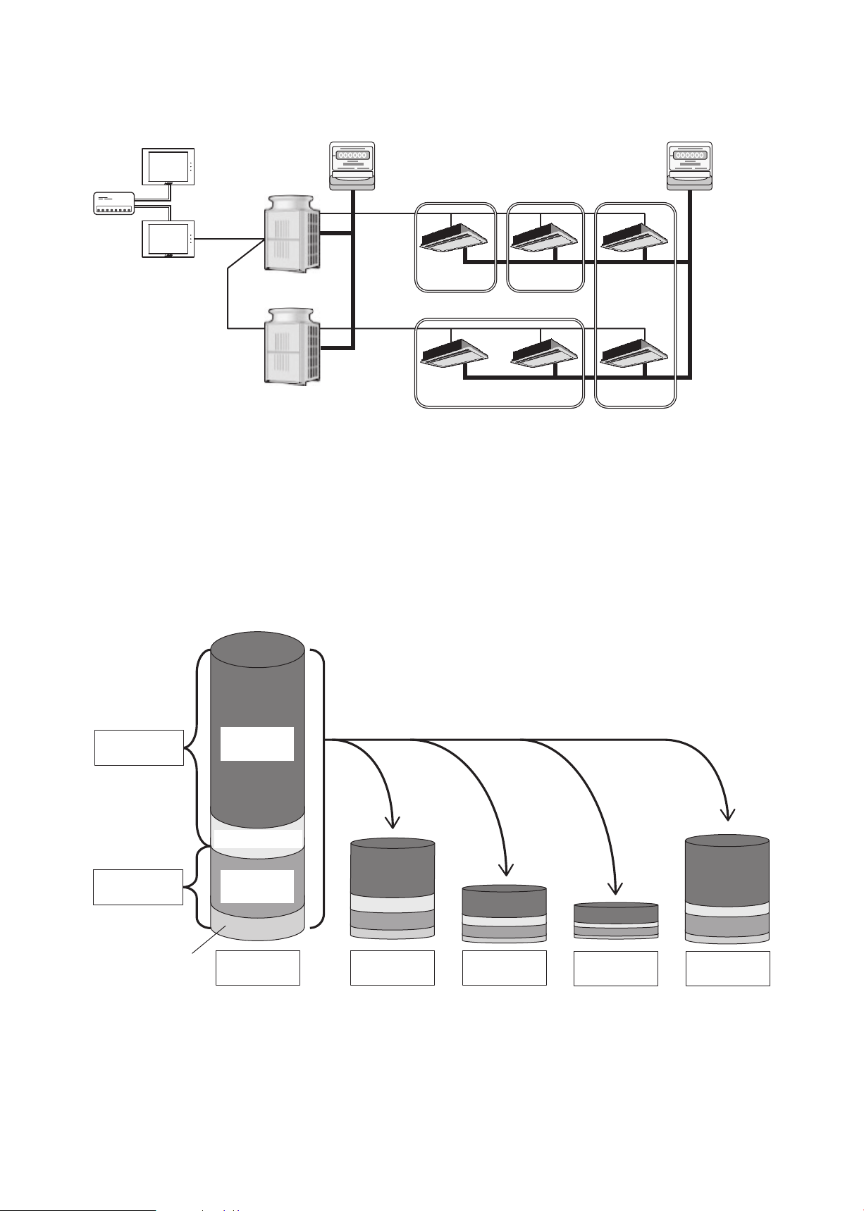
The electric energy used by an air conditioner consists of the electric energy that is consumed by the outdoor
unit and the electric energy that is consumed by the indoor unit. And the outdoor unit electric energy consumption
consists of the operating electric energy plus the standby electric energy. Similarly, the indoor unit electric energy
consumption consists of the operating electric energy plus the standby electric energy.
With the apportioned electricity billing function, the respective amounts of electric energy can be apportioned
based on the operating status and capacity of each tenant.
The example below describes a system where electric energy is metered (with-metering-device method).
(In systems where the electric energy is entered manually (no-metering-device method), standby electric energy
will not be apportioned.)
Outdoor unit
electric energy
consumption
Indoor unit
electric energy
consumption
Indoor unit standby
electric energy
Outdoor unit
operating electric
energy
Outdoor unit standby
electric energy
Indoor unit
operating electric
energy
Total electric energy
for all tenants
consumption by
Apportionment (based on operating status)
Electric energy
tenant A
Electric energy
consumption by
tenant B
Electric energy
consumption by
tenant C
Electric energy
consumption by
tenant D
The apportioned electricity billing function can be implemented either by apportioning in the AE-200 units or
by using the TG-2000A integration software. This manual explains how to use the function by apportioning in
AE-200 units.
If you are using the TG-2000A integrated management software, refer to the TG-2000A Instruction Book.
WT07442X02
10
Page 11
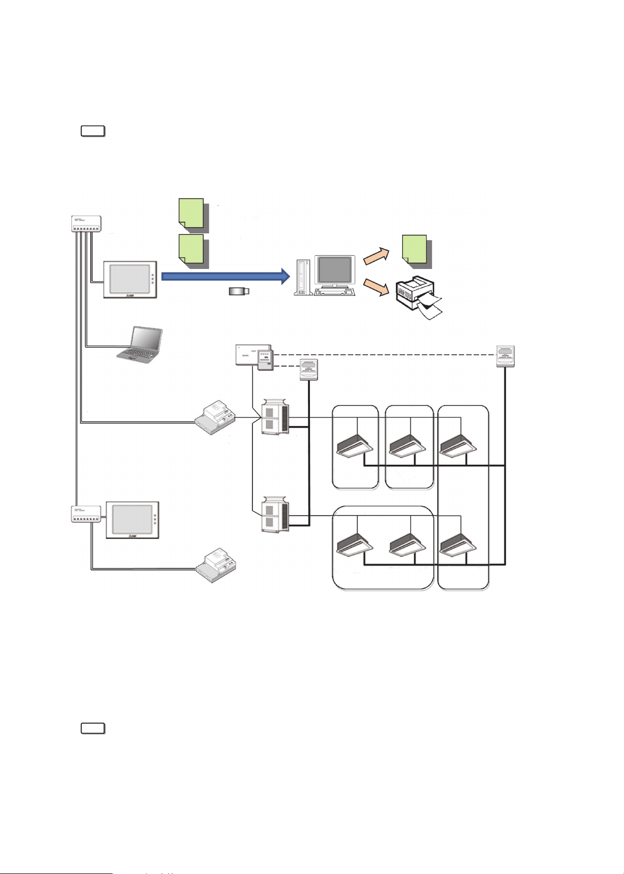
2-2. System overview
The AE-200/AE-50/EW-50 units provide a comprehensive air conditioning management system that supports
web access.
Through the use of the apportioned electricity billing function, they also allow the electric energy used by each
operating air conditioner to be calculated.
Note
• The example below describes a system where electric energy is metered (with-metering-device method).
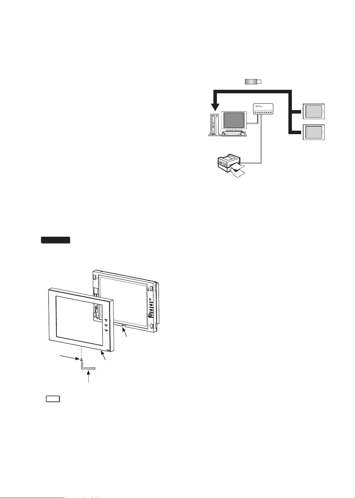
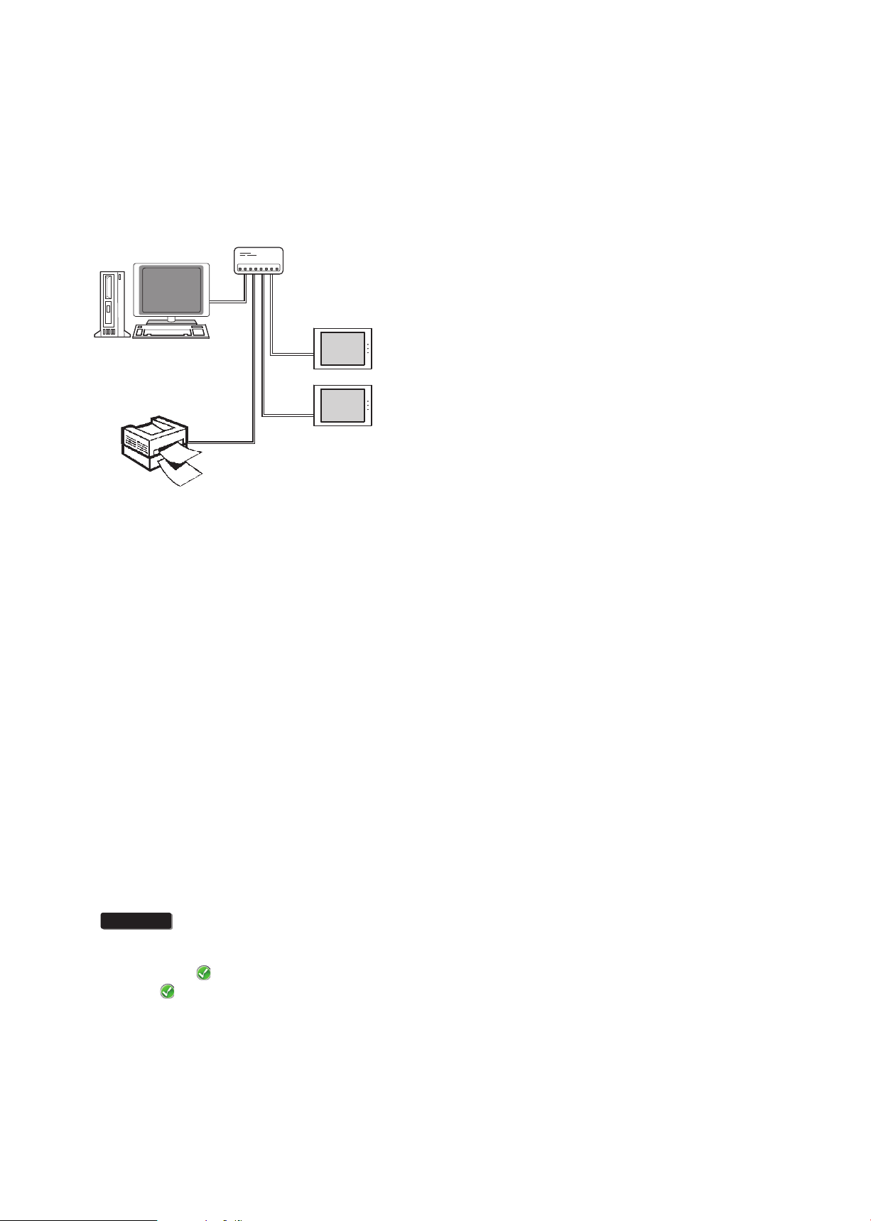
The figure below provides a schematic of the system configuration.
CSV data
(apportioned results)
“Energy management block”
HUB
HUB
LAN
LAN
LAN
AE-200
PC
(Initial Setting Tool)
AE-200
CSV data
(apportioned results)
“Metering device”
USB memory or
LAN communication
connection
AE-50/EW-50
PI controller
M-NET
M-NET
(Charge Calculation Tool)
Outdoor unit A
Outdoor unit B
PC
Pulse input communication
Electricity meter
1-1
Tenant A
Indoor unit
A1
Tenant D
Tenant B
Indoor unit
A2
CSV data
(Charge calculation results)
Printer
(Charge calculation results printout)
Electricity meter
2-1
Tenant C
Indoor unit
A3
LAN
AE-50/EW-50
Apportioned electricity billing function requires the following tools:
• Charge Calculation Tool
This tool is required in order to use the AE-200 CSV data (apportioned results) to output the electricity
charges for each tenant, either as a CSV file or as hard-copy printout.
• Initial Setting Tool
This tool is required to make the settings for the apportioned electricity billing function.
Note
• Charge Calculation Tool can calculate the charges for up to 40 AE-50/EW-50 controllers collectively.
Although the connection destination of Charge Calculation Tool is AE-200, AE-200 units set as [AE-200
(Billing)] or [AE-200 (No M-NET)] on the Initial Setting Tool are not included in this 40 connections.
Refer to section 1-4 “PC requirements” for information on the PC system requirements.
Refer to section 5 “Preparation of the software (installation)” for how to install the software.
Refer to section 6-2-2 “AE-200 unit settings” for how to make AE-200 unit settings.
WT07442X02
11
Indoor unit
B1
Indoor unit
B2
Indoor unit
B3
Page 12
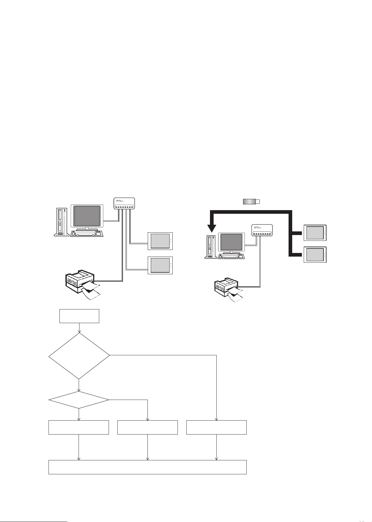
2-3. Selecting the operation method
As shown in the figure below, note that the setting procedure and output method differ depending on the billing
apportionment data collection method and charge calculation method.
Charge calculation method
Closing date calculation (Automatic output)
①
A method where the charge calculation results are automatically output by the PC on the closing date each
month.
* The PC must be running at the time the results are output.
* Results can also be automatically output once a day.
Specified date calculation
②
A method where charges are calculated and output by manually specifying a target period.
* The PC must be started up at the time the results are output.
Billing apportionment data collection method
When the AE-200 and PC are connected via
③
a LAN
(AE-50/EW-50 units are omitted in the figure
below.)
HUB
LAN
PC
LAN
Printer
Operation method
LAN
AE-200
LAN
AE-200
When the CSV data (apportioned results) are
④
exported from the AE-200 to USB memory
(AE-50/EW-50 units are omitted in the figure
below.)
USB memory
HUB
LAN
PC
LAN
Printer
AE-200
AE-200
WT07442X02
Specified date
calculation or closing
date calculation
(automatic output)?
Specified date calculation
LAN or USB?
LAN
③
Specified date calculation
(LAN)
See section 3-1 “Specified
date calculation (LAN
connection)”.
Closing date calculation (automatic output)
②
USB
④
Specified date calculation
Specify the charge calculation output method
(USB)
See section 3-2 “Specified
date calculation (USB)”.
12
①
Closing date calculation
(automatic output)
See section 3-3 “Closing
date calculation (automatic
output)”.
Page 13
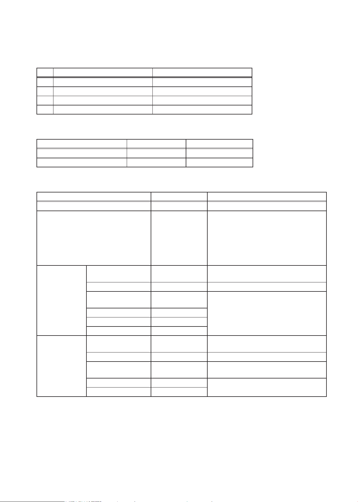
2-4. Function list
Electricity meter
measurement method
*1*2
Systems where electric energy is metered (with-metering-device method):
A system where the amount of electric energy and the charges are calculated by
connecting a PI controller and capturing electric energy pulses
Systems where electric energy is entered manually (no-metering-device method):
A system where the charge rates are calculated without connecting electricity meters
Apportionment method Outdoor unit electric energy apportionment
Operating electric energy (capacity save amount, thermo-ON time, fan operation time)
Standby electric energy (apportioned/not apportioned)
Indoor unit electric energy apportionment
Operating electric energy (apportioned/not apportioned)
Standby electric energy (apportioned/not apportioned)
Charge calculation method
*3*4
Specified date calculation
The charge calculation results for a specified date can be output either as a CSV file or as
hard-copy printout.
Electric energy data from an AE-200 can be acquired either via a LAN connection or using
USB memory.
Closing date (automatic output) calculation
Daily or monthly charge calculation results can be automatically output either as a CSV
file or as hard-copy printout.
Electric energy data from an AE-200 can only be acquired via a LAN connection.
When outputting charge calculation results monthly, either the end of the month or any
date between the 1st and the 28th can be selected as the closing date.
When using closing date calculation, a PC with the Charge Calculation Tool installed must
be running at 5.00 AM on the day after the closing date for monthly calculation, or at 5.00
AM every day for daily calculation.
Standby electric energy
invoicing method
*2
Either to invoice for standby electric energy (invoices to tenants) or to not invoice (left to the
building owner’s discretion) can be selected.
(Refer to section 6-7-1 “Billing function settings” for details.)
Printing/CSV output setting
*7
Systems where electric energy is metered (with-metering-device method)
You can print and/or output CSV files for each energy management block (tenant).
• Apportioned electric energy (total)
• Apportioned electric energy and electricity charges for the respective unit prices (1-5)
• Air conditioning charges
You can print and/or output CSV files for each metering device.
• Measurement value (total)
• Unit (kWh, m3, MJ, (blank))
• Measurement values for the respective unit prices (1-5)
• Charges
Systems where electric energy is entered manually (no-metering-device method)
You can print and/or output CSV files for each energy management block (tenant).
• Indoor unit charge rate
• Outdoor unit charge rate
*5
*6
*1 The AE-200 apportioned electricity billing function does not support the PLC (electric energy counting software) system.
*2 In systems where electric energy is entered manually (no-metering-device method), only charge rates will be calculated. Electric energy
charges cannot be calculated.
The “AE-200ChargeCalc.xlsm” tool, which supports easy calculation of air conditioning charges based on the calculated charge ratio, is
installed together with the Charge Calculation Tool. To use this tool, refer to “Appendix 1. Using the AE-200 Charge Calculation Support
Tool”.
*3 Display and printing is possible for charge calculations up to 62 days previously.
*4 Charges for periods more than 62 days ago can be recalculated by periodically saving CSV files onto USB memory.
*5 Electricity meters are required for each AE-200 system (combination of AE-200 and AE-50/EW-50). (Electric energy will be apportioned
for each AE-200 system.)
*6 29th, 30th or 31st cannot be set as the closing date.
*7 The information displayed for printing and CSV output is different.
Refer to sections 3-5 “Printing the charge calculation results” and 3-6 “Examples of charge calculation results CSV output” for details.
WT07442X02
13
Page 14

2-5. System restrictions
• “Charge” license is required for each AE-200/AE-50/EW-50.
• Combinations of AE-200 and AE-50/EW-50 units are required.
• M-NET of AE-200 for billing function cannot be used.
• Built-in Pulse Input (PI) of AE-200 for billing function cannot be used.
• Electric energy measurement using a PI controller is recommended.
(If AE-50/EW-50 with built-in Pulse Input (PI) is used, pulse input will not be possible when the
AE-50/EW-50 is stopped, during power outages or during software updates. This could result in
discrepancies between the measurements and the actual electric energy used.)
• Ensure that the same software versions are used on AE-200/AE-50/EW-50 units.
• The apportioned electricity billing function (AE-200 Apportion) and apportioned electricity billing function
(TG-2000A Apportion) cannot be used together.
• When the apportioned electricity billing function (AE-200 Apportion) is being used and you intend to use
the TG-2000A integration software, check that the TG-2000A version is 6.60 or later.
• Electric energy pulse input is required for each AE-200 system. You cannot make settings (apportionment
settings) that span multiple AE-200 systems.
2-6. Notes on using the apportioned electricity billing function
• This function is our original electric energy apportionment system that apportions electric energy using
input from electricity meters with a pulse generator function. Rather than directly measuring the electric
energy used by each air conditioner, pulses are input based on the air conditioner usage by determining
the air conditioner operating status from the content of its communication with the indoor and outdoor
units.
To all users (user license agreement)
The information provided here constitutes an agreement between Mitsubishi Electric and the
customer.
If this “apportioned electricity billing function for the AE-200 air conditioning control system” is used,
this agreement assumes that the customer is using the aforementioned system having agreed to the
terms listed below.
• Mitsubishi Electric and its sales companies accept no liability whatsoever for any incidental,
consequential or special damages incurred by the customer, even where the sales company has
received notification of the potential for damages of that kind.
Nor is any liability accepted for any allegations regarding the rights of a third party.
Important
Any individual agreement between the building owner and a tenant regarding the use of this product
should incorporate the parties’ agreement to or accord with the fact that “charges for the use of air
conditioning will be collected in the form of apportioned totals based on the operating status of air
conditioners (including temporary measures to deal with faults)”.
• This is a system for estimating the operating electric energy used for air conditioning. As such it
cannot be used as a proof of transaction.
Also, amounts metered using electricity meters are also counted using pulse conversion and
cannot be used as a proof of transaction.
• This is not a system (or its equivalent) in which the operating electric energy used by each air conditioner
is directly measured at the location where the electricity is supplied.
• Because this is an apportionment method that uses the operating status of air conditioner indoor units,
even where the operating time for indoor units is the same, the amount of operating electric energy used
may differ depending on the model configuration and operating status of the outdoor units.
(The apportioned electric energy may be different when compared with a situation where an electricity
meter is assigned to each air conditioner.)
• Air conditioners still receive current even when stopped, and electric energy is apportioned to idle air
conditioners as standby electric energy.
• While the amounts of electric energy, water and gas used are obtained through pulse conversion,
WT07442X02
14
Page 15

factors such as performance and accuracy are dependent on the metering devices and Mitsubishi
Electric is in no way responsible for such factors.
• If electric power to the AE-200/AE-50/EW-50 and PI controller is interrupted due to a power outage but the
air conditioner is still running, electric energy cannot be apportioned correctly.
• Because the unit price digits for each tenant (energy management block) are rounded off in the charge
calculation process, the figures may differ from the total electric energy charges.
• Because time discrepancies may result in variations in the apportionment processing results, the times
on the AE-200’s LCD should be periodically synchronized. (Even if times have been synchronized on the
AE-50/EW-50, they will be overwritten by the time on the AE-200.)
• Mitsubishi Electric accepts no liability for the incorrect apportionment of electric energy due to problems
such as power outages or equipment faults.
WT07442X02
15
Page 16

3. Basic operations
3-1. Specified date calculation (LAN connection)
This section explains how to calculate the charges for the specified period when the AE-200 is connected to a
PC via a LAN.
The AE-200 must be connected to the PC and printer (for printing) via the LAN.
3-1-1. Preparation of the PC
By connecting the AE-200 to the PC (running the Charge
Calculation Tool) via a LAN, both “Print” and “CSV output” for the
charge calculation results will be enabled.
• Printer setting is required when the output method is set
as “Print”.
Procedures
1. Click [Devices and Printers] in the Start menu.
LAN
PC
(Charge Calculation Tool)
HUB
LAN
AE-200
2. Check that [
] is shown on the printer to be used for
LAN
printing.
If the [ ] is shown on other printer, right-click the printer to
LAN
be used for printing and then click [Set as default printer].
Printer
* The AE-50/EW-50 units are omitted in the figure
above.
3-1-2. Making the settings for the Charge Calculation Tool
Refer to section 5-1 “Installation procedures of the Charge Calculation Tool” for how to install the Charge
Calculation Tool.
Procedures
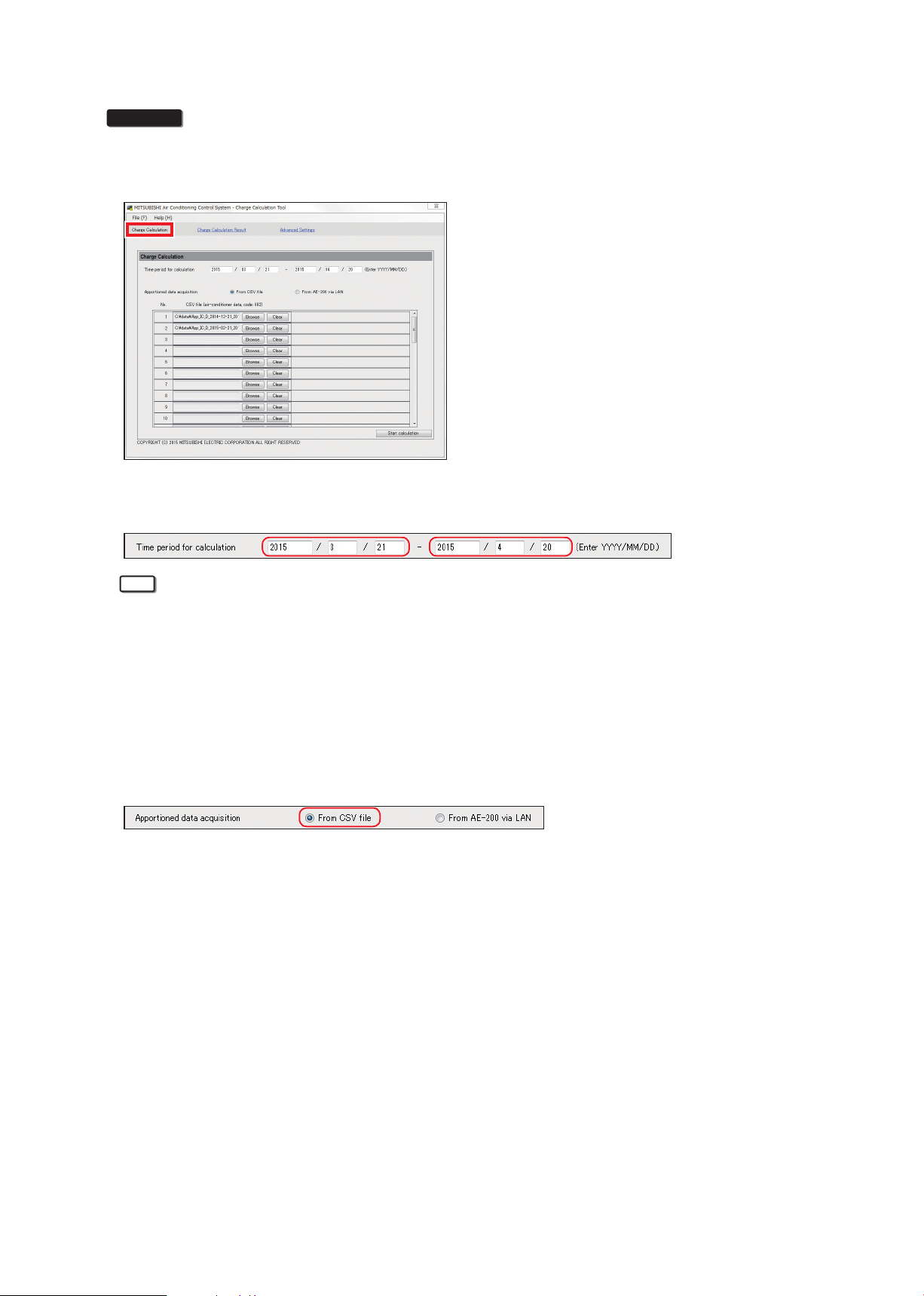
1. Start up the Charge Calculation Tool.
2. Select [Charge Calculation].
AE-200
3. In “Time period for calculation”, enter the start date and end date for the time period for which you want to
calculate the charges in the respective input fields. (Format: YYYY/MM/DD)
WT07442X02
16
Page 17
Note
• Calculations on the Charge Calculation Tool will be output for periods shorter than that covered by the data
stored in the AE-200 (maximum of the preceding 62 days).
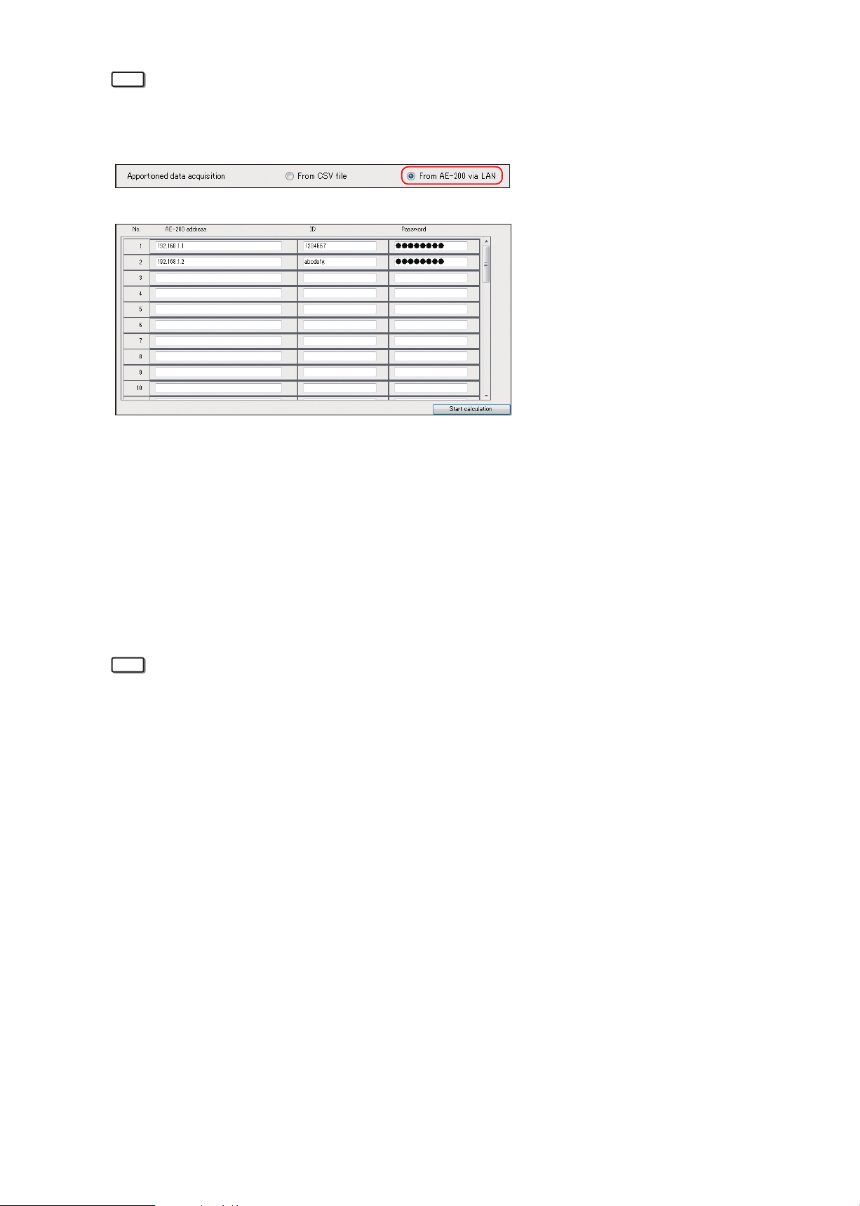
4. In the Basic Settings screen, select [From AE-200 via LAN] as the apportioned data acquisition method.
5. AE-200 address input field
• Enter the IP address of the AE-200.
• If there are multiple AE-200 units, enter the IP addresses of all the AE-200 units.
• AE-50/EW-50 units within the AE-200 system do not need to be registered.
6. ID and password input fields
• Enter the ID and password set for the AE-200 for which you want to calculate charges.
• Enter the ID and password of the building manager for the AE-200.
7. Click [Start calculation].
The charge calculation results will be displayed. (Refer to section 3-4 “Displaying charge calculation
results”.)
Note
• The settings in procedures 4 to 6 will be retained so if no changes are required, you don’t need to make
the settings for the second time onwards.
• The apportioned data can be acquired from the day after the operation start day.
WT07442X02
17
Page 18
3-2. Specified date calculation (USB)
This section explains how to calculate the charges for the specified period when CSV data (the apportioned
results) has been exported from the AE-200 using a USB memory.
3-2-1. Preparation of the PC
You can export the CSV data (apportioned results) from the
AE-200 to a USB memory, calculate the data on a PC (running
the Charge Calculation Tool) and then “Print” and “CSV output”
the charge calculation results.
USB memory
LAN
HUB
AE-200
PC
LAN
Printer
3-2-2. Data acquisition using USB memory
[1] CSV files (apportioned results) in systems where electric energy is metered (with-metering-
device method)
“Energy management block” data and “Metering device” data are required for the charge calculation.
This section explains how to output these data from the AE-200 to USB memory.
Procedures
1. Using an L-shaped driver, remove the hexagon-socket bolt on the underside of the AE-200 unit and then
remove the cover.
AE-200
Hexagon-socket
Note
WT07442X02
AE-200
bolt
L-shaped driver (supplied)
AE-200 cover
• If a separately sold Surface cover with USB port (PAC-YG72CWL-J) is used, you do not need to remove
the AE-200 cover. Open the USB port cover.
18
Page 19
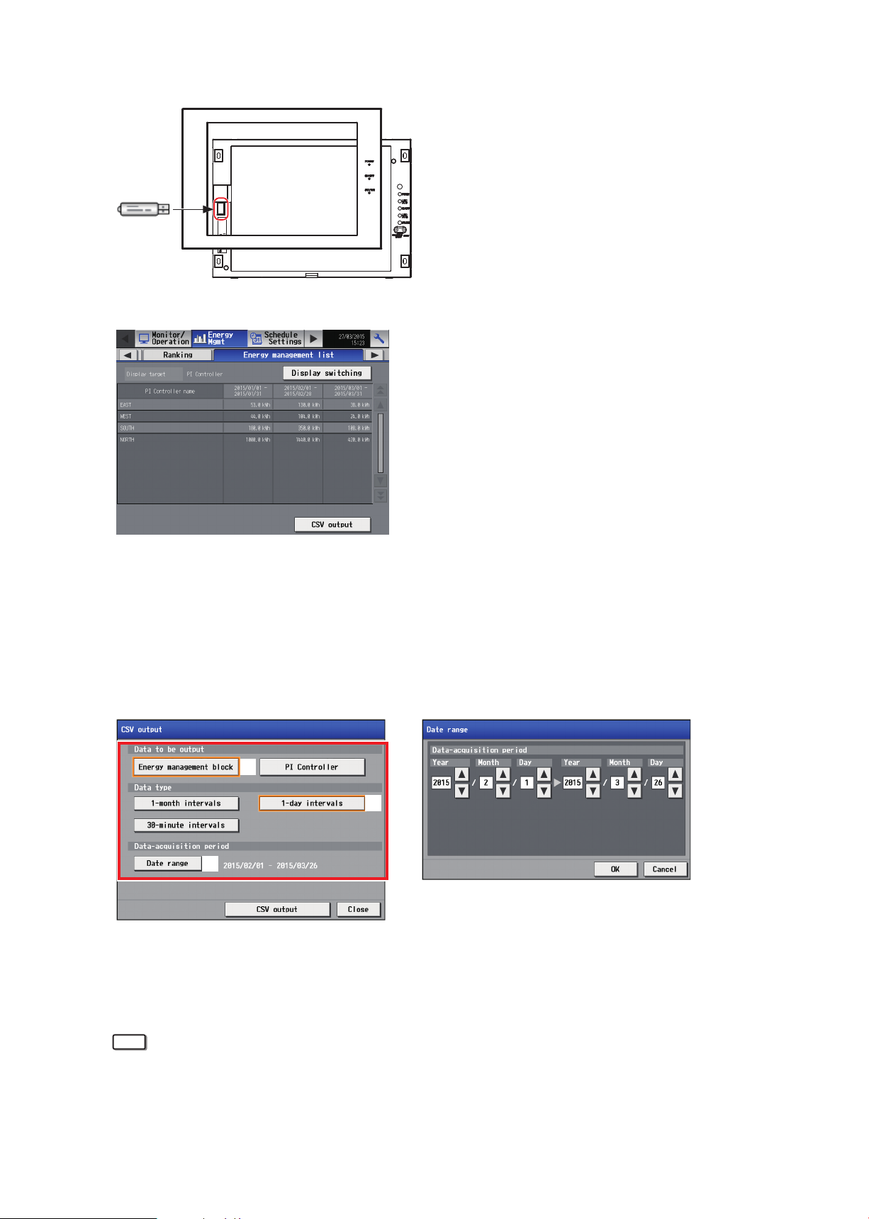
2. Connect a USB memory.
Note
3. Touch [Energy Mgmt] > [Energy management list] on the AE-200’s LCD.
4. Touch [CSV output] to display the CSV output screen and then follow the steps ① to ③.
Data to be output
①
• Select [Energy management block].
Data type
②
• Select [1-day intervals].
Data-acquisition period
③
• Touch [Date range] and select the previous 62 days as the range.
①
②
③
5. Touch [CSV output].
6. When the “The data has been copied.” message appears, touch [OK] to return to the “CSV output” screen.
7. Change the [Energy management block] selected as the data to be output in step 4 ① to [Metering device]
and then touch [CSV output].
• To calculate the charges, be sure to select [1-day intervals].
(Do not select [1-month intervals] or [30-minute intervals].)
• The AE-200 holds the data for the previous 62 days in 1-day intervals.
• The Charge Calculation Tool can calculate charges within the date range of the CSV data (apportioned
WT07442X02
19
Page 20
results) output from the AE-200.
For example, when the CSV data (apportioned results) acquired on the LCD runs from April 1, 2015 to
April 30, 2015, the Charge Calculation Tool cannot calculate charges for CSV data outside that range (e.g.
March 20, 2015 to April 19, 2015). Consequently, it is recommended that you specify the maximum date
range (the previous 62 days) for CSV data (apportioned results) output.
• Refer to section 4-2 “Calculating the charges for 2 months ago or earlier” to calculate charges for data
more than 62 days (2 months) previously.
[2] Systems where the electric energy is entered manually (no-metering-device method)
Even when no electricity meters are connected, the charge rate can still be calculated by using “Energy
management block” data.
Procedures
1.-3. Refer to section [1] “CSV files (apportioned results) in systems where electric energy is metered (withmetering-device method)”.
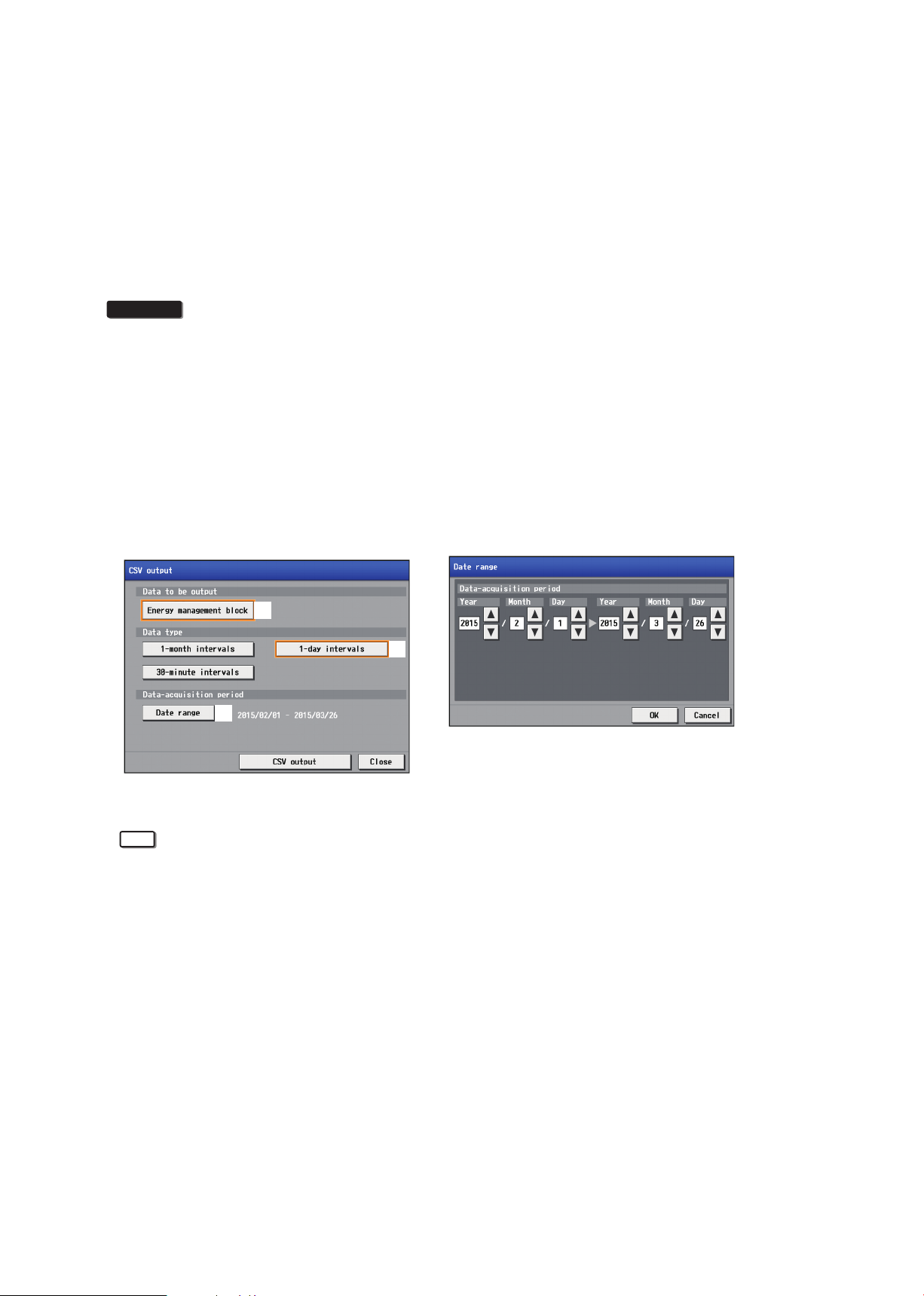
4. Touch [CSV output] to display the CSV output screen and then follow the steps ① to ③.
Data to be output
①
• Select [Energy management block].
Data type
②
• Select [1-day intervals].
Data-acquisition period
③
• Touch [Date range] and select the previous 62 days as the range.
①
②
③
5. Touch [CSV output].
Note
• To calculate the charges, be sure to select [1-day intervals].
(Do not select [1-month intervals] or [30-minute intervals].)
• The AE-200 holds the data for the previous 62 days in 1-day intervals.
• The Charge Calculation Tool can calculate charges within the date range of the CSV data (apportioned
results) output from the AE-200.
For example, when the CSV data (apportioned results) acquired on the LCD runs from April 1, 2015 to
April 30, 2015, the Charge Calculation Tool cannot calculate charges for CSV data outside that range (e.g.
March 20, 2015 to April 19, 2015). Consequently, it is recommended that you specify the maximum date
range (the previous 62 days) for CSV data (apportioned results) output.
• Refer to section 4-2 “Calculating the charges for 2 months ago or earlier” to calculate charges for data
more than 62 days (2 months) previously.
WT07442X02
20
Page 21
3-2-3. Making the settings for the Charge Calculation Tool
Refer to section 5-1 “Installation procedures of the Charge Calculation Tool” for how to install the Charge
Calculation Tool.
[1] Systems where electric energy is metered (with-metering-device method)
Procedures
1. Start up the Charge Calculation Tool.
2. Select [Charge Calculation].
Displayed when the “Metering device connection” setting
is “Connected”.
Note
• Refer to section 4-1-2 “Charge Calculation Tool settings” for “Metering device connection” settings.
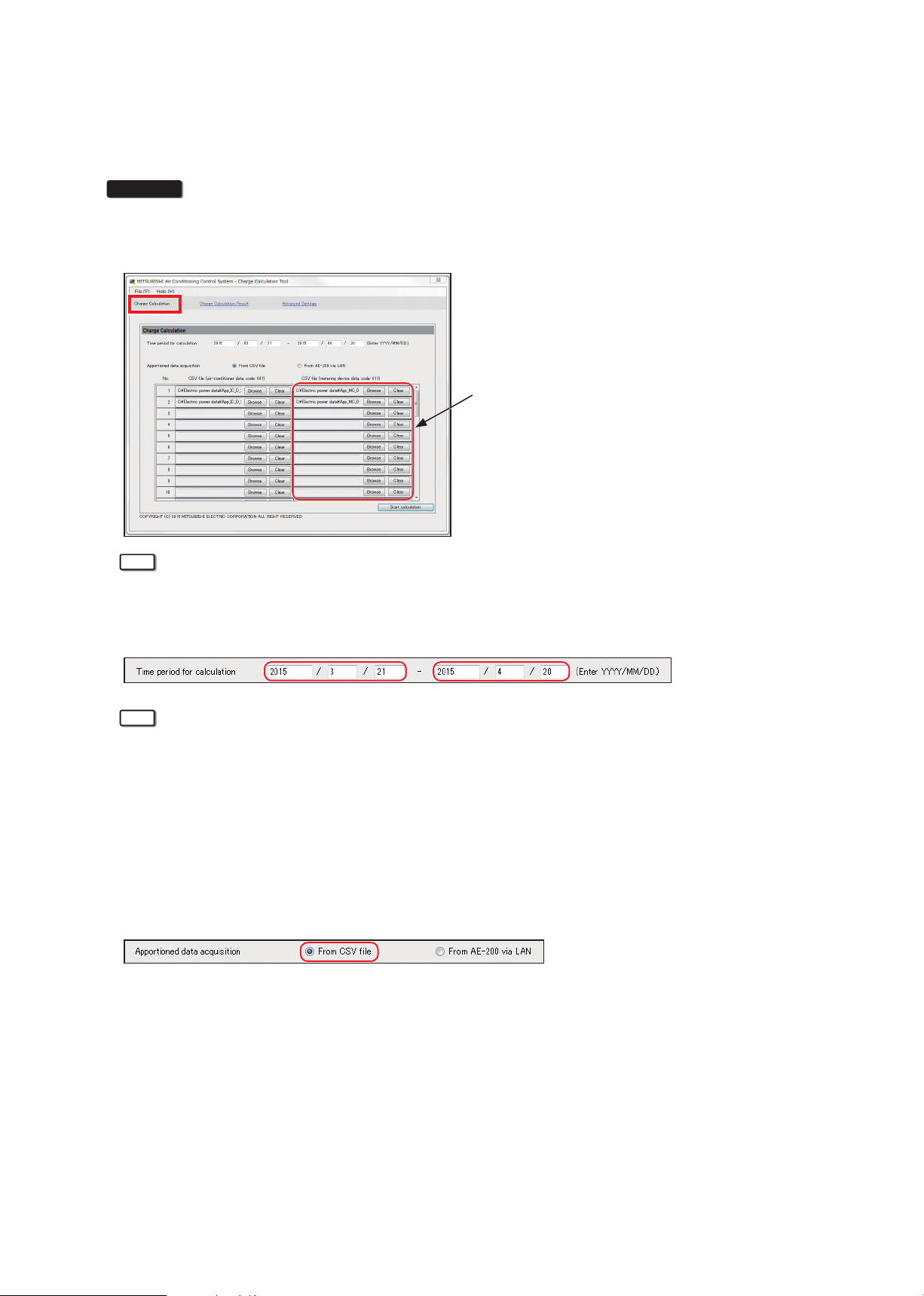
3. In “Time period for calculation”, enter the start date and end date for the time period for which you want to
calculate the charges in the respective input fields. (Format: YYYY/MM/DD)
Note
• The Charge Calculation Tool can calculate charges within the date range of the CSV data (apportioned
results) output from the AE-200.
For example, if the CSV data (apportioned results) acquired on the LCD runs from April 1, 2015 to April 30,
2015, the Charge Calculation Tool cannot calculate charges for CSV data outside that range (e.g. March
20, 2015 to April 19, 2015). Consequently, it is recommended that you specify the maximum date range (the
previous 62 days) for CSV data (apportioned results) output.
• Refer to section 4-2 “Calculating the charges for 2 months ago or earlier” to calculate charges for data
more than 62 days (2 months) previously.
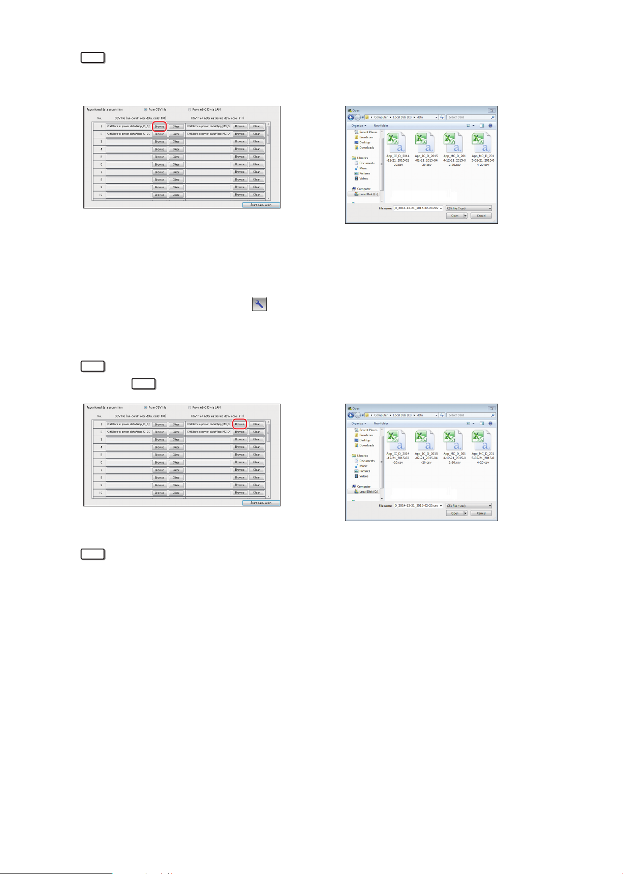
4. Select [From CSV file] as the apportioned data acquisition method in the charge calculation screen.
5. Click [Browse] for the CSV file (air-conditioner data), select the “Energy management block” data file for the
CSV data (apportioned results) acquired from the AE-200 and then click [Open].
WT07442X02
• The file names for CSV data (apportioned results) are as shown below.
■Energy management block
• 1-day intervals: “App”_“IC”_D_[start year]-[start month]-[start day]_[end year]-[end month]-[end day].csv
■Metering device
• 1-day intervals: “App”_“MC”_D_[start year]-[start month]-[start day]_[end year]-[end month]-[end day].csv
Example: For data at 1-day intervals with a target period of March 1, 2015 to April 30, 2015
Energy management block data: App_IC_D_2015-03-01_2015-04-30.csv
Metering device data: App_MC_D_2015-03-01_2015-04-30.csv
21
Page 22
Note
• In the file name, “IC” denotes energy management blocks, “MC” denotes a PI controller, and “D” denotes
data at 1-day intervals.
Example of CSV file (air-conditioner data) selection
(Output CSV file [App_IC_D_2014-12-21_2015-02-20.csv])
• For CSV data (apportioned results), the \(AE-200 serial number)\“ApportionData”\ folder will be created
in the root folder of the USB memory and CSV file will be saved in this folder. Save backup copies of this
folder on the PC.
To check the serial number, touch [ ] in the top-right corner of the LCD. The serial number will be
displayed in the bottom-left corner of the login window.
6. Click [Browse] for the CSV file (metering device data), select the “Metering device” data file for the CSV data
(apportioned results) acquired from the AE-200 and then click [Open].
Note
• Refer to
Note
Note
in procedure 5 for information on the USB memory save destination and the file names.
Example of CSV file (metering device data) selection
(Output CSV file [App_IC_D_2014-12-21_2015-02-20.csv])
• Register one “Energy management block (tenant)” data file and one “Metering device” data file for each
AE-200 unit.
• For each No., register the “Energy management block (tenant)” file and “Metering device” file output by the
same AE-200.
• If there are two AE-200 units, register the two files in the order in which they are output.
• Do not register multiple CSV files output from the same AE-200. If multiple files are registered, charges
may be calculated higher.
• If there are multiple AE-200 units, the charges will be output in order of registration No.
7. Click [Start calculation].
The charge calculation results will be displayed. (Refer to section 3-4 “Displaying charge calculation
results”.)
WT07442X02
22
Page 23
[2] Systems where electric energy is entered manually (no-metering-device method)
Procedures
1. Start up the Charge Calculation Tool.
2. Select [Charge Calculation].
3. In “Time period for calculation”, enter the start date and end date for the time period for which you want to
calculate the charges in the respective input fields. (Format: YYYY/MM/DD)
Note
• The Charge Calculation Tool can calculate charges within the date range of the CSV data (apportioned
results) output from the AE-200.
For example, if the CSV data (apportioned results) acquired on the LCD runs from April 1, 2015 to April 30,
2015, the Charge Calculation Tool cannot calculate charges for CSV data outside that range (e.g. March
20, 2015 to April 19, 2015). Consequently, it is recommended that you specify the maximum date range (the
previous 62 days) for CSV data (apportioned results) output.
• Refer to section 4-2 “Calculating the charges for 2 months ago or earlier” to calculate charges for data
more than 62 days (2 months) previously.
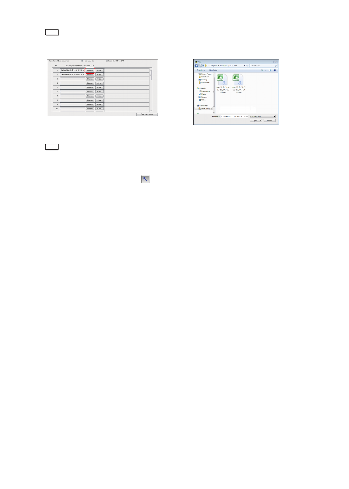
4. Select [From CSV file] as the apportioned data acquisition method in the charge calculation screen.
5. Click [Browse] for the CSV file (air-conditioner data), select the “Energy management block” data file for the
CSV data (apportioned results) acquired from the AE-200 and then click [Open].
• The file names for CSV data (apportioned results) are as shown below.
■Energy management block
• 1-day intervals data: “App”_“IC”_D_[start year]-[start month]-[start day]_[end year]-[end month]-[end day].
csv
Example: For data at 1-day intervals with a target period of March 1, 2015 to April 30, 2015
Energy management block data: App_IC_D_2015-03-01_2015-04-30.csv
WT07442X02
23
Page 24
Note
• In the file name, “IC” denotes energy management blocks, “MC” denotes a PI controller, and “D” denotes
data at 1-day intervals.
Example of CSV file (air-conditioner data) selection
(Output CSV file [App_IC_D_2014-12-21_2015-02-20.csv])
Note
• For CSV data (apportioned results), the \(AE-200 serial number)\“ApportionData”\ folder will be created
in the root folder of the USB memory and CSV file will be saved in this folder. Save backup copies of this
folder on the PC.
To check the serial number, touch [ ] in the top right of the LCD. The serial number will be displayed in
the bottom left of the login window.
• Register one “Energy management block (tenant)” data file for each AE-200 unit.
• If there are two AE-200 units, register the two files in the order in which they are output.
• Do not register multiple CSV files output from the same AE-200. If multiple files are registered, the charge
rates may not be calculated correctly.
• If there are multiple AE-200 units, the charge rates will be calculated in order of registration No.
6. Click [Start calculation].
The charge rates will be displayed. (Refer to section 3-4 “Displaying charge calculation results”.)
WT07442X02
24
Page 25
3-3. Closing date calculation (automatic output)
This section explains the closing date calculation (automatic output) when the AE-200 is connected to a PC via a
LAN.
The AE-200 must be connected to the PC and printer (for printing) via the LAN.
3-3-1. Preparation of the PC
By connecting the AE-200 to the PC (running the Charge Calculation Tool) via a LAN, both “Print” and “CSV
output” for the charge calculation results will be enabled.
To print out the data, a printer must be connected via the LAN.
HUB
LAN
PC
LAN
Printer
* The AE-50/EW-50 units are omitted in the figure above.
LAN
AE-200
LAN
AE-200
Closing date calculation (automatic output) is only available when connected via a LAN.
The data will be output automatically at 5:00 AM on the day after the “Closing date” set on the Charge
Calculation Tool. If output is set to “Daily”, the previous day’s data will be automatically output at 5:00 AM
each day.
You can specify “Print”, “CSV output” or both as the output options for the charge calculation results.
Prepare a PC and printer that meet the following criteria:
• The PC must be turned on when the data is automatically output (5:00 AM)
• If login settings are set for the PC, a user must be in logged-in status when the data is automatically output
• The PC must not be in standby or sleep mode when the data is automatically output
• The Charge Calculation Tool must not be launched manually when the data is automatically output
* The tool starts up automatically.
• The AE-200 must be connected to the PC via a LAN
• If “Print” is selected as the output method, the printer must be turned on when the data is automatically
output (5:00 AM)
• If “Print” is selected as the output method, there must be “Default printer” setting in the Windows printer
settings.*
* The procedures for setting the printer as the default printer is shown below.
Procedures
1. Click [Devices and Printers] in the Start menu.
2. Check that [
] is shown on the printer to be used for printing.
If the [ ] is shown on other printer, right-click the printer to be used for printing and then click [Set as
default printer].
WT07442X02
25
Page 26
3-3-2. Making the settings for the Charge Calculation Tool
Refer to section 5-1 “Installation procedures of the Charge Calculation Tool” for how to install the Charge
Calculation Tool.
Procedures
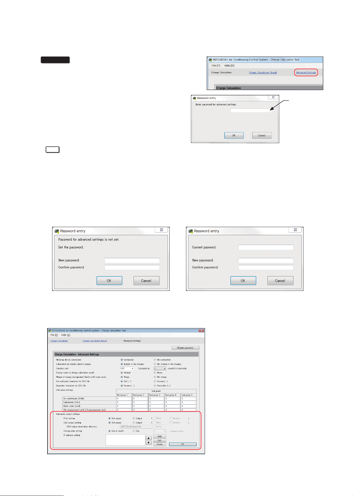
1. Start up the Charge Calculation Tool.
2. Select [Advanced Settings].
3. Enter the password.
Note
Enter the
password.
• The “Password first-input window” will appear for the initial setting. Enter the password you wish to use
twice. (Make a note of your password so as not to forget it.)
• If you forget your password, contact your dealer.
• To change your password, click [Change password] on the top right of the Advanced Settings screen.
When the “Password change window” opens, enter your current password and then enter the new
password.
• Your password must consist of at least 8 characters and no more than 20 characters.
(The following characters cannot be used: <, >, &, “, or ‘)
Password first-input window Password change window
4. Make the “Automatic output settings” in the Advanced Settings screen.
Refer to section 3-3-3 “Settings on the Charge Calculation Tool” for details on how to make the settings.
5. Click [OK] (the changes will be applied).
WT07442X02
26
Page 27
3-3-3. Settings on the Charge Calculation Tool
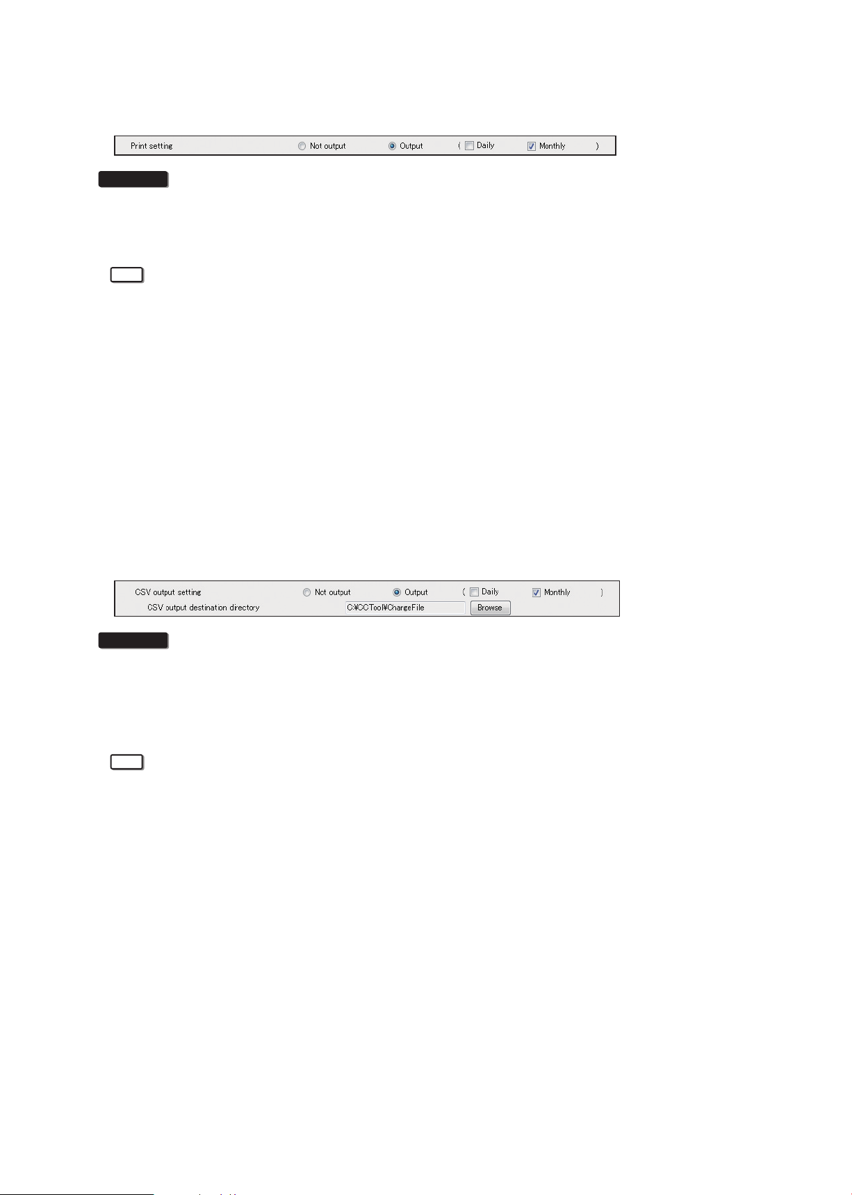
(1) Print setting
Procedures
1. Select [Output] in “Print setting”.
2. Check the [Daily] or [Monthly] checkbox or both.
(In the example shown above, [Monthly] is selected as the print setting.)
Note
Set the PC and printer to meet the following operating environment.
• Settings are required to carry out the closing date calculation (automatic output).
• The PC must be turned on when the data is automatically output (5:00 AM)
• If login settings are specified for the PC, a user must be in logged-in status when the data is automatically
output
• The PC must not be in standby or sleep mode when the data is automatically output
• The Charge Calculation Tool must not be launched manually when the data is automatically output
• The AE-200 must be connected to the PC via a LAN
• If “Print” is selected as the output method, the printer must be turned on when the data is automatically
output (5:00 AM)
• If “Print” is selected as the output method, there must be “Default printer” setting in the Windows printer
settings.
(2) CSV output setting
Procedures
1. To save the calculation results as a file, select [Output] in “CSV output setting”.
2. Check the [Daily] or [Monthly] checkbox or both.
3. Click [Browse] in “CSV output destination directory” and select your intended file output destination folder.
(In the example shown above, [Monthly] is selected as the print setting.)
Note
• Settings are required to carry out the closing date calculation (automatic output).
• When [Output] is selected in “CSV output setting”, the Charge Calculation Tool starts up at the time when
the data is automatically output (5:00 AM).
• CSV files will be output to a directory with the closing date (\“year”\“month”\) added to the specified CSV
output destination directory.
Example: When CSV files are output at 5:00 AM on February 1, 2015 (the day after the closing date), the
dates on the output files will be the closing date year and month (day).
→ The directory will be “C: \CCTool\ChargeFile\2015\01\”
• The file names for charge calculation results for “Each energy management block (tenant)” will be as
follows:
Daily: “[year][month][day]B.csv” (e.g.: A file output on February 1, 2015 will be output as “20150131B.
csv”.)
Monthly: “[year][month]B.csv” (e.g.: A file output on February 1, 2015 will be output as “201501B.csv”.)
• The file names for charge calculation results for “Each metering device” will be as follows:
Daily: “[year][month][day]W.csv” (e.g.: A file output on February 1, 2015 will be output as “20150131W.
csv”.)
Monthly: “[year][month]W.csv” (e.g.: A file output on February 1, 2015 will be output as “201501W.csv”.)
WT07442X02
27
Page 28
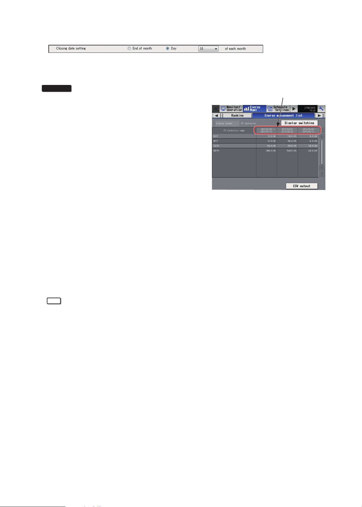
(3) Closing date setting (automatic output)
Carry out the following procedures to set the date for “Monthly” automatic output in “Closing date setting”.
In this setting, you can set the closing date to output the charge calculation results.
Make sure that this date matches the closing date set on the “Energy management list” on the AE-200.
Procedures
1. Touch [Energy Mgmt] > [Energy management list] on the
AE-200’s LCD, and check the display period of electric
energy.
2. Set the closing date based on the display period of
electric energy.
Example 1. If the period is “2015/03/01-2015/03/31”,
the final day is the last day of the month,
so you should select “End of month” as the
closing date.
Example 2. If the period is “2015/03/11-2015/04/10”,
you should select “Day (10) of each month”
as the closing date.
• When the end of the month is selected
When the end of the month is selected, the charge calculation results for each month will be output on the
1st of the following month.
For example, the data output at 5:00 AM on February 1, 2015 will be the charge calculation results for
January 1-31, 2015.
• If another day of each month is selected
If you select “Monthly”, click the pull-down menu for “Day” and select a date between 1 and 28 as the
desired output date.
Once you select a date, the charge calculation results for the month preceding the selected date will be
output on the day after the selected date.
For example, if you select monthly output on the 25th on April 1, 2015, the next data output will be at 5:00
AM on April 26, 2015, and the charge calculation results for the period from March 26, 2015 to April 25,
2015 will be output.
Note
• Settings are required to carry out the closing date calculation (automatic output).
• If [Output] is selected in both printing and CSV output settings, you cannot set separate closing dates for
printing and CSV output.
• 29th, 30th or 31st cannot be set as the closing date for every month.
• There are two types of “Closing date”: Calculation on the closing date (automatic output) <set on the
Charge Calculation Tool>; or energy management list (monthly display) <set on Initial Setting Tool> shown
on the AE-200’s LCD.
• The “Energy management list” is displayed as of the day after the closing date.
Display period of electric energy
WT07442X02
28
Page 29
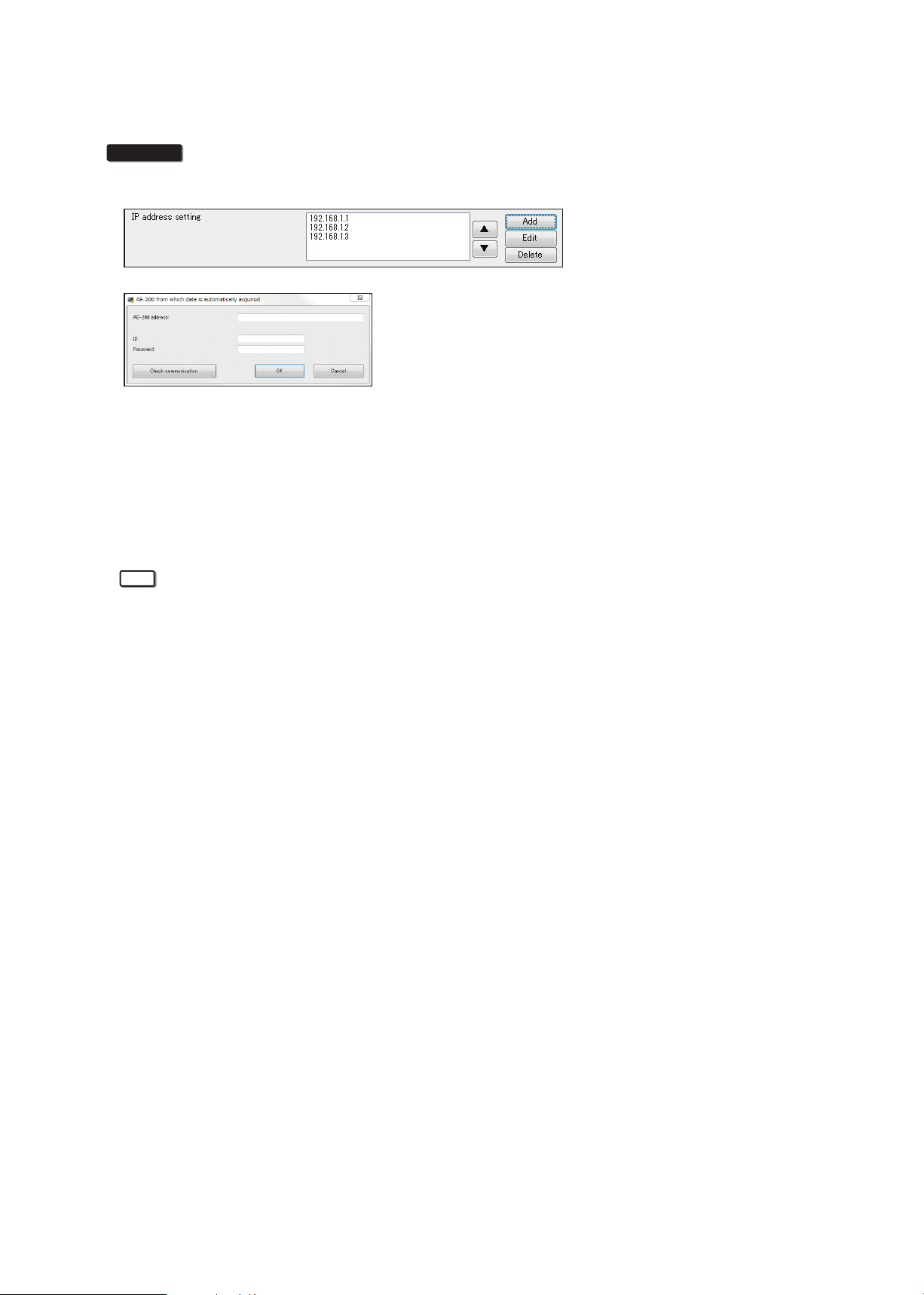
(4) IP address setting
This section explains how to set the IP address used to automatically acquire “Energy management” data
and “Metering device” data from the AE-200.
Procedures
1. Click [Add] in the IP address setting.
2. When the “AE-200 from which data is automatically acquired” screen appears, enter the IP address of the
AE-200 for which charges will be calculated along with the building manager ID and password.
3. Click [Check communication] and check that the tool can communicate with the AE-200. When the
communication is successful, a message “Communication succeeded” will appear.
4. Click [OK] and check that the address has been added in the IP address settings column.
5. If there are multiple AE-200 units for which charges are to be calculated, repeat procedures 1 to 4 above to
register all the AE-200 units for which charge calculation is required.
Note
• Settings are required to carry out the closing date calculation (automatic output).
• When [Do not merge] is selected in “Merger of energy management blocks with same name” in the Charge
Calculation Tool’s [Advanced Settings], units will be displayed in the “AE-200 No.X + energy management
block name” format to distinguish the energy management block names.
(Here, the “No.” for an AE-200 is its number in this sequence of IP address settings, starting from No.1.
You can change the order by selecting the IP address and then clicking the [▲] or [▼] button.)
(Refer to section 4-1-2 “Charge Calculation Tool settings”.)
(Example: When the name of the energy management block connected to AE-200 No.1 is “1F tenant”,
“AE-200 No.1 1F tenant” will be displayed.)
• Even when “Merge” is selected, the metering device names in the charge calculation results for each
metering device will not be merged.
• The charge calculation results for each metering device will be displayed in the “AE-200 No.X + metering
device name” format regardless of the setting for merging energy management blocks with the same
name.
• To change the settings, select an IP address and click [Edit].
WT07442X02
29
Page 30
3-4. Displaying charge calculation results
After completing 3-2-3 “Making the settings for the Charge Calculation Tool”, click [Start calculation] in the charge
calculation screen to display the charge calculation results screen.
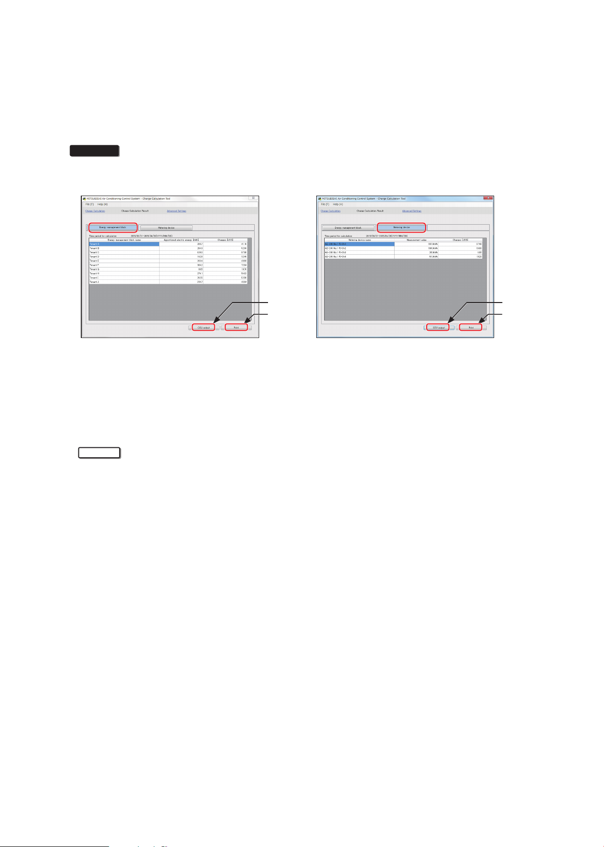
3-4-1. Systems where electric energy is metered (with-metering-device method)
In systems where electric energy is metered (with-metering-device method), the charge calculation results will be
displayed both for each energy management block and for each metering device.
Procedures
1. Click [Energy management block] or [Metering device].
When [Energy management block] is selected When [Metering device] is selected
CSV output
Print
CSV output
Print
2. Click [Print] or [CSV output].
• For printed output
To print out the charge calculation results, click [Print].
The results will be printed out on the printer set as the “Default printer”.
• For CSV output
To output the charge calculation results as a CSV file, click [CSV output].
When the output destination selection dialog box appears, save the file under a name of your choice.
Important
• When you printed out the results, it is recommended that you also use CSV output to make a backup copy
of the calculation results.
WT07442X02
30
Page 31

3-4-2. Systems where electric energy is entered manually (no-metering-device method)
In systems where electric energy is entered manually (no-metering-device method), the charge rates will be
displayed for each energy management block.
CSV output
Print
Procedures
1. Click [Print] or [CSV output].
• For printed output
To print out the charge calculation results, click [Print].
The results will be printed out on the printer set as the “Default printer”.
• For CSV output
To output the charge calculation results as a CSV file, click [CSV output].
When the output destination selection dialog box appears, save the file under a name of your choice.
Important
• When you printed out the results, it is recommended that you also use CSV output to make a backup copy
of the charge rates.
WT07442X02
31
Page 32

3-5. Printing the charge calculation results
㼑㼇
㻜㻤
㻜㻥
㻜㻝
㻜㻞
㻜㻞
㻜㻟
3-5-1. Systems where electric energy is metered (with-metering-device method)
In systems where electric energy is metered (with-metering-device method), the charge calculation results will be
printed out both for each energy management block and for each metering device.
[1] Example of printed results for each energy management block
(Display order of charge calculation result: Number; Merger of energy management blocks with same name: Merge)
[2] Example of printed results for each metering device
(Display order of charge calculation result: Number)
㻭㼕㼞㻌㼏㼛㼚㼐㼕㼠㼕㼛㼚㼕㼚㼓㻌㼏㼔㼍㼞㼓㼑㻌㻙㻌㻹㼑㼠㼑㼞㼕㼚㼓㻌㼐㼑㼢㼕㼏㼑㻌㻔㼎㼥㻌㼡㼚㼕㼠㻌㼜㼞㼕㼏㼑㻕
㻯㼍㼘㼏㼡㼘㼍㼠㼕㼛㼚㻌㼜㼑㼞㼕㼛㼐㻦㻞㻜㻝㻡㻛㻜㻠㻛㻜㻝㻙㻞㻜㻝㻡㻛㻜㻠㻛㻟㻝
㻹㼑㼠㼑㼞㼕㼚㼓㻌㼐㼑㼢㼕㼏㼑㻌㼚㼍㼙㼑 㻹㼑㼟㼡㼞㼑㼙㼑㼚㼠㻌㼢㼍㼘㼡㼑㼁㼚㼕㼠㻵㼠㼑㼙㼀㼛㼠㼍㼘㻌㼍㼕㼞㻌㼏㼛㼚㼐㼕㼠㼕㼛㼚㼕㼚㼓㻌㼏㼔㼍㼞㼓㼑
㻭㻱㻙㻞㻜㻜㻌㻺㼛㻚㻝 㻠㻠㻚㻜㼗㼃㼔 㼁㼚㼕㼠㻌㼜㼞㼕㼏㼑㻌㻝㻠㻠㻚
㻻㼡㼠㼐㼛㼛㼞㻌㼡㼚㼕㼠㻌㻝䡚㻠㻲 㼁㼚㼕㼠㻌㼜㼞㼕㼏㼑㻌㻞
㻭㻱㻙㻞㻜㻜㻌㻺㼛㻚㻝 㻠㻥㻚㻜㼗㼃㼔 㼁㼚㼕㼠㻌㼜㼞㼕㼏㼑㻌㻝㻠㻥㻚
㻻㼡㼠㼐㼛㼛㼞㻌㼡㼚㼕㼠㻌㻡䡚㻤㻲 㼁㼚㼕㼠㻌㼜㼞㼕㼏㼑㻌㻞
㻭㻱㻙㻞㻜㻜㻌㻺㼛㻚㻝 㻡㻝㻚㻜㼗㼃㼔 㼁㼚㼕㼠㻌㼜㼞㼕㼏㼑㻌㻝㻡㻝㻚
㻻㼡㼠㼐㼛㼛㼞㻌㼡㼚㼕㼠㻌㻥䡚㻝㻞㻲 㼁㼚㼕㼠㻌㼜㼞㼕㼏㼑㻌㻞
㻭㻱㻙㻞㻜㻜㻌㻺㼛㻚㻝 㻝㻝㻚㻜㼗㼃㼔 㼁㼚㼕㼠㻌㼜㼞㼕㼏㼑㻌㻝㻝㻝㻚
㻵㼚㼐㼛㼛㼞㻌㼡㼚㼕㼠㻌㻝䡚㻠㻲 㼁㼚㼕㼠㻌㼜㼞㼕㼏㼑㻌㻞
㻭㻱㻙㻞㻜㻜㻌㻺㼛㻚㻝 㻝㻟㻚㻜㼗㼃㼔 㼁㼚㼕㼠㻌㼜㼞㼕㼏㼑㻌㻝㻝㻟㻚
㻵㼚㼐㼛㼛㼞㻌㼡㼚㼕㼠㻌㻡䡚㻤㻲 㼁㼚㼕㼠㻌㼜㼞㼕㼏㼑㻌㻞
㻭㻱㻙㻞㻜㻜㻌㻺㼛㻚㻝 㻝㻡㻚㻜㼗㼃㼔 㼁㼚㼕㼠㻌㼜㼞㼕㼏㼑㻌㻝㻝㻡㻚
㻵㼚㼐㼛㼛㼞㻌㼡㼚㼕㼠㻌㻥䡚㻝㻞㻲 㼁㼚㼕㼠㻌㼜㼞㼕㼏㼑㻌㻞
㼁㼚㼕㼠㻌㼜㼞㼕㼏
㼁㼚㼕㼠㻌㼜㼞㼕㼏㼑㻌㻟
㼁㼚㼕㼠㻌㼜㼞㼕㼏㼑㻌㻠
㼁㼚㼕㼠㻌㼜㼞㼕㼏㼑㻌㻡
㼁㼚㼕㼠㻌㼜㼞㼕㼏㼑㻌㻟
㼁㼚㼕㼠㻌㼜㼞㼕㼏㼑㻌㻠
㼁㼚㼕㼠㻌㼜㼞㼕㼏㼑㻌㻡
㼁㼚㼕㼠㻌㼜㼞㼕㼏㼑㻌㻟
㼁㼚㼕㼠㻌㼜㼞㼕㼏㼑㻌㻠
㼁㼚㼕㼠㻌㼜㼞㼕㼏㼑㻌㻡
㼁㼚㼕㼠㻌㼜㼞㼕㼏㼑㻌㻟
㼁㼚㼕㼠㻌㼜㼞㼕㼏㼑㻌㻠
㼁㼚㼕㼠㻌㼜㼞㼕㼏㼑㻌㻡
㼁㼚㼕㼠㻌㼜㼞㼕㼏㼑㻌㻟
㼁㼚㼕㼠㻌㼜㼞㼕㼏㼑㻌㻠
㼁㼚㼕㼠㻌㼜㼞㼕㼏㼑㻌㻡
㼁㼚㼕㼠㻌㼜㼞㼕㼏㼑㻌㻟
㼁㼚㼕㼠㻌㼜㼞㼕㼏㼑㻌㻠
㼁㼚㼕㼠㻌㼜㼞㼕㼏㼑㻌㻡
㼁㻿㻰㼉
㻚㻤㻜
㻚㻤㻜
㻜㻚㻞㻜
㻚㻞㻜
㻚㻢㻜
㻚㻜㻜
WT07442X02
32
Page 33

3-5-2. Systems where electric energy is entered manually (no-metering-device method)
㻠㻢
㻡㻠
In systems where electric energy is entered manually (no-metering-device method), the charge rates will only be
printed out for each energy management block.
[1] Example of printed results for each energy management block
(Display order of charge calculation result: Number; Merger of energy management blocks with same name: Merge)
㻭㼕㼞㻌㼏㼛㼚㼐㼕㼠㼕㼛㼚㼕㼚㼓㻌㼏㼔㼍㼞㼓㼑㻌㻙㻌㻱㼚㼑㼞㼓㼥㻌㼙㼍㼚㼍㼓㼑㼙㼑㼚㼠㻌㼎㼘㼛㼏㼗㻌㻔㼎㼥㻌㼡㼚㼕㼠㻌㼜㼞㼕㼏㼑㻕
㻯㼍㼘㼏㼡㼘㼍㼠㼕㼛㼚㻌㼜㼑㼞㼕㼛㼐㻦㻞㻜㻝㻡㻛㻜㻠㻛㻜㻝㻙㻞㻜㻝㻡㻛㻜㻠㻛㻟㻝
㻱㼚㼑㼞㼓㼥㻌㼙㼍㼚㼍㼓㼑㼙㼑㼚㼠㻌㼎㼘㼛㼏㼗㻌㼚㼍㼙㼑 㻔㼕㼚㼏㼘㼡㼟㼕㼢㼑㻌㼟㼡㼙㻕 㼁㼚㼕㼠㻌㼜㼞㼕㼏㼑 㻔㼒㼛㼞㻌㼕㼚㼐㼛㼛㼞㻌㼡㼚㼕㼠㻕 㻔㼒㼛㼞㻌㼕㼚㼐㼛㼛㼞㻌㼡㼚㼕㼠㻕 㻔㼒㼛㼞㻌㼛㼡㼠㼐㼛㼛㼞㻌㼡㼚㼕㼠㻕 㻔㼒㼛㼞㻌㼛㼡㼠㼐㼛㼛㼞㻌㼡㼚㼕㼠㻕
㼀㼑㼚㼍㼚㼠㻌㻭 㻠㻞㻚㻜㼁㼚㼕㼠㻌㼜㼞㼕㼏㼑㻌㻝 㻞㻟㻚㻟 㻡㻜㻚㻥㻤㻠㻣 㻝㻤㻚㻣 㻞㻝㻚㻥㻣㻠㻝
㼀㼑㼚㼍㼚㼠㻌㻮 㻞㻥㻚㻢㼁㼚㼕㼠㻌㼜㼞㼕㼏㼑㻌㻝 㻝㻜㻚㻥 㻞㻟㻚㻤㻡㻝㻞 㻝㻤㻚㻣 㻞㻝㻚㻥㻣㻠㻝
㼀㼑㼚㼍㼚㼠㻌㻯 㻞㻟㻚㻢㼁㼚㼕㼠㻌㼜㼞㼕㼏㼑㻌㻝㻡㻚㻠 㻝㻝㻚㻤㻝㻢㻞 㻝㻤㻚㻞 㻞㻝㻚㻟㻤㻢㻢
㼀㼑㼚㼍㼚㼠㻌㻰 㻝㻝㻚㻤㼁㼚㼕㼠㻌㼜㼞㼕㼏㼑㻌㻝㻞㻚㻣 㻡㻚㻥㻜㻤㻝 㻝㻤㻚㻞 㻞㻝㻚㻟㻤㻢㻢
㼀㼑㼚㼍㼚㼠㻌㻱 㻤㻚㻤㼁㼚㼕㼠㻌㼜㼞㼕㼏㼑㻌㻝㻞㻚㻜 㻠㻚㻟㻣㻢
㼀㼑㼚㼍㼚㼠㻌㻲 㻡㻚㻥㼁㼚㼕㼠㻌㼜㼞㼕㼏㼑㻌㻝㻝㻚㻠 㻟㻚㻜㻢㻟
㻭㼜㼜㼛㼞㼠㼕㼛㼚㼙㼑㼚㼠㻌㻼㼍㼞㼍㼙㼑㼠㼑㼞㻵㼠㼑㼙 㻭㼜㼜㼛㼞㼠㼕㼛㼚㼙㼑㼚㼠㻌㻼㼍㼞㼍㼙㼑㼠㼑㼞㻯㼔㼍㼞㼓㼑㻌㼞㼍㼠㼑㼇䠂㼉㻭㼜㼜㼛㼞㼠㼕㼛㼚㼙㼑㼚㼠㻌㻼㼍㼞㼍㼙㼑㼠㼑㼞 㻯㼔㼍㼞㼓㼑㻌㼞㼍㼠㼑㼇䠂㼉
㼁㼚㼕㼠㻌㼜㼞㼕㼏㼑㻌㻞㻜㻚㻜 㻜㻚㻜
㼁㼚㼕㼠㻌㼜㼞㼕㼏㼑㻌㻟㻜㻚㻜 㻜㻚㻜
㼁㼚㼕㼠㻌㼜㼞㼕㼏㼑㻌㻠㻜㻚㻜 㻜㻚㻜
㼁㼚㼕㼠㻌㼜㼞㼕㼏㼑㻌㻡㻜㻚㻜 㻜㻚㻜
㼁㼚㼕㼠㻌㼜㼞㼕㼏㼑㻌㻞㻜㻚㻜 㻜㻚㻜
㼁㼚㼕㼠㻌㼜㼞㼕㼏㼑㻌㻟㻜㻚㻜 㻜㻚㻜
㼁㼚㼕㼠㻌㼜㼞㼕㼏㼑㻌㻠㻜㻚㻜 㻜㻚㻜
㼁㼚㼕㼠㻌㼜㼞㼕㼏㼑㻌㻡㻜㻚㻜 㻜㻚㻜
㼁㼚㼕㼠㻌㼜㼞㼕㼏㼑㻌㻞㻜㻚㻜 㻜㻚㻜
㼁㼚㼕㼠㻌㼜㼞㼕㼏㼑㻌㻟㻜㻚㻜 㻜㻚㻜
㼁㼚㼕㼠㻌㼜㼞㼕㼏㼑㻌㻠㻜㻚㻜 㻜㻚㻜
㼁㼚㼕㼠㻌㼜㼞㼕㼏㼑㻌㻡㻜㻚㻜 㻜㻚㻜
㼁㼚㼕㼠㻌㼜㼞㼕㼏㼑㻌㻞㻜㻚㻜 㻜㻚㻜
㼁㼚㼕㼠㻌㼜㼞㼕㼏㼑㻌㻟㻜㻚㻜 㻜㻚㻜
㼁㼚㼕㼠㻌㼜㼞㼕㼏㼑㻌㻠㻜㻚㻜 㻜㻚㻜
㼁㼚㼕㼠㻌㼜㼞㼕㼏㼑㻌㻡㻜㻚㻜 㻜㻚㻜
㼁㼚㼕㼠㻌㼜㼞㼕㼏㼑㻌㻞㻜㻚㻜 㻜㻚㻜
㼁㼚㼕㼠㻌㼜㼞㼕㼏㼑㻌㻟㻜㻚㻜 㻜㻚㻜
㼁㼚㼕㼠㻌㼜㼞㼕㼏㼑㻌㻠㻜㻚㻜 㻜㻚㻜
㼁㼚㼕㼠㻌㼜㼞㼕㼏㼑㻌㻡㻜㻚㻜 㻜㻚㻜
㼁㼚㼕㼠㻌㼜㼞㼕㼏㼑㻌㻞㻜㻚㻜 㻜㻚㻜
㼁㼚㼕㼠㻌㼜㼞㼕㼏㼑㻌㻟㻜㻚㻜 㻜㻚㻜
㼁㼚㼕㼠㻌㼜㼞㼕㼏㼑㻌㻠㻜㻚㻜 㻜㻚㻜
㼁㼚㼕㼠㻌㼜㼞㼕㼏㼑㻌㻡㻜㻚㻜 㻜㻚㻜
㻚㻤 㻣㻚㻥㻥㻜㻢
㻚㻡 㻡㻚㻞㻤㻣㻥
* In systems where electric energy is entered manually (no-metering-device method), the charge rates [%] will be output,
not the electric energy.
The respective total percentage of [Charge rate[%] (for indoor unit)] and [Charge rate[%] (for outdoor unit)] will be 100%. (If
there are multiple connected AE-200 units, the total for all the AE-200 units will be 100%.)
* If the electric energy is metered individually for indoor units and outdoor units, calculate the charges using the electric
energy for outdoor units and [Charge rate[%] (for outdoor unit)], and the electric energy for indoor units and [Charge
rate[%] (for indoor unit)].
If the electric energy is metered for indoor units or for indoor and outdoor units, calculate the charges using the electric
energy and [Charge rate[%] (for outdoor unit)].
* Of the data shown, those that should be used are [Charge rate[%] (for indoor unit)] and [Charge rate[%] (for
outdoor unit)]. The data in Apportionment Parameter (inclusive sum), Apportionment Parameter (for indoor unit) and
Apportionment Parameter (for outdoor unit) will not be used. (These values are for reference only.)
WT07442X02
33
Page 34

3-6. Examples of charge calculation results CSV output
㻜㻜㻜㻜
㻜㻜㻜㻜
㻜㻜㻜㻜
㻜㻜㻜㻜
㻜㻜㻜㻜
㻜㻜㻜㻜
㻜㻜㻜
㻜㻜㻜
㻜㻜㻜
㻜㻜㻜
㻜㻜㻜
㻜㻜㻜
㻜㻜㻜㻜
㻜㻜㻜㻜
㻜㻜㻜㻜
㻜㻜㻜㻜
3-6-1. Systems where electric energy is metered (with-metering-device method)
In systems where electric energy is metered (with-metering-device method), CSV files will be output both for
each energy management block and for each metering device.
[1] Example of CSV output results for each energy management block
(Display order of charge calculation result: Number; Merger of energy management blocks with same name: Merge)
㼀㼕㼙㼑㻌㼜㼑㼞㼕㼛㼐㻦㻞㻜㻝㻡㻛㻜㻠㻛㻜㻝㻙㻞㻜㻝㻡㻛㻜㻠㻛㻟㻝
㻱㼚㼑㼞㼓㼥㻌㼙㼍㼚㼍㼓㼑㼙㼑㼚㼠
㼎㼘㼛㼏㼗㻌㼚㼍㼙㼑
㼀㼑㼚㼍㼚㼠㻌㻭 㻞㻜㻡㻚㻣 㻝㻣㻡㻚㻟 㻝㻣㻡㻚㻟 㻜㻜㻜㻜 㻟㻜㻚㻠 㻟㻜㻚㻠
㼀㼑㼚㼍㼚㼠㻌㻮 㻞㻢㻠㻚㻥 㻞㻞㻠㻚㻟 㻞㻞㻠㻚㻟 㻜㻜㻜㻜 㻠㻜㻚㻢 㻠㻜㻚㻢
㼀㼑㼚㼍㼚㼠㻌㻯 㻠㻟㻥㻚㻟 㻟㻣㻠㻚㻝 㻟㻣㻠㻚㻝 㻜㻜㻜㻜 㻢㻡㻚㻞 㻢㻡㻚㻞
㼀㼑㼚㼍㼚㼠㻌㻰 㻝㻢㻞 㻝㻠㻠㻚㻥 㻝㻠㻠㻚㻥 㻜㻜㻜㻜 㻝㻣㻚㻝 㻝㻣㻚㻝
㼀㼑㼚㼍㼚㼠㻌㻱 㻞㻜㻟㻚㻠 㻝㻤㻡㻚㻟 㻝㻤㻡㻚㻟 㻜㻜㻜㻜 㻝㻤㻚㻝 㻝㻤㻚㻝
㼀㼑㼚㼍㼚㼠㻌㻲 㻟㻢㻠㻚㻞 㻟㻟㻣㻚㻝 㻟㻟㻣㻚㻝 㻜㻜㻜㻜 㻞㻣㻚㻝 㻞㻣㻚㻝
[2] Example of CSV output results for each metering device
(Display order of charge calculation result: Number)
㻣㻜㻝 㻯㼔㼍㼞㼓㼑㻌㻯㼍㼘㼏㼡㼘㼍㼠㼕㼛㼚㻌㻾㼑㼟㼡㼘㼠㻌㻔㻱㼚㼑㼞㼓㼥㻌㼙㼍㼚㼍㼓㼑㼙㼑㼚㼠㻌㼎㼘㼛㼏㼗㻕
㻭㼜㼜㼛㼞㼠㼕㼛㼚㼑㼐
㼑㼘㼑㼏㼠㼞㼕㼏㻌㼑㼚㼑㼞㼓㼥
㼇㼗㼃㼔㼉 㼇㼗㼃㼔㼉 㼇㼗㼃㼔㼉 㼇㼗㼃㼔㼉 㼇㼗㼃㼔㼉 㼇㼗㼃㼔㼉 㼇㼗㼃㼔㼉㼇㼗㼃㼔㼉 㼇㼗㼃㼔㼉㼇㼗㼃㼔㼉 㼇㼗㼃㼔㼉㼇㼗㼃㼔㼉 㼇㼗㼃㼔㼉
㻭㼜㼜㼛㼞㼠㼕㼛㼚㼑㼐㻌㼏㼔㼍㼞㼓㼑㼟 㻻㼡㼠㼐㼛㼛㼞㻌㼡㼚㼕㼠㼟㻌㻙㻌㻭㼜㼜㼛㼞㼠㼕㼛㼚㼑㼐㻌㼏㼔㼍㼞㼓㼑㼟 㻔㼁㼚㼕㼠㻌㼜㼞㼕㼏㼑㻌㻝㻕 㻔㼁㼚㼕㼠㻌㼜㼞㼕㼏㼑㻌㻞㻕 㻔㼁㼚㼕㼠㻌㼜㼞㼕㼏㼑㻌㻟㻕 㻔㼁㼚㼕㼠㻌㼜㼞㼕㼏㼑㻌㻠㻕 㻔㼁㼚㼕㼠㻌㼜㼞㼕㼏㼑㻌㻡㻕 㻵㼚㼐㼛㼛㼞㻌㼡㼚㼕㼠㼟㻌㻙㻌㻭㼜㼜㼛㼞㼠㼕㼛㼚㼑㼐㻌㼏㼔㼍㼞㼓㼑㼟 㻔㼁㼚㼕㼠㻌㼜㼞㼕㼏㼑㻌㻝㻕 㻔㼁㼚㼕㼠㻌㼜㼞㼕㼏㼑㻌㻞㻕 㻔㼁㼚㼕㼠㻌㼜㼞㼕㼏㼑㻌㻟㻕 㻔㼁㼚㼕㼠㻌㼜㼞㼕㼏㼑㻌㻠㻕 㻔㼁㼚㼕㼠㻌㼜㼞㼕㼏㼑㻌㻡㻕
㼇㼁㻿㻰㼉㼇㼁㻿㻰㼉 㼇㼁㻿㻰㼉㼇㼁㻿㻰㼉 㼇㼁㻿㻰㼉㼇㼁㻿㻰㼉 㼇㼁㻿㻰㼉㼇㼁㻿㻰㼉㼇㼁㻿㻰㼉 㼇㼁㻿㻰㼉㼇㼁㻿㻰㼉㼇㼁㻿㻰㼉 㼇㼁㻿㻰㼉
㻠㻝㻚㻝㻠 㻟㻡㻚㻜㻢 㻟㻡㻚㻜㻢 㻜㻜㻜㻜 㻢㻚㻜㻤 㻢㻚㻜㻤 㻜
㻡㻞㻚㻥㻤 㻠㻠㻚㻤㻢 㻠㻠㻚㻤㻢 㻜㻜㻜㻜 㻤㻚㻝㻞 㻤㻚㻝㻞 㻜
㻤㻣㻚㻤㻢 㻣㻠㻚㻤㻞 㻣㻠㻚㻤㻞 㻜㻜㻜㻜 㻝㻟㻚㻜㻠 㻝㻟㻚㻜㻠 㻜
㻟㻞㻚㻠 㻞㻤㻚㻥㻤 㻞㻤㻚㻥㻤 㻜㻜㻜㻜 㻟㻚㻠㻞 㻟㻚㻠㻞 㻜
㻠㻜㻚㻢㻤 㻟㻣㻚㻜㻢 㻟㻣㻚㻜㻢 㻜㻜㻜㻜 㻟㻚㻢㻞 㻟㻚㻢㻞 㻜
㻣㻞㻚㻤㻠 㻢㻣㻚㻠㻞 㻢㻣㻚㻠㻞 㻜㻜㻜㻜 㻡㻚㻠㻞 㻡㻚㻠㻞 㻜
㻻㼡㼠㼐㼛㼛㼞㻌㼡㼚㼕㼠㼟㻌㻙
㻭㼜㼜㼛㼞㼠㼕㼛㼚㼑㼐㻌㼑㼘㼑㼏㼠㼞㼕㼏
㼑㼚㼑㼞㼓㼥
㻔㼁㼚㼕㼠㻌㼜㼞㼕㼏㼑㻌㻝㻕 㻔㼁㼚㼕㼠㻌㼜㼞㼕㼏㼑㻌㻞㻕 㻔㼁㼚㼕㼠㻌㼜㼞㼕㼏㼑㻌㻟㻕 㻔㼁㼚㼕㼠㻌㼜㼞㼕㼏㼑㻌㻠㻕 㻔㼁㼚㼕㼠㻌㼜㼞㼕㼏㼑㻌㻡㻕
㻵㼚㼐㼛㼛㼞㻌㼡㼚㼕㼠㼟㻌㻙
㻭㼜㼜㼛㼞㼠㼕㼛㼚㼑㼐㻌㼑㼘㼑㼏㼠㼞㼕㼏
㼑㼚㼑㼞㼓㼥
㻔㼁㼚㼕㼠㻌㼜㼞㼕㼏㼑㻌㻝㻕 㻔㼁㼚㼕㼠㻌㼜㼞㼕㼏㼑㻌㻞㻕 㻔㼁㼚㼕㼠㻌㼜㼞㼕㼏㼑㻌㻟㻕 㻔㼁㼚㼕㼠㻌㼜㼞㼕㼏㼑㻌㻠㻕 㻔㼁㼚㼕㼠㻌㼜㼞㼕㼏㼑㻌㻡㻕
㼀㼕㼙㼑㻌㼜㼑㼞㼕㼛㼐㻦㻞㻜㻝㻡㻛㻜㻠㻛㻜㻝㻙㻞㻜㻝㻡㻛㻜㻠㻛㻟㻝
㻣㻝㻝 㻯㼔㼍㼞㼓㼑㻌㻯㼍㼘㼏㼡㼘㼍㼠㼕㼛㼚㻌㻾㼑㼟㼡㼘㼠㻌㻔㼙㼑㼠㼑㼞㼕㼚㼓㻌㼐㼑㼢㼕㼏㼑㻕
㻹㼑㼠㼑㼞㼕㼚㼓㻌㼐㼑㼢㼕㼏㼑㻌㼚㼍㼙㼑 㻹㼑㼍㼟㼡㼞㼑㼙㼑㼚㼠㻌㼢㼍㼘㼡㼑 㻔㼁㼚㼕㼠㻌㼜㼞㼕㼏㼑㻌㻝㻕 㻔㼁㼚㼕㼠㻌㼜㼞㼕㼏㼑㻌㻞㻕 㻔㼁㼚㼕㼠㻌㼜㼞㼕㼏㼑㻌㻟㻕㻔㼁㼚㼕㼠㻌㼜㼞㼕㼏㼑㻌㻠㻕㻔㼁㼚㼕㼠㻌㼜㼞㼕㼏㼑㻌㻡㻕㻹㼑㼍㼟㼡㼞㼑㼙㼑㼚㼠㻌㼡㼚㼕㼠
㻭㻱㻙㻞㻜㻜㻌㻺㼛㻚㻝㻌㻼㻵㻙㻯㼔㻝 㻠㻠 㻠㻠㻜㻜㻜㻜㼗㼃㼔
㻭㻱㻙㻞㻜㻜㻌㻺㼛㻚㻝㻌㻼㻵㻙㻯㼔㻞 㻠㻠 㻠㻠㻜㻜㻜㻜㼗㼃㼔
㻭㻱㻙㻞㻜㻜㻌㻺㼛㻚㻝㻌㻼㻵㻙㻯㼔㻟 㻞㻠 㻞㻠㻜㻜㻜㻜㼗㼃㼔
㻭㻱㻙㻞㻜㻜㻌㻺㼛㻚㻝㻌㻼㻵㻙㻯㼔㻠 㻞㻠 㻞㻠㻜㻜㻜㻜㼗㼃㼔
㻯㼔㼍㼞㼓㼑㼟 㻔㼁㼚㼕㼠㻌㼜㼞㼕㼏㼑㻌㻝㻕 㻔㼁㼚㼕㼠㻌㼜㼞㼕㼏㼑㻌㻞㻕 㻔㼁㼚㼕㼠㻌㼜㼞㼕㼏㼑㻌㻟㻕 㻔㼁㼚㼕㼠㻌㼜㼞㼕㼏㼑㻌㻠㻕 㻔㼁㼚㼕㼠㻌㼜㼞㼕㼏㼑㻌㻡㻕
㼇㼁㻿㻰㼉 㼇㼁㻿㻰㼉 㼇㼁㻿㻰㼉 㼇㼁㻿㻰㼉 㼇㼁㻿㻰㼉 㼇㼁㻿㻰㼉
㻤㻚㻤㻤㻚㻤
㻤㻚㻤㻤㻚㻤
㻠㻚㻤㻠㻚㻤
㻠㻚㻤㻠㻚㻤
WT07442X02
34
Page 35

3-6-2. Systems where electric energy is entered manually (no-metering-device method)
㻜㻜㻜㻜
㻜㻜㻜㻜
㻜㻜㻜㻜
㻜㻜㻜㻜
㻜㻜㻜㻜
㻜㻜㻜㻜
㻠㻠
㻝㻟
In systems where electric energy is entered manually (no-metering-device method), the charge rates will only be
output for each energy management block.
[1] Example of CSV output results for each energy management block
(Display order of charge calculation result: Number; Merger of energy management blocks with same name: Merge)
㼀㼕㼙㼑㻌㼜㼑㼞㼕㼛㼐㻦㻞㻜㻝㻡㻛㻜㻠㻛㻜㻝㻙㻞㻜㻝㻡㻛㻜㻠㻛㻟㻝
㻱㼚㼑㼞㼓㼥㻌㼙㼍㼚㼍㼓㼑㼙㼑㼚㼠㻌㼎㼘㼛㼏㼗㻌㼚㼍㼙㼑 㻭㼜㼜㼛㼞㼠㼕㼛㼚㼙㼑㼚㼠㻌㼜㼍㼞㼍㼙㼑㼠㼑㼞 㻭㼜㼜㼛㼞㼠㼕㼛㼚㼙㼑㼚㼠㻌㼜㼍㼞㼍㼙㼑㼠㼑㼞㻌㼒㼛㼞㻌㼛㼡㼠㼐㼛㼛㼞㻌㼡㼚㼕㼠㼟 㻔㼁㼚㼕㼠㻌㼜㼞㼕㼏㼑㻌㻝㻕 㻔㼁㼚㼕㼠㻌㼜㼞㼕㼏㼑㻌㻞㻕 㻔㼁㼚㼕㼠㻌㼜㼞㼕㼏㼑㻌㻟㻕 㻔㼁㼚㼕㼠㻌㼜㼞㼕㼏㼑㻌㻠㻕 㻔㼁㼚㼕㼠㻌㼜㼞㼕㼏㼑㻌㻡㻕
㼀㼑㼚㼍㼚㼠㻌㻭 㻠㻞 㻝㻤㻚㻣㻝㻤㻚㻣
㼀㼑㼚㼍㼚㼠㻌㻮 㻞㻥㻚㻢 㻝㻤㻚㻣㻝㻤㻚㻣
㼀㼑㼚㼍㼚㼠㻌㻯 㻞㻟㻚㻢 㻝㻤㻚㻞㻝㻤㻚㻞
㼀㼑㼚㼍㼚㼠㻌㻰 㻝㻝㻚㻤㻥㻚㻝 㻥㻚㻝
㼀㼑㼚㼍㼚㼠㻌㻱 㻤㻚㻤㻢㻚㻤 㻢㻚㻤
㼀㼑㼚㼍㼚㼠㻌㻲 㻡㻚㻥㻠㻚㻡 㻠㻚㻡
㻣㻜㻞 㻯㼔㼍㼞㼓㼑㻌㻯㼍㼘㼏㼡㼘㼍㼠㼕㼛㼚㻌㻾㼑㼟㼡㼘㼠㻌㻔㻱㼚㼑㼞㼓㼥㻌㼙㼍㼚㼍㼓㼑㼙㼑㼚㼠㻌㼎㼘㼛㼏㼗㻕
㻭㼜㼜㼛㼞㼠㼕㼛㼚㼙㼑㼚㼠㻌㼜㼍㼞㼍㼙㼑㼠㼑㼞㻌㼒㼛㼞㻌㼕㼚㼐㼛㼛㼞㻌㼡㼚㼕㼠㼟 㻔㼁㼚㼕㼠㻌㼜㼞㼕㼏㼑㻌㻝㻕 㻔㼁㼚㼕㼠㻌㼜㼞㼕㼏㼑㻌㻞㻕 㻔㼁㼚㼕㼠㻌㼜㼞㼕㼏㼑㻌㻟㻕 㻔㼁㼚㼕㼠㻌㼜㼞㼕㼏㼑㻌㻠㻕 㻔㼁㼚㼕㼠㻌㼜㼞㼕㼏㼑㻌㻡㻕 㻯㼔㼍㼞㼓㼑㻌㼞㼍㼠㼑㻌㻔㼒㼛㼞㻌㼛㼡㼠㼐㼛㼛㼞㻌㼡㼚㼕㼠㼟㻕㻯㼔㼍㼞㼓㼑㻌㼞㼍㼠㼑㻌㻔㼒㼛㼞㻌㼕㼚㼐㼛㼛㼞㻌㼡㼚㼕㼠㼟㻕
㻞㻟㻚㻟 㻞㻟㻚㻟 㻜㻜㻜㻜 㻞㻠㻚㻢㻜㻡㻟 㻡㻜㻚㻥㻤㻠㻣
㻝㻜㻚㻥 㻝㻜㻚㻥 㻜㻜㻜㻜 㻞㻠㻚㻢㻜㻡㻟 㻞㻟㻚㻤㻡㻝㻞
㻡㻚㻠㻡㻚㻠 㻜㻜㻜㻜 㻞㻟㻚㻥㻠㻣㻠 㻝㻝㻚㻤㻝㻢㻞
㻞㻚㻣㻞㻚㻣 㻜㻜㻜㻜 㻝㻝㻚㻥㻣㻟㻣 㻡㻚㻥㻜㻤㻝
㻞㻞㻜㻜㻜㻜 㻤㻚㻥㻠㻣
㻝㻚㻠㻝㻚㻠 㻜㻜㻜㻜 㻡㻚㻥㻞㻝
㼇㻑㼉 㼇㻑㼉
㻚㻟㻣㻢㻠
㻚㻜㻢㻟㻡
* In systems where electric energy is entered manually (no-metering-device method), the charge rates [%] will be output,
not the electric energy.
The respective total percentage of [Charge rate[%] (for indoor unit)] and [Charge rate[%] (for outdoor unit)] will be 100%. (If
there are multiple connected AE-200 units, the total for all the AE-200 units will be 100%.)
* If the electric energy is metered individually for indoor units and outdoor units, calculate the charges using the electric
energy for outdoor units and [Charge rate[%] (for outdoor unit)], and the electric energy for indoor units and [Charge
rate[%] (for indoor unit)].
If the electric energy is metered for indoor units or for indoor and outdoor units, calculate the charges using the electric
energy and [Charge rate[%] (for outdoor unit)].
* Of the data shown, those that should be used are [Charge rate[%] (for indoor unit)] and [Charge rate[%] (for
outdoor unit)]. The data in Apportionment Parameter (inclusive sum), Apportionment Parameter (for indoor unit) and
Apportionment Parameter (for outdoor unit) will not be used. (These values are for reference only.)
WT07442X02
35
Page 36

4. Practical operations
4-1. Settings for the Charge Calculation Tool
4-1-1. Making the settings for the Charge Calculation Tool
Make initial settings for the Charge Calculation Tool.
Procedures
1. Start up the Charge Calculation Tool.
2. Select [Advanced Settings].
3. Enter the password.
Note
• The “Password first-input window” will appear for the initial setting. Enter the password twice. (Make a
note of your password so as not to forget it.)
• If you forget your password, contact your dealer.
• To change your password, click [Change password] on the top right of the Advanced Settings screen.
When the “Password change window” opens, enter your current password and then enter the new
password.
• Your password must consist of at least 8 characters and no more than 20 characters.
(The following characters cannot be used: <, >, &, “, or ‘)
Enter the
password.
Password first-input window Password change window
4. Make the advanced settings for the charge
calculation.
WT07442X02
36
Page 37

4-1-2. Charge Calculation Tool settings
(1) Metering device connection (Connected/Not connected)
Set whether or not a metering device (the PI controller connected with the electricity meter used for the
apportioned electricity billing function) is connected. When [Not connected] is selected, the charge rate [%]
will be output instead of the apportioned electric energy [kWh].
Important
• When multiple AE-200 units are connected, make the same [Use]/[Non-use] setting on the [Billing Function
Settings] > “Apportioning with metering device” screen on each AE-200 unit (Initial Setting Tool).
If the settings are not the same, the following error message will appear:
“Metering device connection settings (connection or non-connection) on the Charge Calculation Tool
and the AE-200 do not match. Check the [Metering device connection] setting on the Advanced Settings
screen, and check for proper AE-200 billing function settings.”
(2) Calculation of standby electric energy (Include in the charges/Not include in the charges)
Make the setting whether to include the standby electric energy for indoor units or outdoor units in the invoice
issued to the tenant.
This setting is not required in systems where the electric energy is entered manually (no-metering-device
method).
Procedures
1. Select [Include in the charges] or [Not include in the charges].
Note
• Refer to section 6-7-1 “Billing function settings” for how to apportion the standby electric energy and the
invoice.
(3) Currency unit
Procedures
1. Set a currency unit.
* The total charge for each energy management block (tenant) per unit price will be rounded down to the specified number of decimal
places or less. (Between 0 and 4 decimal places can be specified.)
For example, if “2 decimal places” is specified and the calculation result is $123.456, the charge will be $123.45.
(4) Display order of charge calculation result (Number/Name), Merger of energy management
blocks with same name (Merge/Not merge)
Make the setting for the output (printout and CSV file) order.
1) Display order of charge calculation result
Procedures
1. Select [Number] or [Name].
The display order of the energy management block names in the charge calculation result will be changed.
• If “Number” is selected, it will be displayed in order of the energy management block numbers set on the
Initial Setting Tool.
• If “Name” is selected, it will be displayed in order of the energy management block names.
WT07442X02
37
Page 38

Note
• If you want to display in order of names, it is recommended that you add a number or alphabetic letter at
the beginning of the energy management block (tenant) names so that they appear in the desired order.
2) Merger of energy management blocks with same name
Procedures
1. Select [Merge] or [Not merge].
When multiple AE-200 units are connected and you want to merge the energy management blocks with the
same name on each AE-200 and output merged totals for the charge calculation results or charge rates,
select [Merge].
When multiple AE-200 units are used for the same tenant
When multiple AE-200 units are used for the same tenant, you can merge the charge calculation results or
the charge rate by setting the same energy management block name on the Charge Calculation Tool for
each AE-200.
Set the same names.
Energy management block
Operation block
Group
AE-200 EW-50
Operation block
Group
If the energy management blocks (tenants) are same, set the same name.
①
On the [Unit Settings] > [Energy management block settings] screen, set “Merge” for the energy
②
Group
AE-200 EW-50
Energy management block
Operation block
Group
Operation block
Group
management blocks (tenants) with same name.
The output order for each AE-200 will be in order of the AE-200 IP addresses.
Merge
Display order: Number
Not merge
The output order within each AE-200 will be in order of the energy management
block numbers registered on the Initial Setting Tool.
The energy management blocks will be merged in order of AE-200 numbers.
The output order for each AE-200 will be in order of the AE-200 IP addresses.
The output order within each AE-200 will be in order of the energy management
block numbers registered on the Initial Setting Tool.
Group
Display order: Name
WT07442X02
Merge
Not merge
Will be output in order of energy management block names.
The energy management blocks will be merged in order of AE-200 numbers.
The output order for each AE-200 will be in order of the AE-200 IP addresses.
The output order within each AE-200 will be in order of energy management block
names.
38
Page 39

(5) Decimal point character for CSV file (Dot/Comma), Separator character for CSV file (Comma/
Semicolon)
Procedures
1. Set the format of the CSV file (apportioned results, charges calculation results from the Charge Calculation
Tool).
Important
• This setting must be the same with the “Decimal point character for CSV file” and “Separator character for
CSV file” settings on the [Basic Settings] > [Basic System Settings] screen on the Initial Setting Tool. If the
settings are not the same, a error message “The CSV file format is not appropriate. Check the directory
from which the CSV file is acquired.” will appear.
• When multiple AE-200 units are connected, make the same settings for all of them.
• If the settings on the AE-200 and the Charge Calculation Tool are not the same, the charges will not be
properly calculated.
(6) Unit price settings (Charge rate settings)
In systems where electric energy is metered (with-metering-device method), set the Unit prices 1 to 5 per 1
[kWh]. “Calorimeter [/MJ]”, “Water meter [/m3]” and “(No measurement unit) [/1 measurement unit]” can also
be set.
In systems where the electric energy is entered manually (no-metering-device method), set the charge rate.
On the Initial Setting Tool, unit prices 1 to 5 can be assigned to periods such as days of the week and
seasons.
Procedures
1. Set the unit price for air-conditioner [/kWh].
(When a calorimeter or water meter is connected to the PI controller, the unit price can also be set for
“Calorimeter [/MJ]”, “Water meter [/m3]” and “(No measurement unit) [/1 measurement unit]”.)
Important
• Change the settings for each time period on the Initial Setting Tool.
• Note that even when time periods are set, the charges will not be calculated correctly if no unit price is
entered.
• For systems where the electric energy is entered manually (no-metering-device method), set the electricity
charge rate in unit prices 1 to 5.
E.g.: When the nighttime rate is one-third of the daytime rate
Set unit price 1 (nighttime) to “1” and unit price 2 (daytime) to “3”.
Set the unit price time periods on the Initial Setting Tool.
4-1-3. Saving the settings
Click [OK] to save the settings.
WT07442X02
39
Page 40

4-2. Calculating the charges for 2 months ago or earlier
CSV files can be retrieved from a USB memory on the AE-200 for periods of up to 62 days (2 months) prior to
the previous day. It is recommended that you periodically (once a month) back up CSV data in order to calculate
charges for periods earlier than that.
Inaccessible
zone
To calculate charges for
62 days ago or earlier,
you need to periodically
save CSV data.
Charges calculation example
CSV output from
AE-200
Nov. 30
Dec. 20
Mar. 3
62 days
Sep. 30
ago
Range within which CSV data can be retrieved from the AE-200
Range within which charges can be calculated on the Charge
Calculation Tool
Oct. 16
*2
Oct. 20
Nov. 30
Dec. 15
*1
Dec. 20
Jan. 1
Previous
day
Current
Mar. 3
Sep. 1
*1 If CSV data (apportioned results) is retrieved from the AE-200 as shown in the figure above, charges for the period from Dec. 21 to Dec.
31 where the CSV data is missing cannot be calculated.
*2 To calculate the charge from Oct. 16 to Dec. 15 in the figure above, calculate for the period from Oct. 16 to Nov. 30 using the CSV file for
Sep. 30 to Nov. 30, and then calculate for the period from Dec. 1 to Dec. 15 using the CSV file for Oct. 20 to Dec. 20.
The total of these two output files will be the calculation result for Oct. 16 to Dec. 25.
Where a total is taken from two files for different periods (on the same AE-200), the charge cannot be calculated in a single operation.
Oct. 1
Nov. 1
Dec. 1
Jan. 1 Feb. 1
Mar. 1
4-2-1. Periodically saving USB output to a PC
Periodically save your data (at least once per month).
Important
• When multiple AE-200 units are used, output to a USB for each AE-200 unit.
Refer to section 3-2-2 [1] “CSV files (apportioned results) in systems where electric energy is metered
(with-metering-device method)” or 3-2-2 [2] “Systems where the electric energy is entered manually (nometering-device method)” for how to make a backup.
WT07442X02
40
Page 41

4-3. Other setting changes and precautions
4-3-1. Changing the closing date
Because the charge calculation period for the closing date calculation (automatic output) is fixed at 1 month:
When moving the closing date forward (here explains with an example when the closing date is changed to
①
May 15 after a previous closing date of Apr. 20), a 1-month period must be calculated by specifying a set
date. This is because the calculation period for a closing date of Apr. 20 is from Mar. 21 to Apr. 20, while the
calculation period for May 15 is from Apr. 16 to May 15, meaning that the period from Apr. 16 to 20 will be
calculated twice.
Rather than using the calculation results for a May 15 closing date, use a specified date calculation for the
period Apr. 21 to May 15.
From the next period (May 16 to Jun. 15) onwards, the normal calculation method can be used.
When moving the closing date backward (here explains with an example when the closing date is changed
②
to May 25 after a previous closing date of Apr. 20), calculate the charge by using a closing date calculation
for May 25 and then do an additional calculation specifying the dates from Apr. 21 to 25. This is because
the calculation period for a closing date of Apr. 20 is from Mar. 21 to Apr. 20, while the calculation period for
May 25 is from Apr. 26 to May 25, meaning that the period from Apr. 21 to 25 will not be calculated.
From the next period (May 26 to Jun. 25) onwards, the normal calculation method can be used.
Refer to section 3-3 “Closing date calculation (automatic output)” for specific setting changes.
4-3-2. Changing the unit price (special day, seasonal)
To change the unit price, use the procedures below to modify the charge calculation and the unit price.
To change the price during a period with specified dates:
①
(E.g.) When the closing date is the 20th of each month and the price change is on May 1.
Procedures
1. Set the “Time period for calculation” on the [Basic Settings] screen to Apr. 21 to Apr. 30 and click [Start
calculation].
2. On [Advanced Settings] > “Unit price settings” screen, enter the new unit price.
3. Set the “Time period for calculation” on the [Basic Settings] screen to May 1 to May 20 and click [Start
calculation].
Refer to section 4-1-2 “Charge Calculation Tool settings” for specific setting changes.
To change the time period setting for the price:
②
You cannot retrospectively change a time period setting in the past.
Contact your dealer, designated service outlet, or the customer service desk specified by the manufacturer.
4-3-3. Changing the tenant name
When changing a tenant, calculate the charges up to the specified final date for the original tenant before
changing the tenant name.
(Even where the closing date is within the period covered by a closing date calculation (automatic output), a
specified date calculation is required.)
This section explains with an example when the closing date is the 20th, the current tenant “A” is resident until
Apr. 15, and the new tenant “B” takes up residence as of Apr. 16.
Procedures
1. Because invoicing is carried out for each closing date up to Mar. 20, carry out a specified date calculation for
Mar. 21 to Apr. 15 to cover the period up to Apr. 16 and invoice to the current tenant “A”.
2. After the calculation in procedure 1 and before the next closing date, change the tenant name (energy
management block name) on the [Unit Settings] > [Energy management block settings] screen on the Initial
Setting Tool.
Important
• Follow the procedures in section 6-3-2 “Flow of the initial settings on Initial Setting Tool”.
3. In the closing date invoice for Apr. 20 (Mar. 21 to Apr. 20), do not invoice to the new tenant “B”.
WT07442X02
41
Page 42

4. Invoice to the new tenant “B” starting with the specified date calculation for Apr. 16 to Apr. 20.
Note
• When the charge calculation is carried out for the previous period after the tenant name is changed to the
new tenant “B”, the name of the new tenant “B” will be printed, meaning that the data does not match with
the actual situation.
Contact your dealer, designated service outlet, or the customer service desk specified by the manufacturer.
4-3-4. Changing the tenant (energy management block) floor plan
Example: When changing the tenant floor plan due to the tenant change
Contact your dealer, designated service outlet, or the customer service desk specified by the manufacturer.
WT07442X02
42
Page 43

4-4. Displaying energy management data
On the “Energy Use Status” screen, electric energy consumption for each energy management block/group/unit
can be displayed in a graph. Also, by setting target values, the target values and the current energy use status
can be displayed for comparison.
On the “Ranking” screen, the rankings in electric energy consumption can be displayed in descending order in a
graph.
On the “Energy management list” screen, electric energy consumption for each energy management block per
month can be displayed in a table.
Note
• Refer to AE-200 Instruction Book (section 3-2. Energy Management) for how to make energy use status
settings and ranking settings.
LCD
■
Energy Use Status Ranking Energy management list
Integrated Centralized Control Web
■
Energy Use Status Ranking Energy management list
WT07442X02
43
Page 44

The setting methods and the information displayed in the graphs differ depending on whether or not a “Charge”
license is registered.
The differences are shown below.
“Charge” license registered “Charge” license not registered
Energy Use Status
Ranking
Target value settings
*1
Energy management list
The following electric energy data are included.
• Outdoor unit operating electric energy
• Outdoor unit standby electric energy
• Indoor unit operating electric energy
• Indoor unit standby electric energy
Sets the total target value of electric energy
consumption for outdoor and indoor units.
Electric energy consumption for each energy
management block or metering device per
The following electric energy data are
included.
• Outdoor unit operating electric energy
• Outdoor unit standby electric energy
Sets the target value of electric energy
consumption for outdoor units.
Cannot be displayed.
month can be displayed.
Measurement
setting
Apportioning
mode setting
Set a measurement unit of the pulse weight on the [Function1] > [Measurement] screen on
the LCD. (The setting can also be made on the Initial Setting Tool or the Web Browser for
Initial Settings.)
Set an apportioning mode on the [Billing
Function Settings] > [Billing Function Settings]
screen on the Initial Setting Tool.
Note
• The settings on the energy management
settings screen on the LCD or the Web
On the [Function1] > [Energy Management]
screen on the LCD, select one of the
following indoor unit apportioning modes;
[Capacity save amount], [Thermo-ON
time], and [Fan operation time].
(The setting can also be made on the Web
Browser for Initial Settings.)
Browser for Initial Settings will be ineffective.
Setting
method
Electricity meter
setting
On the Initial Setting Tool, select a connected
indoor unit and outdoor unit for each
measurement pulse input or PI controller CH
(Channel) number.
Note
• The settings on the energy management
On the [Function1] > [Energy Management]
screen on the LCD, select an electricity
meter that measures the electric energy
consumption of the outdoor unit to which a
given indoor unit is connected.
(The setting can also be made on the Web
Browser for Initial Settings.)
settings screen on the LCD or the Web
Browser for Initial Settings will be ineffective.
Cannot be set.
Standby electric
energy setting
On the Initial Setting Tool, you can choose
whether to include standby electric energy in
the operating electric energy. The value of the
standby electric energy can also be changed.
*1 The Integrated Centralized Control Web displays the integrated value of the target values set in AE-200/AE-50/EW-50. The target values
cannot be set.
WT07442X02
44
Page 45

5. Preparation of the software (installation)
5-1. Installation procedures of the Charge Calculation Tool
Important
• If your OS is Windows 7, check beforehand that .NET Framework version 4.5.2 or later is installed.
Refer to section 5-4 “Installation procedures of .NET Framework”. If the system is not connected to the
Internet, you will need to download the offline installer beforehand.
Note
• The installed version of .NET Framework can be checked by selecting the Windows Start menu and then
choosing Control Panel > Program and Features.
• To upgrade the version of Charge Calculation Tool, perform the following installation procedure.
Procedures
1. Execute the setup file of Charge Calculation Tool.
Note
• The setup file is “setupCCToolA_V***.msi” for AE-200A/AE-50A/EW-50A.
The setup file is “setupCCToolE_V***.msi” for AE-200E/AE-50E/EW-50E.
(“V***” indicates version number. “V110” indicates Ver. 1.10.)
2. If the “Security Warning” message appears, click [Run].
3. When the “Setup Wizard” screen appears, click [Next].
4. The “License Agreement” screen will appear. Select [I Agree] and
click [Next].
5. The “Select Installation Folder” screen will appear. Select the save
destination folder and click [Next].
Note
• To allow all users who can login the PC to have access to the
Charge Calculation Tool, check that the [Everyone] checkbox is
selected and then click [Next].
WT07442X02
45
Page 46

6. When the “Confirm Installation” screen appears, click [Next].
7. The Charge Calculation Tool will be installed.
8. Once installation is completed, click [Close].
Note
• A Charge Calculation Tool shortcut icon will be created on the desktop.
To launch the software, double-click the icon.
WT07442X02
46
Page 47

5-2. Installation procedures of the Initial Setting Tool
Important
• If your OS is Windows 7, check beforehand that .NET Framework version 4.5.2 or later is installed.
Refer to section 5-4 “Installation procedures of .NET Framework”. If the system is not connected to the
Internet, you will need to download the offline installer beforehand.
Note
• The installed version of .NET Framework can be checked by selecting the Windows Start menu and then
choosing Control Panel > Program and Features.
• To upgrade the version of Initial Setting Tool, perform the following installation procedure.
Procedures
1. Execute “setup.msi” for the Initial Setting Tool.
Note
• The setup file is “setupISToolA_V***.msi” for AE-200A/AE-50A/EW-50A.
The setup file is “setupISToolE_V***.msi” for AE-200E/AE-50E/EW-50E.
(“V***” indicates version number. “V110” indicates Ver. 1.10.)
2. If the “Security Warning” message appears, click [Run].
3. When the “Setup Wizard” screen appears, click [Next].
4. The “License Agreement” screen will appear. Select [I Agree] and
click [Next].
5. The “Select Installation Folder” screen will appear. Select the save
destination folder and click [Next].
Note
• To allow all users who can login the PC to have access to the Initial
Setting Tool, check that the [Everyone] checkbox is selected and
then click [Next].
WT07442X02
47
Page 48

6. When the “Confirm Installation” screen appears, click [Next].
7. The Initial Setting Tool will be installed.
8. Once installation is completed, click [Close].
Note
• An Initial Setting Tool shortcut icon will be created on the desktop.
To launch the software, double-click the icon.
WT07442X02
48
Page 49

5-3. Setting the PC’s IP address
5-3-1. For Windows 7
Set the PC’s IP address so that settings data can be sent from the Initial Setting Tool to the
AE-200/AE-50/EW-50. When setting the PC’s IP address, set a network address in the same system as the IP
address for the AE-200/AE-50/EW-50.
(Example: AE-200 IP address: 192.168.1.1; PC IP address: 192.168.1.101)
Procedures
1. Click [Control Panel] in the Start menu.
2. Click [Network and Sharing Center] > [Local Area Setting].
3. In the “Local Area Connection Status” window, click [Properties].
4. Click [Internet Protocol Version 4 (TCP/IPv4)] to select it, and click
[Properties].
WT07442X02
49
Page 50

5. In the [Internet Protocol Version 4 (TCP/IPv4) Properties] window,
check the radio button next to [Use the following IP address].
6. Enter the PC’s IP address (e.g., [192.168.1.101]) in the “IP
address” field.
7. Enter the subnet mask [255.255.255.0] (unless otherwise
specified) in the “Subnet mask” field.
8. In the “Default gateway” field, enter the gateway address as
necessary.
Important
• Consult the system administrator to decide the IP, subnet mask, and gateway addresses.
9. Keep clicking [OK] or [Close] to close all windows.
5-3-2. For Windows 8.1
Procedures
1. Click the [Desktop] icon on the Start screen.
2. Double-click the [My Computer] icon on the desktop.
3. Click [Open Control Panel] in the tool bar.
4. Click the [Network and Sharing Center] icon.
5. Click [Change adapter settings].
6. Double-click the [Ethernet] icon.
7. In the “Ethernet Status” window, click [Properties].
8. Click [Internet Protocol Version 4 (TCP/IPv4)] to select it, and click [Properties].
9. In the [Internet Protocol Version 4 (TCP/IPv4) Properties] window, check the radio button next to [Use the
following IP address]
10. Enter the PC’s IP address (e.g., [192.168.1.101]) in the “IP address” field.
11. Enter the subnet mask [255.255.255.0] (unless otherwise specified) in the “Subnet mask” field.
12. In the “Default gateway” field, enter the gateway address as necessary.
Important
• Consult the system administrator to decide the IP, subnet mask, and gateway addresses.
13. Keep clicking [OK] or [Close] to close all windows.
WT07442X02
50
Page 51

5-4. Installation procedures of .NET Framework
If .NET Framework 4.5.2 is not already installed, download the .NET Framework 4.5.2 installer from the URL
shown below, and then install it.
URL for when the Internet is connected (Web installer) (English):
http://www.microsoft.com/en-US/download/details.aspx?id=42643
URL for when the Internet is not connected (Offline installer) (English):
http://www.microsoft.com/en-US/download/details.aspx?id=42642
* Other language can also be selected from this website.
WT07442X02
51
Page 52

6. Initial settings
6-1. General descriptions
Before using an apportioned electricity billing function (AE-200 Apportion), initial settings and trial run must
be completed beforehand by authorized personnel on site. Please receive an explanation from your dealer or
contractor on how to use the function.
* For dealers and contractors
Install the software (tool), make initial settings, and perform trial runs according to the procedures in the order of sections
5, 6, and 7 in this manual. Provide sufficient explanation about an apportioned electricity billing function to the customer,
referring to section 2 (2-6).
Before making initial settings for an apportioned electricity billing function, check that the other initial settings and
trial runs have been completed on the AE-200, Initial Setting Tool, or the Web Browser for Initial Settings.
Note
• Make sure that the software versions of the AE-200/AE-50/EW-50 are the same (Ver. 7.23 or later).
(For how to update the software, refer to the AE-200/AE-50/EW-50 Installation Manual.)
6-1-1. Flow of the initial settings and billing function trial run
Preparation
Normal initial settings*1 and trial run for all AE-200 systems
Initial settings
AE-200 settings
*2
*2
*4
Trial run period (at least 1 day)
Charge calculation (Specified date
calculation)
Trial run period (at least 10 days)
Charge calculation (Specified date
calculation)
Trial run period (at least 1 month)
Charge calculation (Specified date
calculation)
<Billing function trial run example>
to Apr. 1
Billing function trial
run period
*3
*3
*3
1st run check
Apr. 3
(Specified date calculation (Apr. 2))
Billing function trial
run period
2nd run check
Apr. 14
(Specified date calculation (Apr. 4 to 13))
Billing function trial
run period
3rd run check
May. 21
(Specified date calculation (Apr. 15 to May 20))
Apr. 2
Apr. 4 to 13
Apr. 15 to May 20
Billing
function
trial run
Settings on the Initial Setting Tool
Settings on the Charge Calculation Tool
Checking the initial settings (before billing function trial run)
Air conditioning unit continuous
operation
1st run check (after air conditioning unit
continuous operation)
Air conditioning unit normal operation
2nd run check (at least 10 days after 1st
run)
Air conditioning unit normal operation
3rd run check (at least 1 month after 2nd
*5
run)
*1 Complete settings such as unit settings, network settings, license registration, group settings, block settings and measurement settings.
*2 Refer to section 6-1-2 “Required settings to use an apportioned electricity billing function” for items to be set on the Initial Setting Tool
and Charge Calculation Tool.
*3 If any setting changes are needed during a billing function trial run, make the settings on the Initial Setting Tool.
*4 Run each indoor unit continuously for at least 2 hours.
*5 Check at least 1 month after the 2nd billing function trial run on the day after the closing date.
WT07442X02
52
Page 53

6-1-2. Required settings to use an apportioned electricity billing function
The table below summarizes the settings that are required to use an apportioned electricity billing function.
V : Items required to be set to use an Initial Setting Tool
: Items required to be set to use an apportioned electricity billing function
◎
: Items that can be set
○
Basic
settings
Unit
settings
Function
settings
Floor
settings
Billing
function
settings
Setting item
Initial
Setting Tool
License registration
Unit information
*2
○
Network settings
System configuration settings V 68
Basic system settings
Group settings
Refrigerant system settings
Interlocked LOSSNAY settings
Block settings
Energy management block settings
PI controller settings
AI controller settings
*2*3
○
○
◎
○
○
◎
○
○
E-Mail —
Peak Cut
Interlock control
*1
*1
Energy Management settings —
External Temperature Interlock —
Night Setback Control —
*4
AHC Port Name settings —
Night purge —
Set Temperature Range Limit —
Night Mode (quiet operation)
Schedule
System-changeover —
Floor settings
Floor Layout settings
Floor settings for Integrated
*5
Centralized Control Web
Floor Layout settings for Integrated
Centralized Control Web
Billing Function settings
Outdoor Unit settings
Indoor Unit settings
Measurement settings
Charges settings
○
○
○
○
◎
◎
◎
◎
◎
Charge
Calculation Tool
Reference
page
—
56
—
69
74
76
77
78
79
81
82
—
—
—
—
—
—
—
84
87
88
90
92
AE-200/AE-50’s
LCD
○ ○
*2
◎
○ ○
*2*3
○
○ ○
○ ○
○ ○
◎
○ ○
○ ○
○ ○
○ ○
○ ○
○ ○
○ ○
○ ○
○
○
Web Browser for
Initial Settings
*2
○
*2*3
○
○
○
○
○
○
WT07442X02
53
Page 54

Setting item
Metering device connection
Calculation of standby electric energy
Currency unit
Display order of charge calculation
result
Charge
Calculation
Tool
settings
*1 A separate license is required.
*2 Settable items vary.
*3 The Hold function can be used on the AE-200A/AE-50A/EW-50A, but not on the AE-200E/AE-50E/EW-50E.
*4 The setting details are not explained in this manual. Refer to AE-200/AE-50/EW-50 Instruction Book (Initial Settings).
*5 This setting is only available with centralized controller Ver. 7.30 or later and Initial Setting Tool Ver. 1.10 or later.
Merger of energy management
blocks with same name
Decimal point character for CSV file
Separator character for CSV file
Unit price settings
Print setting
CSV output setting
Closing date setting
IP address setting
Initial
Setting Tool
Charge
Calculation Tool
◎
◎
◎
◎
◎
◎
◎
◎
◎
◎
◎
◎
Reference
page
37
37
37
37
38
39
39
27
27
28
29
AE-200/AE-50’s
LCD
Web Browser for
Initial Settings
WT07442X02
54
Page 55

6-2. Settings on the AE-200 for billing function
Preparation
Normal initial settings*1 and trial run for all AE-200 systems
Initial settings
AE-200 settings
*2
*2
*4
Trial run period (at least 1 day)
Charge calculation (Specified date
calculation)
Trial run period (at least 10 days)
Charge calculation (Specified date
calculation)
Trial run period (at least 1 month)
Charge calculation (Specified date
calculation)
<Billing function trial run example>
to Apr. 1
Billing function trial
run period
*3
*3
*3
1st run check
Apr. 3
(Specified date calculation (Apr. 2))
Billing function trial
run period
2nd run check
Apr. 14
(Specified date calculation (Apr. 4 to 13))
Billing function trial
run period
3rd run check
May. 21
(Specified date calculation (Apr. 15 to May 20))
Apr. 2
Apr. 4 to 13
Apr. 15 to May 20
Billing
function
trial run
Settings on the Initial Setting Tool
Settings on the Charge Calculation Tool
Checking the initial settings (before billing function trial run)
Air conditioning unit continuous
operation
1st run check (after air conditioning unit
continuous operation)
Air conditioning unit normal operation
2nd run check (at least 10 days after 1st
run)
Air conditioning unit normal operation
3rd run check (at least 1 month after 2nd
*5
run)
*1 Complete settings such as unit settings, network settings, license registration, group settings, block settings and measurement settings.
*2 Refer to section 6-1-2 “Required settings to use an apportioned electricity billing function” for items to be set on the Initial Setting Tool
and Charge Calculation Tool.
*3 If any setting changes are needed during a billing function trial run, make the settings on the Initial Setting Tool.
*4 Run each indoor unit continuously for at least 2 hours.
*5 Check at least 1 month after the 2nd billing function trial run on the day after the closing date.
6-2-1. Settings on the AE-200
Setting item
Basic
settings
*1 Settable items vary.
License registration —
Unit information
Initial
Setting
Tool
*1
○
: Items required to be set to use an apportioned electricity billing function
◎
: Items that can be set
○
Charge
Calculation
Tool
Reference
page
AE-200/AE-50’s
LCD
Web Browser for
Initial Settings
○ ○
56
◎
*1
○
*1
WT07442X02
55
Page 56

6-2-2. AE-200 unit settings
Follow the instructions below to make AE-200 unit settings.
Procedures
1. Touch [ ] to display the login window.
Enter the user name and the password in the login
window, and touch [Login].
Note
• Default maintenance user name is “initial” and
password is “init”.
2. Touch [Initial Settings] > [License].
3. Touch “Selecting Optional Function” to display [(b) Charge].
4. In “Registration of License Number”, enter the license number and touch [Register the license].
5. Touch [Initial Settings] > [Unit Info.].
6. Set “System Exp” to [Expand].
7. Set “AE-200 Apportion” to [Use].
8. Set “AE-200 M-NET” to [Do not use].
WT07442X02
56
Page 57

9. Touch [Save Settings].
10. Touch [Initial Settings] > [Network].
11. Switch the [Controller] setting between [Exp1] through [Exp4] to set the destination IP address in “LAN
Settings” for each controller individually, and touch [Save Settings].
12. Touch [Initial Settings] > [License].
13. Switch the [Controller] setting between [Exp1]
through [Exp4] to register licenses for each
controller individually, referring to steps 3 and 4
above.
Note
• “Charge” license is required for each AE-200/AE-50/EW-50.
• To use an electricity charge apportioning function of TG-2000A, set “AE-200 Apportion” to [Do not use].
• When [Use] is selected in “AE-200 Apportion”, the “AE-200 M-NET” setting will automatically be [Do not
use] even if [Use] is set.
WT07442X02
57
Page 58

6-3. Settings on the Initial Setting Tool
Preparation
Normal initial settings*1 and trial run for all AE-200 systems
Initial settings
AE-200 settings
*2
*2
*4
Trial run period (at least 1 day)
Charge calculation (Specified date
calculation)
Trial run period (at least 10 days)
Charge calculation (Specified date
calculation)
Trial run period (at least 1 month)
Charge calculation (Specified date
calculation)
<Billing function trial run example>
to Apr. 1
Billing function trial
run period
*3
1st run check
Apr. 3
(Specified date calculation (Apr. 2))
Billing function trial
run period
*3
2nd run check
Apr. 14
(Specified date calculation (Apr. 4 to 13))
Billing function trial
run period
*3
3rd run check
May. 21
(Specified date calculation (Apr. 15 to May 20))
Apr. 2
Apr. 4 to 13
Apr. 15 to May 20
Billing
function
trial run
Settings on the Initial Setting Tool
Settings on the Charge Calculation Tool
Checking the initial settings (before billing function trial run)
Air conditioning unit continuous
operation
1st run check (after air conditioning unit
continuous operation)
Air conditioning unit normal operation
2nd run check (at least 10 days after 1st
run)
Air conditioning unit normal operation
3rd run check (at least 1 month after 2nd
*5
run)
*1 Complete settings such as unit settings, network settings, license registration, group settings, block settings and measurement settings.
*2 Refer to section 6-1-2 “Required settings to use an apportioned electricity billing function” for items to be set on the Initial Setting Tool
and Charge Calculation Tool.
*3 If any setting changes are needed during a billing function trial run, make the settings on the Initial Setting Tool.
*4 Run each indoor unit continuously for at least 2 hours.
*5 Check at least 1 month after the 2nd billing function trial run on the day after the closing date.
WT07442X02
58
Page 59

6-3-1. Setting items
V : Items required to be set to use an Initial Setting Tool
: Items required to be set to use an apportioned electricity billing function
◎
: Items that can be set
○
Basic
settings
Initial
Setting item
Setting
Tool
License registration —
Unit information
○
*1
Network settings —
Charge
Calculation
Tool
Reference
page
56
AE-200/AE-50’s
LCD
○ ○
*1
◎
○ ○
System configuration settings V 68
Basic system settings
Group settings
Refrigerant system settings
Interlocked LOSSNAY settings
Unit
settings
Block settings
Energy management block
settings
PI controller settings
AI controller settings
*1 Settable items vary.
*2 The Hold function can be used on the AE-200A/AE-50A/EW-50A, but not on the AE-200E/AE-50E/EW-50E.
Saving the settings file
*1*2
○
○
◎
○
○
◎
○
○
Newly creating settings file
69
74
76
77
78
79
81
82
Sending the setting status
*1*2
○
○ ○
○ ○
○ ○
○ ○
○ ○
Web Browser for
Initial Settings
*1
○
*1*2
○
Settings file
Loading the settings file
Initial Setting Tool
Acquiring the setting status
AE-200
WT07442X02
59
Page 60

6-3-2. Flow of the initial settings on Initial Setting Tool
Follow the procedures from step ③ onwards to make the initial settings for the apportioned electricity billing
function.
As shown in flow ① below, settings data can be created beforehand at another location, such as office, to send it
to the centralized controller on the day of the trial run.
When setting the apportioned electricity billing
function for the first time
When changing the settings
③
By the day
before the trial
run (at office)
On the day of
the trial run
(on-site)
Work on
site can be
reduced
(When making the
①
initial settings off-site)
Creating the settings
data
Saving the settings data
On-site system check
Sending the settings data to AE-200
Settings file
(new settings data)
Initial Setting Tool
LAN
Sending the settings data via LAN
(When making the
②
initial settings on-site)
Creating the settings
data
Saving the settings data
*3
Collecting the settings data from AE-200
Settings file
(collected from AE-200)
Initial Setting Tool
LAN
Loading the settings data via LAN
Saving the settings as pre-change data
Example: 20150401A.dat
Changing the settings
Saving the settings as post-change data
Example: 20150401B.dat
*3
*1
*2
*4
Sending the settings data to AE-200
Settings file
(Post-change data)
Initial Setting Tool
LAN
Sending the settings data via LAN
*3
*1 To change the existing AE-200/AE-50/EW-50 settings, make sure to save the settings file (collected from AE-200) before the change.
*2 After the settings data are loaded on the Initial Setting Tool and the changes are made, do not change the settings on the AE-200’s LCD
or from the web browser until you finish sending the setting changes data.
*3 The settings data created on the Initial Setting Tool cannot be loaded or written to the AE-200 using a USB memory.
*4 Store the settings files set on the Initial Setting Tool (pre-change data and post-change data) in a safe place.
WT07442X02
60
Page 61

6-4. General descriptions of Initial Setting Tool
This section explains operation methods that are common to all setting screens of Initial Setting Tool.
6-4-1. Starting up the Initial Setting Tool
AE-200 Initial Setting Tool
The screen below will appear when the Initial Setting Tool is started up.
New
Click to newly create a
Click to open the existing
Open
settings file
When [New] is clicked, all the settings in an unset status will be displayed.
When [Open] is clicked, the “Open” screen will be displayed. You can then select and load the settings file saved
on the PC (filename.dat) which has been created beforehand. Once the settings file are loaded, the settings
screen will be displayed with the settings in the file applied.
Note
• When [Open] is clicked, the “Library” > “Documents” folder will be selected for the first time. Select the file
saved on the Initial Setting Tool.
settings file.
WT07442X02
61
Page 62

6-4-2. Screen configurations and common items
① Tool bar
② Tab (Upper)
(Lower)
③ Target centralized
controller
④ Setting area
⑤ [Save]
⑥[Back]
Function Operation method Description
Tool bar Operations such as to create, save,
①
load and send the settings files, and to
monitor the status of the settings from the
Refer to section 6-4-3 “List of tool bar
operations”.
centralized controller are possible.
Tab Click the tab to switch between setting
screens.
②
When the upper tabs are switched, the
corresponding lower tabs will be displayed.
When the “tab” of which you want to make
the settings is clicked, settings screen will be
displayed. Enter the settings data and then
click [Save].
Click the tab of which you want to make the
settings.
Target centralized
controller
③
From the list of the centralized controllers
with connection configuration set, select
one to make the settings.
Depending on the settings screen, this may
not be displayed.
Settings are required for each centralized
controller.
Setting area The area in which settings are made. Refer to sections 6-5 “Basic settings”, 6-6 “Unit
④
settings”, and 6-7 “Billing function settings” for
how to make settings.
[Save] Click to save the settings in the Initial
Setting Tool.
Even when [Save] is clicked, the settings data
will not be sent to the AE-200/AE-50/EW-50.
After all of the settings are completed, click
[Send settings] in the tool bar to send it to the
⑤
AE-200/AE-50/EW-50. Refer to section 6-4-3
[5] “Send” for details. Note also that even when
saved, the settings are still not been saved in
a settings file. To save a settings file, click [File]
> [Save] or [Save As...] in the tool bar.
[Back] Click to display the previous settings without
⑥
making any changes.
WT07442X02
62
Page 63

6-4-3. List of tool bar operations
File
Creates, opens (loads) and saves
settings files, and saves settings
files with another name.
[1]
[2]
[3]
[9]
[4] Data acquisition
Acquires settings status of the
centralized controller.
[1] New
Click [File] > [New] in the tool bar to create a new “settings file”.
[2] Open
Click [File] > [Open] in the tool bar to load the “settings file” saved on the PC.
[5] Send
Sends the settings data to the centralized
controller.
[8] Help
Displays the version of this software.
Option
Able to select the temperature display format
and to output trial run check sheets.
[6]
[7]
[3] Save
Click [File] > [Save] or [Save As...] in the tool bar to save a settings file on the PC.
Note
• After the settings are completed, save the settings file and store it in a safe place.
• The file will not be saved on the AE-200/AE-50/EW-50.
[4] Data acquisition
Loads the AE-200/AE-50/EW-50 settings data on the Initial Setting Tool.
Note
• When changing the AE-200/AE-50/EW-50 settings, make sure to select [Acquire data] first.
Procedures
1. Click [Basic Settings] > [System Configuration] and enter the IP address of the AE-200/AE-50/EW-50 from
which the data is to be acquired. Then click [OK] at the bottom of the screen. (Refer to section 6-5-1 “System
Configuration settings” for details.)
2. Click [Data acquisition] > [Acquire data] in the tool bar.
3. If the settings have been changed, a “Confirmation” screen will be displayed asking you to confirm the save
operation. Select [Yes] to display the “Authentication information input” screen.
Centralized controller system
Centralized controller name
4. Enter the maintenance user ID and password of the centralized controller from which the data is to be
acquired.
If the ID and password are the same as ones for the centralized controller No. 1, check the “Same as No.1”
checkbox.
Password input
Enter the password for initial
settings for the centralized
controller.
ID input
Enter the ID for initial settings for
the centralized controller.
Check box
Check the checkbox when the ID
and password are the same as the
ones for the centralized controller
No. 1.
WT07442X02
63
Page 64

5. Click [OK] to acquire the data of the settings on the centralized controller. The settings will then be applied
on the Initial Setting Tool.
Note
• If data acquisition fails, the settings on the centralized controller registered in “System Configuration” will
not be applied to the settings on the Initial Setting Tool.
Refer to section 6-5-1 “System Configuration settings”.
[5] Send
Click [Send] > [Send settings] in the tool bar to send all Initial Setting Tool settings to the centralized controller.
Note
• This sends the settings data to all the centralized controller IP addresses set in “System Configuration” at
once.
• Always check that all the items that require settings are entered and set before sending the data. Any
items that are not set will be sent to all the centralized controllers as unset items.
• To change the settings, first save the acquired settings and make the setting changes before sending the
settings data.
[6] Temperature unit
Click [Option] > [Temperature] in the tool bar to select the temperature display format on the Initial Setting Tool
from Celsius (°C) and Fahrenheit (°F).
Note
• Switching between Celsius and Fahrenheit consists of changing the unit shown on the Initial Setting
Tool and does not set the unit used on each of the centralized controllers. To change the unit shown on
the centralized controllers, make the settings in “Unit of temperature” setting in [Basic Settings] > [Basic
System].
[7] Output - Check sheet for billing function trial run
Click [Option] > [Output - Check sheet for billing function trial run] in the tool bar to output the check sheet used
for billing function trial runs.
Note
• The check sheet will be output based on the settings on the Initial Setting Tool.
If the settings on the AE-200/AE-50/EW-50 and the Initial Setting Tool are not the same, the billing function
trial will not run correctly. Be sure to complete [5] “Send” before starting the trial run.
Procedures
1. Click [Option] > [Output - Check sheet for billing function trial run] in the tool bar.
Centralized controller
Output type
Close
Data Output
2. Click the pull-down menu (▼) for “Centralized controller” and select the number for the centralized controller
to be output.
Note
• This centralized controller number is the one set in section 6-5-1 “System Configuration settings”.
3. Click the pull-down menu (▼) for “Output type” and select the [Items to be checked during the trial run] for
the first trial run. For the second trial run, select [Items to be checked 10 days after the trial run]. For the third
trial run, select [Items to be checked on the next day of the closing date].
4. Click [Data Output].
5. Set the file name and save destination and then click [Save].
WT07442X02
64
Page 65

Note
• Refer to section 7 “Billing function trial run” for details of the check sheet.
[8] Help
Click [Help] > [About] in the tool bar to display the version of the current Initial Setting Tool.
[9] Exit
Click [File] > [Exit] in the tool bar to exit the Initial Setting Tool.
WT07442X02
65
Page 66

6-4-4. Unit address selection screen
On unit address selection screen and group registration screen displayed from the group settings screen, the
selectable unit addresses and groups will be displayed.
When an icon is clicked and selected, the background will change to yellow-green. To deselect an icon, click
the icon again and it will then turn into deselected status (the background will change to light gray). Click [OK]
to complete the selections and close the screen. Click [Cancel] to cancel your selections and close the screen.
Addresses and groups that have already been registered elsewhere will be in gray background and will not be
able to be selected.
On unit address selection screen displayed from the group settings screen, an icon can be changed. To change
an icon, click the left or right arrow. The selected icon will be displayed on the AE-200/AE-50’s LCD and in the
AE-200/AE-50/EW-50 web browser.
Air conditioning unit (including A-control unit), LOSSNAY unit General equipment
Icon selection
System controller Remote controller AHC
Block settings Refrigerant system (indoor unit) settings,
Interlocked LOSSNAY settings, AI controller
settings
Energy management block settings PI controller settings Metering device settings
Refrigerant system (outdoor unit) settings
6-4-5. Other settings
• Up to 40 characters can be entered as the name on the basic system settings screen. Up to 20 characters
can be entered as names in other setting screens.
• The following characters cannot be used for name settings: <, >, &, “, or ‘
WT07442X02
66
Page 67

6-4-6. Preparation and flow of the Initial Setting Tool
To change the AE-200/AE-50/EW-50 settings (for systems with initial settings already made), make sure to first
acquire data of the settings status using the Initial Setting Tool and then follow the procedure below. If you follow
a different procedure, the settings may not be correctly made.
Procedures
1. Connect the AE-200/AE-50/EW-50 to a PC (the Initial Setting Tool) via a LAN.
2. Start up the Initial Setting Tool.
3. Click [New] or [Open].
To load a settings file stored on the PC, select [Open].
Otherwise, select [New].
4. Register the IP address of the AE-200/AE-50/EW-50 in [Basic Settings] > [System Configuration].
Refer to section 6-5-1 “System Configuration settings” for details.
5. Click [Data acquisition] > [Acquire data] in the tool bar to load the AE-200/AE-50/EW-50 settings information
onto the Initial Setting Tool.
* Enter the user ID and password for an AE-200/AE-50/EW-50 maintenance user.
6. Click [File] > [Save As...] in the tool bar to save the pre-change initial settings data.
Note
• For backup purposes, save the pre-change settings file under a file name such as “date + pre-change”.
• At this point, the settings will not be sent to the AE-200/AE-50/EW-50.
7. Change the initial settings. Refer to sections 6-5 “Basic settings”, 6-6 “Unit settings”, and 6-7 “Billing function
settings”.
8. Click [File] > [Save As...] in the tool bar to save the settings data on the PC.
Note
• Save the data using a different name to the pre-change settings file, such as “date + post-change”.
• At this point, the settings will not be saved on the AE-200/AE-50/EW-50.
9. Click [Send] > [Send settings] to overwrite the AE-200/AE-50/EW-50 settings data registered in System
Configuration settings.
WT07442X02
67
Page 68

6-5. Basic settings
6-5-1. System Configuration settings
Make the configuration settings of centralized controllers and expansion controllers on the Initial Setting Tool.
Click [Basic Settings] > [System Configuration] to access the system configuration settings screen.
Note
• Connection settings can be made for up to 40 centralized controllers.
AE-200 units set as the [AE-200 (Billing)] or [AE-200 (No M-NET)] will not be included in this 40
controllers.
• The connection destination IP address of the expansion controller must be set with the AE-200
beforehand.
Refer to section 6-2-2 “AE-200 unit settings” for how to make AE-200 unit settings.
Procedures
1. Click the “Controller type” pull-down menu (▼) and select [AE-200 (Billing)].
2. Enter the IP address of the AE-200 in “Destination IP address”.
3. Click the “Expansion controller” checkbox according to the number of expansion controllers.
4. Enter the IP address of the AE-50/EW-50 in “Destination IP address”.
5. If there are multiple AE-200 units, click the “Centralized controller” checkbox and repeat procedures 1 to 4.
6. Click [Save] after completing the settings.
Note
• The selectable options vary depending on the type of centralized controller selected in the “Controller
type” of Centralized controller.
• The AE-200/AE-50/EW-50 IP address cannot be changed in this setting screen.
To set the AE-200/AE-50/EW-50 IP address, set on the AE-200/AE-50’s LCD, the web browser for initial
settings, or the quick IP address setting switch (EW-50 only).
Controller type
Set the centralized controller
type.
Centralized controller
Check the checkbox to add
a centralized controller.
The checkbox of the first
row is checked and cannot
be unchecked.
Destination IP address
Set the IP address of the
centralized controller.
Click to save the settings.
Save
Expansion controller
Check the checkbox to add
an expansion controller.
Destination IP address
Set the IP address of the
expansion controller.
Back
Click to display the previous
settings without making any
changes.
WT07442X02
68
Page 69

6-5-2. Basic System settings
Click [Basic Settings] > [Basic System] to access the basic system settings screen.
Make necessary basic system settings such as unit settings and M-NET settings for each centralized controller.
Target centralized
controller
Select the connected
centralized controller whose
basic settings are to be
made.
Unit Settings
Set the centralized controller
name and unit ID. The serial
number and the software
version can be acquired.
Decimal point character
and separator character
for CSV file
Set the format of the CSV
file that is output from the
centralized controller.
Display Format
Set the screen display items
for the centralized controller
and the Web browser.
[1] Unit Settings
Click to save the settings.
Save
M-NET Settings
Set the M-NET address
and range of prohibited
controllers.
External Input Setting
Set the external signal input
mode.
Advanced Setting
Click to display the screen
for making advanced
settings.
Back
Click to display the previous
settings without making any
changes.
Set the AE-200/AE-50/EW-50 unit name and unit ID in “Unit Settings”.
Clicking [Acquire] will start communication with the AE-200/AE-50/EW-50 selected in “Target centralized
controller”, and its serial number and software version will be displayed.
Procedures
1. Enter the unit name in “Name” in 40 characters or less. The name entered here will be used as a sender
name in the error notification e-mail and e-mail alarm.
2. Enter the unit ID in “Unit ID” in 6 figures. Use this setting to manage the multiple unit IDs.
Note
• The unit name and the unit ID can be set for each centralized controller that can be selected in “Target
centralized controller”.
• The name entered here will be displayed in “Target centralized controller”.
• The unit ID will be used as a sender ID in the error notification e-mail and e-mail alarm.
• When the software is updated, check that the ####(****) in “Software Version” is the same as the # of the
update file (AExx_FW####_****.dat).
For example, if the AE-200 software version is 7.30 (1.05), the update file name is “AE200_FW0730_0105.
dat”.
WT07442X02
69
Page 70

[2] M-NET settings
Procedures
1. Enter [0] in “M-NET Address” (unless otherwise specified).
2. When the local remote controller operation is prohibited on the centralized controller, this setting determines
the scope of its applicability. Select [SC/RC] to prohibit the operation from both the sub system controllers
and the remote controllers. Select [RC Only] to prohibit the operation only from the remote controllers.
[3] External Input setting
In “External Input Setting” column, set the external contact input function. Using a level signal or pulse signal
of the external contact input function, the air conditioning units can be collectively controlled (e.g., stopped,
operated) via a separately-sold external input/output adapter (PAC-YG10HA-E).
Note
• Peak Cut control is performed based on the demand level signal (level 1 to 4) input from the connected
demand controller.
• A separate license is required to use the Peak Cut function.
• The external input setting is required for each AE-200/AE-50/EW-50.
Important
• Refer to the AE-200 Installation Manual for details.
Procedures
1. Select one of the following options, referring to the AE-200 Installation Manual: [Demand (Level signal)/Not
in use], [Emergency Stop (Level signal)], [ON/OFF (Level signal)], [ON/OFF/Prohibit/Permit (Pulse signal)].
[4] Advanced Settings
Click [Advanced Setting] to open the advanced settings screen.
(1) Time Master/Sub
Procedures
1. In “Time Master”, select [Master] or [Sub]. When using two AE-200 units to operate and monitor the
connected units, set to [Master] on only one AE-200, and set to [Sub] on the other AE-200.
The date and time synchronization is performed from the AE-200 whose “Time Master” setting is set to
[Master] to the AE-200 whose “Time Master” setting is set to [Sub].
WT07442X02
70
Page 71

Note
®
• When BACnet
*1
is connected, the “Time Master” setting differs. For BACnet® connection, refer to the
AE-200/AE-50/EW-50 Instruction Book (BACnet® function).
*1 BACnet® is a registered trademark of ASHRAE (American Society of Heating, Refrigerating and Air-Conditioning Engineers,
INC.).
Important
• When only one AE-200 unit is connected to the system, leave the default setting [Master] as it is.
• When multiple AE-50/EW-50 units are connected to the system, leave the default setting [Master] as it is
on all AE-50/EW-50 units.
(2) Schedule: Season setting
Procedures
1. In “Schedule: Season setting”, select [Available] to enable the seasonal settings of the weekly schedules
and [Not Available] to disable. Unless otherwise specified, leave the default setting [Available] as it is.
(3) Old model compatibility mode
Procedures
1. In “Old model compatibility mode”, select [ON] or [OFF].
Select [ON] when not using a Dual set point function and the Prohibit Remote Controller function (Timer, Air
Direction, Fan Speed).
When some of the connected indoor units support a Dual set point function and some do not, selecting [ON]
will mean that they all do not support the function.
When some of the connected indoor units support the Prohibit Remote Controller function (Timer, Air
Direction, Fan Speed) and some do not, selecting [ON] will mean that they all do not support the function.
(4) Hold type
Procedures
1. In “Hold type”, select [Normal] or [Forced].
The Hold function is a function to disable the operations that were scheduled for air conditioning unit
groups. If the setting for [Hold] is set to [ON] on the Condition List screen of the Web Browser for System
Maintenance Engineer and the “Hold type” on the screen above is set to [Forced], the [Hold] setting can be
cancelled only from the AE-200/AE-50/EW-50. If the “Hold type” is set to [Normal], the [Hold] setting can be
cancelled from AE-200/AE-50/EW-50, other system controllers, or remote controllers.
Note
• The Hold function can be used on the AE-200A/AE-50A/EW-50A, but not on the AE-200E/AE-50E/EW-50E.
• The Hold function cannot be used on general equipments.
• The setting [Forced] will not be effective on Air To Water (PWFY) unit groups, LOSSNAY unit groups, and
air conditioning unit groups that do not support the Hold function (i.e., Mr. Slim M-Series/P-Series indoor
units).
WT07442X02
71
Page 72

[5] Display Format
Set the items in “Display Format”.
Procedures
1. In “Unit of Temperature”, select the desired temperature unit.
2. In “Pressure unit of measure”, select the desired pressure unit.
3. In “Date Format”, select the desired display format for year, month, and date.
4. In “Time Format”, select the desired display of time format.
5. In “Group name display on Condition List screen”, select [ON] to display the group names under the icons
on the Condition List screen, accessible via the Web Browser for System Maintenance Engineer. Select [OFF]
not to display the group names.
6. In “Filter Sign Display”, select [ON] to display the filter sign on the Condition List screen, accessible via the
Web Browser for System Maintenance Engineer, and select [OFF] not to.
When the “Filter Sign Display” is set to [OFF], the filter sign will not appear on the Condition List screen even
when the indoor unit detects a filter cleaning signal.
If the filter is regularly cleaned and the sign display is unnecessary, set it to [OFF].
7. In “Room temperature”, select the desired temperature display option to be used on the Condition List
screen. Select [Always show] to display the temperature at all times, [Show during operation] to display the
temperature only during operation, and [Hide] not to display the temperature.
Note
• Selecting [Show during operation] is recommended because the temperature shown may be higher than
the actual temperature especially when the unit is stopped during the Heat mode.
8. In “Occupancy sensor display”, make the Show/Hide setting for the occupancy/vacancy status that is
detected by the built-in occupancy sensor on the ME remote controller (North America: PAR-U01MEDU,
Other countries: PAR-U02MEDA).
Occupancy icon Vacancy icon
(Blue) (Gray)
Select [Hide] not to display the occupancy/vacancy status on the Condition List screen.
Select [Show occupancy icon] to display the occupancy icon when the sensor on the remote controller
detects occupancy.
Select [Show vacancy icon] to display the vacancy icon when the sensor on the remote controller detects
vacancy.
Select [Show both icons] to display the occupancy or vacancy icon according to the occupancy status of the
room.
WT07442X02
Note
• If the ME remote controller has no built-in occupancy sensor, the occupancy/vacancy icons will not be
displayed on the Condition List screen.
72
Page 73

9. In “Brightness sensor display”, make the Show/Hide setting for the brightness/darkness status that is
detected by the built-in brightness sensor on the ME remote controller (North America: PAR-U01MEDU,
Other countries: PAR-U02MEDA).
Brightness icon Darkness icon
(Yellow)
(Gray)
Select [Hide] not to display the brightness/darkness icons on the Condition List screen.
Select [Show bright icon] to display the brightness icon when the brightness level in the room reaches the
predetermined brightness level.
Select [Show dark icon] to display the darkness icon when the darkness level in the room reaches the
predetermined darkness level.
Select [Show both icons] to display the brightness or darkness icon according to the brightness/darkness
level of the room.
10. In “Humidity sensor display”, make the Show/Hide setting for the humidity reading of the built-in humidity
sensor on the ME remote controller (North America: PAR-U01MEDU, Other countries: PAR-U02MEDA).
Select [ON] to display the humidity reading on the Condition List screen.
[6] CSV file format settings (separator character and decimal point character)
Procedures
1. Set the format of the AE-200 CSV file (apportioned results, charges calculation results from the Charge
Calculation Tool).
Important
• This setting must be the same with the “Decimal point character for CSV file” and “Separator character for
CSV file” settings on the [Advanced Settings] screen on the Charge Calculation Tool. If the settings are not
the same, an error message “The CSV file format is not appropriate. Check the directory from which the
CSV file is acquired.” will appear.
• When multiple AE-200 units are connected, make the same settings for all of them.
[7] Saving the settings
Click [Save] after setting [1] to [6] above.
WT07442X02
73
Page 74

6-6. Unit settings
This section explains how to make unit settings on the Initial Setting Tool.
6-6-1. Group settings
Note
• Each group can contain up to 16 air conditioners.
• Air conditioners (City Multi indoor unit), Air conditioners (A-control), LOSSNAY units, Air To Water (PWFY)
units, HWHP (CAHV, CRHV) units, and general equipment groups cannot be combined in one group.
• When registering LOSSNAY units, do not combine the units that support 24-hour ventilation function or
Night Purge function and the units that do not in one group.
• The addresses of the units that have been registered to other groups or used for the interlocked LOSSNAY
settings, PI controller settings, or AI controller settings will appear with a gray background and cannot be
selected.
Procedures
1. Click [Unit Settings] > [Groups] to access the group settings screen.
Register the groups of air conditioning units, LOSSNAY units, LOSSNAY with heater/humidifier, Air To Water
(PWFY) units, HWHP (CAHV, CRHV) units, general equipment, remote controllers, system controllers, or
AHC to be connected to the AE-200/AE-50/EW-50.
Target centralized
controller
Select the connected
centralized controller whose
group settings are to be
made.
Group No.
Group name
Unit registration
Click to display the screen
for registering the air
conditioners, Air To Water
(PWFY) units, LOSSNAY
units, LOSSNAY with heater/
humidifier, HWHP (CAHV,
CRHV) units, and general
equipment.
System controller
registration
Click to display the screen
for registering the system
controllers.
Remote controller
registration
Click to display the screen
for registering the remote
controllers.
AHC registration
Click to display the screen
Click to save the settings.
Save
for registering the AHC.
Back
Click to display the previous
settings without making any
changes.
2. In “Group Name”, enter the group name in 20 characters or less.
3. Click the icon in “Unit registration” (
) to display the unit address selection screen.
4. Select [Air-conditioners], [Air-conditioners (A-control)], [Air To Water], [HWHP], [LOSSNAY], or [General
Equipment (via PAC-YG66DCA)].
5. Select the address numbers of the units to be registered.
6. When [General Equipment (via PAC-YG66DCA)] is selected, select the contact number that is connected to
the general equipment to be registered.
7. To change the icon, click the right or left arrow.
The selected icon will be displayed on the AE-200/AE-50’s LCD and on the AE-200/AE-50/EW-50’s Web
browser.
8. When [General Equipment (via PAC-YG66DCA)] is selected, make the setting to allow or disallow operation
in “Allow Operations”.
Select [In batch and on individual group] to allow the operator to turn on or off the general equipment
WT07442X02
74
Page 75

collectively or by the groups.
Select [On individual group] to allow the operator to turn on or off the general equipment by the groups.
Select [No operations (Monitor only)] to disallow the operator to turn on or off the general equipment.
9. When [General Equipment (via PAC-YG66DCA)] is selected, in “Monitor”, select which status will be used
to reflect the units’ ON/OFF status to the unit icons on the Condition List screen, accessible via the Web
Browser for System Maintenance Engineer.
Select [Output status] to use the status that is sent to the general equipment, and [Input status] to use the
status that is sent from the general equipment.
10. Click [OK] after completing the settings.
11. Click the icon in “Remote controller registration” (
) to display the unit address selection screen.
12. Select the address numbers of the ME remote controllers to be registered, and click [OK].
Note
• Each group can contain up to two ME remote controllers.
• Each group can contain up to four ME remote and system controllers combined.
• MA remote controllers do not need to be registered to a group.
13. Click the icon in “System controller registration” (
) to display the unit address selection screen.
14. Select the address numbers of the system controllers to be registered, and click [OK].
Note
• Each group can contain up to four ME remote and system controllers combined.
15. Click the icon in “AHC registration” (
) to display the unit address selection screen.
16. Select the address number of the AHC to be registered, and click [OK].
Note
• Each group can contain one AHC.
17. Click [Save] to save the settings.
Note
• Switch the “Target centralized controller” setting to make group settings for each centralized controller.
• The controllers to which [AE-200 (Billing)] or [AE-200 (No M-NET)] is set in section 6-5-1 “System
Configuration settings” will not be displayed in “Target centralized controller”.
• Up to six general equipment can be registered for each DIDO controller (PAC-YG66DCA). Each contact
counts as one unit.
• Each group can contain up to 16 general equipment. (Each contact counts as one unit.)
• To change the registered units to general equipment in the group to which air conditioners, LOSSNAYs, Air
To Water (PWFY) units, HWHP (CAHV, CRHV) units, or LOSSNAYs with heater/humidifier are registered,
unregister the air conditioners, LOSSNAYs, Air To Water (PWFY) units, HWHP (CAHV, CRHV) units, or
LOSSNAYs with heater/humidifier first.
• General equipment groups cannot include remote controllers or system controllers.
WT07442X02
75
Page 76

6-6-2. Refrigerant System settings
Refrigerant system information (connection information of outdoor, sub outdoor, and indoor units) can be set.
Procedures
1. Click [Unit Settings] > [Refrigerant System] to access the refrigerant system settings screen.
Target centralized
controller
Select the connected
centralized controller whose
refrigerant system settings
are to be made.
Outdoor unit registration
Click to display the screen
for registering the outdoor
units.
Data acquisition
Click to acquire the
connection information
of the actual unit from
AE-50/EW-50 and replace
the settings.
Click to save the settings.
Save
Indoor unit registration
Click to display the screen
for registering the indoor
units.
Sub outdoor unit
registration
Click to display the screen
for registering the sub
outdoor units.
Back
Click to display the previous
settings without making any
changes.
2. Click [Data acquisition] with the units properly connected to acquire the connection information from AE-200.
3. Click the icon in “Outdoor unit registration” ( ) to display the unit address selection screen.
4. Select the address number of the outdoor unit to be registered, and click [OK].
5. Click the icon in “Sub outdoor unit registration” (
) to display the unit address selection screen.
6. Select the address number of the sub outdoor unit to be registered, and click [OK].
7. Click the icon in “Indoor unit registration” (
) to display the unit address selection screen.
8. Select the address number of the indoor unit to be registered, and click [OK].
9. Click [Save] to save the settings.
Note
• BC controller registration is not necessary.
• Ensure that these settings match the actual connection status. Also open [Initial Settings] > [System View]
screen on the AE-200’s LCD and check that the settings are the same. If the settings are not the same,
the charges will not be properly calculated.
• If A-control units are group registered, the addresses of the A-control units will be displayed under “Indoor
unit” or “Outdoor unit”.
• If a “warning message” appeared during [Data acquisition], there may be an error in the air conditioner
connection information and in the group setting, PI controller setting or AI controller setting on the Initial
Setting Tool.
Edit the settings, referring to the data acquisition results of the connection information from AE-200.
• The units displayed by executing [Data acquisition] are those connected to M-NET and are in operation
status. If there are units that cannot be acquired, check the status of the units.
• Adding or deleting the information on this screen will not change the actual refrigerant system.
• Not all the refrigerant system information may be acquired depending on the centralized controller’s start-
up condition. In this case, add or change the information on this screen.
• If the displayed information acquired from the centralized controller differs from the actual system, restart
the centralized controller or check the air conditioning units.
WT07442X02
76
Page 77

6-6-3. Interlocked LOSSNAY settings
The ON/OFF status of the LOSSNAY or LOSSNAY with heater/humidifier can be interlocked with the operation
of indoor units.
Note
• The ON/OFF status of the indoor units are not interlocked with the ON/OFF status of the LOSSNAY unit.
Procedures
1. Click [Unit Settings] > [Interlocked LOSSNAY] to access the interlocked LOSSNAY settings screen.
Interlocked LOSSNAY
registration
Click to display the screen
for registering the LOSSNAY
unit to be interlocked.
Click to save the settings.
2. Click the icon in “Interlocked LOSSNAY registration” (
Save
) to display the unit address selection screen.
Interlocked indoor unit
registration
Click to display the screen
for registering the indoor
units with whose operations
are to be interlocked.
Back
Click to display the previous
settings without making any
changes.
3. Select the address number of the LOSSNAY to be interlocked, and click [OK].
4. Click the icon in “Interlocked indoor unit registration” (
) to display the unit address selection screen.
5. Select the address number of the indoor units with whose operations are to be interlocked, and click [OK].
Each LOSSNAY can be interlocked with up to 16 indoor units.
6. Click [Save] to save the settings.
WT07442X02
77
Page 78

6-6-4. Block settings
By making block settings, multiple groups in a given block can be collectively monitored or operated on the
AE-200’s LCD and the Integrated Centralized Control Web.
Procedures
1. Click [Unit Settings] > [Blocks] to access the block settings screen.
Target centralized
controller
Select one of the connected
centralized controllers
whose block settings are to
be made.
Block No.
Block name
Save
Click to save the settings.
2. In “Block Name”, enter the block name in 20 characters or less.
The name entered here will be displayed on the LCD and the Integrated Centralized Control Web.
Group registration
Click to display the screen
for selecting groups.
Back
Click to display the previous
settings without making any
changes.
3. Click the icon in “Group registration” (
) to display the group selection screen.
4. Select the group numbers to be registered, and click [OK].
(To show the group name, move the cursor to the group number.)
5. Click [Save] to save the settings.
WT07442X02
78
Page 79

6-6-5. Energy management block settings
Make the settings for the energy management block (tenant) used as collective unit for the apportioned electricity
billing function.
Note
• It is necessary to properly set energy management blocks in order to use the apportioned electricity billing
function.
[1] General descriptions
(1) What is energy management block (tenant)?
• An energy management block (tenant) is the unit used for displaying and outputting charge calculation
results.
• An energy management block (tenant) is a collection of operation blocks.
• An operation block is a collection of groups.
Energy management block
Operation block
Group
AE-200 EW-50
Group
Operation block
Group
(2) LOSSNAY (including LOSSNAY with heater and humidifier) settings
Make the settings based on the LOSSNAY system configuration.
Usage Energy management block setting method
LOSSNAY (without
heater and
humidifier)
LOSSNAY with
heater and
humidifier
LOSSNAY groups only To apportion the electric energy, set as energy
management block (tenant).
Interlocked with the operation of indoor
units
LOSSNAY groups only Set as energy management block (tenant).
Interlocked with
the operation of
indoor units
When interlocked with
the operation of same
tenant’s indoor units
When interlocked with
the operation of multiple
tenants’ indoor units
No settings are required (cannot be set).
Note
• The LOSSNAY electric energy will be apportioned
based on the operating status of the interlocked
indoor units.
Set as same energy management block (tenant)
as the interlocked indoor units.
Make the settings in one of the following ways:
<Method 1>
Set as independent energy management block
(tenant) and invoice the electricity charges by
including it to common area charges, etc.
WT07442X02
<Method 2>
Exclude these units from the tenant settings.
In this case, the electric energy for LOSSNAY units
with heater/humidifier will be apportioned based on
the operating status of the interlocked indoor units.
79
Page 80

[2] Energy management block settings
Procedures
1. Click [Unit Settings] > [Energy Management Block] to access the energy management block settings screen.
Target centralized
controller
Select one of the connected
centralized controllers
whose energy management
block settings are to be
made.
Energy management block
No.
Save
Click to save the settings.
Member LOSSNAY
with heater/humidifier
registration
Click to display the screen
for selecting LOSSNAY with
heater/humidifier.
Member block registration
Click to display the screen
for selecting member blocks.
Back
Click to display the previous
settings without making any
changes.
2. In “Energy management block name”, enter the energy management block number in 20 characters or less.
Note
• By setting the same name for the energy management blocks that are connected to different AE-200 units,
the calculation results can be merged.
Refer to section 4-1-2 “Charge Calculation Tool settings” ((4) “Display order of charge calculation result
(Number/Name), Merger of energy management blocks with same name (Merge/Not merge)”) for details.
3. Click the icon in “Member block registration” (
) to display the member block selection screen.
4. Select one of the expansion controllers ([Exp1] through [Exp4]) of the member block to be registered.
5. Select the block number of the member block to be registered, and click [OK].
Note
• To show the block name, move the cursor to the block number.
6. Click the icon in “Member LOSSNAY with heater/humidifier registration” (
) to display the unit address
selection screen.
7. Select the expansion controller ([Exp1] to [Exp4]) of the LOSSNAY with heater/humidifier to be registered.
8. Select the unit address of the LOSSNAY with heater/humidifier to be registered, and click [OK].
Note
• Register the LOSSNAY with heater/humidifier that is an interlocked unit.
• To show the block name, move the cursor to the block number.
9. Click [Save] to save the settings.
WT07442X02
80
Page 81

6-6-6. PI controller settings
To use metering device on the centralized controller, follow the instructions below to register PI controllers (PACYG60MCA) and to make measurement settings.
Procedures
1. Click [Unit Settings] > [PI Controller] to access the PI controller settings screen.
Note
• The maximum settable number of PI controllers for each centralized controller is 15. The maximum
number of connectable PI controllers in an AE-200 system is 20.
• A separate license is required to use the Peak Cut function using the measurement values.
• Only the addresses that have not been registered on the group, interlocked LOSSNAY, or AI controller
setting screens are available for selection.
Target centralized
controller
Select one of the connected
centralized controllers
whose PI controller settings
are to be made.
PI controller registration
Click to display the screen
for registering PI controllers.
2. Click the icon in “PI controller registration” (
Click to save the settings.
Save
) to display the unit address selection screen.
Metering device name
Pulse Weight
Measurement unit
Back
Click to display the previous
settings without making any
changes.
3. Select the address number of the PI controller to be registered.
When a built-in Pulse Input (PI) is used, select [PI].
4. In “Metering device name” (Ch1 to Ch4), enter the metering device name in 20 characters or less.
5. Enter the pulse weight and select the measurement unit.
Note
• The measurement unit can be selected from [kWh], [m3], [MJ], or [--(no unit)].
• When not using a metering device, leave the pulse weight blank and select [--(no unit)] for the
measurement unit.
6. Click [Save] to save the settings.
Important
• Set the pulse weight according to the metering device to be used. To ensure proper settings, first check
the value measured by the metering device and the value counted by the built-in Pulse Input (PI) or the PI
controller. Then, after a certain time, check that both values have increased by equal values. (The values
that the built-in Pulse Input (PI) or the PI controller counts can be checked on the LCD and the Web
Browser for System Maintenance Engineer.) Refer to section 7 “Billing function trial run” for details.
WT07442X02
81
Page 82

6-6-7. AI controller settings
To use temperature and humidity sensors, follow the instructions below to register AI controllers (PAC-YG63MCA)
and to make measurement settings.
Note
• Only the addresses that have not been registered on the group, interlocked LOSSNAY, or PI controller
setting screens are available for selection.
Procedures
1. Click [Unit Settings] > [AI Controller] to access the AI controller settings screen.
Target centralized
controller
Select one of the connected
centralized controllers
whose AI controller settings
are to be made.
AI controller registration
Click to display the screen
for registering AI controllers.
Sensor name
Selection of
temperature or humidity
sensor icon
Click to save the settings.
Save
Acquire
Measurement setting
Back
Click to display the previous
settings without making any
changes.
Measurable range
Upper/lower ON- and
OFF-threshold settings
for e-mail alarm function
Upper limit
(ON-threshold)
Upper limit
(OFF-threshold)
Lower limit
(OFF-threshold)
Lower limit
(ON-threshold)
2. Click the icon in “AI controller registration” ( ) to display the unit address selection screen.
3. Select the address number of the AI controller to be registered, and click [OK].
4. Enter the name of the sensor in 20 characters or less.
5. Select a temperature sensor icon (
) or humidity sensor icon ( ) for Ch1 and Ch2 respectively. “Not in
use” can also be selected.
6. Enter the measurable range of the sensor.
When the Pt100 sensor is connected, the range must be between -30ºC (-22ºF) and +60ºC (+140ºF). (Only
Ch1 can be used for the Pt100 sensor.)
When the sensors other than the Pt100 sensors are connected, enter the ranges that are described in the
operation manuals of the sensor.
WT07442X02
82
Page 83

7. To receive an e-mail alarm when the temperature or the humidity exceeds certain predetermined values, set
the ON- and OFF-thresholds for both the upper and lower limit temperatures.
To avoid frequent ON/OFF cycling, the minimum differential between the ON- and OFF-threshold values
should be 1ºC (2ºF).
8. Click [Save] after completing the settings.
[1] Offsetting the measured temperature/humidity values
To set the offset value for the measured values, click [Acquire] to acquire the current value, and set the offset
value according to your usage environment.
Note
• If AI controller connection settings for a given centralized controller have not been saved, the “measurement
value” will not be displayed even when [Acquire] is clicked.
• When registering an AI controller for the first time, the “measurement value” cannot be acquired. To input
the “offset value” after acquireing and checking the “measurement value”, once the setting information
must be sent to the centralized controller. After registering the AI controller and temperature/humidity
sensors, send the settings data to the centralized controller. (See section 6-4-3 [5] “Send”.)
• The default offset value for temperature sensor is “0.0”. The settable offset value range is between -10.0ºC
(-18.0ºF) and +10.0ºC (+18.0ºF).
• The default offset value for humidity sensor is “0.0”. The settable offset value range is between -10.0%
and +10.0%.
WT07442X02
83
Page 84

6-7. Billing function settings
This section explains how to make billing function settings on the Initial Setting Tool.
Note
• The settings screen for the AE-200 system to which [AE-200 (Billing)] is set as “Controller type” in section
6-5-1 “System Configuration settings” will be displayed.
6-7-1. Billing function settings
Make the settings for charge calculation.
Note
• On the LCD, set “AE-200 Apportion” to [Use].
• If there are multiple AE-200 units using the apportioned electricity billing function, the settings are required
for each AE-200.
Procedures
1. Click [Billing Function Settings] > [Billing Function] to access the Billing Function Settings screen.
Apportioning with
Target centralized
controller
Select one of the connected
centralized controllers
whose billing settings are to
be made.
Apportioning mode setting
Set the apportioning modes
for the operating electric
energy and standby electric
energy of outdoor units and
indoor units.
metering device
Set a metering device
connection.
Power source of A-control
unit
Select a power source
setting for the A-control unit
outdoor units and indoor
units.
Warning - possibility of
damaged metering device
Set to enable or disable the
warning display function of
damaged metering device.
Click to save the settings.
Save
Back
Click to display the previous
settings without making any
changes.
2. In “Apportioning with metering device”, select [Use] or [Non-use].
To apportion electric energy using an electricity meter, select [Use].
“Apportioning mode setting” can be made only when [Use] is selected.
To calculate the charge rate by manually entering the electric energy rather than using an electricity meter,
select [Non-use].
Important
• Ensure that this setting matches the [Connected]/[Not connected] setting for “Metering device connection”
on the [Advanced Settings] screen on the Charge Calculation Tool.
If the settings are not the same, the following error message will be displayed:
“Metering device connection settings (connection or non-connection) on the Charge Calculation Tool
and the AE-200 do not match. Check the [Metering device connection] setting on the Advanced Settings
screen, and check for proper AE-200 billing function settings.”
3. In “Power source of A-control unit”, select [Same power source (O/U - I/U)] or [Separated power source (O/U
- I/U)].
The [Same power source (O/U - I/U)] setting denotes a configuration in which the A-control unit outdoor units
and indoor units are receiving power from the same electricity meter power source. The [Separated power
source (O/U - I/U)] setting denotes a configuration in which the A-control unit outdoor units and indoor units
are receiving power from different electricity meter power sources.
WT07442X02
84
Page 85

Note
• This setting is only available when [Use] is selected in “Apportioning with metering device”.
• The [Same power source (O/U - I/U)] and [Separated power source (O/U - I/U)] settings cannot both be
used in the same AE-200 system.
4. Select an apportioning mode for the outdoor unit operating electric energy from [FAN operation time],
[Thermo-ON time] or [Capacity save amount].
Note
• In apportionment by FAN operation time, the indoor unit fan operation time (thermo ON + thermo OFF) is
multiplied by the indoor unit capacity coefficient.
• In apportionment by thermo-ON time, the indoor unit thermo-ON time is multiplied by the indoor unit
capacity coefficient.
• In apportionment by capacity save amount, the indoor unit operating capacity (amount of refrigerant used)
is multiplied by the indoor unit capacity coefficient.
5. Select either [Apportion] or [Not apportion] for the outdoor unit standby electric energy.
Select [Apportion] to apportion the outdoor unit standby electric energy separately from the operating electric
energy, and select [Not apportion] to include the standby electric energy in the operating electric energy.
6. Select either [Apportion] or [Not apportion] for the indoor unit operating electric energy.
Select [Apportion] to apportion the indoor unit operating electric energy, and select [Not apportion] to include
the indoor unit operating electric energy in the outdoor unit operating electric energy.
If electricity meter is not connected to the indoor unit, select [Not apportion].
7. Select either [Apportion] or [Not apportion] for the indoor unit standby electric energy.
Select [Apportion] to apportion the indoor unit standby electric energy separately from the operating electric
energy, and select [Not apportion] to include the standby electric energy in the operating electric energy.
8. Select either [Warn] or [Not warn] for the possibility of damaged metering device.
Select [Warn] to activate an alarm of “Warning - possibility of damaged metering device (0095)”, or select [Not
warn] not to activate the alarm.
In case of [Warn], select from [3] to [7] to specify how many days continuously the no count-up status of the
metered value is reported.
Note
• For details about “Warning - possibility of damaged metering device (0095)”, refer to section 8-1
“Troubleshooting”.
9. After the settings are completed, click [Save].
The standby electric energy invoicees differ depending on the settings.
Standby electric energy Invoicees
Outdoor unit Indoor unit
Apportion
Include in the charges
Not include in the charges
*1 Apportionment for indoor unit standby electric energy can be selected when [Apportion] is selected for the indoor unit operating electric
energy.
*2 Because standby electric energy is not apportioned, it will be calculated as part of the operating electric energy.
*3 Set on the Charge Calculation Tool.
Note
*3
Not apportion
Apportion
*3
Not apportion
Apportion Tenant Tenant
Not apportion Tenant Tenant
Apportion Tenant
Not apportion Tenant
Apportion Building owner Building owner
Not apportion Building owner Tenant
Apportion Tenant
Not apportion Tenant
*1
Outdoor unit Indoor unit
*2
*2
*2
*2
*2
Tenant
*2
Tenant
*2
Building owner
*2
Tenant
• To place the obligation for standby electric energy on the building owner rather than invoicing to the
tenants, set [Apportion] for the standby electric energy and then select [Not include in the charges] in
“Charge calculation for standby electric energy” on the Charge Calculation Tool.
• When [Not apportion] is selected for standby electric energy, in periods between summer and winter
WT07442X02
85
Page 86

when few units are running and running times are short, the standby electric energy may be apportioned
as electric energy consumption on the air conditioners that are running. For this reason, the [Apportion]
setting for standby electric energy is recommended.
• In systems where the electric energy is entered manually (without metering devices), standby electric
energy cannot be apportioned in the charge rate.
WT07442X02
86
Page 87

6-7-2. Outdoor unit settings
Set the standby electric power for connected outdoor units.
Procedures
1. Click [Billing Function Settings] > [Outdoor Unit] to access the outdoor unit settings screen.
Target centralized
Select one of the connected
centralized controllers
whose outdoor unit settings
Outdoor unit/sub outdoor
Displays the outdoor units
and sub outdoor units set
in the refrigerant system
controller
are to be made.
unit
settings.
Click to save the settings.
Save
Standby electric power
Sets the standby electric
power for the outdoor unit.
Back
Click to display the previous
settings without making any
changes.
2. Check that the addresses of the outdoor units connected to the controller selected in “Target centralized
controller” are displayed in the “Outdoor unit/Sub outdoor unit” column.
Note
• The outdoor units and sub outdoor units set in section 6-6-2 “Refrigerant System settings” will be
displayed.
• (
) indicates an outdoor unit, and ( ) indicates a sub outdoor unit.
3. Enter “Standby electric power” in [kW].
Note
• Set the standby electric power for an outdoor unit between 0 and 1.000 [kW].
• The default setting of 0.070 [kW] is recommended.
• Where an outdoor unit (single address) is a model equipped with 2 compressors, it is recommended that
the standby electric power is set to twice the default setting (0.140 [kW]).
4. After the settings are completed, click [Save].
WT07442X02
87
Page 88

6-7-3. Indoor unit settings
Set the cooling capacity, fan power consumption and standby electric power for connected indoor units.
When [Not apportion] is selected in “Indoor unit electric energy apportioning mode” in section 6-7-1 “Billing
function settings”, this setting is required.
Procedures
1. Click [Billing Function Settings] > [Indoor Unit] to access the indoor unit settings screen.
Target centralized
controller
Select one of the connected
centralized controllers
whose indoor unit settings
are to be made.
Indoor unit
Displays the indoor units
registered in the refrigerant
system settings.
Save
Click to save the settings.
Cooling capacity
Enter the cooling capacity
for the indoor unit.
Fan power consumption
Enter the fan power
consumption for the indoor
unit.
Unit info.
Click to display the unit
selection screen.
Standby electric power
Enter the standby electric
power for the indoor unit.
Back
Click to display the previous
settings without making any
changes.
2. Check that the addresses of the indoor units connected to the controller selected in “Target centralized
controller” are displayed in the “Indoor unit” column.
Note
• The addresses of the indoor units (air conditioners, A-control units, Air To Water (PWFY) units, and
LOSSNAY with heater/humidifier) set as indoor units in section 6-6-2 “Refrigerant System settings”, and
the addresses of the LOSSNAY units set in section 6-6-1 “Group settings” will be displayed.
• Make the settings for all the connected indoor units (including LOSSNAY with and without heater/
humidifier).
3. Make the cooling capacity, fan power consumption and standby electric power settings.
The settings can be entered either manually or by referencing the Initial Setting Tool database.
4. After the settings are completed, click [Save].
WT07442X02
88
Page 89

(1) Referencing the Initial Setting Tool database
g(yyp)
7
0
Selecting the connected indoor units from the database allows the cooling capacity, fan power consumption
and standby electric power to be set automatically.
Models that cannot be selected by type or name should be registered manually using the procedure in (2)
“Manual input” below.
Procedures
1. Click “Unit info.”.
The indoor unit settings screen will be displayed.
2. In “Unit type”, select [Air-conditioner], [Air-conditioner (A-control)], [Air To
Water], [LOSSNAY] or [LOSSNAY with heater/humidifier].
3. In “Model type”, select the indoor unit type selected in “Unit type”.
4. In “Model name”, select the model name for the indoor unit.
5. In “Power supply frequency”, select the frequency of the power supply.
6. Click [OK].
(2) Manual input
Check the indoor unit catalog (specifications) and then enter the “Cooling capacity” and “Fan power
consumption”.
Procedures
1. In “Cooling capacity”, enter the cooling capacity (kW) of the indoor unit.
2. In “Fan power consumption”, enter the fan power consumption (kW) of the indoor unit.
3. In “Standby electric power”, enter the standby electric power (kW) of the indoor unit.
Model
Power source
Cooling capacity
(Nominal)
Power input
Heating capacity
(Nominal )
External finish
External dimension H x W x D
Net weight
Current input
Power input
Current input
Note
kW
kcal / h
BTU / h
kcal / h
kW
A
kW
kcal / h
BTU / h
kW
A
mm
in.
kg (lbs)
PLFY-P20VLMD-E
2.2
1,900
7,500
2,000
0.072 / 0.075
0.36 / 0.37
2.5
2,200
8,500
0.065 / 0.069
0.30 / 0.32
290 x 776 x 634
11-7/16 x 30-9/16 x 25
23 (51)
PLFY-P25VLMD-E
1-phase 220-240V 50Hz, 1-phase 220-230V 60Hz
2.8
2,400
9,600
2,500
0.072 / 0.075
0.36 / 0.37
3.2
2,800
10,900
0.065 / 0.069
0.30 / 0.32
Unit : Galvanized
23 (51)
PLFY-P32VLMD-E
3.6
3,100
12,300
3,150
0.072 / 0.075
0.36 / 0.37
4.0
3,400
13,600
0.065 / 0.069
0.30 / 0.32
290 x 7
11-7/16 x 3
24 (53)
<Example>
For the “PLFY-P32VLMD-E” in the table at
left, the settings are as follows:
Cooling capacity: 3.6 kW
Fan power consumption: 0.072 kW (in 50 Hz
regions)
0.075 kW (in 60 Hz
regions)
• The cooling capacity cannot be entered for a LOSSNAY.
• Set the cooling capacity for an indoor unit between 0 and 999.999 [kW].
• Set the fan power consumption for an indoor unit between 0 and 999.999 [kW].
• Set the standby electric power for an indoor unit between 0 and 1.000 [kW].
• For “Standby electric power”, the default setting of 0.005 [kW] is recommended.
• To exclude absent tenants from charge calculation, set the cooling capacity, fan power consumption and
standby electric power all to “0” (zero).
Note however that you must restore the original settings when a tenant is again in residence.
WT07442X02
89
Page 90

6-7-4. Measurement settings
Set the indoor and outdoor units and the electricity meter required when the billing function is used.
When [Non-use] is selected in “Apportioning with metering device” in section 6-7-1 “Billing function settings”, this
setting is not required.
Procedures
1. Click [Billing Function Settings] > [Measurement] to access the measurement settings screen.
Note
• The “Expansion controller No.”, “Address” and “Metering device name” set in section 6-6-6 “PI controller
settings” will be displayed.
• Metering device name cannot be changed on this screen.
Target centralized
Select one of the connected
centralized controllers
whose measurement
settings are to be made.
PI controller address
Displays the address of the
connected PI controller.
controller
Click to save the settings.
Save
Unit type
Select the unit types
connected to each of the PI
controller channels.
Connected units
Click to display the unit
address selection screen.
Back
Click to display the previous
settings without making any
changes.
2. Check that the controller numbers ([Exp1] to [Exp4]) selected in “Target centralized controller” are displayed
in “PI controller address”, that the addresses of the PI controllers connected to those expansion controllers
are displayed, and that the names of Ch1 to Ch4 on the PI controllers are displayed in “Metering device
name”.
Note
• For measurement pulse input of centralized controller (AE-50/EW-50), “PI” will be shown as the address.
3. In “Unit type”, select [Indoor unit], [Outdoor unit] or [Others] as the type for the unit for which electricity is
being metered by the Ch1-4 metering devices.
When [Indoor unit] is selected, (
①
When [Outdoor unit] is selected, (
②
When [Others] is selected, nothing will appear in “Connected units”.
③
4. Click (
) or ( ) in “Connected units” to display the unit address selection screen.
) will appear in “Connected units”.
) will appear in “Connected units”.
5. Select the centralized controller ([Exp1] to [Exp4]) of the indoor unit or outdoor unit.
6. Select the indoor unit or outdoor unit address number to be registered.
The selected unit addresses will appear with a yellow-green background.
Click again to deselect. The deselected unit addresses will appear with a light-gray background.
WT07442X02
90
Page 91

7. After the settings are completed, click [Save].
Note
Sub outdoor units do not need to be registered. They are included in the outdoor units of the same power
system.
If the pulse weight set in section 6-6-6 “PI controller settings” is not [kWh] ([m3], [MJ] or [--]), only [Others]
can be selected.
• If the electricity meter is used for purposes other than air conditioning, or if there are metering devices
other than electricity meters connected, select [Others].
• If [Same power source (O/U - I/U)] is selected in “Power source of A-control unit” in section 6-7-1 “Billing
function settings”, select [Outdoor unit] as the unit type.
• For an indoor unit, the unit address set for an air conditioner, air conditioner (A-control), Air To Water (PWFY)
unit, HWHP (CAHV, CRHV) unit, LOSSNAY, or LOSSNAY with heater/humidifier in section 6-6-1 “Group
settings”, or a LOSSNAY with heater/humidifier set in section 6-6-2 “Refrigerant System settings” can be
selected.
• For an outdoor unit, the unit address set for an outdoor unit in section 6-6-2 “Refrigerant System settings”
can be selected.
• The unit addresses set in section 6-6-6 “PI controller settings” or 6-6-7 “AI controller settings” cannot be
selected.
WT07442X02
91
Page 92

6-7-5. Charges settings
[1] Overview of the charge settings
Time period for each unit price can be set for particular seasons, days of the week or special days.
* Unit price settings can be made on the Charge Calculation Tool.
Note
• Set the amount of the unit price on the Charge Calculation Tool. Refer to section 4-1-2 “Charge Calculation
Tool settings” for the details.
• To delete a charging time period setting after operation begins, the “carried-over data” for the deleted time
period must be cleared. (Refer to section 8-6 (2) “Clearing carried-over data”.)
If the carried-over data is not cleared, “0095 Warning - possibility of damaged metering device” will be
displayed.
(1) Time period setting for the seasonal charges
You can set whether different unit prices are used for each season.
If you use this feature, the time period for the seasonal charges can be set. (Format: MM/DD)
(2) Weekly charges setting
In “Pattern selection”, the normal charges or the seasonal charges set in (1) can be selected and then the
unit price for each time period or day of the week can be set.
Example: Setting a high electricity charge for the high-demand period in summer (Jul. 1 to Sep. 30)
Jan Feb Mar Apr May Jun Jul Aug Sep Oct Nov Dec
Normal charges Seasonal charges Normal charges
Unit price 1 Unit price 2 Unit price 3 Unit price 4 Unit price 5
$0.20/kWh $0.22/kWh $0.24/kWh $0.23/kWh $0.18/kWh
<Normal charges>
Jan. 1 to Jun. 30, Oct.1 to Dec. 31
Unit
price 2
Unit price 1
Unit price 2
Unit
price 2
<Seasonal charges>
Jul. 1 to Sep. 30
Unit
price 4
Unit price 3
Unit price 4
Unit
price 4
For the seasonal charges above:
Mon Tue Wed Thu Fri Sat Sun
Time period
8:00 to 17:00 Unit price 3
17:00 to 8:30 Unit price 4
Unit price 4
Example: Set one unit price for weekdays from 8:30 to 17:00 and a separate unit price for other time periods.
Within the set period on weekdays: Unit price 3 ($0.24/kWh); Other time periods on weekdays: Unit
price 4 ($0.23/kWh).
Set separate unit prices for weekdays and weekends.
Weekends: Unit price 4 ($0.23/kWh)
WT07442X02
92
Page 93

(3) Special day charges settings
You can specify special days and set a unit price for those days.
Example: Set a unit price for public holidays and special days that does not overlap the weekly unit price
set in (2).
A: Company event; B: Holiday
Unit price 5
Unit price 2
be assigned to the respective special days.
[2] Setting the charges required when using the billing function
Procedures
1. Click [Billing Function] > [Charges settings] to open the charges settings screen.
The patterns the charge time periods are set (A to E) can
Target centralized
Select one of the connected
centralized controllers
whose charges settings are
Special day charges
Click to display the special
day charges settings screen.
controller
to be made.
- time period
Seasonal charges
- time period
Enter the period for which
seasonal charges apply.
Weekly charges
- time period
Click to display the weekly
charges - time period
settings screen.
Set the periods displayed in
the energy management list
Closing date
on the AE-200 LCD.
Click to save the settings.
Save
Back
Click to display the previous
settings without making any
changes.
2. In “Seasonal charges - time period”, select [Available] or [Not available].
To change the unit price according to the season, select [Available] and then enter the seasonal charges
period.
You can set a target period that spans calendar years. (Example: Dec. 1 to Jan. 31)
You can set Feb. 29 regardless of whether the year is a leap year. In non-leap years, it becomes Mar. 1 if
specified as a starting date and Feb. 28 if specified as an ending date.
3. In “Weekly charges - time period settings”, set the weekly unit price and the charges period.
The unit price settings for each time period will be displayed in different colors and each day of the week will
be shown. When “Seasonal charges - time period” was set to [Available], two types of charges period, “Normal
charges” and “Seasonal charges” can be used.
Up to 5 unit prices can be registered. Set unit prices on the Charge Calculation Tool.
Up to 10 charges periods per day can be registered.
At initial startup, “Unit price 1” is set for all time periods on every day of the week.
When you click [Clear], unit price 1 will be set from 00:00 to 24:00.
WT07442X02
93
Page 94

Seasonal charges
Click to display the weekly
charges - time period settings
screen for the seasonal period.
Set charges periods
Displays the set charges periods
for each day of the week.
Seasonal charges - time period
Displays the seasonal charges
period set in the Charges Settings
screen.
Copy
Click to display the copying a day
setting screen.
Edit
Click to display the time period
setting screen.
Clear
Click to clear the set charges
period.
Click to save the settings
OK
and go back to the charges
settings screen.
Cancel
Click to go back to the previous
screen without saving any
changes.
[3] Setting the unit price and charges period for each day
(1) To register new settings
Procedures
1. Click [Edit] in “Weekly charges - time period settings” to display the “time period setting” screen.
2. Enter the start and end times, select the unit price and then click [OK].
Note
• If you register a new time that duplicates a time period
for which a charges period has already been set, the new
time period overwrites the previous time period.
• You cannot set multiple unit prices and times in one
process. To set multiple prices or times, set the unit prices
and time periods one at a time.
• Times can be set in 1-minute increments.
Note
• In the “Weekly charges - time period settings” and “Special
day charges - time period” screens, the time period can
be changed in 10-minute increments by clicking and
dragging the separator lines.
(2) To change charges periods
Procedures
1. In the “Weekly charges - time period settings” screen, click the time period to be changed.
The “Time period setting” screen will be displayed with the clicked time period and unit price highlighted.
2. Enter or select the changes and click [OK].
WT07442X02
94
Page 95

(3) To copy from another day
Procedures
1. In the “Weekly charges - time period settings” screen, click [Copy].
2. Select the “Copy from” and “Copy to,” and then click [OK].
The Copy from source settings will be copied to the Copy to destination.
Note
• Settings that result an overlap between the “Normal charges - time period” and the “Seasonal charges time period” cannot be copied.
[4] Setting the unit price and the charges period for special days in the “Special day charges -
time period” screen
You can register up to 5 types of unit price setting (patterns A to E) for each time period and allocate patterns
to special days.
Note
• The settings in “Special day charges - time period” take precedence over those in “Weekly charges - time
period settings”.
• You can configure settings from the current day to the end of the month up to 24 months in the future.
• You can register up to 10 charges periods for each pattern.
• You can allocate patterns for up to 50 days for the total of all the patterns, not including patterns set for
days prior to the current day.
• At initial startup, “Unit price 1” is set for all the patterns in every time period.
Select the pattern to be set for the
Pattern selection
special day.
Calender
Select a pattern and click a date
to allocate the selected pattern.
Time period display
Displays the set charges periods
for each pattern.
Click to save the settings
and go back to the charges
settings screen.
Set the unit prices and charges periods for patterns A to E.
OK
Cancel all allocations
Click to cancel all pattern
allocations of special day settings.
Copy
Click to display the pattern
copying screen for special days.
Edit
Click to display the time period
setting screen.
Clear
Click to clear the set charges
period.
Cancel
Click to go back to the previous
screen without saving any
changes.
WT07442X02
95
Page 96

(1) To register new settings
Procedures
1. Click [Edit] in “Special day charges - time period” to display the “Time period setting” screen.
2. Enter the start and end times, select the unit price and then click [OK].
Note
• If you register a new time that duplicates a time period
for which a charges period has already been set, the new
time period overwrites the previous time period.
• You cannot set multiple unit prices and times at the same
time. To set multiple prices or times, set the unit prices
and time periods one at a time.
(2) To change charges periods
Procedures
1. In the “Special day charges - time period” screen, click the time period to be changed. The “Time period
setting” screen will be displayed with the clicked time period and unit price highlighted.
2. Enter or select the changes and click [OK].
(3) Copying from another pattern
Procedures
1. In the “Special day charges - time period” screen, click [Copy].
2. Select the “Copy from” and “Copy to,” and then click [OK].
The Copy from source settings will be copied to the Copy to destination.
(4) To register the pattern for special days
Procedures
1. In “Pattern allocation”, select the pattern and then click the date for which you want to register the pattern in
the calendar.
To cancel a registered pattern, select [Cancel allocation] in “Pattern allocation” and then click the date for
which you want to cancel the pattern in the calendar.
To cancel all the special day settings, click [Cancel all allocations] in “Pattern allocation”. When the
“Confirmation” screen is displayed, click [OK].
WT07442X02
96
Page 97

[5] Setting the closing date in “Closing date” screen
Note
Either “End of month” or “Day (1-28) of each month” can be selected.
Procedures
1. First check the closing date with the building owner.
2. Set either [End of month] or [Day (1-28) of each month] as the closing date.
• If you select [End of month], the electric energy from the 1st of the month to the end of the month will be
displayed in the “Energy management list” on the AE-200’s LCD.
• If you select [Day (1-28) of each month], the electric energy from the day after the closing date to the next
closing date will be displayed in the “Energy management list” on the AE-200’s LCD.
• Note that 29th, 30th or 31st cannot be set as the closing date for every month.
• There are two types of “Closing date”: Closing date calculation (automatic output) “Set on the Charge
Calculation Tool”; or “Set on the Initial Setting Tool” shown in the energy management list on the AE-200
itself.
So that electric energy consumed by each tenant matches the electric energy consumption displayed in
the energy management list on the AE-200, set the same day as the closing date.
[6] Saving the settings
After the settings are completed, click [Save].
WT07442X02
97
Page 98

6-8. Settings on the Charge Calculation Tool
For details about the initial setting items on the Charge Calculation Tool, refer to the relevant reference pages in
the table below.
: Items required to be set to use an apportioned electricity billing function
◎
Charge
Calculation
Tool
settings
Setting item
Metering device connection
Calculation of standby
electric energy
Currency unit
Display order of charge
calculation result
Merger of energy
management blocks with
same name
Decimal point character for
CSV file
Separator character for CSV
file
Unit price settings
Print setting
CSV output setting
Closing date setting
IP address setting
Initial
Setting
Tool
Charge
Calculation
Tool
◎
◎
◎
◎
◎
◎
◎
◎
◎
◎
◎
◎
Reference
page
37
37
37
37
38
39
39
27
27
28
29
AE-200/AE-50’s
LCD
Web Browser for
Initial Settings
WT07442X02
98
Page 99

7. Billing function trial run
Preparation
Normal initial settings*1 and trial run for all AE-200 systems
Initial settings
AE-200 settings
*2
*2
*4
Trial run period (at least 1 day)
Charge calculation (Specified date
calculation)
Trial run period (at least 10 days)
Charge calculation (Specified date
calculation)
Trial run period (at least 1 month)
Charge calculation (Specified date
calculation)
<Billing function trial run example>
to Apr. 1
Billing function trial
run period
*3
1st run check
Apr. 3
(Specified date calculation (Apr. 2))
Billing function trial
run period
*3
2nd run check
Apr. 14
(Specified date calculation (Apr. 4 to 13))
Billing function trial
run period
*3
3rd run check
May. 21
(Specified date calculation (Apr. 15 to May 20))
Apr. 2
Apr. 4 to 13
Apr. 15 to May 20
Billing
function
trial run
Settings on the Initial Setting Tool
Settings on the Charge Calculation Tool
Checking the initial settings (before billing function trial run)
Air conditioning unit continuous
operation
1st run check (after air conditioning unit
continuous operation)
Air conditioning unit normal operation
2nd run check (at least 10 days after 1st
run)
Air conditioning unit normal operation
3rd run check (at least 1 month after 2nd
*5
run)
*1 Complete settings such as unit settings, network settings, license registration, group settings, block settings and measurement settings.
*2 Refer to section 6-1-2 “Required settings to use an apportioned electricity billing function” for items to be set on the Initial Setting Tool
and Charge Calculation Tool.
*3 If any setting changes are needed during a billing function trial run, make the settings on the Initial Setting Tool.
*4 Run each indoor unit continuously for at least 2 hours.
*5 Check at least 1 month after the 2nd billing function trial run on the day after the closing date.
WT07442X02
99
Page 100

7-1. Flow of the billing function trial run
The trial run check for the apportioned electricity billing function should be carried out 3 times.
Conduct billing function trial run checks well ahead of handover.
During the billing function trial run period, check that output is as set on the Charge Calculation Tool.
Checking the billing function settings (check before billing function trial run)
• Adjust the measurement values imported into the centralized controller. (Refer to section 7-1 [1] “Adjusting
AE-200 measurement values”.)
• Check that the billing function settings have been completed on the Initial Setting Tool.
• From [Option] > [Output - Check sheet for billing function trial run] on the Initial Setting Tool, output the “Items
to be checked during the trial run” check sheet. The Excel sheets that will be output are the “Billing-related
item sheet” and the “Unit-related item sheet (for number of expansion controllers)”.
If there are multiple AE-200 systems, output a check sheet for each system.
• Check the information listed in the billing-related item sheet that was output. (Refer to section 7-2-1 “Billingrelated item sheet”.)
• Check the information listed in the unit-related item sheet that was output. (Refer to section 7-2-2 “Unit-related
item sheet”.)
• Enter the electricity meter information (model, linear weight, etc.) on the check sheet. (Refer to section 7-2-1
[4] “Checking the electricity meter”.)
• Enter the AE-200 measurement value and the electric power on the electricity meter before the trial run on
the check sheet.
• Run all the indoor units for at least 2 hours (heating or cooling).
If the air conditioning unit does not readily respond to an ON signal from the thermostat in mild weather
season, a trial run of the air conditioning unit is recommended.
*1
(Refer to section 7-2-3 “Entering the electric energy”.)
1st run: Checking after air conditioning unit continuous operation
• Enter the AE-200 measurement value and the electric power on the electricity meter after the trial run on the
*2
check sheet.
(Refer to section 7-3-1 [1] (1) “Entering the electric energy (after trial run)”.)
• Check the difference in electric energy between *1 (before trial run) and *2 (after the trial run). (Refer to
section 7-3-1 [1] (2) “Checking the difference”.)
• Using a USB memory, acquire the CSV data (metering device) from the AE-200 and enter the values on the
billing-related item sheet. (Refer to section 7-3-1 [1] (3) “Checking the data by unit price”.)
• Total up the apportioned electric energy (by unit price) for each metering device on the unit-related item
sheet and compare the totals with the measurement results (by unit price) on the billing-related item sheet.
(Refer to section 7-3-1 [1] (4) “Checking the data for the different types of data”.)
*5
• Using a USB memory, acquire the CSV data (energy management block) from the AE-200 and enter the
CSV data (energy management block) values on the unit-related item sheet. (Refer to section 7-3-1 [2] “Unitrelated item sheet”.)
• Compare total apportioned electric energy on the unit-related item sheet (total for all the apportioned electric
energy) and the total electric energy on the billing-related item sheet (total for indoor and outdoor units). (Refer
to section 7-3-1 [2] “Unit-related item sheet”.)
2nd run: Checking at least 10 days after the 1st run
• From [Option] > [Output - Check sheet for billing function trial run] on the Initial Setting Tool, output the “Items
to be checked 10 days after the trial run” check sheet.
• Enter the AE-200 measurement value and the electric power on the electricity meter after the trial run on the
check sheet.
*3
(Refer to section 7-3-1 [1] (1) “Entering the electric energy (after trial run)”.)
• Check the difference in electric energy between *2 (before trial run) and *3 (after the trial run). (Refer to
section 7-3-1 [1] (2) “Checking the difference”.)
• Carry out the checks in *5. (The period is from the 1st trial run to the day before the 2nd trial run.)
WT07442X02
100
 Loading...