

Page 1
Page 2
1. Safety precautions
► Observe these precautions carefully to ensure safety.
► After reading this manual, pass the manual on to the end user to retain for future
reference.
► The user should keep this manual for future reference and refer to it as necessary. This
manual should be made available to those who repair or relocate the units. Make sure
that the manual is passed on to any future air conditioning system user.
: indicates a hazardous situation which, if not avoided, could result in
death or serious injury.
: indicates a hazardous situation which, if not avoided, could result in
minor or moderate injury.
: addresses practices not related to personal injury, such as product
and/or property damage.
1-1. General precautions
Do not install the controller in areas where large amounts of oil, steam, organic solvents, or
corrosive gases (such as ammonia, sulfuric compounds, or acids), or areas where
acidic/alkaline solutions or special chemical sprays are used frequently. These substances
may significantly reduce the performance and corrode the internal parts, resulting in
electric shock, malfunction, smoke, or fire.
To reduce the risk of short circuits, current leak ag e, ele ct r ic shock, malfunction, smoke, or
fire, do not wash the controller with water or any other liquid.
To reduce the risk of electric shock, malfunction, smoke, or fire, do not touch the electrical
parts, USB memory, or touch panel with wet fingers.
To reduce the risk of injury or electric shock, before spraying a chemical aro un d the
controller, stop the operation and cover the controller.
To reduce the risk of injury, keep children away while installing, inspecting, or repairing the
controller.
If you notice any abnormality (e.g., burning smell), stop the operation, turn off the
controller, and consult your dealer. Continuing the operation may result in electric shock,
malfunction, or fire.
Properly install all required covers to keep moisture and dust out of the controller. Dust
accumulation and the presence of water may result in electric shock, smoke, or fire.
To reduce the risk of fire or explosion, do not place flammable materials or use flammable
sprays around the controller.
To reduce the risk of electric shock or malfunction, do not touch the touch panel, switches,
or buttons with a sharp object.
To avoid injury from broken glass, do not apply excessive force to the glass parts.
To reduce the risk of injury, electric shock, or malfunction, avoid contact with the sharp
edges of certain parts.
Page 3
Consult your dealer for the proper disposal of the controller. Improper disposal will pose a
risk of environmental pollution.
1-2. Precautions for relocating o r repairing the unit
The controller must be repaired or moved only by qualified personnel. Do not
disassemble or modify the controller. Improper installation or repair may result in injury,
electric shock, or fire.
1-3. Additional precautions
To avoid discoloration, do not use benzene, thinner, or chemical rag to clean the controller.
When the controller is heavily soiled, wipe the controller with a well-wrung cloth that has
been so aked in water with mild detergent, and then wipe off with a dry cloth.
This appliance is not intended f or use by persons (including children) with reduced
physical, sensory or mental capabilities, or lack of experience and knowledge, unless they
have been given supervision or instruction concerning use of the appliance by a person
responsible for their safety. Children should be supervised to ensure that they do not play
with the appliance.
Page 4

AE-200/AE-50/EW-50 Serv ice Handbook Contents
I About this manual
[1] About the information in this manual .................................... 2
II Be sure to read before performing service work
[1] Safety when performing service work .................................. 4
[2] Equipment and materials required for service work ............ 4
III System restrictions and notes
[1] System configuration restrictions .......................................... 6
[2] System Connection Examples ........................................... 10
[3] Restrictions and Notes on AC Power Supply Wiring......... 17
[4] Restrictions and Notes on Transmission Wiring ................ 17
[5] M-NET address settings ..................................................... 19
[6] Restrictions and notes on network wiring ........................... 20
[7] IP address settings .............................................................. 21
[8] Switch Settings .................................................................... 22
[9] Other points to note ............................................................. 23
IV Product specifications and functions
[1] Structure of AE-200/AE-50/EW-50 .................................... 25
1. External dimensions ....................................................... 25
2. Location of main parts .................................................... 27
3. Electrical wiring diagram ................................................. 30
4. How to remove and attach the cover ............................. 32
[2] Product specifications of AE-200/AE-50/EW-50 ............... 34
1. Product specifications ..................................................... 34
2. AE-200/AE-50/EW-50 unit functions and Web
browser functions ............................................................ 36
[3] PC operating environment .................................................. 40
[4] Various Functions ............................................................... 41
1. Functions and required equipment and materials ......... 41
2. Functions and licenses ................................................... 43
[5] How to check the version of AE-200/AE-50/EW-50 .......... 44
V Troubleshooting
[1] Before performing failure diagnosis .................................... 46
[2] Error code list ....................................................................... 46
1. List of error codes for errors detected by the
AE-200/AE-50/EW-50 .................................................... 46
2. Error and preliminary error code list ............................... 47
[3] Troubleshooting and solutions depending on the
equipment ........................................................................... 50
1. How to determine the cause and resolve trouble based
on the detected error display of the
AE-200/AE-50/EW-50 .................................................... 50
2. Error judgment based on the STATUS LED display of
the AE-200/AE-50/EW-50 .............................................. 59
3. Troubleshooting depending on the trouble symptoms
of the AE-200/AE-50/EW-50 and trouble examples ..... 60
[4] M-NET transmission waveform and noise check
procedure ............................................................................ 69
[5] LAN communication error check procedure ...................... 71
1. About the preliminary check items ................................. 71
2. About the check method using ping .............................. 74
[6] Peak cut troubleshooting .................................................... 79
[7] Energy management troubleshooting ................................ 80
VI Q & A
[1] About the entire system ...................................................... 82
[2] About Web browsers .......................................................... 82
[3] About the AE-200/AE-50/EW-50 Centralized Controller... 84
[4] About optional functions ...................................................... 86
[5] About models other than air-conditioning units .................. 87
[6] Other .................................................................................... 87
VII Test run check lists for initial work and expansion
work
[1] Setting check list .................................................................. 89
[2] Test run check list................................................................ 90
1. Test run check sheet ...................................................... 90
[3] Peak cut settings check list ................................................. 93
1. About the peak cut settings check list ............................ 93
2. About the peak cut operation check .............................. 94
[4] Apportioned electricity billing test run check list ................. 95
[5] Work procedure and check for system expansion work ... 95
1. Preparation ................................................................ 95
2. Notes about expansion................................................... 95
3. Work procedure .............................................................. 96
VIII Maintenance
[1] AE-200/AE-50/EW-50 update procedure .......................... 98
Page 5

[I About this manual]
1
I About this manual
[1] About the information in this manual ......................................................................................... 2
Page 6

[I About this manual]
2
[1] About the inf ormati on i n thi s manu al
This manual contains information regarding service work for the air conditioning control system centralized controller
AE-200/AE-50/EW-50.
Please note that the information about functions contained in this manual is as of May 2015 and so information about any
improvements made to functions after that is not included.
- Registered trademarks
・ Windows is a registered trademark or trademark of Microsoft Corporation in the United States and/or other countries.
・ Microsoft is a registered trademark or trademark of Microsoft Corporation in the United States and/or other countries.
・ Oracle and Java are trademarks or registered trademarks of Oracle Inc. in the United States and/or other countries.
・ Adobe Reader and Adobe Acrobat are registered trademarks of Adobe Systems Incorporated.
・ Other product names contained in this document may be trademarks or registered trademarks of their respective companies.
- Terms used in this manual
・ “Microsoft® Windows 7 Home Premium” is referred to as “Windows 7”, and “Microsoft® Windows 8.1” is referred to as “Windows
8.1”.
・ “Centralized Controller AE-200A/AE-200E” is referred to as “AE-200”.
・ “Centralized Controller AE-50A/AE-50E” is referred to as “AE-50”.
・ “Centralized Controller EW-50A/EW-50E” is referred to as “EW-50”.
・ “Advanced HVAC CONTROLLER” is referred to as “AHC”.
・ “DIDO controller (PAC-YG66DCA)” is referred to as “DIDO controller”.
・ “PI controller (PAC-YG60MCA)” is referred to as “PI controller”.
・ “AI controller (PAC-YG63MCA)” is referred to as “AI controller”.
・ “OA Processing unit (LOSSNAY with heater and humidifier)” is referred to as “OA Processing unit”.
・ Energy management and peak-cut control can be performed without a PI controller by directly inputting the pulse signals of a meter
to CN7 of the AE-200/AE-50/EW-50. In this manual, this method will be called pulse input (PI).
・ “Booster unit” and “Water HEX unit” are referred to as “Air To Water (PWFY) unit”.
・ “Hot Water Heat Pump unit” is referred to as “HWHP (CAHV, CRHV) unit”.
- About screen display
・ The screens displayed in this manual may differ from those of the latest version.
- About terms
SSL: Stands for Secure Sockets Layer, which is a protocol for securely exchanging data via the Internet.
PLC: Stands for programmable logic controller, which performs the operation of a sequencer.
In the AE-200/AE-50/EW-50 system, there are a total of three types: PLC for Electric Amount Count (PAC-YG11CDA), PLC for
Demand Input (PAC-YG41CDA), and PLC for General Equipment (PAC-YG21CDA) (TG-2000A is required).
Java®: A programming language that runs independent of a given computer architecture or platform.
OS: Stands for operating system. It is the basic software for running programs on a computer.
Page 7

[II Be sure to read before performing service work]
3
II Be sure to read before performing service work
[1] Safety when performing service work ........................................................................................ 4
[2] Equipment and materials required for service work .................................................................. 4
Page 8
[II Be sure to read before performing service work]
4
[1] Safety when performing service work
Be sure to carefully rea d "Safe ty Precaut ions" at t he beginn ing of this manual a nd perf orm service work while
paying att entio n to safe ty.
To ensure inspection and replacement work is performed safely, observe the following precautions when performing the work.
Before replacing parts, be sure to turn off the breaker in the control panel and the main breaker outside the
control panel to shut off the power supply to the AE-200/AE-50/EW-50.
If inspection work must be performed while the equipment is energized, do not touch live parts and take
sufficient precautions against electric shock.
Use appropriate tools for inspection and replacement work.
Using worn out tools may result in an accident due to inadequate tightening, contact failure, etc.
Be sure to ground the equipment. Furthermore, inspect the grounding state and perform the work again if
the grounding is inadequate.
After performing the inspection and replacement work, clean the equipment and the area around the
equipment and then notify the customer that the inspection and replacement work is complete.
[2] Equipment and materials required for service work
Prepare the following equipment and materials for the service work. (Note: Prepare the items that will be required for the particular
site.)
<Tools>
・ Screwdriver
・ Hex key Used to remove the front cover of the AE-200/AE-50.
Width across flats: 2.5 mm (0.1 in)
A hex key is included with the AE-200/AE-50.
<Measuring instruments>
・ Tester Used to check the wiring and voltage.
・ Oscilloscope Used to check the M-NET transmission waveform.
<Reference materials>
・ Diagram of air conditioning control system at the site
・ AE-200/AE-50 Installation and Instructions Manual
・ EW-50 Installation and Instructions Manual
・ AE-200/AE-50/EW-50 Web Browser Instruction Book (Administration and Initial Settings)
・ Instruction Manual and Installation Manual for each air-conditioning unit, controller, and power supply unit
・ Service Handbook (this manual)
・ Air-conditioning Unit Service Handbook
・ Air-conditioning Unit Service Parts Catalog
<Other items>
・ License numbers License numbers of AE-200/AE-50/EW-50 r equired for the functions to be used
(Required when new installation, replacement, etc.)
・ USB memory device Used to back up the initial settings data.
(Use a USB memory device specified in "III [9] (2) About USB memory devices.")
・ PC Used for various tools and Web display.
・ LAN cable 100BASE-TX compatible LAN cable (category 5 or better)
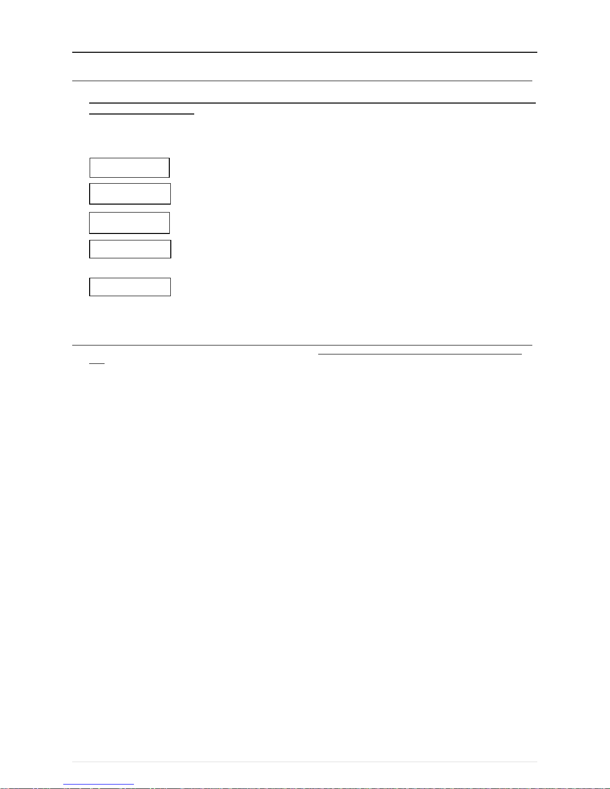
1. Turn off the
breakers
2. Take electrical
shock precautions
3. Use appropriate
tools
4. Ground
5. Clean
Page 9

[III System restrictions and notes]
5
III System restrictions and notes
[1] System configuration restrictions ............................................................................................... 6
[2] System Connection Examples ................................................................................................. 10
[3] Restrictions and Notes on AC Power Supply Wiring .............................................................. 17
[4] Restrictions and Notes on Transmission Wiring ..................................................................... 17
[5] M-NET address settings .......................................................................................................... 19
[6] Restrictions and notes on network wiring ................................................................................ 20
[7] IP address settings ................................................................................................................... 21
[8] Switch Settings ......................................................................................................................... 22
[9] Other points to note .................................................................................................................. 23
Page 10
[III System restrictions and notes]
6
[1] System configuration restrictions
(1) Managed equipment
The devices that AE-200/AE-50/EW-50 can control are shown in the following table.
[Legend] ○: Use possible, ×: Use not possible
S series ○ ○ ○
Y seri es*1
○ ○ ○
HP series
○ ○ ○
R2 series*1
○ ○ ○
WY series
○ ○ ○
WR2 series
○ ○ ○
HVRF serie s
○ ○ ○
○ × ×
○ ○ ×
○*2 ○*3
×
○
○*3
×
× × ×
○*2 ○*3
×
○ × ○
○ ○ ×
○ ○ ×
○ ○ ×
○ × ×
○ × ×
○ × ×
○ × ×
○ × ×
Night mode
CITY MULTI
AHC
HWHP (CAHV/CRHV)
General equipment (DIDO controller connection)
General equipment (indoor unit fr ee contact connecti on)
Monitoring/o
peration
Peak cut
Air To Water (P WFY) Booster unit
Air To Water (P WFY) HEX unit
DOAS (Dedicated Outside Air System)
Commercial PAC (PFAV)
Commercial PAC (PEV/PFV)
Computer room PAC (PFD)*4
LOSSNAY
OA Processi ng unit
A-c ontrol unit (Mr. Slim)
AK-c ontrol unit (Mr. Slim)
K-c ontrol unit
Room air conditioner ( RAC)
Function
Model
*1 Also includes Replace Multi.
*2 A separate adapter is required.
A-control (Mr. Slim) model: M-NET connection adapter
Room air conditioner: M-NET control interface
*3 Only set temperature control or stop control can be performed for RAC and HAC.
*4 When the Computer room PAC is in maintenance mode, operation is not possible.
Page 11
[III System restrictions and notes]
7
Apportioned electricity billing function [Legend] ○: Use possible, ×: Use not possible
Metering method
Manual input method
S series
○ ○
Y series
○
○
HP series
○ ○
R2 series
○
○
WY series
○ ○
WR2 series
○
○
HVRF series
×
×
○ ○
○
○
○ ○
× ×
×
×
○
*3
×
○ ○
×
×
○ ○
○
○
○
○
× ×
× ×
○
*3
×
○*3
×
Room air conditioner ( RAC)
Apportioned electricity billing f unction*2
CITY MULTI
AHC
LOSSNAY
OA Processi ng unit
A-c ontrol unit (Mr. Slim)* 1
AK-control unit ( Mr. Slim)*1
K-c ontrol unit
General equipment (DIDO controller connection)
General equipment (indoor unit free contact connecti on)
Air To Water ( PWFY) Booster uni t
DOAS (Dedicated Outside Air System)
Commercial PAC (PFAV)
Commercial PAC (PEV/PFV)
Computer room PAC (PFD )
HWHP (CAHV/C RHV)
Function
Model
*1 [Capacity save amount] can be selected in outdoor unit apportioned electricity mode only when the M-NET adapter is one of the
following models.
PAC-SJ19MA-E, PAC-SJ83MA-E
*2 Registration of the license is required for each AE-200/AE-50/EW-50.
*3 The apportioned electricity billing function can be used if an electricity meter is connected individually to each unit.
Bar graph and line graph for energy management (*1) [Legend] ○: Use possible, ×: Use not possible, -: No item
Electric energy amount
Fan operat ion time
Thermostat on (total)
Thermostat on (cool ing)
Thermostat on (heating)
Meter values
Outdoor air temperature
Set cooli ng temperature
Set heat ing tem perature
Indoor temper ature
Measured v alue
S series
○ ○ ○ ○ ○
Y series ○ ○ ○ ○
○
HP series
○ ○ ○ ○ ○
R2 series
○ ○ ○ ○ ○
WY series ○ ○ ○ ○
○
WR2 series
○ ○ ○ ○ ○
HVRF series ○ ○ ○ ○ ○
× ○
- - -
○ ○ ○ ○
○
○ ○ ○
○ ○
○ ○
○ ○ ○
×
× × × ×
○ ○
○ ○ ○
○
○*2
○ ○ ○
○ ○ ○ ○ ○
○ ○ ○ ○ ○
○ ○ ○ ○ ○
○ ○ ○ ○ ○
-
- - - -
- - -
- -
× ×
- - -
× ×
- - -
×
○
○
○
○
-
×
○
○
-
×
Bar gr aphs
Line graphs
Measurement val ues of P I c ontroller c an be display ed
Measurement val ues of A H C and A I contr oller can be dis play ed
Measurement val ues of A H C and A I contr oller can be dis play ed
○
○
○
○○○
○
×
○
○
○
Room air condi ti oner (RAC)
CITY MUL TI
AHC
LOSSNAY
OA Processi ng unit
A-control unit ( Mr. Slim)
AK-control unit ( Mr . Slim)
K-control unit
General equipment (DIDO controller connection)
General equipment (indoor unit fr ee contact connection)
Air To W ater (PWFY) Booster unit
DOAS (Dedicated Outside Air System)
Commercial PAC (PFAV)
Commercial PAC (PEV/PFV)
Computer room PAC (PFD )
HWHP (CAHV /CRHV )
Graph display details
Model
*1 Registration of the license is required for each AE-200/AE-50/EW-50.
*2 Becomes the cumulative operation time.
● The above functions are subject to change without notice for improvement.
Page 12
[III System restrictions and notes]
8
(2) Number of connectible/controllable units in a system
1. Number of controllable units for AE-200/AE-50/EW-50
Item
Description
Managed equipment
Number of controllable
indoor units
Max. 50 *1
IC, LC, FU, AIC, RAC, PWFY, HWHP,
AI controllers, PI controllers, DIDO controllers*2, AHC*3
[Code] IC: Indoor unit (OA Processing unit [without interlock control]), LC: Free-plan LOSSNAY,
FU: OA Processing unit (with interlock control), AIC: Mr. Slim air conditioner, RAC: Room air conditioner,
PWFY: Air To Water (PWFY), HWHP: HWHP (CAHV, CRHV)
*1 AE-50 cannot be operated individually.
*2 One contact is counted as one unit for a DIDO controller.
*3 Maximum number of connectible/controllable units in the case of AHC: Indoor units + AHC = 70 units.
2. Number of controllable units in an AE-200 + expansion controller (AE-50/EW-50) system
Item
Description
Managed equipment
Number of controllable
indoor units
Max. 200 (When using three
AE-50/EW-50)*1
IC, LC, FU, AIC, RAC, PWFY, HWHP, AI con trollers, PI
controllers, DIDO controllers*2, AHC*3
*1 When M-NET of AE-200 is not used or the apportioned electricity billing function of AE-200 is used, four AE-50/EW-50 units can
be connected. (Max. 200 indoor units)
*2 One contact is counted as one unit for a DIDO controller.
*3 Maximum number of connectible/controllable units in the case of AHC: Indoor units + AHC = 70 units.
(3) When performing integrated centralized control with the integrated centralized control software TG-2000A.
Use Ver.6.60 or later of TG-2000A.
(4) Number of connectable units
The table below summarizes the number of connectable units in an M-NET system.
Unit type
Number of connectable units
Indoor units, PWFY, HWHP, LOSSNAY, OA Processing unit, DIDO
controllers, PI controllers*1, and AI controllers per AE-200/AE-50/EW-50
Up to 50 units*2 (including the interlocked LOSSNAY units)
AHC per AE-200/AE-50/EW-50
Maximum of 70 indoor units for indoor units+AHC
Indoor units, PWFY, HWHP, LOSSNAY, OA Processing unit, and DIDO
controllers in one group
1–16 units*3*4
(Indoor units, PWFY, HWHP, LOSSNAY, OA Processing unit, and
DIDO controllers cannot be used together in the same group.)
AHC in a group
1 unit
(At least one indoor unit is required in the same group.)
Remote controllers in a group
0–2 units
System controllers in a group
(AE-200/AE-50/EW-50 included)
0–5 units
(Up to four remote and system controllers combined can be
assigned to each group.)
LOSSNAY unit that can be interlocked with each indoor unit
1 unit
Indoor units that can be interlocked with each LOSSNAY unit
1–16 units
*1 15 PI controllers can be connected to each AE-200/AE-50/EW-50 and a maximum of 20 can be connected within an AE-200 system.
A PI is counted as one unit.
*2 By connecting AE-50/EW-50 controllers to an AE-200, up to 200 units can be controlled.
*3 The maximum number of controllable units for DIDO controllers differs depending on the number of channels used.
*4 One contact of a DIDO controller is calculated as one unit.
Page 13
[III System restrictions and notes]
9
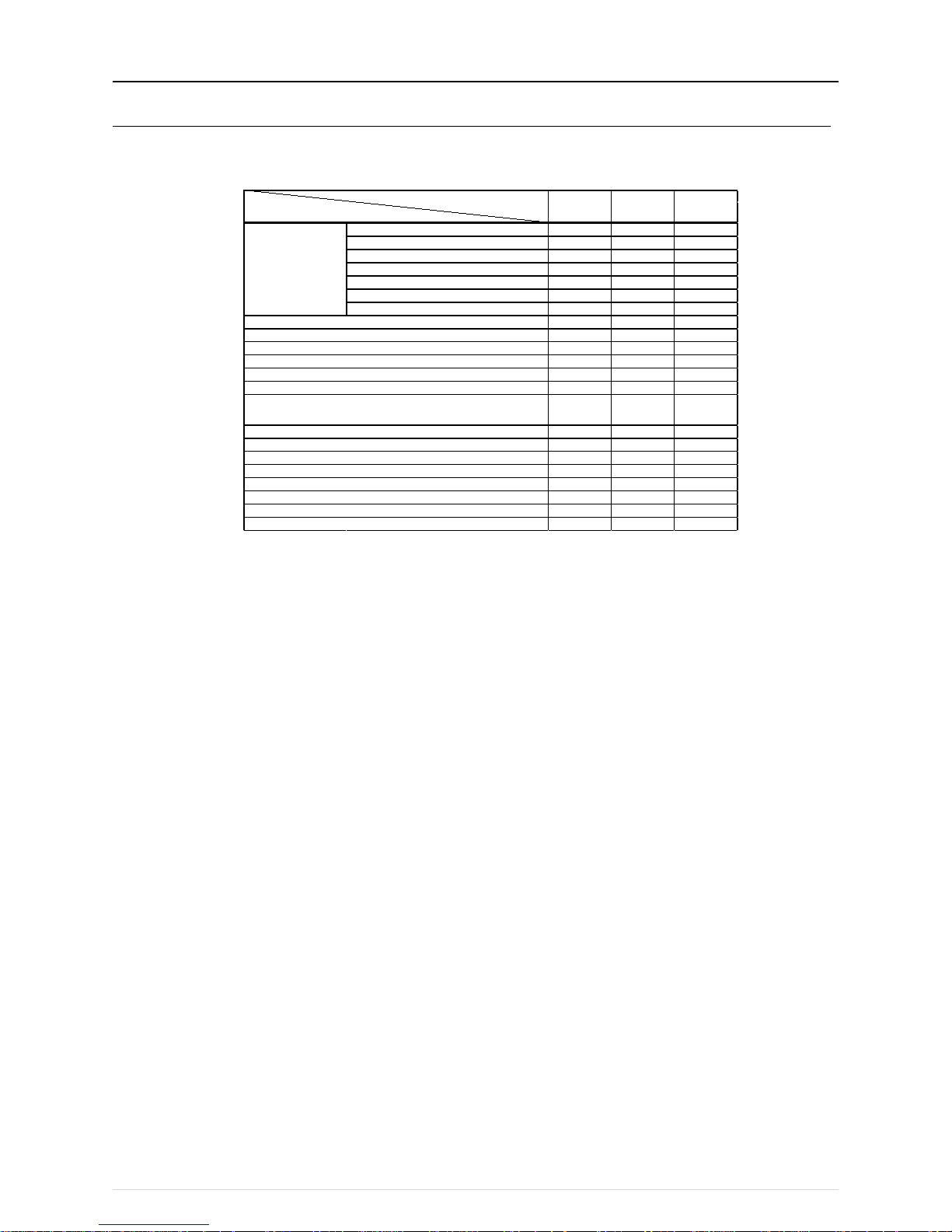
(5) Operation block setting restrictions
・ An operation block is a collection of groups, and groups of different models (air-conditioning units, LOSSNAY, general equipment,
etc.) can even be set in the same operation block.
・ An operation block that spans AE-200/AE-50/EW-50 systems cannot be set.
・ The operation items differ so we recommend setting operation blocks separately for each of the indoor units, LOSSNAY units,
and A-control models.
・ When peak-cut control is used, blocks become the setting target unit so be sure to set the operation blocks.
(6) Energy management block setting restrictions
・ An energy management block is a collection of operation blocks and OA Processing unit (with interlock control), and operation
blocks of different models (air-conditioning units, LOSSNAY, general equipment, etc.) can also be set in the same energy
management block.
・ An energy management block that spans multiple AE-50/EW-50 in an AE-200 system can be set, but an energy management
block cannot span multiple AE-200 systems.
・ When the apportioned electricity billing function is used, energy management blocks become the apportioning target unit so be
sure to set the energy management blocks.
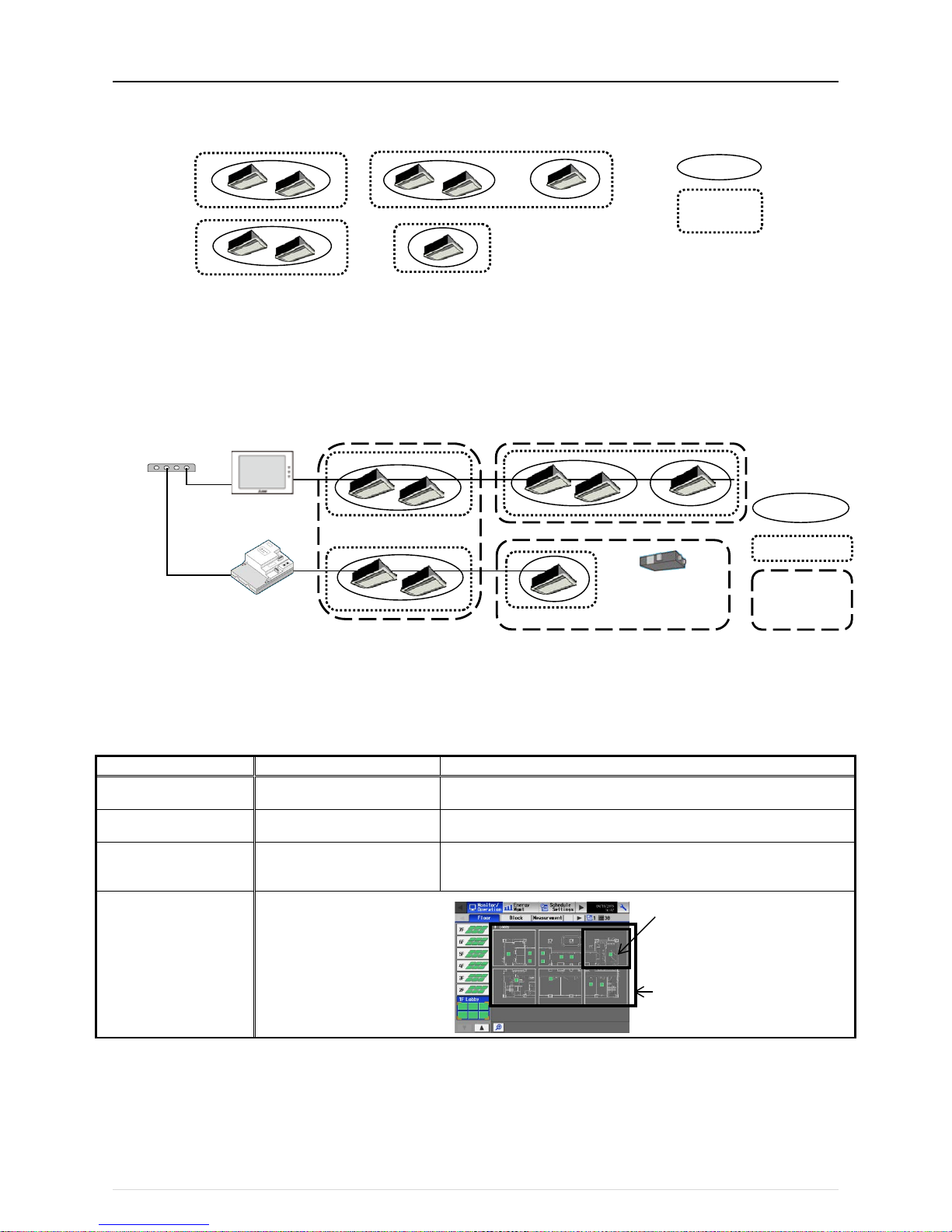
(7) Group setting restrictions
Restrictions also apply to group settings.
Item
Description
Remark
Number of remote controllers
that can be connected
Up to two remote controllers in one
group
MA remote controllers do not need to be registered and set on this equipment.* 1
Number of indoor units that can
be connected in one group
1 to 16 IC, AIC, FU, and LC cannot be connected to the same group.
However, groups that span multiple AE-200/AE-50/EW-50 cannot be configured.* 2
Number of SC and RC units
that can be connected in one
group
Up to four units in one group
Number of groups per area
Number of groups per floor
Up to 30 groups per area
Up to 180 groups per floor
*1 An ME remote controller and MA remote controller cannot be used together in the same group.
*2 If a group is made up of indoor units with different functions, only the function of the indoor unit with the lowest address in the
group is operated and monitored.
Group
Operation
block
[Floor]
Up to 180 groups can be placed
[Area]
Up to 30 groups can be placed
Group
Operation block
Energy
management
block
OA Processing unit
(with interlock control)
AE-200
EW-50
HUB
LAN
LAN
Page 14
[III System restrictions and notes]
10
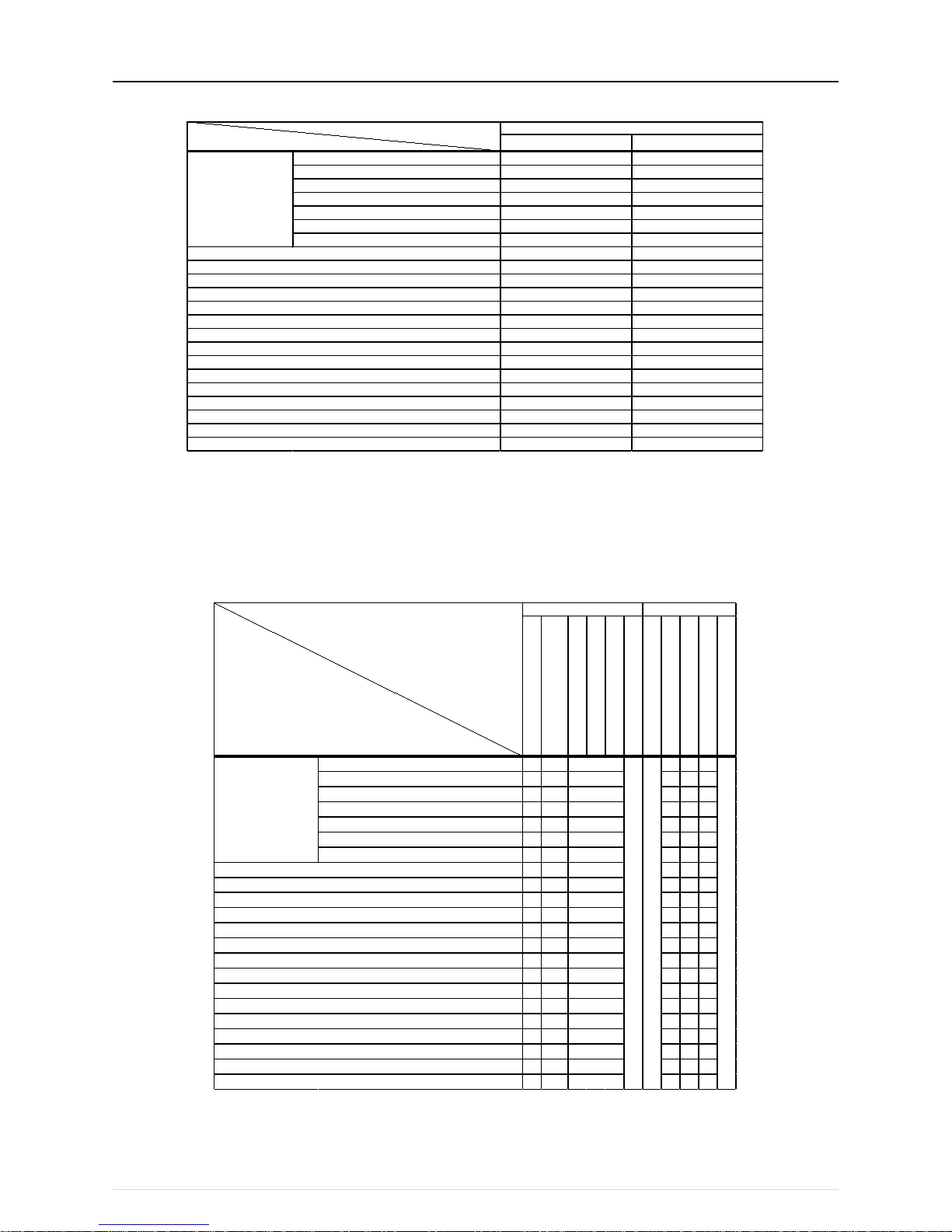
[2] System Connection Examples
The following shows the equivalent power supply of the AE-200/AE-50/EW-50 and transmission line power supply unit and the
equivalent power consumption and the equivalent number of units of the DIDO controller, PI controller, and AI controller.
Leave the power jumpers (CN41) of the outdoor units that are connected to M-NET centralized control transmission lines all
connected to the CN41 in the same way as they were connected at the time of shipment.
If the equivalent power supply is insufficient because system remote controllers and other equipment are connected to the M-NET
centralized control transmission lines, transmission line power supply units need to be added.
When connecting system remote controllers and other equipment to the M-NET centralized control transmission lines, make sure
that the equivalent number of units total will be 40 or less.
If the equivalent number of units will exceed 40, add transmission line power supply units so that the equivalent number of units will
be 40 or less.
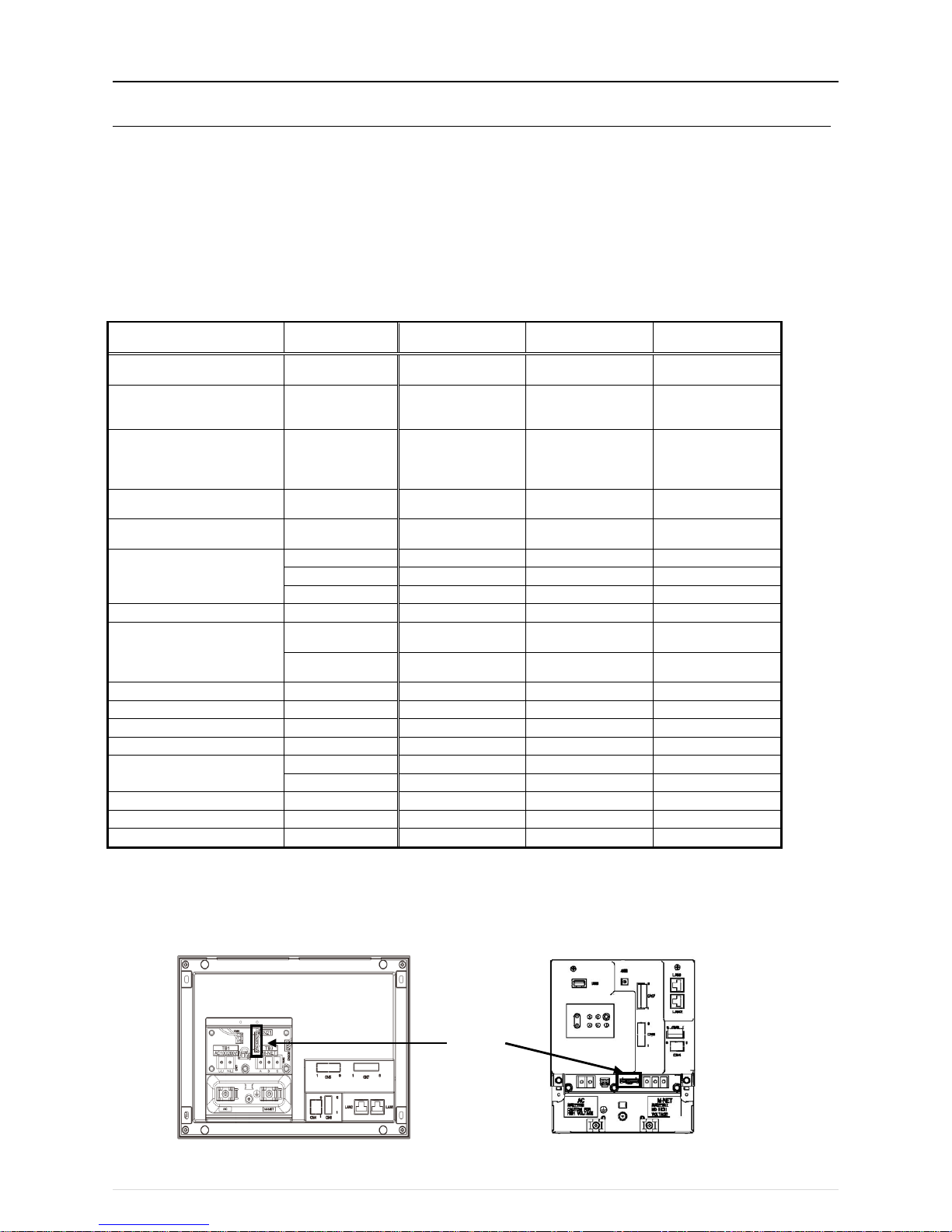
To supply M-NET power from a transmission line power supply unit, disconnect the CN21 jumper from the AE-200/AE-50/EW-50.
NOTE:
○ If you remove the service cover from the back of the unit, you will find the power jumper (CN21) of the AE-200/AE-50 in the place
indicated in the figure below.
○ If you remove the service cover from the front of the unit, you will find the power jumper (CN21) of the EW-50 in the place indicated in
the figure below.
Product Model
The equivalent power
supply
The equivalent power
consumption
The equivalent
number of units
Air Conditioning Control System
Centralized Controller
AE-200 0 - -
Air Conditioning Control System
Centralized Controller
(Expansion controller)
AE-50 0 - -
Air Conditioning Control System
Centralized Controller
(Controller or Expansion Controller
without LCD)
EW-50 1.5 - -
Power Supply Unit for
Transmission Line
PAC-SC51KUA 5 - -
Power Supply Expansion Unit for
Transmission Line
PAC-SF46EPA 25 - -
System Remote Controller
AT-50B, TC-24B
-
1.5
5
AT-50A, TC-24A
-
1.5 5
PAC-SF44SRA - 1/2
1
ON/OFF Remote Controller PAC-YT40ANRA - 1 1
ME Remote Controller
PAR-U02MEDA,
PAR-U01MEDU
- 1/2 1
PAR-F27MEA,
PAR-F27MEA-US
- 1/4 1
AHC
PAC-IF01AHC-J
-
1/2
1
DIDO Controller PAC-YG66DCA - 1/4 1
PI Controller
PAC-YG60MCA
-
1/4
1
AI Controller PAC-YG63MCA - 1/4 1
MN Converter
CMS-MNG-E - 2
1
CMS-MNF
-
1/2 1
Simple ME Remote Controller
PAC-SE51CRA - 1/4
1
Group Remote Controller PAC-SC30GRA
-
1/2
1
Schedule Timer
PAC-YT34STA
-
1/2
1
AE-200/AE-50
CN21
EW-50
Page 15
[III System restrictions and notes]
11
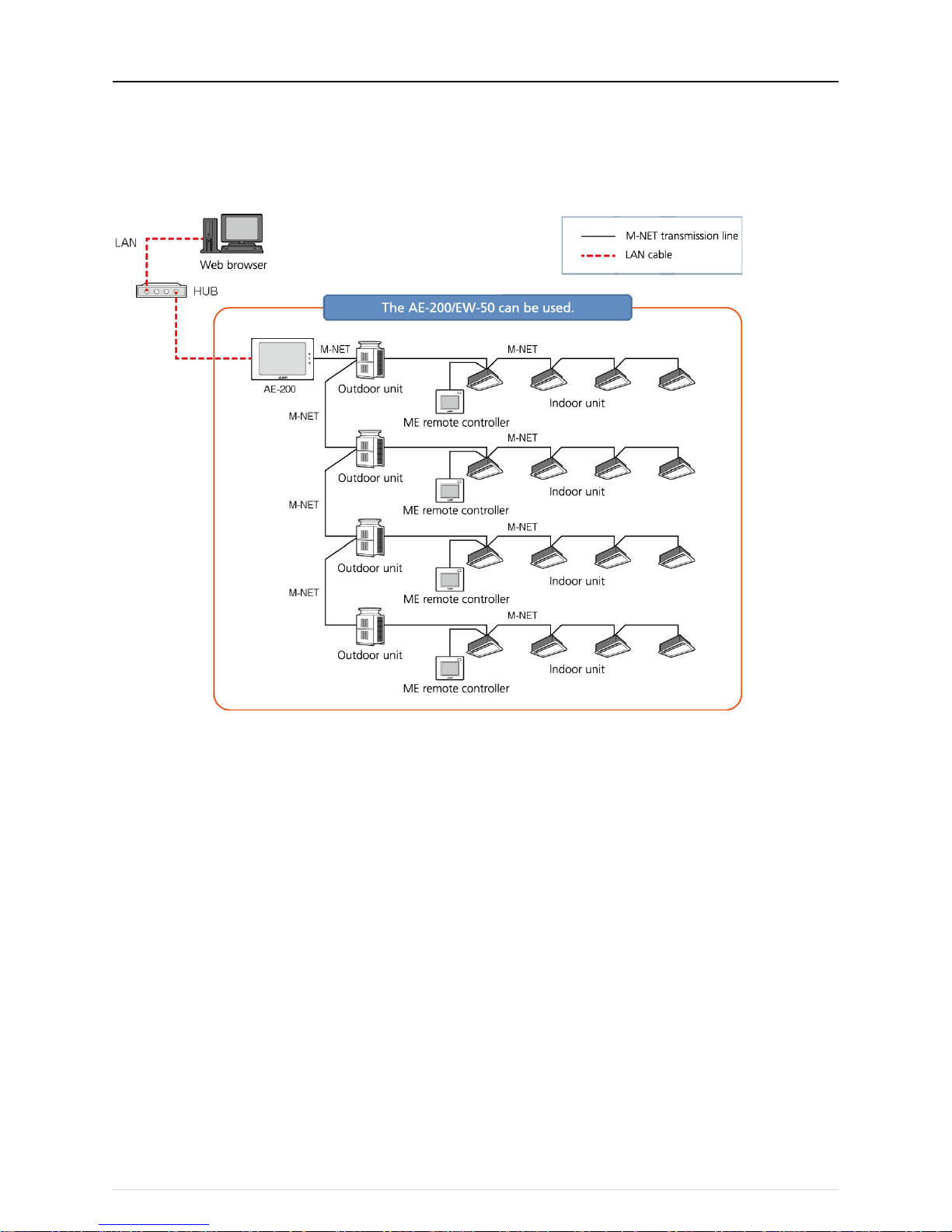
(1) When using the M-NET transmission line of the AE-200 and there are 50 or fewer air-conditioning units (apportioned electricity billing
function is not used)
With the AE200, up to 50 air-conditioning units can be monitored and operated from the unit LCD screen or a Web browser.
Also, if the EW-50 is connected instead of the AE-200, monitoring and operation from a Web browser are possible.
・ The AE-50 cannot be used on its own.
Page 16

[III System restrictions and notes]
12
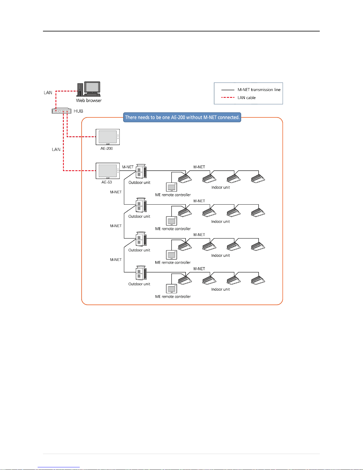
(2) When using the M-NET transmission line of the AE-200 and there are 51 or more air-conditioning units (apportioned electricity billing
function is not used)
Up to 200 air-conditioning units can be monitored and operated by using three AE-50/EW-50 expansion controllers.
・ When using the Web browser function, access each AE-200/AE-50/EW-50 to perform monitoring and operation.
Page 17
[III System restrictions and notes]
13
(3) When there are 50 or fewer air-conditioning units (apportioned electricity billing function is not used and M-NET transmission of the
AE-200 is not used)
When M-NET is connected to one AE-50 expansion controller, and AE-200 is used without using M-NET transmission line, up to 50
air-conditioning units can be monitored and operated from two AE-200/AE-50 locations.
Also, monitoring and operation from an AE-200 can be performed by connecting an EW-50 in the same way.
・ When using the Web browser function, access each AE-50/EW-50 t o perform monitoring and operation.
Page 18

[III System restrictions and notes]
14
(4) When there are 51 or more air-conditioning units (apportioned electricity billing function is not used and M-NET transmission of the
AE-200 is not used)
Up to 200 air-conditioning units can be monitored and operated by connecting an AE-200 and up to four AE-50/EW-50 expansion
controllers.
・ When using the Web browser function, access each AE-50/EW-50 t o perform monitoring and operation.
Page 19
[III System restrictions and notes]
15
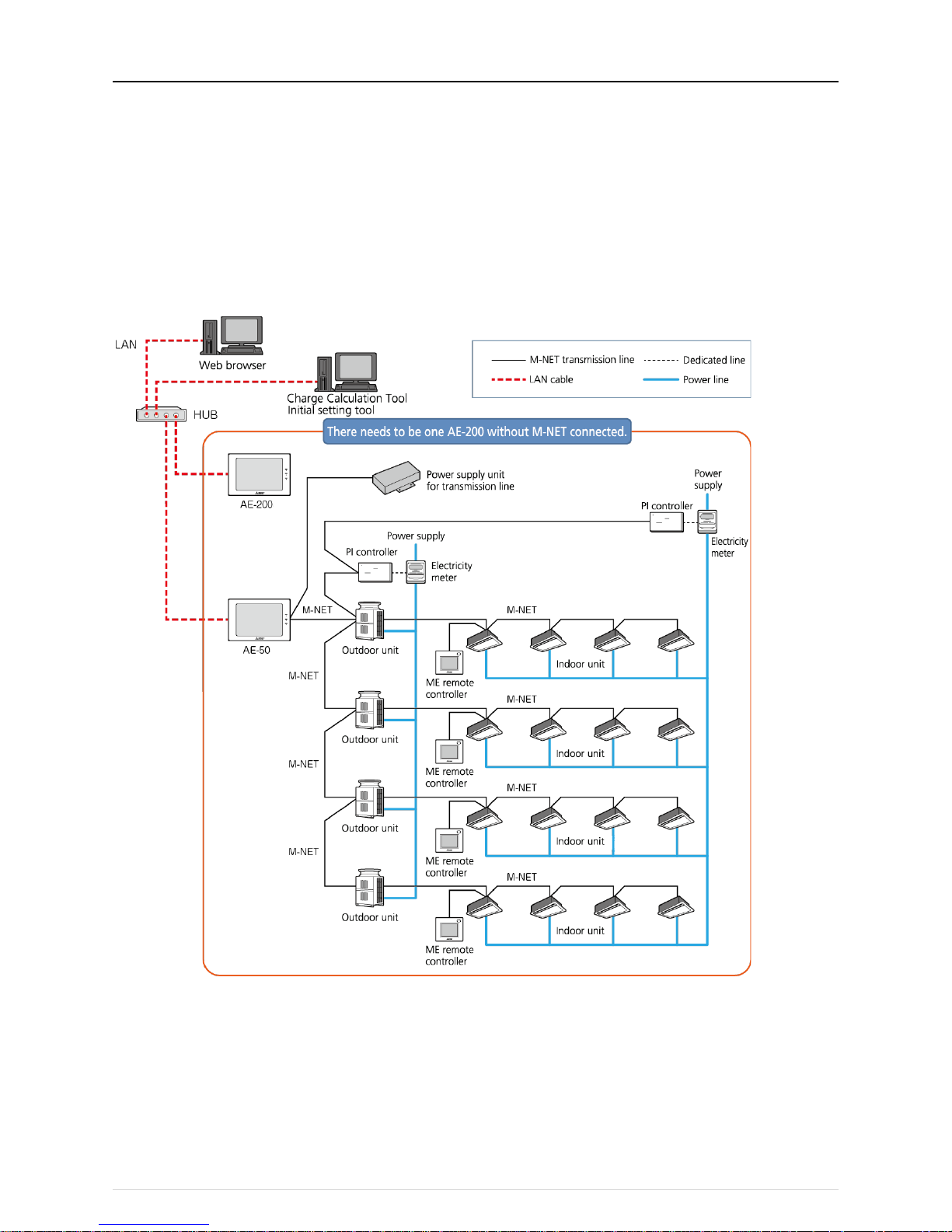
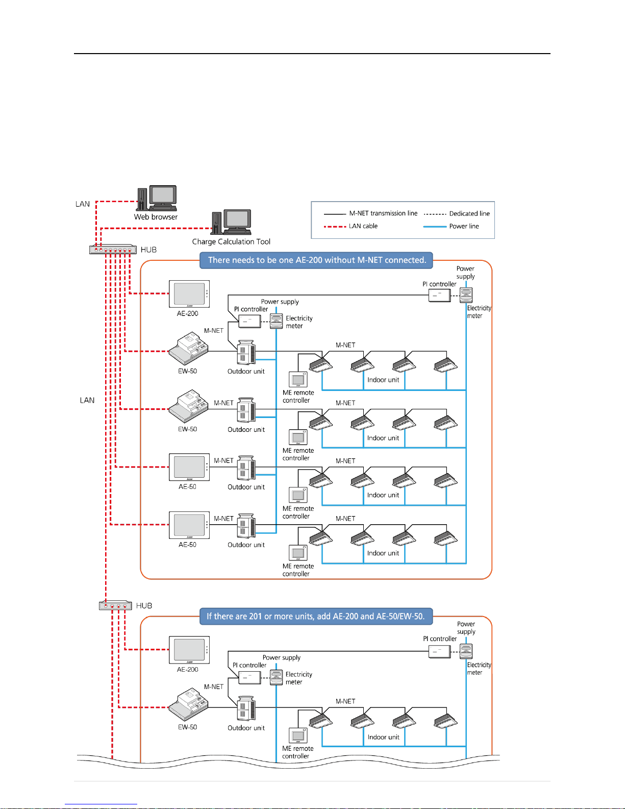
(5) When using the apportioned electricity billing function and there are 50 or fewer air-conditioning units
Each AE-50/EW-50 expansion controller can monitor and operate up to a total of 50 air-conditioning units using the apportioned
electricity billing function.
・ When the apportioned electricity billing function is used, the combination of an AE-200 (without M-NET connection) and
AE-50/EW-50 expansion controller is required to obtain a backup of the data.
・ When the apportioned electricity billing function is used, the M-NET transmission line of the AE-200 cannot be used.
・ When using the Web browser function, access the AE-50/EW-50 to perform monitoring and operation.
・ Registration of the license is required for each centralized controller.
・ An electricity meter needs to be connected to each AE-200 system. Electricity meters connected to other AE-200 systems cannot
be set.
・ To set the apportioned electricity billing function, Initial Setting Tool is required.
・ To perform the charge calculation of the apportioned electricity billing function, Charge Calculation Tool is required.
・ When using the apportioned electricity billing function, use Ver.7.23 or later of AE-200/AE-50/EW-50.
Page 20
[III System restrictions and notes]
16
(6) When using the apportioned electricity billing function and there are 51 or more air-conditioning units
By using4 AE-50/EW-50 expansion controllers, up to a total of 200 air-conditioning units can be monitored and operated using the
apportioned electricity billing function.
・ When the apportioned electricity billing function is used, the M-NET transmission line of the AE-200 cannot be used.
・ When using the Web browser function, access the AE-50/EW-50 to perform monitoring and operation.
・ Registration of the license is required for each centralized controller.
・ An electricity meter needs to be connected to each AE-200 system. Electricity meters connected to other AE-200 systems cannot
be set.
・ To set the apportioned electricity billing function, Initial Setting Tool is required.
・ To perform the charge calculation of the apportioned electricity billing function, Charge Calculation Tool is required.
・ When using the apportioned electricity billing function, use Ver.7.23 or later of AE-200/AE-50/EW-50.
Page 21
[III System restrict i o ns and notes]
17
[3] Restrictions and Notes on AC Power Supply Wiring
(1) Notes
1. Perform electrical work in accordance with the instructions in the installation manual.
2. To prevent electrical noise from the power supply wiring affecting the wiring for transmission (control), lay the power supply wiring
at least 5 cm (2 in) apart if laying the wiring in parallel.
(Do not insert them in the same conduit.)
3. Be sure to connect the ground wire for protection.
4. Select electrical wiring that meets the requirements in the following table.
Recommended power
cable type
VCT, VVF, VVR, or its equivalent
Power cable size 0.75 to 2.00 mm2 (ø1.0 to ø1.6 mm)
[4] Restrictions and Notes on Transmission Wiring
(1) Notes
1. Perform electrical work in accordance with the instructions in the installation manual.
2. To prevent the wiring for transmission (control) from being affected by electrical noise from the power supply wiring, lay the wiring
for transmission (control) at least 5 cm (2 in) apart from the power supply wiring.
(Do not insert them in the same conduit.)
3. Never connect a 100 V or 200 V power supply to the terminal block for the transmission wiring. In the event that a power supply
is connected, the electrical components will burn out.
4. Use a 2-core shielded cable for the transmission wiring. Never use the same cable with multiple cores for wiring multiple systems
because the transmission signals will become unable to be sent and received normally, resulting in erroneous operation.
(2) M-NET transmission line
The type and tolerance of wiring differ depending on the system configuration. Furthermore, if the transmission line is long and there
is a noise source within the vicinity of a unit, move the noise source away from the unit to prevent noise interference.
Transmission line type*1
CPEVS ø1.2 to ø1.6 mm: PE insulated PVC jacketed shielded communication cable
CVVS, MVVS 1.25 to 2 mm
2
: PVC insulated PVC jacketed shielded control cable
Maximum length for
indoor/outdoor transmission
line
Max. 200 m (656 ft)
Farthest distance for
M-NET transmission line
(maximum length via an
outdoor unit)
Max. 500 m (1640 ft)
* The maximum wire length from the transmission line power supply unit installed for the
centralized control transmission line to each outdoor unit and system controller is 200 m (656 ft).
*1 PE: Polyethylene, PVC: Polyvinyl chloride
(3) Remote controller line
MA remote controller*1
M-NET remote controller*2
Wiring type
Type
VCTF, VCTFK , CVV , CVS ,
VVR, VVF, VCT
10 m (32 ft) or less
If 10 m (32 ft) is exceeded
Shielded wire CVVS,CPEVS,MVVS
Number
of wires
2-core cable
2-core cable
Wire
diameter
0.3 to 1.25 mm2*3*4
(0.75 to 1.25 mm2)*5
0.3 to 1.25 mm2*3*4
(0.75 to 1.25 mm2)*5
At least 1.25 mm
2
Total length
Max. 200 m (656 ft)*6
Max. 10 m (32 ft)
The portion that exceeds 10 m
(32 ft) must be included in the
calculation for the maximum
length of the indoor/outdoor
transmission line.
*1 MA remote controllers include simple MA remote controllers and wireless remote controllers.
*2 M-NET remote controllers refer to ME remote controllers and LOSSNAY remote controllers.
*3 A wire diameter of up to 0.75 mm
2
is recommended.
*4 When connecting an MA remote controller, use a 0.3 mm
2
cable with a sheath for the wiring.
*5 When connecting to the terminal block of a simple MA remote controller, use wire with a diameter within the parentheses.
*6 Maximum 100 m (328 ft) w hen connecting a pair of remote controllers including an MA remote controller.
Page 22
[III System restrictions and notes]
18
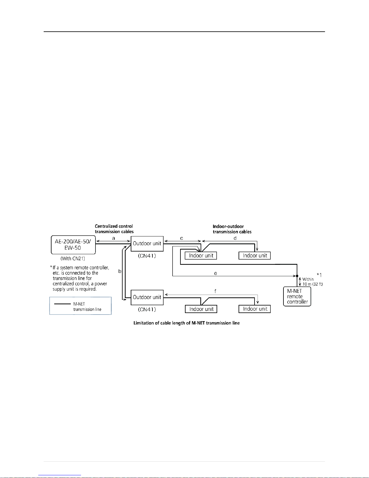
The following shows an example of a wiring diagram for the M-NET transmission line of CITY MULTI.
The example in the figure below shows the cable length limit of centralized control M-NET transmission line and indoor-outdoor M-NET
transmission line for each system.
1. Farthest distance for M-NET transmission line (limited by attenuation of the signal waveform)
・ Make the distance between the transmission source and transmission destination of signals no more than 500 m (1640 ft).
If this maximum distance is exceeded, communication will become impossible due to the attenuation of the waveform.
a+c+d ≤ 500 m (1640 ft), a+c+e ≤ 500 m (1640 ft), a+b+f ≤ 500 m (1640 ft), c+d+b+f ≤ 500 m (1640 ft), c+e+b+f ≤ 500 m
(1640 ft)
2. Maximum power supply distance for M-NET transmission line (limited by voltage drop)
(1) Maximum total length of power feed for the centralized control transmission lines
・ Make the distance between the supply source and supply destination of power no more than 200 m (656 ft).
If this maximum distance is exceeded, communication will become impossible due to the voltage drop.
a+c+d ≤ 200 m (656 ft), a+c+e ≤ 200 m (656 ft), a+b+f ≤ 200 m (656 ft)
* If a system remote controller, etc. is connected to the transmission line for centralized control, a power supply unit
(PAC-SC 51KUA) is required.
* There are cases where the supply source and supply destination of M-NET power differ depending on the setting of the
M-NET supply connector.
(2) Maximum total length of power feed for the indoor-outdoor transmission lines
・ Make the distance from an outdoor unit to the supply destination no more than 200 m (656 ft).
c+d ≤ 200 m (656 ft), c+e ≤ 200 m (656 ft)
*1 The wiring length of the M-NET remote controller must be 10 m (32 ft) or less. If 10 m (32 ft) is exceeded, the portion that
exceeds 10 m (32 ft) must be included in the calculations for the maximum total wiring length of the M-NET transmission line
(500 m (1640 ft)) and the maximum total power supply distance (200 m (656 ft)).
Page 23
[III System restrictions and notes]
19
[5] M-NET address settings
The setting range for the address setting differs depending on the device.
(1) AE-200
Use "0" (factory setting) for the address of the AE-200.
Change it to a value within the range of 201 to 250 only if it duplicates the address of another controller (BM adapter, etc.).
Address setting range Setting method When enabled
Unit address 0, 201–250
Any address within the address range on
the left.
Always*1
(Network setting screen)
*1 The setting is applied after a restart. (A restart is performed automatically after the setting is changed.)
The setting can be checked from the network setting screen of the LCD screen or a Web browser.
(2) AE-50/EW-50
Use "0" (factory setting) for the address of the AE-50/EW-50.
Change it to a value within the range of 201 to 250 only if it duplicates the address of another controller (BM adapter, etc.).
Address setting range Setting method When enabled
Unit address 0, 201–250
Any address within the address range on
the left.
Always*1
(Network setting screen)
*1 The setting is applied after a restart. (A restart is performed automatically after the setting is changed.)
The setting can be checked from the network setting screen of the LCD screen or a Web browser.
(3) Various M-NET devices
Designate the address for each M-NET device. The addresses cannot be overlapped within the same M-NET system.
Address setting method
M-NET
address
Indoor unit
Assign the lowest address to the main indoor unit in the group, and assign
sequential addresses to the rest of the indoor units in the same group.
1–50
Outdoor unit
Assign an address that equals the lowest indoor unit address in the same
refrigerant system plus 50.
51–100
Auxiliary outdoor unit
(BC controller etc.)
Assign an address that equals the address of the outdoor unit in the same
refrigerant system plus 1.
52–100
Interlocked OA Processing
unit/LOSSNAY
Assign an arbitrary but unused address to each of these units after assigning
an address to all indoor units.
1–50
A-control Mr. Slim outdoor unit
Make the settings in the same way as with the indoor units. Requires
PAC-SJ19MA-E/PAC-SJ83MA-E (sold separately).
1–50
Room air conditioner
Make the settings in the same way as with the indoor units. Requires
MAC-333IF (sold separately).
1–50
AHC
Assign an address that equals the address of the main indoor unit with the
lowest address in the group plus 200. If the address overlaps with the Sub
system controller’s address, assign an arbitrary but unused address between
201 and 250 to the Advanced HVAC CONTROLLER.
201–250
Air To Water (PWFY) unit
Make the settings in the same way as with the indoor units.
1–50
HWHP (CAHV, CRHV) unit
(Main Box)
Make the settings in the same way as with the indoor units.
1–50
HWHP (CAHV, CRHV) unit
(Sub Box)
Assign addresses that equal the addresses of the main and sub units in the
Main Box plus 50 to the units in the Sub Box.
51–100
M-NET remote controller
Assign an address that equals the address of the main indoor unit with the
lowest address in the group plus 100. Add 150 instead of 100 to set the
address for a sub remote controller.
101–200
MA remote controller
Address setting is not required.
Connection of two remote controllers requires the Main/Sub setting for each
controller to be made.
-
Sub System controller
Assign an address that equals the group number of the smallest controlled
group plus 200.
201–250
DIDO controller
Assign an arbitrary but unused address to the controller after completing the
address setting for the units with an address between 1 and 50. The number
of controllable units varies with the number of channels used.
1–50
PI controller
Assign an arbitrary but unused address to the controller after completing the
address setting for the units with an address between 1 and 50.
1–50
AI controller
Assign an arbitrary but unused address to the controller after completing the
address setting for the units with an address between 1 and 50.
1–50
* Some models cannot be controlled from the AE-200/AE-50/EW-50.
For details on the managed equipment, refer to "III [1] (1) Control target equipment."
Page 24
[III System restrictions and notes]
20
[6] Restrictions and notes on network wiring
NOTE:
When connecting the AE-200/AE-50/EW-50 to t he Internet, be sure to use a VPN router or other security device to prevent
unauthorized access.
(1) About LAN
We recommend using 100BASE-TX for the LAN.
Also, with regard to the category of LAN cables, use category 5 or better for reasons such as availability and connectivity with optical
cables (100BASE-FX).
The main cable type is shown in the following table.
LAN standard Cable specification
Maximum
wiring length
Communication
speed
100BASE-TX
Twisted pair cable (T)
100 m (328 ft)
100 Mbps
(2) About HUB
Use a switching HUB for the HUB.
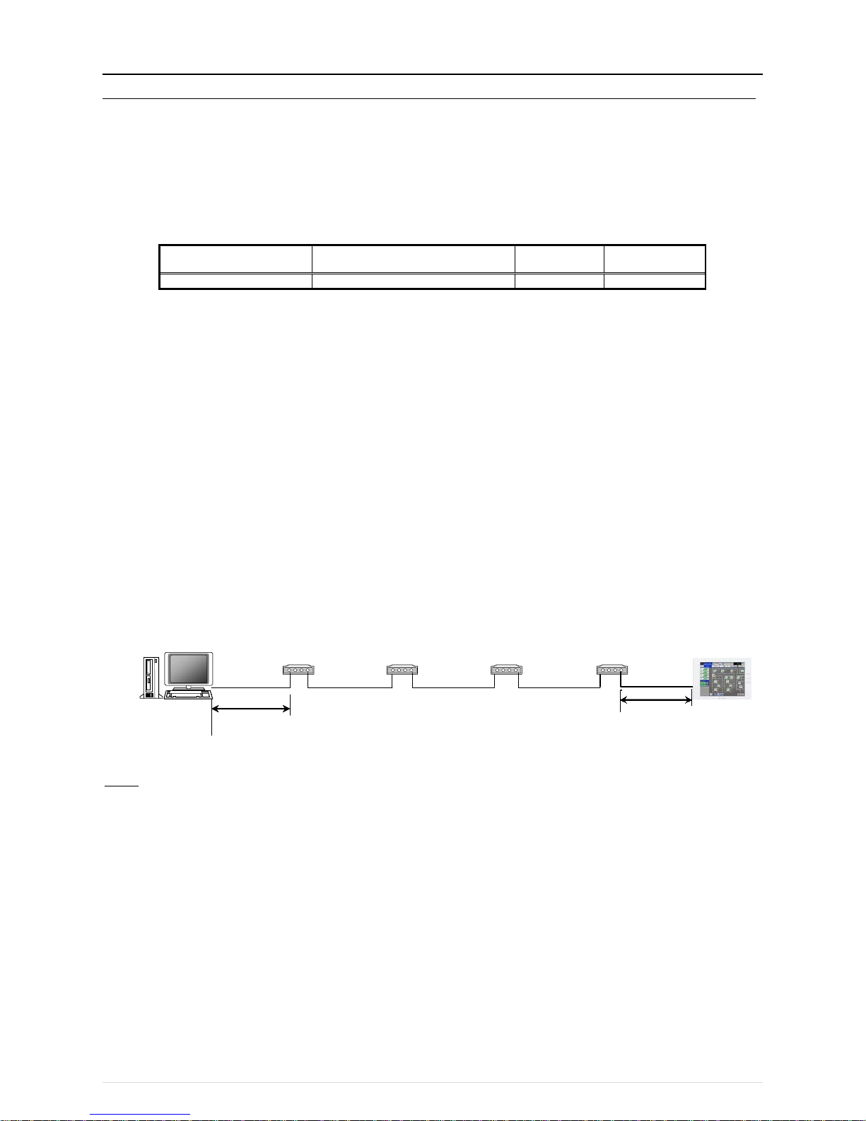
(3) LAN cable length
The maximum cable length for 100BASE-TX when connecting to the A E-200/AE-50/EW50 is 100 m (328 ft).
Therefore, if the LAN cable length exceeds 100 m (328 ft), you can increase the distance between the PC for state monitoring and
operation and the AE-200/AE-50/EW-50 by connecting via a switching HUB or other device.
NOTE:
For details on the switching HUB, refer the instruction manual supplied with the switching HUB.
There is no limit on the number of switching HUB connections, but if the load on the network becomes extremely high, delays will
occur and connecting normally with the network may not be possible.
The recommended number of devices, including a HUB, gateway, router, or layer 3 switch, to connect between the
AE-200/AE-50/EW-50 is four or less.
(The transmission delay time must be 4 seconds or less round trip. If the transmission delay time needs to be checked because, for
example, five or more devices are connected, refer to "V [5] 2. About the check method using ping.")
If a LAN communication error code appears, check the error as described in "V [5] LAN communication error check procedure."
NOTE:
○ Use commercially available LAN cables.
AE-200/AE-50/EW-50
100 m (328 ft)
PC for status
monitoring/operation
Switching HUB
100 m (328 ft)
Switching HUB
Switching HUB
Switching HUB
Page 25

[III System restrictions and notes]
21
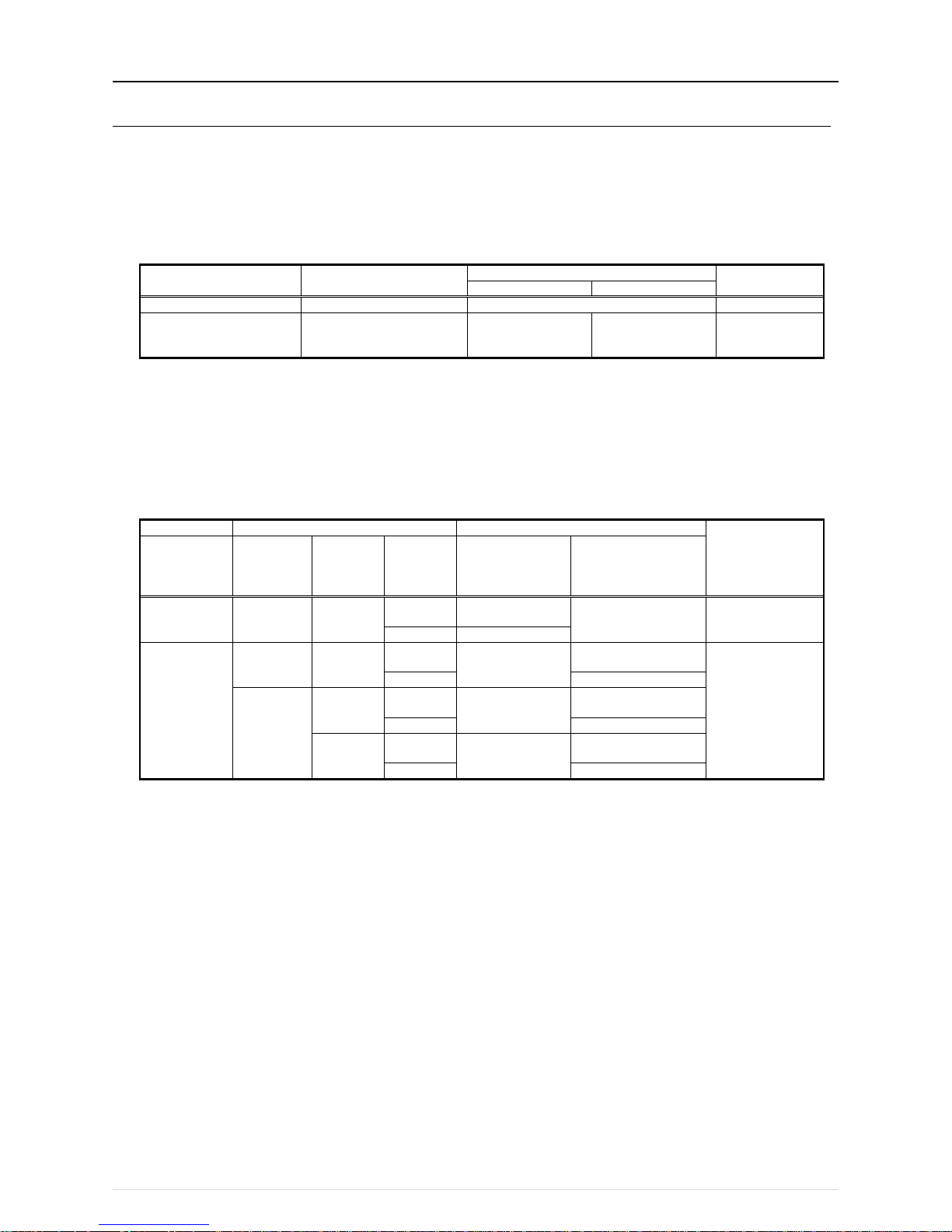
[7] IP address settings
We recommend using the IP addresses in the following table for the AE-200/AE-50/EW-50, TG-2000A, and other equipment when
using a dedicated LAN.
Model
IP address range
AE-200/EW-50 unit *1
[192.168.1.1] to [192.168.1.40]
AE-50/EW-50 unit *1
[192.168.1.211] to [192.168.1.249]
PC for brow ser
[192.168.1.101] to [192.168.1.149]
PC for integrated centralized control software
TG-2000A
[192.168.1.150]
PLC for Electric Amount Count (PAC-YG11CDA)
[192.168.1.151] to [192.168.1.170]
PLC for General Equipment (PAC-YG21CDA)
[192.168.1.171] to [192.168.1.190]
PLC for Demand Input (PAC-YG41CDA)
[192.168.1.191] to [192.168.1.194]
Router
[192.168.1.254]
*1 Set an address within the range of [192.168.1.1] to [192.168.1.40] when using EW-50 individually and within the range of
[192.168.1.211] to [192.168.1.249] when using it as an expansion controller.
Unless otherwise specified, leave the subnet mask of the AE-200/AE-50/EW-50 set to the initial value of [255.255.255.0].
NOTE:
When connecting to an existing LAN, set the IP address and subnet mask specified by the LAN administrator.
The IP address range for various software of PLC differs depending on the model. We recommend using the IP address in the following
table.
Software name
Model name
IP addresses
Electric Amount Count PLC
Software
PAC-YG11CDA [192.168.1.151] to [192.168.1.155]
General Control PLC Software
PAC-YG21CDA
[192.168.1.171] to [192.168.1.190]
Demand Input PLC Software
PAC-YG41CDA
[192.168.1.191] to [192.168.1.194]
Page 26
[III System restrictions and notes]
22
[8] Switch Settings
(1) AE-200/AE-50/EW-50 Switch Settings
The power jumper (CN21) needs to be set (disconnected/connected) depending on the system configuration.
For details, refer to "III [2] System connection examples."
(2) Main board of outdoor units
The following shows the DIP switches to use for a system with the AE-200/AE-50/EW-50 connected.
When connecting the AE-200/AE-50/EW-50, set t he centralized control switch to ON.
Switches Function
Operations according to switch setting
Switch setting
timing
OFF
ON
SWU1, 2
Unit address setting
Set to 51 to 100 with the dial switch
Before power on
SW2–1
(SW 5–1 depending on the
model)
Centralized control switch
Without connection
to centralized
controller
With connection to
centralized controller
Before power on
Change the setting of the power jumper of the outdoor units in accordance with the system to be built.
For details, refer to the illustrations in "III [2] System connection examples."
(3) Indoor Units
The following shows the switch settings to change to the free contact mode that can generally use external inputs and outputs of an
indoor unit.
The free contact compatible models of indoor units are R410A compatible models and R407C compatible Ver.33 or later
*1
.
*1 The version can be verified in the indoor unit version display part in Maintenance Tool.
Function
Switch settings
Other functions
Remarks
Free contact SW1–10 SW1–9 SW1–5
Power ON/OFF
and power failure
automatic
recovery
Remote display
switching
Enabled ON ON
ON
Power failure auto
recovery
Disabled
Differs from switch
setting.
OFF
Disabled
Disabled
ON OFF
ON
Power ON/OFF
Thermostat ON signal
display
Depends on the
original switch
setting.
OFF
Fan output display
OFF
ON
ON
Power failure auto
recovery
Thermostat ON signal
display
OFF
Fan output display
OFF
ON
Disabled
Thermostat ON signal
display
OFF
Fan output display
(Reference) For a model prior to the free contact compatible models, SW1-5 is remote display switching, SW1-9 is power failure auto
recovery, and SW1-10 is power ON/OFF.
Page 27

[III System restrictions and notes]
23
[9] Other points to note
(1) About using General equipment
・ There may be cases when the general equipment cannot be monitored or operated due to, for example, a disconnection of the
wiring between the general equipment or a failure of the DIDO controller or PLC. In such a case, Mitsubishi Electric will not be held
liable in the event of any damages. We recommend providing a circuit that enables emergency remedial operation, etc. to be
performed when a failure occurs.
・ With the Ver.1 series of General Control PLC Software, the license number does not need to be registered to the
AE-200/AE-50/EW-50.
・ With the Ver.2 series of General Control PLC Software, General Control PLC Software License is not required to operate and
monitor general equipment and use the schedule functions, but TG-2000A is required.
To use interlock control, General Control PLC Software License is required for each AE-200/AE-50/EW-50.
General Control PLC Software License is required even for interlock control within the PLC.
・ A license number does not need to be registered to, for example, operate general equipment with a DIDO controller.
(2) About USB memory devices
● Select a USB memory device that meets the following conditions and verify operation several times before use.
* Reading and writing with a memory device for which operation has not been verified may cause an unexpected operation.
Therefore, verify operation of the memory device (during trial operation) before use.
Do not use a USB memory device for which a data writing error has occurred.
1. USB standard: Supports USB 2.0.
2. Formatted with FAT32 or FAT (FAT16)
3. Security function is not provided or not required to be set.
(Depending on the security function, there may also be some USB devices for which use is possible.)
In cases such as when data writing can still not be performed normally when a USB memory device has been replaced with
another one after a data error occurs, restart the AE-200/AE-50/EW-50 (turn the power off and then back on) and then perform
the check again with a USB memory device other than the one with which the error first occurred.
● Do not remove and insert a USB memory device during writing to a USB memory device.
A USB memory device may not be recognized if it is removed and inserted within a short period of time.
If that happens, the unit needs to be restarted (turn the power off and then back on).
Page 28

[IV Product specifications and function s ]
24
IV Product specifications and functions
[1] Structure of AE-200/AE-50/EW-50 .......................................................................................... 25
1. External dimensions ............................................................................................................ 25
2. Location of main parts ......................................................................................................... 27
3. Electrical wiring diagram ...................................................................................................... 30
4. How to remove and attach the cover .................................................................................. 32
[2] Product specifications of AE-200/AE-50/EW-50 ..................................................................... 34
1. Product specifications .......................................................................................................... 34
2. AE-200/AE-50/EW-50 unit functions and Web browser functions ..................................... 36
[3] PC operating environment ....................................................................................................... 40
[4] Various Functions..................................................................................................................... 41
1. Functions and required equipment and materials .............................................................. 41
2. Functions and licenses ........................................................................................................ 43
[5] How to check the version of AE-200/AE-50/EW-50 ................................................................ 44
Page 29
[IV Product specifications and function s ]
25
[1] Structure of AE-200/AE-50/EW-50
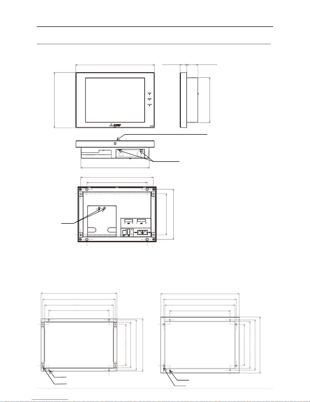
1. External dimens ions
(1) AE-200/AE-50 *1
*1 The dimensions of the AE-200 and AE-50 are the same.
*2 The protrusion when the unit is mounted to a wall or metal control box is 25.0 mm.
*3 A hex key for removing the hex socket bolt is supplied with the AE-200/AE-50 unit.
For how to use it, refer to "IV [1] 4. How to remove and attach the cover."
Mounting plate (supplied)
Used when mounting to a wall or metal control box.
For the mounting procedure, refer to "4-1-2 Wall-embedded installation" in the AE-200/AE-50 Installation Manual.
M4 hex socket bolt (2.5 mm (0.1 in) across flats)*3
40 (1.6)
Bottom hooks
Mounting screws
284 (11)
163 (6.4)
Mounting plate A
Mounting plate B
164 (6.5)
180.4 (7.1)
188.9 (7.4)
148 (5.8)
169.2 (6.7)
180.4 (7.1)
202.1 (8)
217 (8.5)
247 (9.7)
261.2 (10.3)
272.7 (10.7)
282.7 (11.1)
261.2 (10.3)
252.2 (9.9)
217 (8.5)
φ6
φ4
φ6
Unit: mm (in)
25 (0.9)* 2
200 (7.8)
246 (9.6)
261.2 (10.2)
217 (8.5)
180.4 (7.1)
148 (5.8)
φ4
148 (5.8)
Page 30
[IV Product specifications and funct ion s]
26
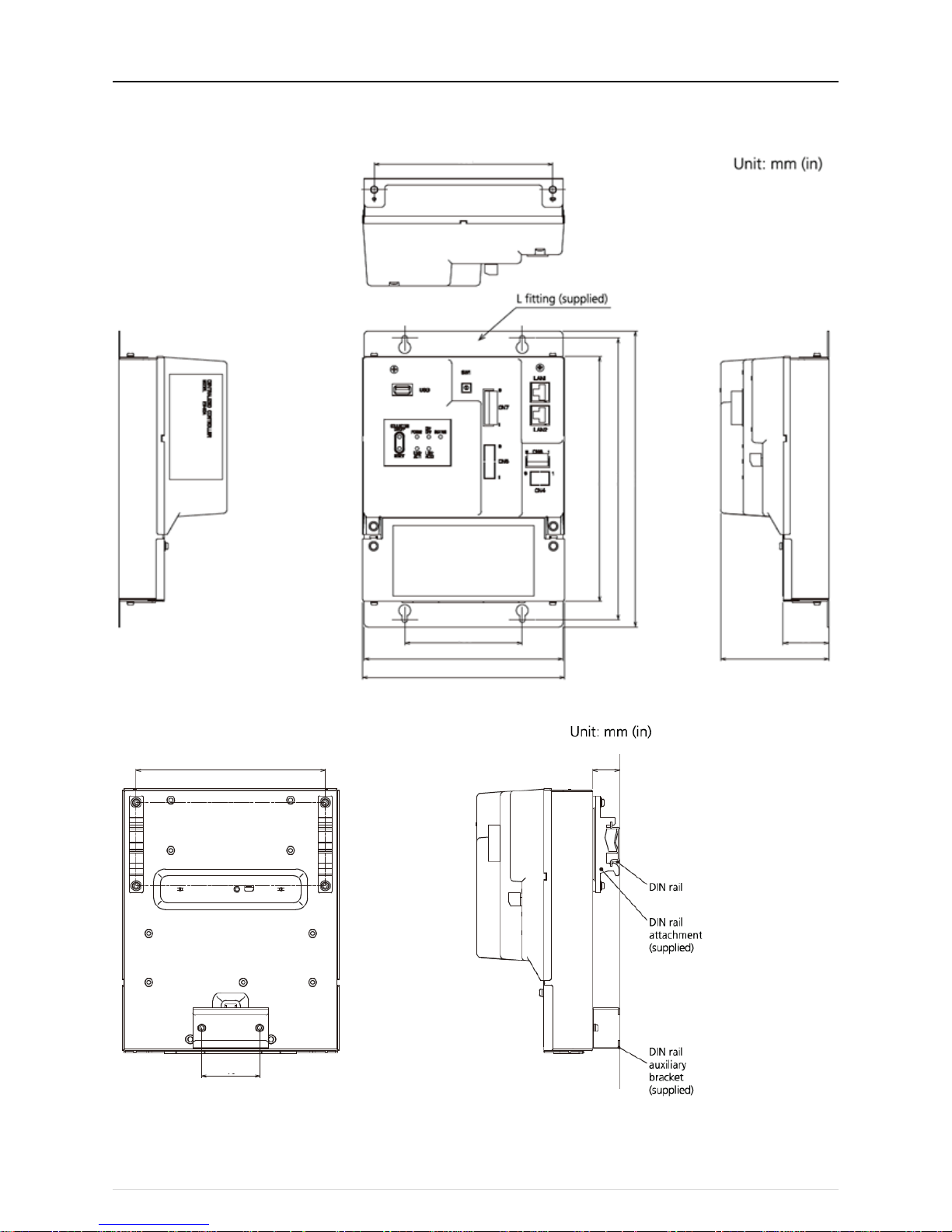
(2) EW-50
When attaching L-fittings
When mounting on DIN rails
* For the installation method, refer to "4. Installation" in the EW-50 Installation and Instructions Manual
152 (6)
100 (3.9)
169 (6.7)
172 (6.8)
209 (8.2)
240 (9.4)
253 (9.7)
38 (1.5)
92 (3.6)
46 (1.8)
150 (5.9)
23 (0.9)
Page 31

[IV Product specifications and function s ]
27
2. Location of main parts
(1) Front of AE-200/AE-50
LED
Description
Power
Lit in green
Power ON
Unlit
Power OF F
LAN1
Blink in orange
Data transmission in progress (LAN1)
LAN2
Planned to be used with BACnet
ON/OFF
Lit in green
One or more air conditioning units are ON.
Blink in green One or more air conditioning units or other related equipment are
in error.
Unlit
All air conditioning units are OFF.
Status
Blink in orange
Error in SD card, or startup failed
Blink in blue
Software update in progress
Blink in pink
Software update failed Item
Description
Reset switch
Used to reboot the AE-200/AE-50.
Collective ON/OFF switch Collectively runs/stops air-conditioning units that have their own
M-NET connected.
The operation becomes the collective stop operation if even one
air-conditioning unit is operating, and the collective run operation if
they are all stopped.
USB port Used when updating the software version, backing up the setting
data, and acquiring billing data.
Model name
Collective ON/OFF switch
Power
LAN1
ON/OFF
Status
Reset switch
Display/touch panel
USB port
for USB
memory
device
LAN2
Decorative cover
* In the case of the AE-50, the model name at the bottom right is "AE-50."
* To remove the decorative cover, you need to remove the hex socket bolt at the bottom.
* If the separately sold cover with a USB door (PAC-YE72CWL) is used, a USB memory device can be connected without
removing the decorative cover.
Page 32

[IV Product specifications and function s ]
28
(2) Back of AE-200/AE-50
Item
Description
LAN1
Connect with other equipment over a LAN via a switching HUB.
LAN2
Planned to be used with BACnet
CN7
Pulse input
Connect the pulse detector of an electricity meter.
CN6
RS-422/485
Unused
CN4
RS-232C
Unused
CN5
External I/O
Cut out the knockout hole and then connect an external I/O adapter (PAC-YG10HA).
TB3 M-NET A, B, S
(M3.5)
M-NET transmission line terminal block
Connect with an outdoor unit using an M-NET transmission line.
(A, B: Non-polarized, S: Shielded)
Ground
(M4)
Connect a ground wire for protection.
CN21 M-NET power jumper Connect the power jumper to supply power to M-NET (default).
If another system controller is connected to the same M-NET, disconnect the power
jumper to supply power to the M-NET from the power supply unit.
TB1 AC power supply
L/L1, N/L2
(M3.5)
Connect an AC power supply cable.
Service cover
* To remove the service cover,
you need to remove the two
fixing screws from the back and
then unhook the hooks at the
bottom.
* When attaching the service
cover, be sure to hook the hooks
before securing the cover with
the two screw s.
Page 33

[IV Product specifications and function s ]
29
(3) Front of EW-50
LED
Description
Power
Lit in green
Power ON
Unlit
Power OF F
ON/OFF
Lit in green
One or more air conditioning units are ON.*1
Blink in green
One or more air conditioning units or other related equipment are in error.
Unlit
All air conditioning units are OFF.*1
Status
Blink in orange
Startup error
Blink in blue
Software update in progress
Blink in pink
Software update failed
LINK/ACT1
Blink in orange
Data transmission in progress (LAN1)
LINK/ACT2
Unused (planned to be used with BACnet)
*1 The statuses of other related equipment are not indicated.
Item
Description
Push switch ON/OFF Collectively runs/stops air-conditioning units that have their own M-NET
connected.
The operation becomes the collective stop operation if even one
air-conditioning unit is operating, and the collective run operation if they are all
stopped.
Reset Used to reboot the EW-50. (This will not affect the operation status of the air
conditioning units.)
USB port
Unused
SW1
Simple address setting
IP addresses can be easily set with SW1.
LAN1
LAN connection
Connects to other units of equipment over the LAN via a HUB.
LAN2
Planned to be used with BACnet
CN7
PI
Connects to metering devices using the supplied connector.
CN6 Unused
CN4 Unused
CN5 External I/O Connects to an external input/output adapter (PAC-YG10HA) by cutting out the
knockout hole.
CN21 M-NET power jumper Connects to the M-NET power jumper to supply power (default).
If another system controller is connected to the same M-NET system and the
equivalent power consumption is 6 or above, disconnect the M-NET pow er
jumper to supply power from the separately-sold power supply unit.
TB3 M-NET A,B,S (M3.5) M-NET transmission terminal block
Connects to M-NET transmission lines from the outdoor unit.
(A, B: Non-polarized, S: Shield)
TB1 Power source AC L/L1, L/L2
(M3.5)
Connects to the power cable.
Ground
(M4)
Connects to the protective ground wire.
Page 34

[IV Product specifications and function s ]
30
3. Electrical wiring diagram
(1) AE-200/AE-50
Board
Code
Name
Board
Code
Name
SUBPWR
TB1 Power terminal block
M-NET
CN5 Connector (external I/O)
TB3 M-NET transmission terminal block CN7 Connector (pulse input)
CN21 Jumper (power supply selector)
CONT
D651 LED (POWER)
F751 Fuse (250 VAC T6.3AH) D652 LED (ON/OFF)
F752 Fuse (250 VAC T2A) D653 LED (STATUS)
MAIN
CN4 Connector (RS-232C) D654 LED (LAN1 LINK/ACT)
CN6 Connector (RS-422/485) D655 LED (LAN2 LINK/ACT)
CN19 Connector (SD card) S651 Reset switch
LAN1 Connector (LAN1) S652 Collective ON/OFF switch
LAN2 Connector (LAN2) USB CN18 Connector (USB)
Page 35

[IV Product specifications and function s ]
31
(2) EW-50
Board
Code
Name
Board
Code
Name
SUBPWR
TB1 Power terminal block
M-NET
CN5 Connector (external I/O)
TB3 M-NET transmission terminal block CN7 Connector (pulse input)
CN21 Jumper (power supply selector) SW1 Switch (IP address setting)
F751 Fuse (250 VAC T6.3AH)
LED
D651 LED (POWER)
F752 Fuse (250 VAC T2A) D652 LED (ON/OFF)
CN4 Connector (RS-232C) D653 LED (STATUS)
MAIN
CN6 Connector (RS-422/485) D654 LED (LAN1 LINK/ACT)
CN19 Connector (SD card) D655 LED (LAN2 LINK/ACT)
LAN1 Connector (LAN1) S651 Reset switch
LAN2 Connector (LAN2) S652 Collective ON/OFF switch
USB CN25 Connector (USB)
Page 36

[IV Product specifications and function s ]
32
4. How to remove and attach the cover
(1) AE-200/AE-50
Item
Work procedure Illustrations
How to remove the
decorative cover
Use the supplied hex key to remove the hex socket bolt
from the bottom of the decorative cover.
How to attach the
decorative cover
Attach the decorative cover to the AE-200/AE-50 unit
and then use the supplied hex key to screw the hex
socket bolt into the bottom of the decorative cover.
How to remove the service cover
[Wiring at the back]
Remove the two fixing screw, lift up the service cover,
and remove the cables from the holes for wiring.
Unhook the bottom hooks from the AE-200/AE-50 unit.
[Wiring at the bottom]
Remove the two fixing screws and unhook the bottom
hooks from the AE-200/AE-50 unit.
・ How to remove the service cover
1. Remove the two fixing screws and lift up the cover.
(Do the same for the wiring at the bottom)
2. Remove the cables from the holes for wiring.
(Only for the wiring at the back)
3. Unhook the bottom hooks from the AE-200/AE-50 unit. (Do
the same for the wiring at the bottom)
How to attach the service cover
[Wiring at the back]
Insert the bottom hooks of the service cover into the
AE-200/AE-50 unit.
Close the cover so that the power supply cable and
M-NET transmission line pass through the holes for the
wiring of the service cover.
Secure the service cover with the two fixing screws.
[Wiring at the bottom]
Check that the power cable and M-NET transmission
line are routed through the knockout holes and
connected to the terminals.
Insert the bottom hooks of the service cover into the
AE-200/AE-50 unit and then secure cover the two fixing
screws.
(Supplied)
Page 37

[IV Product specifications and function s ]
33
(2) EW-50
Item
Work procedure
Illustrations
How to remove the service
cover
Remove the two fixing screw and lift up the service
cover.
How to attach the service cover
Hook the claws at the top of the service cover onto
the EW-50 unit and then secure the cover with the
fixing screws.
Note: When attaching the service cover, take care
that the power supply cable and transmission
line are not trapped between the EW-50 unit
and service cover.
Page 38

[IV Product specifications and function s ]
34
[2] Product specifications of AE-200/AE-50/EW-50
1. Product specifications
(1) Product specifications
The following shows the product specifications of the AE-200/AE-50.
Item
Specifications
Power supply (for
driving unit)
Rated input 100–240 VAC ± 10%; 50/60 Hz Single-phase
Power consumption
12 W
M-NET equivalent power supply No specifications
Only an MN converter can be connected.
Ambient conditions Operating temperature
range
0°C – +40°C (+32°F – +104°F)
Storage temperature
range
-20°C – +60°C (-4°F – +140°F)
Humidity
30%–90% RH (Non-condensing)
Weight
2.3 kg (5-5/64 lbs)
Dimensions (W × H × D) 284 × 200 × 65 mm (11-5/32 × 7-55/64 × 2-17/32 in)
* When installed, AE-200/AE-50 will protrude 25.0 mm (31/32 in) from the
wall or the metal control box.
Installation environment Indoor only
・ For an office environment, install inside a metal control box or similar
environment.
● The above specifications are subject to change without notice for improvement.
The following shows the product specifications of the EW-50.
Item
Specifications
Power supply (for
driving unit)
Rated input 100–240 VAC ± 10%; 50/60 Hz Single-phase
Power consumption
12 W
M-NET equivalent power supply
The equivalent power supply of 1.5
Ambient conditions Operating temperature
range
-10°C – +55°C (14°F – +131°F)
Storage temperature
range
-20°C – +60°C (-4°F – +140°F)
Humidity
30%–90% RH (Non-condensing)
Weight
1.7 kg (4 lbs)
Dimensions (W × H × D) 172 × 209 × 92 mm (6-13/16 × 8-4/16 × 3-10/16 in)
(172 × 253 × 92 mm (10 × 6-13/16 × 3-10/16 in) when using L-fittings)
Installation environment Only in a metal control box indoors
● The above specifications are subject to change without notice for improvement.
Page 39

[IV Product specifications and function s ]
35
(2) Default Settings
The following table lists the default settings of the AE-200/AE-50/EW-50.
Item
AE-200A/AE-50A/EW-50A
AE-200E/AE-50E/EW-50E
Common settings
Date and time settings
April 1, 2014
IP addresses
192.168.1.1
Subnet mask
255.255.255.0
Gateway address
Unset
M-NET address
0
Range of prohibited controllers
SC/RC
External input setting*1
Do not use
External output setting*1
ON/OFF and Error/Normal
Time master setting
Master
Schedule/Season setting
Enabled
Old model compatible mode
OFF
System expansion
Do not expand
AE-200 M-NET *1
Use
AE-200 apportioning *1
Do not use
Occupancy sensor display setting
Show occupancy mark
Brightness sensor display setting
Hide
Date format
dd/mm/yyyy
yyyy/dd/mm
Time format
AM/PM
24-hour display
Unit of temperature display
°F
°C
Room temperature display
*2
Unit of pressure display
PSI
MPa
Humidity display
Display
Maintenance user name
initial
Maintenance user password
init
Administrator user name
administrator
Administrator user password
admin
Unit screen settings
Sound
Level 1
Brightness
100%
Test run
Do not use
Screen lock
Do not use
Administrator user restriction functions
Unit information
Advanced settings
Network settings
Group settings (group configuration)
Interlock LOSSNAY settings
Block settings (block configuration)
Floor layout (floor configuration)
Energy management settings
Peak cut (system configuration)
Web browser settings
List screen group name display
ON
Filter sign display
ON
Administrator user restriction functions
Basic system
Group settings (group configuration)
Interlock LOSSNAY settings
Block settings (block configuration)
Peak cut (system configuration)
Measurement settings
*1 AE-200 only
*2 The settings differ between the LCD screen and the Web browser.
Page 40

[IV Product specifications and function s ]
36
2. AE-200/AE-50/EW-50 unit fu nctio ns and Web browse r func tions
The following table lists the AE-200/AE-50/EW-50 unit functions and Web browser functions.
○: Function available
Item Description
Unit
Web
browser
ON/OFF/Test run
The equipment can be turned on and off and operated per group, per block, or per floor, or
collectively. When the test run mode is selected, the test run operation can be performed. (Unit
screen only)
○ ○
Operation mode
The operation mode can be switched between Cool, Dry, Heat, Fan, and Auto per group, per block,
or per floor, or collectively.
○ ○
Set temperature
The indoor temperature can be set per group, per block, or per floor, or collectively. (0.5°C (1°F)
increments)
Setting temperature range Cool/Dry: 19°C to 35°C (66°F to 95°F) (14°C to 30°C (57°F to 86°F)
when mid temperature model connected)
Heat: 4.5°C – 28°C (40°F – 82°F)
Auto: 19°C to 28°C (66°F to 82°F) (17°C to 28°C (63°F to 82°F)
when mid temperature model connected)
Note: The settable temperature differs depending on the model.
Note: The set temperature may be in 1°C (2°F) increments depending on the model.
Note: The set temperature may be able to be registered for each of the cool and heat
modes depending on the model.
○ ○
Fan speed / Air flow
(LOSSNAY)
*1
The fan speed can be switched to any of four levels per group, per block, or per floor, or collectively.
(There may be no levels, 2 levels, 3 levels, or 4 levels depending on the model, and auto operation is
available for models with an auto function.)
(In the case of LOSSNAY, the fan speed can be switched to Very Low, Low, High, and Auto. The air
flow levels that can be selected differ depending on the model. However, there are the two levels of
Low and High in the case of an interlocked LOSSNAY.)
○ ○
Air flow direction
setting
The air direction setting can be switched to any of five vertical air flow directions, auto, and swing per
group, per block, or per floor, or collectively. (The air flow functions that can be selected differ
depending on the model.)
Operation with five air flow directions and auto is possible only for the models with those functions.
○ ○
Ventilation mode
(LOSSNAY)*1
The ventilation mode can be switched to any of Bypass, Heat Recovery, and Auto per group, per
block, or per floor, or collectively.
○ ○
ON/OFF of interlocked
LOSSNAY*1
When there are interlocked LOSSNAY, they can be switched ON (high/low) or OFF per group or per
block, or collectively.
○ ○
Monitoring of energy
use status*2
The electric energy consumption, outdoor temperature, operation time, and other information can be
displayed and compared in bar graphs and line graphs.
Note: A PI controller and electricity meter (pulse output type) need to be connected to display the
electric energy consumption.
The electric energy consumption cannot be displayed with a PLC for Electric Amount Count
connection.
An AI controller or AHC and a temperature sensor need to be connected for outdoor
temperature display.
○ ○
Ranking*2
The consumption and time can be displayed ranked in order of largest to smallest for electric energy
consumption and fan operation time.
Note: The ranking of electric energy consumption can only be displayed by block.
○ ○
Target value settings*2
The target value for electric energy consumption can be set on an annual, monthly, or weekly basis
and by block.
The set value is displayed in the Energy Use Status screen and the Ranking screen.
○ ○
Peak cut control
status*2
The peak cut control level and electric energy can be displayed.
Note: A license is required.
○ ○
Air-conditioner,
ventilator, and general
equipment schedules
The weekly schedule, annual schedule, and today's schedule for the day-of-week pattern can be set
for each group per group, per block, or per floor, or collectively.
● Up to 24 events can be scheduled for each day, and the "ON/OFF," "Operation Mode," "Set
Temperature," "Air Direction," "Fan Speed," and "Prohibit Local Remote Controller Operation"
settings can be set.
(In the case of LOSSNAY, the "ON/OFF," "Ventilation Mode," and "Air Flow," and "Prohibit Local
Remote Controller Operation" settings can be set for schedule operation.)
● There are five types of weekly schedule, and the season schedule settings can be set.
● The schedule events of the weekly, yearly, or today's schedule are executed on a set day, and
the priority for execution from the highest level to lowest level is [Today] → [Yearly] → [Week 1]
→ ... → [Week 5].
● With the yearly schedule, the days of national holidays and summer holidays and other days
that do not fit in the weekly schedule can be set on 50 days within the range up to 24 months in
the future.
Five operation patterns can be set for each group.
● [Optimized Start] can be set so that the set temperature is reached at the set time. (Indoor units
only)
Note: The items that can be set differ depending on the model (function) of the air conditioner.
○ ○
Page 41

[IV Product specifications and function s ]
37
Item Description
Unit
Web
browser
Enable/disable
schedule
Schedules can be enabled or disabled per group, per block, or per floor, or collectively.
○ ○
Prohibit local remote
controller operation
setting
The items for prohibiting operation from a local remote controller can be selected per group, per
block, or per floor, or collectively. (The items that can be prohibited are ON/OFF, operation mode, set
temperature, filter sign, fan speed, air direction, and timer.)
Note: The items that can be prohibited differ depending on the model of the air conditioner,
LOSSNAY, etc .
○ ○
External input function
settings*3
Emergency stop/normal, emergency stop recover/normal, ON/OFF, prohibit/permit local remote
controller operation, and peak cut level settings be set for all managed air conditioners by inputting a
wet contact signal (12 V DC or 24 V DC) from an external device.
(The PAC-YG10HA external I/O adapter is required separately.)
Note: An external I/O adapter needs to be connected to each AE-200, AE-50, and EW-50.
(An emergency stop of the AE-50 system cannot be performed by an external input to the
AE-200.)
○ ○
External output
function settings*4
The operation signal is output when one or more air-conditioning units are in operation, and the error
signal is output when one or more air-conditioning units are in error (with the exception of the
operation output signal of general equipment (DIDO controller connection), which is output when the
equipment is in error).
(The PAC-YG10HA external I/O adapter is required separately.)
Note: In the case of external output of an error signal with the AE200, an error signal is output
when an error occurs with any of the AE-200, AE-50, and EW-50.
In the case of output of an error signal with the AE-50/EW-50, an error signal is output when
an error occurs with each of the AE-50 and EW-50.
○ ○
Filter sign reset
The filter sign display can be reset per group, per block, or per floor, or collectively.
○
○
Error reset
An error that is currently occurring can be reset.
○
○
Error history reset
The error history (unit errors and communication errors) can be reset.
○ ○
ON/OFF display
(Collective)
The ON/OFF LED of the AE-200/AE-50/EW-50 is on when one or more groups are operating and
off when all groups are stopped (with the exception of general equipment (DIDO controller
connection)).
○
Energy management
table*5
The apportioning results can be displayed using the AE-200 apportioned electricity billing function.
Also, the apportioning results can be output to a USB memory device.
○
Operation status per
group
ON/OFF, operation mode, set temperature, fan speed, air direction, ventilation mode, interlocked
LOSSNAY ON/OFF, schedule operation enabled/disabled, peak cut, and night purge can be
displayed per group
Note: The items that can be displayed differ depending on the models in the group.
○ ○
Filter sign display
The filter sign can be displayed per group, per block, or per floor, or collectively.
○
○
Local remote controller
operation prohibited
display
The items for which operation with a local remote controller is prohibited for this unit or another
system controller are displayed. ○ ○
Display of errors
occurring on
air-conditioning units
The address and error code are displayed for a unit with an error, and the address of the unit that
detected the error is displayed. ○ ○
Monitoring of error
history of
air-conditioning units
Up to 512 errors that occurred in the past are stored. 128 for each AE-200/AE-50/EW-50.
(64 unit errors and 64 communication errors) ○ ○
Error mail send history
The history of mail sent at the time of error occurrence and error recovery can be checked.
○
Monitoring of
measurement status
The measurement values of the temperature sensor and humidity sensor of the AI controller and the
measurement values of the electricity meter, water supply meter, etc. of the PI controller can be
monitored.
○ ○
Refrigerant system
display
A list of refrigerant systems (connection information of outdoor units and indoor units) connected to
the AE-200/AE-50/EW-50 can be displayed.
○
Current date and time
settings
The current date and time can be set.
○ ○
License registration
Purchased licenses can be registered.
○ ○
Page 42

[IV Product specifications and function s ]
38
Item Description
Unit
Web
browser
Unit information
(Basic system)
Items common to the AE-200/AE-50/EW-50 unit and Web browser
The unit name, ID number, whether expand system, date display format, time display format,
temperature display format, room temperature display, pressure display format, and sensor display
format (occupancy, lighting, and humidity) show/hide settings can be set.
AE-200/AE-50 unit only
The display language (Japanese, English, French, German, Spanish, Italian, Russian, Chinese, or
Portuguese) can be changed and the LCD screen brightness, volume, whether test run usable, and
whether screen lock function usable can be set.
Web browser only
The list screen group name display and filter sign show/hide settings can be set.
○ ○
Network settings
The IP address, subnet mask, and gateway settings of the LAN of the AE-200/AE-50/EW-50, the
M-NET address related to M-NET, local remote controller operation prohibited range settings,
external input settings, and external I/O settings can be set.
○ ○
Advanced settings
The time master/sub, ON/OFF of old model compatible mode, and enable/disable of schedule
season settings can be set.
○ ○
Group settings
Register indoor units, LOSSNAY, general equipment, remote controllers, and sub system controllers
to a group.
○ ○
Block settings
Register set groups to a block.
Note: A block that spans AE-200/AE-50/EW-50 systems cannot be set.
○ ○
Interlock LOSSNAY
settings
Register indoor units to interlocked LOSSNAY as interlocking sources.
○ ○
Floor layout settings
The basic floor settings, group display location settings, and floor plan settings can be set.
○
Error mail settings
Various settings such as the e-mail server and error e-mail send address for using error mail
notification can be set.
○
Peak cut control
settings
*2
Settings such as the control system or the control method of indoor units and outdoor units for using
peak cut control can be set. ○ ○
Measurement settings
The settings of the temperature sensor and humidity sensor of the AI controller and the settings of
the electricity meter, water supply meter, etc. of the PI controller can be set.
○ ○
Set temperature range
limit setting
The temperature range of each remote controller can be set for when limiting the operation range of
the set temperature of local remote controllers.
Note: The range for which monitoring operation is possible differs depending on the model. This
cannot be used with A control models (Mr. Slim), room air conditioners, and residential air
conditioners.
○
Energy management
settings*2
The external temperature sensor, apportioning mode, and the electricity meter of the apportioning
source can be set.
○ ○
Night mode schedule
settings
The time period for operation in night mode can be set for when using the night mode (low-noise
operation) of outdoor units.
Note: This cannot be used with Mr. Slim and room air conditioners.
○
Changeover settings
The operation mode (cooling/heating) of all indoor units connected to the same outdoor unit can be
switched based on changes in the room temperature. (Other than the R2 series) The outdoor unit for
which to switch between cooling and heating and the changeover mode (auto/representative group)
can be set.
○
External temperature
interlock control
The external temperature sensor unit can be selected and the control level can be set for each group
for using the external temperature interlock control function.
○ ○
Setback function
Set the control period setting and the upper limit temperature and lower limit temperature for each
group for using the setback function.
○ ○
Interlock control *2
Perform interlock control between connected equipment with interlocking conditions set.
(Up to 150 interlocking conditions can be registered for each AE-200/AE-50/EW-50.)
Note: Interlock control that spans AE-200/AE-50/EW-50 systems cannot be performed.
○
Maintenance user
The maintenance user name and password can be set.
○ ○
Building manager
(administrator user)
The building manager (administrator user) name and password and the available functions can be
set.
○ ○
Data backup
The setting data, user information, and other data can be saved.
○ ○
Data loading
The setting data can be loaded.
○ ○
CSV output
The operation data (charge parameters and power consumption data) for up to 62 days when the
data type is 1-day intervals and up to 4 days when the data type is 30-minute intervals can be saved
to a USB memory device.
○ ○
Energy management
data output
The energy management data can be output.
Note: The data needs to be output from each AE-200/AE-50/EW-50.
○ ○
Page 43

[IV Product specifications and functions]
39
Item Description
Unit
Web
browser
Clear comparison data
*5
If an AE-50, EW-50, or PI controller is replaced when using the apportioned electricity billing function,
clear the comparison data of the AE-50/EW-50 or PI controller.
* Comparison data is the data used to compare the latest values on the AE-50/EW-50 and PI
controller with the values on the AE-200 when the previous apportionment was calculated, and
calculate the increment.
○
Clear carried-over data
*5
When the charge time period settings are changed and a unit price in use is changed to unused,
clear the carried-over data for the unit price that was set to unused.
○
Restore apportioned
data *5
When the AE-200 is replaced, restore the apportioned data from the AE-50/EW-50 to the new
AE-200.
Also, when the AE-50/EW-50 is replaced, restore the apportioned data from the AE-200 to the new
AE-50/EW-50.
○
Touch panel calibration
The touch positions of the touch panel can be calibrated.
○
Software update
The software can be updated by either connecting a USB memory device to the AE-200/AE-50 unit
and then operating the LCD screen or by inserting a CD into a PC and then operating the Web
browser.
○ ○
Group setting
information and
interlocked LOSSNAY
information backup
The group setting information and interlocked LOSSNAY information are retained even if the power
is turned off.
○
Error information
backup
The error history data is retained even if the power is turned off.
○
Schedule settings
backup
The group schedule information set for each group is retained even if the power is turned off.
○
Current date and time
backup
When the power is turned off, the current time is backed up in an internal capacitor for approximately
three days.
(The internal capacitor takes approximately one day to charge. There is no need to replace it.)
○
Lock function
Touch panel operation can be locked to prevent operation until a user name and password are
entered.
○
Touch panel cleaning
The touch panel can be locked and then cleaned.
○
Time management
The clocks on the managed controllers and units are synchronized once a day
(applicable only to controllers and units that support time synchronization).
○
*1 Refers to LOSSNAY and OA Processing unit.
*2 A separate license is required.
*3 The external input function for emergency stop, ON/OFF, and peak cut level cannot be used with general equipment (DIDO
controller connection).
However, emergency stop input can be used by setting the switch settings of the DIDO controller.
*4 The operation status of general equipment (DIDO controller connection) is not output.
*5 This can be used only when using the AE-200 apportioned electricity billing function.
● The above functions vary depending on the equipment connected and the combination of equipment.
● The above functions are subject to change without notice for improvement.
Page 44

[IV Product specifications and function s ]
40
[3] PC operating environment
PC operating environment for Web monitoring
The following environment is required for the PC to monitor and operate air-conditioning units with a Web browser.
Item
Description
CPU
1 GHz or faster
Memory
512 MB or more
Screen resolution
1024 x 768 or higher recommended
Browser Microsoft® Internet Explorer 8.0
Microsoft® Internet Explorer 9.0
Microsoft® Internet Explorer 10.0
Microsoft® Internet Explorer 11.0
* Java runtime environment (Oracle® Java Plug-in) is required.
Operation has been verified with Oracle® Java Plug-in Ver.1.8.0_40.
* The version of the Oracle Java Plug-in can be verified by clicking [Java] in the
Control Panel.
* Install Oracle Java Plug-in that is appropriate for your operating system. When
using an Internet Explorer (64-bit), install a 64-bit Java Plug-in.
On-board LAN port or
LAN card
1 (Must support 100 BASE-TX)
Other Pointing device such as mouse
CD-ROM drive (when using CD)
Page 45

[IV Product specifications and function s ]
41
[4] Various Functions
1. Functions and required equipment and materials
The following table lists the functions supported by the AE-200/AE-50/EW-50 and the products and software required for those
functions.
[Legend] ○: Required
Function
System components
License registration
Other
Centralized controller
Integrated centralized control
software (TG-2000A)
Web
Electric Amount Count
PLC Software
General Control PLC
Software
Demand Input PLC
Software
Other System method
Initial Setting Tool
Charge Calculation Tool
Sequencer (PLC)*1
DIDO controller
PI controller
AI controller
Web browser
○ ○ Personal browser
○ ○ ○ Error mail notification
○ ○ Integrated management (TG-2000A)
○ ○ Yearly/weekly schedule
○
TG-2000A Electric energy charge (electric
energy manual entry method)
○ ○ ○
TG-2000A Electric energy charge (electric
energy metering -device method)
○ ○ ○ ○ ○
TG-2000A Meter charge (electric energy
metering-device method)
○ ○ ○ ○
AE-200 Electric energy charge (electric energy
manual entry method)
○ ○ ○ ○
AE-200 Electric energy charge (electric energy
metering-device method)
○ ○ ○ ○ ○
Operation
and
monitoring of
general
equipment
DIDO controller method
○ ○
Free contact method
○ ○
PLC method
○ ○ ○ ○ ○
Interlocked
control of
general
equipment
DIDO controller method
○ ○ ○ ○
Free contact method
○ ○ ○
PLC method
(between PLC
equipment)
○ ○ ○ ○ ○
PLC method
(between air-conditioning
units and PLC
equipment)
○ ○ ○ ○ ○
Night mode
○
External temperature interlock control
○
○
Night setback function
○
Set temperature range limit setting
○ ○
Temperature and humidity
measurement
○ ○
Upper and lower limit warning mail
○ ○
Energy management function
○ ○
○
Peak cut control
(other system method)
○ ○ ○
Peak cut control (PLC method)
○ ○ ○ ○
Peak cut control (PI controller method)
○ ○ ○ ○
Peak cut control
(Peak cut level contact input)
○ ○
*1 Refers to PLC for Electric Amount Count (PAC-YG11CDA), PLC for General Equipment (PAC-YG21CDA), and PLC for Demand
Input (PAC-YG41CDA).
● The above functions are subject to change without notice for improvement.
Page 46

[IV Product specifications and funct ions]
42
NOTE:
○ About the peak cut function
・ When using the peak cut function, please understand that Mitsubishi Electric cannot compensate for any
damages in the event of electricity consumption exceeding the electricity values of the contract as a result
of a control operation setting mistake, failure of an AE-200/AE-50/EW-50, PLC, PI controller, E-Energy,
or demand controller, or other problem.
・ The peak cut control units are the blocks of indoor units and the outdoor units in the
AE-200/AE-50/EW-50 unit.
・ For the peak cut control for the electricity meter which is performed using the counting function of a PI
controller or PLC, the electricity meter to be monitored by the AE-200/AE-50/EW-50 must be one only,
and it can be set for each AE-200/AE-50/EW-50.
Peak cut control cannot be used with air-conditioning units to be controlled by one AE-200/AE-50/EW-50
in a system with two or more electricity meters connected. Furthermore, use version 1.01 or later of the
Electric Amount Count Software when using a PLC.
・ Peak cut control using a peak cut control device (peak cut level contact input method)
This method directly inputs a peak cut level signal to the AE-200/AE-50/EW-50 via an external input
adapter (PAC-YG10HA).
A PLC is not required for this method. The peak cut level monitoring and control commands can be
issued from up to three AE-200/AE-50/EW-50 in addition to the connected AE-200/AE-50/EW-50.
・ Peak cut control using a peak cut control device (PLC method)
The PLC method sends a peak cut level signal from the demand controller to the AE-200/AE-50/EW-50
via a PLC. Furthermore, PLC software (PAC-YG41/42/43/91/92/93ATM) is required.
Up to 10 AE-200/AE-50/EW-50 units can be set. If the number of AE-200/AE-50/EW-50 exceeds 10,
install multiple PLC.
・ For peak cut control (other system method), up to 10 AE-200/AE-50/EW-50 units can be set.
・ Using a PI controller enables peak cut control from up to three AE-200/AE-50/EW-50 in addition to the
connected AE-200/AE-50/EW-50.
○ About apportioned electricity billing
・ The apportioned electricity billing function of the AE-200 and the apportioned electricity billing function of
the TG-2000A cannot be used at the same time. (Electricity apportioning will no longer be able to be
performed correctly.)
Page 47

[IV Product specifications and function s ]
43
2. Functions and lice nses
Legend ○: License required
● Registration of the license is required for each AE-200/AE-50/EW-50.
● The above functions are subject to change without notice for improvement.
Function
Licenses
License not required
Apportioned electricity billing
Personal Web
Maintenance tool
Energy management license pack
General control PLC
Interlock control
Outdoor unit operation status
monitoring
Super user
Supplementary explanation
Web browser
○
Personal browser
○
Error mail notification
○
Integrated management (TG-2000A)
○
Yearly/weekly schedule
○
TG-2000A Electric energy charge (electric
energy manual entry method)
Method that does not use an electricity meter. TG-2000A is required.
○
TG-2000A Electric energy charge (electric
energy metering -device method)
Method to charge for electric energy used by air conditioner.
TG-2000A is required.
○
TG-2000A Meter charge (electric energy
metering-device method)
Function to charge for outlet and other general electric power, gas,
water, etc. TG-2000A is required.
○
AE-200 Electric energy charge (electric energy
manual entry method)
Method that does not use an electricity meter.
○
AE-200 Electric energy charge (electric energy
metering-device method)
Method to charge for electric energy used by air conditioner.
○
AE-200 Meter charge (electric energy
metering-device method)
Function to charge for outlet and other general electric power, gas,
water, etc.
○
Operation
and
monitoring
of general
equipment
DIDO controller method
○
Free contact method
TG-2000A is required.
○
PLC method
TG-2000A is required.
○
Interlocked
control of
general
equipment
DIDO controller method
When using interlocked control of the AE-200/AE-50/EW-50
○
Free contact method
When using interlocked control of the AE-200/AE-50/EW-50
○
PLC method (between PLC
equipment)
TG-2000A is required.
○
PLC method (between
air-conditioning units and PLC
equipment)
TG-2000A is required.
○
Night mode
○
External temperature interlock control
○
Night setback function
○
Set temperature range limit setting
○
Temperature and humidity measurement
○
Upper and lower limit warning mail
○
Energy management function
○
Peak cut control (other system method)
○
Peak cut control (electric energy amount
monitoring method)
A PI controller is required.
○
Peak cut control
(Peak cut level contact input)
Method to directly input the peak cut level from the demand controller
to the external input of the AE-200/AE-50/EW-50.
○
Peak cut control (PLC method)
Demand Input PLC Software is required.
○
Outdoor unit operation status monitoring
○
Super user
○
Maintenance tool
○
Page 48

[IV Product specifications and function s ]
44
[5] How to check the version of AE-200/AE-50/EW-50
Check the version of AE-200/AE-50/EW-50 in one of the following ways.
Method 1: While the Monitor/Operation screen is displayed on the AE-200/AE-50 unit, press the button at the top right of the
screen to display the Login screen. The version is displayed at the bottom right of the login screen.
Method 2: The software version is displayed on the Registration of Optional Functions screen for the AE-200/AE-50/EW-50 in the
Web browser.
Page 49

[V Troubleshooting]
45
V Troubleshooting
[1] Before performing failure diagnosis ......................................................................................... 46
[2] Error code list ............................................................................................................................ 46
1. List of error codes for errors detected by the AE-200/AE-50/EW-50 ................................. 46
2. Error and preliminary error code list .................................................................................... 47
[3] Troubleshooting and solutions depending on the equipment ................................................. 50
1. How to determine the cause and resolve trouble based on the detected error display
of the AE-200/AE-50/EW-50 ............................................................................................... 50
2. Error judgment based on the STATUS LED display of the AE-200/AE-50/EW-50 .......... 59
3. Troubleshooting depending on the trouble symptoms of the AE-200/AE-50/EW-50
and trouble examples .......................................................................................................... 60
[4] M-NET transmission waveform and noise check procedure .................................................. 69
[5] LAN communication error check procedure ............................................................................ 71
1. About the preliminary check items ...................................................................................... 71
2. About the check method using ping .................................................................................... 74
[6] Peak cut troubleshooting.......................................................................................................... 79
[7] Energy management troubleshooting ..................................................................................... 80
Page 50

[V Troubleshooting]
46
[1] Before performing failure diagnosis
If the AE-200/AE-50/EW-50 is not operating normally, first check the following items.
(The following items are for the maximum system configuration. Just check the items for the applicable equipment.)
No.
Item
Yes
No
1
Are the AE-200/AE-50/EW-50, PC, PLC, HUB, power supply unit, and other equipment and
air-conditioning units powered on?
2
Is a power cable or transmission line disconnected?
3
Is 100 to 240 VAC applied on the AC power cable of the AE-200/AE-50/EW-50?
4
Is 17 to 32 VDC applied on the M -NET transmission line?
5
Have the initial settings been configured for the AE-200/AE-50/EW-50 and each equipment?
6
Are the correct date and time set on the AE-200/AE-50/EW-50?
7
Is the required license number registered for each AE-200/AE-50/EW-50?
8
Is a LAN cable disconnected?
(Are the LAN cables compliant with the relevant standards?)
9
Is the IP address of each equipment set?
10
Is a terminal screws loose or a connector not inserted properly?
If you answered "No" for any of the above items, remove the cause for that item.
If there is no problem, refer to the following sections.
[2] Error code list
1. List of error code s f or er rors dete cted by the A E-200/AE-50/EW-50
The following shows the error codes of errors detected by the AE-200/AE-50/EW-50.
Error code Error description
Unit where error occurred
Outdoor unit
Indoor unit
Remote controller
AE-200
AE-50
EW-50
Remarks
0092
Version combination error
○ AE-200 only
0093
System configuration change warning
○ AE-200 only
0094
“Charge” license not registered
○ AE-200 only
0095
Warning - possibility of damaged metering
device
○ AE-200 only
0097
Apportioned calculation data collection error
○ AE-200 only
6204
External memory read/write error
○
6600
Communication error - Address duplicate
○ ○ ○ ○
6601
Communication error - Polarity unsettled
○
6602
Communication error - Transmission processor
hardwar e error
○
6603
Communication error - Transmission line busy
○
6606
Communication error - Transmission processor
communication error
○
6607
Communication error - No ACK return
○ ○ ○
6608
Communication error - No return of response
frame
○ ○ ○
6920
Communication error - No response
○
7106
System abnormality - Attribute setting error
○
7109
System abnormality - Connection setting error
○
7905
Version error
○
For details on the error codes, refer to "V [3] Troubleshooting and solutions depending on the equipment."
[Supplementary explanation] Error codes 0092 to 0095 and 0097 are for error occurrences of the AE-200 and are stored in the error
history.
Error codes 6607 and 6608 are detected only by the AE-200/AE-50/EW-50 and are for error
occurrences of the AE-200/AE-50/EW-50 and are stored in the error history.
Page 51

[V Troubleshooting]
47
2. Error and preliminary error code list
The following shows the error and preliminary error codes used for air-conditioning systems. Each air-conditioning unit and other
equipment uses some of these error and preliminary error codes.
Error and
preliminary
error codes
Description
Error and
preliminary
error codes
Description
0100
Equipment abnormality
1510
Refrigerant cycle - Gas leakage
01*0
Equipment abnormality (PAC-YG66DCA) in
system *
1511
Refrigerant cycle not operate due to oil slick
abnormality
01**
Equipment abnormality in system **
1512
Refrigerant cycle not operate due to a stop of
freezing protection function
0403
Serial transmission trouble
1513
Refrigerant cycle - Brine freezing
0404
Indoor unit EEPROM error (A)
1559
Oil balance circuit abnormality
0701
Combustion circuit abnormality (A)
2000
Water system abnormality (Pump interlock
abnormality)
0702
Combustion heat exchange overheating
protection (A)
20*0
Water system abnormality in line *
0703
Accidental fire (A)
21**
Water system temperature abnormality - Common
operand: **
0704
Heater abnormality (A)
23**
Water system pressure abnormality - Common
operand: **
0705
Seismoscope malfunction (A)
2500
Water system not operate due to water leak
0706
Flame current sensor abnormality (A)
2501
Water system not operate due to water supply
suspension
0707
Ignition abnormality (A)
2502
Water system not operate due to drain pump
abnormality
0708
Blower motor rotation abnormality (A)
2503
Water system not operate due to drain sensor
abnormality/float switch function
0709
Oil pump circuit abnormality (A)
2504
Water system not operate due to liquid level
abnormality
0900
Test run
2505
Water system not operate due to cool water valve
abnormality
1000
Refrigerant cycle abnormality
2506
Water system not operate due to warm water
valve abnormality
10*0
Refrigerant cycle abnormality in line *
2507
Water system not operate due to dew
condensation prevention control activated
1102
Discharge temperature abnormality (TH4) (A)
2600
Water system operation restricted due to water
leak
1108
Inner thermo (49C) operation (A)
2601
Water system operation restricted due to water
supply suspension/humidifier water supply
suspension
11**
Refrigerant cycle temperature abnormality Common operand: **
2602
Water system operation restricted due to drain
pump abnormality
13**
Refrigerant cycle pressure abnormality - Common
operand: **
2603
Water system operation restricted due to drain
sensor abnormality
1300
Low-pressure abnormality (63L operation) (A)
2604
Water system operation restricted due to liquid
level abnormality
1500
Refrigerant cycle not operate due to overcharge
2613
Drop in water flow rate
1501
Refrigerant cycle not operate due to undercharge
(compressor shell temperature abnormality)
3152
Air system operation restricted due to inverter
control box inner temperature abnormality
1502
Refrigerant cycle not operate due to liquid
back/Low-discharge super heat abnormality (A)
3182
Air system operation restricted due to housing
inner temperature abnormality
1503
Refrigerant cycle not operate due to coil frost
3600
Air system operation restricted due to filter
clogging
1504
Refrigerant cycle not operate due to overheat
protection
3601
Air system operation restricted due to filter
maintenance
1505
Refrigerant cycle not operate due to compressor
vacuum operation protection/refrigerant low
temperature abnormality
3602
Air system operation restricted due to damper
position detecting abnormality
1506
Refrigerant cycle not operate due to refrigerant
pump abnormality
37**
Air system operation humidity abnormality
allowance - Common operand: **
1507
Refrigerant cycle not operate due to composition
detection abnormality
38**
Air system operation humidity abnormality Common operand: **
1508
Refrigerant cycle not operate due to control valve
fault
4000
Electric system abnormality
1509
Refrigerant cycle not operate due to high pressure
abnormality (ball valve closed)
40*0
Electric system abnormality in line *
Page 52

[V Troubleshooting]
48
Error and
preliminary
error codes
Description
Error and
preliminary
error codes
Description
4100
Electric system not operate due to overcurrent
shut-off
426*
Inverter cooling fan trouble - Inverter No.: *
4101
Electric system not operate due to overcurrent
protection
5000
Sensor trouble
4102
Electric system not operate due to open
phase/Open phase (T phase) (A)
50*0
Sensor trouble in system *
4103
Electric system not operate due to reversed
phase/open phase
51**
Temperature sensor trouble - Sensor No.: **
4104
Electric system not operate due to electric leak
5202
Connector (63L) open (A)
4105
Electric system not operate due to short circuit
52**
Pressure sensor trouble - Sensor No.: **
4106
Electric system not operate due to self power
supply OFF/power failure
5300
Current sensor abnormality (A)
4107
Electric system not operate due to overload
53**
Current sensor trouble - Sensor No.: **
4108
Electric system not operate due to overload
protection/OCR51C/Open phase (S phase),51CM
connector open (A)
54**
Humidity sensor trouble - Sensor No.: **
4109
Electric system not operate due to OCR51F
55**
Gas sensor trouble - Sensor No.: **
4110
Electric system not operate due to high voltage
part
56**
Air speed sensor trouble - Sensor No.: **
4111
Electric system not operate due to bus current
57**
Limit switch trouble - Switch No.: **
4112
Electric system not operate due to coil overheat
49°C (120°F)
58**
Sensor trouble - Sensor No.: **
4113
Electric system not operate due to heater overheat
59**
Other sensors trouble - Sensor No.: **
4114
Electric system not operate due to fan controller
abnormality
6000
System abnormality
4115
Electric system not operate due to power supply
synchronism abnormality/Input circuit (board)
failure
6101
System not operate due to abnormality - With
response frame
4116
Electric system not operate due to motor
abnormality/speed abnormality
6102
No answer back
4117
Compressor self-protection function operation (A)
6200
Controller H/W abnormality
4118
Opposite phase detection circuit (board) failure (A)
6201
E2PROM abnormality
4119
Open of 2 or more connectors (A)
6202
RTC abnormality
4121
Electric system not operate due to trouble in
equipment to which a measure against higher
harmonics is taken
6204
External memory read/write error
4123
Electric system not operate due to Inverter output
error
6500
Communication error
4124
Electric system not operate due to damper
abnormality
6600
Communication error - Address duplicate
4125
Electric system - Rush-proof circuit abnormality
6601
Communication error - Polarity unsettled
4200
Inverter abnormality
6602
Communication error - Transmission processor
hardwar e error
420*
Inverter abnormality - Inverter No.: *
6603
Communication error - Transmission line busy
4210
Inverter over curr ent sh ut-off
6604
Communication error - No ACK (06H)
(communication circuit error)
421*
Inverter over curr ent sh ut-off - Inverter No.: *
6605
Communication error - No response frame
4220
Inverter bus voltage insufficiency/Voltage
abnormality (A)
6606
Communication error - Transmission processor
communication error
422*
Inverter bus voltage insufficiency - Inverter No.: *
6607
Communication error - No ACK return
4230
Inverter radiating thermostat abnormality
6608
Communication error - No return of response
frame
423*
Inverter radiating thermostat abnormality - Inverter
No.: *
6800
Communication error - Other communication
errors
4240
Inverter overcurrent (overload) protection
6801
Communication error - V-control communication
error
424*
Inverter over curr ent pr otec tion - Inverter No.: *
6810
Communication error - UR communication error
4250
Inverter IPM/bus voltage abnormality/Power
module abnormality (A)
6811
Communication error - UR communication
synchronism not recover
425*
Inverter IPM abnormality *
6812
Communication error - UR communication
hardwar e error
4260
Inverter cooling fan trouble
6813
Communication error - UR communication status
bit detection error
Page 53

[V Troubleshooting]
49
Error and
preliminary
error codes
Description
Error and
preliminary
error codes
Description
6820
Other communication errors
7105
System abnormality - Address setting over 254
6821
Other communication errors - Transmission line
busy
7106
System abnormality - Attribute setting error
6822
Other communication errors - No communication
ACK
7107
System abnormality - Distributor setting error
6823
Other communication errors - No response
command
7108
System abnormality - Refrigerant system setting
error
6824
Other communication errors - Receive data error
7109
System abnormality - Connection setting error
6830
Communication error - MA communication
refrigerant address double setting error
7110
System abnormality - Refrigerant system
connection/connection data unsettled
6831
Communication error - No MA communication
reception error 7111
System abnormality - I/O connection equipment
not connected/remote controller sensor
abnormality
6832
Communication error - MA communication
synchronism not recover
7112 System abnormality - I/O type setting error
6833
Communication error - MA communication
transmission/reception hardware trouble
7113 System abnormality - Equipment unsettled
6834
Communication error - MA communication start bit
detection error
7116
System abnormality - Replace non-wash setting
error
6840
Communication error - A control no indoor/outdoor
communication/reception abnormality
7117
System abnormality - Model identification setting
error
6841
Communication error - A control indoor/outdoor
communication synchronization recovery
abnormal
7130
System abnormality - Different unit model error
6844
Communication error - A control indoor/outdoor
communication incorrect indoor/outdoor wiring
connection, excessive number of indoor units
(more than five units)
7131
System abnormality - Mixed cooling only H/P
connection error
(Facility PAC)
6845
Communication error - A control indoor/outdoor
communication incorrect indoor/outdoor wiring
connection
(telecommunication, disconnection)
7132
System abnormality - Multiple entries of operation
performance
(Facility PAC)
6846
Communication error - A control indoor/outdoor
communication startup time exceeded
7200
System abnormality - Numeric values unsettled
6920
Communication error - No response
7201
System abnormality - Numeric values unsettled
6922
Communication error – Receiving frame ID error
73**
System abnormality - LON system equipment
abnormality
7000
System abnormality
7901
Maximum connectable No. of units exceeded
7100
System abnormality - Total capacity error
7902
Connection lock error
7101
System abnormality - Capacity code error
7903
Unit information error
7102
System abnormality - Connecting unit number
excess
7904
System setting error
7103
System abnormality - Piping length setting error
7905
Version error
7104
System abnormality - Floor height setting error
NOTE:
○ For the error codes and preliminary error codes used with each air-conditioning unit, refer to the service
handbook for the corresponding air-conditioning unit.
○ The unit error and communication error history can be displayed on the AE-200/AE-50/EW-50 unit LCD and in
a Web browser. The preliminary error history can be monitored with the service LEDs or by connecting
Maintenance Tool to the AE-200/AE-50/EW-50 via the LAN.
Page 54

[V Troubleshooting]
50
[3] Troubleshooting and solutions depending on the equipment
1. How to determine the caus e and res olve tr ouble based on the de tected e rror di spla y of the
AE-200/AE-50/EW-50
The following shows the details, causes, and solutions for the error codes of errors detected at the detection source by the
AE-200/AE-50/EW-50.
First confirm that there is no mistake for each setting.
*
The detection address displayed on the error monitor and in the error history is the address of the controller that detected the error.
Error code
Description and method of
detection
Cause Check procedure and remedy
0092
Version combination error
Error detected when the
versions of the
AE-200/AE-50/EW-50
are not a compatible
combination for the
apportioned electricity
billing function.
1) The apportioned electricity billing
function of the AE-200 has been
enabled but the AE-50/EW-50 is a
version that is not supported (version
earlier than 7.23) by the apportioned
electricity billing function.
The apportioned electricity billing function of
the AE-200 does not operate while this error
code is displayed.
Update the AE-50/EW-50 to Ver.7.23 or
later.
Note: T he equipment recovers from the error
and then data collection resumes after
a maximum of 30 minutes elapse.
For how to update the software, refer to "VIII
[1] AE-200/AE-50/EW-50 update
procedure."
0093
System configuration
change warning
Error detected when the
apportioned data is not
restored when the
AE-200/AE-50/EW-50
is replaced while the
apportioned electricity
billing function of the
AE-200 is enabled.
1) The AE-200 and AE-50/EW-50 back
up each other’s data with the
apportioned electricity billing function
of the AE-200, but the backup data
no longer matches after the
AE-200/AE-50/EW-50 was replaced.
To prevent a loss of backup data, the
apportioned electricity billing function of the
AE-200 does not operate while this error
code is displayed. Perform an apportioned
data restore for the new
AE-200/AE-50/EW-50.
Note: The equipment recovers from the error
and then data collection resumes after
a maximum of 30 minutes elapse.
For how to restore apportioned data, refer to
AE-200 Instruction Book (Apportioned
Electricity Billing Function).
0094
“Charge” license not
registered
Error detected when a
license is not registered to
any of the
AE-200/AE-50/EW-50
while the apportioned
electricity billing function is
enabled for an AE-200
without an apportioned
electricity billing function
license.
1) With the apportioned electricity billing
function of the AE-200, the “Charge”
license needs to be registered to all
the AE-50/EW-50 under the control
of the AE-200, but there is equipment
to which it is not registered.
The apportioned electricity billing function of
the AE-200 does not operate while this error
code is displayed.
Register the “Charge” license to all the
AE-50/EW-50 under the control of the
AE-200.
0095
Warning - possibility of
damaged metering device
Error detected when the
state of the
measurement value of
the meter not counting
up continues for at least
three days even though
the operation amount of
the air-conditioning units
is being counted up
while the apportioned
electricity billing function
of the AE-200 is
enabled.
1) There is a wiring connection failure
between the electricity meter and PI
controller. (When a PI controller is
used)
2) There is a wiring connection failure
between the electricity meter and the
built-in PI of the AE-50/EW-50.
(When meter pulse input (PI) of the
AE-50/EW-50 is used)
3) There is an error with communication
between the PI controller and
AE-50/EW-50.
4) An electricity meter with pulse output
of 10 kWh/pulse or higher is being
used.
5) The carried-over data was not
cleared after the time period of the
unit price was deleted.
Causes 1 to 3) Check the wiring connections
to ensure there is no
connection mistake or
broken/disconnected wire.
Cause 4) If an electricity meter with a large
pulse output such as 10 kWh/pulse
is used, three days or longer may
be required to add one pulse
depending on the operating
conditions of the air-conditioning
units. If changing the pulse output
of the electricity meter is possible,
change it to a value such as 1
kWh/pulse.
Cause 5) Perform the carried-over data
clearing process for the deleted
unit price.
For how to clear the carried-over
data, refer to AE-200 Instruction
Book (Apportioned Electricity
Billing Function).
Note: The equipment recovers from the error
and then data collection resumes after
a maximum of 30 minutes elapse.
Page 55

[V Troubleshooting]
51
Error code
Description and method of
detection
Cause Check procedure and remedy
0097
Apportioned calculation
data collection error
Error detected when an
error with
communication
between the AE-200
and AE-50/EW-50
continues for at least
three days while the
apportioned electricity
billing function of the
AE-200 is enabled.
* When the
communication error
is less than three
days and the
apportioned electricity
billing function of the
AE-200 is disabled,
the error will be 6920.
1) LAN contact failure
2) The power of the HUB is not on.
3) The IP address has not been set.
4) Is the length of the LAN cable 100 m
(328 ft) or less?
5) Is the transmission delay time 4
seconds or less round trip?
Cause 1) Check that the LAN cables
between the
AE-200/AE-50/EW-50 and HUB
are connected.
Cause 2) Check that the power of the HUB
is on.
Cause 3) Check the IP address of the
AE-200/AE-50/EW-50.
Cause 4) Use LAN cables that are 100 m
(328 ft) or less.
Cause 5) Check the communication state by
pinging. For the ping check
method, refer to "V [5] 2. About the
check method using ping." If the
ping is timed out, check the
following.
・ Are LAN cables of category 5 or better
being used?
・ Is there not connections to four or more
layers using a gateway, router, etc.?
6204
External memory
read/write error
Error detected when
writing or reading
to/from the internal SD
card of the
AE-200/AE-50/EW-50
could not be performed
properly.
1) An error occurred because the
reading or writing from/to the internal
SD card could not be performed due
to an unexpected erroneous
operation of the
AE-200/AE-50/EW-50 on which the
error occurred.
2) The internal SD card has come out of
the slot.
3) The AE-200/AE-50/EW-50 has
malfunctioned (circuit failure, etc.).
Shut down the AC power of the
AE-200/AE-50/EW-50 and then turn it back
on and check the STATUS LED.
a) If it is blinking in orange, shut down
the AC power of the
AE-200/AE-50/EW-50 and then
remove the back cover.
Reinsert the SD card, attach the back
cover, and then turn on the AC power
again.
→ If the LED is still blinking in orange,
the AE-200/AE-50/EW-50 has
failed. Replace the
AE-200/AE-50/EW-50.
Note: A commercially available SD
card cannot be used.
b) If the LED is not blinking in orange
but the 6204 error is not resolved, the
AE-200/AE-50/EW-50 has failed.
Replace the AE-200/AE-50/EW-50.
Page 56

[V Troubleshooting]
52
Error code
Description and method of
detection
Cause Check procedure and remedy
When AE-200/AE-50
Remove the four screws in the positions indicated in the figure below, and remove the
back cover.
When you remove the back cover, you will be able to see the SD card.
When EW-50
Remove the four screws in the positions indicated in the figure below, and remove the
back cover.
When you remove the back cover, you will be able to see the SD card.
Note: When attaching the back cover to the AE-200/AE-50 unit, be sure to follow the procedure below.
1. Check that the SD card is inserted properly.
2. Place the back cover on the unit cover so that the right edge (SD card side) of the back cover is
aligned.
3. Move the placed back cover to the left so that it fits to the AE-200/AE-50 unit.
4. Press the top of the back cover to insert the back cover below the claws at the top of the
AE-200/AE-50 unit.
5. Tighten the screws in four places on the back cover.
* When attaching the cover, be very careful not to trap a wire or the SD card.
SD card
SD card
Page 57

[V Troubleshooting]
53
Error
code
Description and method
of detection
Cause Check procedure and remedy
6600
Communication error -
Address duplicate
Error detected when
units with the same
address are
transmitting.
1) There are two more units with the same
address among the
AE-200/AE-50/EW-50, outdoor units,
indoor units, LOSSNAY, M-NET
remote controllers, and other units.
2) Two or more AE-200/AE-50/EW-50
with the same address set are installed
in the same transmission line system.
<Example> The part in ( ) indicates the
detection source.
000-6600(000)
There are two or more controllers with
the address "000".
3) The transmitted data changed due to
noise during transmission.
4) While AE-200 M-NET is set to [Do not
use], the power jumper (CN21) of the
AE-200 was removed.
Causes 1) and 2) Find the unit that has the same
address as the unit where the
error occurred.
Cause 3) Check the transmission waveform and
noise on the transmission line. For the
check procedure, refer to "V [4] M-NET
transmission waveform and noise
check procedure."
Cause 4) Check the connection of the power
jumper of the AE-200. Be sure to
connect the power jumper even when
AE-200 M-NET is set to [Do not use].
6601
Communication error -
Polarity unsettled
1. Error detected
when the
transmission
processor which is
an M-NET
communication
component cannot
verify the + and voltage polarity of
the M-NET
transmission line.
1) There is no voltage between the M-NET
transmission line connected to the
AE-200/AE-50/EW-50.
2) The M-NET transmission line
connected to the AE-200/AE-50/EW-50
is shorted.
3) The M-NET power supply is duplex
feeding and has a different polarity
connection.
Causes 1) and 2)
Check whether there is a voltage to the M-NET
transmission line of the AE-200/AE-50/EW-50
and fix any wiring work mistakes.
In the case of a system for which power is
supplied from the AE-200/AE-50/EW-50 to the
MN converter, check that the M-NET power
jumper (CN21) is connected.
Cause 3) Check whether power is being supplied
to the M-NET transmission line from
multiple equipment, and fix the power
supply configuration if it is incorrect.
2. Detected invalid
signal due to a
transmission
waveform error or
noise on the
M-NET
transmission line.
4) Contact failure of the transmission line
of an outdoor unit or indoor unit.
5) Attenuation of the transmission
voltage/signal because the allowable
range for the transmission line wiring
has been exceeded.
・ Farthest end: Exceeds 200 m (656 ft)
・ Remote controller line: Exceeds 10 m
(32 ft)
However, there is no problem if the
portion where the remote controller line
exceeds 10 m (32 ft) is 1.25 mm
2
.
6) Attenuation of the transmission
voltage/signal because mismatch of
transmission line types
Wire diameter: Less than 1.25 mm
2
7) The M-NET power supply is duplex
feeding and has a same polarity
connection.
8) Failure of control board in the outdoor
unit
Causes 4) to 8)
→ If you find the cause, fix the problem.
→ If you cannot find the cause, check the
transmission waveform and noise on the
transmission line.
Perform the check procedure in accordance
with "V [4] M-NET transmission waveform and
noise check procedure" and <Transmission
waveform and noise check procedure> in the
Service Handbook of the air-conditioning unit.
The part causing the error may be a different
line than the one where the error was detected
so check all wiring in the same system.
3. Polarity not set error
9) Defective AHC ADAPTER
Check the voltage and short circuit.
Replace the product.
If the same address could be verified, check
whether there are any mistakes with the wiring
and whether there are any mistakes with the
addresses in the system, and fix any mistakes
you find.
Turn off the power of the air-conditioning units,
controllers, and other equipment at the same
time, leave it off for at least 5 minutes, and then
turn it back on.
CN21
Page 58

[V Troubleshooting]
54
Error
code
Description and method
of detection
Cause Check procedure and remedy
6602
Communication error -
Transmission processor
hardwar e error
The transmission
processor intended to
send "0" but "1" is
output on the
transmission line.
Cause 1) When work was performed or the polarity was changed for the transmission line of either
an indoor unit or outdoor unit while the power was left on, the waveform changed and an
error was detected when the transmission data collided.
Cause 2) When a 100 V power supply was connected to the indoor unit.
Cause 3) Ground fault of the transmission line.
Cause 4) When a power supply unit for the transmission line is not used in a system with the
AE-200/AE-50/EW-50 connected, the power jumper is inserted in CN40 on multiple
outdoor units.
Cause 5) When a power supply unit for the transmission line is used in a system with the
AE-200/AE-50/EW-50 connected, the power jumper is inserted in CN40 on one of the
outdoor units.
Cause 6) Failure of the controller on which the error occurred.
Cause 7) When the transmitted data changed due to noise during transmission.
Cause 8) Defective AHC ADAPTER
Refer to the CITY MULTI (Outdoor Unit) Service Handbook.
6603
Communication error -
Transmission line busy
1. Collision over error.
Error when the state
of data not being able
to be transmitted
continues for a period
of 4 to 10 minutes due
to a transmission
collision.
2. Error when the state
of data not being
output to the
transmission line
continues for a period
of 4 to 10 minutes due
to, for example, noise.
1) The transmission processor is in the
state of being unable to transmit due to
a voltage of a short period such as
noise continuing to be generated and
causing an interference on the
transmission line.
2) Failure of controller on which error
occurred.
3) Defective AHC ADAPTER
Check the transmission waveform and noise on
the transmission line. Perform the check in
accordance with <Transmission waveform and
noise check procedure>.
→ If there is no noise, the controller at the
source of occurrence has failed.
If the AE-200/AE-50/EW-50 has failed,
replace the AE-200/AE-50/EW-50.
→ If there is noise, refer to "V [4] M-NET
transmission waveform and noise check
procedure."
Refer to the CITY MULTI (Outdoor Unit) Service
Handbook.
Page 59

[V Troubleshooting]
55
Error
code
Description and method
of detection
Cause Check procedure and remedy
6604
M-NET communication
error - No ACK return
Error detected by
AHC ADAPTER wh en
the other party fails to
return the ACK signal
after a command
transmission on
M-NET.
1) Incorrect initial settings
2) The address of the other party on the
M-NET transmission line changed
during transmission.
3) Defective M-NET transmission line
4) Transmission line or connector
disconnected at the address of the
other party in M-NET communications.
5) Other party in M-NET communications
is effective
6) For communications about multiple
refrigerants, the transmission line or
connector is disconnected from the
terminal block for centralized control
(TB7).
7) For communications about multiple
refrigerants, power is cut to an outdoor
unit.
8) For communications about multiple
refrigerants, the power connector
(CN40) was not inserted in an outdoor
unit.
9) For communications about multiple
refrigerants, two or more power
connectors (CN40) were inserted for
centralized control.
10) For communications about multiple
refrigerants, an outdoor unit power
supply system is defective.
11) Transmitted data changed due to noise
on the M-NET transmission line.
An AHC ADAPTER No ACK ret urn error was
displayed on the remote controller or centralized
controller.
Follow the procedure below to determine the
address of the unit that caused the AHC
ADAPTER error.
(1) Use the centralized controller or Maintenance
Tool to check for abnormalities in the I/O data
held in Mitsubishi air conditioners set by the
initial settings.
(No value is displayed when data is abnormal.)
→ If an abnormality exists, check for problems
in the unit at the address where the
corresponding data is held and for problems
in the M-NET transmission line connected to
the unit or in the unit itself. (For
communications about multiple refrigerants,
also investigate intermediate outdoor units.)
(2) Check for incorrect remote controller or
centralized controller settings that do not
correspond to (1) above.
→ If incorrect settings are discovered at steps
(1) or (2), use Maintenance Tool to repeat
the initial settings.
If the cause does not correspond to steps (1) or
(2), check for noise in the M-NET transmission
line.
6605
M-NET communication
error - No return of
response frame
Error indicating that
the ACK signal was
returned to
acknowledge receipt
but no response was
returned when a
communication
command was sent
over M-NET.
1) Transmission line work was performed
while power is supplied to M-NET.
2) Transmitted data changed due to noise
on the M-NET transmission line.
3) Transmission line voltage/signal
attenuation as M-Net transmission line
exceeded its permitted length range.
Remote end: 200 m max.
4) Transmission line voltage/signal
attenuation due to mismatch in M-Net
transmission line types.
Cable cross-sectional area: 1.25 mm
2
min.
Cut the power supply from the unit (outdoor unit or
power supply unit) that supplies power to AHC
ADAPTER, or reset the error from the remote
controller or centralized controller.
→ If the same error recurs, see causes 3) and 4).
→ If causes 3) and 4) do not apply, check the
transmission waveform and noise in the
transmission line. For details about the check
procedures, refer to the CITY MULTI (Outdoor
Unit) Service Handbook.
6606
Communication error -
Transmission processor
communication error
Failure with
communication
between the device
processor on the
board and the
transmission
processor.
1) Error that occurs when data was not
transmitted normally due to an
unexpected erroneous operation of the
controller on which the error occurred.
2) Failure of the controller on which the
error occurred.
3) Error due to abnormal data
transmission due to a chance
malfunction of the AHC ADAPTER.
4) Defective AHC ADAPTER
Causes 1) and 2)
Shut off the AC power of the
AE-200/AE-50/EW-50 and then turn it back on.
→ If the same error occurs again, the controller
on which error occurred has failed.
If the AE-200/AE-50/EW-50 has failed,
replace the AE-200/AE-50/EW-50.
Causes 3) and 4)
Cut the power supply from the unit (outdoor unit or
power supply unit) that supplies power to AHC
ADAPTER, or reset the error from the remote
controller or centralized controller.
→ If the same error recurs, AHC ADAPTER is
defective.
Page 60

[V Troubleshooting]
56
Error
code
Description and method
of detection
Cause Check procedure and remedy
6607
Communication error -
No ACK return
Error detected by the
controller on the
transmission side
when there is no reply
(ACK signal) from the
other party after
transmission.
1) The transmission line of the centralized
control terminal block (TB7) of the outdoor
unit is disconnected or shorted.
2) Power of the outdoor unit is shut off.
3) The electric system of the outdoor unit has
failed.
4) When the address of the outdoor unit
changes or is changed part way through
or when the error occurred after normal
operation was performed once, there are
the following causes.
・ System abnormality - Total capacity error (7100)
・ System abnormality - Capacity code error (7101)
・ System abnormality - Connecting unit number
excess (7102)
・ System abnormality - Address setting over 254
(7105)
a) Check causes 1) to 4).
Fix the problem if you find the cause, and
proceed to b) if you do not find the cause.
b) Shut off the power of the
AE-200/AE-50/EW-50 and then turn it back
on.
Fix the problem if you find the cause, and
proceed to c) if you do not find the cause.
c) Check whether or not an error has occurred
by checking the remote controller or the LED
for failure diagnosis on the outdoor unit.
When there is an error
→ Fix the failed part in accordance with the
details on the error code.
a) Error for only some indoor units.
1) When the address of the indoor unit
changes or is changed part way
through.
2) The transmission line of the indoor unit
is defective or disconnected.
3) The connector (CN2M) of the indoor
unit is disconnected.
4) The indoor unit controller has failed.
Turn off the power of the outdoor units and indoor
units at the same time, leave it off for at least 5
minutes, and then turn it back on. Shut off the
power of the AE-200/AE-50/EW-50 and then turn
it back on.
The equipment recovers normally if an
unexpected error occurred. If it does not recover
normally, check causes 1) to 4).
b) All indoor units in one refrigerant system
are in error
5) Outdoor unit detects the error.
・ System abnormality - Total capacity error (7100)
・ System abnormality - Capacity code error (7101)
・ System abnormality - Connecting unit number
excess (7102)
・ System abnormality - Address setting over 254
(7105)
6) The transmission line of the
centralized control terminal block
(TB7) of the outdoor unit is
disconnected or shorted.
7) Power of the outdoor unit is shut off.
8) The electric system of the outdoor unit
has failed.
9) The address switch of the outdoor unit
is mistakenly set to 000 (00).
a) Check the failure diagnosis LED on the
outdoor unit.
→ When an error is occurring, perform a
check in accordance with the details on
the error code.
→ When an error is not occurring, proceed to
b)
b) Check the details of causes 6) to 9).
c) All indoor units are in error
10) When a power supply unit for the
transmission line is used, the power
jumper (CN40) is inserted for
supplying power to the centralized
control transmission line of the
outdoor unit.
11) When outdoor units are used, the
power jumper (CN40) is inserted for
supplying power to the centralized
control transmission line of multiple
outdoor units.
12) The transmission line power supply
unit is disconnected or the power is
shut off.
13) The AE-200/AE-50/EW-50 has failed.
Check the voltage of the centralized control
transmission line. (Voltage between A and B of
TB3 in the case of the AE-200/AE-50/EW-50)
・ When 17 V or higher
→ Check causes 5) to 11)
・ When less than 17 V
→ Check cause 12)
* Same as when the occurrence source is an indoor unit (Read that section and replace the term
"indoor unit" with "remote controller" or "system remote controller")
* If recovery from the
error is not possible with
this check method and
solution, refer to the
service manual of the
air-conditioning unit.
Occurrence source address: Remote controller
Occurrence source address: System remote con troller
Occurrence source address: Indoor unit
Occurrence source address: Outdoor unit
Page 61

[V Troubleshooting]
57
Error
code
Description and method
of detection
Cause Check procedure and remedy
Communication error -
No ACK return
Error detected by the
controller on the
transmission side
when there is no reply
(ACK signal) from the
other party after
transmission.
An address that does not exist is set in the
group registration, interlock LOSSNAY
settings, or measurement settings of the
AE-200/AE-50/EW-50.
Check whether the address that does not exist in
the system configuration is set in the group
registration, interlock LOSSNAY settings, or
measurement settings.
If it is set, delete it.
6608
Communication error -
No return of response
frame
When transmission
was performed, there
was an
acknowledgment
(ACK) to notify that the
transmission was
received from the
other party but the
response command
was not returned.
The transmission side
detects an error 10
consecutive times at
3-second intervals.
1) When work was performed or the
polarity was changed for the
transmission line while the power was
left on, the waveform changed and an
error was detected when the
transmission data collided.
2) Transmission fails repeatedly because
of, for example, noise.
3) Attenuation of the transmission line
voltage/signal because the allowable
range for the transmission line wiring
has been exceeded.
・ Farthest end: 200 m (656 ft) or less
・ Remote controller line: 10 m (32 ft)
or less
4) Attenuation of the transmission
voltage/signal because mismatch of
transmission line types.
・ Wire diameter: 1.25 mm
2
or more
5) The set temperature range limit is set in
a system with a remote controller that
does not support the set temperature
range limit connected.
a) When occurs during test run
Turn off the power of the outdoor units, indoor
units, and LOSSNAY at the same time, leave
it off for at least 5 minutes, and then turn it
back on.
→ If the equipment recovers from the error
normally, the error was detected because
transmission work was performed while
the power was on.
→ If the error occurs again, proceed to b).
b) Check causes 3) and 4).
→ If you find the cause, fix the problem.
→ If you do not find the cause, proceed to c).
c) Check the transmission waveform and noise
on the transmission line. Perform the check
in accordance with <Transmission waveform
and noise check procedure>.
d) If the cause is not any of 1) to 4), check the
system operating status and configuration.
→ If you find the cause, reset the remote
controller.
6920
Communication error -
No return of response
frame
1) LAN contact failure.
2) The power of the HUB is not on.
3) The IP address has not been set.
4) Is the length of the LAN cable 100 m
(328 ft) or less?
5) Is the transmission delay time 4
seconds or less round trip?
Cause 1) Check that the LAN cables between the
AE-200/AE-50/EW-50 and HUB are
connected.
Cause 2) Check that the power of the HUB is on.
Cause 3) Check the IP address of the
AE-200/AE-50/EW-50.
Cause 5) Check the communication state by
pinging.
For the ping check method, refer to "V [5]
2. About the check method using ping."
If the ping is timed out, check the
following.
・ Are LAN cables of category 5 or better being
used?
・ Is there not connections to four or more layers
using a gateway, router, etc.?
7106
System abnormality -
Attribute setting error
1) A unit with a different attribute
(air-conditioning unit or other unit) is set
for the address for which the PI
controller or other device should be set.
2) The unit address set for the interlock
source in the interlock LOSSNAY
settings is not a LOSSNAY.
3) The attribute (IC/FU) setting of the OA
Processing unit is not correct.
Cause 1) In the case of AE-200/EW-50, change
the setting address of the PI controller,
etc. to the correct address. Alternatively,
delete it.
Cause 2) Change the address set for the interlock
source in the interlock LOSSNAY
settings to the correct address.
Alternatively, delete it.
Cause 3) Switch the attribute with the dip switch.
For details, refer to the installation
manual for OA Processing unit.
If 6608 is occurring, it is very likely
to be due to noise.
Address that should not exist
Page 62

[V Troubleshooting]
58
Error
code
Description and method
of detection
Cause Check procedure and remedy
7130
System abnormality -
Different unit model error
ALPHA2 program
version mismatch error
1) The ALPHA2 program was created and
run without using the base program
supplied with AHC ADAPTER.
2) Version data has been overwritten in
the base program supplied with AHC
ADAPTER.
3) The ALPHA2 base program used did
not correspond to the AHC ADAPTER
version.
Causes 1) and 2)
Confirm that the ALPHA2 internal program uses
the base program supplied with AHC ADAPTER.
Check that the program version number matches
the base program version number.
=> If not, recreate the ALPHA2 program from
scratch using the base program supplied with
AHC ADAPTER.
Cause 3) (N/A as of April 2013)
7905
Version error
PAC-YG50ECA is connected.
Disconnect PAC-YG50ECA from the system.
If an expansion controller is required, use the
AE-50/EW-50.
NOTE:
When the error code is for a detection source other than AE-200/AE-50/EW-50, refer to the service handbook
or each air-conditioning unit and perform the checks and take the corresponding measures.
Page 63

[V Troubleshooting]
59
2. Error judgment based o n the STA TUS LED di splay of the A E-200/AE-50/EW-50
The AE-200/AE-50/EW-50 indicates its internal status with the STATUS LED.
The following table shows the LED lighting states, operating status, check methods, and solutions.
STATUS LED
(Lighting color and
state)
Operation status Cause Check procedure and remedy
Off Normal
The equipment is operating
normally.
-
-
Blinking in
blue
Normal
The software of the
AE-200/AE-50/EW-50 unit is
being updated.
-
The LED will turn off after the update
completes. Please wait until the
process completes.
Blinking in pink
Error
The software update of the
AE-200/AE-50/EW-50 unit
failed.
1) An error occurred because the
update process could not be
performed normally due an
unexpected erroneous operation.
2) The update file is incorrect.
3) The USB memory device is not
inserted properly.
4) The USB memory device is not
compatible with the
AE-200/AE-50/EW-50.
5) The USB memory device is
damaged.
6) The USB memory device was
removed and then reinserted within
a short period of time.
7) The AE-200/AE-50/EW-50 has
failed.
1) Perform the update again.
2) Check the file.
Has the software for the AE-200,
AE-50, and EW-50 been mixed
up?
3) Check that the USB memory
device is inserted properly.
4) Refer to "III [9] (2) About USB
memory devices."
5) Connect the USB memory device
to a PC or other device and check
that the data inside it can be read
correctly.
6) Reset the power of the AE-200,
AE-50, and EW-50 and t hen
perform the update again.
7) If the update fails after resetting
the power, the product is likely to
have failed so replace it.
1) An error occurred because the
update process could not be
performed normally due an
unexpected erroneous operation.
2) The update file is incorrect.
3) The AE-200/AE-50/EW-50 has
failed.
1) Check that the LAN cable is
connected properly and then
perform the update again.
2) Check the file.
Has the software for the AE-200,
AE-50, and EW-50 been mixed
up?
3) If the update fails after resetting
the power, the product is likely to
have failed so replace it.
Blinking in orange
Error
The LED blinks in orange
after the power is turned on
and then a unit reset is
performed 30 minutes after
the power was turned on.
1) An error occurred because the
reading or writing from/to the
internal SD card could not be
performed due to an unexpected
erroneous operation.
2) The internal SD card has come out
of the slot.
3) The AE-200/AE-50/EW-50 has
failed. (Memory circuit failure, etc.)
The LED is blinking in orange and the
[6204] error is also detected.
Check causes 1) and 2).
Check how to perform the procedure
to resolve the problem of error code
[6204] in "V [3] 1" and then resolve
the problem.
→ If the LED is still blinking in
orange after taking the measure,
the AE-200/AE-50/EW-50 has
malfunctioned. Replace the
AE-200/AE-50/EW-50.
The unit does not start up.
(A reset is not performed.)
1) A normal startup was not possible
due to an unexpected erroneous
operation of the controller on which
the error occurred.
2) The AE-200/AE-50/EW-50 has
failed.
1) Shut down the power of the
AE-200/AE-50/EW-50 and then
turn it back on.
→ If the unit still does not start up
after taking the measure, the
AE-200/AE-50/EW-50 has
malfunctioned. Replace the
AE-200/AE-50/EW-50.
When updating the software using a
USB memory device
When updating via the Web
Reading from the SD card failed.
Startup error
Page 64

[V Troubleshooting]
60
3. Troubleshooti ng dep endin g on the tr ouble symptom s of the AE-200/AE-50/EW-50 and trouble exa mples
(1) When AE-200/AE-50/EW-50 unit functions
Symptom
Cause
Check procedure and remedy
1
The LCD remains off and no
operation is possible.
1) AC power is not being
supplied.
2) The AE-200/AE-50 has failed.
(Internal power supply failure,
etc.)
Cause 1) Check the voltage of the AC power supply terminal
block of the AE-200/AE-50.
a) When 0 V
→ Check whether the circuit breaker connected to
the AC power supply is ON.
b) When 100 to 240 VAC
→ Proceed to cause 2)
Cause 2) Shut off the AC power of the AE-200/AE-50 and
then turn it back on.
→ If the same error occurs again, the AE-200/AE-50
has failed. Replace the AE-200/AE-50.
2
The LCD screen turns on
and off every few seconds
and normal startup is not
possible.
1) A software update of the
AE-200/AE-50 did not end
normally.
2) The AE-200/AE-50 has failed.
(Internal connector contact
failure, etc.)
Cause 1) Check the STATUS LED.
→ If it is blinking in pink, perform the software update
again. Refer to "VIII [1] AE-200/AE-50/EW-50
update procedure."
Cause 2) If the cause is not cause 1) above, shut off the
power and then turn it back on. If the same
symptoms occur, the AE-200/AE-50 has failed.
Replace the AE-200/AE-50.
3
The LCD screen becomes
red and a restart is
performed repeatedly.
The AE-200/AE-50 has failed.
(SDRAM failure, etc.)
The AE-200/AE-50 has failed. Replace the AE-200/AE-50.
4
Prohibiting operation with
the local remote controller
does not work.
The M-NET remote controller is not
registered to the group of the
AE-200/AE-50/EW-50.
Check whether the M-NET remote controller is registered to
the group on the AE-200/AE-50/EW-50, and if it is not,
perform group registration for the M-NET remote controller.
5
The time is significantly
different from the set time.
1) Incorrect setting from upper
level equipment.
2) The AE-200/AE-50/EW-50 has
failed.
Cause 1) Check the upper level equipment (TG-2000A, etc.)
to see whether there is equipment for which the time
is wrong.
[Supplementary explanation]
If the cause is not incorrect setting from upper level
equipment, disconnect from the LAN and leave the
equipment for one hour without a connection to the LAN and
then check.
→ If the time is significantly slow (10 seconds or more per
hour), the AE-200/AE-50/EW-50 has failed. Replace the
AE-200/AE-50/EW-50.
6
Error output of the external
output always continues to
be ON even though an error
has not been detected.
1) The power supply of the
external circuit is connected
with the polarity reversed.
2) AC power is applied to the
external input.
3) The AE-200/AE-50/EW-50 has
failed.
Cause 1) Check the polarity of the connection of the external
power supply of the external circuit.
If it is reversed, fix the polarity. If output is not normal
even after changing the polarity, replace the
AE-200/AE-50/EW-50.
Cause 2) ad 3) Replace the AE-200/AE-50/EW-50.
7
The unit icon remains in the
starting up state and does
not change.
A communication error is occurring.
The startup process will complete approximately five minutes
after the power is turned on.
After that, check the error code and remove the cause of the
communication error. For the error codes detected by the
centralized controller, refer to "V [3] 1. How to determine the
cause and resolve trouble based on the detected error display
of the AE-200/AE-50/EW-50."
Page 65

[V Troubleshooting]
61
Symptom
Cause
Check procedure and remedy
8
The initial settings data
cannot be output to a USB
memory device.
1) The USB memory device is not
inserted properly.
2) There is no free space in the
USB memory device.
3) The USB memory device is not
supported by the
AE-200/AE-50.
4) The USB memory device is
damaged.
5) The USB memory device was
removed and then reinserted
within a short period of time.
6) The AE-200/AE-50 has failed.
Check causes 1) to 5). Take the measure corresponding to
the cause.
Cause 1) Check that the USB memory device is inserted
properly.
Cause 2) Check that there is free space on the USB
memory device and free up space if necessary.
(Minimum of 64 MB)
Cause 3) Refer to "III [9] (2) About USB memory devices."
Cause 4) Try using another USB memory device.
Cause 5) Restart the AE-200/AE-50 (power OFF → ON).
If the cause of the problem was none of causes 1) to 5), the
AE-200/AE-50 has failed. Replace the AE-200/AE-50.
9
The charge parameters
cannot be output to a USB
memory device.
1) The USB memory device is not
inserted properly.
2) There is no free space in the
USB memory device.
3) The USB memory device is not
supported by the
AE-200/AE-50.
4) The USB memory device is
damaged.
5) The USB memory device was
removed and then reinserted
within a short period of time.
6) The “Charge” license is not
registered.
7) The AE-200/AE-50 has failed.
Check causes 1) to 6). Take the measure corresponding to
the cause.
For causes 1) to 5), check causes 1) to 5) for the item above.
Cause 6) Check whether the apportioned electricity billing
license is valid, and if it is invalid, register a
license.
If the cause of the problem was none of causes 1) to 6),
replace the AE-200/AE-50.
10
The date and time of the
AE-200/AE-50/EW-50 are a
date and time in the past.
1) The date and time were not set
after installation.
2) If the power of the
AE-200/AE-50/EW-50 is turned
off after the power has been off
for at least one week, the date
and time will not have been
retained.
3) An AE-200/AE-50/EW-50 was
added to the system but its
time was not set.
Cause 1) Set the current date and time on the date and
time setting screen.
Cause 2) When the power remains off for about one week,
the date is returned to April 1, 2014.
(Supplementary explanation) The billing results will be
affected in a system with a billing function, so set the current
date and time on the date and time setting screen. If there
is a
TG-2000A, set the date and time on the TG-2000A.
Cause 3) The date at the initial startup becomes April 1,
2014. Set the current date and time on the date
and time setting screen.
11
A place that differs from the
touched position responds.
1) You are not pressing firmly
enough.
2) There is an offset due to the
viewing angle.
3) The AE-200/AE-50 has failed.
(Touch panel input circuit
failure, etc.)
Causes 1) and 2) If a place that differs from the touched
position responds, perform touch panel
position adjustment on the calibration screen.
(Supplementary explanation) The calibration screen can be
opened from [Initial Settings] → [Maintenance] →
[Touch Panel Calibration].
→ If touch panel position adjustment is not
successful, the AE-200/AE-50 has failed. Replace
the AE-200/AE-50.
Page 66

[V Troubleshooting]
62
Symptom
Cause
Check procedure and remedy
12
A floor plan cannot be read.
1) The USB memory device is not
inserted properly.
2) A USB memory device that is
supported by the
AE-200/AE-50 is not being
used.
3) The name of a file you are
attempting to read is incorrect.
4) There are no files in the correct
location in the USB memory
device.
5) The created gif files contain
extension data (XMP, etc.).
6) The file size is not correct.
7) The USB memory device is
damaged.
8) The USB memory device was
removed and then reinserted
within a short period of time.
9) The AE-200/AE-50 has failed.
Check causes 1) to 8). Take the measure corresponding to
the cause.
Cause 1) Check that the USB memory device is inserted
properly.
Cause 2) Refer to "III [9] (2) About USB memory devices."
Cause 3) Set a correct file name as described in the
instruction manual.
E.g.: floor_01.gif
If [Hide extensions for known file types] is set in
the folder settings of the PC on which the file was
created, check the file name in the properties.
Cause 4) Place the files in the root directory of the USB
memory device.
Cause 5) When creating gif files, set extension data to not
be included and then create the files.
Cause 6) Create a file in gif format that is fixed to 1890 dots
wide by 900 dots high for each floor.
Cause 7) Try using another USB memory device.
Cause 8) Restart the AE-200/AE-50 (power OFF → ON).
If the cause of the problem was none of causes 1) to 8), the
AE-200/AE-50 has failed. Replace the AE-200/AE-50.
13
The display of the read floor
plan is strange in terms of
size, colors, etc.
1) The size of the prepared
images is incorrect.
2) The colors used in the
prepared images are other
than the specified ones.
3) Free software was used to
create the gif images.
Cause 1) If the prepared images are enlarged or displayed
tilted, the image sizes may be different than the
designated 1890 dots wide by 900 dots high.
Check that the prepared images are the correct
size.
Cause 2) If the colors become different from those of the
prepared images, check whether the images
have been created using the colors specified in
the instruction manual. Also, transparent gifs and
animation gifs cannot be used.
Cause 3) If free software is used to create the images, the
format may differ from the standard gif format. If
normal display is not possible, we recommend
using the following software to create images.
[Recommended software]
Photoshop CS* (* is the version)
Photoshop Elements * (* is the version)
14
Logged in to the initial
setting screen but the setting
buttons are in the pressed
state and operation is not
possible.
You are logged in as the
administrator user so you do not
have setting privileges.
Log in by entering the login name and password of the
maintenance user.
15
The initial settings data
cannot be read from a USB
memory device.
1) The USB memory device is not
inserted properly.
2) The SetupData folder does not
exist in the USB memory
device. Or the folder is
incorrect.
3) A USB memory device that is
supported by the
AE-200/AE-50/EW-50 is not
being used.
4) The USB memory device is
damaged.
5) The USB memory device was
removed and then reinserted
within a short period of time.
6) The AE-200/AE-50/EW-50 has
failed.
Check causes 1) to 5). Take the measure corresponding to
the cause.
Cause 1) Check that the USB memory device is inserted
properly.
Cause 2) Check that the name of the folder containing the
initial settings data is correctly set to SetupData
(including uppercase and lowercase).
Cause 3) Refer to "III [9] (2) About USB memory devices."
Cause 4) Try using another USB memory device.
Cause 5) Restart the AE-200/AE-50/EW-50 (power OFF →
ON).
If the cause of the problem was none of causes 1) to 5), the
AE-200/AE-50/EW-50 has failed. Replace the
AE-200/AE-50/EW-50.
Page 67

[V Troubleshooting]
63
Symptom
Cause
Check procedure and remedy
16
The displayed set
temperature differs from the
set temperature.
1) External temperature interlock
control is set.
2) Peak cut control is being
performed.
3) A schedule is set.
4) Interlock control is set.
Cause 1) If external interlock control is set, the set
temperature is changed automatically according
to the outdoor temperature.
Check the external interlock control settings.
Cause 2) If peak cut control is being performed, the
temperature may change. Check the peak cut
control settings.
Cause 3) Check whether or not changing of the set
temperature is registered in the schedule settings.
Cause 4) Check whether or not changing of the set
temperature is set in the interlock control.
17
Air-conditioning units start
operating on their own even
though they are supposed
to be stopped.
The setback function is set.
If the setback function is set to [Use], air-conditioning units
start performing the cooling or heating operation automatically
when a set condition is met while the air-conditioning units are
stopped.
18
LOSSNAY units start
operating on their own even
though they are supposed
to be stopped.
Night purge is set on the LOSSNAY
units.
If the night purge setting is set on the LOSSNAY units, the
operation to take in outside air is performed automatically
according to the settings that are set on the LOSSNAY units.
19
A schedule does not
operate.
1) Incorrect settings are set.
2) The period settings of the
schedule are incorrect.
3) The [OK] button was pressed
while the display area in today's
schedule was still blank.
4) The current time is not correct.
Open the today's schedule screen of the group to be operated
and check the set schedule is displayed. If it is not displayed,
check causes 1) to 3) below.
Cause 1) The schedule settings are retained for each group
so check whether or not the schedule settings of
the group you wish to operate are incorrect.
Cause 2) One of the weekly schedules operates in
accordance with the set period so check whether
or not there is a mistake in the period settings of
the season settings screen.
Cause 3) If the [OK] button is pressed while the display in
the today's schedule settings screen is left blank,
the schedule is handled as having been set not to
operate. If the settings of causes 1) and 2) are set
correctly and a blank area is displayed when the
today's schedule settings screen is opened, the
cause is highly likely to be cause 3). Set the
schedule to be operated again from the today's
schedule settings screen.
20
Error mail is not sent.
1) Incorrect settings are set.
2) Communication is cut off.
3) The mail is blocked by the mail
server.
Check causes 1) to 3) below.
Cause 1) Check the mail address setting and SMTP server
settings.
For the setting procedures, refer to "3-2-1. Mail
settings" in AE-200/AE-50/EW-50 Instruction
Book (Web Browser for Initial Settings).
Cause 2) Check the following items.
・ Is the power of the HUB turned on?
・ Is the HUB broken?
・ Is the LAN cable disconnected?
・ Is the LAN cable 100 m (328 ft) or less?
・ Is a straight LAN cable of category 5 or better
being used?
Cause 3) Port 25 (SMTP) (factory default setting) is used for
sending mail of the AE-200/AE-50/EW-50. Mail
sent using port number 25 may be blocked by the
mail server for security enhancement purposes.
If it is blocked, sending will not be possible so
consult with the information system administrator.
After checking causes 1) to 3), check whether or not error mail
is sent.
Method: Register an unconnected indoor unit or local remote
controller in the group registration screen of the
AE-200/AE-50/EW-50 in order to generate an error and then
check whether or not error mail is sent.
Page 68

[V Troubleshooting]
64
Symptom
Cause
Check procedure and remedy
21
A buzzer sounds
(continuous beeping sound)
and the screen is not
displayed after turning on
the power of the unit.
The AE-200/AE-50 has failed.
(Internal power supply failure, etc.)
The AE-200/AE-50 has failed.
Replace the AE-200/AE-50.
22
The set temperature is not
reflected when the operation
mode and set temperature
are changed at the same
time. Or the set temperature
is not reflected when the
operation mode and set
temperature are changed at
the same time in the
schedule settings.
1) One of the following local
remote controllers is connected
to the air-conditioning unit.
・ ME remote controller (model
before PAR-U02MEDA and
PAR-U01MEDU)
・ MA remote controller (model
before PAR-31MAA(E))
・ MA remote controller (model
before PAR-21MAA)
2) The air-conditioning unit is set
to one of the following.
・ The set temperature is 18°C
(64°F) or less in the "Heat"
operation mode.
・ The set temperature is 29°C
(84°F) or more in the "Cool"
or "Dry" operation mode.
3) The operation mode and set
temperature change at the
same time.
* The operation mode changes
from "Heat" to "Cool" or "Dry,"
or from "Cool" or "Dry" to
"Heat."
* The set temperature is set to
an arbitrary temperature.
This symptom is likely when causes 1) to 3) are all met and
multiple air-conditioning units are operated at the same time
from the centralized controller or system remote controller.
Perform the check using the method described below.
Cause 1) Confirm the model name printed on the local remote
controller or from the supplied instruction manual.
Cause 2) Display the operation screen and check the settings.
Cause 3) Check the settings before the change and settings
after the change in the operation screen.
If this symptom occurred, the problem can be prevented by
taking the following measure.
If the operation mode is "Heat" for cause 2), change the
setting for the set temperature to 19°C (66°F) or more, and if it
is "Cool," change the setting for the set temperature to 28°C
(82°F) or less.
If schedule settings are used and the symptom occurred, the
problem can be prevented by taking the following measure.
If the operation mode is "Heat," set the schedule setting for
the set temperature to 19°C (66°F) or more, and if it is "Cool,"
set the schedule setting for the set temperature to 28°C (82°F)
or less before the time you wish to set in the schedule (five
minutes before is recommended).
Example: When wish to set to heating 26°C (79°F) at 8:00.
7:55 Cooling 28°C (82°F) (schedule setting)
↓
8:00 Heating 26°C (79°F) (schedule setting)
23
The temperature does not
return to the original set
temperature when control
ends for setback control.
1) One of the following local
remote controllers is connected
to the air-conditioning unit.
・ ME remote controller (model
before PAR-U02MEDA and
PAR-U01MEDU)
・ MA remote controller (model
before PAR-31MAA(E))
・ MA remote controller (model
before PAR-21MAA)
2) The setting is one of the
following before setback control
is executed.
・ The lower limit temperature is
18°C (64°F) or less in the
"Cool," "Dry," or "Auto"
operation mode.
・ The upper limit temperature
is 29°C (84°F) or more in the
"Heat" or "Auto" operation
mode.
3) Setback control starts in one of
the following states.
・ Heating control that exceeds
the lower limit temperature is
started in the "Cool," "Dry," or
"Auto" operation mode.
・ Cooling control that exceeds
the upper limit temperature is
started in the "Auto" or
"Heating" operation mode.
This symptom is likely when causes 1) to 3) are all met and
setback controlled is used, Perform the check using the
method described below.
Cause 1) Confirm the model name printed on the local remote
controller or the model number from the supplied
instruction manual.
Cause 2) Display the operation screen and check the settings.
Furthermore, check the upper limit temperature and
lower limit temperature from the initial settings
screen.
If this symptom occurred, the problem can be prevented by
taking the following measure.
In the winter season, set the operation mode to "Heat" before
setback control is executed.
In the summer season, set the operation mode to "Cool" or
"Dry" before setback control is executed.
Page 69

[V Troubleshooting]
65
(2) When Web browser for AE-200/AE-50/EW-50
Symptom
Cause
Check procedure and remedy
1
Display by the Web
browser i s not
possible.
LAN communication error. Enter the following in the command prompt on the PC, press the [Enter]
key, and check the response.
Ping [IP address of AE-200/AE-50/EW-50]
E.g.: ping 192.168.1.1 (IP address of PC: 192.168.1.101)
If communication was successful, the reply is as follows.
Reply from 192.168.1.1: bytes=32 time=1 ms TTL=64
If the LAN cable is not connected or the IP address setting is incorrect,
the reply is as follows.
Request timed out.
If the subnet mask, gateway, or other network setting is incorrect, the
reply is as follows.
Reply from 192.168.1.250: Destination host unreachable.
The LAN cable connector is
disconnected or the
connection is incorrect.
Insert the connector of the LAN cable properly into the LAN port at the
back of the AE-200/AE-50/EW-50.
Furthermore, old types of HUBs have two port types, one for a terminal
connection and one for a HUB connection, so check whether or not the
LAN cables of the AE-200/AE-50/EW-50 and PC for the browser are
connected to ports for terminal connections.
The IP address and subnet
mask settings are incorrect.
Unless other specified, set the IP address as follows.
AE-200: 192.168.1.1 to 192.168.1.40
AE-50: 192.168.1.211 to 192.168.1.249
EW-50 (standalone): 192.168.1.1 to 192.168.1.40
EW-50 (expansion controller): 192.168.1.211 to 192.168.1.249
PC for browser: 192.168.1.101 to 192.168.1.149
PC for integrated centralized control software TG-2000A: 192.168.1.150
Set the subnet mask to 255.255.255.0.
The gateway address setting
is incorrect.
If a router is connected to the network, the gateway address needs to be
set on the AE-200/AE-50/EW-50.
Set the IP address of the router to which the AE-200/AE-50/EW-50 will be
connected as the gateway address.
LAN communication
equipment (HUB or router)
has failed.
LAN cable disconnected or
contact failure.
If a connection error reply is returned for the ping command even after
checking the various settings above, the cause is probably a failure of the
LAN communication equipment (HUB or router) or a defect of the LAN
cable itself.
Replace the HUB or other communication equipment or the LAN cable
and then perform a connection check.
Page 70

[V Troubleshooting]
66
Symptom
Cause
Check procedure and remedy
1
Display by the Web
browser i s not
possible.
Other than the login page is
registered in Favorites of
Internet Explorer.
Register the login page to Favorites from the login screen.
Display by the Web browser is
not possible because the cache
file is damaged.
Clear the cache (temporary files) of Internet Explorer and Java Plug-in.
・ Procedure for Internet Explorer 8 *
(1) Select [Internet Options] from the [Tools] menu in the browser.
(2) Select [Delete] under [Browser history] on the General tab.
(3) Select the [Temporary Internet Files] check box in the Delete
Browsing History window and then click the [OK] button.
(It is alright to clear the check boxes for the other items.)
・ Procedure for the Java Plug-in
(1) Click [Start] - [Control Panel].
(2) When [Control Panel] appears, click [Java].
(3) When [Java Control Panel] appears, click the [Settings] button under
[Temporary Internet Files].
(4) When [Temporary Files Settings] appears, click the [Delete Files]
button.
(5) When [Delete Files and Applications] appears, click the [OK] button
while the check boxes for all of the items are selected.
(6) Click the [OK] button in [Temporary Files Settings].
(7) Click the [OK] button in [Java Control Panel].
(8) Close [Control Panel].
* The setting procedure differs depending on the Internet Explorer
version.
A Web browser setting is
incorrect.
If a Web browser setting is incorrect, the Web screen of the
AE-200/AE-50/EW-50 may not be able to be displayed at all even if a
response to the ping command could be received normally.
If the Web screen is not displayed at all, check the following setting.
The AE-200/AE-50/EW-50 is
not registered as an
exception in the proxy server
settings.
In the case of a PC with Internet access that is installed in an internal LAN
or the like, a proxy server may be set.
If a proxy server is set, enter the IP address of the AE-200/AE-50/EW-50
in the exception field to enable a connection that is not via the proxy
server.
2
A residual image
remains when the
screen is scrolled with
the scroll bar.
Browser drawing process.
When this symptom occurs, refresh the screen (click the Refresh button
in the Web browser, navigate to another screen, etc.) to resolve the
problem.
Furthermore, the problem may be resolved by clicking [Internet Options]
in the [Tools] menu of Internet Explorer, selecting the [Advanced] tab, and
then clearing the [Use smooth scrolling] check box of [Browsing].
Also, the problem may be resolved by updating the browser to the latest
version.
Page 71

[V Troubleshooting]
67
Symptom
Cause
Check procedure and remedy
3
The controls of the
Web browser are
grayed out and
display is not possible
or extremely slow.
Web browser and Java
versions are different.
The Web browser with which AE-200/AE-50/EW-50 Web can be used is
Internet Explorer version 8.0 or later.
If the browser used is earlier than version 8.0, problems may occur, such
as not being able to display the Web screen at all or not being able to
select numerical values.
Furthermore, if the version of Java VM (Java Virtual Machine) used as a
plug-in of the browser is old or a VM that can be used is not installed, the
screen may be displayed normally but the controls of the Web screen will
remain grayed out.
Version of the Web browser
(Internet Explorer) is earlier
than 8.0
Update the version of Internet Explorer to 8.0 or later.
Web browser other than
Internet Explorer is used.
Use Internet Explorer version 8.0 to 11.0.
The Oracle Java Plug-in is
not enabled (or is not
installed).
If the Oracle Java Plug-in is enabled, a picture of a coffee cup is displayed
at the top left when the controls of the Web screen are grayed out . Click
[Internet Options] in the [Tools] menu of Internet Explorer, select the
[Advanced] tab, and then select the [Use ... for <applet>] check box of
[Java (S un)] .
If the Oracle Java VM is not installed, it can be downloaded from the
Oracle website. Download and install it.
Version of the Oracle Java
Plug-in is earlier than
1.7.0_51.
Update the version of the Oracle Java Plug-in to 1.7.0_51 or later. (You
can check the version by clicking [Java] in the control panel and clicking
the [About...] button on the [General] (or [Basic]) tab.)
Internet Explorer and Oracle
Java Plug-in mismatch.
Install the 32-bit version of the Oracle Java Plug-in when using the 32-bit
version of Internet Explorer, and the 64-bit version of the Oracle Java
Plug-in when using the 64-bit version of Internet Explorer.
4
Display by the Web
browser i s not
possible using the
HTTPS (SSL)
protocol.
LAN communication error.
Check the same items as "LAN communication error" and "A Web
browser setting is incorrect" of "Display by the Web browser is not
possible."
Web browser and Java VM
versions are different.
Check the same items as "Web browser and Java VM versions are
different" of "The controls of the Web browser are grayed out and display
is not possible or extremely slow."
A Web browser setting is
incorrect.
If a setting of the Web browser has been set incorrectly or not been set,
display by the Web browser is not possible using the HTTPS (SSL)
protocol.
→ Set the settings as described in "2-3. Java settings" of
AE-200/AE-50/EW-50 Instruction Book (Web Browser for
Administrator).
Combination of OS, Internet
Explorer, and Oracle Java
Plug-in.
There are cases where display by the Web browser is not possible
because of the combination of the OS, Internet Explorer, and Java
Plug-in versions.
→ If the problem is not resolved even after implementing the check
methods and solutions for the three causes above, change the
version of one of the OS, Internet Explorer, and Java Plug-in or use
the Web browser with the HTTP protocol.
→ If the version of the Oracle Java Plug-in is between Java 7 and Java
7 update 5, a connection with the HTTPS protocol is not possible, so
update the version to Java 7 update 6 or later.
5
Sometimes the entire
icon for an error or
filter sign that is
occurring blinks.
Refresh the display screen.
The problem may be resolved by replacing the display, updating the
driver software, changing the refresh rate of the display, etc.
Page 72

[V Troubleshooting]
68
Symptom
Cause
Check procedure and remedy
6
A message such as
"Application blocked
by Java Se curi ty," "If
you see this you don't
have a Jav a-enabled
Web browser. Here's
a picture of what you
are missing." or
"Error. Click to find out
more." appears and
the login screen is not
displayed.
When caused by Java
1) Java content in the
browser is not enabled.
2) The site is not registered in
the Java exception site list.
3) Display by the Web
browser is not possible
because the cache file is
damaged.
When caused by Internet
Explorer
4) Display by the Web
browser is not possible
because the cache file is
damaged.
1) Enable Java content.
1. Click [Control Panel] → [Java] to open [Java Control Panel].
2. Click the [Security] tab.
3. If the [Enable Java content in the browser] check box is not
selected, select the check box.
4. After you finish configuring the setting, close any open Internet
Explorer windows and then access the Web page again to
confirm that a connection is possible.
2) Register the site in the Java exception site list.
1. Click [Control Panel] → [Java] to open [Java Control Panel].
2. Click the [Security] tab.
3. Click [Edit Site List] of Exception Site List.
4. Click [Add] of Exception Site List.
5. Enter "http://[IP address of AE-200/AE-50/EW-50]."
Example: When the IP address is 192.168.1.1
http://192.168.1.1
Enter the Web address of the AE-200/AE-50/EW-50 and then click
[Add].
The user needs to enter HTTP or HTTPS separately.
6. When the Security Warning pop-up screen appears, click
[Continue].
If other AE-200/AE-50/EW-50 are connected, enter the other Web
addresses in the Location field.
7. When input for all of the AE-200/AE-50/EW-50 is complete, click
the [OK] button to close the screen.
8. After you finish configuring the setting, close any open Internet
Explorer windows and then access the Web page again to
confirm that a connection is possible. (Clear the cache of Internet
Explorer and the cache of Java before connecting. For the
procedure, refer to "Display by the Web browser is not possible
because the cache file is damaged" of No. 1.)
3) Clear the cache of Java. For the procedure, refer to "Display by the
Web browser is not possible because the cache file is damaged" of
No. 1.
4) Clear the cache of Internet Explorer. For the procedure, refer to
"Display by the Web browser is not possible because the cache file
is damaged" of No. 1. For details, refer to the one point service
information PW1013070.
If the problem is not resolved even after carrying out the above, reset
the settings of Internet Explorer.
1. Select [Internet Options] from the [Tools] menu in the browser.
2. Click [Reset] on the [Advanced] tab. The following settings are
reset. Make a note beforehand if necessary.
・ Disable toolbars and add-ons
・ Advanced options
・ Default web browser settings
・ Tabbed browsing settings
・ Privacy settings
・ Pop-up settings
・
Security settings
Page 73

[V Troubleshooting]
69
[4] M-NET transmission waveform and noise check procedure
The AE-200/AE-50/EW-50 performs control while signals are exchanged between AE-200/AE-50/EW-50, outdoor units, indoor units,
and remote controllers (M-NET remote controllers) through M-NET. The interference of noise or the like on the transmission line will
cause normal transmission to no longer be possible and erroneous operation.
(1) Symptoms caused by the interference of noise on the transmission line
Cause
Malfunction
Error code
Error description
Interference of noise
on the transmission
line
The signal is transformed and is mistaken as a signal
from a different address.
6600
Communication error - Address
duplicate
The sent waveform is transformed to a different signal
due to noise.
6602
Communication error -
Transmission processor hardware
error
The sent waveform is transformed due to noise and
the other party cannot receive the signal normally
leading to no acknowledgment (ACK).
6607
Communication error - No AC K
return
The state of being unable to send continues due to
small noise interference.
6603
Communication error Transmission line busy
Sending is successful but the acknowledgment (ACK)
or the response is not returned normally due to noise.
6607
6608
Communication error - No AC K
return/No return of response
frame
(2) Waveform check procedure
[With transmission]
[Without transmission]
Waveform check procedure
Check the waveform of the transmission line with an oscilloscope. The following conditions must be met.
1) There must be no small waveform (noise) in the transmission signal.
(Small noise of approximately 1 V caused by the operation of a DC-DC converter or inverter may be noticeable but such
noise should not be a problem when the unit and transmission line shield are grounded.)
2) The voltage level of each portion of the transmission signal must be as follows.
Logic
Transmission line effective voltage
level
Transmission line signal voltage
level
0
17 V ≤ V
EFF
≤ 32 V
VHL = 2.5 V or higher
1
VBN = 1.3 V o r low er
[Supplementary explanation] Oscilloscope settings
・ Band with 300 MHz or higher
・ V/div: 2 V/ div AC coupling
・ T/div: 20 to 100 μsec/div
V
EFF
V
EFF
Page 74

[V Troubleshooting]
70
(3) Check and solution
If noise is confirmed in the waveform or any of the errors of the error codes in (1) occur, perform the following checks.
Error description
Action
Wiring method check
1. Are the transmission line and power cable
(100—240VAC) routed together?
Lay the power cable as far away as possible. When laying the
cables over a long distance, provide a space of at least 5 cm
between them.
In particular, do not insert them in the same conduit.
2. Is the transmission line bundled together
with the transmission line of another
system?
Lay the transmission line so that it is separate from other
transmission lines.
When it is bundled with another transmission line, there is the risk of
erroneous operation.
3. Is the specified cable being used for the
transmission line?
Use the specified transmission line.
Transmission line type CVVS/CPEVS/MVVS shielded cable
(for M-NET remote controller)
Transmission line diameter At least 1.25 mm
2
(Remote controller wire: 0.5 to 1.25 mm2)
4. When the transmission line is
daisy-chained on
the indoor unit terminals, is the shield
daisy-chained too?
The two wires of the transmission line are daisy-chained. The shield
must also be daisy-chained in the same way as the transmission
lines.
If the shield is not daisy-chained, its effect on reducing noise will be
small.
5. Is the transmission line grounded with the
earth?
Prevent parts from being grounded with the earth.
6. Is the transmission line connected to the
junction terminals properly?
If bare wires are twisted together, connect the wires properly by, for
example, crimping them together.
Grounding method check
1. When the transmission line is
daisy-chained, is the shield daisy-chained
too?
Ground one point of the shield at a unit that supplies power.
If no grounding is provided, the noise on the transmission line cannot
escape so there is the risk that the transmission signal will be
transformed.
2. Check the treatment method of the shield
of the
transmission line (for centralized control).
The transmission line for centralized control is less susceptible to
noise interference if it is grounded from one outdoor unit in the case
of group operation between units with different refrigerant or from the
system controller in the case of using a system controller.
However, the environment against noise varies depending on the
distance of the transmission lines, the number of the connected
units, the type of the controllers to be connected, and the
environment of the installation site, so check that the transmission
line work for centralized control has been performed as follows.
a) When not grounded
・ Group operation between units with different refrigerant
Grounded at one outdoor unit (power supply unit)
・ Using system controller
Grounded at a power supply unit (including a system
controller with a built-in power supply)
b) When an error occurs even though grounded at one point
Ground the shield at all outdoor units and power supply
units (including system controllers with a built in power
supply)
If the peak value is low, if a 66xx error occurs, or if the remote controller remains in the initial screen display state
Error description
Action
1. The distance to the farthest end of transmission
line exceeds 200 m (656 ft).
Check that the distance from the outdoor unit or power supply unit to
the indoor unit and to the remote controller at the farthest end is 200
m (656 ft) or less.
2. The types of transmission lines differ.
Use the specified transmission line.
Transmission line type: CVVS/CPEVS/MVVS shielded cable
Transmission line diameter: At least 1.25 mm2 (remote controller
wire: 0.5 to 1.25 mm2)
3. Outdoor unit board failure
Replace the outdoor unit control board or transmission power supply
board.
4. Indoor unit or remote controller failure
Replace the indoor unit control board or remote controller.
5. The MA remote controller is connected to the
M-NET transmission line.
Connect the MA remote controller to the MA remote controller
terminal block (TB15) on the indoor unit control board.
NOTE:
For details on the restrictions on wiring length, refer to "III [4] Restrictions and notes on transmission wiring."
Page 75

[V Troubleshooting]
71
[5] LAN communication error check procedure
This section describes how to check and resolve trouble when the equipment does not operate normally and there are symptoms
related to a LAN communication error such as when an error code for a LAN communication error is displayed and Web browser
display is not possible.
[About the required equipment]
The following lists the equipment required for the check when there are symptoms related to a LAN communication error.
PC
LAN cable…Several straight cables (category 5 to 6e)
Switching HUB…100BASE-TX
1. About the prelim inary check i tems
If the equipment is not operating normally and there are symptoms related to LAN communication, first recheck the following items.
1. TG-2000A 0003 or 6920 is displayed * When TG-2000A is connected
2. AE-200/AE-50/EW-50 6920 or 0097 (when using billing function) is displayed
Start the preliminary check.
No
Yes
Turn on the power of all equipment including the
AE-200/AE-50/EW-50, PC, and HUB.
Are the LAN cables
connected correctly?*
No
Reconnect the LAN cable to each equipment
correctly.
Yes
No
Yes
If the switching HUB can be
switched between 100
Mbps and 10 Mbps, is it set
to 100 Mbps?
Yes
No
HUB
1
2
TG-2000A
Is the power of all
equipment on?
Replace it with a compliant
switching HUB.
Set it to 100 Mbps.
From
B
To A
From
C
* Check that connected to LAN1 of the AE-200/AE-50/EW-50.
Is the switching HUB
compliant with
100BASE-TX?
AE-200
AE-50
(or EW-50)
Page 76

[V Troubleshooting]
72
If you answered "No" for any of the above items, first remove the cause of that item and then check if the symptoms persist.
However, try your best to not turn on and off the power of the target devices (AE-200/AE-50/EW-50, PC of TG-2000A, and PLC)
many times.
If the symptoms still persist, refer to "V [1] Before performing failure diagnosis" and then perform the checks.
No
Yes
Are the IP addresses
correct and not
duplicated?
No Yes
Set IP addresses correctly. Check that an IP address is not
duplicated among any of the equipment connected to the
same network, and if an IP address is duplicated, fix the
setting.
* To check the link lamp of the AE-200/AE-50, you need to remove the cover.
Is the length of each
LAN cable within 100
m (328 ft)?
No
Yes
Are the LAN cables
straight cables of
category 5 to 6e?
No
No (A router is being used.)
Yes
A router is not being
used?
Yes
No
Yes
No
Yes
(AE-200+AE-50+EW-50 system)
Change the network configuration so that the
transmission delay time between the HUB with
the AE-200 connected and the AE-50 is within
4,000 msec.
*2 For how to check the delay time, refer to "7-4
Checking the transmission delay time" of
Centralized Controller AE-200/AE-50 Installation
Manual.
No
Yes
The preliminary check is complete.
Are the gateway address of the
router and the gateway address se t
on the AE-200/AE-50/EW-50 the
same?
Is the transmission
delay time within 4,000
msec round trip?* 2
*1: A link lamp is a lamp for
indicating the link status of a
port. The display may differ
depending on the HUB.
Are the link lamps*1 lit?
Replace the LA N cabl es with ones that are st raig ht ca bles
of category 5 to 6e (compatible with 100BASE-TX).
Reference) In the case of an optical cable, check that the
relevant standards are met.
Replace the LAN cables with ones that are within 100 m
(328 ft). Reference) In the case of an optical cable, check
that the relevant standards are met.
Does the system
consist of
AE-200+AE-50+EW-
50?
If the link lamp of the AE-200/AE-50/EW-50, HUB, PC, or
PLC is not lit, try replacing the LAN cable, connecting to a
different port on the
HUB, etc. Reference) If the link lamp on
the
HUB is not lit, the HUB may have failed.
* For the gateway address setting, check "5-2-6. Network
settings" in AE-200/AE-50 Instruction Book.
Set the correct gateway address.
Yes
From
A
To B
To C
Page 77

[V Troubleshooting]
73
[How to check the IP address of the AE-200/AE-50/EW-50]
Check the IP address setting of each equipment to confirm that there is not a duplicate IP address set for equipment connected to
the same network.
(1) How to check IP address of the AE-200/AE-50 unit
The IP address of the AE-200/AE-50 can be checked in [Initial Settings] - [Network] screen.
(2) How to check the IP address of the AE-50/EW-50 on the LCD screen of the AE-200
The
IP address of the AE-50/EW-50 can be checked by selecting the equipment to display (“Controller”) in [Initial Settings] -
[Network] screen.
* If the IP address of an individual EW-50 is unknown, set the IP address again with SW1 on the EW-50 main unit.
Page 78

[V Troubleshooting]
74
2. About the check me thod using ping
(1) Notes
This section contains notes on performing a check. Read them before you perform a check.
1) Be sure to obtain the permission of the network administrator to connect a PC to the network for the check and also check
that the IP address is one that it is alright to use.
2) Set the IP address of the PC for the check to one that is suitable for the network. (When a router or other equipment is used,
also set the gateway address.)
Set an IP address that will not duplicate the IP address of any of the other equipment on the network.
3) If you cannot use the PC that you brought with you, ask the network administrator if there is a PC that you can borrow.
* In the case of a system that uses TG-2000A, the PC of the TG-2000A can be used.
(2) About the check item using ping
Use a PC to check the communication status of equipment for which a communication error is occurring between equipment.
<System image>
Start the check.
Yes
No
PC for check
HUB
Is the ping successful
when only the HUB
is
No
Yes
No
The LAN cable may be the cause.
* Replace the LAN cable and then return
to the beginning and check the
communication between the
equipment.
Is the ping successful
when only the LAN
cable is changed?
Yes (Other than the equipment may be the cause.)
Check the IP address and other settings
and perform the ping check again.
Then, reset the power of the applicable
equipment and perform the ping check
again.
If the ping is still not successful, the
equipment may have failed.
Yes
No
Ping is successful.
Both the LAN cable and the HUB may
have failed. Replace both of them and
then perform the check again.
Equipment failure
* Replace it and check.
Ping failed.
If the problem is not resolved after performing
the check again and the cause is unknown,
notify the details of the check and result to the
system designer and ask what to do.
Can both equipment for
which the communication
error is occurring be
pinged? * 1
*1 For details on the ping check method
and results, refer to page 77.
AE-200
If the problem is not resolved after
performing the check again and the
cause is unknown, notify the details of the
check and result to the system designer
and ask what to do.
AE-50
(or EW-50)
LAN cable problem.
* Replace it and check.
Perform the ping check again to confirm whether
or not a communication error is occurring.
If you confirm from the result of checking again
that a communication error is still occurring even
in this state, the IP address setting of the other
party may be incorrect. Recheck the IP address
setting and other initial settings of each
connection destination equipment.
The HUB may have failed.
* Replace the
HUB and then return to
the beginning and check the
communication between the
equipment.
Is the ping check successful
when there is a direct LAN
connection to the equipment or
a connection with a
HUB
using
a LAN cable?
Page 79

[V Troubleshooting]
75
(3) When 0003 or 6920 error on the TG-2000A in the check item using ping
Use a PC to check the communication status of equipment for which a communication error is occurring between equipment.
Start the check.
Yes
No
TG-2000A
HUB 1
Perform the ping check again to confirm
whether or not a communication error is
occurring.
Is pinging the IP address of the
AE-200/AE-50/EW-50 from the PC
of the TG-2000A successful ? *2
*2 For details on the ping check
method and result, refer to page 77.
HUB 2
Is pinging the IP address of the
AE-200/AE-50/EW-50 successful
when the PC for the check is
connected to HUB 2?
Is pinging the IP address of the
TG-2000A successful when the
PC for the check is connected to
HUB 2?
Replace the LAN cable connecting the
TG
-2000A and HUB 1 and then return to the
beginning and check the communication
between the equipment.
HUB 1 may have failed or the LAN cable
connecting
HUB 1 and HUB 2 may have failed.
Replace
HUB
1 or the LAN cable and then return
to the beginning and check the communication
between the equipment.
Yes
No
No
No
Yes
Yes
AE-200
If the problem is not resolved after
performing the check again and the
cause is unknown, notify the details of the
check and result to the system designer
and ask what to do.
From
B
Is pinging the IP address of the
AE-200/AE-50/EW-50 successful
when the PC for the check is
connected to HUB 1?
To A
AE-50
(or EW-50)
PC for check
Check the IP address of the
AE-200/AE-50/EW-50.
If it is not incorrect, replace the LAN cable
connecting HUB 2 and AE-200/AE-50/EW-50
and then return to the beginning and check the
communication between the equipment.
Page 80

[V Troubleshooting]
76
The LAN cable connecting HUB 1 and
HUB
2 may have failed.
Replace the LAN cable and then return to
the beginning and check the
communication between the equipment.
Replace the LAN cable between HUB 2
and AE
-200/AE-50/EW-50 and then return
to the beginning and check the
communication between the equipment.
The AE-200/AE-50/EW-50 unit may have
failed.
Replace the unit and then check the
communication again.
To B
Is pinging the IP address of the
TG-2000A successful when the
PC for the check is connected to
HUB 1?
No
No
Is pinging the IP address of the TG-2000A
successful when the connector is removed
from the LAN port connecting the
AE-200/AE-50/EW-50 and then the PC for
the check is connected?
Yes
Yes
Yes
From
A
No
Cause is unknown.
Notify the details of the check and
result to the system designer and ask
what to do.
Is pinging the IP address of the
AE-200/AE-50/EW-50 successful when
the PC for the check is directly connected
to the AE-200/AE-50/EW-50?
No
Page 81

[V Troubleshooting]
77
[Ping check method]
Ping the AE-200, AE-50, EW-50, etc. from the command prompt of a PC.
How to display the command prompt
In Windows 7
Display the Start menu of Windows.
Select [Command Prompt].
Run the following in the command prompt.
ping␣-t␣[IP address of AE-200, AE-50, etc.]
[Example] ping -t 192.168.1.1
Check that the connection was successful from the message displayed when the command was run.
To quit ping, press the Ctrl and C keys on the keyboard at the same time.
<Result when could be pinged (example when successful)>
<Result when could not be pinged (example when failed)>
If "Request timed out." is displayed,
recheck the LAN connection status, IP
address, etc.
(Supplement)
The response to pings may be
irregular depending on the
equipment.
If there is no response after
continuing pinging for a certain time,
quit ping by pressing the Ctrl and C
keys.
Successful
example
Single-byte space (1 character)
Page 82

[V Troubleshooting]
78
[How to check when a LAN communication error occurs in a system connected via a router (how to isolate the cause)]
When LAN communication is not performed properly (pinging is not successful*1) in a system connected using a router, you can
isolate the cause as follows.
*1 Check whether pinging the AE-200/AE-50/EW-50 from a PC is successful when there is a connection via a router in advance.
Step
Method
Supplement
1 Prepare a PC that is connected to the same network. Use a PC in the
same network with no connection via the router.
If there is no PC connected to the network,
identify an IP address that it is alright to use
and then connect a PC with that IP address
set.
2 Ping the AE-200/AE-50/EW-50 or other target equipment from the PC.
Run the following in the command prompt.
ping␣-t␣[IP address of target equipment]
[Example] ping -t 192.168.1.1
⇒ When pinging is successful:
There may be a problem with the gateway setting of the target
equipment or the router settings. Consult with the equipment
administrator.
For the gateway address setting, check "8-2-6. Network settings" in
AE-200/AE-50 Instruction Book.
For the router settings, check the Instruction Book of the router.
⇒ When pinging failed:
There may be a problem with the IP address setting of the target
equipment. Check the setting.
If the problem still cannot be resolved, there is likely to be a problem
with the network of the router. Consult with the system administrator.
* For the operating procedure, refer to
[Ping check method] on the previous
page.
[How to check that an IP address is not duplicated]
If it is not possible to check the IP addresses of all equipment, there is the following method using a PC to check with the command prompt.
(Supplement) If all connected equipment in a system in an existing network cannot be checked, you can compare the MAC addresses of
the equipment of only the air conditioning control system to check if an IP address is duplicated.
Step
Method
Supplement
1 Prepare a PC that is connected to the network. If there is no PC connected to the network,
identify an IP address that it is alright to use
and then connect a PC with that IP address
set.
2 Ping the IP address of the AE-200/AE-50/EW-50 from the PC while
the AE-200/AE-50/EW-50 is disconnected from the LAN.
If there is a response, there is equipment with the same IP address as
the AE-200/AE-50/EW-50. Consult with the network administrator.
Single-byte space (1 character)
Page 83

[V Troubleshooting]
79
[6] Peak cut troubles hooting
The following shows troubleshooting for the peak cut function.
* Before carrying out troubleshooting, check whether or not the peak cut settings have been configured.
Item
Yes
No
1
Are the block settings configured?
2
Are the peak cut settings configured?
3
Is the license registered to each AE-200/AE-50/EW-50?
→ If "No" was answered for any of the above, the cause is likely to be that item. First remove that cause.
(1) Troubleshooting based on trouble examples
Symptom
Cause
Check procedure and remedy
1
The peak cut control status
does not match on the
actual equipment and the
AE-200/AE-50/EW-50 (Web
browser) or TG-2000A
screen.
(Display timing offset)
There is a difference in the monitor
timing.
- (Normal)
→ An offset occurs due to the monitor timing.
2
It is hot as cooling has no
effect due to peak cut.
1) Control is always at the highest
level because the set peak cut
power value is low.
Check how low the peak cut level is set (*1) and if it is low, do the
following.
Cause 1) Consider whether the peak cut level can be changed.
*1 The level can be checked in the [Energy Mgmt] - [Peakcut]
screen on the AE-200 LCD.
3
Peak cut control is not being
performed normally.
1) The license is not registered to
the AE-200/AE-50/EW-50.
2) The power of the
AE-200/AE-50/EW-50, PI
controller, PLC is shut down.
3) The M-NET transmission line
or a LAN cable is broken or
disconnected.
4) The operation block is not set.
5) The control settings of peak cut
control are not set or the
settings are incorrect.
6) There is a pulse setting
mistake (in the case of a PI
controller). The pulse unit is set
on the PI controller even
though it is connected with the
AE-200/AE-50/EW-50 or
TG-2000A.
Check causes 1) to 7). Take the measure corresponding to the
cause.
Cause 1) Register the energy management license pack to the
AE-200/AE-50/EW-50.
Cause 2) Check the power supply system.
Cause 3) Check the connections of the M-NET transmission line
and LAN cables.
Cause 4) Set the operation block and configure the peak cut
control settings.
Cause 5) Check and fix the settings.
Cause 6) Check that the [kWh/pulse] setting on the electricity
meter and PI controller is correct. When the PI controller
is connected with the AE-200/AE-50/EW-50 or
TG-2000A, dip switch SW02 of the PI controller needs
to be set to the SC setting (factory default setting). If
there is setting mistake, fix it.
Page 84

[V Troubleshooting]
80
[7] Energy management troubleshooting
The following shows troubleshooting for energy management
* Before carrying out troubleshooting, check whether or not the energy management settings have been configured.
Item
Yes
No
1
Are the external temperature sensor settings configured?
2
Is apportioning mode of the indoor unit set?
3 Are the settings of the apportioning source electricity meter of the indoor unit
configured?
* For the setting procedures, refer to the Instruction Book (Web Browser for Initial Settings).
→ If "No" was answered for any of the above, the cause is likely to be that item. First remove that cause.
Symptom
Cause
Check procedure and remedy
1
Bar graphs and line graphs
are not displayed.
1) There are required items for display that is not set.
2) There was a power failure so management data does not exist for that period.
3) The data is damaged.
Check method and process
2
The target values are not
displayed.
1)
The display unit is other than
"Block."
2) The target values are not set.
3) The settings of the apportioning
source electricity meter of the
indoor unit are not configured.
Check causes 1) to 3). Take the measure corresponding to the
cause.
Cause 1) Touch [Display switching] to change the display unit to
[Block].
Cause 2) Go to the [Energy Mgmt] - [Target value] screen and
set the target values.
For details, refer to Instruction Book.
Cause 3) Select the electricity meter in [Indoor unit electricity
meter] of the Energy Management Settings screen of
Web Browser for Initial Settings.
3
[OK] cannot be pressed
after setting the target
values.
The total of the percentages is not
100%.
Adjust the percentages based on the red indication at the bottom of
the setting screen.
Select the button of the empty fields and
configure the settings.
Did a power failure
occur?
Yes
There is no failure.
Energy management data cannot be collected during a
power failure.
The AE-200/AE-50/EW-50 may be broken.
Yes
No
No
Are setting fields
empty in the screen
of the pressed display
selection button?
Page 85

[VI Q & A]
81
VI Q & A
[1] About the entire system ........................................................................................................... 82
[2] About Web browsers ................................................................................................................ 82
[3] About the AE-200/AE-50/EW-50 Centralized Controller......................................................... 84
[4] About optional functions ........................................................................................................... 86
[5] About models other than air-conditioning units ....................................................................... 87
[6] Other ......................................................................................................................................... 87
Page 86

[VI Q & A]
82
[1] About the entire system
No.
Question
Answer
1 Is the centralized control of another
company's air-conditioning units
possible?
The ON/OFF operation and error status of another company's air-conditioning units
can be managed from AE-200/AE-50/EW-50 by using a DIDO controller to connect to
contact points.
2 What methods are available to perform
remote monitoring?
There is the method of using an Internet connection*2 to connect with a VPN router*1.
When an Internet connection will be used, it is necessary to subscribe to a separate
Internet provider, and obtain a global IP (or use dynamic DNS) for identifying the VPN
router from the Internet.
With regard to error mail notification, subscribing to a separate provider enables mail to
be sent to a mobile phone, PC, or other device capable of receiving e-mail
*3
.
*1 Be sure to install a VPN router and other equipment in order to ensure security.
*2 Use is not possible if there is a router or proxy server that does not support VPN
pass-through in the communication path (please note that connecting from an
internal LAN to a VPN router in a remote location is often not possible).
*3 SMS is not supported.
[2] About Web browsers
No.
Question
Answer
1 Is Microsoft VM not supported for the
Web browser?
Microsoft VM is not supported.
* Java® Runtime Environment (Oracle® Java Plug-in) is required.
Operation has been verified with Oracle® Java Plug-in Ver.1.7.0_51 and
Ver.1.8.0_05.
* The version of the Oracle® Java Plug-in can be checked from [Java] in Control
Panel.
* Install the Oracle® Java Plug-in that is suitable for the operating system being
used. If the 64-bit version of Internet Explorer will be used, install the 64-bit
version of the Java Plug-in.
2 With Internet Explorer 8 and 9, the "A
malfunctioning or malicious add-on has
caused Internet Explorer to close this
webpage." error message appears in
the Web browser and the webpage
closes.
Start Internet Explorer and then select [Tools] → [Internet options] from the toolbar.
Select the [Advanced] tab in Internet Options to open the Advanced screen.
Clear the [Enable memory protection to help mitigate online attacks] check box of the
Security items and then click [OK].
Close all open Internet Explorer windows and then open Internet Explorer again and
check that the Web browser function of the AE-200/AE-50/EW-50 can be used (the
webpage is displayed).
Page 87

[VI Q & A]
83
No.
Question
Answer
3 The login screen is displayed when
moving to another page in the Web
browser.
The problem can be resolved by performing either procedure [1] or [2].
[1] Use the 32-bit version of Internet Explorer, even in the 64-bit version of Windows
7.
1) Open [Computer] → [Local Disk (C)] → [Program Files (x86)*1] → [Java] →
[jre6] → [bin] folder.
(*1 There are two versions of Program Files on a PC running a 64-bit
version of Windows: [Program Files] and [Program Files (x86)]. Select
[Program Files (x86)].)
2) Right-click the javacpl.exe file in the [bin] folder and then click [Run as
administrator].
* If you are logged in as a user without administrator privileges, the
administrator password will need to be entered.
3) Java Control Panel opens. Click the [Advanced] tab.
4) The Advanced screen opens. Click [Java Plug-in], select the [Enable the
next-generation Java Plug-in] check box, and click [OK].
5) Click [Internet Explorer] from [All Programs] of the [Start] menu to start the
32-bit version of Internet Explorer.
6) Log in to the webpage of the AE-200/AE-50/EW-50 and check that the login
screen is not redisplayed when going to the pages for monitoring operations
and changing the settings of air-conditioning units.
[2] Update the Java version.
1) Connect the PC to the Internet.
2) Start the browser and then access [http://www.java.com].
3) When the Java website opens, click [Free Java Download].
4) Check that the file to be downloaded is the latest version and then click
[Agree and Start Free Download].
The [File Download] dialog box opens. Click [Run] to install the software.
4 Can Internet Explorer (IE) of the Start
screen of Windows 8.1 be used?
No, it cannot be used.
Use Internet Explorer (IE) of the desktop screen.
If IE has been started from the Start screen, first close IE and then switch to the
desktop screen and start IE again. For how to switch screens, refer to the Instruction
Book for Windows 8.1.
Start screen
Desktop screen
Page 88

[VI Q & A]
84
[3] About the A E-200/AE-50/EW-50 Centralized Controller
No.
Question
Answer
1
Can two AE-200 be connected to the
same M-NET line?
Yes, but there are restrictions.
2
When does the unit LCD backlight turn
off?
The backlight turns off when three minutes elapse without any operation input.
However, the backlight will remain lit if an error is occurring.
3
Is it possible to connect with the PLC of
Electric Amount Count Software or
Demand Input PLC Software?
Yes.
However , only peak cut control can be used.
With regard to the AE-200 apportioned electricity billing function, only a PI controller
connection is possible.
4
Is it possible to select the error codes I
wish to be notified of by error mail?
You can select the notification target error codes in the error code notification settings.
5
Is the maximum number of units that
can be controlled 50?
The maximum number of units that can be controlled in the case of M-NET of the
AE-200/AE-50/EW-50 is 50.
A maximum of 200 units can be controlled when AE-200 and AE-50/EW-50 are used
together.
6
Can the status of an AI controller and
PI controller be displayed on the unit?
(Is display on the LCD supported?)
Only the AE-200/AE-50 can display the status. However, graphs cannot be displayed.
A centralized control PC (Web browser) is required to display graphs.
7
Can the operation of the
AE-200/AE-50 itself be locked?
Enabling the screen lock function in [Initial Settings] → [Unit Information] screen locks
the screen with a login screen.
Furthermore, when the screen lock function is enabled, the lock is automatically
activated if no operation is performed for a set time (three minutes).
* However, the screen lock is not activated automatically while an error is occurring.
8
Up to how many floors can be set?
A maximum of up to 10 floors can be set.
9
How many groups can be placed on
one floor?
30 group can be placed on one area of a floor.
A maximum of 180 groups can be placed on a floor with the floor layout split into six.
10
If a schedule setting day of week 1 to
week 5 is duplicated, which schedule
operates?
The schedule of week 1 has priority and is executed.
The priority order for schedules is as follows (the priority order is from left to right).
Today's schedule > Annual schedule > Week 1 > Week 2 > Week 3 > Week 4
> Week 5
11
Is group registration required for an ME
remote controller?
Yes, group registration is required. (Group registration is required for an ME remote
controller and a system remote controller. However, group registration is not required
for an MA remote controller.)
12
Is it possible to select whether to show
or hide the indoor (inlet) temperature.
You can select any of [Show], [Hide], and [Show during operation].
The indoor (inlet) temperature is displayed at the top right of the group icon always if
[Show] is selected and only during operation if [Show during operation] is selected.
13
About how long is required to start up
after the power of the
AE-200/AE-50/EW-50 is turned on?
The time required differs depending on the system configuration, communication
interruptions, and other conditions.
As a guide, you can expect it to take approximately 5 minutes.
14
What is the initial license status of the
AE-200/AE-50/EW-50?
All items of the licenses are in a disabled state at the time of shipment.
Purchase the required licenses from the dealer and then perform license registration
on the AE-200/AE-50/EW-50. (The schedule function does not require a license.)
15
Where can I find the serial number of
the AE-200/AE-50/EW-50?
It is on a sticker affixed to the left side of the packaging box.
Example: "Serial Number: 12664-067."
Furthermore, you can also check the serial number on the login screen of the LCD
screen of the AE-200/AE-50 unit or on the Web browser license registration screen.
16
Is there a way to check whether the
unit is powered on or the
air-conditioning unit status when the
backlight of the AE-200/AE-50 is off?
Yes, there is. The POWER LED turns on when power is supplied to the AE-200/AE-50
and the ON/OFF LED turns on (when one or more air-conditioning units are operating),
blinks (when an error is occurring with one more air-conditioning units), or turns off
(when all air-conditioning units are stopped) to indicate the air-conditioning unit status.
Page 89

[VI Q & A]
85
No.
Question
Answer
17
Is there a way to erase all group
registrations in one go?
No, there is not.
(This function is not provided as we wish to prevent all registrations being erased by
accident.)
18
Can a floor plan of the AE-200/AE-50
be used as a floor plan of the
TG-2000A?
No, it cannot be used.
Prepare them separately because the floor plans of the AE-200/AE-50 and TG-2000A
differ in size and format.
19
Is there anything I can do if I have
forgotten the building manager login
password?
Contact the dealer or distributor and inform them of the serial number of the
AE-200/AE-50/EW-50.
You will be given a password that allows you to log in. Log in and then change the
password.
20
Is it possible to set the set temperature
range limit on a Mr. Slim model from
the AE-200/AE-50/EW-50 via an
M-NET adapter?
The set temperature range limit cannot be set via an M-NET adapter.
For the settings of an MA remote controller, set them on the actual MA remote
controller.
For the settings of a ME remote controller, there is no connection via an M-NET
adapter.
21
Are the USB memory devices that can
be used only those specified?
For AE-200/AE-50, select a USB memory device that meets the following conditions
and verify operation several times before use.
* Reading and writing with a memory device for which operation has not been
verified may cause an unexpected operation.
Therefore, verify operation of the memory device (during trial operation) before
use.
Do not use a USB memory device for which a data writing error has occurred.
1. USB standard: Must be USB 2.0 compliant
2. Format: Must be formatted in FAT32 or FAT (FAT16).
3. Must have no security function or be able to be used without the security
function. (Depending on the security function, there may also be some USB
devices for which use is possible.)
In cases such as when data writing can still not be performed normally when a USB
memory device has been replaced with another one after a data error occurs, restart
the AE-200/AE-50 (turn the power off and then back on) and then perform the check
again with a USB memory device other than the one with which the error first occurred.
22
Can the set temperature range limit be
set on the system remote controller
from the AE-200/AE-50/EW-50?
No, it cannot be set on the system remote controller.
It can be set only on local remote controllers (ME and MA).
(Depending on the model of ME remote controller, setting may not be possible.)
23
Is an apportioned electricity billing
license required to output the billing
parameters in CSV format?
Yes, it is required. Data output is not possible if the license is not registered.
Output to each centralized controller from the AE-200.
24
Can a Mr. Slim air conditioner and
LOSSNAY be interlock controlled with
the settings of the
AE-200/AE-50/EW-50?
Yes, they can be interlock controlled.
Furthermore, there is also the method of interlocking by directly connecting the Mr.
Slim (an MA remote controller is required) to the LOSSNAY with a LOSSNAY interlock
cable.
25
The error codes of Mr. Slim are two
digits. How will they be displayed when
the Mr. Slim is connected to the
AE-200/AE-50/EW-50?
The models (Mr. Slim and RAC/HAC) that can be connected to the
AE-200/AE-50/EW-50 are those for which errors can be indicated by the error codes
(four digits) of the AE-200/AE-50/EW-50.
26
Is there a way to hide the inlet
temperature display of the
AE-200/AE-50 when operation is
stopped?
Set room temperature display to [Show during operation] in the [Unit Information] of
[Initial Settings] on the AE-200/AE-50 unit.
If [Show during operation] is selected, the indoor (inlet) temperature is not displayed
when operation is stopped.
27
Can the power supply expansion unit
(PAC-SF46EPA) also be used without
the power supply unit
(PAC-SC51KUA)?
Yes, it can.
28
If the AE-200/AE-50/EW-50 fails after
setting the prohibit local remote
controller operation setting from the
AE-200/AE-50/EW-50, can the prohibit
local remote controller operation
setting be disabled?
When communication from the AE-200/AE-50/EW-50 stops, the prohibit setting is
disabled after approximately 15 minutes.
29
If the power of the
AE-200/AE-50/EW-50 is shut off due
to, for example, a power failure, do the
air-conditioning units also stop?
If there is a local remote controller, operation continues.
If there is not, operation stops after a maximum of 13 minutes.
30
I have forgotten the IP address of the
AE-200/AE-50/EW-50. How can I find
out what it is?
AE-200/AE-50
It can be checked in [Initial Settings] - [Network] screen on the LCD screen.
EW-50
(Expansion controller) It can be checked by specifying the equipment to display in
[Initial Settings] - [Network] screen on the LCD screen.
(Standalone) There is no way to check. It can be set again by using the rotary switch
(SW1) of the unit. For the setting procedure, refer to "8-3. Quick IP address setting" in
the EW-50 Installation and Instructions Manual.
Page 90

[VI Q & A]
86
[4] About optiona l fun ctions
No.
Question
Answer
1
What is the concept of peak cut control?
The concept of peak cut control is to control the operation of the air-conditioning units
to save energy by switching to each group in the operation block in order. (There are
also some functions that cannot be implemented depending on the target
air-conditioning units.)
・ Change the set temperature
・ Switch to fan operation (or forced thermo-OFF operation)
・ Stop
・ Outdoor unit capacity save
Peak cut control (level 0) always performs control regardless of the electric energy
consumption.
Whereas peak cut control (levels 1 to 4) always monitors electric energy
consumption and performs control when the predicted value of average electric
energy in a 30-minute period has exceeded a preset level.
2
Does control always begin from the same
group in peak cut control rotation?
Peak cut control is implemented in both the 30-minute units of 0 to 29 minutes and
30 to 59 minutes so control does not always begin from the same indoor unit group
and same outdoor unit (address that is lowest).
However, since the electric energy reduction request from the power company
becomes a peak cut power level signal of a 30-minute unit and 60-minute unit,
control always begins from the same indoor unit group and same outdoor unit
(address that is lowest).
3
Is peak cut also possible for another
company's air-conditioning units, lighting,
and other equipment?
No, it is not.
The target for peak cut control performed by a AE-200/AE-50/EW-50 system is only
Mitsubishi Electric's air-conditioning units (products incorporating M-NET).
4
Is peak cut control possible for a DIDO
controller?
A DIDO controller is not supported for peak cut control.
5
What is the control unit for peak cut
control?
The control of indoor units is performed for the unit of a group in the operation block.
The control of outdoor units is performed for the unit of an outdoor unit.
6
If the capacity save amount of an outdoor
unit is set to 80%, will electric energy
consumption be reduced to 80%?
The 80% figure for saving is with regard to the maximum frequency of the
compressor.
This does not mean a reduction of the electric energy amount to 80%.
7
Is capacity save of outdoor units
supported for all room air-conditioners, A
control Mr. Slim, and MULTI air
conditioners?
It is not supported for room air conditioners.
Support is possible for the inverter outdoor unit of a MULTI air conditioner.
For the inverter outdoor unit of a Mr. Slim, support for outdoor unit capacity save can
be provided by using peak cut.
It is not supported for PUMY.
8
Is it possible to implement only peak cut
control even though a PI controller is not
connected?
If a license is registered, it is possible to use only level 0.
9
Is it possible to connect an electricity
meter to the PI controller and then
perform control according to the peak cut
level within the range of multiple
AE-200/AE-50/EW-50 units?
Yes, it is.
Peak cut control using a PI controller can control within the range or up to four
AE-200/AE-50/EW-50 units.
10
Can the set temperature be changed with
the ME remote controller or MA remote
controller during set temperature ±2°C
(±4°F) control with peak cut control?
Yes, the set temperature can be changed.
However, if the set temperature is changed during peak cut control, ±2°C (±4°F)
control is performed again for the new temperature.
Also, the set temperature will be the new set temperature after peak cut ends.
Example: 1. Peak cut control (+2°C (±4°F)) starts with cooling at 26°C (79°F).
⇒ Set temperature is 28°C (82°F).
2. Changed to 24°C (75°F) with the remote controller.
⇒ Set temperature is 26°C (79°F).
3. Peak cut ends.
⇒ Set temperature is 24°C (75°F).
11
Why is capacity save with PUMY using
peak cut control not possible?
This is because even though PUMY is an inverter model, the unit does not support
the capacity save settings.
12
Is it possible to connect a demand
controller to an external input of the
AE-200 and then perform peak cut
control for an AE-50 system?
Yes, it is. Yes. Set the settings as described in the following procedure.
1. Select [Other AE] in [System Settings] of [Function1] - [Peak Cut Settings] on
the AE-50 Web Browser for Initial Settings.
2. The IP address input field appears. Enter the IP address of the AE-200 with the
external input connected.
Note: For the AE-200/AE-50 with [Other AE] selected, a delay of up to 1 minute
occurs when starting peak cut control.
Page 91

[VI Q & A]
87
[5] About models othe r than air-conditioning units
No.
Question
Answer
1 LOSSNAY Can OA Processing unit and LOSSNAY be set to the
same group?
Yes they can be set to the same group but their functions
differ so set them to different groups.
2 OA
Processing
unit
Is the humidification operation possible when the
operation mode is cooling?
No, it is not. It is only possible in the heating mode.
3 LOSSNAY,
OA
Processing
unit
Can the night purge setting also be set for
LOSSYNAY and OA Processing units without the
night purge function?
No, it cannot. It can only be set for equipment with the
night purge function.
4 LOSSNAY,
OA
Processing
unit
There is a 24-hour ventilation setting menu. Can it be
set?
No, it cannot.
5
CAHV
Can a CAHV air source heat pump be connected?
Yes. 6 CRHV
Can a CRHV water source heat pump be connected?
Yes.
[6] Other
No.
Question
Answer
1 Is the controller to use different for
managing 50 units or less and 200 units
or less?
50 units or less: AE-200 or EW-50
From 51 to 200 units: AE-200 (with M-NET connection) + AE-50/EW-50 (1 to 3 units)
From 51 to 200 units: AE-200 (without M-NET connection) + AE-50/EW-50 (2 to 4
units)
In the case of 51 to 200 units, it is necessary to add a HUB, change the wiring
connections, etc.
2 Can the TG-2000A be connected with a
mixture of AE-200/AE-50/EW-50 and
G-150AD or G(B)-50?
Yes, it can.
The TG-2000A that supports AE-200/AE-50/EW-50 is Ver.6.60 or later.
When the TG-2000A is connected with a mixture of AE-200/AE-50/EW-50, the
maximum number of indoor units that can be targets for operation and monitoring is
2,000.
3 If the power of the
AE-200/AE-50/EW-50 is cut because
of, for example, a power failure, how
long will the backup data be retained?
The current time is backed up for about one week and is then reset (2014/04/01).
The settings are retained but there are data retention periods.
For example, the period is 62 days in the case of billing data and 24 months in the
case of energy usage status data.
When a retention period elapses, the data is overwritten.
Page 92

[VII Test run check lists for initial work and expansion work]
88
VII Test run check lists for initial work and expansion
work
[1] Setting check list....................................................................................................................... 89
[2] Test run check list .................................................................................................................... 90
1. Test run check sheet ........................................................................................................... 90
[3] Peak cut settings check list ...................................................................................................... 93
1. About the peak cut settings check list ................................................................................. 93
2. About the peak cut operation check.................................................................................... 94
[4] Apportioned electricity billing test run check list ..................................................................... 95
[5] Work procedure and check for system expansion work ......................................................... 95
1. Preparation .......................................................................................................................... 95
2. Notes about expansion ....................................................................................................... 95
3. Work procedure ................................................................................................................... 96
Page 93

[VII Test run check lists for initial work and expansion work]
89
[1] Setting check list
Configure the settings for the functions you wish to operate and then perform the following checks.
For the setting procedures, refer to "Instruction Book" for the unit or "Instruction Book (Web Browser for Initial Settings)."
○: Settable
Setting items Unit
Web
browser
Initial
Setting
Tool
Charge
Calculation
Tool
Check
User settings
○
○
Initial settings
Date and time settings
○
○
Network settings
○
○
Group settings
○
○ ○
Interlock LOSSNAY settings
○
○ ○
Block settings
○
○ ○
Advanced settings
○
○ ○
Monitor display
settings
Floor plan creation
Floor layout settings
○
Schedule settings (yearly/weekly/today)
○
○
Function
settings
External temperature interlock control settings
○
○
Night setback function settings screen
○
○
System changeover settings
○
PI controller and AI controller settings
○
○ ○
Measurement settings
○
○ ○
Mail settings
○
Energy management settings
○
Set temperature range limit
○
Night mode schedule settings
○
Options
*1
General control PLC settings
○
○
Peak cut settings
○
Interlock control settings
○
Billing
settings
Refrigerant system settings
○
Energy management block settings
○
Indoor unit settings
○
Outdoor unit settings
○
Measurement settings
○
Charge settings
○
Metering device connected/not connected
○
Calculation of standby electric energy charge
○
Currency unit
○
Display order of charge calculation result
○
Merger of energy management blocks with
same name
○
Decimal point character and separator character
settings for CSV file
○
Unit price settings
○
Print settings
○
CSV output settings
○
Closing data calculation
○
Charge calculation IP address setting
○
*1 Registration of the license is required for each AE-200/AE-50/EW-50.
For the required licenses, refer to "IV [4] 2. Functions and licenses."
Page 94

[VII Test run check lists for initial work and expansion work]
90
[2] Test run check list
Before performing a test run
Be sure to complete the test run on the air-conditioning units before performing the test run check of the AE-200/AE-50/EW-50.
1. Test run check sheet
About the test run check sheet
After configuring the settings in "Setting check list" on the previous page, check the items in (1) to (3) below in accordance with the test
procedure of the test run check list on the next page.
(1) Startup check
・ After the settings of the initial screen are finished, switch to the management screen.
・ Check that the screen displayed during startup is displayed.
・ The startup time differs depending on the number of air-conditioning units connected but the startup should complete after
about 5 minutes.
・ Check the display of each floor and confirm that an error is not occurring.
・ If an error has occurred, check the error history in the history screen and remove the cause of the error.
(2) ON/OFF operation from the AE-200/AE-50/EW-50
・ Operate the air-conditioning units from the AE-200/AE-50/EW-50.
・ Confirm that the air-conditioning units are operating by checking the display on the local remote controllers.
・ Perform operation of the air-conditioning units in the order of group, block, floor, and entire building.
・ If different air-conditioning units and general equipment were operated by performing operation from the
AE-200/AE-50/EW-50, check the following settings.
→ Group settings (Refer to "8-2-7. Group settings" in AE-200/AE-50 Instruction Book or AE-200/AE-50/EW-50
Instruction Book (Web Browser for Initial Settings).)
→ Block settings (Refer to "8-2-9. Block settings" in AE-200/AE-50 Instruction Book or AE-200/AE-50/EW-50 Instruction
Book (Web Browser for Initial Settings).)
→ Floor layout settings (Refer to "8-2-10. Floor layout" in AE-200/AE-50 Instruction Book.)
(3) Local remote controller ON/OFF
* Do not perform this check when there are no local remote controllers connected.
・ Operate the air-conditioning units from the local remote controllers.
・ Check that the air-conditioning units operate on the AE-200/AE-50 unit. Perform the check with the Web browser in the
case of the EW-50.
・ Check with the display of the AE-200/AE-50 set to the floor screen, block screen, and entire building screen. Perform the
check with the Web browser in the case of the EW-50.
To make the check sheets easy to read, fill in the information for just one installation floor or one AE-200/AE-50/EW-50 unit on each
check sheet.
NOTE:
○
Save a backup of the setting data of the AE-200/AE-50 after the test run.
For the backup procedure, refer to "9-1. Backing up the data to a USB memory device" in "AE-200/AE-50 Instruction
Book."
For the backup procedure for the EW-50, refer to "Instruction Book (Web Browser for Initial Settings)."
Page 95

[VII Test run check lists for initial work and expansion work]
91
Test run check sheet No.[ ]
AE-200/AE-50/EW-50 IP address of No.[ ] [ ]
Name of managed equipment
Test run procedure and check results
Floor
Unit
address
Unit model
Group
address
Group name
Remote
controller
address
Block
No.
Block
name
Startup check
error display
Group unit of ON/OFF operation
performed by AE-200/AE-50/EW-50
Local remote controller
display
Air-conditioning
unit status
* In the case of general equipment, read general equipment instead of air-conditioning units and check the necessary functions.
Date
Check
Page 96

[VII Test run check lists for initial work and expansion work]
92
Page 97

93
Building name: [ ]
Group No.
Indoor unit control details
Indoor unit control time
Outdoor unit address
Name
Outdoor unit control details *1
Outdoor unit control time
Date Check
Page 98

[VII Test run check lists for initial work and expansion work]
94
2. About the peak cu t opera tion che ck
Perform peak cut control and check whether or not the air-conditioning units are operating or set as specified below for each control
level.
Change the target electricity values in [Function1] - [Peak cut control] in Administrator Web and then perform control at each peak cut
level.
[Example] When checking the operation at peak cut level 2
Normal settings
Operation check at peak cut level 2
To check the capacity save amount of outdoor units, use Maintenance Tool.
Note: After performing the operation check, return the settings to the original settings.
Page 99

[VII Test run check lists for initial work and expansion work]
95
[4] Apportioned electricity billing test run check list
When using the apportioned electricity billing function, be sure to perform the billing test run.
To perform the billing test run using the AE-200, output the test run check sheet with Initial Setting Tool and then perform the check.
For details, refer to "7. Billing function trial run" in AE-200/AE-50/EW-50 Instruction Book (Apportioned Electricity Billing Function).
When using the apportioned electricity billing function with the TG-2000A, refer to Operation Manual (Site adjustment).
[5] Work procedure and check for system expansion work
This section describes the work procedure for adding air-conditioning units, general equipment, etc.
1. Preparation
(1) When air-conditioning units are added, the power needs to be shut off, so peak cut control will not be performed during that
time.
Furthermore, billing using the AE-200 and TG-2000A is also not possible.
Make sure that the owner understands the above.
(2) When adding equipment with the equivalent power consumption such as an indoor unit, PI controller, or ME remote controller,
check that the equivalent power supply is sufficient.
2. Notes about expa nsion
When expanding the air-conditioning system, please observe the following.
(1) Make sure that the owner understands that peak cut control will not be performed while the power of the PI controller, PLC, and
E-Energy is shut off.
(2) Before performing the expansion work and after performing the expansion work, save a backup of the data of the
AE-200/AE-50/EW-50.
Page 100

[VII Test run check lists for initial work and expansion work]
96
3. Work procedure
When expanding the air-conditioning system, carry out the work as described in the following procedure.
The steps distinguish between the "monitor/operation" and "general equipment monitor/operation" functions. Carry out all steps
corresponding to the functions being used. Some steps include adding a PLC. Carry out these steps according to the actual
expansion requirements at the site.
[Legend] ○: Applicable / -: Not applicable
Step Description Check
1
Stop all air-conditioning units (and general equipment).
Note: Check "Preparation" on the previous page beforehand.
2
Back up the data of the AE-200/AE-50/EW-50.
3
When adding a PLC, carry out the setup work, wiring connection work, and other work.
When adding a DIDO controller, PI controller, or AI controller, carry out the setup work, wiring connection work,
and other work.
4
Start up the PLC by turning on the power.
Start up the PI controller or DIDO controller by turning on the power.
5
Start up the AE-200/AE-50/EW-50 and then configure the settings as necessary for the added air-conditioning
units using "VII [1] Initial settings check list."
Note: The time setting needs to be set for AE-200/AE-50/EW-50.
Note: When adding AE-50/EW-50/EW-50 and using optional functions, register the licenses.
For the required licenses, refer to "IV [4] 2. Functions and licenses."
6
Be sure to set the time in [Time setting].
7
Switch to the Monitor /Operation screen from the Initial Settings screen with the button at the top right of the
screen.
8
Turn on the power of the air-conditioning units.
9
After startup of the air-conditioning units finishes, restart the AE-200/AE-50/EW-50.
10
Operate all air conditioners and check that the operation can be monitored.
When using general equipment, check that the equipment can be correctly monitored and operated.
11
When a PI controller and AI controller have been added, check that the values of the thermometer,
hygrometer, and electricity meter match the values in [Monitor/Operation] - [Measurement].
Note: The electricity meter value on the Measurement screen is the integrated value. Check whether the
values match for each additional equipment for a set time in accordance with the following table.
12
When performing peak cut control, check whether control is performed for each peak cut level.
Refer to "VII [3] 2. About the peak cut operation check."
Form for recording meter values
Meter PI controller No. Name
Installation
location
Pre-operation
value
Post-operation
value
Difference Judgment
Meter 1 (Reading)
(Monitor value)
Meter 2 (Reading)
(Monitor value)
Meter 3 (Reading)
(Monitor value)
Meter 4 (Reading)
(Monitor value)
Meter 5 (Reading)
(Monitor value)
Meter 6 (Reading)
(Monitor value)
NOTE:
○
We recommend also checking the settings other than those added or changed.
 Loading...