

Mitsubishi EVO X Repair Manual

GROUP 15
INTAKE AND
EXHAUST
CONTENTS
15-1
GENERAL INFORMATION . . . . . . . . 15-2
SERVICE SPECIFICATION . . . . . . . . 15-2
INTAKE AND EXHAUST DIAGNOSIS 15-2
INTRODUCTION. . . . . . . . . . . . . . . . . . . . . 15-2
TROUBLESHOOTING STRATEGY . . . . . . 15-2
SYMPTOM CHART. . . . . . . . . . . . . . . . . . . 15-2
SYMPTOM PROCEDURES . . . . . . . . . . . . 15-3
SPECIAL TOOLS. . . . . . . . . . . . . . . . 15-4
TROUBLESHOOTING . . . . . . . . . . . . 15-4
ON-VEHICLE SERVICE. . . . . . . . . . . 15-5
MANIFOLD VACUUM CHECK . . . . . . . . . . 15-5
INTAKE CHARGE PRESSURE CHECK . . 15-5
TURBOCHARGER WASTEGATE ACTUATOR
CHECK . . . . . . . . . . . . . . . . . . . . . . . . . . . . 15-6
INTAKE CHARGE PRESSURE CONTROL
SYSTEM CHECK . . . . . . . . . . . . . . . . . . . . 15-7
TURBOCHARGER WASTE GATE SOLENOID
CHECK . . . . . . . . . . . . . . . . . . . . . . . . . . . . 15-8
TURBOCHARGER BYPASS VALVE
CHECK . . . . . . . . . . . . . . . . . . . . . . . . . . . . 15-9
AIR CLEANER . . . . . . . . . . . . . . . . . . 15-10
REMOVAL AND INSTALLATION . . . . . . . . 15-10
INTAKE MANIFOLD . . . . . . . . . . . . . . 15-12
REMOVAL AND INSTALLATION . . . . . . . . 15-12
INSPECTION. . . . . . . . . . . . . . . . . . . . . . . . 15-14
CHARGE AIR COOLER . . . . . . . . . . . 15-15
REMOVAL AND INSTALLATION . . . . . . . . 15-15
EXHAUST MANIFOLD AND
TURBOCHARGER . . . . . . . . . . . . . . . 15-16
REMOVAL AND INSTALLATION . . . . . . . . 15-16
INSPECTION. . . . . . . . . . . . . . . . . . . . . . . . 15-23
EXHAUST PIPE AND MAIN
MUFFLER . . . . . . . . . . . . . . . . . . . . . . 15-24
REMOVAL AND INSTALLATION . . . . . . . . 15-24

15-2
INTAKE AND EXHAUST
GENERAL INFORMATION
GENERAL INFORMATION
The exhaust pipe is divided into three parts.
SERVICE SPECIFICATION
ITEM STANDARD VALUE LIMIT
Manifold distortion of the installation surface mm (in) 0.15 (0.006) or less 0.20 (0.008)
Intake charge pressure kPa (psi) 85 − 159 (12.4 − 23.0)
Turbocharger waste gate actuator pressure kPa (psi) 98 − 102 (14.3 − 14.7)
No. 1 Turbocharger waste gate solenoid terminal
resistance [at 20
No. 2 Turbocharger waste gate solenoid terminal
resistance [at 20
Exhaust manifold distortion of the installation surface
mm (in)
° C (68° F) ] Ω
° C (68° F) ] Ω
29 − 35
29 − 35
−
−
−
−
−
0.70 (0.028)
M1151000101041
M1151000301335
INTAKE AND EXHAUST DIAGNOSIS
INTRODUCTION
Intake leaks usually create driveability issues that
are not obviously related to the intake system.
Exhaust leaks or abnormal noise is caused by
cracks, gaskets and fittings, or by exhaust pipe or
muffler damage due to impacts during travel. The
exhaust leaks from these sections and causes the
exhaust noise to increase. There may be cases
when the system contacts the body and vibration
noise is generated.
TROUBLESHOOTING STRATEGY
Use these steps to plan your diagnostic strategy. If
you follow them carefully, you will be sure that you
have exhausted most of the possible ways to find an
intake or exhaust system fault.
1. Gather information from the customer.
SYMPTOM CHART
Symptom Inspection procedure Reference page
Exhaust Leakage 1
Abnormal Noise 2
2. Verify that the condition described by the
customer exists.
3. Find the malfunction by following the Symptom
Chart.
4. Verify malfunction is eliminated.
P.15-3
P.15-3
M1151006900406
M1151007000398
M1151007100395
TSB Revision
INTAKE AND EXHAUST
INTAKE AND EXHAUST DIAGNOSIS
SYMPTOM PROCEDURES
Inspection Procedure 1: Exhaust Leakage
15-3
DIAGNOSIS
STEP 1. Start the engine. Have an assistant stay
in the driver’s seat. Raise the vehicle on a hoist.
Have the assistant rev the engine while
searching for exhaust leaks.
Q: Is the exhaust leaking?
YES : Go to Step 2.
NO : The procedure is complete.
Inspection Procedure 2: Abnormal Noise
DIAGNOSIS
STEP 1. Start the engine. Have an assistant stay
in the drivers seat. Raise the vehicle on a hoist.
Have the assistant rev the engine while
searching for exhaust leaks.
STEP 2. Check the gasket for cracks, damage.
Q: Is the gasket damaged?
YES : Replace the gasket, then go to Step 1.
NO : Go to Step 3.
STEP 3. Check for loosening in each coupling
section.
Q: Is there any loosening in any section?
YES : Tighten, then go to Step 1.
NO : There is no action to be taken.
STEP 4. Check for interference of the pipes and
muffler with the body.
Q: Are the pipes and muffler interfering with the
body?
YES : Repair, then go to Step 1.
NO : Go to Step 5.
Q: Is any abnormal noise generated?
YES : Go to Step 2.
NO : The procedure is complete.
STEP 2. Check for missing parts in the muffler.
Tap the muffler lightly to check for loose baffles,
etc.
Q: Are there any missing parts in the muffler?
YES : Replace, then go to Step 1.
NO : Go to Step 3.
STEP 3. Check the hanger for cracks.
Q: Is the hanger cracked?
YES : Replace, then go to Step 1.
NO : Go to Step 4.
STEP 5. Check the heat protectors.
Q: Are any heat protectors loose or damaged?
YES : Tighten or replace, then go to Step 1.
NO : Go to Step 6.
STEP 6. Check the pipes and muffler for damage.
Q: Are the pipes and muffler damaged?
YES : Replace, then go to Step 1.
NO : There is no action to be taken.
TSB Revision

15-4
INTAKE AND EXHAUST
SPECIAL TOOLS
SPECIAL TOOLS
Tool Tool number and name Supersession Application
MB992274
Palm socket
B992274
MB991614
Angle gauge
MB991614
MB991953
Oxygen sensor wrench
B991953
MB992188
Fuel injection pipe
wrench
- Removal and installation
of turbocharger
compressor bracket
General service tool Installation of
turbocharger assembly
coupling bolt and nut
MB991953-01 Removal and installation
of heated oxygen sensor
MB992188-01 Removal and installation
of No.2 air temperature
sensor
M1151000601024
TROUBLESHOOTING
Symptom Probable cause Remedy
Exhaust gas leakage Loose joints Retighten
Broken pipe or muffler Repair or replace
Abnormal noise Broken baffle in muffler Replace
Broken rubber hangers Replace
Interference of pipe or muffler with vehicle
body
Broken pipe or muffler Repair or replace
Correct
M1151010200035
TSB Revision
INTAKE AND EXHAUST
ON-VEHICLE SERVICE
ON-VEHICLE SERVICE
15-5
Cap
No. 1 turbocharger
wastegate solenoid
AK703282
AC
MANIFOLD VACUUM CHECK
M1151001800352
Refer to GROUP 11A, Engine Mechanical − On-vehicle Service
− Manifold Vacuum Check. P.11A-16
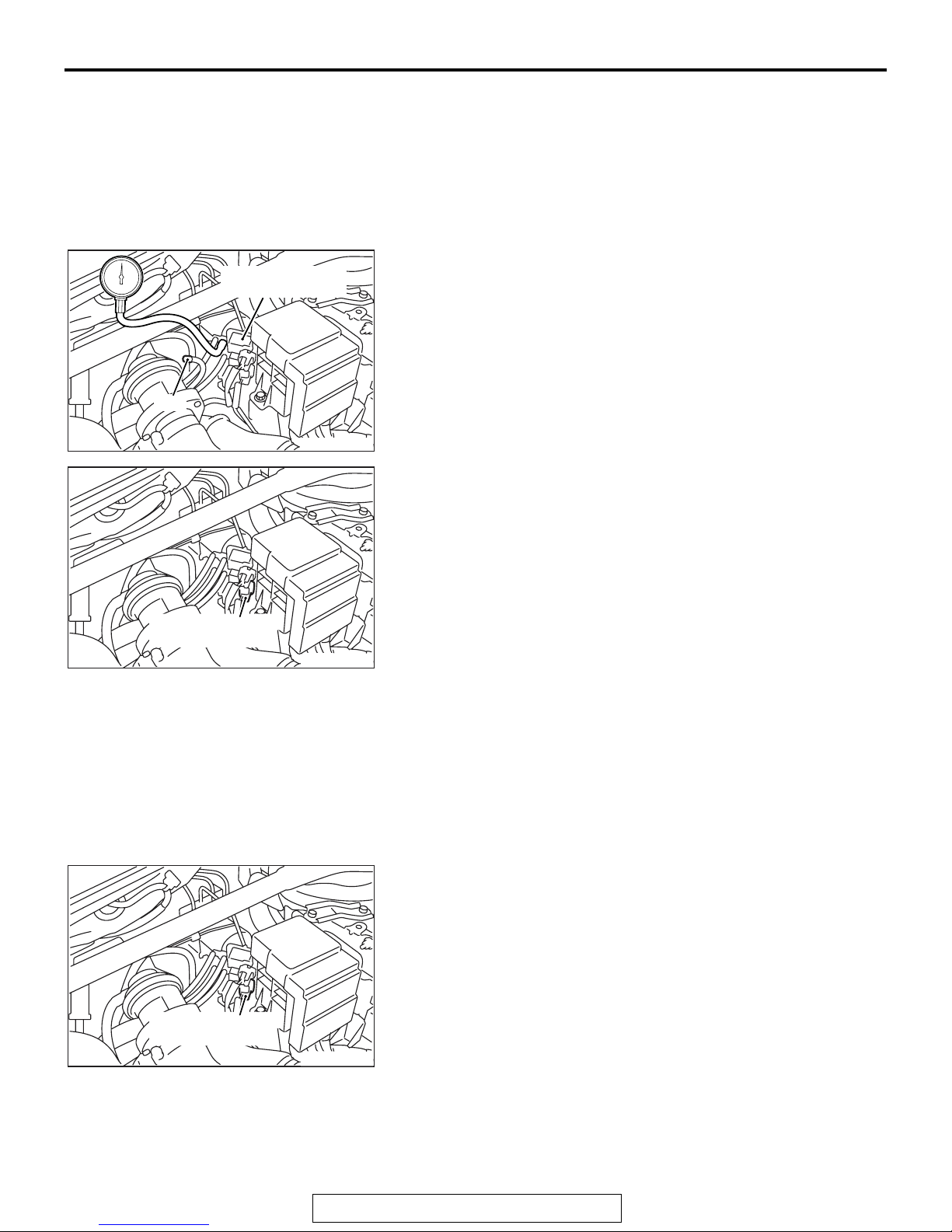
INTAKE CHARGE PRESSURE CHECK
M1151001000549
1. Removing the black hose from the No.1 turbocharger
wastegate solenoid or the brown connector, install the
pressure gauge to this hose. Cap the nipple of solenoid after
removing the black hose.
2. Disconnect the black connector of No.2 turbocharger
wastegate solenoid.
3. When the engine speed reaches approximately 3000r/min
or more with the throttle fully opened in the second gear,
measure the boost pressure.
Standard value: 85 − 159kPa (12.4 − 23.0 psi)
No. 2 turbochager
wastegate solenoid
No. 2 turbochager
wastegate solenoid
AK703283
AK703283
AC
AC
4. If the boost pressure is lower than the standard, check the
following possible causes.
a. Turbocharger wastegate actuator malfunction
b. Boost pressure leakage
c. Turbocharger malfunction
5. If the boost pressure is higher than the standard, check on
the following areas because the boost pressure control
might be abnormal.
a. Turbocharger wastegate actuator malfunction
b. Wastegate regulating valve malfunction
c. Rubber hose of turbocharger wastegate actuator discon-
nected or cracked
6. Connect the black connector of No.2 turbocharger
wastegate solenoid.
TSB Revision
15-6
Data link connector
MB991910
MB991824
INTAKE AND EXHAUST
ON-VEHICLE SERVICE
7. If the diagnostic trouble code is stored during the check, use
scan tool MB991958 to eliminate the diagnosis code.
MB991827
Turbochager wastegate actuator
AC608435
AK703279
AB
AC
TURBOCHARGER WASTEGATE ACTUATOR
CHECK
1. Connect a hand vacuum pump (pressure-application type)
to nipple.
CAUTION
In order to abovid damage to the diaphragm, do not apply
a pressure of 117 kPa (17 psi) or higher.
2. While gradually applying pressure, check the pressure that
begins to activate (approximately 1 mm stroke) the
wastegate actuator rod.
Standard value: 98 − 102 kPa (14.3 − 14.7 psi)
3. If there is a significant deviation from the standard value,
check the actuator or the wastegate valve: replace if
necessary.
M1151001200413
TSB Revision

Three-way joint
INTAKE AND EXHAUST
ON-VEHICLE SERVICE
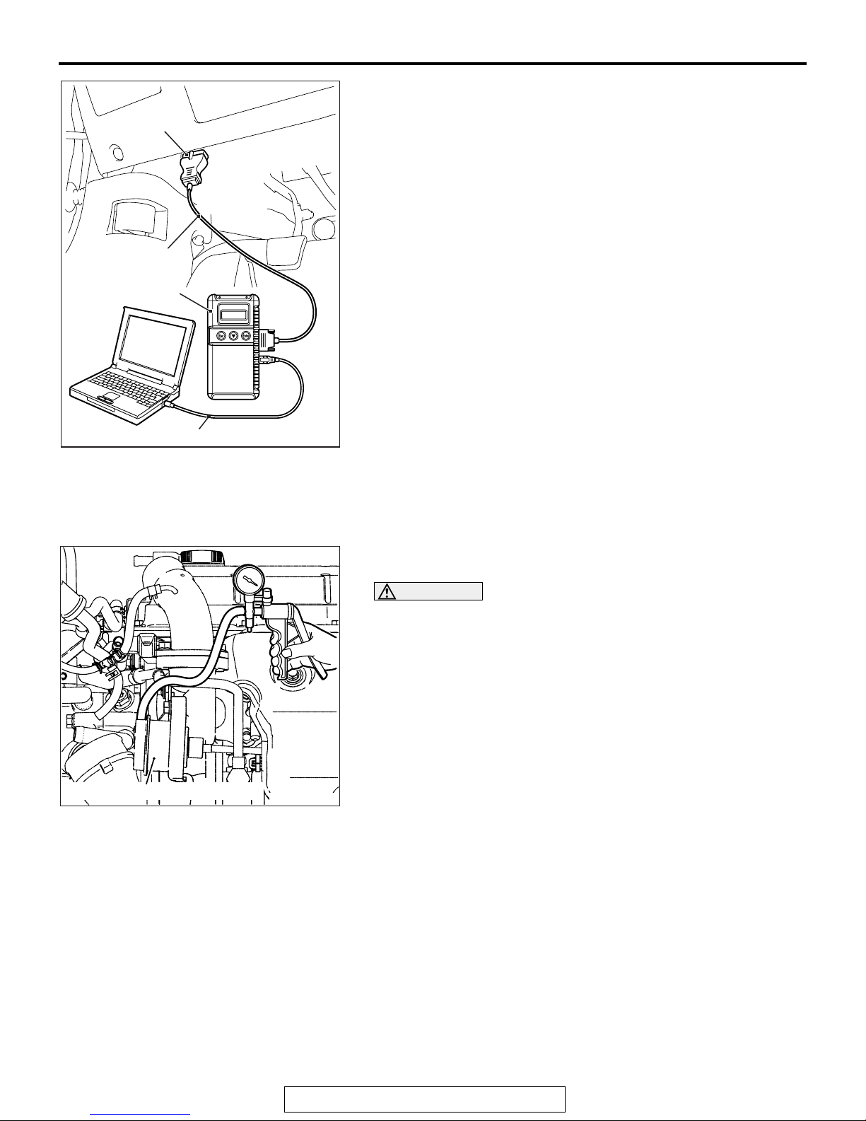
INTAKE CHARGE PRESSURE CONTROL SYSTEM
CHECK
1. Removing the black hose from the No.1 turbocharger
wastegate solenoid or the brown connector, connect
three-way joint between the hose and the solenoid.
2. Connect the pressurized type hand vacuum pump with the
three-way joint.
M1151001100342
15-7
Boost hose
Turbochager
wastegate actuator
AK703284
AK703105
No. 1 turbochager
wastegate solenoid valve
AC
AC
3. Use the turbocharger wastegate actuator control boost
nipple of air outlet fitting to remove the boost hose. Plug this
nipple.
CAUTION
Do not apply the pressure of 117kPA or more to prevent
the diaphragm damage.
4. Blocking or releasing the boost hose end, apply the
pressure. Check the pressurized state.
Engine state Boost hose end Normal state
Stopped: Ignition
switch in "ON"
position
Opened Pressure leaks
Closed Pressure
maintained
Rapid racing Pressure leaks
5. Put the ignition switch in "LOCK" (OFF) position.
6. Disconnect the connector of No.1 turbocharger wastegate
solenoid or the brown connector.
7. Blocking or releasing the boost hose end, apply the
pressure. Check the pressurized state. Plug the boost hose
end while driving.
AK703285
AC
NOTE: Unless the pressurized state is normal, the turbocharger wastegate actuator, turbocharger wastegate solenoid
or the hose might have a malfunction.
TSB Revision
Engine state Boost hose end Normal state
Stopped: Ignition
switch in "ON"
position
4000r/min after
Opened Pressure leaks
Closed Pressure
maintained
Pressure leaks
warming up
engine
15-8
A
B
No. 1 turbochager
wastegate solenoid valve
AK703285
AC
INTAKE AND EXHAUST
ON-VEHICLE SERVICE
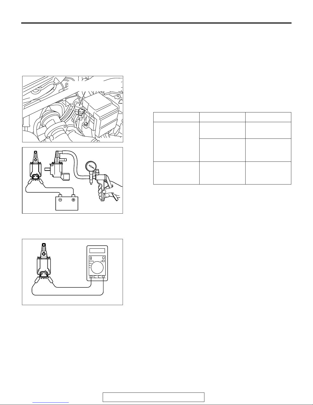
TURBOCHARGER WASTE GATE SOLENOID
CHECK
M1151001300272
No.1 turbocharger wastegate solenoid or brown
connector
.
A Operation check
1. Install the hand vacuum pump to the nipple "A" of solenoid.
2. Use the jumper wire to connect the solenoid terminal with
the battery terminal.
3. Disconnecting the jumper wire at the negative (-) battery
side, apply the vacuum pressure. Check the airtightness.
Jumper wire Nipple "B" state Normal state
Connected Opened Negative
pressure leaks
Closed Negative
pressure
maintained
Disconnected Opened Negative
pressure
maintained
BATTERY
AK200441
AK200442
AD
.
B Check of coil resistance
1. Measure the resistance between the solenoid terminals.
Standard value: 29 − 35 Ω at 20° C
TSB Revision
 Loading...