

Page 1

GROUP 26
FRONT AXLE
CONTENTS
26-1
GENERAL INFORMATION . . . . . . . . 26-2
SERVICE SPECIFICATIONS. . . . . . . 26-3
LUBRICANTS . . . . . . . . . . . . . . . . . . 26-3
SPECIAL TOOLS. . . . . . . . . . . . . . . . 26-3
ON-VEHICLE SERVICE. . . . . . . . . . . 26-6
WHEEL BEARING AXIAL PLAY CHECK . . 26-6
HUB BOLT REPLACEMENT . . . . . . . . . . . 26-6
FRONT AXLE HUB ASSEMBLY . . . . 26-7
REMOVAL AND INSTALLATION . . . . . . . . 26-7
INSPECTION. . . . . . . . . . . . . . . . . . . . . . . . 26-9
DISASSEMBLY AND REASSEMBLY . . . . . 26-10
INSPECTION. . . . . . . . . . . . . . . . . . . . . . . . 26-10
DRIVE SHAFT ASSEMBLY . . . . . . . . 26-12
REMOVAL AND INSTALLATION . . . . . . . . 26-12
DISASSEMBLY AND REASSEMBLY . . . . . 26-15
INSPECTION. . . . . . . . . . . . . . . . . . . . . . . . 26-18
EBJ BOOT (RESIN BOOT)
REPLACEMENT . . . . . . . . . . . . . . . . . . . . . 26-18
Page 2
26-2
FRONT AXLE
GENERAL INFORMATION
GENERAL INFORMATION
M1261000100444
The front axle consists of front wheel hub assembly,
knuckles and drive shafts, and has the following
features:
• The wheel bearing incorporates a unit ball
bearing (double-row angular contact ball bearing)
for reduced friction.
• The front wheel hub assembly combines the hub,
wheel bearing, housing, and oil seal in a single
unit for fewer parts, better rigidity, improved
assembly precision, and better structural
organization.
• The drive shaft on wheel side incorporates an
EBJ type constant velocity joint.
SPECIFICATIONS
Item Specification
Wheel bearing Type Unit ball bearing (Double-row
• The drive shaft on the differential side
incorporates a TJ type constant velocity joint.
• ABS rotor for detecting the wheel speed is
press-fitted to the EBJ.
• For environmental protection, a lead-free grease
is used on the joints.
NOTE: .
• EBJ: Eight Ball Fixed Joint; The use of the
smaller-sized eight balls inside the joint achieves
weight saving and compact size compared with a
BJ (Birfield Joint).
• TJ: Tripod Joint
angular contact ball bearing)
Driveshaft Joint type Outer EBJ
Inner TJ
Length (joint to joint) ×
diameter mm
Left 352.5 × 26
Right 429.5 × 26
NOTE: The wheel bearing is part of the hub,
therefore its size is not listed here.
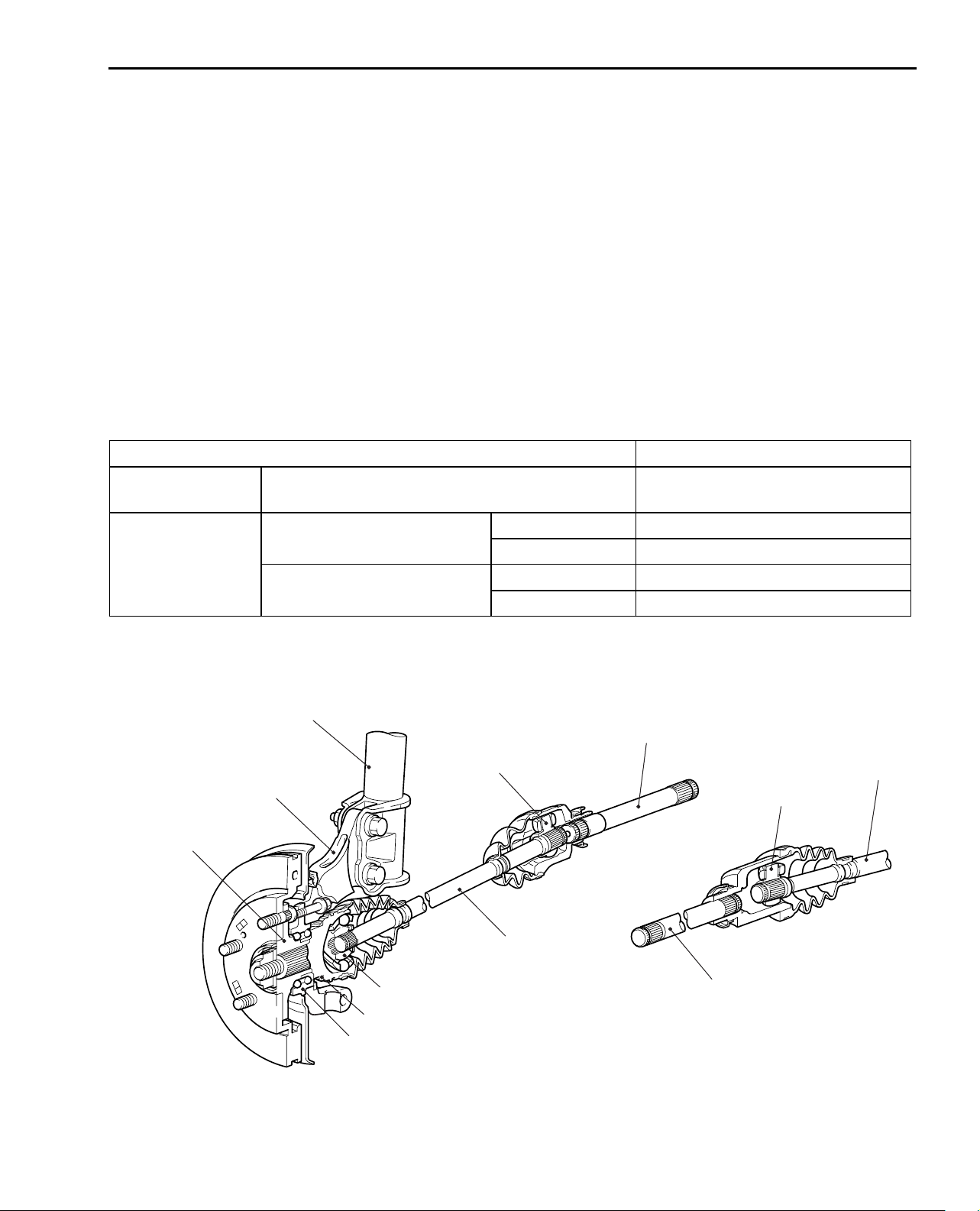
CONSTRUCTION DIAGRAM
Strut assembly
Output shaft
TJ (LH)
Knuckle
Front wheel
hub assembly
Drive shaft
(LH)
EBJ
Output shaft
TJ (RH)
Drive shaft
(RH)
ABS rotor
Wheel bearing
AC211166
AB
Page 3
FRONT AXLE
B990767
MB991618
AC106827
SERVICE SPECIFICATIONS
SERVICE SPECIFICATIONS
Item Standard value Limit
Wheel bearing axial play mm − 0.05
Wheel bearing rotation starting torque N⋅m − 1.03
Setting of TJ boot length mm 85 ± 3 −
26-3
M1261000300460
Opening dimension of the
special tool (MB991561) mm
Crimped width of the EBJ boot band mm 2.4 − 2.8 −
When the EBJ boot
band (small) is crimped
When the EBJ boot
band (large) is crimped
2.9 −
3.2 −
LUBRICANTS
Item Specified lubricant Quantity
TJ boot grease Repair kit grease 145 ± 10 g
EBJ boot grease Repair kit grease 100 ± 10 g
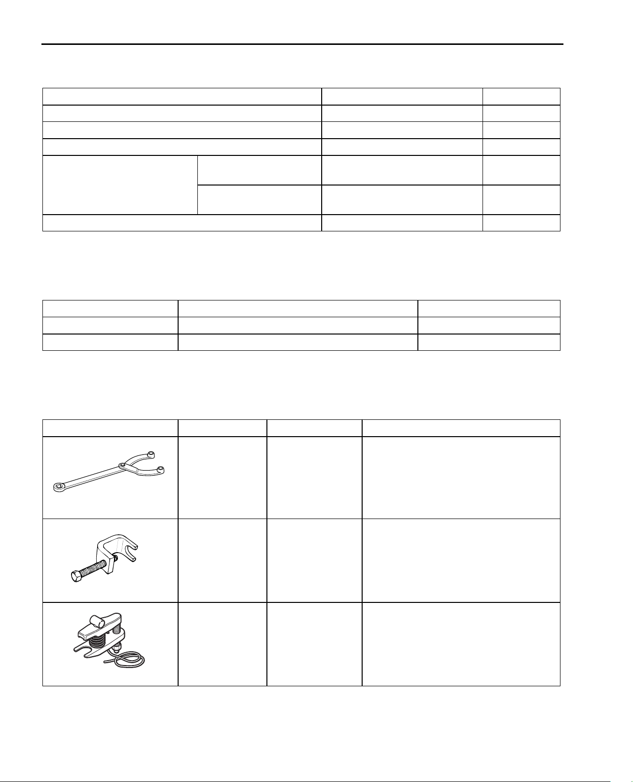
SPECIAL TOOLS
Tool Number Name Use
MB990767 End yoke holder Fixing of the hub
M1261000400490
M1261000600483
MB991618 Hub bolt remover Removal of the hub bolt
MB991897 Ball joint remover Knuckle and tie rod end ball joint
disconnection
NOTE: Steering linkage puller
(MB990635 or MB991113)is also used
to disconnect knuckle and tie rod end
ball joint.
Page 4
26-4
MB990241
AB
A
B
MB991354
MB990590
A
B
MB991721
AC100320AB
A
B
C
MB990326
FRONT AXLE
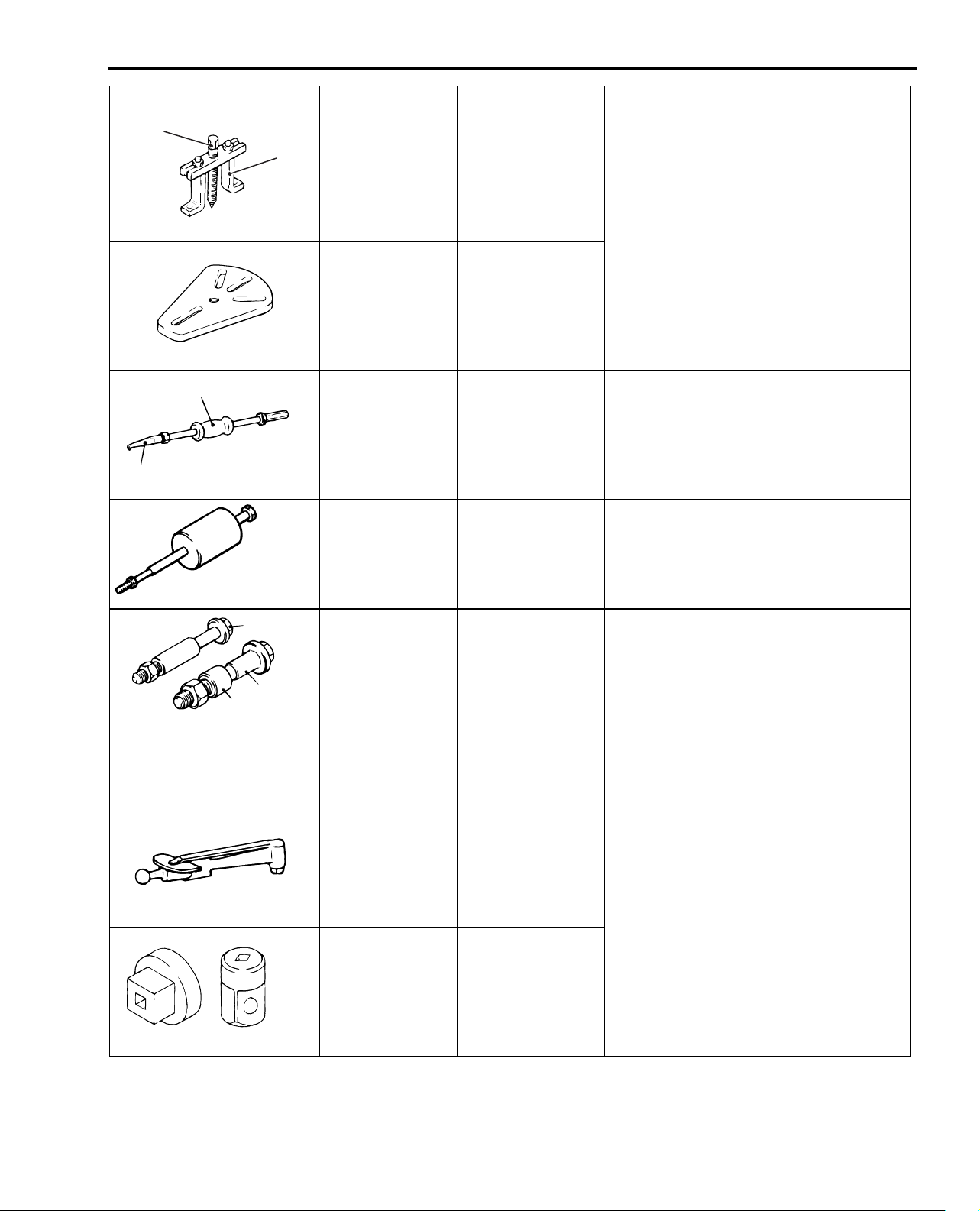
SPECIAL TOOLS
Tool Number Name Use
MB990241
A: MB990242
B: MB990244
Axle shaft puller
A: Puller shaft
B: Puller bar
Removal of the drive shaft
MB991354 Puller body
MB990590
A: MB990212
B: MB990211
Rear axle shaft oil
seal remover
A: Adapter
Removal of the front wheel hub
B: Slide hammer
MB991721 Slide hammer Removal of the output shaft
A: MB991017
B: MB990998
C: MB991000
A, B: Front hub
remover and
installer
C: Spacer
• Removal of the hub
• Provisional holding of the wheel
bearing
• Measurement of hub starting torque
• Measurement of wheel bearing axial
play
NOTE: MB991000, which belongs to
MB990998, should be used as a
spacer.
MB990685 Torque wrench Measurement of hub starting torque
MB990326 Preload socket
Page 5
FRONT AXLE
MB991561
MB990925
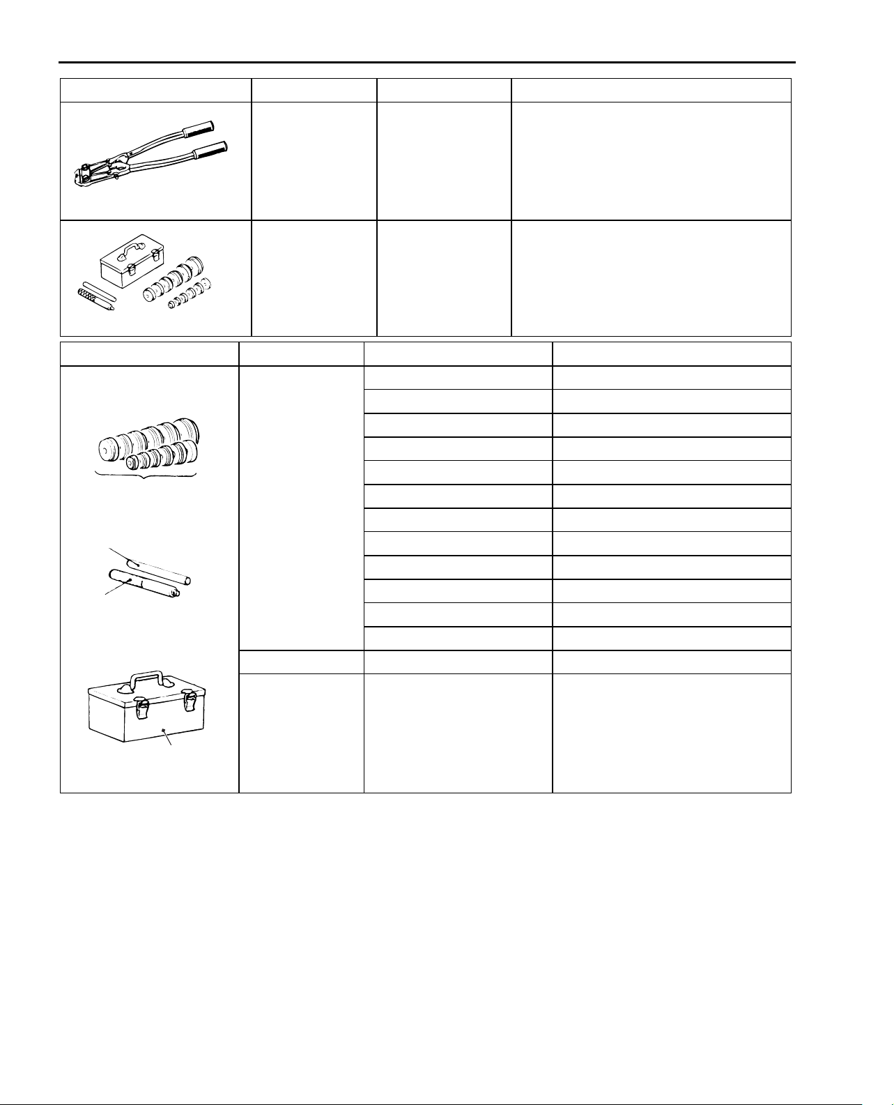
SPECIAL TOOLS
Tool Number Name Use
26-5
MB991561 Boot band
BJ boot (resin boot) band installation
crimping tool
MB990925 Bearing and oil
seal installer set
• Removal of the wheel bearing
• Removal and installation of the
centre bearing
• Press-fitting of the dust seal outer,
inner
Tool Type Tool number O D mm
MB990925
A MB990926 39.0
MB990927 45.0
MB990928 49.5
MB990929 51.0
MB990930 54.0
A
Installer adapter
MB990931 57.0
MB990932 61.0
C
Brass bar
MB990933 63.5
MB990934 67.5
B
Bar (snap-in type)
Tool box
ACX02372
MB990935 71.5
MB990936 75.5
MB990937 79.0
B MB990938 −
C MB990939 −
AC
Page 6
26-6
!
CAUTION
!
CAUTION
FRONT AXLE
ON-VEHICLE SERVICE
ON-VEHICLE SERVICE
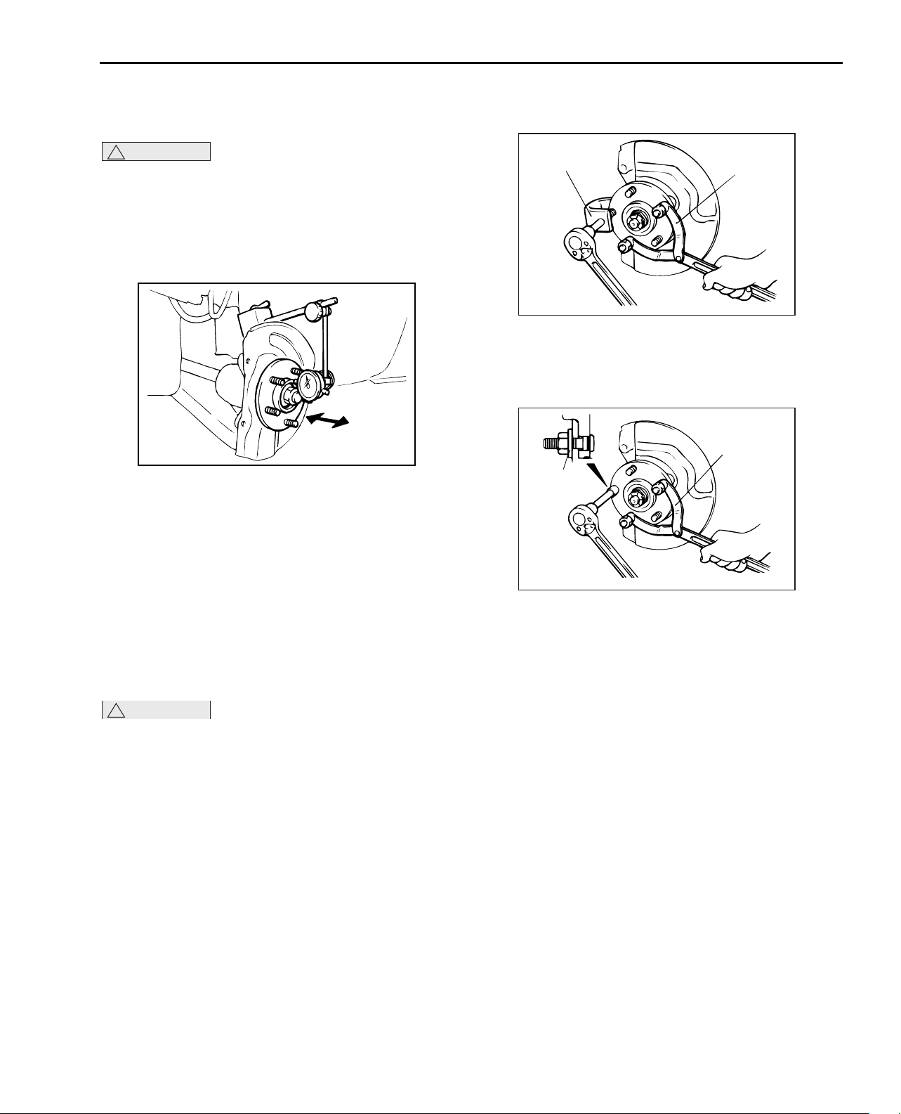
WHEEL BEARING AXIAL PLAY CHECK
M1261000900268
During maintenance, take care not to contact the
parts or tools to the caliper because the paint of
caliper will be scratched.
1. Remove the caliper assembly and suspend it with
a wire.
2. Remove the brake disc from the front hub.
AC102438AD
3. Attach a dial gauge as shown in the illustration,
and then measure the axial play while moving the
hub in the axial direction.
Limit: 0.05 mm
4. If axial play exceeds the limit, disassemble the
front hub assembly and check the parts.
5. Install the brake disc, caliper assembly and
tighten the caliper assembly mounting bolts to the
specified torque 108 ± 10 N⋅m.
HUB BOLT REPLACEMENT
M1261001000332
2. Remove the brake disc.
MB991618
MB990767
AC102439AC
3. Use the following special tools to remove the hub
bolts.
• End yoke holder (MB990767)
• Hub bolt remover (MB991618)
MB990767
Plain
washer
AC102440
AC
4. Install the plain washer to the new hub bolt, and
install the bolt with a nut.
5. Install the brake disc, caliper assembly and
tighten the caliper assembly mounting bolts to the
specified torque 108 ± 10 N⋅m.
During maintenance, take care not to contact the
parts or tools to the caliper because the paint of
caliper will be scratched.
1. Remove the caliper assembly and suspend it with
wire so that it does not fall.
Page 7

FRONT AXLE
!
CAUTION
FRONT AXLE HUB ASSEMBLY
26-7
FRONT AXLE HUB ASSEMBLY
REMOVAL AND INSTALLATION
M1261001700483
• Do not strike the ABS rotors installed to the EBJ outer race of drive shaft against other parts when
removing or installing the drive shaft. Otherwise the ABS rotors will be damaged.
• Be careful not to strike the pole piece at the tip of the front ABS sensor with tools during servicing
work.
• During maintenance, take care not to contact the parts or tools to the caliper because the paint of
caliper will be scratched. And if there is brake fluid on the caliper, wipe off quickly.
Pre-installation Operation
• Front Under Cover, Side Under Cover Removal
• Transmission Oil Draining (Refer to
GROUP22A, On-vehicle Service − Manual
Transmission Oil P.22A-149. )
• Transfer Oil Draining (Refer to GROUP22A,
On-vehicle Service −Transfer Oil P.22A-149. )
11
167 ± 9 N·m
12
10
108 ± 10 N·m
Post-installation Operation
• Check the dust cover for cracks or damage by
pushing it with your finger.
• Transfer Oil Filling (Refer to GROUP 22A,
On-vehicle Service−Transfer Oil P.22A-149. )
• Transmission Oil Filling (Refer to GROUP22A,
On-vehicle Service − Manual Transmission Oil
P.22A-149).
• Front Under Cover, Side Under Cover
Installation
25 ± 5 N·m
N
9
4
7
8.9 ± 1.9 N·m
6
<<A>> >>A<<
>>A<<
<<B>>
<<C>>
8
5
Removal steps
1. Split pin
2. Drive shaft nut
3. Washer
4. Front ABS sensor
5. Caliper assembly
6. Brake disc
7. Dust cover
108 ± 10 N·m
<<D>>
<<E>>
3
1
226 ± 19 N·m
Removal steps (Continued)
8. Connection for lower arm ball joint
9. Self-locking nut (tie rod end
connection)
10. Drive shaft
11. Nut (hub and knuckle to strut
connection)
12. Hub and knuckle assembly
2
AC211630
N
AC
Page 8

26-8
!
CAUTION
!
CAUTION
FRONT AXLE
FRONT AXLE HUB ASSEMBLY
REMOVAL SERVICE POINTS
<<A>> DRIVE SHAFT NUT REMOVAL
Do not apply pressure to wheel bearing by the
vehicle weight to avoid possible damage when
drive shaft nut is loosened.
MB990767
AC102462
AC
Use special tool end yoke holder (MB990767) to fix
the hub and remove the drive shaft nut.
<<B>> CALIPER ASSEMBLY REMOVAL
<<D>> SELF-LOCKING NUT (TIE ROD
END CONNECTION) REMOVAL
CAUTION
!
• Do not remove the nut from ball joint. Loosen
it and use the special tool to avoid possible
damage to ball joint threads.
• Hang the special tool with cord to prevent it
from falling.
Cord
Nut
Ball joint
1. Install special tool ball joint remover (MB991897)
as shown in the figure.
MB991897
Bolt
AC208247
AD
During maintenance, take care not to contact the
parts or tools to the caliper because the paint of
caliper will be scratched.
Secure the removed caliper assembly with wire, etc.
<<C>> BRAKE DISC REMOVAL
Bolts
(M8×1.25)
AC205799
If the brake disc is seized, install a M8×1.25 mm
bolts as shown, and remove the disc by tightening
the bolts evenly and gradually.
AC
Bolt
Parallel
Knob
Correct
Wrong
AC106821
AD
2. Turn the bolt and knob as necessary to make the
jaws of special tool parallel, tighten the bolt by
hand and confirm that the jaws are still parallel.
NOTE: When adjusting the jaws in parallel, make
sure the knob is in the position shown in the
figure.
3. Tighten the bolt with a wrench to disconnect the
tie rod end.
Page 9

FRONT AXLE
AC201827
MB991354
MB990244
(Three)
MB990242
MB990767
AE
AC102551
AC
Drive shaft
FRONT AXLE HUB ASSEMBLY
26-9
<<E>> DRIVE SHAFT REMOVAL
1. Use the following special tools to push out the
drive shaft from the hub and knuckle.
• Puller shaft (MB990242)
• Puller bar (MB990244)
• Puller body (MB991354)
• End yoke holder (MB990767)
INSTALLATION SERVICE POINT
>>A<< WASHER/ DRIVE SHAFT NUT
INSTALLATION
CAUTION
!
Before securely tightening the drive shaft nuts,
make sure there is no load on the wheel
bearings. Otherwise the wheel bearings will be
damaged.
Washer
MB990767
AC102465
1. Be sure to install the drive shaft washer in the
specified direction.
2. Using special tool end yoke holder (MB990767),
tighten the drive shaft nut to the specified torque.
Tightening torque: 226 ± 19 N⋅m
AD
2. Withdraw the drive shaft from the hub by pulling
the bottom of the hub and knuckle towards you.
3. Hang the drive shaft on the vehicle body with a
rope.
INSPECTION
M1261001800286
• Check the hub for cracks and spline for wear.
• Check the knuckle for cracks.
Page 10

26-10
FRONT AXLE
FRONT AXLE HUB ASSEMBLY
DISASSEMBLY AND REASSEMBLY
88 ± 10 N·m
Disassembly steps
1. Knuckle
<<A>>
2. Front wheel hub assembly
DISASSEMBLY SERVICE POINTS
1
2
INSPECTION
WHEEL BEARING ROTATION STARTING TORQUE AND AXIAL PLAY CHECK
M1261001900261
AC211631
M1261002000108
AC
<<A>> FRONT WHEEL HUB ASSEMBLY
REMOVAL
1. If the front wheel hub is seized, remove the
knuckle together with front wheel hub and fix them
with a vise.
MB990244
MB990211
MB991354
2. Use the following special tools to pull out the front
wheel hub from the knuckle.
• Puller bar (MB990244)
• Puller body (MB991354)
• Slide hammer (MB990211)
AC210309
AE
MB991017
MB991000
AC301927
AF
1. Tighten the following special tools to the specified
torque.
• Front hub remover and installer (MB991017)
• Spacer (MB991000)
Tightening torque: 226 ± 19 N⋅m
2. Hold the front wheel hub assembly in a vice with a
wooden block.
3. Rotate the hub in order to seat the bearing.
Page 11

FRONT AXLE
AC206090
AD
MB990326
Wooden
block
MB990685
Wooden
block
FRONT AXLE HUB ASSEMBLY
Wooden
block
MB991017
Wooden
block
AC206091
26-11
AG
4. Measure the wheel bearing rotation starting
torque by using the following special tools.
• Preload socket (MB990326)
• Torque wrench (MB990685)
Limit: 1.03 N⋅m
5. If the rotation starting torque is not within the limit
range while the nut is tightened to 226 ± 19 N⋅m,
replace the front wheel hub assembly. If there are
any signs of binding or tight spots when the wheel
bearing turns, replace it.
6. Measure to determine whether the wheel bearing
axial play is within the specified limit or not.
Limit: 0.05 mm
7. If the play is not within the limit range while the nut
is tightened to 226 ± 19 N⋅m, replace the front
wheel hub assembly.
Page 12

26-12
!
CAUTION
FRONT AXLE
DRIVE SHAFT ASSEMBLY
DRIVE SHAFT ASSEMBLY
REMOVAL AND INSTALLATION
M1261003500537
• Do not strike the ABS rotors installed to the EBJ outer race of drive shaft against other parts when
removing or installing the drive shaft. Otherwise the ABS rotors will be damaged.
• Be careful not to strike the pole piece at the tip of the front ABS sensor with tools during servicing
work.
• During maintenance, take care not to contact the parts or tools to the caliper because the paint of
caliper will be scratched. And if there is brake fluid on the caliper, wipe off quickly.
Pre-installation Operation
• Front under cover, side under cover removal
• Transmission Fluid Draining (Refer to GROUP
22A, On-vehicle service − Transmission oil
replacement P.22A-149).
• Transfer Oil Draining (Refer to GROUP 22A,
On-vehicle service − Transfer oil P.22A-149).
N
12
10
11
12
N
39 ± 5 N·m
Post-installation Operation
• Check the ball Joint dust cover for cracks or
damage by pushing it with your finger.
• Transfer Oil Filling (Refer to GROUP 22A,
On-vehicle service − Transfer oil P.22A-149).
• Transmission Fluid Filling (Refer to GROUP
22A, On-vehicle service − Transmission oil
replacement P.22A-149).
• Front Under cover, side under cover Installation
6
5
N
25 ± 5 N·m
9
4
3
1
2
7
N
<<A>> >>B<<
>>B<<
39 ± 5 N·m
8
Removal steps
1. Split pin
2. Drive shaft nut
3. Washer
4. Front ABS sensor
5. Front ABS sensor harness bracket
6. Brake hose bracket
7. Stabilizer bar link connection
108 ± 10 N·m
<<B>>
<<C>> >>A<<
<<D>> >>A<<
226 ± 29 N·m
AC211632
Removal steps (Continued)
8. Lower arm ball joint connection
9. Self-locking nut (tie rod end
connection)
10. Drive shaft
11. Output shaft
12. Circlip
AC
Page 13

DRIVE SHAFT ASSEMBLY
!
CAUTION
!
CAUTION
AC102462
AC
MB990767
AC208247
AD
Cord
Bolt
MB991897
Nut
Ball joint
REMOVAL SERVICE POINTS
FRONT AXLE
26-13
<<A>> DRIVE SHAFT NUT REMOVAL
Do not apply pressure to the wheel bearing by
the vehicle weight to avoid possible damage
when the drive shaft nut is loosened.
Use special tool end yoke holder (MB990767) to fix
the hub and remove the drive shaft nut.
<<B>> SELF-LOCKING NUT (TIE ROD
END CONNECTION) REMOVAL
Bolt
Parallel
Knob
Correct
Wrong
AC106821
AD
2. Turn the bolt and knob as necessary to make the
jaws of special tool parallel, tighten the bolt by
hand and confirm that the jaws are still parallel.
NOTE: When adjusting the jaws in parallel, make
sure the knob is in the position shown in the
figure.
3. Tighten the bolt with a wrench to disconnect the
tie rod end.
<<C>> DRIVE SHAFT REMOVAL
• Do not remove the nut from ball joint. Loosen
it and use special tool to avoid possible
damage to ball joint threads.
• Hang special tool with cord to prevent it from
falling.
1. Install special tool ball joint remover (MB991897)
as shown in the figure.
MB990767
MB990244
(Three)
MB990242
MB991354
AC102550
AC
1. Use the following special tools to push out the
drive shaft from the hub.
• Puller shaft (MB990242)
• Puller bar (MB990244)
• Puller body (MB991354)
• End yoke holder (MB990767)
Drive shaft
AC102551
AC
2. Remove the drive shaft from the hub by pulling
the bottom of the brake disc towards you.
Page 14

26-14
!
CAUTION
!
CAUTION
• Do not pull on the drive shaft; doing so will
damage the TJ; be sure to use the pry bar.
• When pulling the drive shaft out from the
transmission, be careful that the spline part of
the drive shaft does not damage the oil seal.
FRONT AXLE
DRIVE SHAFT ASSEMBLY
<<D>>OUTPUT SHAFT REMOVAL
CAUTION
!
When pulling the output shaft out from the
tansaxle, be careful that the spline part of the
output shaft does not damage the oil seal.
Transmission
TJ assembly
Pry bar
AC100141
AG
3. Insert a pry bar between the transmission case
and the drive shaft, and then pry and remove the
drive shaft from the transmission.
MB991000
MB991017
AC210315
AF
Do not apply pressure to the wheel bearing by
the vehicle weight to avoid possible damage
when the drive shaft is removed. If, however,
vehicle weight must be applied to the bearing in
moving the vehicle, temporarily secure the wheel
bearing by using the following special tools.
• Spacer (MB991000)
• Front hub remover and installer (MB991017)
MB991721
Output shaft
AC102556
AC
Use special tool slide hammer (MB991721) to
remove the output shaft.
INSTALLATION SERVICE POINTS
>>A<< OUTPUT SHAFT/DRIVE SHAFT
INSTALLATION
CAUTION
!
When installing the output shaft or the drive
shaft, be careful that the spline part of the output
shaft or the drive shaft do not damage the oil
seal.
>>B<< WASHER/DRIVE SHAFT NUT
INSTALLATION
Washer
MB990767
AC102465
AD
1. Be sure to install the drive shaft washer in the
specified direction.
CAUTION
!
Before securely tightening the drive shaft nuts,
make sure there is no load on the wheel
bearings. Otherwise the wheel bearing will be
damaged.
2. Using special tool end yoke holder (MB990767),
tighten the drive shaft nut to the specified torque.
Tightening torque: 226 ± 29 N⋅m
Page 15

FRONT AXLE
!
CAUTION
DRIVE SHAFT ASSEMBLY
26-15
DISASSEMBLY AND REASSEMBLY
M1261003700586
• Be careful not to damage the ABS rotor, which is attached to the EBJ outer race during
disassembly and reassembly.
• Never disassemble the EBJ assembly except when replacing the EBJ boot.
3
4
N
5
6
N
2
N
1
3
4
5
6
1
2
TJ boot repair kit TJ repair kit
Disassembly steps
>>D<<
>>D<<
<<A>> >>C<<
<<A>> >>B<<
<<B>> >>A<<
1. TJ boot band (large)
2. TJ boot band (small)
3. TJ case
4. Snap ring
5. Spider assembly
6. TJ boot
7. EBJ assembly
9
7
8
10
6
4
1
Grease
for EBJ
Grease
for TJ
2
EBJ boot repair kit
8. EBJ boot band (small)
9. EBJ boot band (large)
10. EBJ boot
NOTE: .
• TJ: Tripod Joint
• EBJ: Eight Ball Fixed Joint
4
1
2
8
9
10
AC211633
Disassembly steps (Continued)
AC
Page 16

26-16
!
CAUTION
LUBRICATION POINTS
FRONT AXLE
DRIVE SHAFT ASSEMBLY
5
Grease: repair kit grease
Amount used: 145 ± 10 g
CAUTION
The drive shaft joint uses special
grease. Do not mix old and new or
different types of grease.
Grease: repair kit grease
Amount used: 100 ± 10 g
CAUTION
The drive shaft joint uses special
grease. Do not mix old and new or
different types of grease.
DISASSEMBLY SERVICE POINTS
<<A>> TJ CASE/SPIDER ASSEMBLY
REMOVAL
Do not disassemble the spider assembly.
AC211634
AC
1. Wipe off grease from the spider assembly and the
inside of the TJ case.
2. Always clean the spider assembly when the
grease contains water or foreign material.
Page 17

FRONT AXLE
!
CAUTION
AC102654AC
Chamfered
side
DRIVE SHAFT ASSEMBLY
26-17
<<B>> TJ BOOT REMOVAL
1. Wipe off grease from the shaft spline.
2. When reusing the TJ boot, wrap plastic tape
around the shaft spline to avoid damaging the
boot.
REASSEMBLY SERVICE POINTS
>>A<< TJ BOOT INSTALLATION
Wrap plastic tape around the shaft spline, and then
install the TJ boot band (small) and TJ boot.
>>B<< SPIDER ASSEMBLY
INSTALLATION
• The drive shaft joint use special grease. Do
not mix old and new or different types of
grease.
• If the spider assembly has been cleaned, take
special care to apply the specified grease.
1. Apply the specified grease furnished in the repair
kit to the spider assembly between the spider axle
and the roller.
Specified grease: Repair kit grease
>>C<< TJ CASE INSTALLATION
CAUTION
!
The drive shaft joint uses special grease. Do not
mix old and new or different types of grease.
AC102656
AC
After applying the specified grease to the TJ case,
insert the drive shaft and apply grease one more
time.
Specified grease: Repair kit grease
Amount to use: 145 ± 10 g
NOTE: The grease in the repair kit should be divided
in half for use, respectively, at the joint and inside the
boot.
>>D<< TJ BOOT BAND (SMALL)/TJ BOOT
BAND (LARGE) INSTALLATION
2. Install the spider assembly to the shaft from the
direction of the spline chamfered side.
A
AC102657
AC
Set the TJ boot bands at the specified distance in
order to adjust the amount of air inside the TJ boot,
and then tighten the TJ boot band (small), TJ boot
band (large) securely.
Standard value (A): 85 ± 3 mm
Page 18

26-18
FRONT AXLE
DRIVE SHAFT ASSEMBLY
INSPECTION
M1261003800215
• Check the drive shaft for damage, bending or
corrosion.
• Check the drive shaft spline part for wear or
damage.
• Check the spider assembly for roller rotation,
wear or corrosion.
• Check the groove inside TJ case for wear or
corrosion.
• Check the boots for deterioration, damage or
cracking.
EBJ BOOT (RESIN BOOT) REPLACEMENT
M1261005200435
AC102658
1. Remove the boot bands (large and small).
NOTE: The boot bands cannot be re-used.
2. Remove the EBJ boot.
3. Wrap a plastic tape around the shaft spline, and
assemble the boot band and EBJ boot.
MB991561
Stopper
W
Adjusting bolt
AC102660
AC
5. Turn the adjusting bolt on special tool boot band
crimping tool (MB991561) so that the size of the
opening (W) is at the standard value.
Standard value (W): 2.9 mm
<If it is larger than 2.9 mm> Tighten the
adjusting bolt.
<If it is smaller than 2.9 mm> Loosen the
adjusting bolt.
NOTE: The value of W will change by
approximately 0.7 mm for each turn of the
adjusting bolt.
NOTE: The adjusting bolt should not be turned
more than once.
Boot
A
Boot band
(small)
B
AC102659
4. Align the centre groove on the EBJ boot small end
with the shaft groove.
Projection
AC102661AC
6. Position the EBJ boot band (small) so that there is
even clearance at either end (A and B).
Page 19

FRONT AXLE
!
CAUTION
AC102663AC
MB991561
AC102662
C
AD
DRIVE SHAFT ASSEMBLY
• Secure the drive shaft in an upright position
and clamp part of the boot band to be
crimped securely in the jaws of special tool.
• Crimp the boot band until special tool
touches the stopper.
7. Use the special tool to crimp the boot band
(small).
26-19
9. Check that the boot band is not sticking out past
the place where it has been installed. If the boot
band is sticking out, remove it and then repeat
steps 6 to 8, using a new boot band.
CAUTION
!
The drive shaft joint uses special grease. Do not
mix old and new or different types of grease.
10.Fill the inside of the boot with the specified
amount of the specified grease.
Specified grease: Repair kit grease
Amount to use: 100 ± 10 g
8. Check that the crimping amount (C) of the boot
band is at the standard value.
Standard value (C): 2.4 − 2.8 mm
<If the crimping amount is larger than 2.8 mm >
Readjust the value of (W) in step 5 according
to the following formula, and then repeat the
operation in step 7.
W = 5.5 mm − C
Example: If C = 2.9 mm, then W = 2.6 mm.
<If the crimping amount is smaller than 2.4
mm >
Remove the EBJ boot band, readjust the
value of (W) in step 5 according to the
following formula, and then repeat the
operations in steps 6 and 7 using a new EBJ
boot band.
W = 5.5 mm − C
Example: If C = 2.3 mm, then W = 3.2 mm.
AC102664
AC
11.Align the centre groove on the EBJ boot big end
with the EBJ case groove.
12.Follow the same procedure as in step 5 to adjust
the size of the opening (W) on the special tool so
that it is at the standard value.
Standard value (W): 3.2 mm
Projection
D
Boot band
(large)
Boot
E
AC102665
AC
13.Position the EBJ boot band (large) so that there is
even clearance at either end (D and E).
14.Use the special tool to crimp the EBJ boot band
(large) in the same way as in step 7.
Page 20

26-20
FRONT AXLE
DRIVE SHAFT ASSEMBLY
16.Check that the boot band is not sticking out past
the place where it has been installed. If the boot
band is sticking out, remove it and then repeat
steps 13 to 15, using a new boot band.
F
AC102666
AD
15.Check that the crimping amount (F) of the boot
band is at the standard value.
Standard value (F): 2.4 − 2.8 mm
<If the crimping amount is larger than 2.8 mm >
Readjust the value of (W) in step 12
according to the following formula, and then
repeat the operation in step 14.
W = 5.8 mm − F
Example: If F = 2.9 mm, then W = 2.9 mm.
<If the crimping amount is smaller than 2.4
mm >
Remove the EBJ boot band, readjust the
value of (W) in step 12 according to the
following formula, and then repeat the
operations in steps 13 and 14 using a new
EBJ boot band.
W = 5.8 mm − F
Example: If F = 2.3 mm, then W = 3.5 mm.
 Loading...