

Page 1

РУКОВОДСТВО ПО УСТАНОВКЕ
Для безопасного и правильного использования внимательно прочитайте данное руководство и руководство по установке
наружного блока перед установкой гидромодуля. Оригинальная версия на английском языке, другие - перевод с оригинала.
TIL INSTALLATØREN
FÖR INSTALLATÖREN
PARA O INSTALADOR
PER L’INSTALLATORE
PARA EL INSTALADOR
VOOR DE INSTALLATEUR
POUR L’INSTALLATEUR
FÜR INSTALLATEURE
FOR INSTALLER
INSTALLATION MANUAL
For safe and correct use, read this manual and the outdoor unit installation manual thoroughly before installing
the hydrobox. English is the original language. The other language versions are translations of the original.
INSTALLATIONSHANDBUCH
Aus Sicherheitsgründen und zur richtigen Verwendung vor der Installation der Hydrobox die vorliegende Bedienungsanleitung und die Installationsanleitung
der Außeneinheit gründlich durchlesen. Die Originalsprache ist Englisch. Die anderen Sprachversionen sind vom Original übersetzt.
MANUEL D’INSTALLATION
Pour une utilisation correcte et sûre, lisez soigneusement ce manuel et le manuel d’installation de l’unité extérieure avant d’installer
l’ECODAN hydrobox. L’anglais est la langue originale. Les versions fournies dans d’autres langues sont des traductions de l’original.
INSTALLATIEHANDLEIDING
Lees voor een veilig en juist gebruik deze handleiding en de installatiehandleiding van de buiten-unit aandachtig door voordat u met
de installatie van de hydrobox begint. Engels is de oorspronkelijke taal. De andere taalversies zijn vertalingen van het origineel.
MANUAL DE INSTALACIÓN
Para un uso correcto y seguro, lea detalladamente este manual y el manual de instalación de la unidad exterior antes de instalar
la Hydrobox. El idioma original del documento es el inglés. Las versiones en los demás idiomas son traducciones del original.
MANUALE DI INSTALLAZIONE
Per un utilizzo sicuro e corretto, prima di installare l’Hydrobox leggere attentamente questo manuale e quello di installazione
dell’unità esterna. Il testo originale è redatto in lingua inglese. Le altre versioni linguistiche rappresentano traduzioni dell’originale.
MANUAL DE INSTALAÇÃO
Para uma utilização segura e correcta, leia este manual e o manual de instalação da unidade interior antes de instalar
o permutador de calor. O idioma original é o inglês. As versões em outros idiomas são traduções do idioma original.
INSTALLATIONSMANUAL
Af hensyn til sikker og korrekt brug skal denne vejledning og vejledningen til udendørsenheden læses omhyggeligt, inden
hydroboxenheden installeres. Engelsk er det oprindelige sprog. De andre sprogversioner er oversættelser af originalen.
INSTALLATIONSMANUAL
För säker och korrekt användning, läs denna manual och utomhusenhetens installationsmanual innan du
installerar hydroboxen. Engelska är originalspråket. De övriga språkversionerna är översättningar av originalet.
INSTALLERINGSHÅNDBOK
For å sikre en trygg og riktig bruk skal du lese denne håndboken og installeringshåndboken for utendørsenheten grundig
før du monterer hydroboksen. Engelsk er originalspråket. De andre språkversjonene er oversettelser av originalen.
ASENNUSOPAS
Lue turvallista ja asianmukaista käyttöä varten tämä opas ja ulkoyksikön asennusopas huolellisesti ennen
hydroboxin asentamista. Alkuperäiskieli on englanti. Muut kieliversiot ovat alkuperäisen käännöksiä.
ASENTAJALLE
FOR MONTØREN
Hydrobox
Гидромодуль без накопительного бака ГВС
EHSC series EHSD series EHPX series
ERSC series ERSD series
Русский (RU)
ДЛЯ МОНТАЖНИКОВ
Česky (CZ)
PRO TECHNIKY PROVÁDĚJÍCÍ INSTALACI
PŘÍRUČKA PRO INSTALACI
Z bezpečnostních důvodů a pro správné použití zásobníkového modulu si před jeho instalací důkladně prostudujte Návod k obsluze
a také Příručku pro instalaci venkovní jednotky. Jazyk originálu je angličtina. Jiné jazykové verze jsou překlady z originálu.
Polski (PL)
DLA INSTALATORA
INSTRUKCJA MONTAŻU
Należy dokładnie zapoznać się z niniejszą instrukcją obsługi i instrukcją montażu jednostki zewnętrznej, aby następnie bezpiecznie i z dobrym skutkiem użytkować
moduł wewnętrzny z wbudowanym zasobnikiem CWU.Oryginał dokumentu jest dostępny w języku angielskim. Inne wersje językowe są tłumaczeniami oryginału.
ЗА ИНСТАЛАТОРИ
РЪКОВОДСТВО ЗА МОНТАЖ
С оглед на безопасността и за правилна употреба на Hydrobox прочетете внимателно – преди монтажа – настоящото ръководството за
потребителя и ръководството за монтаж на външното тяло. Оригиналният език е английски. Другите езикови варианти са превод от оригинал.
Български (BG)
Español (ES)
Italiano (IT)
Português (PT)
Dansk (DA)
Svenska (SV)
Norsk (NO)
Suomi (FI)
English (EN)
Deutsch (DE)
Français (FR)
Nederlands (NL)
Page 2
1
EN
Contents
1. Safety Notices .................................................................. 2
2. Introduction ...................................................................... 2
3. Technical Information ...................................................... 3
4. Installation ....................................................................... 9
4.1 Location ........................................................................ 9
4.2 Water Quality and System Preparation .................... 12
4.3 Water Pipe Work ......................................................... 12
4.4 Electrical Connection ................................................ 15
5. System Set UP ................................................................ 18
5.1 DIP Switch Functions ................................................ 18
5.2 Connecting inputs/outputs ....................................... 19
5.3 Wiring for 2-zone temperature control .................... 20
5.4 2-zone valve ON/OFF control .................................... 21
5.5 Indoor unit only operation ......................................... 21
5.6 Smart grid ready......................................................... 21
5.7 Installation procedure for DHW tank ........................ 22
5.8 Remote Controller Options ....................................... 24
5.9 Using SD memory card.............................................. 26
5.10 Main remote controller ............................................ 27
6. Service and Maintenance .............................................. 35
7. Supplementary information .......................................... 40
Abbreviations and glossary
No. Abbreviations/Word Description
1 Compensation curve mode Space heating incorporating outdoor ambient temperature compensation
2 COP Coefcient of Performance the efciency of the heat pump
3 Cooling mode Space cooling through fan-coils or underoor cooling
4 DHW mode Domestic hot water heating mode for showers, sinks, etc
5 Flow temperature Temperature at which water is delivered to the primary circuit
6 Freeze stat. function Heating control routine to prevent water pipes freezing
7 FTC Flow temperature controller, the circuit board in charge of controlling the system
8 Heating mode Space heating through radiators or Underoor heating
9 Hydrobox Indoor unit housing the component plumbing parts (NO DHW tank)
10 Legionella Bacteria potentially found in plumbing, showers and water tanks that may cause Legionnaires disease
11 LP mode Legionella prevention mode – a function on systems with water tanks to prevent the growth of legionella bacterium
12 Packaged model Plate heat exchanger (Refrigerant - Water) in the outdoor heat pump unit
13 PRV Pressure relief valve
14 Return temperature Temperature at which water is delivered from the primary circuit
15 Split model Plate heat exchanger (Refrigerant - Water) in the indoor unit
16 TRV Thermostatic radiator valve – a valve on the entrance or exit of the radiator panel to control the heat output
■
Heat pumps certication
The mark “NF heat pumps” is an independent certication program proving that heat pumps’ performances and production quality of the factory are
conformed with the certication reference NF-414. The combinations of indoor units and outdoor units, and their applications allowed to use the NF PAC
mark can be consulted on the website www.marque-nf.com
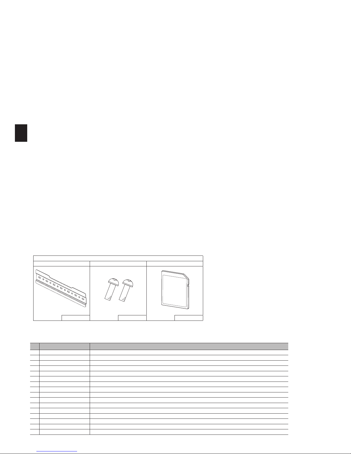
Accessories (included)
Back plate Screw M5×8 SD memory card
1 2 1
Page 3
2
Safety Notices
1
EN
WARNING
Mechanical
The hydrobox and outdoor units must not be installed, disassembled, relocated, altered or repaired by the user. Ask an authorised installer or technician. If the unit is
installed improperly or modied after installation by the user water leakage, electric shock or re may result.
The outdoor unit should be securely xed to a hard level surface capable of bearing its weight.
The hydrobox should be positioned on a hard vertical surface capable of supporting its lled weight to prevent excessive sound or vibration.
Do not position furniture or electrical appliances below the outdoor unit or hydrobox.
The discharge pipework from the emergency/safety devices of the hydrobox should be installed according to local law.
Only use accessories and replacement parts authorised by Mitsubishi Electric ask a qualied technician to t the parts.
Electrical
All electrical work should be performed by a qualied technician according to local regulations and the instructions given in this manual.
The units must be powered by a dedicated power supply and the correct voltage and circuit breakers must be used.
Wiring should be in accordance with national wiring regulations. Connections must be made securely and without tension on the terminals.
Earth unit correctly.
General
Keep children and pets away from both the hydrobox and outdoor units.
Do not use the hot water produced by the heat pump directly for drinking or cooking. This could cause illness to the user.
Do not stand on the units.
Do not touch switches with wet hands.
Annual maintenance checks on both the hydrobox and the outdoor unit should be conducted by a qualied person.
Do not place containers with liquids on top of the hydrobox. If they leak or spill onto the hydrobox damage to the unit and/or re could occur.
Do not place any heavy items on top of the hydrobox.
When installing, relocating, or servicing the hydrobox, use only the specied refrigerant (R410A) to charge the refrigerant lines. Do not mix it with any other refrigerant
and do not allow air to remain in the lines. If air is mixed with the refrigerant, then it can be the cause of abnormal high pressure in the refrigerant line, and may result
in an explosion and other hazards.
The use of any refrigerant other than that specied for the system will cause mechanical failure or system malfunction or unit breakdown. In the worst case, this could
lead to a serious impediment to securing product safety.
In heating mode, to avoid the heat emitters being damaged by excessively hot water, set the target ow temperature to a minimum of 2ºC below the maximum allowable temperature of all the heat emitters. For Zone2, set the target ow temperature to a minimum of 5ºC below the maximum allowable ow temperature of all the
heat emitters in Zone2 circuit.
Do not install the unit where combustible gases may leak, be produced, ow, or accumulate. If combustible gas accumulates around the unit, re or explosion may result.
CAUTION
Use clean water that meets local quality standards on the primary circuit.
The outdoor unit should be installed in an area with sufcient airow according to the diagrams in the outdoor unit installation manual.
The hydrobox should be located inside to minimise heat loss.
Water pipe-runs on the primary circuit between outdoor and indoor unit should be kept to a minimum to reduce heat loss.
Ensure condensate from outdoor unit is piped away from the base to avoid puddles of water.
Remove as much air as possible from water circuit.
Refrigerant leakage may cause suffocation. Provide ventilation in accordance with EN378-1.
Be sure to wrap insulation around the piping. Direct contact with the bare piping may result in burns or frostbite.
Never put batteries in your mouth for any reason to avoid accidental ingestion.
Battery ingestion may cause choking and/or poisoning.
Install the unit on a rigid structure to prevent excessive sound or vibration during operation.
If power to the hydrobox is to be turned off (or system switched off) for a long time, the water should be drained.
Preventative measures should be taken against water hammer, such as installing a Water Hammer Arrestor on the primary water circuit, as directed by the manufacturer.
In order to prevent condensation on emitters, adjust ow temperature appropriately and also set the lower limit of the ow temperature on site.
As for the handling of refrigerant, refer to the outdoor unit installation manual.
Please read the following safety precautions carefully.
WARNING:
Precautions that must be observed to prevent injuries or death.
CAUTION:
Precautions that must be observed to prevent damage to unit.
This installation manual along with the user manual should be left with the product after installation for future reference.
Mitsubishi Electric is not responsible for the failure of locally-supplied parts.
• Be sure to perform periodical maintenance.
• Be sure to follow your local regulations.
• Be sure to follow the instructions provided in this manual.
The purpose of this installation manual is to instruct competent persons how to
safely and efficiently install and commission the hydrobox system. The target
readers of this manual are competent plumbers and/or refrigeration engineers
Introduction
2
who have attended and passed the requisite Mitsubishi Electric product training
and have appropriate qualications for installation of an unvented hot water hydrobox specic to their country.
Page 4
3
Technical Information
3
EN
Product specication
Model name
EHSD-
MEC
EHSD-
MC
EHSD-
VM2C
EHSD-
YM9C
EHSC-
MEC
EHSC-
VM2C
EHSC-
VM2EC
EHSC-
VM6C
EHSC-
VM6EC
EHSC-
YM9C
EHSC-
YM9EC
EHSC-
TM9C
ERSD-
VM2C
ERSC-
MEC
ERSC-
VM2C
EHPX-
VM2C
EHPX-
VM6C
EHPX-
YM9C
Overall unit dimensions 800 × 530 × 360 mm (Height × Width × Depth)
Weight (empty) 38 kg 43 kg 44 kg 45 kg 42 kg 48 kg 43 kg 49 kg 44 kg 49 kg 44 kg 49 kg 45 kg 43 kg 49 kg 37 kg 38 kg 38 kg
Weight (full) 44 kg 49 kg 50 kg 51 kg 49 kg 55 kg 50 kg 56 kg 51 kg 56 kg 51 kg 56 kg 51 kg 50 kg 56 kg 42 kg 43 kg 43 kg
Water volume of heating circuit in the unit 5.2 kg 5.2 kg 5.2 kg 5.2 kg 6.1 kg 6.1 kg 6.1 kg 6.1 kg 6.1 kg 6.1 kg 6.1 kg 6.1 kg 5.5 kg 6.4 kg 6.4 kg 4.5 kg 4.5 kg 4.5 kg
Plate heat exchanger (MWA2) — — — —
— — — —
Plate heat exchanger (MWA1)
— — — — — — — — — — — — —
Cooling mode NOT available Available NOT available
Unvented expansion
vessel(Primary heating)
Nominal volume — 10 L — 10 L — 10 L — 10 L — 10 L — 10 L
Charge pressure — 1 bar — 1 bar — 1 bar — 1 bar — 1 bar — 1 bar
Safety
device
Water
circuit
(Primary)
Control thermistor 1 - 80°C
Pressure relief valve 0.3 MPa (3bar)
Flow sensor Min. ow 5.0 L/min
Booster
heater
Manual reset thermostat — 90°C — 90°C — 90°C
Thermal Cut-out (for dry run prevention) — 121°C — 121°C — 121°C
Primary circuit circulating Pump Grundfos UPM2 15-70 130 Grundfos UPM2K 15-75 130 Grundfos UPM2 15-70 130
Connections
Water 28mm compression (primary circuit) G1 (Male)
28mm compression
(primary circuit)
Refrigerant
(R410A)
Liquid 6.35 mm 9.52 mm 6.35 mm 9.52 mm —
Gas 12.7 mm 15.88 mm 12.7 mm 15.88 mm —
Target temperature
range
Flow
temperature
Heating 25 - 60°C
Cooling — 5 - 25°C —
Room
temperature
Heating 10 - 30 °C
Cooling — NOT available —
Guaranteed operat-
ing range
Ambient *1 0 - 35°C (
80 %RH)
Outdoor
temperature
Heating See outdoor unit spec table.
Cooling —
See outdoor unit spec table
(min. 10°C). *2
—
Electrical data
Control board
Power supply
(Phase, voltage, fre-
quency)
~/N, 230 V, 50 Hz
Breaker
(*when powered from
independent source)
10A
Booster
heater
Power supply
(Phase, voltage, fre-
quency)
— —
~/N, 230 V,
50 Hz
3~, 400 V,
50 Hz
—
~/N, 230 V,
50 Hz
~/N, 230 V,
50 Hz
~/N, 230 V,
50 Hz
~/N, 230 V,
50 Hz
3~, 400 V,
50 Hz
3~, 400 V,
50 Hz
3~, 230 V,
50 Hz
~/N, 230 V,
50 Hz
—
~/N, 230 V,
50 Hz
~/N, 230 V,
50 Hz
~/N, 230 V,
50 Hz
3~, 400 V,
50 Hz
Capacity — — 2kW
3kW
+6kW
— 2kW 2kW
2kW
+4kW
2kW
+4kW
3kW
+6kW
3kW
+6kW
3kW
+6kW
2kW — 2kW 2kW
2kW
+4kW
3kW
+6kW
Current — — 9 A 13A — 9 A 9 A 26 A 26 A 13A 13A 23A 9 A — 9 A 9 A 26 A 13A
Breaker — — 16 A 16A — 16 A 16 A 32 A 32 A 16A 16A 32A 16 A — 16 A 16 A 32 A 16A
Sound pressure level 28 dB(A)
Sound power level 40 dB(A)
Optional extras
●Wireless Remote Controller PAR-WT50R-E ●
Tank thermistor (THW5) (30 m)
PAC-TH011TKL-E *1 The environment must be frost-free.
●Wir ele ss Receiver PAR-WR51R-E ●Ther misto r PAC-TH011-E *2 Cooling mode is not available in low outdoor temperature.
●Remote Sensor PAC-SE41TS-E ●High temperature thermistor PAC-TH011HT-E
●Tank thermistor (THW5) (5 m) PAC-TH011TK-E ●ecodan Wi-Fi Interface PAC-WF010-E
●Joint pipe (ø15.88 → ø12.7) PAC-SH50RJ-E ●2 zone kit PAC-TZ01-E
●Joint pipe (ø9.52 → ø6.35) PAC-SH30RJ-E
<Table 3.1>
Page 5
4
Technical Information
3
EN
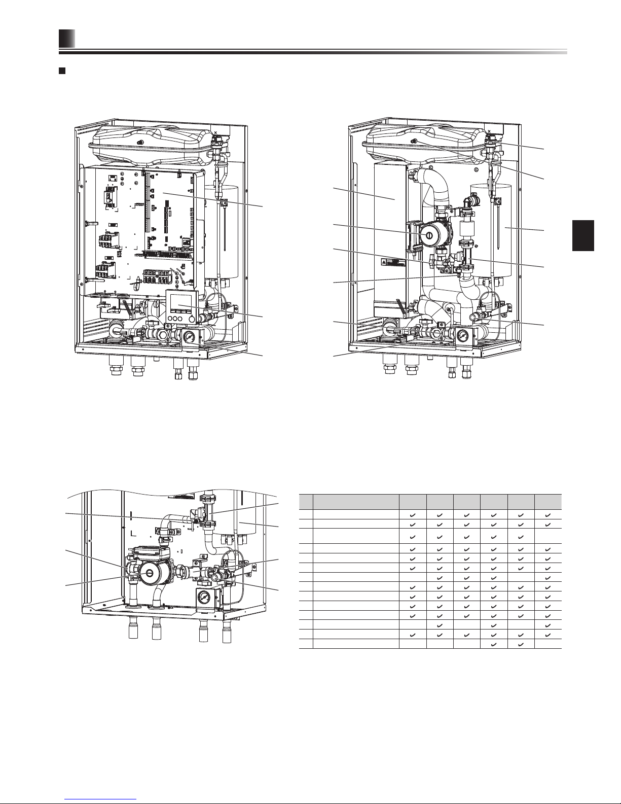
Component Parts
1
2
9
11
7
8
10
8
7
10
13
12
3
4
5
13
14
5
4
6
6
<E*S*-*M**C> (Split model system)
<EHPX-*M*C> (Packaged model system)
*For installation of E*S*-*M*EC model, make sure to install a primary-side expansion vessel in the eld. (See Figure 4.3.4)
No. Part name
EHS*-MEC
EHS*-
*M*C
EHSC*M*EC
ERS*VM2C
ERSC-
MEC
EHPX-
*M*C
1 Control and electrical box
2 Main remote controller
3
Plate heat exchanger
(Refrigerant - Water)
-
4 Water circulation pump 1
5 Pump valve
6 Drain cock (Primary circuit)
7 Booster heater 1,2
- -
8 Flow sensor
9 Manometer
10 Pressure relief valve (3bar)
11 Automatic air vent
12 Expansion vessel
- - -
13 Strainer valve
14 Drain pan
- - - -
<Table 3.2>
<Figure 3.1> <Figure 3.2>
<Figure 3.3>
Page 6
5
Technical Information
3
EN
(
348)
357
291
263
242
103
461
419
334
163
124
86
78
48
242
(348)
357
291
263
134
94
133
365
308
163
223
124
461
86
48
100±5
592
800
260
530
B
H
H
A
H
G
F
E
B
A
B
I
C D
G
A G
C
(348)
461
410
395
353
310
163
124
86
48
291
263
357
242
164
58
(242)
110
D
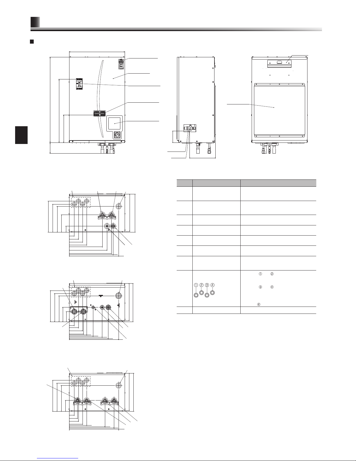
Technical Drawings
<EHS*> (Split model system)
<Front>
Automatic air vent
Front panel
Earth leakage circuit
breaker
Terminal block
Main remote controller
Pressure
relief valve
G1/2
Back panel
support
Hook
<View from below>
<View from below>
<View from below>
<Side> <Rear>
<ERS*> (Split model system for heating and cooling)
<EHPX> (Packaged model system)
<Unit: mm>
Letter Pipe description Connection size/type
A
Space heating/Indirect
DHW tank (primary) return
connection
28 mm/Compression (EHS*-*and EHPX-*)
G1 nut (ERS*-*)
B
Space heating/Indirect
DHW tank (primary) ow
connection
28 mm/Compression (EHS*-*and EHPX-*)
G1 nut (ERS*-*)
C Refrigerant (Liquid)
6.35 mm/Flare (E*SD-*)
9.52 mm/Flare (E*SC-*)
D Refrigerant (Gas)
12.7 mm/Flare (E*SD-*)
15.88 mm/Flare (E*SC-*)
E
Flow connection from heat
pump
28 mm/Compression (EHPX-*)
F
Return connection to heat
pump
28 mm/Compression (EHPX-*)
G
Discharge pipe (by installer) from pressure relief
valve
G1/2” female (valve port within hydrobox
casing)
H
Electrical cable inlets
For inlets and , run high-voltage wires
including power cable, indoor-outdoor
cable, and external output wires.
For inlets
and , run low-voltage
wires including external input wires and
thermistor wires.
For a wireless receiver (option) cable,
use inlet
.
I Drain socket
O.D. ø20
<Table 3.3>
Page 7
6
Technical Information
3
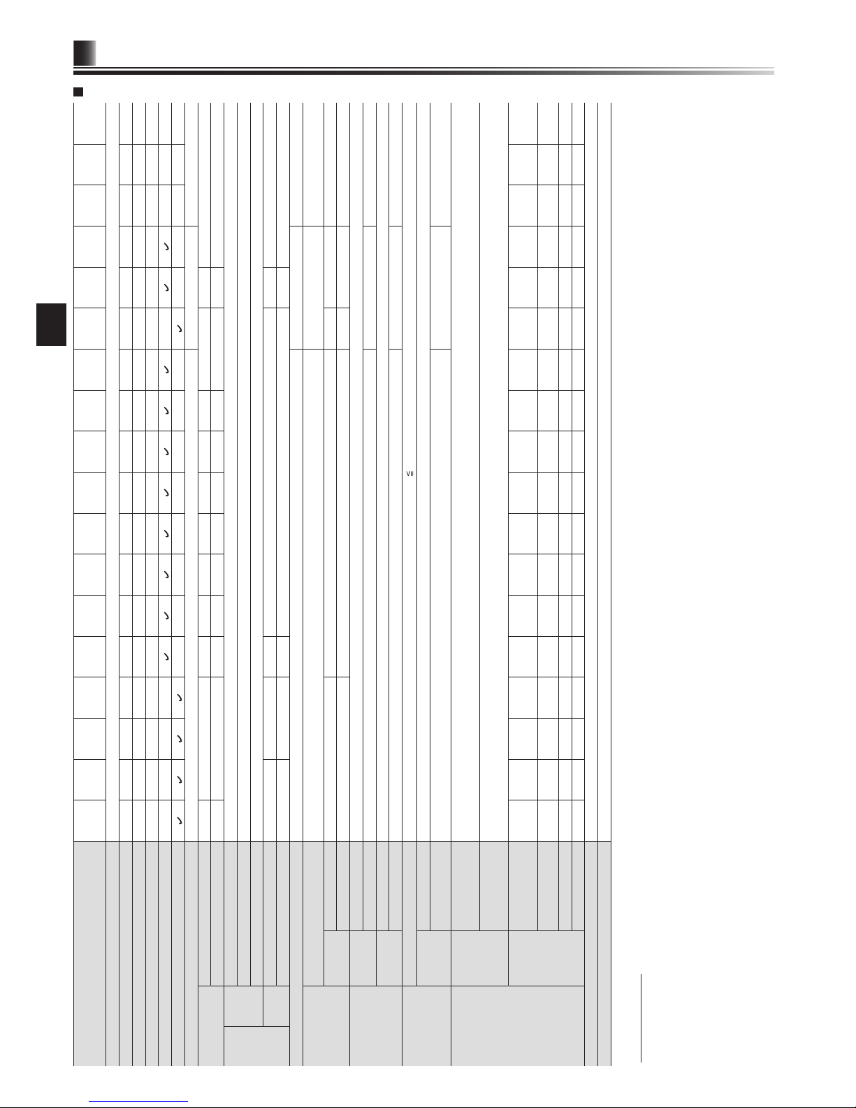
EN
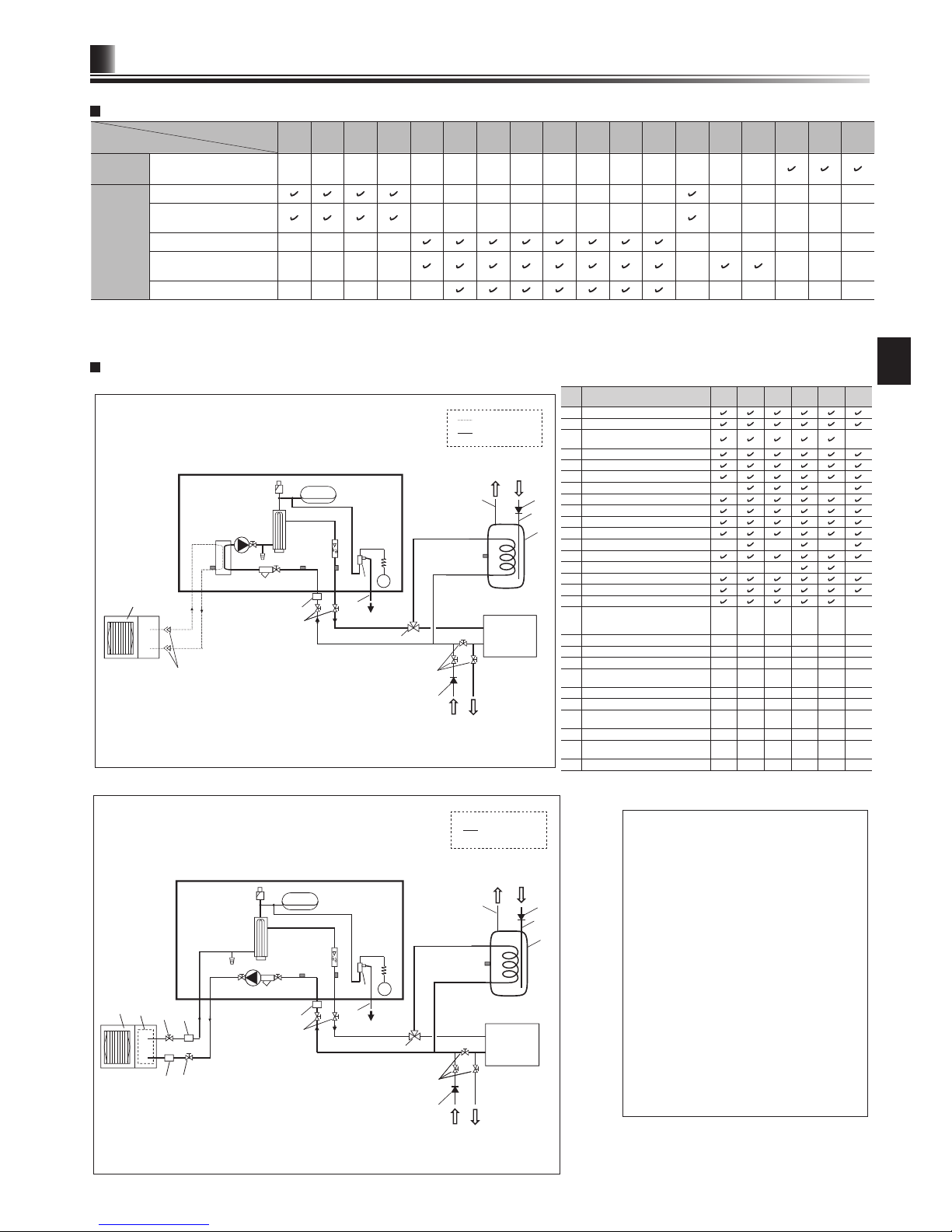
Unit Compatibility
Hydrobox
Outdoor unit
EHSD-
MEC
EHSD-MCEHSD-
VM2C
EHSD-
YM9C
EHSC-
MEC
EHSC-
VM2C
EHSC-
VM2EC
EHSCVM6C
EHSCVM6EC
EHSC-
YM9C
EHSC-
YM9EC
EHSC-
TM9C
ERSD-
VM2C
ERSC-
MEC
ERSCVM2C
EHPX-
VM2C
EHPX-
VM6C
EHPX-
YM9C
Packagedtype
PUHZ-W50, 85, 112
PUHZ-HW112, 140
― ― ― ― ― ― ― ― ― ― ― ― ― ― ―
Split-type
SUHZ-SW45
― ― ― ― ― ― ― ― ― ― ― ― ―
PUHZ-SW40, 50, 75
(See below.)
― ― ― ― ― ― ― ― ― ― ― ― ―
PUHZ-FRP71
― ― ― ― ― ― ― ― ― ―
PUHZ-SW75, 100, 120
PUHZ-SHW80, 112, 140
― ― ― ― ― ― ― ―
PUMY-P112, 125, 140*KM*2
― ― ― ― ― ― ― ― ― ― ―
<Table 3.4>
<Figure 3.4>
<Figure 3.5>
Note
• Be sure to follow your local regulations to perform system conguration of the DHW connections.
• DHW connections are not included in the hydrobox package. All required parts are to be
sourced locally.
• To enable draining of the hydrobox an isolating
valve should be positioned on both the inlet and
outlet pipework.
• Be sure to install a strainer on the inlet pipe
work to the hydrobox.
• Suitable drain pipework should be attached to
all relief valves in accordance with your country's regulations.
• A backow prevention device must be installed
on water supply pipework (IEC 61770).
• When using components made from different
metals or connecting pipes made of different
metals insulate the joints to prevent a corrosive
reaction taking place which will damage the
pipework.
Pa
18
22
25
23
24
*1
26
7
6
5
8
9
10
11
12
13
15
16
20
21
27
3
19
26
28
28
4
25
26
26
Water circuit diagram
Pa
18
19
22
25
23
24
5
3
17
9
10
11
12
13
15
16
20
27
4
6
7
8
*1
25
26
26
21
<EHS*> (Split model system)
<ERS*> (Split model system for heating and cooling)
<EHPX> (Packaged model system)
Local
system
Refrigerant pipe
Water
supply
Water
supply
DHW
DHW
Drain
Drain
Drain
Drain
Cold
water
Cold
water
Water pipe
Water pipe
Hydrobox
Hydrobox
Flare connections
Local
system
No. Part name
EHS*MEC
EHS**M*C
EHSC*M*EC
ERS*VM2C
ERSCMEC
EHPX*M*C
1 Control and electrical box
2
Main remote controller
3
Plate heat exchanger
(Refrigerant - Water)
-
4
Water circulation pump 1
5
Pump valve
6
Drain cock (Primary circuit)
7
Booster heater 1, 2
- -
8
Flow sensor
9
Manometer
10
Pressure relief valve (3 bar)
11
Automatic air vent
12
Expansion vessel
- - -
13
Strainer valve
14
Drain pan
- - - -
15
THW1
16
THW2
17
TH2
-
18
THW5
(Optional part PAC-TH011TK-E
or PAC-TH011TKL-E)
- - - - - -
19
Outdoor unit
- - - - - -
20
Drain pipe (Local supply)
- - - - - -
21
3-way valve (Local supply)
- - - - - -
22
DHW indirect unvented tank
(Local supply)
- - - - - -
23
Cold water inlet pipe (Local supply)
- - - - - -
24
DHW outlet pipe (Local supply)
- - - - - -
25
Back ow prevention device
(Local supply)
- - - - - -
26
Isolating valve (Local supply)
- - - - - -
27
Magnetic lter (Local supply)
(Recommended)
- - - - - -
28
Strainer (Local supply)
- - - - - -
<Table 3.5>
*1 Refer to the following section [Local system].
● When connecting E*SD-* to PUHZ-SW75, the following refrigerant joint pipes are necessary.
PAC-SH50RJ-E (ø15.88 → ø12.7 for gas refrigerant pipe)
PAC-SH30RJ-E (ø9.52 → ø6.35 for liquid refrigerant pipe)
Page 8
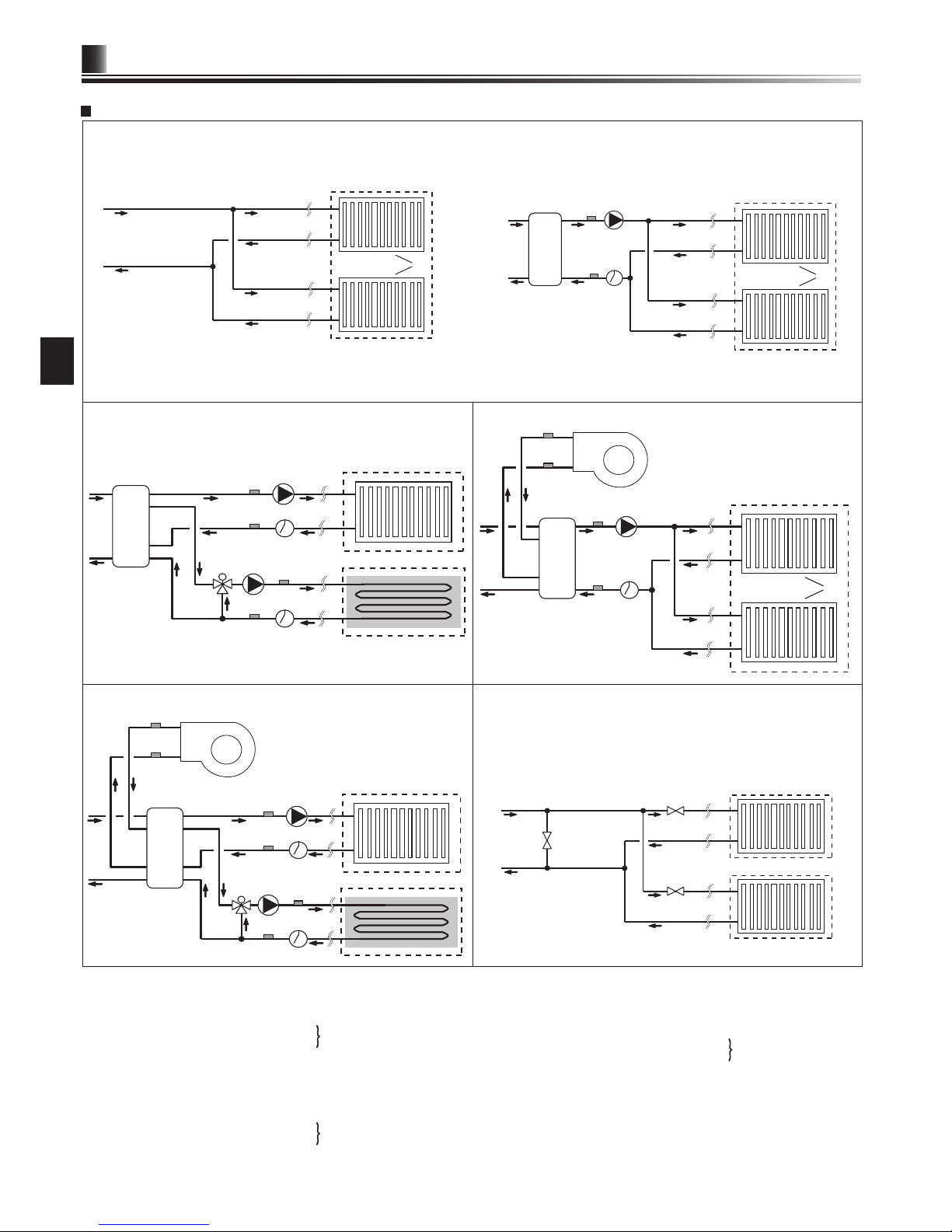
1-zone temperature control
2-zone temperature control 1-zone temperature control with boiler
2-zone temperature control with boiler
1-zone temperature control (2-zone valve ON/OFF control)
7
Technical Information
3
EN
Local system
3
7
5
2
4
6
8
9
11
11
1
12
10
11
Zone1
Zone2
1
2
3
5
6
4
Zone1
1
5
4
3
6
2
13
14
15
Zone1
2
13
14
15
7
5
4
3
6
1
8
9
10
11
12
Zone1
Zone2
*
Flow switch specications: 12V DC / 1 mA / Both normally-open and normally-closed types can be used. (Set DIP switch 3 to select the logics. Refer to “ 5.1 DIP switch function”.)
1. Zone1 heat emitters (e.g. radiator, fan coil unit) (local supply)
2. Mixing tank (local supply)
3. Zone1 ow water temp. thermistor (THW6)
4. Zone1 return water temp. thermistor (THW7)
5. Zone1 water circulation pump (local supply)
6. Zone1 ow switch (local supply) *
7. Motorized mixing valve (local supply)
8. Zone2 ow water temp. thermistor (THW8)
9. Zone2 return water temp. thermistor (THW9)
Optional part : PAC-TH011-E
Optional part : PAC-TH011-E
10. Zone2 water circulation pump (local supply)
11. Zone2 ow switch (local supply) *
12. Zone2 heat emitters (e.g. underoor heating) (local supply)
13. Boiler ow water temp. thermistor (THWB1)
14. Boiler return water temp. thermistor (THWB2)
15. Boiler (local supply)
16. Zone1 2-way valve (local supply)
17. Zone2 2-way valve (local supply)
18. Bypass valve (local supply)
Optional part : PAC-TH011HT-E
1
Zone1
16
18
Zone1
Zone2
17
Page 9

8
Technical Information
3
EN
Energy monitor
End user can monitor accumulated*1 ‘Consumed electrical energy’ and ‘Delivered heat energy’ in each operation mode*2 on the main remote controller.
*1 Monthly and Year to date
*2 - DHW operation
- Space heating
- Space cooling
Refer to “5.10 Main remote controller” for how to check the energy, and “5.1 DIP switch functions” for the details on DIP-SW setting.
Either one of the following two method is used for monitoring.
Note: Method 1 should be used as a guide. If a certain accuracy is required, the 2nd method should be used.
1. Calculation internally
Electricity consumption is calculated internally based on the energy consumption of outdoor unit, electric heater, water pump(s) and other auxiliaries. (*3)
Delivered heat is calculated internally by multiplying delta T (Flow and Return temp.) and flow rate measured by the factory fitted sensors.
Set the electric heater capacity and water pump(s) input according to indoor unit model and specs of additional pump(s) supplied locally. (Refer to the menu tree in “5.10
Main remote controller”)
Booster heater1 Booster heater2
Immersion
heater*1
Pump1*2 Pump2 Pump3
Default 2kW 4kW 0kW
***(factory tted pump)
0kW 0kW
EHSD-MEC 0kW 0kW 0kW *1 ***
When additional pumps supplied locally are
connected as Pump2/3, change setting according to specs of the pumps.
EHSD-MC 0kW 0kW 0kW *1 ***
EHSD-VM2C 2kW 0kW 0kW *1 ***
EHSD-YM9C 3kW 6kW 0kW *1 ***
EHSC-MEC 0kW 0kW 0kW *1 ***
EHSC-VM2C 2kW 0kW 0kW *1 ***
EHSC-VM2EC 2kW 0kW 0kW *1 ***
EHSC-VM6C 2kW 4kW 0kW *1 ***
EHSC-VM6EC 2kW 4kW 0kW *1 ***
EHSC-YM9C 3kW 6kW 0kW *1 ***
EHSC-YM9EC 3kW 6kW 0kW *1 ***
EHSC-TM9C 3kW 6kW 0kW *1 ***
ERSD-VM2C 2kW 0kW 0kW *1 ***
ERSC-MEC 0kW 0kW 0kW *1 ***
ERSC-VM2C 2kW 0kW 0kW *1 ***
EHPX-VM2C 2kW 0kW 0kW *1 ***
EHPX-VM6C 2kW 4kW 0kW *1 ***
EHPX-YM9C 3kW 6kW 0kW *1 ***
<Table 3.6>
*1 Change setting to 3kW when connecting optional immersion heater "PAC-IH03V2-E".
*2 "***" displayed in the energy monitor setting mode means the factory tted pump is connected as Pump 1 so that the input is automatically calculated.
*3 When the hydrobox is connected with a PUHZ-FRP or PUMY models, electricity consumption is not calculated internally. To display the electricity consumption, conduct
the 2nd method.
When anti-freeze solution (propylene glycol) is used for primary water circuit, set the delivered energy adjustment if necessary.
For further detail of above, refer to “5.10 Main remote controller”.
2. Actual measurement by external meter (locally supplied)
FTC has external input terminals for 2 ‘Electric energy meters’ and a ‘Heat meter’.
If two ‘Electric energy meters’ are connected, the 2 recorded values will be combined at the FTC and shown on the main remote controller.
(e.g. Meter 1 for H/P power line, Meter 2 for heater power line)
Refer to the [Signal inputs] section in “5.2 Connecting inputs/outputs” for more information on connectable electric energy meter and heat meter.
Page 10
a
b
b
d
c
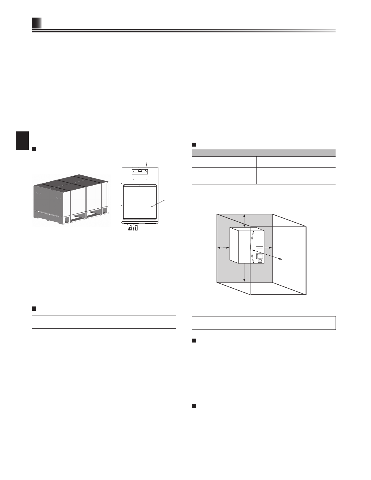
9
EN
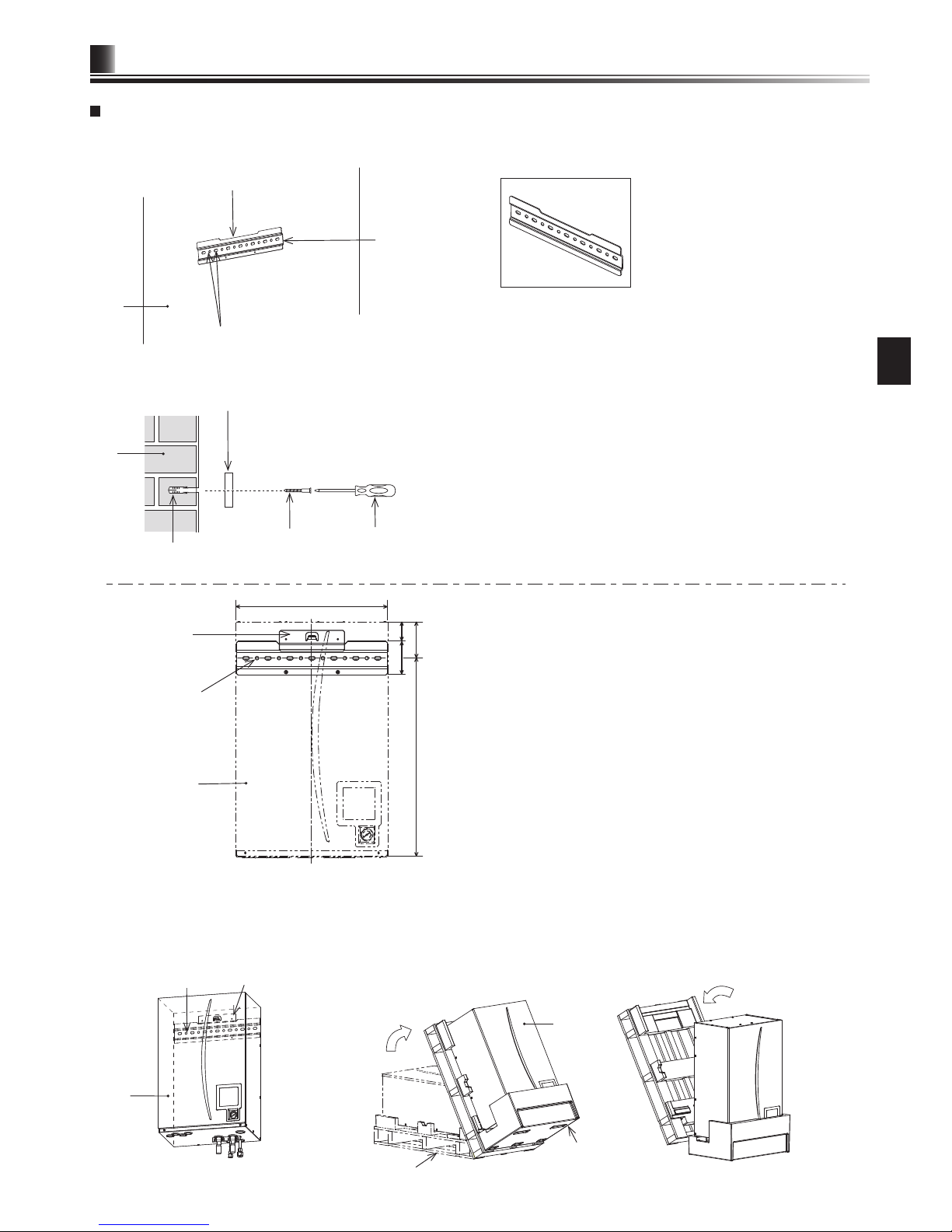
Hydrobox is delivered on a wooden pallet base with cardboard protection.
<Figure 4.1.3>
Service access
<Figure 4.1.2><Figure 4.1.1>
Hook
Back panel
support
<Preparation before the installation and service>
● Prepare the proper tools.
● Prepare the proper protection.
● Allow parts to cool before attempting any maintenance.
● Provide adequate ventilation.
● After stopping the operation of the system, turn off the power-supply breaker and remove the power plug.
● Discharge the capacitor before commencing work involving the electric parts.
<Precautions during service>
● Do not perform work involving electric parts with wet hands.
● Do not pour water or liquid into the electric parts.
● Do not touch the refrigerant.
● Do not touch the hot or cold surfaces in the refrigerant cycle.
● When the repair or the inspection of the circuit needs to be carried out without turning off the power, exercise great caution not to touch any live parts.
Installation
4
4.1 Location
Transportation and Handling
Care should be taken when transporting the hydrobox so that the casing is not
damaged by impact. Do not remove the protective packaging until hydrobox has
reached its nal location. This will help protect the structure and control panel.
Note:
• The hydrobox should ALWAYS be moved by a minimum of 2 people.
• Do NOT hold piping when moving the hydrobox.
Suitable Location
Before installation the hydrobox should be stored in a frost-free weatherproof
location. Units must NOT be stacked.
• The hydrobox should be installed indoors in a frost free weather proof location.
• The hydrobox should be positioned on a level wall capable of supporting it’s
lled weight.
• To nd out the weight, refer to “3. Technical Information”.
• Care should be taken that minimum distances around and in front of the unit for
service access are observed <Figure 4.1.3>.
• Secure the hydrobox to prevent it being knocked over.
• The hook and panel supports should be used to x the hydrobox to the wall.
<Fig. 4.1.2>
• Install the hydrobox where it is not exposed to water/excessive moisture.
Service access diagrams
Service access
Parameter Dimension (mm)
a 200
b 150
c 500
d 500
<Table 4.1.1>
Sufcient space MUST be left for the provision of discharge pipework as detailed
in National and Local building regulations.
The hydrobox must be located indoors and in a frost-free environment, for
example in a utility room.
Room Thermostat
If tting a new room thermostat for this system;
• Position it out of direct sunlight and draughts
• Position it away from internal heat sources
• Position it in a room without a TRV on the radiator/heat emittor
• Position it on an internal wall
Note: Do not position the thermostat excessively close to the external wall. The
thermostat may detect the temperature of the wall, which could affect
appropriate control of the room temperature.
• Position it approx. 1.5 m above oor level
Repositioning hydrobox
If you need to move the hydrobox to a new position FULLY DRAIN it before moving to avoid damage to the unit.
Note: Do NOT hold piping when moving the hydrobox.
Page 11
530
123
65
116
677
10
Installation
4
EN
Back plate
Wall
Screw mounting holes
Notch
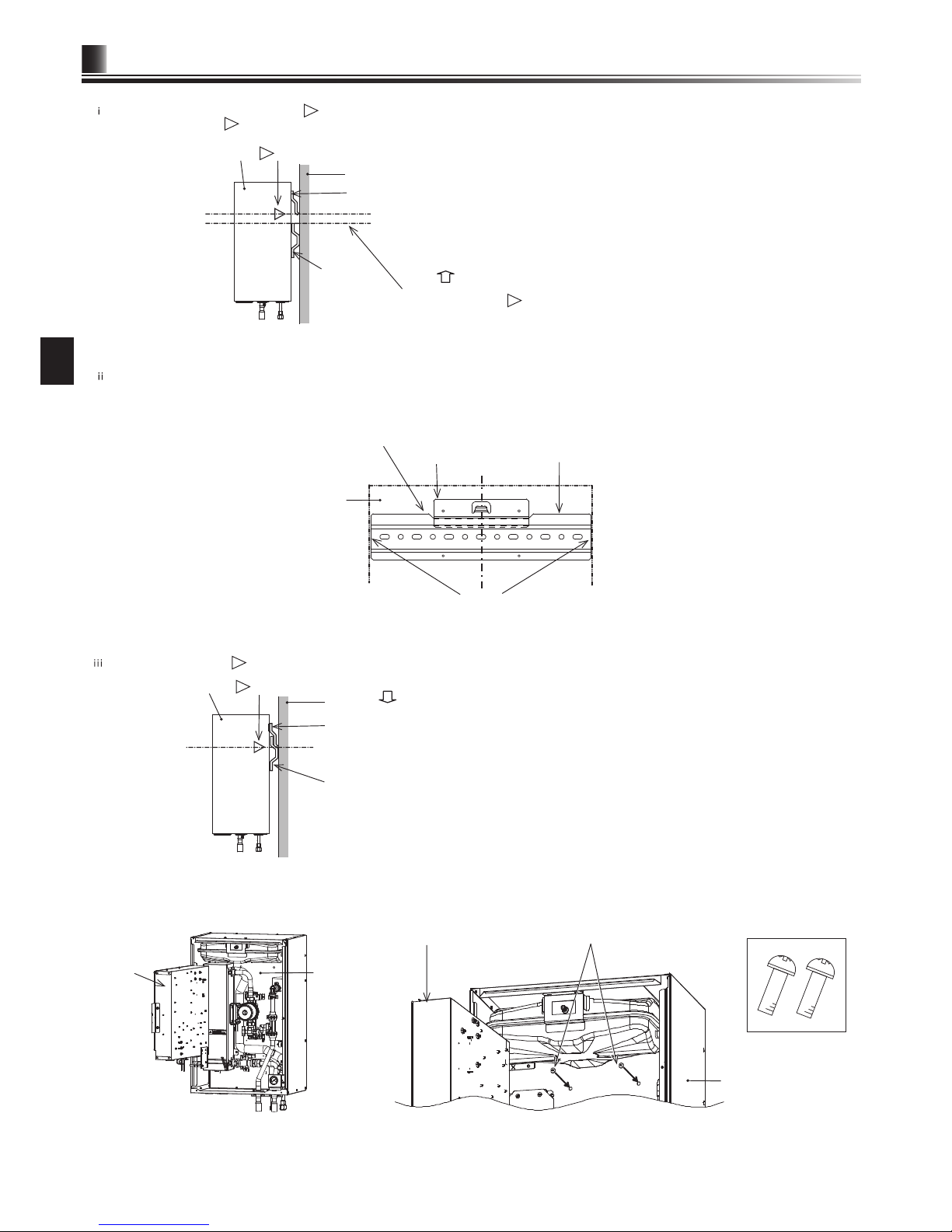
Mounting procedure
1. Install the included back plate accessory.
* When installing the back plate, use locally-supplied screws and compatible xing plugs.
● Figure 4.1.6 shows the relative positions between the unit and the wall secured
back plate.
Referring to the <Figure 4.1.3> Service access, install the back plate.
● Ensure that the notch is positioned at the TOP of the back plate.
The back plate is provided with screw mounting holes that are round or oval.
To prevent the unit from falling off the wall, choose the appropriate number
of holes or hole positions and horizontally secure the back plate to the
appropriate wall location.
Back plate
<Accessory>
Unit
Hook
(on the back
of casing)
Back plate
<Front view of unit>
Hook
Unit
Back plate
2. Insert the hook on the back of the hydrobox behind the notch of the back plate.
*The lifting up of the hydrobox is facilitated by rst tilting the unit forward using the included packaging cushioning.
Note: Hold the MAIN BODY of the hydrobox when carrying or mounting the hydrobox to a wall.
Holding and supporting the unit by the manometer, water pipe, or refrigerant pipe may result in breakdown of the components and impact on unit’s conditions of warranty.
Packaging cushion
Unit
Wooden packaging base
Tilting the unit.
<Front view>
<Side view>
Wall
Plugs
Back plate (horizontal)
Screws
Screwdriver
<Figure 4.1.4>
<Figure 4.1.5>
<Figure 4.1.6>
<Figure 4.1.7>
<Figure 4.1.8>
Centre line
Removing the wooden
packaging base.
<Process 1>
<Process 2>
<Unit: mm>
Page 12
11
Installation
4
EN
Unit
Control and
electrical
box
Unit
Control and electrical box
Fix the unit using the 2 screws.
* If it is difcult to access with power
tool, use hand tool instead.
) The back plate and the unit share the same width.
When mounting the unit, the centre lines of the back plate and the unit can be aligned by keeping the right and left edges of the back plate within the width of the unit.
The hook on the unit can then be attached to the notch on the back plate. (When mounting, the casing’s lower panel support should be in contact with the wall surface.)
<Front view of unit>
) Check and ensure that the mark is positioned and properly engaged at the bent section level on the back plate as shown.
Unit
Hook
To assist in xing the unit’s hook on to the notch
on the back plate, rst line up the centre lines.
Centre line
Side edges of the back plate
Back plate
* Keep the edges of the back plate within
the width of the unit.
3. Referring to "How to access Internal Components and Control and Electrical Box", x the unit and the back plate using the included 2 screws (accessory items).
Caution) BEFORE performing eld piping, be sure to t and tighten these two screws.
Otherwise, the hook could be disengaged, and the unit could fall down.
<Accessory>
Screw M5×8
Mount the unit.
Unit
mark
Hook
Back plate
Bent section of back plate
) Each of the right and left side panels has a mark indication.
Lift up the unit so that the
marks are positioned above the top edge of the back plate as shown below.
Lift up the unit so that the
marks are
positioned above the top edge of the back plate.
Lift up the unit.
Unit
mark
Wall
Hook
Back plate
(wall mounted)
Top edge of back plate
<Figure 4.1.9>
Wall
<Figure 4.1.10>
<Figure 4.1.11>
<Figure 4.1.12>
<Figure 4.1.13>
<Side view of unit>
Page 13
12
Installation
4
EN
Screws
<A> <B>
Hinges
Open
<Figure 4.2.1>
Screws
4.2 Water Quality and System Preparation
General
•
The water in both primary and sanitary circuit should be clean and with pH value of 6.5-8.0.
• The followings are the maximum valves;
Calcium: 100mg/L, Ca hardness: 250mg/L
Chlorine: 100mg/L, Copper: 0.3mg/L
Iron/Manganese: 0.5mg/L
• Other constituents should be to European Directive 98/83 EC standards.l
• In known hard water areas, to prevent/minimise scaling, it is benecial to restrict
the routine stored water temperature (DHW max. temp.) to 55°C.
Anti-Freeze
Anti-freeze solutions MUST use propylene glycol with a toxicity rating of Class 1 as
listed in Clinical Toxicology of Commercial Products, 5th Edition.
Note:
1. Ethylene glycol is toxic and must NOT be used in the primary water circuit
in case of any cross-contamination of the potable circuit.
2. For 2-zone valve ON/OFF control, propylene glycol MUST be used.
New Installation (primary water circuit)
• Before connecting outdoor unit, thoroughly cleanse pipework of building debris,
solder etc using a suitable chemical cleansing agent.
• Flush the system to remove chemical cleanser.
• For all packaged model systems, and the split model or PUMY system without
booster heater, add a combined inhibitor and anti-freeze solution to prevent
damage to the pipework and system components.
• For split model systems the responsible installer should decide if anti-freeze
solution is necessary for each site’s conditions. Corrosion inhibitor however
should always be used.
Existing Installation (primary water circuit)
• Before connecting outdoor unit the existing heating circuit MUST be chemically
cleansed to remove existing debris from the heating circuit.
• Flush the system to remove chemical cleanser.
• For all packaged model systems add a combined inhibitor and anti-freeze
solution to prevent damage to the pipework and system components.
• For split model systems the responsible installer should decide if anti-freeze
solution is necessary for each site’s conditions. Corrosion inhibitor however
should always be used.
When using chemical cleansers and inhibitors always follow manufacturer’s
instructions and ensure the product is appropriate for the materials used in
the water circuit
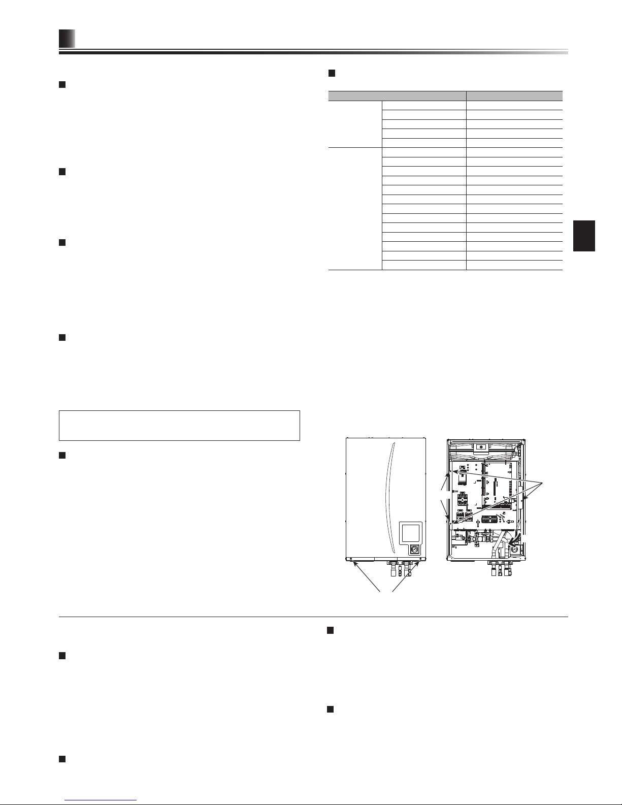
How to access Internal Components and Control
and Electrical Box
<A> Opening the front panel
1. Remove the two lower screws.
2. Slide front panel upwards slightly and open carefully.
3. Disconnect the relay connector connecting main remote controller cable and the
control board cable.
<B> Accessing the back of the control and electrical box
The control and electrical box has a holding screw on the right and is hinged on
the left hand side.
1. Remove the holding screws on the control and electrical box.
2.
The control and electrical box can then be swung forward on the left hand hinges.
Note:
1. Before accessing back of control and electrical box release cables from the
tie straps attached to the cross-support.
2. After servicing, re-secure all cables using straps provided. Reconnect
main remote controller cable to its relay connector. Replace front panel
and re-secure screws at base.
Minimum amount of water required in the space
heating / cooling circuit
Outdoor heat pump unit Minimum water quantity [L]
Packaged model PUHZ-W50 29
PUHZ-W85 37
PUHZ-W112 48
PUHZ-HW112 48
PUHZ-HW140 60
Split model SUHZ-SW45 17
PUHZ-SW40 17
PUHZ-SW50 22
PUHZ-FRP71 32
PUHZ-SW75 32
PUHZ-SW100 43
PUHZ-SW120 54
PUHZ-SHW80 34
PUHZ-SHW112 48
PUHZ-SHW140 60
PUMY-P112 80
PUMY-P125 80
PUMY-P140 80
<Table 4.2.1>
Note:
For 2-zone temperature control system, the value in the table above
excludes the amount of stored water in zone2.
4.3 Water Pipe Work
Note: Prevent the eld piping from straining the piping on the hydrobox by
xing it to a wall or applying other methods.
Hot Water Pipework
The function of the following safety components of the hydrobox should be
checked on installation for any abnormalities;
• Pressure relief valve
• Expansion vessel pre-charge (gas charge pressure)
The instruction on the following pages regarding safe discharge of hot water from
Safety devices should be followed carefully.
• The pipework will become very hot, so should be insulated to prevent burns.
• When connecting pipework, ensure that no foreign objects such as debris or the
like do not enter the pipe.
Hydraulic Filter Work (ONLY EHPX series)
Install a hydraulic lter or strainer (local supply) at the water intake (“Pipe E” in
Table 3.3, also see associated schematic Fig. 3.5)
Pipework Connections
Connections to the hydrobox should be made using the 28 mm compression as
appropriate. (except for ERSC series)
Do not over-tighten compression ttings as this will lead to deformation of the olive
ring and potential leaks.
Note: To weld the pipes in the eld, cool the pipes on the hydrobox using wet
towel etc.
ERSC series have G1 (male) thread connections.
Insulation of Pipework
•
All exposed water pipework should be insulated to prevent unnecessary heat loss
and condensation. To prevent condensate entering the hydrobox, the pipework
and connections at the top of the hydrobox should be carefully insulated.
• Cold and hot water pipework should not be run close together where possible, to
avoid unwanted heat transfer.
•
Pipework between outdoor heat pump unit and hydrobox should be insulated with
suitable pipe insulation material with a thermal conductivity of ≤ 0.04 W/m.K.
Page 14

13
Installation
4
EN
<Figure 4.3.1>
<Figure 4.3.2>
Locally supplied
drain pipe
(VP-20)
Apply polyvinyl chloride
type adhesive
Drain socket
Do not pour water into these openings.
Drain Pipework (ONLY ERSC and ERSD series)
The drain pipe should be installed to drain condensing water in Cooling mode.
• Securely install the drain pipe to prevent leakage from the connection.
• Securely insulate the drain pipe to prevent water dripping from the locally supplied
drain pipe.
• Install the drain pipe at a down slope of 1/100 or more.
• Do not place the drain pipe in drain channel where sulfuric gas exists.
• After installation, check that the drain pipe drains water properly from the outlet of
the pipe.
<Installation>
1. Apply polyvinyl chloride type adhesive over the shaded surfaces inside of the
drain pipe and on the exterior of the drain socket as shown.
2. Insert the drain socket deeply into the drain pipe <Figure 4.3.1>.
Note: Securely support the locally supplied drain pipe using pipe support to
avoid the drain pipe falling from the drain socket.
To prevent dirty water from draining directly onto the oor next to hydrobox,
please connect appropriate discharge pipework from the hydrobox.
<Checking Drainage>
• Check that the drain pipe drains water properly from the outlet of the pipe.
• Check for no leakage from the connection.
Note: Always check drainage at installation regardless of season.
•
Remove the front panel and pour water of 1 litter into the drain pan <Figure 4.3.2>.
Note: Pour water slowly into the drain pan so that water does not overow
from the drain pan.
Filling the System (Primary Circuit)
1. Check and charge expansion vessel.
2. Check all connections including factory tted ones are tight.
3. Insulate pipework between hydrobox and outdoor unit.
4.
Thoroughly clean and ush, system of all debris. (see section 4.2 for instruction.)
5. Fill hydrobox with potable water. Fill primary heating circuit with water and
suitable anti-freeze and inhibitor as necessary. Always use a lling loop with
double check valve when lling the primary circuit to avoid back ow
contamination of water supply.
• Anti-freeze should always be used for packaged model systems (see
section 4.2 for instruction). It is the responsibility of the installer to decide
if anti-freeze solution should be used in split model systems depending
on each site’s conditions. Corrosion inhibitor should be used in both split
model and packaged model systems.
Figure 4.3.3 shows freezing temperature against anti-freeze concentration.
This figure is an example for FERNOX ALPHI-11. For other anti-freeze,
please refer to relevant manual.
• When connecting metal pipes of different materials insulate the joints to
prevent a corrosive reaction taking place which will damage the pipework.
6. Check for leakages. If leakage is found, retighten the screws onto the
connections.
7. Pressurise system to 1 bar.
8. Release all trapped air using air vents during and following heating period.
9. Top up with water as necessary. (If pressure is below 1 bar)
0
0
5
10
15
20
25
50 100 150 200 250 300 350 400
Expansion vessel sizing
Expansion vessel volume [L]
System water volume [L]
<Figure 4.3.4>
Sizing Expansion Vessels
Expansion vessel volume must t the local system water volume.
To size an expansion vessel both for the heating and cooling circuits the following
formula and graph can be used.
When the necessary expansion vessel volume exceeds the volume of an built-in
expansion vessel, install an additional expansion vessel so that the sum of the
volumes of the expansion vessels exceeds the necessary expansion vessel volume.
* For installation of an E*S*-*M*EC model, provide and install an expansion
vessel in the eld as the model does not come tted with an expansion vessel.
V =
ε × G
1 −
P¹ + 0.098
P² + 0.098
Where;
V : Necessary expansion vessel volume [L]
ε : Water expansion coefcient
G : Total volume of water in the system [L]
P¹ : Expansion vessel setting pressure [MPa]
P² : Max. pressure during operation [MPa]
Graph to the right is for the following values
ε : at 70 °C = 0.0229
P¹ : 0.1 MPa
P² : 0.3 MPa
*A 30% safety margin has been added.
<Figure 4.3.3>
0
-25
-20
-15
-10
-5
5
0
10 20 30 40 50
Freezing temperature [°C]
Anti-freeze concentration [%]
Page 15

0
10
20
30
40
50
60
70
80
0 5 10 15 20 25 30 3 5 4 0
0
10
20
30
40
50
60
70
80
0 5 10 15 20 25 30 35 4 0
0
10
20
30
40
50
60
70
80
0 5 10 15 20 25 30 35 4 0
0
10
20
30
40
50
60
70
80
0 5 10 15 20 2 5 3 0 35 40
0
10
20
30
40
50
60
70
80
0 5 1 0 15 20 25 30 35 40 45
14
Installation
4
EN
* If the water ow rate is less than 7.1 L/min, the ow rate error will be activated.
If the water ow rate exceeds 27.7 L/min, the ow speed will be greater than 1.5 m/s,
which could erode the pipes.
Water Circulation Pump Characteristics
Pump speed can be selected by main remote controller setting (see <Figure 4.3.5 -
4.3.9>).
Adjust the pump speed setting so that the ow rate in the primary circuit is appropriate for the outdoor unit installed (see Table 4.3.1). It may be necessary to add an
additional pump to the system depending on the length and lift of the primary circuit.
For outdoor unit model not listed in the <Table 4.3.1>, refer to Water ow rate
range in the specication table of outdoor unit Data Book. In such case, make sure
that the ow rate is greater than 7.1 L/min and less than 27.7 L/min.
<Second pump >
If a second pump is required for the installation please read the following carefully.
If a second pump is used in the system it can be positioned in 2 ways.
The position of the pump inuences which terminal of the FTC the signal cable
should be wired to. If the additional pump(s) have current greater than 1A please
use appropriate relay. Pump signal cable can either be wired to TBO.1 1-2 or
CNP1 but not both.
Option 1 (Space heating/cooling only)
If the second pump is being used for the heating circuit only then the signal cable
should be wired to TBO.1 terminals 3 and 4 (OUT2). In this position the pump can
be run at a different speed to the hydrobox’s in-built pump.
Option 2 (Primary circuit DHW and space heating/cooling)
If the second pump is being used in the primary circuit between the hydrobox and
the outdoor unit (Package system ONLY) then the signal cable should be wired to
TBO.1 terminals 1 and 2 (OUT1). In this position the pump speed MUST match
the speed of the hydrobox’s in-built pump.
Note: Refer to 5.2 Connecting inputs/outputs.
Outdoor heat pump unit Water ow rate range [L/min]
Packaged model PUHZ-W50 7.1-14.3
PUHZ-W85 10.0-25.8
PUHZ-W112 14.4-27.7
PUHZ-HW112 14.4-27.7
PUHZ-HW140 17.9-27.7
Split model SUHZ-SW45 7.1-12.9
PUHZ-SW40 7.1-11.8
PUHZ-SW50 7.1-17.2
PUHZ-FRP71 11.5-22.9
PUHZ-SW75 10.2-22.9
PUHZ-SW100 14.4-27.7
PUHZ-SW120 20.1-27.7
PUHZ-SHW80 10.2-22.9
PUHZ-SHW112 14.4-27.7
PUHZ-SHW140 17.9-27.7
PUMY-P112 17.9-27.7
PUMY-P125 17.9-27.7
PUMY-P140 17.9-27.7
<Table 4.3.1>
<Figure 4.3.5>
Water Circulation Pump Characteristics
EHSC series
External static pressure [kPa]
Flow rate [L/min]
Speed 5 (Default setting)
Speed 4
Speed 3
Speed 2
Speed 1
* For installation of EHPX series, set its pump speed with a pressure drop between
the hydrobox and the outdoor unit factored into the external static pressure.
<Figure 4.3.6>
EHSD series
Flow rate [L/min]
<Figure 4.3.7>
ERSC series
Flow rate [L/min]
External static pressure [kPa]
External static pressure [kPa]
<Figure 4.3.8>
ERSD series
Flow rate [L/min]
External static pressure [kPa]
<Figure 4.3.9>
EHPX series
Flow rate [L/min]
External static pressure [kPa]
Speed 5 (Default setting)
Speed 4
Speed 3
Speed 2
Speed 1
Speed 5 (Default setting)
Speed 4
Speed 3
Speed 2
Speed 1
Speed 5 (Default setting)
Speed 4
Speed 3
Speed 2
Speed 1
Speed 5 (Default setting)
Speed 4
Speed 3
Speed 2
Speed 1
Page 16

15
Installation
4
EN
<Figure 4.3.10>
Factory-fitted pressure relief valve
(G1/2” female connection)
Discharge to drain
(pipe MUST be tted by installer).
Safety Device Connections
The hydrobox contains a pressure relief valve. (see <Figure 4.3.10>) The connection size is G1/2” female. The installer MUST connect appropriate discharge
pipework from this valve in accordance with local and national regulations.
Failure to do so will result in discharge from the pressure relief valve directly into
the hydrobox and cause serious damage to the product.
All pipework used should be capable of withstanding discharge of hot water.
Relief valves should NOT be used for any other purpose, and their discharges
should terminate in a safe and appropriate manner in accordance with local regulation requirements.
Note: Beware that the manometer and the pressure relief valve are NOT
strained on its capillary side and on its inlet side respectively.
If a pressure relief valve is added, it is essential that no check valve
or isolation valve is tted between the hydrobox connection and the
added pressure relief valve (safety matter).
Piping diagram for 2-zone temperature control
Connect the pipe work and locally supplied parts according to the relevant circuit
diagram shown in Section 3. Technical Information, of this manual.
For more details on wiring, refer to “5.3 Wiring for 2-zone temperature controls”.
Note: Do not install the thermistors on the mixing tank. This could affect
correct monitoring of ow and return temperatures through each
zone.
Install the Zone2 ow temp. thermistor (THW8) near the mixing valve.
ECB1
TB1
ECB1
<Figure 4.4.1>
Breaker abbreviation Meaning
ECB1 Earth leakage circuit breaker for booster heater
TB1 Terminal block 1
4.4 Electrical Connection
All electrical work should be carried out by a suitably qualied technician. Failure
to comply with this could lead to electrocution, re, and death. It will also invalidate product warranty. All wiring should be according to national wiring regulations.
The hydrobox can be powered in two ways.
1. Power cable is run from the outdoor unit to the hydrobox.
2. Hydrobox has independent power source.
Connections should be made to the terminals indicated in the gures to the left
below depending on the phase.
Booster heater and immersion heater should be connected independently from
one another to dedicated power supplies.
Locally supplied wiring should be inserted through the inlets situated on the
base of the hydrobox. (Refer to <Table 3.3>.)
Wiring should be fed down the left hand side of the control and electrical box
and clamped in place using clips provided.
The wires should be inserted individually through the cable inlets as below.
Power line (B.H.)
Power line (I.H.) (option)
Indoor-Outdoor wire
Output wires
Signal input wires
Wireless receiver (option) wire
(PAR-WR51R-E)
Connect the outdoor unit – hydrobox connecting cable to TB1.
Connect the power cable for the booster heater to ECB1.
2 4 5
1 3 6
8
7
• Make sure that ECB1 is ON.
<1 phase> <3 phase>
B
C D
A
E
E
B
C D
A
Page 17

L
N
S1
S2
S3
S1
S2
S3
TB1
L
N
ECB1
L
N
Earth
leakage
circuit
breaker
*1, *2
Outdoor unit
Power
supply
~/N
230 V
50 Hz
Wiring
circuit
breaker or
Isolating
switch
To control
board
For
booster
heater
(Primary circuit)
Hydrobox
Wiring
circuit
breaker or
Isolating
switch
Power
supply
~/N
230 V
50 Hz
L1
L2
S1
S2
S3
S1
S2
S3
TB1
L2
L3
ECB1
N
L3
L1
L2
L1
Earth
leakage
circuit
breaker
*1, *2
Outdoor unit
Power supply
3~ 400 V 50 Hz (EH**-YM9(E)C)
3~ 230 V 50 Hz (EHSC-TM9C)
Wiring
circuit
breaker or
Isolating
switch
To control
board
For
booster
heater
(Primary circuit)
Hydrobox
Wiring
circuit
breaker or
Isolating
switch
Power
supply
3N~
400 V
50 Hz
16
Installation
4
EN
Option 1: Hydrobox powered via outdoor unit
<1 phase>
<Figure 4.4.2>
Electrical connections 1 phase
Description Power supply Capacity Breaker Wiring
Booster heater (Primary circuit) ~/N 230 V 50 Hz
2 kW 16 A *2 2.5 mm²
6 kW 32 A *2 6.0 mm²
*1 If the installed earth leakage circuit breaker does not have an over-current protection function, install a breaker with that function along the same power line.
<3 phase>
<Figure 4.4.3>
Electrical connections 3 phase
Description Power supply Capacity Breaker Wiring
Booster heater (Primary circuit)
3~ 400 V 50 Hz 9 kW 16 A *2 2.5 mm²
3~ 230 V 50 Hz 9 kW 32 A *2 6.0 mm²
Wiring
Wiring No.
× size (mm²)
Hydrobox - Outdoor unit *3 3 × 1.5 (polar)
Hydrobox - Outdoor unit earth *3 1 × Min. 1.5
Circuit
rating
Hydrobox - Outdoor unit S1 - S2 *4 230 V AC
Hydrobox - Outdoor unit S2 - S3 *4 24 V DC
*2. A breaker with at least 3.0 mm contact separation in each pole shall be provided. Use earth leakage breaker (NV).
The breaker shall be provided to ensure disconnection of all active phase conductors of the supply.
*3. Max. 45 m
If 2.5 mm² used, Max. 50 m
If 2.5 mm² used and S3 separated, Max. 80 m
*4. The values given in the table above are not always measured against the ground value.
Notes: 1. Wiring size must comply with the applicable local and national codes.
2. Indoor unit/outdoor unit connecting cords shall not be lighter than polychloroprene sheathed exible cord. (Design 60245 IEC 57)
Indoor unit power supply cords shall not be lighter than polychloroprene sheathed exible cord. (Design 60227 IEC 53)
3. Install an earth longer than other cables.
4. Please keep enough output capacity of power supply for each heater. Insufcient power supply capacity might cause chattering.
*1 If the installed earth leakage circuit breaker does not have an over-current protection function, install a breaker with that function along the same power line.
Afx label A that is included with the manuals near each wiring diagram for hydrobox and outdoor units.
Afx label A that is included with the manuals near each wiring diagram for hydrobox and outdoor units.
Page 18

S1
S2
S3
L
N
L
N
CN01
CN01
CN01
CN01
S1
S2
S3
L
N
S1
S2
S3
S1
S2
S3
TB1
L
N
ECB1
L
N
For
booster
heater
(Primary circuit)
To control
board
Outdoor unit
Wiring
circuit
breaker or
Isolating
switch
Earth
leakage
circuit
breaker
*1, *2
Power
supply
~/N
230 V
50 Hz
Power
supply
~/N
230 V
50 Hz
Earth
leakage
circuit
breaker
*1, *2
Wiring
circuit
breaker or
Isolating
switch
Wiring
circuit
breaker or
Isolating
switch
Power
supply
~/N
230V
50Hz
Hydrobox
Initial settings
(Power supplied
by outdoor unit)
Modied settings
(Separate power
supply to
the hydrobox)
BLACK
BLACK
YELLOW
BLACK
YELLOW
YELLOW
YELLOW
BLACK
Hydrobox
control board
White
White
L1
L2
S1
S2
S3
S1
S2
S3
TB1
L2
L3
ECB1
N
L3
L1
L
N
Earth
leakage
circuit
breaker
*1, *2
Outdoor unit
Power
supply
3N~
400 V
50 Hz
Wiring
circuit
breaker or
Isolating
switch
To control
board
For
booster
heater
(Primary circuit)
Hydrobox
Wiring
circuit
breaker or
Isolating
switch
Power
supply
~/N
230 V
50 Hz
Earth
leakage
circuit
breaker
*1, *2
Wiring
circuit
breaker or
Isolating
switch
Power supply
3~ 400 V 50 Hz (EH**-YM9(E)C)
3~ 230 V 50 Hz (EHSC-TM9C)
Hydrobox
control board
17
Installation
4
EN
Hydrobox power supply ~/N 230 V 50 Hz
Hydrobox input capacity
Main switch (Breaker)
*2
16 A
Wiring
Wiring No.
× size (mm²)
Hydrobox power supply 2 × Min. 1.5
Hydrobox power supply earth 1 × Min. 1.5
Hydrobox - Outdoor unit *3 2 × Min. 0.3
Hydrobox - Outdoor unit earth —
Circuit
rating
Hydrobox L - N *4 230 V AC
Hydrobox - Outdoor unit S1 - S2 *4 —
Hydrobox - Outdoor unit S2 - S3 *4 24 V DC
Notes: 1. Wiring size must comply with the applicable local and national codes.
2. Indoor unit/outdoor unit connecting cords shall not be lighter than polychloroprene sheathed exible cord. (Design 60245 IEC 57)
Indoor unit power supply cords shall not be lighter than polychloroprene sheathed exible cord. (Design 60227 IEC 53)
3. Install an earth longer than other cables.
4. Please keep enough output capacity of power supply for each heater. Insufcient power supply capacity might cause chattering.
Option2: Hydrobox powered by independent source
If the hydrobox and outdoor units have separate power supplies, the following
requirements MUST be carried out:
• Change connector connections in hydrobox control and electrical box
(see Figure 4.4.4).
• Turn the outdoor unit DIP switch SW8-3 to ON.
• Turn on the outdoor unit BEFORE the hydrobox.
• Power by independent source is not available for particular models of
outdoor unit model.
For more detail, refer to the connecting outdoor unit installation manual.
<1 phase>
<Figure 4.4.5>
Electrical connections 1 phase
<Figure 4.4.4>
*1 If the installed earth leakage circuit breaker does not have
an over-current protection function, install a breaker with that
function along the same power line.
<3 phase>
<Figure 4.4.6>
Electrical connections 3 phase
*1 If the installed earth leakage circuit breaker does not have
an over-current protection function, install a breaker with that
function along the same power line.
*2. A breaker with at least 3.0 mm contact separation in each pole shall be
provided. Use earth leakage breaker (NV).
The breaker shall be provided to ensure disconnection of all active
phase conductors of the supply.
*3. Max. 120 m
*4. The values given in the table above are not always measured against
the ground value.
Afx label B that is included with the manuals near
each wiring diagram for hydrobox and outdoor units.
Afx label B that is included with the manuals near
each wiring diagram for hydrobox and outdoor units.
Description Power supply
Capacity Breaker
Wiring
Booster heater
(Primary circuit)
3~ 400 V 50 Hz 9 kW 16 A *2 2.5 mm²
3~ 230 V 50 Hz 9 kW 32 A *2 6.0 mm²
Description Power supply
Capacity Breaker
Wiring
Booster heater
(Primary circuit)
~/N 230 V 50 Hz
2 kW 16 A *2 2.5 mm²
6 kW 32 A *2 6.0 mm²
Page 19

18
System Set Up
5
EN
5.1 DIP Switch Functions
Located on the FTC printed circuit board are 5 sets of small white switches
known as DIP switches. The DIP switch number is printed on the circuit board
next to the relevant switches. The word ON is printed on the circuit board and on
the DIP switch block itself. To move the switch you will need to use a pin or the
corner of a thin metal ruler or similar.
DIP switch settings are listed below in Table 5.1.1.
Only an authorised installer can change DIP switch setting under one’s own responsibility according to the installation condition.
Make sure to turn off both indoor unit and outdoor unit power supplies before
changing the switch settings.
DIP switch Function OFF ON
Default settings:
Indoor unit model
SW1
SW1-1 Boiler WITHOUT Boiler WITH Boiler OFF
SW1-2 Heat pump maximum outlet water temperature 55ºC 60ºC ON *1
SW1-3 DHW tank WITHOUT DHW tank WITH DHW tank OFF
SW1-4 Immersion heater WITHOUT Immersion heater WITH Immersion heater OFF
SW1-5 Booster heater WITHOUT Booster heater WITH Booster heater
OFF: E***-M*C
ON : E***-*M2/6/9C
SW1-6 Booster heater function For heating only For heating and DHW
OFF: E***-M*C
ON : E***-*M2/6/9C
SW1-7 Outdoor unit type Split type Packaged type
OFF: E*S*-*M*C
ON : EHPX-*M*C
SW1-8 Wireless remote controller WITHOUT Wireless remote controller WITH Wireless remote controller OFF
SW2
SW2-1 Room thermostat1 input (IN1) logic change
Zone1 operation stop at thermostat short Zone1 operation stop at thermostat open
OFF
SW2-2 Flow switch1 input (IN2) logic change Failure detection at short Failure detection at open OFF
SW2-3 Booster heater capacity restriction Inactive Active
OFF: Except E***-VM2*C
ON : E***-VM2*C
SW2-4 Cooling mode function Inactive Active
OFF: Except ERS*-*M**C
ON : ERS*-*M**C
SW2-5
Automatic switch to backup heat source operation
(When outdoor unit stops by error)
Inactive Active *2 OFF
SW2-6 Mixing tank WITHOUT Mixing tank WITH Mixing tank OFF
SW2-7 2-zone temperature control Inactive Active *6 OFF
SW2-8 Flow sensor WITHOUT Flow sensor WITH Flow sensor ON
SW3
SW3-1 Room thermostat 2 input (IN6) logic change
Zone2 operation stop at thermostat short Zone2 operation stop at thermostat open
OFF
SW3-2 Flow switch 2 input (IN3) logic change Failure detection at short Failure detection at open OFF
SW3-3 Flow switch 3 input (IN7) logic change Failure detection at short Failure detection at open OFF
SW3-4 Electric energy meter WITHOUT Electric energy meter WITH Electric energy meter OFF
SW3-5 Heating mode function *3 Inactive Active ON
SW3-6 2-zone valve ON/OFF control Inactive Active OFF
SW3-7 Heat exchanger for DHW Coil in tank External plate HEX OFF
SW3-8 Heat meter WITHOUT Heat meter WITH Heat meter OFF
SW4
SW4-1 Multiple outdoor units control Inactive Active OFF
SW4-2 Position of multiple outdoor units control *7 Slave Master OFF
SW4-3 — — — OFF
SW4-4
Indoor unit only operation (during installation work) *4
Inactive Active OFF
SW4-5 Emergency mode (Heater only operation) Normal
Emergency mode (Heater only operation)
OFF *5
SW4-6 Emergency mode (Boiler operation) Normal Emergency mode (Boiler operation) OFF *5
SW5
SW5-1 — — — OFF
SW5-2 Advanced auto adaptation Inactive Active ON
SW5-3
SW5-4
SW5-5
SW5-6
SW5-7
SW5-8 — — — OFF
<Table 5.1.1>
Note: *1.
When the hydrobox is connected with a PUMY-P/SUHZ-SW outdoor unit of which maximum outlet water temperature is 55ºC, DIP SW1-2 must be changed to OFF.
*2. OUT11 will be available. For safety reasons, this function is not available for certain errors. (In that case, system operation must be stopped and only
the water circulation pump keeps running.)
*3 This switch functions only when the hydrobox is connected with a PUHZ-FRP outdoor unit. When another type of outdoor unit is connected, the
heating mode function is active regardless of the fact that this switch is ON or OFF.
*4. Space heating and DHW can be operated only in indoor unit, like an electric boiler. (Refer to “5.5 Indoor unit only operation”. )
*5. If emergency mode is no longer required, return the switch to OFF position.
*6. Active only when SW3-6 is set to OFF.
*7. Active only when SW4-1 is set to ON.
<Figure 5.1.1>
SW1
SW3
SW4
SW2
SW5
SW5-3 SW5-4 SW5-5 SW5-6 SW5-7
E*SC-*M*C ON ON ON ON OFF
E*SD-*M*C ON OFF OFF ON OFF
EHPX-*M*C OFF OFF OFF OFF OFF
Capacity code
Page 20

1
3
CN3C
(BLU)
1
3
CNPWM
(WHT)
LED1
LED2
LED3
LED4
CN108
5
1
5
1
5
1
CNRF
(WHT)
CN105
(RED)
TBO.1
TBO.2
TBO.3
TBO.4
CNP1
(WHT)
CNP4
(RED)
CNV1
(WHT)
CN22
(BLU)
CNIT
(BLU)
CN01
(WHT)
F2 F1
6.3A 250V 10A 250V
SW1
SW2
SW3
SW4
SW5
1
8
1
8
1
1
5
1
3
1
3
8
1
1
2
3
4
5
6
1
2
3
4
5
6
1
2
3
4
5
6
7
8
1
2
3
4
5
6
8
1
6
1
2
4
6
CNBH
(WHT)
CNBC
(GRY)
1
1
3
1
2
1
2
1
2
CNBHT
(BLK)
1
3
7
1
3
CNIH
(ORN)
1
4
1
3
CNW5
(WHT)
CN21
(YLW)
CNW12
(RED)
CN20
(RED)
TBI.2
126 10148
137 11945321
TBI.3
2 4 6 8 10 12 14
1
357 9
11
13
1
4
CN1A
(WHT)
2 4 6 8 10 12 14
1
357 9
11
13
TBI.1
19
System Set Up
5
EN
5.2 Connecting inputs/outputs
When the wires are wired to adjacent terminals
use ring terminals and insulate the wires.
<Figure 5.2.1>
FTC
Signal inputs
Item Name Model and specications
Signal input
function
Signal input
wire
Use sheathed vinyl coated cord or cable.
Max. 30 m
Wire type: CV, CVS or equivalent
Wire size: Stranded wire 0.13 mm² to 1.25 mm²
Solid wire: ø0.4 mm to ø1.2 mm
Switch Non-voltage “a” contact signals
Remote switch: minimum applicable load 12V DC, 1mA
Wiring specication and local supply parts
Thermistor inputs
Name Terminal block Connector Item Optional part model
TH1 — CN20 Thermistor (Room temp.) (Option) PAC-SE41TS-E
TH2 — CN21 Thermistor (Ref. liquid temp.) —
THW1 — CNW12 1-2 Thermistor (Flow water temp.) —
THW2 — CNW12 3-4 Thermistor (Return water temp.) —
THW5 — CNW5 Thermistor (DHW tank water temp.) (Option) *1 PAC-TH011TK-E (5 m) / PAC-TH011TKL-E (30 m)
THW6 TBI.2 3-4 — Thermistor (Zone1 ow water temp.) (Option) *1
PAC-TH011-E
THW7 TBI.2 5-6 — Thermistor (Zone1 return water temp.) (Option) *1
THW8 TBI.2 7-8 — Thermistor (Zone2 ow water temp.) (Option) *1
PAC-TH011-E
THW9 TBI.2 9-10 — Thermistor (Zone2 return water temp.) (Option) *1
THWB1 TBI.2 11-12 — Thermistor (Boiler ow water temp.) (Option) *1
PAC-TH011HT-E
THWB2 TBI.2 13-14 — Thermistor (Boiler return water temp.) (Option) *1
Ensure to wire thermistor wirings away from the power line and/or OUT1 to 15 wirings.
*1. The maximum length of the thermistor wiring is 30 m. When the wires are wired to adjacent terminals, use ring terminals and insulate the wires.
The length of the optional thermistors are 5 m. If you need to splice and extend the wirings, following points must be carried out.
1) Connect the wirings by soldering.
2) Insulate each connecting point against dust and water.
Name Terminal block Connector Item OFF (Open) ON (Short)
IN1 TBI.1 13-14 — Room thermostat 1 input *1 Refer to SW2-1 in <5.1 DIP Switch Functions>.
IN2 TBI.1 11-12 — Flow switch 1 input Refer to SW2-2 in <5.1 DIP Switch Functions>.
IN3 TBI.1 9-10 — Flow switch 2 input (Zone1) Refer to SW3-2 in <5.1 DIP Switch Functions>.
IN4 TBI.1 7-8 — Demand control input Normal Heat source OFF/ Boiler operation *3
IN5 TBI.1 5-6 — Outdoor thermostat input *2 Standard operation Heater operation/ Boiler operation *3
IN6 TBI.1 3-4 — Room thermostat 2 input *1 Refer to SW3-1 in <5.1 DIP Switch Functions>.
IN7 TBI.1 1-2 — Flow switch 3 input (Zone2) Refer to SW3-3 in <5.1 DIP Switch Functions>.
IN8 TBI.3 1-2 — Electric energy meter 1
*4IN9 TBI.3 3-4 — Electric energy meter 2
IN10 TBI.3 5-6 — Heat meter
IN11 TBI.3 7-8 —
Smart grid ready input *5
IN12 TBI.3 9-10 —
IN1A TBI.3 12-14 CN1A Flow sensor — —
*1. Set the ON/OFF cycle time of the room thermostat for 10 minutes or more; otherwise the compressor may be damaged.
*2. If using outdoor thermostat for controlling operation of heaters, the lifetime of the heaters and related parts may be reduced.
*3. To turn on the boiler operation, use the main remote controller to select “Boiler” in “External input setting“ screen in the service menu.
*4. Connectable electric energy meter and heat meter
● Pulse type Voltage free contact for 12VDC detection by FTC (TBI.3 1, 3 and 5 pins have a positive voltage.)
● Pulse duration Minimum ON time: 40ms
Minimum OFF time: 100ms
● Possible unit of pulse 0.1 pulse/kWh 1 pulse/kWh 10 pulse/kWh
100 pulse/kWh 1000 pulse/kWh
Those values can be set by the main remote controller. (Refer to the menu tree in "5.10 Main remote controller".)
*5. As for the smart grid ready, refer to "5.6 Smart grid ready".
Page 21

LN
OUT8
LN
OUT13
LN
1 2
3
4
5
6
TBO.1
1 2
3
4
5
6
TBO.2 TBO.3
1 2
3
4
5
6 7 8
1 2
3
4
6
5
TBO.4
LLL NNN
OUT1 OUT2 OUT3
N L N L
OUT5
OUT4
L N L N L
OUT10 OUT11 OUT12 OUT15
N
OUT9Close Open
20
System Set Up
5
EN
Note:
1. When the hydrobox is powered via outdoor unit, the maximum grand total current of (a)+(b) is 3.0 A.
2. Do not connect multiple water circulation pumps directly to each output (OUT1, OUT2, and OUT3). In such a case, connect them via (a) relay(s).
3. Do not connect water circulation pumps to both TBO.1 1-2 and CNP1 at the same time.
4. Connect an appropriate surge absorber to OUT10 (TBO.3 1-2) depending on the load at site.
5. Stranded wire should be processed with insulation-covered bar terminal (DIN46228-4 standard compatible type).
Item Name Model and specications
External output function Outputs wire
Use sheathed vinyl coated cord or cable.
Max. 30 m
Wire type: CV, CVS or equivalent
Wire size: Stranded wire 0.25 mm² to 1.5 mm²
Solid wire: 0.25 mm² to 1.5 mm²
Wiring specication and local supply parts
Outputs
Name Terminal block Connector Item OFF ON Signal/Max. current Max. total current
OUT1 TBO.1 1-2 CNP1 Water circulation pump 1 output
(Space heating/cooling & DHW)
OFF ON 230V AC 1.0A Max.
4.0A (a)
OUT2 TBO.1 3-4 — Water circulation pump 2 output
(Space heating/cooling for Zone1)
OFF ON 230V AC 1.0A Max.
OUT3 TBO.1 5-6 — Water circulation pump 3 output
(Space heating/cooling for Zone2) *1
OFF ON 230V AC 1.0A Max.
2-way valve 2b output *2
OUT14 — CNP4 Water circulation pump 4 output (DHW) OFF ON 230V AC 1.0A Max.
OUT4 TBO.2 4-6 CNV1 3-way valve (2-way valve 1) output Heating DHW 230V AC 0.1A Max.
3.0A (b)
OUT5
TBO.2 1-2
— Mixing valve output *1 Stop
Close
230V AC 0.1A Max.
TBO.2 2-3 Open
OUT6 — CNBH 1-3 Booster heater 1 output OFF ON 230V AC 0.5A Max. (Relay)
OUT7 — CNBH 5-7 Booster heater 2 output OFF ON 230V AC 0.5A Max. (Relay)
OUT8 TBO.4 5-6 — Cooling signal output OFF ON 230V AC 0.5A Max.
OUT9 TBO.4 3-4 CNIH Immersion heater output OFF ON 230V AC 0.5A Max. (Relay)
OUT11 TBO.3 3-4 — Error output Normal Error 230V AC 0.5A Max.
OUT12 TBO.3 5-6 — Defrost output Normal Defrost 230V AC 0.5A Max.
OUT13 TBO.4 1-2 — 2-way valve 2a output *2 OFF ON 230V AC 0.1A Max.
OUT15 TBO.3 7-8 — Comp ON signal OFF ON 230V AC 0.5A Max.
OUT10 TBO.3 1-2 — Boiler output OFF ON
non-voltage contact
· 220-240V AC (30V DC)
0.5A or less
· 10mA 5V DC or more
—
Do not connect to the terminals that are indicated as “—” in the “Terminal block” eld.
*1 For 2-zone temperature control.
*2 For 2-zone valve ON/OFF control.
<Figure 5.2.2>
Tool
Tool
Conductor
Conductor
Outline view Top view
How to use TBO.1 to 4
Connect them using either way as shown above.
5.3 Wiring for 2-zone temperature control
1. Water circulation pump 2 (Zone1 water circulation pump) / Water circulation pump 3 (Zone2 water circulation pump)
Electrically wire water circulation pumps 2 and 3 to the appropriate output terminals. (Refer to “Outputs” in 5.2.)
2. Flow switch 2 (Zone1 ow switch) / Flow switch 3 (Zone2 ow switch)
Connect ow switches 2 and 3 to the appropriate terminals. (Refer to “Signal inputs” in 5.2.)
Set DIP switches 3-2 and 3-3 according to the functions of individual ow switches 2 and 3.
(Refer to “DIP switch functions” in 5.1.)
3. Thermistor
Connect the thermistor to monitor the Zone1 ow temperature to the THW6 (TBI. 2-3 and 2-4) terminals.
Connect the thermistor to monitor the Zone1 return temperature to the THW7 (TBI. 2-5 and 2-6) terminals.
Connect the thermistor to monitor the Zone2 ow temperature to the THW8 (TBI. 2-7 and 2-8) terminals.
Connect the thermistor to monitor the Zone2 return temperature to the THW9 (TBI. 2-9 and 2-10) terminals.
The maximum length of the thermistor wiring is 30 m. The length of the optional thermistors are 5 m. If you need to
splice and extend the wirings, following points must be carried out.
1) Connect the wirings by soldering.
2) Insulate each connecting point against dust and water.
4. Motorized mixing valve
Connect three wires coming from the motorized mixing valve to the appropriate terminals referring to “Outputs” in 5.2.
Note: Connect the signal line to open Port A (hot water inlet port) to TBO. 2-3 (Open), the signal line to open
Port B (cold water inlet port) to TBO. 2-1 (Close) , and the neutral terminal wire to TBO. 2-2 (N).
N L
FTC
TBO.2
1 2
3
Close N Open
A
B
from mixing tank
to mixing tank
to Zone2
heat emitter
from Zone2
heat emitter
Motorized mixing
valve
Page 22

7 8
9
10
TBI.3
IN11 IN12
21
System Set Up
5
EN
2. DIP switch
Turn DIP switch 3-6 ON.
3. 2-way valve 2a (for Zone1) / 2-way valve 2b (for Zone2)
Electrically wire 2-way valve 2a and 2b to the appropriate external output terminals. (Refer to "External outputs" in 5.2)
5.4 2-zone valve ON/OFF control
5.5 Indoor unit only operation (during installation work)
1. Pipe work
1. Zone1 2-way valve 2a (local supply)
2. Zone2 2-way valve 2b (local supply)
3. Water circulation pump 2 (local supply) *1
4. By-pass valve (local supply) *2
*1 Install according to system in the eld.
*2 For safety protection, it is recommended to install a by-pass valve.
Note: 1. Freeze stat function is deactivated whilst this control is ON.
Use anti-freeze solution to avoid freezing, if necessary.
2. When mixing tank and DHW tank are installed, install a
3-way valve (OUT4) in the primary water circuit.
4. Room thermostat connection
Opening /closing 2-way valve provides a simple 2-Zone control.
Flow temperature is common for Zone1 and 2.
In the case when DHW or heating operation is required prior to connection of the outdoor unit; i.e. during installation work, an electric heater in indoor unit (*1) can be used.
*1 Model with electric heater only.
1. To start operation
● Check if the indoor unit power supply is OFF, and turn DIP switch 4-4 and 4-5 ON.
● Turn ON the indoor unit power supply.
2. To end operation *2
● Turn OFF the indoor unit power supply.
● Turn DIP switch 4-4 and 4-5 OFF.
*2 When the indoor unit only operation is ended, ensure to check over the settings after outdoor unit is connected.
Note:
Prolonged running of the this operation may affect the life of the electric heater.
Heating operation mode Zone1 Zone2
Room temp. control
(Auto adaptation) *3
● Wireless remote controller (option)
● Room temperature thermistor (option)
● Main remote controller (remote position)
● Wireless remote controller (option)
Compensation curve or ow temp. control ● Wireless remote controller (option) *4
● Room temperature thermostat (local supply)
● Wireless remote controller (option) *4
● Room temperature thermostat (local supply)
*3 Ensure to install the room thermostat for Zone1 in main room since the Room temp. control for Zone1 is prioritized.
*4 The wireless remote controller can be used as a thermostat.
1
3
4
2
Zone1
Zone2
In DHW or heating operation, the commands in the table below can be used.
IN11 IN12 Meaning
OFF (open) OFF (open) Normal operation
ON (short) OFF (open) Switch-on recommendation*1
OFF (open) ON (short) Switch-off command
ON (short) ON (short) Switch-on command*2
Note:
• To activate this function, settings on the main remote controller are required.
(Main menu → Service → “Function settings” Ref. add: 0, Unit: 1)
• Heating operation mode (compensation curve or ow temp. control) requires
the optional wireless remote controller.
*1 Switch-on recommendation has following 2 modes:
Mode 7 Hot water operation
Additional boost temperature is added onto the usual DHW target temperature.
(1-Inactive (default) /2-Target temp. +3°C/3-Target temp. +5°C)
Mode 8 Heating operation
Heating ON (permitted heating with thermo ON) range is extended.
(1-Inactive (default ) /2-Thermo ON temp. +2°C/3-Thermo ON temp. +3°C)
*2 Switch-on command has following 2 modes:
Hot water operation
With electrical heater or DIP SW 1-2 ON → Target temp. : 60°C
Without electrical heater and DIP SW 1-2 OFF → Target temp. : 55°C
Heating operation
Heating is ALWAYS permitted.
5.6 Smart grid ready
Page 23

TBO.2 4-5
TBO.4 1-2
DIP-SW1
Connector CNW5
22
System Set Up
5
EN
WARNING: When connecting DHW tank
(1) Attach the optional thermistor THW5 (PAC-TH011TK-E / PAC-TH011TKL-E).
(2) Always use earth leakage breaker when connecting immersion heater.
(3) When installing an immersion heater, be sure that the immersion heater has a built-in direct cut-off thermostat.
(4) Connect a pressure relief valve on the sanitary water side.
(5) It is essential that no check valve or isolating valve is tted between the hydrobox and the pressure relief valve.
5.7 Installation procedure for DHW tank
Note:
• Be aware that the respective DHW operations are greatly effected by the
selections of the components such as tank, immersion heater, or the
like.
• Follow your local regulations to perform system conguration.
1. To enable switching of the water circulation circuit between the DHW mode
and the heating mode, install a 3-way valve (local supply). The 3-way valve
and the DHW tank should be positioned as shown in the system diagram on
the page 6, Figure 3.4 or 3.5 as applicable.
The use of two 2-way valves can perform the same function as a 3-way valve.
2. Install the optional thermistor THW5 (optional part PAC-TH011TK-E/PAC-
TH011TKL-E) on the DHW tank.
It is recommended to position the thermistor at the mid point of the DHW tank
capacity. Insulate thermistor from ambient air. Especially for double (insulated)
tank, thermistor should be attached to the inner side (to detect the water temperature).
3. Connect the thermistor lead to the CNW5 connector on the FTC.
If the thermistor lead is too long bundle it with a strap to adjust the length.
4. The output terminals for the 3-way valve is TBO.2 4-5 (OUT4).
The TBO.2 4-5 terminals on the FTC are shown in the wiring diagram on Page
20.
Choose the terminals that the 3-way valve is connected to between TBO.2 4-5,
or TBO.2 4-6, according to the rated voltage.
When the rated current of the 3-way valve exceeds 0.1A, be sure to use a
relay with maximum voltage and current ratings of 230V AC / 0.1A when connecting to the FTC. Do not directly connect the 3-way valve cable to the FTC.
Connect the relay cable to the TBO.2 4-5 terminals.
3-way valve must be of SPST type. SPDT type can NOT be used.
For systems using 2-way valves instead of a 3-way valve please read the following;
Specication of 2-way valve (local supply)
• Power supply: 230V AC
• Current: 0.1A Max. (If over 0.1A you must use a relay)
• Type: Normally closed
Installation
position
Electrical connection
terminal block
Output signal
Heating DHW System
OFF
2-way valve1 DHW TBO.2 4-5 OFF
(closed)
ON
(open)
OFF
(closed)
2-way valve2 Heating TBO.4 1-2 ON
(open)
OFF
(closed)
OFF
(closed)
Note: Should the 2-way valve become blocked the water circulation will stop.
A by-pass valve or circuit should be installed between pump and 2-way
valve for safety.
The TBO.4 1-2 terminals on the FTC are shown in the wiring diagram.
The 2-way valve (local supply) should be installed according to the instructions supplied with it. Follow 2-way valve’s manufacturer’s instructions as to
whether to connect an earth cable or not.
• For the 2-way valve, choose the one that slowly opens and shuts off to
prevent water hammer sound.
• Choose the 2-way valve equipped with manual override, which is necessary for topping up or draining of water.
5. Turn the DIP SW1-3 on the FTC to ON.
6. When using an immersion heater (local supply), connect a contact relay cable
for the immersion heater to TBO.4 3-4 (OUT9), and turn the DIP SW1-4 to ON.
Do NOT directly connect the power cable to the FTC.
Note:
• When an immersion heater is installed, select appropriate breaker capacity
and a cable with appropriate diameter on the basis of heater output.
• When wiring an immersion heater in the eld, always install an earth leakage
breaker to prevent accidental electric shock.
Page 24

DHW tank
Immersion
heater
Booster
heater
BH function System diagram Thermistor
Present Absent Present For space heating/
cooling and DHW
THW1: Flow water temp.
THW2: Return water temp.
THW5: Tank water temp.
(optional part
PAC-TH011TK-E /
PAC-TH011TKL-E)
Present Present Present For space heating/
cooling and DHW
THW1: Flow water temp.
THW2: Return water temp.
THW5: Tank water temp.
(optional part
PAC-TH011TK-E /
PAC-TH011TKL-E)
*The use of two 2-way valves can perform same function as a 3-way valve.
THW5
THW1
THW2
THW1
THW2
THW5
DHW tank
DHW tank
Heat emitter
Hydrobox
Booster heater
Immersion heater
Heat emitter
Hydrobox
Booster heater
3-way valve (*)
3-way valve (*)
23
System Set Up
5
EN
Recommended DHW system
Where system involves a DHW tank:
Page 25

FTC
FTC
FTC
20.0°C
FTC
20.0°C
20.0°C
20.0°C
20.0°C
FTC
Outdoor unit
Outdoor unit
Outdoor unit
Outdoor unit
Wireless receiver
(option)
Main remote
controller
Wireless remote controller
(option)
Main remote
controller
Main remote
controller
Main remote
controller
(remote position)
Max. 8
Room
Hydrobox
Room
Room temperature
thermistor (option)
Hydrobox Room
Room temperature
thermostat
(local supply)
Hydrobox
Hydrobox
Room
24
System Set Up
5
EN
5.8 Remote Controller Options
The hydrobox comes factory tted with a main remote controller. This incorporates a thermistor for temperature monitoring and a graphical user interface to enable set-up, view
current status and input scheduling functions. The main remote controller is also used for
servicing purposes. This facility is accessed via password protected service menus.
To provide the best efciency Mitsubishi Electric recommends using automatic adaptation
function based on room temperature. To use this function a room thermistor needs to be
present in a main living area. This can be done in a number of ways the most convenient
are detailed below.
Refer to heating section of this manual for instructions on how to set compensation
curve, Flow temp. or Room temp. (Auto adaptation).
For instructions on how to set the thermistor input for the FTC please refer to Initial
settings section.
The factory setting for space heating mode is set to Room temp. (auto adaptation). If
there is no room sensor present in the system, this setting must be changed to either
Compensation curve mode or Flow temp. mode.
Note: Auto-adaptation is not available in Cooling mode.
Factory supplied standard
Outdoor unit
Hydrobox
1-zone temperature control
Control option A
This option features the main remote controller and the Mitsubishi Electric wireless
remote controller. The wireless remote controller is used to monitor room temperature
and can be used to make changes to the space heating settings, boost DHW (*1) and
switch to holiday mode without having to directly use the main remote controller.
If more than one wireless remote controller is used, the most recently requested
temperature setting will commonly be applied to all rooms by the central control system
regardless of which wireless remote controller was used. No hierarchy exists across
these remote controllers.
Wire the wireless receiver to FTC referring to the wireless remote controller instruction
manual. Turn DIP SW1-8 to ON. Before operation congure the wireless remote
controller to transmit and receive data referring to the wireless remote controller
installation manual.
Control option B
This option features the main remote controller and the Mitsubishi Electric thermistor
wired to FTC. The thermistor is used to monitor room temperature but can not make any
changes in control operation. Any changes to DHW (*1) must be made using the main
remote controller mounted on the hydrobox.
Wire the thermistor to the TH1 connector on FTC.
The number of room temperature thermistors that can be connected to FTC is always
one.
Control option C
This option features the main remote controller being removed from the hydrobox and situated
in a different room. A thermistor built in the main remote controller can be used for monitoring
the room temperature for Auto Adaptation function whilst keeping all its features of the main
remote controller available.
The main remote controller and FTC are connected by a 2-core, 0.3 mm², non-polar cable
(local supply) with a maximum length of 500 m.
To use the sensor in the main remote controller the main remote controller should come off
from the hydrobox. Otherwise it will detect the temperature of the hydrobox instead of room
temperature. This will affect the output of the space heating.
Note: Wiring for main remote controller cable shall be (5 cm or more) apart from power source
wiring so that it is not inuenced by electrical noise from power source wiring. (Do NOT
insert main remote controller cable and power source wiring in the same conduit.)
Control option D (Flow temp. or compensation curve only)
This option features the main remote controller and a locally supplied thermostat wired
to FTC. The thermostat is used to set the maximum temperature for heating room. Any
changes to DHW (*1) must be made using main remote controller mounted on the
hydrobox.
The thermostat is wired to IN1 in TBI.1 on FTC. The number of thermostats that can be
connected to FTC is always one.
The wireless remote controller can be also used as a thermostat.
*1 If applicable
Page 26

FTC
20.0°C
Room temperature
thermistor (option)
Room temperature
thermostat
(local supply)
Main remote
controller
Outdoor unit
Zone1: Room temp. control (Auto adaptation)
Zone2: Compensation curve or ow temp. control
Hydrobox
Zone1
Zone2
FTC
20.0°C
Main remote
controller
(remote position)
Room temperature
thermostat
(local supply)
Zone1: Room temp. control (Auto adaptation)
Zone2: Compensation curve or ow temp. control
Zone2
Zone1
Hydrobox
Outdoor unit
20.0°C
FTC
Main remote
controller
Outdoor unit
Room temperature
thermostat
(local supply)
Room temperature
thermostat
(local supply)
Hydrobox
Zone2
Zone1
Zone1, Zone2: Compensation curve or ow temp. control
FTC
20.0°C
20.0°C
20.0°C
Room temperature
thermostat
(local supply)
Wireless receiver
(option)
Wireless remote controller
(option)
Outdoor unit
Main remote
controller
Zone1
Zone2
Max. 8
Zone1: Room temp. control (Auto adaptation)
Zone2: Compensation curve or ow temp. control
Hydrobox
25
System Set Up
5
EN
2-zone temperature control
Control option A
This option features the main remote controller, the Mitsubishi Electric wireless remote
controller and a locally supplied thermostat.
The wireless remote controller is used to monitor the Zone1 room temperature and the
thermostat is used to monitor the Zone2 room temperature.
The thermostat can be also allocated to Zone1 and the wireless remote controller to Zone2.
The wireless remote controller can be also used to make changes to the space heating
settings, boost DHW (*1) and switch to holiday mode without having to use the main
remote controller.
If more than one wireless remote controller is used, the last temperature setting
adjustment/demand will be applied to ALL rooms in same zone.
Wire the wireless receiver to FTC referring to the wireless remote controller instruction
manual. Turn DIP SW1-8 to ON. Before operation congure the wireless remote
controller to transmit and receive data referring to the wireless remote controller
installation manual.
The thermostat is used to set the maximum temperature for heating Zone2 room.
The thermostat is wired to IN6 on FTC. (If the thermostat is allocated to Zone1, it is
wired to IN1 on TBI.1.) (Refer to 5.2.)
Control option B
This option features the main remote controller, the Mitsubishi Electric thermistor and a
locally supplied thermostat that are wired to FTC.
The thermistor is used to monitor the Zone1 room temperature and the thermostat is
used to control the Zone2 room temperature.
The thermostat can be also allocated to Zone1 and the thermistor to Zone2.
The thermistor can not make any changes in control operation. Any changes to DHW
(*1) must be made using the main remote controller mounted on the hydrobox.
Wire the thermistor to the TH1 connector on FTC.
The number of room temperature thermistors that can be connected to FTC is always
one.
The thermostat is used to set the maximum temperature for heating Zone2 room.
The thermostat is wired to IN6 on FTC. (If the thermostat is allocated to Zone1, wire it to
IN1 on TBI.1.) (Refer to 5.2.)
Control option C
This option features the main remote controller (with in-built thermistor) that is removed
from the hydrobox to monitor the Zone1 room temperature and a locally supplied thermostat to monitor the Zone2 room temperature.
The thermostat can be also allocated to Zone1 and the thermistor to Zone2.
A thermistor built into the main remote controller can be used for monitoring the room
temperature for Auto Adaptation function whilst keeping all its features of the main remote
controller available.
The main remote controller and FTC are connected by a 2-core, 0.3 mm², non-polar
cable (local supply) with a maximum length of 500 m.
To use the sensor in the main remote controller the main remote controller should be
detached from the hydrobox. Otherwise it will detect the temperature of the hydrobox
instead of room temperature. This will affect the output of the space heating.
The thermostat is used to set the maximum temperature for heating Zone2 room.
The thermostat is wired to IN6 on FTC. (If the thermostat is allocated to Zone1, wire it
to IN1 on TBI.1.) (Refer to 5.2.)
Note: Wiring for main remote controller cable shall be (5 cm or more) apart from power
source wiring so that it is not inuenced by electrical noise from power source
wiring. (Do NOT insert main remote controller cable and power source wiring in
the same conduit.)
Control option D
This option features the locally supplied thermostats wired to FTC. The thermostats
are individually allocated to Zone1 and Zone2. The thermostats are used to set each
maximum temperature for heating Zone1 and Zone2 rooms. Any changes to DHW (*1)
must be made using the main remote controller mounted on the hydrobox.
The thermostat for Zone1 is wired to IN1 in TBI.1 on FTC.
The thermostat for Zone2 is wired to IN6 in TBI.1 on FTC.
*1 If applicable
*2 For the options above, the sensor types can be exchanged between Zone1 and Zone2. (e.g. Wireless remote controller in Zone1 and Room temp. thermostat in Zone2
can be changed to Room temp. thermostat and wireless remote controller, respectively).
The wireless remote controller can be also used as a thermostat.
Page 27

26
System Set Up
5
EN
(a) For insertion, push on the SD memory card until it clicks into place.
(b) For ejection, push on the SD memory card until it clicks.
Note: To avoid cutting ngers, do not touch sharp edges of the SD
memory card connector (CN108) on the FTC control board.
Logos
Capacities
2 GB to 32 GB *2
SD speed classes
All
• The SD Logo is a trademark of SD-3C, LLC.
The miniSD logo is a trademark of SD-3C, LLC.
The microSD logo is a trademark of SD-3C, LLC.
*1 To edit main remote controller settings or to check operating data, an Ecodan
service tool (for use with PC) is required.
*2 A 2-GB SD memory card stores up to 30 days of operation logs.
2 GB
5.9 Using SD memory card
The hydrobox is equipped with an SD memory card interface in FTC.
Using an SD memory card can simplify main remote controller settings and can
store operating logs. *1
<Handling precautions>
(1) Use an SD memory card that complies with the SD standards. Check that the
SD memory card has a logo on it of those shown to the right.
(2) SD memory cards to the SD standards include SD, SDHC, miniSD, micro SD,
and microSDHC memory cards. The capacities are available up to 32 GB.
Choose that with a maximum allowable temperature of 55ºC.
(3) When the SD memory card is a miniSD, miniSDHC, microSD, or micro SDHC
memory card, use an SD memory card converter adapter.
(4) Before writing to the SD memory card, release the write-protect switch.
(5) Before inserting or ejecting an SD memory card, make sure to power off the
system. If an SD memory card is inserted or ejected with the system powered
on, the stored data could be corrupted or the SD memory card be damaged.
*An SD memory card is live for a short duration after the system is powered off.
Before insertion or ejection wait until the LED lamps on the FTC control board
are all off.
(6) The read and write operations have been veried using the following SD mem-
ory cards, however, these operations are not always guaranteed as the specications of these SD memory cards could change.
Manufacturer Model Tested in
Verbatim #44015 0912-61 Mar. 2012
SanDisk SDSDB-002G-B35 Oct. 2011
Panasonic RP-SDP04GE1K Oct. 2011
Arvato 2GB PS8032 TSB 24nm MLC Jun. 2012
Arvato 2GB PS8035 TSB A19nm MLC Jul. 2014
Lexar LSD8GBBBEU300 Rev B Sep. 2015
Before using a new SD memory card (including the card that comes with the
unit), always check that the SD memory card can be safely read and written to
by the FTC controller.
<How to check read and write operations>
a) Check for correct wiring of power supply to the system. For more
details, refer to section 4.4.
(Do not power on the system at this point.)
b) Insert an SD memory card.
c) Power on the system.
d) The LED4 lamp lights if the read and write operations are successfully
completed. If the LED4 lamp continues blinking or does not light, the SD
memory card cannot be read or written to by the FTC controller.
(7) Make sure to follow the instruction and the requirement of the SD memory
card’s manufacturer.
(8) Format the SD memory card if determined unreadable in step (6). This could
make it readable.
Download an SD card formatter from the following site.
SD Association homepage: https://www.sdcard.org/home/
(9) FTC supports FAT le system but not NTFS le system.
(10) Mitsubishi Electric is not liable for any damages, in whole or in part, including
failure of writing to an SD memory card, and corruption and loss of the saved
data, or the like. Back up saved data as necessary.
(11) Do not touch any electronic parts on the FTC control board when inserting or
ejecting an SD memory card, or else the control board could fail.
(a)
(b)
Page 28

F1 F2 F3 F4
27
System Set Up
5
EN
B C D
E
A
Main screen
5.10 Main remote controller
<Main remote controller parts>
Letter Name Function
A Screen Screen in which all information is displayed
B Menu Access to system settings for initial set up and
modications.
C Back Return to previous menu.
D Conrm Used to select or save. (Enter key)
E Power/Holiday
If system is switched off pressing once will turn
system on. Pressing again when system is switched
on will enable Holiday Mode. Holding the button
down for 3 seconds will turn the system off. (*1)
F1-4 Function keys Used to scroll through menu and adjust settings.
Function is determined by the menu screen visible
on screen A.
*1
When the system is switched off or the power supply is disconnected, the
hydrobox protection functions (e.g. freeze stat. function) will NOT operate.
Please beware that without these safety functions enabled the hydrobox
may potentially become exposed to damage.
<Main screen icons>
Icon Description
1 Legionella
prevention
When this icon is displayed ‘Legionella prevention
mode’ is active.
2 Heat pump
‘Heat pump’ is running.
Defrosting
Emergency heating
3 Electric heater When this icon is displayed the ‘Electric heaters’
(booster or immersion heater) are in use.
4 Target
temperature
Target ow temperature
Target room temperature
Compensation curve
5 OPTION Pressing the function button below this icon will dis-
play the option screen.
6 + Increase desired temperature.
7 - Decrease desired temperature.
8 Z1
Z2 Pressing the function button below this icon switch-
es between Zone1 and Zone2.
Information Pressing the function button below this icon displays
the information screen.
9 Space heating/
cooling mode
Heating mode
Zone1 or Zone2
Cooling mode
Zone1 or Zone2
10 DHW mode Normal or ECO mode
11 Holiday mode
When this icon is displayed ‘Holiday mode’ activated.
12 Timer
Prohibited
Server control
Stand-by
Stand-by (*2)
Stop
Operating
13
Current
temperature
Current room temperature
Current water temperature of DHW tank
14
The Menu button is locked or the switching of the
operation modes between DHW and Heating opera-
tions are disabled in the Option screen.(*3)
15
SD memory card is inserted. Normal operation.
SD memory card is inserted. Abnormal operation.
*2 This unit is in Stand-by whilst other indoor unit(s) is in operation by
priority.
*3 To lock or unlock the Menu, press the BACK and CONFIRM keys
simultaneously for 3 seconds.
12 11
1 32
10
9
4
7
6
5
15 14
13
8
Page 29

28
System Set Up
5
EN
Setting the Main remote controller
After the power has been connected to the outdoor and hydrobox (See chapter 4.4) the initial system settings can be entered via the main remote controller.
1. Check all breakers and other safety devices are correctly installed and turn on power to the system.
2. When the main remote controller switched on for the rst time, the screen automatically goes to Initial settings menu, Language setting screen and Date/Time setting
screen in order.
3. Main remote controller will automatically start up. Wait approximately 6 minutes whilst the control menus load.
4. When the controller is ready a blank screen with a line running across the top will be displayed.
5. Press button E (Power) (refer to page 27) to turn on the system. Before turning on the system, perform initial settings as instructed below.
General Operation
● To nd the icon that you wish to set, use the F2 and F3 buttons to move between the icons.
● The highlighted icon will appear as a larger version of the center of the screen.
● Press CONFIRM to select and edit the highlighted mode.
●
Follow the <Main remote controller Menu Tree> for further setting, using ◄► buttons for scrolling or F1 to F4 for
selecting.
Main Settings Menu
The main settings menu can be accessed by pressing the MENU button. To reduce the risk of untrained end users altering the settings accidentally there are
two access levels to the main settings; and the service section menu is password
protected.
User Level – Short press
If the MENU button is pressed once for a short time the main settings will be
displayed but without the edit function. This will enable the user to view current
settings but NOT change the parameters.
Installer Level – Long press
If the MENU button is pressed down for 3 seconds the main settings will be displayed with all functionality available.
The color of
▼
▼
buttons is inverted as per right gure.
The following items can be viewed and/or edited (dependent on access level).
• Domestic Hot water (DHW)
• Heating/Cooling
• Schedule timer
• Holiday mode
• Initial settings
• Service (Password protected)
Main menu
Long Press
Page 30

<Main Controller Menu Tree>
Unrestricted access
Installer only
Shaded items relate
to DHW functions.
These are only available if the system includes a DHW tank.
29
System Set Up
5
EN
* Short press for 1 Zone system.
*
Main
menu
Main
menu
Main screen
Initial
Information
Option
F1
F4
Forced DHW
Hot Water (DHW)
<See section>
<See
section>
<See
section>
<See
section>
<See
section>
Menu
Heating/Cooling
Holiday
mode
Initial
settings
Schedule timer
(Zone1)
(Zone2)
(
PREVIEW
)
(
EDIT
)
(
EDIT
)
(
EDIT
)
(
EDIT
)
DHW
DHW
Legionella
Legionella
Schedule2 period
preview screen
Schedule2 period setting screen1
Term setting
Schedule1/2 select
F4
Schedule timer preview
F4
Schedule timer preview
F4
Schedule timer preview
F4
Schedule timer preview
F4
Schedule timer preview
F4
Schedule timer preview
Zone1
Zone1
Zone2
Curve parameters
Curve parameters
Adjustment
Adjustment
Zone1
Zone2
Zone2
Day
select
Day
select
Day
select
Day
select
Day
select
Day
select
Time select
Temp.setting
Schedule1
Schedule2
Heating
Heating
DHW
DHW
ON (
)/OFF
DHW ON (
)/Prohibited ( )/Timer ( )
Heating/Cooling ON (
)/Prohibited ( )/Timer ( )
Energy monitor
Consumed electrical energy
Delivered energy
Normal/Eco
DHW max. temp.
Hot water temp.
Frequency
Start time
Max. operation time
Duration of max. temp.
DHW max. temp. drop
DHW max. operation time
DHW mode restriction
Active/Non active
Heating room temp.( ) / Heating ow temp.(
)
/ Heating compensation curve(
) / Cooling ow temp.
Heating room temp.(
) / Heating ow temp.(
)
/ Heating compensation curve(
) / Cooling ow temp.
Compensation curve preview
Compensation curve edit
F1
F1
F3
F1
F2
F2
F2
F2 F4
F3
F3
F3
F4
F4
F3
F4
F2
F4
F3
F4
F2
F3
F4
DHW
Date/Time yyyy/mm/dd/hh:mm
EN/FR/DE/SV/ES/IT/DA/NL/FI/NO/PT/BG/PL/CZ/RU
OFF/Room/Tank/Room&Tank
OFF/ON
hh:mm/hh:mm AM/AM hh:mm
°C/°F
Room RC zone select
Sensor setting
Zone1
Zone1
Zone2
Holiday mode setting
Heating room temp.
Heating room temp.
Heating ow temp.
Heating ow temp.
Zone2
Sensor setting
Sensor setting
Select Time/Zone
Select Time/Zone
TH1/Main RC/
Room RC1-8/ “Time/
Zone”
TH1/Main RC/
Room RC1-8/ “Time/
Zone”
Time setting
Time setting
Sensor setting
Sensor setting
Language
Summer time
Temp. display
Contact number
Time display
°C/°F
Room sensor settings
Heating/
Cooling
Active/Non active
Active/Non active
Long press
(
EDIT
)
F1 F2
Zone1/2 select
F1 F2
Zone1/2 select
<Continued to next page.>
F1
Zone1/2 select
F1
Zone1/2 select
F1 F2
Zone1/2 select
save
save
save
save
save
save
save
Cooling ow temp.
Cooling ow temp.
Time select
Temp.setting
Time select
Time select
Temp.setting
Time select
Temp.setting
Time select
Cooling
F4
Schedule timer preview
F4
Schedule timer preview
Zone1
Zone2
Day
select
Day
select
Time select
Temp.setting
F1
Zone1/2 select
save
save
Time select
Temp.setting
Cooling
F4
Schedule timer preview
F4
Schedule timer preview
Zone1
Zone2
Day
select
Day
select
Time select
Temp.setting
F1
Zone1/2 select
save
save
Time select
Temp.setting
Menu
Page 31

<Main Controller Menu Tree>
<Continued from the previous page.>
30
System Set Up
5
EN
Unrestricted access
Installer only
Shaded items relate
to DHW functions.
These are only available if the system includes a DHW tank.
Long press
Main screen
Initial
Main
menu
Service
Password
protected
Manual operation
Function settings
Thermistor adjustment
Economy settings for pump
Electric heater (Heating)
Electric heater (DHW)
Mixing valve control
Flow sensor
Standard (Heat pump & electric heater)/Heater (Electric heater only)/
Boiler/Hybrid (Heat pump & heater/Boiler)
Freeze stat function
Simultaneous operation
Cold weather function
Boiler settings *1
Energy monitor
settings
External input settings
Running information
Thermistor reading
Summary of settings
Error history
Password protection
Manual reset
SD card
Heating
operation
H/P thermo diff.adjust
Flow temp.range
Room temp.control
Auxiliary settings
Heat source setting
Pump speed
Operation settings
ON/OFF
Delay
ON/OFF
Delay
Running
Interval
Flow t.
Ambient
ON/OFF
Ambient
ON/OFF
Hybrid
settings
Ambient
Energy
price
CO
2
emission
Heat source
Schedule
Electricity
Electric
Heat pump capacity
ON/OFF
Electric heater
capacity
Demand control (IN4)
Main controller
SD
Yes/No
Select download data
OFF (Heat source)/Boiler
Heater/Boiler
Outdoor thermostat (IN5)
FTC
Main RC SD
Yes/No
Select upload data
Water pump input
Electric energy meter
Booster heater 1 capacity
Pump 1
Booster heater 2 capacity
Pump 2
Immersion heater
Pump 3
Boiler
Boiler
Boiler efciency
Target temp.
Start & Finish
Temp. increase step
Temp. decrease step
Max. temp.
Max. temp. period
Increase interval
Decrease interval
Booster heater 2
capacity
Booster heater 1
capacity
Flow temp.
(Increase)
Flow temp.
(Decrease)
Priority Ambient/
Cost /CO
2
Ambient
Intelligent
settings
Min.temp.
ON/OFF
Mode
Interval
Max.temp.
Lower limit
Upper limit
Minimum
Maximum
Delay
ON/OFF
(Booster heater/Immersion heater)
*1 For more details, refer to the installation manual of PAC-TH011HT-E.
Floor dry up function
For more details,
refer to Page 33.
(
(
<See section>
F1 F2 F3
Menu
Delivered energy adjustment
Heat meter
Main RC
Page 32

Time/Zone schedule setting screen
31
System Set Up
5
EN
Preview screen
Schedule timer
Scheduled timer can be set in two ways, for example; one for summer and the other for winter. (Refer to as "Schedule 1" and "Schedule 2" respectively.) Once the term
(months) for the Schedule 1 is specied, rest of the term will be specied as Schedule 2. In each Schedule, an operational pattern of modes (Heating / DHW) can be set.
If no operational pattern is set for Schedule2, only the pattern for Schedule 1 will be valid. If Schedule 2 is set to full-year (i.e. March to Feb.), only the operational pattern
for Schedule 2 will be valid.
Follow the procedure described in General Operation(Page28) for the set up operation.
Setting the schedule timer
The preview screen allows you to view the current settings. In 2-zone heating operation,
press F1 to switch between Zone1 and Zone2. Days of the week are displayed across the
top of the screen. Where day appears underlined the settings are the same for all those
days underlined.
Hours of the day and night are represented as a bar across the main part of the screen.
Where the bar is solid black, space heating/cooling and DHW (whichever is selected) is
allowed.
When scheduling heating, button F1 changes the scheduled variable between time and
temperature. This enables a lower temperature to be set for a number of hours e.g. a lower
temperature may be required at night when the occupants are sleeping.
•The schedule timer for space heating/cooling and DHW are set in the same way. However for DHW only time can be used as scheduling variable.
•A small rubbish bin character is also displayed choosing this icon will delete the last unsaved action.
•It is necessary to use the SAVE function F4 button to save settings. CONFIRM does not act as SAVE for this menu.
►For further detail about operation, refer to Operation manual.
►For further detail about operation, refer to Operation manual.
Domestic Hot Water (DHW)/Legionella Prevention
Please note that LP mode uses the assistance of electric heaters (if present) to supplement the energy input of the heat pump. Heating water for long periods of time is
not efcient and will increase running costs. The installer should give careful consideration to the necessity of legionella prevention treatment whilst not wasting energy
by heating the stored water for excessive time periods. The end user should understand the importance of this feature.
ALWAYS COMPLY WITH LOCAL AND NATIONAL GUIDANCE FOR YOUR COUNTRY REGARDING LEGIONELLA PREVENTION.
Heating/Cooling
Holiday mode
►For further detail about operation, refer to Operation manual.
Menu subtitle Description
Room RC zone
select
When 2-zone temperature control is active and wireless remote
controllers are available, from Room RC zone select screen, select zone no. to assign to each remote controller.
Sensor setting
From sensor setting screen, select a room sensor to be used for
monitoring the room temperature from Zone1 and Zone2 separately.
Control option
(pages 24 - 25)
Corresponding initial settings room sensor
Zone1 Zone2
A
Room RC 1-8 (one
each for Zone1 and
Zone2)
*1
B TH1 *1
C Main remote controller *1
D *1 *1
When different
room sensors are
used according to
the time schedule
Time/ Zone*2 *1
*1. Not specied (if a locally-supplied room thermostat is used)
Room RC 1-8 (one each for Zone1 and Zone2) (if a wireless
remote controller is used as a room thermostat)
*2. From sensor setting screen, select Time/Zone to make it
possible to use different room sensors according to the time
schedule set in the Select Time/ Zone menu. The room sensors can be switched up to 4 times within 24 hours.
From the Initial settings menu the installer can set the following.
• Date/Time *Be sure to set it to the local standard time.
• Language
• Summer time
• Temp. display
• Contact number
• Time display
• ºC/ºF
• Room sensor settings
Follow the procedure described in General Operation for the set up operation.
<Room sensor settings>
For room sensor settings it is important to choose the correct room sensor depending on the heating mode the system will operate in.
Initial Settings
Page 33

32
System Set Up
5
EN
The service menu provides functions for use by installer or service engineer. It is NOT intended the home owner alters settings within this menu. It is for this reason
password protection is required to prevent unauthorised access to the service settings.
The factory default password is "0000".
Follow the procedure described in General Operation for the set up operation.
In this Installation Manual, instructions will be given only for the following
functions;
1. Manual operation
2. Auxiliary settings
3. Heat source setting
4. Operation settings
5. Energy monitor settings
6. External input settings
7. Password protection
8. Manual reset
9. SD card
Information on the other functions can be found by consulting the service manual.
The service menu is navigated using the F1 and F2 buttons to scroll through the
functions. The menu is split across two screens and is comprised of the following
functions;
1. Manual operation
2. Function settings
3. Thermistor adjustment
4. Auxiliary settings
5. Heat source setting
6. Pump speed
7. Operation settings
8. Energy monitor settings
9. External input settings
10. Running information
11. Thermistor reading
12. Summary of settings
13. Error history
14. Password protection
15. Manual reset
16. SD card
Service Menu
<Manual operation>
During the lling of the system the water circulation pump and 3-way valve can be manually overridden
using manual operation mode.
When manual operation is selected a small timer icon appears in the screen. The function selected will
only remain in manual operation for a maximum of 2 hours. This is to prevent accidental permanent
override of the FTC.
►Example
Pressing F3 button will switch manual operation mode ON for the main 3-way valve. When lling of the
DHW tank is complete the installer should access this menu again and press F3 to deactivate manual
operation of the part. Alternatively after 2 hours manual operation mode will no longer be active and
FTC will resume control of the part.
Many functions can not be set whilst the indoor unit is running. The installer should turn off the unit before trying to set these functions. If the installer attempts to change
the settings whilst the unit is running the main remote controller will display a reminder message prompting the installer to stop operation before continuing. By selecting
“Yes” the unit will cease operation.
Manual operation and heat source setting can not be selected if the system is running.
A screen will be displayed asking the installer to stop the system before these modes
can be activated.
The system automatically stops 2 hours after last operation.
<Auxiliary settings>
This function is used to set the parameters for any auxiliary parts used in the system
Menu subtitle Function/ Description
Economy settings for
pump
Water pump stops automatically in certain period of time from when operation is
nished.
Delay Time before pump switched off*1
Electric heater
(Heating)
To select “WITH booster heater (ON)” or “WITHOUT booster heater (OFF)” in
Heating mode.
Delay The minimum time required for the booster heater to turn ON from after Heating
mode has started.
Electric heater (DHW) To select "WITH (ON)" or "WITHOUT (OFF)" booster heater or immersion heater
individually in DHW mode.
Delay The minimum time required for the booster heater or immersion heater to turn ON
from after DHW mode has started. (This setting is applied for both booster and
immersion heater.)
Mixing
valve
control *2
Running Period from valve fully open (at a hot water mixing ratio of 100%) to valve fully
closed (at a cold water mixing ratio of 100%)
Interval Interval (min) to control the Mixing valve.
Flow
sensor *3
Minimum The minimum ow rate to be detected at Flow sensor.
Maximum The maximum ow rate to be detected at Flow sensor.
*1. Decreasing "time before pump switched off" may increase the duration of stand-by in Heating/Cooling mode.
*2. Set the Running time according to the specications of the actuator of each mixing valve. It is recommended
to set the interval to 2 minutes that is a default value. With the interval set longer, it could take longer to
warm up a room.
*3. Do not change the setting since it is set according to the specication of Flow sensor attached to the
hydrobox.
<Heat source setting>
The default heat source setting is heat pump and all electric heaters present in the system to be operational.
This is referred to as Standard operation on the menu.
Selected
Running Error
indication
Manual operation menu screen
Auxiliary settings menu screen
Page 34

33
System Set Up
5
EN
<Operation settings>
Freeze stat function
Menu subtitle Function/ Description
Freeze stat function *1 An operational function to prevent the water circuit from freezing when outdoor ambient temperature drops.
Flow t. The target outlet water temperature at water circuit when operating in Freeze stat function. *2
Outdoor ambient temp. Minimum outdoor ambient temperature which freeze stat function will begin to operate,
(3 - 20ºC) or choose**. If asterisk (**) is chosen freeze stat function is deactivated. (i.e. primary water freeze risk)"
*1. When the system is turned off, freeze stat function is not enabled.
*2. Flow t. is xed to 20°C and unchangeable.
Simultaneous Operation
For periods of very low outside temperature this mode can be used. Simultaneous
operation allows both DHW and space heating to run together by using the heat pump
and/or booster heater to provide space heating whilst only the immersion heater
provides heating for DHW. This operation is only available if BOTH a DHW tank AND
immersion heater are present on the system.
Heating operation
This function allows operational setting of ow temperature range from the Ecodan and also the time interval at which the FTC collects and processes data for the auto
adaptation mode.
Menu subtitle Function Range Unit Default
Flow temp. range Minimum temp. To minimize the loss by frequent ON and OFF in mild outdoor ambient tem-
perature seasons.
25 - 45 ºC 30
Maximum temp. To set max. possible ow temperature according to the type of heat emitters. 35 - 60 ºC 50
Room temp. control Mode Setting for Room temp. control
At Fast mode, target outlet water temperature is set higher than the one set
at normal mode. This reduces the time to reach the target room temperature
when the room temperature is relatively low.*
Normal/
Fast
—
Normal
Interval Selectable according to the heat emitter type and the materials of oor (i.e.
radiators, oor heating-thick, -thin concrete, wood, etc.)
10 - 60 min 10
Heat pump thermo diff.adjust On/Off To minimize the loss by frequent ON and OFF in mild outdoor ambient tem-
perature seasons.
On/Off
—
On
Lower limit Prohibits heat pump operation until the flow temperature drops below the
target ow temperature plus lower limit value.
−9 - −1 ºC −5
Upper limit Allows heat pump operation until the ow temperature rises above the target
ow temperature plus upper limit value.
+3 - +5 ºC +5
<Table 5.9.1> Heating operation (Room temp. control table)
Note:
1. The minimum ow temperature that prohibits heat pump operation is 20ºC.
2. The maximum ow temperature that allows heat pump operation equals to the maximum temperature set in the Flow temp. range menu.
* Fast mode is not efcient and will increase running cost when compared to normal mode.
• Range of outdoor ambient temperature at which simultaneous operation
starts is −30°C to 10°C (default −15°C).
• System shall automatically return to routine operation. This will happen when
the outdoor ambient temperature rises above the selected temperature for
this specic mode of operation.
Cold weather function
For extremely low outdoor ambient temperature conditions when the heat pump’s capacity is restricted the heating or DHW is provided only by the electric booster heater
(and immersion if present). This function is intended for use during extreme cold periods only. Extensive use of direct electrical heaters ONLY will result in higher power
consumption and may reduce working life of heaters and related parts.
Floor dry up function
The Floor dry up function automatically changes the target hot water temperature
in stages to gradually dry concrete when this particular type of underoor heating
system is installed.
Upon completion of the operation the system stops all the operations except the
Freeze stat. operation.
For Floor dry up function, the target ow temp. of Zone1 is the same as that of
Zone2.
Functions Symbol Description Option/Range Unit Default
Floor dry up function a
Set the function to ON and power on the system using the main remote
controller, and the dry up heating operation will start.
On/Off — Off
Flow temp.
(increase)
Flow temp. increase step b Sets the increase step of the target ow temperature. +1 - +10 ºC +5
Increase interval c Sets the period for which the same target ow temperature is maintained. 1 - 7 day 2
Flow temp.
(decrease)
Flow temp. decrease step d Sets the decrease step of the target ow temperature. −1 - −10 ºC −5
Decrease interval e Sets the period for which the same target ow temperature is maintained. 1 - 7 day 2
Target temperature
Start & Finish f Sets the target ow temperature at the start and the nish of the operation. 25 - 60 ºC 30
Max. target temp. g Sets the maximum target ow temperature. 25 - 60 ºC 45
Max. temp. period h
Sets the period for which the maximum target ow temperature is maintained.
1 - 20 day 5
45
40
35
30
0 1 2 3 4 5 6 7 8 9 101112 13 14 15 16 17 18
(
°C
)
(b)
(d)
(h)
(c)
(f)
(e)
(g)
Days
Target ow temp.
• This function is not available when a PUHZ-FRP outdoor unit is connected.
• Disconnect wiring to external inputs of room thermostat, demand control, and
outdoor thermostat, or the target ow temperature may not be maintained.
• Range of outdoor ambient temperature at which cold weather function starts
is −30°C to −10°C (default −15°C).
• System shall automatically return to routine operation. This will happen when
the outdoor ambient temperature rises above the selected temp for this
specic mode of operation.
Page 35

34
System Set Up
5
EN
<External input settings>
Demand control(IN4)
Outdoor thermostat (IN5)
<Password protection>
Password protection is available to prevent unauthorised access to the service
menu by untrained persons.
The selection of “OFF”, whilst a signal is being sent to IN4, forcefully stops all
the heat source operations and the selection of “Boiler” stops operations of
heat pump and electric heater and performs boiler operation.
The selection of “Heater”, whilst a signal is being sent to IN5, performs
electric-heater-only operation and the selection of “Boiler” performs boiler
operation.
Resetting the password
If you forget the password you entered, or have to service a unit somebody else
installed, you can reset the password to the factory default of 0000.
1. From the main settings menu scroll down the functions until Service Menu is
highlighted.
2. Press CONFIRM.
3. You will be prompted to enter a password.
4. Hold down buttons F3 and F4 together for 3 seconds.
5. You will be asked if you wish to continue and reset the password to default setting.
6. To reset press button F3.
7. The password is now reset to 0000.
<Manual reset>
Should you wish to restore the factory settings at any time you should use the
manual reset function. Please note this will reset ALL functions to the factory default settings.
<SD card>
The use of an SD memory card simplies the main remote controller settings in the
eld.
*Ecodan service tool (for use with PC tool) is necessary for the setting.
<Energy monitor settings>
In this menu, all parameters required to record the consumed electrical energy and
the delivered heat energy which is displayed on the main remote controller can be
set. The parameters are an electric heater capacity, supply power of water pump
and heat meter pulse.
Follow the procedure described in General Operation for the set up operation.
For Pump 1, *** can be also set besides this setting.
In the case *** is selected, the system acknowledges "factory tted pump" is selected.
Refer to the section [Energy Monitor] in "3. Technical Information"
Password input screen
Password verify screen
Page 36

35
6
EN
Service and Maintenance
The indoor hydrobox must be serviced once a year by a qualied individual. Servicing and maintenance of the outdoor unit should only be done by a Mitsubishi
Electric trained technician with relevant qualications and experience. Any electrical work should be done by a tradesperson with the appropriate electrical quali-
cations. Any maintenance or ‘DIY’ xes done by a non-accredited person could
invalidate the Warranty and/or result in damage to the hydrobox and injury to the
person.
Fault symptom Possible cause Solution
Cold water at taps
(systems with DHW tank)
Scheduled control off period Check schedule settings and change if necessary.
All hot water from DHW tank used Ensure DHW mode is operating and wait for DHW tank to re-heat.
Heat pump or electric heaters not working Contact installer.
Heating system does not get up
to set temperature.
Prohibit, schedule or holiday mode selected Check settings and change as appropriate.
Incorrectly sized radiators Contact installer.
The room in which the temperature sensor is located is at
a different temperature to the rest of the house.
Reposition the temperature sensor to a more suitable room.
Battery problem *wireless control only Check the battery power and replace if at.
The cooling system does not cool
down to the set temperature.
(ONLY for ERS* models)
When the water in the circulation circuit is unduly hot,
Cooling mode starts with a delay for the protection of the
outdoor unit.
Normal operation
When the outdoor ambient temperature is signicantly low,
Cooling mode does not start running to avoid freezing of
the water pipes.
If the freeze stat. function is not necessary, contact installer to change the
settings.
Heating emitter is hot in the DHW
mode. (The room temperature
rises.)
The 3-way valve may have foreign objects in it, or hot water may ow to the heating side due to malfunctions.
Contact installer.
Schedule function inhibits the
system from operating but the
outdoor unit operates.
Freeze stat. function is active. Normal operation no action necessary.
Pump runs without reason for
short time.
Pump jam prevention mechanism to inhibit the build up of
scale.
Normal operation no action necessary.
Mechanical noise heard coming
from hydrobox
Heaters switching on/off Normal operation no action required.
Noisy pipework Air trapped in the system Try bleeding radiators (if present) If the symptoms persist contact installer.
Loose pipework Contact installer.
Water discharges from one of the
relief valves
The system has overheated or overpressurised Switch off power to the heat pump and any immersion heaters then con-
tact installer.
Small amounts of water drip from
one of the relief valves.
Dirt may be preventing a tight seal in the valve Twist the valve cap in the direction indicted until a click is heard. This will
release a small amount of water ushing dirt from the valve. Be very careful the water released will be hot. Should the valve continue to drip contact
installer as the rubber seal may be damaged and need replacing.
An error code appears in the
main remote controller display.
The indoor or outdoor unit is reporting an abnormal condition
Make a note of the error code number and contact installer.
Heat pump is forced to turn ON
and OFF.
Smart grid ready input (IN11 and IN12) is used, and
switch-on and off commands are input.
Normal operation no action necessary.
<Power failure>
All setting will be saved for 1 week with no power, after 1 week Date/Time ONLY will be saved.
Basic Troubleshooting for Hydrobox
The following table is to be used as a guide to possible problems. It is not exhaustive and all problems should be investigated by the installer or another competent person.
Users should not attempt to repair the system themselves.
At no time should the system be operating with the safety devices by-passed or plugged.
For more details, refer to the service manual.
<Draining the hydrobox>
WARNING: DRAINED WATER MAY BE VERY HOT
1. Before attempting to drain the hydrobox islolate from the electrical supply to prevent booster heater burning out.
2. Isolate hydrobox from primary water circuit and drain water from hydrobox. Use a suitable heat resistant hose to assist in these operations.
3. Drain any remaining water from booster heater using tted drain cock and hose to safely drain the unit.
4. After the hydrobox is drained, water remains in the following component parts. Drain water completely by checking the inside of the parts.
• Strainer (Remove the strainer cover.)
• Pressure relief valve (Operate the valve.)
Page 37

36
6
EN
Service and Maintenance
Error Codes
Code Error Action
L3 Circulation water temperature overheat protection
Flow rate may be reduced check for;
• Water leakage
• Strainer blockage
• Water circulation pump function (Error code may display during lling
of primary circuit, complete lling and reset error code.)
L4 DHW tank water temperature overheat protection Check the immersion heater and it’s contactor.
L5
Indoor unit temperature thermistor (THW1, THW2, THW5, THW6, THW7, THW8,
THW9) failure
Check resistance across the thermistor.
L6 Circulation water freeze protection See Action for L3.
L8 Heating operation error Re-attach any thermistors that have become dislodged.
L9
Low primary circuit ow rate detected by ow sensor or ow switch (ow switches 1, 2, 3)
See Action for L3. If the ow sensor or ow switch itself does not work,
replace it.
Caution: The pump valves may be hot, please take care.
LC Boiler circulation water temperature overheat protection
Check if the setting temperature of the Boiler for heating exceeds the restriction. (See the manual of the thermistors "PAC-TH011HT-E")
Flow rate of the heating circuit from the boiler may be reduced. Check for
• water leakage
• strainer blockage
• water circulation pump function
LD Boiler temperature thermistor (THWB1, THWB2) failure Check resistance across the thermistor.
LE Boiler operation error See Action for L8. Check the status of the boiler.
LF Flow sensor failure Check ow sensor cable for damage or loose connections.
LH Boiler circulation water freeze protection
Flow rate of the heating circuit from the boiler may be reduced. Check for
• water leakage
• strainer blockage
• water circulation pump function
LJ DHW operation error (type of external plate HEX)
• Check for disconnection of DHW tank water temp. thermistor (THW5).
• Flow rate of the sanitary circuit may be reduced.
• Check for water circulation pump function.
LL Setting errors of DIP switches on FTC control board
For boiler operation, check that DIP SW1-1 is set to ON (With Boiler) and
DIP SW2-6 is set to ON (With Mixing Tank).
For 2-zone temperature control, check DIP SW2-7 is set to ON (2-zone)
and DIP SW2-6 is set to ON (With Mixing Tank).
J0 Communication failure between FTC and wireless receiver Check connection cable for damage or loose connections.
P1 Thermistor (Room temp.) (TH1) failure Check resistance across the thermistor.
P2 Thermistor (Ref. liquid temp.) (TH2) failure Check resistance across the thermistor.
P6 Anti-freeze protection of plate heat exchanger
See Action for L3.
Check for correct amount of refrigerant.
J1 - J8 Communication failure between wireless receiver and wireless remote controller
Check wireless remote controller’s battery is not at.
Check the pairing between wireless receiver to wireless remote controller.
Test the wireless communication. (See the manual of wireless system)
E0 - E5 Communication failure between main remote controller and FTC Check connection cable for damage or loose connections.
E6 - EF Communication failure between FTC and outdoor unit
Check that the outdoor unit has not been turned off.
Check connection cable for damage or loose connections.
Refer to outdoor unit service manual.
E9 Outdoor unit receives no signal from indoor unit.
Check both units are switched on. Check connection cable for damage or
loose connections. Refer to outdoor unit service manual.
U*, F* Outdoor unit failure Refer to outdoor unit service manual.
A* M-NET communication error Refer to outdoor unit service manual.
Note: To cancel error codes please switch system off (Press button E, on main remote controller, for 3 seconds).
Page 38

37
6
EN
Service and Maintenance
Note:
Within the rst couple of months of installation, remove and clean the hydrobox’s strainer plus any that are tted external to the hydrobox. This is especially
important when installing on an existing system.
In addition to annual servicing it is necessary to replace or inspect some parts after a certain period of system operation. Please see tables below for detailed instructions.
Replacement and inspection of parts should always be done by a competent person with relevant training and qualications.
Parts which require regular replacement
Parts Replace every Possible failures
Pressure relief valve (PRV)
Air vent (Auto/Manual)
Drain cock (Primary circuit)
Manometer
6 years Water leakage
Parts which require regular inspection
Parts Check every Possible failures
Immersion heater 2 years
Earth leakage causing
circuit breaker to activate
(Heater is always OFF)
Water circulation pump 20,000 hrs (3 years)
Water circulation pump
failure
Parts which must NOT be reused when servicing
* O-ring
* Gasket
Note:
Always replace the gasket for pump with a new one at each regular maintenance
(every 20,000 hours of use or every 3 years).
Annual Maintenance
It is essential that the hydrobox is serviced at least once a year by a qualied individual any spare parts required MUST be purchased from Mitsubishi Electric (safety matter).
NEVER bypass safety devices or operate the unit without them being fully operational.
Page 39

38
6
EN
Service and Maintenance
Engineers Forms
Should settings be changed from default, please enter and record new setting in ‘Field Setting’ column. This will ease resetting in the future should the system use change
or the circuit board need to be replaced.
Commissioning/Field settings record sheet
Main remote controller screen Parameters Default setting
Field setting
Notes
Main Zone1 heating room temp. 10°C - 30°C 20°C
Zone2 heating room temp. *14 10°C - 30°C 20°C
Zone1 heating ow temp. 25°C - 60°C 45°C
Zone2 heating ow temp. *1 25°C - 60°C 35°C
Zone1 cooling ow temp. *12 5°C - 25°C 15°C
Zone2 cooling ow temp. *12 5°C - 25°C 20°C
Zone1 heating compensation curve −9°C - + 9°C 0°C
Zone2 heating compensation curve *1 −9°C - + 9°C 0°C
Holiday mode Active/Non active/Set time —
Option Forced DHW operation On/Off —
DHW On/Off/Timer On
Heating/Cooling On/Off/Timer On
Energy monitor Consumed electrical energy/Delivered energy —
Setting DHW *13 Operation mode Normal/Eco *16 Normal
DHW max. temp. 40°C - 60°C *2 50°C
DHW temp. drop 5°C - 30°C 10°C
DHW max. operation time 30 - 120 min 60 min
DHW mode restriction 30 - 120 min 30 min
Legionella prevention *13 Active Yes/No Ye s
Hot water temp. 60°C - 70°C *2 65°C
Frequency 1 - 30 days 15 days
Start time 00.00 - 23.00 03.00
Max. operation time 1 - 5 hours 3 hours
Duration of maximum temp. 1 - 120 min 30 min
Heating/ Cooling *12 Zone1 operation mode Heating room temp./ Heating ow temp./ Heating
compensation curve/ Cooling ow temp.
Room temp.
Zone2 operation mode *1 Heating room temp./ Heating ow temp./ Heating
compensation curve/ Cooling ow temp.
Compensation curve
Compensation
curve
Hi ow temp. set
point
Zone1 outdoor ambient temp. −30°C - +33°C *3 −15°C
Zone1 ow temp. 25°C - 60°C 50°C
Zone2 outdoor ambient temp. *1 −30°C - +33°C *3 −15°C
Zone2 ow temp. *1 25°C - 60°C 40°C
Lo ow temp. set
point
Zone1 outdoor ambient temp. −28°C - +35°C *4 35°C
Zone1 ow temp. 25°C - 60°C 25°C
Zone2 outdoor ambient temp. *1 −28°C - +35°C *4 35°C
Zone2 ow temp. 25°C - 60°C 25°C
Adjust Zone1 outdoor ambient temp. −29°C - +34°C *5 —
Zone1 ow temp. 25°C - 60°C —
Zone2 outdoor ambient temp. *1 −29°C - +34°C *5 —
Zone2 ow temp. *1 25°C - 60°C —
Holiday DHW *13 Active/Non active Non active
Heating/ Cooling *12 Active/Non active Active
Zone1 heating room temp. 10°C - 30°C 15°C
Zone2 heating room temp. *14 10°C - 30°C 15°C
Zone1 heating ow temp. 25°C - 60°C 35°C
Zone2 heating ow temp. *1 25°C - 60°C 25°C
Zone1 cooling ow temp. *12 5°C - 25°C 25°C
Zone2 cooling ow temp. *12 5°C - 25°C 25°C
Initial settings Language EN/FR/DE/SV/ES/IT/DA/NL/FI/NO/PT/BG/PL/CZ/RUEN
°C/°F
°C/°F
°C
Summer time
On/Off
Off
Temp. display
Room/DHW tank/Room&DHW tank /Off
Off
Time display
hh:mm/hh:mm AM/AM hh:mm
hh:mm
Room sensor settings for Zone1
TH1/Main RC/Room RC1-8/“Time/Zone”
TH1
Room sensor settings for Zone2 *1
TH1/Main RC/Room RC1-8/“Time/Zone”
TH1
Room RC zone select *1 Zone1/Zone2 Zone1
Service menu Thermistor
adjustment
THW1 −10°C - +10°C 0°C
THW2 −10°C - +10°C 0°C
THW5 −10°C - +10°C 0°C
THW6 −10°C - +10°C 0°C
THW7 −10°C - +10°C 0°C
THW8 −10°C - +10°C 0°C
THW9 −10°C - +10°C 0°C
THWB1 −10°C - +10°C 0°C
THWB2 −10°C - +10°C 0°C
Auxiliary settings Economy settings for
pump.
On/Off *6 On
Delay
(3 - 60 min) 10 min
Electric heater
(Heating)
Space heating: On (used)/Off (not used) On
Electric heater delay timer (5 - 180 min) 30 min
Electric heater
(DHW) *13
Booster heater
DHW: On (used)/Off (not used)
On
Immersion heater
DHW: On (used)/Off (not used)
On
Electric heater delay timer (15 - 30 min) 15 min
Mixing valve control Running (10 - 240 sec) 120 sec
Interval (1 - 30 min) 2 min
Flow sensor
Minimum(0
-
100L/min) 5 L/min
Maximum(0
-
100L/min) 100 L/min
*1 The settings related to Zone2 can be switched only when 2 Zone temperature control is enabled (when DIP SW2-6 and SW 2-7 are ON).
*2 For the model without both booster and immersion heater, it may not reach the set temperature depending on the outside ambient temperature.
*3 The lower limit is -15°C depending on the connected outdoor unit.
*4 The lower limit is -13°C depending on the connected outdoor unit.
*5 The lower limit is -14°C depending on the connected outdoor unit.
Page 40

39
6
EN
Service and Maintenance
Engineers Forms
Commissioning/Field settings record sheet (continued from the previous page)
Main remote controller screen Parameters
Default
setting
Field
setting
Notes
Service menu Pump speed Pump speed(1 - 5) 5
Heat source setting Standard/Heater/Boiler/Hybrid *7 Standard
Operation
settings
Heating operation*8Flow temp.range
*10
Min.temp.(25 - 45°C) 30°C
Max.temp.(35 - 60°C) 50°C
Room temp.control
*15
Mode(Normal/Fast) Normal
Interval(10 - 60min) 10min
Heat pump thermo
diff.adjust
On/Off *6 On
Lower limit(−9 - −1°C) −5°C
Upper limit(+3 - +5°C) 5°C
Freeze stat function *11 Outdoor ambient temp. (3 - 20°C) / ** 5°C
Simultaneous operation (DHW/Heating)
On/Off *6 Off
Outdoor ambient temp. (−30 - +10°C) *4 −15°C
Cold weather function
On/Off *6 Off
Outdoor ambient temp. (−30 - −10°C) *4 −15°C
Boiler operation
Hybrid settings Outdoor ambient temp. (−30
- +10°C) *4
−15°C
Priority mode (Ambient/
Cost/CO
2) *17
Ambient
Intelligent set-
tings
Energy
price
*9
Electricity (0.001 999 */kWh)
0.5
*/kWh
Boiler (0.001 999 */kWh)
0.5
*/kWh
CO2
emission
Electricity
(0.001 - 999 kg
-CO2/kWh)
0.5 kg -CO2/kWh
Boiler (0.001
999 kg -CO2/
kWh)
0.5 kg -CO2/kWh
Heat
source
Heat pump capacity
(1
- 40 kW)
11.2
kW
Boiler efciency
(25
- 150%)
80%
Booster heater 1
capacity
(0
- 30 kW)
2 kW
Booster heater 2
capacity
(0
- 30 kW)
4 kW
Floor dry up function
On/Off *6 Off
Target temp. Start&Finish
(25 - 60°C) 30°C
Max. temp.
(25 - 60°C) 45°C
Max. temp. period
(1 - 20
days)
5 days
Flow temp.
(Increase)
Temp. increase step (+1 - +10°C)
+5°C
Increase interval (1 - 7 days)
2 days
Flow temp.
(Decrease)
Temp. decrease step (−1 - −10°C)−5°C
Decrease interval (1 - 7 days)
2 days
Energy
monitor
settings
Electric heater
capacity
Booster heater 1
capacity
0 - 30kW 2kW
Booster heater 2
capacity
0 - 30kW 4kW
Immersion heater
capacity
0 - 30kW 0kW
Delivered energy adjustment −50 - +50% 0%
Water pump input Pump 1 0 - 200W or ***(factory tted pump) ***
Pump 2 0 - 200W 0W
Pump 3 0 - 200W 0W
Electric energy meter 0.1/1/10/100/1000 pulse/kWh 1 pulse/kWh
Heat meter 0.1/1/10/100/1000 pulse/kWh 1 pulse/kWh
External input settings
Demand control (IN4) Heat source OFF/Boiler operation Boiler
operation
Outdoor thermostat (IN5)
Heater operation/Boiler operation Boiler
operation
*6 On: the function is active; Off: the function is inactive.
*7 When DIP SW1-1 is set to OFF “WITHOUT Boiler” or SW2-6 is set to OFF “WITHOUT Mixing tank”, neither Boiler nor Hybrid can be selected.
*8 Valid only when operating in Room temp. control mode.
*9 “*” of “*/kWh” represents currency unit (e.g. € or £ or the like)
*10 Valid only when operating in Heating room temperature.
*11 If asterisk (**) is chosen freeze stat function is deactivated. (i.e. primary water freeze risk)
*12 Cooling mode settings are available for ERS* model only.
*13 Only available if DHW tank present in system.
*14 The settings related to Zone2 can be switched only when 2-zone temperature control or 2-zone valve ON/OFF control is active.
*15 When DIP SW5-2 is set to OFF, the function is active.
*16 When the hydrobox is connected with a PUMY-P outdoor unit, the mode is fixed to “Normal”.
*17 When the hydrobox is connected with a PUMY-P outdoor unit, the mode is fixed to “Ambient”.
Page 41

40
7
EN
Supplementary information
Refrigerant collecting (pumpdown) for split model systems only
Refer to “Refrigerant collection” in the outdoor unit installation manual or service manual.
Back-up operation of boiler
Heating operation is backed up by boiler.
For more details, refer to the installation manual of PAC-TH011HT-E.
<Installation & System set up>
1. Set DIP-SW 1-1 to ON "With boiler" and SW2-6 to ON “With Mixing tank”.
2. Install the thermistors THWB1 (Flow temp.) and THWB2 (Return temp.) *1 on the boiler circuit.
3. Connect the output wire (OUT10: Boiler operation) to the signal input (room thermostat input) on the boiler. *2
4. Install one of the following room temp. thermostats. *3
Wireless remote controller (option)
Room temp. thermostat (local supply)
Main remote controller (remote position)
*1 The boiler temperature thermistor is an optional part.
*2 OUT10 has no voltage across it.
*3 Boiler heating is controlled on/off by the room temp. thermostat.
<Main remote controller settings>
1. Go to Service menu > Heat source setting and choose “Boiler” or “Hybrid”. *4
2. Go to Service menu > Operation settings > Boiler settings to make detailed settings for “Hybrid” above .
*4 The “Hybrid” automatically switches heat sources between Heat pump (and Electric heater) and boiler.
Multiple outdoor units control
To realize bigger systems by using multiple outdoor units, up to 6 units of the same model can by connected.
The hydrobox can be used as a slave unit for multiple outdoor unit control.
For more details, refer to the installation manual of PAC-IF061/062B-E.
PAC-IF051/052B-E can not be connected to the hydro box.
Check the model name of connecting master unit.
<DIP switch setting>
• Set DIP SW4-1 to ON “Active: multiple outdoor unit control”.
• Keep DIP SW4-2 OFF (default setting) (master/slave setting: slave).
• Set DIP SW1-3 to ON when the hydrobox is connected to a DHW tank.
Note : PUHZ-FRP/PUMY-P outdoor unit is not available for multiple outdoor units control.
Product che of temperature control
(a) Supplier’s name: MITSUBISHI ELECTRIC CORPORATION
(b) Supplier’s model identier: PAR-WT50R-E and PAR-WR51R-E
(c) The class of the temperature control:
(d) The contribution of the temperature control to seasonal space heating energy efciency: 4%
Page 42

HEAD OFFICE: TOKYO BUILDING, 2-7-3, MARUNOUCHI, CHIYODA-K U, TOKYO 100-8310, JAPAN
RG79D954H05 Printed in the UNITED KINGDOM
Please be sure to put the contact address/telephone number on
this manual before handing it to the customer.
 Loading...