

Page 1

Energy Measuring Unit
MODEL
EMU4-FD1-MB
User’s Manual (Details)
● Before operating the instrument, you should first read thoroughly this operation manual for
safe operation and optimized performance of the product.
Deliver this user’s manual to the end user.
Page 2
This manual describes setup and usage for the Energy Measuring Unit. Before using the product, please read this manual
vehicles please refer to our sales representative.(For details, please see at the end of this manual.)
Notations in this manual
Use the following marks in this manual.
Mark
Meaning of the icons
Danger
Caution
Indicates that incorrect handling may result in injury or property damage, ignoring this marking.
Supplement
Indicates that precautions to avoid a malfunction and to work the unit properly.
Indicates that the pages described that related matters.
This unit cannot be used for deal and proof of electric energy measurement stipulated in the
・
Safety precautions
Thank you for purchasing the Energy Measuring Unit.
・
carefully to ensure correct use. Especially, in the case of where this unit is to be installed, please read “1. Precautions for Use” to
ensure correct use.
・ Make sure that the end users read this manual and then keep the manual in a safe place for future reference.
・ Make sure to deliver this manual to the end-user.
・ If you are considering using this unit for special purpose such as nuclear power plants, aerospace, medical care or passenger
・
Indicates that incorrect handling may result in death or severe injury, ignoring this marking.
・
measurement law. Please use the certified watt-hour meter to be used for deal and proof of
electric energy measurement stipulated.
When using this unit, make sure to use it in combination with 5A/1A current transformer.
Features
・ This Energy Measuring unit can measure various types of electric quantity such as voltage, current, electric power and electric
energy.
・ The measured data can be sent to the high-end device, such as a monitoring device by MODBUS
function.
・ This Energy Measuring unit has one external input terminal, which can switch between pulse input and contact input.
Production quantity and water, gas, air (other than electricity) can be measured in the pulse input setting.
Monitoring of condition and alarm, measurement of operating time and electric energy during operation can be done in the
contact input setting.
®
MODBUS
is a registered trademark of SCHNEIDER ELECTRIC USA, INC in the United States.
®
RTU communication
(1/71)
Page 3

Table of Content
Safety precautions ................................................................................................................................................................. 1
Features ................................................................................................................................................................................... 1
Table of Content ...................................................................................................................................................................... 2
1. Precautions for Use ........................................................................................................................................................... 3
Precautions for Operating Environment and Conditions ..................................................................................................................... 3
Matters concerning the precaution before use ...................................................................................................................................... 3
Installation and Wiring Precautions ........................................................................................................................................................ 3
Precautions for Use .................................................................................................................................................................................. 4
Maintenance Precautions ........................................................................................................................................................................ 4
Storage Precautions ................................................................................................................................................................................. 4
Disposal Precautions ............................................................................................................................................................................... 4
About packaging materials and this manual ......................................................................................................................................... 4
2. Disclaimer ............................................................................................................................................................................ 5
3. Name and function of each part ....................................................................................................................................... 5
4. Attaching and removing the unit ..................................................................................................................................... 7
5. Procedure for wiring ........................................................................................................................................................ 10
Wiring for EMU4-FD1-MB .....................................................................................................................................................................10
System configuration example of MODBUS®RTU communication .................................................................................................13
6. Operating mode ................................................................................................................................................................ 15
7. Setting method ................................................................................................................................................................. 16
Procedures for setting ............................................................................................................................................................................16
Setting menu 1: Phase wire system, primary voltage, primary current, demand time, etc. ...........................................................18
Setting menu 2: MODBUS
Setting menu 3: Contact / pulse input/output, equivalent CO2, harmonic, operating time, etc. .....................................................25
Setting menu 4: Upper / lower limit alarm setting, alarm delay time ,alarm reset, etc. ...................................................................26
Setting menu 5: Setting related to logging unit ....................................................................................................................................28
Setting menu 5: MODBUS
Confirmation menu 1 - 5: Confirmation of setting values in setting menu 1 - 5 ...............................................................................30
Initialization of related items by change of setting ...............................................................................................................................31
Clock setting and logging data clear .....................................................................................................................................................32
Change of date format ...........................................................................................................................................................................33
How to use test mode ............................................................................................................................................................................34
Test menu 1: Discrimination support function for improper connection ...........................................................................................35
Test menu 2: Communication test ........................................................................................................................................................47
Test menu 3: Pulse output test ..............................................................................................................................................................48
Test menu 4: Alarm output test..............................................................................................................................................................48
8. Operation ........................................................................................................................................................................... 49
Operation procedure in operating mode ..............................................................................................................................................49
Measured item indication in operating mode ......................................................................................................................................52
How to use upper/lower limit alarm function ........................................................................................................................................54
Operations of alarm reset ......................................................................................................................................................................55
Preset and all data reset ........................................................................................................................................................................56
9. Device operation ............................................................................................................................................................... 57
Measured items ......................................................................................................................................................................................57
Restrictions of measured data ..............................................................................................................................................................59
10. Reference ......................................................................................................................................................................... 60
In case you think the unit is in failure ....................................................................................................................................................60
About error number ................................................................................................................................................................................60
After-sales service ..................................................................................................................................................................................61
Q&A ..........................................................................................................................................................................................................61
11. Requirement for the compliance with EMC Directives ............................................................................................ 63
12. Specifications ................................................................................................................................................................. 64
Common specifications .........................................................................................................................................................................64
Specifications of MODBUS®RTU communication .............................................................................................................................66
13. Option devices ................................................................................................................................................................ 67
14. External dimensions ...................................................................................................................................................... 70
15. Index ................................................................................................................................................................................. 71
®
RTU communication .............................................................................................................................22
®
TCP communication .............................................................................................................................29
(2/71)
Page 4
1. Precautions for Use
Precautions for Operating Environment and Conditions
Matters concerning the precaution before use
Installation and Wiring Precautions
Caution
<Precautions for Electric work>
Condition
Distance
Power line 600V or less
Other power line
300mm or longer
600mm or longer
If the wires connected to this unit are strongly pulled off, it may cause a malfunction or a breakage to the unit or the wire.
・ This unit is premised on being used in pollution degree 2* environment. When used in higher pollution degree, protect this unit
from pollution on another device side to be incorporated.
・ Over voltage category of measuring circuit in this unit is C AT Ⅲ*, and that of auxiliary power circuit (MA, MB) is C AT Ⅲ*.
・ Do not use this product in the places listed below. Failure to follow the instruction may cause malfunctions and a life decrease
of product.
- Places the Ambient temperature exceeds the range -5 - +55°C.
- Places the average daily temperature exceeds +35°C.
- Places the Relative humidity exceeds the range 30-85% or places with dewfall.
- Vibration and impact exceed the specifications.
- Dust, corrosive gas, saline and oil smoke exist.
- Places exposed to direct sunlight.
- Places exposed to rain or water drop.
- Places in strong electromagnetic field or places large amounts of external noise exist.
- Places metal fragments or conductive substance are flying.
- Altitude exceeds 2000m.
< For prevention of electric shock>
・ This unit is designed to be housed within another device for prevention of electric shock. House this unit within the device
such as the grounded control panel before use.
・ To prevent persons with little knowledge about electric equipment from electric shock, panel must be taken either following
measure.
- Lock the panel so that only those who get an education about electric equipment and have sufficient knowledge can
unlock, or shut off power supply automatically by opening the panel.
- Cover the dangerous part of this unit. (Required protection code is higher than IP2X.)
*: For the definition of the pollution degree and the over voltage category, refer to EN61010-1/2010.
・ Use the unit in the specified usage environment and conditions.
・ The setting of this unit (phase system, primary voltage, primary current) is necessary before use it.
Make sure to read this manual carefully before Installation and Wiring.
・ Any person who is involved in the installation and the wiring of this unit should be fully competent to do this work.
・ Work under the electric outage condition when installing and wiring. Failure to do so may cause electric shock, a failure of
the unit, a fire etc.
・ When tapping or wiring, take care not to entering any foreign objects such as chips and wire pieces into this unit.
・ Check the connection diagram when wiring. Wrong wiring may cause failure of the unit, a fire or electric shock.
・
For protection against noise, transmission lines and input/output lines shall not be placed close to or bound
together with the power lines and high-voltage lines.
・ The wires to be connected to this unit shall be placed in a duct or fixed together by cramping. If the electric wires are not
placed in the duct or cramped together, loosen wires or their movement or careless stretch may cause a breakage of the
unit or wire or a malfunction due to poor contact of electric wires.
・ If transmission lines and input/output lines are placed close to or bound together with the power lines and high-voltage
lines, keep distance as below between them.
<Connection of terminal block>
・ Strip the wires with proper length. Overlong stripping length may cause short to next wire. Shorter stripping length may
cause contact failure.
・ Take care not to short to next terminal by a filament. (Do not plate the wires with solder.)
・ Do not connect three or more wires to one terminal of a terminal block for preventing loose contact and wires dropout.
・ Use appropriate size of electric wires. If inappropriate size of electric wire is used, it may cause a fire due to generated
heat.
・ Circuits connected to an auxiliary power circuit (MA, MB) need to be used the over current protection device (fuse, circuit
breaker, etc.) to prevent shorting connecting wires. (Select an appropriate rating to prevent burnout of the wires.)
・ Tighten the screw within the specified torque. Over tightening can damage the screw and/or terminal.
・ After tightening the screws, be sure to check all the screws tightened. Loose screw may cause malfunction of the unit, a
fire or electric shock.
・ Be sure to attach the terminal cover to prevent electric shock.
・ Do not directly touch any conductive part of the unit. Doing so can cause electric shock, failure or malfunction of the unit.
・
(3/71)
Page 5
<Connection of frame GND terminal>
・ Do not exceed the specified voltage when doing an insulation resistance test and a commercial frequency withstand
Precautions for Use
Danger
Do not touch the live part. It may cause electric shock, electric burn injury or damage of the device.
Work under the electric outage condition when installing and wiring.
Caution
Do not disassemble or modify this unit. It may cause failure, malfunction, injury or fire.
damaged, and burnout may be caused.
Maintenance Precautions
Do periodical maintenance under the electric outage condition. Failure to do so may cause
electric shock, failure of the unit or a fire. Tighten the terminal regularly to prevent a fire.
Storage Precautions
Disposal Precautions
About packaging materials and this manual
voltage test. Do not connect to frame GND terminal during the insulation resistance test and pressure test.
・ Use the crimp-type terminal appropriated for the size of electric wires. If inappropriate crimp-type terminal is used, a wire
breakage or a contact failure may occur, which may cause a device malfunction, a failure, a burnout or a fire.
・ Frame GND terminal must be grounded according to the D-type ground (ground resistance is not exceed 100Ω).
・ This unit cannot be used for deal and proof of electric energy measurement stipulated in the measurement law.
・ Before operating the product, check that active bare wire and so on does not exist around the product. If any bare wire exists,
stop the operation immediately, and take an appropriate action such as isolation protection.
・ In the event of a power outage during the setting, the unit is not set correctly. Please set again after power recovery.
・
・
・
・ Use this unit within the ratings specified in this manual. If it is used outside the ratings, it may cause not only malfunction
or failure but also fire burnout.
・ When using this product, make sure to use it in combination with 5A current transformer(max 30V AC).
・
Do not open the secondary side of the CT circuit. If the CT is not connected properly or if the secondary side of the CT is
open, it may result in high voltage on the secondary side of the CT, the insulation of the secondary winding wire may be
・ Use a soft dry cloth to clean off dirt of the unit surface. Do not let a chemical cloth remain on the surface for an extended
period of time nor wipe the surface with thinner or benzene.
・ Check for the following items to use this unit properly for long time.
(1) Daily maintenance
(a) No damage on this unit
(b) No abnormality with LCD indicators
(c) No abnormal noise, smell or heat
(2) Periodical maintenance (Once every 6 months to 1 year)
- No looseness with installation and wire connection
Caution
・ To store this unit, turn off the power and remove wires, and put it in a plastic bag.
・ For long-time storage, avoid the following places. Failure to follow the instruction may cause a failure and reduced life of the unit.
- Places the Ambient temperature exceeds the range -10 - +60°C.
- Places the average daily temperature exceeds +35°C.
- Places the Relative humidity exceeds the range 30-85% or places with dewfall.
- Vibration and impact exceed the specifications.
- Dust, corrosive gas, saline and oil smoke exist.
- Places metal fragments or conductive substance are flying.
- Places exposed to rain, water drop or direct sunlight.
When disposing of this unit, treat it as industrial waste.
For reduction of environment load, packaging materials are produced with cardboard, and this manual is printed on recycled
paper.
(4/71)
Page 6
2. Disclaimer
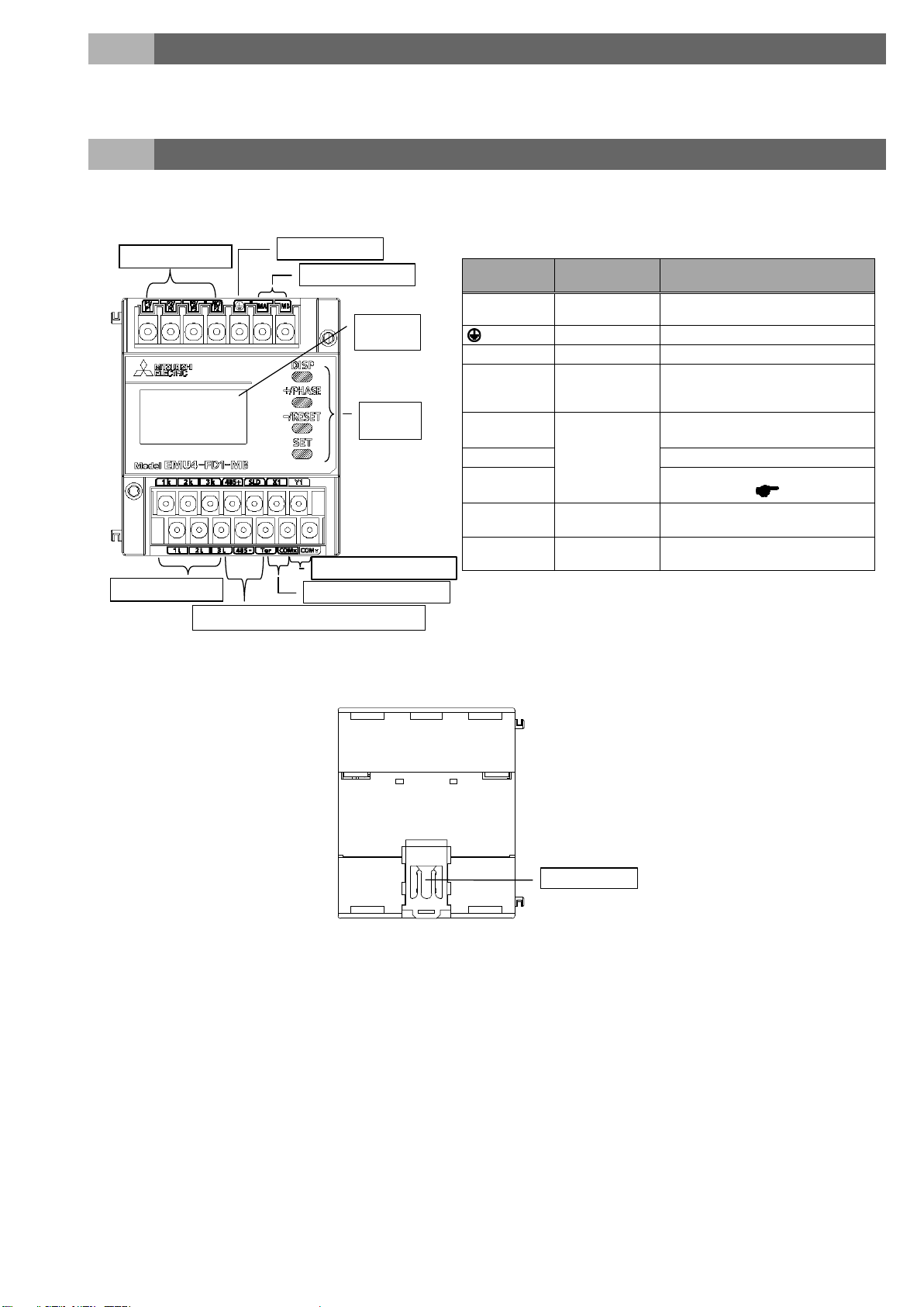
Contact/ pulse input terminals
Contact/ pulse output terminals
Frame GND terminal
Power supply termin als
Voltage input terminals
LCD
display
Operation
button
Communication terminal s
(MODBUS® RTU)
Current input termi nals
IEC
rail fixture
Terminal
symbols
Function
Description
P1/P1, P2/P0,
P3/P3, NC/P2
Input voltage
Connect the voltage input wire of the
measuring circuit.
Frame GND (FG)
Connect to ground. (D-type ground)
MA, MB
Auxiliary power
Connect the auxiliary power supply.
1k, 1L, 2k, 2L,
Input current
Connect the secondary output of the
the measurement circuit’s current wire.
485+, 485-
MODBUS®
Connect the communication wire
(MODBUS® RTU).
SLD
Connect to ground. (D-type ground)
Ter
Connect with “485-“ terminals (the unit
at end of the link) page 13
X1, COMX
Pulse input/
contact input
Connect pulse input/contact input
wires.
Y1, COMY
Pulse output/
contact output
Connect pulse output/contact output
wires.
Sign and function of the terminal block
‧ It is prohibited to reprint or copy all contents of this document in any form without our permission.
‧ The contents of this document will be updated to follow revisions to software and hardware, however under unavoidable
circumstances it may not be synchronized.
3. Name and function of each part
・ Name of each part
・ Back view
3k, 3L
current transformer (CT) connected to
communication
(5/71)
Page 7
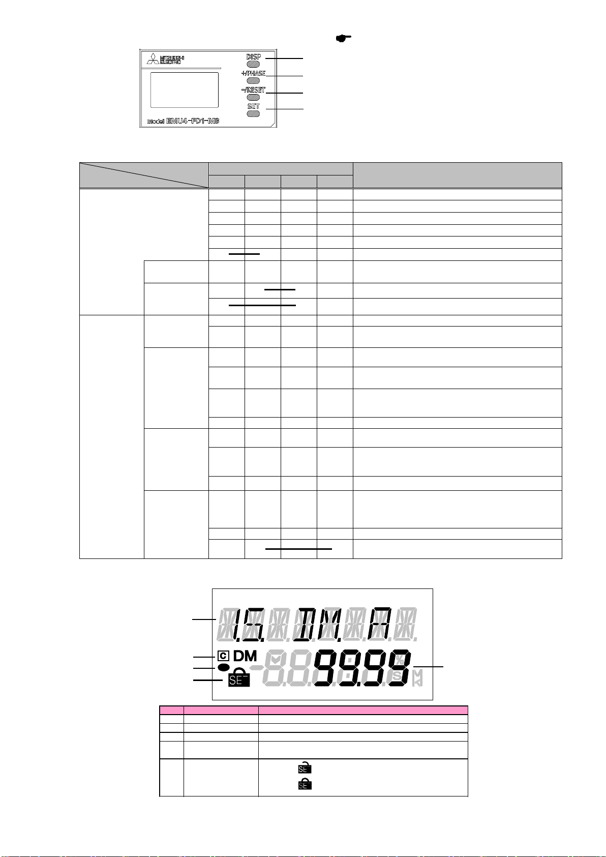
・ Function of operation buttons
Mode
Name of Button
SET
-/RESET
+/PHASE
DISP
Change measured items
Change phase
Change harmonic order (at harmonic display)
Clear alarm (at alarm keeping)
Transition to confirmation mode
Transition to setting mode
display
Integrated
display
Enter setting menu
(Move at fast speed when pressing more than 1sec)
Change of setting items (forward)
Transition to setting menu number (at final setting item)
Moving up or down of setting value
(Move at fast speed when pressing more than 1sec)
Change setting items (backward)
item)
Go back to setting menu
Change setting items (forward)
Transition to setting menu number (at final setting item)
Change setting items (backward)
item)
At "END" display, memorize changed setting and transition
to operating mode
Moving up or down of setting value
Reset setting values to factory default (only effective at
CANCEL display)
No.
Indicator
Description
1
Measured value
Display measured value digitally.
2
Measured item
Display measured item displayed on indicator 1.
3
Communication
Light when connecting communication unit.
4
Energy
Measurement
Light when measuring electric energy
5
Setting
Indicator lights on setting mode.
Indicator lights on confirmation mode.
2
1
3
4
5
SET button
Control buttons have many functions as below. (How to change mode page 15.)
DISP button
+/PHASE button
-/RESET button
Meaning of symbol: ○ (Press), □ (Press more than 1 sec), ◎ (Press more than 2 sec), ― (Press both at the same time)
Setting mode
Confirmation
Operating
Mode
/
mode
Operation
Contact
value
Menu
display
Setting mode
/
Setting
display
Confirmation
mode /
Setting
display
○
○
○
◎
◎
◎ ◎
◎
◎ ◎
◎ ◎
○
○
○
□
○
○
□
○
(□)
○
(□)
○
(□)
○
(□)
Function
Clear contact latch
Transition to preset display
Transition to reset display of all data
Moving up or down of menu number
Transition to setting menu number (at beginning setting
Transition to setting menu number (at beginning setting
Transition to setting menu
Confirmation
display of
setting
reflection
○
○ ○
◎ ◎
to operating mode
At "CANCEL" display, annul changed setting and transition
・ Functions of LCD
(6/71)
Page 8
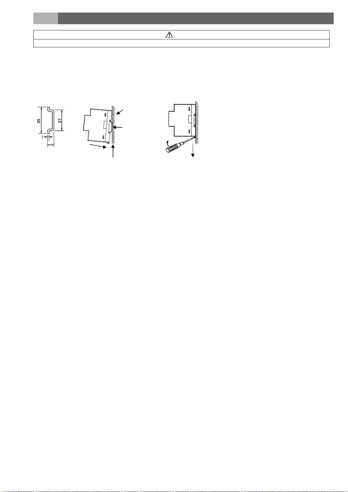
4. Attaching and removing the unit
Caution
Any person who is involved in the installation and the wiring of this unit should be fully competent to do this work.
(2) Catch
IEC rail
(4) Push the IEC rail
fixture upward.
(3) Push in
(1) Hold the unit and pull IEC rail
fixture downward.
(2) Pull the unit
(1) Pull IEC rail fixture downward.
More than 7.3
There are two installation methods, surface mounting and panel mounting
・ Surface mounting
(1) How to attach to the IEC rail
Applicable IEC rail Attaching Removing
*1: When showing the display part by cutting the panel face in mounting the IEC rail, cut the panel at where it is more than 50mm away
from the fulcrum of the open/close of the door.
(7/71)
Page 9
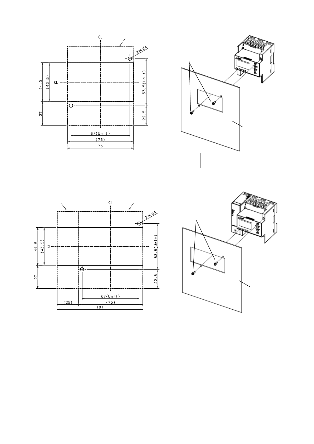
・ Plate mounting
Dimensions of hole panel(76×44.5)
Attaching
Dimensions of hole panel(101×44.5
Attaching
Plate
Attach the plate by using 2 screws.
Tight
Mounting screws
Outline of the measuring unit
Outline of the option unit
Attach the plate by using 2 screws.
Tight
Mounting screws
Plate
cross recessed head screw with captive washer
M3×10 2pcs
Outline of the measuring unit
*Panel cut dimensions are made larger than the product considering
*Panel cut dimensions are made larger than the product considering
(1) Screw mounting (Measuring unit)
tolerance in panel cut.
If you want to prevent dust and other intrusion the gap of panel cut,
cut the panel according to the product to be mounted.
(2) Screw mounting (Measuring unit + optional unit)
)
ening torque: 0.63N・m
Recommended
screws
and flat washer
ening torque: 0.63N・m
tolerance in panel cut.
If you want to prevent dust and other intrusion the gap of panel cut,
cut the panel according to the product to be mounted.
(8/71)
Page 10
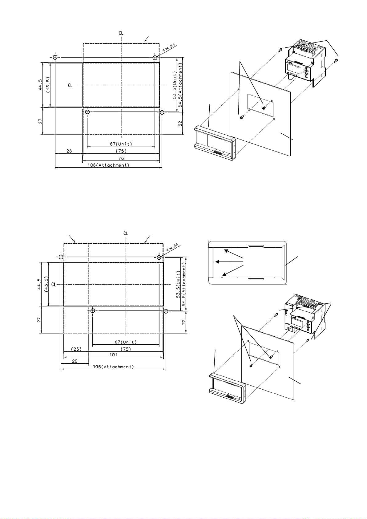
(3) Screw mounting (When using the measuring unit and the attachment for panel mounting)
Dimensions of hole panel(76×44.5
Attaching
Dimensions of hole panel (101×44.5)
Attaching
Tightening torque: 0.63N・m
Plate
Attachment for panel
mounting
Attach the plate by using 2 screws, then install the
attachment on the plate.
Tight
Mounting screws
Screws for panel
Plate
Attachment for panel
mounting
Mounting screws
Screws for panel
*Please screw up the panel mounting attachment where there are high
Outline of the measuring unit
*Please screw up the panel mounting attachment where there are high
Outline of the measuring unit
Outline of the option unit
*Panel cut dimensions are made larger than the product considering
cut the panel according to the product to be mounted.
*Panel cut dimensions are made larger than the product considering
)
tolerance in panel cut.
If you want to prevent dust and other intrusion the gap of panel cut,
cut the panel according to the product to be mounted.
mounting
ening torque: 0.63N・m
levels of vibration.
*The screws (mounting screws and screws for panel mounting
attachment) are supplied with panel mounting attachment.
attachment
(4) Screw mounting (Measuring unit + optional unit, when using the attachment for panel mounting)
tolerance in panel cut.
If you want to prevent dust and other intrusion the gap of panel cut,
Attach the plate by using 2 screws, then install the attachment on the
plate (Use the attachment to cut the three points as below).
Attachment for
panel mounting
Cut off
mounting
attachment
levels of vibration.
*The screws (mounting screws and screws for panel mounting
attachment) are supplied with panel mounting attachment.
(9/71)
Page 11
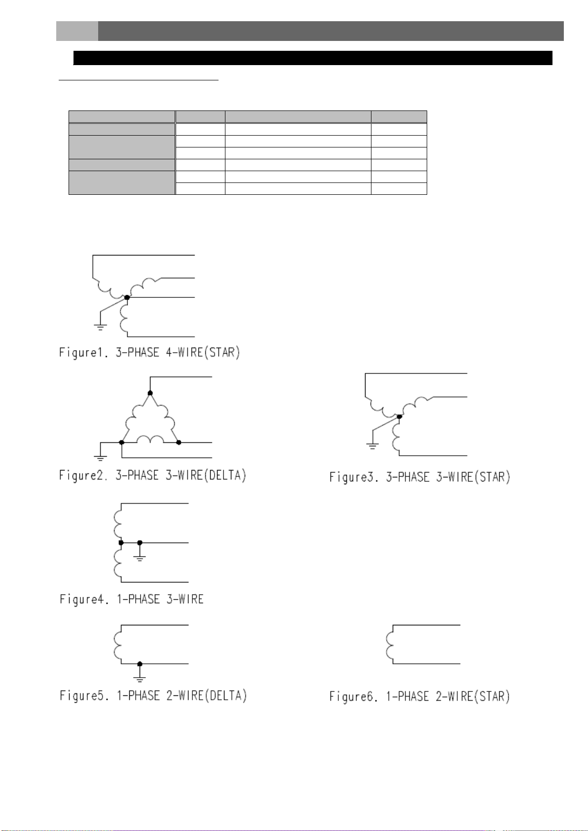
5. Procedure for wiring
Wiring for EMU4-FD1-MB
Rating voltage for every phase wire system
Phase wire type
Type
Rating voltage
Figure
3-phase 4-wire type
STAR
max AC277V(L-N)/480V(L-L)
Figure 1
DELTA
max AC220V(L-L)
Figure 2
STAR
max AC440V(L-L)
Figure 3
1-phase 3-wire type
―
max AC110V(L-N)/220V(L-L)
Figure 4
1-phase 2-wire type
(Note)
DELTA
max AC220V(L-L)
Figure 5
STAR
max AC440V(L-L)
Figure 6
maximum rating is “AC440V”.
3-phase 3-wire type
Note. In case of a circuit which is wired from the delta connection of a 3-phase 3-wire type, a circuit of a transformer of a
1-phase 2-wire type or a 1-phase 3-wire type, the maximum rating is “AC220V”.
In case of a circuit which is wired from a 3-phase 4-wire type or the star connection of a 3-phase 3-wire type, the
(10/71)
Page 12

* Fuse is required to conform to UL.
grounding the secondary side of VT and CT.
*2,3,4(refer to next page)
*1,4(refer to next page)
*2,3,4(refer to next page)
*1,4(refer to next page)
*1,4(refer to next page)
(See*3)
(See*4)
(See*4)
(See*3)
(See*2)
k
l
l
k
l
l
k
l
l
k
l
l
k
l
l
k
l
l
k
l
l
k
l
l
k
l
l
k
l
l
k
l
l
Note 1: For low voltage circuits, do not connect to
(11/71)
Page 13
Applicable wire
Tightening
torque
Recommended crimp-type terminal
Auxiliary power, voltage
stranded wi re: AW G26-14(0.13~2.0mm2)
single wire : AW G26-14(φ0.41~1.62mm)
0.8~1.0N・m
For M3.5 screw of external diameter below 5.6mm
Current input terminals
stranded wi re: AW G18-14(0.82~2.0mm2) *5
single wire : AW G18-14(φ1.03~1.62mm)
0.5~0.6N・m
For M3 screw of external diameter below 5.6mm
Input and output terminals
stranded wire : AWG22-14(0.33~2.0mm2)
single wire : AW G22-14(φ0.65~1.62mm)
0.5~0.6N・m
For M3 screw of external diameter below 5.6mm
*1 For low voltage circuits, do not connect to grounding the secondary side of VT and CT.
Condition
distance
Power line 600V or less
300mm or longer
Other power line
600mm or longer
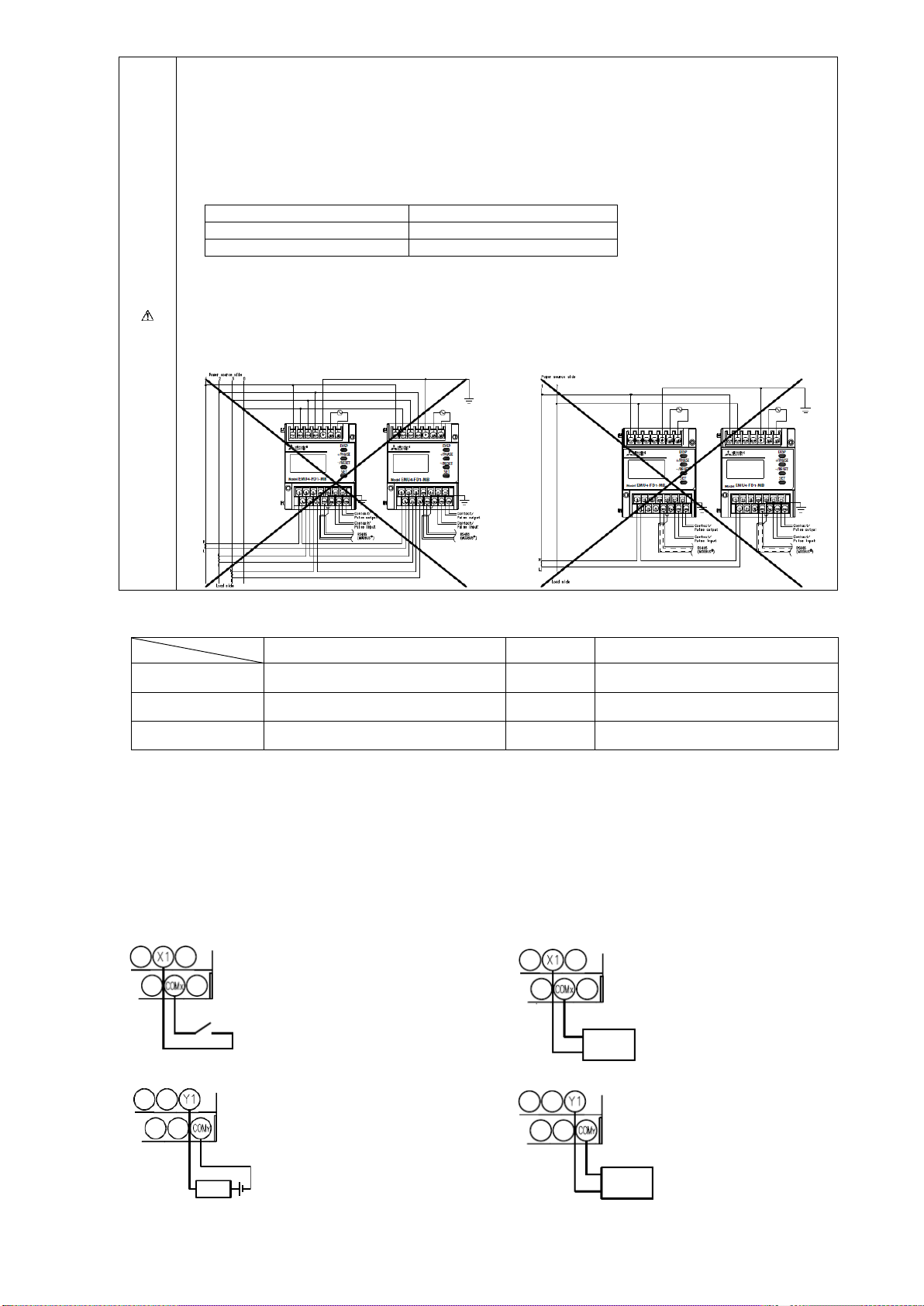
No-voltage a-contact
Use an appropriate type for
5V DC 7mA switching.
No-voltage a-contact
Use an appropriate type for
5V DC 7mA switching.
No-voltage a-contact
35V DC
24V AC 75mA (power factor : 1)
No-voltage a-contact
35V DC
24V AC 7 5m A (power factor : 1)
Transmitter
Counter
Relay
Caution
*2 When this unit is used at a high voltage circuit, the terminal P0 (P2) must be connected to ground.
*3 When grounding a CT line, please make the L side of the CT a common line and connect 1L,2L,3L terminal
for the unit side by the shortest course.
*4 When connecting the L side of the CT by a common line, please connect 1L, 2L, 3L terminal for the unit
side by the shortest course.
・ For protection against noise, transmission lines and input/output lines shall not be placed close to or bound
together with the power lines and high-voltage lines. Keep distance as below between them. (except for
the terminal block)
・ For the actual usage, connect the FG terminal to ground. (D-type ground: Type 3) Connect it directly to the
ground terminal.
This is being bonded to the conductive part of the product for safety reasons and being connected to the
terminal which is connected the outside protection grounding system.
・ Do not connect to FG terminal during the insulation resistance test and pressure test.
・ Do not connect together more than one EMU4-FD1-MB on the secondary side of a current transformer.
・ Do not connect together other units and EMU4-FD1-MB on the secondary side of a current transformer.
・ Use appropriate crimp-type terminal. Appropriate crimp-type terminal is as below.
・ Use electric wires as below, and tighten the terminal screws by the torque as below.
input terminals
*5: If the diameter of the wire is small, the conductor resistance of the wire will be high and the consumption VA of the wire will increase.
・ Maximum voltage of the circuit connected to this unit directly is 277 / 480V. For the circuit over this voltage, use the transformer.
Decide wire diameter and wire length so that it does not exceed the rated burden of CT to be connected.
Using the transformer, primary voltage is configurable up to 6600V.
(Primary voltage of VT can be set up to 6600V, and secondary voltage of VT can be set up to220V as optional setting.)
®
・ For MODBUS
NET transmission from MODBUS
RTU communication wiring, recommended to have the extra length wires about 200mm (When extended to B /
®
communication, use of MODBUS
・ When screwing the terminals at both ends of the terminal block, be careful not to touch the projection of the terminal block cover.
・ In case using external input and/or external output, refer to the following.
External input:For the case of contact input External input: For the case of pulse input
External output:For the case of contact output External output: For the case of pulse output
75mA or,
®
RTU communication wiring is possible).
75mA or,
(12/71)
Page 14
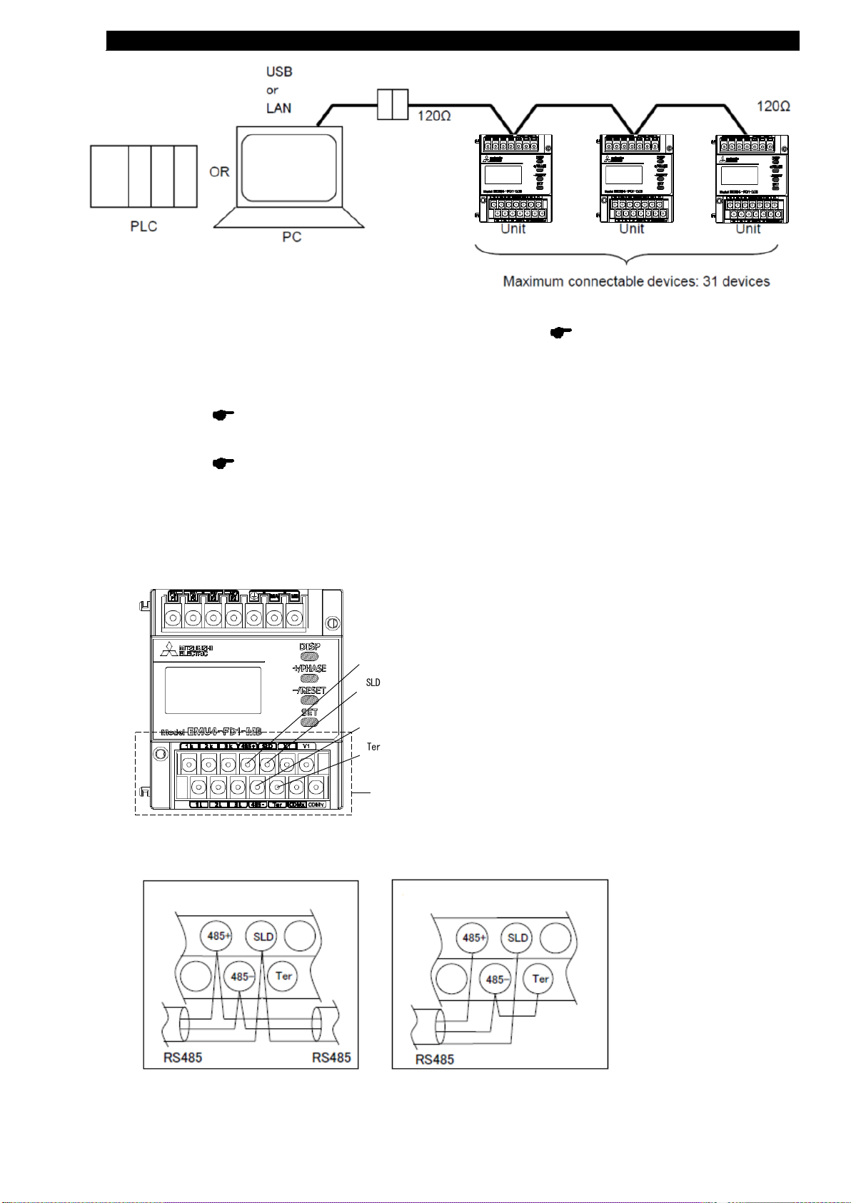
System configuration example of MODBUS®RTU communication
Installation in the middle of the
Installation at the end of the
MODBUS®RTU
・Connection of MODBUS®RTU communication terminals:
1. Use the twisted shielded pair cable for transmission lines.(Recommended cable page 66.)
2. About the terminal resistance of the MODBUS
®
RTU transmission line
・Please get terminal resistance of 120 Ω to the apparatus of transmission line both ends.
(Termination resistances of 120Ω can be used by short-circuiting “485-” and “Ter” terminals.)
・When you are connected to the PLC on transmission line one, please get terminal resistance of 110 Ω in the PLC side.
(Please refer to Page14, "・Wiring for MODBUS
®
UNIT(QJ71MB91) and EMU4-FD1-MB "
for the details.)
・When you are connected to the GOT on transmission line one, please get terminal resistance of 110 Ω in the GOT side.
(Please refer to Page14, "・Wiring for GOT(GOT1000) and EMU4-FD1-MB " for the details.)
3. Connect to ground by using thick wires to decrease impedance.
4. MODBUS
®
RTU transmission lines shall not be placed close to or bound together with the high-voltage lines.
5. Ground the “SLD” terminal at one end.
・wiring terminal
EMU4-FD1-MB
485+
SLD
485-
Ter
・Procedure for wiring
transmission rout
Connect to
Terminal
transmission rout
(13/71)
Page 15
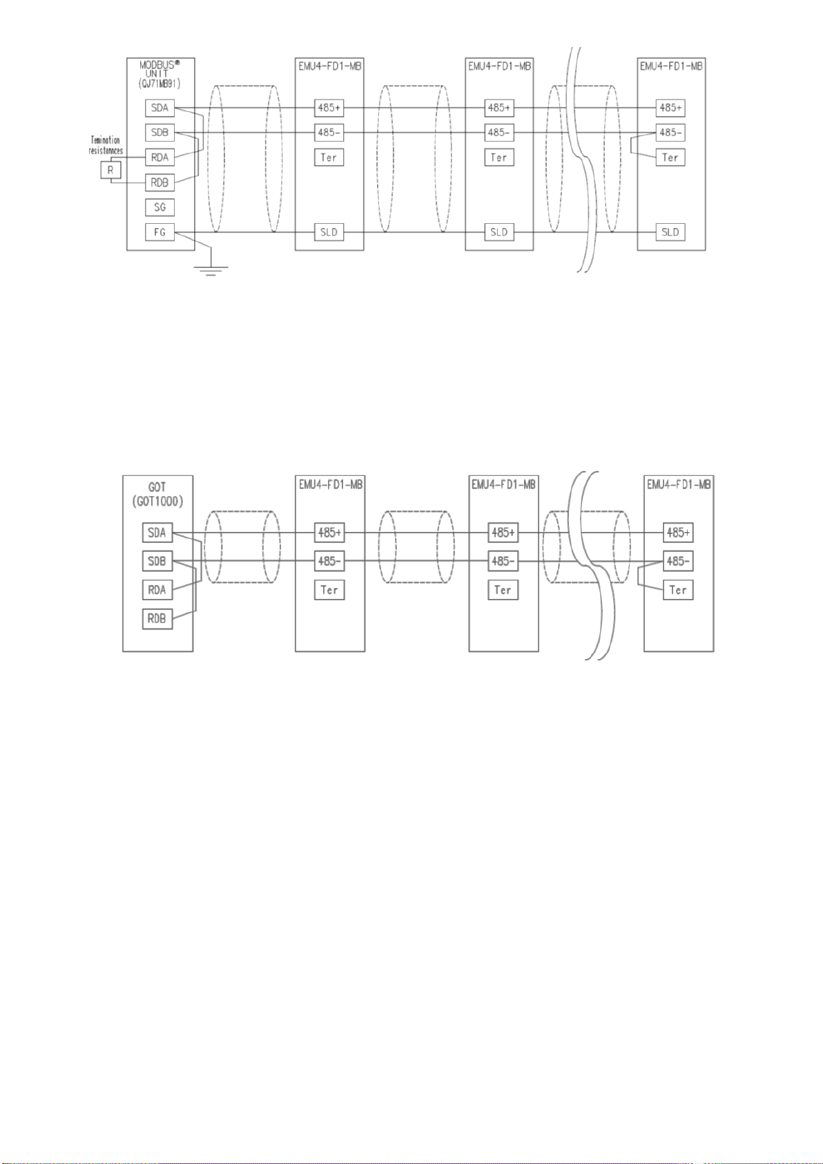
・Wiring for MODBUS®UNIT(QJ71MB91) and EMU4-FD1-MB
Note) The terminal resistance of the MODBUS
®
unit (QJ71MB91) side, please connect "110Ω 1/2W".
For details, please refer to "Mitsubishi frequent use sequencer MELSEC-Q Series (QJ71MB91)
MODBUS
®
interface unit (details).“
・Wiring for GOT(GOT1000) and EMU4-FD1-MB
Note) Please set the terminal resistance of the GOT(GOT1000) "110 Ω".
Please of the setting method refer to " GOT1000 Series Connection Manual (Microcomputer, MODBUS
Products, Peripherals) for GT Works3".
(14/71)
Page 16
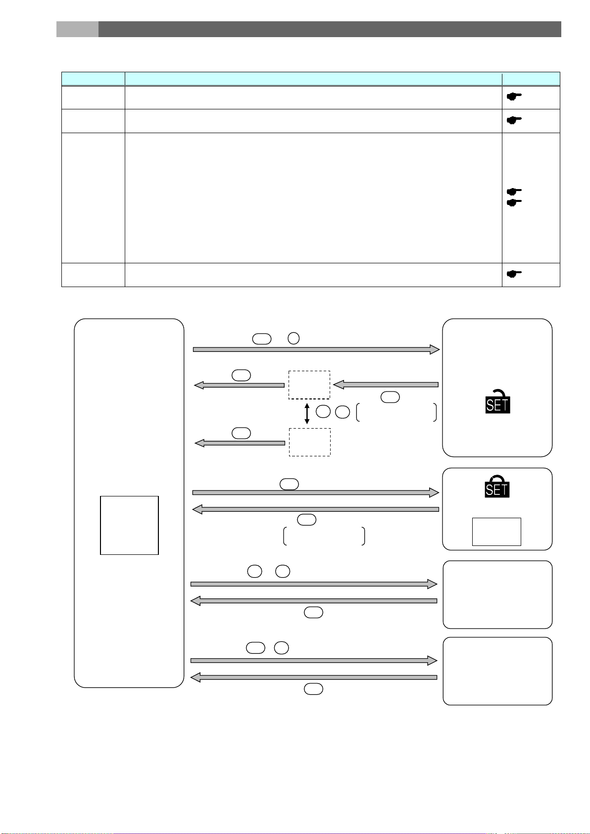
6. Operating mode
This unit has the operating modes. Switch these modes according to the purposes. The operating mode is displayed
Mode
Function
Reference
Operating
mode
Display measured value digitally. It can display the condition of contact input and present time (*1)
other than the present value of the measured values.
Setting mode
Set basic setting for phase wire method, primary voltage, primary current and alarm monitoring for
alarm output elements.
Confirmation
Mode to confirm the setting value for each setting item.
Display useful to discriminate for incorrect wiring such as phase angle display of voltage,
Send back fixed numerical data without measurement (voltage and current) input.
Reset mode /
Preset mode
Reset: Integrated values (electric energy, operating time, etc.) can be zeroed.
Preset: Preset of electric energy and reactive energy.
Preset mode
Operating mode
Present value
display
+
Press both at the s ame time for 2 sec
SET
-
Press for 2 s ec
When selecting "End"
on the menu
SET
SET
CANCEL
display
Cancel change of
setting value
SET
End
display
Fix change of s etting value
When selecting
"End" on the menu
SET
SET
+
-
Setting mode
immediately after the auxiliary power loading.
page 49
page 16
mode
(Test mode)
(The Setting cannot be changed in this mode, so it can be prevented setting change by human
error.)
In addition, this unit
has the test function that can be used for such as set up of an equipment.
・ Discrimination support display for incorrect wiring:
current.
・ Pulse, Alarm test:
Switch pulse output contact and alarm contact without measurement (voltage and current)
input.
・ Communication test:
*1: Only when connecting logging unit.
page 30
page 34
page 56
(15/71)
Page 17
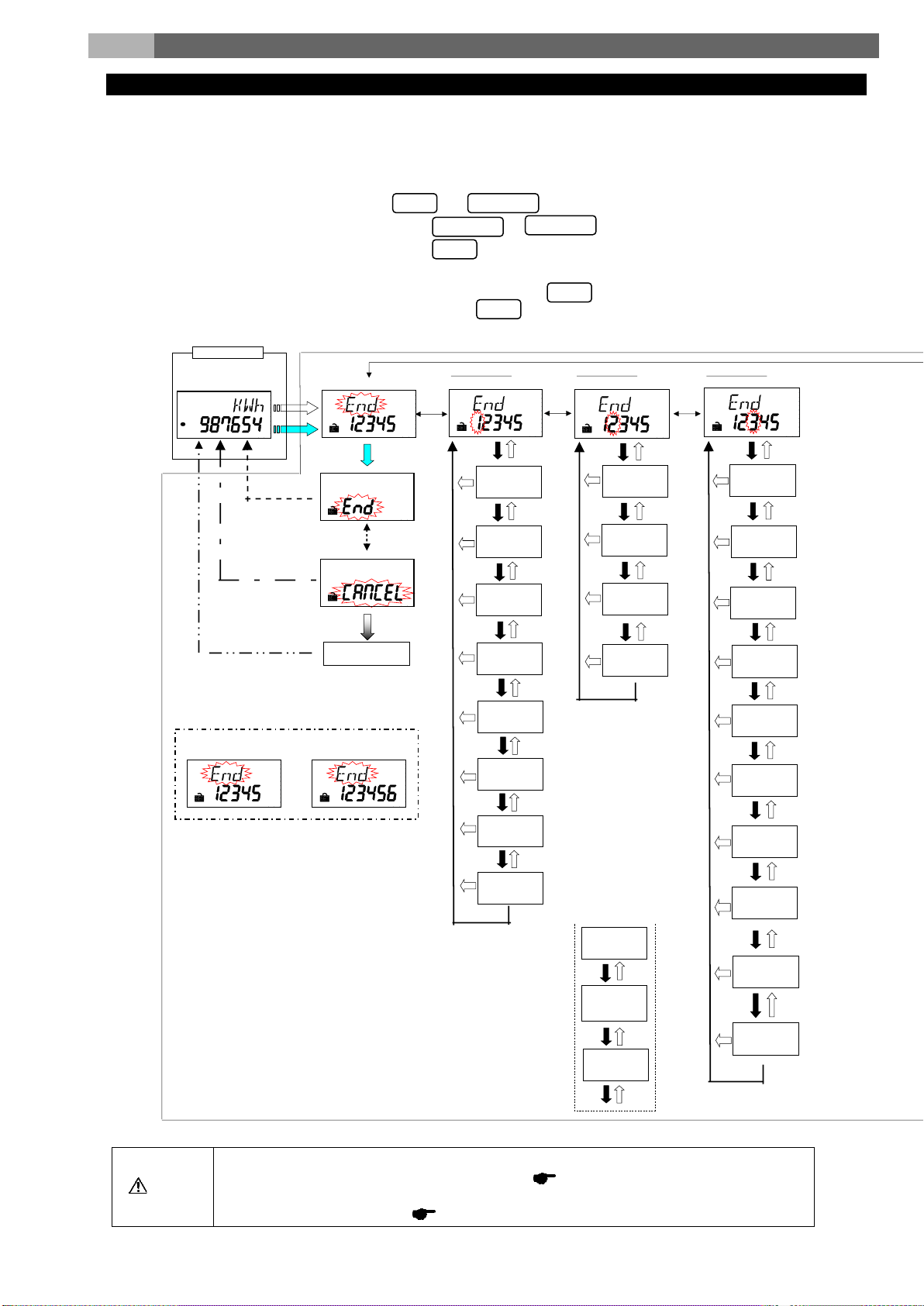
7. Setting method
Procedures for setting
Setting menu 5 related to the logging Unit is shifted to Setting mode from Operating mode, and
Please check them beforehand.
page 31
Phase wire system
Factory default
Primary v oltage
(use or non-use of
VT)
Primary v oltage
(With VT o r Direct)
Primary current
Secondaryc urrent
Curre nt demand
ti me
Model Name
MODBUS®RTU
addre ss
MODBUS®RTU
baud ra te
MODBUS®RTU
pari ty
MODBUS®RTU
sto p bit
Contac t / pulse
input
Reset method
of c ontact inp ut
Contac t / pulse
output
"End" display
Unit amount o f
pulse output
※3
Equival ent CO2
indication
※4
CO2 conversion
fact or
※5
Harmonic current
indication
Harmonic voltage
indication
Operating time
indication
Counting method
of operating time
※2
Primary spec ial
voltage
Secondary special
voltage
Primary v oltage
(VT voltage)
※1
※2
Opera ting mode
Meas urement dis play
Fix of setting
value cha nge
Canc el o f se tting
value cha nge
"CANCEL" di spla y
Transition automatically
Example of s ett ing
mode dis play
Example of confirmation
mode dis play
End of setting menu
Setting menu 1
Basic setting
Setting menu 2
Comm unication s etting
Setting menu 3
Input/output s etting
For the special voltage (SP)
(Not available for 1P3W)
※11
- / RESET
SET
+ / PHASE
- / RESET
SET
SET
SET
Set items such as phase wire system, primary voltage, and primary current in the setting mode to measure and monitor.
Under normal use, it shall be sufficient to set the setting menu 1 (Basic setting) only.
For details, refer to after the following page.
<How to set>
(1) Go into the setting mode by pressing both and at the same time for 2 sec.
(2) Select the setting menu number by pressing or .
(3) Determine the setting menu number by pressing .
(4) Set each setting item.
(5) After all setting are done, select “End” on the setting menu and press .
(6) When prompted for End display, select “End” and press .
・
Caution
Please go in a procedure to set only Setting menu 5.
・If you change setting, related setting items and measured data are initialized.
page
(16/71)
28
Page 18
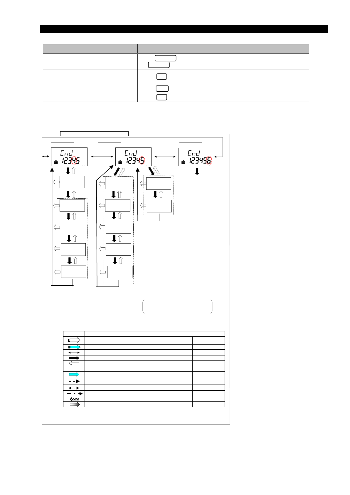
Procedures for setting
Function
Operation
Supplement
Press
or .
After setting value is confirmed, transition
to next item.
Go back the previous setting item
Press .
Go back to setting menu during setting
Press for one second.
Reset setting values to factory default.
"DISP"
+ "-"
Press once
Canc el cha nge of setting v alue.
"SET"
Press once
Skip o ther ite ms during s etting.
"SET"
Press for 1 sec
Memorize changed setting and transition to operating
mode.
"SET"
Press once
Select "CANCEL".
"+" or "-"
Press once
No dis play
Sele ct s ett ing v alue.
"+" or "-"
Press several times
Trans iti on to "End" dis play.
"SET"
Press once
Enter each setting display or transition to next item.
"SET"
Press once
Go bac k to previ ous set ting di splay.
"DISP"
Press once
Transition from operating mode to confirmation mode
"SET"
Press for 2 sec
Sele ct menu number or "E nd".
"+" or "-"
Press several times
Sy mbol
Behavior
Operation of control button
Transition from operating mode to setting mode.
"SET" + "-"
Pres s both at t he
same time for 2 sec
Use of upper /
lower limit alarm
Upper / lower limit
alarm el eme nt
Upper / lower limit
alarm value
Alarm delay time
Alarm rese t
method
Logging module
ID
Logging data clear
conf irmation
Test mode
※6
※10
Setting menu 4
Alarm s etting
Setting menu 5
MODB US®TCP setti ng / Logging setting
Setting menu 6
Test mode
Setting mode or confirmation mode
※1: On confirmation mode, transition to operating mode.
※2: Transition only when selecting "SP" for "Primary v oltage
(VT or direct voltage)" on Setting menu 1.
(For 3P4 W, only spe cia l volt age i s ava ilable when usi ng VT.)
※3: Tra nsit ion only whe n s electi ng "CO. P." for "Cont act /puls e
input".
※4: Trans iti on o nly whe n s elec ti ng "PLS" for "Co ntac t/pulse
output ".
※5: Transi tio n only whe n se lect ing "on" f or "Equiva lent CO2
indic ati on".
※6: Trans iti on only when s elec ting "o n" for "Use of upper/lo wer
li mit ala rm".
※7: Trans iti on only when c onnec ting MODBUS®T CP module.
※8: Trans iti on only when s elec ting "o n" for MODBUS®TC P
Default G/W existence".
※9: Transi tio n only whe n co nnect ing loggi ng module.
※10: Not dis play ed o n se tti ng mode.
※11: The followi ng data is not c lear ed.
Elec tri c ene rgy (consumptio n, r egene rat ion) ,
Reactive energy,
Equiv alent C O2 (hi de),
Operation time (hide)
Whe n sele ct ing "CO. P."f or "Count ing metho d of ope rat ing
※7
US®TCP
※9
ault G/W
ault G/W
Reset
※8
DISP
+ / PHASE
- / RESET
SET
SET
・ Basic operations in setting
Choose setting value
confirm setting value
Press .
Press for more than one second to
fast-forward
Setting value of the last item before return
is effective.
(17/71)
Page 19
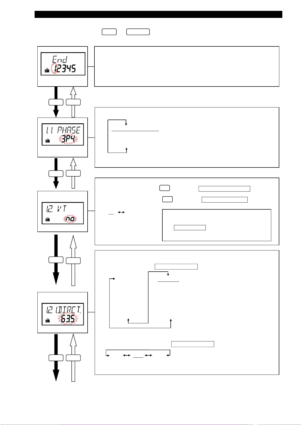
Setting menu 1: Phase wire system, primary voltage, primary current, demand time, etc.
In this menu, set phase wire system, primary voltage, primary current, demand time, etc.
- / RESET
SET
In operating mode, press both and at the same time for more than two seconds to transition to setting
mode and enable the following operations.
Setting menu
Choose the setting menu 1.
(As shown in the left figure)
SET
DISP
(1) Phase wire system
SET
DISP
(2) Primary voltage
(Use or non-use of VT)
SET
DISP
Set according to the phase wire system for the measured circuit.
3P4: Three-phase 4-wire
1P2: Single-phase 2-wire
1P3: Single-phase 3-wire
3P3: Three-phase 3-wire
Supplement: The underlined values are the defaults. (The same shall apply hereinafter.)
If you measure directly (i.e. without VT):
→Choose “no” and press to transition to (3) Primary voltage (Direct).
SET
If you measure with VT:
→Choose “yES” and press to transition to (4) Primary voltage (VT).
no
Supplement:
“VT” means Voltage Transformer.
yES
SET
<In case you choose “1P3” in (1) Phase wire system>
You can use direct measurement only.
Setting of primary voltage is skipped and setting is started
from (7) Primary current
Rated voltage between 1- and 2-phase and 2- and 3-phase is
110V, and that between 1- and 3-phase is 220V.
Set the direct voltage according to voltage of the measured circuit
・ In case you choose “3P4”in (1) Phase wire system
(3) Primary voltage
(Direct)
63.5V/110V
100V/173V
105V/182V
110V/190V
115V/199V
120V/208V
127V/220V
200V/346V
220V/380V
230V/400V
240V/415V
242V/420V
250V/430V
254V/440V
265V/460V
277V/480V
・ In case you choose “3P3” or “1P2”in (1) Phase wire system
SET
DISP
110V 220V 440V
(18/71)
Page 20
Setting menu 1: Phase wire system, primary voltage, primary current, demand time, etc.
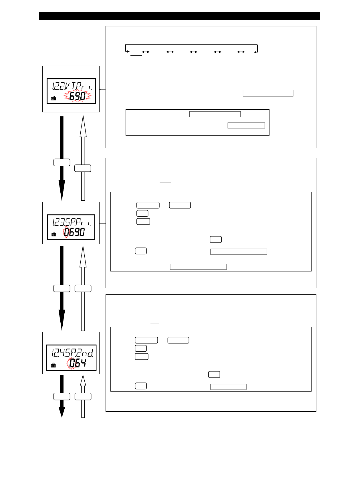
(4) Primary voltage
Set the primary voltage of combined VT
690V 1100V 2200V 3300V 6600V SP
(with VT)
SET
(5) Special primary
voltage
DISP
Caution:
If there is no values above you want to set to, choose “SP” to enable the special primary
voltage and the special secondary voltage.
In case you choose “3P4” (three-phase 4-wire system) in (1) Phase wire system, the
special voltage is only available.
If you choose “SP”, transition to “ (5) Special primary voltage”.
If you choose the value except for “SP”, transition to “(7) Primary current ”.
(In this case, secondary voltage is fixed to 110V.)
Set the special primary voltage of combined VT.
・ Setting range: 1V to 6600V
Default value is 690V
Setting of special primary voltage
・ Press or to choose the value at flashing digit.
・ Press for the setting digit (flashing digit) to shift to lower.
・ Press for the setting digit (flashing digit) to shift to upper.
・ You can set the upper three digit of the value to the range of 1V to 6600V.
・ Press at the lowest digit to transition to “(6) Special secondary voltage”.
SET
DISP
Caution: In case you set the value except for between 1V and 6600V, indicate the error (E005).
When indicating the error, press to check the setting values and set the new
value again.
SET
The values set the upper fourth digit and lowers to are rounded down. After setting value flashes
three times, transition to “ (6) Special secondary voltage”.
- / RESET + / PHASE
SET
(6) Special secondary
SET DISP
voltage
SET DISP
Set the special secondary voltage of combined VT.
・ Setting range: 1V to 220V
Default value is 110V (for three phase 3-wire system and single-phase 2-wire
system), or 64V (for three-phase 4-wire system).
Setting of special secondary voltage
・ Press or to choose the value at flashing digit.
・ Press for the setting digit (flashing digit) to shift to lower.
・ Press for the setting digit (flashing digit) to shift to upper.
・ You can set the value to the range of 1V to 220V.
・ Press at the lowest digit to transition to “(7) Primary current”.
SET
DISP
Caution: In case you set the value except for between 1V and 220V, indicate the error (E005).
When indicating the error, press to check the setting values and set the new
value again.
SET
- / RESET + / PHASE
SET
(19/71)
Page 21
Setting menu 1: Phase wire system, primary voltage, primary current, demand time, etc.
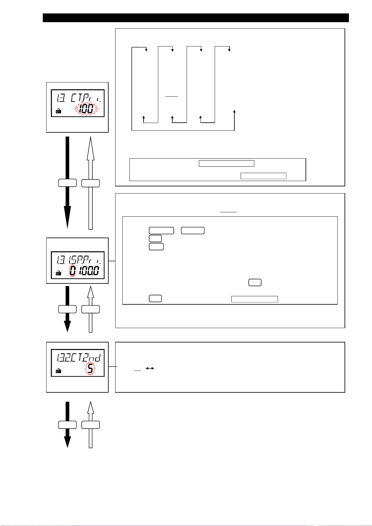
(7) Primary current
Set the primary current of combined CT.
1A
5A
6A
7.5A
8A
10A
12A
15A
20A
25A
30A
40A
50A
60A
75A
80A
100A
120A
150A
200A
250A
300A
400A
500A
600A
750A
800A
1000A
1200A
1250A
1500A
1600A
2000A
2500A
3000A
4000A
5000A
6000A
SP
Supplement:
“CT” means Current Transformer.
Supplement: If there is no values above you want to set to, choose “SP” to
enable the special primary current.
If you choose “SP”, transition to “(8) Special primary current”.
If you choose the value except for “SP”, transition to “(9) Secondary current”.
SET
DISP
Set the special primary current of combined CT.
・ Setting range: 1A to 6000A (Default: 100.0A)
Setting of special primary current
・ Press or to choose the value at flashing digit.
(8) Special primary
current
・ Press for the setting digit (flashing digit) to shift to lower.
・ Press for the setting digit (flashing digit) to shift to upper.
・ You can set the value in the range from 1A to 6000A.
・ Press at the lowest digit to transition to “(9) Secondary Current”.
SET
DISP
(9) Secondary current
Set the secondary current of combined CT.
- / RESET + / PHASE
SET
DISP
If the value is less than 10A, you can set upper two digits of it.
If the value is 10A or more, you can set upper three digits of it.
Caution: In case you set the value except for the range from 1A and 6000A, indicate the error
(E005). When indicating the error, press to check the setting values and set
the new value again.
SET
SET
5A 1A
SET DISP
(20/71)
Page 22
Setting menu 1: Phase wire system, primary voltage, primary current, demand time, etc.
(10) Current demand
Set the current demand time.
On setting display, “s” means “second” and “M” means “minute”.
time
SET
(11) Electric power
demand time
SET
(12) Model code
DISP
DISP
0s
10s
20s
Set the electric power demand time.
On setting display, “s” means “second” and “M” means “minute”.
The model code can be confirmed.
(This is only display, and settings cannot be changed.)
30s
0s
10s
20s
30s
40s
50s
1M
2M
40s
50s
1M
2M
3M
4M
5M
6M
3M
4M
5M
6M
7M
8M
9M
10M
7M
8M
9M
10M
11M
12M
13M
14M
11M
12M
13M
14M
15M
20M
25M
30M
15M
20M
25M
30M
SET
Setting menu
DISP
Complete the setting or continue in other menu according to procedures for setting.
For procedures for setting, page 16
(21/71)
Page 23

Setting menu 2: MODBUS
®
RTU communication
- / RESET
SET
In this menu, set address, baud rate, parity and stop bit for MODBUS®RTU communication.
In operating mode, press both and at the same time for more than two seconds to transition to setting
mode and enable the following operations.
Setting menu
Choose the setting menu 2.
(As shown in the left figure)
SET
(1) Address for
MODBUS®RTU
SET
(2) Baud rate for
MODBUS
SET
(3) Parity for
MODBUS
DISP
DISP
®
RTU
DISP
®
RTU
Set the address for MODBUS®RTU
・ Available address: 1 to 255
Set the transmission speed for MODBUS®RTU
2400bps 4800bps 9600bps 19200bps 38400bps
Set the Parity for MODBUS®RTU
EVEn non odd
SET
DISP
(4) Stop bit for
MODBUS
®
RTU
Set the stop bit for MODBUS®RTU
1 2
SET
DISP
Setting menu
Complete the setting or continue in other menu according to procedures for setting.
For procedures for setting, page 16
(22/71)
Page 24

Setting menu 3: Contact / pulse input/output, equivalent CO2, harmonic, operating time, etc.
In this menu, set contact / pulse input/output, equivalent CO2, harmonic, operating time, etc.
- / RESET
SET
SET
DISP
In operating mode, press both and at the same time for more than two seconds to transition to setting
mode and enable the following operations.
Setting menu
Choose the setting menu 3.
(As shown in the left figure)
(1) Contact / pulse
input
SET
(2) Reset method of
contact input
DISP
Set External input signal.
non
PLS. C O . P.
Set the reset method of contact input.
Auto
HoLd
Reset method
(Setting value)
Auto-reset
(Auto)
Self-retention
(HoLd)
For pulse input, choose “PLS.”.
For contact input, choose “CO.P.”.
In case you do not set it, choose “non”.
Summery
When contact input turns OFF (open), contact input state display
also turns OFF (open) automatically.
Once the device detects contact input ON (close), contact input state
display keeps ON (close) until retention clear operation even if
contact input turns OFF (open).
Supplement: In (1) Contact / pulse input , when you choose the value except for “CO.P.”,
SET
DISP
(3) Contact / pulse
Set External output signal.
output
non
SET
DISP
this setting is skipped.
PLS. C O . P.
For pulse output, choose “PLS.”.
For contact output, choose “CO.P.”.
In case you do not set it, choose “non”.
(23/71)
Page 25

Setting menu 3: Contact / pulse input/output, equivalent CO2, harmonic, operating time, etc.
(4) Unit amount of pulse
Set the unit amount per pulse of pulse output.
Selectable unit amount is as follows depending on the full load power:
α: 1 Single-phase, 2-wire
2 Single-phase, 3-wire
√3 Three-phase, 3-wire
3 Three-phase, 4-wire
[kWh/pulse]
1 0.1 0.01 0.001
Default
value
0.001
0.01
0.1
output
SET
DISP
α x (VT primary voltage) x (CT primary current)
Full load power [kW ] =
*1: VT primary voltage in single-phase 3-wire system is regarded as 110V.
*2: Using direct connection, replace VT primary voltage with direct voltage in calculation above.
*3: In three-phase 4-wire system, replace VT primary voltage or direct voltage with phase voltage in
calculation above.
Full load power
[kW]
less than 12
12 or more and less than 120
120 or more and less than 1200
1200 or more and less than 12000 1000 100 10 1 1
12000 or more 10000 1000 100 10 10
1000
Selectable unit amount per pulse
10 1 0.1 0.01
100 10 1 0.1
(5) Equivalent CO2
indication
SET
(6) CO2 conversion
factor
DISP
Supplement: In (3) Contact / pulse output, when you choose the value except for “PLS.”, this setting is
skipped.
Set whether the equivalent CO2 is indicated or not.
oFF
(Do not indicate)
CO
equivalent is the integration of the value obtained by multiplying electric energy and CO2 conversion
2
factor.
・ If you need this indication, choose “on” and press to transition to the setting below.
・ If you do not need this indication, choose “oFF” and press to transition to
(7) Harmonic current indication.
on
(Indicate)
SET
SET
Set the CO2 conversion factor
(Default value: 0.555kg - CO
/ kWh)
2
Setting of CO2 conversion factor
・ Press or to choose the value at flashing digit.
・ Press for the setting digit (flashing digit) to shift to lower.
・ Press for the setting digit (flashing digit) to shift to upper.
・ You can set the value to the range of 0.000 to 0.999 (kg - CO2 / kWh).
・ Press at the lowest digit to transition to (7) Harmonic current indication .
SET
DISP
SET
- / RESET + / PHASE
SET
DISP
(7) Harmonic current
Set whether the harmonic current is indicated or not.
indication
oFF
(Do not indicate)
on
(Indicate)
SET
DISP
(24/71)
Page 26

Setting menu 3: Contact / pulse input/output, equivalent CO2, harmonic, operating time, etc.
(8) Harmonic voltage
indication
SET
DISP
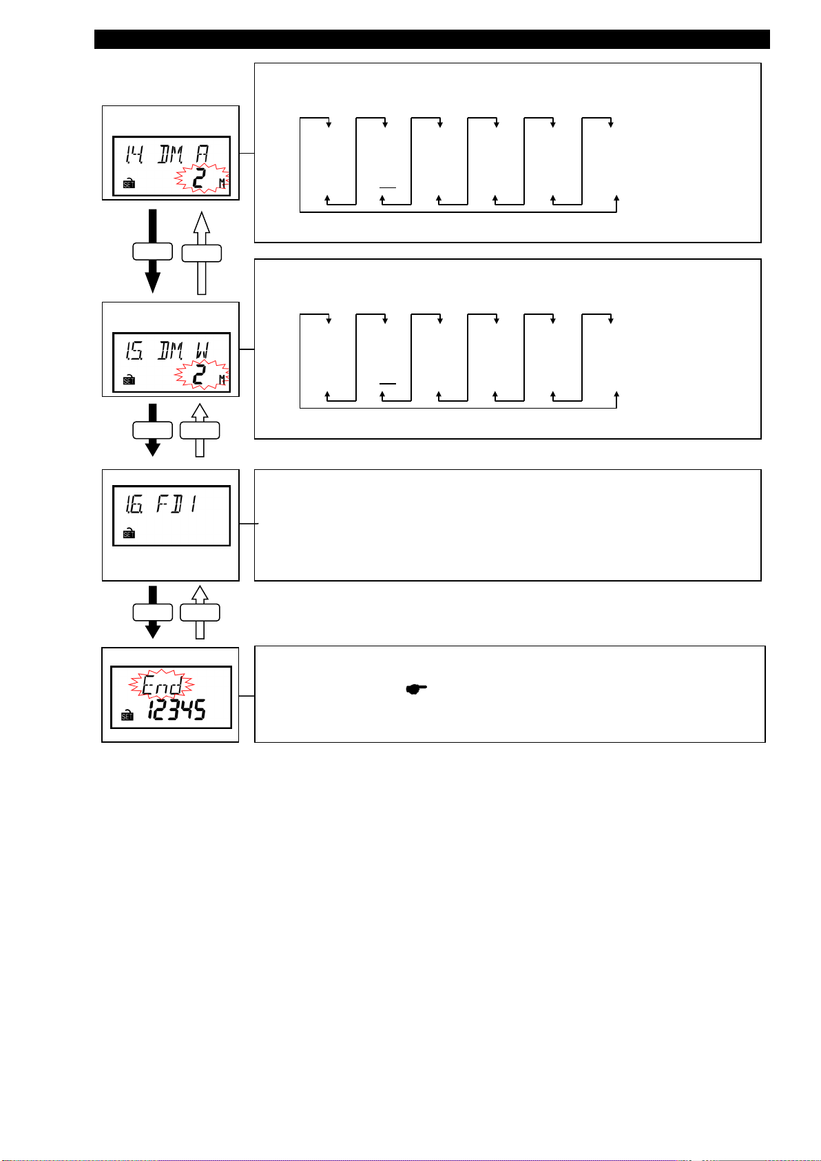
(9) Operating time
indication
SET
DISP
(10) Counting method of
operating time
Set whether the harmonic voltage is indicated or not.
oFF
(Do not indicate)
on
(Indicate)
Set whether the operating time is indicated or not.
(Operating time is integrated while this setting is “oFF”.)
oFF
(Do not indicate)
on
(Indicate)
Set the counting method of operating time.
When “A” is selected, operating time is the time integrated while the current measurement.
When “CO.P.” is selected, operating time is the time integrated while external input is “ON”.
(By current)
SET
DISP
Setting menu
Complete the setting or continue in other menu according to procedures for setting.
For procedures for setting, page 16
A
C O . P.
(By contact input)
(25/71)
Page 27

Setting menu 4: Upper / lower limit alarm setting, alarm delay time, alarm reset, etc.
In this menu, set the upper / lower alarm, alarm delay time, reset method of alarm clear, etc.
- / RESET
SET
In operating mode, press both and at the same time for more than two seconds to transition to setting
mode and enable the following operations.
Setting menu
Choose the setting menu No. 4.
(As shown in the left figure)
SET DISP
(1) Use of upper /
lower limit alarm
SET
DISP
(2) Upper / lower limit
alarm element
Set the use or non-use of upper / lower limit alarm.
oFF
(Do not use alarm)
・ If you do not use alarm, choose “oFF” and press to enter setting menu.
・ If you use alarm, choose “on” and press to transition to the setting below.
on
(Use alarm)
SET
SET
Set the measured element applying upper / lower limit alarm to.
Upper / lower limit alarm of measured value is available by setting this item.
DA upper limit
DA lower limit
DA (N) upper limit
V (L-L) upper limit
V (L-L) lower limit
DW upper limit
DW lower limit
PF upper limit
PF lower limit
PULSE upper limit
V (L-N) upper limit
V (L-N) lower limit
Caution:
1. DA: Current demand, DA(N): N-phase current demand, DW: Electric power demand
2. “DA (N)” and “V (L-N)” are selectable in three-phase 4-wire system
3. “PULSE” is only selectable when you choose “Pulse (PLS.)” on (1) Contact / pulse input of
SET
DISP
Set the alarm value of upper / lower limit alarm element.
Setting range is as follows:
DA upper limit, DA (N) upper limit 0 - 100 (%) of primary current A
(3) Upper / lower limit
alarm value
DA lower limit
V (L-L) upper limit, V (L-N) upper limit
V (L-L) lower limit, V (L-N) lower limit
DW upper limit
DW lower limit
PF upper limit
SET
DISP
PF lower limit
PULSE upper limit
For operation of alarm value setting, refer to next section.
V (L-L) : Line voltage, V (L-N) : Phase voltage
setting menu No.3.
Measured element Setting range Unit
0 - 100 (%) of primary current A
0 - 100 (%) of primary voltage V
0 - 100 (%) of primary voltage V
-100 - 0 - 100 (%) of full load power W
-100 - 0 - 100 (%) of full load power W
-50 - 100 - 50 (%) %
-50 - 100 - 50 (%) %
1 – 999999 (Default value is 100000)
(26/71)
Page 28

Setting menu 4: Upper / lower limit alarm setting, alarm delay time ,alarm reset, etc.
Operations in alarm value setting display are as follows:
Setting of “Upper / lower limit alarm value”
・ Press or to choose the value at flashing digit.
・ Press for the setting digit (flashing digit) to shift to lower.
・ Press for the setting digit (flashing digit) to shift to upper.
・ Setting range is different for each alarm element. (refer to previous section)
・ Press at the lowest digit to transition to (4) Alarm delay time .
+ / PHASE - / RESET
SET
DISP
Caution: In case the value is set to outside-set-value, indicate the error (E005)
When indicating the error, press to check the setting values and set the new
value again.
SET
SET
(4) Alarm delay time
SET
DISP
(5) Alarm reset method
SET DISP
Set the delay time from fulfilling alarm occurring condition.
Set the alarm delay time if you want to avoid the alarm
caused by such as instant overload and noise.
Once setting, the alarm does not occur unless the time of
exceeding the upper / lower limit alarm value is over the specified
delay time.
In setting display, “s” means “second” and “M” means “minute”.
0s
5s
10s
20s
30s
40s
50s
1M
2M
3M
4M
5M
Set the alarm reset method in alarm occurrence.
Alarm reset method
(Setting value)
Auto-reset
(Auto)
Self-retention
(HoLd)
Reset the alarm automatically when alarm occurring condition
is gone.
The alarm is held even after alarm occurring condition is gone.
Button operation is necessary to clear the alarm.
Summery (For details, page 54)
Setting menu
Complete the setting or continue in other menu according to procedures for setting.
For procedures for setting, page 16
(27/71)
Page 29

Setting menu 5: Setting related to logging unit
In this menu, set the logging unit ID or logging data clear.
Setting menu
- / RESET
SET
You should set the setting menu 5 individually.
been completed.
In operating mode, press both and at the same time for more than two seconds to transition to setting
mode and enable the following operations.
Choose the setting menu 5
(As shown in the left figure.)
SET
DISP
(1) Logging unit ID
SET
DISP
(2) Logging data clear
confirmation
SET
DISP
Setting menu
Caution: When the logging module is not connected, the display indicates
“non” (as shown in the right figure) and go back to setting menu
Set the ID number of logging unit.
・Available ID: 1 to 255
Clear the logging data.
no
(Do not clear data)
Complete the setting .
For procedures for setting, page 16
yES
(Clear data)
(“non” indication)
Caution
You should not set it with other setting menu 1 to 4 at the same time.
The setting requests of logging unit and the setting requests of main unit cannot be accepted at
the same time.
Because the setting of logging unit needs for the setting value of main unit which has already
(28/71)
Page 30

Setting menu 5: MODBUS
®
TCP communication
- / RESET
SET
SET
DISP
SET
DISP
SET
DISP
In this menu, IP address, subnet mask, and default gateway for MODBUS®TCP communication.
In operating mode, press both and at the same time for more than two seconds to transition to setting
mode and enable the following operations.
Setting menu
Choose the setting menu 5.
(As shown in the left figure)
SET
(1) IP Address for
MODBUS®TCP
(2)Subnet mask for
MODBUS
DISP
®
TCP
Caution: When the MODBUS®TCP module is not connected, the display
indicates “non” (as shown in the right figure) and go back to setting
menu
Set the local station IP address for MODBUS®TCP by each octet.
0.0.0.0 to 192.168.3.30 to 255.255.255.255
* If invalid IP address is set, error code E005 is appears.
If that happens, press and set again after review the IP address.
[Range of configurable IP address]
1.0.0.0 to 126.255.255.254
128.0.0.0 to 191.255.255.254
192.0.0.0 to 223.255.255.254
The following IP addresses cannot be configured.
・0.0.0.0
・xxx.xxx.xxx.255 (xxx are any values)
SET
Set the subnet mask.
Select the subnet mask from the below table.
(1) 128.0.0.0 (9) 255.128.0.0 (17) 255.255.128.0 (25) 255.255.255.128
(2) 192.0.0.0 (10) 255.192.0.0 (18) 255.255.192.0 (26) 255.255.255.192
(3) 224.0.0.0 (11) 255.224.0.0 (19) 255.255.224.0 (27) 255.255.255.224
(4) 240.0.0.0 (12) 255.240.0.0 (20) 255.255.240.0 (28) 255.255.255.240
(5) 248.0.0.0 (13) 255.248.0.0 (21) 255.255.248.0 (29) 255.255.255.248
(6) 252.0.0.0 (14) 255.252.0.0 (22) 255.255.252.0 (30) 255.255.255.252
(7) 254.0.0.0 (15) 255.254.0.0 (23) 255.255.254.0
(8) 255.0.0.0 (16) 255.255.0.0 (24)
255.255.255.0
(“non” indication)
(3)MODBUS®TCP
Default gateway
existence
Set the Default gateway existence.
If the default gateway exists on the Ethernet, select “on” to communicate with other network.
oFF on
・If the default gateway exists, choose “on” and press to transition to the setting below.
・If the default gateway does not exist, choose “oFF” and press to transition to
(6)MODBUS
®
TCP module reset.
SET
SET
(29/71)
Page 31

Setting menu 5: MODBUS® TCP communication
Confirmation menu 1 - 5: Confirmation of setting values in setting menu 1 - 5
SET
Set the Default gateway address.
0.0.0.0 to 127.0.0.1 to 255.255.255.255
If invalid default gateway address is set, error code E05 is appears.
If that happens, press and set again after review the default gateway
address.
SET
(4)Default gateway
address for
®
MODBUS
TCP
SET
(5)MODBUS®TCP
module reset
SET
Setting menu
DISP
DISP
The following default gateway addresses cannot be configured.
・0.0.0.0
・xxx.xxx.xxx.255 (xxx are any values)
When the changed above settings of MODBUS® TCP are enabled, set to "on."
(When it is not set to “on,” the changed settings of MODBUS®TCP do not become effective.)
oFF on
Complete the setting or continue in other menu according to procedures for setting.
For procedures for setting, page 16
In operating mode, press for more than two seconds to transition to confirmation mode and enable operation.
Transition of display and operation is as same as those of setting menu 1 - 5.
For setting menu 1 - 5, p.18 – 30
(Caution: Change of setting is not available in confirmation mode.)
(30/71)
Page 32

Initialization of related items by change of setting
Phase wire system
Use of VT
Direct voltage
Primary voltage (Special primary voltage)
Secondary voltage
Primary current (Special primary current)
Secondary current
Electric power demand time
Current demand time
MODBUS®RTU ad dress
MODBUS®RTU baud rate
MODBUS®RTU parity
MODBUS®RTU stop bit
Contact/pulse input
Contact reset status
Contact/pulse output
Pulse output unit
With or without CO2 indication
Equivalent CO2 setting
Harmonic current indication setting
Harmonic voltage indication setting
Operating time indication setting
Operating time measured item setting
Use of upper/lower limit alarm
Upper/lower limit alarm element
Upper/lower limit alarm value
Alarm delay time
Alarm reset method
Logging unit ID
Logging date clear confirmation
MODBUS®TCP IP addre ss
MODBUS®TCP Subn et mask
MODBUS®TCP Default gateway existence
MODBUS®TCP Default gateway address
Phase wire system
Use of VT
●
Direct voltage
●
Primary voltage (Special primary voltage)
●
Secondary voltage
●
Primary current (Special prim ary current)
○
Secondary current
○
Electric power demand time
Current demand time
MODBUS®RTU address
MODBUS®RTU baud rate
MODBUS®RTU parity
MODBUS®RTU stop bit
Contact/pulse input
Contact reset status
Contact/pulse output
Pulse output unit
With or without CO2 indication
Equivalent CO2 setting
Harmonic current indication setting
Harmonic voltage indication setting
Operating time indication setting
Operating time measured item setting
Use of upper/lower limit alarm
○ ○ ○ ○ ○ ○ □
Upper/lower limit alarm element
○ ○ ○ ○ ○ ○ □
Upper/lower limit alarm value
○ ○ ○ ○ ○ ○ □ ○
Alarm delay time
Alarm reset method
Logging unit ID
Logging date clear confirmation
MODBUS®TCP IP addres s
MODBUS®TCP Subnet mask
MODBUS®TCP Default gateway existence
MODBUS®TCP Default gateway address
○
Sym bol Meaning
○
Initialized
●
Change to default value corresponding to phase wire system
□
Initialized when the upper lim it of pulse count is s et and input method is changed from pulse to contact.
None
Not initialized
Menu 3
Menu 4
Menu 1
Menu 2
Menu 5
Menu 4
Menu 5
Setting item
Changed setting value
Initialized item
Menu 1
Menu 3
Menu 2
All settings are reset to factory default by the following operation.
Settings are only initialized. Integrated values (such as electric energy, reactive energy and operating time) are not changed.
Enter CANCEL display in setting mode and operate as follows to initialize all settings.
For entering CANCEL display, refer to procedures for setting. ( page 16)
Setting mode Initialization completed
CANCEL display Measurement display
Press both and
DISP - / RESET
at the same time for 2sec.
(31/71)
Page 33

Clock setting and logging data clear
When connecting logging unit, you can set the clock of it.
Clock setting (Year)
- / RESET
+ / PHASE
On the date indication in operating mode, press both and at the same time for more than two
seconds to transition to clock setting and enable the following operations.
*Caution: The date is not indicated in operating mode when the logging unit
is not connected.
Set “Year”.
Setting range: 2000 to 2099
SET
DISP
Clock setting (Month)
Set “Month”.
Setting range: 01 (January) to 12 (December)
SET
DISP
Clock setting (Day)
SET
DISP
Clock setting (Hour)
SET
DISP
Clock setting (Minute)
SET
DISP
Logging data clear
confirmation
SET
DISP
Set “Day
Setting range: 01 to 12
Set “Hour”.
Setting range: 00 to 23
Set “Minute”.
Setting range: 00 to 59
Confirm logging data clear.
“no”
(Do not clear data)
・ If you do not clear logging data, choose “no” and press to enter date indication (operating mode).
・ If you clear logging data, choose “yES” and press to transition to below setting.
Caution: If you choose “no” (i.e. do not clear data), the clock setting is not changed.
“yES”
(Clear data)
SET
SET
Confirm logging data clear finally.
Final confirmation
“no”
(Do not clear data)
・ If you do not clear logging data, choose “no” and press to enter date indication (operating mode).
・ If you clear logging data, choose “yES” and press to transition to below setting.
Caution: If you choose “no” (i.e. do not clear data), the clock setting is not changed.
If you choose “yES” (i.e. clear data) here, logging data is cleared, and at the same time, clock
setting is changed.
“yES”
(Clear data)
SET
SET
(32/71)
Page 34

Change of date format
In date format setting, you can choose from “YYYY.MM.DD”, “MM.DD.YYYY” or “DD.MM.YYYY” format.
Set the date format.
+ / PHASE
On the date indication in operating mode, press for more than two seconds to transition to date format setting and
enable the following operations.
*Caution: The date is not indicated in operating mode when the logging unit
is not connected.
Date indication
(YYYY.MM.DD)
YYYY.MM.DD DD.MM.YYYY MM.DD.YYYY
Press “+ / PHASE”
for more than 2sec
Date format setting
(MM.DD.YYYY)
Press “+ / PHASE”
for more than 2sec
Date format setting
(DD.MM.YYYY)
Set the date format to “MM.DD.YYYY” format.
If you want to change to the other format, go back to date
indication and then change format.
The display transitions to “MM.DD.YYYY” format indication (as
shown in the left figure). One second later, it transitions to date
indication (as shown in the right figure) automatically.
Set the date format to “DD.MM.YYYY” format.
If you want to change to the other format, go back to date
indication and then change format.
The display transitions to “DD.MM.YYYY” format indication (as
shown in the left figure). One second later, it transitions to date
indication (as shown in the right figure) automatically.
Date indication
(MM.DD.YYYY)
Date indication
(DD.MM.YYYY)
Press “+ / PHASE”
for more than 2sec
Date format setting
(YYYY.MM.DD)
Set the date format to “YYYY.MM.DD” format.
If you want to change to the other format, go back to date
indication and then change format.
The display transitions to “YYYY.MM.DD” format indication (as
shown in the left figure). One second later, it transitions to date
indication (as shown in the right figure) automatically.
Date indication
(YYYY.MM.DD)
(33/71)
Page 35

How to use test mode
Test mode has the functions which you can utilize in such as the launch of equipment.
Test menu
Details
Indicate phase angle of current and voltage, electric power, voltage and current of
and current) is proper or not by checking each indicated values.
For the device with communication function, it can send back the fixed numerical data
Use for such as the opposing test to host system.
You can check the pulse output without the input of measurement (voltage and
Use for such as the check of the connection to the receiving device.
You can check the alarm output without the input of measurement (voltage and
Use for such as the check of the connection to the receiving device.
(Confirmation menu 6)
Confirmation menu
Test menu
Test menu 1
Test menu 2
Test menu 3
Test menu 4
(*)
(*): Restart
- / RESET
+ / PHASE
SET
SET
SET
SET
- / RESET
- / RESET
- / RESET
- / RESET
- / RESET
+ / PHASE
+ / PHASE
+ / PHASE
+ / PHASE
+ / PHASE
Test mode
Return to the test menu by pressing
The functions in test mode are as follows:
1. Discrimination support function
for improper connection
2. Communication test
3. Pulse output test
4. Alarm output test
each phase.
You can discriminate easily whether the input connection for measurement (voltage
without the input of measurement (voltage and current).
current).
current).
・ How to test
(1) Press for two seconds to enter confirmation mode.
(2) Press or to choose confirmation menu 6.
(As shown in the right figure)
(3) Press to enter test mode
(4) Test for the each menu.
・ Diagram for test mode
6
End
(Discrimination for
improper connection)
(Alarm output test)
Operation mode
for more than 1 second at all test mode.
(Communication test)
(Pulse output test)
(34/71)
Page 36

Test menu 1: Discrimination support function for improper connection
In configuration mode, choose menu “6” to enter test mode. (You cannot enter from setting mode.)
Choose the test menu 1.
In test mode, the following operations can be possible.
Test menu
SET
(As shown in the left figure)
Indicate the phase angle, electric power, voltage and current.
<Example for three-phase 4-wire>
+ / PHASE + / PHASE
Phase angle
(Voltage, phase 1N)
Phase angle
(Voltage, phase 2N)
(Note: When voltage and current value is 0, displays " ----°".)
)
SET
+ / PHASE + / PHASE
+ / PHASE
Phase angle
(Voltage, phase 3N)
+ / PHASE
(1) Discrimination
support function for
improper connection
Phase angle (Current, phase 1)
Phase angle (Current, phase 1) Phase angle (Current, phase 1)
(Note: When voltage and current value is 0, displays " ----°".)
SET
+ / PHASE + / PHASE
Electric power (phase 1)
SET
+ / PHASE + / PHASE
Voltage (phase 1N) Voltage (phase 2N)
SET
+ / PHASE + / PHASE
Current (phase 1) Current (phase 2) Current (phase 3)
Electric power (phase 2) Electric power (phase 3)
+ / PHASE
+ / PHASE
Voltage (phase 3N)
+ / PHASE
SET
Test menu
*Press to transition to next element from each display.
SET
(35/71)
Page 37

Test menu 1: Discrimination support function for improper connection
Indicate the phase angle, electric power, voltage and current.
<Example for three-phase 3-wire>
(1) Discrimination
support function for
improper connection
+ / PHASE
Phase angle
(Voltage, phase 12)
SET
+ / PHASE
Phase angle (Current, phase 1)
SET
+ / PHASE
Electric Power (phase 1)
SET
+ / PHASE + / PHASE
Phase angle
(Voltage, phase 23)
Phase angle (Current, phase 3)
Electric Power (phase 3)
+ / PHASE
+ / PHASE
+ / PHASE
+ / PHASE
Press “SET”
for more than 1sec
Voltage
SET
+ / PHASE + / PHASE
+ / PHASE
Current
SET
Test menu
*Press to transition to next element from each display.
SET
・ About phase angle
The phase angle is indicated in a clockwise direction from V
∠V23
I2
∠I3
V23
I3
∠I1
V12
I1
∠V23 : Phase angle between V23 and V12
: Phase angle between I
∠I
1
: Phase angle between I3 and V12
∠I
3
, as baseline (0 degree).
12
and V
1
12
・ Display example of discrimination support function for improper connection
For display examples for each connection pattern, p. 37 - 46
(Note:When the electric power value is minus indication, Please confirm the connection of a
CT.)
<If you continue other test menu>
Test menu
→ Choose other test menu number and press .
<If you finish the test mode>
→ Choose “End” and press to return to operating mode.
SET
SET
(36/71)
Page 38

Test menu 1: Discrimination support function for improper connection
■Display example of discrimination support function for improper connection
Display example (Connection example for three-phase 3-wire)
∠
V
12
∠V
23
∠I1∠I3W1W
3
V
12
V
23
V
31
I
1
I
2
I
3
Forward
0.707
345 225
Forward
0.866
0
240
1 30 270
Delayed
0.866
60 300
Delayed
0.707
75
315
Forward
0.707
165 45
Connection between P1 and P2
are reserved.
Forward
0.866
180
60
1 210 90
Delayed
0.866
240 120
Delayed
0.707
255 135
Forward
0.707
165 45
Connection of VT side "1"is
reversed.
Forward
0.866
180 60
1 210 90
Delayed
0.866
240 120
Delayed
0.707
255 135
Forward
0.707
165 225
Connection of CT on side "1" is
reversed.
Forward
0.866
180 240
1 210 270
Delayed
0.866
240 300
Delayed
0.707
255 315
Forward
0.707
225 345
CT side "1" and "3" are swapped.
Forward
0.866
240 0
1 270 30
Delayed
0.866
300 60
Delayed
0.707
315 75
Forward
0.707
225 105
Forward
0.866
240 120
1 270 150
Delayed
0.866
300 180
Delayed
0.707
315 195
Indicates improper connection
Current display
Connection of VT's terminals in
order of P2, P3, P1 to measuring
instrument's terminals P1, P2, P3.
W1=
Negative
value
W3=Positive
value
V12=V23=V
31
I1=I2=I
3
I1=I2=I
3
I
1=I2=I3
Wiring
At the average current (V12=V23、I1=I3)
Phase angle display
Voltage display
0
300
V
12=V23=V31
V12=V23<V
31
V12=V23=V
31
I1=I2=I
3
W1=W
3
=0
W1=Positive
value
W3=Negative
value
I1=I3<I
2
V12=V23=V
31
V12=V23=V
31
I1=I2=I
3
W1=0
W3=Negative
W1=Positive
value
W3=Negative
value
50300
W1=Negative
value
W3=Negative
value
40300
W1=
Negative
value
W3=Positive
value
30300
W1=
Negative
value
W3=Positive
value
1060
W1=Negative
value
W3=Positive
value
20120
Electric power
display
Normal
status
Power
factor
(Input)
No.
W1>W
3
W1=W
3
W
1
<W
3
K
L
U
u
V
v
K
L
U
u
V
v
1K
1L
3K
3L
P1
P3
P2
123
V
U
u
v
U
u
V
v
1K
1L
3K
3L
P1
P3
P2
K
L
K
L
123
V
U
u
v
U
u
V
v
1K
1L
3K
3L
P1
P3
P2
K
L
K
L
123
V
U
u
v
U
u
V
v
1K
1L
3K
3L
P1
P3
P2
K
L
K
L
123
V
U
u
v
U
u
V
v
1K
1L
3K
3L
P1
P3
P2
K
L
K
L12
3
v
u
v
VUu
U
V
1K
1L
3K
3L
P1
P3
P2
K
L
K
L
123
(37/71)
Page 39

Display example (Connection example for single-phase 3-wire)
∠
V
12
∠
V
23
∠
I
1
∠I
3
W
1
W
3
V
12
V
23
V
31
I
1
I
2
I
3
1 2 3
CT(sid
e "1")
CT(sid
e "3")
Forward
0.707
315 135
Forward
0.866
330 150
1
0
180
Delayed
0.866
30 210
Delayed
0.707
45
225
Forward
0.707
135 315
Connection between P1 and P2
are reserved.
Forward
0.866
150 330
1 180 0
Delayed
0.866
210 30
Delayed
0.707
225 45
Forward
0.707
135 315
Forward
0.866
150 330
1 180 0
Delayed
0.866
210 30
Delayed
0.707
225 45
Forward
0.707
315 315
Connection of CT side "3" is
reversed.
Forward
0.866
330 330
1 0 0
Delayed
0.866
30 30
Delayed
0.707
45 45
Forward
0.707
135 315
CT side "1" and "3" are swapped.
Forward
0.866
150 330
1
180 0
Delayed
0.866
210 30
Delayed
0.707
225 45
Forward
0.707
135
315
Forward
0.866
150 330
1 180 0
Delayed
0.866
210 30
Delayed
0.707
225 45
Indicates improper connection
Connection of P1, P2, P3
terminals of measuring instrument
is reversed (P2, P3, P1).
Connection of P1, P2, P3
terminals of measuring instrument
is reversed (P3, P2, P1).
3K 3L
Forward
P2
P1
1K 1L
Forward
3K
3L
Forward
P1
P3
1K 1L
Forward
3K 3L
Forward
P3
3K 3L
Forward
1K 1L
Forward
3K 3L
Forward
1K 1L
Forward
3K 3L
Forward
3K
3L
Revers
e
P2
P3
P3P2P1
P1
Voltage
Current
Connecting diagram
Connection
Norma
l
status
Power
factor
(Input)
No.
I
1
=
I
3
I2=0
Electric
power
display
Voltage display
Current display
W
1
=W
3
Phase angle display
At the average current (V
12=V23、I1=I3
)
I
1
=
I
3
I
2
=0
0
180
V12=V23<V
31
0
0
W1
=
Negative
value
W3
=
Positive
value
30180
V
12
=V
23
<V
31
1
V12>
V23=
V
31
200
40180
W1
=
Negative
value
W3=
Negative
value
50180
W1=
Negative
value
W3
=
Negative
value
P2P1P3
1K 1L
Forward
P2
P3
W1=
Negative
value
W3
=
Positive
value
W1=
Positive
value
W3=
Negative
value
V
12
=V
23<V31
I1=I3<I
2
I
1
=
I
3
I2=
0
P1
P2
V12=V23<V
31
I
1
=I
3
I2=
0
V12=V
23
<V
31
I
1
=I
3
I2=0
K
L
K
L
1K
1L
3K
3L
P1
P3
P2
123
1K
1L
3K
3L
P1
P3
P2
K
L
K
L
1
2
3
K
L
K
L
123
1K
1L
3K
3L
P1
P3
P2
K
L
L
123
1K
1L
3K
3L
P1
P3
P2
K
1K
1L
3K
3L
P1
P3
P2
K
L
K
L
123
1
2
3
K
L
K
L
1K
1L
3K
3L
P1
P3
P2
1K 1L
Forward
3K 3L
Reverse
(38/71)
Page 40

■Display example of discrimination support function for improper connection.
Display example (connection example for three-phase 4-wire)
∠
V
1N
∠
V2N∠V3N∠I
1
∠I
2
∠I
3
W
1
W
2
W
3
V1NV
2NV3N
I1 I
2
I
3
315 75
195
330
90 210
0 120 240
30 150 270
45 165 285
1
315 75 195
Negative phase sequence1 Negative phase sequence 2
330 90 210
0
120 240
30 150 270
45 165 285
2
190 315 75
Connection between P1 and P2
are reserved.
210 330 90
240
0
120
270 30 150
285 45 165
3
315 75 195
Connection between P2 and P3
are reserved.
330 90 210
0 120 240
30 150 270
45 165 285
4
75 195 315
Connection between P1 and P3
are reserved.
90 210
330
120 240 0
150 270 30
165 285 45
5
135 255 15
Connection between P1 and P0
are reserved.
150 270 30
180 300 60
210 330 90
225 345 105
30
I
1
=I2=I
3
0
240
120
120
120
0
240
0
No.
Power
factor
(input)
0
120
Phase angle display
Forward
0.707
Forward
0.866
1
Delayed
0.866
Delayed
0.707
Electric power
display
Voltage
display
Current
display
At the average current (V1N
=V2N
=V3N
,I1=I2=I3)
V
1N
=V
2N
=V
3N
I
1
=I
2
=I
3
240
W
1
=
W
2
=W
3
120
I1=I
2=I3
W
1
=Negative value
W
2
=Positive value
W
3
=Positive value
W
1
=Negative value
W2=Negative value
W
3
=Positive value
W
1
=
W
2
=W
3
W1=0
W
2
=Negative value
W
3
=Positive value
W1=Positive value
W2=Negative value
W
3
=Positive value
W1=Positive value
W2=Positive value
W
3
=Negative value
W
1
=Positive value
W2=Negative value
W
3
=Positive value
V
1N
=V2N=V
3N
V
1N
=V2N=V
3N
W
1
=Negative value
W
2
=0
W
3
=Positive value
I1=I2=I
3
I1=I2=I
3
240
0
240
0
330
V1N<V2N=V
3N
W
1
=0
W
2
=Positive value
W
3
=Negative value
W1=Negative value
W
2
=Positive value
W
3
=Negative value
W1=Negative value
W2=Positive value
W
3
=Positive value
W
1
=
Negative value
W
2
=Positive value
W
3
=0
W1=Negative value
W2=Positive value
W
3
=Positive value
Indicates improper connection
Wiring
W1=Positive value
W2=Positive value
W
3
=Negative value
V1N=V2N=V
3N
V
1N=V2N
=V
3N
I1=I2=I
3
W1=
Positive value
W
2
=Negative value
W
3
=Negative value
W1=Positive value
W
2
=Negative value
W
3
=0
W
1
=
Positive value
W2=0
W
3
=Negative value
Delayed
0.707
Delayed
0.866
Delayed
0.707
Normal
status
Forward
0.707
Forward
0.866
1
Forward
0.707
Forward
0.866
1
Delayed
0.866
Forward
0.707
Forward
0.866
1
Delayed
0.866
Delayed
0.707
Forward
0.707
Forward
0.866
1
1
Delayed
0.866
Delayed
0.707
Delayed
0.866
Delayed
0.707
Forward
0.707
Forward
0.866
K
L
K
L
2K
2L
3K
3L
P1
P3
123
0
1K
1L
P0
K
L
U
u
V
v
U
Vvv
u
u
U
V
P2
U
u
V
v
U
V
vvu
u
U
V
K
LKL
2K
2L
3K
3LP1P3
1
2
3
0
1K
1L
P0
K
L
l
P2
K
L
K
L
K
L
2K
2L
3K
3L
P1
P3
123
0
1K
1L
P0
P2
U
u
V
v
U
V
v
v
u
u
U
V
1
230
U
u
V
v
U
V
v
v
u
u
U
V
2K2L3K
3L
P1
P3
1K
1L
P0
KLK
L
K
L
P2
K
L
K
L
2K
2L
3K
3L
P1
P3
1
2
3
0
1K
1L
P0
K
L
U
u
V
v
U
V
v
v
u
uUV
P2
K
L
K
L
2K
2L
3K
3L
P1
P3
1
230
1K
1L
P0
K
L
U
u
V
v
U
V
v
v
u
u
U
V
P2
K
L
K
L
2
2L
3K
3LP1P3
1
2
3
0
1K
1L
P
KLU
u
V
v
U
V
v
v
u
u
U
V
P2
(39/71)
Page 41

Display example (connection example for three-phase 4-wire)
∠
V
1N
∠V
2N
∠V
3N∠I1∠I2∠I3W1W2W3V1NV2NV3N
I1 I2I
3
345
105
225
Connection between P2 and P0
are reserved.
0
120
240
30 150 270
60 180 300
75 195 315
285 45 165
Connection between P3 and P0
are reserved.
300
60
180
330 90 210
0 120 240
15 135 255
135 75 195
Connection of CT on side "1" is
reserved.
150
90
210
180 120 240
210 150 270
225 165 285
315 255 195
Connection of CT on side "2" is
reserved.
330 270
210
0 300 240
30 330 270
45 345 285
315 75 15
Connection of CT on side "3" is
reserved.
330 90
30
0 120 60
30 150 90
45 165 105
75 315 195
CT side "1" and "2" are swapped.
90
330 210
120 0 240
150 30 270
165 45 285
11
Forward
0.707
Forward
0.866
1
Delayed
0.866
Delayed
0.707
10
Forward
0.707
Forward
0.866
1
Delayed
0.866
Delayed
0.707
Delayed
0.866
Delayed
0.707
9
Forward
0.707
Forward
0.866
1
Delayed
0.866
Delayed
0.707
Forward
0.866
7
Forward
0.707
Forward
0.866
8
1
Delayed
0.866
Delayed
0.707
Forward
0.707
1
6
Forward
0.707
Forward
0.866
1
Delayed
0.866
Delayed
0.707
240
240
240
300
Current
display
At the average current ( V1N
=
V2N=V3N,I1=I2=I3)
No.
Power
factor
(input)
Phase angle display
0
120
V
1N
=V2N=V
3N
Electric power
display
Voltage
display
0
60
0
330
V
1N
=V3N>V
2N
0
120
0
120
W
1
=Positive value
W
2
=Negative value
W
3
=Positive value
30
W1=Negative value
W
2
=Positive value
W
3
=Positive value
240
I
1
=I2=I
3
I
1=I2=I3
V
1N
=V2N=V
3N
V
1N
=V2N>V3NI
1
=I2=I
3
V1N=V2N=V3NI1=I2=I30
120
W
1
=Positive value
W
2
=Negative value
W
3
=Positive value
W1=0
W
2
=Negative value
W
3
=Positive value
W
1
=Negative value
W
2
=Negative value
W
3
=Positive value
W
1
=Negative value
W
2
=0
W
3
=Positive value
W1=Negative value
W
2
=Positive value
W
3
=Positive value
W
1
=Positive value
W
2
=Negative value
W
3
=Positive value
W
1
=Positive value
W
2
=Positive value
W
3
=Negative value
W
1
=Positive value
W
2
=Positive value
W
3
=Negative value
Indicates improper connection
Wiring
I
1=I2
=I
3
V1N=V
2N=V3N
I
1
=I2=I
3
2K
2L
3K
3L
P1
P3
123
0
1K1LP0
K
L
K
L
K
LUu
V
v
U
V
v
v
u
u
U
V
P2
U
u
V
v
U
V
v
v
u
u
U
V
2K
2L
3K
3L
P1
P3
123
0
1K
1L
P0
K
LKL
K
L
P2
U
u
V
v
U
V
v
v
u
u
U
V
2K
2L3K3LP1P3
123
0
1K
1L
P0
K
L
K
L
K
L
P2
2K
2L
3K
3LP1P3
1
2
3
0
1K
1L
P0
K
L
K
L
K
L
U
u
V
v
U
V
v
v
u
u
U
V
P2
2K
2L
3K
3L
P1
P3
123
0
1K1LP0
KLK
L
K
LUu
V
v
U
V
v
v
u
u
U
V
P2
2K
2
3K
3L
P1
P3
1
230
1K
1L
P0
K
L
K
L
K
L
U
u
V
v
U
V
v
v
u
u
U
V
P2
(40/71)
Page 42

Display example (connection example for three-phase 4-wire)
∠
V
1N
∠
V
2N
∠V
3N∠I1
∠I2∠I3W1W2W3V1NV2NV3NI1 I2I
3
315 195
75
CT side "2" and "3" are swapped.
330 210
90
0
240 120
30 270 150
45 285 165
195 75 315
CT side "1" and "3" are swapped.
210 90 330
240 120 0
270 150 30
285 165 45
15 315 75
Connection between P1 and P2
are reserved. And connection of
CT on side "1" is reserved.
30
330 90
60 0 120
90 30 150
105 45 165
135 75 195
Connection between P2 and P3
are reserved. And connection of
CT on side "1" is reserved.
150 90 210
180 120 240
210 150 270
225 165 285
255 195 315
Connection between P1 and P3
are reserved. And connection of
CT on side "1" is reserved.
270 210
330
300 240 0
330 270 30
345 285 45
315 255 15
Connection between P1 and P0
are reserved. And connection of
CT on side "1" is reserved.
330 270 30
0 300 60
30 330 90
45 345 105
Delayed
0.866
Delayed
0.707
Delayed
0.707
Forward
0.707
Forward
0.866
1
Forward
0.707
Forward
0.866
1
Delayed
0.866
Forward
0.866
1
Delayed
0.866
Delayed
0.707
1
Delayed
0.866
Delayed
0.707
Forward
0.707
Delayed
0.866
Delayed
0.707
Forward
0.707
Forward
0.866
16
17
Forward
0.707
Forward
0.866
1
Delayed
0.866
Delayed
0.707
Forward
0.707
Forward
0.866
1
12
13
14
15
Indicates improper connection
Wiring
Voltage
display
Current
display
At the average current (V1N=V2N=V3N
,I1=I2=I3)
No.
Power
factor
(input)
Phase angle display
I1=I2=I30
330
W1=Positive value
W2=Positive value
W
3
=Positive value
V1N<V2N=V
3N
V1N=V2N=V3NI1=I2=I
3
W
1
=
Positive value
W2=Positive value
W
3
=Negative value
W
1
=0
W2=Positive value
W
3
=Negative value
W
1
=
Positive value
W2=Positive value
W
3
=0
W1=Positive value
W2=Positive value
W
3
=Positive value
V1N=V2N=V
3N
I1=I2=I
3
0
240
I1=I2=I
3
W1=Negative value
W2=Negative value
W
3
=0
W1=Negative value
W2=Negative value
W
3
=Negative value
I1=I2=I
3
W1=Negative value
W
2
=Positive value
W
3
=Negative value
I1=I2=I
3
V1N=V2N=V3N0
120
240
W
1
=
Positive value
W
2
=Negative value
W
3
=Positive value
W1=Positive value
W2=Negative value
W
3
=Negative value
W1=Positive value
W2=Negative value
W
3
=0
W1=Positive value
W2=Positive value
W
3
=Negative value
V1N=V2N=V
3N
V1N=V2N=V
3N
W1=
Negative value
W
2
=Positive value
W
3
=Positive value
W1=Positive value
W2=Positive value
W
3
=Positive value
W1=Positive value
W2=0
W
3
=Positive value
W1=
Positive value
W2=Negative value
W
3
=Positive value
W1=
0
W2=Negative value
W
3
=Positive value
W
1
=Negative value
W2=Negative value
W
3
=Positive value
0
240
0
120
0
240
Electric power
display
W1=
Negative value
W
2
=Positive value
W
3
=0
W1=0
W2=Positive value
W
3
=Negative value
30
240
120
120
120
W1=Positive value
W2=Positive value
W
3
=Negative value
W1=Positive value
W2=0
W
3
=Negative value
W
1
=Negative value
W2=0
W
3
=Negative value
W1=Negative value
W2=Positive value
W
3
=Negative value
W
1
=
Negative value
W2=Positive value
W
3
=Negative value
W1=Negative value
W
2
=Negative value
W
3
=Positive value
2K
2L3K3L
P1
P3
123
0
1K
1L
P0
K
L
K
L
K
L
U
u
V
v
U
V
v
v
u
u
U
V
P2
2K
2L
3K
3L
P1
P3
123
0
1K
1L
P0
K
L
K
L
KLU
u
V
v
U
V
v
v
u
u
U
V
P2
2K
2L
3K
3L
P1
123
0
1K
1L
P0
K
L
K
L
K
L
U
u
V
v
U
V
v
v
u
u
U
V
P2
P3
2K2L3K
3L
P1
123
0
1K
1L
P0
K
L
K
L
K
L
U
u
V
v
U
V
vvu
u
U
V
P2
P32K2L
3K
3L
P1
123
0
1K
1L
P0
K
L
K
L
K
L
U
u
V
v
U
V
v
v
u
u
U
V
P2P32K
2L
3K
3L
P1
123
0
1K
1L
P0
K
L
K
L
K
L
U
u
V
v
U
V
v
v
u
u
U
V
P2
P3
(41/71)
Page 43

Display example (connection example for three-phase 4-wire)
∠V
1N
∠V
2N
∠V
3N
∠I
1
∠I
2
∠I
3
W
1
W
2
W
3
V
1N
V
2N
V
3N
I1 I
2
I
3
165 105 225
Connection between P2 and P0 are
reserved. And connection of CT on
side "1" is reserved.
180 120 240
210 150 270
240 180 300
255 195 315
105 45 165
Connection between P3 and P0 are
reserved. And connection of CT on
side "1" is reserved.
120 60 180
150 90 210
180 120 240
195 135 255
195 135 75
Connection between P1 and P2 are
reserved. And connection of CT on
side "2" is reserved.
210 150 90
240 180 120
270 210 150
285 225 165
315 255 195
Connection between P2 and P3 are
reserved. And connection of CT on
side "2" is reserved.
330 270 210
0 300 240
30 330 270
45 345 285
75 15 315
Connection between P1 and P3 are
reserved. And connection of CT on
side "2" is reserved.
90 30 330
120 60 0
150 90 30
165 105 45
135 75 15
Connection between P1 and P0 are
reserved. And connection of CT on
side "2" is reserved.
150 90 30
180 120 60
210 150 90
225 165 105
Delayed
0.866
Delayed
0.707
Delayed
0.707
Forward
0.707
Forward
0.866
1
Forward
0.707
Forward
0.866
1
Delayed
0.866
Forward
0.866
1
Delayed
0.866
Delayed
0.707
1
Delayed
0.866
Delayed
0.707
Forward
0.707
23
Forward
0.707
Forward
0.866
1
Delayed
0.866
Delayed
0.707
Forward
0.707
Forward
0.866
1
Delayed
0.866
W1=Negative value
W
2
=Negative value
W
3
=0
W1=Negative value
W
2
=Negative value
W
3
=Positive value
18
19
20
21
22
Delayed
0.707
Forward
0.707
Forward
0.866
W1=Positive value
W
2
=Negative value
W
3
=Negative value
W
1
=Positive value
W
2
=Negative value
W
3
=Negative value
W1=0
W
2
=Negative value
W
3
=Negative value
W1=Negative value
W
2
=Negative value
W
3
=Negative value
No.
Power
factor
(input)
Phase angle display
Electric power
display
Current
display
At the average current ( V1N=V2N=V3N,I1=I2=I3)
W
1
=Negative value
W
2
=Positive value
W
3
=Negative value
W
1
=Negative value
W
2
=Negative value
W
3
=Positive value
0
240
W
1
=Negative value
W
2
=Negative value
W
3
=Positive value
W
1
=Negative value
W
2
=0
W
3
=Positive value
W
1
=Negative value
W
2
=Positive value
W
3
=Positive value
W1=0
W
2
=Positive value
W
3
=Positive value
W1=Positive value
W
2
=Positive value
W
3
=Positive value
120
120
120
300330
0
240
W
1
=Negative value
W
2
=Negative value
W
3
=Positive value
I1=I2=I
3
V1N<V2N=V3NI1=I
2
=I
3
V1N=V
2N
=V
3N
V1N=V3N>V
2N
W
1
=Positive value
W
2
=Positive value
W
3
=Positive value
W1=Positive value
W
2
=Positive value
W
3
=0
W
1
=Positive value
W
2
=Positive value
W
3
=Negative value
W
1
=Positive value
W
2
=0
W
3
=Negative value
300
30
I
1=I2=I3
0
0
330060
240
Indicates improper connection
Wiring
I1=I
2=I3
I
1
=I
2
=I
3
V
1N
=V2N=V
3N
V
1N
=V
2N
>V
3N
V
1N
=V
2N
=V
3N
I
1
=I
2
=I
3
Voltage
display
2K
2L
3K
3L
P1
1
2
3
0
1K
1L
P0
K
LKL
K
L
U
u
V
v
UVv
v
u
u
U
V
P2
P3
2K
2L
3K
3L
P1
123
0
1K
1L
P0
K
L
U
u
V
v
U
V
v
v
u
u
U
V
P2
P3
K
L
K
L
2K
2L
3K
3L
P1
1
2
3
0
1K1LP0
K
L
K
L
K
L
U
u
V
v
UVvvu
u
U
V
P2
P3
2K
2L
3K
3L
P1
123
0
1K
1L
P0
K
LUu
V
v
U
V
v
v
u
uUV
P2
P3
K
L
K
L
2K
2L
3K
3L
P1
1
2
3
0
1K
1L
P0
K
L
U
u
V
vUV
v
v
u
u
U
V
P2
P3
K
L
K
L
2K
2L
3K
3L
P1
1
2
3
0
1K
1L
P0
K
L
U
u
V
v
UVvvu
u
U
V
P2
P3
K
L
K
L
(42/71)
Page 44

Display example (connection example for three-phase 4-wire)
∠V
1N∠V2N∠V3N
∠I
1
∠I
2
∠I
3
W
1
W
2
W
3
V
1N
V
2N
V
3N
I1
I
2
I
3
345 285
225
Connection between P2 and P0
are reserved. And connection of
CT on side "2" is reserved.
0 300
240
30
330 270
60
0 300
75 15 315
285 225
165
Connection between P3 and P0
are reserved. And connection of
CT on side "2" is reserved.
300 240
180
330
270 210
0 300 240
15 315
255
195
315
255
Connection between P1 and P2
are reserved. And connection of
CT on side "3" is reserved.
210 330
270
240 0
300
270
30 330
285 45 345
315 75 15
Connection between P2 and P3
are reserved. And connection of
CT on side "3" is reserved.
330 90 30
0 120 60
30 150 90
45 165 105
75 195
135
Connection between P1 and P3
are reserved. And connection of
CT on side "3" is reserved.
90 210 150
120 240 180
150 270 210
165 285 225
135 255 195
Connection between P1 and P0
are reserved. And connection of
CT on side "3" is reserved.
150 270
210
180 300 240
210 330 270
225 345 285
Electric power
display
120
30
W1=Positive value
W
2
=Negative value
W
3
=Negative value
W
1
=Positive value
W
2
=Negative value
W3=0
W1=Positive value
W2=0
W3=Positive value
W
1
=Positive value
W2=Positive value
W3=
Positive value
0
60
W
1
=Positive value
W2=Negative value
W3=Negative value
0
330
300
I
1
=I
2
=I
3
I1=I2=I
3
W
1
=Positive value
W2=Negative value
W3=Positive value
I1=I
2=I3
I
1
=I2=I
3
V1N=V2N=V
3N
V
1N
=V
3N
>V
2N
W
1
=Positive value
W
2
=Positive value
W
3
=Positive value
W
1
=
Positive value
W
2
=
Positive value
W3=Positive value
V
1N
=V2N=V
3N
0
0
240
W1=
Negative value
W
2
=Positive value
W
3
=
Negative value
W1=Negative value
W2=Negative value
W3=Negative value
120
W1=Negative value
W
2
=
0
W3=
Negative value
W1=0
W2=Negative value
W
3
=Negative value
W
1
=Positive value
W
2
=Negative value
W3=
Negative value
240
0
330
V1N<V2N=V
3N
0
240
120
30
W1=
0
W
2
=Positive value
W3=Positive value
W1=Negative value
W2=Positive value
W3=Negative value
V1N=V2N=V
3N
I
1
=I2=I
3
V
1N
=V2N>V
3N
I1=I2=I
3
W
1
=Negative value
W2=Positive value
W3=Positive value
W1=Negative value
W2=Positive value
W
3
=0
W1=Negative value
W2=
Positive value
W3=Negative value
Indicates improper connection
Wiring
Voltage
display
Current
display
At the average current ( V1N
=
V2N=V3N,I1=I2=I3)
No.
Power
factor
(input)
Phase angle display
24
Forward
0.707
Forward
0.866
1
Delayed
0.866
Delayed
0.707
25
Forward
0.707
Forward
0.866
1
Delayed
0.866
Delayed
0.707
26
Forward
0.707
Forward
0.866
1
Delayed
0.866
Delayed
0.707
27
Forward
0.707
Forward
0.866
1
Delayed
0.866
Delayed
0.707
28
Forward
0.707
Forward
0.866
1
Delayed
0.866
Delayed
0.707
29
Forward
0.707
Forward
0.866
1
Delayed
0.866
Delayed
0.707
2K
2L
3K3LP1
123
0
1K
1L
P0
K
L
K
LKL
U
u
V
v
U
Vvv
u
u
U
V
P2
P3
2K
2L
3K
3L
P1
123
0
1K
1L
P0
K
L
UuVvU
V
v
v
u
u
U
V
P2
P3
K
L
K
L
2K2L3K3LP1
1
2
3
0
1K
1L
P0
K
L
U
u
V
v
U
V
v
v
u
u
U
V
P2
P3
K
L
K
L
2K
2L
3K
3L
123
0
1K
1L
P0
K
L
U
u
V
v
U
V
v
v
u
u
U
V
P2
P3
K
L
K
L
2K
2L
3K
3L
P1
123
0
1K
1L
P0
K
L
U
u
VvU
V
v
v
u
u
U
V
P2
P3
K
L
K
L
2K
2L
3K
3L
P1
123
0
1K
1L
P0
K
L
U
uVvUV
v
v
u
u
U
V
P2
P3
K
L
K
L
P1
(43/71)
Page 45

Display example (connection example for three-phase 4-wire)
∠
V
1N
∠
V
2N
∠V
3N∠I1
∠I2∠I3W1W2W3V1NV2NV3NI1 I2I
3
345 105
45
Connection between P2 and P0
are reserved. And connection of
CT on side "3" is reserved.
0 120
60
30
150 90
60 180 120
75 195 135
285 45 345
Connection between P3 and P0
are reserved. And connection of
CT on side "3" is reserved.
300 60 0
330 90 30
0 120 60
15 135 75
315 195 75
Connection between P1 and P2
are reserved. And CT side "1"
and "2" are swapped.
Connection between P2 and P3
are reserved. And CT side "2"
and "3" are swapped.
Connection between P1 and P3
are reserved. And CT side "1"
and "3" are swapped.
330
210 90
0 240 120
30 270 150
45 285 165
75 315 195
Connection between P2 and P3
are reserved. And CT side "1"
and "2" are swapped.
Connection between P1 and P3
are reserved. And CT side "2"
and "3" are swapped.
Connection between P1 and P2
are reserved. And CT side "1"
and "3" are swapped.
90 330 210
120 0 240
150 30 270
165 45 285
195 75 315
Connection between P1 and P3
are reserved. And CT side "1"
and "2" are swapped.
Connection between P1 and P2
are reserved. And CT side "2"
and "3" are swapped.
Connection between P2 and P3
are reserved. And CT side "1"
and "3" are swapped.
210 90
330
240 120 0
270 150 30
285 165 45
255 135 15
Connection between P1 and P0
are reserved. And CT side "1"
and "2" are swapped.
270 150 30
300 180 60
330 210 90
345 225 105
35
Forward
0.707
Forward
0.866
1
Delayed
0.866
Delayed
0.707
34
Forward
0.707
Forward
0.866
1
Delayed
0.866
Delayed
0.707
33
Forward
0.707
Forward
0.866
1
Delayed
0.866
Delayed
0.707
32
Forward
0.707
Forward
0.866
1
Delayed
0.866
Delayed
0.707
31
Forward
0.707
Forward
0.866
1
Delayed
0.866
Delayed
0.707
30
Forward
0.707
Forward
0.866
1
Delayed
0.866
Delayed
0.707
I1=I2=I
3
I1=I2=I
3
W
1
=W
2=W3
W1=Negative value
W2=Negative value
W
3
=Positive value
W
1
=0
W2=Negative value
W
3
=Positive value
W1=Positive value
W2=Negative value
W
3
=Positive value
I1=I2=I
3
I1=I2=I3W
1
=
W
2
=W
3
0
240
120
120
0
240
V1N=V2N=V
3N
0
0
330
V1N<V2N=V
3N
V1N=V2N=V
3N
30
240
V1N=V2N=V
3N
120
W
1
=W2=W
3
I1=I2=I3300
W
1
=
Positive value
W2=Negative value
W
3
=Negative value
060V1N=V2N>V
3N
30
W1=Positive value
W2=Positive value
W
3
=Positive value
I1=I2=I
3
Electric power
display
0
330
V1N=V3N>V
2N
Indicates improper connection
Wiring
Voltage
display
Current
display
At the average current (V1N=V2N=V3N
,I1=I2=I3)
No.
Power
factor
(input)
Phase angle display
2K
2L
3K
3L
P1
123
0
1K
1L
P0
K
L
U
u
V
v
U
V
v
v
uuU
V
P2
P3
K
L
K
L
2K
2L
3K
3L
P1
123
0
1K
1L
P0
K
L
U
u
V
v
U
V
v
v
u
u
U
V
P2
P3
K
L
K
L
2K
2L
3K
3L
P1
123
0
1K
1L
P0
K
L
U
u
V
v
U
V
v
v
u
u
U
V
P2
P3
K
L
K
L
2K
2L
3K
3L
P1
123
0
1K
1L
P0
K
L
U
u
V
v
U
Vvv
u
u
U
V
P2
P3
K
L
K
L
123
0
2K
2L
3K
3L
P1
1K1LP0
K
L
U
u
V
vUV
v
v
u
u
U
V
P2
P3
K
L
K
L
123
0
2K
2L
3K
3L
P1
1K
1L
P0
K
L
U
u
V
v
U
V
v
v
uuU
V
P2
P3
K
L
K
L
2K
2L
3K
3L
P1
123
0
1K
1L
P0
K
L
U
u
V
v
U
V
vvu
u
U
V
P2
P3
K
L
K
L
2K2L3K
3L
P1
123
0
1K
1L
P0
K
L
U
u
V
v
U
V
v
v
u
u
U
V
P2
P3
K
L
K
L
2K2L3K
3L
P1
123
0
1K
1L
P0
K
L
U
u
V
v
U
V
v
v
uuU
V
P2
P3
K
L
K
L
2K2L3K
3L
123
0
1K
1L
P0
K
L
U
u
V
v
U
V
vvuuU
V
P2
P3
K
L
K
L
P1
2K
2L
3K
3L
123
0
1K
1L
P0
K
L
UuV
v
U
V
v
v
u
u
U
V
P2
P3
K
L
K
L
P1
2K
2L
3K
3L
P1
123
0
1K
1L
P0
K
L
U
u
V
v
U
V
v
v
uuU
V
P2
P3
K
L
K
L
(44/71)
Page 46

Display example (connection example for three-phase 4-wire)
∠V
1N∠V2N∠V3N
∠I
1
∠I
2
∠I
3
W
1
W
2
W
3
V
1N
V
2N
V
3N
I1
I
2
I
3
105 345
225
Connection between P2 and P0
are reserved. And CT side "1"
and "2" are swapped.
120
0 240
150 30
270
180
60 300
195 75 315
45 285
165
Connection between P3 and P0
are reserved. And CT side "1"
and "2" are swapped.
60 300
180
90
330 210
120 0 240
135
15 255
135 15 255
Connection between P1 and P0
are reserved. And CT side "2"
and "3" are swapped.
150
30 270
180 60
300
210
90 330
225 105 345
345 225 105
Connection between P2 and P0
are reserved. And CT side "2"
and "3" are swapped.
0 240 120
30 270 150
60 300 180
75 315 195
285 165
45
Connection between P3 and P0
are reserved. And CT side "2"
and "3" are swapped.
300 180 60
330 210 90
0 240 120
15 255 135
15 255 135
Connection between P1 and P0
are reserved. And CT side "1"
and "3" are swapped.
30 270
150
60 300 180
90 330 210
105 345 225
41
Forward
0.707
Forward
0.866
1
Delayed
0.866
Delayed
0.707
40
Forward
0.707
Forward
0.866
1
Delayed
0.866
Delayed
0.707
39
Forward
0.707
Forward
0.866
1
Delayed
0.866
Delayed
0.707
38
Forward
0.707
Forward
0.866
1
Delayed
0.866
Delayed
0.707
37
Forward
0.707
Forward
0.866
1
Delayed
0.866
Delayed
0.707
36
Forward
0.707
Forward
0.866
1
Delayed
0.866
Delayed
0.707
Voltage
display
Current
display
At the average current ( V1N
=
V2N=V3N,I1=I2=I3)
No.
Power
factor
(input)
0
330
0
Indicates improper connection
Wiring
Phase angle display
Electric power
display
30
V1N<V2N=V3NI1=I
2=I3
I1=I2=I
3
V1N=V3N>
V
2N
W1=Positive value
W2=
Negative value
W3=Negative value
W
1
=0
W
2
=Positive value
W3=Negative value
W
1
=Positive value
W
2
=0
W
3
=
Negative value
W1=Negative value
W
2
=
Positive value
W3=Negative value
W1=Positive value
W2=Positive value
W3=
Negative value
W1=Positive value
W2=Negative value
W
3
=0
W1=Positive value
W2=Positive value
W3=Negative value
0
330
W1=Negative value
W
2
=
Positive value
W
3
=Negative value
W1=Positive value
W
2
=Negative value
W
3
=Negative value
330
V
1N
<V2N=V
3N
I1=I2=I
3
0
330
V
1N
=V
3N
>V
2N
I
1
=I
2
=I
3
060V1N=V2N>
V
3N
W1=
Positive value
W
2
=Negative value
W3=Positive value
I
1
=I2=I
3
0
60
W1=
Positive value
W
2
=Negative value
W
3
=Negative value
V
1N
=V2N>V
3N
I
1
=I2=I
3
W1=Negative value
W2=
Negative value
W3=Positive value
W
1
=0
W2=0
W
3
=Negative value
W1=Negative value
W
2
=Positive value
W
3
=
Negative value
W1=Negative value
W2=0
W3=0
W1=Negative value
W2=Negative value
W
3
=
Positive value
W
1
=Negative value
W
2
=
Positive value
W
3
=
Positive value
W
1
=
Negative value
W2=0
W3=Positive value
30
30
300
30
300
2K
2L
3K
3L
P1
123
0
1K
1L
P0
K
L
U
u
V
v
U
V
v
v
u
u
U
V
P2
P3
K
L
K
L
2K
2L
3K
3L
P1
123
0
1K
1L
P0
K
L
U
u
V
v
U
V
v
v
u
u
U
V
P2
P3
K
LKL
1
230
2K
2L
3K3LP11K1L
P0
K
L
U
u
V
v
U
V
v
v
u
u
U
V
P2
P3
KLKL123
0
2K
2L
3K
3L
P1
1K
1L
P0
K
L
U
uVv
U
V
v
v
u
u
U
V
P2
P3
K
L
K
L
123
0
2K
2L
3K
3L
P1
1K
1L
K
L
U
u
V
v
U
V
v
v
u
u
U
V
P2
P3
K
L
K
L
2K
2L3K3L
P1
123
0
1K
1L
P0
K
L
U
u
V
v
U
V
v
v
u
u
U
V
P2
P3
K
L
K
L
P0
(45/71)
Page 47

Display example (connection example for three-phase 4-wire)
∠V
1N
∠V
2N
∠V
3N
∠I
1
∠I
2
∠I
3
W
1
W
2
W
3
V
1N
V
2N
V
3N
I1 I
2
I
3
225 105 345
Connection between P2 and P0
are reserved. And CT side "1"
and "3" are swapped.
240 120 0
270 150 30
300 180 60
315 195 75
165 45 285
Connection between P3 and P0
are reserved. And CT side "1"
and "3" are swapped.
180 60 300
210 90 330
240 120 0
255 135 15
Voltage
display
Current
display
At the average current (V1N=V2N=V3N,I1=I2=I3)
No.
Power
factor
(input)
Phase angle display
Electric power
display
Indicates improper connection
Wiring
W
1
=Negative value
W
2
=Negative value
W
3
=Positive value
V
1N
=V
2N
>V
3N
V
1N
=V
3N
>V
2N
I
1
=I
2
=I
3
W
1
=Negative value
W
2
=Positive value
W
3
=Positive value
W1=Negative value
W
2
=Positive value
W
3
=0
W
1
=0
W
2
=Negative value
W
3
=0
W1=Positive value
W
2
=Negative value
W
3
=Negative value
I
1
=I
2
=I
3
0
60
W1=Negative value
W
2
=Positive value
W
3
=Negative value
0
33030300
42
Forward
0.707
Forward
0.866
1
Delayed
0.866
Delayed
0.707
Delayed
0.707
42
Forward
0.707
Forward
0.866
1
Delayed
0.866
2K
2L
3K
3L
P1
1
2
3
0
1K1LP0
K
L
U
u
V
v
U
V
v
v
u
u
U
V
P2
P3
K
L
K
L
2K
2L
3K
3L
P1
123
0
1K
1L
P0
K
L
U
u
V
v
U
V
v
v
u
uUV
P2
P3
K
L
K
L
(46/71)
Page 48

Test menu 2: Communication test
In test mode, the following operations can be possible.
Choose the test menu 2.
Press “SET”
for more than 1sec
Test menu
(As shown in the left figure)
Test the communication.
(You can monitor non-zero values without voltage or current input.)
SET
・ Monitored value in communication
・ Monitoring the fixed value determined by the set value (phase wire system, primary
voltage, primary current) is possible.
・ Display
(2) Communication test
・ Button operation
<If you continue other test menu>
Test menu
<If you finish the test mode>
・ Indication is made according to the setting of indication
pattern, etc. as with operating mode.
Operation Function
DISP
Press Change element
+ / PHASE
Press Change phase
- / RESET
Press Change degree(indication of harmonic only)
SET
Press for more than 1sec Return to test menu
→ Choose other test menu number and press .
→ Choose “End” and press to return to operating mode.
SET
SET
(47/71)
Page 49

Test menu 3: Pulse output test
In test mode, the following operations can be possible.
Test menu 4: Alarm output test
Test menu
Press “SET”
for more than 1sec
(3) Pulse output test
Press “SET”
for more than 1sec
Choose the test menu 3.
(As shown in the left figure)
SET
Test the pulse output. (Input is unnecessary.)
+ / PHASE
Press to output 1pulse.
+ / PHASE
0 1 2 ・・・ 49 50 [pulse]
<If you continue other test menu>
→ Choose other test menu number and press .
Test menu
<If you finish the test mode>
→ Choose “End” and press to return to operating mode.
Display indicates the present output pulse count.
If count becomes 50, it is reset to1 at next output.
SET
SET
In test mode, the following operations can be possible.
Test menu
Choose the test menu 4.
(As shown in the left figure)
SET
(4) Alarm output test
Test the alarm output.
Switch output status off and on by pressing .
+ / PHASE
oFF on
<If you continue other test menu>
Test menu
→ Choose other test menu number and press .
+ / PHASE
Supplement:
Output should turn “oFF”
when returning to test menu.
SET
<If you finish the test mode>
→ Choose “End” and press to return to operating mode.
SET
(48/71)
Page 50

8. Operation
Operation procedure in operating mode
Operation
Details
Indicated item is changed by every operation in following order:
Measuring item
Display example
unit
Note
Unit varies depending on the
For changing phase to be
For changing phase to be
For changing phase to be
Unit varies depending on the
Regeneration
Unit varies depending on the
Unit varies depending on the
Unsigned:Lag, -:Lead
Unit varies depending on the
(3P4W) only.
Sign explanation
Indicated in only when harmonic
For changing phase of harmonic
Indicated in only when harmonic
For changing phase of harmonic
DISP
This unit indicates the measured value of each item in operating mode. (For the measured items which can be indicated,
page 57
)
Operation procedure to change the measured item indicated is as follows:
Electric energy
(Consumption)
Current Current (phase 1)
Current demand Current demand (phase 1)
Voltage Voltage (1-2)
Electric power
Electric power
demand
Change
the
indicated
item
Press
Reactive power
Apparent power
kWh
MWh
A
A
V
kW
MW
kW
MW
kVAR
MVA R
kVA
MVA
・
setting value P.52.
・
displayed P.50.
・
displayed P.50.
・
displayed P.50.
・
setting value P.52.
・Sign explanation
Unsigned : Consumption, -:
・
setting value P.52.
・
setting value P.52.
・Sign explanation
・
setting value P. 52.
Indicated in three-phase 4-wire
・
Power factor
Frequency
RMS value of
harmonic current
Distortion rate of
harmonic current
RMS value of
harmonic voltage
Distortion rate of
harmonic voltage
%
Hz
RMS value of total harmonic current (phase 1) A
Distortion rate of total harmonic current (phase 1) %
RMS value of total harmonic voltage (phase 1) V
Distortion rate of total harmonic voltage (phase 1) %
(49/71)
・
Unsigned:Lag, -:Lead
・
current indicator ( P.24) is set to
“on” (skipped this display when set
to “oFF”).
・
current P.51.
・For indication and change degree
P. 51.
・
voltage indicator ( P.25) is set to
“on” (skipped this display when set
to “oFF”).
・
voltage P.51.
・For indication and change degree
P. 51.
Page 51

Measuring item
Display example
unit
Note
Reactive energy
Unit varies depending on the
Unit varies depending on the
Periodic electric energy is the
electric energy while external
Unit varies depending on the
Integrated electric energy
Indicated in only when contact /
) is set to
set to “PLS.”).
Unit varies depending on the
to “oFF”).
Indicated in only when contact /
(skipped this display when set to
Indicated in only when contact /
) is set to
Indicated in only when operating
) is set to
Indicated in only when the logging
Indicated item
Order of change
1-phase → 2-phase → 3-phase → N-phase* → Average
→ 1-phase →
1-phase → 2-phase → 3-phase → N-phase*
→ 1-phase →
phase 12 → phase 23 → phase 31 →phase 1N*
→ phase 2N* →phase 3N* → Average → phase 12 →
phase 1→phase 2→phase 3→phase N*
→phase 1→
Harmonic voltage
(except for 3P4W)
phase 1N* →phase 2N*→phase 3N*
→phase 1N* →
+ / PHASE
DISP
(consumption
lag)
Electric energy
(regeneration)
Periodic electric
energy
kvarh
Mvarh
kWh
MWh
kWh
MWh
・
setting value P.52.
・
setting value P.52.
contact input is ON.
・
setting value P.52.
・
(consumption) while contact input is
“ON”.
・
pulse input ( P. 23
“CO.P.” (skipped this display when
Change
the
indicated
item
Press
CO2 conversion
setting
Pulse count
value
Condition of
contact input
Operating time
Date
Note: The display example above-mentioned is the example when measuring electric energy (consumption).
Phase is changed by every operation in following order:
kg
t
-
-
h
-
・
setting value P.52.
・Indicated in only when Equivalent
CO2 indication ( P. 24
“on.” (skipped this display when set
・
pulse input ( P. 23) is set to “PLS.”
“CO.P.”).
・
pulse input ( P. 23
“CO.P.” (skipped this display when
set to “PLS.”).
・
time indication ( P. 25
“on.” (skipped this display when set
to “oFF”).
・
unit is connected.
) is set to
Change
phase
Press
Supplement: Phase is not changed in the items except above regardless of phase wire system.
For average current and average voltage, page 51.
Present current value
Present current demand value
Present voltage value
Harmonic current
phase 12→phase 23→phase 12→ ・・・
Harmonic voltage (3P4W)
*: Indicated in three-phase 4-wire (3P4W) only.
(50/71)
・・・
・・・
・・・
・・・
・・・
Page 52

Operation procedure in operating mode
・
Harmonic current
Harmonic voltage
(Content rate)
(Content rate)
Total of harmonic
○ ○ ○
1st
-
-
3rd
○ ○ ○
5th
○ ○ ○
7th
○ ○ ○
9th
○ ○ ○
11th
○ ○ ○
13th
○ ○ ○
15th
○ ○ ○
Indication of harmonic
This unit can indicate the RMS value of harmonic, distortion rate and content rate. To indicate them, the indication setting of
harmonic is needed in advance.
(For indication setting of harmonic, refer to p.24,25.)
- Measured element
Order
RMS value
Distortion rate
○
○
○
○
○
○
○
○
○
- Transition diagram for indication of harmonic (change degree)
RMS value of harmonic current (A)
+ / PHASE
Previous
display
DISP
Current, average,
phase 1
- / RESET
Current, 1st,
phase 1
- / RESET
Displayed in following order:
3rd, 5th, 7th, 9th, 11th, 13th
Current, 15th,
phase 1
Change phase
(Reference “Change phase” on
the previous page)
+ / PHASE
Change phase
+ / PHASE
Change phase
RMS value
○
DISP
Distortion rate
Content rate of harmonic current (%)
Current, average,
phase 1
- / RESET
Current, 3rd,
phase 1
- / RESET
Displayed in following order:
5th, 7th, 9th, 11th, 13th
Current, 15th,
phase 1
Change phase
(Reference “Change phase” on
the previous page)
Change phase
Change phase
+ / PHASE
+ / PHASE
+ / PHASE
Content rate of harmonic voltage (%)
Voltage, average,
phase 1N
- / RESET
DISP
Next
display
Voltage, 3rd,
phase 1N
- / RESET
Displayed in following order:
5th, 7th, 9th, 11th, 13th
Voltage, 15th,
phase 1N
Supplement: Harmonic total is shown by “ALL”.
+ / PHASE
Change phase
(Reference “Change phase”
on the previous page)
+ / PHASE
Change phase
+ / PHASE
Change phase
DISP
RMS value of harmonic voltage (V)
Voltage, average,
phase 1N
- / RESET
Voltage, 1st,
phase 1N
- / RESET
Displayed in following order:
3rd, 5th, 7th, 9th, 11th, 13th
Voltage, 15th,
phase 1N
DISP
+ / PHASE
Change phase
(Reference “Change phase”
on the previous page)
+ / PHASE
Change phase
+ / PHASE
Change phase
(51/71)
Page 53

Measured item indication in operating mode
・
Indication format
Digital indication
Unit
less than 12
8888.88
12 or more and less than 120
88888.8
120 or more and less than 1200
888888
1200 or more and less than 12000
8888.88
Mvarh
12000 or more
88888.8
・
Indication format
Digital indication
Unit
less than 12
888.888
12 or more and less than 120
8888.88
120 or more and less than 1200
88888.8
1200 or more and less than 12000
888888
MW
MVA
・
Indication format
Digital indication
Unit
less than 40
888.888
40 or more and less than 400
8888.88
400 or more and less than 4000
88888.8
4000 or more
888888
・
Primary voltage
Indication format
Digital indication
Unit
less than 300
88888.8
300 or more
888888
α
3 Three-phase, 4-wire
Indication of electric energy, reactive energy and periodic energy
- Indication format
The indication format of electric energy, reactive energy and periodic energy is as follows depending on the full load power:
Full load power [kW ] =
*1: VT primary voltage in single-phase 3-wire system is regarded as 110V.
*2: Using direct connection, replace VT primary voltage with direct voltage in calculation above.
*3: In three-phase 4-wire system, replace VT primary voltage or direct voltage with phase voltage in calculation above.
α x (VT primary voltage) x (CT primary current)
1000
: 1 Single-phase, 2-wire
2 Single-phase, 3-wire
√3 Three-phase, 3-wire
Full load power
[kW]
kWh
kvarh
MWh
Indication of electric power, power demand, reactive power and apparent power
- Indication format
The indication format of electric power, power demand, reactive power and apparent power is as follows depending on the
full load power:
(For the full load power, refer to above.)
Full load power
[kW]
12000 or more 8888.88
Indication of current and current demand
- Indication format
The indication style of current and current demand is as follows depending on the primary current:
Primary current
[A]
Indication of voltage
- Indication style
The indication format of voltage is as follows depending on the primary voltage:
kW
kvar
kVA
Mvar
A
[V]
Caution: In three-phase 4-wire system, the indication of VT primary voltage and direct voltage depends on the phase
voltage.
V
(52/71)
Page 54

・
Indication format
Digital indication
Unit
RMS value of harmonic current
same as current
same as current
Distortion rate of harmonic current (Content rate)
888.8
%
RMS value of harmonic voltage
same as voltage
same as voltage
Distortion rate of harmonic voltage (Content rate)
888.8
%
・
Indication format
Digital indication
Unit
less than 12
8888.88
12 or more and less than 120
88888.8
120 or more and less than 1200
888888
1200 or more and less than 12000
8888.88
12000 or more
88888.8
Indication of harmonic current and harmonic voltage
- Indication format
To indicate harmonic current and harmonic voltage, the indication setting of them is needed in advance.
The indication format of them is as follows depending on the full load power:
Measured element
Indication of equivalent CO2
- Indication format
To indicate equivalent CO2, the indication setting of it is needed in advance.
The indication format of it is as follows depending on the full load power:
Full load power
[kW]
kg
t
(53/71)
Page 55

How to use upper/lower limit alarm function
This device can set the upper/lower limit alarm value for each measured value individually.
Upper limit alarm items
Current demand, phase N current demand, Voltage, Electric power demand,
Power factor, Pulse count
Lower limit alarm items
Current demand, Voltage, Electric power demand, Power factor,
Reset method
Alarm recovery operation
Reset the alarm automatically if the measured value goes below the upper
limit or goes over the lower limit.
Self-retention
(HoLd)
The alarm is held after the measured value goes below the upper limit or
goes over the lower limit. Alarm is cleared by alarm reset.
Alarm reset
method
Measured value > configured upper limit
(Alarm delay time is available)
Measured value < configured lower limit
(Alarm delay time is available)
Recovery
Measured value ≥ configured lower limit
Measured value > configured upper limit
(Alarm delay time is available)
Retention
Measured value ≤ configured upper limit
Measured value ≤ configured upper limit
Alarm reset
Measured value < configured lower limit
(Alarm delay time is available)
Retention
Measured value ≥ configured lower limit
Measured value ≥ configured lower limit
Alarm reset
Occurrence
Measured value ≥ configured upper limit
Recovery
Measured value < configured upper limit
Retention
Measured value < configured upper limit
Recovery
Measured value < configured upper limit
Alarm occurrence
Alarm retention
When indicating the
alarm-occurrence phase
When indicating
the other phase
When Indicating the
alarm-occurrence phase
When indicating
the other phase
Digital indication
Turn ON
Flash (*1)
Turn ON
Flash (*2)
Turn ON
Measured element,
Unit, Phase
<Monitoring items>
<Alarm setting>
・Upper limit value Set the upper limit of measured value. For setting value and setting range, p.26,27
・Lower limit value Set the lower limit of measured value. For setting value and setting range, p.26,27
・Alarm delay time Set the value in case you want to remove the inrush current of the load, etc. from the objects of
monitoring. Alarm does not occur when the measured value goes below the upper limit or goes over
the lower limit within the configured time. For setting value and setting range, page 27.
・Alarm reset method Alarm recovery operation is different according to the alarm reset method.
Auto-reset (Auto)
For setting, page 27. For alarm reset operation, page 55.
<Alarm occurrence / recovery condition>
Alarm item
Current demand
Phase N current demand
Voltage
Electric power demand
Power factor
Pulse count
Auto-reset
(Auto)
Self-retention
(HoLd)
Auto-reset
(Auto)
Self-retention
(HoLd)
Alarm status Alarm occurrence / recovery condition
Upper limit
monitoring
Lower limit
monitoring
Upper limit
monitoring
Lower limit
monitoring
Upper limit
monitoring
Upper limit
monitoring
Occurrence
Recovery Measured value ≤ configured upper limit
Occurrence
Occurrence
Recovery
Occurrence
Recovery
Occurrence Measured value ≥ configured upper limit
AND
AND
Caution: Measured value of pulse count is integrated, so you can reduce it (i.e. clear it to zero) by the preset operation of pulse
count only. For the preset operation of pulse count, page 56.
<Alarm indication at alarm status>
No alarm
Turn ON Flash (*1) Flash (*1) Flash (*2) Flash (*2)
*1: Flash (250ms ON / 250ms OFF) *2: Flash (500ms ON / 500ms OFF)
(54/71)
Page 56

< Examples of alarm occurring (except for the upper limit of pulse count) >
Operations of alarm reset
Alarm reset method
Alarm recovery operation
Reset the alarm automatically if the measured value goes below the upper limit or goes over the
lower limit.
The alarm is held after the measured value goes below the upper limit or goes over the lower
Lower limit
- / RESET
(1) When the alarm reset method is “Auto-reset (Auto)”.
Measured value
Upper limit alarm value
Lower limit alarm value
Alarm delay time Alarm delay time Alarm delay time Alarm delay time
First measurement
after the power is on
Alarm status
No
alarm
alarm occurs
No
alarm
(2) When the alarm reset method is “Self-retention (HoLd)”.
Alarm recovery
operation
Measured value
Upper limit alarm value
Lower limit alarm value
First measurement
after the power is on
Alarm status
Alarm delay time
No
alarm
alarm occurs
Lower limit
Lower limit
alarm retention
Alarm delay time
No
alarm
Upper limit
alarm occurs
Upper limit
alarm occurs
Alarm recovery
operation
Upper limit
alarm retention
No
alarm
Lower limit
alarm occurs
Alarm delay time Alarm delay time
alarm
No
Lower limit
alarm occurs
Alarm recovery
No
alarm
operation
No
alarm
Lower limit
alarm retention
Lower limit
alarm occurs
Lower limit
alarm occurs
Time
・ Operations of alarm reset
Alarm recovery operation is different according to the alarm reset method.
Auto-reset (Auto)
limit. Clear the alarm as below after the value goes below the upper limit or goes over the lower
Self-retention
(HoLd)
limit.
・In the present value display of operating mode, press button for two seconds to
clear the alarm.
(Alarm clear is effective even in other than the alarm-occurrence phase.)
(55/71)
Page 57

Preset and all data reset
You can reset all the integrated measured values or some of them to zero. (such as electric energy, operating time, etc.)
・ Preset display transition example (Electric energy (consumption))
SET
DISP
+ / PHASE
- / RESET
SET
SET
- / RESET
+ / PHASE
+ / PHASE
Integrated
Press both at the same
time for 2 sec
for 2 sec
・ The integrated measured values you can reset to zero are as follows:
Electric energy (consumption, regeneration), Reactive energy, Periodic energy, Pulse count, Equivalent CO2, Operation time
- Preset (Data reset of selected value)
・In each integrated value display of operating mode, press both and at the same time for more than
two seconds to transition to preset mode.
・Preset procedure is as follows:
Operation of preset display
・ Press or to choose the value at flashing digit.
・ Press for the setting digit (flashing digit) to shift to lower.
・ Press for the setting digit (flashing digit) to shift to upper.
・ Press at the lowest digit to transition to preset confirmation display as below.
・ In preset confirmation display, choose ”yES” to reset value, then back to the integrated value display.
・ In preset confirmation display, choose ”no” to cancel resetting value, then back to the integrated value display.
- +
+
SET
SET
DISP
DISP
DISP
DISP
SET
-
SET
- All data reset
SET
+
・ In each integrated value display of operating mode, press both and at the same time for more than two
seconds to transition to all-data-reset display as below.
・ In all-data-reset display, choose “yES” to reset all the integrated values to zero, then back to the integrated value display.
・ In all-data-reset display, choose “no” to cancel resetting, then back to the integrated value display.
・ All data reset display transition
value display
SET
+
SET
+
+
-
SET
(56/71)
Page 58

9. Device operation
Measured items
Measured item
EMU4-FD1-MB
Details
1P2W
1P3W
3P3W
3P4W
Current
phase 1
● ● ●
●
phase 2
-
● ● ●
phase 3
-
● ● ●
phase N
- - -
●
Average
● ● ●
●
Current demand
phase 1
● ● ●
●
phase 2
-
● ● ●
phase 3
-
● ● ●
phase N
- - -
●
Voltage
phase 12
● ● ●
●
phase 23
-
● ● ●
phase 31
-
● ● ●
phase 1N
- - -
●
phase 2N
- - -
●
phase 3N
- - -
●
Average line voltage
● ● ●
●
Electric power
● ● ●
●
Electric power demand
*moving average for the set period of current demand is indicated
● ● ● ●
Reactive power
● ● ●
●
Apparent power
- - -
●
Power factor
● ● ●
●
Frequency
● ● ●
●
Harmonic
RMS
Tot a l
phase 1
● ● ●
●
phase 2
- - -
●
phase 3
-
● ● ●
phase N
- - -
●
Distortion ratio
Tot a l
phase 1
● ● ●
●
phase 2
- - -
●
phase 3
-
● ● ●
phase N
- - -
●
Harmonic
RMS Tot a l
phase 1N
- - -
●
phase 2N
- - -
●
phase 3N
- - -
●
phase 12
● ● ●
-
phase 23
-
●
●
-
Distortion ratio
Tot a l
phase 1N
- - -
●
phase 2N
- - -
●
phase 3N
- - -
●
phase 12
● ● ●
-
phase 23
-
●
●
-
Electric energy
Consumption
● ● ●
●
Regeneration
● ● ●
●
Consumption (extended) (*1)
● ● ●
●
Regeneration (extended) (*1)
● ● ●
●
Reactive energy
Consumption lag
● ● ●
●
Consumption lag (extended) (*1)
● ● ●
●
External
Pulse input
Pulse count
● ● ●
●
Contact input
Periodic electric energy
● ● ●
●
Operating time
● ● ●
●
Equivalent CO2 (*2)
● ● ●
●
The table below shows whether indication and output are performed or not for each measured item.
● ・・・ Data which are indicated and output - ・・・ Data which are not indicated or output
*moving average for the set
period of current demand is
indicated
current
voltage
input
1st
3rd - 15th
3rd - 15th
1st
3rd - 15th
3rd - 15th
*1: Output is supported, but indication is not supported.
*2: Indication is supported, but communication is not supported.
(57/71)
Page 59

Supplement ---------------------------------------------------------------------------------------------------
Item
Phase-wire system
Calculating formula
RMS current value
Single-phase 2-wire
RMS current value (Average) = phase 1 current
Single-phase 2-wire
Three-phase 3-wire
Three-phase 4-wire
RMS current value (Average) = (phase 1 current + phase 2 current + phase 3 current) / 3
RMS voltage value
Single-phase 2-wire
RMS voltage value (Average) = voltage V12
Single-phase 2-wire
Three-phase 3-wire
Three-phase 4-wire
RMS voltage value (Average) = (voltage V12 + voltage V23+ voltage V31) / 3
The table below shows how to calculate the
(Average)
(Average)
average value.
RMS current value (Average) = (phase 1 current + phase 3 current) / 2
RMS voltage value (Average) = (voltage V12+ voltageV23) / 2
(58/71)
Page 60

Restrictions of measured data
F/W version is displayed in five seconds after the power loading to this device.
Behaviors of this device
Current
Indicate “0A” if RMS value is under 0.4% range of rating.
Indicate upper indication limit value if RMS value is over it.
Same as on the left
Current demand
Indicate upper indication limit value if RMS value is over it.
Same as on the left
Voltage (*1)
Indicate “0V” if RMS value is under 11V.
Indicate upper indication limit value if RMS value is over it.
Same as on the left
Power
Apparent power
Indicate “0W”, “0var” or “0VA” if indicated voltage values of all phases
Same as on the left
Power factor
Indicate “100.0%” if indicated voltage values of all phases are 0V or
indicated current values of them are 0A
Same as on the left
Frequency
Voltage condition:
Indicate “----” if voltage V12 (voltage V1N for 3P4W) is 0V.
0
Frequency condition:
Indicate “----” if frequency is under 44.5Hz.
44.5
RMS value of
Voltage condition:
under 40V.
0
0
Frequency condition:
Indicate “----” at all phases if frequency is under 44.5Hz.
0
Content rate of
Voltage condition:
under 40V.
0
0
Frequency condition:
Indicate “----” at all phases if frequency is under 44.5Hz.
Outside-channel error
RMS value of
Voltage condition:
under 40V.
0
Frequency condition:
Indicate “----” at all phases if frequency is under 44.5Hz.
0
Content rate of
Voltage condition:
under 40V.
0
Frequency condition:
Indicate “----” at all phases if frequency is under 44.5Hz.
0
Pulse count
When use of upper / lower limit alarm = oFF or upper / lower limit alarm
have been exceeded.
Same as on the left
Operating time (*2)
Indicate “999999h” if operating time is over 999999h.
Same as on the left
Periodic electric
For contact input ON/OFF, integrated value may deviate up to 250 ms
Same as on the left
Measurement and communication do not performed in a few seconds after the configuration or the change of the rating to it.
Behaviors during operation are as follows:
Measured item
Power demand
Reactive power
harmonic current
Display part indication Communication data
are 0V or indicated current values of them are 0A.
Indicate upper indication limit value if the measured value is over it.
Indicate “----” at all phase if voltage V12 (voltage V1N for 3P4W) is
under 11V.
Indicate “0A” at all phase if voltage V12 (voltage V1N for 3P4W) is
harmonic current
(modulation
distortion)
harmonic voltage
harmonic voltage
(modulation
distortion)
Indicate “----” at all phase if voltage V12 (voltage V1N for 3P4W) is
under 11V.
Indicate “0.0%” at all phase if voltage V12 (voltage V1N for 3P4W) is
Indicate “----” at all phase if voltage V12 (voltage V1N for 3P4W) is
under 11V.
Indicate “0V” at all phase if voltage V12 (voltage V1N for 3P4W) is
Indicate “----” at all phase if voltage V12 (voltage V1N for 3P4W) is
under 11V.
Indicate “0.0%” at all phase if voltage V12 (voltage V1N for 3P4W) is
element ≠ pulse count (upper limit), counting restarts from 0 when
999999 have been exceeded.
When use of upper / lower limit alarm = on and upper / lower limit alarm
element = pulse count (upper limit), it is fixed to 999999 when 999999
energy
*1: In single-phase, three-wire system, indicate “0V” if RMS value is under 22V.
*2: Operation time is reference value.
less in time at the start or stop of integration.
(59/71)
Page 61

10. Reference
In case you think the unit is in failure
Obtained value is incompatible with other values.
・
・ Obtained values are different from other measuring instruments.
Check the polarity of connection between a CT and the terminals of this unit.
Check the settings of phase wire system, primary voltage and primary current.
Wrong settings may cause the incorrect measurement.
Check whether the short circuit or disconnection is present.
Obtained values are different from other measuring instruments. (over tolerance)
Check that the measuring instrument used for comparison indicates a correct RMS value. This unit indicates an
RMS value.
If the measuring instrument used for comparison measures an average value instead of RMS value, distortion
caused by harmonic etc. in the current of the circuit to be measured causes a significant difference of values.
About error number
Error No.
Kind of Error
Measures
002
FRAM error
Restore auxiliary power supply.
003
Memory error
004
Timeout error
005
Outside-set-value error
Press button
Communication module
module is connected
properly, then turn on the power again auxiliary.
SET
This chapter explains the ways of dealing when you think the unit is in failure, Q&A, etc.
If an abnormal sound, bad-smelling smoke, fever break out from this unit, switch it off promptly and don’t use it. If you think the unit is in
failure, check the following before sending for repair.
Integrated electric energy value is not measured though current value is indicated.
In case the display part indicates the error number as below, adopt measures indicated in the table below.
If the unit does not resume after measures, it may be in failure. Contact our sales representative near you.
(Example) Error No.005
009
error
Make sure that the communication
Press the reset button until the display (LED) turns off.
or
(60/71)
Page 62

After-sales service
If you have any questions or the product is broken down, contact our sales representative near you. (For details, refer to the end
Q&A
・
Q
Durability is as follows:
Continuous: Up to 1.2 times as high as rated voltage and rated current.
Q
A
Q
A
Q
The electrical amount such as current, voltage, electric power, power factor, frequency, harmonic voltage and harmonic current is
sampling period of about 4kHz continuously without intermittence. Therefore, it is possible to measure the load for a short period.
Q
There are various possible causes. Check the following first, please:
difference of values.
of this manual.)
・ Gratis warranty is effective until the earlier of 1 year after the date of your purchase or 18 months after manufacturing.
・ The gratis warranty shall apply if the product fails even though it is being used properly in the conditions, with the methods and
under the environments in accordance with the terms and precautions described in the catalogs, the instruction manual, caution
label on the product, etc.
・ Repair shall be charged for the following cases even during the gratis warranty period.
- Failures occurring due to your improper storage or handling, carelessness or fault.
- Failures due to faulty workmanship
- Failures due to faults in use and undue modification
- Failures due to accidental force such as a fire, abnormal voltage, etc. and force majeure such as an earthquake, wind, flood,
etc.
- Failures due to matters unpredictable based on the level of science technology at the time of product.
・ Our company shall not be liable to compensate for any loss arising from events not attributable to our company, opportunity
loss and lost earning of the customer due to failure of the product, and loss, secondary loss, accident compensation, damage
to other products besides our products and other operations caused by a special reason regardless of our company’s
predictability
General
To what degree is the unit durable against overvoltage and over current?
Momentary*: Up to 10 times as high as rated current and 2 times as high as rated voltage.
A
*Momentary means: Energizing 9 times for 0.5 seconds at 1-minute intervals, and then 1 time for 5 seconds.
Can the unit be used as an electric energy meter?
This unit cannot be used for deal and proof of electric energy measurement stipulated in the measurement law.
Are errors in wiring verifiable easily?
They are verifiable by the indication for discrimination support function for improper connection. ( p.37-46)
If a load such as welding equipment exists, a current flows only for a short period (e.g. 2 cycles). Is measurement possible?
measured in a cycle of 250 ms period. So it is impossible to measure the current accurately for a short period.
A
The amount of electricity and reactive power amount are measured separately from the momentary data described above, using a
Obtained values may be different from other measuring instruments. Why is it so?
(1) Check for wiring errors.
(2) Check for the settings. (phase wires, primary voltage and primary current)
(3) Check for the short circuit on the secondary side of the current transformer (CT).
A
(4) Check that the measuring instrument used for comparison indicates a correct RMS value.
This unit indicates an RMS value. If the measuring instrument used for comparison measures an average value instead
of RMS value, distortion caused by harmonic etc. in the current of the circuit to be measured causes a significant
(61/71)
Page 63

・
Q
In terms of the amount of electricity, it means a range of tolerances in reading values. For example, when the reading value is “10 kWh,”
to page 65). For a current, when a rated current is set to 5 A, ±0.5% of 5 A is a tolerance.
Q
A
Accuracy of a CT and a VT is not included in accuracy of the unit.
A maximum value of tolerance is obtained by summing tolerance of the unit and that of a CT and a VT.
Q
A current value is measured from the area exceeding 0.4% of the rated current. In an area below 0.4%, measurement result is indicated
The amount of electricity is measured with a load that is about 0.1% or more of all load power.
Q
A
・
Q
Yes .
polarity is incorrect, the current value is measurable, but the electric power and the electrical energy cannot be measured correctly.
Q
Check polarity of a CT. And also, check the wiring between the secondary side of a CT and this unit are connected correctly for the 1-side
Besides, check that voltage inputs for voltage transform unit are connected correctly among P1, P2, P3, and P0.
・
Q
A
At least, settings of phase wires, primary current and primary voltage are required. Specify settings in accordance with a circuit to be
connected.
Q&A about specifications
What does “Allowable tolerance” mean?
a tolerance is ±0.05 kWh. In terms of measured elements other than the amount of electricity, it means a tolerance to the full scale (refer
A
Is accuracy of a CT and a VT included?
To what degree an area of micro current is measured?
as “0” (zero). However, in that case, still, the amount of electricity is being measured. Even if the indicated value is “0,” measurement
A
value will increase in continuing measurement for a long time.
Is measurement of inverter circuit possible?
Measuring the secondary side of the inverter is impossible due to the large fluctuation of frequency.
Make measurement on the primary side of the inverter. However, since a current waveform on the primary side of the inverter has a
distortion containing the harmonic components, a slight error occurs.
Q&A about connection
Does polarity exist in connection between a CT and the unit?
Make connections so that the polarity of the secondary terminals of a CT and terminal symbols of this unit agree with each other. If
A
Are there any key points in avoiding errors in wiring?
circuit, 2-side circuit, and 3-side circuit.
A
Q&A about setting
Is the setting required?
(62/71)
Page 64

11. Requirement for the compliance with EMC Directives
EMC Directives prescribe both “Emission (electromagnetic interference): Do not radiate strong electromagnetic waves outside”
and “Immunity (electromagnetic susceptibility): Do not be influenced by electromagnetic waves from outside”.
This section compiles the precautions for the compliance of the system incorporating the energy measuring unit (target model:
EMU4-FD1-MB) with the EMC Directives. The following description is based on the requirement of the regulations and the standards
we understand, but we do not guarantee to comply with the directives above for the whole system built in accordance with this
description. The manufacturer of the system finally needs to evaluate the way of the compliance with EMC Directives and whether
the system complies with them or not.
(1) Harmonized standard for EMC Directives: EN61326-1:2013
(a) Compatibility condition for harmonized standard
The energy measuring unit
installed in the conductive control panel. The unit is tested with installed in the control panel for the emission and the
immunity out of the test items for the standard.
(2) Recommended condition for installation in the control panel
(a) Control panel
・ Control panel needs to have conducting property.
・ When bolting the top panel, bottom panel etc. of the control panel, mask the grounding part of the panel so as not to be
painted.
・ In inner panel, keep the conductivity in as large area as possible by masking the bolting part to the main panel to keep the
electric contact to main panel.
・ Ground the main panel by the thick wire so as to keep high impedance even for high-frequency wave.
(b) Installation of power line and ground line
・ Set up the ground point to the control panel near the energy measuring unit, and ground the frame GND terminal of the
to the ground terminal of the control panel (PE) by as thick and short wires as possible. (wire length is 30cm or
unit
shorter)
is the open type device (i.e. the device incorporated in other device), and needs to be
(63/71)
Page 65

12. Specifications
Common specifications
Item
Specifications
Model
EMU4-FD1-MB
Voltage
Single-phase 2-wire /
Three-phase 3-wire
(DELTA) AC110 V, 220V
(STAR) AC110V,220V,440V(*1)
Single-phase 3-wire
AC110V (b/w 1- and 2-phase, 2- and 3-phase), AC220V (b/w 1- and 3-phase)
Three-phase 4-wire
Min: 63.5V/110V AC, Max: 277V/480V AC(*2)
Current circuit
5AAC or 1AAC (Change of setting)
Frequency
50Hz / 60Hz (Auto-detect)
Auxiliary power supply rating
100 - 240V AC (+10%, -15%) 50Hz-60Hz, 10VA, Transient overvoltage 4,000V
Transient overvoltage
Measuring circuit: CATⅢ, Auxiliary power supply: CATⅢ.
Measurable circuit count
1 circuit
Voltage circuit
Each phase 0.1VA (at 110V AC), 0. 2 VA (at 220V AC), 0 .4VA (at 440V AC)
Current circuit
Each phase 0.1VA
Auxiliary power supply
circuit
At 110V AC: 9VA
At 220V AC: 10VA
Allowable tolerance
Current, voltage, electric power, reactive power,
Harmonic current, harmonic voltage : ±2.5%(*3)
250msec *Integrated values of electric energy and reactive energy are always accumulated
(following up the short-cycled load fluctuation)
Range of demand time setting
0, 10s, 20s, 30s, 40s, 50s, 1 - 15min (1min intervals), 20min, 25min, 30min
Input signal
Non-voltage Form A contact, 1 input (choose the function from below)
Function
Setting to “pulse input”
: Pulse count (0 - 999,999 counts)
: Contact monitoring only
: Contact monitoring and energy measuring at work (when
contact is on)
Isolation
By photo coupler
Rated input voltage and
current
Voltage of the contact is 5V DC, and current is 7mA, so use something appropriate for the switching
condition.
Input
Pulse
Contact
30ms or longer
3ms or shorter
30ms or longer
ON
OFF
Output signal
Non-voltage Form A contact, 1 output (choose the function from below)
Function
Upper limit monitoring of current demand,
Upper limit monitoring of pulse count
Isolation
By semiconductor relay
Rated switching voltage and
current
35V DC, 75mA
24V AC, 75mA (power factor = 1)
Output element
Electric energy(Consumption)
Output signal
Non-voltage Form A contact, 1 output
Unit of pulse (kWh / pulse): 0.001 / 0.01 / 0.1 / 1 / 10 / 100
Isolation
By semiconductor relay
Rated switching
voltage and current
35V DC, 75mA
24V AC, 75mA (power factor = 1)
Output pulse width
0.1 – 0.15s
Compensation for
power failure
Stored items
Setting values, Electric energy (consumption, regeneration), reactive energy, periodic electric
energy, pulse count value, Operating time (stored in the nonvolatile memory)
30ms or longer
3ms or shorter
30ms or longer
ON
OFF
Phase-wire system
circuit
Rating
Consumption VA
Data update interval
Single-phase 2-wire / Single-phase 3-wire / Three-phase 3-wire / Three-phase 4-wire(Change of
setting)
apparent power, power factor, frequency : ±0.5%(*3)
Electric energy : class0.5S (IEC62053-22)
Reactive energy : class2.0 (IEC62053-23)
External
input
External
output
Pulse output
condition
Setting to “contact input”
Pulse ON time: 30ms or longer
Pulse OFF time: 30ms or longer
Chattering time: 3ms or shorter
Contact ON time: 30ms or longer
Contact OFF time: 30ms or longer
Chattering time: 3ms or shorter
Lower limit monitoring of current demand,
Upper/Lower limit monitoring of voltage,
Upper limit monitoring of power demand,
Lower limit monitoring of power demand,
Upper limit monitoring of power factor,
Lower limit monitoring of power factor,
・
Selectable from either auto-reset or
self-retention
(64/71)
Page 66

Item
Specifications
Standard
EMC: EN-61326-1: 2013
LVD : EN-61010-1: 2010
Usage
Operating temperature
-5 - +55°C (Daily average temperature is 35°C or lower)
Operating humidity
30 - 85%RH (No condensation)
Storage temperature
-10 - +60°C
Operating altitude
2000m or below
b/w all terminals (except for communication circuit and frame GND terminal) and casing:
2000V AC, 1min
b/w all terminals of current input, voltage input / auxiliary power : 2000V AC, 1min
b/w all terminals of current input, voltage input, auxiliary power and all terminals of digital / pulse
input, pulse / alarm output, communication: 2000V AC, 1min
Insulation resistance
10MΩ or more at the same part above (500V DC)
Terminals of auxiliary
input
Terminals of current input
stranded wire: AWG18-14(0.82~2.0mm2) *4
single wire : AW G18-14(φ1.03~1.62mm)
Terminals of input/output
stranded wire: AWG2 2-14(0.33~2.0mm2)
single wire : AW G22-14(φ0.65~1.62mm)
Screws for terminals of
voltage input
Screws for terminals of
input/output
Screws for installation to
the panel
Mass
0.3kg
External dimensions (unit: mm)
75 (W) x 90 (H) x 75 (D) (expect for the protruding portions)
(Maximum dimension including the protruding portions: 79 (W) x 90 (H) x 75 (D))
Product life expectancy
10 years (under usage environmental condition indicated above)
Possible combination optional unit for UL
EMU4-LM, EMU4-CM-C, EMU4-CM-CIFB, EMU4-CM-MT
A,HI
V,HV
W, var, VA
PF
Hz
1P2W: 2000W (440V×5A×1=2200W
2000)
3P4W: 4000W (277V×5A×3=4155W
4000)
environment
Commercial frequency withstand voltage
UL: UL61010-1
power circuit and voltage
Appropriate
wire
auxiliary power circuit and
Tightening
torque
*1: 110V, 220V, 440V AC can connected to this unit directly. For the circuit over this voltage, transformer (VT) is necessary (Primary voltage of VT
can be set up to 6600V, and secondary voltage of VT can be set up to220V as optional setting).Star- delta connection and delta-star connection
transformer of cannot measure definitely to be out of phase. Please use a transformer of the same connection.
*2: 63.5/110V – 277/480V AC can connected to this unit directly. For the circuit over this voltage, transformer (VT) is necessary (Primary voltage of
VT can be set up to 6600V, and secondary voltage of VT can be set up to220V as optional setting).Star- delta connection and delta-star
connection transformer of cannot measure definitely to be out of phase. Please use a transformer of the same connection.
*3: Accuracy of A, V, W, var, VA, PF, Hz, HI and HV is specified according to the maximum scale value at standard test condition. (Maximum scale
values lists below.)
current input and
stranded wire: AWG26-14(0.13~2.0mm2)
single wire : AW G26-14(φ0.41~1.62mm)
0.8 - 1.0N・m
0.5 - 0.6N・m
0.63N・m
1P2W:600V
5A
1P3W:300V
3P3W:600V
1P3W: 1000W (110V×5A×2=1100W →1000)
3P3W: 4000W (440V×5A×√3=3810W →4000)
3P4W:600V
*4: If the diameter of the wire is small, the conductor resistance of the wire will be high and the consumption VA of the wire will increase.
Decide wire diameter and wire length so that it does not exceed the rated burden of CT to be connected.
(65/71)
→
1 65Hz
→
Page 67

Specifications of MODBUS®RTU communication
Item
Specifications
Communication method
RS-485 2wires half duplex
Protocol
MODBUS RTU mode
Synchronization method
Asynchronous
Transmission wiring type
Multi-point bus (either directly on the trunk cable, forming a daisy-chain)
Baud rate
2400, 4800, 9600, 19200, 38400bps (default: 19200bps)
Data bit
8bit
Stop bit
1, 2bit (default: 1bit)
Parity bit
ODD,EVEN,NONE (default: EVEN)
Slave address
1~255 (default: 1)
(But 0 is impossible of authorization for a broadcast address. 248-255 is Reserve)
Response time
1s or shorter from completion of receiving query data to response transmission
Communications distance
Maximum 1200m
Connectable devices
Maximum 31 devices
Termination resistor
120Ω 1/2W
Recommended cable
SPEV(SB)-MPC-0.2 × 1P (Mitsubishi cable industries)
Full load power [kW]
Multiplying factor
less than 12
×0.01
12 or more and less than 120
×0.1
120 or more and less than 1200
×1
1200 or more and less than 12000
×10
12000 or more
×100
Full load power [kW]
Multiplying factor
less than 12
×0.001
12 or more and less than 120
×0.01
120 or more and less than 1200
×0.1
1200 or more and less than 12000
×1
12000 or more
×10
less than 40
×0.001
40 or more and less than 400
×0.01
400 or more and less than 4000
×0.1
4000 or more
×1
Primary voltage [V]
Multiplying factor
less than 300
×0.1
300 or more
×1
α
3 Three-phase, 4-wire
®
■MODBUS
communication data Multiplying factor
The multiplying factor of electric energy, reactive energy and periodic energy is as follows depending on the full load power
Full load power [kW ] =
*1: VT primary voltage in single-phase 3-wire system is regarded as 110V.
*2: Using direct connection, replace VT primary voltage with direct voltage in calculation above.
*3: In three-phase 4-wire system, replace VT primary voltage or direct voltage with phase voltage in calculation above.
α x (VT primary voltage) x (CT primary current)
1000
: 1 Single-phase, 2-wire
2 Single-phase, 3-wire
√3 Three-phase, 3-wire
The multiplying factor of electric power, power demand, reactive power and apparent power is as follows depending on the
full load power
(For the full load power, refer to above.)
The multiplying factor of current and current demand is as follows depending on the primary current
Primary current [A] Multiplying factor
The Multiplying factor of voltage and harmonic voltage is as follows depending on the primary voltage:
Caution: In three-phase 4-wire system, the Multiplying factor of VT primary voltage
and direct voltage depends on the phase voltage.
(66/71)
Page 68

13. Option devices
- Attachment for installation to panel EMU4-PAT
Dimensions
Dimensions
(1) Part for installation to panel
(2)Option unit
- Logging unit: EMU4-LM
(67/71)
Page 69

- CC-Link communication unit: EMU4-CM-C
Dimensions
Dimensions
- MODBUS®TCP communication unit: EMU4-CM-MT
(68/71)
Page 70

Dimensions
- CC-Link IE Field Network Basic Communication unit: EMU4-CM-CIFB
For specifications, please refer to each manual.
(69/71)
Page 71

14. External dimensions
When installing the attachment
・ EMU4-FD1-MB
・
Unit: mm
(70/71)
Page 72

15. Index
All data reset ................................................................................ 56
Alarm output test.......................................................................... 48
Attaching and removing the unit .................................................... 7
After-sales service ....................................................................... 61
Clock setting ................................................................................ 32
Communication test ..................................................................... 47
Device operation .......................................................................... 57
Disclaimer ...................................................................................... 5
Disposal Precautions ..................................................................... 4
Date format .................................................................................. 33
Discrimination support function for improper connection ............. 35
Error number ............................................................................... 60
External dimensions .................................................................... 70
Features ........................................................................................ 1
In case you think the unit
Initialization .................................................................................. 31
Installation and wiring precautions ................................................. 3
Maintenance precautions .............................................................. 4
Measured item indication ............................................................. 52
Measured items ........................................................................... 57
MODBUS
MODBUS
○R
RTU communication ................................................. 22
○R
TCP communication ................................................. 29
Name and function of each part .................................................... 5
is in failure ........................................... 60
Operating mode .......................................................................... 15
Operation procedure ................................................................... 49
Option devices ............................................................................
67
Precautions for use ....................................................................... 4
Preset .......................................................................................... 56
Phase wire system ...................................................................... 18
Procedures for setting ................................................................. 16
Procedure for wiring .................................................................... 10
Pulse output test ......................................................................... 48
Q&A ............................................................................................ 61
Requirement for the compliance with EMC Directives ................ 63
Restrictions of measured data .................................................... 59
Safety precautions ........................................................................ 1
Setting menu ............................................................................... 18
Setting method ............................................................................ 16
Specifications .............................................................................. 64
Common specifications ....................................................... 64
Specifications of MODBUS
®
communication ...................... 66
Storage precautions ...................................................................... 4
Test mode ................................................................................... 34
Upper / lower limit alarm......................................................... 26,54
(71/71)
Page 73

New publication effective May.2018
Specifications are subject to change without notice.
HEAD OFFICE: TOKYO BUILDING, 2-7-3, MARUNOUCHI, CHIYODA-KU, TOKYO 100-8310, JAPAN
Country/Region
Corporation Name
Address
Telephone
Australia
Mitsubishi Electric Australia Pty. Ltd.
348 Victoria Road, Rydalmere, N.S.W. 2116, Australia
+61-2-9684-7777
PROGRESSIVE TRADING CORPORATION
HAQUE TOWER,2ND FLOOR,610/11,JUBILEE ROAD, CHITTAGONG, BANGLADESH
+880-31-624307
ELECTRO MECH
AUTOMATION& ENGINEERING LTD.
SHATABDI CENTER, 12TH FLOOR, SUITES:12-B, 292, INNER CIRCULAR ROAD, FAKIRA POOL,
MOTIJHEEL, DHAKA-1000, BANGLADESH
Mitsubishi Electric Automation (China) Ltd.
North China Branch
Mitsubishi Electric Automation (China) Ltd.
NorthEast China Branch
Mitsubishi Electric Automation (China) Ltd.
South China Branch
Room 2512--2516, Great China International Exchange Square, Jintian Rd.S., Futi an District,
Shenzhen, 518034
Mitsubishi Electric Automation (China) Ltd.
South China Branch
Room 1609, North Tower, The Hub Center, No.1068, Xing Gang East Road, Haizhu District,
GuangZhou, China 510335
Mitsubishi Electric Automation (China) Ltd.
SouthWest China Branch
AROUNKIT CORPORATION
IMPORT- EXPORT SOLE CO.,LTD
Middle East
Arab Countries & Cyprus
Energy Measuring Unit
■Service Network
Bangladesh
Belarus Tehnikon Oktyabrskaya 19, Off. 705, BY-220030 Minsk, Belarus +375 (0)17 / 210 46 26
Belgi um Koning & Hartman B.V. Woluwelaan 31, BE-1800 Vilvoorde, Belgium +32 (0)2 / 2570240
Brazil Mitsubishi Electric Do Brasil Comercio E Servicos Ltda. Av. Adelino Cardana, 293 -21 and. - Bethaville, 06401-147, Barueri/SP - Brasil +55-11-4689-3000
Cambodia DHINIMEX CO.,LTD #245, St. Tep Phan, Phnom Penh, Cambodia +855-23-997-725
Chile Rhona S. A. Vte. Agua Santa 4211 Casilla 30-D (P.O. Box) Vina del Mar, Chile +56-32-2-320-600
China
Colom bia Proel ectrico Representaciones S.A. Carrera 42 # 75-367 Bod 109 Itagui Colombia +57-4-4441284
Czech Republic AUTOCONT CONTROL SYSTEMS S.R.O Technologická 374/6, CZ-708 00 Ostrava - Pustkovec +420 595 691 150
Denmark BEIJER ELECTRONICS A/S LYKKEGARDSVEJ 17, DK-4000 ROSKILDE +45 (0)46/ 75 76 66
Egypt Cairo Electrical Group 9, Rostoum St. Garden City P.O. Box 165-11516 M aglis El-Shaab,Cairo - Egypt +20-2-27961337
France Mitsubishi Electric Europe B.V. 25, Boulevard des Bouvets, F-92741 Nanterre Cedex +33 (0) 1 / 55 68 55 68
Germany Mitsubishi Electric Europe B.V. Mitsubishi-Electric-Platz 1, 40882 Ratingen, Germany + 49 (2102) 4860
Greece
Hungary Meltrade Ltd. Fertö utca 14. HU-1107 Budapest, Hungary +36 (0)1-431-9726
India Mitsubishi Electric India Private Limited 2nd Floor, Tower A&B, Cyber Greens, DLF Cyber City, DLF Phase-III, Gurgaon - 122 022 Haryana, India +91-124-4630300
Indonesia
Ireland Mit subishi Electric Europe B.V. Westgate Business Park, Ballym ount, IRL-Dublin 24, Ireland +353 (0)1-4198800
Israel G ino Industries Ltd. 26, Ophir Street IL-32235 Haifa, Israel +972 (0)4-867-0656
Italy Mitsubishi Electric Europe B.V. Viale Colleoni 7, I-20041 Agrate Brianza (MI), Italy +39 039-60531
Kazakhstan Kazpr omavt omatika ul. Zhambyla 28, KAZ - 100017 Karaganda +7-7212-501000
Korea Mitsubishi Electric Automation Korea Co., Ltd 9F Gangseo Hangang xi-tower, 401 Yangcheon-ro, Gangseo-gu, Seoul 07528 Korea +82-2-3660-9572
Laos
Lebanon Comptoir d'Electricite Generale-Liban Cebaco Center - Block A Autostrade Dora, P.O. Box 11-2597 Beirut - Lebanon +961-1-240445
Lithuania Rif as UAB Tinklu 29A, LT-5300 P anevezys, Lithuania +370 (0)45-582-728
Malaysia Mittric Sdn Bhd No. 5 Jalan Pemberita U1/49, Temasya Industri al Park, Glenmarie 40150 Shah Alam,Selangor, Malaysia +603-5569-3748
Malta ALFATRADE LTD 99 PAOLA HILL, PAOLA PLA 1702, Malta +356 (0)21-697-816
Maroco SCHIELE MAROC KM 7,2 NOUVELLE ROUTE DE RABAT AIN SEBAA, 20600 Casablanca, Maroco +212 661 45 15 96
Mexico Mitsubishi Electric Automation, Inc. Mariano Escobedo 69, Col. Zona Industrial, Tlal nepantla, MEX - 54030 - MX +55-3067-7500
Myanmar Peace Myanmar Electric Co.,Ltd. NO137/139 Botahtaung Pagoda Road, Botahtaung Town Ship 11161,Yangon,Myanmar +95-(0)1-202589
Nepal Wat t&Volt House KHA 2-65,Volt House Dillibazar Post Box:2108,Kathmandu,Nepal +977-1-4411330
Netherlands Imtech Marine & Offshore B.V. Sluisjesdijk 155, NL-3087 AG Rotterdam, Netherlands +31 (0)10-487-19 11
North America Mitsubishi Electr ic Automation, Inc. 500 Corporate Woods Parkway, Vernon Hills, IL 60061 USA +847-478-2100
Norway Scanelec AS Leirvikasen 43B, NO-5179 Godvik, Norway +47 (0)55-506000
Pakistan
Philippines Edison Electric Integrated, Inc. 24th Fl. Galleria Corporate Center, Edsa Cr. Ortigas Ave., Quezon City Metro Manila, Philippines +63-(0)2-634-8691
Poland Mitsubishi Electric Europe B.V. Polish Branch Krakowska 50, 32-083 Balice, Poland +48 (0) 12 630 47 00
Republic of Moldova Int ehsis SRL bld. Traian 23/1, MD-2060 Kishinev, Moldova +373 (0)22-66-4242
Romania Sirius Trading & Services SRL RO-060841 Bucuresti, Sector 6 Aleea Lacul Morii Nr. 3 +40-(0)21-430-40-06
Russia Mitsubishi Electric Europe B.V. Moscow Branch 52, bl d. 3 Kosmodamianskaya Nab. 115054, Moscow, Russia +7 495 721-2070
Saudi Arabia Center of Electrical Goods Al-Shuwayer St. Side way of Salahuddin Al-Ayoubi St. P.O. Box 15955 Riyadh 11454 - Saudi Arabia +966-1-4770149
Singapore Mitsubishi Electric Asia Pte. Ltd. 307 Alexandra Road, Mitsubishi Electric Building, Singapore 159943 +65-6473-2308
Slovakia
Slov enia Inea RB T d.o.o. Stegne 11, SI-1000 Ljubljana, Slovenia +386 (0)1-513-8116
South Africa CBI-electric: low voltage Private Bag 2016, ZA-1600 Isando Gauteng, South Africa +27-(0)11-9282000
Spain Mitsubishi Electric Europe B.V. Spanish Branch Carretera de Rubí 76-80, E-08190 Sant Cugat del Vallés (Barcelona), Spain +34 (0)93-565-3131
Sweden Euro Energy Components AB J ärnvägsgatan 36, S-434 24 Kungsbacka, Sweden +46 (0)300-690040
Switzerland Tri Elec AG Muehlentalst rasse 136, CH-8201 Schaffhausen +41-(0)52-6258425
Taiwan Setsuyo Enterprise Co., Ltd 5th Fl., No.105, Wu Kung 3rd, Wu-Ku Hsiang, Taipei, Taiwan, R.O.C. +886-(0)2-2298-8889
Thailand United Trading & Import Co., Ltd. 77/12 Bamrungmuang Road,Kl ong Mahanak Pomprab Bangkok Thailand +66-223-4220-3
Tunisia M OTRA Electric 3, Résidence Imen, Avenue des Martyrs Mourouj III, 2074 - El Mourouj III Ben Arous, Tunisia +216-71 474 599
Turkey GTS Bayraktar Bulvarı Nutuk Sok. No:5, Posta Kutusu34384, TR-34775 Yukan Dudullu-Uemraniye, Istanbul, Turkey +90 (0)216 526 3990
United Kingdom Mitsubishi Electric Europe B.V. Travellers Lane, UK-Hatfield, Herts. AL10 8XB, United Kingdom +44 (0)1707-276100
Uruguay Fierro Vignoli S.A. Avda. Uruguay 1274 Montevideo Uruguay +598-2-902-0808
Venezuela Adesco S.A. Calle 7 La Urbina Edificio Los Robles Locales C y D Planta Baja, Caracas - Venezuela +58-212-241-9952
Vietnam
Mitsubishi Electric Automation (China) Ltd. Mitsubishi Electric Automation Building, No.1386 Hongqiao Road, Shanghai,200336 +86-21-2322-3030
9/F, Office Tower1 Henderson Centre 18 Jianguomennei Dajie DongCheng district BeiJing 100005 +86-10-6518-8830
Room2302,President Building Tower C,No.69 Heping North Avenue, Heping District,Shenyang,110003 +86-24-2259-8830
1501,1502,1503,15F,Guang-hua Centre,Block C,NO.98 Guang Hua North 3th Road Chengdu,610000 +86-28-8446-8030
Mitsubishi Electric Automation (Hong Kong) Ltd. 20/F, Cityplaza One, 1111 king's Road, Taikoo shing, Hong Kong +852-2510-0555
KALAMARAKIS - SAPOUNAS S.A. IONIAS & NEROMILOU STR., CHAMOMILOS ACHARNES, ATHENS, 13678 Greece +30-2102 406000
UTECO 5, MAVROGENOUS STR., 18542 PIRAEUS, Greece +30-211-1206-900
PT.Mitsubishi Electric Indonesia G edung Jaya 8th floor, JL.MH. Thamrin No.12 Jakarta Pusat 10340, Indonesia +62-21-3192-6461
P. T. Sahabat Indonesia P.O.Box 5045 Kawasan Industri Pergudangan, Jakarta, Indonesia +62-(0)21-6610651-9
SAPHANMO VILLAGE. SAYSETHA DISTRICT, VIENTIANE CAPITAL, LAOS +856-20-415899
Comptoir d'Electricite Gener ale-International-S.A.L. Cebaco Center - Block A Autostrade Dora P.O. Box 11-1314 Beirut - Lebanon + 961-1-240430
Prince Electric Co. 2-P GULBERG II, LAHORE, 54600, PA KISTA N +92-42-575232, 5753373
AL-KAMAL GROUP OFFICE NO.7&8, 1ST FLOOR, BARKAT ALI KHAN CENTER, 101, CIRCULAR ROAD, LAHORE. PAKISTAN +92-42-37631632
PROCONT, Presov Kupelna 1/, SK - 08001 Presov, Slovakia +421 (0)51 - 7580 611
SIMAP Jana Derku 1671, SK - 91101 Trencin, Slovakia + 421 (0)32 743 04 72
Mitsubishi Electric Vietnam Co.,Ltd. Head Office Unit01-04, 10th Floor, Vincom Center, 72 Le Thanh Ton Street, District 1, Ho Chi Minh City, Vietnam + 84-8-3910-5945
Mitsubishi Electric Vietnam Co.,Ltd. Hanoi Branch 6t h Floor, Detech Tower, 8 Ton That Thuyet Street, My Dinh 2 Ward, Nam Tu Liem District, Hanoi City, Vietnam +84-4-3937-8075
+88-02-7192826
+86-755-2399-8272
+86-20-8923-6730
IB63D27B
 Loading...