

Page 1
DISPLAY UNIT for (Energy Measuring Unit)
Model:EMU4-D65
Instruction manual (Simplified edition)
● Be sure to read this instruction manual and this equipment detail manual before use.
● After reading on, you keep it in a safe place where you can be seen at any time, please read when needed.
● Please send this instruction manual to the end user.
● You can download User’s manual of this Unit from the following site.
● http://www.mitsubishielectric.com/fa/worldwide/index.html
EMU4-D65
1. Feature
The monitoring of measured data at Mitsubishi Energy Measuring Unit is possible.
Easily viewable by backlight and dot matrix LCD
display.
Multiple circuit monitoring is possible using only one unit.
It is possible to switch the display language (Japanese / English) in the setting.
2. Confirmation of contents of package
Each unit comes with the following accessories. Check for missing ones.
This product is the optional
dedicated product only for
Mitsubishi Energy Measuring Unit
(EcoMonitorPlus, EcoMonitorPro)
and Mitsubishi Measuring Unit for
MDU Breakers (MDU2). It can not
be used for other purpose.
Main Body x 1 Connection cable x 1
Instruction manual
(Simplified edition) x 1
Switching board
Installation screw x 2
3. Precautions concerning working environment and conditions
3.1 Working environment and working conditions
This equipment, based on the assumption that it is used in the pollution degree 2 (Note 1) environment.If it is used in other degree of contamination,
please do the protection on the device side to be incorporated.Measurement categories for measuring circuit for
The overvoltage category of the auxiliary power supply circuit (MA, MB) is CATⅢ (Note 1).Do not use the unit in any of the following places. Doing so
may cause malfunction or reduction in service life.
⋅ Place where the ambient temperature exceeds the working temperature range(−5°C -
+55°C)
⋅ Place where the humidity exceeds the humidity range (30% - 85%RH) or
condensation occurs
⋅ Place with much dust, corrosive
⋅ Place where the unit may be exposed to rain or drops of water
⋅ Place where metallic particles or inductive substances are dispersed
gas, salt or oily smoke
⋅ Place where the daily mean temperature exceeds 35°C
⋅ Place with much vibration or impact
⋅ Place exposed to direct sunlight
⋅ Place with strong electromagnetic field or much foreign noise
⋅ Place where the altitude is over 2000m
This equipment is the open type equipment. (Electric shock protection of the instrument was designed to perform housed in another apparatus
equipment) Please use are housed in a control panel etc. Always. For notes on when to adapt the equipment that you have configured in this
equipment to the EMC Directive, please refer to the Instruction Manual (Detail edition).
Note 1:For a definition of pollution degree and the measurement categories, please refer to the EN61010-1 / 2010.
3.2 Preparation before using
• An installation place should keep the working environment and working conditions.
• The protection sheet for the crack prevention is put on the display part. Before use
this product, remove the protection sheet. It is not unusual, although a LCD display
part may light up by generating of static electricity in case it removes. After a while,
it disappears by natural electric discharge.
• Following setup is need before using EMU4-D65.
The one always in on
(The wrong setting and it does not work)
e system is the Master set, Other display unit of, please to Slave configuration.
3.3 Installation and connection
• Before installing and connecting the unit, read the instruction manual without fail. For safety, the unit shall be installed and connected by experts in electrical work.
Caution
• When threading and wiring, take utmost care that cuttings and wire pieces do not enter the unit.
• Connect the wires carefully checking the
• Perform wiring work in a dead state. Do not wire the unit in a live state. Doing so can cause electric shock, ground fault, unit failure and fire.
wiring diagram. Improper wiring can cause unit failure, fire and electric shock.
3.4 Precautions for Use
• This unit cannot be used for deal and proof of electric energy measurement stipulated in Measurement Act.
• EMU4-PX4 and EMU4-AX4 is supported with later version 2.00. For information about how to determine the version, please refer to 7.2.7.
Caution
• Use this unit within the ratings specified in this manual. If it is used outside the ratings, it may cause not only malfunction or failure but also fire burnout.
• Do not disassemble or modify this unit. It may cause failure, malfunction, injury or fire.
• Do not touch the live part such as connection terminal. It may cause electri c shock, electric burn injury or burnout of the device. If any exposed conductor is found, stop the operation
immediately, and take an approp
riate action such as isolation protection.
3.5 Maintenance Precautions
• Use a soft dry cloth to clean off dirt of the unit surface. Do not let a chemical cloth remain on the surface for an extended period of time nor wipe the surface with thinner
or benzene.
• Check for the following items to use this unit properly for long time.
(1) Daily maintenance
(a) No damage on this unit (b) No abnormality with LED (c) No abnormal noise, smell or heat
(2) Periodical maintenance (Once every
• No looseness with installation and wire connection
Caution
Do periodical maintenance under the electric outage condition. Failure to do so may cause electric shock, failure of the unit or a fire. Tighten the terminal regularly to prevent a fire. In case
a display unit is attached to a sensor unit, get off the display unit during maintaining or tightening terminals.
6 months to 1 year)
3.6 Storage Precautions
To store this unit, turn off the power and remove wires, and put it in a plastic bag.
For long-time storage, avoid the following places. Failure to follow the instruction may cause a failure and reduced life of the unit.
• Places the Ambient temperature exceeds the range -10°C - +60°C.
• Places the Relative humidity exceeds the range 30% - 85% or places with dewfall.
• Dust, corrosive gas, saline and oil smoke exist.
• Places
the average daily temperature exceeds 35°C.
• Vibration and impact exceed the specifications.
• Places exposed to rain, water drop or direct sunlight.
• Places metal fragments or conductive substance are flying.
- 1 -
this equipment is CATⅢ (Note 1).
Please use after removing the
protection sheet.
Page 2
3.7 Disposal Precautions
When disposing of this unit, treat it as industrial waste.
3.8 About packaging materials and this manual
For reduction of environment load, packaging materials are produced with cardboard, and this manual is printed on recycled pa per.
4. Part Names and Functions
A circuit number on display lights
“Circuit” LED
up. Moreover, LED of the circuit
number blinks at the time of alarm
occuring.
“Master” LED
The light is switched on at the time
of operation.
[▲],[▼] key
Change of display item and
selection of a menu are performed.
[+],[-] key
Display / Un-displaying of maximum
or minimum value, and harmonics
data at each order change of next
data is performed.
“OUT 1” Connector
Use for connection with a
next display unit.
“OUT 2” Connector
Use for connection with a
next display unit.
IEC rail attachment
Use when installating on IEC
rail.
Front Bottom
Shift to setup mode and closing
of a setup are performed.
Reset/Set of Wh and varh data
are performed.
▲
▼
Change the display circuit
number.
The data of each phase of
current and voltage is switched
and displayed. Moreover, it is
used when concerning a setting
value
[Setup] key
[Reset / Set] key
[Circuit] key
[ / Phase] key
Use setting to Master / Slave. When “OFF” will be
Master. (Factory default, it is set to “Master”.)
Configuration changes, please be sure to perform
before the power is turned on. if you change
settings during operation, please power on again.
Back
“IN 1” Connector
Use for connection with an
Energy Measuring Unit, a next
display unit.
“IN 2” Connector
Use for connection with an
Energy Measuring Unit, a next
display unit.
OUT 1
IN 1
IN 2
OUT 2
Master / Slave setting switch (Switch 1
)
1 2
Switch 2
Not use. Please use
“OFF” setting in.
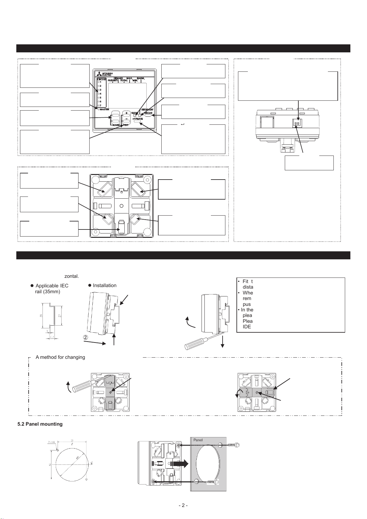
5. Installation
5.1 IEC rail installation
Fix the display unit to IEC rail using IEC rail attachment on the back. Changing the direction of IEC rail attachment, it can attach in both direction of
vertical and horizontal.
Applicable IEC
Installation
rail (35mm)
Push in
②
A method for changing the direction of IEC rail
Removal of the IEC rail attachment
Insert and topple
②
minus driver
5.2 Panel mounting
Cutout dimension
Hook
①
IEC rail
③
Push in IEC rail
stopper upwards.
Remove fixing screw
①
Mounting
Removal
②
Pull up
Fitting of the IEC rail attachment
Push in
②
• Fit the IEC rail with M4 or M5 screws at
distances of 25 to 100 mm.
• When installing the unit after once it was
removed from the IEC rail, install it while
pushing the IEC rail fitting upward.
• In the case of installed plase with much impact,
please pin for stopping missed.
Please use agraffe (model: BNL6) made by
IDEC.
Pull the IEC rail stopper below.
①
Hook the gab of
①
IEC rail attachment
Tighten fixing screw.
③
(Clamping torque: 0.5N-m)
Front view of switching boad
- 2 -
Attach the display unit from front side of
panel, and tighten the screw from the
backside.
(Clamping torque: 0.5N・m)
Page 3
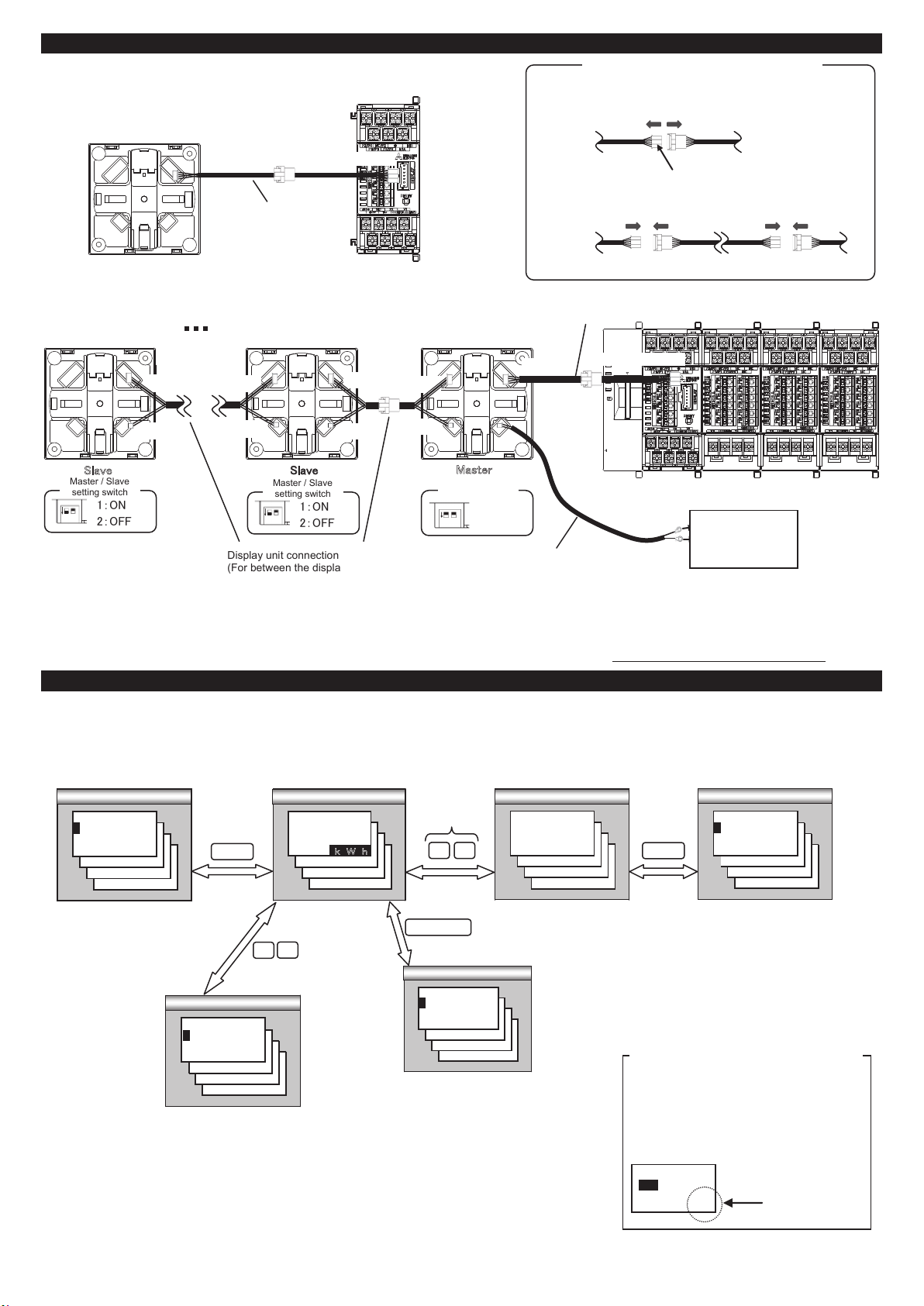
6. Connection method
■1-to-1Connection example
Display unit (EMU4-D65)
OUT 1
OUT 2
IN 1
IN 2
To the socket
“IN 1”
To the socket “DISPLAY”
Connection cable
(bundled in this product)
Energy Measuring Unit
MODEL
EMU4-HM1-MB
Extension method of connecting cable
(1) Remove the trunking connector
Energy Measuring Unit
Remove depressing a lock
(2) Insert the extension cable, and connect the connector
Master
■1-to-N(N≦7)Connection example
Nth unit 2nd unit
Display unit
EMU4-D65
1:ON
2:OFF
IN 1
To the socket
IN 2
To the socket
“IN 1”
“IN 2”
To the socket
“OUT 1”
To the socket
“OUT 2”
Display unit connection cable
(For between the display unit connection)
EMU2-CB1-DP
OUT 1
1
ON
OUT 2
Slave
Master / Slave
setting switch
2
Display unit
EMU4-D65
OUT 1
OUT 2
S
lave
Master / Slave
setting switch
1:ON
2
1
ON
2:OFF
IN 1
To the socket
“IN 1”
IN 2
To the socket
“IN 2”
To the socket
“OUT 1”
To the socket
“OUT 2”
1st unit
Display unit
(bundled in this product)
EMU4-D65
To the socket
IN 1
IN 2
“IN 1”
To the socket
“IN 2”
OUT 1
OUT 2
M
aster
Master / Slave
setting switch
1:OFF
ON
1 2
2:OFF
power supply cable(optional)
EMU4-CB-DPS
Connection cable
Please do firmly insert until it clicks into place
Energy measuring unit
MODEL MODEL
EMU4-HM1-MB
To the socket “DISPLAY”
LOG.
SD CARD
SD C.
BAT.
Model EMU4-LM
BATTERY
EMU4-VA2
DC 9V
MODEL
EMU4-VA2
MODEL
EMU4-VA2
* If the connection is two or more, you must have a power supply from commercial DC power supply(Model:PBA15F-9-N1, made in COSEL CO., LTD.).
Also, the power supply cable (optional : EMU4-CB-DPS) on its connection is required.
* Extension cable(EMU2-CB-T * M), the sum of the length is less than 10m.
The one always in one system is the Master set, Other display unit of, please to Slave conf
iguration. (
The wrong setting and it does not work
)
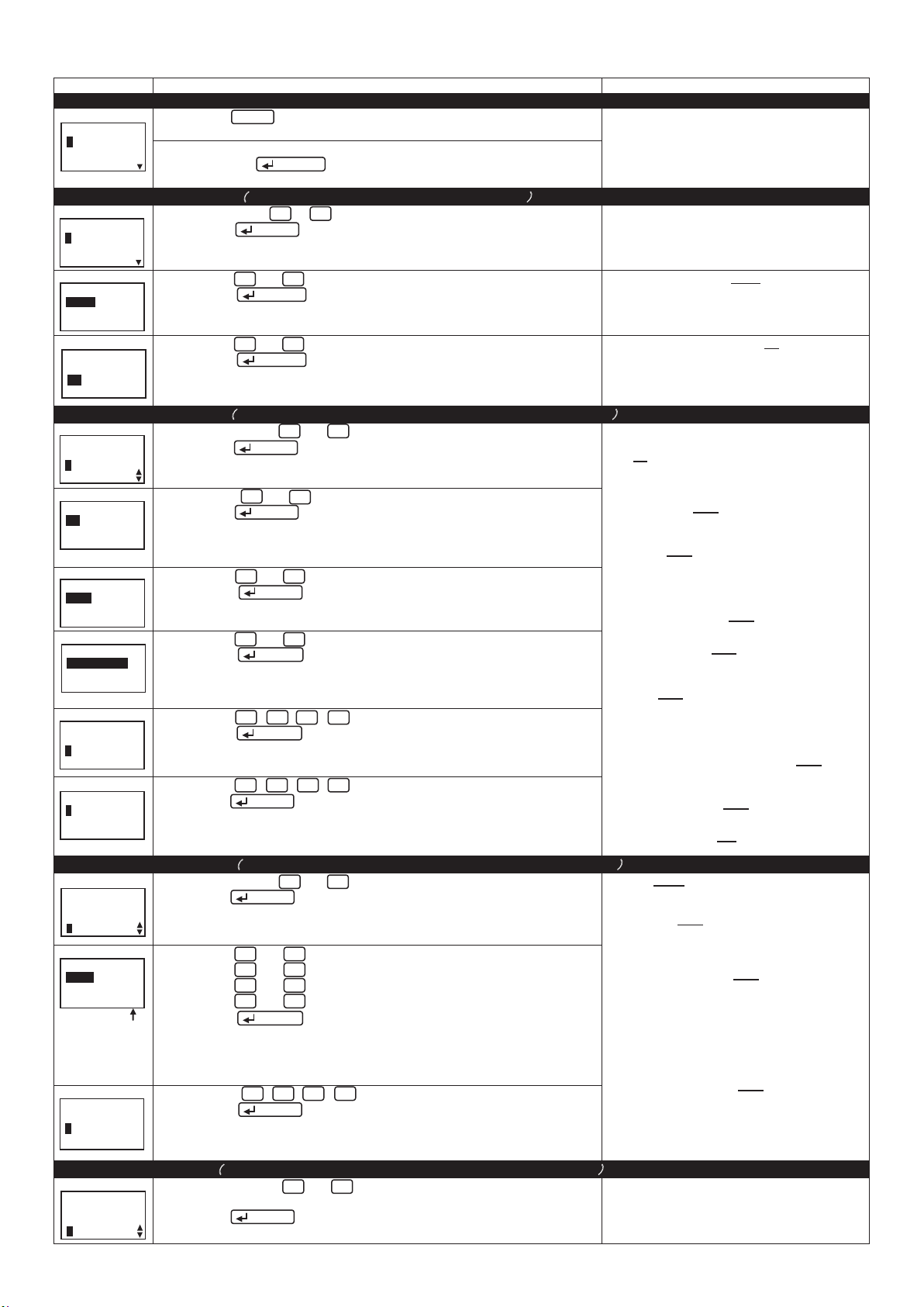
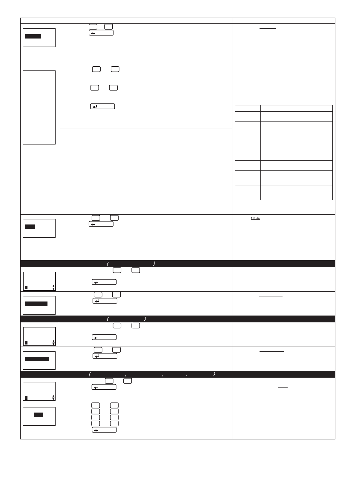
7. Operations of Instrument
7.1 Operation mode
There are following modes of operation. This device is used to switch the operation mode depending on the application. Such as the following, View of
measurement value, Setting for rating, display, clock, Setup for the condition of monitoring, Reset the Max./Min, Data and alarm data, Preset the value
of Wh and varh. Immediately after the power is turned on, it will be the display of the operation mode.
Please refer to 7.2 and 7.3.
Setup Mode
[ S e t up]
M e a s u r e
1
I/O
2
COM.
3
Please refer to the instruction manual
(Detailed
Operation mode
▲
9 9 9 9 9 9
Setup
3
● k W h
x
10
edition)
.
Push 2-buttun at
the same time
▲ ▼
Please refer to the instruction manual
(Detailed edition)
Alarm mode
A l a r m S t at u s
ON
A U pp . ●
Please refer to the instruction manual
(Detailed edition)
Alarm setup mode
[ A l a r m S e t . ]
L i m i t
1
I o / I o r
2
Setup
■
Setting for condition of measurement
(Measurement conditions such as
Wiring,V rate,etc.)
■
Setting for Input/Outpit
■
Setting for Communication
■
Setting for logging
■
Setting for clock
■
Setting for display
■
F/W VER.
Test mode
Test Mode
[ T e s t M ode]
1 C o n n e c t i o n
C O M .
2
3 P u l s e
■
Connection test
■
Pulse output test
■
Alarm output test
■
Communication test
*Test mode is only available when connected the
energy measurement unit (EcoMonitorPlus).
■
Monitoring for
measurement data
Push 2-buttun at
+
-
the same time
Please refer to the instruction
manual(Detailed edition)
■
Monitoring of alarm occurrence
■
Acknowledge the alarm data
Reset/Set
such as occurrence time or value.
Please refer to the instruction manual(Detailed edition)
Reset Mode
[ R e s e t/S e t ]
1
R e s e t
S e t
2
■
Reset the Max./Min. data and alarm data
■
Preset the value of Wh and varh
- 3 -
■
Setup for the condition of upper
and lower supervising
■
Setup for the condition ofmonitoring
leak current alarm
■
Setup for the condition ofmonitoring
instantaneous power failure alarm
■
Setup for the condition of monitoring
breaker alarm
For setting of multiple measuring circuit and CH
2 circuits Measuring
(
EMU4-BM1-MB,EMU4-HM1-MB,EMU4-A2,
EMU4-VA2
)
and
EMU4-PX4,EMU4-AX4 show circuit or CH in
currently displayed.
【Screen example】
[Input]
Non
[1]
Circuit1 or CH1
Page 4
7.2 Setup about rating, clock and display unit in the case of the model to connect the EMU4-**. (Setup mode)
7.2.1 Measuring setup … Setup the measuring condition of the energy measurement unit that is connected. EMU4-PX4 is not set.
Screen Operation Note
1 Transition to the setup mode
1-1.
[Setup]
1 Measure
2 I/O
3 COM.
(1) Push the Setup key in operation mode
(2) 1-1 will be displayed.
(1) Confirm that the cursor focuses the “1 Measure”,
and push the / Phase key.
(2) 2-1 will be displayed
2 Setup the phase wire system(All models except forEMU4-PX4 and EMU4-AX4
2-1.
[Measure]
1 Wiring
2 V rate
3 A rate
2-2.
[Wiring]
3P3W
(1) In 2-1, push the ▲ or ▼ key, and move the cursor to the “1 Wiring”
(2) Push the / Phase key.
(3) 2-2 will be displayed.
(1) Push the + or - key, and change the set value.
(2) Push the / Phase key, and confirm the setting value.
(3) 2-1 will be displayed.
2-3.
[2 circuits
Off
MEA.]
(1) Push the + or - key, and change the set value.
(2) Push the / Phase key, and confirm the setting value.
(3) 2-1 will be displayed.
)
[Wiring]:1P2W⇔1P3W⇔3P3W
*If the basic unit is EMU4-BM1-MB, [Wiring] will be
1P2W, 1P3W, 3P3W only.
*The setting value is set in same voltage system after
confirmed setting value.
[2 circuits Measuring existence]:No
*The setting value is set in same voltage system after
confirmed setting value.
⇔3P4W⇔
⇔Yes⇔
3 Setup the primary voltage(All models except for EMU4-LG1-MB, EMU4-PX4 and EMU4-AX4
3-1.
[Measure]
1 Wiring
2 V rate
3 A rate
3-2.
[VT]
No
(1) In 3-1, push the , and move the cursor to the “2 V rate”.
(2) Push the / Phase key.
(3) 3-2 will be displayed.
(1) Push the + or - key, and select the VT use or non-use.
(2) Push the / Phase key.
(3) Transition to the following screen by the selection of VT use or non-use
or key
▼▲
[No] setting→To 3-3
[YES] setting→To 3-4(If Wiring is 3P4W, transition to 3-5)
3-3.
[Direct V]
220V
(1) Push the + or - key, and change the set value.
(2) Push the / Phase key, and confirm the setting value.
(3) 3-1 will be displayed.
3-4.
[Primary V]
440V
(1) Push the +or -key, and change the set value.
(2) Push the / Phase key, and confirm the setting value.
(3) transition to the following screen by the setting value of the primary voltage
[SP] setting → To 3-5
Non-[SP] setting → To 3-1
3-5.
[SP.PRI.V]
000440V
3-6.
[SP.2nd.V]
220V
(1) Push the
▼▲
+ -
key, and change the set value.
(2) Push the / Phase key, and confirm the setting value.
(3) 3-6 will be displayed.
(1) Push the
+ -
▼▲
key, and change the set value.
(2) Push the / Phase key, and confirm the setting value.
(3) 3-1 will be displayed.
4 Setup the primary current (All models except for EMU4-LG1-MB, EMU4-PX4 and EMU4-AX4
4-1.
[Measure]
1 Wiring
2 V rate
3 A rate
4-2.
[Sensor]
Direct
[PRI A]
100A [1]
1P2W only
(1) In 4-1, Push the , and move the cursor to the “3 A rate”.
or key
▼▲
(2) Push the / Phase key.
(3) 4-2 will be displayed.
(1) Push the and move the cursor to the “Sensor” side.
(2) Push the + or
(3) Push the and move the cursor to the “PRI A” side.
(4) Push the + or -key,
or
or
key,
▼▲
key, and select sensor type.
-
▼▲
key,
and change the primary current value.
(5) Push the / Phase key, and confirm the setting value.
(6) Transition to the following screen by the setting wiring type and primary
current value.
[SP] setting → To 4-3
Non-[SP] setting → To 4-1
4-3.
[SP.PRI.A]
001000A
[1]
(1) Push the ▲ ▼ + - key, and change the set value.
(2) Push the / Phase key, and confirm the setting value.
(3) 4-1 will be displayed.
)
*The setting value is set in same voltage system after
confirmed setting value.
[VT]:No
⇔Yes⇔
*1P3W is “No” fixed.
1P2W, 3P3W ---------------------------------When [VT]:“No” setting
[Direct V]:110V⇔220V
*If the basic unit is EMU4-BM1-MB, [Direct V] will be
110V,220V only.
When [VT]:“Yes” setting
[Primary V]:440V
When [Primary V]
[SP.PRI.V]:1~110000V(440V
(1~99V:Can be set in the 1V step.)
(100~110000V:Can be set in the 100V step.)
[SP.2nd.V]:1~220V(110V
(Can be set in the 1V step.)
1P3W ---------------------------------------“No” fixed
[Direct V]:110V
*If the basic unit is EMU4-BM1-MB, [Direct V] will be
110V
3P4W --------------------------------------When [VT]:“Yes” setting
[Direct V] :63.5V ⇔100V ⇔105V ⇔110V ⇔ 115V ⇔
When [VT]:“Yes” setting
[SP.PRI.V]:1~63500V(440V
(1~99V:Can be set in the 1V step.)
(100~63500V:Can be set in the 100V step.)
[SP.2nd.V]:1~220V(64V
(Can be set in the 1V step.)
6600V⇔11000V⇔13200V⇔13800V⇔
15000V⇔16500V⇔22000V⇔24000V⇔
33000V⇔66000V⇔77000V⇔110000V⇔
SP⇔
⇔440V*⇔
⇔690V⇔1100V⇔2200V⇔3300V⇔
settingand SP setting
⇔220V*⇔
120V⇔127V⇔200V⇔220V
240V⇔242V⇔250V⇔254V⇔ 265V⇔
277V⇔
)
)
⇔230V⇔
)
)
)
[Sensor]:Direct
When “Direct” setting
[PRI A]:50A⇔100A
When “5A” setting
[PRI A]:5A⇔6A⇔7.5A⇔8A⇔10A⇔12A⇔15A
[SP.PRI.A] :5.0~30000A(
10A less than, the upper two digits.
10A or more is possible to set the upper three digits.
⇔5A⇔
⇔250A⇔400A⇔600A⇔
⇔20A⇔25A⇔30A⇔40A⇔50A⇔60A
⇔75A⇔80A⇔
⇔250A⇔300A⇔400A⇔500A⇔600A
⇔750A⇔800A⇔1000A⇔1200A⇔1250A
⇔1500A⇔1600A⇔2000A⇔2500A
⇔3000A⇔4000A⇔5000A⇔6000A
⇔7500A⇔8000A⇔10000A⇔12000A
⇔20000A⇔25000A⇔30000A⇔SP⇔
100A
⇔120A⇔150A⇔200A
100A
)
5 Setup the display mode(All models except for EMU4-LG1-MB, EMU4-PX4 and EMU4-AX4
5-1.
[Measure]
2 V rate
3 A rate
4 DISP.Mode
(1) In 5-1, push the or key, and move the cursor to the
▲
▼
“4 DISP.Mode”.
(2) Push the / Phase key.
(3) 5-2 will be displayed.
- 4 -
)
Set the measurement elements to be displayed in the
display unit.
Page 5
Screen Operation Note
5-2.
[DISP.Mode]
Wh+A+4
Harmonics
(1) Push the ▲ or ▼ key, and select the display mode.
(2) Push the / Phase key.
(3) Transition to the following screen by the selection of measurement mode.
[Wh+A+4] setting → To 5-3
[Harmonics] setting → To 5-4
5-3.
[Element]
V
W
var
VA
PF
Hz
CONV.Wh
PRD.Wh
OP.Time
REG.Wh
varh
PLS
UNB.A
UNB.V
HA
HV
5-4.
[HA,HV]
r.m.s.
(1) Push the ▲ or ▼ key, and move the cursor to target element.
(In the actual display, it will be scrolling display of each three elements
in one screen.)
(2) Push the + or - key, and choose the selected or desselected.
(3) When selecting the other measurement item, repeat the operation from
(1) to (2).
(4) Push the /Phase key, and determine the setting.
(5) Transition to the following screen by the selection of measurement mode.
Not check “HA” and “HV”→ To 5-1
“HA” or “HV” → To 5-4
Check
*Elements is showed follow.
V:Voltage
W:Electric power
var:reactive power
VA:apparent power
PF:Power factor
Hz:frequency
Wh converted value:Electric energy (converted)
Periodic Wh:Electric energy (regeneration)
Regenerated Wh:Periodic electric energy
varh:Reactive energy (consumption lag)
PULSE:Pulse count value and pulse converted value
UNB.A:Current unbalance rate
UNB.V:Voltage unbalance rate
HA:Harmonics current
HV:Harmonics voltage
(1) Push the ▲ or ▼ key , and change the “HA,HV” value.
(2) Push the / Phase key.
(3) 5-1 will be displayed.
6(1)Setup the measurement mode (EMU4-LG1-MB only
6(1)-1.
[Measure]
3 A rate
4 DISP.Mode
5 MEA.Mode
6(1)-2.
[MEA.Mode]
High SENS.
Low SENS.
(1) In 6(1)-1, push the ▲ or ▼ key, and move the cursor to the
“5 MEA.Mode”.
(2) Push the / Phase key.
(3) 6(1)-2 will be displayed.
(1) Push the ▲ or ▼ key, and select the measurement mode.
(2) Push the / Phase key.
(3) 6(1)-1 will be displayed.
6(2)Setup the measurement mode (EMU4-AX4 only
6(2)-1.
[Measure]
3 A rate
4 DISP.Mode
5 MEA.Mode
6(2)-2.
[MEA.Mode]
50ms SAMP.
1ms SAMP.
(1) In 6(2)-1, push the ▲ or ▼ key, and move the cursor to the
“5 MEA.Mode”.
(2) Push the / Phase key.
(3) 6(2)-2 will be displayed.
(1) Push the ▲ or ▼ key, and select the measurement mode.
(2) Push the / Phase key.
(3) 6(2)-1 will be displayed.
)
)
[DISP.Mode]:Wh+A+4⇔Harmonics⇔
*In case of the model EMU4-BM1-MB , the
“
Harmonics” not be displayed.
Wh+A+4…In addition to the active energyand current,
Harmonics…It can display aboutharmonic data
[Element]:V, W, var, VA, PF, Hz, CONV.Wh, PRD.Wh,
OP.Time, REG.Wh, varh, CONV.PLS, UNB.V, HA, HV
(Deselected), (Selected)
*The selectable number of elements is up to 4. So,
* Elements can't select in follow table.
[HA,HV]:r.m.s.⇔%
*
r.m.s.… to display the RMS value of harmonic current
%… to display the distortion rate and content rate of
Setup the measurement mode of “Io” or ”Ior”.
[MEA.Mode]:High SENS.⇔Low SENS.⇔
Low SENS.…0~1000mA1mAstep
High SENS.…0.00~100mA 0.01mAstep
Setup the measurement mode of AD converted.
[MEA.Mode]:50ms SAMP.⇔1ms SAMP.⇔
50ms SAMP.…AD converted in a cycle of 50ms.
1ms SAMP.…AD converted in a cycle of 1ms.
up to 4 items can bedisplayed by selection.
(The harmonics data is only about total.)
at each order.
change the selection at the statethat already 4 items
are selected, deselectthe items before changing.
Element
UNB.A
UNB.V
Periodic WhIn the case of EMU4-BM1-MB,
Pulse In the case EMU4-BM1-MB,
HA
HV
VA In the case EMU4-BM1-MB,
Wh
converted
value
In case of the model EMU4-BM1-MB, “HA,HV” can
not be set.
or harmonic voltage.
In the case can not select
In the case of setting simplicity
measuring mode
EMU4-A2, EMU4-VA2.
External input is not contact input.
EMU4-A2, EMU4-VA2.
Pulse input is not contact input.
In the case EMU4-BM1-MB.
Wiring is 1P2W,1P3W or 3P3W
In the case EMU4-BM1-MB
(The “%” not be displayed.)
harmonic current or harmonic voltage.
(The “r.m.s.”
not be displayed.)
7(1) Setup the demand time(EMU4-BM1-MB、EMU4-HM1-MB、EMU4-A2、EMU4-VA2
7(1)-1.
[Measure]
4 DISP.Mode
5 MEA.Mode
6 Demand
7(1)-2.
[Demand]
A : 2min
W : 2min
(1) In 7-1, push the ▲ or ▼ key, and move the cursor to the “6 Demand”.
(2) Push the / Phase key.
(3) 7(1)-2 will be displayed.
(1) Push the ▲ or ▼ key, and move the cursor to the A(Current).
(2) Push the + or - key, and change the demand time value.
(3) Push the ▲ or ▼ key, and move the cursor to the W(Electric power).
(4) Push the + or - key, and change the demand time value.
(5) Push the / Phase key , and confirm the setting value.
(6) 7(1)-1 will be displayed.
- 5 -
- 5 -
)
[Demand]:0sec⇔10sec⇔20sec⇔30sec⇔40sec⇔
50sec⇔1min⇔2min
⇔6min⇔7min⇔8min⇔9min⇔10min⇔
11min⇔12min⇔13min⇔14min⇔ 15min⇔
20min⇔25min⇔30min⇔
⇔3min⇔4min⇔5min
Page 6

Screen Operation Note
7(2) Setup the demand time(EMU4-LG1-MB
7(2)-1
[Measure]
4 DISP.Mode
5 MEA.Mode
6 Demand
7(2)-2
[Demand]
Io/Ior: 5min
(1) In 7(2)-1, push the ▲ or ▼ key, and move the cursor to
the “6 Demand”.
(2) Push the / Phase key and
(3) 7(2)-2 will be displayed.
(1) Push the + or - key, and change the Io/Ior demand time value.
(2) Push the / Phase key, and confirm the setting value.
(3) 7(2)-1 will be displayed.
)
[Demand]:0sec⇔5min⇔6min⇔7min⇔8min⇔9min⇔
10min⇔11min⇔12min⇔13min⇔14min⇔
15min⇔20min⇔25min⇔30min⇔
8 Setup the electric energy equivalent rate(All models except for EMU4-LG1-MB
8-1.
[Measure]
5 MEA.Mode
6 Demand
7 CONV.Wh
8-2.
[CONV.Rate]
1.000
[Unit]
Non [1]
(1) In 8-1, push the ▲ or ▼ key, and move the cursor to the
“7 CONV.Wh”
(2) Push the / Phase key.
(3) 8-2 will be displayed.
(1) Push the
▲ ▼
-key, and change the “CONV.Rate” value and
+
unit.
(2) Push the / Phase key , and confirm the setting value.
(3) Transition to the following screen by the setting wiring type.
)
[CONV.Rate]:0.001~10000(1.000)
[Unit]:Non
2 circuit measurement → To 8-3
non-2 circuit measurement → To 8-1
8-3.
[CONV.Rate]
1.000
[Unit]
Non [2]
(1) In a similar way as 8-2, change the “CONV.Rate” value and unit of the
second circuit.
(2) Push the / Phase key, and confirm the setting value.
(3) 8-1 will be displayed.
9 Setup the current cut-off rate(All models except for EMU4-LG1-MB, EMU4-PX4 and EMU4-AX4
9-1.
[Measure]
6 Demand
7 CONV.Wh
8 A Cut-off
9-2.
[A Cut-off]
00.5%
9-3.
[A Cut-off]
00.5%
(1) In 9-1,push the ▲ or ▼ key , and move the cursor to the
“8 A Cut-off”.
(2) Push the / Phase key.
(3) 9-2 will be displayed.
(1) Push the + or - key, and change the set value.
(2) Push the / Phase key , and confirm the setting value.
(3) Transition to the following screen by the setting wiring type.
[1]
2 circuit measurement → To 9-3
non-2 circuit measurement → To 9-1
(1) In a similar way as 9-2, change the “A Cut-off” value of the second circuit.
(2) Push the / Phase key, and confirm the setting value.
(3) 9-1 will be displayed.
[2]
[
A Cut-off]:0.1~50.0%(0.5)
A cut-off rate…represent as the ratio of cut-off current
※Measured value is 0A if it is less than the
cut-off current.
10 Setup the Simple measurement (All models except for EMU4-LG1-MB, EMU4-PX4 and EMU4-AX4
10-1.
[Measure]
7 CONV.Wh
8 A Cut-off
9 SimpleMEA
10-2.
[SimpleMEA]
Off
10-3.
[FP Set]
1.000
(1) In 10-1, push the ▲ or ▼ key, and move the cursor to the
“9 SimpleMEA”.
(2) Push the / Phase key.
(3) 10-2 will be displayed.
(1) Push the + or - key, and select SimpleMEA([On]/[Off]).
(2) Push the / Phase key, and confirm the setting value.
(3) Transition to the following screen by the setting SimpleMEA([On]/[Off])
[On]
setting → To 10-3
[
Off] setting → To 10-1
(1) Push the
▲ ▼
+ - key, and change the power factor value
In the SimpleMEA.
(2) Push the / Phase key,and confirm the setting value.
[1]
(3) Transition to the following screen by the setting wiring type.
[SimpleMEA]:Off⇔On⇔
SimpleMEA…The value set in the electric power and
[FP Set]:-0.001~1.000~0.000
2 circuit measurement → To 10-4
non-2 circuit measurement → To 10-1
10-4.
[FP Set]
1.000
11 Setup the Ior difference conversion(EMU4-LG1-MB only
11-1.
[Measure]
8 A Cut-off
9 SimpleMEA
10 DIF.CONV
11-2.
[
DIF.CONV
Off
(1) In a similar way as 10-3, change the power factor value of the second circuit.
(2) Push the / Phase key, and confirm the setting value.
(3) 10-1 will be displayed.
[2]
)
(1) In 11-1, push the ▲ or ▼ key , and move the cursor to the
“10 DIF.CONV”.
(2) Push the / Phase key.
(3) 11-2 will be displayed.
(1) Push the + or - key, and select the Ior difference converted value
]
([On]/[Off])
(2) Push the / Phase key, and confirm the setting value.
[DIF.CONV]:Off⇔On⇔
DIF.CONV…To calculate the amount of change from
(3) Transition to the following screen by the setting DIF.CONV([On]/[Off]).
[On]
setting → To 11-3
[
Off] setting → To 11-1
⇔Wh⇔kWh⇔MWh⇔J⇔m2⇔m3⇔L⇔
kL⇔sec⇔min⇔hour⇔piece⇔set⇔g⇔kg⇔
t⇔¥⇔$⇔
)
to rated current.
)
the power factor as the fixed value.
By measuring the current only, and
calculating the values of the measurement
elements.
the Ior difference converted value.
- 6 -
Page 7

Screen Operation Note
11-3.
[DIF.Ior]
0.00 mA
(1) Push the ▲ ▼ + - key, and change the Ior difference converted
reference value.
(2) Push the / Phase key,and confirm the setting value.
(3) 11-1 will be displayed.
12 Setup the AD Converted(EMU4-AX4 only
12-1.
[Measure]
9 SimpleMEA
10DIF.CONV.
11AD CONV.
12-2.
[AD CONV.]
On
(1) In 12-1, push the ▲ or ▼ key, and move the cursor to the
“11 AD CONV.”.
(2) Push the / Phase key.
(3) 12-2 will be displayed.
(1) Push the + or - key, and select the AD converted([On]/[Off]).
(2) Push the / Phase key, and confirm the setting value.
(3) Transition to the following screen by the setting AD CONV.([On]/[Off])
[1]
[On] setting → To 12-3
)
High SENS mode
[DIF.Ior]:0.00
Low SENS mode
[DIF.Ior]:0
[AD CONV.]:Off⇔ ⇔
AD CONV.…The setting value is set inAD convert per
~100.00mA
~1000mA
CH.
[Off] setting → To 12-6
12-3.
[Range]
Current
12-4.
[Moving
average]
001 times
12-5.
[Scaling]
Upp.: 04095
Low.: 00000
Unit:Non [1]
12-6.
[AD CONV.]
On
(1) Push the + or - key, and select the input range.
(2) Push the / Phase key, and confirm the setting value.
(3) 12-4 will be displayed.
[1]
(1) Push the ▲ ▼ + - key, and change the number of moving
average.
(2) Push the / Phase key, and confirm the setting value.
[1]
(3) 12-5 will be displayed.
(1) Push the ▲ ▼ + - key, and change the upper limit, lower limit,
and unit.
(2) Push the / Phase key, and confirm the setting value.
(3) 12-6 will be displayed.
(1) Push the + or - key, and select the AD converted([On]/[Off]).
(2) Push the / Phase key, and confirm the setting value.
(3) Transition to the following screen by the setting AD CONV.([On]/[Off])
[2]
[On] setting → To 12-7
[Range]:Current⇔Voltage⇔
[Moving average]:001~100(001
[Upp]:-32767~32767(4095)
[Low]:-32767~32767(0)
[Unit]:Non
⇔A⇔mA⇔kA⇔V⇔kV⇔W⇔kW⇔MW⇔Hz⇔N⇔
kN⇔Pa⇔kPa⇔MPa⇔C⇔deg⇔%⇔
[Off] setting → To 12-10
12-7.
[Range]
Current
12-8.
[Moving
average]
001 times
12-9.
[Scaling]
Upp.: 04095
Low.: 00000
Unit:Non [2]
12-10.
[AD CONV.]
On
(1) Push the + or - key, and select the input range.
(2) Push the / Phase key, and confirm the setting value.
(3) 12-8 will be displayed.
[2]
(1) Push the ▲ ▼ + - key, and change the number of moving
average.
(2) Push the / Phase key, and confirm the setting value.
[2]
(3) 12-9 will be displayed.
(1) Push the ▲ ▼ + - key, and change the upper limit, lower limit,
and unit.
(2) Push the / Phase key, and confirm the setting value.
(3) 12-10 will be displayed.
(1) Push the + or - key, and select the AD converted([On]/[Off]).
(2) Push the / Phase key, and confirm the setting value.
(3) Transition to the following screen by the setting AD CONV.([On]/[Off])
[3]
[On] setting → To 12-11
[Off] setting → To 12-14
12-11.
[Range]
Current
12-12.
[Moving
average]
001 times
12-13.
[Scaling]
Upp.: 04095
Low.: 00000
Unit:Non [3]
12-14.
[AD CONV.]
On
(1) Push the + or - key, and select the input range.
(2) Push the / Phase key, and confirm the setting value.
(3) 12-12 will be displayed.
[3]
(1) Push the ▲ ▼ + - key, and change the number of moving
average.
(2) Push the / Phase key, and confirm the setting value.
[3]
(3) 12-13 will be displayed.
(1) Push the ▲ ▼ + - key, and change the upper limit, lower limit,
and unit.
(2) Push the / Phase key, and confirm the setting value.
(3) 12-14 will be displayed.
(1) Push the + or - key, and select the AD converted([On]/[Off]).
(2) Push the / Phase key, and confirm the setting value.
(3) Transition to the following screen by the setting AD CONV.([On]/[Off])
[4]
[On] setting → To 12-15
[Off] setting → To 12-1
12-15.
[Range]
Current
12-16.
[Moving
001 times
average]
(1) Push the + or - key, and select the input range.
(2) Push the / Phase key, and confirm the setting value.
(3) 12-16 will be displayed.
[4]
(1) Push the
▲ ▼
- key, and change the number of moving
+
average.
(2) Push the / Phase key, and confirm the setting value.
[4]
(3) 12-17 will be displayed.
On
)
- 7 -
Page 8

Screen Operation Note
12-17.
[Scaling]
Upp.: 04095
Low.: 00000
Unit:Non [4]
(1) Push the
limit, and unit.
(2) Push the / Phase key, and confirm the setting value.
(3) 12-1 will be displayed.
13 Setup the Number Limit(EMU4-AX4 only
13-1.
[Measure]
10DIF.CONV.
11AD CONV.
12Num.Limit
(1) In 13-1, push the ▲ or ▼ key, and move the cursor to the
“12 Num.Limit”.
(2) Push the / Phase key.
(3) 13.1-1 will be displayed.
▲ ▼
+
- key, and change the scalling upper limit, lower
)
13.1 Setup the Limit A, Limit B, Limit C, and Limit D(EMU4-AX4 only
13.1-1.
[Num.Limit]
1 Limit A
2 Limit B
3 Limit C
13.1-2.
[Limit A]
-32767
13.1-3.
[Limit A]
-32767
13.1-4
[Limit A]
-32767
13.1-5
[Limit A]
-32767
13.2 Setup the multiplying factor(EMU4-AX4 only
13.2-1.
[Num.Limit]
3 Limit C
4 Limit D
5 Factor
13.2-2.
[Factor]
x1
13.2-3.
[Factor]
x1
13.2-4
[Factor]
x1
13.2-5
[Factor]
x1
(1) In 13.1-1, push the ▲ or ▼ key, and move the cursor to the
“1 Limit A”.
(2) Push the / Phase key.
(3) 13.1-2 will be displayed.
(1) Push the ▲ ▼ + - key, and change the set value.
(2) Push the / Phase key.
(3) 13.1-3 will be displayed.
[1]
(1) Push the ▲ ▼ + - key, and change the set value.
(2) Push the / Phase key.
(3) 13.1-4 will be displayed.
[2]
(1) Push the ▲ ▼ + - key, and change the set value.
(2) Push the / Phase key.
(3) 13.1-5 will be displayed.
[3]
(1) Push the ▲ ▼ + - key, and change the set value.
(2) Push the / Phase key.
(3) 13.1-1 will be displayed.
[4]
)
(1) In 13.2-1, push the ▲ or ▼ key, and move the cursor to the
“5 Factor”.
(2) Push the / Phase key.
(3) 13.2-2 will be displayed.
(1) Push the + or - key, and select the multiplying factor displayed.
(2) Push the / Phase key.
(3) 13.2-3 will be displayed.
[1]
(1) Push the + or - key, and select the multiplying factor displayed.
(2) Push the / Phase key.
(3) 13.2-4 will be displayed.
[2]
(1) Push the + or - key, and select the multiplying factor displayed.
(2) Push the / Phase key.
(3) 13.2-5 will be displayed.
[3]
(1) Push the + or - key, and select the multiplying factor displayed.
(2) Push the / Phase key.
(3) 13.2-1 will be displayed.
[4]
)
[Upp]:-32767~32767(4095)
[Low]:-32767~32767(0)
[Unit]:Non
Num.Limit…Set any limint .
*If the scaling value over the limit, Number Limit
Limit B, Limit C, and Limit D is done in the same way
as the setting of Limit A.
Limit…Set any scalling value.
[Limit A]:Scaling Low~Scaling Upp
*If scaling setting value is set “Scaling Low > Scaling
Upp”, default setting is Scaling Upp.
[Factor]:x1⇔x10⇔x100⇔x1000⇔
Factor…Set up the multiplying factor displayed of
⇔A⇔mA⇔kA⇔V⇔kV⇔W⇔kW⇔MW⇔Hz⇔N⇔
kN⇔Pa⇔kPa⇔MPa⇔C⇔deg⇔%⇔
countup.
You can configure the four different limits for
limit A, limit B, limit C, and limit D.
Number Limit.
14 Save the settings
14-1.
Quit Setup
1 Save
2 Not Save
3 Cancel
14-2.
Completed
*Setting for condition of the measurement mode can only configure in the display unit is set to master.(Setting for condition of the measurement mode can not configure in
the display unit is set to slave.)
*If you change a settings, please push the / Phase key and be sure to determine changes. If without determine, the changes will be discarded.
*The underline means the default of setting. After you have been set, even if a power failure occurs does
*If you want to set the other circuit, push the Circuit key on the "Setup" screen (1-1), select the circuit, make the setting.
*Same voltage system is same setting in wire system, primary voltage, 2 circuits Measuring existence, Simple measurement.
(1) After setting all of the items, and push the Setup key.
(2) 14-1 will be displayed.
(3) When save the settings, push the ▲ or ▼ key, move the cursor to
the “1 Save”, and push the / Phase key.
(4) After completing the settings saving, 14-2 will be displayed.
Push the /Phase key.
(5) Return to the operation mode.
OK
not disappear setting.
1 Save → Save settings and return to
2 Not Save → Discard the changes and
3 Cance
the operation mode.
return to the operation mode.
l →Continue the setup.
7.2.2 Input/Output setup-the settings for the external Input/Output. EMU4-LG1-MB is not set.
Screen Operation Note
1 Transit to the Setup mode
1-1.
[Setup]
1 Measure
2 I/O
3 COM.
(1) Push the Setup key in operation mode.
(2) 1-1 will be displayed.
(1) Push the ▲ or ▼ key, and move the cursor to the ”2 I/O”.
Push the / Phase key.
(2) 2-1 will be displayed.
- 8 -
Page 9

Screen Operation Note
2 Setup input (EMU4-HM1-MB, EMU4-PX4
2-1.
[I/O]
1 Input
2 OP.Time
3 Output
2-2.
[Input]
[Input]
Non
Non
(1) In 2-1, Push the ▲ or ▼ key , and move the cursor to the ”1 Input”.
(2) Push the / Phase key.
(3) 2-2 will be displayed.
(1) Push the + or - key , and select the input method.
(Non/ Contact /Pulse)
(2) Push the / Phase key.
[1]
[1]
(3) Transition to the following screen by the model and setting input method.
[Non] setting
EMU4-PX4 only
Model:EMU4-HM1-MB → To 2-1
Model:EMU4-PX4 → To 2-5
[Pulse] setting → To 2-3
[Contact] setting → To 2-4
2-3.
[CONV.Rate]
[CONV.Rate]
1.000
1.000
[Unit]
[Unit]
Non [1]
Non [1]
EMU4-PX4 only
2-4.
[ResetMode]
[ResetMode]
Auto
Auto
EMU4-PX4 only
2-5.
[Input]
Non
(1) Push the ▲ ▼ + - key, and change the “CONV.Rate” value
and unit.
(2) Push the / Phase key, and confirm the setting value.
(3) Transition to the following screen by the model.
Model:EMU4-HM1-MB → To 2-1
Model:EMU4-PX4 → To 2-5
(1) Push the + or - key, and select thereset mode.
(2) Push the / Phase key.
(3) Transition to the following screen by the model.
[1]
[1]
Model:EMU4-HM1-MB → To 2-1
Model:EMU4-PX4 → To 2-5
(1) Push the + or - key , and select the input method.
(Non/ Contact /Pulse)
(2) Push the / Phase key.
[2]
(3) Transition to the following screen by the setting input method.
)
<EMU4-HM1-MB>
[Input]:Non
<EMU4-PX4>
[Input]:Pulse
[CONV.Rate]:0.001~10000(1.000)
[Unit]:Non
[ResetMode]:Auto
Auto…Contact input state is reset automaticaly when
Hold…Contact input state is hold until contact input
⇔Contact⇔Pulse⇔
⇔Contact⇔Non⇔
⇔Wh⇔kWh⇔MWh⇔J⇔m2⇔m3⇔L⇔
kL⇔sec⇔min⇔hour⇔個⇔台⇔g⇔kg⇔t⇔
¥⇔$⇔
contact input is less.
released even thought contact input is less.
(For information about how to release of the
contact input, please refer to the instruction
manual (Detailed edition))
[Non] setting → To 2-8
[Pulse] setting → To 2-6
[Contact] setting → To 2-7
2-6.
[CONV.Rate]
1.000
[Unit]
Non [2]
2-7.
[ResetMode]
Auto
2-8.
[Input]
Non
(1) Push the ▲ ▼ + - key, and change the “CONV.Rate” value
and unit.
(2) Push the / Phase key, and confirm the setting value.
(3) 2-8 will be displayed.
(1) Push the + or - key, and select thereset mode.
(2) Push the / Phase key.
(3) 2-8 will be displayed.
[2]
(1) Push the + or - key , and select the input method.
(Non/ Contact /Pulse)
(2) Push the / Phase key.
[3]
(3) Transition to the following screen by the setting input method.
[Non] setting → To 2-11
[Pulse] setting → To 2-9
[Contact] setting → To 2-10
2-9.
[CONV.Rate]
1.000
[Unit]
Non [3]
2-10.
[ResetMode]
Auto
2-11.
[Input]
Non
(1) Push the
and unit.
(2) Push the / Phase key, and confirm the setting value.
(3) 2-11 will be displayed.
(1) Push the + or - key, and select thereset mode.
(2) Push the / Phase key.
(3) 2-11 will be displayed.
[3]
(1) Push the + or - key , and select the input method.
(Non/ Contact /Pulse)
(2) Push the / Phase key.
[4]
(3) Transition to the following screen by the setting input method.
▲ ▼
+ - key, and change the “CONV.Rate” value
[Non] setting → To 2-1
[Pulse] setting → To 2-12
[Contact] setting → To 2-13
2-12.
[CONV.Rate]
1.000
[Unit]
Non [4]
2-13.
[ResetMode]
Auto
(1) Push the ▲ ▼ + - key, and change the “CONV.Rate” value
and unit.
(2) Push the / Phase key, and confirm the setting value.
(3) 2-1 will be displayed.
(1) Push the + or - key, and select thereset mode.
(2) Push the / Phase key.
(3) 2-1 will be displayed.
[4]
⇔Hold⇔
- 9 -
Page 10

Screen Operation Note
3 Setup the operation time measurement
3-1.
[I/O]
1 Input
2 OP.Time
3 Output
3-2.
[OP.Time]
Off
(1) In 3-1, Push the ▲ or ▼ key, and move the cursor to the
“2 OP.Time”.
(2) Push the / Phase key.
(3) 3-2 will be displayed.
(1) Push the + or - key, and select the operation time measurement.
(On/Off)
(2) Push the / Phase key.
[1]
(3) Transition to the following screen by the model, and setting wiring type and
existence of the operation time measurement.
Model:EMU4-PX4 or
2 circuits measuring
only
Model:EMU4-PX4 → To 3-4
Model:Other than EMU4-PX4
2 circuit measurement and [Off] setting → To 3-4
non-2 circuit measurement and [Off] setting → To 3-1
[On]
3-3.
[OP.Time
Mode]
A
2 circuits measuring
only
3-4.
[OP.Time]
Off
(1) Push the + or - key, and select the operation time measurement
mode.
(2) Push the / Phase key.
[1]
(3) Transition to the following screen by the setting wiring type.
2 circuit measurement → To 3-4
non-2 circuit measurement → To 3-1
(1) Push the + or - key, and select the operation time measurement.
(2) Push the / Phase key.
(3) Transition to the following screen by the model, and setting existence of the
[2]
operation time measurement.
setting → To 3-3
(
All models except for EMU4-LG1-MB
)
[OP.Time]:Off⇔On⇔
EMU4-HM1-MB
[OP.Time Mode]:A
EMU4-BM1-MB, EMU4-A2, EMU4-VA2
[OP.Time Mode]:A
EMU4-PX4
Input setting value is set contact, this CH is not
displayed.
Operating time is integrated time while the current
measured value is higher than the rated current,
Current cut-off rate when select A.
Operating time is integration time while Contact input
is ON when Contact input.
Model:EMU4-PX4 → To 3-6
Model:Other than EMU4-PX4
[
Off] setting → To 3-1
[On]
3-5.
[OP.Time
Mode]
A
3-6.
[OP.Time]
Off
3-7.
[OP.Time]
Off
(1) Push the +or - key, and select the operation time measurement
mode.
(2) Push the / Phase key.
[2]
(3) 3-1 will be displayed.
(1) Push the+ or
(2) Push the / Phase key.
(3) 3-7 will be displayed.
[3]
(1) Push the + or - key, and select the operation time measurement.
(2) Push the / Phase key.
(3) 3-1 will be displayed.
[4]
4 Setup Output (EMU4-HM1-MB, EMU4-A2, EMU4-VA2, EMU4-PX4, EMU4-AX4
4-1.
[I/O]
1 Input
2 OP.Time
3 Output
4-2.
[Output]
Non
(1) In 4-1, Push the ▲ or ▼ key, and move the cursor to the ”3 Output”.
(2) Push the / Phase key.
(3) 4-2 will be displayed.
(1) Push the +or - key, and select the output signal type.
(2) Push the / Phase key.
(3) Transition to the following screen by the model, and setting wiring type and
the output signal type.
Model:EMU4-PX4 or EMU4-AX4 → To 4-1
Model:EMU4-HM1-MB, EMU4-A2 or EMU4-VA2
setting → To 3-5
key, and select the operation time measurement.
-
[Non] setting → To 4-1
2 circuit measurement and [Pulse] setting → To 4-3
)
EMU4-HM1-MB, EMU4-A2, EMU4-VA2
[Output]:Non
EMU4-PX4, EMU4-AX4
[Output]:Non
The pulse output unit changes by the full load power.
[Pulse]:
Full load power (kW) Setting range
Wfull<12kW
12kW ≤ Wfull < 120kW
120kW ≤ Wfull < 1200kW
1200kW ≤ Wfull < 12000kW
12000kW ≤ Wfull < 120000kW
120000kW ≤ Wfull
⇔Pulse⇔Alarm⇔
⇔Alarm⇔Contact⇔
non-2 circuit measurement and [Pulse] setting → To 4-4
2 circuit measurement and [Alarm] setting → To 4-3
4-3
[Output]
[ 1 ]
4-4.
[Pulse]
0.01
kWh/Pulse
non-2 circuit measur
(1) Push the + or - key, and select the output target.
(2) Push the / Phase key.
(3) Transition to the following screen by setting output signal type.
[Pulse] setting → To 4-4
[Alarm] setting → To 4-1
(1) Push the ▲
▼
(2) Push the / Phase key. Confirm the setting value.
(3) 4-1 will be displayed.
ement and [Alarm] setting → To 4-1
+ -
key, and change the pulse output unit.
[Output]:1⇔2⇔
It is set which circuit it does external output, because
*
it inputs 2 circuits per a terminal block for 1P2W.
If the target of external output is 1K, 1L connection
side circuit, Set “1”.
If the target of external output is 3K, 3L connection
side circuit, Set “2”.
⇔x⇔
0.001
0.01
0.1
1
⇔10⇔100⇔1000⇔
10
100
⇔0.01⇔0.1⇔1⇔
⇔0.1⇔1⇔10⇔
⇔1⇔10⇔100⇔
⇔100⇔1000⇔10000⇔
⇔1000⇔10000⇔100000⇔
- 10 -
Page 11

Screen Operation Note
5 Save the settings
5-1.
Quit Setup
1 Save
2 Not Save
3 Cancel
(1) After setting all of the items, push the Setup key.
(2) 5-1 will be displayed.
(3) When save the settings, push the ▲ or ▼ key, move the cursor to
the “1 Save”, and Push the / Phase key.
(4) After completing the settings saving, “Completed”message will be
1 Save → Save settings and return to
2 Not Save → Discard the changes and
3 Cancel →Continue the setup.
the operation mode.
return to the operation
mode.
displayed. Push the /Phase key.
(5) Return to the operation mode.
*Full load is calculated by following formula. (Full load)=(Primary voltage) x (Primary current) x (Coefficient) / 1000[kW]
*If you change a settings, please push the / Phase key and be sure to determine changes. If without determine, the changes will be discarded.
**The underline
If
you want to set the other circuit, push the Circuit key on the "Setup" screen (1-1), select the circuit, make the setting.
means the default of setting. After you have been set, even if a power failure occurs does not disappear setting.
*1: In case 3P4W, apply the not phase voltage but line voltage as primary voltage.
*2: Coefficient is varies according to the phase wire system. 1P2W →1, 3P3W/3P4W →1.73
7.2.3 Communication setup-the settings for the MODBUS communication (EMU4-BM1-MB, EMU4-HM1-MB, EMU4-LG1-MB only)
Screen Operation Note
1 Transition to the setup mode
1-1.
[Setup]
1 Measure
2 I/O
3 COM.
Setup
2
2-1.
[COM.]
1 Address
2 Baut rate
3 Parity
2-2.
[Address]
001
3 Setup the baut rate (EMU4-BM1-MB, EMU4-HM1-MB, EMU4-LG1-MB
3-1.
[COM.]
1 Address
2 Baut rate
3 Parity
3-2.
[Baut rate]
19200bps
4 Setup the parity (EMU4-BM1-MB, EMU4-HM1-MB, EMU4-LG1-MB
4-1.
[COM.]
1 Address
2 Baut rate
3 Parity
4-2.
[Parity]
Even
5 Setup the stop bit(EMU4-BM1-MB, EMU4-HM1-MB, EMU4-LG1-MB
5-1.
[COM.]
2 Baut rate
3 Parity
4 Stop bit
5-2.
[Stop bit]
1
(1) Push the Setup key in operation mode.
(2) 1-1 will be displayed.
(1) Confirm that the cursor focuses the “3 COM.”, push the / Phase key.
(2) 2-1 will be displayed.
MODBUS address(EMU4-BM1-MB, EMU4-HM1-MB, EMU4-LG1-MB
)
(1) In 2-1, Push the ▲ or ▼ key, and move the cursor to the ”1 Address”.
(2) Push the / Phase key.
(3) 2-2 will be displayed.
(1) Push the ▲ ▼ + - key, and change the address.
(2) Push the / Phase key,and confirm the setting value.
(3) 2-1 will be displayed.
)
(1) In 3-1, Push the ▲ or ▼ key, and move the cursor to the ”2 Baut rate”.
(2) Push the / Phase key.
(3) 3-2 will be displayed.
(1) Push the + or - key, and select the baut rate.
(2) Push the / Phase key.
(3) 3-1 will be displayed.
)
(1) In 4-1, Push the ▲ or ▼ key, and move the cursor to the ”3 Parity”.
(2) Push the / Phase key.
(3) 4-2 will be displayed.
(1) Push the + or - key, and select the parity.
(2) Push the / Phase key.
(3) 4-1 will be displayed.
)
(1) In 5-1, Push the ▲ or ▼ key, and move the cursor to the ”4 Stop bit”.
(2) Push the / Phase key.
(3) 5-2 will be displayed.
(1) Push the + or - key, and select the stop bit.
(2) Push the / Phase key.
(3) 5-1 will be displayed.
[Address]:001~255
[Baut rate]:2400⇔4800⇔9600⇔19200⇔38400⇔
[Parity]:Non⇔Even⇔Odd⇔
[Stop bit]:1⇔2⇔
6 Save the settings
6-1.
Quit Setup
1 Save
2 Not Save
3 Cancel
(1) After setting all of the items, push the Setup key.
(2) 6-1 will be displayed.
(3) When save the settings, push the ▲ or ▼ key, move the cursor to
the “1 Save”, and Push the / Phase key.
(4) After completing the settings saving, “Completed” message will be
1 Save → Save settings and return to
2 Not S
3 Cancel →Continue the setup.
the operation mode.
ave → Discard the changes and
return to the operation mode.
displayed. Push the /Phase key.
(5) Return to the operation mode, and it will be displayed electric energy screen.
*If you change a settings, please push the / Phase key and be sure to determine changes. If without determine, the changes will be discarded.
*The underline means the default of setting. After you have been set, even if a power failure occurs does not disappear setting.
*If you want to set the other circuit, push the Circuit key on the "Setup" screen (1-1), select the circuit, make the setting.
- 11 -
Page 12

7.2.4 Logging setup-
the settings for the logging ID (Set only EMU4-BM1-MB, EMU4-HM1-MB, EMU4-LG1-MB connected the EMU4-LM.)
Screen Operation Note
1 Transition to the setup mode
1-1.
[
Setup
2 I/O
3 COM.
4 Logging
]
(1) Push the Setup key in operation mode.
(2) 1-1 will be displayed.
(1) Confirm that the cursor focuses the “4 Logging”, and push the / Phase
key.
(2) 2-1 will be displayed.
2 Setup the logging unit ID(EMU4-BM1-MB, EMU4-HM1-MB, EMU4-LG1-MB
2-1.
[
Logging
1 ID
2 Data clear
0 Back
2-2.
[ID]
001
(1) In 2-1, Push the ▲ or ▼ key, and move the cursor to the ”1 ID”.
]
(2) Push the / Phase key.
(3) 2-2 will be displayed.
(1) Push the ▲ ▼ + - key , and change the logging unit ID.
(2) Push the / Phase key. Confirm the setting value.
(3) 2-1 will be displayed.
)
[ID]
:001
~255
3 Save the settings
3-1.
Quit Setup
1 Save
2 Not Save
3 Cancel
(1) After setting all of the items, push the Setup key.
(2) 3-1 will be displayed.
(3) When save the settings, push the ▲ or ▼ key, move the cursor to
the “1 Save”, and Push the / Phase key.
(4) After completing the settings saving, “Completed” message will be
1 Save → Save settings and return to
2 Not Sa
3 Cancel →Continue the setup.
the operation mode.
ve → Discard the changes and
return to the operation mode.
displayed. Push the /Phase key.
(5) Return to the operation mode, and it will be displayed electric energy screen.
*If you change a settings, please push the / Phase key and be sure to determine changes. If without determine, the changes will be discarded.
*The underline means the default of setting. After you have been set, even if a power failure occurs does not disappear setting.
*If you want to set the other circuit, push the Circuit key on the "Setup" screen (1-1), select the circuit, make the setting.
7.2.5 Clock setup-the settings for the clock. (Set only EMU4-BM1-MB, EMU4-HM1-MB, EMU4-LG1-MB connected the EMU4-LM)
Screen Operation Note
1 Transition to the setup mode
1-1.
[
]
Setup
3 COM.
4 Logging
5 Clock
2 Clock Setup(EMU4-BM1-MB, EMU4-HM1-MB, EMU4-LG1-MB
2-1.
[
]
Clock
2013/01/01
00:00
OK Cancel
2-2.
Logging data
Will be
Cleared.
OK Cancel
*If change a settings, please push the / Phase key and be sure to determine changes. If without determine, the changes will be discarded.
*The underline means the default of setting. After you have been set, even if a power failure occurs does not disappear setting.
*If you want to set the other circuit, push the Circuit key on the "Setup" screen (1-1), select the circuit, make the setting.
(1) Push the Setup key in operation mode.
(2) 1-1 will be displayed.
(1) Confirm that the cursor focuses the “5 Clock”, push the / Phase key.
(2) 2-1 will be displayed.
)
(1) In 2-1, Push the ▲ or ▼ key , and move the cursor to the “Year”.
(2) Push the + or - key. Change the set value.
(3) Push the ▼ key, and move the cursor to the “Month”.
(4) Push the + or - key. Change the set value.
(5) In a similar way, change the “Day”,“Hour”,“Minute”.
Note 1
(6) After setting all of the items, push the ▲ or ▼ key, and move the
cursor to the ”OK”.
(7) Push the / Phase key, and clock setting changed.
Note 2
(8) 2-2 will be displayed.
(9
) When to exit the clock setup, push the + or - key, and move the cursor
to the ”OK”, and push the / Phase key.(If select the ”Cancel”, return to 1-1)
(10)After completing the settings saving, and 1-1 will be displayed.
[
Year]:00⇔01⇔02⇔…⇔13⇔…⇔99⇔
[
Month]:01
[
Day]:01
[
Hour]:00
[
Minute]:00
Note 1:The setting range of the day changes with
Note 2:It becomes “00” second when thetiming of
Note 3 : The logging data stored in EMU4-LM is
⇔02⇔03⇔04⇔…⇔12⇔
⇔02⇔…⇔29⇔30⇔31⇔
⇔01⇔…⇔12⇔13⇔…23⇔
⇔01⇔…⇔59⇔
setting in the year and the month.
pushing the /Phase key atthe clock
setup screen.
deleted if clock setting is changed. Measured
data stored in SD card is not deleted.
7.2.6 Display setup-Setup about display such as LCD contrast or backlight lighting pattern.
Screen Operation Note
1 Transition to the setup mode
1-1.
[
Setup
4 Logging
5 Clock
6 Display
]
(1) Push the Setup key in operation mode.
(2) 1-1 will be displayed.
(1) Confirm that the cursor focuses the “6 Display”, push the / Phase key.
(2) 2-1 will be displayed.
2 Setup the LCD contrast
2-1.
[
Display
1 Contrast
2 Backlight
0 Back
2-2.
[
Contrast
-
]
(1) In 2-1, push the ▲ or ▼ key, and move the cursor to the “1 Contrast”.
(2) Push the / Phase key.
(3) 2-2 will be displayed.
(1) Push the + or - key, and change the LCD contrast value.
]
(2) Push the / Phase key.
+
(3) 2-1 will be displayed.
[Contrast] : ■□□□□□□□⇔
3 Setup the backlight
3-1.
[
Display
1 Contrast
2 Backlight
0 Back
]
(1) In 3-1, push the ▲ or ▼ key, and move the cursor to the
“2 Backlight”.
(2) Push the / Phase key.
(3) 3-2 will be displayed.
[
Backlight]:Auto OFF
Auto OFF…If 5 minute has passed since the last key
Always ON…Backlight is always lighted.
operation, backlight will be OFF
automatically. There areany key operation,
backlight wll be lighted again.
- 12 -
■■□□□□□□⇔
■■■□□□□□⇔
■■■■□□□□
■■■■■□□□⇔
■■■■■■□□⇔
■■■■■■■□⇔
■■■■■■■■
⇔Always ON
Pale
⇔
Dark
Page 13

Screen Operation Note
3-2.
[Backlight]
Auto OFF
Always ON
(1) Push the ▲ or ▼ key, and select the backlight condition.
(Auto OFF/ Always ON)
(2) Push the / Phase key.
(3) 3-1 will be displayed.
4 Save the settings
4-1.
Quit Setup
1 Save
2 Not Save
3 Cancel
(1) After setting all of the items, push the Setup key.
(2) 4-1 will be displayed.
(3) When save the settings, push the ▲ or ▼ key, move the cursor to
the “1 Save”, and Push the / Phase key.
(4) After completing the settings saving, “Completed” message will be
1 Save → Save settings and return to
2 Not Save → Discar
3 Cancel →Continue the setup.
the operation mode.
d the changes and
return to the operation mode.
displayed. Push the /Phase key.
(5) Return to the operation mode, and it will be displayed electric energy screen.
*If you change a settings, please push the / Phase key and be sure to determine changes. If without determine, the changes will be discarded.
*The underline means the default of setting. After you have been set, even if a power failure occurs does not disappear setting.
*If you want to set the other circuit, push the Circuit key on the "Setup" screen (1-1), select the circuit, make the setting.
7.2.7 F/W VER. setup-Display the F/W Version of Energy Measuring Unit.
Screen Operation Note
1 Display the F/W Version.
1-1.
[Setup]
5 Clock
6 Display
7 F/W VER.
(1) Push the Setup key in operation mode.
(2) 1-1 will be displayed.
(1) Confirm that the cursor focuses the “7 F/W VER.”, push the / Phase
key.
(2) 1-2 will be displayed.
1-2.
[F/W VER.]
1.00
MODEL:
EMU4-BM1-MB
1-3.
[F/W VER.]
2.00
MODEL:
EMU4-D65
(1) Transition to the following screen by push the specific key push.
Push the / Phase key → To 1-1
Push the Circuit key → To 1-2(diffelent circuit)
Push the ▲ or ▼ key → To 1-3
(1)Transition to the following screen by push the specific key push.
Push the / Phase key → To 1-1
Push the Circuit key → To 1-2
Display the model and F/W Version of energy
measurement unit that is connected.
※In ver.1.05 : 1-3 is not displayed, when push
▼
keys.
Display the model and F/W Version of display unit.
※In ver.1.05 : 1-3 is not displayed.
7.3 In the case of the model EMU2-** and the model MDU2-**, to be connected, the settings for measurement, clock, display.(
7.3.1 Measuring setup … Setup the measuring condition of the energy measurement unit that is connected.
Screen Operation Note
1Transition to the setup mode
1-1.
[Setup]
1 Measure
2 Clock
3 Display
2 Setup the phase wire system(All models
2-1.
[Measure]
1 Wiring
2 V rate
3 A rate
2-2.
[Wiring]
3P3W
3 Setup the primary voltage(EMU2-BM1-B, EMU2-HM1-△, EMU2-PM1-P, EMU2-VS1-P, EMU2-RD□-
3-1.
[Measure]
1 Wiring
2 V rate
3 A rate
3-2.
[V rate]
220V Direct
4 Setup the primary current (EMU2-BM1-B, EMU2-HM1-△, EMU2-PM1-P, EMU2-VS1-P, EMU2-RD□-
4-1.
[Measure]
1 Wiring
2 V rate
3 A rate
4-2.
[Sensor]
5A
[A rate]
100A
(1) Push the Setup key in operation mode.
(2) 1-1 will be displayed.
(1) Confirm that the cursor focuses the “1 Measure”, push the / Phase key.
(2) 2-1 will be displayed.
)
(1) In 2-1, Push the ▲ or ▼ key, and move the cursor to the ”1 Wiring”.
(2) Push the / Phase key.
(3) 2-2 will be displayed.
[Wiring]:1P2W⇔1P3W⇔3P3W⇔3P4W ⇔
*“3P4W” setting is EMU2-RD□‐△-4W only.
* □=2,4, △=C
(1) Push the + or - key, and change the set value.
(2) Push the / Phase key, and confirm the setting value.
(3) 2-1 will be displayed.
*In the case of the model MDU2-□-△, displays all
1P2W ~ 3P4W, but can not be set for 3P4W in
the case of connection breaker 3 pole products.
△)
(1) In 3-1, Push the ▲ or ▼ key, and move the cursor to the ”2 V rate”.
(2) Push the / Phase key.
(3) 3-2 will be displayed.
(1) Push the + or - key, and change the set value.
(2) Push the / Phase key, and confirm the setting value.
(3) 3-1 will be displayed.
*1:In case of the model EMU2-BM1-B,EMU2-HM1-B,EMU2-VS1-P, set only value of 110V Direct, 220V Direct, 440V.
*2:In case of the model EMU2-RD□-△-4W settings about voltage surveillance iscommon for circuit1 and circuit2, or circuit3 and circuit4.
For example, if you change the primary voltage of the circuit 1, circuit 2 will also be changed at the same timeSimilarly, if you change the primary voltage
of the circuit 2, circuit 1 will also be changed at the same time.
1P2W, 3P3W----------------------------[V rate]:110V Direct⇔220V Direct
⇔ 2200V ⇔ 3300V ⇔6600V ⇔ 11000V ⇔ 13200V ⇔
13800V⇔ 15000V⇔ 16500V ⇔ 22000V ⇔ 24000V ⇔
33000V⇔66000V⇔77000V⇔110000V⇔
1P3W----------------------------------[V rate]:110V
3P4W(display the phase voltage / line voltage.)-----[V rate]:63.5V/110V⇔110V/190V⇔120V/208V⇔
Direct only
220V/380V
⇔240V/415V⇔254V/440V⇔
⇔440V⇔690V⇔1100V
△)
(1) In 4-1, Push the ▲ or ▼ key, and move the cursor to the “3 A rate”.
(2) Push the / Phase key.
(3) 4-2 will be displayed.
(1) Push the ▲ or ▼ key, and move the cursor to the “Sensor”.
(2) Push the + or - key, and select sensor type.
(3) Push the ▲ or ▼ key, and move the cursor to the “A rate”.
(4) Push the +or - key, and change the primary current value.
(5) Push the / Phase key, and confirm the setting value.
(6) 4-1 will be displayed.
[Sensor]:Direct⇔5A⇔
Direct setting
[A rate]:50A⇔100A
5A setting
[A rate]:5A⇔6A⇔7.5A⇔8A⇔10A⇔12A⇔15A⇔
20A⇔25A⇔30A⇔40A⇔50A⇔60A⇔75A⇔80A⇔
⇔120A⇔150A⇔200A⇔250A⇔300A⇔400A⇔
100A
500A⇔600A⇔750A⇔800A⇔1000A⇔1200A⇔
1500A⇔1600A⇔2000A⇔2500A⇔3000A⇔4000A⇔
5000A⇔6000A⇔7500A⇔8000A⇔10000A⇔
12000A⇔20000A⇔25000A⇔30000A⇔
⇔250A⇔400A⇔600A⇔
Setup mode)
(3P4W fixed)
▲
or
- 13 -
Page 14

Screen Operation Note
5 Setup the measurement mode(EMU2-RD□-△, MDU2-□-
5-1.
[Measure]
2 V rate
3 A rate
4 Mode
5-2.
[Mode]
Wh+A+4
Harmonics
(1) In 5-1, Push the ▲ or ▼ key, and move the cursor to the “4 Measure”.
(2) Push the / Phase key.
(3) 5-2 will be displayed.
(1) Push the ▲ or ▼ key, and select the “Mode”.
(2) Push the / Phase key.
(3) Transition to the following screen by the selection of measurement mode.
[Wh+A+4] setting → To 5-3
[Harmonics] setting → To 5-4
5-3.
[Element]
V
W
□
var
(1) Push the ▲ or ▼ key, and move the cursor to target element.
(In the actual display, it will be scrolling display of each three elements in one
screen.)
(2) Push the + or - key, and choose the selected or desselected.
(3) When selecting the other measurement item, repeat the operation from
(1) to (2).
△)
[Mode]:Wh+A+4⇔Harmonics⇔
Wh+A+4…In addition to the active energyand current,
up to 4 items can bedisplayed by selection.
(The harmonics data is only about total.)
Harmonics…It can display aboutharmonic data
at each order.( Maximum and minimum
[Element]:V, W, var, PF, Hz, varh, Demand, HA, HV,
Ie, HIe
(Deselected), (Selected)
*The selectable number of elements is up to4. So,
change the selection at the statethat already 4 items
are selected, deselectthe items before changing.
(4) Push the /Phase key, and determine the setting.
(5) Transition to the following screen by the selection of measurement mode.
Not check “HA” and “HV” → To
5-1
Check “HA” or “HV” → To 5-4
5-4.
[HA, HV]
r.m.s.
(1) Push the + or - key, and change the “HA, HV” value.
(2) Push the / Phase key.
(3) 5-1 will be displayed
6 Setup the demand time (All models *However, EMU2-BM1-B, EMU2-PM1-P is only Current demand.
6-1.
[Measure]
3 A rate
4 Mode
5 Demand
6-2.
[Demand]
A :2min
W :2min
(1) In 6-1, Push the ▲ or ▼ key, and move the cursor to the “5 Demand”.
(2) Push the / Phase key.
(3) 6-2 will be displayed.
(1) Push the ▲ or ▼ key, and move the cursor to the A(Current).
(2) Push the + or - key, and change the demand time value.
(3) Push the ▲ or ▼ key, and move the cursor to the W(Electric power).
[HA, HV]:r.ms.⇔%⇔
r.m.s.…Display the RMS value of harmonic current
or harmonic voltage.(Not display harmonic
current and harmonic voltage.)
%… Display the distortion rate and content rate
of harmonic current or harmonic voltage.
(Not display the r.m.s.)
)
[Demand]:0sec⇔10sec⇔20sec⇔30sec⇔40sec⇔
50sec⇔1min⇔2min
⇔6min⇔7min⇔8min⇔9min⇔10min⇔
11min⇔12min⇔13min⇔14min⇔15min⇔
20min⇔25min⇔30min⇔
(4) Push the + or - key, and change the demand time value.
(5) Push the / Phase key, and confirm the setting value.
(6) 6-1 will be displayed.
7 Setup the pulse unit (EMU2-PM1-P, EMU2-VS1-P
7-1.
[Measure]
4 Mode
5 Demand
6 Pulse
7-2.
[Pulse]
10
kWh/pulse
(1) In 7-1, Push the ▲ or ▼ key, and move the cursor to the ”6 Pulse”.
(2) Push the / Phase key.
(3) 7-2 will be displayed.
(1) Push the + or - key, and change the set value.
(2) Push the / Phase key, and confirm the setting value.
(3) 7-1 will be displayed.
)
The pulse output unit changes by the full load power.
[Pulse]:
Full load power (kW) Setting range
Wfull<12kW
12kW ≤ Wfull < 120kW
120kW ≤ Wfull < 1200kW
1200kW ≤ Wfull < 12000kW
12000kW ≤ Wfull < 120000kW
120000kW ≤ Wfull
demand, reactive power can not
values,
be displayed.)
⇔3min⇔4min⇔5min
⇔0.001
⇔0.01⇔0.1⇔1⇔
⇔0.01
⇔0.1⇔1⇔10⇔
⇔0.1
⇔1⇔10⇔100⇔
⇔1
⇔10⇔100⇔1000⇔
⇔10
⇔100⇔1000⇔10000⇔
⇔100
⇔1000⇔10000⇔100000⇔
8 Setup 1-3Change(MDU2-□-
8-1.
[Measure]
5 Demand
6 Pulse
7 1-3Change
8-2.
[1-3Change]
Stndard
(1) In 8-1, Push the ▲ or ▼ key, and move the cursor to the
“7 1-3Change”.
(2) Push the / Phase key.
(3) 8-2 will be displayed.
(1) Push the + or - key, and change the set value.
(2) Push the / Phase key, and confirm the setting value.
(3) 8-1 will be displayed.
△)
[1-3Change]:Standard⇔Change⇔
Standard…From breaker of the left pole, turn to 1,2,3
(R, S, T) assigned in phase.
Change…From breaker of the right pole, turn to 3,2,1
(T, S, R) assigned in phase.
9 Save the settings
9-1.
Quit Setup
1 Save
2 Not Save
3 Cancel
9-2. ↓
Completed
*Setting for the measurement mode can only be in the display unit is set to master.(Setting for the measurement mode can not be in the display unit is set to slave.)
*Full load is calculated by following formula. (Full load)=(Primary voltage) x (Primary current) x (Coefficient) / 1000[kW]
*Primary voltage setting value × primary current setting value can not be set in excess of 88665kW. For example, if the primary current is set to 30,000 A when the primary
voltage setting is 110,000 V, the primary voltage setting is automatically initialized to 220 V. If the primary voltage is set to 110,000 V when the primary current setting is
30,000 A, the primary current setting is automatically initialized to 1
*If you change a settings, please push the / Phase key and be sure to determine changes. If without determine, the changes will be discarded.
*The underline means the default of setting. After you have been set, even if a power failure occurs does not disappear setting.
*If you want to set the other circuit, push the Circuit key on the "Setup" screen (1-1), select the circuit, make the setting.
(1) After setting all of the items, push the Setup key.
(2) 9-1 will be displayed.
(3) When save the settings, push the ▲ or ▼ key, move the cursor to
the “1 Save”, and Push the / Phase key.
(4) After completing the settings saving, 9-2 will be displayed.
Push the /Phase key.
(5) Return to the operation mode, and it will be displayed electric energy screen.
OK
*1: In case 3P4W, apply the not phase voltage but line voltage as primary voltage. *2: Coefficient is varies according to the phase wire system. 1P2W →1, 3P3W/3P4W →1.73
00 A.
1 Save → Save settings and return to
2 Not Save → Disca
3 Cancel →Continue the setup.
the operation mode.
rd the changes and
return to the operation mode.
- 14 -
Page 15

7.3.2 Clock setup-
the settings for the clock.
Screen Operation Note
1 Transition to the setup mode
(1) Push the Setup key in operation mode.
(2) 2-1 will be displayed.
2 Clock setup(EMU2-HM1-△, EMU2-VS1-P, EMU2-RD□-△,MDU2-□-
2-1.
[Setup]
1 Measure
2 Clock
3 Display
2-2.
[Clock]
2003/01/01
00:00
OK
(1) In 2-1, Push the ▲ or ▼ key, and move the cursor to the “Clock”.
(2) Push the / Phase key.
(3) 2-2 will be displayed.
(1) Push the ▲ or ▼ key , and move the cursor to the “Year”.
(2) Push the + or - key, and change the set value.
(3) Push the ▼ key, and move the cursor to the “Month”.
(4) Push the + or - key, and change the set value.
(5) In a similar way, change the “Day”,“Hour”,“Minute”.
(6) After setting all of the items, push the ▲ or ▼ key, and move the
cursor to the ”OK”.
(7) Push the /Phase key, and clock setting changed.
△)
note 1
Note 2
[Year]:00⇔01⇔02⇔03⇔04⇔…⇔99⇔
[Month]:01
[Day]:01
[Hour]:00
[Minute]:00
note 1:Setting range of day will change depending
note 2:It becomes “00” second when thetiming of
⇔02⇔03⇔04⇔…⇔12⇔
⇔02⇔…⇔29⇔30⇔31⇔
⇔01⇔…⇔12⇔13⇔…23⇔
⇔01⇔…⇔59⇔
on the setting of the year and month.
pushing the /Phase key at the clock
setup screen.
3 to exit the the setup mode
3-1.
Quit Setup
1 Save
2 Not Save
3 Cancel
*In case of the model EMU2-BM1-B, EMU2-PM1-P, because it does not have a clock function, can not clock set.
*Setting for clock can only be in the display unit is set to master.(Setting for clock can not be in the display unit is set to slave.)
*If you change a settings, please push the / Phase key and be sure to determine changes. If without determine, the changes will be discarded.
*The underline means the default of setting. After you have been set, eve
(1) In 2-1, Push the Setup key.
(2) Push the ▲ or ▼ key, and move the cursor to the ”2 Not Save”.
Note 1
Push the / Phase key.
(3) Return to the operation mode, and it will be displayed electric energy screen.
n if a power failure occurs does not disappear setting.
Note 1:If change the measurement settings and
the d
isplay settings,select the ”1 Save”.
7.3.3 Display setup-Setup about display such as LCD contrast or backlight lighting pattern.
Screen Operation Note
1 Transition to the setup mode
1-1.
[Setup]
1 Measure
2 Clock
3 Display
(1) Push the Setup key in operation mode.
(2) 1-1 will be displayed.
(1) In 1-1, Push the ▲ or ▼ key, and move the cursor to the “3 Display”.
(2) Push the / Phase key.
(3) 2-1 will be displayed.
2 Setup the LCD contrast
2-1.
[Display]
1 Contrast
2 Backlight
0 Back
2-2.
[Contrast]
(1) Push the ▲ or ▼ key, and move the cursor to the ”1 Contrast”.
(2) Push the / Phase key.
(3) 2-2 will be displayed.
(1) Push the + or - key, and change the LCD contrast value.
(2) Push the / Phase key.
+ -
(3) 2-1 will be displayed.
[Contrast] :■□□□□□□□⇔
■■□□□□□□⇔
■■■□□□□□⇔
■■■■□□□□
■■■■■□□□⇔
■■■■■■□□⇔
■■■■■■■□⇔
■■■■■■■■
3 Setup the backlight
3-1.
[Display]
1 Contrast
2 Backlight
0 Back
3-2.
[Backlight]
Auto OFF
Always ON
(1) Push the ▲ or ▼ key, and move the cursor to the “2 Backlight”.
(2) Push the / Phase key.
(3) 3-2 will be displayed.
(1) Push the ▲ or ▼ key , and select the backlight condition.
(2) Push the / Phase key.
(3) 3-1 will be displayed.
[Backlight]:Auto OFF⇔Always ON
Auto OFF: If 5 minute has passed since the
last key operation, backlight will
be OFF automatically. There are
any key operation, backlight wll
be lighted again.
Always ON: Backlight is always lighted.
4 Save the settings
4-1.
Quit Setup
1 Save
2 Not Save
3 Cancel
(1) After setting all of the items, push the Setup key.
(2) 4-1 will be displayed.
(3) When save the settings, push the ▲ or ▼ key, move the cursor to
the “1 Save”, and Push the / Phase key.
(4) After completing the settings saving, “Completed” message will be
1 Save → Save settings and return to
2 Not Save → Disca
3 Cancel →Continue the setup.
the operation mode.
rd the changes and
return to the operation mode.
displayed. Push the /Phase key.
(5) Return to the operation mode, and it will be displayed electric energy screen.
*If you change a settings, please push the / Phase key and be sure to determine changes. If without determine, the changes will be discarded.
*The underline means the default of setting. After you have been set, even if a power failure occurs does not disappear setting.
*If you want to set the other circuit, push the Circuit key on the "Setup" screen (1-1), select the circuit, make the setting.
Pale
⇔
Dark
- 15 -
Page 16

8. Outline drawing
■ Display Unit main body (EMU4-D65) ■ Display unit connection cable
65
43
29 4
1000mm
500mm
65
▲
▼
35.3
To “DISPLAY” socket of
Trunking connector
Energy Measuring Unit
500mm
To “IN 1” socket of
Display Unit
IEC rail fitting unit
9. Specifications
Product name Display unit
Model name EMU4-D65
Display part Dot matrix Liquid Crystal Display (with backlight)
Rating 9V DC
Math 0.1kg
Applicable model
Energy Measuring Unit(EcoMonitorPlus)
Energy Measuring Unit(EcoMonitorPro)
Mitsubishi Measuring Units for MDU Breakers (MDU2)
Connecting method Connecting by dedicated cable (Bundled in this product. Length: 1m)
Number of connected For a single Energy Measuring Unit until seven*
Maximum extension distance
10m (However, the sum of the length of the extension cable that was connected to a single unit)
*If the connection is two or more, you must have a power supply from commercial DC power supply(Model:PBA15F-9-N1, made in COSEL CO., LTD.), the power supply
cable (optional : EMU4-CB-DPS) and display unit connection cable (for between the display unit connection) Model:EMU2-CB1-DP.
10. Warranty
If you have any questions or the product is broken down, contact our sales representative near you.
•The charge-free warranty is effective until the earli
occur due to your intent or fault even during the charge-free warranty period.
•If the equipment is used in a manner not specified by the manufacturer, the protection provided by the equipment may be impaired.
•Our company shall not be liable to compensate for any loss arising from events not attributable to
failure of the product, and loss, secondary loss, accident compensation, damage to other products besides our products and other operations caused by a special reason
regardless of our company’s predictability.
Caution
If an abnormal sound, bad-smelling smoke, fever break out from this unit, switch it off promptly and don’t use it.
er of 1 year after the date of your purchase or 18 months after manufacturing. Repair shall be charged for the case failures
our company, opportunity loss and lost earning of the customer due to
11.Customer Service
HEAD OFFICE: TOKYO BUILDING, 2-7-3, MARUNOUCHI, CHIYODA-KU, TOKYO 100-8310, Japan
Please refer to "catalog" or “user’s manual (Details)” for more detail.
- 16 -
 Loading...