

Page 1

Energy Measuring Unit Energy Measuring Standard Model
Energy Measuring Unit Energy Measuring High Performance Model
MODEL
EMU4-BM1-MB
EMU4-HM1-MB
User’s Manual (Details)
● Before operating the instrument, you should first read thoroughly this operation manual for
safe operation and optimized performance of the product.
Deliver this user’s manual to the end user.
Page 2
Safety precautions
This manual describes setup and usage for the Energy Measuring Unit. Before using the product, please read this manual
vehicles please refer to our sales representative.(For details, please see at the end of this manual.)
■ Notations in this manual
Use the following marks in this manual.
Mark
Meaning of the icons
Danger
Caution
Indicates that incorrect handling may result in injury or property damage, ignoring this marking.
Supplement
Indicates that the pages described that related matters.
■ Checking package contents
This following items for this device and included in package. Check that no items are missing.
Feature
This unit cannot be used for deal and proof of electric energy measurement stipulated in the
energy measurement stipulated.
Thank you for purchasing the Energy Measuring Unit (EcoMonitorPlus).
・
carefully to ensure correct use. Especially, in the case of where this unit is to be installed, please read “1. Precautions for Use” to
ensure correct use.
・ Make sure that the end users read this manual and then keep the manual in a safe place for future reference.
・ Make sure to deliver this manual to the end-user.
・
If you are considering using this unit for special purpose such as nuclear power plants, aerospace, medical care or passenger
Indicates that incorrect handling may result in death or severe injury, ignoring this marking.
Indicates that precautions to avoid a malfunction and to work the unit properly.
or
Energy Measuring Unit x1
User’s Manual (Digest) x1
measurement law. Please use the certified watt-hour meter to be used for deal and proof of electric
This Energy Measuring unit can measure various types of electric quantity such as voltage, current, electric power and electric
energy.
The measured data can be sent to the high-end device, such as a monitoring device by MODBUS RTU communication function.
This Energy Measuring unit has one external input terminal, which can switch between pulse input and contact input.
Production quantity and water, gas, air (other than electricity) can be measured in the pulse input setting. (Model: EMU4-HM1-MB)
Monitoring of condition and alarm, measurement of operating time and electric energy during operation can be done in the contact
input setting.
Adding this unit enables measurement of multiple circuits.
For the single-phase 2-wire, this Energy Measuring Unit can measure two circuits of the system with the same voltage.
This Energy Measuring unit can measure energy without input voltage by use the simple measuring function.
MODBUS is a registered trademark of SCHNEIDER ELECTRIC USA, INC.
1
Page 3

Table of Content
Safety precautions ..................................................................................................................................................... 1
Feature ........................................................................................................................................................................ 1
Table of Content ......................................................................................................................................................... 2
1. Precautions for Use ............................................................................................................................................... 3
1.1 Precautions for Operating Environment and Conditions ........................................................................... 3
1.2 Matters concerning the precaution before use ........................................................................................... 3
1.3 Installation and Wiring Precautions ............................................................................................................ 3
1.4 Precautions for Use .................................................................................................................................... 4
1.5 Maintenance Precautions ........................................................................................................................... 4
1.6 Storage Precautions ................................................................................................................................... 4
1.7 Disposal Precautions .................................................................................................................................. 4
1.8 About packaging materials and this manual .............................................................................................. 5
2. Disclaimer ............................................................................................................................................................... 5
3. Name and function of each part .......................................................................................................................... 5
3.1 Name of each part ...................................................................................................................................... 5
3.2 Indication and function of LEDs .................................................................................................................. 6
3.3 2 circuits measuring in 1P2W ..................................................................................................................... 6
4. Attaching and removing the unit ......................................................................................................................... 7
4.1 Mounting on IEC rail ................................................................................................................................... 7
4.2 Mounting on JIS agreement type attachment ............................................................................................ 7
5. Procedure for wiring .............................................................................................................................................. 8
5.1 Wiring for EMU4-BM1-MB .......................................................................................................................... 8
5.2 Wiring for EMU4-HM1-MB ........................................................................................................................ 10
5.3 Precautions for the connection wire ......................................................................................................... 12
6. Setting ................................................................................................................................................................... 15
6.1 Setting data ............................................................................................................................................... 15
6.2 Initialization of related item by changing the setup .................................................................................. 20
7. Operation .............................................................................................................................................................. 22
7.1 Measurement ............................................................................................................................................ 22
7.2 Upper/lower limit monitoring function ....................................................................................................... 26
7.3 Simple measurement ................................................................................................................................ 29
8. Device operation .................................................................................................................................................. 33
8.1 Resolution of measuring data ................................................................................................................... 33
8.2 Restrictions of measured data ................................................................................................................. 34
9. Reference ............................................................................................................................................................ 35
9.1 In case you think the unit is in failure ........................................................................................................ 35
9.2 After-sales service ..................................................................................................................................... 36
9.3 Q&A ........................................................................................................................................................... 36
10. Requirement for the compliance with EMC Directives EMC ....................................................................... 39
11. Specifications ..................................................................................................................................................... 40
11.1 Common specifications ........................................................................................................................... 40
11.2 Specifications of MODBUS communications ......................................................................................... 42
12. Option devices ................................................................................................................................................... 43
12.1 About option devices .............................................................................................................................. 43
12.2 Specifications of option devices ............................................................................................................. 44
12.3 External dimensions of option devices ................................................................................................... 46
13. External dimensions ......................................................................................................................................... 54
14. Index .................................................................................................................................................................... 55
2
Page 4
1. Precautions for Use
1.1 Precautions for Operating Environment and Conditions
1.2 Matters concerning the precaution before use
1.3 Installation and Wiring Precautions
・Shut off the external power supply for the unit in all phases before installing or wiring. Failure to do so
・
shock, a failure of the unit, a fire etc.
Caution
<Precautions for Electric work>
Condition
Distance
Power line 600V or less
Other power line
300mm or longer
600mm or longer
Do not input voltage and current at NC terminals. Doing so can cause failure or malfunction of the unit.
This unit is premised on being used in pollution degree 2 (Note 1) environment. When used in higher pollution degree, protect this
unit from pollution on another device side to be incorporated.
Over voltage category of measuring circuit in this unit is CAT II (Note 1), and that of auxiliary power circuit (MA, MB) is CAT II (Note
1).
Do not use this product in the places listed below. Failure to follow the instruction may cause malfunctions and a life decrease of
product.
- Places the Ambient temperature exceeds the range -5 - +55°C.
- Places the average daily temperature exceeds 35°C.
- Places the Relative humidity exceeds the range 30-85% or places with dewfall.
- Vibration and impact exceed the specifications.
- Dust, corrosive gas, saline and oil smoke exist.
- Places exposed to direct sunlight.
- Places exposed to rain or water drop.
- Places in strong electromagnetic field or places large amounts of external noise exist.
- Places metal fragments or conductive substances are flying.
- Altitude exceeds 2000m.
Note 1: For the definition of the pollution degree and the over voltage category, refer to EN61010-1/2010.
Use the unit in the specified usage environment and conditions.
To set this unit, dedicated small-size display unit (EMU4-D65) is necessary. For the setting method, refer to User’s manual
(Details) of the display unit.
Danger
・ Any person who is involved in the installation and the wiring of this unit should be fully competent to do this work.
・ When tapping or wiring, take care not to entering any foreign objects such as chips and wire pieces into this unit.
・ Check the connection diagram when wiring. Wrong wiring may cause failure of the unit, a fire or electric shock.
・
For protection against noise, transmission lines and input/output lines shall not be placed close to or bound
together with the power lines and high-voltage lines.
・ The wires to be connected to this unit shall be placed in a duct or fixed together by cramping. If the electric wires are not
placed in the duct or cramped together, loosen wires or their movement or careless stretch may cause a breakage of
the unit or wire or a malfunction due to poor contact of electric wires.
・ If transmission lines and input/output lines are placed close to or bound together with the power lines and high-voltage
lines, keep distance as below between them.(Except for the input side of terminal block)
<Connection of terminal block>
・ Strip the wires with proper length. Overlong stripping length may cause short to next wire. Shorter stripping length may
cause contact failure.
・ Take care not to short to next terminal by a filament. (Do not plate the wires with solder.)
・ Do not connect three or more wires to one terminal of a terminal block for preventing loose contact and wires dropout.
・ Use appropriate size of electric wires. If inappropriate size of electric wire is used, it may cause a fire due to generated
heat.
・ Tighten the screw within the specified torque. Under tightening can cause drop of the screw, short circuit or malfunction.
Over tightening can damage the screw and/or unit, resulting in drop, short circuit or malfunction.
・ After tightening the screws, be sure to check all the screws tightened. Loose screw may cause malfunction of the unit,
a fire or electric shock.
・ Be sure to attach the terminal cover to prevent electric shock.
・ Use the crimp-type terminal appropriated for the size of electric wires. If inappropriate crimp-type terminal is used, a wire
breakage or a contact failure may occur, which may cause a device malfunction, a failure, a burnout or a fire.
・ Frame GND terminal must be grounded according to the D-type ground (ground resistance is not exceed 100Ω).
・ Do not directly touch any conductive part of the unit. Doing so can cause electric shock, failure or malfunction of the
unit.
・
may cause an electric shock or damage of this unit.
Work under the electric outage condition when installing and wiring. Failure to do so may cause electric
3
Page 5
<Connection with the current sensor>
・ When using this product, make sure to use it in combination with current sensor (EMU-CT**, EMU-CT**-A. EMU2-CT5
Cover the dangerous part of this unit.
1.4 Precautions for Use
Caution
Do not disassemble or modify this unit. It may cause failure, malfunction, injury or fire.
malfunction or failure of the Unit.
1.5 Maintenance Precautions
Do periodical maintenance under the electric outage condition. Failure to do so may cause
electric shock, failure of the unit or a fire. Tighten the terminal regularly to prevent a fire.
1.6 Storage Precautions
1.7 Disposal Precautions
and EMU2-CT5-4W). This product cannot connect with the secondary side (5A) of current transformer. Please not to
exceed the rating of this product for input of current sensor. For further details, please refer to current sensor manual to
maintain the functionality and the accuracy of this product.
・ The dedicated current sensor (EMU-CT**, EMU-CT**-A) is used only for low voltage circuit. It cannot be used for a high
voltage circuit. EMU2-CT5 and CT5-4W should be used with the secondary side (5A) of transformer transfixed. If it is
connected with a high-voltage circuit by mistake, it may cause a burnout of the device and a fire. It is critically dangerous.
For the allowable maximum voltage of current sensor, refer to “12. Option devices” in this manual.
・ The dedicated current sensor has a polarity (directionality). Be careful about it when installing the unit.
・ If the wires connected to this unit are strongly pulled off, it may cause a malfunction or a breakage to the unit or the wire.
<Connection of frame GND terminal>
・ Do not exceed the specified voltage when doing an insulation resistance test and a commercial frequency withstand
voltage test.
・ Frame FG terminal must be grounded according to the D-type ground.
・ To prevent persons with little knowledge about electric equipment from electric shock, panel must be taken either
following measure.
Lock the panel so that only those who get an education about electric equipment and have sufficient knowledge can
unlock, or shut off power supply automatically by opening the panel.
This unit cannot be used for deal and proof of electric energy measurement stipulated in the measurement law.
Before operating the product, check that active bare wire and so on does not exist around the product. If any bare wire exists,
stop the operation immediately, and take an appropriate action such as isolation protection.
In the event of a power outage during the setting by Display unit / Communication line, the Energy Measuring unit is not set
correctly. Please set again after power recovery.
Use this unit within the ratings specified in this manual. If it is used outside the ratings, it may cause not only
malfunction or failure but also fire burnout.
The secondary side of the models EMU2-CT5, EMU-CT50, EMU-CT100, EMU-CT250,EMU-CT50-A, EMU-CT100-A,
EMU-CT250-A, EMU-CT400-A, EMU-CT600-A is equipped with the protective circuit against opening of secondary
terminals. Opening them during the wiring work causes no problems. However, for safety, please do not continuously
energize the module with the terminals open.
The current sensors dedicated to this unit EMU-CT400/600 resemble the split current transformer for general gauges
CW-5SL closely in appearance. However, characteristics are completely different. Be sure to connect the dedicated
current sensor. Connecting CW-5SL to this unit directly may cause failure of the device, a burnout or a fire.
Push the RESET switch with an appropriate force (1.6N). The addition of force than necessary, it may cause a
Use a soft dry cloth to clean off dirt of the unit surface. Do not let a chemical cloth remain on the surface for an extended period
of time nor wipe the surface with thinner or benzene.
Check for the following items to use this unit properly for long time.
(1) Daily maintenance
(a) No damage on this unit
(b) No abnormality with LCD indicators
(c) No abnormal noise, smell or heat
(2) Periodical maintenance (Once every 6 months to 1 year)
- No looseness with installation and wire connection
Caution
To store this unit, turn off the power and remove wires, and put it in a plastic bag.
For long-time storage, avoid the following places. Failure to follow the instruction may cause a failure and reduced life of the unit.
- Places the Ambient temperature exceeds the range -10 - +60°C.
- Places the average daily temperature exceeds 35°C.
- Places the Relative humidity exceeds the range 30-85% or places with dewfall.
- Vibration and impact exceed the specifications.
- Dust, corrosive gas, saline and oil smoke exist.
- Places metal fragments or conductive substances are flying.
- Place where metallic particles or inductive substances are dispersed
When disposing of this unit, treat it as industrial waste.
4
Page 6
1.8 About packaging materials and this manual
For reduction of environment load, packaging materials are produced with cardboard, and this manual is printed on recycled
2. Disclaimer
3. Name and function of each part
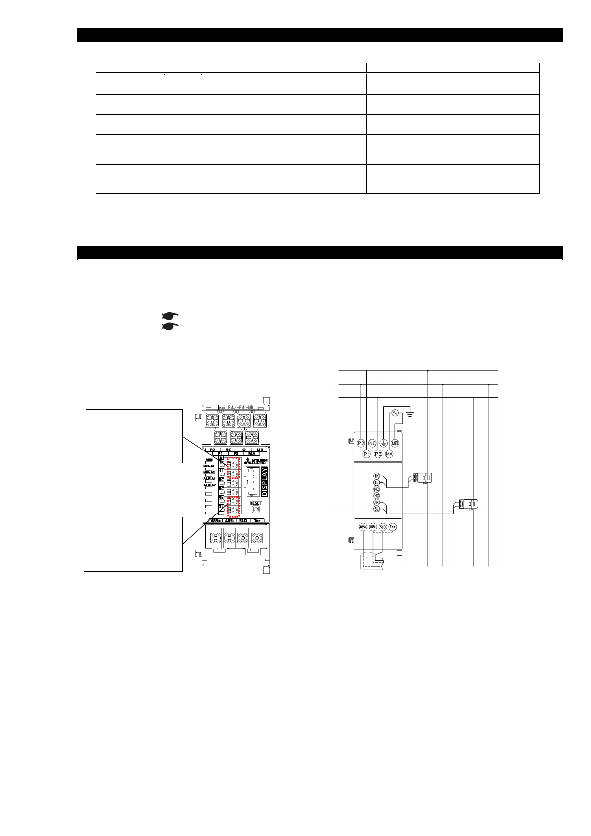
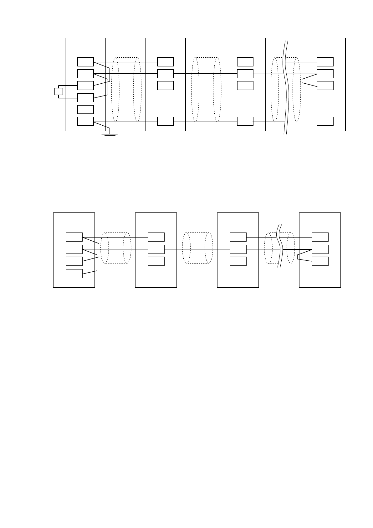
3.1 Name of each part
Connector(small-size display unit)
Connect the display unit.
Reset button
Reset main unit.
LED
Operation mode is
displayed.
( Please reference to 4.2
LED display and function)
Input current
(1K,1L,3K,3L)
Connect the secondary
output of the dedicated
current sensor connected to
the measurement circuit’s
current wire.
※Please setup input current
to 3K,3L
when measuring 2 circuits
by a terminal in 1P2W
(Please reference to the 6.1
Wiring)
Input voltage(P1,P2,P3)
Connect the voltage input wire
for the measuring circuit.
Auxiliary power(MA,MB)
Connect the auxiliary power supply.
MODBUS communication terminal(485+、
485-、SLD、Ter )
485+、485-:MODBUS connect the communication wire.
SLD:Connect to ground (D type ground).
Ter :Connect with “485- “terminal (the unit at end of the link)
Frame GND(FG)
Connect to ground (D type ground).
Connector
(small-size display unit
)
Connect the display unit.
Reset button
Reset main unit.
LED
Operation mode is
displayed.
(Please reference to 4.2 LED
display and function)
Input current
(1K, 1L, 2K, 2L, 3K, 3L)
Connect the secondary
output of the dedicated
current sensor connected to
the measurement circuit’s
current wire.
※Please setup input current
to 3K,3L
when measuring 2 circuits
by a terminal in 1P2W
(Please reference to the 6.1
Wiring)
MODBUS communication terminal(485+,485-,S LD、Ter)
485+、485-:MODBUS connect t he communication wire.
SLD:Connect to ground (D t ype ground).
Ter :Connect with “485- “terminal (the unit at end of the link)
Output terminal(X1,COMX1 )
Connect to pulse/contact
output.
Output terminal
(Y1,COMY1)
Connect to pulse/contact
output.
Input voltage
(P1/P1,P2/P0,P3/P3,NC/P2)
Connect the voltage input wire
for the measuring circuit.
Auxiliary power(MA,MB)
Connect the auxiliary power supply.
Frame GND(FG)
Connect to ground (D type ground).
Connector
(Extension)
Connect to
extension units.
IEC rail fixture
Connector
(Option devices)
Connect to option
Units.
Back view
Right side
Left side
Connection stop
This is used to connect the
extension unit to the Ener
gy
Measuring Unit.
Connection stop
This is used to connect the
option
unit to the Energy
Measuring Unit.
paper.
It is prohibited to reprint or copy all contents of this document in any form without our permission.
The contents of this document will be updated to follow revisions to software and hardware, however under unavoidable
circumstances it may not be synchronized.
(1)EMU4-BM1-MB (2)EMU4-HM1-MB
(3)Back view and side view
5
Page 7
3.2 Indication and function of LEDs
3.3 2 circuits measuring in 1P2W
Circuit A1
The circuit connected to
1K and 1L of SENSOR
A becomes circuit A1.
Circuit A2
The circuit connected to
3K and 3L of SENSOR A
becomes circuit A2.
k l K
L k l K L
Load A1
Load A2
RS-485(MODBUS RTU)
K
1
N
3
Power
supply
side
Load
side
Name
Color
Function
Status
RUN LED
Red
Indicate operating status of this unit.
ON: Normal condition
OFF: Power off or hardware failure (Note 1)
MEA. A1 LED
Red
Indicate measuring status of the circuit
A1.
ON: In the middle of measuring
OFF: Halting measurement
MEA. A2 LED
(Note 2)
Red
Indicate measuring status of the circuit
A2.
ON: In the middle of measuring
OFF: Halting measurement
ALM. A1 LED
Red
Indicate occurrence status of upper/lower
limit alert of the circuit A1.
ON: An error occurs (Note 1)
Blink: Upper/lower limit alert is issued
OFF: No alert
ALM. A2 LED
(Note 2)
Red
Indicate occurrence status of upper/lower
limit alert of the circuit A2.
ON: An error occurs (Note 1)
Blink: Upper/lower limit alert is issued
OFF: No alert
The names and operations of LEDs are as follows.
(Note 1) For details, refer to Chapter 14 "Error codes" of “User’s Manual (Details)”.
(Note 2) Only in the case of single-phase 2-wire system, these indicate the status of the measured circuit of the current sensor in
No.1 side of the circuit A2. (See 3.3)
This unit can measure 2 circuits in the case wiring type 1P2W.
It is a function to measure the 1P2W of 1-N and 3-N branched from 1P3W. (Reference to Figure 3.3.2)
2 circuits measuring can be conducted when current sensor is connected to 1 side (1K, 1L) and 3 side (3K, 3L).
(Reference to Figure 3.3.1 and 3.3.2)
Please reference to 5 chapter about wiring.
Please reference to 6.1 section and EMU4-D65 User’s Manual (Details) when setup for measuring 2 circuits
You can only measure same primary current value in 1 side and 3 side when 2 circuit measuring mode.
Figre3.3.1 Figre3.3.2
6
Page 8
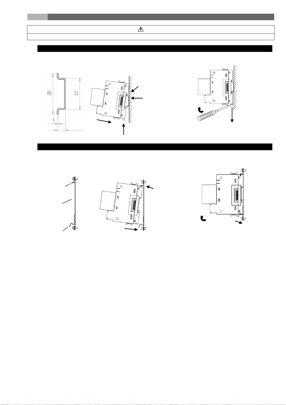
4. Attaching and removing the unit
Any person who is involved in the installation and the wiring of this unit should be fully competent to do this work.
4.1 Mounting on IEC rail
4.2 Mounting on JIS agreement type attachment
•
Applicable IEC rail
(35mm)
•
Mounting
•
Removing
(1) Pull IEC rail fixture downward
(2) Pull the unit
(1) Hold the unit and pull IEC
rail fixture downward
IEC rail
(4) Push the IEC rail
fixture upward
(3) Push in
(2) Catch
7.3 or more
• Mounting
• JIS agreement type
attachment
• Removing
Spring fitting
Attachment
panel
Hook
(2) Hitch 3 chases at
upper part of the
module to the hook
on the attachment
plate
(3) Push the module down and fit in the
spring fitting in chases at the lower
part of the module.
(1) Push the stopper of the IEC rail
above
(1) Push down the
spring fitting
(2) Lift the lower part of
module slowly and
remove in reverse order
of Attaching.
・
Caution
7
Page 9
5. Procedure for wiring
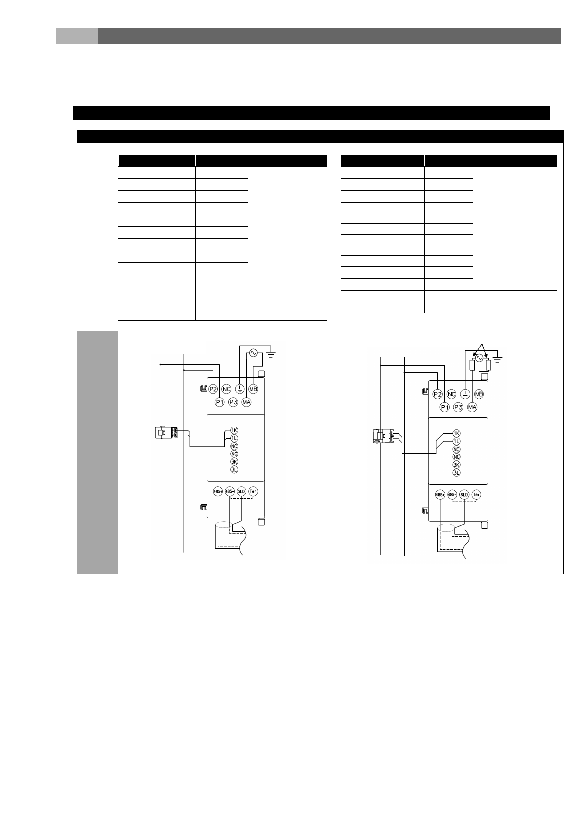
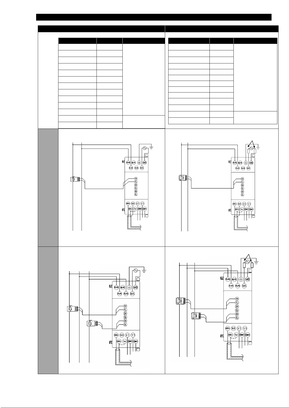
5.1 Wiring for EMU4-BM1-MB
When UL compliance is unnecessary
When UL compliance is necessary
Usable current sensor
Models
Support
remark
EMU-CT50
Connection with
EMU-CT100
EMU-CT250
EMU-CT400
EMU-CT600
EMU-CT5-A
EMU-CT50-A
EMU-CT100-A
EMU-CT250-A
EMU-CT400-A
EMU-CT600-A
EMU2-CT5
Connection with
EMU2-CT5-4W
×*1
*1: EMU2-CT5-4W is only used 3phase-4wire system.
Usable current sensor
Models
Support
remark
EMU-CT50
Connection with
EMU-CT100
EMU-CT250
EMU-CT400
×
EMU-CT600
×
EMU-CT5-A
×
EMU-CT50-A
×
EMU-CT100-A
×
EMU-CT250-A
×
EMU-CT400-A
EMU-CT600-A
EMU2-CT5
Connection with
EMU2-CT5-4W
×*1
Power supply side
Load side
K
L
RS485 (MODBUS RTU)
k
l 1 2
Power supply side
Load side
K
L
RS485 (MODBUS RTU)
k
l
Fuse 0.5A
1
2
Follow the wiring diagram for external connections of this unit.
To use this unit, Base unit (EMU4-BM1-MB、EMU4-HM1-MB、EMU4-LG1-MB) is necessary.
When using this unit, current sensor (EMU-CT***, EMU-CT***-A, EMU2-CT5 or EMU2-CT5-4W) is necessary
(Note) “***” indicates the rated current of the current sensor (50/100/250/400/600).
Please do not use EMU-CT*** type sensor and EMU-CT***-A type sensor with mixture.
1P2W
◯
◯
◯
◯
◯
◯
◯
◯
◯
◯
◯
◯
general wire
dedicated cable
◯
◯
general wire
◯
◯
◯
◯
dedicated cable
*1: EMU2-CT5-4W is only used 3phase-4wire system.
8
Page 10
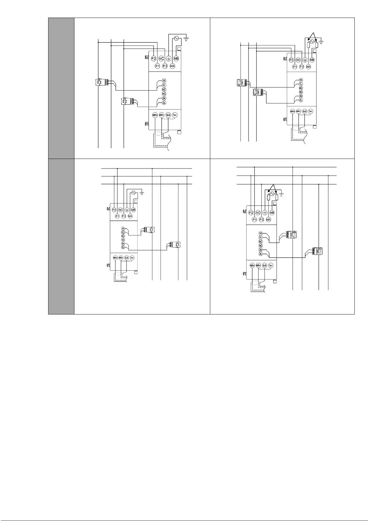
1P3W
Power supply side
Load side
K
L
RS-485 (MODBUS RTU)
k
l
K
L
k
l
1
2
3
1 N 3
Power supply side
Load side
K
L
RS485 (MODBUS RTU)
k
l
K L k
l
Fuse 0.5A
1 2 3
1 N 3
k l K
L
k l K
L
Load A1
Load A2
RS-485(MODBUS RTU)
K
1
N
3
Power
supply
side
Load
side
Load A1
RS-485(MODBUS RTU)
K
L k l
Load A2
K
L
k
l
Fuse 0.5A
1
N
3
Power
supply
side
Load
side
3P3W
1P2W
(2circuit
measurin
g)
9
Page 11
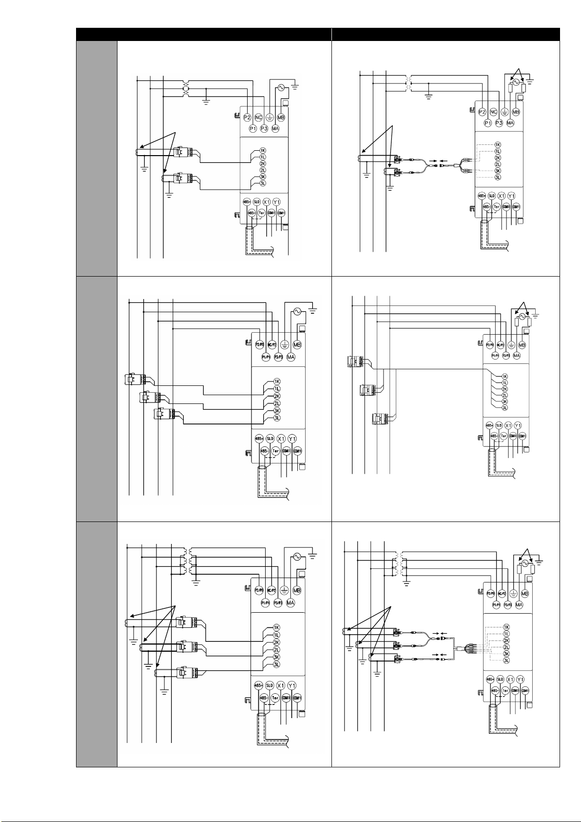
5.2 Wiring for EMU4-HM1-MB
When UL compliance is unnecessary
When UL compliance is necessary
Usable current sensor
Models
Support
remark
EMU-CT50
Connection with
EMU-CT100
EMU-CT250
EMU-CT400
EMU-CT600
EMU-CT5-A
EMU-CT50-A
EMU-CT100-A
EMU-CT250-A
EMU-CT400-A
EMU-CT600-A
EMU2-CT5
Connection with
EMU2-CT5-4W
Usable current sensor
Models
Support
remark
EMU-CT50
Connection with
EMU-CT100
EMU-CT250
EMU-CT400
×
EMU-CT600
×
EMU-CT5-A
×
EMU-CT50-A
×
EMU-CT100-A
×
EMU-CT250-A
×
EMU-CT400-A
EMU-CT600-A
EMU2-CT5
Connection with
EMU2-CT5-4W
Power supply side
Load side
RS-485(MODBUS RTU
)
K
L
k
l
1
2
Power supply side
Load side
RS-485(MODBUS RTU
)
l k K
L
Fuse
0.5A
1
2
Power supply side
Load side
RS-485(MODBUS RTU)
K
L
k
l
K
L
k
l
1 2 3
1 N 3
Power supply side
Load side
RS-485(MODBUS RTU)
l
k
K
L
l
k
K
L
Fuse 0.5A
1 2 3
1
N
3
◯
◯
◯
◯
◯
◯
◯
◯
◯
◯
◯
◯
◯
general wire
dedicated cable
◯
◯
◯
◯
◯
◯
◯
general wire
dedicated cable
1P2W
1P3W
3P3W
10
Page 12
When UL compliance is unnecessary
When UL compliance is necessary
3P3W
Power supply side
Load side
RS-485(MODBUS RTU)
K
L
K
L
l
k
K
L
K
L
l
k
Current transformer
(Secondary current is 5A)
1 2 3
1 N 3
Power supply side
Load side
RS-485(MODBUS
RTU)
K
L
K
L
Current transformer
(Secondary current is 5A)
Fuse 0.5A
1 2 3
1 N 3
Power supply side
Load side
RS
-485(MODBUS RTU)
K
L
l
k
K
L
l
k K L
l
k
1 2 3
N
Power supply side
Load side
RS-485(MODBUS
RTU)
K L l
k
l
k
k
l
K
L
K
L
Fuse 0.5A
1 2 3
N
Power supply side
Load side
RS-485(MODBUS RTU
)
Current transformer
(Secondary current is 5A)
K
L
K
L
K
L
K
L K L
K
L
l k l
k
l
k 1 2 3 N
Current transformer
(Secondary current is 5A)
Load side
RS-485(MODBUS
RTU)
K
L
K
L
K
L
Power supply side
K
L
K
L
K
L
Fuse 0.5A
1 2 3
N
(High
voltage
circuit)
3P4W
3P4W
(Use
with
VT)
11
Page 13
5.3 Precautions for the connection wire
Applicable wire
Tightening
torque
Applicable crimp-type terminal
Power supply terminals,
Stranded wire: AWG26-14
(0.41 - 1.62mm)
0.8 - 1.0 N·m
For M3.5 screw of external
MODBUS communication
terminals
SPEV(SB)-MPC-0.2×1P
equivalent
0.5-0.6 N·m
For M3 screw of external
diameter below 6.1mm
Applicable wire
Tightening
torque
Applicable crimp-type terminal
Power supply terminals,
Stranded wire: AWG26-14
(0.41 - 1.62mm)
0.8 - 1.0N·m
For M3.5 screw of external
MODBUS communication
External input/output terminals
SPEV(SB)-MPC-0.2×1P
0.5-0.6 N·m
For M3 screw of external
Applicable wire
Applicable crimp-type terminal
stranded wire: AWG20-16 (0.5 - 1.3mm2)
single wire: AWG24-17 (0.5 - 1.2mm)
TGV TC-1.25-11T (by NICHIFU) equivalent
• For protection against noise, transmission lines and input/output lines shall not be placed close to or bound
Condition
Distance
High-voltage line 600V or less
300mm or more
Other high-voltage line
600mm or more
burnout or a fire.
together with the power lines and high-voltage lines. Keep distance as below between them. (except for the
terminal block)
Caution
• For the actual usage, connect the FG terminal to ground. (D-type ground: Type 3) Connect it directly to the
ground terminal.
• Do not connect to FG terminal during the insulation resistance test and pressure test. Refer to “User’s manual
(Details)” Chapter 11 “Specifications” for the applying place.
• The current sensors dedicated to this unit EMU-CT400/600 resemble the split current transformer for general
gauges CW-5SL closely in appearance. However, characteristics are completely different. Be sure to connect
the dedicated current sensor. Connecting CW-5SL to this unit directly may cause failure of the device, a
• Maximum voltage of the circuit connected to EMU4-BM1-MB is 260V, EMU4-HM1-MB is 480 (In 3P4W wiring is 277 / 480V). For
the circuit over this voltage, use the transformer. Using the transformer, primary voltage is configurable up to 11000V. Secondary
voltage can be set up to220V.)
• Make sure that before connecting the cable, the orientation of the current sensor is correct for attachment. K to L is the correct
direction. K: power source side, L: load side
• EMU-CT*** and EMU-CT***-A are extendable up to 50m.
• EMU2-CT5 and EMU2-CT5-4W are extendable up to 11 m, using together with an extension cable. To extend the wire further, use
the current transformer CW-5S(L) for split-type instrument in combination, extending the secondary wiring on CW-5S(L) side.
• EMU-CT*** and EMU-CT***-A are used only for low voltage circuit. It cannot be used for a high voltage circuit. EMU2-CT5 and
EMU2-CT5-4W should be used with the secondary side (5A) of transformer transfixed. If they are used for the circuit directly, they
should be used under 200V.
• Do not ground the secondary side of the current sensor.
5.3.1 How to connect wire
<Voltage input terminals, External input/output terminals>
• Use appropriate crimp-type terminal. Applicable crimp-type terminal is shown in the tables below.
• Use electric wires as below, and tighten the terminal screws by the torque as below.
[EMU4-BM1-MB]
Voltage input terminals
[EMU4-HM1-MB]
Voltage input terminals
terminals,
<Current input terminals>
• Stripping length of the used wire in use has to be 10 to 11mm.
• In case using stranded wire, take measures so that the filament should not vary by using a bar terminal or by processing the point
twisted.
• When attaching and detaching cables to/from the terminal, use the push button. Check that the wire is securely inserted.
• Insert a wire to the terminal all the way until it touches the end.
• Use appropriate electric wires as shown below.
(0.13 - 2.0mm2)
Single wire: AWG26-14
(0.13 - 2.0mm2)
Single wire: AWG26-14
equivalent
diameter below 7.1mm
diameter below 7.1mm
diameter below 6.1mm
12
Page 14
5.3.2 Connection of external input / external output
Wire diameter [mm]
Resistivity[Ω/km]
Wiring length[m]
0.5
94
300
0.65
56.8
400
0.9
29.2
750
1.2
16.5
1000
Please connect GND side to
No-voltage a-contact
/ open collector
Voltage of the contact is 5V DC,
and current is 7mA, so use
something appropriate for the
switching condition.
Transmitter
No-voltage a-contact
/ open collector
Voltage of the contact is 5V
DC, and current is 7mA, so
use something appropriate
for the switching condition.
Counter
Relay
In case using external input and/or external output, refer to the following.
External input:For the case of contact input External input: For the case of pulse input
COMX1 when output of
transmitter is open collector pulse.
External output:For the case of contact output External output: For the case of pulse output
• Wiring length of pulse input (Reference value)
The wire length for each wire diameter is below. Please refer to wiring.
※Polyethylene insulating vinyl sheath cable FCPEV wire.
5.3.3 System configuration example of MODBUS communication
●Connection of MODBUS communication terminals:
1. Use the twisted shielded pair cable for transmission lines.(Recommended cable 11. 2 )
2. Connect the termination resistances (120Ω) to both ends of the devices connected the MODBUS transmission line.
Termination resistances of 120Ω can be used by short-circuiting “485-” and “Ter” terminals.
3. Connect to ground by using thick wires to decrease impedance.
4. MODBUS transmission lines shall not be placed close to or bound together with the high-voltage lines.
5. Ground the “SLD” terminal at one end.
13
Page 15
・Wiring for MODBUS module (QJ71MB91, QJ71C24N) and EcoMonitorPlus
Terminal
resistance
MODBUS
Module
(QJ71MB91)
SDA
SDB
RDA
RDB
SG
FG
R
EMU4-BM1-MB
or
EMU4-HM1-MB
485+
485-
Ter
SLD
EMU4-BM1-MB
or
EMU4-HM1-MB
485+
485-
Ter
SLD
EMU4
-BM1
-MB
or
EMU4-HM1-MB
485+
485
-
Ter
SLD
GOT1000
GOT2000
SDA
SDB
RDA
RDB
EMU4-BM1-MB
or
EMU4-HM1-MB
485+
485-
Ter
EMU4-BM1-MB
or
EMU4-HM1-MB
485+
485-
Ter
EMU4-BM1-MB
or
EMU4-HM1-MB
485+
485-
Ter
Note: The terminal resistance of the MODBUS module (QJ71MB91, QJ71C24N) side, please connect "110Ω".
For details, please refer to the instruction manual of the MODBUS module (QJ71MB91, QJ71C24N).
Instruction manual (QJ71MB91): MODBUS Interface Module User's Manual (Manual number: SH(NA)-080578ENG)
Instruction manual (QJ71C24N): Q Corresponding Serial Communication Module User's Manual (Basic) (Manual number:
SH(NA)-080006)
・Wiring for GOT (GOT1000, GOT2000) and EcoMonitorPlus
Note: Please set the terminal resistance of the GOT (GOT1000, GOT2000) "110 Ω".
For the setting procedure, please refer to the connection manual of GOT (GOT1000, GOT2000).
Connection manual (GOT1000): GOT1000 Series Connection Manual (Microcomputer, MODBUS Products, Peripherals)
for GT Works3 (Manual number: SH-080871ENG)
Connection manual (GOT2000): GOT2000 Series Connection Manual (Microcomputers, MODBUS Products,
Peripherals) For GT Works3 Version1 (Manual number: SH-081200ENG)
14
Page 16
6. Setting
6.1 Setting data
Items
EMU4-BM1-MB
EMU4-HM1-MB
Phase wire system
○
○
2 circuits measuring setting
○
○
Primary voltage
○
○
Primary current
○
○
Demand time
○
○
Electric energy converted value
×
○
Cut-off rate of current
○
○
Simple measurement
○
○
External input
×
○
Operating time
○
○
External output
×
○
MODBUS Communication setting
○
○
Setup for logging
○
1
○
1
Setup for upper and lower limit alarm
○
○
Model
Setting value
EMU4-BM1-MB
1P2W、1P3W、3P3W
EMU4-HM1-MB
1P2W、1P3W、3P3W、3P4W
2 circuits measuring
Use, Non-use
Model
Phase wire
system
Use or non-use
of VT
Setting value
EMU4-BM1-MB
1P2W/3P3W
Non-use of VT
[Direct voltage]:110V, 220V
Use of VT
[Primary voltage]:440V, 690V, 1100V, 2200V, 3300V,
1 to 220V(110V)
1P3W
Non-use of VT
(Hold)
[Direct voltage]:110V
To set this unit, dedicated small-size display unit (EMU4-D65) is necessary.
For the setting method, refer to User’s manual (Details) of the display unit.
Items can be setup by model is showed below table.
※
※
*: This items can be setup when using Logging Unit(EMU4-LM).
The data can be setup is showed below. Bold text is default setting value.
Phase wire system
6.1.1
Setup is showed in below table in each unit.
6.1.2
2 circuits measuring setting
Setup is showed in below table in phase wire system is 1P2W.
6.1.3
Primary voltage
Set the rated voltage of the measuring circuit. Please setup the primary voltage of VT when set “Use of VT”.
Primary voltage is set below value by use of VT or not, setup for wiring type and unit.
6600V,11000V, 13200V, 13800V, 15000V, 16500V,
22000V, 24000V, 33000V, 66000V, 77000V,
110000V, SP※
※This setting value can be set [Special primary voltage]
and [Special secondary voltage] when setting SP. Can be
set in the 1V step.
[Special primary voltage]:1 to 110000V(440V)
:
15
Page 17
Model
Phase wire
system
Use or non-use
of VT
Setting value
EMU4-HM1-MB
1P2W/3P3W
Non-use of VT
[Direct voltage]:110V, 220V, 440V
Use of VT
[Primary voltage]:440V, 690V, 1100V, 2200V, 3300V,
6600V,11000V, 13200V, 13800V, 15000V, 16500V,
can set [Special primary voltage] and
[Special secondary voltage]:1 to 220V(110V)
1P3W
Non-use of VT
(Hold)
[Direct voltage]:110V, 220V
3P4W
Non-use of VT
[Direct voltage]:63.5V, 100V, 105V, 110V, 115V, 120V,
250V, 254V, 265V, 277V
Use of VT
[Special primary voltage]:1 to 63500V(440V)
Can be set in the 1V step.
Sensor type
Setting value
Direct sensor
EMU-CT***-A)
[Primary current]:50A, 100A, 250A, 400A, 600A
5A Sensor
[Primary current]:5A, 6A, 7.5A, 8A, 10A, 12A, 15A, 20A, 25A, 30A, 40A, 50A, 60A, 75A, 80A,
[5A sensor special primary current]:5.0 to 30000A(100A)
Caution
EMU-CT*** and EMU-CT***-A are used only for low voltage circuit. It cannot be used for a high voltage circuit.
dangerous
α:1 Single-phase, 2-wire
3 Three-phase, 4-wire
22000V, 24000V, 33000V, 66000V, 77000V,
110000V, SP
※
※This setting
[Special secondary voltage] when setting S P. Can be set
in the 1V step.
[Special primary voltage]:1 to 110000V(440V)
127V, 200V, 220V, 230V, 240V, 242V,
[Special secondary voltage]:1 to 220V(64V)
6.1.4 Primary current
Set the rated current of the measuring circuit. Please select using sensor and setup primary current by sensor type.
Primary current is set below value by the sensor type. Value is common regardless of unit.
(Use of EMU-CT***,
(Use of EMU2-CT5,
EMU2-CT5-4W, EMU-CT5-A)
100A, 120A, 150A, 200A, 250A, 300A, 400A, 500A, 600A, 750A, 800A, 1000A,
1200A, 1250A, 1500A, 1600A, 2000A, 2500A, 3000A, 4000A, 5000A, 6000A,
7500A, 8000A, 10000A, 12000A, 20000A, 25000A, 30000A, SP
※Setup the [5A sensor special primary current] in SP setting. 10A less than, the upper
two digits. 10A or more is possible to set the upper three digits.
EMU2-CT5 and EMU2-CT5-4W should be used with the secondary side (5A) of transformer transfixed. If they are used
for the circuit directly, they should be used under 200V.
If it is connected with a high-voltage circuit by mistake, it may cause a burnout of the device and a fire. It is critically
Supplement ------------------------------------------------------------------------------------------------------------------------------------------
Please setup CT rating of primary side when use EMU2-CT5, EMU2-CT5-4W or EMU-CT5-A.
Full load power is calculated in below equation.
Full load power [kW] =
α × (VT primary voltage) × (CT primary current)
1000
2 Single-phase, 3-wire
√3 Three-phase, 3-wire
*1: VT primary voltage in single-phase 3-wire system is regarded as 110V.
*2: Using direct connection, replace VT primary voltage with direct voltage in calculation above.
*3: In three-phase 4-wire system, replace VT primary voltage or direct voltage with phase voltage in calculation above.
※
16
Page 18
6.1.5 Demand time
Setting item
Setting value
Current demand
time
0sec, 10 sec, 20 sec, 30 sec, 40 sec, 50 sec, 1min, 2 min, 3 min, 4min, 5 min, 6 min, 7 min, 8 min,
9 min, 10 min, 11 min, 12 min, 13 min, 14 min, 15 min, 20 min, 25 min, 30 min
Power demand time
0sec, 10 sec, 20 sec, 30 sec, 40 sec, 50 sec, 1min, 2 min, 3 min, 4min, 5 min, 6 min, 7 min, 8 min,
9 min, 10 min, 11 min, 12 min, 13 min, 14 min, 15 min, 20 min, 25 min, 30 min
Setting item
Setting value
Wh conversion rate
0.001 to 10000(1.000)
Unit
Off, Wh,
2
,
3
, L, kL, sec, min, hour, piece, unit, g, kg, t, ¥, $
Setting item
Setting value
Cut-off current
0.1 to 50.0% (0.5
Setting item
Setting value
Simple measurement
OFF, ON
Setup for power factor
-0.001~1.000~0.000
External input
Setting item
Setting value
Contact input
Reset method
Auto, Hold
Pulse input
Pulse converted
0.001 to 10000(1.000)
Unit
Off, Wh,
2
,
3
, L, kL, sec, min, hour, piece, unit, g, kg, t,
Model
Setting items
Setting value
EMU4-BM1-MB
Counting operating time
OFF, ON
Counting method of operating time
Current input
EMU4-HM1-MB
Counting operating time
OFF, ON
Counting method of operating time
Current input, Contact input
Current demand alarm, electric energy can be setup in each. It is common regardless the unit type.
Electric energy converted value
6.1.6
Setup the converted rate and conversion unit of electric converted value.
You can’t setup in EMU4-BM1-MB. Please setup electric energy conversion rate 1side and 3side in 2 circuits measuring in 1P2W.
Electric energy converted value = Electric energy × Wh conversion rate
kWh, MWh, J, m
m
6.1.7
Cut-off rate of current※
Set the cut-off value when measuring current. Measured current is 0 when measured current is lower than Cut-off current.
Cut-off current = Rated current ×Cut-off rate.
Setup is common regardless of unit type. Please setup cut-off rate of current rate 1side and 3side in 2 circuits measuring.
※The ratio of measured lower current limit (cut-off current) to primary current.
Primary current × cut-off rate = cut-off current
)
6.1.8
Simple measurement
Setup the whether to do simple measurement.
Setup is common regardless of unit type. Please setup power factor 1side and 3side in 2 circuits measuring.
Please reference to
for simple measurement
6.1.9
External input
Setup the measurement target of external input. You can’t setup in EMU4-BM1-MB.
kWh, MWh, J, m
m
¥, $
6.1.10 Operating time
Setup the whether to measure operating time. Setting value is showed below table.
Please setup operating time 1side and 3side in 2 circuits measuring in 1P2W.
Operating time is integration time while current measuring when select Current. Operating time is integration time while Contact
input is ON when Contact input.
17
Page 19

External output
method
Setting item
Setting value
Pulse output
The unit of pulse
Setting range is changed by the value of Full load power.
Total load power(kW)
Setting range
Less than 12
0.001, 0.01, 0.1, 1
12 or more
Less than 120
0.01, 0.1, 1, 10
120 or more
Less than 1200
0.1, 1, 10, 100
1200 or more
Less than 12000
1, 10, 100, 1000
12000 or more
Less than 120000
10, 100, 1000, 10000
120000 or more
100, 1000, 10000, 100000
Alarm output
The object of
1, 2
If the target of external output is 3K, 3L connection side circuit, Set [2].
Setting item
Setting value
MODBUS Address
001 to 255
MODBUS Baud rate
2400, 4800, 9600, 19200, 38400
MODBUS Parity
Non, Even, Odd
MODBUS Sop bit
1, 2
Setting item
Setting value
Logging ID
001~255
Confirmation of logging data
OK、Cancel
6.1.11 External output
Setup the output method of the contact output terminal. Please setup external output in which circuit 1 side circuit or 3 side circuit.
You can’t setup in EMU4-BM1-MB.
output
alarm output
*If the target of external output is 1K, 1L connection side circuit, Set [1].
6.1.12
MODBUS Communication setting
Setup the items for MODBUS communication.Setting values are showed below. This is common regardless of units.
6.1.13 Setup for logging
Setup the items for logging using EMU4-LM. Setting values are showed below. This is common regardless of units.
18
Page 20

6.1.14 Setup for upper and lower limit alarm
Setting item
Setting values
Upper and lower limit alarm existence
ON, OFF
Elements of upper and lower limit alarm
Current demand upper limit, current demand lower limit, line voltage upper
limit, current unbalance rate upper limit, current unbalance rate lower limit
Upper
Current demand upper limit
0~120% of primary current (100% of primary current)
Less than 40A
Step 0.01A
40A ~ 400A
Step 0.1A
400A ~ 4000A
Step 1A
4000A ~
Step 10A
Current demand lower limit
0~120% of primary current (0% of primary current)
Lower than 40A
Step 0.01A
40A ~ 400A
Step 0.1A
400A ~ 4000A
Step 1A
4000A ~
Step 10A
Line voltage upper limit
0~100%×15/11 of primary voltage (110% of primary voltage)
Less than 300V
Step 0.1V
300V ~ 3000V
Step 1V
3000V ~
Step 10V
Line voltage lower limit
0~100%×15/11 of primary voltage(0% of primary voltage)
Less than 300V
Step 0.1V
300V ~ 3000V
Step 1V
3000V ~
Step 10V
Electric power upper limit
-120~0~120% of full load(100% of full load)
Less than 12kW
Step 0. 001kW
12kW ~ 120kW
Step 0.01kW
120kW ~ 1200kW
Step 0.1kW
1200kW ~ 12000kW
Step 1kW
12000kW ~ 120000kW
Step 10kW
120000kW ~
Step 100kW
Electric power lower limit
-120~0~120% of full load(0% of full load)
Less than 12kW
Step 0. 001kW
12kW ~ 120kW
Step 0.01kW
120kW ~ 1200kW
Step 0.1kW
1200kW ~ 12000kW
Step 1kW
12000kW ~ 120000kW
Step 10kW
120000kW
Step 100kW
Power factor upper limit
-0.050, -0.100, …-0.950, 1.000, 0.950, …0.100, 0.050(-0.500)
Power factor lower limit
-0.050, -0.100, …-0.950, 1.000, 0.950, …0.100, 0.050(0.500)
Pulse converted upper limit
1 to 999999(100000)
Current unbalance rate
upper limit
0.01 to 999.99%(30.00%)
Voltage unbalance rate
upper limit
0.01 to 999.99%(3.00%)
Alarm delay time
0sec, 5sec, 10sec, 20sec, 30sec, 40sec, 50sec, 1min, 2min, 3min, 4min,
5min
Alarm reset method
Auto、Hold
Setup the whether to monitor upper and lower limit alarm.
Please refer to 7.2.2 Upper/lower limit monitoring function for more details.
Showed below table. Please setup upper and lower limit alarm of second circuit (3 side circuit) in 2 circuits measuring in 1P2W.
limit, line voltage lower limit, phase voltage upper limit, phase voltage lower
limit, electric power upper limit, electric power lower limit, power factor upper
limit, power factor lower limit, N phase demand current upper limit, N phase
demand current lower limit, pulse converted upper limit, pulse converted lower
and
lower limit
N phase current demand
upper limit
Phase voltage upper limit
Phase voltage lower limit
The minimum step of settable value is varies by primary current.
:
:
:
:
The minimum step of settable value is varies by primary current.
:
:
:
:
The minimum step of settable value is varies by primary voltage.
:
:
:
The minimum step of settable value is varies by primary voltage.
:
:
:
The minimum step of settable value is varies by full load.
:
:
:
:
:
:
The minimum step of settable value is varies by full load.
19
:
:
:
:
:
~
:
Page 21

6.2 Initialization of related item by changing the setup
●
●
●
●
●
●
●
●
●
● ●
○
○
○ ○ ○
○
○ ○
○ ○
○
○ ○
○
○ ○
Demand current alarm(3side)
○ ○
○ ○ ○ ○ ○ ○ ○ ○ ○ □ ○ △
○ ○ ○ ○ ○ ○ ○ ○ ○ □ ○ △
○ ○ ○ ○ ○ ○ ○ ○ ○ □ ○ △ ○
○ ○ ○ ○ ○ ○ ○ ○ ○ □ ○ △
○ ○ ○ ○ ○ ○ ○ ○ ○ □ ○ △
○ ○ ○ ○ ○ ○ ○ ○ ○ □ ○ △ ○
Initialize
Initialize bas ed on the wirinf type.
Initialize when puls e input is turned to be contact area input in the condition that upper/lower lim itof pulse convertion in.
Alarm mask time(3side)
Alarm reset mode(3side)
Logging ID
Additional element4
Contents
□
●
○
Mar k
Logging delete confirmation
Simple measuring s etup
Power factor s etup in simple measuring
Power factor s etup in simple measuring (3side)
Additional element1
Additional element2
Additional element3
Upper and lower limit alarm extence(3side)
Upper and lower limit alarm element(3side)
Upper and lower limit alarm value(3side)
Operating tim e
Operating tim e measuring items
Operating tim e(3side)
Operating tim e measuring items(3side)
Upper and lower limit alarm extence
Upper and lower limit alarm element
Cut-o ff setup
Cut-off s etup(3side)
Demand electric energy alarm (3side)
Modbus address
Modbus baurate
Modbus parity
Modbus stopbit
Upper and lower limit alarm value
Alarm mask time
Alarm reset mode
Electric energy convertion unit (3s ide)
Pulse convertion unit
Pulse convertion
Electric energy convertion(3side)
Electric energy convertion unit
Additional element4
Setup value (initialized)
Wiring type
VT use or non-use
Direct voltage
VT prim ary voltage
VT special primary voltage
Secondary voltage
Current sensor type
Primary current
Simple measuring setup
Power factor setup in simple measuring
Power factor setup in simple(3side)
Additional element1
Additional element2
Additional element3
Upper and lower limit alarm element(3side)
Upper and lower limit alarm value(3side)
External input setup
Contact point reset mode
External input setup
External input target circuit
Pulse output unit
Electric energy convertion
Demand electric energy alarm
Demand current alarm
Current sensor type(3side)
Primary current(3sid e)
Demand electric energy alarm
Demand current alarm
Current sensor type(3phase)
Primary current(3phase)
5A sensor primary special current(3side)
2 circuits measuri ng
2 circuits measuring
Logging delete confirmation
Upper limit alarm extence
Upper limit alarm element
Upper limit alarm value
Alarm mask time
Alarm reset mode
Upper and lower limit alarm extence(3side)
Alarm reset mode(3side)
5A sensor primary special current
Cut-off setup(3side)
Electric energy co nvertion
Electric energy convertion unit
Electric energy convertion(3side)
Electric energy convertion(3side)
Pulse convertion
Pulse convertion unit
Alarm mask time(3sid e)
Demand current alarm(3side)
Modbus address
Modbus baurate
Modbus parity
Operating time
Operating time measuring items
5A sensor prima ry special current
△
Initialize when upper puls e convertion is s etup in upper/lower lim it element.
Setup items
Setup value to be changed
Wiring type
VT use or non-use
Direct voltage
VT primary voltage
VT special prima ry voltage
Secondary voltage
Current sensor type
Modbus stopbit
External input setup
Contact point reset mode
External input setup
External input target circuit
Pulse output unit
5A sensor prima ry special(3side )
Demand electric energy(3side)
Operating time(3side)
Operating time measuring items(3side)
Cut-o ff setup
Primary current
Logging ID
Setup value and measured data is initialized after change the setting value according to table 6.2.1 and 6.2.2.
Please setup again.
Table 6.2.1 List of initialization when changing setup value (setup data)
20
Page 22

Table 6.2.2 List of initialization when changing setup value (Measured data and operating data)
Electric energy(consumption)
Regenerate electric energy
Reactive electric energy
Periodic electric energy
○
Electiric energy convertion
Electiric energy convertion (3phase)
Pulse count
○
Pulse convertion
○
Operating tim e
○
Electric energy (consumption) (3phase)
Regenerate electric energy (3phase)
Periodic electric energy (3phase)
CO2 convertion
Operating tim e (3phase)
○
Line voltage (all phas es)
○
○ ○ ○ ○ ○ ○
Line voltage (1-2)
○
○ ○ ○ ○ ○ ○
Line voltage (2-3)
○ ○ ○ ○ ○ ○ ○
Phase voltage (All phases )
○
○ ○ ○ ○ ○ ○
Powr factor (All phases)
○
○ ○ ○ ○ ○ ○ ○ ○ ○
Powr factor (1phase)
○
○ ○ ○ ○ ○ ○ ○ ○ ○
Powr factor (3phase)
○
○ ○ ○ ○ ○ ○ ○ ○ ○
Demand current (All phas es)
○
○ ○ ○ ○ ○
Demand current (1 phase)
○
○ ○ ○ ○ ○
Demand current (3 phase)
○ ○ ○ ○ ○ ○
Demand electric power (All phas es)
○
○ ○ ○ ○ ○ ○ ○ ○ ○ ○
Demand electric power (1 phase)
○
○ ○ ○ ○ ○ ○ ○ ○ ○ ○
Demand electric power (3 phase)
○
○ ○ ○ ○ ○ ○ ○ ○ ○ ○
Current unbalance rate
○
○ ○ ○ ○
Voltage unbalance rate
○
○ ○ ○ ○ ○ ○
Line voltage (all phas es)
○ ○ ○ ○ ○ ○ ○
Line voltage (1-2)
○ ○ ○ ○ ○ ○ ○
Line voltage (2-3)
○ ○ ○ ○ ○ ○ ○
Phase voltage
○
○ ○ ○ ○ ○ ○
Powr factor (All phases)
○ ○ ○ ○ ○ ○ ○ ○ ○ ○
Powr factor (1phase)
○ ○ ○ ○ ○ ○ ○ ○ ○ ○
Powr factor (3phase)
○ ○ ○ ○ ○ ○ ○ ○ ○ ○
Demand current (All phas es)
○ ○ ○ ○ ○ ○
Demand current (1 phase)
○ ○ ○ ○ ○ ○
Demand current (3 phase)
○ ○ ○ ○ ○ ○
Demand electric power (All phas es)
○
○ ○ ○ ○ ○ ○ ○ ○ ○ ○
Demand electric power (1 phase)
○
○ ○ ○ ○ ○ ○ ○ ○ ○ ○
Demand electric power (3 phase)
○ ○ ○ ○ ○ ○ ○ ○ ○ ○ ○
Setup items
Setup value to be changed
Wiring type
VT use or non-use
Direct voltage
VT primary voltage
VT special prima ry voltage
Secondary voltage
Current sensor type
Primary current
Demand electric energy(3side)
Demand current alarm(3side)
Modbus address
Modbus baurate
Modbus parity
Modbus stopbit
5A sensor prima ry special current
Demand electric energy alarm
Demand current alarm
Current sensor type(3side)
Primary current(3sid e)
5A sensor prima ry special(3side )
Electric energy convertion unit
Electric energy convertion(3side)
Electric energy convertion(3side)
Pulse convertion
Pulse convertion unit
Operating time
External input setup
Contact point reset mode
External input setup
External input target circuit
Pulse output unit
Electric energy co nvertion
Upper and lower limit alarm element
Upper and lower limit alarm value
Alarm mask time
Alarm reset mode
Upper limit alarm extence(3side)
Upper limit alarm element(3side)
Operating time measuring items
Operating time(3side)
Operating time measuring items(3side)
Cut-o ff setup
Cut-off setup(3side)
Upper and lower limit alarm extence
2 circuits measuri ng
○
Initialize.■Initialize (Not initialize in 1P2W).
Measured value (initialized)
Integral value
Max
Min
Mark
Contents
Power factor setup in simple measuring
Power factor setup in simple measuring(3side)
Additional element1
Additional element2
Additional element3
Additional element4
Upper limit alarm value(3side)
Alarm mask time(3sid e)
Alarm reset mode(3side)
Logging ID
Logging delete confirmation
Simple measuring setup
21
Page 23

7. Operation
7.1 Measurement
Model
Display
mode
1P2W
1P2W
1P2W
Electric energy
Present value
● ● ● ● ● ● ● ● ●
Converted electric
energy
Periodic electric
energy
○ ○ ○
○ ○ ○ ○ ○ ○ ● ● ●
Regenerated electric
energy
Pulse count
Present value
Pulse converted value
Present value
Current
1,2,3,N,Total
1
1,2,3,N
1
Max, Min
1-2,2-3,3-1,1-N,
2-N,3-N,Total※2
Max, Min
Electric power
Present value
Electric power
demand
Present value
Max, Min
Reactive power
Present value
○ ○ ○ ○ ○ ○ ● ● ●
─ ─ ─ ─ ─
○
7
─ ─ ─
Present value
Max, Min
○ ○ ○ ○ ○ ○ ● ● ●
Harmonics total
RMS/Distortion ratio
Harmonics total
RMS/Distortion ratio
Harmonics current※9
RMS/Distortion ratio
Harmonics voltage※9
RMS/Distortion ratio
1-2,2-3,
1-N,2-N,3-N※4
Reactive energy
Present value
○ ― ○ ○ ― ○ ─ ─ ─
Current unbalance
rate
Present value
Max
Voltage unbalance
rate
Present value
Max
●
8
●
8
●
8
●
8
●
8
●
8
●
8
●
8
●
8
Error
─
● ● ● ● ● ● ● ● ●
Measurement elements are showed below table in each unit.
In the case displaying in Display unit.
● … Measured elements ○…Elements displayed when only setup and selected ─ … Not displayed elements
EMU4-BM1-MB EMU4-HM1-MB
Wh+A+4 elements Wh+A+4 elements Harmonics
Wiring type
Present value
Present value
Operating time Present value
Present value
Current demand
Voltage
Apparent power Present value
Power factor
Frequency Present value
※
※
1P3W
/3P3W
/3P4W
1 circuit
measuring
2 circuits
measuring
1 circuit
measuring
2 circuits
measuring
1P3W
/3P3W
1 circuit
measuring
2 circuits
measuring
─ ─ ─ ○ ○ ○ ● ● ●
─ ─ ─
● ● ●
○ ○ ○ ○ ○ ○ ● ● ●
─ ─ ─ ○ ○ ○ ● ● ●
● ● ● ● ● ● ● ● ●
○ ○ ○ ○ ○ ○ ● ● ●
○ ○ ○ ○ ○ ○ ● ● ●
※
○ ○ ○ ○ ○ ○ ● ● ●
1P3W
/3P3W
/3P4W
current
voltage
1,2,3,N※3
1-2,2-3,3-1,
1-N,2-N,3-N
1,2,3,N※3
─ ─ ─ ○ ○ ○
※4
─ ─ ─ ○ ○ ○
─ ─ ─ ─ ─ ─
─ ─ ─ ─ ─ ─
※
6
○
○
※
6
○
○
Time Present value
※1 2 and 3 phases is not displayed in wiring setting 1P2W. N phase is only displayed in 3P4W setting.
※2 Between 2 and 3 , 3 and 1 is not displayed in setting 1P2W1-N . Between 2 and N, 3 and N is displayed in 3P4W setting.
※3 If wiring setting is 1P2W, 3 phase is not displayed. 2 phase is only displayed in setting 3P4W.
※4 If wiring setting is 1P2W, between 2 and 3 is not displayed. Between 1 and N, 2 and N, 3 and N is only displayed.
※5 Either effective value and content rate ,distortion by the setting elements of HA and HV.
※6 Current unbalance rate, voltage unbalance rate is displayed 0% in 1P2W setting.
※7 Apparent power is only measured in 3P4W setting
※8 Present time is only displayed when connected EMU4-LM.
※9 3rd, 5th, 7th, 9th, 11th, 13th are displayed.
※
※
6
○
※
6
○
※
※
※
○
※
○
※
6
○
6
○
※
6
○ ─ ─ ○
※
6
○ ─ ─ ○
※
※
※
○
※
○
※
○
※
○
※
5
○
5
○
5
○
5
○
※
5
○
※
5
○
※
5
○
※
5
○
※
※
5
※
5
※
5
※
5
※
22
Page 24

In the case monitoring by MODBUS communication and CC-Link communication
Model
EMU4-BM1-MB
EMU4-HM1-MB
Electric energy
Present value
● ● ● ● ●
●
Electric energy(Extended)
Present value
● ● ● ● ●
●
Converted electric
energy
Periodic electric
energy
Operating time
Present value
● ● ● ● ●
●
Regenerated electric
energy
● ● ●
Pulse count
Present value
Pulse converted value
Present value
Current
1,2,3,N, Total
● ● ● ● ●
●
1,2,3,N ● ● ● ● ● ●
Max, Min ─ ─ ─ ─ ─ ─
1-2,2-3,3-1,1-N,
2-N,3-N, Total
Max, Min ─ ─ ─ ─ ─ ─
Electric power
Present value
● ● ● ● ●
●
Electric power
demand
Present value
● ● ● ● ●
●
Max, Min ─ ─ ─ ─ ─ ─
Reactive power
Present value
● ● ● ● ●
●
Reactive power
(Extended)
● ● ●
Apparent power
Present value
─ ─ ─ ─ ─
●
1
Present value
● ● ● ● ●
●
Max, Min ─ ─ ─ ─ ─ ─
Frequency
Present value
● ● ● ● ●
●
Harmonics total current
RMS/Distortion ratio
Harmonics total voltage
RMS/Distortion ratio
1-2,2-3,3-1,
1-N,2-N,3-N
Harmonics current
RMS/Distortion ratio
Harmonics voltage
RMS/Distortion ratio
1-2,2-3,
1-N,2-N,3-N
Reactive energy
Present value
● ● ● ● ●
●
Current unbalance
Rate*2
Present value
─ ─ ● ─ ─
●
Max, ─ ─ ─ ─ ─ ─
Voltage unbalance
rate*2
Present value
─ ─ ● ─ ─
●
Max ─ ─ ─ ─ ─ ─
Time
Present value
─ ─ ─ ─ ─
─
Error ─ ● ● ● ● ●
●
● … Data can monitoring ─ … Data cannot monitoring
Current demand
Voltage
Power factor
Wiring
type
1 circuit
measuring
1P2W
2 circuits
measuring
1P3W
/3P3W
measuring
1 circuit
1P2W
measuring
2 circuits
1P3W
/3P3W
/3P4W
Present value ─ ─ ─ ● ● ●
Present value ─ ─ ─ ● ● ●
Present value
● ● ●
─ ─ ─ ● ● ●
● ● ● ● ● ●
Present value
● ● ●
※
1,2,3,N ─ ─ ─ ● ● ●
─ ─ ─ ● ● ●
1,2,3,N ─ ─ ─ ● ● ●
─ ─ ─ ● ● ●
※1 Apparent power is only measured in 3P4W wiring.
※2 These values can be monitored only CC-Link Communication.
23
Page 25

In the case logging using EMU4-LM.
Model
EMU4-BM1-MB
EMU4-HM1-MB
1P2W
1P3W
3P3W
1P2W
1P3W
3P3W
3P4W
Current
Average
● ● ● ● ● ● ●
Phase 1
● ● ● ● ● ● ●
Phase 2
─ ● ● ─ ● ● ●
Phase 3
●*1 ● ●
●*1 ● ●
●
Phase N
─ ─ ─ ─ ─ ─ ●
Current
Phase 1
● ● ● ● ● ● ●
Phase 2
─ ● ● ─ ● ● ●
Phase 3
●*1 ● ●
●*1 ● ●
●
Phase N
─ ─ ─ ─ ─ ─ ●
Voltage
Phase 1-N
─ ─ ─ ─ ─ ─ ●
Phase 2-N
─ ─ ─ ─ ─ ─ ●
Phase 3-N
─ ─ ─ ─ ─ ─ ●
Average
● ● ● ● ● ● ●
1-2 ● ● ● ● ● ● ● 2-3
●*1 ● ●
●*1 ● ●
●
3-1 ─ ● ● ─ ● ●
●
Electric
[1]
※2
● ● ● ● ● ● ●
[2]
※2
● ― ― ● ― ― ―
[1]
※2
● ● ● ● ● ● ●
[2]
※2
● ― ― ● ― ― ―
power
[1]
※2
● ● ● ● ● ● ●
[2]
※2
● ― ― ● ― ― ―
Apparent power
─ ─ ─ ─ ─ ─ ●
[1]
● ● ● ● ● ● ●
[2]
※2
● ― ― ● ― ― ―
Frequency
● ● ● ● ● ● ●
Current unbalance rate
─ ● ● ─ ● ● ●
Voltage unbalance rate
─ ● ● ─ ● ● ●
Harmonics
RMS
Average
Phase 1
─ ─ ─ ● ● ● ●
Phase 2
─ ─ ─ ─ ─ ─ ●
Phase 3
─ ─ ─
●*1 ● ●
●
Phase N
─ ─ ─ ─ ─ ─ ●
Distortion
Average
Phase 1
─ ─ ─ ● ● ● ●
Phase 2
─ ─ ─ ─ ─ ─ ●
Phase 3
─ ─ ─
●*1 ● ●
●
Phase N
─ ─ ─ ─ ─ ─ ●
Harmonics
RMS Average
Phase 1-N
─ ─ ─ ● ● ● ●
Phase 2-N
─ ─ ─ ─ ─ ─ ●
Phase 3-N
─ ─ ─
●*1 ● ●
●
Phase N
─ ─ ─ ─ ─ ─ ●
1-2 ─ ─ ─ ● ● ●
─
2-3 ─ ─ ─ ●*1 ● ●
─
Distortion
Average
Phase 1-N
─ ─ ─ ─ ─ ─ ●
Phase 2-N
─ ─ ─ ─ ─ ─ ●
Phase 3-N
─ ─ ─ ─ ─ ─ ●
1-2 ─ ─ ─ ● ● ● ─ 2-3 ─ ─ ─ ●*1 ● ●
─
Electric
Consump
tion
[1]*2 ● ● ● ● ● ● ● [2]*2 ● ─ ─ ● ─ ─
─
Regener
ated
[1]*2 ● ● ● ● ● ●
●
[2]*2 ● ─ ─ ● ─ ─
─
Consumption(expanded)
─ ─ ─ ─ ─ ─ ─
Regenerated(expanded)
─ ─ ─ ─ ─ ─ ─
Reactive
Consumption delay
● ● ● ● ● ● ●
Consumption delay(expanded)
─ ─ ─ ─ ─ ─ ─
Electric energy conversion
─ ─ ─ ─ ─ ─ ─
Operating time
─ ─ ─ ─ ─ ─ ─
Periodic electric energy
─ ─ ─ ● ● ● ●
Pulse count
─ ─ ─ ● ● ● ●
Pulse conversion
─ ─ ─ ● ● ● ●
● … Data can logging ─ … Data cannot logging
Elements
demand
power
Electric power
demand
Reactive
Power factor
total
current
total
voltage
energy
ratio
ratio
※2
Basic
th
3~13
th
3~13
Basic
th
3~13
3~13th
energy
*1: Shows second circuit (3 side circuit) when setting 2 circuits measuring in 1P2W.
*2: [1] shows first circuit when setting 2 circuits measuring in 1P2W. It is displayed when not setting 2 circuits measuring
or 1P3W, 3P3W, 3P4W.[2] shows second circuit (3 side) when setting 2 circuits measuring in 1P2W.
24
Page 26

The details of measuerment items showed below table.
Item
Details
The sign of measured value is showed below figure.
Calculated depending on the phase-wire system.
Phase-wire system
Calculating formula
Single-phase 2-wire
phase 1 current
Single-phase 3-wire
Three-phase 3-wire
(phase 1 current + phase 3 current) / 2
Three-phase 4-wire
(phase 1 current + phase 2 current + phase 3 current) / 3
Calculated depending on the phase-wire system.
Phase-wire system
Calculating formula
Single-phase 2-wire
voltage V12
Single-phase 3-wire
Three-phase 3-wire
(voltage V12+ voltageV23) / 2
Three-phase 4-wire
(voltage V12 + voltage V23+ voltage V31) / 3
Calculated below equation.
Electric energy converted value:0.000~10000(Initial value:1.000)
Measuring the time during contact input is ON or measuring current.
Measurement range
Unit
0~999999
Time [hour]
Measure the input pulse. Measure the output pulse of equipment by connecting it.
Measurement range
Unit
0~999999
Pulse
Calculated below equation.
Pulse converted value:0.000~10000(Initial value:1.000)
90°
0°
270°
180°
+
-
Consumption
delay
Regeration
progress
Regeration
delay
+
-
Consumption
progress
Electric power
Reactive power
Power factor
RMS current value (Average)
RMS voltage value (Average)
Electric energy conversion
Electric energy×Electric energy converted value
※
Operating time
Periodic electric energy Measuring the electric energy (consumption) during contact input is ON.
Pulse count
Pulse conversion
Pulse count ×Pulse converted value
※
25
Page 27

7.2 Upper/lower limit monitoring function
Monitoring items
Display or not in each unit
EMU4-BM1-MB
EMU4-HM1-MB
Current demand upper limit alarm
●
●
Current demand lower limit alarm
●
●
Line voltage upper limit alarm
●
●
Line voltage lower limit alarm
●
●
Phase voltage upper limit alarm
―
●
1
Phase voltage lower limit alarm
―
●
1
Electric energy demand upper limit alarm
●
●
Electric energy demand lower limit alarm
●
●
Power factor upper limit alarm
●
●
Power factor lower limit alarm
●
●
Phase N current demand upper limit alarm
―
●
1
Pulse conversion upper limit alarm
―
●
Current unbalance rate upper limit alarm
●
●
Voltage unbalance rate upper limit alarm
●
●
7.2.1 About monitoring elements
Monitoring elements in each unit are showed in below table.
● … Can monitor data ─ … Can’t monitoring data
※1 Can only monitor only when wiring type is 3P4W.
※
※
※
26
Page 28

7.2.2
Voltage unbalance rate
factor,
Reset method
Alarm recovery operation
Reset the alarm automatically if the measured value goes below the
upper limit or goes over the lower limit.
The alarm is held after the measured value goes below the upper limit or
goes over the lower limit. Alarm is cleared by alarm reset.
Alarm item
Alarm reset
method
Alarm status
Alarm occurrence / recovery condition
Measured value > configured upper limit
(Alarm delay time is available)
Measured value < configured lower limit
(Alarm delay time is available)
Recovery
Measured value > configured lower limit
Measured value > configured upper limit
(Alarm delay time is available)
Measured value < configured upper limit
Alarm reset
Measured value < configured lower limit
(Alarm delay time is available)
Retention
Measured value ≥ configured lower limit
Measured value > configured lower limit
Alarm reset
Recovery
Measured value < configured upper limit
Recovery
Measured value < configured upper limit
How to use upper/lower limit alarm function
This device can set the upper/lower limit alarm value for each measured value individually.
< Monitoring items >
Upper limit alarm items Current demand, Line voltage, Phase voltage, Electric power demand, Power
factor, N phase current demand, Pulse converted, Current unbalance rate,
Lower limit alarm items Current demand, Line voltage, Phase voltage, Electric power demand, Power
< Alarm setting >
・Upper limit value Set the upper limit of measured value. For setting value and setting range,
6.1.12 Upper and lower alarm setting
・Lower limit value Set the lower limit of measured value. For setting value and setting range,
6.1.12 Upper and lower alarm setting
・Alarm delay time Set the value in case you want to remove the inrush current of the load, etc. from the objects of
monitoring. Alarm does not occur when the measured value goes below the upper limit or goes over the
lower limit within the configured time. For setting value and setting range,
6.1.12 Upper and lower alarm setting
・Alarm reset method Alarm recovery operation is different according to the alarm reset method.
Auto-reset (Auto)
Self-retention (Hold)
For setting alarm reset operation 6.1.12 Upper and lower alarm setting. Please reference to display unit instruction
manual (detail).
< Alarm occurrence / recovery condition >
Occurrence
Recovery Measured value < configured upper limit
Occurrence
Occurrence
Retention Measured value ≤ configured upper limit
Recovery
Occurrence
Recovery
Occurrence Measured value ≥ configured upper limit
Occurrence Measured value ≥ configured upper limit
Current demand
Line voltage
Phase voltage
Electric power demand
Power factor
Phase N current demand
Current unbalance rate
Voltage unbalance rate
Pulse conversion
Auto-reset
(Auto)
Self-retention
(Hold)
Auto-reset
(Auto)
Self-retention
(Hold)
Upper limit
alarm
Lower limit
alarm
Upper limit
monitoring
Lower limit
monitoring
Upper limit
monitoring
Lower limit
monitoring
Caution: Since the measured value of pulse count value is an integrated value, it does not decrease.
When an alarm occurs, it is necessary to satisfy the recovery condition by one of the following methods.
・Reset Pulse count
・Preset Pulse count less than setting value of upper limit alarm
・Setup upper limit alarm more than pulse count
AND
AND
27
Page 29

(1) Upper limit alarm
Upper alarm
work
Non-occurence Non-occurence
Alarm
status
Measuring after turn ON.
Alarm delay time Alarm delay time
Alarm does not work becase
of not meeting alarm
conditions in m ask time.
Upper
alarm value
Upper limit
alarm
Non-occurence Non-occurence
Alarm
status
Measuring after turn ON.
Alarm
hold
Alarm delay time
Alarm delay time
Alarm does not work becase
of not meeting alarm
conditions in m ask time.
Upper
alarm value
Demand
alarm
release
Demand
alarm
release
Alarm status does not turn to nonoccurance and contact output turn
to OFF because of excess upper
alarm.
Lower limit
alarm
Non-occurence Non-occurence
Alarm
status
Measuring after turn ON
.
Alarm delay time Alarm delay time
Alarm does not work becase
of not meeting alarm
conditions in mask time.
Lower
alarm value
Lower limit
alarm
Non-occurence Non-occurence
Alarm
status
Measuring after turn ON.
Alarm
hold
Alarm delay time Alarm delay time
Alarm does not work becase
of not meeting alarm
conditions in m ask time.
Lower
alarm value
Demand
alarm
release
Demand
alarm
release
Alarm status does not turn to nonoccurance and contact output turn
to OFF because of below lower
alarm.
Alarm reset method = Auto Alarm reset method = Hold
(2) Lower limit alarm
Alarm reset method = Auto Alarm reset method = Hold
28
Page 30

7.3 Simple measurement
Wh+A+4 elements
Wh+A+4 elements
Harmonics
1P2W
1P2W
1P2W
● ● ● ● ● ● ● ● ●
─ ─ ─ ○ ○ ○ ● ● ●
─ ─ ─ ○ ○ ○ ● ● ●
○ ○ ○ ○ ○ ○ ● ● ●
Pulse count
Present value
Pulse converted value
Present value
1,2,3,N,Total
1
1,2,3,N
1
Max,Min
Electric power
Present value
Present value
Max,Min
○ ○ ○ ○ ○ ○ ● ● ●
─ ─ ─ ─ ─
○
3
─ ─ ─
○ ― ○ ○ ― ○ ─ ─ ─
Present value
Present value
●
4
●
4
●
4
●
4
●
4
●
4
●
4
●
4
●
4
● ● ● ● ● ● ● ● ●
Model
1P2W
1P2W
Electric energy
Present value
● ● ● ● ●
●
Converted electric
energy
Periodic electric
energy
Operating time
Present value
● ● ● ● ●
●
Pulse count
Present value
Pulse converted
value
Current
1,2,3,N, total
1,2,3,N
Max, Min
Electric power
Present value
Electric power
demand
Present value
Max, Min
Reactive power
Present value
● ● ● ● ●
●
Apparent power
Present value
─ ─ ─ ─ ─
─
Reactive energy
Present value
● ― ● ─ ─
─
Current unbalance
rate
Present value
Max
Time
Present value
― ― ― ― ―
―
Error ─ ● ● ● ● ●
●
This unit is equipped monitoring function without input voltage.
Each measurement elements calculated by the voltage and power factor and input current.
Measurement resolution is not guarantee.
7.3.1 Measurement elements
The elements can measure are showed below table.
In the case displaying in Display unit.
EMU4-BM1-MB EMU4-HM1-MB
1 circuit
measuring
Electric energy
Converted electric energy
Periodic electric energy
Operating time
Present value
Present value
Present value
Present value
─ ─ ─ ○ ○ ○ ● ● ●
Current
Current demand
Electric power demand
Reactive power
Apparent power
Reactive energy
Current unbalance rate
Time
Error
※1 2 and 3 phases is not displayed in wiring setting 1P2W. N phase is only displayed in 3P4W setting.
※2 Current unbalance rate, voltage unbalance rate is displayed 0% in 1P2W setting.
※3 Apparent power is only measured in 3P4W setting.
※4 Present time is only displayed when connected EMU4-LM.
Present value
Present value
Present value
Present value
─
In the case monitoring by MODBUS communication.
※
※
● ● ● ● ● ● ● ● ●
○ ○ ○ ○ ○ ○ ● ● ●
※
2
○
※
2 circuits
measuring
○
1P3W
/3P3W
※
2
○
※
EMU4-BM1-MB EMU4-HM1-MB
※
1 circuit
measuring
※
2
○
※
2 circuits
measuring
○
1P3W
/3P3W
/3P4W
※
※
2
○ ─ ─ ○
※
※
1 circuit
measuring
※
2 circuits
measuring
※
1P3W
/3P3W
/3P4W
※
Wiring
type
Present value ─ ─ ─ ● ● ●
Present value ─ ─ ─ ● ● ●
Present value
Current demand
1 circuit
measuring
─ ─ ─ ● ● ●
● ● ● ● ● ●
● ● ● ● ● ●
● ● ● ─ ─ ●
2 circuits
measuring
1P3W
/3P3W
1 circuit
measuring
2 circuits
measuring
1P3W
/3P3W
/3P4W
29
Page 31

In the case logging using EMU4-LM (1/2).
Model
EMU4-BM1-MB
EMU4-HM1-MB
1P2W
1P3W
3P3W
1P2W
1P3W
3P3W
3P4W
Current
Average
● ● ● ● ● ● ●
Phase 1
● ● ● ● ● ● ●
Phase 2
─ ● ● ─ ● ● ●
Phase 3
●*1 ● ●
●*1 ● ●
●
Phase N
─ ─ ─ ─ ─ ─ ●
Current
Phase 1
● ● ● ● ● ● ●
Phase 2
─ ● ● ─ ● ● ●
Phase 3
●*1 ● ●
●*1 ● ●
●
Phase N
─ ─ ─ ─ ─ ─ ●
Voltage
Phase 1-N
*3
*3
*3
*3
*3
*3
*3
Phase 2-N
*3
*3
*3
*3
*3
*3
*3
Phase 3-N
*3
*3
*3
*3
*3
*3
*3
Average
*3
*3
*3
*3
*3
*3
*3
1-2
*3
*3
*3
*3
*3
*3
*3
2-3
*3
*3
*3
*3
*3
*3
*3
3-1
*3
*3
*3
*3
*3
*3
*3
[1]
※2
● ● ● ● ● ● ●
[2]
※2
● ― ― ● ― ― ―
[1]
※2
● ● ● ● ● ● ●
[2]
※2
● ― ― ● ― ― ―
power
[1]
※2
● ● ● ● ● ● ●
[2]
※2
● ― ― ● ― ― ―
Apparent power
─ ─ ─ ─ ─ ─ ●
[1]
*3
*3
*3
*3
*3
*3
[2]
※2
*3
*3
*3
*3
*3
*3
*3
Frequency
*3
*3
*3
*3
*3
*3
*3
Current unbalance rate
─ ● ● ─ ● ● ●
Voltage unbalance rate
*3
*3
*3
*3
*3
*3
*3
● … Data can logging
─ … Data cannot logging
△ … Fixed Data
Elements
demand
Electric
power
Electric power
demand
Reactive
△
△
△
△
△
△
△
△
△
△
△
△
△
△
△
△
△
△
△
△
△
△
△
△
△
△
△
△
△
△
△
△
△
△
△
△
△
△
△
△
△
△
△
△
△
△
△
△
△
Power factor
※2
*3
△
△
△
△
△
△
△
△
△
△
△
△
△
△
△
△
△
△
△
△
△
△
△
△
△
△
△
△
30
Page 32

In the case logging using EMU4-LM (2/2).
Model
EMU4-BM1-MB
EMU4-HM1-MB
1P2W
1P3W
3P3W
1P2W
1P3W
3P3W
3P4W
Harmonics
RMS
Average
Phase 1
*3
*3
*3
*3
*3
*3
*3
Phase 2
*3
*3
*3
*3
*3
*3
*3
Phase 3
*3
*3
*3
*3
*3
*3
*3
Phase N
*3
*3
*3
*3
*3
*3
*3
Distortion
Average
Phase 1
*3
*3
*3
*3
*3
*3
*3
Phase 2
*3
*3
*3
*3
*3
*3
*3
Phase 3
*3
*3
*3
*3
*3
*3
*3
Phase N
*3
*3
*3
*3
*3
*3
*3
Harmonics
RMS Average
Phase 1-N
*3
*3
*3
*3
*3
*3
*3
Phase 2-N
*3
*3
*3
*3
*3
*3
*3
Phase 3-N
*3
*3
*3
*3
*3
*3
*3
Phase N
*3
*3
*3
*3
*3
*3
*3
1-2
*3
*3
*3
*3
*3
*3
*3
2-3
*3
*3
*3
*3
*3
*3
*3
Distortion
Average
Phase 1-N
*3
*3
*3
*3
*3
*3
*3
Phase 2-N
*3
*3
*3
*3
*3
*3
*3
Phase 3-N
*3
*3
*3
*3
*3
*3
*3
1-2
*3
*3
*3
*3
*3
*3
*3
2-3
*3
*3
*3
*3
*3
*3
*3
Electric
Consump
tion
[1]*2 ● ● ● ● ● ● ● [2]*2 ● ─ ─ ● ─ ─
─
Regener
[1]*2
*3
*3
*3
*3
*3
*3
*3
[2]*2
*3
*3
*3
*3
*3
*3
*3
Consumption(expanded)
─ ─ ─ ─ ─ ─ ─
Regenerated(expanded)
─ ─ ─ ─ ─ ─ ─
Reactive
Consumption delay
● ● ● ● ● ● ●
Consumption delay(expanded)
─ ─ ─ ─ ─ ─ ─
Electric energy conversion
─ ─ ─ ─ ─ ─ ─
Operating time
─ ─ ─ ─ ─ ─ ─
Periodic electric energy
─ ─ ─ ● ● ● ●
Pulse count
─ ─ ─ ● ● ● ●
Pulse conversion
─ ─ ─ ● ● ● ●
Behaviors of this unit
Current
Current is 0A when input current is lower than cut-off setup value.
Power
Apparent power
Indicate “0W”, “0var” or “0VA” if indicated current values of all phases are 0A.
Pulse
When use of upper / lower limit alarm = on and upper / lower limit alarm element = pulse count (upper limit),
it is fixed to 999999 when 999999 have been exceeded.
When use of upper / lower limit alarm = OFF or upper / lower limit alarm element ≠ pulse count (upper limit),
Operating time
Indicate “999999h” if operating time is over 999999h.
Current
unbalance rate
Indicate “9999.99” if operating time is over 9999.99.
● … Data can logging
─ … Data cannot logging
△ … Fixed Data
Elements
total
current
ratio
total
voltage
ratio
Basic
th
3~13
th
3~13
Basic
th
3~13
3~13th
△
△
△
△
△
△
△
△
△
△
△
△
△
△
△
△
△
△
△
△
△
△
△
△
△
△
△
△
△
△
△
△
△
△
△
△
△
△
△
△
△
△
△
△
△
△
△
△
△
△
△
△
△
△
△
△
△
△
△
△
△
△
△
△
△
△
△
△
△
△
△
△
△
△
△
△
△
△
△
△
△
△
△
△
△
△
△
△
△
△
△
△
△
△
△
△
△
△
△
△
△
△
△
△
△
△
△
△
△
△
△
△
△
△
△
△
△
△
△
△
△
△
△
△
△
△
△
△
△
△
△
△
△
energy
△
△
△
△
△
△
ated
△
△
△
△
△
△
△
△
energy
*1: Shows second circuit (3 side circuit) when setting 2 circuits measuring in 1P2W.
*2: [1] shows first circuit when setting 2 circuits measuring in 1P2W. It is displayed when not setting 2 circuits measuring
or 1P3W, 3P3W, 3P4W.[2] shows second circuit (3 side) when setting 2 circuits measuring in 1P2W.
*3: The Logging data is setup value or fixed value.
Restriction of measured data in simple measuring
7.3.2
Measurement and communication do not performed in a few seconds (about 10seconds) after the power loading to this device.
Measurement and communication do not performed in a few seconds after the configuration or the change of the rating to it.
Behaviors during operation are as follows.
Measuring item
Indication of Small-size Display Unit
Reactive power
converted value
counting restarts from 0 when 999999 have been exceeded.
31
Page 33

7.3.3 Example of wiring in using simple measuring function
When UL compliance is necessary
When UL compliance is unnecessary
Usable current sensor
Models
Support
remark
EMU-CT50
Connection with
EMU-CT100
EMU-CT250
EMU-CT400
EMU-CT600
EMU-CT5-A
EMU-CT50-A
EMU-CT100-A
EMU-CT250-A
EMU-CT400-A
EMU-CT600-A
EMU2-CT5
Connection with
dedicated cable
EMU2-CT5-4W
×*1
*1: EMU2-CT5-4W is used only 3phase-4wire system.
Usable current sensor
Models
Support
remark
EMU-CT50
Connection with
EMU-CT100
EMU-CT250
EMU-CT400
×
EMU-CT600
×
EMU-CT5-A
×
EMU-CT50-A
×
EMU-CT100-A
×
EMU-CT250-A
×
EMU-CT400-A
EMU-CT600-A
EMU2-CT5
Connection with
dedicated cable
EMU2-CT5-4W
Power supply side
Load side
RS-485(MODBUS RTU)
K
L
k
l
1
2
Power supply side
Load side
RS-485(MODBUS RTU)
K
L
k
l
Fuse 0.5A
1
2
Power supply side
Load side
RS-485(MODBUS RTU)
K
L
K
L
k
l
K
L
k
l
K
L
1 2 3
1 N 3
Power supply side
Load side
RS-485(MODBUS RTU)
K
L
k
l
K
L
k
l
Fuse 0.5A
1
2
3
1 N 3
1P2W
◯
◯
◯
◯
◯
◯
◯
◯
◯
◯
◯
◯
general wire
◯
◯
◯
◯
◯
◯
◯
general wire
1P3W
3P3W
32
Page 34

8. Device operation
8.1 Resolution of measuring data
■Voltage, harmonic voltage RMS
■Current, current demand harmonic current
Primary voltage setting
Resolution
Unit
less than 300V
1 decimal places
300V ~ 3000V
Integer
3000V ~
×10
Primary current setting
Resolution
Unit
less than 40A
3 decimal places
40A ~ 400A
2 decimal places
400A ~ 4000A
1 decimal places
4000A ~
Integer
■Harmonic voltage/ Harmonic voltage distortion ratio,
■Power factor
■Frequency
1 decimal places:0.1%
1 decimal places:0.1
1 decimal places:0.1Hz
■power, power demand, reactive power, apparent power
■Electric energy, reactive energy
Total load power
Resolution
Unit
less than 12kW
3 decimal places
12 kW ~ 120 kW
2 decimal places
120 kW ~ 1200 kW
1 decimal places
1200 kW ~ 12000 kW
Integer
12000 kW ~ 120000 kW
×10
120000kW ~
×100
Total load power
Resolution
Unit
less than 12kW
2 decimal places
12 kW ~ 120 kW
1 decimal places
120 kW ~ 1200 kW
Integer
1200 kW ~ 12000 kW
×10
12000 kW ~ 120000 kW
×100
120000kW ~
×1000
Total load power
Resolution
Unit
less than 12kW
5 decimal places
12 kW o ~ 120 kW
4 decimal places
120 kW ~ 1200 kW
3 decimal places
1200 kW ~ 12000 kW
2 decimal places
12000 kW ~ 120000 kW
1 decimal places
120000kW ~
Integer
Total load power
Resolution
less than 12kW
2 decimal places
12 kW ~ 120 kW
1 decimal places
120 kW o ~ 1200 kW
Integer
1200 kW ~ 12000 kW
×10
12000 kW ~ 120000 kW
×100
120000kW ~ 1200000kW
×1000
1200000kW ~
×10000
Total load power
Resolution
0.001 ~ 0.01
3 decimal places
0.01 ~ 0.1
2 decimal places
0.1 ~ 1.0
1 decimal places
1 ~ 10
Integer
10 ~ 100
×10
100 ~ 1000
×100
1000 ~
×1000
Electric energy data
12345.6789
The resolution of measuring data is determined as follows according to the rating settings (phase wire system, primary current and
primary voltage).
V
kW
kvar
■Electric energy(expansion), reactive energy(expansion)
kWh
kvarh
Note: Extended electric energy is the data of lower three digits
more than electric energy data. The number of digits of
response data is the same as the amount of electric energy
data.
■Electric energy converted value
The Unit depends on setting value.
A
kWh
kvarh
・The image of the Extended electric energy
In the case measuring device has "12345.6789" as internal data.
:”123456”
Extended electric energy data:”456789”
■Pulse converted value
The Unit depends on setting value.
33
Page 35

8.2 Restrictions of measured data
Current
Current is 0A when input current is lower than cut-off setup value.
Voltage
Indicate “0V” if RMS value is under 11V. (*1)
Power
Apparent power
Indicate “0W”, “0var” or “0VA” if indicated voltage values of all phases are 0V or indicated current values of them are 0A.
Power factor
Indicate “100.0%” if indicated voltage values of all phases are 0V or indicated current values of them are 0A.
Frequency
Voltage condition:
Frequency condition:
RMS value of
Voltage condition:
Indicate “0.0V” at all phase if voltage V12 (voltage V1N for 3P4W) is 0V.
Frequency condition:
Indicate “0V” at all phases if frequency is under 44.5Hz.
Content rate of
Voltage condition:
Indicate “0.0%” at all phase if voltage V12 (voltage V1N for 3P4W) is 0V.
Frequency condition:
Indicate “0%” at all phases if frequency is under 44.5Hz.
RMS value of
Current condition:
Indicate “0A” at each phase if voltage is 0A. 0VAis displayed in each phases when displayed current is 0A.
Frequency condition:
Indicate “0A” at all phases if frequency is under 44.5Hz.
Voltage condition:
Indicate “0.0%” at all phase if voltage V12 (voltage V1N for 3P4W) is 0V.
Content rate of
harmonic current
Harmonic current condition:
0A.
Frequency condition:
Indicate “0%” at all phases if frequency is under 44.5Hz.
Voltage condition:
Indicate “0.0%” at all phase if voltage V12 (voltage V1N for 3P4W) is 0V.
Pulse converted
When use of upper / lower limit alarm = on and upper / lower limit alarm element = pulse count (upper limit), it is fixed to
When use of upper / lower limit alarm = OFF or upper / lower limit alarm element ≠ pulse count (upper limit), counting
Operating
time(*2)
Indicate “999999h” if operating time is over 999999h.
Current
unbalance rate
Indicate “9999.99” if operating time is over 9999.99.
Voltage
unbalance rate
Indicate “9999.99” if operating time is over 9999.99.
Measurement and communication do not performed in a few seconds (about 10seconds) after the power loading to this device.
Measurement and communication do not performed in a few seconds after the configuration or the change of the rating to it.
Behaviors during operation are as follows.
Measured item Behaviors of this unit and Indication of Small-size Display Unit
Reactive power
Indicate “0Hz” if voltage V12 (voltage V1N for 3P4W) is 0V.
Indicate “0Hz” if frequency is under 44.5Hz.
Indicate “0Hz” if frequency is over 99.9Hz.
harmonic voltage
harmonic voltage
(modulation
distortion)
harmonic current
(modulation
distortion)
value
Indicate “0V” at each phase if voltage is 0V.
Indicate “0V” at all phase if voltage V12 (voltage V1N for 3P4W) is 0V.
0V is displayed in each phases when displayed voltage is 0V.
Indicate “0V” at each phase if voltage is 0V.
Indicate “0%” at all phase if voltage V12 (voltage V1N for 3P4W) is 0V.
0%V is displayed in each phases when displayed voltage is 0V.
Indicate “0A” at all phase if voltage V12 (voltage V1N for 3P4W) is 0V.
Indicate “0%” at each phase if harmonic current (total) is 0A. 0% is displayed in each phases when harmonics current is
Indicate “0V” at all phase if voltage V12 (voltage V1N for 3P4W) is 0V.
999999 when 999999 have been exceeded.
restarts from 0 when 999999 have been exceeded.
*1: In single-phase, three-wire system, indicate “0V” if RMS value is under 22V.
*2: Operation time is reference value.
Supplement -------------------------------------------------------------------------------------------------------------------------------------------
This unit takes a few seconds after change rating setup and the setup. While time measuring operation can’t
conduct. ( MEA**. LED is turned off)
Please reference to 7.3.2 about restriction of measured data in simple measuring mode.
34
Page 36

9. Reference
9.1 In case you think the unit is in failure
Obtained value is incompatible with other values.
・
・
Points to be checked
①
Disconnect all current sensors, and
make sure that the current value is 0 A
while voltage is kept input in the unit.
If the current value is not 0 A, the sensor input circuit
may have been burnt out (when a general potential
transformer is directly connected), or other parts
of the
unit may be defective.
Contact our sales representative near you.
②
Connect only the side 1 of the current sensor, and check the indication.
Current
Check that I1 is correctly
measured.
If a measurement is given on the I3 side, the wires on
the sides 1 and 3 are connected contrarily.
If the current is lower, the current sensor may be
loosely fitted.
Power
Check that the electric
power is correctly
measured.
Reference
For 1P3W
W = Voltage, V
1-2
×
Current, I1
For 3P3W
W = Voltage,V
1-2
×
Current,I1 × √3/2
When a minus(-) value is displayed:
Make sure that the terminals K and L of the current
sensor are connected correctly.
Make sure that the current line is passed through the
current sensor in the correct direction. Check the
arrow direction printed on the nameplate (the arrow
mark from the power supply side to the load side).
③
Connect only the side 3 of the current sensor, and check the indication as stated in ②.
Check the wiring of the voltage line.
Contact our sales representative near you.
This chapter explains the ways of dealing when you think the unit is in failure, Q&A, etc.
If an abnormal sound, bad-smelling smoke, fever break out from this unit, switch it off promptly and don’t use it. If you think the unit
in failure, check the following before sending for repair.
Integrated electric energy value is not measured though current value is indicated.
Obtained values are different from other measuring instruments.
Check that MEA.** LED ( 3.2Indication and function of LEDs) on the front panel of the main body is on. If the
LED is not on, the main body is not wired or is wired incorrectly.
Check the settings of phase wire system, primary voltage and primary current.
Wrong settings may cause the incorrect measurement.
Check the polarity and wiring of the current sensor in accordance with the following procedures.
is
Make sure that the wires are connected correctly to P1, P2, P3 and P0 Check the wiring both on the unit side
and on the circuit connecting side.
Check whether the short circuit or disconnection is present.
Obtained values are different from other measuring instruments. (over tolerance)
Check that the measuring instrument used for comparison indicates a correct RMS value. This unit
RMS value.
If the measuring instrument used for comparison measures an average value instead of RMS value, distortion
caused by harmonic etc. in the current of the circuit to be measured causes a significant difference of values.
Current sensor connectable to the unit is the dedicated current sensor only. Check that the proper current sensor is connected or
not.
Extinction RUN LED
Please turn OFF/ON the measuring unit. Unit may be in failure if RUN LED extinction happens again.
Lighting ALM A1,ALM A2
Error is occurred. Please check the error number in display unit.
35
indicates an
Page 37

9.2 After-sales service
If you have any questions or the product is broken down, contact our sales representative near you. (For details, refer to the
9.3 Q&A
Q
Durability is as follows:
Continuous: Up to 1.1 times as high as rated voltage and rated current.
Q
A
Q
A
They are verifiable by the indication for discrimination support function for improper connection in instruction manual (detail) of display
unit.
Q
The secondary side of the models EMU2-CT5, EMU2-CT5-4W, EMU-CT50, EMU-CT100, EMU-CT250, EMU-CT5-A, EMU-CT50-A,
e
sure to turn the secondary short-circuit switch to open. Note that failing to turn the switch open results in an inaccurate measurement.
Q
The electrical amount such as current, voltage, electric power, power factor, frequency, harmonic voltage and harmonic current is
sampling period of 4kHz continuously without intermittence. Therefore, it is possible to measure the load for a short period.
Q
There are various possible causes. Check the following first, please:
significant difference of values.
end of this manual.)
・ Gratis warranty is effective until the earlier of 1 year after the date of your purchase or 18 months after manufacturing.
・ The gratis warranty shall apply if the product fails even though it is being used properly in the conditions, with the methods and
under the environments in accordance with the terms and precautions described in the catalogs, the instruction manual,
caution label on the product, etc.
・ Repair shall be charged for the following cases even during the gratis warranty period.
- Failures occurring due to your improper storage or handling, carelessness or fault.
- Failures due to faulty workmanship
- Failures due to faults in use and undue modification
- Failures due to accidental force such as a fire, abnormal voltage, etc. and force majeure such as an earthquake, wind,
flood, etc.
- Failures due to matters unpredictable based on the level of science technology at the time of product.
・ Our company shall not be liable to compensate for any loss arising from events not attributable to our company, opportunity
loss and lost earning of the customer due to failure of the product, and loss, secondary loss, accident compensation,
damage to other products besides our products and other operations caused by a special reason regardless of our
company’s predictability
■General
To what degree is the unit durable against overvoltage and over current?
Momentary*: Up to 20 times as high as rated current and 2 times as high as rated voltage.
A
*Momentary means: Energizing 9 times for 0.5 seconds at 1-minute intervals, and then 1 time for 5 seconds.
Can the unit be used as an electric energy meter?
This unit cannot be used for deal and proof of electric energy measurement stipulated in the measurement law.
Are errors in wiring verifiable easily?
Is it OK to open the secondary terminals of the current sensor?
EMU-CT100-A, EMU-CT250-A, EMU-CT400-A, and EMU-CT600A is equipped with the protective circuit against opening of secondary
terminals. Opening them during the wiring work causes no problems. However, for safety, please do not continuously energize the modul
with the terminals open.
A
The secondary side of the models EMU-CT400 and EMU-CT600 is equipped with the protective circuit against opening of secondary
terminals. However, during the wiring work, be sure to turn the secondary side short-circuit switch to short. After completion of work, be
If a load such as welding equipment exists, a current flows only for a short period (e.g. 2 cycles). Is measurement possible?
measured in a cycle of 100 ms period. So it is impossible to measure the current accurately for a short period.
A
The amount of electricity and reactive power amount are measured separately from the momentary data described above, using a
Obtained values may be different from other measuring instruments. Why is it so?
(1) Check for wiring errors.(Especially, polarity of current sensor and connection of voltage circuit)
(2) Check for the settings. (phase wires, primary voltage ,primary current and sensor type)
(3) On the split-type current sensor, check for the poor engagement or separation of fitting surfaces.
(4) On the split-type current sensor, check for pinching of foreign object between fitting surfaces.
(5) Check for the short circuit on the secondary side of the current transformer (CT).
A
(6) Current sensor connectable to the unit is the dedicated current sensor only. Check that the proper current sensor is connected or
not.
(7) Check that the measuring instrument used for comparison indicates a correct RMS value.
This unit indicates an RMS value. If the measuring instrument used for comparison measures an average value
instead of RMS value, distortion caused by harmonic etc. in the current of the circuit to be measured causes a
36
Page 38

■Q&A about specifications
Q
In terms of the amount of electricity, it means a range of tolerances in reading values. For example, when the reading value is “10 kWh,”
current, when a rated current is set to 250 A, 2.5A(±1%) is a tolerance.
Q
A
Accuracy of a current sensor is not included in accuracy of the unit.
A maximum value of tolerance is obtained by summing tolerance of the unit and that of a current sensor.
Q
A current value is measured from the area exceeding 0.4% of the rated current. In an area below 0.4%, measurement result is indicated
Electric energy is measured when the load is more than about 0.4% of full load.
Q
Measuring the secondary side of the inverter is impossible due to the large fluctuation of frequency.
distortion containing the harmonic components, a slight error occurs.
Q
The following lists the nominal cross-sectional areas of the conductor of 600-V vinyl coated wires that can penetrate. (values for
(bending) depending on manufacturers, a wire may not penetrate. Make verification on site.
Q
A
Models EMU2-CT5, EMU2-CT5-4W, EMU-CT***, EMU-CT***-A and EMU-CT5-A are split-type. If split surfaces are not engaged
sufficiently or a foreign object exists between the split surfaces, adequate performances are not obtained. Pay attention in installation.
What does “Allowable tolerance” mean?
a tolerance is ±0.2 kWh. In terms of measured elements other than the amount of electricity, it means tolerance for the rated input. For a
A
Is accuracy of a current sensor included?
To what degree an area of micro current is measured?
as “0” (zero). However, in that case, still, the amount of electricity is being measured. Even if the indicated value is “0,” measurement
value will increase in continuing measurement for a long time.
The amount of electricity is measured with a load that is about 0.4% or more of all load power.
A
Current value is measured when it is more than setup value of cut-off. Measured value is 0 when it is less than setup value of cut-off.
Measured value of electric energy value is increased even thought displayed current is 0, because electric energy measuring is
conducted.
Is measurement of inverter circuit possible?
Make measurement on the primary side of the inverter. However, since a current waveform on the primary side of the inverter has a
A
■Q&A about installation
What is wire diameter that allows installing a current sensor?
reference)
・ IV wire (600-V vinyl insulated wire)
2
38mm
200mm
・ CV wire (600-V vinyl insulated wire)
A
22mm
400mm
The above shows the standard nominal cross-sectional areas. Due to the outer difference of finished vinyl insulation and deformation
What are the points when installing a current sensor?
(EMU-CT50-A)、 60mm2(EMU-CT50/CT100, EMU-CT100-A)、 150mm2(EMU-CT250)
2
(EMU-CT250-A)、 500mm2(EMU-CT400-A、EMU-CT600-A)、 500 mm2×1wire、325 mm2×2wire(EMU-CT400/CT600)
2
(EMU-CT50-A), 38mm2 (EMU-CT50/CT100), 60mm2(EMU-CT100-A),
2
(EMU-CT250 (100mm2 is recommended), EMU-CT250A)
150mm
2
(EMU-CT400-A、EMU-CT600-A), 500 mm2 x 1 wire, 325 mm2 x 2 wires (EMU-CT400/CT600)
37
Page 39

■Q&A about connection
Q
Yes.
incorrect, the current value is measurable, but the electric power and the electrical energy cannot be measured correctly.
Q
Check polarity of current sensor on the primary current side.
Besides, check that voltage inputs for voltage transform unit are connected correctly among P1, P2, P3, and P0.
Q
Model EMU-CT***, EMU-CT***-A are extendable up to 50m.
current transformer CW-5S(L) for split-type instrument in combination, extending the secondary wiring on CW-5S(L) side.
Q
A
At least, settings of phase wires, primary current and primary voltage are required. Specify settings in accordance with a circuit to be
connected. To set this unit, dedicated small-size display unit (EMU4-D65) is necessary.
A
Does polarity exist in connection between a current sensor and the unit?
Make connections so that secondary terminals of current sensor (k, l) and terminal symbols of unit agree with each other. If polarity is
A
Are there any key points in avoiding errors in wiring?
Power supply side of the circuit is indicated as “K,” and the load is indicated as “L.” An arrow indicates the direction from K to L.
A
Check the current sensor and the module are connected correctly for the 1-side circuit, 2-side circuit, and 3-side circuit.
How do wires extend between a current sensor and the module?
Model EMU2-CT5, EMU2-CT5-4W are extendable up to 11 m, using together with a extension cable. To extend the wire further, use the
A
■Q&A about setting
Is the setting required?
If a primary current setting value is different from that of rated current on a connected current sensor, does it cause a
Q
breakdown?
It does not cause breakdown or burning. However, measurement values will be totally incorrect.
38
Page 40

10. Requirement for the compliance with EMC Directives EMC
EMC Directives prescribe both “Emission (electromagnetic interference): Do not radiate strong electromagnetic waves outside”
and “Immunity (electromagnetic susceptibility): Do not be influenced by electromagnetic waves from outside”.
This section compiles the precautions for the compliance of the system incorporating the energy measuring unit (target model:
EMU4-BM1-MB and EMU4-HM1-MB) with the EMC Directives. The following description is based on the requirement of the
regulations and the standards we understand, but we do not guarantee to comply with the directives above for the whole system
built in accordance with this description. The manufacturer of the system finally needs to evaluate the way of the compliance with
EMC Directives and whether the system complies with them or not.
(1) Harmonized standard for EMC Directives: EN61326-1:2013
(a) Compatibility condition for harmonized standard
The energy measuring unit is the open type device (i.e. the device incorporated in other device), and needs to be
installed in the conductive control panel. The unit
immunity out of the test items for the standard.
(2) Recommended condition for installation in the control panel
(a) Control panel
Control panel needs to have conducting property.
When bolting the top panel, bottom panel etc. of the control panel, mask the grounding part of the
panel so as not to be painted.
In inner panel, keep the conductivity in as large area as possible by masking the bolting part to the
main panel to keep the electric contact to main panel.
Ground the main panel by the thick wire so as to keep high impedance even for high-frequency wave.
(b) Installation of power line and ground line
Set up the ground point to the control panel near the energy measuring unit, and ground the frame
GND terminal of the unit to the ground terminal of the control panel (PE) by as thick and short wires as
possible. (wire length is 30cm or shorter)
(3) Cable
(a)Auxiliary power, Input voltage, CC-Link cable, MODBUS cable, Small display unit cable
When it is necessary to comply with the EMC Directive (EN-61326-1), attach ferrite cores to each cable. Ferrite cores
used in our testing is below.
Auxiliary power
KITAGAWA INDUSTRIES CO.,LTD.、RFC-H13
KITAGAWA INDUSTRIES CO.,LTD.、TRM-31-20-15E-WE
Input voltage
KITAGAWA INDUSTRIES CO., LTD.、RFC-H13
CC-Link cable, MODBUS cable
KITAGAWA INDUSTRIES CO., LTD.、RFC-20
Small display unit cable
KITAGAWA INDUSTRIES CO.,LTD.、RFC-H13
(b)External input signal line, External output signal line
Wiring of each connection wire should satisfy the following conditions.
For wiring inside buildings, the wiring length should not exceed 30 m.
Do not route wiring from the inside of the building to the outside of the building.
is tested with installed in the control panel for the emission and the
39
Page 41

11. Specifications
11.1 Common specifications
Item
Specifications
Model
EMU4-BM1-MB
EMU4-HM1-MB
Single-phase 2-wire /
(Change of setting)
110V,
110V, 220V, 440V
AC(*2)
110V, 220V AC(*1)
110V, 220V, 440V AC(*2)
110V AC (b/w 1- and
440V AC (b/w 1- and 3-phase)
4-wire
-
Min: 63.5V/110V AC, Max: 277V/480V AC(*3)
50A, 100A, 250A, 400A, 600A AC (The dedicated split type current sensor is used. Each value refers
Secondary current Max.:66.66mA
Frequency
50Hz / 60Hz (Auto-detect)
Auxiliary power supply rating
100V - 240V AC (+10%, -15%) 50Hz / 60Hz 10VA Transient voltage 4000V
Measurable circuit count
1 circuit * 2 circuits when 2circuits measuring setup and 1P2W wiring
AC), 0.4VA (at 440V AC)
0.4VA(AC440V)
circuit
Allowable tolerance
Current, voltage, electric power, reactive power,
Harmonic current, harmonic voltage (*2) : ±2.5%
100msec *Integrated values of electric energy and reactive energy are always accumulated
(following up the short-cycled load fluctuation)
Range of demand time setting
0, 10s, 20s, 30s, 40s, 50s, 1 - 15min (1min intervals), 20min, 25min, 30min
Input signal
Non-voltage Form A contact, or open collector 1 input (choose the
function from below)
-
Setting to “pulse input”: Pulse count (0 - 999,999 counts)
Setting to “contact
: Contact monitoring only
: Contact monitoring and energy measuring at
work (when contact is on)
Isolation
-
By semiconductor relay
current
appropriate for the switching condition.
Pulse ON time: 30ms or longer
More than 30m
Less
than 3m
More than 30ms
ON
OFF
Contact ON time: 2000ms or
Chattering time: 3ms or shorter
More than 2000ms
Less than 3ms
More than 2000ms
ON
OFF
Output signal
Non-voltage Form A contact, 1 output
(choose the function from below)
Function
Element of
Upper limit monitoring of current demand, Lower limit monitoring of
current unbalance rate, Upper limit monitoring of voltage unbalance rate
Alarm reset
Isolation
-
By semiconductor relay
current
35V DC, 75mA
Phase-wire system
220V
AC(*1)
Rating
Current circuit (*1)
Consumption
VA
Voltage circuit
Auxiliary power supply
Single-phase
3-wire
Three-phase
Single-phase 3-wire /
Three-phase 3-wire
2-phase, 2- and 3-phase)
220V AC (b/w 1- and
3-phase)
Single-phase 2-wire / Single-phase 3-wire / Three-phase 3-wire /
Three-phase 4-wire(Change of setting)
110V AC (b/w 1- and 2-phase, 2- and 3-phase),
220V AC (b/w 1- and 3-phase)
220V AC(b/w 1- and 2-phase, 2- and 3-phase),
to the current at the primary side of the current sensor.)
5A AC (The dedicated split type current sensor is used. 5A current sensor is used together with the
current transformer (CT), and the primary-side current is configurable up to 30000A.)
Each phase 0.1VA (at 110V AC), 0.2VA (at 220V
Each phase 0.1VA(AC11V), 0.2VA(AC220V),
At 110V AC: 2.0VA
At 220V AC: 3.0VA
apparent power, frequency : ±1.0% (100% of the rating)
Power factor : ±3.0%
Electric energy : ±2.0% (5 - 100% range of the rating, power factor=1)
Reactive energy : ±2.5% (10 - 100% range of the rating, power factor=0)
Data update interval
Function
External
input
Rated input voltage and
Input
condition
External
output
Pulse
Contact
alarm
method
-
-
-
-
input”
Voltage of the contact is 5V DC, and current is 7mA, so use something
Pulse OFF time: 30ms or longer
Chattering time: 3ms or shorter
longer
-
Contact OFF time: 2000ms or
longer
-
current demand, Upper/Lower limit monitoring of voltage, Upper limit
-
monitoring of power demand, Lower limit monitoring of power demand,
Upper limit monitoring of power factor, Lower limit monitoring of power
factor, Upper limit monitoring of pulse count, Upper limit monitoring of
-
Selectable from either auto-reset or self-retention
Rated switching voltage and
-
24V AC, 75mA (power factor = 1)
40
Page 42

Pulse
Output element
-
Electric energy
Non-voltage Form A contact, 1 output (*6)
Unit of pulse (kWH / pulse): 0.001 / 0.01 / 0.1 / 1 / 10 / 100
Isolation
-
By semiconductor relay
current
35V DC, 75mA
-
0.1 – 0.15s
Compe
failure
Stored items
Setting values, Electric energy (consumption, regeneration), reactive energy, periodic electric energy,
Item
Specifications
Model
EMU4-BM1-MB
EMU4-HM1-MB
Standard
CE Marking (EMC: EN-61326-1: 2013, Safety: EN-61010-1: 2010)
Usage
temperature
-5 - +55°C (Daily average temperature is 35°C or lower)
Operating humidity
30 - 85%RH (No condensation)
Storage temperature
-10 - +60°C
Operating altitude
2000m or below
B/w all terminals (except for communication circuit and frame GND terminal) and casing:
2000V AC, 1min
B/w all terminals of current input, voltage input / auxiliary power : 2000V AC, 1min
B/w all terminals of current input, voltage input, auxiliary power and all terminals of digital / pulse
input, pulse / alarm output, communication: 2000V AC, 1min
Insulation resistance
10M or more at the same part above (500V DC)
input
stranded:0.13-2.0mm
Terminals of MODBUS
communication
SPEV(SB)-MPC-0.2×1P
external input/output※7
(Single:φ0.5-φ1.2mm、stranded:0.5-1.3mm
and input/output
Single:AWG24-17(Single line:φ0.5-φ1.2mm)
Screws for terminals of
voltage input
0.8 - 1.0N・m
0.8 - 1.0N・m
External input/output※7
Mass
0.2kg
External dimensions (unit: mm)
75 (W) x 90 (H) x 94 (D) (expect for the protruding portions)
(Maximum dimension including the protruding portions: 41.5 (W) x 90 (H) x 94 (D))
Full load power (kW)
Setting range
Less than 12kW
1
0.1
0.01
0.001
12kW ~ 120kW
10
1
0.1
0.01
120kW ~ 1200kW
100
10
1
0.1
1200kW ~ 12000kW
1000
100
10
1
12000kW ~ 120000kW
10000
1000
100
10
120000kW ~
100000
10000
1000
100
output
Output signal
Rated switching voltage and
Output pulse width
-
-
・
24V AC, 75mA (power factor = 1)
nsation
for
power
environment
Commercial frequency withstand voltage
Appropriate
wire
Operating
Terminals of auxiliary
power circuit and voltage
Terminals of
Terminals of current input
pulse count value, alarm count (stored in the nonvolatile memory), max value, min value
AWG26-14(single/stranded)
(Single:φ0.41-φ1.62mm、
- AWG26-16(single/stranded)
stranded:AWG20-16(Strand wires:0.5-1.3mm2)
2
)
AWG26-14(single/stranded)
(Single:φ0.41-φ1.62mm、stranded:0.13-2.0mm
SPEV(SB)-MPC-0.2×1P
2
)
2
)
auxiliary power circuit and
Tightening
torque
Screws for terminals of
MODBUS
communication and
0.5 - 0.6N・m
※1:110V, 220V AC can connected to this unit directly. For the circuit over this voltage, transformer (VT) is necessary (primary
voltage of the transformer is up to 110000V). The transformer of star - delta connection and delta - star connection can’t
measure correctly because of the phase shifting. Please use transformer of same wire connection.
※2:110V, 220V, 440V AC can connected to this unit directly. For the circuit over this voltage, transformer (VT) is necessary.
(Primary voltage of the transformer is up to 110000V) The transformer of star - delta connection and delta - star connection
can’t measure correctly because of the phase shifting. Please use transformer of same wire connection.
※3:63.5/110V – 277/480V AC can connected to this unit directly. For the circuit over this voltage, transformer (VT) is necessary.
(Primary voltage of the transformer is up to 110000V (line voltage)) The transformer of star - delta connection and delta star connection can’t measure correctly because of the phase shifting. Please use transformer of same wire connection.
※4:VT ratio can be setup arbitrarily for special VT ratio in below range when wiring type is setup 1P2W, 3P3W, 3P4W.
Primary voltage of VT is 1~110000V(1Vstep), and secondary voltage is 1~220V(1Vstep).
※5:CT ratio can be setup arbitrarily for special CT ratio in below range.
Primary current of CT is 1~30000A(1A step). Secondary current of CT is hold 5A.
※6:The pulse output unit changes by the full load power.
※7:The terminal for extra input is EMU4-HM1-MB only.
※8:When combine this unit with a CT (Model:EMU2-CT5, EMU2-CT5-4W, EMU-CT50, EMU-CT100, EMU-CT250,
EMU-CT400-A, EMU-CT600-A), it becomes UL standard.
CC-Link Communication Unit produced after December, 2015 confirms UL in combination with EcoMonitorPlus.
※9:
41
Page 43

11.2 Specifications of MODBUS communications
Item
Specifications
Physical interface
RS-485 2wires half duplex
Protocol
MODBUS RTU mode
Transmission method
Asynchronous
Transmission wiring type
Multi-point bus (either directly on the trunk cable, forming a daisy-chain)
Baud rate
2400, 4800, 9600, 19200, 38400bps (default: 19200bps)
Data bit
8
Stop bit
1, 2 (default: 1)
Parity
ODD,EVEN,NONE (default: EVEN)
Slave address
1~255 (FFh) (default: 1)
0: Broadcast
Response time
1s or shorter from completion of receiving query data to response transmission
Transmission distance
1200m
Maximum connectable devices
31 devices
Termination resistor
120Ω 1/2W
Recommended cable
SPEV(SB)-MPC-0.2 × 1P (Fujikura Dia Cable)
42
Page 44

12. Option devices
12.1 About option devices
Product name
Model
Note
Extention
Energy Measuring Unit
the same voltage
EMU4-A2
You can monitor Multi-circuit in same voltage
connected in energy measure unit.
Energy Measuring Unit
the different voltage
EMU4-VA2
You can monitor Multi-circuit in different voltage
connected in energy measure unit.
Energy Measuring Unit Energy
EMU4-PX4
You can monitor at most 4 circuits of pulse/a contact
When data exceeded the established upper limit
value, indication of LEDs and contact output are
performed.
Energy Measuring Unit Energy
EMU4-AX4
You can monitor at most 4 circuits of analog input
performed.
Option
CC-Link Communication Unit
for Energy Measuring Unit
EMU4-CM-C
You can use CC-Link communication by connecting
main unit.
Logging Unit
for Energy Measuring Unit
EMU4-LM
You can log the measured data by connecting
main unit.
CC-Link IE Field Basic
Energy Measuring Unit
EMU4-CM-CIFB
You can use CC-Link IE Field Network
Small-size Display Unit
for Energy Measuring Unit
EMU4-D65
You can display the measured data and use for
setup.
Peripheral
Current sensor
EMU-CT50
EMU-CT50-A
50A split type
EMU-CT100
EMU-CT100-A
100A split type
EMU-CT250
EMU-CT250-A
250A split type
EMU-CT400
EMU-CT400-A
400A split type
EMU-CT600
EMU-CT600-A
600A split type
EMU-CT5-A
5A split type
EMU2-CT5
5A split type (1P2W, 1P3W, 3P3W)
EMU2-CT5-4W
5A split type (3P4W)
Split type 5A current sensor
EMU2-CB-Q5A
Connect to current input terminal for 1P2W,
1P3W, 3P3W.
EMU2-CB-Q5A-4W
Connect to current input terminal for 3P4W.
EMU2-CB-T1M
Extension cable(Standard type) 1m
EMU2-CB-T5M
Extension cable(Standard type) 5m
EMU2-CB-T10M
Extension cable(Standard type) 10m
EMU2-CB-T20M
Extension cable(Standard type) 20m
EMU2-CB-T1MS
Extension cable(Separate type) 1m
EMU2-CB-T5MS
Extension cable(Separate type) 5m
EMU2-CB-T10MS
Extension cable(Separate type) 10m
Option devices of this unit are showed below. Please reference to manual of option devices.
unit
unit
equipment
Extension for the systems with
Extension for the systems with
Measuring Extension Model
for Pulse Input
Measuring Extension Model
for Analog Input
Communication Unit for
system to extension main unit. Up to 3 units can be
system to extension main unit. Up to 3 units can be
input system to extension main unit.
(0-+5V/0-+20mA) system to extension main unit.
When data exceeded the set upper limit value,
indication of LEDs and contact output are
Basic Communication by connecting main unit.
cable
43
Page 45

12.2 Specifications of option devices
Item
Specifications
Model
EMU-CT50
EMU-CT100
EMU-CT250
EMU-CT400
EMU-CT600
Rated primary current
50A AC
100A AC
250A AC
400A AC
600A AC
Rated secondary current
16.66mA
33.33mA
66.66mA
66.66mA
66.66mA
Rated load
0.1VA
Maximum operating
voltage
Relative error
±1% (5 - 100% range of rating, RL ≤ 10Ω)
Variability of phase
difference
Over voltage category
III
Pollution degree
2
Operating temperature
-5 - +55°C (Daily average temperature is 35°C or lower)
Operating humidity
5 - 95%RH (No condensation)
Standard for CE marking
EN61010-2-32
Maximum operating
CE marking
Mass (per device)
0.1kg
0.7kg
Item
Specifications
Model
EMU-CT50-A
EMU-CT100-A
EMU-CT250-A
EMU-CT400-A
EMU-CT600-A
Rated primary current
50A AC
100A AC
250A AC
400A AC
600A AC
Rated secondary current
16.66mA
33.33mA
66.66mA
66.66mA
66.66mA
Rated load
0.1VA
Maximum operating
voltage
Relative error
±1% (5 - 100% range of rating, RL ≤ 10Ω)
z
Over voltage category
-
Pollution degree - 2
Operating temperature
-5 - +55°C (Daily average temperature is 35°C or lower)
Operating humidity
30 - 85%RH (No condensation)
Standard for CE marking
-
EN61010-2-32
CE marking
Mass (per device)
0.05kg
0.1kg
0.2kg
0.3kg
0.4kg
(1) Split type current sensor
460V AC
±30°(5 - 100% range of rating, RL ≤ 10Ω)
voltage for compliance with
*Use an electric wire of the size of penetrating this current sensor for a primary side cable,
do not use a non-insulation electric wire or a metal for a primary cable.
* EMU-CT400 and EMU-CT600 are product stop January 2017.
Variability of phase
difference
±45°(10%-100% of rating,
RL≦10Ω)
±60°(5% of rating, RL≦10Ω)
460V AC
460V AC
±40°(5%-100% of rating , RL≦10Ω)
Ⅲ
Maximum operating
voltage for compliance with
*Use an electric wire of the size of penetrating this current sensor for a primary side cable,
do not use a non-insulation electric wire or a metal for a primary cable.
- 460V AC
44
Page 46

(2) 5A current sensor
Item
Specifications
Model
EMU2-CT5, EMU2-CT5-4W
EMU-CT5-A
Rated primary current
5A AC
Rated secondary current
1.66mA
Rated load
0.1VA
Maximum operating
voltage
Relative error
±1% (5 - 100% range of rating)
±1% (5 - 100% range of rating, RL ≤ 10Ω)
Over voltage category
III
-
Pollution degree 2 -
or lower)
or lower)
Operating humidity
5 - 95%RH (No condensation)
30 - 85%RH (No condensation)
Standard for CE marking
EN61010-2-32
-
Maximum operating
CE marking
Mass (per device)
0.1kg
0.05kg
260V AC 460V AC
Variability of phase
difference
Operating temperature
voltage for compliance with
±30°(5%-100% of rating, RL≦10Ω)
-5 - +55°C (Daily average temperature is 35°C
±45°(10%-100% of rating, RL≦200Ω)
±60°(5% of rating, RL≦200Ω)
-5 - +55°C (Daily average temperature is 35°C
260V AC -
*Use an electric wire of the size of penetrating this current sensor for a primary side cable,
do not use a non-insulation electric wire or a metal for a primary cable.
45
Page 47

12.3 External dimensions of option devices
■Energy Measuring Unit Extension for the systems with the same voltage (Model: EMU4-A2)
Unit: mm
■Energy Measuring Unit Extension for the systems with the different voltage (Model: EMU4-VA2 )
46
Page 48

■Energy Measuring Unit Energy Measuring Extension Model for Pulse Input (Model: EMU4-PX4)
Unit: mm
■Energy Measuring Unit Energy Measuring Extension Model for Analog Input (Model: EMU4-AX4)
47
Page 49

■ CC-Link Communication unit(Model: EMU4-CM-C) for Energy Measuring Unit
48
Page 50

■ Logging Unit(Model: EMU4-LM) for Energy Measuring Unit
■ CC-Link IE Field NetWork Basic Communication unit (EMU4-CM-CIFB)
49
Page 51

■ Small-size display unit(Model: EMU4-D65) for Energy Measuring Unit
50
Page 52

■Split type current sensor EMU-CT50,EMU-CT100,EMU-CT250 ■Split type current sensor EMU-CT400, EMU-CT600
Model
A B C D E F EMU-CT50/CT100
31.5
39.6
55.2
25.7
15.2
18.8
EMU-CT250
36.5
44.8
66.0
32.5
22.0
24.0
■Split type current sensor
(EMU-CT5-A, EMU-CT50-A, EMU-CT100-A)
■Split type current sensor
(EMU-CT250-A, EMU-CT400-A, EMU-CT600-A)
Model
A B C D E F G
EMU-CT5-A/CT50-A
37.4
31.6
57.5
12.2
12.8
14 5 EMU-CT100-A
43.6
33.6
65
16.2
16.2
19
5
Unit: mm
Unit: mm
M4 screw
Core cover
Secondary terminal
M4 screw
Core split plane
Secondary short
circuit switch
Terminal cover
Model
A B C D E F G
EMU-CT250-A
42.6
49.4
74.5
24
24
25.2
4.5
EMU-CT400-A/CT600-A
44.9
67.2
94
36
36
27
4.5
A B
Hole for fixing
(3×2)
Stopper
Hook for fixing core
Binding band
F
Protection cover
E
D
C
51
Page 53

■Split type 5A current sensor EMU2-CT5
Details for sensor part
■Split type 5A current sensor EMU2-CT5-4W
Unit: mm
Unit: mm
1-side
3-side
1-side
2-side
3-side
52
Page 54

■ Split type 5A current sensor cable EMU2-CB-Q5A
■ Split type 5A current sensor cable EMU2-CB-Q5A-4W
■ Split type 5A current sensor extension cable (standard type) EMU2-CB-T**M
Model
EMU2-CB-T1M
EMU2-CB-T5M
EMU2-CB-T10M
L Size
1m
5m
10m
■ Split type 5A current sensor extension cable (separate type) EMU2-CB-T**MS
Model
EMU2-CB-T1MS
EMU2-CB-T5MS
EMU2-CB-T10MS
L Size
1m
5m
10m
500
Unit: mm
Unit: mm
53
Page 55

13. External dimensions
Unit: mm
■Model : EMU4-BM1-MB
■Model :EMU4-HM1-MB
54
Page 56

14. Index
【A】
After-sales service .................................................................. 36
Alarm reset method ................................................................ 27
Attaching ................................................................................. 7
【C】
Connection of external input / external output ...................... 13
Connection of terminal block ................................................. 3
【D】
Demand time .......................................................................... 17
Device operation .................................................................... 33
Disclaimer ............................................................................... 5
Disposal precautions .............................................................. 4
【E】
External dimensions ............................................................... 54
【I】
IEC rail ..................................................................................... 7
Initialization .............................................................................. 20
Installation and Wiring Precautions ....................................... 3
【M】
Maintenance Precautions ...................................................... 4
Matters concerning the precaution before use ..................... 3
Measuring function ................................................................. 22
MODBUS communication connection .................................. 13
Monitoring function ................................................................. 26
【N】
Name and function of each part ............................................. 5
【O】
Option devices ........................................................................ 43
【P】
Precautions for Operating Environment and Conditions
................................................................................................. 3
Precautions for Use ................................................................ 3
Primary voltage ....................................................................... 15
Primary current ....................................................................... 16
【Q】
Q&A ......................................................................................... 36
【R】
Resolution ............................................................................... 33
【S】
Sensor type ............................................................................. 16
Setting ..................................................................................... 15
Specification ............................................................................ 40
Common specifications ..................................................... 40
MODBUS specification ..................................................... 42
Option devices ................................................................... 44
Storage Precautions ............................................................... 4
【W】
Wiring ...................................................................................... 8
Wiring type .............................................................................. 15
55
Page 57

New publication effective July 2018
Specifications are subject to change without notice.
HEAD OFFICE: TOKYO BUILDING, 2-7-3, MARUNOUCHI, CHIYODA-KU, TOKYO 100-8310, JAPAN
Energy Measuring Unit Energy Measuring Standard Model
ELECTRO MECH
AUTOMATION& ENGINEERING LTD.
SHATABDI CENTER, 12TH FLO OR, SUITES:12-B, 292, INNER CIRCULAR ROAD, FAKIRA POOL,
MOTIJHEEL, DHAKA-1000, BANG LADESH
Mitsubishi Electric Do Brasil Com ercio E Servicos
Ltda.
Mitsubishi Electric Automation (China) Ltd.
North China Branch
Mitsubishi Electric Automation (China) Ltd.
NorthEast China Branch
Mitsubishi Electric Automation (China) Ltd.
South China Branch
Room 2512--2516, Great China Internation al Exchange Square, Jintian Rd.S., Futian District,
Shenzhen, 518034
Mitsubishi Electric Automation (China) Ltd.
South China Branch
Room 1609, North Tower, The Hub Center, No.1068, Xing Gang East Road, Haizhu District,
GuangZhou, China 510335
Mitsubishi Electric Automation (China) Ltd.
SouthWest China Branch
AROUNKIT CORPORATION
IMPORT- EXPORT SOLE CO.,LT D
Middle East
Arab Countries & Cyprus
OFFICE NO.7&8, 1ST FLOOR, BARKAT ALI KHAN CENTER, 101, CIRCULAR ROAD, LAHORE.
PAKISTAN
Philippines
Edison Electric Integrated, Inc .
24th Fl. Galleria Corporate Center, Edsa Cr. Ortigas Ave., Quezon Cit y Metro Manila, Philippines
+63-(0)2-634-8691
Poland
Mitsubishi Electric Europe B.V. Polish Br anch
Krakowska 50, 32-083 Balice, Poland
+48 (0) 12 630 47 00
Republic of Moldova
Intehsis SRL
bld. Traian 23/1, MD-2060 Kishinev, Moldova
+373 (0)22-66-4242
Romania
Sirius Trading & Services SRL
RO-060841 Bucuresti, Sector 6 Aleea Lacul Morii Nr. 3
+40-(0)21-430-40-06
Russia
Mitsubishi Electric Europe B.V. Moscow Branch
52, bld. 3 Kosmodamianskaya Nab. 11505 4, Moscow, Russia
+7 495 721-2070
Saudi Arabia
Center of Electrical Goods
Al-Shuwayer St. Side way of Salahuddi n Al-Ayoubi St. P.O. Box 15955 Riyadh 11454 - Saudi Arabia
+966-1-4770149
Singapore
Mitsubishi Electric Asia Pte. Ltd.
307 Alexandra Road, Mitsubishi Electric B uilding, Singapore 159943
+65-6473-2308
PROCONT, Presov
Kupelna 1/, SK - 08001 Presov, Slovak ia
+421 (0)51 - 7580 611
SIMAP
Jana Derku 1671, SK - 91101 Trencin, Slo vakia
+ 421 (0)32 743 04 72
Slovenia
Inea RBT d.o.o.
Stegne 11, SI-1000 Ljubljana, Slovenia
+386 (0)1-513-8116
South Africa
CBI-electric: low voltage
Private Bag 2016, ZA-1600 Isando Gauteng, South Africa
+27-(0)11-9282000
Spain
Mitsubishi Electric Europe B.V. Spanis h Branch
Carretera de Rubí 76-80, E-08190 Sant C ugat del Vallés (Barcelona), Spain
+34 (0)93-565-3131
Sweden
Euro Energy Components AB
Järnvägsgatan 36, S-434 24 Kungsback a, Sweden
+46 (0)300-690040
Switzerland
TriElec AG
Muehlentalstrasse 136, CH-8201 Schaff hausen
+41-(0)52-6258425
Taiwan
Setsuyo Enterprise Co., Ltd
5th Fl., No.105, Wu Kung 3rd, Wu-Ku Hs iang, Taipei, Taiwan, R.O.C.
+886-(0)2-2298-8889
Thailand
United Trading & Import Co., Ltd.
77/12 Bamrungmuang Road,Klong Maha nak Pomprab Bangkok Thailand
+66-223-4220-3
Tunisia
MOTRA Electric
3, Résidence Imen, Avenue des Martyrs M ourouj III, 2074 - El Mourouj III Ben Arous, Tunisia
+216-71 474 599
Bayraktar Bulvarı Nutuk Sok. No:5, Posta Kutusu34384, TR-34775 Yukan Du dullu-Uemraniye, Istanbul,
Turkey
United Kingdom
Mitsubishi Electric Europe B.V.
Travellers Lane, UK-Hatfield, Herts. AL1 0 8XB, United Kingdom
+44 (0)1707-276100
Uruguay
Fierro Vignoli S.A.
Avda. Uruguay 1274 Montevideo Urugua y
+598-2-902-0808
Venezuela
Adesco S.A.
Calle 7 La Urbina Edificio Los Robles Loca les C y D Planta Baja, Caracas - V enezuela
+58-212-241-9952
Mitsubishi Electric Vietnam Co.,Ltd. He ad Office
Unit01-04, 10th Floor, Vincom Center, 72 Le Thanh Ton Street, District 1, Ho Chi Minh City, Viet nam
+84-8-3910-5945
6th Floor, Detech Tower, 8 Ton That Thuyet Street, My Dinh 2 Ward, Nam Tu Liem District, Hanoi City,
Vietnam
Energy Measuring Unit Energy Measuring High Performance Model
■Service Network
Country/Region Corporation Name Address Telephone
Australia Mitsubishi Electric Australia Pty. Ltd. 348 Victoria Road, Rydalmere, N.S.W. 2116, Australia +61-2-9684-7777
Bangladesh
Belarus Tehnikon Oktyabrskaya 19, Off. 705, BY-220030 Mins k, Belarus +375 (0)17 / 210 46 26
Belgium Koning & Hartman B.V. Woluwelaan 31, BE-1800 Vilvoorde, Be lgium +32 (0)2 / 2570240
Brazil
Cambodia DHINIM EX CO.,LTD #245, St. Tep Phan, Phnom Penh, Cam bodia +855-23-997-725
Chile Rhona S.A. Vte. Agua Santa 4211 Casilla 30-D (P.O. B ox) Vina del Mar, Chile +56-32-2-320-600
China
Colombia Proelectrico Representaciones S.A. Carrera 42 # 75-367 Bod 109 Itagui Colombia +57-4-4441284
Czech Republic AUTOCONT CONTROL SYSTEMS S.R.O Technologická 374/6, CZ-708 00 Ostrava - Pustkovec +420 595 691 150
Denmark BEIJER ELECTRONICS A/S LYKKEGARDSVEJ 17, DK-4000 ROSKILD E +45 (0)46/ 75 76 66
Egypt Cairo Electrical Group 9, Rostoum St. Garden City P.O. Box 165- 11516 Maglis El-Shaab,Cairo - Egypt +20-2-27961337
France Mitsubishi Electric Europe B.V. 25, Boulevard des Bouvets, F -92741 Nanterre Cedex +33 (0) 1 / 55 68 55 68
Germany Mitsub ishi Electric Europe B.V. Mitsub ishi-Electric-Platz 1, 40882 Ratingen, German y +49 (2102) 4860
Greece
Hungary Meltrade Ltd. Fertö utca 14. HU-1107 Budapest, Hungary +36 (0)1-431-9726
India Mitsubishi E lectric India Private Limited 2nd Floor, Tower A&B, Cyber Greens, DLF C yber City, DLF Phase-III, Gurgaon - 122 022 Haryana, India +91-124-4630300
Indonesia
Ireland Mitsubis hi Electric Europe B.V. W es tgate Business Park, Ballymount, IRL-Dublin 24, Ireland +353 (0)1-4198800
Israel Gino Industries Ltd. 26, Ophir Street IL-32235 Haifa, Israel +972 (0)4-867-0656
Italy Mitsubishi Electric Europe B.V. Viale Colleoni 7, I-20041 Agrate Brianza (MI), Italy +39 039-60531
Kazakhstan Kazpromavtomatik a ul. Zhambyla 28, KAZ - 100017 Karaganda +7-7212-501000
Korea Mitsubishi Electric Automation Korea Co., Ltd 9F Gangseo Hangang xi-tower, 401 Yangcheon-ro, G angseo-gu, Seoul 07528 Korea +82-2-3660-9572
Laos
Lebanon Comptoir d'Electricite Generale-Liban Cebaco Center - Block A Autostrade Dora, P.O. Box 11-2597 Beir ut - Lebanon +961-1-240445
Lithuania Rifas UAB Tinklu 29A, LT-5300 Panevezys, Lithuania +370 (0)45-582-728
Malaysia Mittric Sdn Bhd No. 5 Jalan Pemberita U1/49, Temas ya Industrial Park, Glenmarie 40150 Sha h Alam,Selangor, Malaysia +603-556 9-3748
Malta ALFATRADE LTD 99 PAOLA HILL, PAOLA PLA 1702, Malta +356 (0)21- 697-816
Maroco SCHIELE MAROC KM 7,2 NOUVELLE ROUTE DE RABAT AIN SEBAA, 20600 Casablanc a, Maroco +212 661 45 15 96
Mexico Mitsubishi Electric Automation, Inc. Mariano Escobedo 69, Col. Zona Industrial, T lalnepantla, MEX - 54030 - MX +55-3067-7500
Myanmar Peace Myanmar Electric Co.,Ltd. NO137/139 Botahtaun g Pagoda Road, Botahtaung Town Ship 11161,Yangon,M yanmar +95-(0)1-202589
Nepal Watt&Volt House KHA 2-65, Volt House Dillibazar Post Box:2108,Kathmandu,Nep al +977-1-4411330
Netherlands Imtech Marine & Offshore B.V. Sluisjesdijk 155, NL-3087 AG R otterdam, Netherlands +31 (0)10-487-19 11
North America Mitsub ishi Electric Automation, Inc. 500 Corporate W oods Parkway, Vernon Hills, IL 60061 USA +847-478-2100
Norway Scanelec AS Leirvikas en 43B, NO-5179 Godvik, Norway +47 (0)55-506000
Pakistan
PROGRESSIVE TRADING CORPORATION HAQUE TOWER,2ND FLOOR,610/11,JUBILEE ROAD, CHITTAGONG, BANGLADESH +880-31-624307
+88-02-7192826
Av. Adelino Cardana, 293 -21 and. - Beth aville, 06401-147, Barueri/SP - Brasil +55-11-4689-3000
Mitsubishi Electric Automation (China) Ltd. Mitsubishi Electric Autom ation Building, No.1386 Hongqiao Road, Shanghai,2003 36 +86-21-2322-3030
9/F, Office Tower1 Henderson Centre 18 Jia nguomennei Dajie DongCheng district BeiJing 10000 5 +86-10-6518-8830
Room2302,President Building Tower C,No .69 Heping North Avenue, Heping District,Shenyang,110003 +86-24-2259-8830
+86-755-2399-8272
+86-20-8923-6730
1501,1502,1503,15F,Guang-hua Centre,B lock C,NO.98 Guang Hua North 3th Road C hengdu,610000 +86-28-8446-8030
Mitsubishi Electric Automation (Hong Kong) Ltd. 20/F, Cityplaza One, 1111 k ing's Road, Taikoo shing, Hong Kong +852-2510-0555
KALAMARAKIS - SAPOUNAS S.A. IONIAS & NEROMILO U STR., CHAMOMILOS ACHARNES, AT HENS, 13678 Greece +30-2102 406000
UTECO 5, MAVROGENOUS STR., 18542 PIRAEU S, Greece +30-211-1206-900
PT.Mitsubishi Electric Indonesia Gedung Jaya 8th floor, JL.MH. Thamrin No.12 Jakarta Pusat 10340, Indonesia +62-21-3192-6461
P. T. Sahabat Indonesia P.O.Box 5045 Kawasan Industri Pergudangan, Jakarta, Ind onesia +62-(0)21-6610651-9
SAPHANMO VILLAGE. SAYS ETHA DISTRICT, VIENTIANE CAPITAL, LAOS +856-20-415899
Comptoir d'Electricite Generale-Inter national-S.A.L. Cebaco Center - Block A Autostrade Dora P.O. Box 11-1314 Beirut - Lebanon +961-1-240430
Prince Electric Co. 2-P GULBERG II, LAHORE, 546 00, PAKISTAN +92-42-575232, 5753373
AL-KAMAL GROUP
+92-42-37631632
Slovakia
Turkey GTS
Vietnam
Mitsubishi Electric Vietnam Co.,Ltd. Ha noi Branch
IB63A15E
+90 (0)216 526 3990
+84-4-3937-8075
 Loading...