

Page 1
Energy Measuring Unit
Model EMU4-BD1-MB
EMU4-HD1-MB
If you are considering using this unit for special purpose such as nuclear power plants,
aerospace, medical care or passenger vehicles please refer to our sales
representative.
User’s Manual (Digest)
・Before using this unit, please read both this manual and Details carefully and pay attention to safety to handle this unit correctly.
・Make sure that the end users read this manual and then keep the manual in a safe place for future reference.
ABOUT MANUALS
You can download User’s manual (Details) of this
http://www.mitsubishielectric.com/fa/worldwide/index.html
1. Features
(1) This Energy Measuring unit can measure various types of electric quantity such as voltage, current, electric power and electric energy.
(2) The measurement data can also be transmitted to superior monitoring systems through MODBUS RTU communication.
(3) In addition to the provision for measuring the quantity of electricity, the unit has two external input ports supporting both pulse input and contact
With pulse input set, you can measure the production volume or the utility other than electricity, such as water, gas and air.
With contact input set, you can monitor status or alarm and measure the operating time of facility or the operating power.
MODBUS is a registered trademark of SCHNEIDER ELECTRIC USA, INC in the United States.
2. Checking package contents
This following items for this device and included in package. Check that no items are missing.
(1) Energy Measuring unit x1 (2) User’s Manual (Digest) x1
3. Safety Precautions
3.1 Precautions for Operating Environment and Conditions
This unit is premised on being used in pollution degree 2* environment. When used in higher pollution degree, protect this unit from pollution on another device side to be incorporated.
Over voltage category of measuring circuit in this unitis CAT III*, and that of auxiliary power circuit (MA, MB) is CAT III*.
Do no
t use this product in the places listed below. Failure to follow the instruction may cause malfunctions and a life decrease of product.
・Places the Ambient temperature exceeds the range -5 - +55°C. ・Places the average daily temperature exceeds +35°C.
・Altitude exceeds 2000m. ・Dust, corrosive gas, saline and oil smoke exist.
・Places in strong electromagnetic field or places large amounts of external noise exist. ・Vibration and impact exceed the specifications.
・Places expos
・Places exposed to rain or water drop.
This unit is the open type device, which are designed to be housed within another device for prevention of electric shock. House this unit within the device such as the control panel before use.
For the precautions for the compliance of the system incorporating this unit with the EMC Directives, refer to the User’s Manual (Details).
*: For the definition of the pollution degree and the over voltage category, refer to EN61010-1/2010.
3.2 Matters concerning the precaution before use
・Use the unit in the specified usage environment and conditions.
・The setting of this unit (phase system, pr
ed to direct sunlight ・Places metal fragments or conductive substance are flying.
3.3 Installation and Wiring Precautions
D
anger
Caution
・Shut off the external power supply for the unit in all phases before installing or wiring. Failure to do so may cause an electric shock or damage of this unit.
・Any person who is involved in the installation and the wiring of this unit should be fully competent to do this work.
・Work under the electric outage condition when installing and wiring. Failure to do so may cause electric shock, a failure of the unit, a fire etc.
・When tapping or wiring, take care not to entering any foreign objects such as chips and wire pieces into this unit.
・Check the connection diagram when wiring. Wrong wiring may cause failure of the unit, a fire or electric shock.
・For protection against noise,
・Strip the wires with proper length. Overlong stripping length may cause short to next wire. Shorter stripping length may cause contact failure.
・Take care not to short to next terminal by a filament. (Do not plate the wires with solder.)
・Do not connect more than two wires to one terminal of a terminal block for preventing loose contact and wires dropout.
・Use appropriate size of electric wires. If inappropriate size of electric wire is used, it may cause a fire due to generated heat.
・Tighten the screw within the specified torque. Under tightening can cause drop of the screw, short circuit or malfunction. Ov er tightening can damage the screw and/or unit, resulting in
drop, short circuit or malfunction.
・After tightening the screws, be sure to check all the screws tightened. Loose screw may ca use malfunction of the unit, a fire or electric shock.
・Be sure to attach the terminal cover to prevent electric shock.
・Use the crimp-type terminal appropriated for the size of electric wires. If inappropriate crimp-type terminal is used, a wire breakage or a contact failure may occur, which may cause a
device malfunction, a failure, a burnout or a fire.
・FG terminal must be grounded according to the D-type ground (ground resistance is not exceed 100Ω).
High-voltage protective element is mounted between MA and FG, MB and FG. When applied high voltage, for example during a commercial frequency withstand voltage tes t, protective
element works to short between MA and FG, MB and FG.
・Do not directly touch any conductive part of the unit. Doing so can cause electric shock, failure or malfunction of the unit.
・When using this product, make sure to use it in combination with the current sensor (EMU-CT***, EMU-CT***-A, EMU2-CT5, EMU2-CT5-4W). Please not to exceed the rating of this
product for input of the current sensor. For further details, please refer to the manual for the current sensor to mai ntain the functionality and the accuracy of this product.
• The dedicated current sensor (EMU-CT***, EMU-CT***-A) is used only for low voltage circuit. It cannot be used for a high voltage circuit. EMU2-CT5 and CT5-4W should be used with
the secondary side (5A) of transformer transfixed. If it is connected with a high-voltage circuit by mistake, it may cause a burnout of the device and a fire. It is critically dangerous. For the
allowable maximum voltage of current sensor, refer to User’s manual (Details) 13 “Option devices” (1) Specifications.
・When using this product, make sure to use it in combination with current sensor ( EMU-CT50/CT100/CT250/ CT400-A/CT600-A, EMU2-CT5 and EMU2-CT5-4W).Please not to exceed
the rating of this product for input of current sensor. F or further details, please refer to current sensor manual to maintain the functionality and the accuracy of this product.
・The dedicated current sensor (EMU-CT50/CT100/CT250/ CT400-A/CT600-A) is used only for low voltage circuit. It cannot be used for a hi
should be used with the secondary side (5A) of transformer transfixed. If it is connected with a high-voltage circuit by mistake, i t may cause a burnout of the device and a fire. It is
critically dangerous. For the allowable maximum voltage of current sensor, refer to User’s manual (Details) 13 “Option devices” (1) Specifications.
・The dedicated current sensor has a polarity (directionality). Be careful about it when installing the unit.
・The wires to be connected to this unit shall be placed in a duct or fixed together by cramping. If the electric wires are not placed in the duct or cramped together, loosen wires or their
movement or careless stretch may cause a breakage of the unit or wire or a malfunction due to poor contact of electric wires.
・If the wires connected to this unit are strongly pulled off, it may cause a malfunction or a breakage to the unit or the wi re.
・Do not exceed the sp
・To prevent persons with little knowledge about electric equipment from electric shock, panel must be taken either following measure.
Lock the panel so that only those who get an education about electric equipment and have sufficient knowledge can unlock, or shut off power supply automatically by opening the panel.
Cover the dangerous part of this unit.
3.4 Precautions for Use
・Use this unit within the ratings specified in this manual. If it is used outside the ratings, it may cause not only malfunction or failure but also fire burnout.
Caution
3.5 Maintenance Precautions
・Use a soft dry cloth to clean off dirt of the unit surface. Do not let a chemical cloth remain on the surface for an extended period of time nor wipe the surface with thinner or benzene.
・Check for the following items to use this unit properly for long time.
(1) Daily maintenance
(2) Periodical maintenance (Once every 6 months to 1 year)
Caution
3.6 Storage Precautions
To store this unit, turn off the power and remove wires, and put it in a plastic bag.
For long-time storage, avoid the following places. Failure to follow the instruction may cause a failure and reduced life of the unit.
・Places the Ambient temperature exceeds the range -10 - +60°C. ・Vibration and impact exceed the specifications.
・Places the Relative humidity exceeds the range 30-85% or places with dewfall. ・Places exposed to rain, water drop or direct sunlight.
・Dust, corrosive gas, saline and oil smoke exist. ・Places metal fragments or conductive substance are flying.
・Places the average daily temperature exceeds 35°C.
3.7 Disposal Precautions
When disposing of this unit, treat it as industrial waste.
3.8 About packaging materials and this manual
For reduction of environment load, packaging materials are produced with cardboard, and this manual is printed on recycled paper.
・Do not disassemble or modify this unit. It may cause failure, malfunction, injury or fire.
・Do not touch the live part such as connection terminal. It may cause electric shock, electric burn injury or burnout of the device. If any exposed conductor is found, stop the operati
immediately, and take an appropriate action such as isolation protection.
(a) No damage on this unit (b) No abnormality with LCD (c) No abnormal noise, smell or heat
ooseness with installation and wire connection
・No l
Do periodical maintenance under the electric outage condition. Failure to do so may cause electric shock, failure of the unit or a fire. Tighten the terminal regularly to prevent a fire. In
case a display unit is attached to a sensor unit, get off the display unit during maintaining or tightening terminals.
unit from the following site.
input by way of switching (EMU4-HD1-MB).
・Places the Relative humidity exceeds the range 30-85% or places with dewfall.
imary voltage and primary current, sensor type) is necessary before use it. Please refer to User’s Manual (Details) about each setting method.
transmission lines and input/output lines shall not be placed close to or bound together with the power lines and high-voltage lines.
gh voltage circuit. EMU2-CT5 and CT5-4W
ecified voltage when doing an insulation resistance test and a commercial frequency withstand voltage test.
on
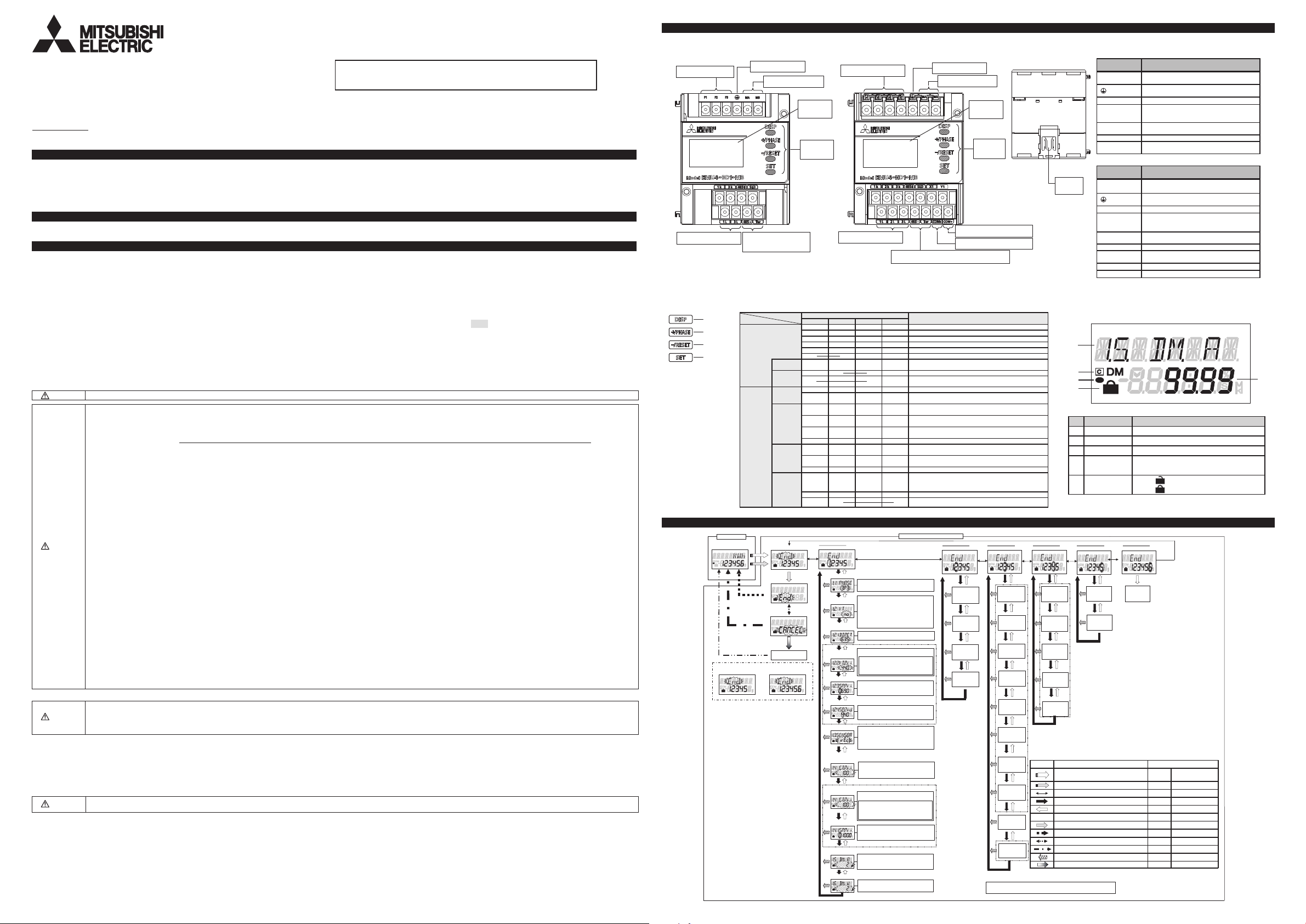
4. Name and function of each part
4.1 Name of each part
(1)
EMU4-BD1-MB
Voltage input terminals
Frame GND terminal
Power supply terminals
Current input terminals
Communication terminals
(
)
MODBUS RTU
4.2 Functions of operation buttons
Control buttons have many functions as below.
DISP button
+/PHASE button
-/RESET button
SET button
Me aning of sym bo l: ○ (P ress), □ (P ress m o re than 1 s ec), ◎ (P ress m o re th an 2 s ec) , ? ( Press b oth at the sam e tim e)
Mode
Op era ting
Set ting m od e
Conf irm ati on
Mo de
m ode
Operation
Co nta ct
dis pla y
Int
egr ate d
va lue
dis pla y
Men u
dis pla y
Set ting
m ode /
Set ting
dis pla y
/
Confi rm atio
n m od e /
Set ting
dis pla y
Confi rm atio
n d isp lay of
set ting
reflect ion
5. Procedures for setting
Operation mode
Measurement display
Cancel change
of setting value
Transition automatically
Example of display on
setting mode
*1: On confirmation mode, transition to operation mode.
*2: Transition only when selecting "SP" for "Primary current (VT)".
(For 3P4W, only special voltage is available when using VT.)
*3: Transition only when selecting "SP" for "Primary current (5A)".
for EMU4-HD1-MB only.
*4: Setting available
*5: Transition only when selecting "CO.P." for "Contact/pulse input on
or off".
*6: Transition only when selecting "PLS" for "Contact/pulse output on
or off".
*7: Transition only when selecting "on" for "Display CO2 or not".
*8: Transition only when connecting logging module.
*9: Not displayed on setting mode.
*10:<In case you choose “1P3” in (1) Phase wire system>
Youcan use direct measurement only.
Setting of primary voltage is skipped and setting is started from
"(7) Sensor type".
Rated voltage between 1- and
110V,and that between 1-and 3-phase is 220V
*11:Caution:
If there is no values above you want to set to, choose “SP” to
enable the special primary voltage and the special secondary
voltage.
In case you choose “3P4” (three-phase 4-wire system) in
(1) Phase wire system, the special voltage is only available
*12:Setting of special primary voltage
・ Press"
+/PHASE"
digit.
・ Press "SET" for the setting digit (flashing digit) to shift to lower.
・ Press "
DISP"
for the setting digit (flashing digit) to shift to upper.
・ You can set the upper three digit of the value to the range of
1V to 6600V.
Caution: In case you set the value except for between 1V and
6600V, indicate the error (E005).
When indicating the error, press"SET"to check the
setting values and set the new value again.
・ Press"SET"at the lowest digit to transition to
“(6) Special secondary voltage”.
The values set the upper fourth digit and lowers to are rounded
down.
After setting value flashes three times, transition to
Fix change of
setting value
"CANCEL" display
2-phase and 2- and 3-phase is
or "
+/PHASE"
End of setting menu
"End" display
"-" + "DISP"
Factroy default
Example of display on
confirmation mode
to choose the value at flashing
(2)
EMU4-HD1-MB
Voltage input terminals
LCD
display
Operation
button
Current input terminals
Name of Bu tton
SET -/R ES ET +/P HA SE DIS P
○
◎
◎
◎ ◎
◎
◎ ◎
◎ ◎
○
○ ○
(□ ) (□ )
○
○ ○
(□ ) (□ )
□
○
□
○
○ ○
◎ ◎
Setting menu 1
Basic setting
*1
.
system
(1) Phase wire
(2) Primary voltage
(Use or non-use of VT)
(3) Primary
voltage
(4) Primary voltage
(with VT)
(5) Special primary voltage
(6) Special secondary voltage
(7) Sensor type
(8) Primary current
(Direct sensor)
(
9) Primary current(5A sensor)
(10) Special primary current
(11) Current demand time
(12) Electric power demand time
Communication terminals (MODBUS RTU
Change me asu red ite ms
○
○
Set according to the phase wire system for the
measured circuit.
・If you measure directly (i.e. without VT):
→Choose “no” and press "SET"
to transition to "(3) Primary voltage (Direct)".
・If you measure with VT:
→Choose “yES” and press "SET"
to transition to "(4) Primary voltage (VT)".
(Supplement:“VT” means Voltage Transformer.)
<In case you choose “1P3” in (1) Phase wire system
Set the direct voltage according to voltage of the
Set the primary voltage of combined VT
Caution: *11
If you choose “SP”, transition to “(5) Special primary
voltage”.
If you choose the value except for “SP”, transition to
“(7) Sensor type”.
Set the special primary voltage of combined VT.
Setting range: 1V to 6600V
・Setting of special primary voltage *12
Set the special secondary voltage of combined VT.
Setting range: 1V to 220V
・Setting of special secondary voltage *13
・If you use direct sensor,
→choose “dirEct” and press"SET"
to transition to “(8) Primary current (Direct)”.
・If you use 5A sensor,
→choose “5A” and press"SET"
Set the primary current of combined CT (for direct
sensor).
After you choose the value, transition to
“(11) Current demand time”.
Set the primary current of combined CT (for 5A
sensor).
Supplement: *14
If you choose “SP”, transition to “(10) Special
primary current”
If you choose the value except for “SP”, transition
to
“(11) Current demand time”.
Set the special primary current of combined CT.
Setting range: 5A to 6000A (Default: 100.0A)
・Setting of special primary current *15
Set the current demand time.
On setting display, “s” means
means “minute”.
Set the electric power demand time.
On setting display, “s” means “second” and “M”
Change pha se
Change har mo nic ord er (a t ha rm oni c d isp lay)
Cle ar alar m (at ala rm keepi ng)
Tra nsi tion to co nfirm at ion mode
Tra nsi tion to setti ng m ode
Cle ar con tac t la tch
Tra nsi tion to pres et dis pla y
Tra nsi tion to res et d isp lay of all d ata
En ter sett ing m
Mo vin g up or down o f me nu num be r
(M ove at fast sp eed w hen press ing m ore than 1sec )
Change of s ettin g ite ms (fo rward )
Tra nsi tion to setti ng m enu num ber (a t fi nal se ttin g ite m)
Mo vin g up or down o f set ting valu e
(M ove at fast sp eed w hen press ing m ore than 1sec )
Change sett ing item s ( backwa rd)
○
Tra nsi tion to setti ng m enu num ber (a t b egin nin g s etting item )
Go ba ck to set ting m enu
Change sett ing item s ( for war d)
Tra nsi tion to setti
Change sett ing item s ( backwa rd)
○
Tra nsi tion to setti ng m enu num ber (a t b egin nin g s etting item )
Tra nsi tion to setti ng m enu
At "EN D" disp lay , m em ori ze c hange d s ettin g a nd tr ans itio n to
operati ng mo de
At "CA NC EL" displa y, annul ch anged set ting and tr ansitio n t o
operati ng mo de
Mo vin g up or down o f set ting valu e
Res et sett ing va lue s to fac tor y d efau lt ( onl y ef fect ive at
CA NCE L d isp lay )
Setting mode or confirmation mode
“second” and “M”
Frame GND terminal
Power supply terminals
Contact/ pulse output terminals
Contact/ pulse input terminals
Ev ent
enu
ng m enu num ber ( at f inal s etti ng it em)
Setting menu 2
Communication setting
MODBUS
address
MODBUS
baud rate
*2
MODBUS
parity
MODBUS
stop bit
*3
(3)
Back view
LCD
display
Operation
button
IEC rail
fixture
)
4.3 Functions of LCD
2
3
4
5
No. Indicator
1 Measured value Display measured value digitally.
2 Measured item Display measured item displayed on indicator No.1.
3 Communication Light when connecting communication unit.
4 Energy
5 Setting
Setting menu 3
nput/output
I
*5
of contact input
*6
Display CO2 or
*7
CO2 conversion
Display harmonic
Display harmonic
Display operating
Count method of
<Note>
For details of setting menu 1, 2, 3, 4, 5 and 6, refer to User's manual
Setting menu 4
Alarm setting
Contact/pulse
input
on or off
Reset method
Contact/pulse
output
on or off
Unit of pulse
output
not
setting
current or not
voltage or not
time or not
operating time
*4
*4
*4
Upper and lower
limit alarm
on or off
Upper and lower
limit alarm item
Upper and lower
limit alarm value
*13:Setting of special secondary voltage
Alarm delay time
*14:Supplement: If there is no values above you want to set to, choose “SP” to enable
*15:Setting of special primary current
Alarm reset
method
Symbol Behavior Operation of control button
Transition from operation mode to setting mode. "SET" + "-"
Transition from operation mode to confirmation mode. "SET" Press for 2 sec
Enter each setting display or transition to next item. "SET" Press once
No display Select setting value. "+" or "-" Press several times
Back to previous settting display. "DISP" Press once
Memorize changed setting and transition to operation mode.
Reset setting values to factory default. "SET" Press once
Names of signals of terminal block (EMU4-BD1-MB)
Terminal
symbol
P1、P2、P3
MA、MB
1k、1L、3k、3L
485+、485-
SLD Connect to ground (D type ground).
Ter Connect the “485- “terminal (the unit at end of
Names of signals of terminal block (EMU4-HD1-MB)
Terminal
symbol
P1/P1、P2/P0、
P3/P3、NC/P2
MA、MB
1k、1L、2k、2L、
3k、3L
485+、485-
SLD Connect to ground (D type ground).
Ter Connect the “485- “terminal (the unit at end of
X1、COM
Y1、COM
*1 It is being bonded to the conductive part of the product for safety reasons and being
connected to the terminal which is connected the outside protectioin grounding system.
Description
Connect t he voltage input wire for the
measurement circuit.
Connect to ground (D type ground).
(Protective earthing *1)
Connect the auxiliary power supply.
Connect the secondary output of the dedicated
current sensor connected to the measurement
circuit’s current wire.
Connect t he communic ation wire (MODBUS
RTU).
the link).
Connect the contact/ pulse input wire.
X
Connect the contact/ pulse output wire.
Y
SET
Description
Measurement
Setting menu 5
Logging setting
Logging module
ID setting
Clear logging
data
+/PHASE"
・ Press "
・ Press
"SET"
・ Press ”
DISP”
・ You can set the value to the range of 1V to 220V.
Caution: In case you set the value except for between 1V and 220V,
indicate the error (E005).
When indicating the error, press
the new value again.
"SET"
・ Press
primary current.
the special
+/PHASE"
・ Press "
・ Press
"SET"
DISP”
・ Press ”
・ You can set the value in the range from 5A to 6000A.
If the value is less than 10A, you can set upper two digits of it
If the value is 10A or more, you can set upper three digits of it.
Caution: In case you set the value except for the range from 5A and 6000A,
Select menu number or "End". "+" or "-" Press several times
Transition to "End" display. "SET" Press once
Select "CA
Cancel change of setting value. "SET" Press once
Skip other items during setting. "SET" Press for 1 sec
Light when measuring electric energy (consumption).
Indicator lights on setting mode.
SET
Indicator lights on confirmation mode.
SET
Setting menu 6
Test mode
Test mode
-/RESET"
or "
to choose the value at flashing digit.
"SET"
or "
-/RESET"
to choose the value at flashing digit.
*9
to check the setting values and set
Press both at the same
time for 2 sec
"SET" Press once
*8
for the setting digit (flashing digit) to shift to lower.
for the setting digit (flashing digit) to shift to upper.
at the lowest digit to transition to “(7) Sensor type”.
for the setting digit (flashing digit) to shift to lower.
for the setting digit (flashing digit) to shift to upper.
indicate the error (E005). When indicating the error, press
check the setting values and set the new value again.
NCEL". "+" or "-" Press once
"SET"
to
1
Page 2
6. Attaching and removing the unit
6.1 Mounting on IEC rail
8. Dimensions
●EMU4-BD1-MB ●EMU4-HD1-MB
CL
CL
Unit [mm]
*When showing the display part by cutting the panel face in mounting the IEC rail, cut the
panel at where it is more than 50mm away from the fulcrum of t he open / close of the door.
6.2 Mounting on the panel
・Dimensions of hole panel(77×45.5)
The panel hole dimensions are as shown below.
And it can be attached to a panel of thickness
1.6 – 4.5mm.
CL
(43.5)
44.527
67(Unit)
(75)
CL
76
Outline of the unit
2×
・Panel cut dimensions are made larger than the product
considering tolerance in panel cut. If you want to prevent dust
and other intrusion the gap of panel cut, cut the panel
according to the product to be mounted.
・Mounting
Attached to the panel with screws (2pcs).
Tightening torque : 0.63N・m
Mounting screws
4
φ
53.5 (Unit)
22.5
Recommended
screws
cross recessed head screw with captive washer
and flat washer
M3×10 2pcs
・Dimensions of hole panel(77×45.5)
The panel hole dimensions are as shown below.
And it can be attached to a panel of thickness
1.6 – 4.5mm.
MITSUBISHI
ELECTRIC
DISP
+/PHASE
Model
-/RESET
EMU4-HD1-MB
SET
CL
44.527
(43.5)
Panel
28 (75)
106(Attachment)
CL
67(Unit)
76
Outline of the unit
・Mounting
Mount the unit to mounting plate by m ounting screws (M3×10),
then mount the panel mounting attachment.
Tightening torque : 0.63N・m
4
φ
4×
53.5(Unit)
22 54.5(Attachment)
Mounting screws
Panel mounting
attachment
*Please screw up the panel mounting attachment where there are
high levels of vibration.
*The screws (mounting screws and screws for panel mounting
attachment) are supplied with panel mounting attachment.
Screws for panel
mounting
attachment
MITSUBISHI
ELECTRIC
DISP
+/PHASE
Model
-/RESET
EMU4-HD1-MB
SET
Panel
・Panel cut dimensions are made larger than the product
considering tolerance in panel cut. If you want to prevent dust
and other intrusion the gap of panel cut, cut the panel
according to the product to be mounted.
7. How to wire
7.1 Wiring
Follow the wiring diagram for external connections of this unit.
When using this unit, current sensor (EMU-CT50/CT100/CT250/CT400-A/600-A, EMU2-CT5 or EMU2-CT5-4W) is necessary.
1P2W (for low voltage circuit)
Power source side
1 2
P1 P2 P3
Split-type current sensor
EMU-CT***(50/100/250)
EMU-CT***-A(400/600)
K
l
1L
Load side
k
1K
Voltage transformer
L
3P4W (for high voltage circuit)
Power source side
2 3 0
1
Fuse :0.5A
MA MB
1k 3k
485+ SLD
Ter
3L1L
485-
RS485(MODBUS RTU)
P1/P1 P2/P0 P3/P3
1P3W/3P3W (for low voltage circuit)
Power source side
1 N
1 2
Split-type current sensor
EMU-CT***(50/100/250)
EMU-CT***-A(400/600)
K
L
Fuse: 0.5A
NC/P2
MA
MB
3
3
l
k
Load side
1L
1K
K
L
Caution
7.2 How to connect wires
・Use appropriate crimp-type terminal.
・Use electric wires as below, and tighten the terminal screws by the torque as below.
P1 P2 P3MAMB
1k
l
3L
3K
k
Fuse :0.5A
SLD
485+
Ter
485-
3L3k1L
RS485(MODBUS RTU)
・For protection against noise, transmission lines and input/output lines shall not be placed close
to or bound together with the power lines and high-voltage lines. Keep distance as below
between them. (except for the terminal block)
Condition distance
High-voltage line 600V or less 300mm or longer
Other high-voltage line 600mm or longer
・For the actual usage, connect the FG terminal to ground. (D-type ground: Type 3) Connect it
directly to the ground terminal.
This is being bonded to the conductive part of the product for safety reasons and being
connected to the terminal which is connected the outside protection grounding system.
・Do not connect to FG terminal during the insulation resistance test and pressure test.
【EMU4-BD1-MB】
Current
transformer ***/ 5A
485+ SLD
1k 2k 3k
Split-type current sensor
EMU-CT-A
K
K
L
K
L
K
L
Load side
* Fuse:P405H (by Daito Communication Apparatus Co., Ltd) equivalent.
* For a low voltage circuit, grounding of the secondary sides of VT (or CT) is not necessary.
・Make sure that before connecting the cable, the orientat ion of the current sensor is correct for attachment . K to L is the correct direction. K: power source side, L: load side
・EMU-CT50, EMU-CT100, EMU-CT250, EMU-CT400-A,EMU-CT600-A are extendable up to 50m.
・EMU2-CT5, EMU2-CT5-4W are extendable up to 11 m, using together with a extension cable. T
CW-5S(L) side.
・EMU-CT50/100/250/400-A/600-A is used only for low voltage ci rcuit. (Maximum voltage: 460V) It cannot be used for a high voltage ci rcuit. EMU2-CT5 and EMU2-CT5-4W should be used with the secondary side (5A) of transformer transfixed.
If they are used for the circuit directly, they should be used under 200V. (Maximum voltage: 260V)
voltage of the circuit connected to this unit directly is 260V f or EMU4-BD1-MB, or 277 / 480V for EMU4-HD1-MB. For the circuit over this voltage, use the transformer. Using the transformer, primary voltage is configurable up to
・Maximum
6600V. secondary voltage is fixed to 110V. (special Primary voltage of VT can be set up to 6600V in any, and special secondary voltage of VT can be set up to220V in any.)
・When screwing the terminals at both ends of the terminal block, be caref ul not to touch the projecti
・For MODBUS RTU communication wiring, recommended to have the extra length wires about 200mm (When extended to B / NET transmission from MODBUS RTU communication, use of MODBUS RTU communication wiring is possi ble).
・Do not ground the secondary side of the current sensor.
l
1L
L
K
L
K
L
1K
k
l
2L
2K
k
l
3L
3K
k
485-
Ter
1L 2L 3L
RS485(MODBUS RTU)
X1 Y1
COMx
COM
Y
Contact/
pulse output
Contact/
Pulse input
Power supply terminals,
voltage input terminals
Current input terminals,
input/ output terminals
【EMU4-HD1-MB】
Power supply terminals,
voltage input terminals
Current input terminals,
input/ output terminals
o extend the wire further, use the current transformer CW-5S(L) for split-type instrument in combination, extending the secondary wiring on
on of the terminal block cover.
3P3W (for high voltage circuit)
Power source side
2
1
K
L
Load side
Applicable wire Tightening
AWG24 - 16 (0.2~1.25mm2)
(single wire / stranded wire)
AWG22 - 16 (0.3~1.25mm2)
(single wire / stranded wire)
Applicable wire Tightening
AWG26 - 14 (0.12~0.2mm2)
(single wire / stranded wire)
AWG22 - 16 (0.3~1.25mm2)
(single wire / stranded wire)
3
Current
transformer ***/ 5A
Split-type current sensor
EMU-CT-A
K
L
K
K
L
L
Voltage transformer
l
k
l
k
P1/P1 P2/P0 P3/P3
NC/P2
485+
1k 2k 3k
485-
1L 2L 3L
RS485(MODBUS RTU)
torque
0.8 N・m
0.5 - 0.6N・m
torque
0.8 - 1.0 N・m
0.5 - 0.6N・m
Fuse: 0.5A
MA
SLD
Ter
X1 Y1
MB
COMx
COM
Y
Contact/
pulse output
Contact/
Pulse input
Recommended
crimp-type terminal
For M3 screw of
external diameter
below 5.6mm
For M3 screw of
external diameter
below 5.6mm
Recommended
crimp-type terminal
For M3.5 screw of
external diameter
below 5.6mm
For M3 screw of
external diameter
below 5.6mm
90
53.5
90
53.5
22.5
27.5 43.5
67
754
6015
27 35.4
22.5
4 75
27.5 43.5
67
15 60
9. Specifications
Item Specifications
Model EMU4-BD1-MB EMU4-HD1-MB
Phase-wire system
Measurement item
Voltage
circuit
(*1)
single-phase 2-wire,
three-phase 3-wire
single-phase 3-wire
single-phase 2-wire / single-phase 3-wire /
three-phase 3-wire
Electric energy (consumption, regeneration), Current,
Current demand, Voltage, Electric power, Electric power
demand, Reactive power, Power factor, Frequency,
Reactive energy, Operating time
110V, 220V AC 110V, 220V, 440V AC
AC110V (b/w 1- and 2-side, 2- and 3-side),
AC220V(b/w 1- and 3-side)
single-phase 2-wire / single-phase 3-wire /
three-phase 3-wire / three-phase 4-wire
Electric energy (consumption, regeneration), Current, Current
demand, Voltage, Electric power, Electric power demand, Reactive
power, Apparent power, Power factor, Frequency, Harmonic current,
Harmonic voltage, Reactive energy,
count value, Operating time, Equivalent CO
Periodic electric energy, Pulse
2
AC110V (b/w 1- and 2-side, 2- and 3-side),
AC220V(b/w 1- and 3-side)
three-phase 4-wire Non-compliant Min: AC63.5V/110V, Max: AC277V/480V
Rating
Current circuit
50A, 100A, 250A, 400A, 600A AC
(The dedicated split type current sensor is used. Each value refers to the current at the primary side of the current sensor)
5A AC
(The dedicated split type current sensor is used. 5A current sensor is used together with the current transformer (CT), and the
primary-side current is configurable up to 6000A.)
Secondary-side current is up to 66.66m A AC.
Frequency 50Hz-60Hz
Auxiliary power supply rating 100-240VAC (+10%,-15%), 50Hz-60Hz, Transient overvoltage 4,000V
Consumption VA(*2) 10VA ( AC110V:9VA,AC220V:10VA)
Transient overvoltage
Measuring circuit: CAT Ⅲ, Auxiliary power supply: CAT Ⅲ.
Measurable circuit count 1 circuit
External input
External output
Input signal type
Rated input
voltage/current
Output signal type
Rated open/close
voltage/current
None
None
No voltage a-contact 1 input
5V DC 7mA
No voltage a-contact 1 output
35V DC 75mA or 24V AC 75mA (Power factor = 1)
Operating temperature -5 - +55℃ (Under the conditions indicated in section 3.1)
Operating humidity 30 - 85%RH (No condensation)
Storage temperature -10 - +60℃
Operating altitude 2000m or below
Standard(*3)
Possible combination current sensor for
UL
EMC: EN61326-1: 2013 UL: UL61010-1
LVD: EN-61010-1: 2010
EMU-CT50/100/250,EMU2-CT5,EMU-CT400-A/600-A EMU-CT50/100/250,EMU2-CT5,EMU-CT400-A/600-A
Possible combination optional unit for UL EMU4-LM, EMU4-CM-C *4
*1:The transformer of star-delta connection and delta-star connection can’t measure connectly because of the phase shifting.
*2: The maximum value of consumption VA is described.
*3:When combine it with a B/NET Communication Unit(Model:EMU4-CM-B), it becomes out of a conformity standard.
*4: EMU4-LM enables to memorize the data of various quantities related to electricity for a certain period. EMU4-CM-C is communicationunit for CC-Link
.
10. Optional devices connectable to this unit
Optional devices connectable to this unit are as follows.
Device Model Connection terminal
Optional Unit B/NET Communication Unit for Energy Measuring Unit EMU4-CM-B The connecter on the left side of the unit
CC-Link Communication Unit for Energy Measuring Unit EMU4-CM-C The connecter on the left side of the unit
CC-Link IE Field Network Basic Communication Unit for Energy Measuring Unit EMU4-CM-CIFB The connecter on the left side of the unit
Logging Unit for Energy Measuring Unit EMU4-LM The connecter on the left side of the unit
For the details of each device and the way to connect, refer to the manual of the device.
11. Warranty
・The warranty is effective until the earlier of 1 year after the date of your purchase or 18 months after manufacturing. Repair shall be charged for the case failures occur due
to your intent or fault even during the warranty period.
・If the equipment is used in a manner not specified by the manufacturer, the protection provided by the equipment may be impaired
・Our company shall not be liable to compensate for any loss arising from events not attributable to our company, opportunity loss and lost earning of the cus
tomer due to failure
of the product, and loss, secondary loss, accident compensation, damage to other products besides our products and other operations caused by a special reason regardless
of our company’s predictability.
Caution
If an abnormal sound, bad-smelling sm oke, fever break out from this unit, switch it off promptly and don’t use it
12. Customer Service
HEAD OFFICE: TOKYO BUILDING, 2-7-3, MARUNOUCHI, CHIYODA-KU, TO KYO 100-8310, Japan
Please refer to “catalog” or “User’s manual (Details)” for more details.
27 35.4
 Loading...