

Page 1
i-MiEV - ENGLISH - OHAE12E1
OWNER’ S MANUAL
i -M i EV
Page 2

Table of contents
Overview
General information
Charging 1
Locking and unlocking 2
Seat and seat belts 3
Instruments and controls 4
Starting and driving 5
For pleasant driving 6
For emergencies 7
Vehicle care and Maintenance 8
Specifications 9
Page 3
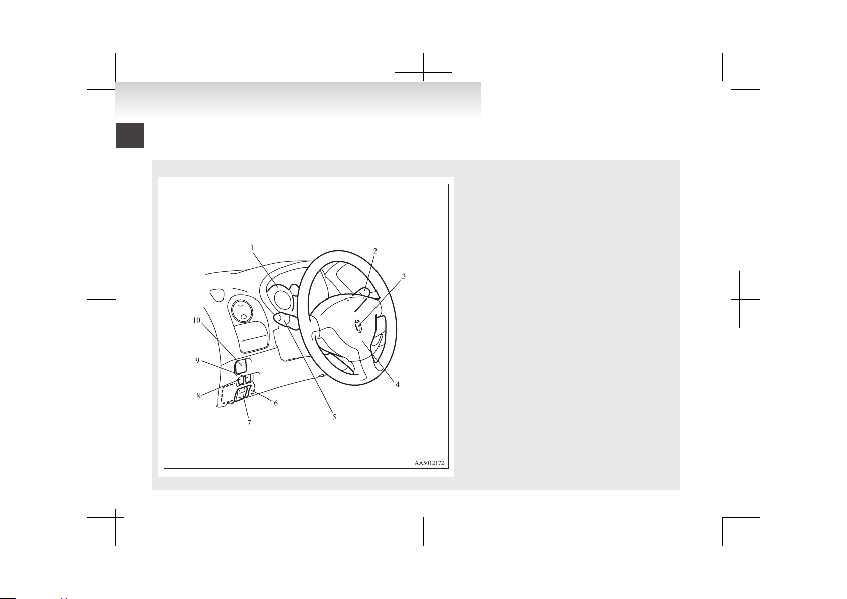
Instruments and Controls (Driver’s area)
E00100105789
LHD
1. Instruments p. 4-02
2. Windscreen wiper and washer switch p. 4-16
Rear window wiper and washer switch p. 4-17
3. Electric motor switch p. 5-07
4. Supplemental restraint system - airbag (for driver's seat) p. 3-20
Horn switch p. 4-19
5. Combination headlamps and dipper switch p. 4-11
Turn-signal lever p. 4-14
Front fog lamp switch* p. 4-15
Rear fog lamp switch p. 4-15
6. Fuses p. 8-20
7. Regular charging opener p. 1-05
8. Headlamp levelling switch p. 4-13
9. Active Stability Control (ASC) OFF switch p. 5-17
10. Electric remote-controlled outside rear-view mirrors
switch p. 5-05
Overview
Page 4
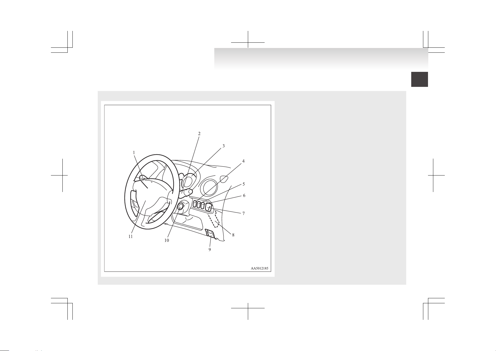
RHD
1. Combination headlamps and dipper switch p. 4-11
Turn-signal lever p. 4-14
Front fog lamp switch* p. 4-15
Rear fog lamp switch p. 4-15
2. Windscreen wiper and washer switch p. 4-16
Rear window wiper and washer switch p. 4-17
3. Instruments p. 4-02
4. Headlamp levelling switch p. 4-13
5. Active Stability Control (ASC) OFF switch p. 5-17
6. Rear window demister switch p. 4-18
7. Electric remote-controlled outside rear-view mirrors
switch p. 5-05
8. Fuses p. 8-20
9. Regular charging opener p. 1-05
10. Electric motor switch p. 5-07
11. Supplemental restraint system - airbag (for driver's seat) p. 3-20
Horn switch p. 4-19
Overview
Page 5
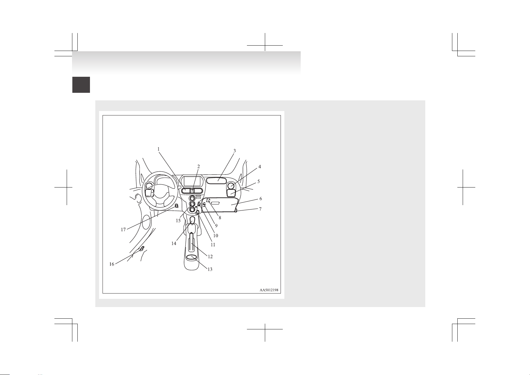
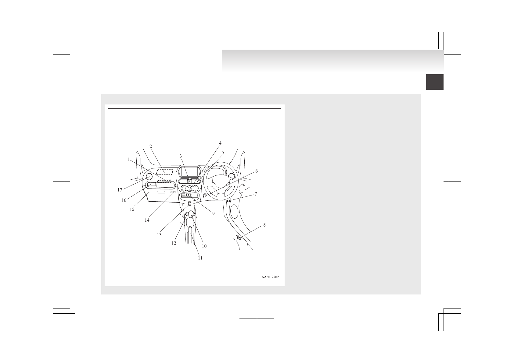
Instruments and Controls (Instrument panel)
E00100105792
LHD
1. Centre ventilators p. 6-02
2. Hazard warning flasher switch p. 4-15
3. Supplemental restraint system - airbag (for front passenger) p. 3-20
4. Side ventilators p. 6-02
5. Cup holder p. 6-15
6. Glove box p. 6-14
7. Bonnet release lever p. 8-07
8. Front passenger’s airbag ON-OFF switch p. 3-23
9. Card holder p. 6-14
10. Rear window demister switch p. 4-18
11. Accessory socket p. 6-11
12. Parking brake lever p. 5-03
13. Cup holder p. 6-15
14. Selector lever p. 5-09
15. Air conditioning p. 6-03
16. Quick charging lid opener p. 1-08
17. Heated seat switch* p. 3-04
Overview
Page 6
RHD
1. Secret box p. 6-14
2. Supplemental restraint system - airbag (for front passenger) p. 3-20
3. Hazard warning flasher switch p. 4-15
4. Air conditioning p. 6-03
5. Centre ventilators p. 6-02
6. Heated seat switch* p. 3-04
7. Bonnet release lever p. 8-07
8. Quick charging lid opener p. 1-08
9. Front passenger’s airbag ON-OFF switch p. 3-23
10. Selector lever p. 5-09
11. Parking brake lever p. 5-03
12. Cup holder p. 6-15
13. Accessory socket p. 6-11
14. Card holder p. 6-14
15. Glove box p. 6-14
16. Cup holder p. 6-15
17. Side ventilators p. 6-02
Overview
Page 7
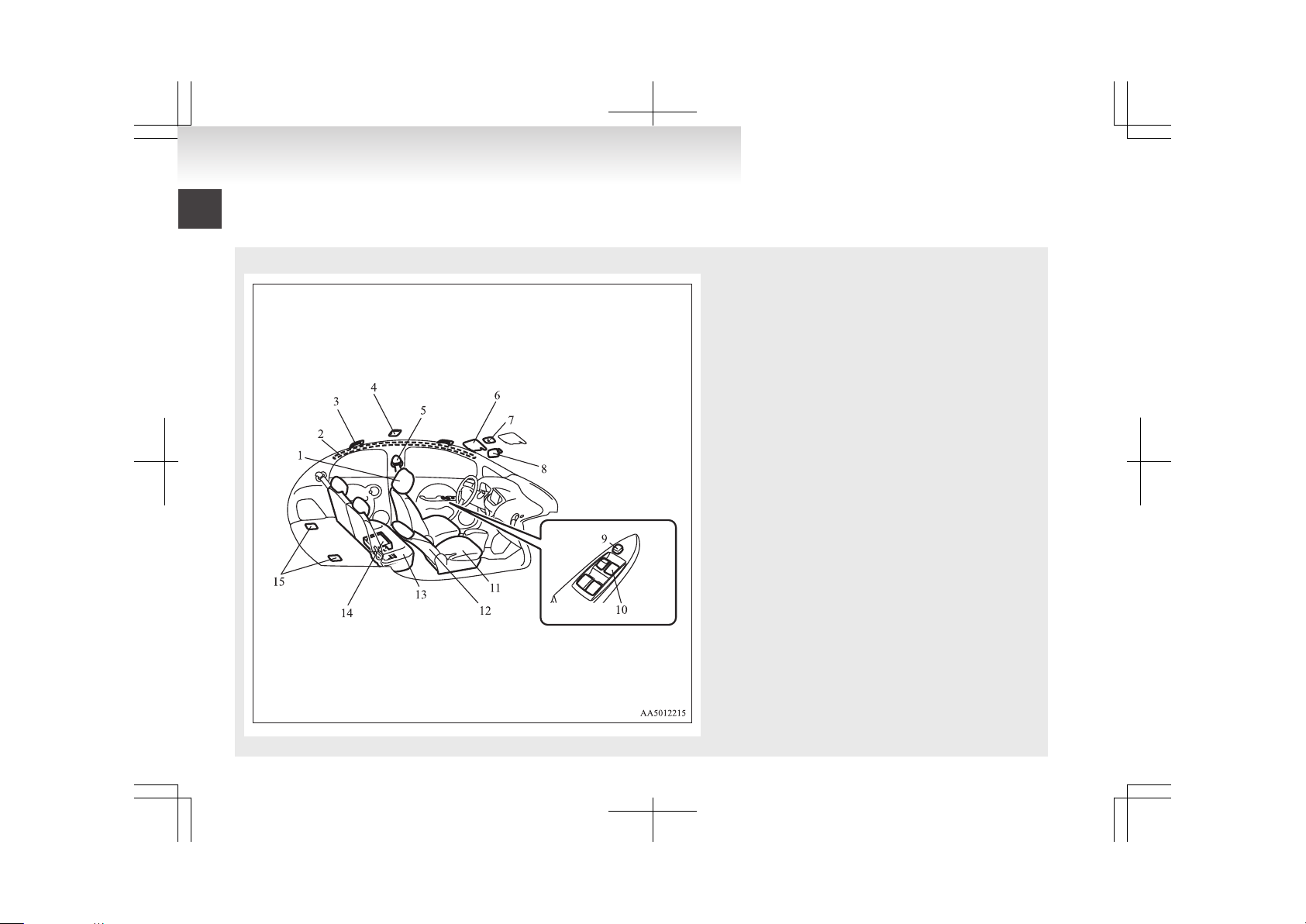
Interior
E00100204233
LHD
1. Head restraints p. 3-07
2. Supplemental restraint system - curtain airbag p. 3-27
3. Assist grip p. 6-16
4. Room lamp (rear) p. 6-13, 8-24
5. Seat belts p. 3-08
6. Sun visor p. 6-10
Vanity mirror p. 6-10
Card holder p. 6-11
7. Map & room lamps (front) p. 6-12, 8-24
8. Inside rear-view mirror p. 5-05
9. Electric window lock switch p. 2-10
10. Electric window control switch p. 2-09
11. Front seat p. 3-03
12. Supplemental restraint system - side airbag (for front
seats) p. 3-27
13. Rear seat p. 3-05
14. Tyre repair kit p. 7-04
15. Tether anchorages for child restraint system p. 3-18
Overview
Page 8
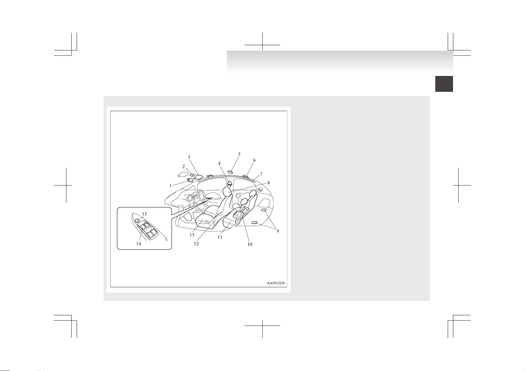
RHD
1. Inside rear-view mirror p. 5-05
2. Map & room lamps (front) p. 6-12, 8-24
3. Sun visor p. 6-10
Vanity mirror p. 6-10
Card holder p. 6-11
4. Seat belts p. 3-08
5. Room lamp (rear) p. 6-13, 8-24
6. Assist grip p. 6-16
7. Supplemental restraint system - curtain airbag p. 3-27
8. Head restraints p. 3-07
9. Tether anchorages for child restraint system p. 3-18
10. Tyre repair kit p. 7-04
11. Rear seat p. 3-05
12. Supplemental restraint system - side airbag (for front
seats) p. 3-27
13. Front seat p. 3-03
14. Electric window control switch p. 2-09
15. Electric window lock switch p. 2-10
Overview
Page 9
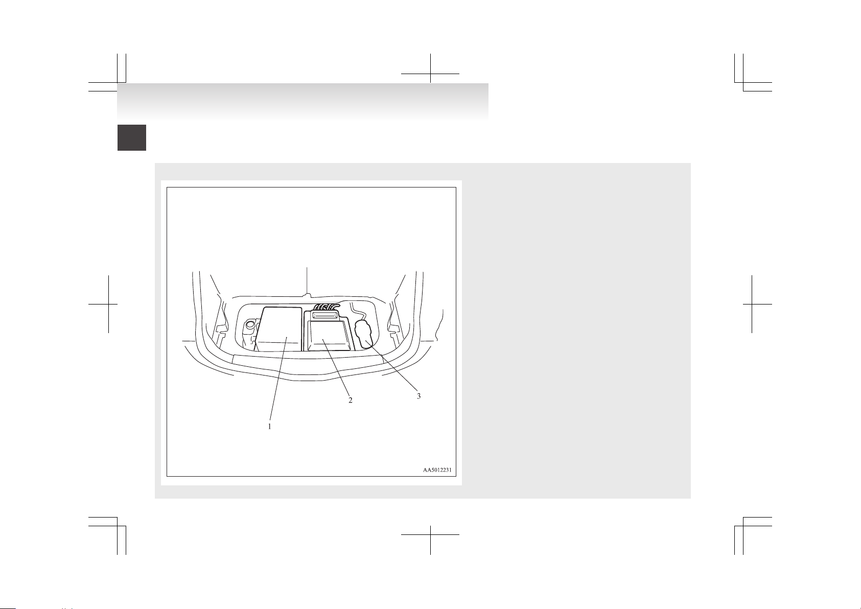
Electric motor unit room
E00100800013
1. On board charger/DC-DC converter p. 8-06
2. Inverter p. 8-06
3. Brake electric vacuum pump
Overview
Page 10
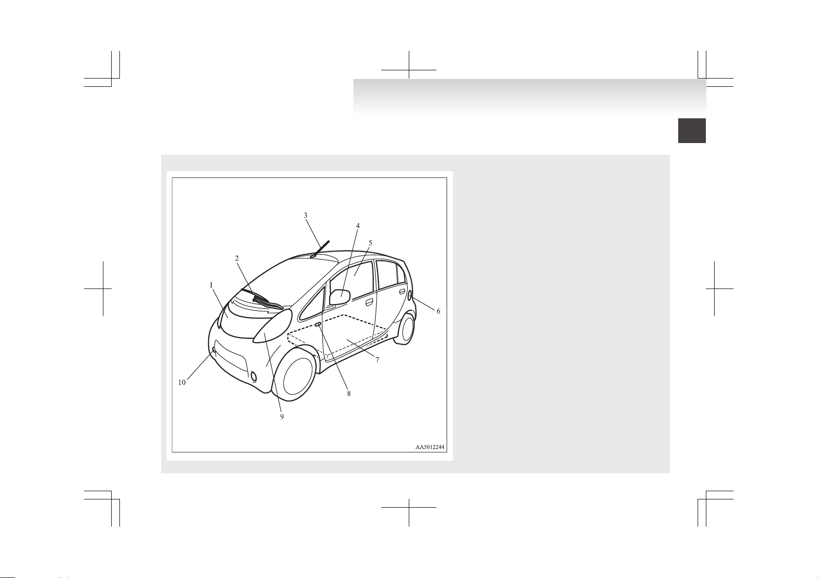
Outside (Front)
E00100504887
1. Bonnet p. 8-07
2. Windscreen wipers p. 4-16
3. Antenna p. 6-10
4. Outside rear-view mirror p. 5-05
5. Electric window control p. 2-09
6. Quick charging lid p. 1-08
7. Traction battery p. 8-06
8. Side turn-signal lamps/Hazard warning lamps p. 4-09, 8-24, 8-30
9. Headlamps p. 4-11, 8-24, 8-24, 8-30
Position lamps p. 4-11, 8-24, 8-24, 8-30
Front turn-signal lamps/Hazard warning lamps p. 4-09, 8-24, 8-24,
8-30
10. Front fog lamps* p. 4-15, 8-24, 8-31
Daytime running lamps* p. 4-13, 8-24, 8-31
Overview
Page 11
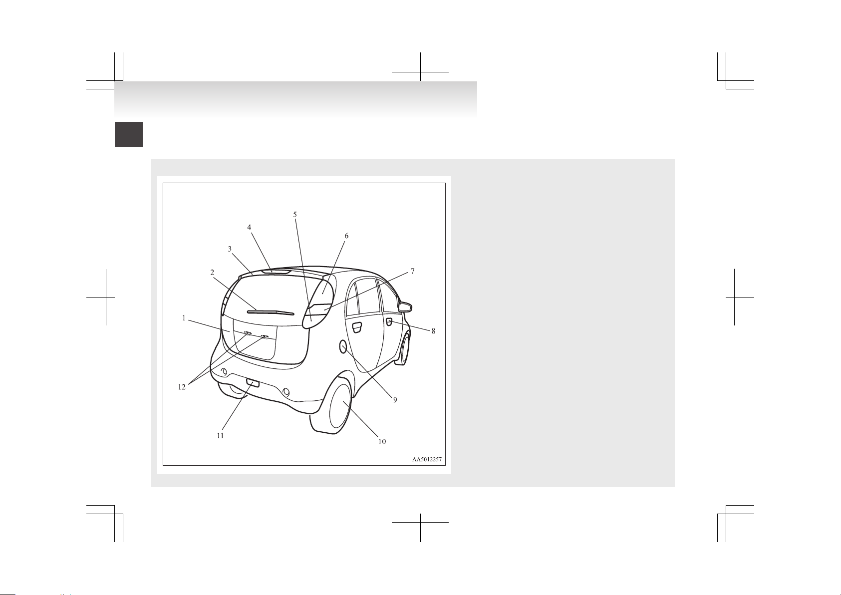
Outside (Rear)
E00100504702
1. Tailgate p. 2-08
2. Rear window wiper p. 4-17
3. Rear spoiler
4. High-mounted stop lamp p. 8-24, 8-34
5. Reversing lamps p. 8-24, 8-33
6. Stop lamps/Tail lamps p. 4-14, 8-24, 8-33
7. Turn-signal lamps/Hazard warning lamps p. 4-14, 4-15, 8-24, 8-33
8. Keyless entry system p. 2-03
Locking and unlocking the doors p. 2-05
9. Regular charging lid p. 1-05
10. Tyre inflation pressures p. 8-15
Tyre rotation p. 8-16
Tyre chains p. 8-17
Size of tyres and wheels p. 9-05
11. Rear fog lamp p. 4-15, 8-24, 8-32
12. Licence plate lamps p. 4-11, 8-24, 8-34
Overview
Page 12
Familiarizing yourself with i-MiEV................................................02
Installation of accessories................................................................03
Modification/alterations to the electrical systems............................04
Genuine parts...................................................................................04
Disposal information for used batteries...........................................04
Cautions and actions to deal with intense heat................................05
Cautions and actions to deal with intense cold................................06
General information
Page 13

Familiarizing yourself with
i-MiEV
E00202600016
This section describes features that the i-MiEV has
as an electric vehicle and gives precautions that
you should observe. It is important. Please read it
carefully.
Main features
E00202700017
l
Energy required for driving is only electricity and fuel supply is not required.
l
The traction battery and electric motor unit
are mounted outside the passenger compartment. In this way, passenger space is obtained for riding of four adults.
l
With the high performance motor, noise and
vibration during driving are greatly limited
and powerful acceleration can also be obtained.
l
With regenerative braking, the traction battery is automatically charged when the accelerator is released.
l
The vehicle can be charged from general power outlets (rated AC 220-240 V).
l
Charge with the quick charger for i-MiEV is
also available.
l
The creeping behaviour occurs in i-MiEV
like a vehicle with automatic transmission.
Regenerative braking
It is equivalent to engine braking of an engine vehicle. If you step off the accelerator pedal during driving, motion energy is converted into electric energy
using the motor as a power generator.
In this conversion, braking force is generated and
converted electric energy is charged in the traction
battery.
Regenerative braking is stronger in the order of the
selector lever position of “C” (COMFORT), “D”
(DRIVE), “B” (BRAKE).
Put the selector lever to the “B” (BRAKE) or “C”
(COMFORT) position according to the driving condition.
“B”: Strong regenerative braking (For downhill)
“C”: Weak regenerative braking (For long cruising)
Traction battery
E00202800018
l
It is the battery to operate the motor (electric
motor unit) and the air conditioning.
In addition to the traction battery, i-MiEV
has the auxiliary battery to operate lamps, wipers, etc.
l
Compact, light-weight lithium ion battery
with high energy density is used for the traction battery.
l
The lithium ion battery has the following characteristics. Please read this carefully and
treat the battery paying attention to the following:
Characteristics
l
It is not necessary to consume the battery completely before charging.
l
The capacity is gradually degraded depending on time used and operating conditions.
l
The performance may be changed due to the
outside temperature. At low temperature, in
particular, the cruising range is short and the
charging time is long, compared to operation
at normal temperature.
l
If you store your vehicle at an extremely
high or low temperature, the battery capacity
may be lowered.
l
The battery is gradually discharged without
use and the battery charge is lowered.
Precautions for operation
l
Do not store your vehicle with the energy level gauge showing 0 bars.
Doing so could damage the traction battery.
The battery may have to be replaced depending on the low capacity.
l
If you do not use your vehicle for a long
time, please charge the traction battery to the
full every 3 months so that the energy level
gauge may not be 0 bars.
l
MITSUBISHI MOTORS collects traction batteries. If you scrap your vehicle, please consult a MITSUBISHI MOTORS Authorized
Service Point.
NOTE
l
The progress of the battery capacity loss depends on the vehicle usage and the environment.
We recommend to do regular charging from
2 bars or less to charge completely at least
once in 3 months.
The procedure lets the battery remaining indicator adjusted automatically.
Cruising range
E00202900019
l
Even if the charge level is the same, the cruising range may vary depending on the driving
conditions. Since driving at high speed or
climbing on a hill requires higher consumption of the traction battery than usual, the
cruising range is shortened.
l
Since the air conditioning (cooling or heating) consumes power of the traction battery,
its operation results in a shorter cruising
range. Maintain an appropriate temperature.
General information
02
Page 14

l
Put the selector lever to the “B” (BRAKE) or
“C” (COMFORT) position according to the
road condition. To charge the traction battery
with appropriate use of regenerative braking
can increase the cruising range.
Installation of accessories
E00200301003
We recommend you to consult a MITSUBISHI
MOTORS Authorized Service Point.
l
The installation of accessories, optional
parts, etc., should only be carried out within
the limits prescribed by law in your country,
and in accordance with the guidelines and
warnings contained within the documents accompanying this vehicle.
l
Installing electric components incorrectly
could lead to a fire. See the “Modification/alterations to the electrical systems” section
within this owner’s manual.
l
Using a cellular phone or radio set inside the
vehicle without an external antenna may
cause electrical system interference, which
could lead to unsafe vehicle operation.
l
Tyres and wheels which do not meet specifications must not be used.
Refer to the “Specifications” section for information regarding wheel and tyre sizes.
Important points!
Due to large number of accessory and replacement
parts of different manufactures available in the market, it is not possible, not only for MITSUBISHI
MOTORS, but also for a MITSUBISHI MOTORS
Authorized Service Point, to check whether the attachment or installation of such parts affects the
overall safety of your MITSUBISHI-vehicle.
Even when such parts are officially authorized, for
example by a “general operators permit” (an appraisal for the part) or through the execution of the
part in an officially approved manner of construction, or when a single operation permit following
the attachment or installation of such parts, it cannot be deduced from that alone, that the driving safety of your vehicle has not been affected.
Consider also that there basically exists no liability
on the part of the appraiser or the official. Maximum safety can only be ensured with parts recommended, sold and fitted or installed by a
MITSUBISHI MOTORS authorized Service Point
(MITSUBISHI MOTORS genuine replacement
parts and MITSUBISHI MOTORS accessories).
The same also pertains to modifications of
MITSUBISHI vehicles with respect to the production specifications. For safety reasons, do not attempt any modifications other than those that follow the recommendations of a MITSUBISHI
MOTORS authorized Service Point.
General information
03
Page 15
Modification/alterations to the
electrical systems
E00200400414
MITSUBISHI MOTORS CORPORATION has always manufactured safe, high quality vehicles. In
order to maintain this safety and quality, it is important that any accessory that is to be fitted, or any
modifications carried out which involve the electrical systems, should be carried out in accordance
with MITSUBISHI guidelines.
CAUTION
l
If the wires interfere with the vehicle
body or improper installation methods
are used (protective fuses not included,
etc.), electronic devices may be adversely
affected, resulting in a fire or other accident.
Genuine parts
E00200500499
MITSUBISHI MOTORS has gone to great lengths
to bring you a superbly crafted automobile offering
the highest quality and dependability.
Use MITSUBISHI MOTORS Genuine Parts, designed and manufactured to maintain your
MITSUBISHI MOTORS automobile at top performance. MITSUBISHI MOTORS Genuine Parts
are identified by this mark and are available at all
MITSUBISHI MOTORS Authorized Service
Points.
Disposal information for used
batteries
E00201300045
Your vehicle contains batteries
and/or accumulators.
Do not mix with general household waste.
For proper treatment, recovery
and recycling of used batteries,
please take them to applicable collection points, in accordance
with your national legislation
and the Directives 2006/66/EC.
MITSUBISHI MOTORS collects traction batteries. If you
scrap your vehicle, please consult a MITSUBISHI MOTORS
Authorized Service Point.
By disposing of these batteries
correctly, you will help to save
valuable resources and prevent
any potential negative effects on
human health and the environment which could otherwise
arise from inappropriate waste
handling.
General information
04
Page 16
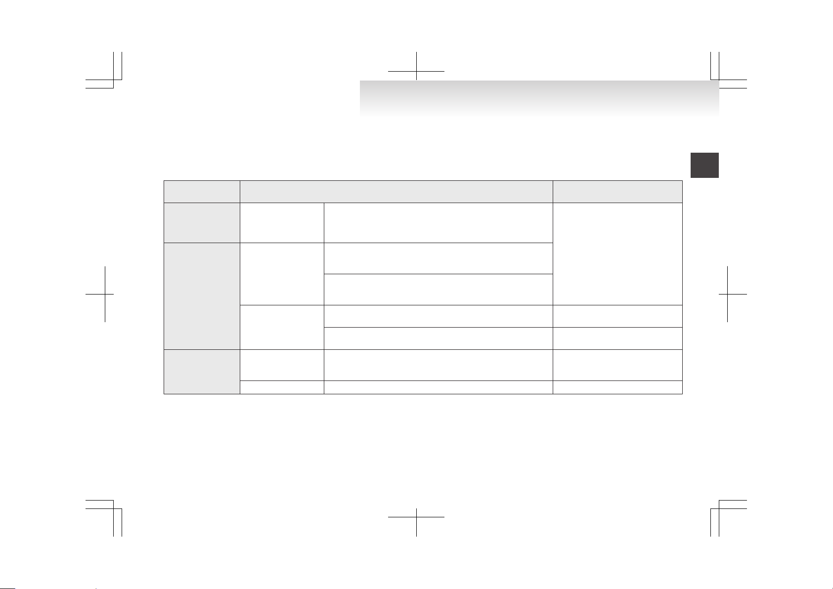
Cautions and actions to deal with intense heat
E00203000017
l
When the vehicle is driven in a high ambient temperature, its air-conditioner performance can be insufficient. Also, using the air conditioner can reduce the
vehicle’s cruising range.
l
When the ambient temperature is approximately 40 °C or higher, the phenomena described below may occur. Please take the described corrective action.
Approx. ambient tem-
perature
Phenomena
Corrective action
Approx. 40 °C to
45 °C
Startup and driving
During quick charging, repeated high-speed driving, or repeated uphill
driving, the power down warning lamp* comes on and the motor output is restricted to protect the traction battery or motor (electric motor
unit).
Stop the vehicle for a while, avoid
quick charging, and wait for the power
down warning lamp* to go off.
Approx. 45 °C to
60 °C
Startup and driving
During continued high-speed driving or continued uphill driving, the
power down warning lamp* comes on and the motor output is restricted to protect the traction battery or motor (electric motor unit).
If you continue driving after the power down warning lamp* has come
on, the vehicle may stop when you have driven a few kilometres. (The
vehicle stops when the traction battery temperature reaches 60 °C.)
Charging and battery
Charging may become impossible. (When the traction battery temperature is 60 °C or higher, charging is limited to protect the traction battery.
Park in a well-ventilated, shady place.
The traction battery capacity decreases more quickly, and the cruising
range decreases more quickly.
When you park, do so in a well-ventilated, shady place.
Approx. 60 °C or high-
er
Startup and driving
The power down warning lamp* comes on, and the vehicle may stop.
(The vehicle stops when the traction battery temperature reaches
60 °C.)
Park in a well-ventilated, shady place,
avoid quick charging, and wait for the
power down warning lamp* to go off.
Charging and battery Deterioration of the traction battery becomes extremely fast. Park in a well-ventilated, shady place.
NOTE
l
*: Refer to “Power down warning lamp” on page 4-11. Illumination of the power down warning lamp does not indicate a malfunction.
General information
05
Page 17
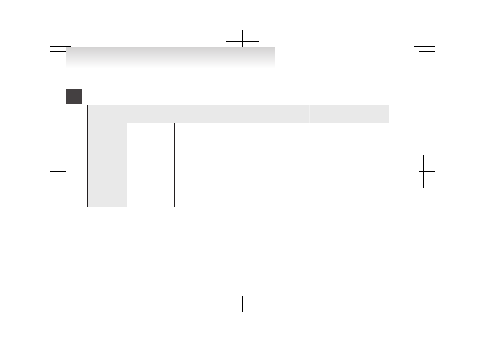
Cautions and actions to deal with intense cold
E00203100021
l
When the vehicle is driven in a low ambient temperature, its heater performance can be insufficient. Also, using the heater can reduce the vehicle’s cruising
range.
l
When the ambient temperature is approximately -15 °C or lower, the phenomena described below may occur. Please take the described corrective action.
Approx.
ambient tempera-
ture
Phenomena Corrective action
Approx. -15 °C or
lower
Startup and driving
l
Motor output is restricted, and the power down warning lamp*
1
may come on.
l
If the traction battery’s remaining power is low (approximately
30%), driving performance decreases by approximately 20%.
Continue driving. (As the traction battery
temperature rises, the output restriction
will gradually be removed.)
Charging and battery
l
Charging times get longer.
• Regular charge: Becomes approximately 2-3 hours longer at
-15 °C.
• Quick charge: Becomes approximately 2 hours longer
at - 15 °C.
• Charging times get longer with further reductions in temperature.
l
Charging may complete with 16 bars of energy level gauge*
2
does not go on. Even if charging is completed with 16 bars of energy level gauge come on, the 16th bar may go off early. The lighting bars may decrease with further reductions in temperature.
When you have finished driving, charge
the traction battery before its temperature
falls.
General information
06
Page 18
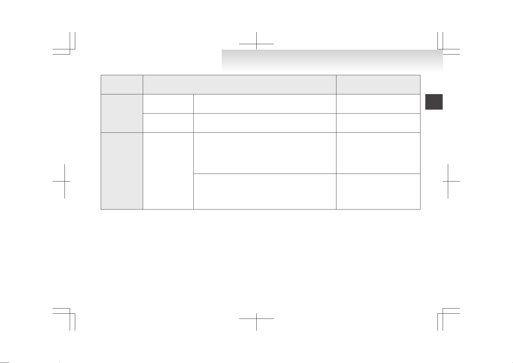
Approx.
ambient tempera-
ture
Phenomena Corrective action
Approx. -25 °C or
lower (including
the phenomena of
approx. -15 °C or
lower)
Startup and driving
l
Driving performance decreases by approximately 50%. Continue driving. (As the traction battery
temperature rises, the output restriction
will gradually be removed.)
Charging and battery
l
Charging may become impossible. (When the traction battery temperature is -25 °C or lower, charging is limited to protect the traction battery.)
When you have finished driving, charge
the traction battery before its temperature
falls.
Approx. -30 °C or
lower (including
the phenomena of
approx. -15 °C or
lower and -25 °C or
lower)
Startup and driving
l
The ready indicator*3 does not come on, and startup may not be
possible.
l
In the worst-case scenario, the vehicle may become undrivable
(with the energy level gauge and cruising range indications still
shown).
In the daytime, wait for the temperature
to rise. When the temperature in the vicinity of the traction battery has risen, start
up. (Once you start driving, the traction
battery temperature will rise. Provided
the traction battery has some power, the
vehicle will not stop.)
l
Regenerative braking performance may decrease. To decelerate, press the brake pedal.
(The deterioration in regenerative braking performance is like a deterioration in
engine braking in a petrol- or diesel-engine version. If you press the brake pedal, the brakes will work.)
NOTE
l
*1: Refer to “Power down warning lamp” on page 4-11. Illumination of the power down warning lamp does not indicate a malfunction.
l
*2: Refer to “Energy level gauge” on page 4-06.
l
*3: Refer to “Ready indicator” on page 4-09.
General information
07
Page 19

Page 20
Battery..........................................................................................1-02
Basic knowledge for charging......................................................1-02
EV charging cable........................................................................1-03
Regular charging (charging method with rated AC
220-240 V outlet).....................................................................1-04
Quick charging (charging method with quick charger)................1-08
Charging
1
Page 21

Battery
E08300100014
There are two types of batteries installed in your vehicle: a traction battery for operating the motor (electric motor unit) and air conditioning as well as an
auxiliary battery for starting the electric motor unit
and operating the lamps, wipers, etc. This chapter
explains charging of the traction battery.
NOTE
l
The auxiliary battery is automatically charged while the ready indicator is illuminated or
during charge for the traction battery. Refer
to “Ready indicator” on page 4-09.
l
If the auxiliary battery is flat, the electric motor unit cannot be started. Refer to “Emergency starting” on page 7-02.
Basic knowledge for charging
E08300200015
There are two types of charging: regular charging
and quick charging.
Regular charging is performed through the onboard charger using rated AC 220-240 V outlet as
the power source.
The rated AC voltage may differ from country to
country.
Quick charging is performed with the quick charger compatible with i-MiEV.
NOTE
l
Repeatedly performing only quick charging
may reduce the battery capacity. In usual
charge, regular charging is recommended.
l
To maintain the capacity of the traction battery, the following is recommended:
• Fully charge the vehicle in regular charging every two weeks.
• Do not repeat charging near the full
charge level.
l
The quick charging gives priority when the
regular charging and the quick charging are
performed at the same time.
At this time, the regular charging will be stopped.
l
The progress of the battery capacity loss depends on the vehicle usage and the environment.
We recommend to perform normal charging
from 2 segments or less to charge completely
at least once in 3 months.
The procedure lets the battery remaining indicator adjusted automatically.
Guideline for charging time
E08300700010
The regular charging time (from 1 bar of energy level gauge to full charge) is different according to the
current value.
l
230 V/16 A → about 6 hours
l
230 V/13 A → about 7 hours
l
230 V/10 A → about 8 hours
About 30 minutes with quick charger (About 80 %
of full charge)
NOTE
l
The charging time may vary depending on
the battery condition, operation environment
of the vehicle and specification of the quick
charger.
Charging
1-02
1
Page 22
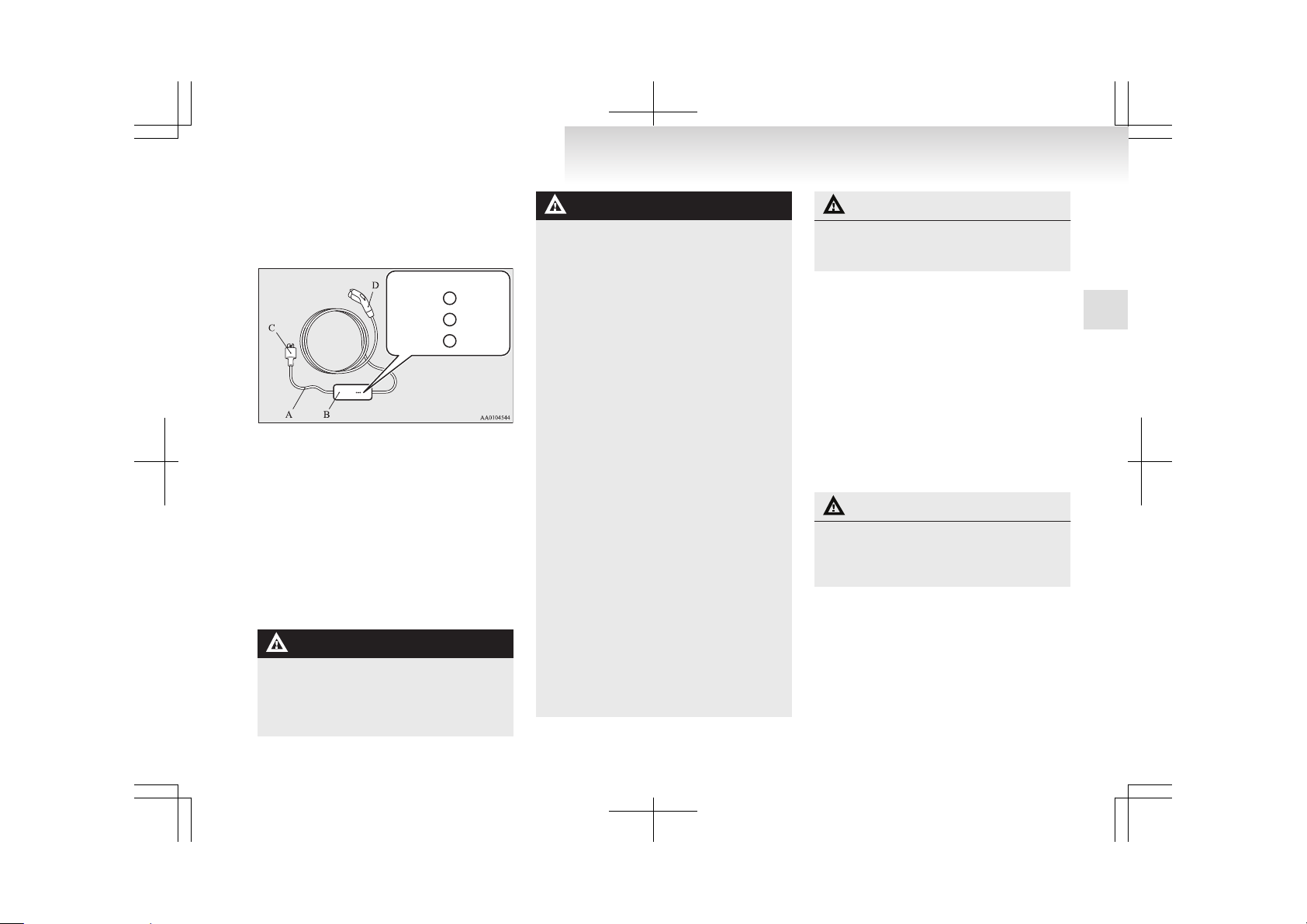
EV charging cable
E08301100024
Your vehicle is equipped with the EV charging cable (A) with control box (B).
Indicator (LED)
(Green)
(Orange)
(Red)
READY
CHARGE
FAULT
The indicator illuminates/blinks in the following
conditions.
l
Green: The charging cable plug (C) is inserted into an outlet and the electrical power is
provided correctly.
l
Orange: The regular charging plug (D) is connected and started charging correctly after
the green indicator is illuminated.
l
Red (illuminating): A problem is detected in
the control box.
l
Red (blinking): Electrical leakage or malfunction in the i- MiEV is detected.
WARNING
l
If the green or orange indicator does not
illuminate or the red indicator blinks or illuminates during regular charging,
please contact a MITSUBISHI MOTORS
Authorized Service Point.
WARNING
l
Do not charge with the EV charging cable banded or rolled.
The cable may be heated and resulting in
fire.
l
Do not alter or disassemble the EV charging cable. Doing so could cause fire, an
electric shock or injury.
l
Be sure to install the cap to the regular
charging plug and store the EV charging
cable at a place where the cable is not exposed to water or dust. Entry of foreign
matter such as water or dust at the metal
terminal of the regular charging plug or
charging cable plug may cause fire or malfunction. Contact with metal such as wire
or tool may cause fire, an electric shock
or malfunction.
l
If the EV charging cable, regular charging plug, charging cable plug or outlet
shows damage, corrosion or rust, or if loosening is found at the connection, do not
perform charging. Doing so could cause
fire, an electric shock, or short circuit.
l
Pay attention to the following for handling the EV charging cable.
Damage to the cable could cause fire, an
electric shock, or short circuit.
• Do not pull with undue force.
• Do not twist.
• Do not drag.
• Do not put an object on top.
• Do not put the cable close to a heating
unit including heater.
• Do not drop the regular charging plug
or do not give strong impact to it.
CAUTION
l
Do not charge with the outlet that is smaller than the current value described on
the control box.
NOTE
l
All indicators are illuminated momentarily
for confirming operation when the charging
cable plug is inserted into an outlet. After
that the green indicator is continuously illuminated.
l
The orange indicator will go off when the
charging is completed. The green indicator is
continuously illuminated while the charging
plug is inserted into an outlet.
Handling and storing the control box
E08301200025
CAUTION
l
While charging, it must be prevented being damaged to the control box by the attached rope as shown in the following illustration.
NOTE
l
Use the hook with load capacity over 4 kg,
that weight is the EV charging cable.
l
Check the rope has no damage or no loose before use.
Charging
1-03
1
Page 23
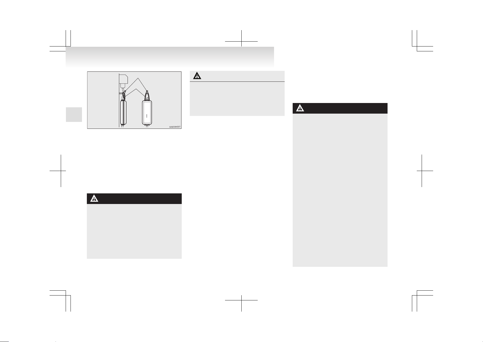
Hook
Rope
Cleaning the EV charging cable
E08301300026
1. Gently wipe off with gauze or other soft
cloth soaked with a 3 % aqueous solution of
neutral detergent.
2. Wipe off all the detergent with a soft cloth
dipped in fresh water and thoroughly wrung
out.
3. Wipe all moisture off and dry in a shaded,
well-ventilated area.
WARNING
l
In cleaning, be sure to remove the charging cable plug and the regular charging
plug from the outlet. Do not connect or
disconnect the plug with wet hand. Doing
so could cause an electric shock.
l
Do not have the metal terminal of the regular charging plug and the charging cable plug be exposed to water or neutral detergent. Operation with water could
cause fire or an electric shock.
CAUTION
l
Never use benzine, petrol, or other organic solvents, or acid or alkaline solvents. Doing so could cause deformation, discolour, or malfunction. Also, these substances may be present in various cleaners, so
check carefully before use.
Regular charging (charging
method with rated AC 220-240 V
outlet)
E08300900012
WARNING
l
Persons who use electro-medical apparatus such as implantable cardiac pacemaker or implantable cardioverter- defibrillator must check effect from charging with
the manufacturer of electro-medical apparatus. Electro-medical apparatus operations could be affected by charging.
l
Do not charge with the EV charging cable banded or rolled.
Doing so the cable may be heated and this
might result in fire.
l
Before charging, make sure that there is
no foreign matter such as dust at the regular charging connection and the regular
charging plug.
At this time, do not touch the regular
charging connection.
l
When the regular charging plug is connected to the charging connection, prevent
foreign matter such as water or dust
from entering in the connection.
Connection with foreign matter such as
water or dust may cause fire or an electric shock. Do not perform charging if
there might be strong exposure to water
at the connection.
l
Please observe the following in order to
prevent accidents during charging such
as electrocution.
Charging
1-04
1
Page 24
WARNING
• Make sure to use the EV charging cable that comes with the vehicle.
• Do not charge another vehicle using
the attached EV charging cable.
Doing so the cable may be heated and
this might result in fire.
• Make sure to use an outlet that is protected from water entering.
• Do not perform charging with the
body cover.
• Do not remove and insert plugs with
wet hands.
• Do not charge the battery if there is a
risk of lightning.
l
If abnormal smells are detected or the vehicle produces smoke, quickly stop charging.
l
Do not perform charging at a poorly ventilated place with surroundings covered.
Keep sparks, cigarettes, and flames away
from the auxiliary battery.
Flammable gas generated from the auxiliary battery in charging may be filled in a
building, resulting in explosion.
If charging is inevitably required, ventilate the area well.
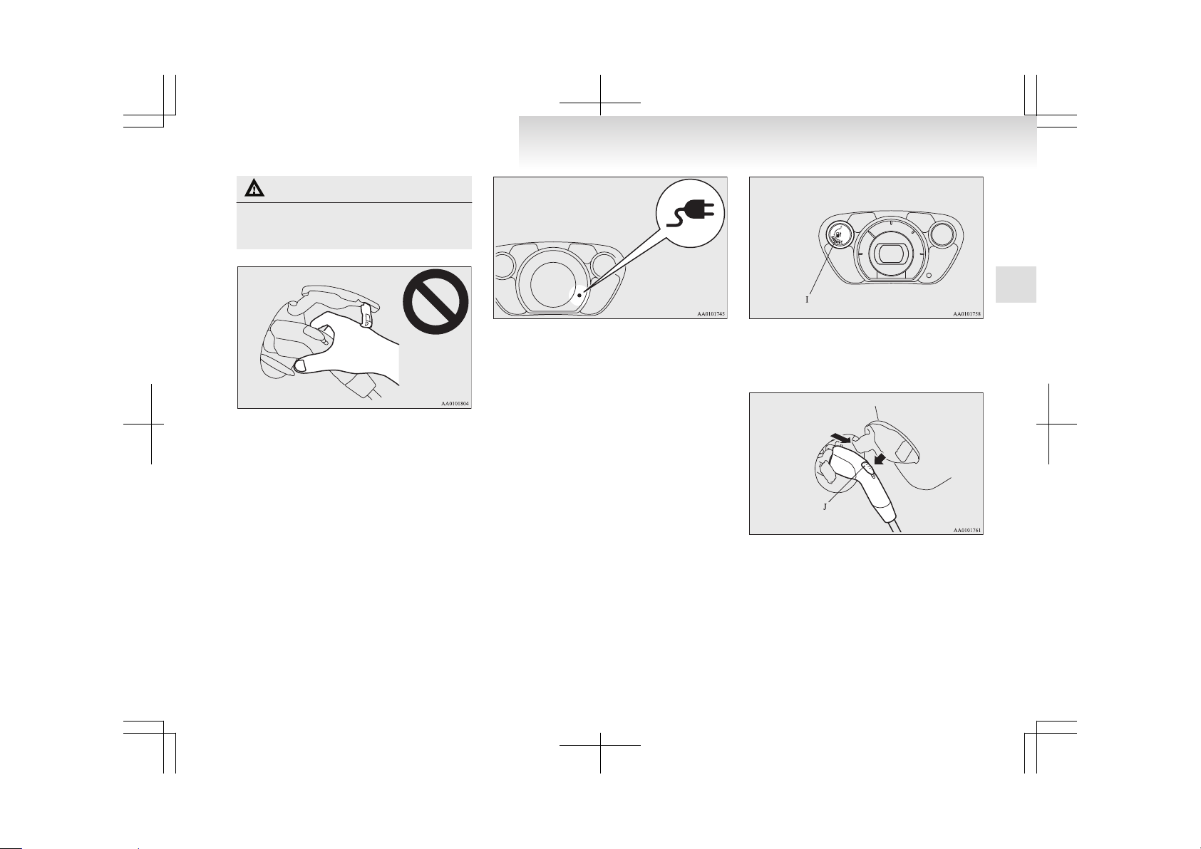
l
Grasp the regular charging plug when
connecting or disconnecting the EV charging cable.
Grasping the cable could cause an electric shock, short circuit, and/or fire.
CAUTION
l
Do not perform charging from other power source like a generator. Doing so could
cause a malfunction.
l
During charging, the cooling fans inside
the bonnet room may automatically be operated even if the electric motor switch is
in the “LOCK” position.
Keep your hands away from the cooling
fan during charging.
NOTE
l
The on board charger is only for rated AC
220-240 V outlets.
l
When connecting or disconnecting the regular charging plug, insert/pull out the plug
straight.
Also, do not incline or twist the plug.
Doing so could cause a bad connection or malfunction.
l
Make sure to lock the doors to prevent theft,
etc. during charging.
Charging from rated AC 220-240 V outlet
E08301000023
1. Fully apply the parking brake and place the
selector lever to the “P” (PARK) position.
2. Stop the electric devices such as lamps and
turn the electric motor switch to the “LOCK”
position.
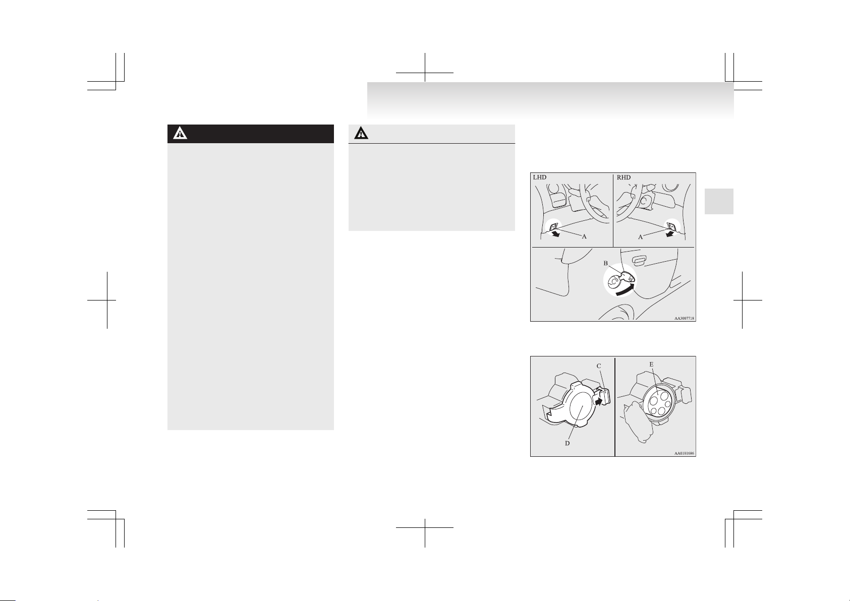
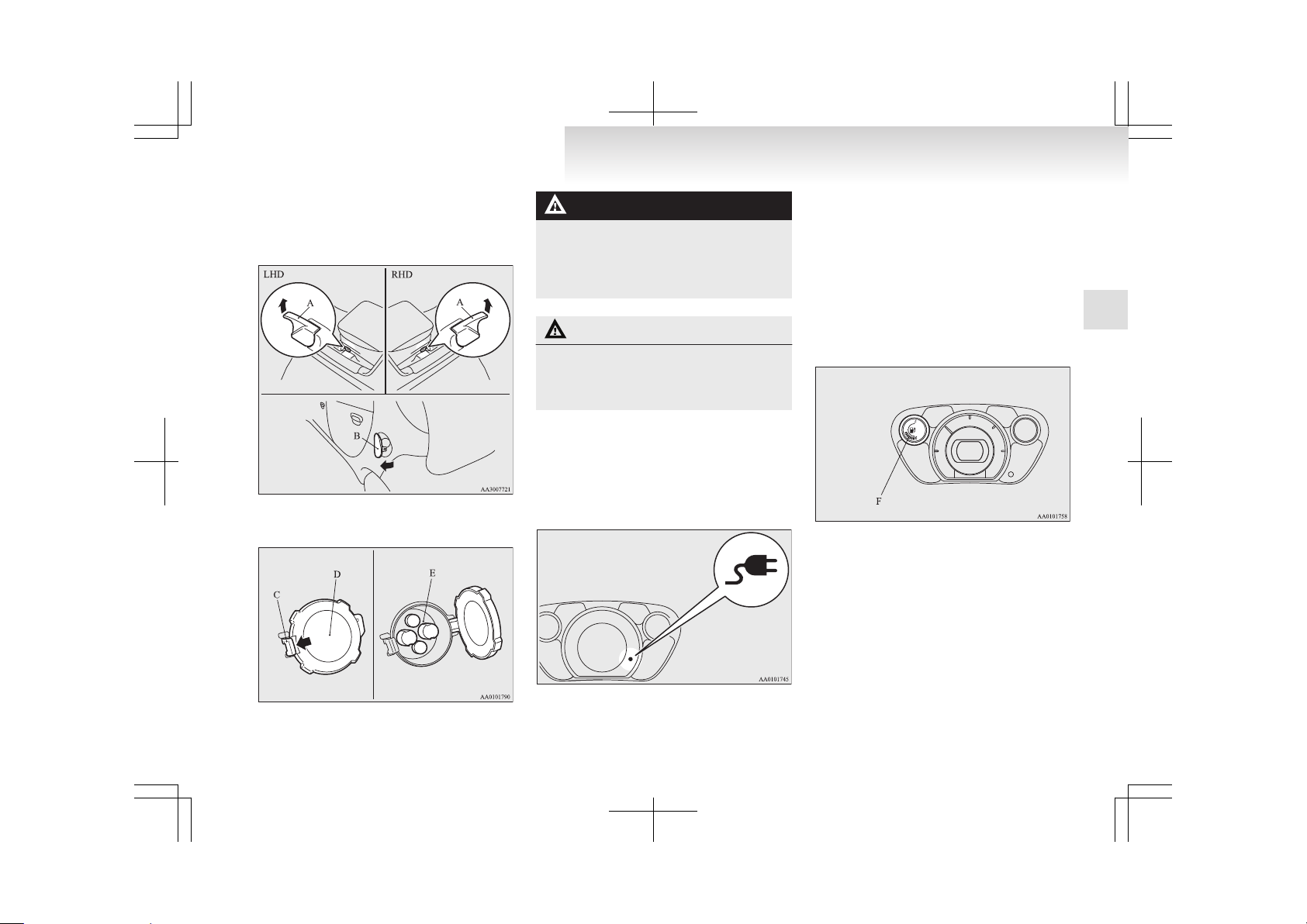
3. Pull the regular charging opener (A) at the
bottom left/right of the instrument panel to
open the regular charging lid (B) at the right
rear side of the vehicle.
4. Press the tab (C) to open the inner lid (D).
Charging
1-05
1
Page 25
WARNING
l
Do not touch the metal terminal of the regular charging connection (E) and the regular charging plug.
Doing so could cause an electric shock and/
or malfunction.
CAUTION
l
Do not leave for a long time with the inner lid opened. It becomes impossible to
charge if foreign material enters the regular charging connection.
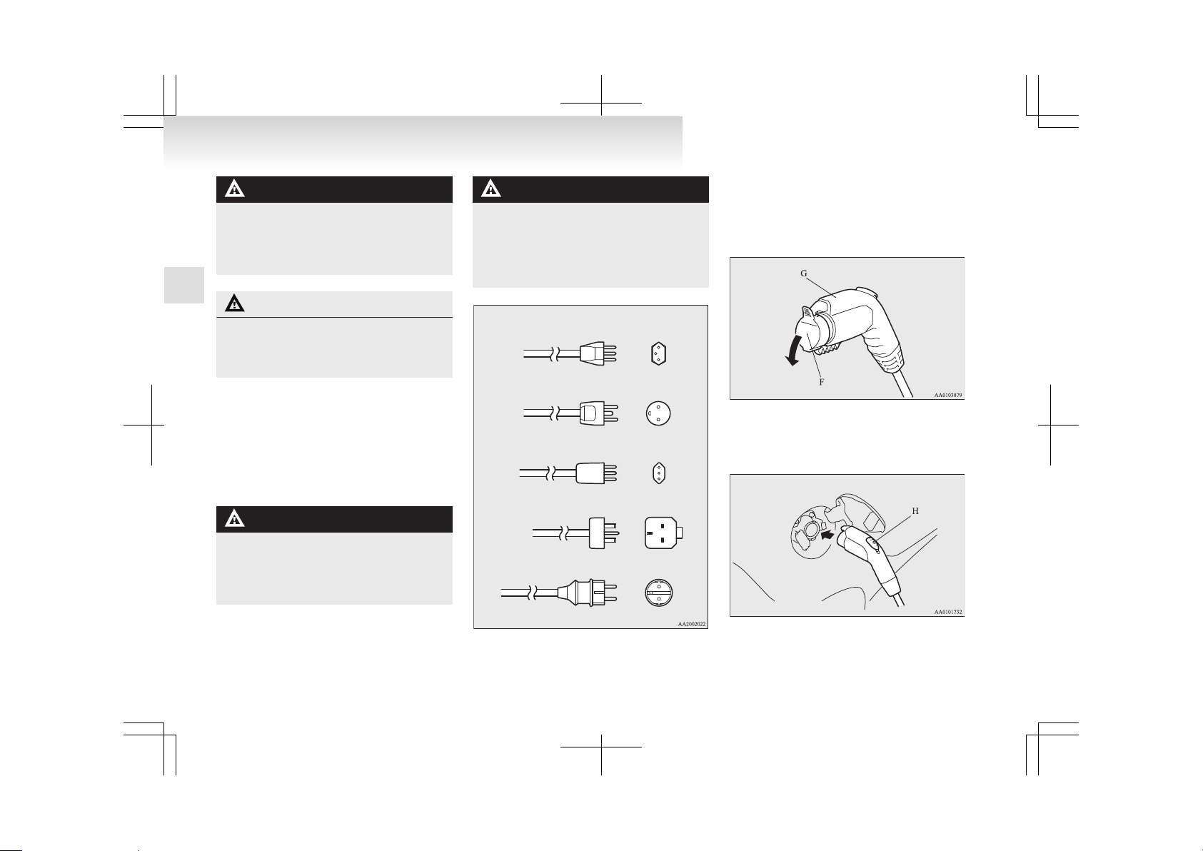
5. Insert the charging cable plug into an outlet.
NOTE
l
The shape of the charging cable plug and outlet may differ from country to country as
shown in the illustration.
l
Use the following outlets.
WARNING
l
To prevent an electric shock or fire due
to electric leak, perform charging using
the waterproofed outlet with earthing
which is connected to the ground fault interrupter.
WARNING
l
Use the rated AC 220-240 V outlet individually.
If a plug adapter is connected at the end
of the EV charging cable for use together
with other device, the outlet may be overheated, resulting in a fire.
Switzerland 250 V/10 A
Denmark 250 V/10 A
Italy 250 V/10 A
UK, Ireland 250 V/13 A
Germany, Spain, France, Sweden, etc. 250 V/16 A
6. Remove the cap (F) on the regular charging
plug (G) and make sure that there is no foreign matter such as dust at the end of the regular charging plug and the regular charging
connection.
7. Connect the regular charging plug until a
click sound is heard without pressing the button (H).
Charging
1-06
1
Page 26
CAUTION
l
Do not clasp the top of regular charging
plug. It could cause injury to touch the
protrusion on the lid.
NOTE
l
If the electric motor switch is turned to the
“START” position with the regular charging
plug connected to the regular charging connection, the electric motor unit cannot be started.
8. Make sure that the charging indicator on the
instrument cluster is illuminated.
If the charging indicator is not illuminated,
charging is not started.
Make sure that the regular charging connection and the plug are appropriately connected, and perform charging from Step 5 again.
NOTE
l
When the regular charging plug is connected
to the charging connection, the charging indicator is blinking. When charging is started,
the charging indicator is illuminated.
l
The charge level for traction battery can be
checked with the energy level gauge (I) on
the instrument cluster.
Refer to “Energy level gauge” on page 4-06.
9. Charging is complete when the charging indicator turns off. Pull out the regular charging
plug while pressing the button (J).
NOTE
l
Charging can be stopped half way. In this
case, also, pull out the regular charging plug
while pressing the button.
10. Close the inner lid and close the regular charging lid.
Charging
1-07
1
Page 27
NOTE
l
Make sure that the inner lid is completely
closed.
If the regular charging lid is forcibly closed
without completely closing the inner lid, the
hinge on the inner lid may be broken.
11. Remove the charging cable plug from the outlet.
12. Install the cap on the regular charging plug.
WARNING
l
After charging, be sure to close the inner
lid and the regular charging lid completely.
Be careful that water or dust does not enter in the regular charging connection, inner lid and regular charging plug.
Entry of water or dust could cause electric leakage, resulting in a fire or electric
shock.
l
After charging, be sure to disconnect the
plug from the outlet.
If the plug is left connected to the outlet,
immersion in water or tampering may
cause leakage or an electric shock.
Quick charging (charging
method with quick charger)
E08301400027
WARNING
l
Be sure to use the quick charger compatible with i-MiEV.
Use of a non-compatible quick charger
may cause fire or malfunction.
For the quick charger compatible with
i-MiEV, consult a MITSUBISHI
MOTORS Authorized Service Point.
l
For operation of quick chargers, follow
the manual of each quick charger.
l
Persons who use electro-medical apparatus such as implantable cardiac pacemaker or implantable cardioverter- defibrillator must check effect from charging with
the manufacturer of electro-medical apparatus. Electro-medical apparatus operations could be affected by charging.
l
Before charging, make sure that there is
no foreign matter such as dust at the
quick charging connection and the quick
charging plug.
At this time, do not touch the quick charging connection.
WARNING
l
When the quick charging plug is connected to the quick charging connection, prevent foreign matter such as water or dust
from entering in the connection.
Connection with foreign matter such as
water or dust may cause fire or an electric shock. Do not perform charging if
there might be strong exposure to water
at the connection.
CAUTION
l
During charging, the cooling fans inside
the bonnet room may automatically be operated even if the electric motor switch is
in the “LOCK” position.
Keep your hands away from the cooling
fan during charging.
NOTE
l
Make sure to lock the doors to prevent theft,
etc. during charging.
1. Fully apply the parking brake and move the
selector lever to the “P” (PARK) position.
2. Stop the electric devices such as lamps, air
conditioning, etc. and turn the electric motor
switch to the “LOCK” position.
Charging
1-08
1
Page 28
3. Pull the quick charging lid opener (A) at the
bottom left/right of the driver’s seat to open
the quick charging lid (B) at the left rear side
of the vehicle.
4. Press the tab (C) to open the inner lid (D).
WARNING
l
Do not touch the metal terminal of the
quick charging connection (E) and the
quick charging plug.
Doing so could cause an electric shock and/
or malfunction.
CAUTION
l
Do not leave for a long time with the inner lid opened. It becomes impossible to
charge if foreign material enters the
quick charging connection.
5. Connect the quick charging plug in the quick
charging connection to begin charging.
For connecting and disconnecting, follow the
instruction manual for each quick charger.
6. Make sure that the charging indicator on the
instrument cluster is illuminated.
If the charging indicator is not illuminated,
charging is not started.
Follow the manual of each quick charger.
NOTE
l
When the regular charging plug is connected
to the charging connection, the charging indicator is blinking. When charging is started,
the charging indicator is illuminated.
l
The charge level for traction battery can be
checked with the energy level gauge (F) on
the instrument cluster.
Refer to “Energy level gauge” on page 4-06.
l
Operation noise may be heard from the vehicle body during quick charging.
This noise comes from operation of the
traction battery cooling system, and it is
not a malfunction.
l
Since the traction battery cooling system
uses cool air of the air conditioning, the
air conditioning is automatically operated.
After quick charging, if the area under
the vehicle is wet, transparent and loose,
it is dehumidified water from the air conditioning and not a malfunction.
Charging
1-09
1
Page 29

7. Charging is complete when the charging indicator turns off.
Disconnect the quick charging plug according to the manual of the quick charger.
CAUTION
l
Do not leave the quick charging plug connected to the quick charging connection
after charging.
Doing so, someone might stumble and it
could cause an injury or the quick charging connection might be damaged by playing it.
8. Close the inner lid and close the quick charging lid.
WARNING
l
After charging, be sure to close the inner
lid and the quick charging lid completely.
Be careful that water or dust does not enter in the quick charging connection, inner lid and quick charging plug.
Entry of water or dust could cause fire,
electric shock or short circuit.
NOTE
l
If the electric motor switch is turned to the
“START” position with the quick charging
plug connected to the quick charging connection, the electric motor unit cannot be started.
Be sure to disconnect the quick charging
plug before start.
l
Charging may be completed before full
charge. This is a control for efficient charge
and not a malfunction.
To achieve full charge, repeat charging from
Step 5 again.
l
Make sure that the inner lid is completely
closed.
If the quick charging lid is forcibly closed
without completely closing the inner lid, the
hinge on the inner lid may be broken.
Charging
1-10
1
Page 30
Keys..............................................................................................2-02
Electronic immobilizer (Anti-theft starting system).....................2-02
Keyless entry system....................................................................2-03
Doors............................................................................................2-05
Central door locks.........................................................................2-06
“Child-protection” rear doors.......................................................2-07
Tailgate.........................................................................................2-08
Electric window control................................................................2-09
Locking and unlocking
2
Page 31

Keys
E00300102399
Two keys are provided. The key fits all locks.
Keep one in a safe place as a spare key.
WARNING
l
When taking a key on flights, do not
press any switches on the key while on
the plane. If a switch is pressed on the
plane, the key emits electromagnetic
waves, which could adversely affect the
plane’s flight operation.
When carrying a key in a bag, be careful
that no switches on the key can be easily
pressed by mistake.
NOTE
l
The key number is stamped on the tag as indicated in the illustration.
Make a record of the key number and store
the key and key number tag in separate places, so that you can order a key in the event
the original keys are lost.
l
The key is a precision electronic device with
a built-in signal transmitter. Please observe
the following in order to prevent malfunctioning.
• Do not leave the key anywhere where exposed to direct sunlight, for example on
the dashboard.
• Do not disassemble or modify.
• Do not excessively bend the key or subject it to strong impacts.
• Do not expose to water.
• Keep away from magnetic key rings.
• Keep away from audio systems, personal
computers, TVs, and other equipment
that generates a magnetic field.
• Keep away from devices that emit strong
electromagnetic waves, such as cellular
phones, wireless devices and high frequency equipment (including medical devices).
• Do not clean with ultrasonic cleaners or
similar equipment.
• Do not leave the key where it may be exposed to high temperature or high humidity.
l
The electric motor unit is designed so that it
will not start if the ID code registered in the
immobilizer computer and the key’s ID code
do not match. Refer to the “Electronic immobilizer” section for details and key usage.
Electronic immobilizer (Anti-
theft starting system)
E00300201928
The electronic immobilizer is designed to significantly reduce the possibility of vehicle theft. The
purpose of the system is to immobilize the vehicle
if an invalid start is attempted. A valid start attempt
can only be achieved by using a key “registered” to
the immobilizer system.
NOTE
l
In the following cases, the vehicle may not
be able to receive the registered ID code
from the registered key and the electric motor unit may not start.
• When the key contacts a key ring or other
metallic or magnetic object (Type A)
• When the key grip contacts metal of another key (Type B)
Locking and unlocking
2-02
2
Page 32

• When the key contacts or is close to other
immobilizing keys (including keys of other vehicles) (Type C)
In cases like these, remove the object or
additional key from the vehicle key and
turn the key back to the “ACC” or
“LOCK” position. Then try again to start
the electric motor unit. If the electric motor unit does not start, we recommend
you to contact your MITSUBISHI
MOTORS Authorized Service Point.
l
Two keys are provided.
If you lose one of them, order a key from
your MITSUBISHI MOTORS Authorized
Service Point as soon as possible.
To obtain a replacement or extra spare key,
take your vehicle and any remaining key to
your MITSUBISHI MOTORS Authorized
Service Point. All the keys have to be registered in the immobilizer computer unit. The
immobilizer can register up to 8 different keys.
CAUTION
l
Don’t make any alterations or additions
to the immobilizer system; alterations or
additions could cause failure of the immobilizer.
Keyless entry system
E00300302434
Press the remote control switch, and all doors and
the tailgate will be locked or unlocked as desired.
1- LOCK switch
2- UNLOCK switch
3- Indication lamp
To lock
Press the LOCK switch (1), and all doors and the
tailgate will be locked. When they are locked with
the room lamp at the middle (•) position or at the
“DOOR” position, the room lamp and the turn-signal lamps blink once.
To unlock
Press the UNLOCK switch (2), and all doors and
the tailgate will be unlocked. When unlocked with
the room lamp at the (•) position or at the “DOOR”
position, the room lamp will be turned on for approximately 15 seconds and the turn-signal lamps
will blink twice.
Locking and unlocking
2-03
2
Page 33

NOTE
l
The indication lamp (3) comes on each time
a switch is pressed.
l
If the UNLOCK switch (2) is pressed and
any of the doors or the tailgate is not opened
within approximately 30 seconds, relocking
will automatically occur.
l
It is possible to modify functions as follows:
For further information, please contact your
MITSUBISHI MOTORS Authorized Service
Point.
• The time for automatic relocking can be
changed.
• The confirmation function (flashing of
the turn-signal lamps) can be set to operate only when the doors and the tailgate
are locked or only when the doors and
the tailgate are unlocked.
• The confirmation function (this indicates
locking or unlocking of the doors and the
tailgate with the flash of the turn-signal
lamps) can be deactivated.
• The number of times the turn-signal
lamps are flashed by the confirmation
function can be changed.
l
The keyless entry system does not operate in
the following conditions:
• The key is left in the key cylinder.
• The door or the tailgate is open.
l
The remote control switch will operate within approximately 4 m from the vehicle. However, the operating range of the remote control switch may change if the vehicle is located near a power station, or radio/TV broadcasting station.
l
If either of the following problems occurs,
the battery may be exhausted.
• The remote control switch is operated at
the correct distance from the vehicle, but
the doors and the tailgate are not locked/
unlocked in response.
• The indication lamp (3) is dim or does
not come on.
For further information, please contact
your MITSUBISHI MOTORS Authorized Service Point.
If you replace the battery yourself, refer
to “Procedure for replacing the remote
control switch battery” on page 2-04.
l
If your remote control switch is lost or damaged, please contact your MITSUBISHI
MOTORS Authorized Service Point for a replacement remote control switch.
l
If you wish to add a remote control switch,
we recommend you to contact a
MITSUBISHI MOTORS Authorized Service
Point.
A maximum of 4 remote control switches are
available for your vehicle.
Operation of the outside rear-view mirrors
E00310800119
To fold
Within 30 seconds of locking the doors and the tailgate using the LOCK switch (1), press the LOCK
switch twice rapidly to fold the outside rear-view
mirrors.
To extend
Within 30 seconds of unlocking the doors and the
tailgate using the UNLOCK switch (2), press the
UNLOCK switch twice rapidly to return the outside rear-view mirrors to their extended positions.
Procedure for replacing the remote control switch battery
E00309500129
1. Before replacing the battery, remove static
electricity from your body by touching a metal part such as doorknob of the room.
2. Remove the screw (A) from the remote control switch.
3. With the MITSUBISHI mark facing you, insert the clothcovered tip of a straight blade
(or minus) screwdriver into the notch in the
remote control switch case and use it to open
the case.
Locking and unlocking
2-04
2
Page 34

NOTE
l
Be sure to perform the procedure with the
MITSUBISHI mark facing you. If the
MITSUBISHI mark is not facing you when
you open the remote control switch case, the
switches may come out.
4. Remove the remote control transmitter from
the remote control switch case. Then, open
the remote control transmitter using the method described in step 2.
5. Remove the old battery.
6. Install a new battery with the + side (B) down.
Coin type battery
CR1616
- side
+ side
7. Close the remote control transmitter firmly.
8. Place the remote control transmitter in the remote control switch case, then securely close
the remote control switch case.
9. Attach the screw (A) removed in step 1.
10. Check the keyless entry system to see that it
works.
NOTE
l
You may purchase a replacement battery at
an electric appliance store.
l
A MITSUBISHI MOTORS Authorized Service Point can replace the battery for you if
you prefer.
CAUTION
l
When the remote control switch case is
opened, be careful to keep water, dust,
etc. out. Also, do not touch the internal
components.
Doors
E00300402187
CAUTION
l
Make sure the doors are closed: driving
with doors not completely closed is dangerous.
l
Never leave children in the vehicle unattended.
l
Be careful not to lock the doors while the
key is inside the vehicle.
NOTE
l
To prevent the key from being locked inside
the vehicle, neither the lock knob on the driver’s door nor the key can be used to lock the
driver’s door when it is open.
To lock or unlock with the key
1- Lock
2- Unlock
Locking and unlocking
2-05
2
Page 35

To lock or unlock from inside the vehicle
1- Lock
2- Unlock
Pull the inside door handle towards you to open the
door.
NOTE
l
The driver’s door can be opened without using the lock knob by pulling on the inside
door handle.
Also, all other doors and the tailgate are unlocked at the same time.
To lock without using the key
Set the inside lock knob (1) to the locked position,
and close the door (2).
NOTE
l
The driver’s door cannot be locked using the
inside lock knob while the driver’s door is
opened.
Central door locks
E00300801852
NOTE
l
Each of the doors can be locked or unlocked
independently by using the inside lock knob.
l
Repeated continuous operation between lock
and unlock could activate the central door
locking systems built-in protection circuit
and prevent the system from operating. If
this occurs, wait about 1 minute before operating the inside lock knob or the key.
Driver’s door with key
Using the key on the driver’s door locks or unlocks
all doors and the tailgate.
1- Lock
2- Unlock
Locking and unlocking
2-06
2
Page 36

Driver’s door with inside lock knob
Using the inside lock knob on the driver’s door
locks or unlocks all doors and the tailgate.
1- Lock
2- Unlock
Unlocking doors using selector lever
It is possible to unlock all doors and the tailgate using the selector lever by placing it in the “P” position while the electric motor switch is in the “ON”
position.
NOTE
l
The vehicle is shipped from the factory with
a setting established such that the doors and
the tailgate are not unlocked when the selector lever is placed in the “P” position with
the electric motor switch in the “ON” position. If you wish to change the setting such
that the doors and the tailgate are unlocked,
contact your MITSUBISHI MOTORS Authorized Service Point.
“Child-protection” rear doors
E00300901026
1- Lock
2- Unlock
Child protection helps prevent the rear doors from
being opened accidentally from the inside.
If the lever is set to the locked position, the rear
door cannot be opened using the inside handle, but
only with the outside handle.
If the lever is set to the “Unlock” position, the
child protection mechanism does not function.
CAUTION
l
When driving with a child in the rear
seat, please use the child protection to prevent accidental door opening which may
cause an accident.
Locking and unlocking
2-07
2
Page 37

Tailgate
E00301401161
WARNING
l
When opening and closing the tailgate,
make sure that there are no people nearby and be careful not to hit your head or
pinch your hands, neck, etc.
To open
After unlocking the tailgate, push the switch (A)
and pull up the tailgate.
NOTE
l
If you do not open the tailgate immediately
after pulling the handle, the tailgate cannot
be lifted. If this happens, pull the handle
again and lift the tailgate.
l
The tailgate cannot be opened when the battery is flat or disconnected.
To close
Pull the tailgate grip (A) downward as illustrated.
Gently push the upper gate from the outside with
enough force so that it is completely closed. Always ensure the tailgate is securely closed.
CAUTION
l
When closing the tailgate, always ensure
your or other person’s fingers cannot be
caught by the tailgate.
NOTE
l
Gas struts (B) are installed to support the tailgate.
To prevent damage or faulty operation.
• Do not hold the gas struts when closing
the tailgate.
• Also, do not push or pull the gas struts.
• Do not attach any plastic material, tape,
etc., to the gas struts.
• Do not tie string, etc., around the gas struts.
• Do not hang any object on the gas struts.
Locking and unlocking
2-08
2
Page 38

Electric window control
E00302200550
The electric windows can only be operated with the
electric motor switch in the “ON” position.
WARNING
l
Before operating the electric window control, make sure that nothing can get trapped (head, hand, finger, etc.).
l
Never leave the vehicle without removing
the key.
l
Never leave a child (or other person who
might not be capable of safe operation of
the electric window control) in the vehicle
alone.
l
The child may tamper with the switch at
the risk of its hands or head being trapped in the window.
Electric window control switch
E00302301705
Each window opens or closes while the corresponding switch is operated.
Driver’s switch (LHD)
Driver’s switch (RHD)
1- Driver’s door window
2- Front passenger’s door window
3- Rear left door window
4- Rear right door window
5- Lock switch
Driver’s switches
The driver’s switches can be used to operate all
door windows.
A window can be opened or closed by operating
the corresponding switch.
Press the switch down to open the window, and
pull up the switch to close it.
If the switch for the driver’s door window is fully
pressed down, the door window automatically
opens completely.
If you want to stop the door window movement,
pull up the switch.
Passenger’s switches
The passenger’s switches can be used to operate
the corresponding passenger’s door windows.
Press the switch down for opening the door window, and pull up the switch for closing.
NOTE
l
Repeated operation with the electric motor
unit stopped will run down the battery. Operate the window switches only while the electric motor unit is running.
Lock switch
E00303101188
When this switch is operated, the passenger’s
switches cannot be used to open or close the windows and the driver’s switch cannot open or close
any windows other than the driver’s window.
Locking and unlocking
2-09
2
Page 39

To unlock, press it once again.
1- Lock
2- Unlock
WARNING
l
A child may tamper with the switch at
the risk of its hands or head being trapped in the window. When driving with a
child in the vehicle, please press the window lock switch to disable the passenger’s switches.
Timer function
E00302400927
The door windows can be opened or closed for 30
seconds after the electric motor switch is turned
from the “ON” position to the “ACC” or “LOCK”
position.
However, once the driver’s door or the front passenger’s door is opened, the windows cannot be operated.
Locking and unlocking
2-10
2
Page 40

Seat...............................................................................................3-02
Seat adjustment.............................................................................3-03
Front seat......................................................................................3-03
Rear seat.......................................................................................3-05
Head restraints..............................................................................3-07
Seat belts.......................................................................................3-08
Pregnant women restraint.............................................................3-10
Seat belt pretensioner system and force limiter system................3-11
Child restraint...............................................................................3-11
Seat belt inspection.......................................................................3-20
Supplemental restraint system (SRS) - airbag..............................3-20
Seat and seat belts
3
Page 41

Seat
E00400101869
1-Front seat
l
To adjust forward or backward ® p. 3-03
l
To recline the seatback ® p. 3-04
l
To adjust seat height (driver’s seat only) ® p. 3-04
l
Heated seat (driver’s seat only)* ® p. 3-04
2-Rear seat
l
To recline the seatback ® p. 3-05
l
Folding the seatbacks forward ® p. 3-06
Seat and seat belts
3-02
3
Page 42

Seat adjustment
E00400300633
Adjust the driver’s seat so that you are comfortable
and that you can reach the pedals, steering wheel,
switches etc. while retaining a clear field of vision.
WARNING
l
Do not attempt to adjust the seat while
driving. This can cause loss of vehicle control and result in an accident. After adjustments are made, ensure the seating is
locked in position by attempting to move
the seat forward and rearward without using the adjusting mechanism.
l
Do not allow people or children to ride in
any area of your vehicle that is not equipped with seats and seat belts, and make
sure that everyone travelling in your vehicle is in a seat and wearing a seat belt, or
in the case of a child is strapped in a child
restraint.
l
To minimize the risk of personal injury
in the event of a collision or sudden braking, the seatbacks should always be in the
almost upright position while the vehicle
is in motion. The protection provided by
the seat belts may be reduced significantly when the seatback is reclined. There is
greater risk that the passenger will slide
under the seat belt, resulting in serious injury, when the seatback is reclined.
CAUTION
l
Make sure the seat is adjusted by an
adult or with adult supervision for correct and safe operation.
l
Do not place a cushion or the like between your back and the seatback while
driving. The effectiveness of the head restraints will be reduced in the event of an
accident.
l
When sliding the seats, be careful not to
catch your hand or foot.
Front seat
E00400400197
To adjust forward or backward
E00400500794
Pull the seat adjusting lever and adjust the seat forward or backward to the desired position, and release the adjusting lever.
WARNING
l
To ensure the seat is locked securely, try
to move the seat forward or backward
without using the adjusting lever.
Seat and seat belts
3-03
3
Page 43

To recline the seatback
E00400601008
In order to recline the seatback, lean forward slightly, pull the seatback lock lever up, and then lean
backward to the desired position and release the lever. The seatback will lock in that position.
CAUTION
l
The reclining mechanism of the seatback
is spring loaded, causing it to return to
the vertical position when the lock lever
is operated. When using the lever, sit
close to the seatback or hold it with your
hand to control its return motion.
To adjust seat height (driver’s seat only)
E00400701054
To adjust the seat height, operate the lever repeatedly.
1- Raise
2- Lower
Heated seat (driver’s seat only)*
E00401101013
The heated seat can be operated with the electric
motor switch in the “ON” position. Operate the
switch as indicated by arrows. The indication lamp
(A) will illuminate while the heater is on.
1- Heater on.
2- Heater off.
CAUTION
l
Switch off the seat heater when not in use.
l
Continuous use while the ready indicator
is not illuminated can cause the auxiliary
battery to run down.
l
If the following types of persons use the
heated seat, they might become too hot or
receive minor burns (red skin, heat blisters, etc.):
• Elderly or ill people
• People with sensitive skin
• Excessively tired people
• People under the influence of sleep inducing medication, etc.
Seat and seat belts
3-04
3
Page 44

CAUTION
l
Do not place heavy objects on the seat or
stick pins, needles, or other pointed objects into it.
l
Do not use a blanket, cushion, or other material with high heat insulation properties
on the seat while using the heater; this
might cause the heater element to overheat
l
Do not use benzine, kerosene, petrol, alcohol or other organic solvents when cleaning the seat. Doing so could damage not
only the seat cover, but also the heater element.
l
If water or any other liquid is spilled on
the seat, allow it to dry thoroughly before
attempting to use the heater.
l
Turn the heater off immediately if it appears to be malfunctioning during use.
Rear seat
E00401300353
WARNING
l
When a person sits in the rear seat, pull
up the head restraint to a height at which
it locks in position. Be sure to make this
adjustment before starting to drive. Serious injuries could otherwise be suffered
as the result of an impact. Refer to “Head
restraints” on page 3-07.
CAUTION
l
Child restraint lower anchorages (A) are
provided between the seat cushion and
the seatback.
Be careful that the lower anchorages may
be hot due to heat of the electric motor
unit room.
To recline the seatback
E00401500254
In order to recline the seatback, lean forward slightly, pull the lever, and then lean backward to the desired position and release the lever. The seatback
will lock in that position.
NOTE
l
It is possible to adjust the seatback angle independently on each side.
Seat and seat belts
3-05
3
Page 45

Folding the seatbacks forward
E00401600330
Larger objects can be loaded into the vehicle if a
seatback is folded forward.
CAUTION
l
Do not stack luggage in the vehicle higher
than the seatback height. Also, firmly secure the luggage.
Serious accidents could result due to unrestrained objects entering the passenger
compartment during sudden braking.
To fold
Pull the lever, and fold the rear seatbacks forward.
NOTE
l
Do not operate the lever in the wrong direction.
Doing so could damage the lever and make it
impossible to operate the seatback.
To replace
1. Raise the seatback until it locks securely into
place.
2. Push lightly on the seatback to confirm that
it has actually been secured.
Rear seat cushion
E00401900173
The rear seat cushion can be removed. It is removed when the tyre repair kit stored under the
seat cushion is taken out. Use this function when
putting the seat covers on, etc.
To remove
1. Pull the seat stoppers (A) to unlock the seat
cushion (B).
2. Lift up the seat cushion and pull it towards
you to remove it.
To install
1. Place the seat belt’s buckles on top of the
seat cushion.
2. Pushing the seat cushion as far back as possible, press the hooks (A) on the underside of
the seat cushion into the right and left stopper installation holes (B) until a click is heard.
3. After installing the seat cushion, shake it lightly to check that it is properly fixed in position.
Seat and seat belts
3-06
3
Page 46

Head restraints
E00403301497
WARNING
l
Driving without the head restraints in
place can cause you and your passengers
serious injury or death in an accident. To
reduce the risk of injury in an accident, always make sure the head restraints are installed and properly positioned when the
seat is occupied.
l
Never place a cushion or similar device
on the seatback. This can adversely affect
head restraint performance by increasing
the distance between your head and the
restraint.
To adjust height
Adjust the head restraint height so that the centre
of the head restraint is as close as possible to eye
level to reduce the chances of injury in the event of
collision. Any person too tall for the head restraint
to reach their seated eye level, should adjust the restraint as high as possible.
To raise the head restraint, move it upward. To lower the restraint, move it downward while pushing
the height adjusting knob (A) in the direction of the
arrow. After adjustment, push the head restraint
downward and make sure that it is locked.
To remove
Lift the head restraint with the height adjusting
knob (A) pushed in.
Installation
Confirm that they are facing the correct direction,
and then insert them into the seatback while pressing the height adjusting knob (A) in the direction indicated by the arrow.
CAUTION
l
Confirm that the height adjusting knob
(A) is correctly adjusted as shown in the
illustration, and also lift the head restraints to ensure that they do not come
out of the seatback.
CAUTION
l
The head restraints for the seats differ in
shape and size. When installing head restraints, make sure the head restraints
are fitted in their respective seats and do
not install the head restraints in the
wrong direction.
Seat and seat belts
3-07
3
Page 47

Seat belts
E00404800636
To protect you and your passengers in the event of
an accident, it is most important that the seat belts
be worn correctly while driving.
The front seat belts have a pretensioner system.
These belts are used the same way as a conventional seat belt.
Refer to “Seat belt pretensioner system and force
limiter system” on page 3-11
WARNING
l
Always place the shoulder belt over your
shoulder and across your chest. Never
put it behind you or under your arm.
l
One seat belt should be used by only one
person. Doing otherwise can be dangerous.
l
The seat belt will provide its wearer with
maximum protection if the recliner seatback is placed in fully upright position.
When the seatback is reclined, there is
greater risk that the passenger will slide
under the belt, especially in a forward impact accident, and may be injured by the
belt or by striking the instrument panel
or seatbacks.
l
Seat belts should always be worn by every adult who drives or rides in this vehicle, and by all children who are tall
enough to wear seat belts properly.
Other children should always use proper
child restraint systems.
l
Remove any twists when using the belt.
WARNING
l
No modifications or additions should be
made by the user which will either prevent the seat belt adjusting devices from
operating to remove slack, or prevent the
seat belt assembly from being adjusted to
remove slack.
l
Never hold a child in your arms or on
your lap when riding in this vehicle, even
if you are wearing your seat belt. To do
so risks severe or fatal injury to the child
in a collision or sudden stop.
l
Always adjust the belt to a snug fit.
l
Always wear the lap portion of the belt
over your hips.
3-point type seat belt (with emergency locking mechanism)
E00404901070
This type of belt requires no length adjustment.
Once worn, the belt adjusts itself to the movement
of the wearer, but in the event of a sudden or strong
shock, the belt automatically locks to hold the wearer’s body.
Seat and seat belts
3-08
3
Page 48

NOTE
l
You can check if the belt locks by pulling it
forward quickly.
To fasten
1. Pull the seat belt out slowly while holding
the latch plate.
NOTE
l
When the seat belts cannot be pulled out in a
locked condition, pull the belts once forcefully and then return them. After that, pull the
belts out slowly once again.
2. Insert the latch plate into the buckle until a
“click” is heard.
WARNING
l
Never wear the lap portion of the belt
across your abdomen. During accidents it
can press sharply against the abdomen
and increase the risk of injury.
WARNING
l
The seat belts must not be twisted when
worn.
3. Pull the belt slightly to adjust slackness as desired.
To unfasten
Hold the latch plate and push the button on the buckle.
NOTE
l
As the belt retracts automatically, keep holding the latch plate while retracting so that the
belt stows slowly. Failure to do this could
damage the vehicle.
Seat belt warning
E00413000025
Driver’s and front passenger’s seat belt reminder/ warning lamp
E00414800017
The driver’s and front passenger’s seat belt warning lamp is located on the instrument panel.
If the electric motor switch is turned to the “ON”
position without the driver’s or the front passenger’s seat belt being fastened, the warning lamp
will come on, and the tone will sound for approximately 6 seconds to remind the driver and front passenger to fasten the seat belt.
If the seat belt remains unfastened approximately 1
minute later, the warning lamp will flash and the
tone will sound intermittently for approximately 90
seconds when the vehicle is driven.
If the seat belt subsequently remains unfastened,
the warning lamp and tone will issue further warnings each time the vehicle starts moving from a
stop. And if the passenger unfastens the seat belt
while driving, the warning will operate in the same
way.
When the seat belt is fastened, the warnings will stop.
Seat and seat belts
3-09
3
Page 49

NOTE
l
For the front passenger seat, the warning function works only while a person is sitting on
the seat.
l
When luggage is placed on the front passenger seat, a sensor in the seat cushion may, depending on the weight and position of the luggage, cause the warning tone to sound and
the warning lamp to come on.
Rear passenger’s seat belt warning lamps
E00414900018
The rear passenger’s seat belt warning lamps are located on the instrument panel.
If the electric motor switch is turned to the “ON”
position while a seat belt is not fastened, the warning lamp comes on for approximately 30 seconds
to remind the rear passenger to fasten the seat belt.
If the vehicle is driven with the seat belt still unfastened, the warning lamp comes on for approximately another 30 seconds. (This illumination happens
only the first time the vehicle starts moving with
the seat belt still unfastened.)
The warning lamp goes off when the seat belt is fastened.
NOTE
l
The warning lamps come on even if no one
is sitting on the rear seat.
l
If a seat belt is unfastened while the vehicle
is being driven, the tone sounds for approximately 1 second and the warning lamp
comes on for approximately 30 seconds.
l
If the seat belts are initially fastened but a
seat belt is unfastened while the vehicle is stationary and the vehicle is then driven with
the seat belt still unfastened, the warning
lamp comes on again for approximately 30
seconds.
Pregnant women restraint
E00405600077
WARNING
l
Seat belts work for everyone, including
pregnant women. Pregnant women
should use the available seat belts. This
will reduce the likelihood of injury to
both the woman and the unborn child.
The lap belt should be worn across the
thighs and as snug against the hips as possible, but not across the waist. Consult
your doctor if you have any additional
questions or concerns.
Seat and seat belts
3-10
3
Page 50

Seat belt pretensioner system and
force limiter system
E00405700166
The driver’s seat and front passenger’s seat each
have a seat belt equipped with a pretensioner system.
Pretensioner system
E00405801164
The pretensioner system will retract its respective
seat belts instantaneously, thus maximizing the seat
belt’s effectiveness, if there is a frontal impact severe enough to injure the driver and/or front passenger and the electric motor switch is in the “ON” or
“START” position.
WARNING
l
To obtain the best results from your pretensioner seat belt, make sure you have adjusted your seat correctly and wear your
seat belt properly.
CAUTION
l
Installation of audio equipment or repairs in the vicinity of the pretensioner
seat belts or floor console must be performed in line with MITSUBISHI
MOTORS guidelines. It is important to
do so because the work could affect the
pretensioner systems.
CAUTION
l
If you need to scrap the vehicle, please consult a MITSUBISHI MOTORS Authorized Service Point. It is important to do
so because unexpected activation of the
pretensioner seat belts could cause injuries.
NOTE
l
The pretensioner seat belts will be activated
if the vehicle suffers a severe frontal impact,
even if the seat belts are not worn.
l
The pretensioner seat belts are designed to
work only once. After the pretensioner seat
belts have been activated, we recommend
you have them replaced by a MITSUBISHI
MOTORS Authorized Service Point.
SRS warning lamp
E00405900315
This warning lamp is shared by the SRS airbags
and the pretensioner seat belts. Refer to “SRS warning lamp” on page 3-29.
Force limiter system
E00406000209
In the event of a collision, each force limiter system will effectively absorb the load applied to the
seat belt to minimize the impact to the passenger.
Child restraint
E00406401747
When transporting children in your vehicle, some
type of child restraint system should always be
used according to the size of the child. This is required by law in most countries.
The regulations concerning driving with children in
the front seat may differ from country to country.
You are advised to comply with the relevant regulations.
WARNING
l
When possible, put children in the rear
seat. Accident statistics indicate that children of all sizes and ages are safer when
properly restrained in the rear seat rather than in the front seat.
l
Holding a child in your arms is no substitute for a restraint system. Failure to use
a proper restraint system can result in severe or fatal injury to the child.
l
Each child restraint device or fixing is to
be used only by one child.
Seat and seat belts
3-11
3
Page 51

Caution for installing the child restraint on vehicles with a front passenger airbag
E00406500318
The label shown here is attached on vehicles with a
front passenger airbag.
WARNING
l
Extreme Hazard!
Do not use a rearward facing child restraint on a seat protected by an airbag in
front of it!
Use rearward facing child restraints in the rear seat
or turn off the front passenger’s airbag ON-OFF
switch. (Refer to “To turn an airbag off” on page
3-23)
Front passenger’s airbag ON
WARNING
l
A REARWARD FACING CHILD RESTRAINT must NOT be used in the front
passenger seat if the front passenger’s airbag has not been deactivated. The force
of an inflating airbag could kill or cause
serious injuries to the child. A rearward
facing child restraint must only be used
in the rear seat.
l
A FORWARD FACING CHILD RESTRAINT should be used in the rear seat
whenever possible; if used in the front
seat, turn off the front passenger’s airbag
ON-OFF switch.
Infants and small children
E00406600999
When transporting infants and small children in
your vehicle, follow the instruction given below.
Instruction:
l
For small infants, an infant carrier should be
used. For small children whose height when
seated allows the shoulder belt to lie in contact with the face or the throat, a child seat
should be used.
l
The child restraint system should be appropriate for the child’s weight and height and properly fit in the vehicle. For a higher degree of
safety: THE CHILD RESTRAINT SYSTEM
SHOULD BE INSTALLED IN THE REAR
SEAT.
Seat and seat belts
3-12
3
Page 52

NOTE
l
Before purchasing a child restraint system,
try installing it in the rear seat to make sure
there is a good fit. Because of the location of
the seat belt buckles and the shape of the seat
cushion, it may be difficult to securely install
some manufacturer’s child restraint systems.
If the child restraint system can be pulled forward or to either side easily on the seat cushion after the seat belt has been tightened,
choose another manufacturer’s child restraint
system.
WARNING
l
When installing a child restraint system,
refer to the instructions provided by the
manufacturer of the restraint system. Failure to do so can result in severe or fatal
injury to the child.
l
After installation, push and pull the child
restraint system back and forth, and side
to side, to see that it is properly secured.
If the child restraint system is not installed securely, it may cause injury to the
child or other occupants in case of an accident or sudden stops.
l
When the child restraint system is not in
use, keep your child restraint system secured with the seat belt or remove it from
the vehicle in order to prevent it from being thrown around inside the vehicle during an accident.
Depending on the seating position in the vehicle and the child restraint system that you
have, the child restraint can be attached using one of the following two locations:
• To the lower anchorage in the rear seat
ONLY if the child restraint has ISOFIX
mountings (See page 3-18).
• To the seat belt (See page 3-19).
Older children
E00406700277
Children who have outgrown the child restraint system should be seated in the rear seat and wear combination lap shoulder belt.
The lap portion of the belt should be snug and positioned low on the abdomen so that it is below the
top of the hip-bone. Otherwise, the belt could intrude into the child’s abdomen during an accident
and cause injury.
Seat and seat belts
3-13
3
Page 53

Suitability for various ISOFIX positions
E00411400373
Mass group Size class Fixture
Vehicle ISOFIX positions
Rear (Left side/Right side)
Carrycot F ISO/L1 X
G ISO/L2 X
0 - Up to 10 kg
(0-9 months)
E ISO/R1 X
0+ - Up to 13 kg
(0-2 years)
E ISO/R1
IL*1, IL*2,
#1
D ISO/R2 X
C ISO/R3 X
I - 9 to 18 kg
(9 months-4 years)
D ISO/R2 X
C ISO/R3 X
B ISO/F2 IUF
B1 ISO/F2X
IUF, IL*
3
A ISO/F3 IUF
II & III - 15 to 36 kg
(4-12 years)
X
#1
: When installing a child restraint system, adjust the front seat in position more than 2 notches forward from the centre of its fore-aft adjustment range.
CAUTION
l
When installing a child restraint system, prevent the head restraint from touching the child restraint system by removing it or adjusting its height.
l
When installing a child restraint system, prevent the front seats from touching the child restraint system.
If the driver’s seat touches the child restraint system, install the child restraint system in the rear seat of the passenger’s side.
Seat and seat belts
3-14
3
Page 54

Definition of characters to be inserted in the table above:
l
IUF- Suitable for ISOFIX forward child restraints systems of universal category approved for use in the mass group.
l
IL- Suitable for particular ISOFIX child restraint systems given in the following list (MITSUBISHI MOTORS genuine parts).
l
X- ISOFIX position not suitable for ISOFIX child restraint systems in this mass group.
IL (Genuine part information)
Genuine part No. ECE No.
*
1
MZ314393 (Child restraint system),
MZ314394 (ISOFIX base)
E1-04301146
*
2
MZ314509 (Child restraint system)#2,
MZ314394 (ISOFIX base)
E1-04301146
*
3
MZ313045 E1-04301133
#2
: To be available in 2012
NOTE
l
MITSUBISHI MOTORS Europe B.V. reserves the right to changes without any prior announcement.
For further information, please contact a MITSUBISHI MOTORS Authorized Service Point.
Seat and seat belts
3-15
3
Page 55

Suitability for various seating positions
E00406801028
Mass group
Seating position
Front passenger
Rear (Left side/Right side)
Activated airbag
Deactivated air-
bag
#3
0 - Up to 10 kg
(0-9 months)
X X X
0+ - Up to 13 kg
(0-2 years)
X
L*1, L*
2
U, L*1, L*
2
I -9 to 18 kg
(9 months-4 years)
X
L*3, L*
4
U, L*3, L*
4
II & III -15 to 36 kg
(4-12 years)
X
L*
5
U, L*
5
#3
: With front passenger’s airbag deactivated by means of front passenger’s airbag ON-OFF switch
CAUTION
l
When installing a child restraint system, prevent the head restraint from touching the child restraint system by removing it or adjusting its height.
l
When installing a child restraint system, prevent the front seats from touching the child restraint system.
If the driver’s seat touches the child restraint system, install the child restraint system in the rear seat of the passenger’s side.
Definition of characters to be inserted in the table above:
l
U- Suitable for “universal” category restraints approved for use in this mass group.
l
L- Suitable for particular child restraints in the following list (MITSUBISHI MOTORS genuine parts).
l
X- Seat position not suitable for children in this mass group.
Seat and seat belts
3-16
3
Page 56

L (Genuine part information)
Genuine part No. ECE No.
*
1
MZ314393 E1-04301146
*
2
MZ314509
#4
E1-04301146
*
3
MZ313045 E1-04301133
*
4
MZ314451 E1-04301203
*
5
MZ314250 E1-04301169
#4
: To be available in 2012
NOTE
l
There is no applicable MITSUBISHI MOTORS Genuine Parts to the Mass Group “0-Up to 10 kg”.
l
MITSUBISHI MOTORS Europe B.V. reserves the right to changes without any prior announcement.
For further information, please contact a MITSUBISHI MOTORS Authorized Service Point.
Seat and seat belts
3-17
3
Page 57

Installing a child restraint system to
the lower anchorage (ISOFIX child restraint mountings) and tether anchorage
E00406900703
Lower anchorage location
Your vehicle’s rear seat is fitted with lower anchorages for attaching a child restraint system with ISOFIX mountings.
Tether anchorage locations
There are 2 child restraint anchorage points located
on the luggage compartment floor. These are for securing a child restraint system tether strap to each
of the 2 rear seating positions in your vehicle.
TOP TETHER
WARNING
l
Child restraint anchorages are designed
to withstand only those loads imposed by
correctly fitted child restraints. Under no
circumstances are they to be used for
adult seat belts, harnesses, or for attaching other items or equipment to the vehicle.
Child restraint system with ISOFIX mountings
The child restraint system is designed only for
seats that incorporate lower anchorages. Retain the
child restraint system using the lower anchorages.
It is not necessary to retain the child restraint system using the vehicle’s seat belts.
A- Child restraint system connectors
To install
1. Remove any foreign material in or around
the connectors and ensure the vehicle seat
belt is in its normal storage position.
2. Open the gap a little between the seat cushion (A) and the seatback (B) with your hand
to locate the lower anchorages (C).
3. Push the child restraint system’s connectors
(D) into the lower anchorages (C) in accordance with the instructions provided by the
child restraint system’s manufacturer.
Seat and seat belts
3-18
3
Page 58

A- Vehicle seat cushion
B- Vehicle seatback
C- Lower anchorage
D- Connector
If your child restraint system requires the use
of a tether strap, fasten the tether strap in accordance with steps 3 through 4.
4. Remove the head restraint from the location
in which you wish to install a child restraint.
5. Open the tether anchorage cover (E), and
then latch the tether strap hook (F) of the
child restraint system to the tether anchorage
bracket (G) and tighten the top tether strap
hook so it is securely fastened.
6. Push and pull the child restraint system in all
directions to be sure it is firmly secured.
To remove
Remove the child restraint system in accordance
with the instructions provided by the child restraint
system’s manufacturer.
Installing a child restraint system to a 3-point type seat belt (with emergency locking mechanism)
E00408700646
3-point type seat belt location
The child restraint system can be fitted by using
the 3-point type seat belt at the seating position illustrated below.
Installation:
1. Fasten the seat belt to secure the child restraint system.
Make sure you hear a “click” when you insert the latch plate in the buckle.
2. Use the locking clip to completely eliminate
any slackness.
3. Push and pull the child restraint in all directions to be sure it is secure.
Seat and seat belts
3-19
3
Page 59

WARNING
l
For some types of child restraint, the locking clip (A) should be used to help avoid
personal injury during a collision or sudden manoeuvre.
It must be fitted and used in accordance
with the child restraint manufacturer’s instructions.
The locking clip must be removed when
the child restraint is removed.
Seat belt inspection
E00406300576
l
Check the belts for cuts, worn or frayed webbing and for cracked or deformed metallic
parts. Replace the belt assembly if it is defective.
l
A dirty belt should be cleaned with neutral detergent in warm water. After rinsing in water,
let it dry in the shade. Do not attempt to
bleach or re-dye the belts because this will affect their characteristics.
WARNING
l
We recommend you to have all seat belt
assemblies including retractors and attaching hardware inspected after any collision. We recommend that seat belt assemblies in use during a collision be replaced unless the collision was minor and
the belts show no damage and continue to
operate properly.
l
Do not attempt to repair or replace any
part of the seat belt assemblies; we recommend you to have this work done by a
MITSUBISHI MOTORS Authorized
Service Point. Incorrect repair or replacement could reduce the effectiveness of the
belts and could result in serious injury in
the event of a collision.
l
Once the pretensioner has been activated,
it cannot be re-used.
It must be replaced together with the retractor.
Supplemental restraint system
(SRS) - airbag
E00407202026
The information for SRS airbags includes important information concerning the driver’s and front
passenger’s airbags, the side airbags and the curtain airbags.
The SRS driver and front passenger airbags are designed to supplement the primary protection of the
driver and front passenger side seat belt systems by
providing those occupants with protection against
head and chest injuries in certain moderate-to-severe frontal collisions.
The SRS side airbags are designed to supplement
properly worn seat belts and provide the driver and
front passenger with protection against chest, abdomen and hip injuries in certain moderate-to-severe
side impact collisions.
The SRS curtain airbags are designed to supplement properly worn seat belts and provide the driver and passenger with protection against head injuries in certain moderate-to-severe side impact collisions.
The SRS is NOT a substitute for the seat belts. To
ensure the maximum protection during all types of
collisions and accidents, all occupants, including
the passengers as well as the driver, must wear
their seat belts.
Seat and seat belts
3-20
3
Page 60

How the Supplemental Restraint System works
E00407301600
The SRS includes the following components:
1- Airbag module (Driver)
2- Airbag module (Passenger)
3- Front passenger’s airbag OFF indication lamp
4- Front passenger’s airbag ON-OFF switch
5- Side airbag modules
6- Curtain airbag modules
The airbags will operate only when the electric motor switch is in the “ON” or “START” position.
The airbags deployment produces a sudden, loud
noise, and releases some smoke and powder, but
these conditions are not injurious, and do not indicate a fire in the vehicle. People with respiratory
problems may feel some temporary irritation from
chemicals used to produce the deployment; open
the windows after airbag deployment, if safe to do
so.
The airbags deflate very rapidly after deployment,
so there is little danger of obscured vision.
CAUTION
l
Airbags inflate at an extremely rapid
speed. In certain situations, contact with
inflating airbags can result in abrasions,
light cuts, bruises, and the like.
WARNING
l
IT IS VERY IMPORTANT TO BE PROPERLY SEATED.
A driver or front passenger too close to
the steering wheel or instrument panel
during airbag deployment can be killed
or seriously injured.
Airbags inflate very fast, and with great
force.
If the driver and front passenger are not
properly seated and restrained, the airbags may not protect you properly, and
could cause serious or fatal injuries when
it inflates.
l
Do not sit on the edge of the seat, or lean
head or chest close to the steering wheel
or instrument panel. Do not put feet or
legs on or against the instrument panel.
l
Place all infants and small children in the
rear seat and properly restrained using
an appropriate child restraint system.
The rear seat is the safest place for infants and children.
Seat and seat belts
3-21
3
Page 61

WARNING
l
Infants and small children should never
be unrestrained, stand up against the instrument panel or be held in your arms
or on your lap. They could be seriously injured or killed in a collision, including
when the airbag inflates. They should be
properly seated in the rear seat in an appropriate child restraint system. See the
“Child restraint” section of this owner’s
manual.
Use rearward facing child restraints in the rear seat
or turn off the front passenger’s airbag ON-OFF
switch. (Refer to “To turn an airbag off” on page
3-23)
Front passenger’s airbag ON
WARNING
l
A REARWARD FACING CHILD RESTRAINT must NOT be used in the front
passenger seat if the front passenger’s airbag has not been deactivated. The force
of an inflating airbag could kill or cause
serious injuries to the child.
A rearward facing child restraint must only be used in the rear seat.
l
A FORWARD FACING CHILD RESTRAINT should be used in the rear seat
whenever possible; if they must be used
in the front passenger seat, turn off the
front passenger’s airbag ON-OFF switch.
Failure to do so could kill or cause serious injuries to the child.
WARNING
l
Older children should be seated in the
rear seat, properly wearing the seat belt,
with an appropriate booster seat if needed.
Caution for installing the child restraint on vehicles with a front passenger airbag
E00408800474
The label shown here is attached on vehicles with a
front passenger airbag.
WARNING
l
Extreme Hazard!
Do not use a rearward facing child restraint on a seat protected by an airbag in
front of it!
Seat and seat belts
3-22
3
Page 62

Front passenger’s airbag ON-OFF switch
E00410100272
The front passenger’s airbag ON-OFF switch can
be used to disable the front passenger’s airbag. If
you have a child restraint system that cannot be fitted to any seat other than the front passenger seat,
be sure to turn OFF the front passenger’s airbag ONOFF switch before using it. (Refer to “To turn an
airbag off” on page 3-23)
The front passenger’s airbag ON-OFF switch is located as shown in the illustration.
Front passenger’s airbag OFF indication lamp
E00410200316
The front passenger’s airbag OFF indication lamp
is located as shown in the illustration.
The indication lamp normally comes on when the
electric motor switch is turned to the “ON” position, and goes off a few seconds later.
When the front passenger’s airbag ON-OFF switch
is turned OFF, the indication lamp will stay on to
show that the front passenger’s airbag is not operational. When the front passenger’s airbag ON-OFF
switch is turned ON, the indication lamp goes off
to show that the front passenger’s airbag is operational.
WARNING
l
Do not fit any accessory that makes the indication lamp impossible to see, and do
not cover the indication lamp with a sticker. You would not be able to verify the status of the passenger airbag system.
To turn an airbag off
E00412300076
WARNING
l
To reduce risk of serious or fatal injury:
• Always remove the key from the electric motor switch before operating the
front passenger’s airbag ON-OFF
switch. Failure to do so could adversely affect the airbag performance.
• Wait at least 60 seconds to operate the
front passenger’s airbag ON-OFF
switch after turning the electric motor
switch to the “LOCK” position.
The SRS airbag system is designed to
retain enough voltage to deploy the airbag.
• Always remove the key from the front
passenger’s airbag ON-OFF switch after operating that switch. Failure to
do so could lead to improper position
of the front passenger’s airbag ONOFF switch.
• Do not turn OFF the front passenger’s airbag ON-OFF switch except
when a child restraint system is fitted
to the front passenger seat.
Seat and seat belts
3-23
3
Page 63

WARNING
• Turn ON the front passenger’s airbag
ON-OFF switch immediately after removing a child restraint system from
the front passenger seat.
• If the indication lamp does not come
on when the front passenger’s airbag
ON-OFF switch is turned OFF, do not
fit a child restraint system to the front
passenger seat. We recommend you to
have the system inspected by a
MITSUBISHI MOTORS Authorized
Service Point.
• If the indication lamp remains on
when the front passenger’s airbag ONOFF switch is turned ON, do not allow anyone to sit on the front passenger seat. We recommend you to have
the system inspected by a
MITSUBISHI MOTORS Authorized
Service Point.
To turn an airbag off, follow these steps:
1. Insert the key into the front passenger’s airbag ON-OFF switch, and turn it to the
“OFF” position.
2. Remove the key from the key opening of the
front passenger’s airbag ON-OFF switch.
3. Insert the key into the electric motor switch,
and turn the electric motor switch to the
“ON” position. The front passenger’s airbag
OFF indication lamp will stay on.
The front passenger’s airbag is now deactivated
and will not deploy until switched on again.
Driver’s and front passenger’s airbag system
E00407400792
The driver’s airbag is located under the padded cover in the middle of the steering wheel. The front passenger’s airbag is contained in the instrument panel
above the glove box.
The driver’s airbag and the front passenger’s airbag are designed to inflate at the same time even if
the passenger seat is not occupied.
Seat and seat belts
3-24
3
Page 64

Deployment of front airbags
E00407501660
The front airbags ARE DESIGNED TO DEPLOY when…
The front airbags are designed to deploy when the
vehicle suffers a moderate to severe frontal impact.
A typical condition is shown in the illustration.
1- Head-on collision with a solid wall at a
speed of approximately 25 km/h (16 mph) or
higher
2- Moderate-to-severe frontal impact within the
shaded area between the arrows
The front airbags will deploy if the severity of the
impact is above the designed threshold level, comparable to an approximately 25 km/h (16 mph) collision when impacting straight into a solid wall that
does not move or deform. If the severity of the impact is below the above threshold level, the front airbags may not deploy. However, this threshold
speed will be considerably higher if the vehicle
strikes an object that absorbs the impact by either
deforming or moving (for example, another stationary vehicle, pole or a guard rail).
Because frontal collisions can easily move you out
of position, it is important to always properly wear
your seat belts. Your seat belts will help keep you a
safe distance from the steering wheel and instrument panel during the initial stages of airbag deployment. The initial stage of airbag inflation is the
most forceful one, and can possibly cause serious
or fatal injuries. Moreover, the seat belts in your vehicle are your primary means of protection in a collision. The airbags are designed to provide additional protection. Therefore, for your safety and the safety of all occupants, be sure to always properly wear
your seat belts.
The front airbags MAY NOT DEPLOY when…
With certain types of frontal collisions, the vehicle’s body structure is designed to absorb the shock
to help protect the occupants from harm. (The vehicle body’s front area may deform significantly as it
absorbs the impact.) Under such circumstances, the
front airbags may not deploy irrespective of the deformation and damage to the vehicle body.
Examples of some typical conditions are shown in
the illustration.
1- Collision with a utility pole, tree or other nar-
row objects.
2- Vehicle slides under the rear body of a truck
3- Oblique frontal impacts
Because the front airbags do not protect the occupant in all types of frontal collisions, be sure to always properly wear your seat belts.
Seat and seat belts
3-25
3
Page 65

The front airbags ARE NOT DESIGNED TO DEPLOY when…
The front airbags are not designed to deploy in conditions where they cannot typically provide protection to the occupant. Such conditions are shown in
the illustration.
1- Rear end collisions
2- Side collisions
3- Vehicle rolls onto its side or roof
Because the front airbags do not protect the occupant in all types of collisions, be sure to always properly wear your seat belts.
The front airbags MAY DEPLOY when…
The front airbags may deploy if the bottom of the
vehicle suffers a moderate-to-severe impact (undercarriage damage).
Examples of some typical conditions are shown in
the illustration.
1- Collision with an elevated median/island or
kerb
2- Vehicle travels over a deep hole/pothole
3- Vehicle drives down a steep slope and hits
the ground
Because the front airbags may deploy in certain
types of unexpected impacts as shown in the illustration that can easily move you out of position, it
is important to always properly wear your seat
belts. Your seat belts will help keep you a safe distance from the steering wheel and instrument panel
during the initial stages of airbag deployment. The
initial stage of airbag inflation is the most forceful
one and can possibly cause serious or fatal injuries
if you contact it at this stage.
WARNING
l
Do not attach anything to the steering
wheel’s padded cover, such as badges or
accessories. It might strike and injure an
occupant if the airbag inflates.
l
Do not set anything on, or attach anything to, the instrument panel above the
glove box. It might strike and injure an occupant if the airbag inflates.
WARNING
l
Do not attach accessories to, or put them
in front of, the windscreen. These objects
could restrict the airbag inflation, or
strike and injure an occupant if the airbags inflate.
l
Do not put packages, pets or other objects between the airbags and the driver
or front passenger. It could affect airbag
performance, or could cause injury when
the airbag inflates.
Seat and seat belts
3-26
3
Page 66

WARNING
l
Right after the airbag inflation, several
airbag system components will be hot. Do
not touch these components. There is a
danger of being burnt.
l
The airbag system is designed to work only once. Once the airbags have deployed,
they will not work again. They must
promptly be replaced, and we recommend you to have the entire airbag system inspected by a MITSUBISHI
MOTORS Authorized Service Point.
Side airbag system
E00407600518
The side airbags (A) are contained in the driver and
front passenger seatbacks.
The side airbag is designed to inflate only on the
side of the vehicle that is impacted, even with no
passenger in the front seat.
The label shown here is attached to the seatbacks
with a side airbag.
Curtain airbag system
E00409100562
The curtain airbags are contained in the front pillars and roof side rail. The curtain airbag is designed to inflate only on the side of the vehicle that
is impacted, even with no passenger in the front
seat or rear seat.
Deployment of side airbags and curtain airbags
E00407701457
The side airbags and curtain airbags ARE DESIGNED TO DEPLOY when…
The side airbags and curtain airbags are designed
to deploy when the vehicle suffers a moderate-tosevere side impact to the middle of the passenger
compartment.
The typical condition is shown in the illustration.
The seat belts in your vehicle are your primary
means of protection in a collision. The side airbags
and curtain airbags are designed to provide additional protection. Therefore, for your safety and the safety of all occupants, be sure to always properly wear
your seat belts.
Seat and seat belts
3-27
3
Page 67

The side airbags and curtain airbags MAY NOT DEPLOY when…
With certain types of side collisions, the vehicle’s
body structure is designed to absorb the shock to
help protect the occupants from harm. (The vehicle
body’s side area may deform significantly as it absorbs the impact.) Under such circumstances, the
side airbags and curtain airbags may not deploy irrespective of the deformation and damage to the vehicle body. Examples of some typical conditions
are shown in the illustration.
1- Side impacts in an area away from the passen-
ger compartment
2- Motorcycle or other similar small vehicle col-
lides with the side of vehicle
3- Collision with a utility pole, tree or other nar-
row object
4- Oblique side impacts
5- Vehicle rolls onto its side or roof
Because the side airbags and curtain airbags do not
protect the occupant in all types of side collisions,
be sure to always properly wear your seat belts.
The side airbags and curtain airbags ARE NOT DESIGNED TO DEPLOY when…
The side airbags and curtain airbags are not designed to deploy in conditions where they cannot
usually provide protection to the occupant. Typical
conditions are shown in the illustration.
1- Head-on collisions
2- Rear end collisions
Because the side airbags and curtain airbags do not
protect the occupant in all types of collisions, be
sure to always properly wear your seat belts.
WARNING
l
The side airbags and curtain airbags are
designed to supplement the driver and passenger seat belts in certain side impacts.
Seat belts should always be worn properly, and the driver and passenger should
sit well back and upright without leaning
against the window or door.
Seat and seat belts
3-28
3
Page 68

WARNING
l
The side airbags and curtain airbags inflate with great force. The driver and passenger should not put their arms out the
window, and should not lean against the
door, in order to reduce risk of serious or
possible fatal injury from the deploying
side airbags and curtain airbags.
WARNING
l
Do not allow any rear seat occupant to
hold onto the seatback of either front
seat, in order to reduce risk of injury
from the deploying side airbags. Special
care should be taken with children.
l
Do not place any objects near or in front
of the seatback of either front seat. They
could interfere with proper side airbag inflation, and also could cause injury if
thrown free by side airbag deployment.
WARNING
l
Do not place stickers, labels or additional
trim on the seatback of either front seat.
They could interfere with proper side airbag inflation.
l
Do not install seat covers on seats with
side airbags.
Do not re-cover seats that have side airbags. This could interfere with proper
side airbag inflation.
l
Do not attach a microphone (A) or any
other device or object around the part
where the curtain airbags (B) activate
such as on the windscreen, side door
glass, front and rear pillars and roof side
or assist grips. When the curtain airbags
inflate, the microphone or other device or
object will be hurled with great force or
the curtain airbags may not activate correctly, resulting in death or serious injury.
WARNING
l
Never install a rearward facing child restraint in the front passenger seat. A forward facing child restraint should be
used in the rear seat whenever possible. If
a forward facing child restraint must be
used in the front passenger seat, adjust
the seat to the most rearward position,
and ensure that the child stays in the
child restraint and away from the door.
l
Do not allow the child to lean against or
close to the door even if the child is seated
in a child restraint system.
The child’s head should also not be
leaned against or be close to the area
where the side airbags and curtain airbags are located. It is dangerous if the
side airbags and curtain airbags inflate.
Failure to follow all of these instructions
could lead to serious or fatal injury to the
child.
l
We recommend work around and on the
side airbags and curtain airbags system
to be done by a MITSUBISHI MOTORS
Authorized Service Point.
SRS warning lamp
E00407801591
There is a Supplemental Restraint System (“SRS”)
warning lamp on the instrument panel. The system
checks itself and the lamp tells you if there is a problem. When the electric motor switch is turned to
the “ON” or “START” position, the warning lamp
should illuminate for several seconds and then
should go out. This means the system is ready.
Seat and seat belts
3-29
3
Page 69

If an SRS airbag or pretensioner seat belt is not operating properly, the warning lamp comes on and
stays on.
The SRS warning lamp is shared by the SRS airbag
and the seat belt pretensioner system.
WARNING
l
If any of the following conditions occur,
the SRS and/or seat belt pretensioners
are not working properly, and we recommend you to have it inspected by a
MITSUBISHI MOTORS Authorized
Service Point immediately.
• The SRS warning lamp does not illuminate when the electric motor switch
is turned “ON”.
• The SRS warning lamp does not go
out after several seconds.
• The SRS warning lamp illuminates
while driving.
SRS servicing
E00407901550
WARNING
l
We recommend any maintenance performed on or near the components of the
SRS to be performed by a MITSUBISHI
MOTORS Authorized Service Point.
Improper work on the SRS components
or wiring could result in inadvertent deployment of the airbags, or could render
the SRS inoperative; either situation
could result in serious injury.
l
Do not modify your steering wheel, seat
belt retractor or any other SRS components. For example, replacement of the
steering wheel, or modifications to the
front bumper or body structure can adversely affect SRS performance and lead
to possible injury.
l
If your vehicle has sustained any damage,
we recommend you to have the SRS inspected to ensure it is in proper working
order.
l
Do not modify your front seats, centre pillar and centre console.
It can adversely affect SRS performance
and lead to possible injury.
If you found any tear, scratch, crack or
damage to the seat fabric near the side airbag, the portion of the front and rear pillars and roof side rail, you should have
the SRS inspected by a MITSUBISHI
MOTORS Authorized Service Point.
NOTE
l
When you transfer ownership of the vehicle
to some other person, we urge you to alert
the new owner that it is equipped with the
SRS and refer the new owner to the applicable section in this owner’s manual.
l
If your vehicle has to be scrapped, do this in
line with local legislation and contact a
MITSUBISHI MOTORS Authorized Service
Point to safely dismantle the airbag system.
Seat and seat belts
3-30
3
Page 70

Instruments...................................................................................4-02
Indication and warning lamps.......................................................4-08
Indication lamps...........................................................................4-09
Warning lamps..............................................................................4-09
Combination headlamps and dipper switch..................................4-11
Headlamp levelling switch...........................................................4-13
Turn-signal lever...........................................................................4-14
Hazard warning flasher switch.....................................................4-15
Fog lamp switch............................................................................4-15
Wiper and washer switch..............................................................4-16
Rear window demister switch.......................................................4-18
Horn switch...................................................................................4-19
Instruments and controls
4
Page 71

Instruments
E00500101251
1- Energy level gauge
2- Energy usage indicator
3- Odometer/Tripmeter/Meter illumination con-
trol/Service reminder/Cruising range indica-
tor
4- Speedometer (km/h or MPH)
5- Reset button/Daytime dipper button/Selector
button
Speedometer
E00500201050
When the electric motor switch is in the “ON” position, the speedometer indicates the vehicle speed in
kilometers per hour (km/h) (Type 1) or miles per
hour (MPH) (Type 2).
Type 1
Type 2
NOTE
l
The display setting can be changed to the preferred units (km or miles) (Type 2).
Refer to “Changing the display unit*” on
page 4-02.
Changing the display unit*
E00529500026
It is possible to select the speedometer’s display unit.
1. Press the reset button (A) to display the odometer (B).
(Refer to “To change the display” on page
4-03.)
2. Keep the reset button pressed for two seconds or longer to change the display unit
from MPH to km/h or from km/h to MPH.
NOTE
l
Once the display unit has changed, keeping
the reset button pressed will not cause the display unit to change again.
The display unit for the cruising range will change
to match the selected speedometer display unit.
Speedometer Cruising range
MPH Miles
km/h km
NOTE
l
Even if speedometer display unit is changed,
the display units for the odometer, tripmeter,
and service reminder do not change.
Instruments and controls
4-02
4
Page 72

Energy usage indicator
E00529600014
The consumption power of the electric motor unit
and the air conditioning, and charged power of electric energy generated from the regenerative brake
are indicated.
When the ready indicator illuminates, the indicating needle moves to the standard position (A) and
moves to the left or right according to the use conditions of the vehicle.
[When the indicating needle moves to the right of
the standard position]
Indicates consumption power of the electric motor
unit and the air conditioning.
The more the needle moves to the right, the more
electrical power is being consumed.
[When the indicating needle moves to the left of
the standard position]
Indicates charged power of electric energy generated from regenerative braking.
The more the needle moves to the left, the more
electric energy is charged.
Odometer/Tripmeter/Meter illumination control/Service reminder/Cruising range indicator
E00500601214
With the electric motor switch in the “ON” position, the odometer, tripmeter, meter illumination
control, service reminder and cruising range indicator are displayed.
To change the display
E00530700015
The display is changed every time the reset button
(A) is pressed lightly (less than 1 second).
1- Odometer
2-
Tripmeter
3-
Tripmeter
4- Meter illumination control
5- Service reminder (Drive distance remaining
until next inspection)
6- Service reminder (Number of months remain-
ing until next inspection)
7- Cruising range indicator
NOTE
l
The cruising range indicator is indicated
when the electric motor switch is in the
“ON” position.
Instruments and controls
4-03
4
Page 73

l
If there is no operation for about 10 seconds
when the meter illumination control or service reminder is shown, the display returns to
the odometer.
Odometer
E00530800016
The odometer indicates the total distance the vehicle has travelled.
NOTE
l
Even if the electric motor switch is turned to
“ACC” or “LOCK”, the odometer will be displayed for about 30 seconds after the reset button is pressed.
Tripmeter
E00530900017
The tripmeter indicates the distance travelled during a particular trip or period.
There are two tripmeter displays: Tripmeter
and .
Tripmeter can be used to measure the distance
travelled since the current trip began. At the same
time, Tripmeter can be used to measure the dis-
tance from an intermediate location.
NOTE
l
Even if the electric motor switch is turned to
the “ACC” or “LOCK” position, the tripmeter will be displayed for about 30 seconds after the reset button is pressed.
To reset the tripmeter
To return the display to “0”, press the reset button
(A) for more than 2 seconds. Only the currently displayed value will be reset.
NOTE
l
If the auxiliary battery terminal is removed,
the memories for the tripmeter and
displays are erased and the displays return to
0.
Service reminder
E00517700164
The service reminder shows the driving distance
(1) or number of months (2) remaining until the
next 12-monthly (20,000 km / 12,500 miles) inspection.
When the next inspection is nearly due, the display
shows “-----”.
At this time, a spanner mark (3) is shown for a few
seconds whenever the electric motor switch is
turned from the “LOCK” position or the “ACC” position to the “ON” position.
NOTE
l
Even if the electric motor switch is turned to
the “ACC” or “LOCK” position, the service
reminder will be displayed for about 30 seconds after the reset button is pressed.
Driving distance
Number of months
1. The display shows the driving distance or
number of months remaining until the next inspection.
2. When the next inspection is nearly due, the
display shows “-----”.
For further information, we recommend you
to consult a MITSUBISHI MOTORS Authorized Service Point.
At this time, a spanner mark is shown for a
few seconds whenever the electric motor
Instruments and controls
4-04
4
Page 74

switch is turned from the “LOCK” position
or the “ACC” position to the “ON” position.
3. When the vehicle is inspected at a
MITSUBISHI MOTORS Authorized Service
Point, the driving distance or number of
months remaining until the next inspection
will be shown.
NOTE
l
The indicated distance decreases in steps of
100 km (62 miles). The indicated number of
months decreases in steps of one month.
l
It is possible to change the settings for the
service reminder.
For further information, we recommend you
to consult a MITSUBISHI MOTORS Authorized Service Point.
Resetting the service reminder
With the electric motor switch in the “LOCK” position or the “ACC” position, it is possible to reset
the spanner mark (A) and “------” indication (B).
When they have been reset, the driving distance or
number of months remaining until the next inspection are shown and the spanner mark (A) is no longer shown every time the electric motor switch is
turned from the “LOCK” position or the “ACC” position to the “ON” position.
1. Push the reset button (D) to view the driving
distance or number of months remaining until the next inspection.
2. Give the reset button (D) a long push (at
least two seconds) to make the spanner mark
(A) start flashing. (If you do not touch the reset button for 10 seconds while the spanner
mark is flashing, the display will revert to its
original indication.)
3. Give the reset button (D) a gentle push while
the spanner mark is flashing. The “------” indication (B) will change to “cLEAr” (C).
4. The driving distance or number of months remaining until the next inspection will be
shown.
CAUTION
l
Daily and periodic inspections and maintenance are your responsibility. Be sure
to perform them to help prevent accidents and breakdowns.
NOTE
l
It is not possible to reset the “------” indication (B) with the electric motor switch in the
“ON” position.
l
When a certain distance has been driven and
a certain period has elapsed after appearance
of the “------” indication (B), the indication is
automatically reset and the number of
months until the next periodic inspection is
shown.
l
If you accidentally reset the display, consult
a MITSUBISHI MOTORS Authorized Service Point.
Instruments and controls
4-05
4
Page 75

Daytime dipper button (meter illumination control)
E00529700028
Each time you press the daytime dipper button (2),
the brightness of the instruments changes.
Bright Dim
1- Brightness display
2- Daytime dipper button
NOTE
l
You can adjust to 4 different levels for when
the tail lamps are illuminated and 4 for when
they are not.
l
When the lamp switch is in the “AUTO” position, the meter illumination switches automatically to the adjusted brightness, depending on the brightness outside the vehicle.
l
The brightness level of the instruments is stored when the electric motor switch is turned off.
l
If you press and hold the button for longer
than about 1 second, the brightness automatically scrolls through its different levels, and
stops scrolling when you release the button.
Select your desired level of brightness.
Cruising range indicator
E00529900020
This displays the approximate cruising range (how
many more kilometres or miles you can drive).
When the cruising range becomes short, the indication changes to “---”.
NOTE
l
The cruising range is displayed based on the
past drive data. It may vary depending on the
driving condition (road condition, driving situation, etc.) and air conditioning operation
status.
For example, the cruising range can be shortened by driving on congested roads, by driving uphill, by repeated hard acceleration, and
by use of the air conditioner and heater.
When the auxiliary battery terminal is disconnected, the power consumption data of the
traction battery in the past is deleted. A different value from before may be displayed.
Be sure to use the display only for reference.
l
When the traction battery is charged, the cruising range is updated. If the charge level is
low, the correct value is not displayed.
l
On vehicles with speedometer of Type 2, the
display setting can be changed to the preferred units (km or miles).
Refer to “Changing the display unit*” on
page 4-02.
Energy level gauge
E00530000018
The energy level gauge indicates the remaining power in the traction battery during charging or when
the electric motor switch is in the “ON” position.
F- Battery is fully powered.
E- Charge the battery.
NOTE
l
The charging indicator is also illuminated during charging. Refer to “Charging indicator”
on page 4-09.
Instruments and controls
4-06
4
Page 76

Low energy warning indicator
E00530300011
When the electric motor switch is in the “ON” position and the remaining bar of the energy level
gauge shows 2 bars or less, the warning indicator
(A) and the graduation (B) flash as follows:
When the energy level gauge shows 2 bars: The
warning indicator flashes.
When the energy level gauge shows 1 bar: The warning indicator and the graduation flash alternately.
Recharge the traction battery as soon as possible.
NOTE
l
If the energy level gauge shows 0 bars during use of the air conditioning (cooling or
heating), the air conditioning stops operation
and the mode is changed to fan only.
l
If the energy level gauge shows 0 bars, the
power down warning lamp is illuminated to
control the output.
l
If the energy level gauge shows 2 bars while
the traction battery is being charged, the warning indicator flashes. If the energy level
gauge shows 1 bar while the traction battery
is being charged, the warning indicator and
the graduation flash alternately.
Instruments and controls
4-07
4
Page 77

Indication and warning lamps
E00501502044
Type 1
Type 2
1-
Low energy warning indicator ® p. 4-07
2.
Selector lever position indicator ® p. 5-10
3-
High-beam indication lamp ® p. 4-09
4-
Turn-signal indication lamps/Hazard warning indication lamps ® p. 4-09
5-
Position lamp indication lamp ® p. 4-09
6-
Front fog lamp indication lamp* ® p. 4-09
7-
Service reminder ® p. 4-04
8-
Driver’s and front passenger’s seat belt warning lamp ® p. 3-09
9-
Supplement Restraint System (SRS) warning lamp ® p. 3-29
10-
Rear fog lamp indication lamp ® p. 4-09
11-
Ready indicator ® p. 4-09
12-
Auxiliary battery charge warning lamp ® p. 4-10
13-
Electric power steering system (EPS) warning lamp ® p. 5-15
14-
Electric motor unit warning lamp ® p. 4-11
15-
Brake warning lamp ® p. 4-09
16-
Anti-lock brake system (ABS) warning lamp ® p. 5-14
17-
Power down warning lamp ® p. 4-11
18-
Active stability control (ASC) indication lamp ® p. 5-18
19-
Active stability control (ASC) OFF indication lamp ® p. 5-18
20-
Charging indicator ® p. 4-09
21-
Door ajar warning lamp ® p. 4-10
22-
Rear passenger’s seat belt warning lamps ® p. 3-10
Instruments and controls
4-08
4
Page 78

Indication lamps
E00501600012
Turn-signal indication lamps/ Hazard warning indication lamps
E00501700374
These indication lamps blink on and off
when a turn-signal lamp is operating.
NOTE
l
If the blinking is too fast, the
cause may be a blown lamp bulb
or a faulty turn-signal connection.
When the hazard warning lamp switch is
pressed, all turn-signal lamps will flash
on and off continuously.
High-beam indication lamp
E00501800072
This indication lamp illuminates when
the high-beam is used.
Front fog lamp indication lamp*
E00501900132
This indication lamp illuminates while
the front fog lamps are on.
Rear fog lamp indication lamp
E00502000084
This indication lamp illuminates while
the rear fog lamp is on.
Position lamp indication lamp
E00508900102
This lamp illuminates with the lamp
switch at “ ” or “ ” position
Ready indicator
E00530100019
This indicator illuminates when the electric motor switch is turned to “START”
and driving becomes possible.
Charging indicator
E00530200010
This indicator flashes when the regular
charging cable or quick charging cable
is connected.
After that, the lamp switches to being illuminated when charging starts and goes
out when charging is completed.
Warning lamps
E00502400017
Brake warning lamp (brake warning buzzer)
E00502502490
This lamp illuminates when the electric
motor switch is turned to the “ON” position, and goes off after a few seconds.
Always make sure that the lamp goes off
before driving.
With the electric motor switch in the
“ON” position, the brake warning lamp
illuminates under the following conditions:
l
When the parking brake lever has
been engaged.
l
When the brake fluid level in the
reservoir falls to a low level.
l
When there is a fault in the brake
vacuum pressure system.
l
When the brake force distribution
function is not operating correctly.
Brake warning buzzer
When the brake vacuum pressure is insufficient, a buzzer will sound to alert
the driver that braking performance may
decrease. If this buzzer should continue
to sound, park your vehicle in a safe
place and we recommend you to have it
checked.
Instruments and controls
4-09
4
Page 79

NOTE
l
Depressing the brake pedal repeatedly may turn on the brake warning lamp and brake warning buzzer. It is normal if the lamp goes
out and the buzzer stops sounding
after a few seconds.
CAUTION
l
In the situations listed below,
brake performance may be compromised or the vehicle may become unstable if brakes are applied suddenly; consequently,
avoid driving at high speeds or
applying the brakes suddenly.
Furthermore, the vehicle
should be brought to a stop in a
safe location and to have it
checked.
• The brake warning lamp
does not illuminate when
the parking brake is applied
or does not turn off when
the parking brake is released.
• The brake warning lamp remains illuminated during
driving.
• The brake warning lamp
and ABS warning lamp are
both illuminated at the
same time. Refer to “ABS
warning lamp” on page
5-14.
• The brake warning buzzer
will not stop sounding.
CAUTION
l
The vehicle should be brought
to a halt in the following manner when brake performance
has deteriorated.
• Depress the brake pedal
harder than usual.
Even if the brake pedal
moves down to the very end
of its possible stroke, keep it
pressed down hard.
• Should the brakes fail, use
regenerative braking to reduce your speed and carefully pull the parking brake lever.
Depress the brake pedal to
operate the stop lamp to
alert the vehicles behind you.
NOTE
l
Operation sounds of the brake electric vacuum pump may be heard
from the electric motor unit room
just after the electric motor switch
has been turned “ON” or when the
brake pedal is depressed.
This occurs when the brake electric vacuum pump is operating normally and does not indicate faulty
operation.
Auxiliary battery charge warning lamp
E00502701219
This warning lamp will illuminate when
there is a fault with the charging system
of the auxiliary battery.
Normally, when the electric motor
switch is turned to the “ON” position,
this warning lamp will illuminate. When
the electric motor unit is started, the
lamp goes out.
CAUTION
l
If it illuminates while the ready
indicator is illuminated, there is
a problem in the charging system. In this case, immediately
park your vehicle in a safe
place and we recommend you
to have it checked.
Door ajar warning lamp
E00503300840
This lamp illuminates when either of the
doors (also, the tailgate) is not completely closed.
If the vehicle speed exceeds about
8 km/h (5 mph) with a door ajar, the warning lamp will flash 16 times and, at the
same time, the buzzer will sound 16
times to notify the driver that a door is
ajar.
Instruments and controls
4-10
4
Page 80

CAUTION
l
Before moving your vehicle,
check that the warning lamp is
OFF.
NOTE
l
The flashing of the warning lamp
and the buzzer can be disabled.
For further information, we recommend you to consult a
MITSUBISHI MOTORS Authorized Service Point.
l
When the driver’s door is open,
the door ajar warning buzzer does
not sound because the electric motor reminder or selector lever reminder sounds.
Electric motor unit warning lamp
E00530400012
This warning lamp will illuminate when
there is a fault at the high voltage area.
Refer to “Service precautions” on page
8-06.
CAUTION
l
If the lamp illuminates while
driving, immediately park your
vehicle in a safe place and we
recommend you to have it
checked.
Power down warning lamp
E00530500013
This warning lamp illuminates at the following cases, and activation of the safety mechanism will limit output.
l
When the energy level gauge
shows 0 bars
l
When the traction battery capacity
is not sufficient, the voltage is low
or the temperature of the motor
(electric motor unit) or traction battery is high or low
NOTE
l
When the power down warning
lamp illuminates, avoid sudden acceleration and sudden starting.
When the remaining power in the
traction battery is low, recharge
the traction battery as soon as possible.
l
Illumination of the power down
warning lamp does not indicate a
malfunction.
Combination headlamps and
dipper switch
E00506002099
Headlamps
NOTE
l
Do not leave the lamps on for a long time
while the ready indicator is not illuminated.
A run-down auxiliary battery could result.
l
When it rains, or when the vehicle has been
washed, the inside of the lens sometimes becomes foggy, but this does not indicate a functional problem.
When the lamp is switched on, the heat will
remove the fog. However, if water gathers inside the lamp, we recommend you to have it
checked.
Rotate the switch to turn on the lamps.
Instruments and controls
4-11
4
Page 81

OFF All lamps off
AUTO
With the electric motor switch
in the “ON” position, headlamps, position, tail, licence
plate, and instrument panel
lamps turn on and off automatically in accordance with outside
light level. All lamps turn off automatically when the electric
motor switch is turned to the
“OFF” position.
Position, tail, licence plate and
instrument panel lamps on
Headlamps and other lamps go
on
NOTE
l
The sensitivity of the automatic on/off control can be adjusted. For further information,
please contact your MITSUBISHI MOTORS
Authorized Service Point.
l
When the headlamps are turned off by the automatic on/off control with the electric motor
switch in the “ON” position, the front fog
lamps (if so equipped) and rear fog lamps also go off. When the headlamps are subsequently turned back on by the automatic on/
off control, the front fog lamps also come on
but the rear fog lamp stays off. If you wish to
turn the rear fog lamp back on, operate the
switch again.
l
Do not place anything on the automatic light
sensor (A), and do not clean with a glass cleaner.
l
If the lamps do not turn on or off with the
switch in the “AUTO” position, manually operate the switch and we recommend you to
have your vehicle checked.
Lamps (headlamps, fog lamp, etc.) auto-cutout function
E00532700396
l
If the key is turned to the “LOCK” or
“ACC” position or removed from the electric
motor switch, and without opening the driver’s door for 3 minutes while the lamp
switch in the “ ” position, the lamps will
turn off automatically.
l
If the key is turned to the “LOCK” or
“ACC” position or removed from the electric
motor switch and the driver’s door is opened
within 3 minutes while the lamp switch is in
the “ ” position, a buzzer will sound to
warn the driver that the lamps have not been
turned off, and these lamps will automatically turn off.
NOTE
l
The lamp auto-cutout will not function when
the lamp switch is in the “ ” position.
l
When the key has been turned to either the
“LOCK” or “ACC” position or removed
from the electric motor switch with the lamp
switch in the “ ” position, and the lamp
switch is returned to the “OFF” position within approximately 3 minutes, the auto-cutout
function will not be activated.
When you want to keep the lamps on
1. Turn the lamp switch in the “OFF” position
while the key is in the “LOCK” position.
2. Turn on the lamps with the switch in the
“ ” or “ ” position again, then the
lamps will remain on.
NOTE
l
It is possible to disable the lamp auto-cutout
function. For further information, we recommend you to consult MITSUBISHI
MOTORS Authorized Service Point.
Lamp monitor buzzer
E00506100605
If the driver’s door is opened when the key is in the
“LOCK” or “ACC” position or removed from the
electric motor switch while the lamps are on, a buzzer will sound to remind the driver to turn off the
lamps.
When the lamp auto-cutout function acts, the buzzer will stop automatically.
Instruments and controls
4-12
4
Page 82

Daytime running lamp*
E00530600014
The daytime running lamps come on when the
ready indicator illuminates and the lamp switch is
in the “OFF” or “AUTO” position and the tail
lamps are off.
Dipper (High/Low beam change)
E00506200329
When the lamp switch is in the “ ” position, the
beam changes from high to low (or low to high)
each time the lever is pulled fully (1). While the highbeam is on, the high-beam indication lamp in the instrument cluster will also illuminate.
Headlamp flasher
E00506300199
The high-beams flash when the lever is pulled slightly (2), and will go off when it is released.
When the high-beam is on, the high-beam indication lamp in the instrument cluster will illuminate.
NOTE
l
The high-beams can also flash when the
lamp switch is OFF.
l
If you turn the lamps off with the headlamps
set to high-beam, the headlamps are automatically returned to their low-beam setting
when the lamp switch is next turned to the
“ ” position.
Headlamp levelling switch
E00506400813
The angle of the headlamp beam varies depending
on the load carried by the vehicle.
The headlamp levelling switch can be used to adjust the headlamp illumination distance (when the
lower beam is illuminated) so that the headlamps’
glare does not distract other drivers.
Set the switch according to the following table.
CAUTION
l
Always perform adjustments before driving.
Do not attempt to adjust while driving, as
it could cause an accident.
Instruments and controls
4-13
4
Page 83

NOTE
l
When adjusting the beam position, first put
the dial in the “0” position (the highest beam
position).
Vehi-
cle
condi-
tion
Switch
posi-
tion
“0” “0” “1” “1” “2”
•: 1 person
:Full luggage loading
Switch position 0- Driver only/Driver + 1 front
passenger
Switch position 1- 4 passengers (including driv-
er)/
4 passengers (including driver) + Full luggage loading
Switch position 2- Driver + Full luggage loading
Turn-signal lever
E00506501459
1- Turn-signals
When making a normal turn, use position
(1). The lever will return automatically when
cornering is completed.
2- Lane-change signals
When moving the lever to (2) slightly to
change a lane, the turn-signal lamps and indication lamp in the instrument cluster will only flash while the lever is operated.
Also, when you move the lever to (2) slightly then release it, the turn-signal lamps and indication lamp in the instrument cluster will
flash 3 times.
NOTE
l
If the lamp flashes unusually quickly, the
bulb in a turn-signal lamp may have burned
out. We recommend you to have the vehicle
inspected.
l
It is possible to activate the following functions. For further information, we recommend you to consult a MITSUBISHI
MOTORS Authorized Service Point.
• Flashing of the turn-signal lamps when
the lever is operated with the electric motor switch in the “ACC” position
• The turn-signal lamps 3-flash function
for lane changes can be deactivated.
• The time required to operate the lever for
the 3-flash function can be adjusted.
Instruments and controls
4-14
4
Page 84

Hazard warning flasher switch
E00506600958
Use the hazard warning flasher switch when the vehicle has to be parked on the road for any emergency.
The hazard warning flashers can always be operated, regardless of the position of the electric motor
switch.
Push the switch to turn on the hazard warning flashers, all turn-signal lamps flash continuously. To
turn them off, push the switch again.
NOTE
l
If the switch is used for a long period while
the ready indicator is not illuminated, the auxiliary battery could go flat and it could be impossible to start the electric motor unit.
Fog lamp switch
E00506700034
Front fog lamp switch*
E00508300685
The front fog lamps can be operated while the headlamps or tail lamps are on. Turn the knob in the
“ON” direction to turn on the front fog lamps. An
indication lamp in the instrument cluster will also
come on. Turn the knob in the “OFF” direction to
turn off the front fog lamps. The knob will automatically return to its original position when you release it.
NOTE
l
The front fog lamps are automatically turned
off when the headlamps or tail lamps are
turned off. To turn the front fog lamps on
again, turn the knob in the “ON” direction after turning on the headlamps or tail lamps.
l
Do not use fog lamps except in conditions of
fog, otherwise excessive lamp glare may temporarily blind oncoming vehicle drivers.
Rear fog lamp switch
E00508400569
The rear fog lamp can be operated when the headlamps or front fog lamps (if so equipped) turn on.
An indication lamp in the instrument cluster comes
on when the rear fog lamp is turned on.
[Vehicle without front fog lamps]
Turn the knob once in the “ON” direction to turn
on the rear fog lamp. To turn the rear fog lamp off,
turn the knob once in the “OFF” direction. The
knob will automatically return to its original position when you release it.
[Vehicle with front fog lamps]
Turn the knob once in the “ON” direction to turn
on the front fog lamps. Turn the knob once more in
the “ON” direction to turn on the rear fog lamp. To
turn the rear fog lamp off, turn the knob once in the
“OFF” direction. Turn the knob once more in the
“OFF” direction to turn off the front fog lamps.
The knob will automatically return to its original position when you release it.
Instruments and controls
4-15
4
Page 85

NOTE
l
The rear fog lamp is automatically turned off
when the headlamps or front fog lamps (if so
equipped) are turned off.
l
To turn the rear fog lamp on again, turn the
knob once in the “ON” direction after turning on the headlamps. (Vehicle without front
fog lamps)
l
To turn the rear fog lamp on again, turn the
knob twice in the “ON” direction after turning on the headlamps. (Vehicle with front
fog lamps)
Wiper and washer switch
E00507101667
CAUTION
l
If the washer is used in cold weather, the
washer fluid sprayed against the glass
may freeze, which may hinder visibility.
Warm the glass with the defroster or rear
window demister before using the washer.
Windscreen wipers
E00516900534
The windscreen wipers can be operated with the
electric motor switch in the “ON” or “ACC” position.
If the blades are frozen to the windscreen or rear
window, do not operate the wipers until the ice has
melted and the blades are freed, otherwise the wiper motor may be damaged.
MIST- Misting function
The wipers will operate once.
OFF- Off
INT- Intermittent (Speed sensitive)
LO- Slow
HI- Fast
To adjust intermittent intervals
With the lever in the “INT” (speed-sensitive) position, the intermittent intervals can be adjusted by
turning the knob (A).
1- Fast
2- Slow
NOTE
l
The speed-sensitive-operation function of the
windscreen wipers can be deactivated.
For further information, we recommend you
to consult a MITSUBISHI MOTORS Authorized Service Point.
Instruments and controls
4-16
4
Page 86

Misting function
The wipers will operate once if the wiper lever is
raised to the “MIST” position and released. This operation is useful when it is drizzling, etc. The wipers will continue to operate while the lever is held
in the “MIST” position.
Windscreen washer
E00507201147
The washer fluid will be sprayed onto the windscreen by pulling the lever towards you. The wipers operate automatically several times while the
washer fluid is being sprayed.
CAUTION
l
If the washer is used in cold weather, the
washer fluid sprayed against the glass
may freeze resulting in poor visibility.
Heat the glass with the defroster or demister before using the washer.
Rear window wiper and washer
E00507301223
The rear window wiper and washer switch can be
operated with the electric motor switch in the
“ON” or “ACC” position.
INT - The wiper operates continuously
for several seconds then operates
intermittently at intervals of about
every 8 seconds.
OFF - Off
- The washer fluid will be sprayed
onto the rear window when the
knob is turned fully in either direction.
The wipers operate automatically
several times while the washer fluid is being sprayed.
NOTE
l
To ensure a clear rearward view, the wiper
performs several continuous operations when
the reverse gear is engaged while the switch
is in the “INT” position.
Following this continuous operation, the wiper will automatically switch to intermittent operation.
l
It is possible to activate the following functions. For further information, we recommend you to consult a MITSUBISHI
MOTORS Authorized Service Point.
• Adjustment of the interval for intermittent operation
• Changing intermittent wiper operation to
continuous wiper operation
Instruments and controls
4-17
4
Page 87

Precautions to observe when using wipers and washers
E00507600131
l
If the moving wipers become blocked by ice
or other deposits on the glass, the motor may
burn out even if the wiper switch is turned to
OFF. If obstruction occurs, park your vehicle
in a safe place, turn off the electric motor
switch, and clean the deposits from the glass
so that the wipers operate smoothly.
l
Do not use the wipers when the glass is dry.
They may scratch the glass surface and the
blades wear out prematurely.
l
Before using the wipers in cold weather,
check that the wiper blades are not frozen onto the glass. The motor may burn out if the
wipers are used with the blades frozen onto
the glass.
l
Avoid using the washer continuously for
more than 20 seconds. Do not operate the
washer when the fluid reservoir is empty.
Otherwise, the motor may burn out.
l
Periodically check the level of washer fluid
in the reservoir and refill if required.
During cold weather, add a recommended
washer solution that will not freeze in the
washer reservoir. Failure to do so could result in loss of washer function and frost damage to the system components.
Rear window demister switch
E00507901216
The rear window demister switch can be operated
when the ready indicator illuminates.
Push the switch to turn on the rear window demister. It will be turned off automatically in about 20
minutes. To turn off the demister within about 20
minutes, push the switch again.
The indication lamp (A) will illuminate while the
demister is on.
NOTE
l
Since the demister requires a significant
amount of power, stop the demister as soon
as the window is demisted.
l
If your vehicle is equipped with heated mirrors, when the rear window demister switch
is pressed, the outside rear-view mirrors are
defogged or defrosted. Refer to “Heated mirror” on page 5-07.
l
The demister switch is not to melt snow but
to clear mist. Remove snow before use of the
demister switch.
l
When cleaning the inside of the rear window, use a soft cloth and wipe gently along
the heater wires, being careful not to damage
the wires.
l
Do not allow objects to touch the inside of
the rear window glass, damaged or broken
wires may result.
Instruments and controls
4-18
4
Page 88

Horn switch
E00508000318
Press the steering wheel on or around the “ ” mark.
Instruments and controls
4-19
4
Page 89

Page 90

Economical driving.......................................................................5-02
Driving, alcohol and drugs...........................................................5-02
Safe driving techniques................................................................5-03
Parking brake................................................................................5-03
Parking..........................................................................................5-04
Inside rear-view mirror.................................................................5-05
Outside rear-view mirrors.............................................................5-05
Electric motor switch....................................................................5-07
Steering wheel lock......................................................................5-08
Starting the electric motor unit.....................................................5-08
Transmission.................................................................................5-09
Driving the vehicle.......................................................................5-11
Inspection and maintenance following rough road oper-
ation..........................................................................................5-12
Braking.........................................................................................5-12
Brake assist system.......................................................................5-13
Anti-lock brake system (ABS).....................................................5-14
Electric power steering system (EPS)..........................................5-15
Active stability control (ASC)......................................................5-16
Cargo loads...................................................................................5-19
Trailer towing...............................................................................5-20
Starting and driving
5
Page 91

Economical driving
E00600101092
For economical driving, there are some technical requirements that have to be met. In order to achieve
longer life of the vehicle and the most economical
operation, we recommend you to have the vehicle
checked at regular intervals in accordance with the
service standards.
Starting and acceleration
Avoid driving with the accelerator pedal is pushed
way down, such as for unnecessarily sudden starts,
acceleration and deceleration. Smoothly depress
the accelerator pedal.
Observe the speed limit and keep the speed as constant as possible while driving.
Idling
Parking for a long period with the ready indicator
illuminated will shorten the cruising range.
Speed
At higher vehicle speed, more traction battery is consumed. Avoid driving at full speed. Even a slight release of the accelerator pedal will save a significant
amount of traction battery.
Tyre inflation pressure
Check the tyre inflation pressures at regular intervals. Low tyre inflation pressure increases road resistance. In addition, low tyre pressures adversely
affect tyre wear and driving stability.
Cargo loads
Do not drive with unnecessary articles in the luggage compartment.
Air conditioning
Too much cooling/heating can affect the cruising
range, so maintain an appropriate temperature to extend the cruising range.
Driving, alcohol and drugs
E00600200070
Driving after drinking alcohol is one of the most frequent causes of accidents.
Your driving ability can be seriously impaired even
with blood alcohol levels far below the legal minimum. If you have been drinking, don’t drive. Ride
with a designated non-drinking driver, call a cab or
a friend, or use public transportation. Drinking coffee or taking a cold shower will not make you sober.
Similarly, prescription and nonprescription drugs affect your alertness, perception and reaction time.
Consult with your doctor or pharmacist before driving while under the influence of any of these medications.
WARNING
l
NEVER DRINK AND DRIVE.
Your perceptions are less accurate, your
reflexes are slower and your judgment is
impaired.
Starting and driving
5-02
5
Page 92

Safe driving techniques
E00600300635
Driving safety and protection against injury cannot
be fully ensured. However, we recommend that
you pay extra attention to the following:
Seat belts
Before starting the vehicle, make sure that you and
your passengers have fastened your seat belts.
Floor mats
WARNING
l
Keep floor mats clear of the pedals by correctly laying floor mats that are suitable
for the vehicle.
To prevent the floor mats from slipping
out of position, securely retain them using the hook etc.
Note that laying a floor mat over a pedal
or laying one floor mat on top of another
can obstruct pedal operation and lead to
a serious accident.
Carrying children in the vehicle
l
Never leave your vehicle unattended with the
key and children inside the vehicle. Children
may play with the driving controls and this
could lead to an accident.
l
Make sure that infants and small children are
properly restrained in accordance with the
laws and regulations, and for maximum protection in case of an accident.
l
Prevent children from playing in the luggage
compartment. It is quite dangerous to allow
them to play there while the vehicle is moving.
Loading luggage
When loading luggage, be careful not to load
above the height of seats. This is dangerous not only because rearward vision will be obstructed, but
also the luggage may be projected into the passenger compartment under hard braking.
Parking brake
E00600501647
To park the vehicle, first bring it to a complete
stop, fully apply the parking lever sufficiently to
hold the vehicle.
To apply the parking brake
1- Firmly depress and hold the brake pedal,
then pull the lever up without pushing the button at the end of hand grip.
CAUTION
l
When you intend to apply the parking
brake, firmly press the brake pedal to
bring the vehicle to a complete stop before pulling the parking brake lever.
Pulling the parking brake lever with the
vehicle moving could make the rear
wheels lock up, thereby making the vehicle unstable. It could also make the parking brake malfunction.
Starting and driving
5-03
5
Page 93

NOTE
l
Apply sufficient force to the parking brake
lever to hold the vehicle stationary after the
foot brake is released.
l
If the parking brake does not hold the vehicle
stationary after the foot brake is released,
have your vehicle checked immediately.
To release the parking brake
1- Firmly depress and hold the brake pedal,
then pull the lever up slightly.
2- Push the button at the end of hand grip.
3- Lower the lever fully.
CAUTION
l
Before driving, be sure that the parking
brake is fully released and the brake warn-
ing lamp is off.
If a vehicle is driven without releasing the
parking brake, the brake will be overhea-
ted, resulting in ineffective braking and
possible brake failure.
CAUTION
l
If the brake warning lamp does not extinguish when the parking brake is fully released, the brake system may be malfunctioning.
Have your vehicle checked immediately.
For details, refer to “Brake warning
lamp” on page 4-09.
Parking
E00600601534
To park the vehicle, fully engage the parking
brake, and then move the selector lever to the “P”
(PARK) position.
Parking on a hill
To prevent the vehicle from rolling, follow these
procedures:
Parking on a downhill slope
Turn the front wheels towards the kerb and move
the vehicle forward until the kerb side wheel gently
touches the kerb.
Apply the parking brake and place the selector lever into the “P” (PARK) position.
If necessary, apply chocks to the wheels.
Parking on an uphill slope
Turn the front wheels away from the kerb and
move the vehicle back until the kerb side wheel gently touches the kerb.
Apply the parking brake and place the selector lever into the “P” (PARK) position.
If necessary, apply chocks to the wheels.
NOTE
l
Be sure to apply the parking brake before
moving the selector lever to the “P” (PARK)
position. If you move the selector lever to
the “P” (PARK) position before applying the
parking brake, it may be difficult to disengage the selector lever from the “P” (PARK)
position when you next drive the vehicle, requiring application of a strong force to the selector lever to move it from the “P” (PARK)
position.
Starting and driving
5-04
5
Page 94

Parking with the electric motor unit running
Never leave the electric motor unit running while
you take a short sleep/rest.
WARNING
l
Leaving the electric motor unit running
risks injury or death from accidentally
moving the selector lever.
Do not keep the steering wheel fully turned for a long time
More effort could be required to turn the steering
wheel. Refer to “Electric power steering system
(EPS)” on page 5-15.
When leaving the vehicle
Always carry the key and lock all doors and the tailgate when leaving the vehicle unattended.
Always try to park your vehicle in a well lit area.
Inside rear-view mirror
E00600800672
Adjust the rear-view mirror only after making any
seat adjustments so you have a clear view to the
rear of the vehicle.
WARNING
l
Do not attempt to adjust the rear-view
mirror while driving. This can be dangerous.
Always adjust the mirror before driving.
Adjust the rear-view mirror to maximize the view
through the rear window.
Outside rear-view mirrors
E00600900628
To adjust the mirror position
E00601000655
The outside rear-view mirrors can be operated
when the electric motor switch is in the “ON” or
“ACC” position.
WARNING
l
Do not attempt to adjust the rear-view
mirrors while driving. This can be dangerous.
Always adjust the mirrors before driving.
l
Your vehicle is equipped with convex
type mirrors.
Please take into consideration, that objects you see in the mirror will look smaller and farther away compared to a normal flat mirror.
Do not use this mirror to estimate distance of following vehicles when changing
lanes.
Starting and driving
5-05
5
Page 95

1. Place the lever (A) to the same side as the mir-
ror you wish to adjust.
L- Left outside mirror adjustment
R- Right outside mirror adjustment
2. Press the switch (B) to the left, right, up or
down to adjust the mirror position.
1- Up
2- Down
3- Right
4- Left
3. Return the lever (A) back to the middle posi-
tion (•).
Retracting and extending the outside mirrors
E00601100669
The outside mirror can be folded in towards the
side window to prevent damage when parking in
narrow areas.
CAUTION
l
Do not drive the vehicle with the mirror
folded in.
The lack of rearward visibility normally
provided by the mirror could lead to an
accident.
With the electric motor switch in the “ON” or
“ACC” position, push the mirror retractor switch to
retract the mirrors.
Push it again to extend the mirrors to their original
positions.
After turning the electric motor switch to the
“LOCK” position, it is possible to retract and extend the mirrors using the mirror retractor switch
for about 30 seconds.
CAUTION
l
It is possible to retract and extend the mirrors by hand. After retracting a mirror using the mirror retractor switch, however,
you should extend it by using the switch
again, not by hand. If you extended the
mirror by hand after retracting it using
the switch, it would not properly lock in
position. As a result, it could move because of the wind or vibration while you
are driving, taking away your rearward
visibility.
NOTE
l
Be careful not to get your hands trapped
while a mirror is moving.
l
The mirrors can be retracted or extended
with the keyless entry system remote control
switch. Refer to “Keyless entry system” on
page 2-03.
l
If you move a mirror by hand or it moves after hitting a person or object, you may not be
able to return it to its original position using
the mirror retractor switch. If this happens,
push the mirror retractor switch to place the
mirror in its retracted position and then push
the switch again to return the mirror to its original position.
l
When freezing has occurred and mirrors fail
to operate as intended, please refrain from repeated pushing of the retractor switch as this
action can result in burn-out of the mirror motor circuits.
Starting and driving
5-06
5
Page 96

Heated mirror*
E00601200514
To demist or defrost the outside rear-view mirrors,
press the rear window demister switch.
The indication lamp (A) will illuminate while the
demister is on.
The heater will be turned off automatically in about
20 minutes.
NOTE
l
Since the demister requires a significant
amount of power, stop the demister as soon
as the window is demisted.
Electric motor switch
E00629400013
LOCK
The steering wheel is locked. The key can only be
inserted and removed in this position.
ACC
The ready indicator is not illuminated, but the audio system and other electric devices can be operated.
ON
The electric motor unit is running, and all the vehicle’s electrical devices can be operated.
START
The electric motor unit operates. After the electric
motor unit has started, release the key and it will automatically return to the “ON” position.
NOTE
l
Your vehicle is equipped with an electronic
immobilizer.
To start the electric motor unit, the ID code
which the transponder inside the key sends
must match the one registered in the immobilizer computer. Refer to “Electronic immobilizer (Anti-theft starting system)” on page
2-02.
To remove the key
E00629500014
1. Set the selector lever to the “P” (PARK) position.
2. Turn the key to the “LOCK” position and remove it.
Starting and driving
5-07
5
Page 97

CAUTION
l
If the ready indicator goes out while driving, the brake servomechanism will cease
to function and braking efficiency will deteriorate. Also, the power steering system
may not operate, the steering wheel feels
heavy when turning it.
l
When the ready indicator has turned off,
turn the electric motor switch to the
“LOCK” position.
Leaving the electric motor switch in the
“ON” or “ACC” position and using electrical devices such as the audio system for
a long time could cause the auxiliary battery to go flat and prevent the electric motor unit from being started.
Steering wheel lock
E00601500692
To lock
Remove the key at the “LOCK” position.
Turn the steering wheel until it is locked.
To unlock
Turn the key to the “ACC” position while moving
the steering wheel slightly right and left.
CAUTION
l
Remove the key when leaving the vehicle.
In some countries, it is prohibited to leave
the key in the vehicle when parked.
Starting the electric motor unit
E00629300012
CAUTION
l
Never attempt to start the electric motor
unit by pushing or pulling the vehicle.
The starting procedure is as follows:
1. Insert the key in the electric motor switch
and fasten the seat belt.
2. Make sure the parking brake is applied.
3. Depress and hold the brake pedal.
4. Make sure the selector lever is in the “P”
(PARK) position.
NOTE
l
The electric motor unit will not start unless
the selector lever is in the “P” (PARK) position.
Starting and driving
5-08
5
Page 98

5. Press the brake pedal with your right foot.
Turn the electric motor switch fully, keep it
in the “START” position for one to two seconds, and slowly return it to its original position. When you hear the startup sound and
the ready indicator comes on, startup of the
electric motor unit is complete.
NOTE
l
If the ready indicator does not illuminate, return the electric motor switch to the “LOCK”
position once. After a while, turn it to the
“START” position to start the electric motor
unit.
l
To prevent a careless start, your vehicle is
equipped with electric motor reminder. Refer
to “Electric motor reminder” on page 5-09.
Electric motor reminder
E00630700029
If the driver’s door is opened while the key is in
the “ON” position, the electric motor reminder buzzer sounds intermittently to remind the key is in the
electric motor switch.
Selector lever reminder
E00630800017
If the driver’s door is opened while the selector lever is placed into the other positions from the “P”
(PARK) position while the electric motor switch is
on, the selector lever reminder buzzer sounds in the
interval shorter than electric motor reminder buzzer.
Transmission
E00603200677
Selector lever operation
E00603301037
While depressing the brake pedal,
move the selector lever through the gate.
Move the selector lever through the gate.
WARNING
l
Always depress the brake pedal when
shifting the selector lever into the other
position from the “P” (PARK) or “N”
(NEUTRAL) position.
Never put your foot on the accelerator pedal while shifting the selector lever from
the “P” (PARK) or “N” (NEUTRAL) position.
NOTE
l
To avoid erroneous operation, move the selector lever firmly into each position and briefly hold it there. Always check the position
shown by the selector lever position display
after moving the selector lever.
l
If the brake pedal is not depressed and held,
the shift-lock device activates to prevent the
selector lever from being moved from the
“P” (PARK) position.
Starting and driving
5-09
5
Page 99

Selector lever position indicator
E00603400028
When the electric motor switch is turned to the
“ON” position, the position of the selector lever is
indicated on the instrument cluster.
When the selector lever position indicator blinks
E00629600031
When the selector lever position indicator blinks
while you are driving, there could be a malfunction
in the transmission system.
CAUTION
l
If the selector lever position indicator
blinks while you are driving, it is likely
that a safety device is operating because
of a malfunction in the transmission system. We recommend you to have your vehicle inspected as soon as possible.
l
The selector lever position indicator warning function does not operate with the selector lever in the “R” (REVERSE) position.
Selector lever positions
E00603800644
“P” PARK
This position locks the transmission to prevent the
vehicle from moving. The electric motor unit can
be started in this position.
“R” REVERSE
This position is to back up.
CAUTION
l
Never shift into the “P” (PARK) or “R”
(REVERSE) position while the vehicle is
in motion to avoid transmission damage.
“N” NEUTRAL
It should only be used when the vehicle is stationary for an extended length of time during driving,
such as in a traffic jam.
WARNING
l
Never move the selector lever to the “N”
(NEUTRAL) position while driving. A serious accident could occur since you
could accidentally move the lever into the
“P” (PARK) or “R” (REVERSE) position
or you will lose regenerative braking.
l
On a gradient, the electric motor unit
should be started in the “P” (PARK) position, not in the “N” (NEUTRAL) position.
l
Always keep your right foot on the brake
pedal when shifting into or out of “N”
(NEUTRAL), to minimize the risk of loss
of control.
“D” DRIVE
This position is for normal driving.
Regenerative braking is automatically applied
when necessary, depending on road conditions.
CAUTION
l
Never shift into the “D” (DRIVE) position from the “R” (REVERSE) position
while the vehicle is in motion to avoid
transmission damage.
“B” BRAKE
This position gives stronger regenerative braking
than the “D” (DRIVE) position. It increases the vehicle’s usability on hills and enables more energyefficient driving. It is intended for downhill driving.
Starting and driving
5-10
5
Page 100

WARNING
l
Avoid sudden regenerative braking when
driving on wet or icy roads. Using sudden
regenerative braking under these conditions could cause the vehicle to skid, resulting in a serious accident.
NOTE
l
When the traction battery level is nearly full
or the traction battery temperature is low, the
regenerative braking performance may be
weakened. In this case, drive the vehicle at a
low speed.
“C” COMFORT
This position gives weaker regenerative braking
than the “D” (DRIVE) position. It enables relaxed
driving in circumstances in which you do not accelerate or decelerate much (for example, suburban
driving). It is intended for long cruising.
Driving the vehicle
E00629700016
Operation of the transmission
E00629800020
CAUTION
l
Before selecting a position with the electric motor unit running and the vehicle
stationary, fully depress the brake pedal
to prevent the vehicle from creeping.
The vehicle will begin to move as soon as
the transmission is engaged, the brakes
should only be released when you are
ready to drive away.
l
Depress the brake pedal with the right
foot at all times.
Using the left foot could cause driver movement delay in case of an emergency.
l
Operating the accelerator pedal while the
other foot is resting on the brake pedal
will affect braking efficiency and may
cause premature wear of brake pads.
Waiting
E00630900018
For short waiting periods, such as at traffic signals
the vehicle can be left in selector lever position and
held stationary with the service brake.
For longer waiting periods with the electric motor
unit running, place the selector lever in the “N”
(NEUTRAL) position and apply the parking brake,
while holding the vehicle stationary with the service brake.
CAUTION
l
Never hold the vehicle stationary while in
transmission on a hill with the accelerator, always apply the parking brake and/
or service brake.
Parking
E00631000016
To park the vehicle, first bring it to a complete
stop, fully engage the parking brake, and then
move the selector lever to the “P” (PARK) position.
If you are going to leave the vehicle unattended, always switch off the electric motor unit and carry
the key.
NOTE
l
On a slope, be sure to apply the parking
brake before moving the selector lever to the
“P” (PARK) position. If you move the selector lever to the “P” (PARK) position before
applying the parking brake, it may be difficult to disengage the selector lever from the
“P” (PARK) position when you next drive
the vehicle, requiring application of a strong
force to the selector lever to move it from the
“P” (PARK) position.
Starting and driving
5-11
5
 Loading...