

SPLIT-TYPE AIR CONDITIONERS
INDOOR UNIT
SERVICE MANUAL
Models
Revision A:
• Another type of the electronic control P.C.
board (TYPE 2) has been added to the
original one (TYPE 1). They are both compatible with MS/MSH-GE50VB-
Please void OBH529.
E1
.
No. OBH529
REVISED EDITION-A
MSC-GE20VB MSC-GE25VB MSC-GE35VB MS-GE50VB MSH-GE50VB -
E1
E1
E1
E1
E1
Outdoor unit service manual
MU-GA•VB Series (OB386)
MUH-GA•VB Series (OB387)
MUX-A•VB Series (OB384)
MXZ-A•WV Series (OB319)
MU/MUH-GE•VB Series (OBH530)
CONTENTS
1. TECHNICAL CHANGES ··································· 2
2. PART NAMES AND FUNCTIONS ····················· 2
3. SPECIFICATION ················································ 4
4. NOISE CRITERIA CURVES ······························ 5
5. OUTLINES AND DIMENSIONS ························ 7
6. WIRING DIAGRAM ············································ 9
7. REFRIGERANT SYSTEM DIAGRAM ············· 10
8. SERVICE FUNCTIONS ····································11
9. MICROPROCESSOR CONTROL ··················· 14
10. TROUBLESHOOTING ····································· 22
11. DISASSEMBLY INSTRUCTIONS ···················· 33
PARTS CATALOG (OBB529)
NOTE:
RoHS compliant products have <G> mark on the spec name plate.
Use the specifi ed refrigerant only
OBH529A
Never use any refrigerant other than that specified.
Doing so may cause a burst, an explosion, or fire when the unit is being used, serviced, or disposed of.
Correct refrigerant is specified in the manuals and on the spec labels provided with our products.
We will not be held responsible for mechanical failure, system malfunction, unit breakdown or accidents caused by
failure to follow the instructions.
Revision A:
• Another type of the electronic control P.C. board (TYPE 2) has been added to the original one (TYPE 1). They are both compatible with MS/MSH-GE50VB-
E1
.
1
MSC-GA20VB
MSC-GA25VB
MSC-GA35VB
1. Front panel has been changed.
MS-GA50VB
1. Indoor fan motor has been changed.
MSH-GA50VB
1. Indoor fan motor has been changed.
2
TECHNICAL CHANGES
-
E1
-
E1
-
E1
-
E1
E1
-
→
→
→
→
→
MSC-GE20VB
MSC-GE25VB
MSC-GE35VB
MS-GE50VB
(RC4V32-AA RC4V32-BA)
MSH-GE50VB
(RC4V32-AA RC4V32-BA)
E1
-
E1
-
E1
-
E1
-
E1
-
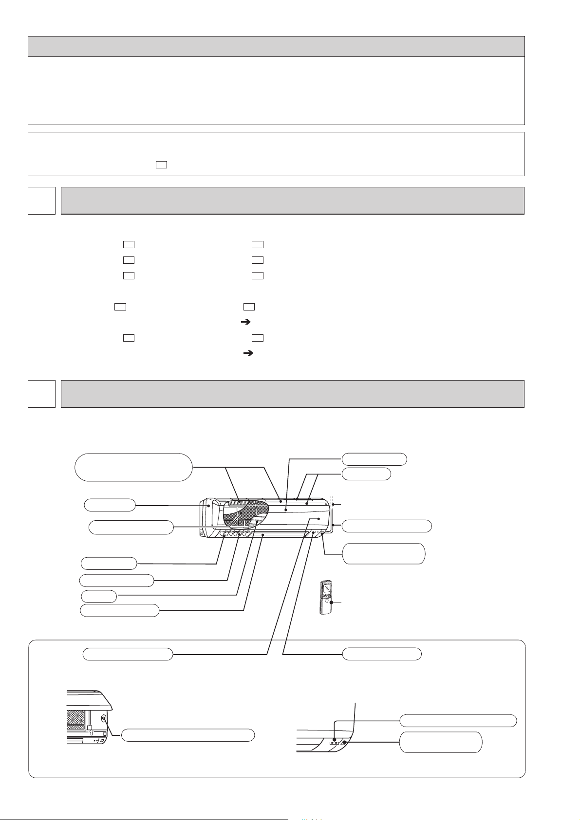
PART NAMES AND FUNCTIONS
MSC-GE20VB MSC-GE25VB MSC-GE35VB
Air cleaning filter(option)
(White bellows type)
Front panel
Air inlet
Panel
Catechin air filter
Air outlet
Vertical vanes
Fan
Horizontal vane
Operation section
(When the front panel is opened)
Emergency operation switch
to Breaker
Power supply cord
Remote control
receiving section
Remote controller
Display section
Operation indicator lamp
Remote control
receiving section
2

MS-GE50VB MSH-GE50VB
OBH529A
Air cleaning filter (option)
(White bellows type)
Panel
Catechin air filter
Vertical vanes
Horizontal vane
Operation section
(When the grille is opened)
Emergency operation switch
Front panel
Air inlet
To breaker
Power supply cord
Remote control
receiving section
Remote controller
Display section
Operation indicator lamp
Remote control
receiving section
ACCESSORIES
Installation plate
Installation plate fixing screw 4 25 mm
Remote controller holder
Fixing screw for 3.5 1.6 mm (Black)
Battery (AAA) for remote controller
Wireless remote controller
Felt tape (Used for left or left-rear piping)
MSC-GE20VB
MSC-GE25VB
MSC-GE35VB
1
5
1
2
2
1
1
MS-GE50VB
MSH-GE50VB
1
7
1
2
2
1
1
3

3
OBH529A
SPECIFICATION
Indoor model
Function
Power supply
Breaker capacity
Running current
Power input
Electrical
data
Power factor
Model
Fan motor current
Fan
motor
Dimensions W
Weight
Air direction
Air flow (High/Med./Low)
Sound level (High/Med./Low)
Fan speed (High/Med./Low)
Special
remarks
Fan speed regulator
Remote controller model
Indoor model
Function
Power supply
Breaker capacity
Running current
Power input
Power factor
Electrical data
Model
Fan motor current
Fan
motor
Dimensions W H D
Weight
Air direction
Air flow
Sound level
Special
remarks
Fan speed
Fan speed regulator
Remote controller model
NOTE: Test conditions are based on ISO 5151.
Cooling: Indoor Dry-bulb temperature 27°C Wet-bulb temperature 19 °C
Outdoor Dry-bulb temperature 35°C Wet-bulb temperature 24 °C
Heating: Indoor Dry-bulb temperature 20°C Wet-bulb temperature - °C
Outdoor Dry-bulb temperature 7°C Wet-bulb temperature 6°C
Indoor-Outdoor piping length: 5 m
H D
(High/Med./Low)
(High/Med./Low)
(High/Med./Low)
A
A
W
%
A
mm
kg
3
/h
m
dB
rpm
900/750/600
A
A
W
%
A
mm
kg
/h
dB
rpm
MSC-GE20VB
Cooling
Single phase
230 V, 50 Hz
RC4V19-JA
815
474/372/276
36/31/25
KM04F
MS-GE50VB
Cooling
Single phase
230 V, 50 Hz
RC4V32-BA
1,100 325 258
768/642/516
42/38/34
1,070/920/780
KM04B
Heating
10
0.17
35
90
0.17
278 244
9
5
510/420/342
36/31/25
950/820/700
3
0.3
60
87
0.3
16
5
3
MSC-GE25VB
Cooling
Single phase
230 V, 50 Hz
RC4V19-JA
815
474/384/306
36/31/25
900/770/650
MSC-GE35VB
Heating
10
0.17
35
90
0.17
278 244
9
5
588/456/342
39/32/25
1,050/870/700
3
KM04F
MSH-GE50VB
Cooling Heating
Single phase
230 V, 50 Hz
RC4V32-BA
1,100 325 258
768/642/516
42/38/34
1,070/920/780
582/444/324
930/760/600
1010
0.3
60
87
0.3
16
5
3
KM04A
Cooling
Single phase
230 V, 50 Hz
RC4V19-HA
815
40/33/26
10
0.19
40
92
0.19
278 244
10
5
606/498/396
960/830/700
3
KM04F
Heating
39/33/26
4
4
OBH529A
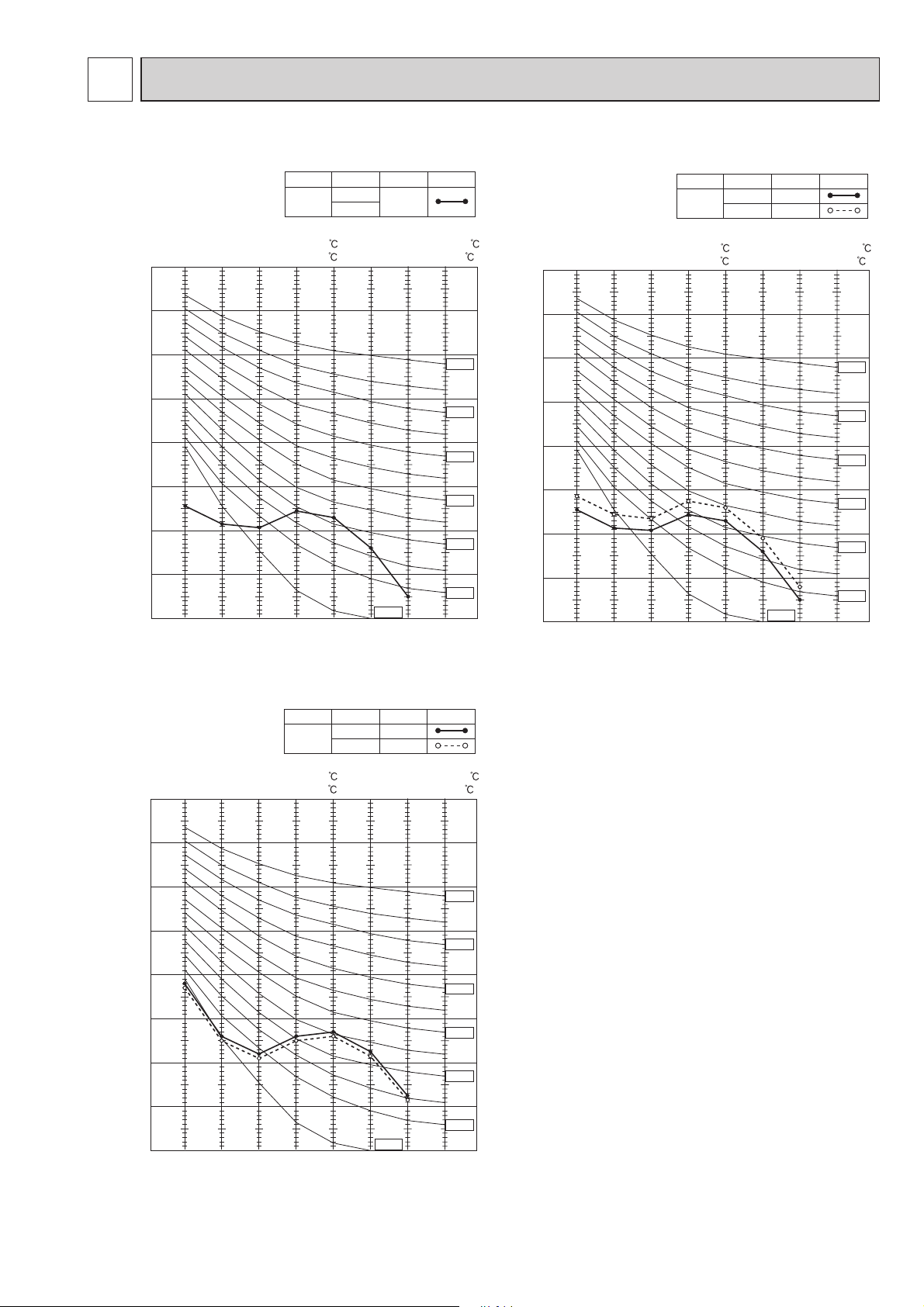
MSC-GE20VB
NOISE CRITERIA CURVES
SPL(dB
36
High
FUNCTIONFAN SPEED
COOLING
HEATING
Test conditions,
Cooling : Dry-bulb temperature 27 Wet-bulb temperature19
Heating : Dry-bulb temperature 20 Wet-bulb temperature -
90
(A))LINE
SPL(dB
MSC-GE25VB
High
FUNCTIONFAN SPEED
COOLING
HEATING 39
(A))LINE
36
Test conditions,
Cooling : Dry-bulb temperature 27 Wet-bulb temperature 19
Heating : Dry-bulb temperature 20 Wet-bulb temperature -
90
80
70
60
50
40
30
OCTAVE BAND SOUND PRESSURE LEVEL, dB re 0.0002 MICRO BAR
20
FUNCTIONFAN SPEED
COOLING
HEATING
NC-10
SPL(dB
40
39
(A))LINE
10
63 125 250 500 1000 2000 4000 8000
MSC-GE35VB
BAND CENTER FREQUENCIES, Hz
High
Test conditions.
Cooling : Dry-bulb temperature 27 Wet-bulb temperature 19
Heating : Dry-bulb temperature 20 Wet-bulb temperature -
90
NC-70
NC-60
NC-50
NC-40
NC-30
NC-20
80
70
60
50
40
30
OCTAVE BAND SOUND PRESSURE LEVEL, dB re 0.0002 MICRO BAR
20
10
63 125 250 500 1000 2000 4000 8000
BAND CENTER FREQUENCIES, Hz
NC-70
NC-60
NC-50
NC-40
NC-30
NC-20
NC-10
80
70
60
50
40
30
OCTAVE BAND SOUND PRESSURE LEVEL, dB re 0.0002 MICRO BAR
20
10
63 125 250 500 1000 2000 4000 8000
BAND CENTER FREQUENCIES, Hz
NC-70
NC-60
NC-50
NC-40
NC-30
NC-20
NC-10
5
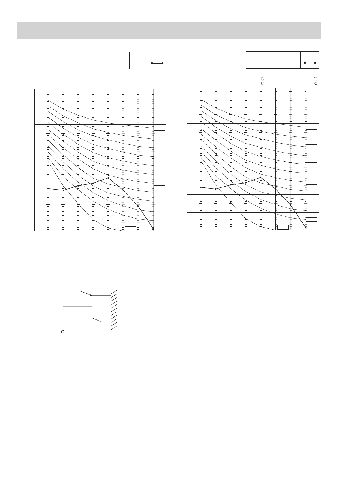
MS-GE50VB
OBH529A
High
FUNCTIONFAN SPEED
COOLING
(A))LINE
SPL(dB
42
Test conditions,
Cooling : Dry-bulb temperature 27°C Wet-bulb temperature 19°C
90
SPL(dB
MSH-GE50VB
High
FUNCTIONFAN SPEED
COOLING
HEATING
(A))LINE
42
Test conditions,
Cooling : Dry-bulb temperature 27 Wet-bulb temperature 19
Heating : Dry-bulb temperature 20 Wet-bulb temperature -
80
70
60
50
40
30
20
OCTAVE BAND SOUND PRESSURE LEVEL, dB re 0.0002 MICRO BAR
10
63 125 250 500 1000 2000 4000 8000
NC-10
BAND CENTER FREQUENCIES, Hz
NC-70
NC-60
NC-50
NC-40
NC-30
NC-20
80
70
60
50
40
30
20
OCTAVE BAND SOUND PRESSURE LEVEL, dB re 0.0002 MICRO BAR
10
63 125 250 500 1000 2000 4000 8000
NC-10
BAND CENTER FREQUENCIES, Hz
NC-70
NC-60
NC-50
NC-40
NC-30
NC-20
INDOOR UNIT
1m
0.8m
MICROPHONE
WALL
6
5
OBH529A
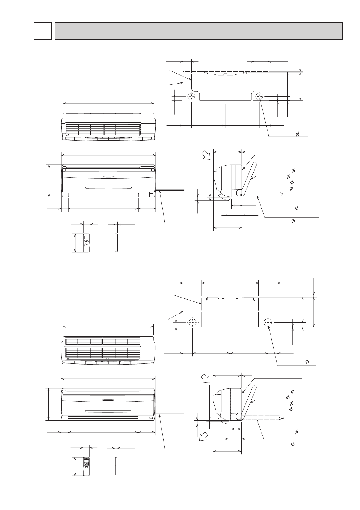
OUTLINES AND DIMENSIONS
MSC-GE20VB
MSC-GE25VB
278
60
58
162
606
783
815
Installation plate
Indoor unit
149
19
Power supply cord
Lead to right 1.0m
Lead to left 0.3m
81.5
41
81.5
Air in
30
Air out
242 5
7 or more
244
326326
Installation plate
{
90
110
133.5
4.5
271
231.5
42
2.5
81.5
Wall hole 65
Liquid line 6.35-0.5m
Gas line 9.52-0.43m
Insulation 37 O.D
21 I.D
Drain hose 16
(Connected part O,D)
Insulation 28
Unit: mm
Wireless remote controller
MSC-GE35VB
278
60
58
162
606
783
815
Installation plate
Indoor unit
149
19
Power supply cord
Lead to right 1.0m
Lead to left 0.3m
41
Air in
30
Air out
242
7 or more
244
161.5161.5
326326
5
Installation plate
{
90
110
81.581.5
Wall hole 65
Liquid line 6.35-0.5m
Gas line 9.52-0.43m
Insulation 37 O.D
21 I.D
Drain hose 16
(Connected part O,D)
Insulation 28
2.5
218.5
42
Unit: mm
17.5
258
Wireless remote controller
7
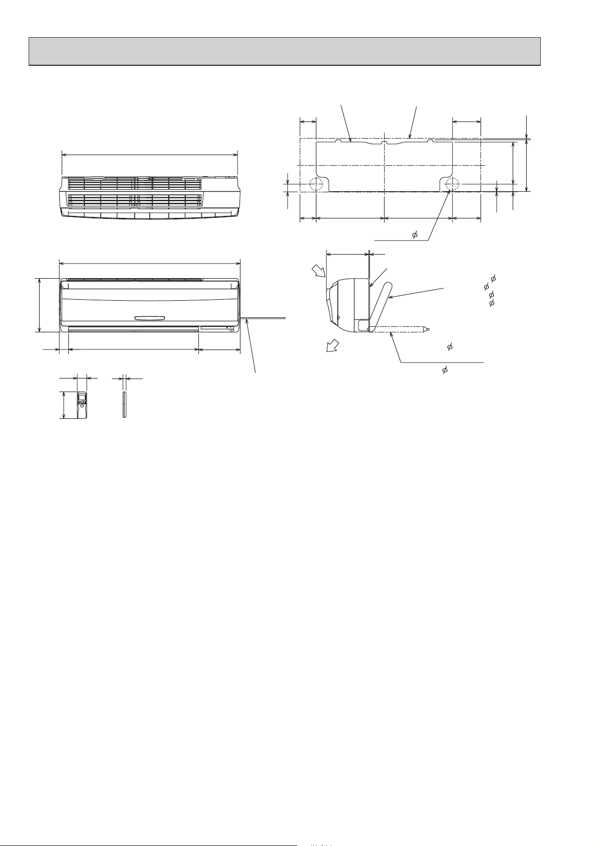
MS-GE50VB
OBH529A
MSH-GE50VB
1068
Installation plate
98
Indoor unit
173
Unit: mm
7.5
255.547
315
325
56
58
162
Wireless remote controller
110 0
791
19
253
Power supply cord
Lead to right 2.0 m
Lead to left 1.0 m
47
98 173414.5 414.5
Wall hole 75
258
Air in
Air out
5
Installation plate
Liquid line 6.35- 0.5 m
Gas line
{
Insulation
Drain hose 16
(Connected part O.D)
Insulation 28
2.5
12-0.43 m
50 O.D
32 I.D
8

6
OBH529A
MSC-GE20VB MSC-GE25VB MSC-GE35VB
WIRING DIAGRAM
MS-GE50VB
MSH-GE50VB
9
7
OBH529A
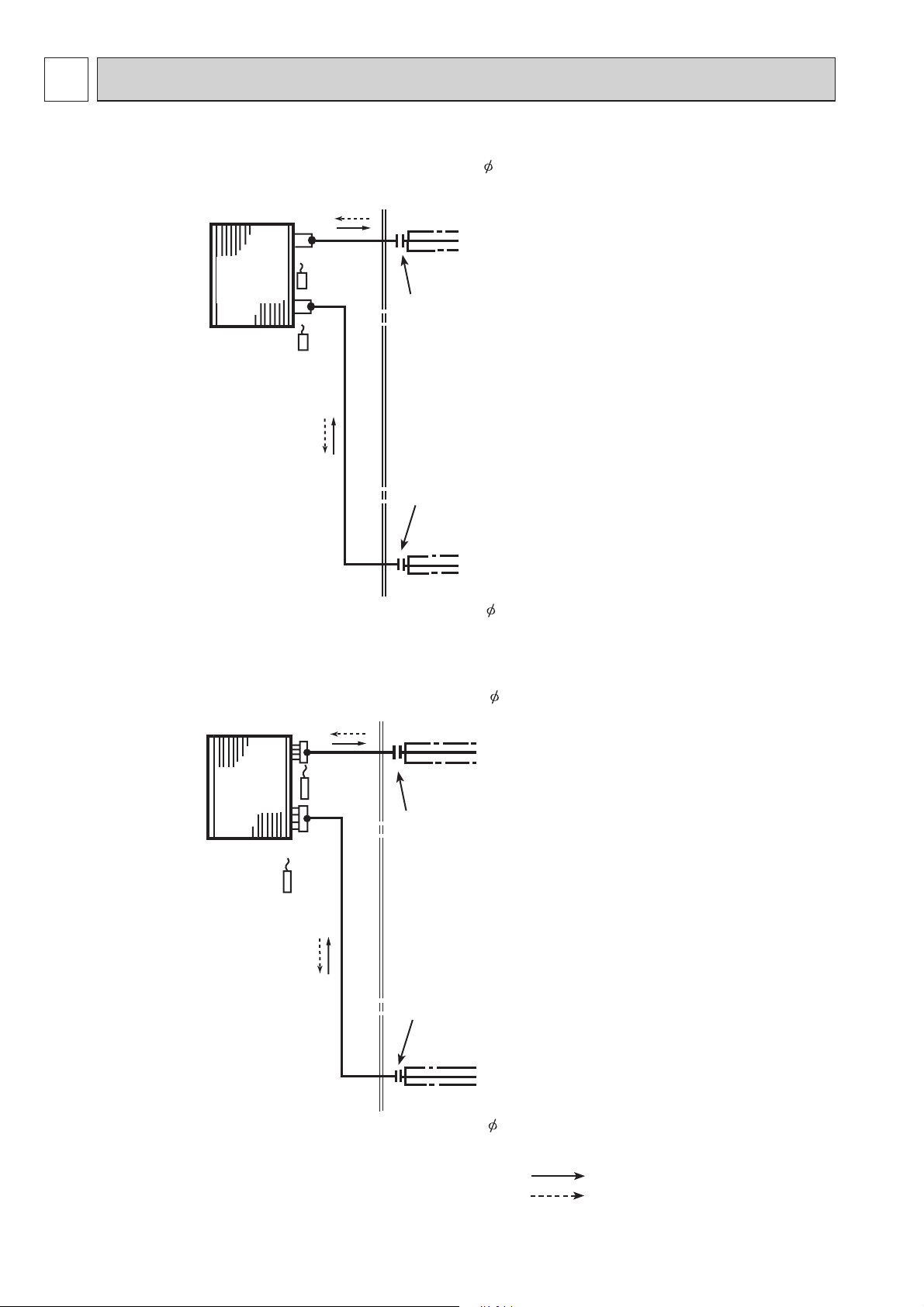
REFRIGERANT SYSTEM DIAGRAM
MSC-GE20VB MSC-GE25VB MSC-GE35VB
Refrigerant pipe 9.52
(with heat insulator)
Unit:mm
Indoor
heat
exchanger
Room temperature
thermistor
RT11
MS-GE50VB MSH-GE50VB
Indoor coil
thermistor
RT12
Flared connection
Flared connection
Refrigerant pipe 6.35
(with heat insulator)
Refrigerant pipe 12.7
(with heat insulator)
Indoor
heat
exchanger
Room temperature
thermistor
RT11
Indoor coil
thermistor
RT12
Distributor
Flared connection
Flared connection
Refrigerant pipe 6.35
(with heat insulator)
Refrigerant flow in cooling
Refrigerant flow in heating (MSC,MSH)
10
8
OBH529A
SERVICE FUNCTIONS
MSC-GE20VB MS-GE50VB
MSC-GE25VB MSH-GE50VB
MSC-GE35VB
8-1. TIMER SHORT MODE
For service, set time can be shortened by short circuit of JPG and JPS on the electronic control P.C. board. (Refer to 10-6.)
The time will be shortened as follows.
Set time: 1 minute 1-second
Set time: 3 minute 3-second (It takes 3 minutes for the compressor to start operation. However, the starting time is short-
ened by short circuit of JPG and JPS.)
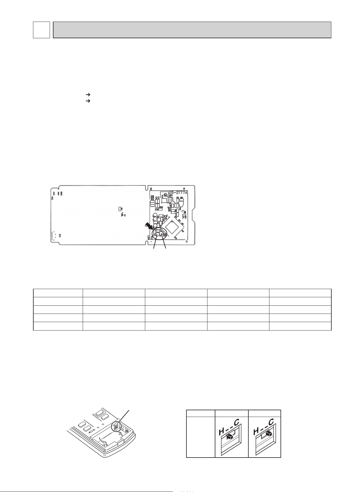
8-2. P.C. BOARD MODIFICATION FOR INDIVIDUAL OPERATION
A maximum of 4 indoor units with wireless remote controllers can be used in a room.
In this case, to operate each indoor unit individually by each remote controller, P.C. boards of remote controller must be
modified according to the number of the indoor unit.
How to modify the remote controller P.C. board
Remove batteries before modification.
The board has a print as shown below:
NOTE: For modification, take out the batteries and press the OPERATE/STOP (ON/OFF) button 2 or 3 times at first.
After modification, put back the batteries then press the RESET button.
J2
J1
The P.C. board has the print “J1” and “J2”. Solder “J1” and “J2” according to the number of indoor unit as shown in Table 1.
After modification, press the RESET button.
Table 1
1 unit operation
No. 1 unit
No. 2 unit
No. 3 unit
No. 4 unit
How to set the remote controller exclusively for particular indoor unit
After you turn the breaker ON, the first remote controller that sends the signal to the indoor unit will be regarded as the
remote controller for the indoor unit.
The indoor unit will only accept the signal from the remote controller that has been assigned to the indoor unit once they are
set. The setting will be cancelled if the breaker has turned off, or the power supply has shut down.
Please conduct the above setting once again after the power has restored.
No modification
–
–
–
2 units operation
Same as at left
Solder J1
–
–
3 units operation
Same as at left
Same as at left
Solder J2
–
4 units operation
Same as at left
Same as at left
Same as at left
Solder both J1 and J2
8-3. REMOTE CONTROLLER (How to set the type) MSC-GE
This remote controller setting needs to be switched according to the type of air conditioner (COOL & HEAT or COOL
ONLY).
If the setting is incorrect, the air conditioner does not operate normally. Therefore, check if the setting corresponds to the
type of-air conditioner. If not, correct the setting as shown below.
Slide switch
Type
COOL ONLYCOOL & HEAT
The position
of the slide
switch
11
 Loading...