

Mitsubishi Electric Ecodan PUHZ-W50VHA-BS, Ecodan PUHZ-W85VHA-BS, Ecodan PUHZ-HW140VHA-BS, Ecodan PUHZ-HW140YHA-BS Homeowner's Manual

1
Ecodan® Air Source Heat Pump
Home Owner Guide
PUHZ-W50VHA-BS
PUHZ-W85VHA-BS
PUHZ-HW140VHA-BS / YHA-BS

2
Contents
INTRODUCTION
• Heat Pump Overview 3
• Co-efficient of performance 3
• Varying Factors 3
• How a heat pump works 4
• Room thermostat 5
• Controller PAR-W21MAA 5
• Hot Water / Space Heating 5
• Selecting cylinder thermostat 5
• Weather Compensation 5
COMPONENT PARTS
• Key Parts 6
SPECIFICATION
• PUHZ-W50VHA-BS 7
• PUHZ-W85VHA-BS 8
• PUHZ-HW140VHA-BS / YHA-BS 9
CONTROLLER SET-UP
• Display and Operation 10
• Change Language 11
• Setting Day and Time 11
• Heating Set-up 12
• Recommended Settings 13
• Radiators 13
• Hot water Set-up 13
• Available Modes 14
• How to lock/unlock buttons 15
• Error codes indication 15
• Displays 16
OPERATING CONDITIONS
• Flow Rates 17
• Start Up 17
• Control Strategy 17
RUNNING COSTS
• Running Costs 18
ADDITIONAL INFORMATION
• Time Clock Set-Up/ Patterns 19
• Domestic Hot Water Immersion Heater 20
• Legionnaires Disease 20
• FAQ’s 20
TROUBLESHOOTING
• Troubleshooting 21
• Maintenance 21
Abbreviations / Glossary of terms
Ambient Temperature The outdoor temperature
Anti freeze mode Heating to prevent water pipe from freezing
ASHP Air source heat-pump boiler
COP Coefficient of performance, see page 3 for full explanation
∆T / Delta Change in temperature between two variables
Flow Rate The speed the water travels within the circuit that is heated by the Ecodan® unit
Flow Temperature The temperature of the water within the circuit that is heated by the Ecodan® unit
FTC Flow Temperature Controller, see page 6 for full explanation
Heating Eco mode Similar to ’heating mode’ with weather compensation
Heating Mode For heating space either through radiators or under floor heating
Hot water mode Heating of the tank to provide hotwater
Immersion Heater Booster heater to raise temperatures, see page 21 for use with Ecodan® unit
Refrigerant A compound used within a heat cycle that goes through a phase change during this cycle
changing from gas to liquid and back again
UFH Under Floor Heating
Weather compensation Flow temperatures change dependent on outdoor conditions, see page 5 for full explanation

3
Heat Pump Boiler Overview
A heat pump works in a similar way to that of a domestic fridge, although in reverse. Heat is moved from one source to another. The outdoor based Ecodan
exploits the physical properties of a refrigerant to heat water that flows into the
dwelling to the radiators/ under-floor heating and the hot water cylinder for hot
water usage. This is a very efficient way to heat water compared to conventional
gas, oil and solid fuel boilers.
Co-efficient of Performance
Sometimes referred to as COP, it is the amount of heat energy provided by the
heat pump, divided by the electrical energy consumed by the heat pump.
The efficiency of a heat pump boiler is high compared to a gas boiler. Typically for
every 1kW of input energy, 3kW of outputted heat energy can be achieved, that
creates a COP of 3.0. If heat energy increases for the same input the COP would
rise.
Compared to a gas fired conventional boiler, 1kW of input energy provides less
than 1kW of output energy or heat. A heat pump boiler utilises heat energy from
the outside air even at low temperatures to provide either central heating or hot
water for the house.
The COP for an ASHP will vary as it is dependent on the outside temperatures
and the desired temperature of hot water/ space heating. The smaller the difference between these figures the more efficient the Ecodan® will become. When it
is cold outside power input increases as the Ecodan® works harder to extract
heat from the air, thus COP drops in cold conditions.
Varying Factors
The table below shows how performance will vary. The Inlet/ Outlet temperature
represents the water temperature
progressing through the Ecodan®
unit and heating up.
Figures for 8.5kW heat pump
* Ambient Temperature –10°C
INTRODUCTION
°C ambient
Water temp °C
Inlet / Outlet
30 / 35 40 / 45 50 / 55
-15 1.77 1.41 1.37*
-7 2.41 1.89 1.46
2 2.97 2.27 1.81
7 3.96 3.05 2.28
20 5.39 3.90 2.87
COP at varying factors
4
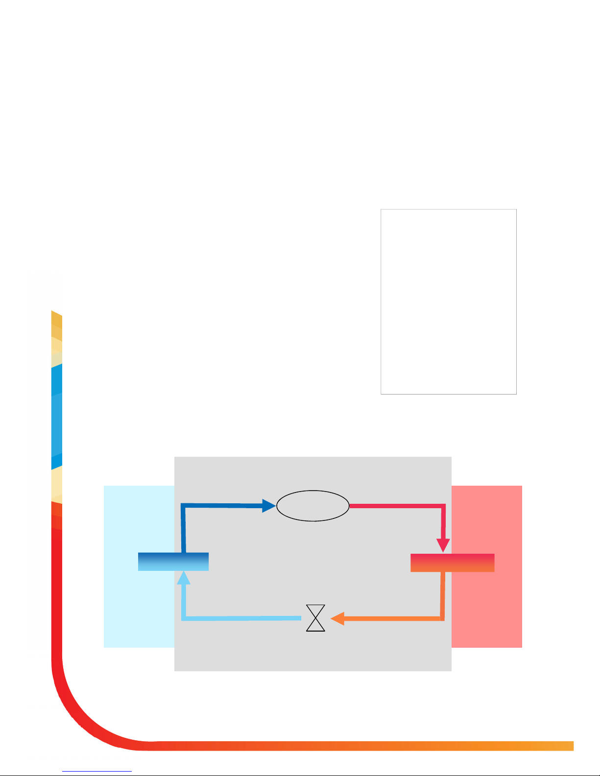
How a heat pump works
The heat pump essentially works the same way as your refrigerator but in reverse.
The Ecodan® is hermetically sealed (no refrigeration piping involved) with R410A
refrigerant, the cycle it completes to produce heat is known as the vapourcompression refrigeration cycle:
The first phase begins with the refrigerant being cold and low pressure.
The refrigerant within the circuit is compressed as it passes through the
compressor. It becomes a hot highly pressurized gas. The temperature also
rises typically to 60°C
The refrigerant is then condensed as it passes across a plate heat ex-
changer. Having a cooler side to the heat exchanger it decreases the temperature, so it changes the property of the refrigerant from a gas to a liquid.
Now a cold liquid it still has a high pressure. For expansion to occur it passes
through an expansion valve. The pressure drops but it is still a cold liquid.
The final stage of the cycle is when the refrigerant passes into the evaporator
and evaporates. It is at this point when some of the free heat energy in the
outside air is absorbed by the refrigerant.
It is only the refrigerant that is being passed through this cycle; the water is heated
up by the plate heat exchanger. The cooler water extracts energy from the hotter
refrigeration cycle, the water heats up as it passes across the exchanger. This water flows towards the heating system and hot water storage tank.
Boiling points:
The refrigerant used within the cycle
has a different boiling point to water,
which boils (turns from liquid to gas)
at 100°C. This is only true at atmospheric pressure. When the pressure
increases so does the boiling temperature; decrease the pressure and boiling
temperature drops. Liquid turns to gas
at a lower temperature. The boiling
point changes when the pressure
changes. Refrigerants have different
properties to water and have much
lower boiling temperatures. During the
fourth stage of the cycle the outside
ambient temperature is much hotter
than the temperature of the refrigerant and will heat it.
Step 1
Step 2 Step 3 Step 4
INTRODUCTION
compressor
Heat Exchanger
Evaporator
Expansion
1 compressed
2 condensed
3 expansion
4 evaporates
Outside Air
Sealed Ecodan® Unit
Hot water for heat-
ing and hot water

5
Room Thermostat
The aim of the thermostat is to control the room temperature, although one model used will vary from
one home to another its function will not. This is the homeowner’s connection to the heat pump boiler.
The room thermostat and the time clock (both supplied by 3rd party manufacturers.) are the 2 main controls for the home owner to use.
Controller PAR-W21MAA
This controller is supplied with the Ecodan® heat pump. Its primary function is as a commissioning tool to
set the target flow temperature. It has a display to show the actual flow temperature and the target temperature. The set-up, displays and modes available are explained later in the manual. Once installed there
are factory settings that will allow the heat pump boiler to start operating immediately, optimising these
temperatures to suit your home will improve running conditions and lower your energy consumption.
These temperatures should be selected during the commissioning stage.
Hot water / space heating
Space heating and hot water heat up cannot be performed at the same time. Hot water will always take
priority over space heating should there be a demand for both; once the tank is heated and up to temperature the unit will change over to the heating of the property. This setting cannot be changed.
Due to lower flow temperature provided by a heat pump boiler additional care must be taken when sizing
the radiators. Ensure that the total heating demand of the property is met by the correct size of heat
pump.
Selecting cylinder thermostats
Care should be taken when selecting a cylinder thermostat. If the thermostat is set higher than the achievable storage temperature of 55°C then space heating will be held off due to hot water priority. It is recommended that a thermostat on which the maximum temperature can be locked is used. This will prevent
the stat asking for a temperature that cannot be achieved thus preventing space heating from occurring.
(See page 18 for typical heat up times for the hot water tank).
Weather Compensation
The Ecodan® system has a weather compensation mode. This feature is called Eco-heating. This mode
offers varying flow temperatures to the radiators depending on the outside temperature. These temperatures are selected and set by the installer when commissioning the Ecodan® system for further details see
the controller set-up. It is recommended that Eco-heating mode is used for central heating.
INTRODUCTION
6
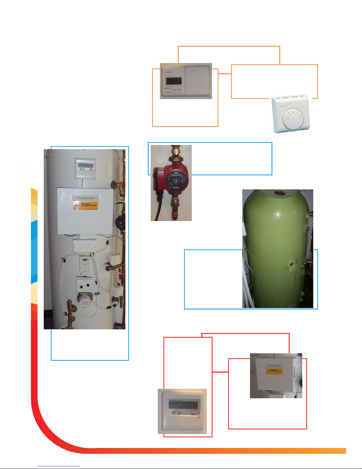
Hot water tank:
Within this tank the
water is heated via a
coil positioned inside,
the heated water leaves
the top of the tank for
showers, baths and
taps.
Pump:
This moves the flow of heated
water from the Ecodan® to the
heating system and hot water tank.
Controls, pumps and other components supplied and packaged
together
Component Parts
The installed Ecodan® will include
several key parts. Some of their functions will require human input to control the effect of the unit,
COMPONENT PARTS
Main Home Owner Controls
Room Thermostat:
Used by homeowner to set the required temperature of the household
Two Channel Timer Clock:
Used by homeowner to set
on/off running periods
Mitsubishi Supplied Parts
PAR-W21MAA:
Controller used
to activate settings on Ecodan®.
These settings are
explained in later
pages.
Flow Temperature Controller::
Within this box is the brains behind the system that allows the
Ecodan® to speak to the boiler
7
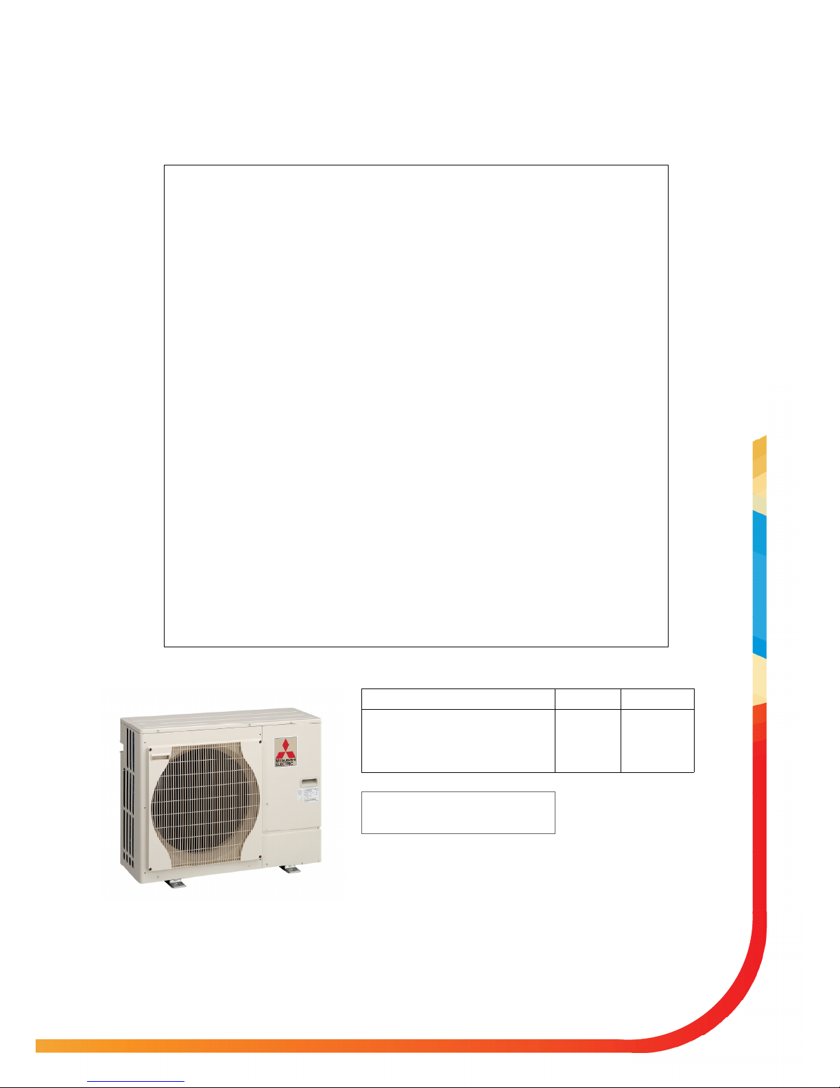
Specifications PUHZ-W50VHA-BS
Dimensions (mm) Width 950
Depth 330+30*
Height 740
Weight (kg) 64
Airflow (m3/min) 50
Nominal sound level (dBA) 45 ◊
Low noise mode (dBA) @ 7°C 40
Guaranteed operating range (Outdoor) - 15 ~ +35°C
Electrical Supply 220-240v, 50Hz
Phase Single
Running current (A) [Max] 5.4 [13]
Fuse Rating (A) 16
Heating A2/W35 Capacity (kW) 5.0
COP 3.13
Power Input (kW) 1.6
Nominal Flow Rate (L/min) 14.3
Heating A7/W35 Capacity (kW) 5.0
COP 4.1
Power Input (kW) 1.22
Nominal Flow Rate (L/min) 14.3
Primary Flow Rate Maximum (L/min) 25.8
Minimum (L/min) 10
PUHZ-W50VHA-BS
SPECIFICATION
Nominal Conditions A2 / W35 A7 / W35
Outside air temperature (humid) 1°C 6°C
Water temperature (inlet/outlet) 30 / 35°C 30 / 35°C
* Grille
◊ At distance of 1m from the outdoor unit
Outside air temperature (dry) 2°C 7°C
 Loading...