

Page 1

Air Conditioning Control System
Centralized Controller
EB-50GU-A/EB-50GU-J
Before using the controller, please read this Instruction Book carefully to ensure proper operation.
Retain this manual for future reference.
Instruction Book
–Web Browser for System Maintenance Engineer–
1. Introduction ...........................................................................2
1-1. Terms Used in This Manual .........................................................2
1-2. PC Requirements .........................................................................2
2. Setting the Operating Environment ......................................3
2-1. Setting the IP Address of the PC ...... ...........................................3
2-2. Setting the Web Browser .............................................................5
3. Logging in to the Web Browser for System Maintenance
Engineer ...............................................................................8
4. Monitor/Operation ...............................................................11
4-1. Condition List .............................................................................11
4-2. Measurement List ......................................................................19
4-3. Malfunction List ..........................................................................20
4-4. Filter Sign List ............................................................................22
4-5. AHC List .....................................................................................23
5. Energy Management ..........................................................25
5-1. Energy Use Status .....................................................................25
5-2. Ranking ......................................................................................31
5-3. Target Value Setting ...................................................................34
5-4. Peakcut Control Status ..............................................................36
6. Schedule Settings...............................................................38
6-1. Weekly Schedule .......................................................................40
6-2. Annual Schedule ........................................................................45
6-3. Today's Schedule .......................................................................48
7. Malfunction Log ..................................................................50
7-1. Unit Error/Communication Error .................................................50
8. System Settings..................................................................51
8-1. Date/Time Settings ....................................................................51
8-2. User Registration .......................................................................52
9. Maintenance .......................................................................53
9-1. Send Mail Log ............................................................................53
9-2. Gas Amount Check ....................................................................54
9-3. Outdoor unit status .....................................................................55
9-4. Free Contact List ........................................................................56
9-5. CSV output .................................................................................57
10. License registration for optional functions ........................68
Contents
Page 2

2
1. Introduction
Mitsubishi Electric Corporation’s Centralized Controller EB-50GU-A/EB-50GU-J features functions to allow users
to monitor and operate the air conditioning units from a PC over the LAN.
This Instruction Book explains how to monitor and operate the units connected to the EB-50GU-A/EB-50GU-J
using a Web browser.
For initial settings and function settings, refer to the Instruction Book (Web Browser for Initial Settings).
1-1. Terms Used in This Manual
- "Centralized Controller EB-50GU-A/EB-50GU-J" is referred to as "EB-50."
- "Booster unit" and "Water HEX unit" are referred to as "Air To Water (PWFY) unit."
- "Advanced HVAC CONTROLLER" is referred to as "AHC."
- Screen images used in this manual are from Windows 7® and Internet Explorer 9.0.
Note: Windows is a registered trademark or trademark of Microsoft Corporation in the United States and other countries.
1-2. PC Requirements
Table1-1 PC Requirements
Item Requirement
CPU 1 GHz or faster
Memory 512 MB or more
Screen resolution 1024 x 768 or higher recommended
Browser
Microsoft
®
Internet Explorer 8.0
Microsoft
®
Internet Explorer 9.0
* Java execution environment is required.
(Oracle
®
Java Plug-in Ver. 1.7.0_11)
* Install Oracle
®
Java Plug-in that is appropriate for your operating system. When
using a 64-bit Internet Explorer, install a 64-bit Java Plug-in.
* The version of the Oracle
®
Java Plug-in can be verified by clicking [Java] in the
Control Panel.
On-board LAN port or LAN card 100 BASE-TX
Pointing device e.g., mouse
Note: Microsoft is a registered trademark or trademark of Microsoft Corporation in the United States and/or other countries.
Oracle and Java are trademarks or registered trademarks of Oracle Inc. in the United States and/or other countries.
Page 3
3
2. Setting the Operating Environment
This chapter explains how to make PC settings and Web browser settings to monitor and operate the air
conditioning units.
2-1. Setting the IP Address of the PC
Follow the instructions below to set the PC's IP address for the Web browser to recognize the EB-50 unit.
The PC's IP address must have the same network address as the EB-50's IP address.
(i.e., EB-50's IP address: [192.168.1.1], PC's IP address: [192.168.1.101])
When connecting an EB-50 to an existing LAN, consult the system administrator to decide the IP address of the
PC.
Note: When using an EB-50-dedicated LAN, it is recommended that the main EB-50 unit be assigned an IP address
between the range [192.168.1.1] and [192.168.1.40] and that the PC connected to the EB-50 be assigned an IP
address between the range [192.168.1.101] and [192.168.1.150].
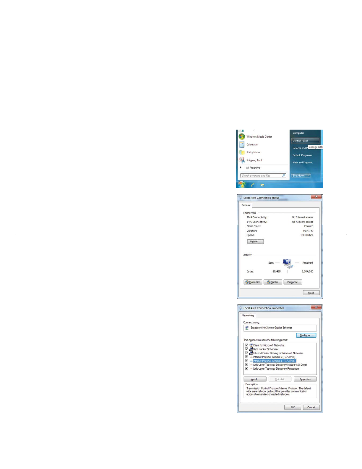
(1) Click [Control Panel] in the Start menu.
(2) Click [Network and Sharing Center]>[Local Area Setting].
In the [Local Area Connection Status] window, click [Properties].
(3) Click [Internet Protocol Version 4 (TCP/IPv4)] to select it, and click
[Properties].
Page 4

4
(4) In the [Internet Protocol Version 4 (TCP/IPv4) Properties] window,
check the radio button next to [Use the following IP address].
Enter the PC’s IP address (e.g., [192.168.1.101]) in the [IP address]
field, and enter the subnet mask [255.255.255.0] (unless otherwise
specified) in the [Subnet mask] field.
In the [Default gateway] field, enter the gateway address as
necessary.
Note: Consult the system administrator to decide the IP, subnet
mask, and gateway addresses.
(5) Keep clicking [OK] or [Close] to close all windows.
Page 5
5
2-2. Setting the Web Browser
Web browser setting varies with the Internet connection type. See the sections below for how to make Web
browser settings for different types of Internet connection.
To prevent unauthorized access, always use a security device such as a VPN router when
connecting the EB-50 to the Internet.
2-2-1. No Internet connection
To monitor and operate the air conditioning units from a PC with no Internet connection, follow the instructions
below to set the environment for the Web browser.
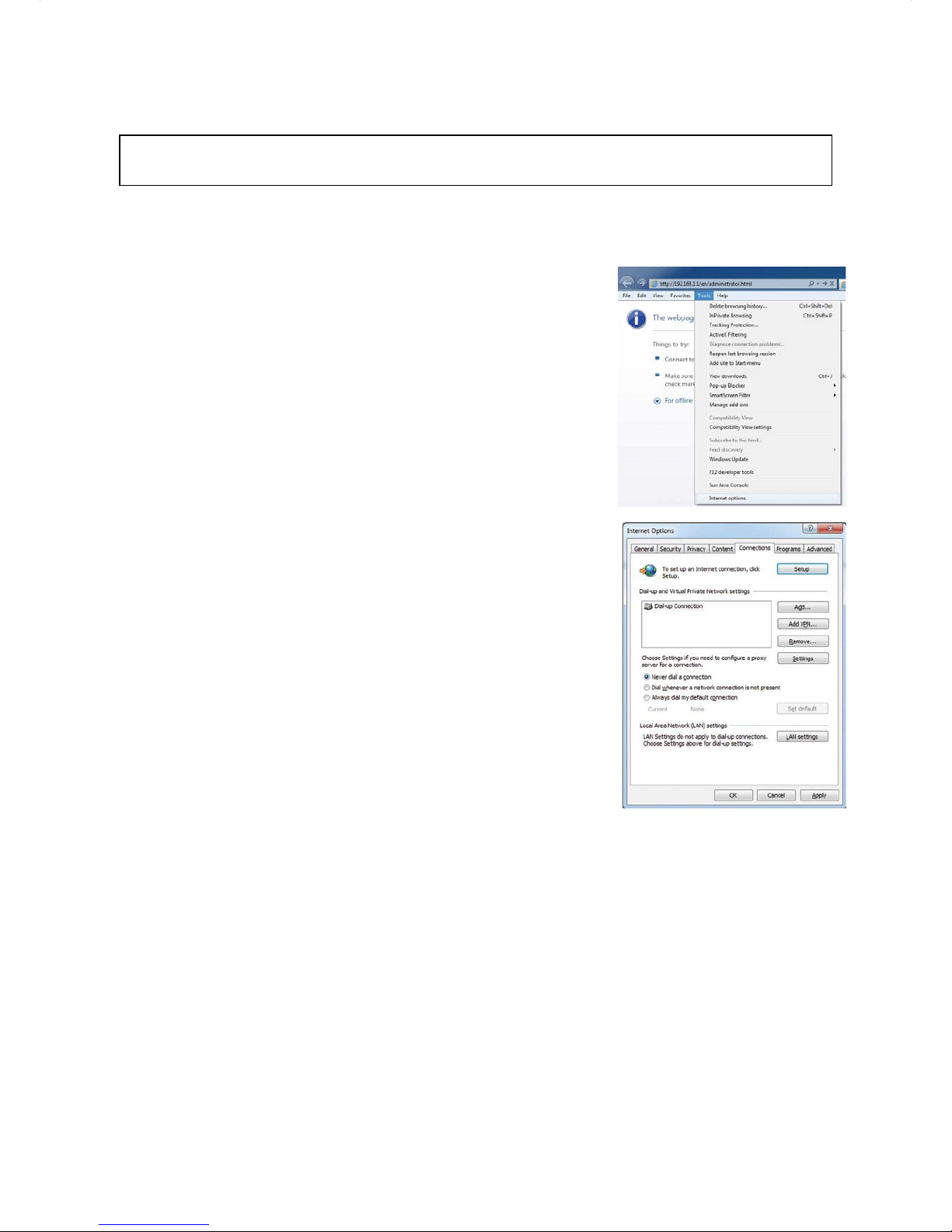
(1) Click [Tools] in the menu bar, then click [Internet options].
(2) In the [Internet Options] window, click the [Connections] tab.
(3) Check the radio button next to [Never dial a connection] in the middle
of the window, and click [OK] to close the window.
Page 6
6
2-2-2. Dial-up Internet connection
To monitor and operate the air conditioning units from a PC that connects to the Internet through a dial-up
connection, follow the instructions below to set the environment for the Web browser.
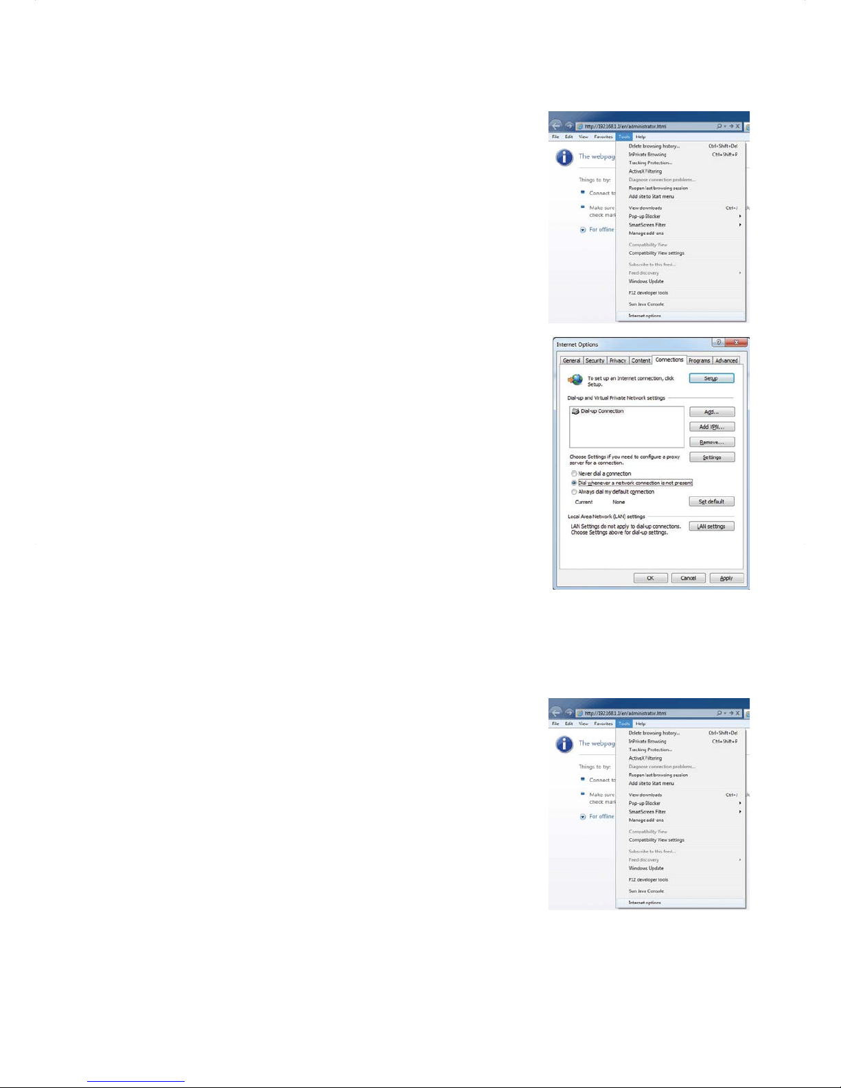
(1) Click [Tools] in the menu bar, then click [Internet options].
(2) In the [Internet Options] window, click the [Connections] tab.
(3) Check the radio button next to [Dial whenever a network connection
is not present] in the middle of the window, and click [OK] to close the
window.
By making these settings, a message will appear asking whether
or not to use a dial-up connection when an Internet connection is
necessary. Follow the message to connect to the Internet.
2-2-3. Connecting to the Internet via proxy server using an existing LAN
To monitor and operate the air conditioning units from a PC that connects to the Internet through a proxy server
by connecting to an existing LAN, such as a LAN within your company, follow the instructions below to set the
environment for the Web browser.
(1) Click [Tools] in the menu bar, then click [Internet options].
Page 7
7
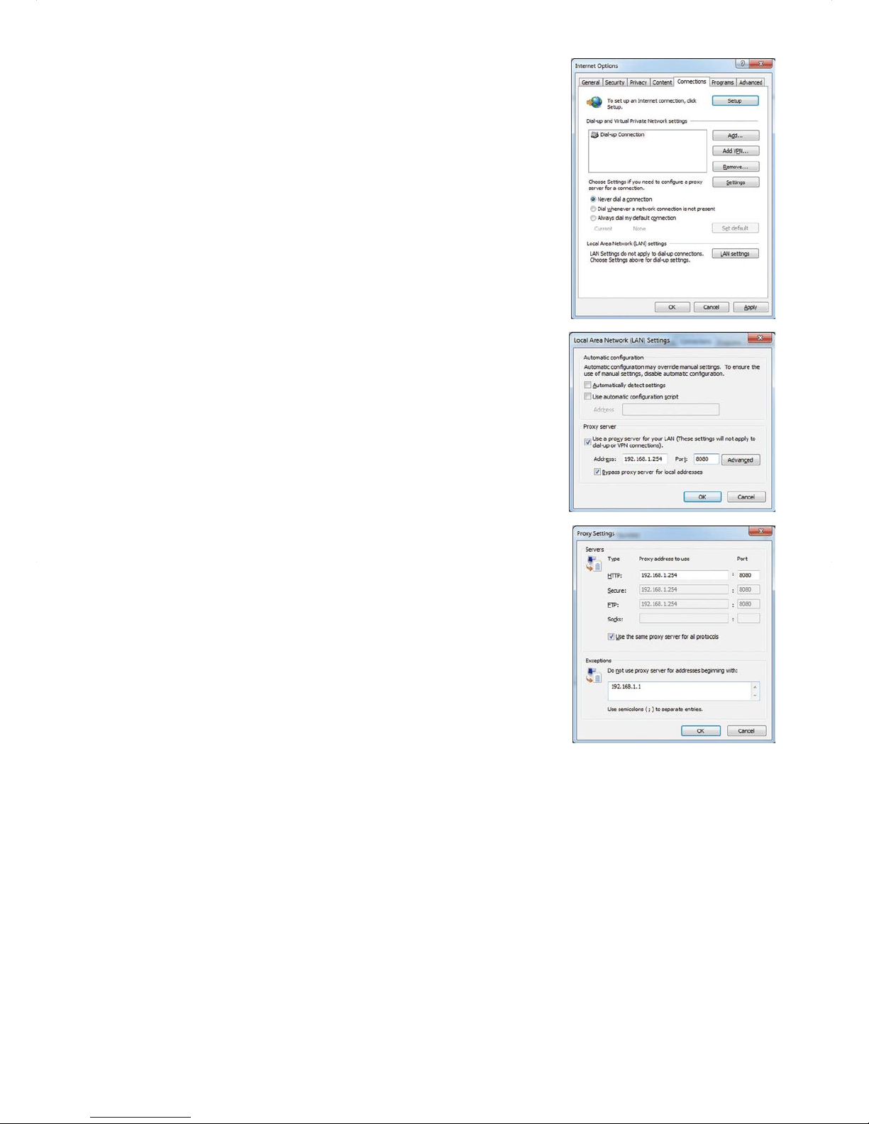
(2) In the [Internet Options] window, click the [Connections] tab.
(3) Check the radio button next to [Never dial a connection] in the middle
of the window.
(4) Click [LAN settings] under [Local Area Network (LAN) settings].
(5) In the [Local Area Network (LAN) Settings] window, check [Bypass
proxy server for local addresses], and click [Advanced].
(6) In the [Proxy Settings] window, enter the EB-50’s IP address (e.g.,
192.168.1.1) in the [Exceptions] field. Then, keep clicking [OK] or
[Close] to close all windows.
If connecting multiple EB-50 units, enter the addresses of all EB-50
units (e.g., [192.168.1.1; 192.168.1.2]). It is also possible to use an
asterisk as a wildcard (e.g., [192.168.1.*]).
Page 8
8
3. Logging in to the Web Browser for System
Maintenance Engineer
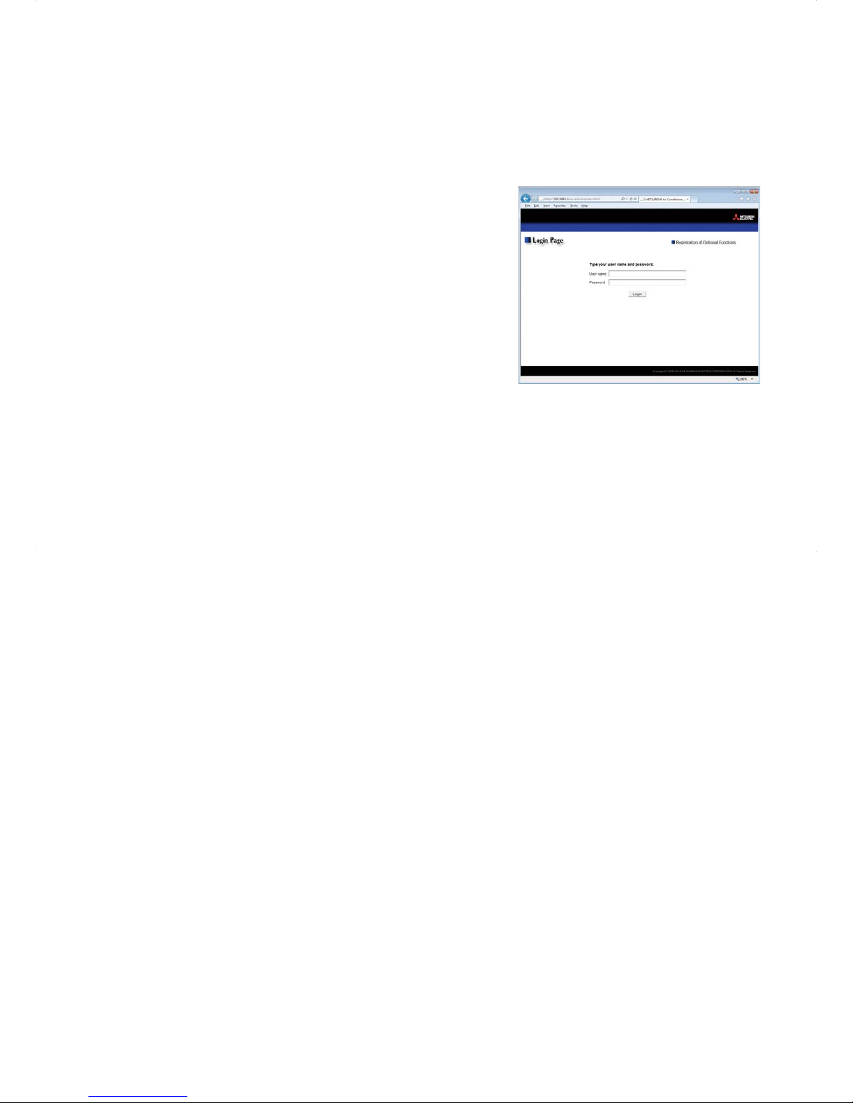
(1) Enter the web page address in the address field of the Web browser as follows:
http ://[IP address of the EB-50]/administrator.html
Press the [Enter] key. A login screen will appear.
Note: If the IP address of the EB-50 is [192.168.1.1], the web page
address is [http ://192.168.1.1/administrator.html].
Note: Default IP address of EB-50 is [192.168.1.1].
Note: If the login screen does not appear then take the steps below
to delete the temporary files.
<Internet Explorer>
1. Click [Tools] in the menu bar, then click [Internet options].
2. On the [General] tab, click [Delete] in the middle of the
window.
3. In the [Delete Browsing History] window, click [Delete].
<Java>
1. Click [Control Panel] from the Start menu.
2. Click the [Java] icon to launch the Java Control Panel.
3. On the [General] tab, click [Settings] in the [Temporary
Internet Files] section.
4. Click [Delete Files].
5. In the [Delete Files and Applications] window, click [OK].
Note: The web page will be displayed in the same language as the operating system on the PC.
The web page can be displayed in other languages by entering the web page address as follows:
Chinese
http ://[IP address of the EB-50]/zh/administrator.html
English
http ://[IP address of the EB-50]/en/administrator.html
French
German
Italian
Japanese
http ://[IP address of the EB-50]/fr/administrator.html
http
://[IP address of the EB-50]/de/administrator.html
http ://[IP address of the EB-50]/it/administrator.html
http ://[IP address of the EB-50]/ja/administrator.html
Portuguese http ://[IP address of the EB-50]/pt/administrator.html
Russian
http ://[IP address of the EB-50]/ru/administrator.html
Spanish
http ://[IP address of the EB-50]/es/administrator.html
Note: You can add the web page address to your Favorites for easy access in the future.
Page 9

9
(2) Enter the user name and the password in the login screen, and click [Login]. A screen for monitoring the
operation conditions will appear.
The table below shows the web page addresses for building managers and general users, their respective
default user names and passwords, and their accessible functions.
User Web page address
Default
user name
Default
password
Available functions
Building
manager
http ://[IP address
of the EB-50]/
administrator.html
administrator admin
Monitor/
Operation
Condition List
Measurement List
Malfunction List
Filter Sign List
AHC List
Energy
Management
Energy Use Status
Ranking
Target Value Setting
Peakcut Control Status
Schedule
Settings
Today's Schedule
Weekly Schedule 1
Weekly Schedule 2
Weekly Schedule 3
Weekly Schedule 4
Weekly Schedule 5
Annual Schedule
Malfunction
Log
Unit Error
Communication Error
System
Settings
Date/Time Settings
User Registration
Maintenance
Send Mail Log
Gas Amount Check
Outdoor unit status
Free Contact List
CSV output
General
user
http ://[IP address of
the EB-50]/index.html
guest guest
Monitor/
Operation
Condition List
Note: The license "Personal Web" is required to register up to 50 general users and to specify the accessible unit groups for each
general user. Refer to section 8-2 "User Registration" for details.
Note: It is recommended to change the default user name and password so that the users other than the building managers and
general users will not be able to change the settings.
Page 10
10
Encrypting the communication data and logging in to the Web browser
(HTTPS connection)
EB-50 can encrypt communication data using HTTPS (SSL).
When connecting the EB-50 to the LAN that is accessible to the general public, it is recommended that the
following settings be made so that the units are monitored and controlled on the encrypted web page.
Note: Depending on the operating system or the Java version, HTTPS encrypted communication may not be enabled
properly. If this happens, use an HTTP connection as explained in the previous page.
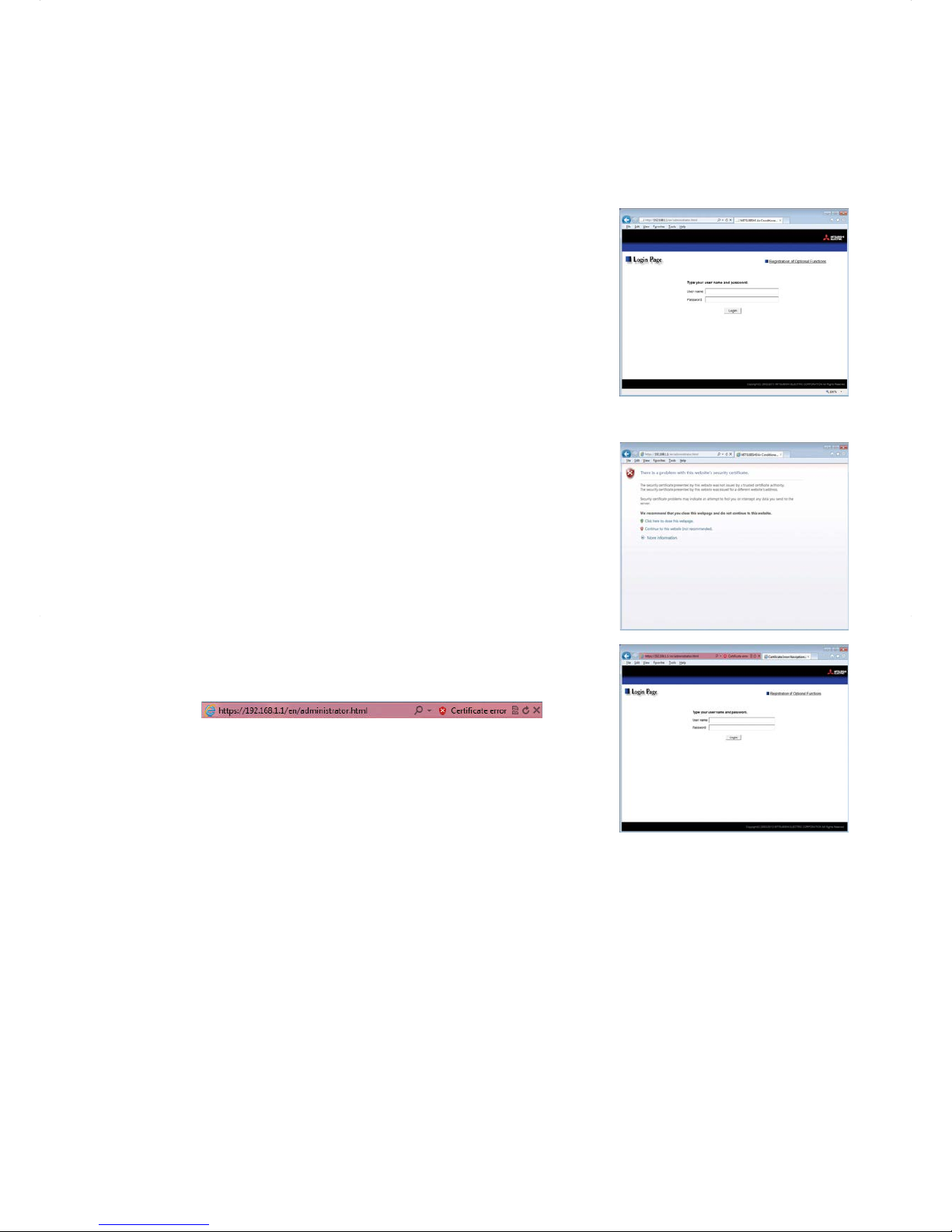
(1) Prefix the web address with [https], enter the rest of the address, and
press the [Enter] key.
https ://[IP Address of the EB-50]/administrator.html
Note: If the IP address of the EB-50 is [192.168.1.1], the web page address is
[https ://192.168.1.1/administrator.html].
The encrypted data communication will begin, and the Login screen
will appear.
If a security certificate error page appears instead of the Login
screen, go to step (2) below.
(2) If the security certificate is invalid, a security certificate error page (as
shown at right) will appear.
Click [Continue to this website (not recommended)].
(3) If the connection is successfully made, the Login screen will appear.
Note: Although the address bar will turn red and a message "Certificate
error" will appear, you can still access the Web browser.
Page 11
11
4. Monitor/Operation
This chapter explains how to monitor and operate the connected unit groups and to check the measurement
data, malfunctioning units, units whose filter sign is triggered, and AHC status.
4-1. Condition List
This section explains how to monitor the operation conditions of all groups collectively (see section 4-1-1) or
groups per block (see section 4-1-2) and also explains how to operate each group (see section 4-1-3), groups
per block (see section 4-1-4), or all groups collectively (see section 4-1-5).
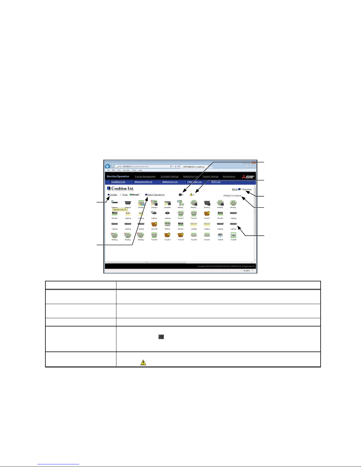
After login, the Overview display of the Condition List screen will appear, which shows the operation conditions
of all air conditioning unit groups, LOSSNAY unit (ventilator) groups, general equipment groups, and Air To Water
(PWFY) unit groups.
To access the Condition List screen from the other screen, click [Monitor/Operation] in the menu bar, and then
click [Condition List].
4-1-1. Checking the operation conditions of all groups
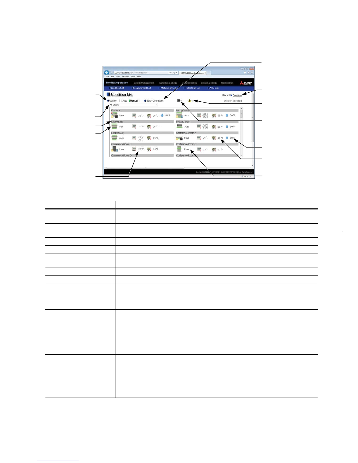
On the Overview display of the Condition List screen, the operation conditions of all groups can be monitored.
The operator can also check the unit malfunctions on this screen and prevent the units from being left on
unintentionally.
Block/Overview
Number of units whose
filter sign is turned on
Number of units in error
Weekly schedule number
Indicates the weekly
schedule that is currently
effective.
Group icons
The icons indicate the
operation conditions of
groups.
Click the icon to switch to
the operation screen.
Update
Click to show the most
recent operation conditions.
Batch Operations
Click to operate the units in
all groups at once.
Item Description
Block/Overview
Click [Block] to display the operation conditions of groups per block, and click [Overview]
to display the operation conditions of all groups.
Update
Click to show the most recent operation conditions.
When [Auto] is selected, the operation conditions are updated automatically every minute.
Batch Operations Click to operate the units in all groups at once. (See section 4-1-5.)
Number of units whose filter
sign is turned on
*1
The number of units under the control of EB-50 whose filter sign is currently turned on will
appear. Clicking "
" will bring up the Filter Sign List screen. (See section 4-4.)
Note: This item will not appear if the [Filter Sign Display] is set to [OFF] on the Basic System
settings screen, accessible via the Web Browser for Initial Settings.
Number of units in error
*1
The number of units under the control of EB-50 that are currently in error will appear.
Clicking "
" will bring up the Malfunction List screen. (See section 4-3.)
*1 The item will not appear if the number of units is "0."
Page 12
12
Item Description
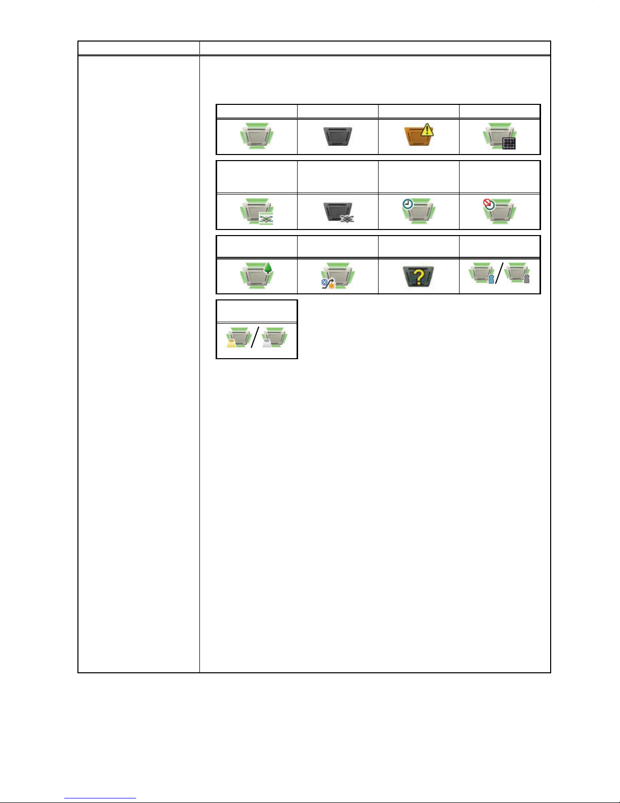
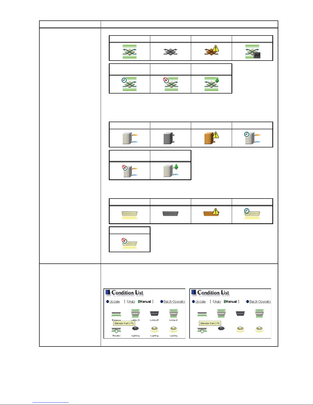
Group icons
Each group icon indicates the operation condition of the group. Move the cursor to the
icon to display its group name. Clicking the icon will bring up the operation screen.
The icons to indicate the operation conditions are shown below.
(1) Air conditioning unit group
ON OFF Error Filter sign ON
*1
Interlocked
LOSSNAY ON
*2 *8
Interlocked
LOSSNAY OFF
*3 *8
Schedule set
*4
HOLD ON
Energy-saving ON
*5
Setback ON
*11
Starting up
Occupied/Vacant
*6*7*8
(Blue) (Gray)
Bright/Dark
*9*10*11
(Yellow) (Gray)
Note: Besides the 4-way airflow unit icons, 2-way airflow or ceiling-suspended unit icons are
also available. Icons can be selected on the group settings screen, accessible via the Web
Browser for Initial Settings.
*1 Whether or not to display the filter sign can be set on the Basic System settings screen,
accessible via the Web Browser for Initial Settings.
*2 If the LOSSNAY unit is interlocked with the operation of Mr. Slim units, "Interlocked LOSSNAY
ON" icon will appear, even when the LOSSNAY unit is operated individually.
(Applicable M-NET adapter model: PAC-SF48/50/60/70/80/81MA-E)
*3 If a LOSSNAY unit is interlocked with the operation of indoor units in multiple groups, the
LOSSNAY unit may be in operation, even when the "Interlocked LOSSNAY OFF" icon is
displayed.
*4 If any schedule setting is applied to a DIDO controller whose prohibition setting is enabled
([Allow operations] is set to [No operations] on the group settings screen, accessible via
the Web Browser for Initial Settings), the "Schedule set" icon will appear, but the scheduled
operations will not be performed.
*5 The "Energy-saving ON" icon will appear while the Peak Cut control is performed on the group
or on the outdoor unit that is connected to the group.
*6 The Occupancy/Vacancy status icon will appear only when [Show occupancy icon], [Show
vacancy icon], or [Show both icons] is selected in the [Occupancy sensor display] section
under the [Display Format] section of the Basic System settings screen, accessible via the
Web Browser for Initial Settings.
*7 The Occupancy/Vacancy status icon will not appear if the remote controller in the group does
not have an occupancy sensor.
*8 The Occupancy/Vacancy status icon takes priority over the "Interlocked LOSSNAY ON" or
"Interlocked LOSSNAY OFF" icon.
*9 The Brightness/Darkness status icon will appear only when [Show bright symbol], [Show dark
symbol], or [Show both symbols] is selected in the [Brightness sensor display] section under
the [Display Format] section of the Basic System settings screen, accessible via the Web
Browser for Initial Settings.
*10 The Brightness/Darkness status icon will not appear if the remote controller in the group
does not have a brightness sensor.
*11 The "Setback ON" icon takes priority over the Brightness/Darkness status icon.
Page 13
13
Item Description
Group icons
(2) LOSSNAY unit (ventilator) group
ON OFF Error Filter sign ON
*1
Schedule set HOLD ON
Energy-saving ON
*2
*1 Whether or not to display the filter sign can be set on the Basic System settings screen,
accessible via the Web Browser for Initial Settings.
*2 The "Energy-saving ON" icon will appear while the Peak Cut control is performed on the
LOSSNAY unit group.
(3) Air To Water (PWFY) unit group
ON OFF Error Schedule set
HOLD ON
Energy-saving ON
*1
*1 The "Energy-saving ON" icon will appear while the Peak Cut control is performed on the Air To
Water (PWFY) unit group.
(4) General equipment group
ON OFF Error Schedule set
HOLD ON
Note: Besides the lighting icons, pump or card key icons are also available. The icon can be
selected on the group settings screen, accessible via the Web Browser for Initial Settings.
Group name
Only the first 8 characters will be visible under the icons. To display all characters, move
the cursor to the icon.
Note: Whether or not to display the group names can be set on the Basic System settings
screen, accessible via the Web Browser for Initial Settings.
Icons with group names Icons without group names
Page 14
14
4-1-2. Checking the operation conditions of the groups in a given block
In the Block display of the Condition List screen, select a block to display the operation conditions (such as
operation mode, set temperature, and room temperature) of the air conditioning unit groups, LOSSNAY unit
(ventilator) groups, Air To Water (PWFY) unit groups, and general equipment groups in the block.
Block/Overview
Number of units in error
Number of units whose
filter sign is turned on
Group icons
The icons indicate the
operation conditions of
groups.
Click the icon to switch to
the operation screen.
Update
Click to show the most
recent operation conditions.
Batch Operations
Click to operate the units in
all groups in a given block at
once.
Set temperature
Room temperature
Room humidity
Block selection
Operation mode
Group name
Item Description
Block/Overview
Click [Block] to display the operation conditions of groups per block, and click [Overview]
to display the operation conditions of all groups.
Update
Click to show the most recent operation conditions.
When [Auto] is selected, the operation conditions are updated automatically every minute.
Batch Operations Click to operate the units in all groups in a given block at once. (See section 4-1-4.)
Block selection Select a block you want to monitor.
Group icons
Each group icon indicates the operation condition of the group. Clicking the icon will bring
up the operation screen.
Group name The name of the group will appear.
Operation mode The operation mode of the group will appear.
Set temperature
The set temperature of the group will appear.
Note: For Air To Water (PWFY) unit groups, the set water temperature will appear.
Note: The temperature unit (°C or °F) can be selected on the Basic System settings screen,
accessible via the Web Browser for Initial Settings.
Room temperature
Indoor unit return air temperature will appear.
Note: The temperature shown may be different from the actual room temperature.
Note: Whether to show or hide the room temperature can be set on the Basic System settings
screen, accessible via the Web Browser for Initial Settings.
Note: For Air To Water (PWFY) unit groups, the current water temperature will appear.
Note: The temperature unit (°C or °F) can be selected on the Basic System settings screen,
accessible via the Web Browser for Initial Settings.
Room humidity
The reading of the indoor unit return air humidity or the humidity sensor on the ME remote
controller (Smart ME controller) will appear.
Note: The value will not appear if the indoor unit does not have a humidity measurement function.
Note: If a ME remote controller (Smart ME controller) is connected to the group and the built-in
humidity sensor is enabled, the reading of the sensor will appear.
Note: The indoor unit return air humidity has priority to be displayed over the reading of the
humidity sensor on the ME remote controller (Smart ME controller).
Page 15

15
Item Description
Number of units whose filter
sign is turned on
*1
The number of units under the control of EB-50 whose filter sign is currently turned on will
appear. Clicking "
" will bring up the Filter Sign List screen. (See section 4-4.)
Note: This item will not appear if the [Filter Sign Display] is set to [OFF] on the Basic System
settings screen, accessible via the Web Browser for Initial Settings.
Number of units in error
*1
The number of units under the control of EB-50 that are currently in error will appear.
Clicking "
" will bring up the Malfunction List screen. (See section 4-3.)
*1 The item will not appear if the number of units is "0."
Page 16
16
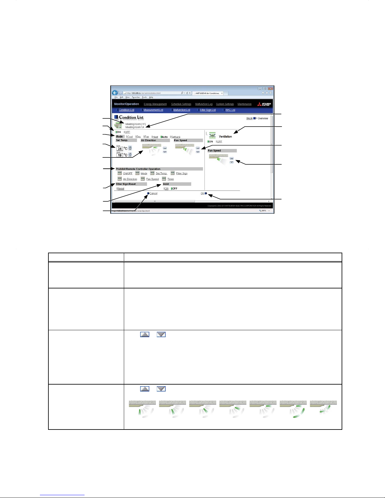
4-1-3. Operating the units in a given group
In the Overview display of the Condition List screen, click one of the group icons to display its operation settings
screen, which shows the current operation conditions. Change the desired settings and click [OK] to reflect the
changes. Click [Cancel] to return to the previous screen without making any changes.
Note: Only the ON/OFF operation is possible for general equipment groups. The general equipment whose prohibition
setting is enabled ([Allow operations] is set to [No operations] on the group settings screen, accessible via the
Web Browser for Initial Settings) cannot be operated.
Group name
Set temperature
ON/OFF
Block name
Interlocked LOSSNAY
ON/OFF
Fan speed of interlocked
LOSSNAY
Operation mode
Prohibit Remote Controller
Operation
Air direction
Filter Sign Reset
Hold
Cancel
Click to return to the
previous screen without
making any changes.
Fan speed
OK
Click to reflect the changes
made.
Item Description
ON/OFF
Click [ON] or [OFF] to turn on or off the units in a given group.
Note: Switching this switch will turn on or off the LOSSNAY unit as well that is interlocked with
the operation of indoor units in the group. To turn on or off the LOSSNAY unit only, use the
"Interlocked LOSSNAY ON/OFF" switch.
Operation mode
*1
Click the desired operation mode.
Air conditioning unit: Cool, Dry, Fan, Heat, Auto, Setback
LOSSNAY unit: Heat Recovery, Bypass, Auto
Air To Water (PWFY) unit: Heating, Heating ECO, Hot Water, Anti-freeze, Cooling
Note: Only the operation modes available for the unit model will appear.
Note: The Setback mode can be selected on the EB-50GU-A, but not on the EB-50GU-J.
Set temperature
*1
Click or to adjust the set temperature of the air conditioning unit or the Air To
Water (PWFY) unit.
Note: The settable temperature ranges depend on the unit model.
Note: If the indoor unit supports the dual set point function in the AUTO mode and when the
operation mode above is set to Auto or Setback, two set temperatures for Cool mode and
Heat mode can be set.
Note: The temperature unit (°C or °F) can be selected on the Basic System settings screen,
accessible via the Web Browser for Initial Settings.
Air Direction
*1
Click or to adjust the air direction.
(Mid 3) (Mid 2) (Mid 1) (Mid 0) (Horizontal) (Swing) (Auto)
Note: Available air directions depend on the unit model.
Page 17
17
Item Description
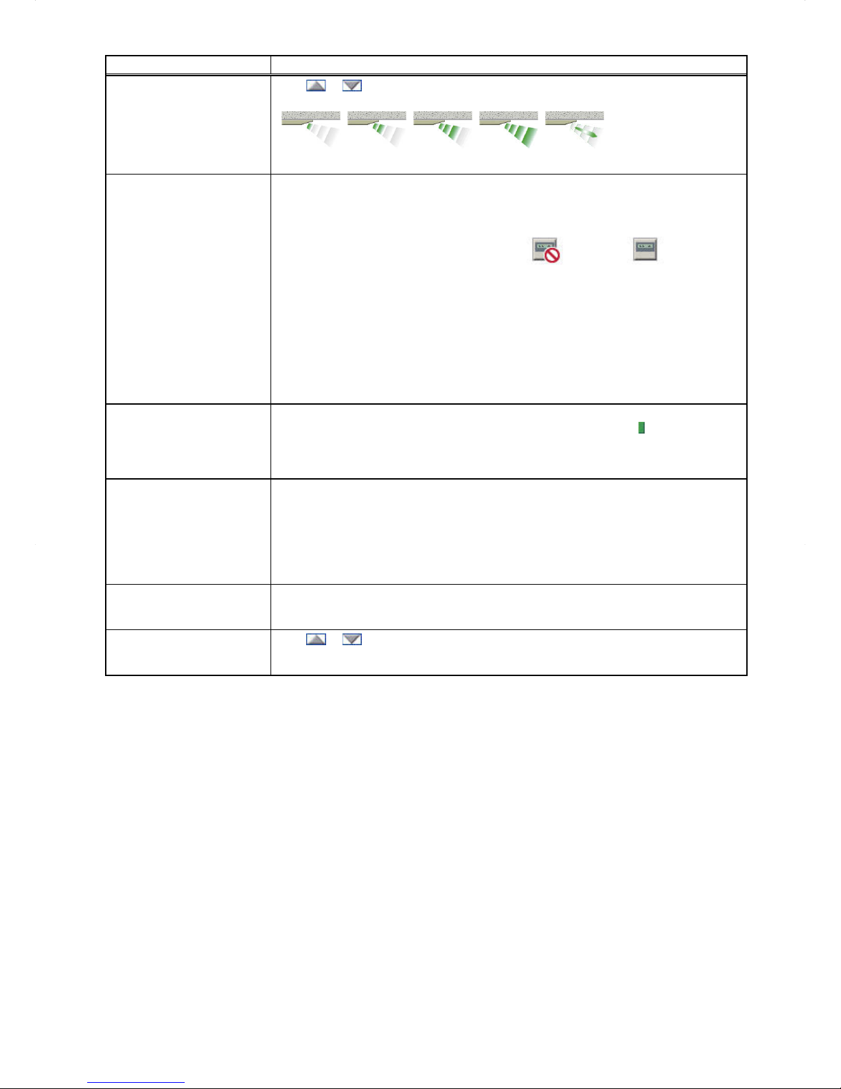
Fan Speed
*1
Click or to adjust the fan speed.
(Low) (Mid 2) (Mid 1) (High) (Auto)
Note: Available fan speeds depend on the unit model.
Prohibit Remote Controller
Operation
The following operations or setting change from the local remote controllers and the Web
Browser for User can be prohibited: ON/OFF, Operation mode, Set temperature, and
Filter sign reset.
Click the operation item [ON/OFF], [Mode], [Set Temp.], [Filter Sign], [Air Direction], [Fan
Speed], or [Timer] to switch the setting between
(Prohibit) or (Permit).
Note: For LOSSNAY unit (ventilator) groups, the item [Mode] or [Set Temp.] will not appear.
Note: [Air Direction], [Fan Speed], and [Timer] may not be displayed, depending on the unit
model.
Note: When the [ON/OFF] operation is prohibited and the "Automatic recovery after power failure"
switch on the indoor unit is set to "Turn off the power, or restore operation regardless of the
operation status immediately before power failure," the operation of the indoor unit will not
be restored, even when turned on after power restoration.
When the switch is set to "Turn off the power, or restore operation if the unit was in
operation immediately before power failure," the operation of the indoor unit will be
restored regardless of whether the [ON/OFF] operation is prohibited or not.
Refer to the indoor unit Installation Manual for details about switch settings.
Filter Sign Reset
Click [Reset] to switch between resetting and not resetting the filter sign. The rectangular
icon next to Reset will appear in yellow-green when it is set to Reset (
).
Note: If a filter sign in the group has not been triggered, then the item [Filter Sign Reset] will not
appear.
Note: Filter sign of LOSSNAY units will not be reset.
Hold
Click [ON] or [OFF] to enable/disable the Hold function. When the Hold function is
enabled, the scheduled operations are disabled.
Note: The operations that have been scheduled from the remote controller will also be disabled.
Note: [Hold type] can be specified on the Basic System settings screen, accessible via the Web
Browser for Initial Settings.
Note: The Hold function cannot be enabled on general equipments.
Note: The Hold function can be used on the EB-50GU-A, but not on the EB-50GU-J.
Interlocked LOSSNAY
ON/OFF
Click [ON] or [OFF] to turn on or off the interlocked LOSSNAY unit.
Note: For a group that is not connected to an interlocked LOSSNAY unit (ventilator), the item
[Interlocked ventilator ON/OFF] will not appear.
Fan speed of interlocked
LOSSNAY
Click
or to adjust the fan speed of the interlocked LOSSNAY unit (ventilator).
Note: For a group that is not connected to an interlocked LOSSNAY unit, the item [Fan speed of
interlocked LOSSNAY] will not appear.
*1 The item may not be displayed, depending on the unit model.
Page 18
18
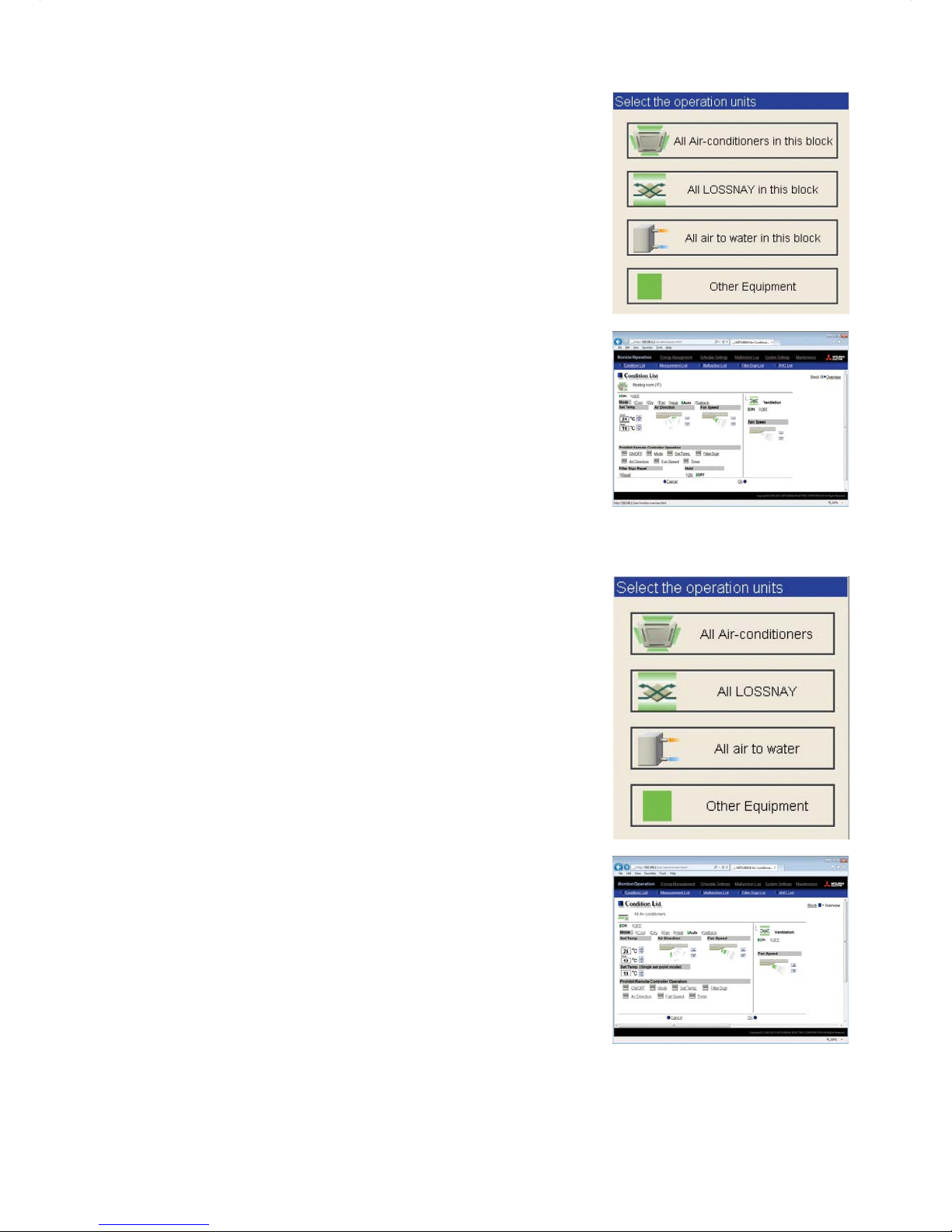
4-1-4. Operating the units in a given block
(1) In the Block display of the Condition List screen, select a block to
operate, and click [Batch Operations].
If air conditioner group, LOSSNA Y unit (ventilator) group, Air To Water
(PWFY) unit group, and general equipment group exist together in
the same block, a screen to select a group type will appear.
Click one of the group types to change its settings.
(2) On the operation settings screen, change the desired settings and
click [OK] to reflect the changes.
Click [Cancel] to return to the previous screen without making any
changes.
Note: When the filter sign is reset on this screen, the cumulative operation
time of all units will be reset, irrespective of whether or not the filter
sign was triggered. Reset the filter sign on this screen when the
filters of all units were cleaned at once.
4-1-5. Operating the units in all groups
(1) In the Overview display of the Condition List screen, click [Batch
Operations]. If air conditioner group, LOSSNAY unit (ventilator)
group, Air To Water (PWFY) unit group, and general equipment group
exist together in the same system, a screen to select a group type
will appear.
Click one of the group types to change its settings.
(2) On the operation settings screen, change the desired settings and
click [OK] to reflect the changes.
Click [Cancel] to return to the previous screen without making any
changes.
Note: When the filter sign is reset on this screen, the cumulative operation
time of all units will be reset, irrespective of whether or not the filter
sign was triggered. Reset the filter sign on this screen when the
filters of all units were cleaned at once.
Page 19
19
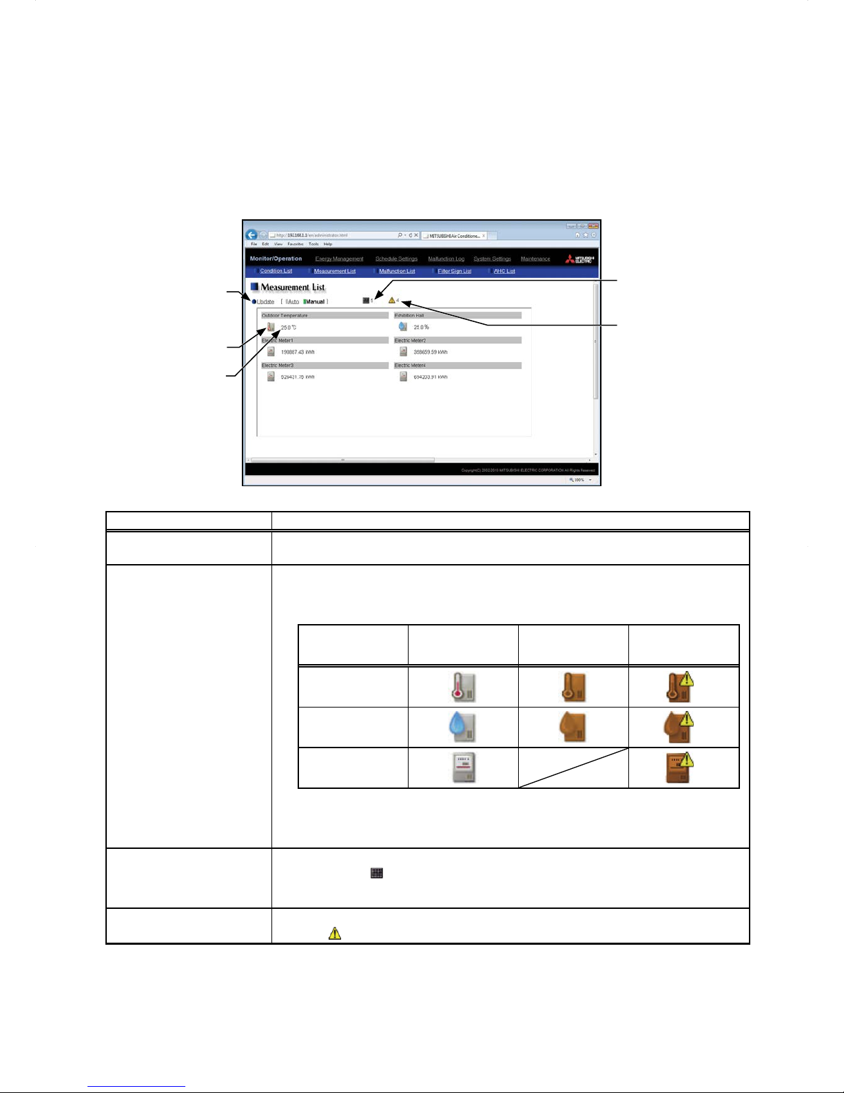
4-2. Measurement List
This section explains how to check the measurement data of the temperature sensors, humidity sensors, and
metering devices.
Click [Monitor/Operation] in the menu bar, and then click [Measurement List] to access the Measurement List
screen.
Note: An AI controller (PAC-YG63MCA), a commercially available temperature sensor, and a humidity sensor are
required to measure the temperature and humidity.
Note: A PI controller (PAC-YG60MCA) and a commercially available metering devices are required to measure the
electric, water, heat, and gas consumptions.
Measurement item
Update
Click to show the most
recent measurement data.
Measurement value
Number of units whose
filter sign is turned on
Number of units in error
Item Description
Update
Click to show the most recent measurement data.
When [Auto] is selected, the measurement data is updated automatically every minute.
Measurement value
The current measurement values will appear.
Note: The following icons are used to indicate the measuring devices. Icons will appear in orange
when the measurement value reaches the upper or lower alarm threshold value that has
been set on the Measurement screen, accessible via the Web Browser for Initial Settings.
Normal
Upper/lower alarm
threshold value is
reached.
Communication
error
Temperature sensor
*1
Humidity sensor
*1
Metering device
*2
*1 When there is a communication error, the measurement value of the temperature or humidity
sensor will be "--."
*2 When there is a communication error, the measurement value of the metering device will be
the measured value immediately before the error detection.
Number of units whose filter
sign is turned on
*1
The number of units under the control of EB-50 whose filter sign is currently turned on will
appear. Clicking "
" will bring up the Filter Sign List screen. (See section 4-4.)
Note: This item will not appear if the [Filter Sign Display] is set to [OFF] on the Basic System
settings screen, accessible via the Web Browser for Initial Settings.
Number of units in error
*1
The number of units under the control of EB-50 that are currently in error will appear.
Clicking "
" will bring up the Malfunction List screen. (See section 4-3.)
*1 The item will not appear if the number of units is "0."
Page 20
20
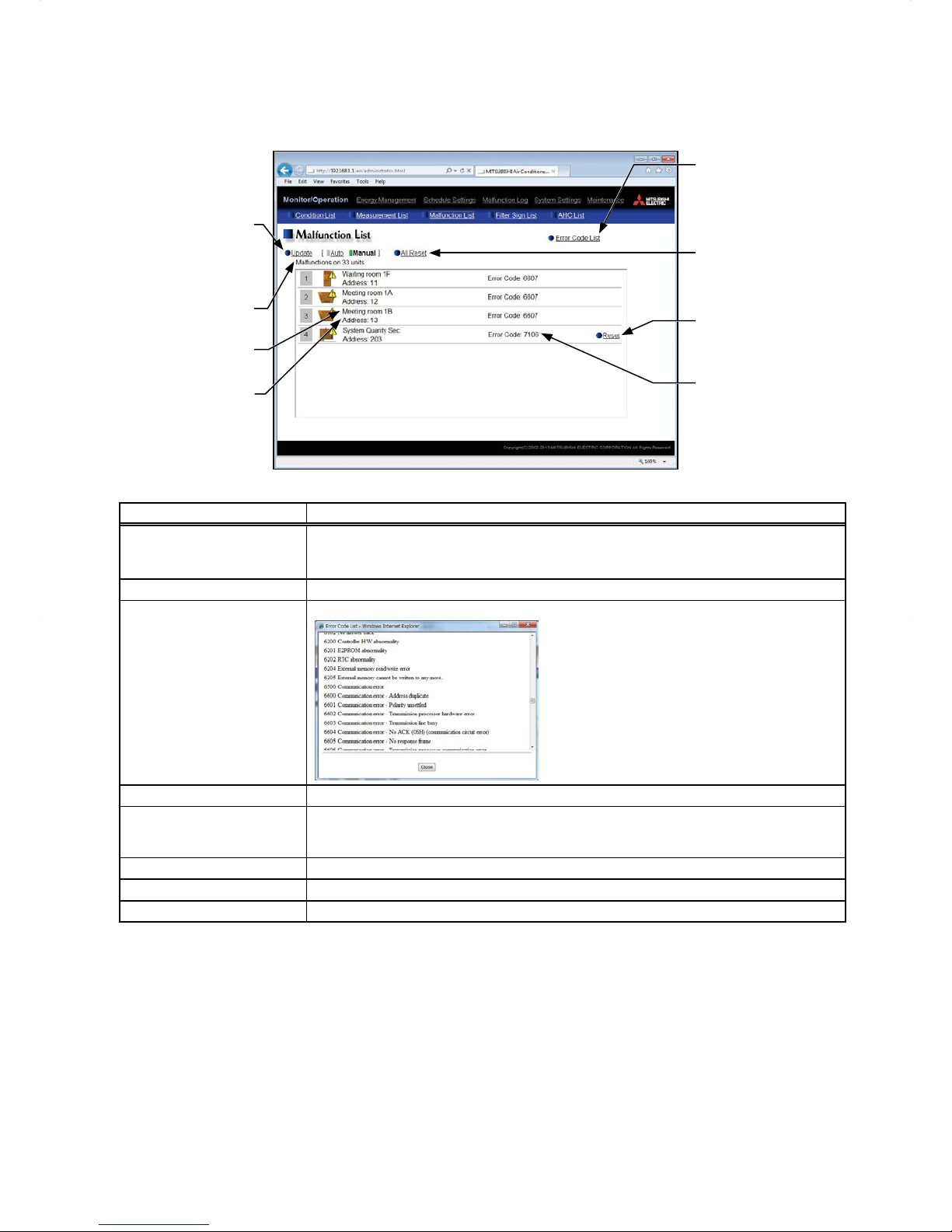
4-3. Malfunction List
Click [Monitor/Operation] in the menu bar, and then click [Malfunction List] to access the Malfunction List screen.
A list of units that are currently malfunctioning will appear.
Number of units in error
Update
Click to show the most
recent malfunction
conditions.
All Reset
Click to reset all errors at
once.
Group name
Unit address
Error code
Reset
Click to reset each AHC
error.
Error Code List
Click to display the list
of error codes and their
definitions.
Item Description
Update
Click to show the most recent malfunction conditions.
When [Auto] is selected, the malfunction conditions are updated automatically every
minute.
All Reset Click to reset all errors at once.
Error Code List
Click to display the list of error codes and their definitions.
Number of units in error The number of malfunctioning units will appear.
Group name
The name of the group that the unit in error belongs to will appear.
Note: The group name will be blank if the unit in error is a unit that does not belong to any group,
such as an outdoor unit or a system controller.
Unit address The address of the unit in error will appear.
Error code The error code that corresponds to the error will appear.
Reset Click to reset each AHC error.
Page 21

21
Types of units in error and the units that will stop when errors are reset
Types of units in error and the units that will stop
Units in error Units that will stop
EB-50 None
Outdoor unit All indoor units that are connected to the outdoor unit in error
Indoor unit Indoor unit in error and all other indoor units in the same group
ME (MA) remote controller All indoor units that are connected to the remote controller in error
System controller All indoor units that are connected to the system controller in error
Advanced HVAC CONTROLLER None
Interlocked LOSSNAY unit Indoor units with which the LOSSNAY unit in error is interlocked
Air To Water (PWFY) unit
Air To Water (PWFY) unit in error and all other Air To Water (PWFY) units in the same
group
DIDO controller (PAC-YG66DCA) None
Example of units in error and the units that will stop
Indoor unit
[2]
AHC
[202]
Indoor unit
[1]
Indoor unit
[3]
Indoor unit
[4]
Indoor unit
[5]
Air To Water (PWFY) unit
[7]
DIDO controller (PAC-YG66DCA)
[8]
Outdoor unit
[51]
Outdoor unit
[53]
Outdoor unit
[55]
Outdoor unit
[57]
EB-50
[0]
ME remote controller
[101]
System controller
[201]
LOSSNAY unit
[6]
Group 1
Group 2
Units in error Units that will stop
EB-50 [0] None
Outdoor unit [51] Indoor unit [1], Indoor unit [2]
Outdoor unit [53] Indoor unit [3], Indoor unit [4], Indoor unit [5]
Outdoor unit [57] Air To Water (PWFY) unit [7]
Indoor unit [1] Indoor unit [1], Indoor unit [2]
Indoor unit [3] Indoor unit [3]
Indoor unit [5] Indoor unit [4], Indoor unit [5]
LOSSNAY unit [6] Indoor unit [5]
Air To Water (PWFY) unit [7] Air To Water (PWFY) unit [7]
ME remote controller [101] Indoor unit [1]
System controller [201] Indoor unit [1], Indoor unit [3], Indoor unit [4]
Advanced HVAC CONTROLLER [202] None
DIDO controller (PAC-YG66DCA) [8] None
Page 22
22
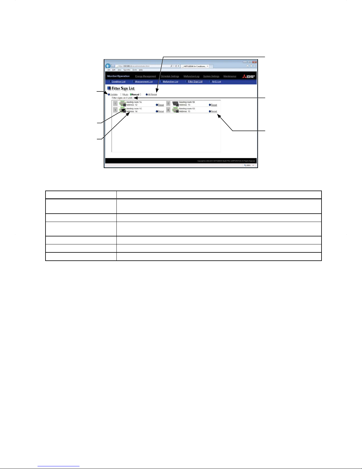
4-4. Filter Sign List
A list of units whose filter sign is turned on can be displayed.
Click [Monitor/Operation] in the menu bar, and then click [Filter Sign List] to access the Filter Sign List screen.
Unit address
Group name
Update
Click to show the most
recent conditions.
Reset
Click to reset the filter sign.
Number of units whose
filter sign is turned on
All Reset
Click to reset all filter signs
at once.
Item Description
Update
Click to show the most recent conditions.
When [Auto] is selected, the conditions are updated automatically every minute.
All Reset Click to reset all filter signs at once.
Number of units whose filter
sign is turned on
The number of units whose filter sign is currently turned on will appear.
Group name The name of the group that the unit belongs to will appear.
Unit address The address of the unit whose filter sign is turned on will appear.
Reset Click to reset each filter sign.
Page 23

23
4-5. AHC List
On the AHC List screen, the status of input and output ports of each Advanced HVAC CONTROLLER (AHC) can
be monitored.
Click [Monitor/Operation] in the menu bar, and then click [AHC List] to access the AHC List screen.
The port names and their status of each AHC will appear.
AHC address
AHC icon
Update
Click to show the most
recent conditions.
Status of related
equipment
Number of units in error
Output status
Number of units whose
filter sign is turned on
Input status
Item Description
Update
Click to show the most recent conditions.
When [Auto] is selected, the conditions are updated automatically every minute.
AHC icon
The following icons indicate the AHC status.
: Normal
: A communication error is occurring or an error signal has been input to the
AHC.
AHC address The address of the connected AHC will appear.
Input status
[Input port code
*
+ Input port name + Input status] will appear.
* DI1–DI15 (Digital input), EI1–EI4 (Extended digital input), AI1–AI8 (Analog input)
Note: The status of the unused ports will not appear.
Note: If a communication error occurs with AHC, no port information will appear.
Output status
[Output port code
*
+ Output port name + Output status] will appear.
* DO1–DO9 (Digital output), EO1–EO4 (Extended digital output), AO1–AO2 (Analog output)
Note: The status of the unused ports will not appear.
Note: If a communication error occurs with AHC, no port information will appear.
Status of related equipment
Click to display the status of the equipment that are used to control the equipments that
are connected to the AHC.
Page 24

24
Item Description
Number of units whose filter
sign is turned on
*1
The number of units under the control of EB-50 whose filter sign is currently turned on will
appear. Clicking "
" will bring up the Filter Sign List screen. (See section 4-4.)
Note: This item will not appear if the [Filter Sign Display] is set to [OFF] on the Basic System
settings screen, accessible via the Web Browser for Initial Settings.
Number of units in error
*1
The number of units under the control of EB-50 that are currently in error will appear.
Clicking "
" will bring up the Malfunction List screen. (See section 4-3.)
*1 The item will not appear if the number of units is "0."
Page 25

25
5. Energy Management
5-1. Energy Use Status
On the Energy Use Status screen, the energy-control-related status, such as electric energy consumption,
operation time, and outdoor temperature, can be displayed in a graph. Operators can check the detailed status
of given indoor units by specifying the date to display the data per group, block, or unit address. Also, the status
of other indoor units can be displayed at the same time for comparison.
Click [Energy Management] in the menu bar, and then click [Energy Use Status] to access the Energy Use
Status screen.
Note: A separate license is required, depending on the selected date range, display range, and display item.
Display item
Download
Click to export the data in
the CSV format.
Date to display the data
Display range
Display target
Graph region
Comparison date
Refresh screen
Click to show the graph
created based on the
specified criteria.
Comparison target
Date range
Item Description
Date range
Select [Day], [Month], or [Year].
Note: When [Day] is selected, the data for each hour between 0:00 and 24:00 of the specified date will
appear in the graph.
When [Month] is selected, the data for each day between the 1st and 31st of the specified month
will appear in the graph.
When [Year] is selected, the data for each month between January and December of the specified
year will appear in the graph.
Note: Only the data for the period during which the EB-50 was powered on will appear in the graph. The
data for the period during which the EB-50 was powered off will not appear in the graph.
Display range Select [Block], [Group], or [Address] to display its data.
Display target
Select a block name, group name, or address number to display its data.
Note: The selectable items vary, depending on the item selected in the [Display range] field.
Date to display the
data
Specify a date to display the data.
Note: When [Day] is selected as a Date range, specify "yyyy/mm/dd" from the current month or the last
24 months.
When [Month] is selected as a Date range, specify "yyyy/mm" from the current month or the last 24
months.
When [Year] is selected as a Date range, specify "yyyy" from the current year or the last 4 years.
Note: The date will appear in the format that has been set on the Basic System settings screen,
accessible via the Web Browser for Initial Settings.
Comparison target
Select a block name, group name, or address to display the comparison data.
Note: The selectable items vary, depending on the item selected in the [Display range] field.
Comparison date
Specify a date to display the comparison data.
Note: The same rule as for the "Date to display the data" apply.
Note: The date will appear in the format that has been set on the Basic System settings screen,
accessible via the Web Browser for Initial Settings.
Refresh screen
Click to show the graph created based on the specified criteria.
Note: No graph will appear if no data that meet the specified criteria exist.
Page 26

26
Item Description
Display item
Select an item in the top row to display its data in the bar graph, and select an item in the bottom
row to display its data in the line graph.
Note: The selectable items vary, depending on the items selected in the [Display range] and [Display
target] fields.
Display items for bar graph
Display target Display item
Display range
Address Group Block
Indoor unit
Electric Energy
*3
V
*1
V
*1
V
*1
Fan operation time
*4
V
*1
V
*1
-
Thermo-ON time (Total)
*4
V
*1
V
*1
-
Thermo-ON time (Cool)
*4
V
*1
V
*1
-
Thermo-ON time (Heat)
*4
V
*1
V
*1
-
MCP
(PI controller)
Name of the metering device
1
V
*2
- -
Name of the metering device
2
V
*2
- -
Name of the metering device
3
V
*2
- -
Name of the metering device
4
V
*2
- -
V: Item that can be displayed in the graph
*1 "Energy Management License Pack" is required.
*2 If "Energy Management License Pack" has not been registered, only [Day] is available for selection as a
Date range. To select [Month] or [Year], "Energy Management License Pack" is required.
*3 The electric energy consumed by indoor units will appear in the graph. The values are apportioned
based on the setting for [Indoor unit operation apportioning mode] that has been made on the Energy
Management Settings screen, accessible via the Web Browser for Initial Settings.
*4 The indoor unit's cumulative operation time for the selected item will appear in the graph.
• [FAN operation time] is the cumulative duration of time in which the indoor unit is powered on.
• [Thermo-ON time (Total/Cool/Heat)] is the cumulative duration of time in which the indoor unit and the
compressor are powered on. (Cool: when the Cool mode is selected; Heat: when the Heat mode is
selected; Total: when either mode is selected)
Page 27

27
Item Description
Display item
Display items for line graph
Display target Display item
Display range
Address Group Block
- Outdoor Temp.
*5
V
*2
V
*2
V
*2
Indoor unit
Target value - - V
*1*3
Set Temp. for cool
*5
V
*3
V
*3
-
Set Temp. for heat
*5
V
*3
V
*3
-
Room Temp.
*5
V
*3
V
*3
-
MCT
(AI controller)
*5
Name of the temperature
sensor 1 or humidity sensor 1
V
*4
- -
Name of the temperature
sensor 2 or humidity sensor 2
V
*4
- -
AHC
*5
Name of the
temperature sensor 1
V
*3
- -
Name of the
temperature sensor 2
V
*3
- -
V: Item that can be displayed in the graph
*1 The target values will appear in the graph when the target electric energy values are specified on the
Target Value Setting screen and when the electricity meter is selected in the [Indoor unit electricity meter]
section on the Energy Management Settings screen, accessible via the Web Browser for Initial Settings.
*2 Selectable only when the outdoor temperature sensor is selected in the [External Temperature Sensor]
section on the Energy Management Settings screen, accessible via the Web Browser for Initial Settings.
*3 "Energy Management License Pack" is required.
*4 If the "Energy Management License Pack" has not been registered, only [Day] is available for selection as
a Date range. To select [Month] or [Year], "Energy Management License Pack" is required.
*5 When [Day] is selected as a Date range, the temperature values obtained every hour will appear. When
[Month] is selected, the average daily temperature values will appear. When [Year] is selected, the
average monthly temperature values will appear.
Graph region
The display target's data and the comparison target's data will appear in a bar graph and a line
graph.
Display target Comparison target Target value
Bar graph
(Brown) (Yellow)
Line graph
(Orange) (Blue) (Red)
Note: If no item is selected in the [Comparison target] field, only the data of the item selected in the [Display
target] field will appear in the graph.
Note: The data for a certain period of time may not appear if it does not exist due to the changes of the
daylight saving time setting or current time setting.
If the data overlap for a certain period of time due to the time overlap that was occurred when
daylight saving ended or the current time setting was changed, the newer data will appear in the
graph.
Page 28

28
Item Description
Download
Click [Download] to export the displayed measurement data in the CSV format.
The CSV file name and file format will vary as shown below, depending on the selected date
range.
■ File name
<When any item in the [Comparison target] field is selected>
Date range: Day
EM_DailyTrend_[yyyy]-[mm]-[dd]_[Display target]_[YYYY]-[MM]-[DD]_[Comparison target]_
[Bar graph type]_[Line graph type].csv
Date range: Month
EM_MonthlyTrend_[yyyy]-[mm]_[Display target]_[YYYY]-[MM]_[Comparison target]_[Bar
graph type]_[Line graph type].csv
Date range: Year
EM_AnnualTrend_[yyyy]_[Display target]_[YYYY]_[Comparison target]_[Bar graph type]_
[Line graph type].csv
<When no item in the [Comparison target] field is selected>
Date range: Day
EM_DailyTrend_[yyyy]-[mm]-[dd]_[Display target] _[Bar graph type]_[Line graph type].csv
Date range: Month
EM_MonthlyTrend_[yyyy]-[mm]_[Display target] _[Bar graph type]_[Line graph type].csv
Date range: Year
EM_AnnualTrend_[yyyy]_[Display target]_ [Bar graph type]_[Line graph type].csv
File-name contents Format
[yyyy] The year specified in the [Date to display the data] field
[mm] The month specified in the [Date to display the data] field
[dd] The date specified in the [Date to display the data] field
[Display target]
Address "A" + M-NET address (000–250) + "_" + Sensor No. (00–04)
Group "G" + Group No. (001–050) + "_" + "00"
Block "B" + Block No. (001–050, 999
*1)
+ "_" + "00"
[YYYY] The year specified in the [Comparison date] field
[MM] The month specified in the [Comparison date] field
[DD] The date specified in the [Comparison date] field
[Comparison target]
Address "A" + M-NET address (000–250) + "_" + Sensor No. (00–04)
Group "G" + Group No. (001–050) + "_" + "00"
Block "B" + Block No. (001–050, 999
*1)
+ "_" + "00"
[Bar graph type]
B01: Electric energy (Indoor unit)
B02: Fan operation time
B03: Thermo-ON time (Total)
B04: Thermo-ON time (Cool)
B05: Thermo-ON time (Heat)
B06: MCP electric energy
B08: MCP water quantity
B09: MCP heat quantity
[Line graph type]
L01: Set temperature (Cool)
L02: Set temperature (Heat)
L03: Room temperature
L04: MCT temperature
L05: AHC temperature
L06: Outdoor temperature
L08: MCT humidity
*1 "B999" = Total of all blocks
Page 29

29
Item Description
Download
■ File format
Row Item
Date
range
Format
1st File Type
Day 401
Month 402
Year 403
2nd Date
Day dd/mm/yyyy:DD/MM/YYYY
*1
Month mm/yyyy:MM/YYYY
*1
Year yyyy:YYYY
*1
3rd Target
"Block" + Block number (Display target)/
"Block" + Block number (Comparison target)
4th
Measurement
item
Day "Time",
"Block" + Block number (Display target) (Bar) + "–" +
Display item (Bar), "Block" + Block number (Comparison
target) (Bar) + "–" + Display item (Bar), "Target electric
energy(kWh)"
*2*3
, "Block" + Block number (Display target)
(Line) + "–" + Display item (Line), "Block" + Block number
(Comparison target) (Line) + "–" + Display item (Line)
Month "Day",
Year "Month",
5th–
*5
Data
*4
Day hh:mm,
Data value (Bar), Comparison data value (Bar), Target
electric energy value
*2*3
, Data value (Line), Comparison
data value (Line)
Month dd,
Year mm,
*1 The date will appear in the format that has been set on the Basic System settings screen, accessible via
the Web Browser for Initial Settings.
*2 "Target electric energy(kWh)" and the target electric energy value will appear only when the data is
displayed in the graph.
*3 "Target electric energy(kWh)" and the target electric energy value will not appear if [Day] is selected as a
Date range.
*4 The separator character and decimal point character selected on the Measurement screen (accessible via
the Web Browser for Initial Settings) will be used to the data.
*5 The number of rows varies with the selected date range. (Day: 5th–28th; Month: 5th–35th; Year: 5th–16th)
Page 30

30
Item Description
Download
■ File sample
Date range: Day
401
2013/08/19:2012/06/01
Block1/Block5
Time,Block1 - Indoor Unit Electric Energy,Block5 - Indoor Unit Electric Energy,Block1 - Outdoor Temp.,Block5 - Outdoor Temp.
00:00,0.61,0.25,23.2,17.8
01:00,0.65,0.51,23.1,17.6
02:00,0.66,0.48,22.1,18.1
03:00,0.66,0.58,23.3,18.2
04:00,0.63,0.47,24.5,17.5
05:00,0.59,0.39,26.8,19.1
06:00,0.52,0.52,28.1,22.1
:
23:00,0.59,0.23,23.4,17.1
Date range: Month
402
2013/08:2012/06
Block1/Block5
Day,Block1 - Indoor Unit Electric Energy,Block5 - Indoor Unit Electric Energy,Target electric energy (kWh),Block1 - Outdoor
Temp.,Block5 - Outdoor Temp.
01,24.69,8.74,22,26.2,17.9
02,25.31,8.22,22,27,17.4
03,12.36,22.33,10,25.2,16.6
04,10.37,21.36,10,25.1,19.3
05,27.02,17.55,22,27.7,20.5
06,24.55,16.58,22,26.3,19
07,24.69,17.96,22,24.9,18.9
:
31,13.2,20.22,10,27.3,20.2
Date range: Year
403
2013:2012
Block1/Block5
Month,Block1 - Indoor Unit Electric Energy,Block5 - Indoor Unit Electric Energy,Target electric energy (kWh),Block1 - Outdoor
Temp.,Block5 - Outdoor Temp.
01,675.17,661.93,600,0.4,0.5
02,697.38,683.71,700,0.3,3.2
03,528.63,518.26,400,4.5,3.8
04,403.67,395.75,500,9.8,10
05,420.28,412.04,500,15.9,15.6
06,450.33,477.88,500,18.2,20.6
07,594.13,582.48,550,22.8,24.8
:
12,602.58,590.76,550,3.3,3.4
Page 31

31
5-2. Ranking
On the Ranking screen, the rankings in electric energy consumption and the fan operation time of given indoor
units can be displayed per block, group, and unit in descending order in the bar graph.
Click [Energy Management] in the menu bar, and then click [Ranking] to access the Ranking screen.
Note: "Energy Management License Pack" is required to access the Ranking screen.
Display item
Download
Click to export the data in
the CSV format.
Date
Display range
Graph region
Refresh screen
Click to show the graph
created based on the
specified criteria.
Date range
Item Description
Date range Select [Day], [Month], or [Year].
Display range Select [Block], [Group], or [Address] to display its data in the ranking graph.
Date
Specify a date to display the data in the ranking graph.
Note: When [Day] is selected as a Date range, specify "yyyy/mm/dd" from the current month or the last
24 months.
When [Month] is selected as a Date range, specify "yyyy/mm" from the current month or the last 24
months.
When [Year] is selected as a Date range, specify "yyyy" from the current year or the last 4 years.
Note: Only the data for the period during which the EB-50 was powered on will appear in the graph. The
data for the period during which the EB-50 was powered off will not appear in the graph.
Display item
Select an item to display its data in the ranking graph.
Note: The selectable items vary, depending on the items selected in the [Display range] field.
Display items
Display item
Display range
Address Group Block
Electric Energy (kWh) V V V
Fan operation time (min) V V Thermo-ON time (Total) (min) V V Thermo-ON time (Cool) (min) V V Thermo-ON time (Heat) (min) V V Target value (kWh)
-
- V
*1
V: Item that can be displayed in the graph
*1 The target values will appear in the graph when the target electric energy values are specified on the
Target Value Setting screen and when the electricity meter is selected in the [Indoor unit electricity meter]
section on the Energy Management Settings screen, accessible via the Web Browser for Initial Settings.
Refresh screen
Click to show the graph created based on the specified criteria.
Note: No graph will appear if no data that meet the specified criteria exist.
Graph region Ranking graph will appear in descending order of the value of the selected display item.
Page 32

32
Item Description
Download
Click [Download] to export the displayed measurement data in the CSV format.
The CSV file name and file format will vary as shown below, depending on the selected date
range.
■ File name
Date range: Day
EM_DailyRanking_[yyyy]-[mm]-[dd]_[Display range]_[Ranking graph type].csv
Date range: Month
EM_MonthlyRanking_[yyyy]-[mm]_[Display range] _[Ranking graph type].csv
Date range: Year
EM_AnnualRanking_[yyyy]_[Display range]_[Ranking graph type].csv
File-name contents Format
[yyyy] The year specified in the [Date] field
[mm] The month specified in the [Date] field
[dd] The date specified in the [Date] field
[Display range]
Address A999
Group G999
Block B999
[Ranking graph type]
B01: Electric energy (Indoor unit)
B02: Fan operation time
B03: Thermo-ON time (Total)
B04: Thermo-ON time (Cool)
B05: Thermo-ON time (Heat)
■ File format
Row Item
Date
range
Format
1st File T ype
Day 404
Month 405
Year 406
2nd Date
Day dd/mm/yyyy
*1
Month mm/yyyy
*1
Year yyyy
*1
3rd Display range
Address "All addresses"
Group "All groups"
Block "All blocks"
4th Measurement item
Address "Address number", Display item
Group "Group name", Display item
Block "Block name", Display item, "Target electric energy(kWh)"
*2
5th–
28th
Data
*3
Address Address number, Data value
Group "Group" + Group number, Data value
Block
"Block" + Block number, Data value, Target electric energy
value
*3
*1 The date will appear in the format that has been set on the Basic System settings screen, accessible via
the Web Browser for Initial Settings.
*2 "Target electric energy(kWh)" and the target electric energy value will appear only when the data is
displayed in the graph.
*3 The separator character and decimal point character selected on the Measurement screen (accessible via
the Web Browser for Initial Settings) will be used to the data.
Page 33

33
Item Description
Download
■ File sample
Date range: Day
404
01/23/2013
All blocks
Block name,Indoor Unit Electric Energy,Target electric energy (kWh)
Block1,25.19,21.2
Block5,19.58,18.13
Unregistered Blocks,17.01,19.73
Block3,11.2,16.9
Block6,6.19,5.24
Block2,5.98,10.96
Date range: Month
405
01/2013
All blocks
Block name,Indoor Unit Electric Energy,Target electric energy (kWh)
Block1,780.89,657.2
Block5,606.98,562.03
Unregistered Blocks,527.31,611.63
Block3,347.2,523.9
Block6,191.89,162.44
Block2,185.38,339.76
Date range: Year
406
2013
All blocks
Block name,Indoor Unit Electric Energy,Target electric energy (kWh)
Block1,9370.68,7886.4
Block5,7283.76,6744.36
Unregistered Blocks,6327.72,7339.56
Block3,4166.4,6286.8
Block6,2302.68,1949.28
Block2,2224.56,4077.12
Page 34

34
5-3. Target Value Setting
This section explains how to set the target electric energy consumption values for the entire system for the
current year, each month, each day of the week, and each block. The set values will be displayed in the graph on
the Energy Use Status screen (see section 5-1) and the Ranking screen (see section 5-2).
Click [Energy Management] in the menu bar, and then click [Target Value Setting] to access the Target Value
Setting screen.
Under the [Total target value] section, the items [Annual target], [Monthly target], and [Usage ratio for each day of
the week] will appear. Set the annual target electric energy, usage ratio for each month, and usage ratio for each
day of the week to automatically calculate the monthly target electric energy.
Under the [Target value for each block] section, set the usage ratio for each block to automatically calculate the
annual target electric energy for each block.
Important: The target value settings must be made after all units have been started up.
The settings that have been saved while one or more units are starting up may be lost.
Monthly target electric
energy
Usage ratio for each
month
Usage ratio for each day
of the week
Refresh
Click to import the settings
from EB-50.
Comparison with previous
year
Annual target electric
energy
Auto calc.
Save Settings
Click to send the settings to
EB-50.
Usage ratio for each block
Block name
Annual target electric
energy for each block
Item Description
Annual target electric energy
Enter the annual target electric energy consumption value.
Note: The value must be between 0 and 4294967 kWh.
Note: If the ratio is entered in the [Comparison with previous year] field, the annual target electric
energy will be calculated automatically, based on the electric energy consumption data of
the previous year.
Comparison with previous
year
Enter the ratio of the annual target electric energy of the current year to the electric
energy consumed in the previous year.
Note: The ratio must be between 0.0 and 999.9%.
Note: If the value is entered in the [Annual target electric energy] field, the ratio will be calculated
automatically based on the electric energy consumption data of the previous year.
Monthly target electric
energy
The target electric energy value for each month will appear.
Note: The values cannot be entered. The values will be calculated automatically, based on the
ratios entered in the [Usage ratio for each month] field.
Page 35

35
Item Description
Usage ratio for each month
Enter the target usage ratios of the annual electric energy for each month.
Note: Each ratio must be between 0 and 100%.
Note: The total of the ratios must be 100%. If the total is not 100%, a window that shows the
current total value as shown below will appear and the setting will not be saved.
Note: When the ratios are entered, the values in the [Monthly target electric energy] field will be
calculated automatically, based on the value in the [Annual target electric energy] field.
Usage ratio for each day of
the week
Enter the target usage ratios of the electric energy for each day of the week.
Note: The total of the ratios must be 100%. If the total is not 100%, a window that shows the
current total value as shown below will appear and the setting will not be saved.
Note: When the ratios are entered, the values in the [Monthly target electric energy] field may
change after being recalculated.
Block name
The names of all the registered blocks will appear.
Note: If the block name has not been registered, ["Block" + block number] will appear.
Usage ratio for each block
Enter the target usage ratios of the electric energy for each block.
Note: The ratios cannot be entered if the [Auto calc.] checkbox is checked. To enter the desired
ratios, uncheck the checkbox.
Note: The total of the ratios must be 100%. If the total is not 100%, a window that shows the
current total value as shown below will appear and the setting will not be saved.
Auto calc.
Check the checkbox to automatically calculate the usage ratio of the electric energy and
the annual target electric energy for each block based on the indoor unit capacity.
Annual target electric energy
for each block
The annual target electric energy for each block will appear after being calculated based
on the ratios in the [Usage ratio for each block] field and the value entered in the [Annual
target electric energy] field.
Page 36

36
5-4. Peakcut Control Status
This section explains how to check the Peakcut control status.
Click [Energy Management] in the menu bar, and then click [Peakcut Control Status] to access the Peakcut
Control Status screen.
The average electric power consumption (kW) and the control level will appear in the graph. The measurement
data can be exported in a CSV format from the screen.
Average electric power
Control level
Download
Click to export the data in
the CSV format.
Update
Click to show the most
recent measurement data.
Measurement date
Item Description
Update Click to show the most recent measurement data.
Measurement date
Select the measurement date.
Note: The data of the past three days including the current day can be displayed.
Average electric
power
Average electric power consumption (kW) will appear in 30-minute increments.
Note: Average electric power consumption data are stored every hour and half hour. If a power failure
occurs, up to 30-minute worth of data will be lost.
Note: The graph can be displayed only when the Peak Cut method is set to [Electric Amount Count
PLC] or [PI Controller] on the Peak Cut settings screen, accessible via the Web Browser for Initial
Settings.
Control level Peak Cut control level will appear in 1-minute increments.
Download
Click [Download] to export the measurement data in the CSV format as shown below.
■ File name
Peakcut_[yyyy]-[mm]-[dd].csv
File-name contents Format
[yyyy] The year specified in the [Measurement date] field
[mm] The month specified in the [Measurement date] field
[dd] The date specified in the [Measurement date] field
Page 37

37
Item Description
Download
■ File format
Row Item Format
1st File T ype 123
2nd Date yyyy/mm/dd
*1
3rd Target "Peakcut energy"
4th Measurement item "Time,Power(kW),Control level"
5th– Data
hh:mm (1-minute intervals), average electric power consumption,
control level
Note: The average electric power (kW) values remains unchanged
for 30 minutes.
*1 The date will appear in the format that has been set on the Basic System settings screen, accessible via
the Web Browser for Initial Settings.
■ File sample
123
01/04/2007
Peakcut energy
Time,Power(kW),Control level
00:00,8,1
00:01,8,0
00:02,8,0
:
:
23:58,6,0
23:59,6,0
Note: When the data cannot be exported properly, uncheck the "Use Passive FTP (for firewall and DSL
modem compatibility)" checkbox.
Page 38

38
6. Schedule Settings
Schedule functions [Weekly 1], [Weekly 2], [Weekly 3], [W eekly 4], [Weekly 5], [Annual], and [Today] are available
for use if the "Annual Schedule, Weekly Schedule" license has been registered. Without the license registration,
only [Weekly 1] (except the "Seasonal settings") is available for use.
Without license registration With license registration
Priority
High
Weekly schedule 1
Schedules can be set for each day of the
week.
* Seasonal settings cannot be used. The same schedule is run
throughout the year.
Today’s schedule
Schedules can be set for the current day without
modifying the weekly or annual schedules.
Annual schedule
Different schedules can be set for public
holidays or summer vacation.
Weekly schedule 1
Schedules can be set for each day of the week.
* Seasonal settings can be used.
Weekly schedule 2
Schedules can be set for each day of the week.
* Seasonal settings can be used.
Weekly schedule 3
Schedules can be set for each day of the week.
* Seasonal settings can be used.
Weekly schedule 4
Schedules can be set for each day of the week.
* Seasonal settings can be used.
Weekly schedule 5
Schedules can be set for each day of the week.
* Seasonal settings can be used.
Low
Schedules can be set for each group, each block, or all groups.
When the schedules overlap, schedule with the highest priority will run as shown above.
3
10
17
24
31
4
11
18
25
5
12
19
26
6
13
20
27
7
14
21
28
1
8
15
22
29
2
9
16
23
30
8
3
10
17
24
31
4
11
18
25
5
12
19
26
6
13
20
27
8
7
14
21
28
1
8
15
22
29
2
9
16
23
30
3
10
17
24
31
2
9
16
23
30
4
11
18
25
5
12
19
26
6
13
20
27
7
14
21
28
1
8
15
22
29
Group 1
Group 2
Group 3
SUN MON TUE WED THU FRI SAT
FRI SAT
FRI SAT
Days that Weekly Schedule runs
Days that Annual Schedule runs
Days that Today's Schedule runs
August, 2008
Page 39

39
Jan Feb Mar Apr May Jun Jul Aug Sep Oct Nov Dec
Weekly
schedule1
(special)
Note: The figure above shows the setting example of weekly schedules where the date period for each Weekly Schedule is set to the followings.
Weekly Schedule 1: Aug 1 - Aug 20
Weekly Schedule 2: Jun 16 - Sep 15
Weekly Schedule 3: Sep 16 - Nov 15
Weekly Schedule 4: Nov 16 - Mar 15
Weekly Schedule 5: Mar 16 - Jun 15
Note: When any of the Weekly Schedules 1, 2, 3, 4, and 5 overlap, the schedule with the lower number takes priority. For example, Weekly
Schedule 1 takes precedence over Weekly Schedule 5.
Weekly schedule 2
(summer)
Weekly
schedule 4
(winter)
Weekly
schedule 4
(winter)
Weekly schedule 5
(spring)
Weekly schedule 3
(autumn)
Page 40

40
6-1. Weekly Schedule
Click [Schedule Settings] in the menu bar , and then click [ Weekly 1], [Weekly 2], [Weekly 3], [Weekly 4], or [Weekly
5] to access the Weekly Schedule settings screen.
On the Weekly Schedule settings screen, schedules can be set for each day of the week.
Note: The "Weekly 1" (except the "Seasonal settings") function is available, even if the "Annual schedule, Weekly
schedule" license has not been registered.
Group Name
Seasonal settings
Set the period in which the
weekly schedule will be
effective.
Copy (Day of the week)/
Paste
Click to copy or paste a
schedule among the days of
the week.
Setting Range
Select a target to which
the weekly schedule will be
applied.
Block Name
Group Number
Copy (Group)/Paste
Click to copy or paste a
schedule among groups.
Undo
Click to undo changes.
Day of the week selection
Contents of Schedule
Edit
Click to display a schedule
settings screen.
Delete
Click to delete a schedule.
Save Settings
Click to save the settings.
(1) Selecting a target to which the schedule will be applied
(1-1) Selecting a group as a target
Select [Group] in the Setting Range section.
Select the name of the block that the group belongs to and either the
group name or the group number, OR just select the group name or the
group number.
The contents of the schedule for the group will appear in the Contents of
Schedule section, if any.
Note: Only one group can be selected. To copy the existing schedule settings
of a group to the settings for another group, select the number of the
group whose schedule settings are to be copied, click [Copy (Group)],
select the number of the group to which the copied schedule settings are
to be pasted, and click [Paste].
Page 41

41
(1-2) Selecting a block as a target
Select [Block] in the Setting Range section.
Select a block name, or select one of the group numbers in the block
to display the block name automatically. (If the selected group does not
belong to a block, the block name will not be displayed automatically.)
If air conditioner group, LOSSNAY unit (ventilator) group, Air To Water
(PWFY) unit group, and general equipment group exist together in the
same block, a screen to select a group type will appear.
Click one of the group types to set the schedule.
A Schedule Settings screen will appear.
To create a schedule for the given block from scratch, click the radio button
next to [New settings] and click [OK].
To create a schedule based on the existing setting of another group, click
the radio button next to [Based on the following group settings], select the
name of the group whose schedule is to be based on, and click [OK]. The
contents of the schedule that have been set for the selected group will
appear in the Contents of Schedule section.
Page 42

42
(1-3) Selecting all groups as a target
Select [All Groups] in the Setting Range section.
If air conditioner group, LOSSNAY unit (ventilator) group, Air To Water
(PWFY) unit group, and general equipment group exist together in the
same system, a screen to select a group type will appear.
Click one of the group types to set the schedule.
A Schedule Settings screen will appear.
To create a schedule for the given groups from scratch, click the radio
button next to [New settings] and click [OK].
To create a schedule based on the existing setting of another group, click
the radio button next to [Based on the following group settings], select the
name of the group whose schedule is to be based on, and click [OK]. The
contents of the schedule that have been set for the selected group will
appear in the Contents of Schedule section.
(2) Setting the date periods
Click [Edit] in the Seasonal settings section.
Enter the date periods in which each weekly schedule will be effective.
Check the checkboxes on the left side to enable each weekly schedule.
Note: If the [Schedule: Season setting] setting is set to [Not Available], the
[Edit] button will not appear, and seasonal settings cannot be made.
The [Schedule: Season setting] setting can be set on the Basic System
settings screen, accessible via the Web Browser for Initial Settings.
Note: If the "Annual schedule, Weekly schedule" license has not been
registered, the Seasonal Settings section will not appear.
Note: When any of the Weekly Schedules 1, 2, 3, 4, and 5 overlap, the
schedule with the lower number takes priority. For example, Weekly
Schedule 1 takes precedence over Weekly Schedule 5.
(3) Selecting a day of the week
In the Contents of Weekly Schedule section, select a day to set the
schedule.
Page 43

43
(4) Setting the contents of the schedule
Click [Edit] in the Contents of Schedule section to display the schedule settings screen.
Schedule settings
Scheduled start time
OK
Set the start time to apply to the schedule, set the operations to be scheduled, and then press [OK].
The operations that can be scheduled for air conditioning unit groups are as follows: ON/OFF/Optimized Start,
Mode, Set Temp, Air Direction, Fan Speed, and Prohibit Remote Controller Operation.
Up to 24 events can be scheduled per day.
Note: The operation items that will appear on the screen vary, depending on the group type.
Note: [Optimized Start] can be selected only for the air conditioning unit groups.
Note: If [Optimized Start] is selected, the operation mode and the set temperature need to be set as well. The Optimized
Start function will start the units 5 to 60 minutes prior to the scheduled start time to reach the set temperature at
the scheduled start time, based on the operation data in the past. (When the units start the first time after a power
reset, the units will start operation 30 minutes before the scheduled start time.)
If the room temperature is measured by the return air temperature sensor on the air conditioning unit, the
measured value may not be an accurate representation of the temperature in the room, especially when the air
conditioning unit is stopped and the room air is stagnant. When this is the case, use an external temperature
sensor (PAC-SE40TSA) or remote controller sensor to measure the room temperature.
Note: If [Optimized Start] is selected and the [Prohibit Remote Controller Operation] setting is set to Prohibit or Permit
at the same time, the operations from the remote controllers will be prohibited or permitted at the scheduled start
time.
Note: When setting a schedule for a block or all groups, all operation modes are available for selection, but the available
operation modes depend on the unit model. The units will not operate in the selected mode not supported by the
units.
Note: For LOSSNAY unit groups, the item [Set Temp.] or [Air Direction] will not appear, and only ON/OFF setting under
the Prohibit Remote Controller Operation can be made.
Note: For general equipment groups, only the operation ON/OFF settings can be made.
Note: The scheduled operations will continue to be in effect unless they are overwritten by the other schedule settings or
the operation settings are changed on the Web browser. Be sure to set the contents of schedule in a way that will
not impact on the next day's operation. For example, if Prohibit setting of remote controller operation is made for
any time such as 17:00, Permit setting needs to be made for any time before the date changes such as 23:59.
Page 44

44
(5) Copying a schedule
To copy the schedule settings of a day to the schedule settings for
another day of the week, select the day whose schedule settings are
to be copied, click [Copy (Day of the week)], select the day to which
the copied schedule settings are to be pasted, and click [Paste]. The
rectangular icon next to the selected button will appear in yellow-green.
Note: Schedules of a group cannot be copied to a different type of group.
For example, the schedules of an air conditioning unit group cannot be
copied to the schedules for a LOSSNAY unit group.
Note: The operation mode and set temperature may not be copied because
the available operation modes or operable set temperature range differ
among the units.
Copy (Day of the week)/Paste
(6) Saving the schedules
To undo the changes made, click [Undo] before saving the schedules.
After completing the settings, click [Save Settings] to save the schedules.
Save Settings
Page 45

45
6-2. Annual Schedule
Click [Schedule Settings] in the menu bar, and then click [Annual Schedule] to access the Annual Schedule
settings screen.
On the Annual Schedule settings screen, schedules can be set for public holidays or summer vacation.
Up to five operation patterns (Pattern 1 through 5) can be set for the 24 months including the current month, and
total of 50 days can be allocated to the patterns.
Group Name
Setting Range
Select a target to which
the annual schedule will be
applied.
Block Name
Group Number
Copy (Group)/Paste
Click to copy or paste a
schedule among groups.
Undo
Click to undo changes.
Contents of Schedule
Edit
Click to display a schedule
settings screen.
Delete
Click to delete a schedule.
Save Settings
Click to save the settings.
Schedule pattern selection
Copy (Pattern)/Paste
Click to copy or paste
a schedule among the
patterns.
Calendar
(1) Selecting a target to which the schedule will be applied
In the Setting Range and Setting Object sections, select the target to which the schedule will be applied, referring
to section 6-1.
(2) Selecting a schedule pattern
In the Contents of Annual Schedule section, select a schedule pattern to
set the schedule.
Page 46

46
(3) Setting the contents of the schedule
Click [Edit] in the Contents of Schedule section to display the schedule settings screen.
Schedule settings
Scheduled start time
OK
Set the start time to apply to the schedule, set the operations to be scheduled, and then press [OK]. The
operations that can be scheduled for air conditioning unit groups are as follows: ON/OFF/Optimized Start, Mode,
Set Temp, Air Direction, Fan Speed, and Prohibit Remote Controller Operation.
Note: The operation items that will appear on the screen vary, depending on the group type.
Note: [Optimized Start] can be selected only for the air conditioning unit groups.
Note: If [Optimized Start] is selected, the operation mode and the set temperature need to be set as well. The Optimized
Start function will start the units 5 to 60 minutes prior to the scheduled start time to reach the set temperature at
the scheduled start time, based on the operation data in the past. (When the units start the first time after a power
reset, the units will start operation 30 minutes before the scheduled start time.)
If the room temperature is measured by the return air temperature sensor on the air conditioning unit, the
measured value may not be an accurate representation of the temperature in the room, especially when the air
conditioning unit is stopped and the room air is stagnant. When this is the case, use an external temperature
sensor (PAC-SE40TSA) or remote controller sensor to measure the room temperature.
Note: If [Optimized Start] is selected and the [Prohibit Remote Controller Operation] setting is set to Prohibit or Permit
at the same time, the operations from the remote controllers will be prohibited or permitted at the scheduled start
time.
Note: When setting a schedule for a block or all groups, all operation modes are available for selection, but the available
operation modes depend on the unit model. The units will not operate in the selected mode not supported by the
units.
Note: For LOSSNAY unit groups, the item [Set Temp.] or [Air Direction] will not appear, and only ON/OFF setting under
the Prohibit Remote Controller Operation can be made.
Note: For general equipment groups, only the operation ON/OFF settings can be made.
Note: The scheduled operations will continue to be in effect unless they are overwritten by the other schedule settings or
the operation settings are changed on the Web browser. Be sure to set the contents of schedule in a way that will
not impact on the next day’s operation. For example, if Prohibit setting of remote controller operation is made for
any time such as 17:00, Permit setting needs to be made for any time before the date changes such as 23:59.
(4) Assigning schedule patterns to special dates
Each schedule pattern can be assigned to the specified dates.
Click a pattern from Pattern 1 through 5, and then select the days in the
calendar by clicking on the rectangles corresponding to the days. When
selected, the rectangles will appear with the number of the pattern that
has been assigned.
To cancel the pattern assignment, select [Pattern Cancel], and then click
on the rectangle corresponding to the day.
Page 47

47
(5) Copying a schedule
To copy the schedule settings of a pattern to the schedule settings for
another pattern, select the pattern whose schedule settings are to be
copied, click [Copy (Pattern)], select the pattern to which the copied
schedule settings are to be pasted, and click [Paste]. The rectangular
icon next to the selected button will appear in yellow-green.
Note: Schedules of a group cannot be copied to a different type of group.
For example, the schedules of an air conditioning unit group cannot be
copied to the schedules for a LOSSNAY unit group.
Note: The operation mode and set temperature may not be copied because
the available operation modes or operable set temperature range differ
among the units.
Copy (Pattern)/Paste
(6) Saving the schedules
To undo the changes made, click [Undo] before saving the schedules.
After completing the settings, click [Save Settings] to save the schedules.
The settings of the days that have passed will be deleted automatically.
Save Settings
Page 48

48
6-3. Today's Schedule
Click [Schedule Settings] in the menu bar, and then click [Today's Schedule] to access the Today's Schedule
settings screen.
On the Today’s Schedule settings screen, schedules can be set for the current day without modifying the weekly
or annual schedules.
Group Name
Setting Range
Select a target to which the
today’s schedule will be
applied.
Block Name
Group Number
Copy (Group)/Paste
Click to copy or paste a
schedule among groups.
Undo
Click to undo changes.
Contents of Schedule
Edit
Click to display a schedule
settings screen.
Delete
Click to delete a schedule.
Save Settings
Click to save the settings.
(1) Selecting a target to which the schedule will be applied
In the Setting Range and Setting Object sections, select the target to which the schedule will be applied, referring
to section 6-1.
(2) Setting the contents of the schedule
Click [Edit] in the Contents of Schedule section to display the schedule settings screen.
Schedule settings
Scheduled start time
OK
Set the start time to apply to the schedule, set the operations to be scheduled, and then press [OK]. The
operations that can be scheduled for air conditioning unit groups are as follows: ON/OFF/Optimized Start, Mode,
Set Temp, Air Direction, Fan Speed, and Prohibit Remote Controller Operation.
Up to 24 events can be scheduled per day.
Note: The operation items that will appear on the screen vary, depending on the group type.
Note: [Optimized Start] can be selected only for the air conditioning unit groups.
Note: If [Optimized Start] is selected, the operation mode and the set temperature need to be set as well. The Optimized
Start function will start the units 5 to 60 minutes prior to the scheduled start time to reach the set temperature at
the scheduled start time, based on the operation data in the past. (When the units start the first time after a power
reset, the units will start operation 30 minutes before the scheduled start time.)
Page 49

49
If the room temperature is measured by the return air temperature sensor on the air conditioning unit, the
measured value may not be an accurate representation of the temperature in the room, especially when the air
conditioning unit is stopped and the room air is stagnant. When this is the case, use an external temperature
sensor (PAC-SE40TSA) or remote controller sensor to measure the room temperature.
Note: If [Optimized Start] is selected and the [Prohibit Remote Controller Operation] setting is set to Prohibit or Permit
at the same time, the operations from the remote controllers will be prohibited or permitted at the scheduled start
time.
Note: When setting a schedule for a block or all groups, all operation modes are available for selection, but the available
operation modes depend on the unit model. The units will not operate in the selected mode not supported by the
units.
Note: For LOSSNAY unit groups, the item [Set Temp.] or [Air Direction] will not appear, and only ON/OFF setting under
the Prohibit Remote Controller Operation can be made.
Note: For general equipment groups, only the operation ON/OFF settings can be made.
Note: The scheduled operations will continue to be in effect unless they are overwritten by the other schedule settings or
the operation settings are changed on the Web browser. Be sure to set the contents of schedule in a way that will
not impact on the next day’s operation. For example, if Prohibit setting of remote controller operation is made for
any time such as 17:00, Permit setting needs to be made for any time before the date changes such as 23:59.
(3) Saving the schedules
To undo the changes made, click [Undo] before saving the schedules.
After completing the settings, click [Save Settings] to save the schedules.
Save Settings
Page 50

50
7. Malfunction Log
7-1. Unit Error/Communication Error
Click [Malfunction Log] in the menu bar, and then click [Unit Error] to display the last 64 unit errors, or click
[Communication Error] to display the last 64 M-NET communication errors.
Unit Error
Click to display the unit error
log.
Clear log
Click to clear the error log.
Update
Click to show the most
recent error log.
Error occurrence date and
time
Communication Error
Click to display the M-NET
communication error log.
Error Code List
Click to display the list
of error codes and their
definitions.
Error source unit address
Error detection unit
address
Error code
Error recovery date and
time
Item Description
Unit Error Click to display the unit error log.
Communication Error Click to display the M-NET communication error log.
Update
Click to show the most recent error log.
When [Auto] is selected, the error log is updated automatically every minute.
Clear Log Click to clear the error log.
Error Code List
Click to display the list of error codes and their definitions.
Error occurrence date and
time
The date and time when the error occurred will appear.
Error source unit address The address of the unit in error will appear.
Error detection unit address The address of the unit that detected the error will appear.
Error code The error code that corresponds to the error will appear.
Error recovery date and time The date and time when the error was resolved will appear.
Page 51

51
8. System Settings
8-1. Date/Time Settings
Click [System Settings] in the menu bar, and then click [Date/Time Settings] to access the date and time settings
screen.
Set the current date and time, and then click [Save Settings] to send the settings to the EB-50.
Note: The date and time settings made on this screen will be reflected on all the units in the M-NET system and on the
EB-50 units whose [Time Master] setting is set to [Sub].
Note: The date and time cannot be set on this screen if the [Time Master] setting is set to [Sub].
Daylight saving time
setting
Click to enable the daylight
saving time setting.
Refresh
Click to acquire the current
date and time from the
EB-50.
Save Settings
Click to save the changes
made.
Current date and time
Enter the current date and
time.
(1) Enter the current date and time.
(2) To adjust the daylight saving time automatically, check the [Automatically adjust clock for daylight saving
changes] checkbox, and select the applicable country in the pulldown menu.
If the applicable country is not in the pulldown menu, select [Custom Settings] instead. A [Custom Settings]
button will appear on the right of the pulldown menu.
Click the [Custom Settings] button to open the Custom Settings screen, and configure the daylight saving
time setting.
Custom Settings screen
Page 52

52
8-2. User Registration
On the User Registration screen, the building manager's user name and password can be changed. If the
"Personal Web" license is registered, up to 50 general users can be registered, and the groups that each general
user is granted access to can be determined.
Click [System Settings] in the menu bar, and then click [User Registration] to access the User Registration
screen.
Note: The building manager's user name and password for Web Browser for System Maintenance Engineer is the same
as those for Web Browser for Initial Settings.
Building manager's user
name and accessible unit
group icons
General user name and
accessible unit group
icons
Undo
Click to undo changes.
Delete
Click to delete the user
information.
Save Settings
Click to save the settings.
Edit
Click to edit the user
information.
* To show the group name, move the cursor to the group icon.
(1) To edit the user settings, click the [Edit] button in the row of the
user to be changed. To change the user name or password, type
new information in the [User Name], [New Password], and [Retype
Password] fields.
Check the checkboxes next to the unit groups to be made accessible
for each general user. Each general user will be able to monitor and
operate the unit groups that are specified on this screen.
Click [OK].
Note: User names and passwords are case-sensitive.
Note: The accessible unit groups for building managers cannot be
specified because building managers can monitor and operate all
unit groups.
OK
(2) To undo changes made, click [Undo] before saving the settings.
After completing the settings, click [Save Settings] to save the
settings.
Note that the changes will NOT be saved unless the [Save Settings]
button is pressed.
Undo
Save Settings
Page 53

53
9. Maintenance
9-1. Send Mail Log
Click [Maintenance] in the menu bar, and then click [Send Mail Log] to access the Send Mail Log screen. A list of
error notification e-mail that have been sent will appear.
Error notification e-mail function is the function to send the error information to the specified e-mail addresses. To
use this function, e-mail settings must be configured on the Web Browser for Initial Settings.
Sent date and time
Update
Click to show the most
recent log.
Clear Log
Click to clear the e-mail log.
Error Status
Sent Mail Status
Error Code
Error source unit address
Item Description
Update
Click to show the most recent e-mail log.
When [Auto] is selected, the e-mail log is updated automatically every minute.
Clear Log Click to clear the e-mail log.
Sent date and time The date and time when the e-mail was sent will appear.
Error source unit address
The address of the unit in error will appear.
Note: When an error occurs on a general equipment connected to PLC Software for General
Equipment, PLC number* (1 to 20) and connection number of the general equipment (1 to
32) will appear. (Example: PLC1-32)
* PLC number indicates the row number on the [PLC Connection] screen, accessible from
the [E-mail] screen on the Web Browser for Initial Settings.
Note: When an error occurs on the general equipment connected via DIDO controller, M-NET
address of the DIDO controller will appear. (The recipients will know that an error has
occurred on one of the general equipment that is connected to the DIDO controller.)
Error Code The error code that corresponds to the error will appear.
Error Status
Occurred: The e-mail was sent when an error occurred.
Resolved: The e-mail was sent when the error was resolved.
Sent Mail Status
Sent: The e-mail was successfully sent.
Failed: The e-mail failed to be sent.
Page 54

54
9-2. Gas Amount Check
On the Gas Amount Check screen, operators can check the outdoor units for proper gas refrigerant charge.
Click [Maintenance] in the menu bar, and then click [Gas Amount Check] to access the Gas Amount Check
screen.
Note: Only the outdoor units that support the Gas Amount Check function will appear on the screen.
Note: During the Gas Amount Check, outdoor units will operate in a specific mode. The check will take between 30
minutes and 1 hour.
Check Start
Click to start checking the
gas refrigerant charge for a
given outdoor unit.
Check all outdoor units
Click to start checking the
gas refrigerant charge on all
outdoor units.
Log
Up to the last 10 check
logs will appear. The date
and time when each check
ended and its check result
will appear.
M-NET address of the
outdoor unit
Check Result
Normal: Gas refrigerant
charge is appropriate.
Lo: Gas refrigerant charge is
low.
(1)
To start a check for all outdoor units, click [Check all outdoor units].
To start a check for a given outdoor unit, click [Check Start] in the row of the outdoor unit to be checked.
The [Check Start] button will change to [Check Cancel] button when clicked. To stop the check, click [Check
Cancel].
(2)
The check will take between 30 minutes and 1 hour. Upon completion, check result "Normal" or "Lo" will
appear. "Normal" indicates that the gas refrigerant charge is appropriate, and "Lo" indicates that the gas
refrigerant charge is low.
Note: The screen can be closed before a check is completed. The check results will be displayed next time this
screen is opened.
Page 55

55
9-3. Outdoor unit status
On the Outdoor Unit Status screen, operators can check the frequency, high pressure, and low pressure of each
outdoor unit.
Click [Maintenance] in the menu bar, and then click [Outdoor unit status] to access the Outdoor Unit Status
screen.
Note: The outdoor unit status may not appear if the EB-50 was started up while the outdoor unit was powered off. If this
is the case, restart the EB-50.
High Pressure
Update
Click to show the most
recent data.
Low Pressure
Outdoor unit icon
M-NET address of the
outdoor unit
Frequency
Item Description
Update
Click to show the most recent data.
When [Auto] is selected, the data is updated automatically every minute.
Frequency
Operating frequency of the compressor on a given outdoor unit will appear.
Note: The frequency of a sub outdoor unit will not appear.
High Pressure Refrigerant discharge pressure of the compressor on a given outdoor unit will appear.
Low Pressure Refrigerant suction pressure of the compressor on a given outdoor unit will appear.
Outdoor unit icon
: Normal
: Communication error or unit error
* When a communication error occurs, "--" will appear in the Frequency, High Pressure, and Low Pressure value fields.
* If the outdoor unit is a PUMY model of City Multi S-series, "--" will appear in the Frequency, High Pressure, and Low Pressure value fields.
Page 56

56
9-4. Free Contact List
This chapter explains how to check the input/output status of the free contacts on the indoor units.
Click [Maintenance] in the menu bar, and then click [Free Contact List] to access the Free Contact List screen.
Note: The free contact settings must be made on the indoor unit.
Input Status
Update
Click to show the most
recent data.
Output Status
Indoor unit icon
Indoor unit address
Item Description
Update
Click to show the most recent data.
When [Auto] is selected, the data is updated automatically every minute.
Input Status
The input status (ON or OFF) of the free contacts CN32-2, CN32-3, CN51-2, and CN52-5
on the indoor unit will appear.
Output Status
The output status (ON or OFF) of the free contacts CN52-2, CN52-3, and CN52-4 on the
indoor unit will appear.
Indoor unit icon
: Normal
: Communication error or unit error
Page 57

57
9-5. CSV output
The operation data, such as apportioning parameters, power consumption, and energy management data, can
be output in a CSV format from the CSV Output screen.
Click [Maintenance] in the menu bar, and then click [CSV output] to access the CSV Output screen.
Note: A separate license may be required to use the CSV output function. Only valid buttons can be selected on the
CSV File Download Tool screen.
Output as CSV file
(1)
Click [Output as CSV file] to display the Window’s standard file download dialog.
(2)
Click [Open] to start the CSV File Download Tool.
Note: If the "EB50csvdl.jar" file is associated with other applications, the CSV File Download Tool will not start
up. Remove the association.
Note: If [Save] is clicked, the "EB50csvdl.jar" file will be saved in the specified folder. In this case, double
clicking the file will also start the CSV File Download Tool.
CSV File Download Tool
Connection destination
(IP address or Host name)
Save destination
Charge Parameters
Energy management data
Delete history
Browse...
Power consumption data
Close
Page 58

58
(3)
Specify the connection destination and the save destination, and click [Charge Parameters], [Power
consumption data], or [Energy management data], referring to the table below.
A login screen will appear. Enter the user name and the password, and click [Login].
Note: The building manager or maintenance user can login.
User name
Password
(4)
The selected data will be output in a CSV format to the specified save destination. Percentages of process
completion will appear.
Note: Once you have successfully logged in, there is no need to login again every time you download data as
long as the CSV File Download Tool remains open.
Note: It may take a few minutes to complete the download, depending on the data volume.
Item Description
Connection
destination
Enter the IP address or host name of the EB-50 as a destination. The last input value will
appear every time the CSV File Download Tool is started up. The last 20 input values will
appear in the pulldown menu.
Note: If there is no history, "192.168.1.1" will appear.
Delete history Deletes all history in the pulldown menu.
Save destination
Specify the destination to save the CSV file.
Note: The default destination will be "My Documents" folder in the login user folder.
Browse... Click to display a dialog to select a folder where the CSV file will be saved.
Page 59

59
Item Description
Charge Parameters
Click to download a CSV file of the charge parameters.
■ File name
ChargeParameter_[yyyy]-[mm]-[dd]A[Indoor unit address]-[Time period (1–5)].csv
Note: The date will appear in the format that has been set on the Basic System settings screen,
accessible via the Web Browser for Initial Settings.
Note: Time periods 1 through 5 can only be set from TG-2000A. When shipped from the factory,
only Time period 1 is settable.
■ File output destination
[Save destination]\[Serial No.]\OperationalData\ChargeParameters\[Date]
Note: The date will appear in the format that has been set on the Basic System settings screen,
accessible via the Web Browser for Initial Settings.
■ File format
Row Item Format
1st File Type 201
2nd Data range
*1
Start date + "–" + End date
3rd
Indoor unit
address
"Address" + M-NET address
4th Item "Date,SaveValue,ThermoTime,FanTime,SubHeaterTime"
5th–
404th
Data
*2*3*4*5
Date *1, Capacity-save value (min), Thermo-ON time (min), Fan
operation time (min), Sub-heater-ON time (min)
*1 The date will appear in the format that has been set on the Basic System settings screen, accessible
via the Web Browser for Initial Settings.
*2 The separator character and decimal point character selected on the Measurement screen (accessible
via the Web Browser for Initial Settings) will be used to the data.
*3 Each value is the cumulative value between the start date and the end date.
*4 The value will not appear if the data does not exist.
*5 Each file contains the data of up to 400 days.
■ File sample
201
12/19/2011-1/10/2013
Address 31
Date,SaveValue,ThermoTime,FanTime,SubHeaterTime
12/19/2011,1258,0,465,0
12/20/2011,1260,0,468,0
12/21/2011,1262,0,472,0
12/22/2011,1264,0,477,0
12/23/2011,1266,0,490,0
:
01/10/2013,2058,0,1013,0
Page 60

60
Item Description
Power consumption
data
Click to download a CSV file of the power consumption data.
■ File name
ChargeParameter_[yyyy]-[mm]-[dd]MCPA[MCP address]-[Time period (1–5)].csv
Note: The date will appear in the format that has been set on the Basic System settings screen,
accessible via the Web Browser for Initial Settings.
Note: Time periods 1 through 5 can only be set from TG-2000A. When shipped from the factory,
only Time period 1 is settable.
■ File output destination
[Save destination]\[Serial No.]\OperationalData\ChargeParameters\[Date]
Note: The date will appear in the format that has been set on the Basic System settings screen,
accessible via the Web Browser for Initial Settings.
■ File format
Row Item Format
1st File Type 202
2nd Data range
*1
Start date + "–" + End date
3rd
MCP (PI controller)
address
"MCP" + M-NET address + "–" + Time period (1–5)
4th Item
"No.,Date,Count value(Ch1),Count value(Ch2),Count
value(Ch3),Count value(Ch4)"
5th–
404th
Data
*2*3*4*5*6
MCP address + Time period, Date *1, MCP 1, MCP 2, MCP 3,
MCP 4
*1 The date will appear in the format that has been set on the Basic System settings screen, accessible
via the Web Browser for Initial Settings.
*2 The separator character and decimal point character selected on the Measurement screen (accessible
via the Web Browser for Initial Settings) will be used to the data.
*3 Each value is the cumulative value between the start date and the end date.
*4 Each value is between 0.00 and 999999.99. If the value exceeds the maximum value, it will wrap
around to zero.
*5 The value will not appear if the data does not exist.
*6 Each file contains the data of up to 400 days.
■ File sample
202
12/19/2011-1/10/2013
MCP 50-1
No.,Date,Count value(Ch1),Count value(Ch2),Count value(Ch3),Count value(Ch4)
501,12/19/2011,190887.43,872411.43,227424.88,55515.50
501,12/20/2011,190899.16,872420.12,227428.63,55526.70
501,12/21/2011,190905.22,872442.23,227435.74,55537.90
501,12/22/2011,190910.38,878449.77,227448.19,55549.84
:
501,01/10/2013,200014.38,87950.36,227925.19,60111.63
Page 61

61
Item Description
Energy management
data
Click to download a CSV file of the energy management data. The "Select energy
management data source" window will pop up. Select a data type and specify the dataacquisition period to acquire the data.
Refer to section 9-5-1 "Energy Management Data List" for details about the data that can be
output in a CSV format.
Data type
Data-acquisition
period
Acquire data
Data type
Select [5-minute intervals], [30-minute intervals], [1-month intervals], [1day intervals], or [1-year intervals].
Data-acquisition period
Specify the date period to acquire the data.
Note: The date will appear in the format that has been set on the Basic System
settings screen, accessible via the Web Browser for Initial Settings.
Note: The date range that can be specified will vary, depending on the item
selected in the [Data type] field.
Note: If [1-month intervals] or [1-year intervals] is selected in the [Data type]
field, the data-acquisition period cannot be specified.
Note: Only the data for the period during which the EB-50 was powered on will
be output. The data for the period during which the EB-50 was powered
off will not be output.
Acquire data Click to output the CSV file based on the selected criteria.
■ File name
Data type: 5-minute intervals
EnergyManagement_5MIN_[YYYY]-[MM]-[DD]_[yyyy]-[mm]-[dd].csv
Data type: 30-minute intervals
EnergyManagement_30MIN_[YYYY]-[MM]-[DD]_[yyyy]-[mm]-[dd].csv
Data type: 1-day intervals
EnergyManagement_1DAY_[YYYY]-[MM]-[DD]_[yyyy]-[mm]-[dd].csv
Data type: 1-month intervals
EnergyManagement_1MONTH_[YYYY]-[MM]_[yyyy]-[mm].csv
Data type: 1-year intervals
EnergyManagement_1YEAR_[YYYY]-[yyyy].csv
File-name contents Format
[YYYY] Start year
[MM] Start month
[DD] Start date
[yyyy] End year
[mm] End month
[dd] End date
Note: The date will appear in the format that has been set on the Basic System settings screen,
accessible via the Web Browser for Initial Settings.
Page 62

62
Item Description
Energy management
data
■ File output destination
[Save destination]\[Serial No.]\OperationalData\EnergyManagementData\[Date]
Note: The date will appear in the format that has been set on the Basic System settings screen,
accessible via the Web Browser for Initial Settings.
■ File format
[Data type: 5-minute intervals]
Row Item Format
1st File Type 501
2nd Data range
*1
Start date + "–" + End date
3rd Item
*5
"DateTime,Data1(51),...Data1(100),Data2(51),...Data2(100),
Data3(51),...Data3(100),OutdoorTemp(51),...OutdoorTemp(100),
CoolSetTemp(1),...CoolSetTemp(50),HeatSetTemp(1),...HeatSetTemp(50),
RoomTemp(1),...RoomTemp(50),MCP1(1),...MCP1(50),
MCP2(1),...MCP2(50),MCP3(1),...MCP3(50),MCP4(1),...MCP4(50),
MCT1(1),...MCT1(50),MCT2(1),...MCT2(50),
AHC1(201),...AHC1(250),AHC2(201),...AHC2(250)"
4th
Measurement
unit
*2*3*4*5
Item Unit
Data1, Data2, Data3 OutdoorTemp, CoolSetTemp, HeatSetTemp,
RoomTemp
ºC, ºF
MCP (PI controller) kWh, m3, MJ
MCT (AI controller) ºC, ºF, %
AHC (Advanced HVAC CONTROLLER) ºC, ºF
5th–
17860th
Data
*5*6*7
Date *1 and time, Data 1 (51), ... (100), Data 2 (51), ... (100), Data 3 (51), ... (100),
Outdoor temperature (51), ... (100),Cooling set temperature (1), ... (50),
Heating set temperature (1) , ... (50),Room temperature (1), ... (50),
MCP 1 (1), ... (50), MCP 2 (1), ... (50), MCP 3 (1), ... (50), MCP 4 (1), ... (50),
MCT 1 (1), ... (50), MCT 2 (1), ... (50),AHC temperature 1 (201), ... (250),
AHC temperature 2 (201), ... (250)
*1 The date will appear in the format that has been set on the Basic System settings screen, accessible
via the Web Browser for Initial Settings.
*2 The temperature unit °C or °F will appear, depending on the temperature unit that has been selected
on the Basic System settings screen, accessible via the Web Browser for Initial Settings.
*3 The measurement unit for MCP (PI controller) will be the measurement unit that has been set on the
Measurement screen, accessible via the Web Browser for Initial Settings.
*4 The measurement item for MCT (AI controller) will be temperature or humidity, which has been set
on the Measurement screen, accessible via the Web Browser for Initial Settings.
*5 The separator character and decimal point character selected on the Measurement screen (accessible
via the Web Browser for Initial Settings) will be used to the data.
*6 The value will not appear if the data does not exist.
*7 Each file contains up to 17856 data (2-month worth of data).
Page 63

63
Item Description
Energy management
data
[Data type: 30-minute intervals]
Row Item Format
1st File Type 502
2nd Data range
*1
Start date + "–" + End date
3rd Item
*5
"DateTime,Data1(51),...Data1(100),Data2(51),...Data2(100),
Data3(51),...Data3(100),OutdoorTemp(51),...OutdoorTemp(100),
CoolSetTemp(1),...CoolSetTemp(50),HeatSetTemp(1),...HeatSetTemp(50),
RoomTemp(1),...RoomTemp(50),FanTime(1),...FanTime(50),
CoolTime(1),...CoolTime(50),HeatTime(1),...HeatTime(50),
ThermoTime(1),...ThermoTime(50),CoolThermoTime(1),...CoolThermoTime(50),
HeatThermoTime(1),...HeatThermoTime(50),
ThermoCount(1),...ThermoCount(50),
SaveValue(1),...SaveValue(50),CoolSaveValue(1),...CoolSaveValue(50),
HeatSaveValue(1),...HeatSaveValue(50),
ApporionedElectricEnergy(1),...ApporionedElectricEnergy(50),
MCP1(1),...MCP1(50),MCP2(1),...MCP2(50),MCP3(1),...MCP3(50),
MCP4(1),...MCP4(50),MCT1(1),...MCT1(50),MCT2(1),...MCT2(50),
AHC1(201),...AHC1(250),AHC2(201),...AHC2(250)"
4th
Measurement
unit
*2*3*4*5
Item Unit
ApportionedElectricEnergy kWh
ThermoCount, Data1, Data2, Data3 OutdoorTemp, CoolSetTemp, HeatSetTemp,
RoomTemp
ºC, ºF
FanTime, CoolTime, HeatTime, ThermoTime,
CoolThermoTime, HeatThermoTime, SaveValue,
CoolSaveValue, HeatSaveValue
Minute
MCP (PI controller) kWh, m3, MJ
MCT (AI controller) ºC, ºF, %
AHC (Advanced HVAC CONTROLLER) ºC, ºF
5th–
37204th
Data
*5*6*7*8*9
Date
*1
and time, Data 1 (51), ... (100), Data 2 (51), ... (100), Data 3 (51), ... (100),
Outdoor temperature (51), ... (100), Cooling set temperature (1), ... (50),
Heating set temperature (1), ... (50), Room temperature (1), ... (50),
Fan operation time (1), ... (50), Cooling operation time (1),... (50),
Heating operation time (1), ... (50), Thermo-ON time (1), ... (50),
Cooling Thermo-ON time (1), ... (50), Heating Thermo-ON time (1), ... (50),
Number of Thermo-ON/OFF (1), ... (50), Capacity-save value (1), ... (50),
Cooling capacity-save value (1), ... (50), Heating capacity-save value (1), ... (50),
Apporioned electric energy (1), ... (50), MCP 1 (1), ... (50), MCP 2 (1), ... (50),
MCP 3 (1), ... (50), MCP 4 (1), ... (50), MCT 1 (1), ... (50), MCT 2 (1), ... (50),
AHC temperature 1 (201), ... (250), AHC temperature 2 (201), ... (250)
*1 The date will appear in the format that has been set on the Basic System settings screen, accessible
via the Web Browser for Initial Settings.
*2 The temperature unit °C or °F will appear, depending on the temperature unit that has been selected
on the Basic System settings screen, accessible via the Web Browser for Initial Settings.
*3 The measurement unit for MCP (PI controller) will be the measurement unit that has been set on the
Measurement screen, accessible via the Web Browser for Initial Settings.
*4 The measurement item for MCT (AI controller) will be temperature or humidity, which has been set
on the Measurement screen, accessible via the Web Browser for Initial Settings.
*5 The separator character and decimal point character selected on the Measurement screen (accessible
via the Web Browser for Initial Settings) will be used to the data.
*6 "Outdoor temperature," "Cooling set temperature," "Heating set temperature," and "Room
temperature" in the data are the temperature values obtained every hour and half hour.
*7 "MCT 1" and "MCT 2" in the data are the temperature or humidity values obtained every hour and
half hour.
*8 The value will not appear if the data does not exist.
*9 Each file contains up to 37200 data (25-month worth of data).
Page 64

64
Item Description
Energy management
data
[Data type: 1-day intervals]
Row Item Format
1st File Type 503
2nd Data range
*1
Start date + "–" + End date
3rd Item
*5
"DateTime,Data1(51),...Data1(100),Data3(51),...Data3(100),
OutdoorTemp(51),...OutdoorTemp(100),CoolSetTemp(1),...CoolSetTemp(50),
HeatSetTemp(1),...HeatSetTemp(50),RoomTemp(1),...RoomTemp(50),
FanTime(1),...FanTime(50),CoolTime(1),...CoolTime(50),
HeatTime(1),...HeatTime(50),ThermoTime(1),...ThermoTime(50),
CoolThermoTime(1),...CoolThermoTime(50),
HeatThermoTime(1),...HeatThermoTime(50),
SaveValue(1),...SaveValue(50),CoolSaveValue(1),...CoolSaveValue(50),
HeatSaveValue(1),...HeatSaveValue(50),
ApporionedElectricEnergy(1),...ApporionedElectricEnergy(50),
TargetElectricEnergy(1),...TargetElectricEnergy(50),
MCP1(1),...MCP1(50),MCP2(1),...MCP2(50),MCP3(1),...MCP3(50),
MCP4(1),...MCP4(50),MCT1(1),...MCT1(50),MCT2(1),...MCT2(50),
AHC1(201),...AHC1(250),AHC2(201),...AHC2(250)"
4th
Measurement
unit
*2*3*4*5
Item Unit
ApportionedElectricEnergy, TargetElectricEnergy kWh
Data1, Data3 OutdoorTemp, CoolSetTemp, HeatSetTemp,
RoomTemp
ºC, ºF
FanTime, CoolTime, HeatTime, ThermoTime,
CoolThermoTime, HeatThermoTime, SaveValue,
CoolSaveValue, HeatSaveValue
Minute
MCP (PI controller) kWh, m3, MJ
MCT (AI controller) ºC, ºF, %
AHC (Advanced HVAC CONTROLLER) ºC, ºF
5th–
779th
Data
*5*6*7*8*9
Date *1, Data 1 (51), ... (100), Data 3 (51), ... (100),
Outdoor temperature (51), ... (100), Cooling set temperature (1), ... (50),
Heating set temperature (1), ... (50), Room temperature (1), ... (50),
Fan operation time (1), ... (50), Cooling operation time (1), ... (50),
Heating operation time (1), ... (50), Thermo-ON time (1), ... (50),
Cooling Thermo-ON time (1), ... (50), Heating Thermo-ON time (1), ... (50),
Capacity-save value (1), ... (50), Cooling capacity-save value (1), ... (50),
Heating capacity-save value (1), ... (50), Apporioned electric energy (1), ... (50),
Target electric energy (1), ... (50), MCP 1 (1), ... (50), MCP 2 (1), ... (50),
MCP 3 (1), ... (50), MCP 4 (1), ... (50), MCT 1 (1), ... (50), MCT 2 (1), ... (50),
AHC temperature 1 (201), ... (250), AHC temperature 2 (201), ... (250)
*1 The date will appear in the format that has been set on the Basic System settings screen, accessible
via the Web Browser for Initial Settings.
*2 The temperature unit °C or °F will appear, depending on the temperature unit that has been selected
on the Basic System settings screen, accessible via the Web Browser for Initial Settings.
*3 The measurement unit for MCP (PI controller) will be the measurement unit that has been set on the
Measurement screen, accessible via the Web Browser for Initial Settings.
*4 The measurement item for MCT (AI controller) will be temperature or humidity, which has been set
on the Measurement screen, accessible via the Web Browser for Initial Settings.
*5 The separator character and decimal point character selected on the Measurement screen (accessible
via the Web Browser for Initial Settings) will be used to the data.
*6 "Outdoor temperature," "Cooling set temperature," "Heating set temperature," and "Room
temperature" in the data are the average daily values of the temperature values obtained every hour.
*7 "MCT 1" and "MCT 2" in the data are the average daily temperature or humidity values obtained
every hour.
*8 The value will not appear if the data does not exist.
*9 Each file contains up to 775 data (25-month worth of data).
Page 65

65
Item Description
Energy management
data
[Data type: 1-month intervals]
Row Item Format
1st File Type 504
2nd Data range
*1
Start year and month + "–" + End year and month
3rd Item
*5
"DateTime,Data1(51),...Data1(100),Data3(51),...Data3(100),
OutdoorTemp(51),...OutdoorTemp(100),CoolSetTemp(1),...CoolSetTemp(50),
HeatSetTemp(1),...HeatSetTemp(50),RoomTemp(1),...RoomTemp(50),
FanTime(1),...FanTime(50),CoolTime(1),...CoolTime(50),
HeatTime(1),...HeatTime(50),ThermoTime(1),...ThermoTime(50),
CoolThermoTime(1),...CoolThermoTime(50),
HeatThermoTime(1),...HeatThermoTime(50),
SaveValue(1),...SaveValue(50),CoolSaveValue(1),...CoolSaveValue(50),
HeatSaveValue(1),...HeatSaveValue(50),
ApporionedElectricEnergy(1),...ApporionedElectricEnergy(50).
TargetElectricEnergy(1),...TargetElectricEnergy(50),
MCP1(1),...MCP1(50),MCP2(1),...MCP2(50),MCP3(1),...MCP3(50),
MCP4(1),...MCP4(50),MCT1(1),...MCT1(50),MCT2(1),...MCT2(50),
AHC1(201),...AHC1(250),AHC2(201),...AHC2(250)"
4th
Measurement
unit
*2*3*4*5
Item Unit
ApportionedElectricEnergy, TargetElectricEnergy kWh
Data1, Data3 OutdoorTemp, CoolSetTemp, HeatSetTemp,
RoomTemp
ºC, ºF
FanTime, CoolTime, HeatTime, ThermoTime,
CoolThermoTime, HeatThermoTime, SaveValue,
CoolSaveValue, HeatSaveValue
Minute
MCP (PI controller) kWh, m3, MJ
MCT (AI controller) ºC, ºF, %
AHC (Advanced HVAC CONTROLLER) ºC, ºF
5th–29th
Data
*5*6*7*8*9
yyyy/mm *1, Data 1 (51), ... (100), Data 3 (51), ... (100),
Outdoor temperature (51), ... (100), Cooling set temperature (1), ... (50),
Heating set temperature (1), ... (50), Room temperature (1), ... (50),
Fan operation time (1), ... (50), Cooling operation time (1), ... (50),
Heating operation time (1), ... (50), Thermo-ON time (1), ... (50),
Cooling Thermo-ON time (1), ... (50), Heating Thermo-ON time (1), ... (50),
Capacity-save value (1), ... (50), Cooling capacity-save value (1), ... (50),
Heating capacity-save value (1), ... (50), Apporioned electric energy (1), ... (50).
Target electric energy (1), ... (50), MCP 1 (1), ... (50), MCP 2 (1), ... (50),
MCP 3 (1), ... (50), MCP 4 (1), ... (50), MCT 1 (1), ... (50), MCT 2 (1), ... (50),
AHC temperature 1 (201), ... (250), AHC temperature 2 (201), ... (250)
*1 The date will appear in the format that has been set on the Basic System settings screen, accessible
via the Web Browser for Initial Settings.
*2 The temperature unit °C or °F will appear, depending on the temperature unit that has been selected
on the Basic System settings screen, accessible via the Web Browser for Initial Settings.
*3 The measurement unit for MCP (PI controller) will be the measurement unit that has been set on the
Measurement screen, accessible via the Web Browser for Initial Settings.
*4 The measurement item for MCT (AI controller) will be temperature or humidity, which has been set
on the Measurement screen, accessible via the Web Browser for Initial Settings.
*5 The separator character and decimal point character selected on the Measurement screen (accessible
via the Web Browser for Initial Settings) will be used to the data.
*6 "Outdoor temperature," "Cooling set temperature," "Heating set temperature," and "Room
temperature" in the data are the average monthly values of the average temperature values
obtained every day.
*7 "MCT 1" and "MCT 2" in the data are the average monthly values of the average temperature or
humidity values obtained every day.
*8 The value will not appear if the data does not exist.
*9 Each file contains up to 25 data (25-month worth of data).
Page 66

66
Item Description
Energy management
data
[Data type: 1-year intervals]
Row Item Format
1st File Type 505
2nd Date range Start year + "–" + End year
3rd Item
*2
"DateTime,Data1(51),...Data1(100),Data3(51),...Data3(100),
FanTime(1),...FanTime(50),CoolTime(1),...CoolTime(50),
HeatTime(1),...HeatTime(50),ThermoTime(1),...ThermoTime(50),
CoolThermoTime(1),...CoolThermoTime(50),
HeatThermoTime(1),...HeatThermoTime(50),SaveValue(1),...SaveValue(50),
CoolSaveValue(1),...CoolSaveValue(50),
HeatSaveValue(1),...HeatSaveValue(50),
ApporionedElectricEnergy(1),...ApporionedElectricEnergy(50)
TargetElectricEnergy(1),...TargetElectricEnergy(50),
MCP1(1),...MCP1(50),MCP2(1),...MCP2(50),MCP3(1),...MCP3(50),
MCP4(1),...MCP4(50)"
4th
Measurement
unit
*1*2
Item Unit
ApportionedElectricEnergy, TargetElectricEnergy kWh
Data1, Data3 FanTime, CoolTime, HeatTime, ThermoTime,
CoolThermoTime, HeatThermoTime, SaveValue,
CoolSaveValue, HeatSaveValue
Minute
MCP (PI controller) kWh, m3, MJ
5th–9th Data
*2*3*4
yyyy, Data 1 (51), ... (100), Data 3 (51), ... (100),
Fan operation time (1), ... (50), Cooling operation time (1), ... (50),
Heating operation time (1), ... (50), Thermo-ON time (1), ... (50),
Cooling Thermo-ON time (1), ... (50), Heating Thermo-ON time (1), ... (50),
Capacity-save value (1), ... (50), Cooling capacity-save value (1), ... (50),
Heating capacity-save value (1), ... (50), Apporioned electric energy (1), ... (50)
Target electric energy (1), ... (50), MCP 1 (1), ... (50), MCP 2 (1), ... (50),
MCP 3 (1), ... (50), MCP 4 (1), ... (50)
*1 The measurement unit for MCP (PI controller) will be the measurement unit that has been set on the
Measurement screen, accessible via the Web Browser for Initial Settings.
*2 The separator character and decimal point character selected on the Measurement screen (accessible
via the Web Browser for Initial Settings) will be used to the data.
*3 The value will not appear if the data does not exist.
*4 Each file contains up to 5 data (5-year worth of data).
Close Click to close the CSV File Download Tool.
Page 67

67
9-5-1. Energy Management Data List
Table 9-1 below summarizes the energy-control-related items that can be output in a CSV format, their
measurement units, and their data ranges for each data type.
Table 9-2 below summarizes how many months/years worth of data each CSV file can contain.
Table 9-1 Data items
Unit type Item
Data type (intervals)
Measurement
unit
Data range
*12
5-minute 30-minute 1-day
*7
1-month
*8
1-year
*9
Outdoor unit
Data 1
*1
V V V V V – 0–999999.99
Data 2
*1
V V – 0–9999.99
Data 3
*1
V V V V V – 0–99.99
Outdoor temperature V V
*2
V
*3
V
*4
ºC, ºF -100.0–1000.0
Indoor unit
Cooling set temperature V V
*2
V
*3
V
*4
ºC, ºF -100.0–1000.0
Heating set temperature V V
*2
V
*3
V
*4
ºC, ºF -100.0–1000.0
Room temperature V V
*2
V
*3
V
*4
ºC, ºF -100.0–1000.0
Fan operation time V
*10
V
*11
V
*11
V
*11
Minute 0–2147483647
Cooling operation time V
*10
V
*11
V
*11
V
*11
Minute 0–2147483647
Heating operation time V
*10
V
*11
V
*11
V
*11
Minute 0–2147483647
Thermo-ON time V
*10
V
*11
V
*11
V
*11
Minute 0–2147483647
Cooling Thermo-ON time V
*10
V
*11
V
*11
V
*11
Minute 0–2147483647
Heating Thermo-ON time V
*10
V
*11
V
*11
V
*11
Minute 0–2147483647
Number of Thermo-ON/OFF
*6
V
*10
– 0–2147483647
Capacity-save value V
*10
V
*11
V
*11
V
*11
Minute 0–21474836.47
Cooling capacity-save value V
*10
V
*11
V
*11
V
*11
Minute 0–21474836.47
Heating capacity-save value V
*10
V
*11
V
*11
V
*11
Minute 0–21474836.47
Apportioned electric energy V
*10
V
*11
V
*11
V
*11
kWh 0–999999.9999
Target electric energy V
*11
V
*11
V
*11
kWh 0–214748.3647
MCP
(PI controller)
MCP 1 V
*10
V
*10
V
*11
V
*11
V
*11
kWh, m3, MJ 0–999999.99
MCP 2 V
*10
V
*10
V
*11
V
*11
V
*11
kWh, m3, MJ 0–999999.99
MCP 3 V
*10
V
*10
V
*11
V
*11
V
*11
kWh, m3, MJ 0–999999.99
MCP 4 V
*10
V
*10
V
*11
V
*11
V
*11
kWh, m3, MJ 0–999999.99
MCT
(AI controller)
MCT 1 V V
*2
V
*3
V
*4
ºC, ºF, % -100.0–1000.0
MCT 2 V V
*2
V
*3
V
*4
ºC, ºF, % -100.0–1000.0
AHC
AHC temperature 1 V V
*2
V
*3
V
*4
ºC, ºF -100.0–1000.0
AHC temperature 2 V V
*2
V
*3
V
*4
ºC, ºF -100.0–1000.0
*1 The values are only for factory use. Do not use the values as reference.
*2 The values are the temperature or humidity values obtained every hour and half hour.
*3 The values are the average daily values of the temperature or humidity values obtained every hour.
*4 The values are the average monthly values of the average temperature or humidity values obtained every day
*3
.
*5 The values are the maximum values of the electric power consumption obtained in 1-minute increments during each period.
*6 "Number of Thermo-ON/OFF" is the number of times the unit has gone from Thermo-OFF to Thermo-ON.
*7 If the data contains the data for the current day, the data will be output that were collected up to the point of time when the CSV file was downloaded.
*8 The data for the current month will contain the data that were collected up to the point of time when the CSV file was downloaded.
*9 The data for the current year will contain the data that were collected up to the point of time when the CSV file was downloaded.
*10 Each value is a cumulative value after the start of operation. If the value exceeds the maximum value, it will wrap around to zero.
*11 Each value is a total value for each time period (1-day, 1-month, or 1-year).
*12 The number of digits that will be shown after the decimal point varies with the data item. For example, if the data range is "0–99.99," two digits after the
decimal point will be shown.
Table 9-2 Data period
Data type (intervals) Data period
5-minute Last 2 months
30-minute Last 25 months
1-day Last 25 months
1-month Last 25 months
1-year Last 5 years
Page 68

68
10. License registration for optional functions
This chapter explains how to register a license for optional functions.
Please ask your dealer for more details on the optional functions and how to purchase a license number.
Note: The current date and time settings are required for license registration. Refer to section 8-1 for date and time
settings.
(1)
On the login screen, click [Registration of Optional Functions].
Registration of Optional Functions
The [Registration of Optional Functions] screen will appear.
Register the license
Click to register the license.
Software version
Selecting Optional
Function
Select the optional function
to be registered.
License number entry field
Current Status
This indicates whether the
optional function is available
for use.
Login Page
Click to return to the login
screen.
(2) In the [Selecting Optional Function] section, select the
optional function to be registered. The current availability will
appear in the [Current Status] section.
(3) In the [License number entry] field, enter the license number
and click [Register the license].
In the [Current Status] section, a word "Available" will appear.
If the registration is unsuccessful, verify that the selected
optional function and the license number are correct.
Note: Alphabet "O" and "I" are not used for license number.
Page 69

69
Page 70

70
Page 71

71
Page 72

HEAD OFFICE: TOKYO BLDG., 2-7-3, MARUNOUCHI, CHIYODA-KU, TOKYO 100-8310, JAPAN
WT06535X01
Please be sure to put the contact address/telephone number
on this manual before handing it to the customer.
This product is designed and intended for use in the residential,
commercial and light-industrial environment.
The product at hand is based on the following EU regulations:
• Electromagnetic Compatibility Directive 2004/108/EC
• Restriction of Hazardous Substances 2011/65/EU
 Loading...