

Page 1

Mitsubishi Electric Industrial Robot
BFP-A3625
CR800-D/R/Q series controller
Preventive Maintenance Function
User’s Manual
Page 2

Page 3
Safety Precautions
Always read the following precautions and the separate "Safety
Manual" before starting use of the robot to learn the required
measures to be taken.
CAUTION All teaching work must be carried out by an operator who has received special
training. (This also applies to maintenance work with the power source turned
ON.)
Enforcement of safety training
CAUTION For teaching work, prepare a work plan related to the methods and procedures of
operating the robot, and to the measures to be taken when an error occurs or
when restarting. Carry out work following this plan. (This also applies to
maintenance work with the power source turned ON.)
Preparation of work plan
WARNING Prepare a device that allows operation to be stopped immediately during teaching
work. (This also applies to maintenance work with the power source turned ON.)
Setting of emergency stop switch
CAUTION During teaching work, place a sign indicating that teaching work is in progress on
the start switch, etc. (This also applies to maintenance work with the power source
turned ON.)
Indication of teaching work in progress
DANGER Provide a fence or enclosure during operation to prevent contact of the operator
and robot.
Installation of safety fence
CAUTION Establish a set signaling method to the related operators for starting work, and
follow this method.
Signaling of operation start
CAUTION As a principle turn the power OFF during maintenance work. Place a sign
indicating that maintenance work is in progress on the start switch, etc.
Indication of maintenance work in progress.
CAUTION Before starting work, inspect the robot, emergency stop switch and other related
devices, etc., and confirm that there are no errors.
Inspection before starting work
Page 4
The points of the precautions given in the separate "Safety Manual" are given below.
Refer to the actual "Safety Manual" for details.
DANGER When automatic operation of the robot is performed using multiple control devices
(GOT, programmable controller, push-button switch), the interlocking of operation
rights of the devices, etc. must be designed by the customer.
CAUTION Use the robot within the environment given in the specifications. Failure to do so
could lead to a drop or reliability or faults. (Temperature, humidity, atmosphere,
noise environment, etc.)
CAUTION Transport the robot with the designated transportation posture. Transporting the
robot in a non-designated posture could lead to personal injuries or faults from
dropping.
CAUTION Always use the robot installed on a secure table. Use in an instable posture could
lead to positional deviation and vibration.
CAUTION Wire the cable as far away from noise sources as possible. If placed near a noise
source, positional deviation or malfunction could occur.
CAUTION Do not apply excessive force on the connector or excessively bend the cable.
Failure to observe this could lead to contact defects or wire breakage.
CAUTION Set work masses, including hands, so as not to exceed the rated load or permitted
torque.
Exceeding either of these can cause an alarm or breakdown.
WARNING Securely install the hand and tool, and securely grasp the workpiece.
Failure to observe this could lead to personal injuries or damage if the object
comes off or flies off during operation.
WARNING Securely ground the robot and controller. Failure to observe this could lead to
malfunctioning by noise or to electric shock accidents.
CAUTION Indicate the operation state during robot operation. Failure to indicate the state
could lead to operators approaching the robot or to incorrect operation.
WARNING When carrying out teaching work in the robot's movement range, always secure
the priority right for the robot control. Failure to observe this could lead to personal
injuries or damage if the robot is started with external commands.
CAUTION Keep the jog speed as low as possible, and always watch the robot. Failure to do
so could lead to interference with the workpiece or peripheral devices.
CAUTION After editing the program, always confirm the operation with step operation before
starting automatic operation. Failure to do so could lead to interference with
peripheral devices because of programming mistakes, etc.
CAUTION Make sure that if the safety fence entrance door is opened during automatic
operation, the door is locked or that the robot will automatically stop. Failure to do
so could lead to personal injuries.
Page 5
CAUTION Never carry out modifications based on personal judgments, or use non-
designated maintenance parts.
Failure to observe this could lead to faults or failures.
WARNING When the robot arm has to be moved by hand from an external area, do not place
hands or fingers in the openings. Failure to observe this could lead to hands or
fingers catching depending on the posture.
CAUTION Do not stop the robot or apply emergency stop by turning the robot controller's
main power OFF. If the robot controller main power is turned OFF during
automatic operation, the robot accuracy could be adversely affected. Moreover, it
may interfere with the peripheral device by drop or move by inertia of the arm.
CAUTION Do not turn off the main power to the robot controller while rewriting the internal
information of the robot controller such as the program or parameters. If the main
power to the robot controller is turned off while in automatic operation or rewriting
the program or parameters, the internal information of the robot controller may be
damaged.
DANGER Do not connect the Handy GOT when using the GOT direct connection function of
this product. Failure to observe this may result in property damage or bodily injury
because the Handy GOT can automatically operate the robot regardless of
whether
the operation rights are enabled or not.
DANGER Do not connect the Handy GOT to a programmable controller when using an iQ
Platform compatible product with the CR800-R/CR800-Q controller. Failure to
observe this may result in property damage or bodily injury because the Handy
GOT can automatically operate the robot regardless of whether the operation
rights are enabled or not.
DANGER Do not remove the SSCNET III cable while power is supplied to the multiple CPU
system or the servo amplifier. Do not look directly at light emitted from the tip of
SSCNET III connectors or SSCNET III cables of the Motion CPU or the servo
amplifier. Eye discomfort may be felt if exposed to the light.
(Reference: SSCNET III employs a Class 1 or equivalent light source as specified
in JIS C 6802 and IEC60825-1 (domestic standards in Japan).)
DANGER Do not remove the SSCNET III cable while power is supplied to the controller.
Do not look directly at light emitted from the tip of SSCNET III connectors or
SSCNET III cables. Eye discomfort may be felt if exposed to the light.
(Reference: SSCNET III employs a Class 1 or equivalent light source as specified
in JIS C 6802 and IEC60825-1 (domestic standards in Japan).)
DANGER Attach the cap to the SSCNET III connector after disconnecting the SSCNET III
cable. If the cap is not attached, dirt or dust may adhere to the connector pins,
resulting in deterioration connector properties, and leading to malfunction.
Page 6

CAUTION Make sure there are no mistakes in the wiring. Connecting differently to the way
specified in the manual can result in errors, such as the emergency stop not being
released. In order to prevent errors occurring, please be sure to check that all
functions (such as the teaching box emergency stop, customer emergency stop,
and door switch) are working properly after the wiring setup is completed.
CAUTION Use the network equipments (personal computer, USB hub, LAN hub, etc)
confirmed by manufacturer. The thing unsuitable for the FA environment (related
with conformity, temperature or noise) exists in the equipments connected to USB.
When using network equipment, measures against the noise, such as measures
against EMI and the addition of the ferrite core, may be necessary. Please fully
confirm the operation by customer. Guarantee and maintenance of the equipment
on the market (usual office automation equipment) cannot be performed.
CAUTION To maintain the safety of the robot system against unauthorized access from
external devices via the network, take appropriate measures. To maintain the
safety against unauthorized access via the Internet, take measures such as
installing a firewall.
Page 7

■ Revisions
Revision Date
Instruction Manual No.
Revision Details
BFP-A3625
• First print
2018-09-20
Page 8
This indicates an item for which incorrect handling could present imminent
danger of death or serious injury.
This indicates an item for which incorrect handling could present a danger of
death or serious injury.
This indicates an item for which incorrect handling could present a danger of
injury. It could also present a danger of just physical damage.
• No part of this manual may be reproduced by any means or in any form, without prior consent from
Mitsubishi.
• The details of this manual are subject to change without notice.
• The specification value is based on our standard test method.
• An effort has been made to make full descriptions in this manual. However, if any discrepancies or
unclear points are found, please contact your dealer.
• This specifications is original.
• Company names and product names described in this document are trademarks or registered
trademarks of each company.
• and TM are omitted in the text of this guide.
Copyright(C) 2018 MITSUBISHI ELECTRIC CORPORATION ALL RIGHTS RESERVED
R
Warning
Danger
Caution
Introduction
Thank you for purchasing the Mitsubishi industrial robot "MELFA Smart Plus Card/Card Pack Option".
This instruction manual explains the "Preventive Maintenance Function" that can be used with the MELFA
Smart Plus Card/Card Pack Option.
This product provides features that support maintenance and inspection so that the robot can be used for a
long time without trouble.
Efficient maintenance is supported though notification of the time of maintenance parts replacement or
overhaul based on the actual operating status of the robot.
Furthermore, due to the feature of estimating the parts replacement time or the recommended
maintenance time, this function can be used for decision making on the maintenance cycle.
To ensure correct usage of the product, always read through this manual before starting to use
"Preventive maintenance function".
For details of basic robot operation, refer to the separate "Instruction Manual / Detailed Explanations of
Functions and Operations".
Notation method in this document
Page 9

Contents
1. Before starting use ................................................................................................................................................................................................... 1
1.1 Contents of the instruction manual ........................................................................................................................................................... 1
1.2 Compatible products ......................................................................................................................................................................................... 2
1.3 Related manuals .................................................................................................................................................................................................. 3
1.4 Maintaining the robot ......................................................................................................................................................................................... 4
1.4.1 Type of maintenance and inspection ............................................................................................................................................... 4
1.4.2 Inspecting/replacing timing belt ........................................................................................................................................................... 5
1.4.3 Lubrication ....................................................................................................................................................................................................... 6
1.4.4 Replacing the battery ................................................................................................................................................................................ 7
1.4.5 About Overhaul ............................................................................................................................................................................................. 8
2. Basic specifications ................................................................................................................................................................................................. 9
2.1 Overview of basic specification of the preventive maintenance function .......................................................................... 9
2.1.1 Maintenance simulation ........................................................................................................................................................................... 10
2.1.2 Consumption degree calculation function ..................................................................................................................................... 12
2.1.3 Target models/target axes ..................................................................................................................................................................... 16
2.2 How to utilize the preventive maintenance function ........................................................................................................................ 18
3. Startup and initial settings .................................................................................................................................................................................... 20
3.1 Enabling the preventive maintenance function .................................................................................................................................. 21
3.2 Initial setting of the preventive maintenance function .................................................................................................................... 24
3.2.1 Setting how to notify .................................................................................................................................................................................. 24
3.2.2 Setting signals ............................................................................................................................................................................................... 25
3.3 Setting of maintenance simulation ............................................................................................................................................................ 26
4. Basic screen structure ............................................................................................................................................................................................ 30
5. Total score .................................................................................................................................................................................................................... 32
6. Consumption degree calculation function ................................................................................................................................................... 34
7. Operating information ............................................................................................................................................................................................. 37
8. Maintenance simulation ........................................................................................................................................................................................ 38
8.1 "1 Cycle" operation ............................................................................................................................................................................................. 40
8.2 Program operation .............................................................................................................................................................................................. 45
9. When consumption occurred ............................................................................................................................................................................. 50
9.1 Consumption Degree ........................................................................................................................................................................................ 50
9.1.1 Maintenance parts ...................................................................................................................................................................................... 50
9.1.2 Overhaul parts ............................................................................................................................................................................................... 51
9.1.3 Servo ON time ............................................................................................................................................................................................... 53
10. Maintenance ................................................................................................................................................................................................................ 54
10.1 Warning Pause ............................................................................................................................................................................................. 55
10.2 Maintenance Reset .................................................................................................................................................................................... 56
10.3 Backup and restore .................................................................................................................................................................................... 57
10.3.1 Backup (robot personal computer) .................................................................................................................................. 58
10.3.2 Restore (personal computer robot) ................................................................................................................................. 59
10.4 Maintenance Log ......................................................................................................................................................................................... 60
10.4.1 Maintenance Log screen ............................................................................................................................................................. 60
10.4.2 Data to be recorded in the maintenance log .................................................................................................................... 61
11. Batch management of maintenance information .................................................................................................................................... 62
11.1 Functional overview ................................................................................................................................................................................... 62
11.2 Output data ..................................................................................................................................................................................................... 63
11.3 Request ID (MelfaRXM.ocx) specified by RequestService ................................................................................................. 64
12. Robot (system) status variables ....................................................................................................................................................................... 66
12.1 Robot (system) status variable list .................................................................................................................................................... 66
Consumption degree calculation function .................................................................................................................................................. 66
MELFA Smart Plus ..................................................................................................................................................................................................... 68
12.2 Consumption degree calculation function ..................................................................................................................................... 69
12.2.1 Serial number ..................................................................................................................................................................................... 69
12.2.2 Operating information .................................................................................................................................................................... 71
12.2.3 Maintenance Log .............................................................................................................................................................................. 77
12.2.4 Consumption degree ...................................................................................................................................................................... 89
12.2.5 Consumption status ........................................................................................................................................................................ 98
12.2.6 Notification ........................................................................................................................................................................................... 106
Page 10

12.3 MELFA Smart Plus ..................................................................................................................................................................................... 112
12.3.1 MELFA Smart Plus card .............................................................................................................................................................. 112
13. Parameter ...................................................................................................................................................................................................................... 114
13.1 Common to preventive maintenance functions .......................................................................................................................... 114
13.2 Consumption degree calculation function ..................................................................................................................................... 115
13.2.1 Setting parameters .......................................................................................................................................................................... 115
13.2.2 Data acquisition parameter ........................................................................................................................................................ 116
13.2.3 Operation parameters ................................................................................................................................................................... 120
14. Dedicated input/output signals .......................................................................................................................................................................... 126
14.1 Consumption degree calculation function ..................................................................................................................................... 126
15. Troubleshooting ......................................................................................................................................................................................................... 130
15.1 Error number list .......................................................................................................................................................................................... 130
15.1.1 Common to preventive maintenance functions .............................................................................................................. 130
15.1.2 Consumption degree calculation function .......................................................................................................................... 131
15.1.3 MELFA Smart Plus card .............................................................................................................................................................. 134
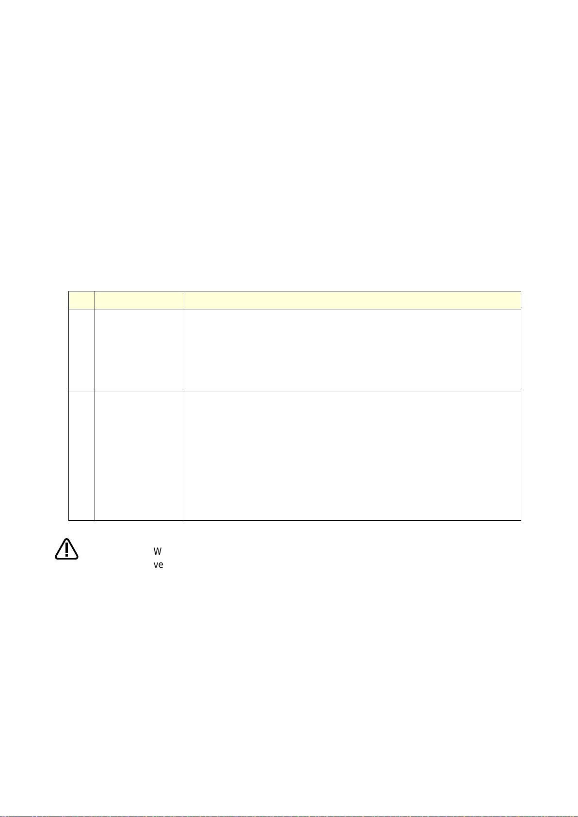
Page 11

Chapter
Title
Description
1
Before starting use
Explains the structure of this manual, products compatible
with this function, related manuals, and
maintenance/inspection.
2
Basic specifications
Explains the specification of the preventive maintenance
function.
3
Startup and initial settings
Explains how to start the preventive maintenance function
and the initial setting method.
4
Basic screen structure
Each preventive maintenance function is explained using
examples of the RT ToolBox3 Preventive Maintenance
screens.
5
Total score
6
Consumption degree
calculation function
7
Operating information
8
Maintenance simulation
9
When consumption occurred
Explains actions to take when consumption is detected.
10
Maintenance
Explains pause of warning occurrence related to this
function and operation at the time of maintenance using
examples of the RT ToolBox3 Preventive Maintenance
screens.
11
Batch management of
maintenance information
Explains how to collectively manage maintenance
information of the entire production line with the host
system.
12
Robot (system) status
variables
Explains robot (system) status variables, parameters, and
dedicated input/output signals related to the preventive
maintenance function.
13
Parameter
14
Dedicated input/output signals
15
Troubleshooting
Explains error details related to the preventive
maintenance function and actions to take.
1. Before starting use
1.1 Contents of the instruction manual
This function can be used with the RT ToolBox3 Preventive Maintenance screen, parameters, status
variables, and dedicated input/output signals.
In this manual, the following structure is used to explain how the preventive maintenance function using
examples of the RT ToolBox3 Preventive Maintenance screens.
For functions and operation methods provided in the standard robot controller, refer to the "Instruction
Manual" supplied for the robot controller.
Before starting use 1
Page 12
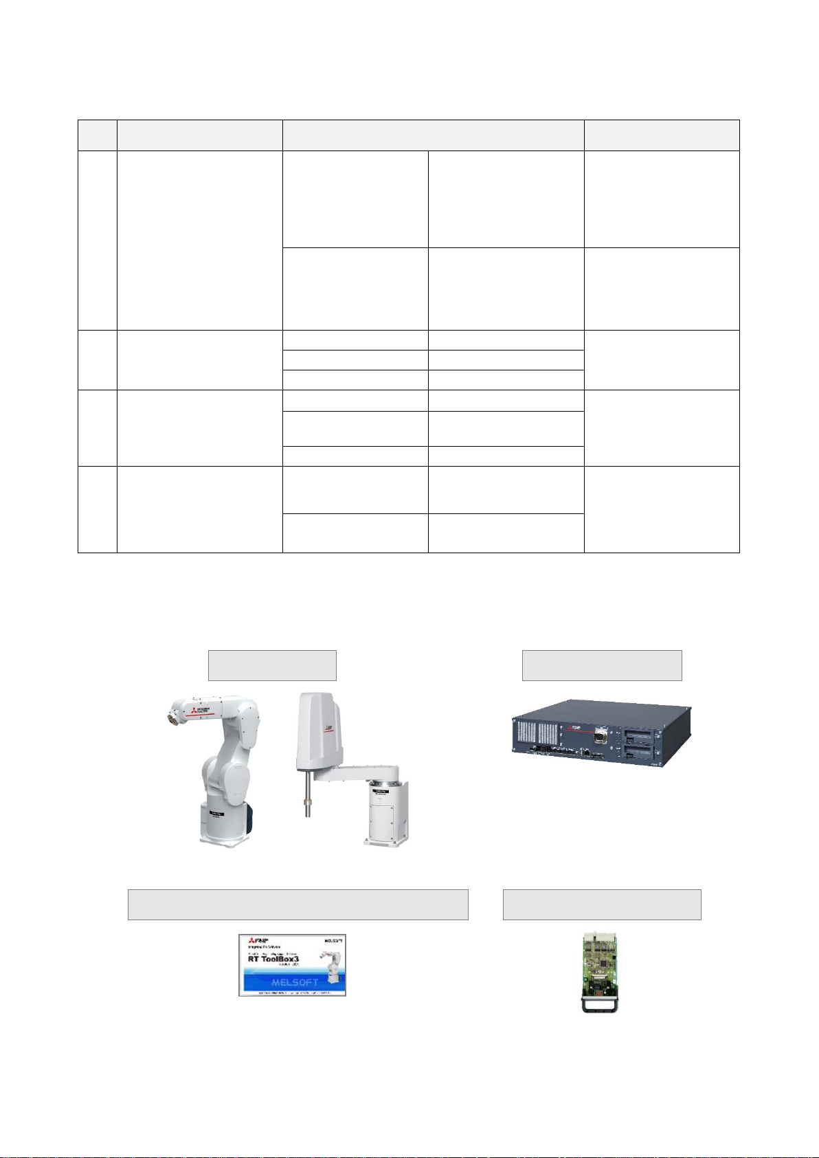
1.2 Compatible products
Item
Description
Remarks
1)
Robot arm
Vertical multi-joint
type RV-FR series
RV-2FR series,
RV-4FR series,
RV-7FR series,
RV-13FR series,
RV-20FR series
Standard model
6-axis robot only
Horizontal multi-joint
type RH-FR series
RH-3FRH series,
RH-6FRH series,
RH-12FRH series,
RH-20FRH series,
RH-3FRHR series
Standard model only
2)
Robot controller
CR800-D
Ver.A3 or later
CR800-R
Ver.A3 or later
CR800-Q
Ver.A3 or later
3)
Robot total engineering
support software
(Note 1)
RT ToolBox3
Ver.1.30G or later
Robot program
language:
MELFA-BASIC VI
RT ToolBox3 mini
(Note 2)
Ver.1.30G or later
RT ToolBox3 Pro
Ver.1.30G or later
4)
Function expansion card
MELFA Smart Plus
Card Pack
(Note 3)
A type (2F-DQ510)
AB type (2F-DQ520)
Either one
MELFA Smart Plus
Card
(Note 3)
A type (2F-DQ511)
Vertical multi-joint type
Horizontal multi-joint type
2) Robot controller
CR800 series
3) Robot total engineering support software
4) Function expansion card
1) Robot arm
RT ToolBox3
The following products are compatible with this function.
Note 1) Must be purchased separately.
Note 2) When RT ToolBox3 mini is used, simulation on RT ToolBox3 cannot be used.
Note 3) In this instruction manual, "MELFA Smart Plus card" may be used as the general term for MELFA
Smart Plus card pack and MELFA Smart Plus card.
Before starting use 2
Page 13

Manual name
Description
Robot Arm Setup & Maintenance
Explains the procedures required to operate the robot arm
(unpacking, transportation, installation, confirmation of operation),
and the maintenance and inspection procedures.
Detailed explanations of functions
and operations
Explains details on the functions and operations such as each
function and operation, commands used in the program,
connection with the external input/output device, and parameters,
etc.
CR800 Series Controller Instruction
Manual
Troubleshooting
Explains the causes and remedies to be taken when an error
occurs. Explanations are given for each error No.
RT ToolBox3 / RT ToolBox3 mini
User's Manual
The operation manuals for the robot total engineering support
software "RT ToolBox3", "RT ToolBox3 mini", "RT ToolBox3 Pro"
(Option).
MELFA Smart Plus User’s Manual
Describes the installation method and setting method of MELFA
Smart Plus card (Option).
Communication Middleware Manual
(MelfaRXM.ocx)
The operation manual for ActiveX controller "MelfaRXM.ocx" that
communicates with the robot controller.
Ethernet Function Instruction
Manual
The operation manual for the Ethernet function that enables
Ethernet communication with PCs using the TCP/IP protocol.
Also, explains the SLMP connection.
1.3 Related manuals
The following manuals are related to the preventive maintenance function.
Before starting use 3
Page 14

1.4 Maintaining the robot
No.
Type of inspection and
maintenance works
Description
Operating
time
(Note1)
1
Daily inspection
Inspection works to be performed every day
before starting operation for the safe use of the
robot.
2
Periodic
inspection
Monthly
inspection
Inspection and maintenance works to be
performed every month.
Every 300 hr
3
6-month
inspection
Inspection and maintenance works to be
performed every 6 months.
Every 1,800 hr
4
2-year
inspection
Inspection and maintenance works to be
performed every 2 years.
Every 7,200 hr
5
Battery
replacement
Replacement of the backup battery of the robot.
Replace the battery every year regardless of
the operating hours.
6
Lubrication
Lubrication of each axis of the robot.
Refer to "1.4.3 Lubrication" for the lubrication
schedule.
This function supports maintenance and inspection so that the robot can be used for a long time without
trouble.
Efficient maintenance is supported though notification of the time of maintenance parts replacement or
overhaul based on the actual operating status of the robot. However, in order to prevent failure
beforehand and ensure prolonged service life and safety of the robot, we strongly recommend periodic
maintenance and inspection be carried out.
This chapter explains maintenance and inspection of parts that are subject to this function.
For details on robot inspection items, implementation time of periodic inspection, calculation of operating
time, and maintenance and inspection procedures, refer to "5. Maintenance and Inspection" in the
separate volume "Instruction Manual/Robot Arm Setup & Maintenance".
1.4.1 Type of maintenance and inspection
There are two types of maintenance and inspection, daily inspection and periodic inspection.
The following table shows the type of maintenance and inspection.
Type of maintenance and inspection
Note 1) Robot operating hours are based on 15 hours/day, 20 days/month. If the robot operates 8
hours/day, the operation hours per month are about half the above condition. Therefore,
monthly inspection shall be performed once every two months.
Before starting use 4
Page 15
The timing belt can be replaced by customers; however, if adjustment is not
appropriate, it could lead to failure of related parts. When the timing belt needs to be
replaced, we recommend that you contact our Mitsubishi Service Department to
request replacement.
If you need to remove the timing belt for repair and others, measure the tension
before removing the belt.
When installing the belt, make sure to install with the same degree of tension as
before removal.
Failure to do so could shorten the service life of the belt and related parts.
Caution
Caution
1.4.2 Inspecting/replacing timing belt
This robot uses a timing belt for the drive conveyance system.
Compared to gears and chains, the timing belt does not require lubrication and has a low noise. However,
if the belt usage method and tension adjustment are inadequate, the life could drop and noise could be
generated. depending on the robot working conditions, elongation will occur gradually over a long time.
The tension must be confirmed during the periodic inspection.
The inspection/replacement method of the timing belt differs depending on the model. Perform
inspection/replacement by referring to "5. Maintenance and Inspection" in the separate volume
"Instruction Manual/Robot Arm Setup & Maintenance".
Timing belt replacement period
The timing belt life is greatly affected by the robot working conditions, so a set time cannot be given.
However, if the following symptoms occur, replace the belt.
1) The belt tension value becomes less than the guideline value.
2) Position mismatch or gear teeth skipping occurs.
3) Cracks or wear occurs on the belt.
4) The tooth bottom of the belt is worn out and the core is exposed.
Before starting use 5
Page 16
1.4.3 Lubrication
Robot type
Lubrication interval
RV-2FR / RV-2FRL
All axes: 6,000 hr
RV-4FR / RV-4FRL
RV-7FR / RV-7FRL
All axes: 24,000 hr
RV-7FRLL
RV-13FR / RV-13FRL
RV-20FR
J1 axis to J3 axis: 20,000 hr
J4 axis to J6 axis: 24,000 hr
RH-3FRH series
RH-6FRH series
RH-12FRH series
RH-20FRH series
J1 axis to J2 axis: 24,000 hr
Shaft part (ball screw / spline): 2,000 km/travel
RH-3FRHR series
J1 axis to J2 axis: 6,000 hr
Shaft part: 2,000 km/travel
• The lubrication intervals are the cumulative value of operation at maximum speed. In
case of intermittent operation or slow specified speed, the lubrication interval can be
• Since the lubrication interval changes depending on the operation status of the
• Avoid excessive lubrication as it could cause grease leakage. Also, lubrication shall
Caution
Grease is used for the reduction gears of the robot. Grease has various roles, such as suppressing of
wear of reduction gears, removal of frictional heat, and prevention of burn-in.
If you use a robot for a long period of time, the grease will deteriorate due to loads during operation
(operating speed, operation frequency, heat generation condition, and others.). Degraded grease loses
initial performance and adversely affects machine service life.
Therefore, periodic replacement of grease is essential.
Lubrication intervals, lubrication locations, lubrication specifications and lubrication methods for grease
are different for each model.
Lubricate the robot before the lubrication interval shown in the following table elapses.
In addition, before the servo ON time reaches the specified hours (24,000 hours), overhaul work to
replace the grease inside the robot is necessary.
If it is unavoidable that overhaul cannot be performed at the specified interval, lubricate at the lubrication
intervals shown in the following table.
For details on overhaul, refer to "1.4.5 About Overhaul".
Refer to "5. Maintenance and Inspection" in the separate volume "Instruction manual/Robot Arm Setup &
Maintenance" for lubrication locations, lubrication specifications, and lubrication methods.
Lubrication interval
extended accordingly.
robot, make decisions as necessary so that grease will not run out.
be performed a maximum of three times. For maintenance after that, overhaul work
is required to replace the grease inside.
Before starting use 6
Page 17

1.4.4 Replacing the battery
An absolute encoder is used for the position detector, so while power of controller is turned off the
position must be saved by the backup battery. These batteries are installed when the robot is shipped
from the factory, but as these are consumable parts, they must be replaced periodically by the customer.
The guideline for replacing the battery is one year, but this will differ according to the robot's usage state.
When a battery-related error occurred, replace the battery of the robot arm.
The robot arm battery replacement method differs depending on the model. Refer to "5. Maintenance and
Inspection" in the separate volume "Instruction Manual/Robot Arm Setup & Maintenance".
Before starting use 7
Page 18
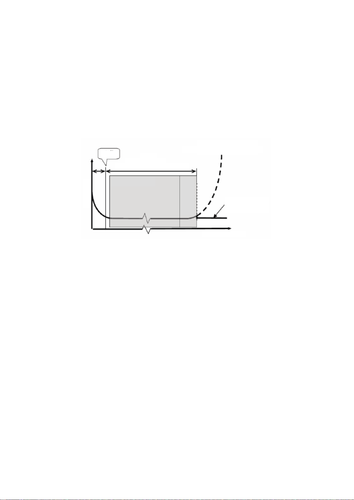
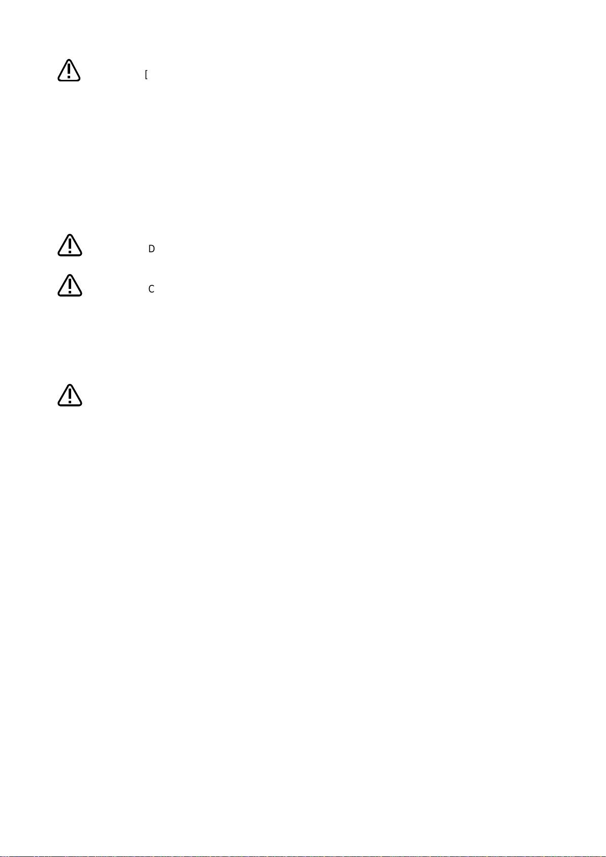
1.4.5 About Overhaul
Predetermined time period
If overhaul is not performed
If overhaul is performed
Servo-on time
Failure rate
λ
Periodic inspection
Overhaul
Shipment
Robots which have been in operation for an extended period of time can suffer from wear and other forms
of deterioration. In regard to such robots, we define overhaul as an operation to replace parts running out
of specified service life or other parts which have been damaged, so that the robots may be put back in
shape for continued use.
As a rule of thumb, it is recommended that overhaul be carried out before the total amount of servo-on
time reaches the specified time (24,000 hours for the robot arm and 36,000 hours for the controller).
(Refer to the figure below.)
However, the degree of the equipment's wear and deterioration presumably varies depending on their
operating conditions. Especially for operation with high load and frequency, the maintenance cycle may
be shorter.
Before starting use 8
Page 19
Function
Overview
1
Maintenance
simulation
Using the real machine or simulations on RT ToolBox3, this function
estimates the parts replacement time or the recommended maintenance
time when specific motion patterns are repeated.
This can be used for pre-study of maintenance cycles or parts-friendly
operation verification of robots.
(Refer to "8 Maintenance simulation".)
2
Consumption
degree calculation
function
This function calculates the consumption degree [%] of robot components
based on the actual operating status (motor speed, load status, and
others), and displays/notifies the period up to maintenance/inspection or
overhaul.
This supports efficient maintenance through notification of maintenance
timing and deciding the maintenance priority order.
<Target parts>
Maintenance parts : Grease, timing belt
Overhaul parts : Reduction gear, bearing, ball screw, ball spline
(Refer to "6 Consumption degree calculation function ".)
The consumption degree of the robot arm is saved in the robot controller, thus it is
necessary to use the correct combination of the robot arm and robot controller.
To replace the robot arm or robot controller only, perform backup/restore of
preventive maintenance information to migrate the preventive maintenance
information.
(For backup/restore, refer to "
When using this function by upgrading from a non-compatible controller software
version to a compatible controller software version, the consumption degree during
the period of the non-compatible software version is not added up, thus the result of
consumption degree calculation function cannot be the correct value.
Caution
2. Basic specifications
2.1 Overview of basic specification of the preventive maintenance function
The preventive maintenance function roughly consists of the following two functions.
The maintenance simulation can be checked on the preventive maintenance function screen of
RT ToolBox3.
Information on preventive maintenance by the consumption degree calculation function can be checked
on the Preventive Maintenance screen, status variables, and parameters of RT ToolBox3. The following
features are also available.
• Allows preventive maintenance information to be output to the host system of your production line and
collectively managed.
(Compatible with MelfaRXM.ocx and SLMP)
• If you are using a CR800 series Ver.A3 or later robot controller, by enabling this function using the
MELFA Smart Plus card, this function can be used by taking over the previous consumption degree
even during operation of the robot. (For compatible cards, refer to "1.2 Compatible products , 4) Function
extension card".)
10.3 Backup and restore".)
Basic specifications 9
Page 20

2.1.1 Maintenance simulation
Output data
Number of years up to the time of replenishing grease (for each joint axis)
Number of years up to the time of timing belt replacement (for each joint axis)
Number of years up to the recommended maintenance time for overhaul parts (for each joint axis)
(Of reduction gear, bearing, ball screw, and ball spline, the part for which there is the shortest number of years of
maintenance)
Estimation method
Real machine (online)
· Program operation
· Estimates the number of years from the current consumption degree of the
robot.
Simulation
· 1 Cycle operation, Program operation
· Estimates the number of years from the brand new robot state.
Usage
Usage
RT ToolBox3 Preventive Maintenance screen (Refer to 8.Maintenance simulation)
Setting item
· Operation hours per day, operation days per month
Using the real machine (online) or simulations on RT ToolBox3, this function estimates the parts
replacement time or the recommended maintenance time when specific motion patterns (robot
programs) are repeated.
Maintenance simulation estimates the following items.
1) Number of years up to the time of replenishing grease
2) Number of years up to the time of timing belt replacement
3) Recommended number of years up to the maintenance time for overhauling parts
(Of reduction gear, bearing, ball screw, and ball spline, the part for which there is the shortest
number of years of maintenance)
There are two types of estimation methods, "Program operation" and "1 Cycle operation".
For the real machine (online), estimation is possible using "Program operation", and for simulation, in
addition to "Program operation", "1 Cycle operation" can also be used.
•1 Cycle operation: Specify the start line and end line of the robot program to estimate the parts
replacement/ the recommended maintenance time based on its 1 cycle operation
pattern.
Because 1 cycle can be accurately specified on a robot program, it is possible to
more accurately estimate the number of years when 1 cycle operation is repeated
than when using Program operation.
The estimation result of the number of years is from the brand new robot state.
• Program operation: While running a robot program automatically, the parts replacement/ the parts
replacement/ the recommended maintenance time is estimated based on the
operation pattern from when the start button is pressed to when the end button is
pressed.
Accurate 1 cycle (start line and end line) cannot be specified but Program
operation is used when it is difficult to specify 1 cycle on the program, such as
when the program uses external signals.
The estimation result for a real machine (online) is the number of years from the
current consumption degree of the robot.
The estimation result for simulation is the number of years from the brand new
robot state.
* For models and joint axes subject to this function, refer to "2.1.3 Target models/target axes".
Basic specifications 10
Page 21

When RT ToolBox3 mini is used, simulation on RT ToolBox3 cannot be used.
The recommended number of years up to the replacement/maintenance time output
by this function is the value calculated when the specified operation is repeated.
Also, the result may vary depending on the performance of the personal computer
used and the load status. The actual time changes depending on the actual
operating status or load status of the robot.
Use as reference values for planning of maintenance and inspection.
Correctly set hand work conditions (weight, center of gravity, shape) actually used. If
the settings differ from the actual robot settings, the consumption degree cannot be
calculated correctly.
Use parameters HNDDAT* and WRKDAT* to set hand work conditions and use
Loadset commands to specify hand work conditions.
For details of hand work condition setting, refer to the separate "Instruction
Manual/Detailed Explanations of Functions and Operations".
Do not use M_TIMER(8) while programming. This function uses M_TIMER(8) for the
estimation of parts replacement time and maintenance time. If M_TIMER(8) is used
while programming, the number of years of replacement and maintenance cannot be
estimated accurately.
After changing to M_TIMER(1) to M_TIMER(7), perform the maintenance simulation.
Caution
Note on 1 Cycle operation
(1) For command line that waits for signals to be input or robot status changes, use a comment to
set the stop time.
For a program waiting for input of signal from outside or change of the robot status variable, comment
out that portion and instead set a stop time (assumed) and specify the start line and end line including
that line.
(2) Use a program with no infinite loop.
A program that executes an infinite loop does not give the correct calculation result.
Check that the program is not an infinite loop in a FOR or GOTO statement.
(3) Include all instructions required for 1 cycle in the line selection range.
When selecting the start line and end line of a program, specify line numbers in such a way that all
instructions such as jump destinations of Gosub or hand word settings required for the robot to
perform 1 cycle operation are included in the range.
When sending/receiving external signals, set the stop time as a substitute for the signal
sending/receiving time and specify the line numbers including that line.
(4) About robot program "ESTPROG.prg"
When executing 1 cycle operation, "ESTPROG" is displayed as the robot program on the operating
panel.
This is a program that is automatically generated when 1 cycle operation is executed. After 1 cycle
operation, you can delete this program if it is unnecessary.
Basic specifications 11
Page 22

2.1.2 Consumption degree calculation function
Target parts
Output data
Maintenance parts
Grease
Timing belt
Grease consumption degree [%] (for each joint axis)
Timing Belt consumption degree [%] (for each joint axis)
Total Score (Consumption Degree [%], Up to Maintenance
[h])*1
Overhaul parts
Reduction gear
Bearing
Ball screw/ball spline
Gear consumption degree [%] (for each joint axis)
Bearing consumption degree [%] (for each joint axis)
Ball Screw/Ball Spline consumption degree [%] (for each joint
axis)
Total Score (Consumption Degree [%])*2
Operating Information
-
Servo ON Time [h], Operation Time [h], Actual Operation
Time [h], Power ON Time [h], Servo ON Count [times], Motor
Cumulative Rotation Count [rotation] (for each joint axis)
Information confirmation
Information
· Consumption Degree: See above
· Up to Maintenance: See above (Total Score Maintenance Parts)
· Operating Information: See above
· [Consumption Status]: Existence of wear in each target part
· Maintenance Log: Log data under Maintenance Reset (date & time, parts, joint
axes)
Check method
RT ToolBox3 Preventive Maintenance screen (Refer to 5. Total score,
6 Consumption degree calculation function)
[Parameters] (Refer to 13.2.2 Data acquisition parameter.)
[Status Variable] (Refer to 12.2 Consumption degree calculation function)
Setting/operation
Setting item
· Notification Day setting: Warning Remaining Number of Days, Operation Time of
a Day, Notification Interval
· How to Notify setting (maintenance parts): Warning Occurrence, Signal Output
· How to Notify setting (overhaul parts): Warning Occurrence, Signal Output
· ["I/O Signals assignment"]
Setting method
RT ToolBox3 Preventive Maintenance screen (Refer to 3.2.1.Setting how to
notify)
[Parameters] (Refer to 13.2.1 Setting parameters.)
Operation item
· Maintenance Reset (reset of consumption degree)
· [Notification Pause]
Operation method
RT ToolBox3 Preventive Maintenance screen
(Refer to 10.1 Warning Pause, 10.2 Maintenance Reset)
[Parameters] (Refer to 13.2.3 Operation parameters.)
[I/O Signal]*1(Refer to 14 Dedicated input/output signals.)
This function calculates the consumption degree [%] of robot components based on the actual operating
status (motor speed, load status, and others), and calculates the period up to maintenance/inspection or
overhaul.
Consumption Degree [%] is calculated based on the recommended maintenance time of each part as 100
[%].
Beside consumption degree [%] of each robot component, the Total Score (Consumption Degree [%] and
Up to Maintenance) of maintenance parts (grease, timing belt), and the Total Score (Consumption
Degree [%]) of overhaul parts (reduction gear, bearing, ball screw, ball spline) are calculated, respectively
and are displayed on the comprehensive evaluation screen.
*1: Of the maintenance parts (grease, timing belt), the Consumption Degree [%] and Up to Maintenance
[h] of the part (joint axis) having the least remaining time are used.
*2: Of the overhaul parts (reduction gear, bearing, ball screw, ball spline), the Consumption Degree [%] of
the part (joint axis) having the least up to maintenance time is used.
Basic specifications 12
Page 23

Notification
Notification content
· [Consumption Status] (maintenance parts): Output for each part, for each joint
axis
· [Consumption Status] (overhaul parts): Output for each part, for each joint axis
· Servo ON Time*2
Notification method
RT ToolBox3 Preventive Maintenance screen
*3
(3.2.1.Setting how to notify)
Warning Occurrence
*1
(Refer to 3.2.1.Setting how to notify)
Signal Output
*1
(Refer to 3.2.2 Setting signals.)
Caution
[About calculation of the consumption degree]
• The consumption degree of each part is calculated on the assumption that the robot
• The consumption degree of each part is used as a reference value for supporting the
maintenance and inspection schedule calculated based on the robot operating status.
• Irrespective of the consumption degree, carry out daily inspection and periodic
• When the servo ON time exceeds the specified time (24,000 hours) or the
consumption degree exceeds the warning remaining number of days, we recommend
• Reset operation of the consumption degree of each part must not be executed except
• For the total score of maintenance parts and overhaul parts, the value of the part
• The remaining time is a reference value calculated based on the operating status of
*1 Setting is required.
*2 Notification of overhaul intervals by servo ON time follows "How to notify the consumption degree of
overhaul parts".
*3 A maintenance message is displayed.
* For models and joint axes subject to this function, refer to "2.1.3 Target models/target axes".
is used in the environment (ambient temperature, humidity) within the specification
scope described in the instruction manual (standard specifications).
It does not guarantee the service life of the robot.
maintenance and inspection described in the instruction manual (Standard
Specifications Manual, Robot Arm Setup & Maintenance).
you perform overhaul of the robot arm.
during maintenance or part replacement.
among all joint axes having the least remaining time (Up to Maintenance) to the
recommended maintenance time is output, respectively. For that reason, the
consumption degree of the total score could be smaller than the maximum
consumption degree value of each part.
the robot from the previous maintenance time. Also, the remaining time is when you
use the robot in the same way as before.
Therefore, if operation is changed, the remaining time may increase or decrease.
Basic specifications 13
Page 24
Correctly set hand work conditions (weight, center of gravity, shape) actually used.
If the settings differ from the actual robot settings, the consumption degree cannot
be calculated correctly.
Use parameters HNDDAT* and WRKDAT* to set hand work conditions and use
Loadset commands to specify hand work conditions.
For details of hand work condition setting, refer to the separate "Instruction
Manual/Detailed Explanations of Functions and Operations".
Depending on the operating status at startup, correct results may not be obtained
at the beginning due to fluctuations until sufficient data is accumulated.
When the preventive maintenance function is valid, the maintenance forecast is not
displayed and warning signals of maintenance forecast are not output.
information is reset by the preventive maintenance function or maintenance
forecast, the information in the other function is reset as well.
[About the robot controller]
• When using this function by upgrading from a non-compatible controller software
version to a compatible controller software version, the consumption degree during
the period of the non-compatible software version is not added up, thus the result of
• The consumption degree of the robot arm is saved in the robot controller, thus it is
Caution
Caution
Caution
Caution
consumption degree calculation function cannot be the correct value.
necessary to use the correct combination of the robot arm and robot controller.
To replace the robot arm or robot controller only, perform backup/restore of
preventive maintenance information to migrate the preventive maintenance
information.
(For backup/restore, refer to "10.3 Backup and restore".)
When the
Basic specifications 14
Page 25

<< MEMO >>
Basic specifications 15
Page 26
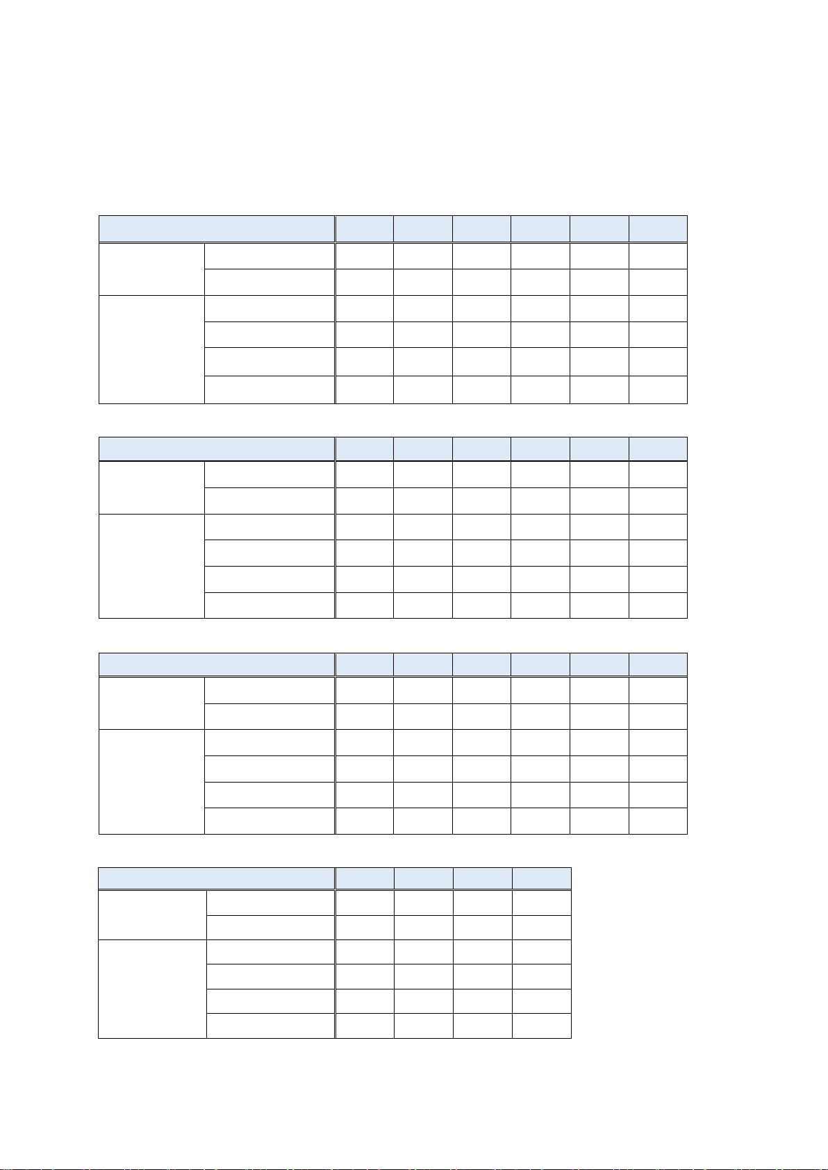
2.1.3 Target models/target axes
Joint axis
J1 axis
J2 axis
J3 axis
J4 axis
J5 axis
J6 axis
Maintenance
parts
Grease
Timing belt
Overhaul parts
Reduction gear
Bearing
Ball screw
- - - - -
-
Ball spline
- - - - -
-
Joint axis
J1 axis
J2 axis
J3 axis
J4 axis
J5 axis
J6 axis
Maintenance
parts
Grease
Timing belt
-
Overhaul parts
Reduction gear
Bearing
-
Ball screw
- - - - -
-
Ball spline
- - - - -
-
Joint axis
J1 axis
J2 axis
J3 axis
J4 axis
J5 axis
J6 axis
Maintenance
parts
Grease
Timing belt
- - -
Overhaul parts
Reduction gear
Bearing
- - -
Ball screw
- - - - -
-
Ball spline
- - - - -
-
Joint axis
J1 axis
J2 axis
J3 axis
J4 axis
Maintenance
parts
Grease
-
Timing belt
-
-
Overhaul parts
Reduction gear
-
-
Bearing
-
-
*1
Ball screw
-
-
*2
-
Ball spline
- - -
2
(1) Consumption degree calculation function/maintenance simulation
The table below shows the joint axes for which target parts of the consumption degree calculation
function of each robot type are used.
(Compatible robots are the standard models only.)
(: Uses target parts, -: Not use target parts)
(1) RV-2FR / RV-2FRL
(2) RV-4FR / RV-4FRL / RV-7FR / RV-7FRL
Basic specifications 16
(3) RV-13FR / RV-13FRL / RV-20FR / RV-7FRLL
(4) RH-3FRH / RH-6FRH / RH-12FRH / RH-20FRH
*1: For RH-3FRH, J3 axis does not use a bearing, shown as (-).
*2: RH-3FRH uses a ball screw/spline but this function assumes that the J3 axis uses a ball screw and
the J4 axis uses a ball spline.
Page 27

Joint axis
J1axis
J2 axis
J3 axis
J4 axis
Maintenance
parts
Grease
-
Timing belt
Overhaul parts
Reduction gear
-
-
Bearing
-
Ball screw
-
-
*3
-
Ball spline
- - -
*3
(5) RH-3FRHR
*3:The RH-3FRHR series uses a ball screw/spline but this function assumes that the J3 axis uses a ball screw and
the J4 axis uses a ball spline.
Basic specifications 17
Page 28

2.2 How to utilize the preventive maintenance function
The preventive maintenance function assumes the following usages.
(1) At system startup
It is possible to estimate the replacement time of maintenance parts or the recommended maintenance
time of overhaul parts when an operation pattern of the robot is repeated using "Maintenance Simulation".
This function can be used for planning a maintenance schedule when starting up a system.
(For details, refer to "8 Maintenance simulation".)
(2) System operation time (at periodic inspection)
You can check the consumption degree using the "Consumption degree calculation function".
Because the consumption degree calculation function calculates the consumption degree based on the
actual robot operation status (motor speed, loads, and others), you can check the current robot
consumption degree and remaining time to replacement/maintenance.
This function is useful for reviewing or planning a maintenance schedule.
(For function details, refer to "6 Consumption degree calculation function".)
(3) System operation time (when a part is consumed)
As a result of the remaining time to replacement/maintenance calculated by the consumption degree
calculation function, if the set remaining time is reached, that effect is notified by the method you set.
Check detailed information and arrange or carry out maintenance.
By carrying out appropriate maintenance, it is possible to prevent the production line from stopping due
to a sudden failure of the robot and reduce down time.
(For function details, refer to "6 Consumption degree calculation function".)
Basic specifications 18
Page 29

<< MEMO >>
Basic specifications 19
Page 30
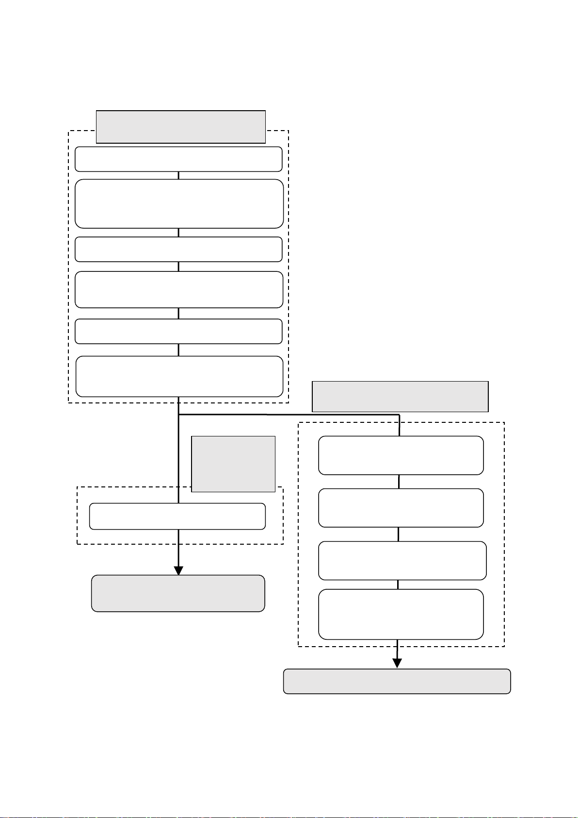
3. Startup and initial settings
7. Set the notification method.
Now you can use the preventive
4. Start the preventive
simulation mode.
1. Get the function code of the
"MELFA Smart Plus Card".
4. Set the MELFA Smart Plus enable
parameter.
3. Turn on the power of the robot controller.
2. Insert the "MELFA Smart Plus Card" or
controller.
1. Turn off the power of the robot controller.
2. Enter the function code of the
"MELFA Smart Plus Card".
5. Restart the robot controller.
3. Set the MELFA Smart Plus
enable parameter.
Initial setting of
function (3.2)
enance function (3.1)
Maintenance simulation can be used.
Setting of maintenance simulation
(3.3)
6. Check if the preventive maintenance
function is in enable state.
• Consumption degree calculation
Maintenance simulation
(RT ToolBox3 simulation)
This section describes the procedure to start the preventive maintenance function.
Validation of the preventive maint
"MELFA Smart Plus Card Pack" into the
the preventive
maintenance
• Maintenance simulation (real
machine (online))
maintenance function in
Startup and initial settings 20
Page 31

Turn off the power of the robot controller.
Switch
Earth leakage circuit breaker
1) Turn off the switch of the earth leakage
circuit breaker.
1) Turns off the power of the robot CPU system.
breaker.
1
CR800-D type
CR800-R/Q type
Insert the MELFA Smart Plus card into the robot controller.
Insert the "MELFA Smart Plus Card" or the "MELFA Smart Plus Card Pack" in an available
2
Robot controller
CR800 series
SLOT1
SLOT2
Interface cover
Interface cover
Connection connector
Removal lever
(lower side)
LED
Handle
(Note)
"1.2 Compatible products 4) Function
expansion card".
Install only one MELFA Smart Plus card.
If multiple MELFA Smart Plus cards have been installed, the LED will not flash and an
error (L3782) will occur. For error details, refer to "
".
Caution
3.1 Enabling the preventive maintenance function
Insert the "MELFA Smart Plus Card" into the robot controller and set parameters.
2) Turn off the switch of the earth leakage circuit
slot on the robot controller. (Note: For compatible cards, refer to "1.2 Compatible products C
ompatible products, 4) Function extension card".)
1) Lightly hold the interface cover removal lever to pull out the interface cover.
2) Hold the handle of the MELFA Smart Plus card and insert it into SLOT1 or SLOT2.
At that time, insert in such a way that both ends of the card fit into the groove of the slot (SLOT1
or SLOT2 in the illustration).
3) Insert the connection connector all the way to the end until the removal lever clicks into place to
be locked.
Removal lever
MELFA Smart Plus card or
MELFA Smart Plus card
pack (Note)
For compatible cards, refer to
15.1.3. MELFA Smart Plus card
Startup and initial settings 21
Page 32

Earth leakage circuit breaker
Turn on the power of the robot controller.
Switch
1) Turn on the switch of the earth leakage circuit
breaker.
2) The POWER lamp of the robot controller lights.
1) Turn on the switch of the earth leakage circuit
3) Next, turn on the power of the robot CPU system.
3
CR800-D type
CR800-R/Q type
* When the robot controller starts up, the LED of the MELFA Smart Plus card flashes.
Selecting the MELFA Smart Plus function and setting the preventive
maintenance function enable parameters.
4
With a robot controller where the "MELFA Smart Plus Card" has been inserted, set the MELFA
breaker.
2) The POWER lamp of the robot controller lights.
• MELFA Smart Plus Card ... Flashes in red.
• MELFA Smart Plus Card Pack ... Flashes in blue.
Smart Plus function selection parameter "SMART+1" and the preventive maintenance function
enable parameter "PMENA".
For this operation, use the teaching pendant or RT ToolBox3.
* Be aware that parameters to be set are different between the "MELFA Smart Plus Card" and
"MELFA Smart Plus Card Pack". For parameters, refer to "13. Parameter".
[When using the MELFA Smart Plus card]
1) Change the parameter "SMART+1" value to [4].
2) Change the parameter "PMENA" value to [1].
[When using the MELFA Smart Plus card pack]
1) Change the parameter "PMENA" value to [1].
Startup and initial settings 22
Page 33

Restart the robot controller.
5
1) Turn off the switch of the earth leakage circuit breaker.
2) Turn on the switch of the earth leakage circuit breaker.
1) Turns off the power of the robot CPU system.
CR800-D type
CR800-R/Q type
Check that the preventive maintenance function is enabled.
6
1) When the MELFA Smart Plus card is used, the LED of the MELFA Smart Plus card flashes
RT ToolBox3
project tree
Preventive Maintenance
Maintenance
2) Turn off the switch of the earth leakage circuit breaker.
3) Turn on the switch of the earth leakage circuit breaker.
4) After the POWER lamp of the robot controller lights, turn on the power of the robot
CPU system.
green.
When the MELFA Smart Plus card pack is used, the LED flashes blue.
2) Check that the preventive maintenance function has been enabled.
• For the teaching pendant
Check that the "MSPPMENA" parameter is set to [1].
• For RT ToolBox3
Connect RT ToolBox3 to the robot controller and start a project from "Online"
Click [Online] - [Maintenance] to expand the project tree and check that "Preventive
Maintenance" is displayed.
Startup and initial settings 23
Page 34

3.2 Initial setting of the preventive maintenance function
Set the notification method.
7
[Setting] - [Synthesis] screen
1) From the RT ToolBox3 project tree, double-click [Online] - [Maintenance] - [Preventive
the [Setting] - [Synthesis] screen appears.
4) Writing
1) Consumption
calculation
2) Notification day
3) Notification
interval
Set how to notify when consumption of parts is detected.
Specify the notification method (presence of warning/signal output, notification day) when the warnings
occurr.
If you have not set the notification method, upon starting the preventive maintenance function, the
[Setting] - [Synthesis] screen appears.
[Note] In the default setting, notification is disabled. Make sure to set according to your environment.
3.2.1 Setting how to notify
Maintenance].
2) From the preventive maintenance tree, click [Setting] - [Synthesis].
* If you have not set the notification method, upon clicking [Preventive Maintenance],
degree
Preventive maintenance becomes available after setting the notification method.
1) Consumption degree notification method:
Set how to notify consumption of maintenance parts and overhaul parts. You can select Warning
Occurrence or Signal Output, or both.
Warning Occurrence ... A warning occurs and the error number and error message are displayed
according to the situation.
Signal Output ... The status can be checked with dedicated output signals.
(Setting of signal numbers are required. Refer to "3.2.2 Setting signals ".)
2) Consumption degree notification day:
Warning Remaining Number of Days: Set the number of remaining days for warning to occur.
Operation Time of a Day: Set the number of hours of operation of the robot per day.
3) Consumption degree notification interval: Set the interval of notification of warning.
4) Write: Writes setting items on the robot controller.
Startup and initial settings 24
Page 35

1) From the RT ToolBox3 project tree, double-click [Online] - [Maintenance] - [Preventive
set in the parameters are 0 to 255, 2000 to 5071, 6000 to 8047, and 10000 to 18191.
Preventive Maintenance Signal screen
4) IODATA setting
4) IODATA setting screen
5) Writing
3.2.2 Setting signals
Set signal numbers when you wish to use signal input/output to implement notification when consumption
or parts is detected, reset the consumption degree, or pause warning occurrence/signal output.
For dedicated input/output signals of the preventive maintenance function, refer to "14 Dedicated
input/output signals".
Maintenance].
2) From the Preventive Maintenance tree, click [Setting] - [Signal].
3) Enter the signal number for the item to be set.
4) When setting an axis bit pattern for reset/pause, click "IODATA Setting". When IODATA Setting
screen appears, set necessary information and click "Write".
5) After changing the parameter values, click the Write button to write them to the robot controller.
Note 1) Set the signal numbers according to the system to be used. The range of values that can be
(Note 1)
Startup and initial settings 25
Page 36

3.3 Setting of maintenance simulation
Get the function code of the MELFA Smart Plus card.
1
1) Use the RT ToolBox3 connected to the robot controller where the MELFA Smart Plus card and
First, get the function code from the robot controller where the MELFA Smart Plus card and
function" is completed).
[When using the maintenance simulation on a personal computer connected to the real machine]
3) When you click the "Get function code" button, the function code of the "MELFA Smart Plus Card"
2) Parameter list
3) MSPCODE
Parameter List screen
4) Write down the function code in a memo.
In order to use "Maintenance Simulation" for the simulation of RT ToolBox3, the function code and
parameter of the MELFA Smart Plus card need to be set to RT ToolBox3.
This section explains the procedure for setting the function code of the MELFA Smart Plus card to RT
Toolbox3, which is not connected to the robot controller where the MELFA Smart Plus card has been
installed.
(For maintenance simulation, refer to "8. Maintenance simulation".)
preventive maintenance function have been enabled ("3.1 Enabling the preventive maintenance
preventive maintenance function have been enabled.
2) From the RT ToolBox3 project tree, select [Parameter List].
3) Enter "MSPCODE" for the parameter name on the Parameter List screen.
4) The function code (24 alphanumeric characters) of the "MELFA Smart Plus Card" is displayed;
write it down in a memo.
*It is possible to read the "MSPCODE" parameter with the teaching pendant.
1) Select [Option] from the [Workspace] tab of RT ToolBox3.
2) From the left tree on the Option screen, select MELFA Smart Plus.
is displayed in the "Function code" field. (See the screen on the next page.)
* Now you can use the maintenance simulation with a personal computer connected to the real
Startup and initial settings 26
machine.
Page 37

Set the function code of the MELFA Smart Plus card.
2
1) Start RT ToolBox3 that performs the maintenance simulation. At that time, click the right button of
Next, enter the function code obtained in Step 1 to the RT ToolBox3 that performs the maintenance
simulation.
2) Option
3) MELFA Smart Plus
Option screen
5) Setting
Set the preventive maintenance function enable parameter.
3
Set the parameter to enable preventive maintenance.
PMENA
Parameter List screen
Set the "PMENA"
the mouse on the desktop icon of RT ToolBox3 and select "Implement as administrator" from the
displayed menu.
2) Select [Option] from the [Workspace] tab of RT ToolBox3.
3) From the left tree on the Option screen, select MELFA Smart Plus.
4) Enter the MELFA Smart Plus card function code obtained in Step 1 to the "Function code" field.
5) Press the Set button.
6) Restart RT ToolBox3.
1) Open the workspace that performs the maintenance simulation. Open the project.
2) Open the parameter list of the project that performs the maintenance simulation.
3) Set the "PMENA" preventive maintenance function parameter to [1: Enable].
parameter for
each project.
Startup and initial settings 27
Page 38

Check that the preventive maintenance function is enabled.
4
1) Change the operation mode to <Simulation>.
If parameter setting in Step 3 is performed using <Simulation>, start up Simulation once again.
Preventive Maintenance
Maintenance
(The "PMENA" parameter requires rebooting.)
2) From the project tree, expand [Maintenance] and check that [Preventive Maintenance] is
displayed.
Startup and initial settings 28
Page 39

<< MEMO >>
Startup and initial settings 29
Page 40
4. Basic screen structure
RT ToolBox3 project tree
1) Preventive
Maintenance
(1) Total score
Preventive
Preventive maintenance function tree
[Preventive Maintenance] is displayed
under [Maintenance] of the project tree.
on the right side changes.
(2) Consumption degree calculation
Main screen
The "Total Score" screen is displayed first when starting the preventive maintenance function.
This screen displays the total evaluation result of the consumption degree calculation function.
maintenance
function tree
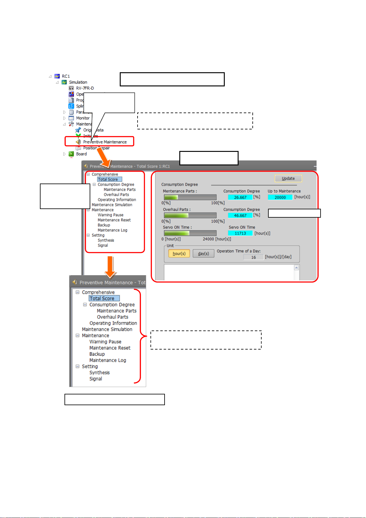
1) From the RT ToolBox3 project tree, when you double-click [Maintenance] - [Preventive Maintenance], the
preventive maintenance function starts and the Total Score screen appears.
2) In the Total Score screen, the preventive maintenance function tree is displayed on the left side and the main
screen on the right side.
3) When you click the + mark in the preventive maintenance function tree, menus of the preventive maintenance
function appear.
4) When you click an item on the preventive maintenance function tree, the main screen on the right changes.
Basic screen structure 30
When you click an item, the main screen
(3) Operating information
(4) Maintenance simulation
(5) Maintenance
(6) Setting
Page 41

(1) Total score
The screen that is displayed first when starting the preventive maintenance function.
This screen displays the total evaluation result of the consumption degree calculation function, and
maintenance messages.
For details, refer to "5 Total score".
(2) Consumption degree calculation
The screen indicates the consumption degree of each part and each joint axis of maintenance parts and
overhaul parts calculated by the consumption degree calculation function.
For details, refer to "6 Consumption degree calculation function".
(3) Operating information
The screen that displays the integration time and accumulation count from the time when the previous
overhaul was carried out.
• Integration Time [hours]: Power ON Time, Servo ON Time, Operation Time, Actual Operation Time
• Accumulation Count [times] : Servo ON Count, Motor Cumulative Rotation Count
For details, refer to "7 Operating information".
(4) Maintenance simulation
Using the real machine (online) or simulations on RT ToolBox3, this function estimates the parts
replacement time or the recommended maintenance time when specific motion patterns (robot programs)
are repeated.
For details, refer to "8 Maintenance simulation".
(5) Maintenance
This menu is used to specify pause of warning occurrence/signal output, and reset the consumption
degree of maintenance parts and overhaul parts, backup, restore, and checking of the maintenance log.
For details, refer to "10 Maintenance".
(6) Setting
This menu is used to set the preventive maintenance function including the presence of warning
occurrence, signal output and its occurrence intervals, and set dedicated input/output signals.
For details, refer to "3.2.1 Setting how to notifySetting how to notify".
Basic screen structure 31
Page 42

5. Total score
Classification
Target parts
Display description
Maintenance parts
Grease, timing belt
Consumption degree [%], remaining time up to the
recommended maintenance time
The remaining time of each joint axis of maintenance
parts is calculated and Consumption Degree [%] and
Up to Maintenance [h] of the part (joint axis) having the
least remaining time to the recommended maintenance
time is displayed.
Overhaul parts
Reduction gear, bearing, ball
screw/ball spline
Consumption degree [%]
The remaining time of each joint axis is individually
calculated and the consumption degree [%] of the part
(joint axis) having the least remaining time is used.
Total score
calculation
The "Total Score" screen is displayed first when starting the preventive maintenance function.
This screen displays the total evaluation result of the consumption degree calculation function.
(1) Consumption degree
(2) Preventive maintenance message
(1) Consumption degree calculation
The Consumption Degree area indicates the total score (Consumption Degree [%] and Up to
Maintenance) of maintenance parts (grease, timing belt), and the total score (Consumption Degree
[%]) of overhaul parts (reduction gear, bearing, ball screw, ball spline), and the accumulated servo ON
time since the previous overhaul time.
Consumption degree [%] is displayed based on the recommended maintenance time of each part as
100 [%].
You can check details of each part and joint axis on the Consumption Degree screen.
(Refer to "6 Consumption degree calculation function".)
Maintenance parts and overhaul parts
When the consumption status comes close to or exceeds the notification day you specified, check the
content of the preventive maintenance message displayed at the bottom of the screen and details of
each part/each joint axis on the Consumption Degree screen and take measures.
For preventive maintenance message and measures, refer to "9 When consumption occurred".
Total score 32
Page 43

(3) Preventive maintenance message
When the consumption status of the target part exceeds the notification day you specified, the
preventive maintenance message according to the status is displayed; check the message content and
take measures.
For preventive maintenance messages and measures, refer to "9 When consumption occurred".
Total score 33
Page 44
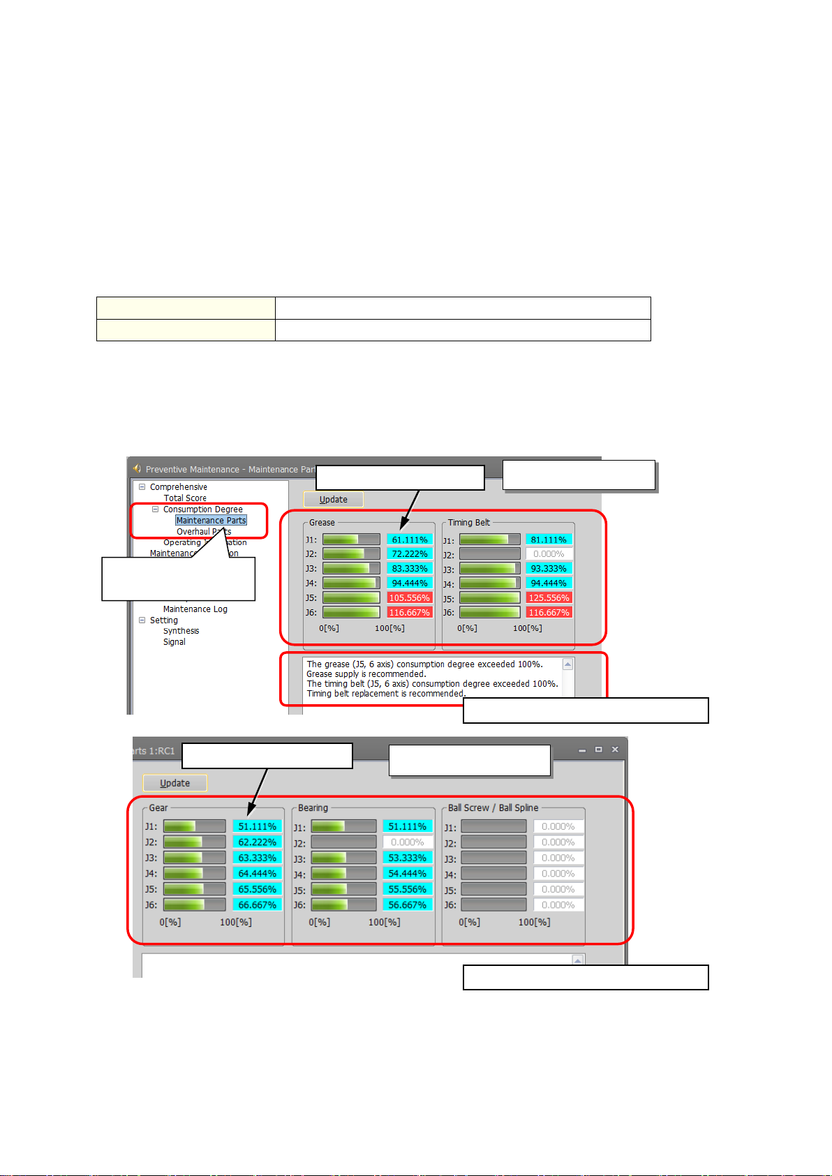
6. Consumption degree calculation function
Maintenance parts
Grease, timing belt
Overhaul parts
Reduction gear, bearing, ball screw/ball spline
1) Start preventive maintenance.
Consumption degree
calculation
(1) Consumption degree
(1) Consumption degree
(2) Preventive maintenance message
(2) Preventive maintenance message
This function calculates the consumption degree [%] of robot components based on the actual operating
status (motor speed, load status, and others), and calculates the period up to maintenance/inspection or
overhaul.
The screen indicates the consumption degree of each joint axis of maintenance parts and overhaul parts
calculated by the consumption degree calculation function.
The current status of maintenance parts (grease, timing belt) and overhaul parts (reduction gear, bearing,
ball screw/ball spline) is displayed, separately in two screens. Also, the current status is displayed as the
preventive maintenance message.
Maintenance parts and overhaul parts
2) Click [Total Score] - [Consumption Degree] to expend the menu.
3) When you select "Maintenance Parts" or "Overhaul Parts", the consumption degree of each part
of the target axis and each joint axis is displayed.
Overhaul parts
Maintenance parts
(1) Consumption degree
This area of the screen indicates the consumption degree of each part of the target axis and
each joint axis in a graph and numeric value [%].
Consumption degree calculation function 34
(For target axis, refer to "2.1.3 Target models/target axes".)
Page 45

[About calculation of the consumption degree]
• The consumption degree of each part is calculated on the assumption that the
specification scope described in the instruction manual (standard specifications).
• The consumption degree of each part is used as a reference value for supporting
• Irrespective of the consumption degree, carry out daily inspection and periodic
• When the servo ON time exceeds the specified time (24,000 hours) or the
• Reset operation of the consumption degree of each part must not be executed
• For the total score of maintenance parts and overhaul parts, the value of the part
• The remaining time is a reference value calculated based on the operating status
Therefore, if operation is changed, the remaining time may increase or decrease.
Caution
[About the robot controller]
• When using this function by upgrading from a non-compatible controller software
• The consumption degree of the robot arm is saved in the robot controller, thus it
(For backup/restore, refer to "10.3 Backup and restore".)
Caution
(2) Preventive maintenance message
This field displays preventive maintenance messages according to the part status.
When the remaining time exceeds the notification day, an appropriate preventive maintenance
message is displayed; check the message content and take measures. For preventive maintenance
message and measures, refer to "9.When consumption occurred".
robot is used in the environment (ambient temperature, humidity) within the
the maintenance and inspection schedule calculated based on the robot
operating status. It does not guarantee the service life of the robot.
maintenance and inspection described in the instruction manual (Standard
Specifications Manual, Robot Arm Setup & Maintenance).
consumption degree exceeds the warning remaining number of days, we
recommend you perform overhaul of the robot arm.
except during maintenance or part replacement.
among all joint axes having the least remaining time (Up to Maintenance) to the
recommended maintenance time is output, respectively. For that reason, the
consumption degree of the total score could be smaller than the maximum
consumption degree value of each part.
of the robot from the previous maintenance time. Also, the remaining time is
when you use the robot in the same way as before.
version to a compatible controller software version, the consumption degree
during the period of the non-compatible software version is not added up, thus
the result of consumption degree calculation function cannot be the correct
value
is necessary to use the correct combination of the robot arm and robot
controller.
To replace the robot arm or robot controller only, perform backup/restore of
preventive maintenance information to migrate the preventive maintenance
information.
Consumption degree calculation function 35
Page 46

Correctly set hand work conditions (weight, center of gravity, shape) actually used.
If the settings differ from the actual robot settings, the consumption degree cannot
be calculated correctly.
Use parameters HNDDAT* and WRKDAT* to set hand work conditions and use
Loadset commands to specify hand work conditions.
For details of hand work condition setting, refer to the separate "Instruction
Manual/Detailed Explanations of Functions and Operations".
Depending on the operating status at startup, correct results may not be obtained at
the beginning due to fluctuations until sufficient data is accumulated.
When the preventive maintenance function is valid, the maintenance forecast is not
displayed and warning signals of maintenance forecast are not output. When the
information is reset by the preventive maintenance function or maintenance
forecast, the information in the other function is reset as well.
Caution
Caution
Caution
Consumption degree calculation function 36
Page 47

Classification
Data
Unit
Integration
Time
Power ON Time (duration of robot controller power ON)
[h] hours
Servo ON Time (duration of servo ON)
[h] hours
Operation Time (duration of robot program execution)
[h] hours
Actual Operation Time (duration of actual robot arm operation)
[h] hours
Accumulation
Count
Servo ON Count (robot)
[times]
Motor Cumulative Rotation Count (for robot, each joint axis)
[r] (rotation)
1) Start preventive maintenance.
indicated on the main screen.
Operating information
7. Operating information
The Operating Information screen is used to manage and display the integration time and
accumulation count from the time when the previous overhaul was carried out.
The integration time and accumulation count data are reset when "Reset operation at overhaul
implementation" is performed.
2) Click [Total Score] to expand the menu.
3) When you select [Operating Information], the integration time and accumulation count are
■Data that can be monitored
Operating information 37
Page 48

8. Maintenance simulation
Operation mode
Estimation method
Number of years estimated
Real machine (online)
Program operation
The number of years from the current
consumption degree of the robot.
Simulation
1 Cycle operation, Program operation
The number of years from the brand
new robot state.
This function estimates the parts replacement time or the recommended maintenance time when a
specific motion pattern (robot program) is repeated using a real machine (online) or simulations on RT
ToolBox3.
Maintenance simulation estimates the following items.
1) Number of years up to the time of replenishing grease
2) Number of years up to the time of timing belt replacement
3) Recommended number of years up to the recommended maintenance time for overhauling parts
(Of reduction gear, bearing, ball screw, and ball spline, the part for which there is the shortest
number of years of maintenance)
There are two types of estimation methods, "Program operation" and "1 Cycle operation".
For the real machine (online), estimation is possible using "Program operation", and for simulation, in
addition to "Program operation", "1 Cycle operation" can also be used.
• 1 Cycle operation: Specify the start line and end line of the robot program to estimate the parts
replacement/ the recommended maintenance time based on its 1 cycle operation
pattern.
Because 1 cycle can be accurately specified on a robot program, it is possible to
more accurately estimate the number of years when 1 cycle operation is
repeated than when using Program operation.
The estimation result of the number of years is from the brand new robot state.
• Program operation: While running a robot program automatically, the parts replacement/the
recommended time is estimated based on the operation pattern from when the
start button is pressed to when the end button is pressed.
Accurate 1 cycle (start line and end line) cannot be specified but Program
operation is used when it is difficult to specify 1 cycle on the program, such as
when the program uses external signals.
The estimation result for a real machine (online) is the number of years from the
current consumption degree of the robot. The estimation result for simulation is
the number of years from the brand new robot state.
[Note] In order to use Maintenance Simulation in the simulation mode of RT ToolBox3, the function code and
parameter of the MELFA Smart Plus card need to be set.
For the setting method, refer to "3.3 Setting of maintenance simulation ".
Maintenance simulation 38
Page 49

When RT ToolBox3 mini is used, simulation on RT ToolBox3 cannot be used.
The recommended number of years up to the replacement/maintenance time output
by this function is the value calculated when the specified operation is repeated.
Also, the result may vary depending on the performance of the personal computer
used and the load status. The actual time changes depending on the actual
operating status or load status of the robot.
Use as reference values for planning of maintenance and inspection.
Correctly set hand work conditions (weight, center of gravity, shape) actually used.
If the settings differ from the actual robot settings, the consumption degree cannot
be calculated correctly.
Use parameters HNDDAT* and WRKDAT* to set hand work conditions and use
Loadset commands to specify hand work conditions. For details of hand work
condition setting, refer to the separate "Instruction Manual/Detailed Explanations of
Functions and Operations".
Caution
Do not use M_TIMER(8) while programming. This function uses M_TIMER(8) for
the estimation of parts replacement time and maintenance time. If M_TIMER(8) is
used while programming, the number of years of replacement and maintenance
cannot be estimated accurately.
After changing to M_TIMER(1) to M_TIMER(7), perform the maintenance
simulation.
Maintenance simulation 39
Page 50

8.1 "1 Cycle" operation
Select the following lines.
operation are included.
9 Dim PA(3)
If selected lines are set as:
occurs.
Example setting of line
selection range
49th line: Standby time for external signal
This operation is performed in the simulation mode of the RT ToolBox3.
Specify the start line and end line of the robot program to estimate the parts replacement/ the
recommended maintenance time based on its 1 Cycle operation pattern.
[Note] When an actual machine is connected, the "1 Cycle" button is not displayed.
Note on 1 Cycle operation
(1) For command line that waits for signals to be input or robot status changes, use a comment
to set the stop time.
For a program waiting for input of signal from outside or change of the robot status variable,
comment out that portion and instead set a stop time (assumed) and specify the start line and end
line including that line.
(2) Use a program with no infinite loop.
A program that executes an infinite loop does not give the correct calculation result.
Check that the program is not an infinite loop in a FOR or GOTO statement.
(3) Include all instructions required for 1 cycle in the line selection range.
When selecting the start line and end line of a program, specify line numbers in such a way that all
instructions such as jump destinations of Gosub or hand word settings required for the robot to
perform 1 cycle operation are included in the range.
When sending/receiving external signals, temporarily set the stop time as a substitute for the signal
sending/receiving time and specify the line numbers including that line.
Example) If there is no jumping destination of a sub routine within the selected range, an error
(jumping destination does not exist) occurs and the maintenance simulation cannot be executed.
Start line: 11
End line: 30
Since there is no jumping
destination of the location
array declaration Gosub
statement within the
selected range, an error
(4) About robot program "ESTPROG.prg"
When executing 1 cycle operation, "ESTPROG" is displayed as the robot program on the operating panel.
This is a program that is automatically generated when 1 cycle operation is executed. After 1 cycle
operation, you can delete this program if it is unnecessary.
10 Loadset 8,8
11 Mov PHOME
12 Mvs PA(1)
13 GoSub *SUB1
•
•
30 End
31 *SUB1
33 Mov P01
35 Mvs PA(2)
•
•
49 Dly 1.0
50 Return
Start line: 9
End line: 50
Set the start line and end line
so that all lines such as the
array declaration, the jumping
destination of Gosub
statement, and the standby
time necessary for 1 Cycle
Maintenance simulation 40
Page 51

Move the current position of the robot to the robot operation start position
of 1 Cycle operation.
1
8 • • •
position PHOME
Arbitrary posture
ToolBox3 starts
If the current position of the robot is not at the start position of 1 Cycle operation, if 1 Cycle
operation starts, the robot moves to the operation start position first. Since that operation is included
of the second and subsequent time.
Mov PHOME
1 Cycle operation and others
position is PHOME.
Execute 1 Cycle operation
Open the Maintenance Simulation screen.
2
Maintenance Simulation screen
Maintenance Simulation
Preventive
Maintenance
in the calculation by the maintenance simulation, calculation cannot give the correct 1 Cycle
operation result.
Immediately after starting RT ToolBox3, when performing 1 Cycle operation after the robot is
changed to an arbitrary posture using the JOG operation or the program is paused while running,
move the current position of the robot to the start position of 1 Cycle operation. Example moving
methods of the current position of the robot are described below.
• Use direct execution to move the robot to the operation start position.
• Use step operation to execute up to the start line of 1 Cycle operation.
• Execute 1 Cycle operation once (Step 2 to Step 7) and use the maintenance simulation results
Example) When the start line
of 1 Cycle operation is the
9th line, the operation start
Immediately
after RT
9 Dim PA(3)
10 Loadset 8,8
11 Mov PHOME
12 Mov P1
13 Mvs P2
14 • • •
1) Start RT ToolBox3 where the MELFA Smart Plus card function code is set.
2) Open the RT ToolBox3 project using <Simulation>.
3) From the RT ToolBox3 project tree, click [Maintenance] - [Preventive Maintenance].
4) From the preventive maintenance tree, select [Maintenance Simulation].
Step operation
Operation start
Maintenance simulation 41
Page 52
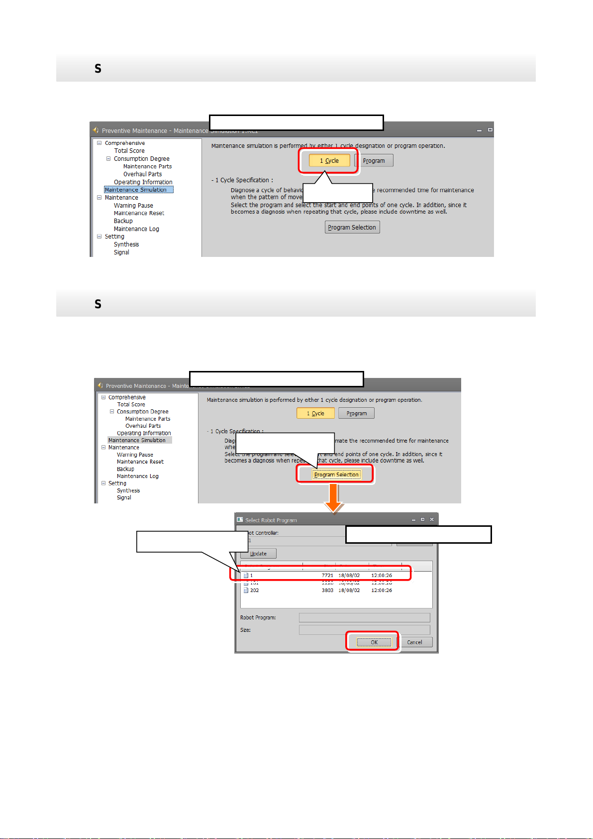
Select "1 Cycle".
3
1) Select "1 Cycle" on the Maintenance Simulation screen.
Maintenance Simulation screen
1 Cycle
Select the execution program.
4
1) Click [Program Selection] on the Maintenance Simulation screen.
Maintenance Simulation screen
Program selection
Select Robot Program screen
Select the program.
2) The "Select Robot Program" screen opens; select the program to run the simulation and click
the "OK" button.
Maintenance simulation 42
Page 53

Select the start line and end line of the program.
5
1) The Select Program Line Number
Include all instructions required for 1 Cycle operation in the line selection range.
(*1) If the start line number is greater than the end line number, an error message is displayed.
(*2) If an error occurred while the maintenance simulation is running, an error message is displayed.
execute again from Step 3.
Select Program Line Number screen
2) Line number input box
3) Starts estimation
Click to input line
numbers.
Caution
Robot program is executed.
6
1) The status of the operating panel indicates "During maintenance simulation", and the robot
Operation Panel
3D Monitor
You can use stop button to
stop the simulation.
Maintenance
simulation is ongoing
ESTPROG
program (*)
screen appears.
2) Select the start line and end line.
<Selection method>
Enter the line number in the input
box at the right side of Start Line
and End Line.
Also, when you click a program
line, that line number is entered in
the input box.
3) Clicking the "Estimated Start"
button starts the maintenance
simulation.
After resetting the error, execute Step 1 to adjust the robot posture to the start posture and then
(Refer to "Note on 1 Cycle operation".)
program is indicated as "ESTPROG(*)", and 1 cycle from the start line and end line specified on
the Select Program Line Number screen is executed. You can check operation of the robot on the
3D monitor.
2) To stop the maintenance simulation halfway through, press the "STOP" button on the operating
panel. The running program stops and the maintenance simulation is stopped.
(*) The program that is automatically generated when 1 Cycle operation is executed. After 1 cycle
operation, you can delete this program if it is unnecessary.
Maintenance simulation 43
Page 54

The simulation results are displayed.
7
The number of years up to the replacement time of grease and the timing belt are displayed. Also,
part having the least years are displayed for each joint axis.
The simulation results are displayed when operation from the start line to end line specified in Step 5
is repeated.
Maintenance Simulation result display
3) Back
2) Operation time of a day
Working days in a month
4) Axes that do not
use target parts
each joint axis name
Number of years up to replacement time
2) Update graph
1) When program operation ends, the maintenance simulation results are displayed.
The displayed results are estimated results based on the value of "Operation Time of a Day" and
"Working Days in a Month".
2) After changing the value of "Operation Time of a Day" and "Working Days in a Month", click the
"Update Graph" button. The simulation results recalculated by the changed conditions are
displayed.
3) Click the "Back" button to return to the initial screen of maintenance simulation.
4) The graph and the number of years are not displayed for joint axes that do not use the target parts.
Number of years up
to replacement for
each joint axis name
Number of years up to the
for each part (number of years of joint
axis having the least number of years)
for overhaul parts, of the reduction gear, bearing, ball screw/ball spline, the number of years of the
recommended overhaul time for
Maintenance simulation 44
Page 55
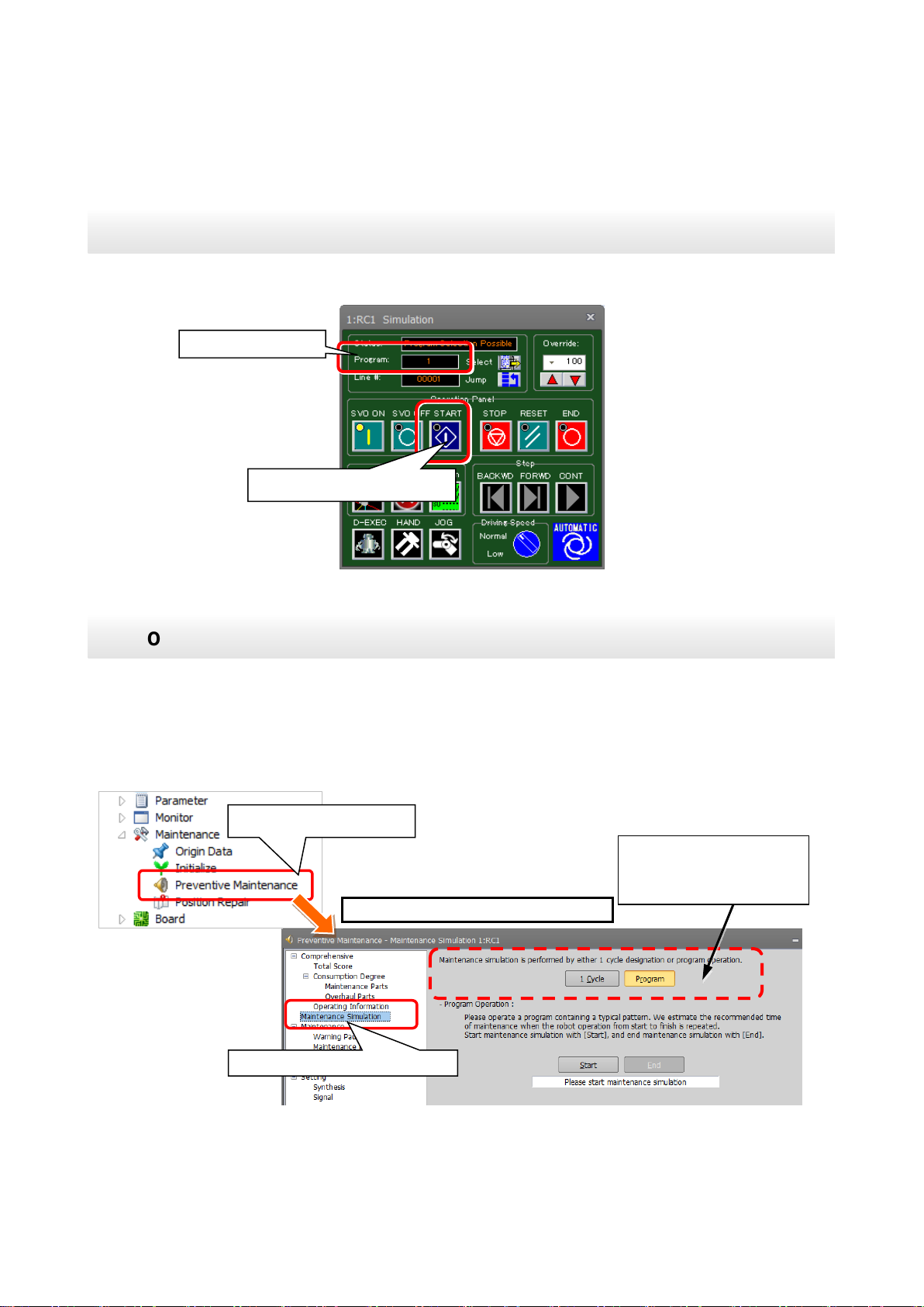
1
1) Automatically run the program that performs maintenance simulation.
Perform automatic operation for the program.
Execution program
Starts automatic operation
Open the Maintenance Simulation screen.
1) While automatically running the program that performs maintenance simulation, from the RT
[Note] When an actual machine is connected, the "1 Cycle" button and "Program" button are not
displayed.
2
Maintenance Simulation screen
Maintenance simulation
Preventive Maintenance
[Note] When an actual
button are not displayed.
8.2 Program operation
Run a program online or in the simulation mode of RT ToolBox3.
While running a robot program automatically, the pats replacement/ the recommended maintenance
time is estimated for operation from when the start button is pressed to when the end button is pressed
is repeated.
ToolBox3 project tree, click [Maintenance] - [Preventive Maintenance] to start.
2) From the preventive maintenance tree, select [Maintenance Simulation].
machine is connected, the "1
Cycle" button and "Program"
Maintenance simulation 45
Page 56

Select the "Program" for the estimation method. (Simulation only)
3
1) When running a program in simulation mode, select "Program" on the Maintenance Simulation
screen.
displayed.
Maintenance Simulation screen
Start maintenance simulation.
1) Clicking the "Start" button on the Maintenance Simulation screen starts maintenance simulation.
button.
4
Maintenance Simulation screen
Start.
Maintenance simulation is ongoing
When an actual machine is
are not displayed.
[Note] When an actual machine is connected, the "1 Cycle" button and "Program" button are not
During simulation, a "During maintenance simulation" message is displayed under the Start
connected, the "1 Cycle"
button and "Program" button
On the operation panel, "Operating" is displayed for Status and the currently running program name
is displayed for Program.
In case of simulation mode, robot motion can be checked on the 3D monitor.
Maintenance simulation 46
Page 57

End the maintenance simulation.
5
1) When a series of operations for performing maintenance simulation have been executed, click
Maintenance Simulation screen
End
the "End" button on the Maintenance Simulation screen.
The maintenance simulation ends and the Maintenance Simulation result screen appears.
(Even though the "End" button is clicked, the robot continues operation.)
Maintenance simulation 47
Page 58

The simulation results are displayed.
6
The maintenance simulation result displayed is when the operation from clicking the "Start" button in
Step 4 to clicking the "End" button in Step 5 is repeated.
"Update Graph" button. The simulation results recalculated by the changed conditions are displayed.
The number of years up to the replacement time of grease and the timing belt are displayed. Also, for
having the least years are displayed for each joint axis.
Maintenance Simulation result display
4) Axes that do not
use target parts
each joint axis name
2) Operation time of a day
Working days in a month
2) Update graph
3) Back
having the least number of years)
1) When program operation ends, the maintenance simulation results are displayed.
The displayed results are estimated results based on the value of "Operation Time of a Day" and
"Working Days in a Month".
2) After changing the value of "Operation Time of a Day" and "Working Days in a Month", click the
3) Click the "Back" button to return to the initial screen of maintenance simulation.
4) The graph and the number of years are not displayed for joint axes that do not use the target parts.
Number of years up
to replacement for
each joint axis
Number of years up to
replacement time for each part
(number of years of joint axis
overhaul parts, of the reduction gear, bearing, ball screw/ball spline, the number of years of the part
Number of years up to the
recommended overhaul time for
Maintenance simulation 48
Page 59

<< MEMO >>
Maintenance simulation 49
Page 60

9. When consumption occurred
Error number
C.712n
Error message
Grease replenishment period
RT ToolBox3
preventive
maintenance
message
The grease (Jn axis) consumption degree exceeded the warning number of days remaining.
Please check the details and prepare for grease supply.
Measures
Replenish grease. After that, reset the consumption degree.
For details of the grease and replenishing procedure, refer to "5. Maintenance and
Inspection" in the separate volume, "Instruction Manual/Robot Arm Setup & Maintenance".
For reset method, refer to "10.2 Maintenance Reset".
Error number
C.712n
Error message
Grease replenishment period
RT ToolBox3
preventive
maintenance
message
The grease (Jn axis) consumption degree exceeded 100%.
Grease supply is recommended.
Measures
Replenish grease. After that, reset the consumption degree.
For details of the grease and replenishing procedure, refer to "5. Maintenance and
Inspection" in the separate volume, "Instruction Manual/Robot Arm Setup & Maintenance".
For reset method, refer to "10.2 Maintenance Reset".
When the consumption status of the target part exceeded the notification day you specified, an error
number and error message corresponding to the status are displayed. Preventive maintenance message is
also displayed in the maintenance message field on the RT ToolBox3 Preventive Maintenance screen.
This section explains the content and measures corresponding to each error number and preventive
maintenance message; take measures corresponding to the error number and preventive maintenance
message given.
For other error numbers, refer to "15Troubleshooting" and the separate "Troubleshooting in CR800 Series
Controller Instruction Manual".
[CAUTION]
For a warning that occurred due to parts consumption, even though the warning signal output is reset, the
RT ToolBox3 preventive maintenance message continues to be displayed if the consumption status is
unchanged.
9.1 Consumption Degree
9.1.1 Maintenance parts
(1) Grease (* n in the table indicates the axis numbers (1 to 6).)
When consumption occurred 50
Page 61

Error number
C.713n
Error message
Timing belt replacement period
RT ToolBox3
preventive
maintenance
message
The timing belt (Jn axis) consumption degree exceeded the warning number of
days remaining. Please check the details and prepare for timing belt replacement.
Measures
Replace the timing belt. After that, reset the consumption degree.
For details of the timing belt and replacement procedure, refer to "5. Maintenance and
Inspection" in the separate volume, "Instruction Manual/Robot Arm Setup & Maintenance".
For reset method, refer to "10.2 Maintenance Reset".
Error number
C.713n
Error message
Timing belt replacement period
RT ToolBox3
preventive
maintenance
message
The timing belt (Jn axis) consumption degree exceeded 100%.
Timing belt replacement is recommended.
Measures
Replace the timing belt. After that, reset the consumption degree.
For details of the timing belt and replacement procedure, refer to "5. Maintenance and
Inspection" in the separate volume, "Instruction Manual/Robot Arm Setup & Maintenance".
For reset method, refer to "10.2 Maintenance Reset".
Error number
C.714n
Error message
Overhaul period (decelerator)
RT ToolBox3
preventive
maintenance
message
The gear (Jn axis) consumption degree exceeded the warning number of days remaining.
Please check the details and prepare for overhaul.
Measures
Perform overhaul of the robot body.
For selection of replacement parts and overhaul implementation timing, consult with our
service affiliated company.
When overhaul is performed, perform reset.
F For reset method, refer to "10.2 Maintenance Reset".
Error number
C.714n
Error message
Overhaul period (decelerator)
RT ToolBox3
preventive
maintenance
message
The gear (Jn axis) consumption degree exceeded 100%.
Overhaul is recommended.
Measures
Perform overhaul of the robot body.
For selection of replacement parts and overhaul implementation timing, consult with our
service affiliated company.
After overhaul, perform reset.
For reset method, refer to "10.2 Maintenance Reset".
(2) Timing belt
9.1.2 Overhaul parts
(1) Reduction gear (* n in the table indicates the axis numbers (1 to 6).
When consumption occurred 51
Page 62

(2) Bearing
Error number
C.715n
Error message
Overhaul period (bearing)
RT ToolBox3
preventive
maintenance
message
The bearing (Jn axis) consumption degree exceeded the warning number of days
remaining. Please check the details and prepare for overhaul.
Measures
Perform overhaul of the robot body.
For selection of replacement parts and overhaul implementation timing, consult with our
service affiliated company.
When overhaul is performed, perform reset.
For reset method, refer to "10.2 Maintenance Reset".
Error number
C.715n
Error message
Overhaul period (bearing)
RT ToolBox3
preventive
maintenance
message
The bearing (Jn axis) consumption degree exceeded 100%.
Overhaul is recommended.
Measures
Perform overhaul of the robot body.
For selection of replacement parts and overhaul implementation timing, consult with our
service affiliated company.
After overhaul, perform reset.
For reset method, refer to "10.2 Maintenance Reset".
Error number
C.716n
Error message
Overhaul period (ball screw)
RT ToolBox3
preventive
maintenance
message
The ball screw (Jn axis) consumption degree exceeded the warning number of days
remaining. Please check the details and prepare for overhaul.
Measures
Perform overhaul of the robot body.
For selection of replacement parts and overhaul implementation timing, consult with our
service affiliated company.
After overhaul, reset the consumption degree.
For reset method, refer to "10.2 Maintenance Reset".
Error number
C.716n
Error message
Overhaul period (ball screw)
RT ToolBox3
preventive
maintenance
message
The ball screw (Jn axis) consumption degree exceeded 100%.
Overhaul is recommended.
Measures
Perform overhaul of the robot body.
For selection of replacement parts and overhaul implementation timing, consult with our
service affiliated company.
After overhaul, reset the consumption degree.
For reset method, refer to "10.2 Maintenance Reset".
(3) Ball screw
When consumption occurred 52
Page 63

Error number
C.7110
Error message
Overhaul period (servo on time)
RT ToolBox3
preventive
maintenance
message
The servo on time exceeded the warning number of days remaining.
Please check the details and prepare for overhaul.
Measures
Perform overhaul of the robot body.
For selection of replacement parts and overhaul implementation timing, consult with our
service affiliated company.
After overhaul, perform reset.
For reset method, refer to "10.2 Maintenance Reset".
Error number
C.7110
Error message
Overhaul period (servo on time)
RT ToolBox3
preventive
maintenance
message
The servo on time exceeded recommended overhaul time.
Overhaul is recommended.
Measures
Perform overhaul of the robot body.
For selection of replacement parts and overhaul implementation timing, consult with our
service affiliated company.
After overhaul, perform reset.
For reset method, refer to "10.2 Maintenance Reset".
When the servo ON time exceeds the specified time (24,000 hours) or the
consumption degree exceeds the warning remaining number of days, we recommend
you perform overhaul of the robot arm.
Caution
9.1.3 Servo ON time
(* n in the table indicates the axis numbers (1 to 6).
When consumption occurred 53
Page 64
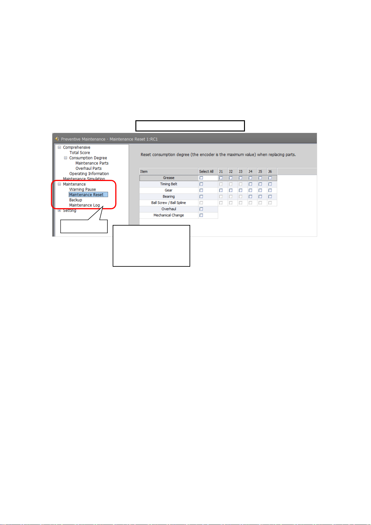
10. Maintenance
1) Start preventive maintenance.
Maintenance
Example: Maintenance Reset screen
On the maintenance screen, you can reset the consumption degree, or can specify backup/restore and
pausing of warning occurrence/warning signal output during maintenance. In addition, you can check the
maintenance log.
2) Click [Maintenance] to expand the menu; the maintenance functions are displayed.
3) Click [Warning Pause], [Maintenance Reset], [Backup], or [Maintenance Log], to switch the
main screen.
(1) Warning Pause
(2) Maintenance Reset
(3) Backup
(4) Maintenance Log
1) Warning Pause : Displays the warning occurred/list of warning signals being output.
Specify pausing of notifications (alarm, dedicated output signal).
2) Maintenance Reset : Resets (clears) the accumulation data related to consumption degree.
3) Backup : Performs backup/restore when migrating the preventive maintenance data to
a different controller.
4) Maintenance Log : Displays the maintenance log recorded during executing maintenance reset.
Maintenance 54
Page 65

(2) Warning
Warning Pause screen
Warning Pause
(5) Writing
(1) Component/Axis Number
(3) Signal Output
Occurrence / Signal Output
(6) Update
Even though you set pause of warning occurrence or signal output, already occurred
warnings and warning signals are not reset.
Use the error reset operation from the teaching pendant or inputting error reset signal
(ERRRESET) to reset those warnings and signals.
Caution
10.1 Warning Pause
Displays the list of warning and warning signals that are occurring or paused.
Usually, the alarm of consumption degree calculation is notified at the intervals you set.
If you desire to stop notification (alarm, dedicated output signal), you can temporarily disable at this stage.
(4) Pause Method of Warning
1) Component/Axis Number:
Indicates the parts and axes currently under warning.
2) Warning:
Indicates either occurring or pause.
Select this check box to pause. Deselect this check box to cancel pause.
3) Signal Output:
Indicates either occurring or pause.
Select this check box to pause. Deselect this check box to cancel pause.
4) Pause Method of Warning Occurrence / Signal Output:
Set the pause method of warning occurrence.
5) Writing:
Writes the content of the selected item.
You can temporarily disable notification related to consumption degree calculation until part
replacement (reset of consumption degree).
6) Update:
Updates the screen display.
Maintenance 55
Page 66
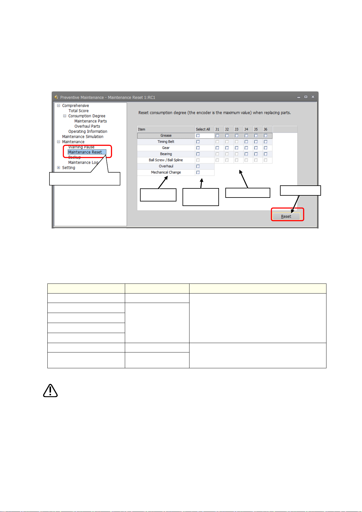
10.2 Maintenance Reset
Item
Implementation timing
Reset target
Grease
At grease replenishing
Accumulated data for consumption degree calculation
of the specified joint axis
Timing belt
At part replacement
Reduction gear
Bearing
Ball screw/ball spline
Overhaul
At overhaul
• Accumulated data of all parts, operating information
(integration time and accumulation count)
Mechanism replacement
At replacement of robot
body
(1) Item
(3) J1 to J6
(4) Reset
(2) Select
All
Maintenance Reset
• Once maintenance reset is executed, the accumulated data before that cannot be
• Perform maintenance reset only when maintenance such as part replacement,
Caution
When part replacement, grease replenishing, or overhaul was performed, the information of the axes for
which maintenance was performed accumulated in the controller needs to be reset.
On the Maintenance Reset screen, you can reset the information held by the controller such as the
consumption degrees calculated by the consumption degree calculation function.
1) Item: Displays parts subject to reset.
2) Select All: Selecting this check box selects all [J1] to [J6] check boxes on the right field.
3) J1 to J6: Depending on the robot type, non-target axes are not selected.
4) Reset: Resets the consumption degree of the items you have selected.
restored.
grease replenishing, overhaul was carried out.
Maintenance 56
Page 67

(2) Restore
Backup
(1) Backup
•
•
occurs when the serial number of the robot is different from the backup data value
• When the serial number of the connected robot was changed, an error (H.7100) is
•
•
performed, the consumption degree calculation result cannot be the correct value.
Caution
10.3 Backup and restore
You can back up or restore preventive maintenance information held in the controller.
To replace the robot body or robot controller only, you need to perform backup/restore of the preventive
maintenance information to migrate the preventive maintenance information.
For backup/restore of the preventive maintenance information, click [Maintenance] - [Backup] of the
preventive maintenance function.
• Replacing the robot controller
When replacing the controller, back up the preventive maintenance information from the previous
controller and restore it in the new controller.
• Exchanging the combination of robot controller and mechanism (between the same models)
When exchanging the combination of controller and mechanism between the same models, before
implementation, back up the preventive maintenance information of the respective controllers and after
implementation restore the information to the replaced controllers.
1) Backup: Save the preventive maintenance information in the robot controller to a file on a
personal computer.
2) Restore: Transfer the information backed up on the personal computer to the robot controller.
The preventive maintenance information of the robot body is saved in the robot
controller; it is necessary to use the correct combination of the robot body and
robot controller.
To replace the robot body or robot controller only, perform backup/restore of
preventive maintenance information to migrate the preventive maintenance
information.
In order to prevent writing backup data to a different robot, an error (H.7101)
when restoring.
output upon power on to notify that effect in order to prevent the occurrence of
unmatched preventive maintenance information when exchanging robot.
When there is no backup data, all consumption degrees can be reset by
performing mechanism replacement of maintenance reset. However, in that case,
the consumption degree calculation result cannot be the correct value. (Refer to
"10.2 Maintenance Reset".)
After replacing the robot controller, if you did not restore the preventive
maintenance information or if you restored it a long time after backup was
Maintenance 57
Page 68

10.3.1 Backup (robot personal computer)
Create a backup file for preventive maintenance information.
1
1) Start preventive maintenance.
Backup
Backup data
Backup
Reading of data completed
Save the preventive maintenance information in the robot controller to a file on a personal computer.
When clicking the [Backup] button, a time stamp folder (folder name: "YYmmdd-HHMMSS") is
automatically created in the [Maintenance] - [PMBackup] folder directly under the project and the
backup data is saved in that folder.
The following describes how to back up preventive maintenance information.
2) Click [Maintenance] - [Backup].
3) When you click Backup on the main screen, backup starts.
4) After a while, a message indicating the end of data read is displayed.
5) A time stamp folder of the current time is created in the [Maintenance] - [PMBackup] folder
directly under the project.
Maintenance 58
Page 69

Restore preventive maintenance information.
1
1) Start preventive maintenance.
Backup
Restore
Select backup folders
Restored maintenance information
10.3.2 Restore (personal computer robot)
Transfer the information backed up on the personal computer to the robot controller.
To restore preventive maintenance information, from the folder selection dialog box, select the folder you
wish to restore.
If there is missing backup data, an error message is displayed and restore is interrupted.
The following describes how to restore preventive maintenance information.
2) Click [Maintenance] - [Backup].
3) When "Restore" is clicked on the main screen, the "Select Backup Folder" appears.
4) Use the "Browse" button to specify the location of the backup folder.
5) The backup folder is displayed on the screen; select the folders you wish to restore and then
press the [OK] button.
6) From the tree on the left side, when you select Total Score, Consumption Degree, or other
preventive maintenance functions, the restored information is displayed on the main screen.
Maintenance 59
Page 70

10.4 Maintenance Log
Maintenance Log
(1) Select Parts
(3) Axis
Number
(4) Date
(5) Consumption
degree
(2) Component
Display the recorded maintenance log.
10.4.1 Maintenance Log screen
The preventive maintenance function stores 10 maintenance log items of the past.
Upon executing maintenance reset, item, date & time, consumption degree [%] and accumulation count
are recorded.
On the Maintenance Log screen, the recorded log is displayed.
Log targets: Grease, timing belt, reduction gear, bearing, ball screw, overhaul
Maintenance 60
1) Select Parts
Select items for which a log is displayed.
(All, Grease, Timing Belt, Gear, Bearing, Ball Screw, Overhaul)
2) Component
Items selected in the Select Parts field are displayed. A maximum of 10 log items are
displayed for each axis.
3) Axis Number
Displays the target axes. Displays "-" for overhaul.
4) Date
Displays the reset date & time.
5) Consumption degree
Displays consumption degree [%] at the time of reset.
Page 71

Log type
Record
target
Log save
count
Type of data log to be recorded
Grease
For each
joint axis
For 10
times
Reset date & time, consumption degree [%] at the time of reset
Timing belt
Reduction gear
Bearing
Ball screw
Ball spline
Overhaul
Robot
Reset date & time, servo ON time [h] at the time of reset
Reset
(implementation)
count
For each
joint axis
−
Grease, timing belt, reduction gear, bearing, ball screw/ball
spline, overhaul
10.4.2 Data to be recorded in the maintenance log
After performing grease replenishing, timing belt replacement, or robot overhaul, upon resetting the
consumption degree of each part, the reset date & time, consumption degree [%] at the time of reset, and
reset count are recorded in the maintenance log.
• The maintenance log of each part and the implementation log of overhaul are recorded.
• When the log save count is exceeded, the old log data is deleted first.
• In case the preventive maintenance function is disabled, a log is also recorded when reset is performed
with the maintenance forecast.
Maintenance 61
Page 72

11. Batch management of maintenance
Communication
protocol
Details
Data acquisition method
MelfaRXM.ocx
This is ActiveX control that communicates with the robot
controller used when you create application software to
communicate with the robot controller.
The instruction manual is included in the following folder
in the CD-ROM of RT ToolBox3 (Standard Version/Pro
Version).
Communication Middleware (MelfaRXM.ocx) Manual:
[Utility¥MelfaRXM¥Doc¥MelfaRxMJ.pdf]
Specify by the dedicated request ID
using the RequestService function.
SLMP
This is a common protocol for inter-application
communication. Reading/writing of robot controller
devices can be performed from a compatible
programmable controller, personal computer or HMI
(Human Machine Interface), and other devices via
Ethernet.
For details, refer to the following instruction manual.
Separate volume, "Instruction Manual Ethernet
Function".
Allocate status variables to D device
(parameters DDEVVL01 to
DDEVVL32)
Robots in the factory
information
Explains how to collectively manage maintenance information of the entire production line with the
host system.
11.1 Functional overview
Maintenance information used in the preventive maintenance function is compatible with the data output in
communication protocol MelfaRXM.ocx, SLMP.
By using this function to collectively manage the maintenance information of the entire production line in a
host system, it is easier to plan maintenance schedules and carry out maintenance activities for the entire
production line.
Use the following means to output preventive maintenance data so the maintenance information of each
robot in your factory can be collectively managed. (For data to be output, refer to "11.2 Output data".)
Batch management of maintenance information 62
Page 73

Output data
Target
Unit
Robot status variable
Parameter
Basic data
Robot body serial number
Character
string
C_RBSerial
RBSERIAL
Power ON time
h (hours)
M_PowOnTime
TIMPOWON
Servo ON time
h (hours)
M_SrvOnTime
TIMSRVON
Operation time
h (hours)
M_PrgTime
TIMPRG
Actual operation time
h (hours)
M_MovTime
TIMMOV
Servo ON count
Times
M_SrvOnNum
NUMSRVON
Motor cumulative rotation
count
Rotation
M_MtRotNum
NUMMTROT
Consumption degree
Mechanism total (maintenance
parts)
%
M_PMCsmMnt
CSMPMMNT
Mechanism total (overhaul
parts)
%
M_PMCsmOH
CSMPMOH
Grease
%
M_PMCsmGrs
CSMPMGRS
Timing belt
%
M_PMCsmBlt
CSMPMBLT
Reduction gear
%
M_PMCsmDec
CSMPMDEC
Bearing
%
M_PMCsmBrg
CSMPMBRG
Ball screw
Ball spline
%
M_PMCsmBss
CSMPMBSS
Remaining time
Mechanism total (maintenance
parts)
h (hours)
M_PMRmnMnt
RMNPMMNT
Servo ON time
(At overhaul implementation)
h (hours)
M_PMRmnSrv
RMNPMSRV
Consumption status
Mechanism total (maintenance
parts)
−
M_PMStsMnt
STSPMMNT
Mechanism total (overhaul
parts)
−
M_PMStsOH
STSPMOH
Grease
−
M_PMStsGrs
STSPMGRS
Timing belt
−
M_PMStsBlt
STSPMBLT
Reduction gear
−
M_PMStsDec
STSPMDEC
Bearing
−
M_PMStsBrg
STSPMBRG
Ball screw
Ball spline
−
M_PMStsBss
STSPMBSS
Servo ON time
(At overhaul implementation)
−
M_PMStsSrv
STSPMSRV
Notification pause
status
Grease
−
M_PMRptGrs
RPTPMGRS
Timing belt
−
M_PMRptBlt
RPTPMBLT
Reduction gear
−
M_PMRptDec
RPTPMDEC
Bearing
−
M_PMRptBrg
RPTPMBRG
Ball screw
Ball spline
−
M_PMRptBss
RPTPMBSS
Servo ON time
(At overhaul implementation)
−
M_PMRptSrv
RPTPMSRV
11.2 Output data
Batch management of maintenance information 63
Page 74

ID value
Function name
212
Get variable value
301
Get parameter value (consider open level)
302
Write parameter value
Output data
Target
Unit
Robot status variable
Parameter
Maintenance Log
Specify data to get
−
−
LOGPMNO
Grease
Piece
M_PMLogGrs
−
Character
string
C_PMLogGrs
LOGPMGRS
Timing belt
Piece
M_PMLogBlt
−
Character
string
C_PMLogBlt
LOGPMBLT
Reduction gear
Piece
M_PMLogDec
−
Character
string
C_PMLogDec
LOGPMDEC
Bearing
Piece
M_PMLogBrg
−
Character
string
C_PMLogBrg
LOGPMBRG
Ball screw
Ball spline
Piece
M_PMLogBss
−
Character
string
C_PMLogBss
LOGPMBSS
Overhaul
Piece
M_PMLogOH
−
Character
string
C_PMLogOH
LOGPMOH
11.3 Request ID (MelfaRXM.ocx) specified by RequestService
You can get robot status variables and parameter values related to the preventive maintenance function
using the existing request ID.
Batch management of maintenance information 64
Page 75

<< MEMO >>
Batch management of maintenance information 65
Page 76

12. Robot (system) status variables
Variable name
Overview
Function
C_RBSerial
Robot body serial number
Returns the serial number of the robot body.
C_RCSerial
Controller serial number
Returns the serial number of the robot controller
Variable name
Overview
Function
M_PowOnTime
Power ON time
Returns the cumulative time of power supply ON of robot
controller from a last overhaul. [hour]
M_SrvOnTime
Servo ON time
Returns the cumulative time of servo ON of the robot body
from a last overhaul. [hour]
M_PrgTime
Operation time
Returns the cumulative time of the operating time of the robot
controller from a last overhaul. [hour]
M_MovTime
Actual operation time
Returns the cumulative time of the moving time of the robot
body from a last overhaul. [hour]
M_SrvOnNum
Servo ON count
Returns the cumulative count of the servo ON of the robot
body from a last overhaul.
M_MtRotNum
Motor cumulative rotation
count
Returns the cumulative number of rotations of the motor of the
robot body from a last overhaul of the specified axis.
Variable name
Overview
Function
M_PMLogGrs
Maintenance count
(grease)
Returns the maintenance count (reset count) of the grease of
the specified axis.
M_PMLogBlt
Maintenance count
(timing belt)
Returns the maintenance count (reset count) of the timing belt
of the specified axis.
M_PMCsmDec
Maintenance count
(reduction gear)
Returns the maintenance count (reset count) of the decelerator
of the specified axis.
M_PMLogBrg
Maintenance count
(bearing)
Returns the maintenance count (reset count) of the bearing of
the specified axis.
M_PMLogBss
Maintenance count
(ball screw/ball spline)
Returns the maintenance count (reset count) of the ball screw /
ball spline of the specified axis.
M_PMLogOH
Maintenance count
(overhaul (servo ON time))
Returns the maintenance count (reset count) of the overhaul.
C_PMLogGrs
Maintenance log (grease)
Returns the maintenance log data (the reset date and time, the
consumption degree when resetting) of the grease.
C_PMLogBlt
Maintenance log (timing
belt)
Returns the maintenance log data (the reset date and time, the
consumption degree when resetting) of the timing belt.
C_PMLogDec
Maintenance log
(reduction gear)
Returns the maintenance log data (the reset date and time, the
consumption degree when resetting) of the decelerator.
C_PMLogBrg
Maintenance log
(bearing)
Returns the maintenance log data (the reset date and time, the
consumption degree when resetting) of the bearing.
C_PMLogBss
Maintenance log
(ball screw/ball spline)
Returns the maintenance log data (the reset date and time, the
consumption degree when resetting) of the ball screw / ball
spline.
C_PMLogOH
Maintenance log
(overhaul (servo ON time))
Returns the maintenance log data (the reset date and time, the
cumulative time of servo ON when resetting) of the overhaul.
12.1 Robot (system) status variable list
Consumption degree calculation function
<Serial number>
<Operating information>
<Maintenance log>
Robot (system) status variables 66
Page 77

Variable name
Overview
Function
M_PMCsmMnt
Consumption degree (mechanism
total (maintenance parts))
Returns the overall consumption degree of the
maintenance part (grease and timing belt). [%]
M_PMCsmOH
Consumption degree
(mechanism total (overhaul parts))
Returns the overall consumption degree of the
overhaul part (decelerator, bearing and ball screw /
ball spline). [%]
M_PMCsmGrs
Consumption degree (grease)
Returns the consumption degree of the grease of the
specified axis. [%]
M_PMLogBlt
Consumption degree (timing belt)
Returns the consumption degree of the timing belt of
the specified axis. [%]
M_PMCsmDec
Consumption degree
(reduction gear)
Returns the consumption degree of the decelerator of
the specified axis. [%]
M_PMCsmBrg
Consumption degree (bearing)
Returns the consumption degree of the bearing of the
specified axis. [%]
M_PMCsmBss
Consumption degree
(ball screw/ball spline)
Returns the consumption degree of the ball screw /
ball spline of the specified axis. [%]
M_PMRmnMnt
Remaining time (mechanism total
(maintenance parts))
Returns the remaining time until maintenance of the
maintenance part (grease and timing belt). [hour]
M_PMRmnSrv
Remaining time (servo ON time)
Returns the remaining time until specified time of an
overhaul of the cumulative time of servo ON. [hour]
Variable name
Overview
Function
M_PMStsMnt
Consumption status (mechanism
total (maintenance parts))
Returns the consumption status of the maintenance
part (grease and timing belt).
M_PMStsOH
Consumption status
(mechanism total (overhaul parts))
Returns the consumption status of the overhaul part
(decelerator, bearing and ball screw / ball spline).
M_PMStsGrs
Consumption status (grease)
Returns the consumption status of grease of the
specified axis.
M_PMStsBlt
Consumption status (timing belt)
Returns the consumption status of timing belt of the
specified axis.
M_PMStsDec
Consumption status
(reduction gear)
Returns the consumption status of decelerator of the
specified axis.
M_PMStsBrg
Consumption status (bearing)
Returns the consumption status of bearing of the
specified axis.
M_PMStsBss
Consumption status
(ball screw/ball spline)
Returns the consumption status of ball screw / ball
spline of the specified axis.
M_PMStsSrv
Consumption status
(servo ON time)
Returns the arrival status to the specified time of an
overhaul of the cumulative time of servo ON.
<Consumption degree>
<Consumption status>
Robot (system) status variables 67
Page 78

<Notification>
Variable name
Overview
Function
M_PMRptGrs
Notification pause status (grease)
Returns the stop status of warning / signal output, of
grease consumption of the specified axis.
M_PMRptBlt
Notification pause status
(timing belt)
Returns the stop status of warning / signal output, of
timing belt consumption of the specified axis.
M_PMRptDec
Notification pause status
(reduction gear)
Returns the stop status of warning / signal output, of
decelerator consumption of the specified axis.
M_PMRptBrg
Notification pause status (bearing)
Returns the stop status of warning / signal output, of
bearing consumption of the specified axis.
M_PMRptBss
Notification pause status
(ball screw/ball spline)
Returns the stop status of warning / signal output, of
ball screw / ball spline consumption of the specified
axis.
M_PMRptSrv
Notification pause status
(servo ON time)
Returns the stop status of warning / signal output, of
arrival status to the specified time of an overhaul of
the cumulative time of servo ON
Variable name
Overview
Function
M_SmartPlus
MELFA Smart Plus function usage
status
Refer to the available status of each function of
MELFA Smart Plus.
C_SmartPlus
MELFA Smart Plus function name
Returns the function name of MELFA Smart Plus.
MELFA Smart Plus
<MELFA Smart Plus card>
Robot (system) status variables 68
Page 79

Example) <String variable> = C_RBSerial(<Mechanism number>)
12.2 Consumption degree calculation function
12.2.1 Serial number
C_RBSerial: Robot body serial number
[Function]
Returns the serial number of the robot body.
[Format]
[Terminology]
<String variable> Specify the string variable to assign.
<Mechanism number> Set the mechanism number. (1 to 3)
When omitted, 1 is used.
[Sample]
1 C1$ = C_RBSerial(1) 'The serial number of the robot body (mechanism 1) is set in C1$.
[Explanation]
(1) Returns the serial number of the robot body registered in the "RBSERIAL" parameter.
(2) This variable is read only.
[Related system status variables]
C_RCSerial
Robot (system) status variables 69
Page 80

Example) <String variable> = C_RCSerial
C_RCSerial: Controller serial number
[Function]
Returns the serial number of the robot controller.
[Format]
[Terminology]
<String variable> Specify the string variable to assign.
[Sample]
1 C1$ = C_RCSerial 'The serial number of the robot controller is set in C1$.
[Explanation]
(1) Returns the serial number of the robot controller.
(2) This variable is read only.
[Related system status variables]
C_RBSerial
Robot (system) status variables 70
Page 81

Example) <Numeric variable> = M_PowOnTime
12.2.2 Operating information
M_PowOnTime: Power ON time
[Function]
Returns the cumulative time of power supply ON of robot controller from a last overhaul. [hour]
[Format]
[Terminology]
<Numeric variable> Specify the numeric variable to assign.
[Sample]
1 M1 = M_PowOnTime 'The cumulative time of power ON of the robot controller is set in M1.
[Explanation]
(1) Returns the cumulative time of power ON of the robot controller.
The cumulative time is the time from when the previous overhaul was carried out.
(2) This variable is read only.
(3) Returns "-1" when the preventive maintenance function is disabled.
Robot (system) status variables 71
Page 82

Example) <Numeric variable> = M_SrvOnTime
M_SrvOnTime: Servo ON time
[Function]
Returns the cumulative time of servo ON of the robot body from a last overhaul. [hour]
[Format]
[Terminology]
<Numeric variable> Specify the numeric variable to assign.
[Sample]
1 M1 = M_SrvOnTime 'The cumulative servo ON time of the robot body (mechanism 1) is set in M1.
[Explanation]
(1) Returns the cumulative time of servo ON of the robot body (mechanism 1).
The cumulative time is the time from when the previous overhaul was carried out.
(2) This variable is read only.
(3) Returns "-1" when the preventive maintenance function is disabled.
Robot (system) status variables 72
Page 83

Example) <Numeric variable> = M_PrgTime
M_PrgTime: Operation time
[Function]
Returns the cumulative time of the operating time of the robot controller from a last overhaul. [hour]
[Format]
[Terminology]
<Numeric variable> Specify the numeric variable to assign.
[Sample]
1 M1 = M_PrgTime 'The operation time of the robot controller is set in M1.
[Explanation]
(1) Returns the operation time of the robot controller.
The operation time is the time from when the previous overhaul was carried out.
(2) This variable is read only.
(3) Returns "-1" when the preventive maintenance function is disabled.
Robot (system) status variables 73
Page 84

Example) <Numeric variable> = M_MovTime
M_MovTime: Actual operation time
[Function]
Returns the cumulative time of the moving time of the robot body from a last overhaul. [hour]
[Format]
[Terminology]
<Numeric variable> Specify the numeric variable to assign.
[Sample]
1 M1 = M_MovTime 'The actual operation time of the robot body (mechanism 1) is set in M1.
[Explanation]
(1) Returns the actual operation time of the robot body (mechanism 1).
The actual operation time is the time from when the previous overhaul was carried out.
(2) This variable is read only.
(3) Returns "-1" when the preventive maintenance function is disabled.
Robot (system) status variables 74
Page 85

Example) <Numeric variable> = M_SrvOnNum
M_SrvOnNum: Servo ON count
[Function]
Returns the cumulative count of the servo ON of the robot body from a last overhaul.
[Format]
[Terminology]
<Numeric variable> Specify the joint type variable to assign.
[Sample]
1 M1 = M_SrvOnNum 'The servo ON count of the robot body (mechanism 1) is set in M1.
[Explanation]
(1) Returns the servo ON count of the robot body (mechanism 1).
The count is the accumulation count from when the previous overhaul was carried out.
(2) This variable is read only.
(3) Returns "-1" when the preventive maintenance function is disabled.
Robot (system) status variables 75
Page 86

Example) <Numeric variable> = M_MtRotNum(<Axis number>)
M_MtRotNum: Motor cumulative rotation count
[Function]
Returns the cumulative number of rotations of the motor of the robot body from a last overhaul of the
specified axis.
[Format]
[Terminology]
<Numeric variable> Specify the joint type variable to assign.
<Axis number> Specify the joint axis to get the cumulative rotation count. (1 to 6)
When omitted, 1 is used.
[Sample]
1 M1 = M_MtRotNum(1) 'The motor cumulative rotation count of the J1 axis is set in M1.
[Explanation]
(1) Returns the motor cumulative rotation count of the robot body (mechanism 1).
The rotation count is the accumulation count from when the previous overhaul was carried out.
(2) This variable is read only.
(3) Returns "-1" when the preventive maintenance function is disabled.
(4) Returns "0" when a nonexistent axis is specified in <Axis number>.
Robot (system) status variables 76
Page 87

Example) <Numeric variable> = M_PMLogGrs(<Axis number>)
12.2.3 Maintenance Log
M_PMLogGrs: Maintenance count (grease)
[Function]
Returns the maintenance count (reset count) of the grease of the specified axis.
[Format]
[Terminology]
<Numeric variable> Specify the numeric variable to assign.
<Axis number> Specify the joint axis for which to get a log. (1 to 6)
When omitted, 1 is used.
[Sample]
1 M1 = M_PMLogGrs(1) 'The maintenance count of the grease for the J1 axis is set in M1.
[Explanation]
(1) Returns the maintenance count (reset count) of the grease for the robot body (mechanism 1).
(2) This variable is read only.
(3) Returns "-1" when the preventive maintenance function is disabled.
(4) Returns "0" when a nonexistent axis is specified in <Axis number>.
[Related system status variables]
C_PMLogGrs
Robot (system) status variables 77
Page 88

Example) <Numeric variable> = M_PMLogBlt(<Axis number>)
M_PMLogBlt: Maintenance count (timing belt)
[Function]
Returns the maintenance count (reset count) of the timing belt of the specified axis.
[Format]
[Terminology]
<Numeric variable> Specify the numeric variable to assign.
<Axis number> Specify the joint axis for which to get a log. (1 to 6)
When omitted, 1 is used.
[Sample]
1 M1 = M_PMLogBlt(1) 'The maintenance count of timing belt for the J1 axis is set in M1.
[Explanation]
(1) Returns the maintenance count (reset count) of timing belt of the robot body (mechanism 1).
(2) This variable is read only.
(3) Returns "-1" when the preventive maintenance function is disabled.
(4) Returns "0" when a nonexistent axis is specified in <Axis number>.
[Related system status variables]
C_PMLogBlt
Robot (system) status variables 78
Page 89

Example) <Numeric variable> = M_PMLogDec(<Axis number>)
M_PMLogDec: Maintenance count (reduction gear)
[Function]
Returns the maintenance count (reset count) of the decelerator of the specified axis.
[Format]
[Terminology]
<Numeric variable> Specify the numeric variable to assign.
<Axis number> Specify the joint axis for which to get a log. (1 to 6)
When omitted, 1 is used.
[Sample]
1 M1 = M_PMLogDec(1) 'The maintenance count of the reduction gear for the J1 axis is set in M1.
[Explanation]
(1) Returns the maintenance count (reset count) of the reduction gear of the robot body (mechanism 1).
(2) This variable is read only.
(3) Returns "-1" when the preventive maintenance function is disabled.
(4) Returns "0" when a nonexistent axis is specified in <Axis number>.
[Related system status variables]
C_PMLogDec
Robot (system) status variables 79
Page 90

Example) <Numeric variable> = M_PMLogBrg(<Axis number>)
M_PMLogBrg: Maintenance count (bearing)
[Function]
Returns the maintenance count (reset count) of the bearing of the specified axis.
[Format]
[Terminology]
<Numeric variable> Specify the numeric variable to assign.
<Axis number> Specify the joint axis for which to get a log. (1 to 6)
When omitted, 1 is used.
[Sample]
1 M1 = M_PMLogBrg(1) 'The maintenance count of the bearing of the J1 axis is set in M1.
[Explanation]
(1) Returns the maintenance count (reset count) of the bearing of the robot body (mechanism 1).
(2) This variable is read only.
(3) Returns "-1" when the preventive maintenance function is disabled.
(4) Returns "0" when a nonexistent axis is specified in <Axis number>.
[Related system status variables]
C_PMLogBrg
Robot (system) status variables 80
Page 91

Example) <Numeric variable> = M_PMLogBss(<Axis number>)
M_PMLogBss: Maintenance count (ball screw/ball spline)
[Function]
Returns the maintenance count (reset count) of the ball screw / ball spline of the specified axis.
[Format]
[Terminology]
<Numeric variable> Specify the numeric variable to assign.
<Axis number> Specify the joint axis for which to get a log. (1 to 6)
When omitted, 1 is used.
[Sample]
1 M1 = M_PMLogBss(3) The maintenance count of the ball screw of the J3 axis is set in 'M1.
[Explanation]
(1) Returns the maintenance count (reset count) of the ball screw/ball spline of the robot body (mechanism
1).
(2) This variable is read only.
(3) Returns "-1" when the preventive maintenance function is disabled.
(4) Returns "0" when a nonexistent axis is specified in <Axis number>.
[Related system status variables]
C_PMLogBss
Robot (system) status variables 81
Page 92

Example) <Numeric variable> = M_PMLogOH
M_PMLogOH: Maintenance count (overhaul (servo ON time))
[Function]
Returns the maintenance count (reset count) of the overhaul.
[Format]
[Terminology]
<Numeric variable> Specify the numeric variable to assign.
[Sample]
1 M1 = M_PMLogOH 'The maintenance count of overhaul is set in M1.
[Explanation]
(1) Returns the maintenance count (reset count) of overhaul for the robot body (mechanism 1).
(2) This variable is read only.
(3) Returns "-1" when the preventive maintenance function is disabled.
[Related system status variables]
C_PMLogOH
Robot (system) status variables 82
Page 93

Example) <String variable> = C_PMLogGrs(<Log number>, <Axis number>)
C_PMLogGrs: Maintenance log (grease)
[Function]
Returns the maintenance log data (the reset date and time, the consumption degree when resetting) of the
grease.
[Format]
[Terminology]
<String variable> Specify the string variable to assign.
<Log number> Specify the log number to get. (1 to 10)
The greater the number, the older the log data.
To get the last reset date & time, specify "1".
<Axis number> Specify the joint axis for which to get a log. (1 to 6)
[Sample]
1 C1$ = C_PMLogGrs(1,1) 'The maintenance log of the grease is set in C1$.
[Explanation]
(1) Returns the maintenance log data (reset date & time, consumption degree at the time of reset) of the
grease for the robot body (mechanism 1).
(2) This variable is read only.
(3) Returns "-1.000" when the preventive maintenance function is disabled.
(4) Returns "<Date>, <Time>, <Consumption degree [%] at the time of reset>" when the preventive
maintenance function is enabled.
<Date> is output in "YYYY/MM/DD" format, and <Time> in "hh:mm:ss" format.
Example : "2018/02/01,12:00:00,80.000"
(5) Returns "----/--/--,--:--:--,0.000" when there is no log data specified by <Log number>.
(6) Returns "----/--/--,--:--:--,0.000" when a nonexistence axis is specified in <Axis number>.
[Related system status variables]
M_PMLogGrs
Robot (system) status variables 83
Page 94

Example) <String variable> = C_PMLogBlt(<Log number>, <Axis number>)
C_PMLogBlt: Maintenance log (timing belt)
[Function]
Returns the maintenance log data (the reset date and time, the consumption degree when resetting) of the
timing belt.
[Format]
[Terminology]
<String variable> Specify the string variable to assign.
<Log number> Specify the log number to get. (1 to 10)
The greater the number, the older the log data.
To get the last reset date & time, specify "1".
<Axis number> Specify the joint axis for which to get a log. (1 to 6)
[Sample]
1 C1$ = C_PMLogBlt(1,1) 'The maintenance log of the timing belt is set in C1$.
[Explanation]
(1) Returns the maintenance log data (reset date & time, consumption degree at the time of reset) of the
timing belt of the robot body (mechanism 1).
(2) This variable is read only.
(3) Returns "-1.000" when the preventive maintenance function is disabled.
(4) Returns "<Date>, <Time>, <Consumption degree [%] at the time of reset>" when the preventive
maintenance function is enabled.
<Date> is output in "YYYY/MM/DD" format, and <Time> in "hh:mm:ss" format.
Example : "2018/02/01,12:00:00,80.000"
(5) Returns "----/--/--,--:--:--,0.000" when there is no log data specified by <Log number>.
(6) Returns "----/--/--,--:--:--,0.000" when a nonexistence axis is specified in <Axis number>.
[Related system status variables]
M_PMLogBlt
Robot (system) status variables 84
Page 95

Example) <String variable> = C_PMLogDec(<Log number>, <Axis number>)
C_PMLogDec: Maintenance log (reduction gear)
[Function]
Returns the maintenance log data (the reset date and time, the consumption degree when resetting) of the
decelerator.
[Format]
[Terminology]
<String variable> Specify the string variable to assign.
<Log number> Specify the log number to get. (1 to 10)
The greater the number, the older the log data.
To get the last reset date & time, specify "1".
<Axis number> Specify the joint axis for which to get a log. (1 to 6)
[Sample]
1 C1$ = C_PMLogDec(1,1) 'The maintenance log of the reduction gear is set in C1$.
[Explanation]
(1) Returns the maintenance log data (reset date & time, consumption degree at the time of reset) of the
reduction gear for the robot body (mechanism 1).
(2) This variable is read only.
(3) Returns "-1.000" when the preventive maintenance function is disabled.
(4) Returns "<Date>, <Time>, <Consumption degree [%] at the time of reset>" when the preventive
maintenance function is enabled.
<Date> is output in "YYYY/MM/DD" format, and <Time> in "hh:mm:ss" format.
Example : "2018/02/01,12:00:00,80.000"
(5) Returns "----/--/--,--:--:--,0.000" when there is no log data specified by <Log number>.
(6) Returns "----/--/--,--:--:--,0.000" when a nonexistence axis is specified in <Axis number>.
[Related system status variables]
M_PMLogDec
Robot (system) status variables 85
Page 96

Example) <String variable> = C_PMLogBrg(<Log number>, <Axis number>)
C_PMLogBrg: Maintenance log (bearing)
[Function]
Returns the maintenance log data (the reset date and time, the consumption degree when resetting) of the
bearing.
[Format]
[Terminology]
<String variable> Specify the string variable to assign.
<Log number> Specify the log number to get. (1 to 10)
The greater the number, the older the log data.
To get the last reset date & time, specify "1".
<Axis number> Specify the joint axis for which to get a log. (1 to 6)
[Sample]
1 C1$ = C_PMLogBrg(1,1) 'The maintenance log of the bearing is set in C1$.
[Explanation]
(1) Returns the maintenance log data (reset date & time, consumption degree at the time of reset) of the
bearing of the robot body (mechanism 1).
(2) This variable is read only.
(3) Returns "-1.000" when the preventive maintenance function is disabled.
(4) Returns "<Date>, <Time>, <Consumption degree [%] at the time of reset>" when the preventive
maintenance function is enabled.
<Date> is output in "YYYY/MM/DD" format, and <Time> in "hh:mm:ss" format.
Example : "2018/02/01,12:00:00,80.000"
(5) Returns "----/--/--,--:--:--,0.000" when there is no log data specified by <Log number>.
(6) Returns "----/--/--,--:--:--,0.000" when a nonexistence axis is specified in <Axis number>.
[Related system status variables]
M_PMLogBrg
Robot (system) status variables 86
Page 97

Example) <String variable> = C_PMLogBss(<Log number>, <Axis number>)
C_PMLogBss: Maintenance log (ball screw/ball spline)
[Function]
Returns the maintenance log data (the reset date and time, the consumption degree when resetting) of the
ball screw / ball spline.
[Format]
[Terminology]
<String variable> Specify the string variable to assign.
<Log number> Specify the log number to get. (1 to 10)
The greater the number, the older the log data.
To get the last reset date & time, specify "1".
<Axis number> Specify the joint axis for which to get a log. (1 to 6)
[Sample]
1 C1$ = C_PMLogBss(1,3) 'The maintenance log of the ball screw of the J3 axis is set in C1$.
[Explanation]
(1) Returns the maintenance log data (reset date & time, consumption degree at the time of reset) of the
ball screw/ball spline of the robot body (mechanism 1).
(2) This variable is read only.
(3) Returns "-1.000" when the preventive maintenance function is disabled.
(4) Returns "<Date>, <Time>, <Consumption degree [%] at the time of reset>" when the preventive
maintenance function is enabled.
<Date> is output in "YYYY/MM/DD" format, and <Time> in "hh:mm:ss" format.
Example : "2018/02/01,12:00:00,80.000"
(5) Returns "----/--/--,--:--:--,0.000" when there is no log data specified by <Log number>.
(6) Returns "----/--/--,--:--:--,0.000" when a nonexistence axis is specified in <Axis number>.
[Related system status variables]
M_PMLogBss
Robot (system) status variables 87
Page 98

Example) <String variable> = C_PMLogOH(<Log number>)
C_PMLogOH: Maintenance log (overhaul (servo ON time))
[Function]
Returns the maintenance log data (the reset date and time, the cumulative time of servo ON when
resetting) of the overhaul.
[Format]
[Terminology]
<String variable> Specify the string variable to assign.
<Log number> Specify the log number to get. (1 to 10)
The greater the number, the older the log data.
To get the last reset date & time, specify "1".
When omitted, 1 is used.
[Sample]
1 C1$ = C_PMLogOH(1) 'The maintenance log of overhaul is set in C1$.
[Explanation]
(1) Returns the maintenance log data (reset date & time, servo ON time at the time of reset) of overhaul
for the robot body (mechanism 1).
(2) This variable is read only.
(3) Returns "-1" when the preventive maintenance function is disabled.
(4) Returns "<Date>, <Time>, <Servo ON time [h] at the time of reset>" when the preventive maintenance
function is enabled.
<Date> is output in "YYYY/MM/DD" format, and <Time> in "hh:mm:ss" format.
Example : "2018/02/01,12:00:00,24000"
(5) Returns "----/--/--,--:--:--,0" when there is no log data specified by <Log number>.
[Related system status variables]
M_PMLogOH
Robot (system) status variables 88
Page 99

Example) <Numeric variable> = M_PMCsmMnt
12.2.4 Consumption degree
M_PMCsmMnt: Consumption degree (mechanism total (maintenance parts))
[Function]
Returns the overall consumption degree of the maintenance part (grease and timing belt). [%]
[Format]
[Terminology]
<Numeric variable> Specify the numeric variable to assign.
[Sample]
1 M1 = M_PMCsmMnt 'The overall consumption degree of the maintenance parts is set in M1.
[Explanation]
(1) Returns the overall consumption degree of the maintenance parts (grease, timing belt) of the robot body
(mechanism 1).
(2) This variable is read only.
(3) Returns "-1" when the preventive maintenance function is disabled.
[Related system status variables]
M_PMCsmGrs / M_PMCsmBlt
Robot (system) status variables 89
Page 100

Example) <Numeric variable> = M_PMCsmOH
M_PMCsmOH: Consumption degree (mechanism total (overhaul parts))
[Function]
Returns the overall consumption degree of the overhaul part (decelerator, bearing and ball screw / ball
spline). [%]
[Format]
[Terminology]
<Numeric variable> Specify the numeric variable to assign.
[Sample]
1 M1 = M_PMCsmOH 'The overall consumption degree of the overhaul parts is set in M1.
[Explanation]
(1) Returns the overall consumption degree of the parts (reduction gear, bearing, ball screw, ball spline)
requiring overhaul of the robot body (mechanism 1).
(2) This variable is read only.
(3) Returns "-1" when the preventive maintenance function is disabled.
[Related system status variables]
M_PMCsmDec / M_PMCsmBrg / M_PMCsmBss
Robot (system) status variables 90
 Loading...